EP1991168B1 - Minimally invasive heart valve replacement - Google Patents
Minimally invasive heart valve replacementDownload PDFInfo
- Publication number
- EP1991168B1 EP1991168B1EP07849008.3AEP07849008AEP1991168B1EP 1991168 B1EP1991168 B1EP 1991168B1EP 07849008 AEP07849008 AEP 07849008AEP 1991168 B1EP1991168 B1EP 1991168B1
- Authority
- EP
- European Patent Office
- Prior art keywords
- valve
- arms
- stent
- heart valve
- leaflets
- Prior art date
- Legal status (The legal status is an assumption and is not a legal conclusion. Google has not performed a legal analysis and makes no representation as to the accuracy of the status listed.)
- Active
Links
- 210000003709heart valveAnatomy0.000titleclaimsdescription58
- 239000000463materialSubstances0.000claimsdescription11
- 239000012781shape memory materialSubstances0.000claimsdescription9
- 230000017531blood circulationEffects0.000claimsdescription6
- 230000036760body temperatureEffects0.000claimsdescription6
- 230000002966stenotic effectEffects0.000claimsdescription6
- 230000008859changeEffects0.000claimsdescription3
- 238000009434installationMethods0.000claimsdescription3
- 238000011144upstream manufacturingMethods0.000claimsdescription3
- 238000010792warmingMethods0.000claimsdescription2
- 238000005452bendingMethods0.000claims1
- 230000000295complement effectEffects0.000claims1
- 210000002216heartAnatomy0.000description49
- 210000001765aortic valveAnatomy0.000description43
- 238000005538encapsulationMethods0.000description37
- 238000000034methodMethods0.000description28
- 238000004873anchoringMethods0.000description26
- 210000005240left ventricleAnatomy0.000description21
- 238000002601radiographyMethods0.000description17
- 238000013175transesophageal echocardiographyMethods0.000description17
- 230000010339dilationEffects0.000description15
- 230000002861ventricularEffects0.000description15
- 239000008280bloodSubstances0.000description12
- 210000004369bloodAnatomy0.000description12
- 238000002513implantationMethods0.000description12
- 210000000709aortaAnatomy0.000description10
- 210000000038chestAnatomy0.000description10
- 230000006870functionEffects0.000description10
- 230000003601intercostal effectEffects0.000description10
- 238000010276constructionMethods0.000description9
- 210000001519tissueAnatomy0.000description9
- 210000004115mitral valveAnatomy0.000description8
- 206010002906aortic stenosisDiseases0.000description6
- 230000033001locomotionEffects0.000description6
- 238000002584aortographyMethods0.000description5
- 230000008901benefitEffects0.000description5
- 210000004204blood vesselAnatomy0.000description5
- 230000008439repair processEffects0.000description5
- 210000005241right ventricleAnatomy0.000description5
- 239000000956alloySubstances0.000description4
- 230000002950deficientEffects0.000description4
- 238000013461designMethods0.000description4
- 230000000694effectsEffects0.000description4
- 210000005246left atriumAnatomy0.000description4
- 210000004072lungAnatomy0.000description4
- 229910001000nickel titaniumInorganic materials0.000description4
- HLXZNVUGXRDIFK-UHFFFAOYSA-Nnickel titaniumChemical compound[Ti].[Ti].[Ti].[Ti].[Ti].[Ti].[Ti].[Ti].[Ti].[Ti].[Ti].[Ni].[Ni].[Ni].[Ni].[Ni].[Ni].[Ni].[Ni].[Ni].[Ni].[Ni].[Ni].[Ni].[Ni]HLXZNVUGXRDIFK-UHFFFAOYSA-N0.000description4
- 230000004044responseEffects0.000description4
- 241000283690Bos taurusSpecies0.000description3
- 208000031481Pathologic ConstrictionDiseases0.000description3
- 229910045601alloyInorganic materials0.000description3
- 210000003698chordae tendineaeAnatomy0.000description3
- 230000008602contractionEffects0.000description3
- 210000003540papillary muscleAnatomy0.000description3
- 210000001147pulmonary arteryAnatomy0.000description3
- 210000003102pulmonary valveAnatomy0.000description3
- 230000000452restraining effectEffects0.000description3
- 230000036262stenosisEffects0.000description3
- 208000037804stenosisDiseases0.000description3
- 238000001356surgical procedureMethods0.000description3
- 238000011282treatmentMethods0.000description3
- 210000000591tricuspid valveAnatomy0.000description3
- 208000005189EmbolismDiseases0.000description2
- 241000283073Equus caballusSpecies0.000description2
- 208000032843HemorrhageDiseases0.000description2
- HTTJABKRGRZYRN-UHFFFAOYSA-NHeparinChemical compoundOC1C(NC(=O)C)C(O)OC(COS(O)(=O)=O)C1OC1C(OS(O)(=O)=O)C(O)C(OC2C(C(OS(O)(=O)=O)C(OC3C(C(O)C(O)C(O3)C(O)=O)OS(O)(=O)=O)C(CO)O2)NS(O)(=O)=O)C(C(O)=O)O1HTTJABKRGRZYRN-UHFFFAOYSA-N0.000description2
- 206010067171RegurgitationDiseases0.000description2
- 238000013459approachMethods0.000description2
- 230000023555blood coagulationEffects0.000description2
- 210000003191femoral veinAnatomy0.000description2
- 230000036541healthEffects0.000description2
- 229960002897heparinDrugs0.000description2
- 229920000669heparinPolymers0.000description2
- 239000007943implantSubstances0.000description2
- 230000009545invasionEffects0.000description2
- 230000007774longtermEffects0.000description2
- 238000005259measurementMethods0.000description2
- 229910052751metalInorganic materials0.000description2
- 239000002184metalSubstances0.000description2
- 230000035515penetrationEffects0.000description2
- 210000003516pericardiumAnatomy0.000description2
- 230000002441reversible effectEffects0.000description2
- 210000005245right atriumAnatomy0.000description2
- 238000009958sewingMethods0.000description2
- 229910001285shape-memory alloyInorganic materials0.000description2
- 230000009885systemic effectEffects0.000description2
- 210000000779thoracic wallAnatomy0.000description2
- 210000005166vasculatureAnatomy0.000description2
- 206010001526Air embolismDiseases0.000description1
- 206010002091AnaesthesiaDiseases0.000description1
- 208000037260Atherosclerotic PlaqueDiseases0.000description1
- 208000035143Bacterial infectionDiseases0.000description1
- 206010008479Chest PainDiseases0.000description1
- 241000283086EquidaeSpecies0.000description1
- 206010017533Fungal infectionDiseases0.000description1
- 241000282412HomoSpecies0.000description1
- 241001272720Medialuna californiensisSpecies0.000description1
- 241001465754MetazoaSpecies0.000description1
- 208000020128Mitral stenosisDiseases0.000description1
- 208000031888MycosesDiseases0.000description1
- 208000002193PainDiseases0.000description1
- 239000004792ProleneSubstances0.000description1
- 241000282887SuidaeSpecies0.000description1
- 208000007536ThrombosisDiseases0.000description1
- 230000004913activationEffects0.000description1
- 230000037005anaesthesiaEffects0.000description1
- 210000003484anatomyAnatomy0.000description1
- 238000002399angioplastyMethods0.000description1
- 239000003146anticoagulant agentSubstances0.000description1
- 229940127219anticoagulant drugDrugs0.000description1
- 230000010100anticoagulationEffects0.000description1
- 210000002376aorta thoracicAnatomy0.000description1
- 239000012237artificial materialSubstances0.000description1
- 230000001746atrial effectEffects0.000description1
- 230000001580bacterial effectEffects0.000description1
- 208000022362bacterial infectious diseaseDiseases0.000description1
- 238000013158balloon valvuloplastyMethods0.000description1
- 230000000740bleeding effectEffects0.000description1
- 230000002308calcificationEffects0.000description1
- 230000000747cardiac effectEffects0.000description1
- 210000001715carotid arteryAnatomy0.000description1
- 238000013270controlled releaseMethods0.000description1
- 230000006866deteriorationEffects0.000description1
- 201000010099diseaseDiseases0.000description1
- 208000037265diseases, disorders, signs and symptomsDiseases0.000description1
- 230000008030eliminationEffects0.000description1
- 238000003379elimination reactionMethods0.000description1
- 210000001105femoral arteryAnatomy0.000description1
- 238000002695general anesthesiaMethods0.000description1
- 210000002837heart atriumAnatomy0.000description1
- 230000004217heart functionEffects0.000description1
- 230000006872improvementEffects0.000description1
- 208000014674injuryDiseases0.000description1
- 238000003780insertionMethods0.000description1
- 230000037431insertionEffects0.000description1
- 210000004731jugular veinAnatomy0.000description1
- 210000005244lower chamberAnatomy0.000description1
- 230000013011matingEffects0.000description1
- 230000007246mechanismEffects0.000description1
- 210000004379membraneAnatomy0.000description1
- 239000012528membraneSubstances0.000description1
- 229910001092metal group alloyInorganic materials0.000description1
- 150000002739metalsChemical class0.000description1
- 208000006887mitral valve stenosisDiseases0.000description1
- 238000012986modificationMethods0.000description1
- 230000004048modificationEffects0.000description1
- 230000003387muscularEffects0.000description1
- 210000004165myocardiumAnatomy0.000description1
- 230000003472neutralizing effectEffects0.000description1
- 238000006213oxygenation reactionMethods0.000description1
- 230000036407painEffects0.000description1
- 231100000435percutaneous penetrationToxicity0.000description1
- 239000004033plasticSubstances0.000description1
- 229920003023plasticPolymers0.000description1
- 238000005498polishingMethods0.000description1
- 238000012545processingMethods0.000description1
- 238000011084recoveryMethods0.000description1
- 230000009467reductionEffects0.000description1
- 230000002040relaxant effectEffects0.000description1
- 238000002271resectionMethods0.000description1
- 230000029058respiratory gaseous exchangeEffects0.000description1
- 208000037803restenosisDiseases0.000description1
- 238000004513sizingMethods0.000description1
- 125000006850spacer groupChemical group0.000description1
- 210000001562sternumAnatomy0.000description1
- 210000001321subclavian veinAnatomy0.000description1
- 206010042772syncopeDiseases0.000description1
- 230000007704transitionEffects0.000description1
- 230000008733traumaEffects0.000description1
- 230000002792vascularEffects0.000description1
- 238000009423ventilationMethods0.000description1
Images


Classifications
- A—HUMAN NECESSITIES
- A61—MEDICAL OR VETERINARY SCIENCE; HYGIENE
- A61F—FILTERS IMPLANTABLE INTO BLOOD VESSELS; PROSTHESES; DEVICES PROVIDING PATENCY TO, OR PREVENTING COLLAPSING OF, TUBULAR STRUCTURES OF THE BODY, e.g. STENTS; ORTHOPAEDIC, NURSING OR CONTRACEPTIVE DEVICES; FOMENTATION; TREATMENT OR PROTECTION OF EYES OR EARS; BANDAGES, DRESSINGS OR ABSORBENT PADS; FIRST-AID KITS
- A61F2/00—Filters implantable into blood vessels; Prostheses, i.e. artificial substitutes or replacements for parts of the body; Appliances for connecting them with the body; Devices providing patency to, or preventing collapsing of, tubular structures of the body, e.g. stents
- A61F2/02—Prostheses implantable into the body
- A61F2/24—Heart valves ; Vascular valves, e.g. venous valves; Heart implants, e.g. passive devices for improving the function of the native valve or the heart muscle; Transmyocardial revascularisation [TMR] devices; Valves implantable in the body
- A61F2/2412—Heart valves ; Vascular valves, e.g. venous valves; Heart implants, e.g. passive devices for improving the function of the native valve or the heart muscle; Transmyocardial revascularisation [TMR] devices; Valves implantable in the body with soft flexible valve members, e.g. tissue valves shaped like natural valves
- A61F2/2418—Scaffolds therefor, e.g. support stents
- A—HUMAN NECESSITIES
- A61—MEDICAL OR VETERINARY SCIENCE; HYGIENE
- A61F—FILTERS IMPLANTABLE INTO BLOOD VESSELS; PROSTHESES; DEVICES PROVIDING PATENCY TO, OR PREVENTING COLLAPSING OF, TUBULAR STRUCTURES OF THE BODY, e.g. STENTS; ORTHOPAEDIC, NURSING OR CONTRACEPTIVE DEVICES; FOMENTATION; TREATMENT OR PROTECTION OF EYES OR EARS; BANDAGES, DRESSINGS OR ABSORBENT PADS; FIRST-AID KITS
- A61F2/00—Filters implantable into blood vessels; Prostheses, i.e. artificial substitutes or replacements for parts of the body; Appliances for connecting them with the body; Devices providing patency to, or preventing collapsing of, tubular structures of the body, e.g. stents
- A61F2/02—Prostheses implantable into the body
- A61F2/24—Heart valves ; Vascular valves, e.g. venous valves; Heart implants, e.g. passive devices for improving the function of the native valve or the heart muscle; Transmyocardial revascularisation [TMR] devices; Valves implantable in the body
- A61F2/2427—Devices for manipulating or deploying heart valves during implantation
- A61F2/2439—Expansion controlled by filaments
- A—HUMAN NECESSITIES
- A61—MEDICAL OR VETERINARY SCIENCE; HYGIENE
- A61F—FILTERS IMPLANTABLE INTO BLOOD VESSELS; PROSTHESES; DEVICES PROVIDING PATENCY TO, OR PREVENTING COLLAPSING OF, TUBULAR STRUCTURES OF THE BODY, e.g. STENTS; ORTHOPAEDIC, NURSING OR CONTRACEPTIVE DEVICES; FOMENTATION; TREATMENT OR PROTECTION OF EYES OR EARS; BANDAGES, DRESSINGS OR ABSORBENT PADS; FIRST-AID KITS
- A61F2/00—Filters implantable into blood vessels; Prostheses, i.e. artificial substitutes or replacements for parts of the body; Appliances for connecting them with the body; Devices providing patency to, or preventing collapsing of, tubular structures of the body, e.g. stents
- A61F2/02—Prostheses implantable into the body
- A61F2/24—Heart valves ; Vascular valves, e.g. venous valves; Heart implants, e.g. passive devices for improving the function of the native valve or the heart muscle; Transmyocardial revascularisation [TMR] devices; Valves implantable in the body
- A61F2/2409—Support rings therefor, e.g. for connecting valves to tissue
- A—HUMAN NECESSITIES
- A61—MEDICAL OR VETERINARY SCIENCE; HYGIENE
- A61F—FILTERS IMPLANTABLE INTO BLOOD VESSELS; PROSTHESES; DEVICES PROVIDING PATENCY TO, OR PREVENTING COLLAPSING OF, TUBULAR STRUCTURES OF THE BODY, e.g. STENTS; ORTHOPAEDIC, NURSING OR CONTRACEPTIVE DEVICES; FOMENTATION; TREATMENT OR PROTECTION OF EYES OR EARS; BANDAGES, DRESSINGS OR ABSORBENT PADS; FIRST-AID KITS
- A61F2220/00—Fixations or connections for prostheses classified in groups A61F2/00 - A61F2/26 or A61F2/82 or A61F9/00 or A61F11/00 or subgroups thereof
- A61F2220/0008—Fixation appliances for connecting prostheses to the body
- A—HUMAN NECESSITIES
- A61—MEDICAL OR VETERINARY SCIENCE; HYGIENE
- A61F—FILTERS IMPLANTABLE INTO BLOOD VESSELS; PROSTHESES; DEVICES PROVIDING PATENCY TO, OR PREVENTING COLLAPSING OF, TUBULAR STRUCTURES OF THE BODY, e.g. STENTS; ORTHOPAEDIC, NURSING OR CONTRACEPTIVE DEVICES; FOMENTATION; TREATMENT OR PROTECTION OF EYES OR EARS; BANDAGES, DRESSINGS OR ABSORBENT PADS; FIRST-AID KITS
- A61F2230/00—Geometry of prostheses classified in groups A61F2/00 - A61F2/26 or A61F2/82 or A61F9/00 or A61F11/00 or subgroups thereof
- A61F2230/0002—Two-dimensional shapes, e.g. cross-sections
- A61F2230/0004—Rounded shapes, e.g. with rounded corners
- A61F2230/0013—Horseshoe-shaped, e.g. crescent-shaped, C-shaped, U-shaped
- A—HUMAN NECESSITIES
- A61—MEDICAL OR VETERINARY SCIENCE; HYGIENE
- A61F—FILTERS IMPLANTABLE INTO BLOOD VESSELS; PROSTHESES; DEVICES PROVIDING PATENCY TO, OR PREVENTING COLLAPSING OF, TUBULAR STRUCTURES OF THE BODY, e.g. STENTS; ORTHOPAEDIC, NURSING OR CONTRACEPTIVE DEVICES; FOMENTATION; TREATMENT OR PROTECTION OF EYES OR EARS; BANDAGES, DRESSINGS OR ABSORBENT PADS; FIRST-AID KITS
- A61F2250/00—Special features of prostheses classified in groups A61F2/00 - A61F2/26 or A61F2/82 or A61F9/00 or A61F11/00 or subgroups thereof
- A61F2250/0058—Additional features; Implant or prostheses properties not otherwise provided for
- A61F2250/0059—Additional features; Implant or prostheses properties not otherwise provided for temporary
- A—HUMAN NECESSITIES
- A61—MEDICAL OR VETERINARY SCIENCE; HYGIENE
- A61F—FILTERS IMPLANTABLE INTO BLOOD VESSELS; PROSTHESES; DEVICES PROVIDING PATENCY TO, OR PREVENTING COLLAPSING OF, TUBULAR STRUCTURES OF THE BODY, e.g. STENTS; ORTHOPAEDIC, NURSING OR CONTRACEPTIVE DEVICES; FOMENTATION; TREATMENT OR PROTECTION OF EYES OR EARS; BANDAGES, DRESSINGS OR ABSORBENT PADS; FIRST-AID KITS
- A61F2250/00—Special features of prostheses classified in groups A61F2/00 - A61F2/26 or A61F2/82 or A61F9/00 or A61F11/00 or subgroups thereof
- A61F2250/0058—Additional features; Implant or prostheses properties not otherwise provided for
- A61F2250/006—Additional features; Implant or prostheses properties not otherwise provided for modular
Definitions
- the present inventionrelates to a prosthetic valve for implantation in the heart in a minimally invasive or percutaneous manner, and more particularly to a prosthetic heart valve suitable for replacement of a defective human heart valve, most particularly an aortic valve.
- valves in the heartserve to direct the flow of blood through the two sides of the heart in a forward direction.
- the mitral valve, located between the left atrium and the left ventricle, and the aortic valve, located between the left ventricle and the aortaconstitute the systemic portion of the heart. These two valves direct oxygenated blood coming from the lungs through the left side of the heart into the aorta for distribution throughout the body.
- the right side of the heartincludes the tricuspid valve, located between the right atrium and the right ventricle, and the pulmonary valve, located between the right ventricle and the pulmonary artery. These two valves direct deoxygenated blood returning from the body through the right side of the heart into the pulmonary artery for distribution to the lungs, where it again becomes re-oxygenated to begin its circuit anew.
- Heart valvesare passive structures having leaflets that simply open and close in response to differential pressures on either side of the particular valve.
- the mitral valvehas two leaflets and the tricuspid valve has three.
- the aortic and pulmonary valvesare sometimes referred to as semilunar valves because of the appearance of their three leaflets; these leaflets are shaped somewhat like a half-moon and are sometimes termed cusps.
- the leaflets and surrounding elements of each valvevary with the function of the heart it supports.
- the atrioventricular valvesotherwise known as mitral (in the left chamber of the heart) and tricuspid (in the right chamber of the heart), are generally a continuum extending from the myocardium or muscular wall of the lower chambers, through the papillary muscles, to which is attached a confluence of tendinous rope-like elements, known as chordae tendinae, that are attached to the edges and undersurface of the differently shaped leaflets which open to allow flow and close to stop flow.
- the leafletsterminate at a ring-like structure usually known as an annulus, which is part of the fibrous skeleton of the heart.
- the ventricular chamberWhen the left ventricular wall relaxes, the ventricular chamber enlarges and draws in blood from the atrium as the leaflets of the mitral valve separate, opening the valve. Oxygenated blood flows in a downward direction through the valve, to fill the expanding ventricular cavity. Once the left ventricular cavity has filled, the left ventricle contracts, causing a rapid rise in the left ventricular cavity pressure. This causes the mitral valve to close and opens the aortic valve, allowing oxygenated blood to be ejected from the left ventricle into the aorta.
- the chordae tendineae of the mitral valveprevent the mitral leaflets from prolapsing back into the left atrium when the left ventricular chamber contracts.
- the three leaflets, chordae tendineae, and papillary muscles of the tricuspid valvefunction in a similar manner, in response to the filling of the right ventricle and its subsequent contraction.
- the cusps of the aortic valverespond passively to pressure differentials between the left ventricle and the aorta.
- the aortic valvecusps open to allow the flow of oxygenated blood from the left ventricle into the aorta.
- the aortic valve cuspsreassociate to prevent blood, which has entered the aorta from leaking (regurgitating) back into the left ventricle.
- the pulmonary valve cuspsrespond passively in the same manner in response to relaxation and contraction of the right ventricle in moving deoxygenated blood into the pulmonary artery and thence to the lungs for re-oxygenation.
- These semilunar valvesdo not require associated chordae tendineae or papillary muscles.
- Stenosisis one problem that heart valves may develop in which a valve does not open properly, another is insufficiency, or regurgitation, where a valve fails to close properly.
- a bacterial or fungal infectionmay require that a heart valve be surgically repaired or replaced.
- Sometimes such a problemcan be treated by surgical repair of a valve; however, often a valve is too diseased to repair and must be replaced. If a heart valve must be replaced, there are currently several options available, and the choice of a particular type of artificial valve depends on factors including the location of the valve, the age and other specifics of the patient, and the particular surgeon's experiences and preferences.
- Heart valves or heart valve prostheseshave been produced for more than four decades. Such valves have been made from a variety of materials of biologic and artificial nature; as a result two distinct categories of the prostheses have evolved: biological and mechanical prosthetic heart valves.
- Mechanical or artificial valvesare typically constructed from nonbiological materials, such as plastics, metals and other artificial materials which, while durable, are prone to blood clotting which increases the risk of an embolism.
- Anticoagulantswhich may be taken to prevent blood clotting can possibly complicate a patient's health due to increased risk of hemorrhage.
- Biological or tissue valvesare constructed from animal tissue, such as bovine, equine or porcine tissue, although some efforts have been made at using tissue from a patient for which the valve will be constructed.
- Tissue valvesare often constructed by sewing leaflets of pig aortic valves to a stent to hold the leaflets in proper position, or by constructing valve leaflets from the pericardial sac of cows, horses or pigs and sewing them to a stent.
- the pericardiumis a membrane that surrounds the heart and isolates it from the rest of the chest wall structures.
- porcine, equine or bovine tissueis chemically treated to alleviate antigenicity and to make them more durable.
- tissue valvesdo not cause blood clots to form as readily as do the mechanical valves; therefore, they do not absolutely require life-long systemic anticoagulation.
- the major disadvantage of tissue valvesis that they lack the long-term durability of mechanical valves.
- Aortic stenosisis a very common disease of the aortic valve in the left ventricle of the heart in people above seventy years old and occurs more and more frequently as the subject gets older.
- the aortic valvular orificebecomes tightly stenosed, blood can no longer be freely ejected from the left ventricle.
- the left ventriclehas to markedly increase its ventricular chamber pressure to discharge blood past the stenosed aortic orifice; such causes a patient to have syncope, chest pain and difficulty in breathing.
- Various surgical techniques that have been used to repair a regurgitant or damaged mitral valveinclude annuloplasty, quadrangular resection (narrowing the valve leaflets), and commissurotomy (cutting the valve commissures to separate the valve leaflets).
- the most common treatment for mitral stenosis and diseased aortic valvehas been the replacement of an affected valve by a prosthetic valve via open-heart surgery by excising the valve leaflets of the natural valve and securing a replacement valve in the valve position, usually by suturing the replacement valve to the natural valve annulus.
- valve stenosisIn instances where a patient is deemed operable only at too high a surgical risk, one alternative in valve stenosis has been to dilate the native valve with a balloon catheter to enlarge the valve orifice; however, such practice has experienced a high restenosis rate.
- heart valvescould be replaced using minimally invasive techniques.
- Proposalshave been made to remove a defective heart valve via an endovascular procedure, that is, a procedure where the invasion into the body is through a blood vessel, such as the femoral artery, and is carried out percutaneously and transluminally using the vascular system to convey appropriate devices to the particular body position to carry out the desired procedure.
- Angioplastyis also an example of such a procedure wherein a catheter carrying a small balloon at its distal end is manipulated through the body's vessels to a point where there is a blockage in a vessel. The balloon is expanded to create an opening in the blockage, and then deflated; the catheter and balloon are then removed.
- endovascular procedureshave substantial benefits both from the standpoint of health and safety as well as cost. Such procedures require minimal invasion of the human body, and there is consequently considerable reduction and in some instances even elimination, of the use of a general anesthesia and much shorter hospital stays.
- U.S. Pat. No. 6,168,614 to Andersen et al.discloses a heart valve prosthesis that can be implanted in the body by use of a catheter.
- the valve prosthesisincludes a support structure or stent with a tissue valve connected to it that is delivered in a collapsed shape through a blood vessel. It is secured in expanded condition at a desired location in a blood vessel, e.g. downstream for the aortic valve.
- the prosthesisis delivered in a sheath to a location near the patient's native aortic valve and then expanded from its collapsed configuration to a deployed configuration.
- a variety of arrangementsare described for deploying prostheses of various shapes and designs so that the prosthesis becomes implanted interiorly of the three native leaflets of the aortic valve, which are compressed radially outwardly.
- Sterman et al.U.S. Pat. No. 6,283,127 , the disclosure of which is incorporated herein by reference, discloses a minimally invasive system for facilitating intervention within the heart or great vessels without the need for a median sternotomy or other form of gross thoracotomy in order to try to substantially reduce trauma, risk of complications, recovery time, and pain for the patient.
- the surgical procedureis not endovascular, but is performed through percutaneous penetrations within intercostal spaces of the patient's rib cage, without cutting, removing, or significantly displacing any of the patient's ribs or sternum.
- U.S. Patent No. 6,869,444discloses the implantation of a prosthesis, which may include only a single leaflet for a mitral valve, through a barrel of an implantation device that is inserted either through the left atrial wall or through the apex of the heart.
- a delivery system for delivering a prosthetic heart valve to a patient's heartconfigured to be releasably folded or crimped inside a lumen of the delivery system through a percutaneous intercostal penetration of a patient's chest, or through an opening at a carotid artery, jugular vein, subclavian vein, femoral vein and other blood vessel.
- US 2005/0137689 A1discloses a two piece apparatus for replacement of a patient's heart valve having an anchor piece and an expandable replacement valve piece.
- the anchor piecehas tips for engaging the patient's native valve leaflets.
- WO 2004/103223 A1discloses an annuloplasty ring for repairing a cardiac valve.
- the support member of the ringcomprises a plurality of ring members having a tip portion including an aperature for receiving a wire.
- US 2005/075728discloses a heart valve replacement system.
- the present inventionprovides a prosthetic valve, which is particularly designed for minimally invasive implantation into the heart through the apex of the heart.
- the apex of the heartis the blunt-rounded, inferior extremity of the heart formed by the termini of the left and right ventricles, and in normal healthy humans, it generally lies behind the fifth intercostal space, left from the mid-sternal line.
- the anatomical structure of the apexpermits the introduction of various surgical devices and tools into the heart without significant disruption of natural mechanical and electrical heart function.
- severe size constraintswhich have been a limitation of endovascular surgical methods of repair/replacement are avoided.
- access through the femoral or other vessels in percutaneous endovascular methodsare limited to the diameter of the vessel (approximately 8 mm)
- access through the apexmay reasonably avail itself of an opening as large as about 25 mm.
- Such access to the heartpermits greater flexibility with respect to the construction and delivery of a prosthetic valve for minimally invasive delivery.
- the present inventionfurther provides an envelope or anchoring device that is part of the collapsible-expandable heart valve; it is formed with distal and proximal sections and is made of a shape-memory material.
- the designis such that, after the envelope has been inserted though the orifice of an aortic or other valve, a distal section of it everts and wraps around the free ends of the aortic leaflets so as to eventually seat against the aortic or downstream surface of the leaflets, while a main body section expands radially outward and a proximal section swings radially outward to seat against the ventricular or upstream surface of the aortic leaflets.
- the implanted envelopethus serves as an anchor for a collapsible-expandable heart valve, which may be separately implanted as a second step and secured thereto via interengaging means provided on the envelope and on a stent portion of the prosthetic heart valve.
- a method for anchoring a replacement valve within the confines of a diseased native valve in a minimally invasive fashion in the human heartis disclosed by percutaneously entering the heart through the apex of the heart via an intercostal penetration of the chest.
- the inventionprovides a percutaneously implantable replacement heart valve, which valve comprises an outermost envelope portion of shape-memory material for sandwiching the native leaflets of a stenotic valve between parts thereof, a collapsible-expandable heart valve stent of generally tubular shape which includes proximal and distal rings and at least three spaced apart posts that extend axially between said rings, and a valvular device comprising a plurality of flexible leaflets disposed interior of said steal, which leaflets open to permit blood flow in a downstream direction and close to prevent blood flow in an upstream direction therethrough.
- an anchoring devicefor securing a peroutaneously implantable replacement heart valve in an existing valve in the human heart, which device comprises a framework of generally tubular shape which is constructed of shape-memory material and which has a portion which averts as a result of temperature change and wraps about the native leaflets of a stenotic or malfunctioning valve when positioned in the orifice of such valve, said framework including a central portion, a distal portion and a proximal portion that are integral with one another, and said distal portion of said framework having a memory such that, upon transition to the temperature of the human body, it everts so as to wrap around the free ends of native leaflets of the valve to contact downstream surfaces of the valve leaflets and secure said framework within the human heart valve.
- a minimally invasive method for percutaneously implanting a replacement heart valve in the orifice of a native valve within the human heartcomprises providing an intercostal opening in the chest of the patient and an adjacent opening in the apex of the human heart, inserting a first catheter through said openings and through a ventricle of the heart to the location of a diseased valve, deploying a generally tubular anchoring device of shape-memory material from the distal end of said catheter at a location generally interior of the native valve, locating said anchoring device so that, when its shape-memory causes a distal portion thereof to evert, said anchoring device wraps itself around and about the free ends of the native valve leaflets, allowing a central portion of the anchoring device to expand to a greater diameter within the orifice of the native valve and sandwich the leaflets between it and the everted portion, removing the first catheter and inserting a second catheter that includes a replacement valvular device that
- FIGS. 1 through 4A first preferred embodiment of an anchoring framework structure 11 for an encapsulation envelope or anchoring device incorporating various features of the invention is shown in FIGS. 1 through 4 .
- the frameworkhas a tubular shape and is designed for anchoring a replacement heart valve at the location of a diseased native valve without excising the native valve.
- the encapsulation envelopehas a tubular deployment form and includes this framework 11 surrounded with a covering layer of biocompatible thin sheet material (not shown).
- a delivery implementwhere it is slidably disposed within a catheter that is caused to enter the body through a cannula implanted intercostally in the chest, through which it is directed through the apex region of the heart and, for example, into the left ventricle, and then through the orifice of the aortic valve.
- the encapsulation envelope framework 11is made of wire-like material, which may be of circular, square, rectangular, oval or other cross section, of a shape-alloy material which has sufficient elasticity such that it can be manually crimped or contracted by applying radially inward directed forces to reduce the diameter of the tubular structure. More specifically, the framework 11 is preferably made of a suitable metal or polymeric material that is biocompatible and has shape-memory properties. However, it is more preferably made of a Nitinol alloy that has an activation temperature (Af) below normal body temperature of about 37°C; thus, the radial force it will exert in tending to return to its "memory" shape can be controlled by varying the temperature difference between the Af and the temperature at which it will be deployed.
- Afactivation temperature
- the individual elements of the overall filamentous constructionwill usually have a square, rectangular, round or oval cross section that results from polishing after the structure has preferably been laser-cut from a single tube having an appropriate diameter proportional to the desired final valve size.
- the frameworkis formed to take its ultimate desired final shape and then treated with heat to set its "memory" so it will always return to this shape.
- the framework 11will have superelastic properties at and below normal body temperature so it will exhibit sufficient flexibility to allow it to be manipulated. Accordingly, as the implanted encapsulation envelope gradually warms to body temperature, the framework 11 slowly assumes its desired folded-over final shape which is shown in FIGS. 3 and 4 .
- the envelope framework 11is formed with a central ring portion 13 of generally undulating shape having a plurality of loops 15 arranged in generally sine wave fashion and extending in opposite directions.
- Such constructionsare relatively common in stents for biological heart valves; see for example U.S. Patent No. 6,168,614 .
- Extending in both directions from selected tips of the loops 15are a plurality of arms 17 and 19, as best seen in FIG.
- the constructionis preferably such that distally extending arms 17 and proximally extending arms 19 are arranged to alternate around the perimeter of the illustrated envelope ring 13, with every third proximally extending loop having an arm 19 projecting therefrom and with every third distally extending loop having a distally extending arm 17 projecting therefrom.
- These circular tabs 21can serve as eyelets through which a control string arrangement may be removably connected to the framework of the envelope to facilitate the installation of the envelope within the orifice of the native valve which it is to replace.
- These three eyelets 23serve as connectors through which similar strings or chords can be routed for controlling the expansion or for subsequently causing contraction of the central ring portion 13 of the superelastic envelope framework.
- the framework 11would be laser-cut from a single tube of Nitinol alloy and polished. It would then be shaped to have the desired final shape shown in FIGS. 3 and 4 , where both sets of arms 17 and 19 extend proximally of the central ring 13.
- the central ring 13is formed to have a convex inward or interior surface that is, in essence, a section of a torus. This arrangement facilitates not only the secure implantation of the envelope in its wrapped-around orientation about the aortic leaflets, but it provides an interengagement surface that is employed to anchor the stent of the valvular device, e.g. bioprosthetic heart valve, that will regulate flow through the orifice.
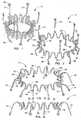
- FIGS. 5 through 6Illustrated in FIGS. 5 through 6 is a preferred embodiment of a tubular stent 29 that is designed to be incorporated as a part of a bioprosthetic heart valve having a shape that will mate with the framework 11 of the implanted envelope just described which will serve to anchor the heart valve in place.
- the tubular stent 29is similarly made of shape-memory material and is constructed to allow it to be expanded and/or contracted to exhibit different diameters.
- the stent 29includes a distal or apical ring 31 and a basal or proximal ring 33, with multiple, in particular three, longitudinally extending posts 35, the ends of which are incorporated into these two, spaced-apart ring portions of the stent.
- the posts 35are located equiangularly at 120° to one another.
- the ring portions and the postsmay be formed of generally wire form material as described hereinbefore with respect to the envelope; however, the stent 29 is again preferably cut from a tube. Both rings are again of undulating design, with the proximal ring 33 preferably having slightly deeper loops. Circular apertures 37 are provided near each end of the three posts; these facilitate the routing of control cords or strings as mentioned hereinbefore with respect to the central ring structure 13 of the envelope.
- the stent 29is likewise more preferably laser-cut from a tube of shape-memory metal alloy.
- flexible sheet material 39e.g. pericardium
- proximal or basal ring structure 33is wrapped around sections of the proximal or basal ring structure 33 to completely surround the ring portions between the posts 35 so that it extends distally interior of the ring within the stent 29 to form the leaflets 41, as shown schematically in FIGS. 9 and 10 .
- the proximal or basal ring 33 of the stentis formed, as can be seen in FIGS. 6 and 9 to have an outwardly concave C-shape contour. It essentially defines a partial toroidal surface as its circumference, and such is matched to the interior surface of the central ring 13 of the envelope framework 11 with which it mates.
- the posts 35have rows of parallel apertures 43 extending throughout their length through which chords or ties 45 are passed, as shown schematically in FIGS. 11 and 12 , to secure lateral edges of the leaflets 41 in place within the interior of the stent 29 to create a working valve.
- Any suitable leaflet designs and attachmentmay be employed, such as those well-known in this art; for example, a preferred pattern of threading such as that shown in FIG. 12 may be used to secure the side edges of three leaflets to one another.
- leaflets of any of the general types shown in the following three Published U.S. Applicationsmay be used: Nos. 2005/0075731 ; 2005/0113910 ; and 2005/0203617 .
- pledgetscan be provided to reinforce the leaflets 41 where there is attachment to the posts.
- a small, lateral thoractomyis performed in the appropriate lateral intercostal space where the apex of the heart is located, and a tubular access cannula or tube with an internal trocar or mandrel is inserted into the retracted incision.
- Purse-string suturesare placed about the apex of the heart and used to secure the cannula in place so that it provides blood-tight access into the heart.
- aortic stenosisis first visualized using contrast (aortography) and radiography or transesophageal echocardiography.
- a dilation balloonis generally first inserted through the access cannula and used to dilate the stenotic valve.
- the diameter achieved through such dilationis measured, using contrast in the dilation balloon and aortography.
- an encapsulation envelope having a framework 11 of the appropriate sizeis selected, and such is loaded into a delivery catheter in tubular form.
- the envelope framework 11 in its tubular deployment form as shown in FIG. 1is positioned about the exterior surface of a tubular delivery implement 47, and the assembly is loaded into the distal end of a catheter (not shown). As depicted schematically in FIG.
- the catheterWith the implement 47 and the crimped, compressed envelope framework 11, which is supported on its outer surface, slidably disposed within the surrounding outer catheter sleeve, the catheter is inserted through the cannula and maneuvered into the left ventricle of the heart, until the distal end of the catheter sleeve reaches the vicinity of the aortic valve 51. Then the delivery implement 47 is extended distally so that it emerges from the end of the catheter sleeve, and it is positioned at a location within the center of the aortic valve.
- the first set of strings 49a that are connected to the ends of the distal arms 17are released in a controlled manner to allow the distal arms 17 of the envelope framework 11 to begin to extend radially outward, as generally illustrated in FIG. 14 , pursuant to their "memory.”
- the proximal ends of the loopsare preferably connected to a ratchet mechanism that facilitates controlled release or rewinding.
- each group of loops of string emanating from a particular longitudinal region of the implement 47is controlled by a separate ratchet; differential passage of string lengths for each of these individual sets 49a, 49b and 49c is thus possible.
- Thisfacilitates the desire to allow little or no expansion of the central ring portion 13 or outward movement of the proximal arms 19 of the framework until the original distal arms have everted.
- these arms 17 of the envelope frameworkwill have assumed an orientation extending proximally at about a 45° angle to the axis of the implement, as shown in FIG. 16 .
- FIG. 19An exemplary umbrella-like valve is illustrated in FIG. 19 as having been advanced to a location near the distal end.
- the valve 55has a plurality of straight ribs 57 that extend radially outward from a center core and that are lightly spring-loaded to a radially extending orientation.
- the ribs 57support a circular panel 59 of flexible film which serves as a temporary valve so long as the implement 47 and the catheter are in position in the heart.
- the valveis pushed from the distal end of the delivery implement 47 by a suitable flexible pusher 56 which slides within the implement 47.
- FIG. 20depicts the umbrella-like temporary valve 55 in its open, slightly compressed orientation during systole as blood flows through the aortic orifice.
- FIG. 21shows the circular valve 55 near its closed position during diastole when it generally blocks blood from the aorta from regurgitating into the left ventricle.
- the valvular deviceWhen the envelope framework 11 has been implanted and a correctly sized valvular device has been chosen, the valvular device is installed on a similar deployment device or delivery implement 61, and it is loaded within a surrounding catheter sleeve. When all is ready, the temporary valve 55 is withdrawn back within the implement 47 that is presently still residing in the aortic valve orifice, and the catheter sleeve and implement are withdrawn. The new catheter carrying the replacement valvular device is now delivered through the cannula and into the left ventricle of the heart.
- the implement 61 carrying the valvular deviceis deployed from the delivery catheter at a location in the aortic region on the aorta side of the encapsulation envelope 11 that was earlier implanted, as depicted in FIG. 22 , where the stent of the valvular device is shown, the interior leaflets being omitted for clarity.
- the stent 29is supported on the delivery implement 61 by two sets of looped strings 63a and 63b similar to those which were earlier described. Then, by observing using radiography or transesophageal echocardiography, precise positioning of the delivery implement 61 is achieved by maneuvering its flexible tip.
- the distal and proximal rings 31, 33 of the stent portionare permitted to expand radially outward by controlled releasing of the sets of strings 63a and 63b.
- the stent 29is constructed so that the curvature of the basal ring 33 very closely matches the convex curvature of the interior surface of the central ring portion 13 of the implanted envelope; if desired, the shape-memory can be employed to accentuate this curvature.
- a self-centering effectis achieved, with the basal ring 33 of the valve stent 29 securely interengaging with the ring 13 of the already implanted encapsulation envelope 11 as the two rings 33 and 13 nest together; simultaneous expansion of both rings 31, 33 of the stent 29 is permitted by releasing the restraining sets of strings 63a and 63b at the same time.
- the two respective curvaturesare preferably selected such that a very slight central annular gap is left through which the string loops 63b that are used to control the expansion-contraction of the basal ring of the heart valve stent can slide.
- the function of the valveis observed by radiography or by transesophageal echocardiography. Should the valve position not be completely satisfactory, the two sets of looped strings 63a, 63b attached to the basal ring 33 and the apical ring 31 of the stent can be pulled to collapse the flexible stent 29 sufficiently to allow the valvular device to be repositioned or even to be completely collapsed and then removed.
- the delivery implement 61is removed; however, the loops 63 of string that extend through the catheter are preferably temporarily left in place. Valve function and effective orifice area are then observed by radiography or the like, and should it be felt that the orifice of the implanted valve is too small, the strings 63 are conveniently used to advantage to guide a dilation balloon into place within the interior region of the basal ring portion 33 of the stent.
- the dilation balloonlocated interior of the basal ring 33 of the stent, it is inflated to dilate this portion of the stent only; this causes both the basal ring and the envelope framework ring 13 with which it is firmly nested to be simultaneously slightly radially expanded, such being made possible as a result of their undulating constructions.
- the balloonis withdrawn once the final diameter of the valve has been determined to be satisfactory, and the sets of strings 63a and 63b are cut at one arm of each loop and pulled out via the other arm.
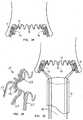
- FIGS. 29-34Disclosed in FIGS. 29-34 is an alternative procedure for implanting an anchoring device having a framework 11 of the construction shown in FIG. 1 within the orifice of a malfunctioning aortic valve; this procedure might be employed instead of the implantation procedure described with respect to FIGS. 13-18 .
- this procedureemploys a catheter 91 and only a single set of strings, i.e. loops 93 that pass through the eyelets 21 that are located at the ends of the proximal arms 19.
- the envelope framework 11is loaded into the proximal end of the catheter 91 with the one set of string loops 93 attached, and it is moved to a location near the distal end of the catheter by a pusher (not shown) similar to that previously mentioned for pushing the temporary valve 55 from the interior of the delivery implement 47.
- FIG. 29shows the crimped, compressed envelope framework 11 disposed within the distal end of the catheter 91, with one set of loops 93 of string attached which pass through the eyelets 21 at the ends of the proximal arms 19 of the framework.
- the catheter 91 with the encapsulation envelope loaded thereinis moved into position within the center of the aortic valve, i.e. to the location as generally depicted in FIG. 30 . Relative movement of a tubular pusher or piston (not shown) and the catheter 91 is then used to effect the emergence of the framework 11 from the distal end of the catheter.
- the catheter sleeve 91is withdrawn proximally a sufficient distance so that the plurality of distal arms 17 are now entirely exterior of the distal end of the catheter, as shown in FIG. 31 .
- the catheter 91can be initially located as shown in FIG. 31 , and the pusher used to cause the emergence of the arms 17 of the framework from its distal end.
- the ring portion 13begins to expand radially outward to entrap the free ends of the leaflets in the bights formed therewith by the everted arms 17, as depicted in FIG. 33 .
- the proximal arms 19are now allowed to follow their shape-memory by relaxing tension on the string loops 93 so that they swing outward where they contact the ventricular surfaces of the aortic leaflets and sandwich the leaflets 53 between the two sets of arms, as earlier described. This orientation is essentially shown in FIG. 33 ; and the location of the envelope framework 11 is then confirmed using radiography or the like.
- each loop 93 of stringis cut at a location outside the body, and the strings are removed by pulling out the other arm of the string loop, leaving the encapsulation envelope of which the framework 11 is a major part, in place, as depicted in FIG. 34 .
- the encapsulation envelopecan still be withdrawn from the aortic valve so long as the loops 93 are attached.
- the elastic proximal arms 19are pulled away from the valve leaflets 53.
- Continued simultaneous gentle advancement of the catheter and pulling on the loopscauses the eyelets 21 and then the arms 19 to be pulled back within the open end of the catheter sleeve and the ring portion 13 to be reduced in diameter.
- the catheter 91 with the distal arms 17 juxtaposed about its outer surfacecan be withdrawn through the cannula and taken out of the body.
- itcan either be reshaped for a second installation try or replaced by another fresh encapsulation envelope.
- FIG. 7A structure 67 of this type is illustrated in FIG. 7 .
- the combined stent/envelope framework 67resembles the heart valve stent 29 in that it includes three similar posts 69 that extend between and form integral parts of a distal or apical ring 71 and a basal or proximal ring 73. It would support three flexible leaflets (not shown) as described hereinbefore.
- Each of the ringsis formed, as before, of a series of sine-wavelike loops.
- the constructionis such that a plurality of distal arms 75 extend from certain of the spaced apart tips of the basal ring 73 that resemble the arms 17, and a plurality of proximal arms 77 extend in the opposite direction from other loops of the basal ring, which arms resemble the arms 19 previously described with regard to the envelope 11.
- Apertured tabs or eyelets 79 at the ends of both sets of arms 75, 79again provide locations for the routing of sets of strings that are used, as explained hereinbefore, to control or reverse the shape-memory movement of the arms.
- a replacement heart valve incorporating the combined stent/envelope structure 67would be loaded onto a delivery implement that includes four sets of longitudinally spaced openings, through which four sets of control strings could be routed to sets of eyelets located at spaced apart locations along the length of the structure 67.
- the heart valve incorporating the combined structure 67could be implanted using a procedure closely patterned after that already described. Because only one step would be required, there would be no need to position a temporary valve within the implantation device for use during the interim period between the two separate steps, as previously described.
- An anesthetized patientis intubated with a single lumen tracheal tubus and arranged so that the patient is lying on his back, slightly twisted in a right lateral position with the left arm elevated to expose the left lateral thorax and to widen the intercostal space.
- the patientis anticoagulated with Heparin 10.000 IU/kg.
- a small lateral thoracotomyhaving a length of about 5 cm, is performed in the 4 th or 5 th lateral intercostal space, where the apex of the heart should be located.
- the intercostal spaceis opened, and the region is retracted to achieve an opening of approximately 5 x 5 cm.
- a double lumen tubus and separate ventilation of the lungsshould not be necessary, because the apex of the heart should be touching the inner thoracic wall so that it will be directly accessible in the intercostal space.
- a purse string 3-0 prolene suture, reinforced with pledgets,is placed around the apex of the heart, and an incision is made at the apex of the heart.
- a tubular access tube or cannula with an internal trocar or mandrelis inserted into the incision at the apex of the heart.
- the purse-string sutureis tied over ear portions of the cannula to secure it in position before the trocar is removed.
- the cannulaprovides blood-tight access into the heart. Blood from remaining bleeding is aspirated, cleaned, and returned to the patient.
- the cannula positioned at the apex of the heartprovides a three dimensional axis about which all devices to be inserted are maneuvered.
- the native aortic valve and all maneuvering of devices, placement of devices, dilation, removing of devices and removing of stringsare preferably continuously visualized and observed by using radiography or transesophageal echocardiography. Contrast to facilitate radiography or transesophageal echocardiography is given through the cannula while carefully avoiding air embolism.
- aortic stenosisis visualized using contrast (aortography) and radiography or transesophageal echocardiography During systole, aortography will show the stenosis of the aortic valve.
- a dilation balloonis inserted through the access tube and used to dilate the stenotic valve.
- the achieved diameteris measured using contrast in the dilation balloon and aortography, and the aortic root and the stenotic aortic valve are measured using transesophageal echocardiography. Based upon these measurements, an appropriate size encapsulation envelope is chosen.
- a catheter containing the crimped encapsulation envelope or anchoring device having the framework 11 on a delivery implement 47is inserted through the cannula. Under control by radiography or transesophageal echocardiography, the tip of the catheter is passed through the aortic valve orifice 51 where it is positioned for delivery of the encapsulation envelope.
- the C-channel central ring section 13 of the encapsulation envelope frameworkis placed distal of the aortic orifice.
- the set of strings 49a holding the distal arms 17 in the delivery orientationare released under control by transesophageal echocardiography or radiography.
- the distal portion of encapsulation envelope framework 11everts, with the arms 17 folding over the aortic surfaces of the aortic valve leaflets 53 somewhat like an umbrella collapses.
- the folding distal arms 17will hook about the free end portions of the aortic leaflets 53, thus encapsulating the calcified and/or cracked aortic valve leaflets by bearing against the aortic surfaces thereof. Subsequently, the set of strings 49b controlling the C-channel ring will be released, allowing it to expand so the outwardly convex C-channel central ring contacts the ventricular surfaces of the aortic valve leaflets.
- All these steps of the deliverycan be undone, by tightening the strings in the reverse order to again crimp the arms 19 and the C-channel ring portion 13 back to reduce its diameter to its initial orientation on the delivery implement and extend the distal arms 17, so as to allow the envelope to be repositioned or even completely removed.
- the hollow delivery implement 47 for the encapsulation envelopealso internally carries a temporary valve 55 in the form of a ribbed circular disc 59, that is unfolded at the tip of the implement; this temporary aortic valve 55 makes the orifice competent during diastole so long as the implement is kept in place.
- the size of the new orifice provided by the encapsulation envelopeis visualized and measured by radiography or transesophageal echocardiography. Should the orifice area be deemed insufficient, the orifice can be dilated via a balloon-valvuloplasty, as by removing the catheter, and inserting a dilation balloon through the cannula. After any such dilation of the encapsulation envelope to a desired new orifice size, the implement 47 with the valve 55 may again be placed in the aortic orifice to function as a temporary valve.
- an expandable prosthetic valvular device of appropriate sizeis chosen.
- the catheteris removed, and a delivery implement 61 having with the crimped valvular device mounted thereupon is loaded in another catheter, inserted through the cannula and placed at the orifice of the encapsulation envelope under the control of radiography or transesophageal echocardiography. Precise positioning of the delivery implement 61 is achieved by carefully maneuvering its flexible tip. Once in the exact position, as shown in FIG. 23 , the sets of strings 63a and 63b restraining the proximal and distal rings 33, 31 of the heart valve stent are released, allowing the stent to expand.
- Position and orientation of the valvular deviceare controlled by radiography or transesophageal echocardiography with the delivery implement 61 still in place. If the position of the valvular device is not completely satisfactory, the stent 29 can be reduced in diameter by tightening the two sets of strings so as to allow the valvular device to be repositioned or even completely removed.
- the delivery implement 61is removed, while leaving the strings 63 in place. Valve function and effective orifice area.are then observed by radiography or transesophageal echocardiography. If the orifice of the implanted valve is deemed to be too small, having the strings 63 in place facilitates another dilation being performed; the valve can be dilated using the dilation balloon method earlier mentioned. Guided by the strings 63b attached to the basal ring portion 33 of the stent 29, the dilation balloon is placed at the basal ring and inflated to expand the nested rings. Once the final diameter of the valve is satisfactory, the string loops are each cut at one arm and pulled out via the other arm.
- a combined stent/envelope device 67 of the type shown in FIGS. 7 and 8instead of using a separate encapsulation envelope and a separate valvular device as described just above, the initial portion of the implantation procedure remains the same as described above.
- a combined valve/envelope prosthesissuch as one having the encapsulation envelope framework/valve stent 67, allows a single unit to be directly implanted after the primary aortal-valvuloplasty has been accomplished and the appropriate size prosthesis has been chosen.
- a delivery implant with a heart valvewhich incorporates the combined framework/stent mounted thereupon, that is restrained by four sets of looped strings, is loaded in a catheter and inserted through the cannula; it is moved to the desired location in the aortic valve orifice, under control using radiography or transesophageal echocardiography. Precise positioning of the delivery implement is achieved by maneuvering its flexible tip. Once in the exact position, a first set of strings restraining the distal arms 75 is released allowing this distal section of the envelope portion to fold over the leaflets; the implement is then withdrawn proximally (as generally depicted in FIG.
- both sets of strings looped through the tabs 79 at the ends of the distal and proximal armsare cut and removed, and the delivery implement is removed, leaving the strings connected to the two ring portions of the stent in place.
- Valve function and effective orifice areais observed by radiography or transesophageal echocardiography.
- the valvecan be dilated using a dilation balloon. Guided by the strings attached to the stent rings, a dilation balloon is placed at the basal ring section 73 and inflated to dilate the stent of the valve and increase the size of the valve orifice.
- the procedureis terminated.
- the delivery deviceis removed, and the apex of the heart is securely closed by tying the purse-string sutures.
- the thoraxis closed, leaving a thorax drain. If deemed necessary or desirable, heparin effects are reversed by giving an adequate neutralizing dose of Protamin.
- Anesthesiais stopped and the patient is weaned from the respirator and extubated in the operation room. The patient is then transferred to an Intermediate Care Unit. After a few hours postoperatively, it should be satisfactory to remove the thorax drain. After about 24 hours, the patient may be discharged.
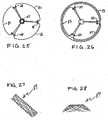
- three separate loops 81each of which would extend radially outward from an aperture in the delivery implement 47 pass through an eyelet 23 in the ring of the envelope framework, and then return through the next adjacent eyelet 23 and back through the aperture in the implement, thus creating what is referred to as a 120° loop, such as the loops 49b in FIGS. 13-18 .
- three loops 83may be used which each pass first through an eyelet 23 in the central ring, for example, and then are routed 360° around the entire ring to return through the same eyelet; such is referred to as a 360° overlap loop arrangement.
- loops of this typemay similarly be used to each control one or more of the distal arms, as well as the proximal arms.
- FIGS. 1-4Although a preferred anchoring envelope framework 11 is illustrated in FIGS. 1-4 , alternative constructions could be employed.
- a wire mesh form of framework 87 for an encapsulation envelopemight be employed; such may be completely formed from a single continuous strand or a plurality of strands of interleaved wire of shape-memory alloy, e.g. Nitinol, or the like. Such could be crimped at a low temperature where it would be superelastic to take a tubular deployment shape, as shown in FIG. 27 ; however, its "memory" shape (illustrated in FIG.
- an anchoring device 111As an alternative to the anchoring device 11 that has distal and proximal arms formed with circular tabs at their ends, an anchoring device 111, as shown in fragmentary perspective in FIG. 35 , might be used.
- This anchoring envelope framework 111includes a central ring 113 similar to that previously described; however, arms are provided by pairs of parallel bars which are joined at their ends by a U-shaped loop. These parallel bars of the distal arms 117 and the proximal arms 119 are respectively interconnected by a plurality of spacers similar to rungs in a ladder.
- Advantages of using this alternative construction for the framework 111include greater surface area contact between the arms 117 and 119 and the respective surfaces of the valve leaflets, and the option of routing the string loops through the arms at a different location than at the very end of the arms, i.e. through the eyelets 21.
Landscapes
- Health & Medical Sciences (AREA)
- Cardiology (AREA)
- Engineering & Computer Science (AREA)
- Biomedical Technology (AREA)
- Heart & Thoracic Surgery (AREA)
- Transplantation (AREA)
- Oral & Maxillofacial Surgery (AREA)
- Vascular Medicine (AREA)
- Life Sciences & Earth Sciences (AREA)
- Animal Behavior & Ethology (AREA)
- General Health & Medical Sciences (AREA)
- Public Health (AREA)
- Veterinary Medicine (AREA)
- Prostheses (AREA)
Description
- This application claims priority from
U.S. Provisional Application No. 60/774,821 filed February 16, 2006 - The present invention relates to a prosthetic valve for implantation in the heart in a minimally invasive or percutaneous manner, and more particularly to a prosthetic heart valve suitable for replacement of a defective human heart valve, most particularly an aortic valve.
- Four valves in the heart serve to direct the flow of blood through the two sides of the heart in a forward direction. The mitral valve, located between the left atrium and the left ventricle, and the aortic valve, located between the left ventricle and the aorta, constitute the systemic portion of the heart. These two valves direct oxygenated blood coming from the lungs through the left side of the heart into the aorta for distribution throughout the body. The right side of the heart includes the tricuspid valve, located between the right atrium and the right ventricle, and the pulmonary valve, located between the right ventricle and the pulmonary artery. These two valves direct deoxygenated blood returning from the body through the right side of the heart into the pulmonary artery for distribution to the lungs, where it again becomes re-oxygenated to begin its circuit anew.
- Heart valves are passive structures having leaflets that simply open and close in response to differential pressures on either side of the particular valve. The mitral valve has two leaflets and the tricuspid valve has three. The aortic and pulmonary valves are sometimes referred to as semilunar valves because of the appearance of their three leaflets; these leaflets are shaped somewhat like a half-moon and are sometimes termed cusps.
- The leaflets and surrounding elements of each valve vary with the function of the heart it supports. The atrioventricular valves, otherwise known as mitral (in the left chamber of the heart) and tricuspid (in the right chamber of the heart), are generally a continuum extending from the myocardium or muscular wall of the lower chambers, through the papillary muscles, to which is attached a confluence of tendinous rope-like elements, known as chordae tendinae, that are attached to the edges and undersurface of the differently shaped leaflets which open to allow flow and close to stop flow. The leaflets terminate at a ring-like structure usually known as an annulus, which is part of the fibrous skeleton of the heart.
- When the left ventricular wall relaxes, the ventricular chamber enlarges and draws in blood from the atrium as the leaflets of the mitral valve separate, opening the valve. Oxygenated blood flows in a downward direction through the valve, to fill the expanding ventricular cavity. Once the left ventricular cavity has filled, the left ventricle contracts, causing a rapid rise in the left ventricular cavity pressure. This causes the mitral valve to close and opens the aortic valve, allowing oxygenated blood to be ejected from the left ventricle into the aorta. The chordae tendineae of the mitral valve prevent the mitral leaflets from prolapsing back into the left atrium when the left ventricular chamber contracts. The three leaflets, chordae tendineae, and papillary muscles of the tricuspid valve function in a similar manner, in response to the filling of the right ventricle and its subsequent contraction.
- The cusps of the aortic valve respond passively to pressure differentials between the left ventricle and the aorta. When the left ventricle contracts, the aortic valve cusps open to allow the flow of oxygenated blood from the left ventricle into the aorta. When the left ventricle relaxes, the aortic valve cusps reassociate to prevent blood, which has entered the aorta from leaking (regurgitating) back into the left ventricle. The pulmonary valve cusps respond passively in the same manner in response to relaxation and contraction of the right ventricle in moving deoxygenated blood into the pulmonary artery and thence to the lungs for re-oxygenation. These semilunar valves do not require associated chordae tendineae or papillary muscles.
- Stenosis is one problem that heart valves may develop in which a valve does not open properly, another is insufficiency, or regurgitation, where a valve fails to close properly. In addition, a bacterial or fungal infection may require that a heart valve be surgically repaired or replaced. Sometimes such a problem can be treated by surgical repair of a valve; however, often a valve is too diseased to repair and must be replaced. If a heart valve must be replaced, there are currently several options available, and the choice of a particular type of artificial valve depends on factors including the location of the valve, the age and other specifics of the patient, and the particular surgeon's experiences and preferences.
- Replacement heart valves or heart valve prostheses have been produced for more than four decades. Such valves have been made from a variety of materials of biologic and artificial nature; as a result two distinct categories of the prostheses have evolved: biological and mechanical prosthetic heart valves. Mechanical or artificial valves are typically constructed from nonbiological materials, such as plastics, metals and other artificial materials which, while durable, are prone to blood clotting which increases the risk of an embolism. Anticoagulants which may be taken to prevent blood clotting can possibly complicate a patient's health due to increased risk of hemorrhage.
- Biological or tissue valves are constructed from animal tissue, such as bovine, equine or porcine tissue, although some efforts have been made at using tissue from a patient for which the valve will be constructed. Tissue valves are often constructed by sewing leaflets of pig aortic valves to a stent to hold the leaflets in proper position, or by constructing valve leaflets from the pericardial sac of cows, horses or pigs and sewing them to a stent. The pericardium is a membrane that surrounds the heart and isolates it from the rest of the chest wall structures. Such porcine, equine or bovine tissue is chemically treated to alleviate antigenicity and to make them more durable. Additional treatments may be applied to avoid structural valve deterioration in the long-term due to calcification. One main advantage of tissue valves is that they do not cause blood clots to form as readily as do the mechanical valves; therefore, they do not absolutely require life-long systemic anticoagulation. The major disadvantage of tissue valves is that they lack the long-term durability of mechanical valves.
- Aortic stenosis is a very common disease of the aortic valve in the left ventricle of the heart in people above seventy years old and occurs more and more frequently as the subject gets older. When the aortic valvular orifice becomes tightly stenosed, blood can no longer be freely ejected from the left ventricle. As a result, the left ventricle has to markedly increase its ventricular chamber pressure to discharge blood past the stenosed aortic orifice; such causes a patient to have syncope, chest pain and difficulty in breathing.
- Various surgical techniques that have been used to repair a regurgitant or damaged mitral valve include annuloplasty, quadrangular resection (narrowing the valve leaflets), and commissurotomy (cutting the valve commissures to separate the valve leaflets). The most common treatment for mitral stenosis and diseased aortic valve has been the replacement of an affected valve by a prosthetic valve via open-heart surgery by excising the valve leaflets of the natural valve and securing a replacement valve in the valve position, usually by suturing the replacement valve to the natural valve annulus. In instances where a patient is deemed operable only at too high a surgical risk, one alternative in valve stenosis has been to dilate the native valve with a balloon catheter to enlarge the valve orifice; however, such practice has experienced a high restenosis rate.
- Generally, it would be desirable if heart valves could be replaced using minimally invasive techniques. Proposals have been made to remove a defective heart valve via an endovascular procedure, that is, a procedure where the invasion into the body is through a blood vessel, such as the femoral artery, and is carried out percutaneously and transluminally using the vascular system to convey appropriate devices to the particular body position to carry out the desired procedure. Angioplasty is also an example of such a procedure wherein a catheter carrying a small balloon at its distal end is manipulated through the body's vessels to a point where there is a blockage in a vessel. The balloon is expanded to create an opening in the blockage, and then deflated; the catheter and balloon are then removed. Such endovascular procedures have substantial benefits both from the standpoint of health and safety as well as cost. Such procedures require minimal invasion of the human body, and there is consequently considerable reduction and in some instances even elimination, of the use of a general anesthesia and much shorter hospital stays.
U.S. Pat. No. 6,168,614 to Andersen et al. , the disclosure of which is incorporated herein by reference, discloses a heart valve prosthesis that can be implanted in the body by use of a catheter. The valve prosthesis includes a support structure or stent with a tissue valve connected to it that is delivered in a collapsed shape through a blood vessel. It is secured in expanded condition at a desired location in a blood vessel, e.g. downstream for the aortic valve.- Until recently, simple implantation of a valve prosthesis for the treatment of aortic stenosis without excising the native valve has been considered generally unrealistic because it was deemed difficult to simply superpose an implanted valve on the distorted stenosed native valve. More recently, however, procedures have been proposed, particularly for replacement of an aortic valve, such as those illustrated in
U.S. Patent Application Publication No. 2005/0143809 to Salahieh et al. , the disclosure of which is incorporated herein by reference, for endovascularly delivering an aortic prosthesis through the patient's aorta and implanting it within the confines of native valve. The prosthesis is delivered in a sheath to a location near the patient's native aortic valve and then expanded from its collapsed configuration to a deployed configuration. A variety of arrangements are described for deploying prostheses of various shapes and designs so that the prosthesis becomes implanted interiorly of the three native leaflets of the aortic valve, which are compressed radially outwardly. - Systems of this general type have shown promise and are considered to be attractive and accordingly, efforts are continuing to produce improvements in such prosthetic valves that can be minimally invasively implanted.
- To repair or replace the mitral valve, a conventional procedure for approaching the left atrium has been employed by the use of intravascular catheterization from a femoral vein through the cardiac septal, which separates the right atrium and the left atrium. In some aspects, this intravascular procedure is not only dangerous and tedious because of long tortuous route, but it has limited use because of the catheter size suitable for intravascular insertion.
- Overall, the use of a minimally invasive approach has a great number of advantages; an endovascular approach has generally been used. However, there is only limited space available within the vasculature; thus, the surgical field is often only as large as the diameter of a blood vessel. Consequently, the introduction of tools and prosthetic devices becomes greatly complicated, and the device to be implanted must be dimensioned and configured to permit it to be introduced into the vasculature, maneuvered therethrough, and then positioned at a desired location. In the majority of aged patients suffering from aortic stenosis, the aortic vessel and aortic arch are affected by calcified atheromatous plaques. Delivery of bulky tools and prosthetic devices retrograde through an atheromatous aortic vessel has increased risk of injuring of the atheromatous aortic wall with subsequent potential embolism and even aortic wall rupture.
Sterman et al., U.S. Pat. No. 6,283,127 , the disclosure of which is incorporated herein by reference, discloses a minimally invasive system for facilitating intervention within the heart or great vessels without the need for a median sternotomy or other form of gross thoracotomy in order to try to substantially reduce trauma, risk of complications, recovery time, and pain for the patient. The surgical procedure is not endovascular, but is performed through percutaneous penetrations within intercostal spaces of the patient's rib cage, without cutting, removing, or significantly displacing any of the patient's ribs or sternum.U.S. Patent No. 6,869,444 , the disclosure of which is also incorporated herein by reference, discloses the implantation of a prosthesis, which may include only a single leaflet for a mitral valve, through a barrel of an implantation device that is inserted either through the left atrial wall or through the apex of the heart.U.S. Patent Application Publication No. 2005/0240200 to Bergheim , the disclosure of which is also incorporated herein by reference, discloses methods and systems for delivering a valve prosthesis to a site within the heart generally at or near the apex of the heart.- Therefore, it would be desirable to provide a delivery system for delivering a prosthetic heart valve to a patient's heart configured to be releasably folded or crimped inside a lumen of the delivery system through a percutaneous intercostal penetration of a patient's chest, or through an opening at a carotid artery, jugular vein, subclavian vein, femoral vein and other blood vessel.
US 2005/0137689 A1 discloses a two piece apparatus for replacement of a patient's heart valve having an anchor piece and an expandable replacement valve piece. The anchor piece has tips for engaging the patient's native valve leaflets.WO 2004/103223 A1 discloses an annuloplasty ring for repairing a cardiac valve. The support member of the ring comprises a plurality of ring members having a tip portion including an aperature for receiving a wire.US 2005/075728 discloses a heart valve replacement system.- It is one aspect of the present invention to provide a prosthetic heart valve with an expandable-collapsible support structure having sufficient flexibility to permit repositioning the valve after its initial placement by reversion to the collapsed stage before final placement as defined in claim 1.
- The present invention provides a prosthetic valve, which is particularly designed for minimally invasive implantation into the heart through the apex of the heart. The apex of the heart is the blunt-rounded, inferior extremity of the heart formed by the termini of the left and right ventricles, and in normal healthy humans, it generally lies behind the fifth intercostal space, left from the mid-sternal line.
- The anatomical structure of the apex permits the introduction of various surgical devices and tools into the heart without significant disruption of natural mechanical and electrical heart function. By using such direct access to the heart through the apex, severe size constraints which have been a limitation of endovascular surgical methods of repair/replacement are avoided. In other words, whereas access through the femoral or other vessels in percutaneous endovascular methods are limited to the diameter of the vessel (approximately 8 mm), access through the apex may reasonably avail itself of an opening as large as about 25 mm. Such access to the heart permits greater flexibility with respect to the construction and delivery of a prosthetic valve for minimally invasive delivery.
- The present invention further provides an envelope or anchoring device that is part of the collapsible-expandable heart valve; it is formed with distal and proximal sections and is made of a shape-memory material. The design is such that, after the envelope has been inserted though the orifice of an aortic or other valve, a distal section of it everts and wraps around the free ends of the aortic leaflets so as to eventually seat against the aortic or downstream surface of the leaflets, while a main body section expands radially outward and a proximal section swings radially outward to seat against the ventricular or upstream surface of the aortic leaflets. This effectively sandwiches the leaflets between the juxtaposed envelope sections, firmly implanting the envelope at the desired location within the orifice of the defective aortic valve. The implanted envelope thus serves as an anchor for a collapsible-expandable heart valve, which may be separately implanted as a second step and secured thereto via interengaging means provided on the envelope and on a stent portion of the prosthetic heart valve.
- In a further aspect not forming part of the invention, a method for anchoring a replacement valve within the confines of a diseased native valve in a minimally invasive fashion in the human heart is disclosed by percutaneously entering the heart through the apex of the heart via an intercostal penetration of the chest.
- In one particular aspect, the invention provides a percutaneously implantable replacement heart valve, which valve comprises an outermost envelope portion of shape-memory material for sandwiching the native leaflets of a stenotic valve between parts thereof, a collapsible-expandable heart valve stent of generally tubular shape which includes proximal and distal rings and at least three spaced apart posts that extend axially between said rings, and a valvular device comprising a plurality of flexible leaflets disposed interior of said steal, which leaflets open to permit blood flow in a downstream direction and close to prevent blood flow in an upstream direction therethrough.
- In another particular aspect, an anchoring device for securing a peroutaneously implantable replacement heart valve in an existing valve in the human heart is disclosed, which device comprises a framework of generally tubular shape which is constructed of shape-memory material and which has a portion which averts as a result of temperature change and wraps about the native leaflets of a stenotic or malfunctioning valve when positioned in the orifice of such valve, said framework including a central portion, a distal portion and a proximal portion that are integral with one another, and said distal portion of said framework having a memory such that, upon transition to the temperature of the human body, it everts so as to wrap around the free ends of native leaflets of the valve to contact downstream surfaces of the valve leaflets and secure said framework within the human heart valve.
- In a further particular aspect not forming part of the invention, a minimally invasive method for percutaneously implanting a replacement heart valve in the orifice of a native valve within the human heart is disclosed, which method comprises providing an intercostal opening in the chest of the patient and an adjacent opening in the apex of the human heart, inserting a first catheter through said openings and through a ventricle of the heart to the location of a diseased valve, deploying a generally tubular anchoring device of shape-memory material from the distal end of said catheter at a location generally interior of the native valve, locating said anchoring device so that, when its shape-memory causes a distal portion thereof to evert, said anchoring device wraps itself around and about the free ends of the native valve leaflets, allowing a central portion of the anchoring device to expand to a greater diameter within the orifice of the native valve and sandwich the leaflets between it and the everted portion, removing the first catheter and inserting a second catheter that includes a replacement valvular device that incorporates an expandable stent loaded on a delivery implement, causing said replacement valvular device to be deployed distally from the open distal end of the catheter, locating the replacement valvular device interior of said implanted anchoring device and allowing the stent to expand in diameter and mate with said anchoring device, and withdrawing the catheter and delivery implement and closing said openings in said heart and the chest of the patient.
FIGURE 1 is a perspective view showing framework embodying various features of the present invention that is included in an anchoring device or encapsulation envelope for a replacement heart valve, which framework is illustrated in its collapsed orientation.FIGURE 2 is a perspective view of the framework ofFIGURE 1 in an intermediate expanded orientation.FIGURE 3 is a perspective view of the framework ofFIGURES 1 and 2 shown in its final "memory" orientation.FIGURE 4 is a front view of the framework shown inFIGURE 3 .FIGURE 5 is a perspective view of a stent for a replacement heart valve shown in its fully retracted or collapsed orientation.FIGURE 6 is a perspective view of the stent ofFIGURE 5 shown in its expanded orientation.FIGURE 7 is a view similar toFIGURE 6 showing a stent for a heart valve which incorporates an anchoring device portion.FIGURE 8 is a cross-sectional view taken generally along the line 8-8 ofFIGURE 7 .FIGURES 9 and 10 are schematic views illustrating how a flexible leaflet may be attached to one ring portion of the heart valve stent ofFIGURE 6 .FIGURES 11 and 12 are fragmentary schematic views showing how individual flexible leaflets may be attached to post portions of the stent and to one another by thread or cords.FIGURE 13 is a schematic view showing the anchoring framework ofFIGURE 1 for an encapsulation envelope loaded onto a delivery implement, with the biologically compatible sheet material that would cover the framework to complete the envelope omitted for clarity.FIGURES 14, 15, 16 ,17 and 18 are schematic views showing successive stages of the implantation of the anchoring framework ofFIGURE 1 of such an encapsulation envelope within the orifice of a malfunctioning aortic valve.FIGURE 19 is an enlarged perspective view of the delivery implement ofFIGURE 13 , following its delivery of the encapsulation envelope, with a portion broken away to show a temporary valve positioned in the lumen thereof near its distal end.FIGURES 20 and21 are schematic views showing the temporary valve ofFIGURE 19 during systole and diastole as it functions in combination with the encapsulation envelope that has been implanted in the aortic valve.FIGURES 22, 23 and 24 are schematic views showing successive stages of (a) delivering a replacement heart valve (with its leaflets omitted for clarity) to the aortic valve of a patient in which the anchoring framework ofFIG. 1 has been implanted and (b) then interengaging the stent of that heart valve with the implanted framework of the encapsulation envelope.FIGURES 25 and 26 are schematic views showing patterns of looped string that may be used to control the expansion or to effect the subsequent collapse of a flexible ring of shape-memory material such as those which form parts of the structures depicted inFIGURES 2 and6 .FIGURES 27 and 28 are perspective views of an alternative embodiment of an anchoring device embodying various features of the invention, shown in its tubular deployment orientation and in its folded memory orientation.FIGURE 29 shows the collapsed framework for an encapsulation envelope as illustrated inFIG. 1 , disposed within a catheter near the distal end thereof with a set of loops of string attached only to the eyelets at the ends of the proximal arms.FIGURE 30 is a schematic perspective view similar toFIG. 29 showing the loaded catheter positioned centrally within a defective aortic valve of a patient.FIGURE 31-33 show a succession of steps where the framework of the encapsulation envelope is caused to emerge from the distal end of the catheter and then change in shape, driven by its shape-memory, so as to encapsulate the tip portions of the aortic valve leaflets as the catheter is withdrawn proximally.FIGURE 34 shows the encapsulation envelope in place, following the cutting of the loops of string and withdrawal of the catheter, ready to accept implantation of a heart valve as depicted inFIGS. 22-24 .FIGURE 35 is a fragmentary perspective view of an alternative embodiment of a framework for an anchoring device similar to that shown inFIG. 1 .- A first preferred embodiment of an anchoring
framework structure 11 for an encapsulation envelope or anchoring device incorporating various features of the invention is shown inFIGS. 1 through 4 . The framework has a tubular shape and is designed for anchoring a replacement heart valve at the location of a diseased native valve without excising the native valve. The encapsulation envelope has a tubular deployment form and includes thisframework 11 surrounded with a covering layer of biocompatible thin sheet material (not shown). It is designed to be deployed in a collapsed condition using a delivery implement where it is slidably disposed within a catheter that is caused to enter the body through a cannula implanted intercostally in the chest, through which it is directed through the apex region of the heart and, for example, into the left ventricle, and then through the orifice of the aortic valve. - The
encapsulation envelope framework 11 is made of wire-like material, which may be of circular, square, rectangular, oval or other cross section, of a shape-alloy material which has sufficient elasticity such that it can be manually crimped or contracted by applying radially inward directed forces to reduce the diameter of the tubular structure. More specifically, theframework 11 is preferably made of a suitable metal or polymeric material that is biocompatible and has shape-memory properties. However, it is more preferably made of a Nitinol alloy that has an activation temperature (Af) below normal body temperature of about 37°C; thus, the radial force it will exert in tending to return to its "memory" shape can be controlled by varying the temperature difference between the Af and the temperature at which it will be deployed. The individual elements of the overall filamentous construction will usually have a square, rectangular, round or oval cross section that results from polishing after the structure has preferably been laser-cut from a single tube having an appropriate diameter proportional to the desired final valve size. After such cutting, the framework is formed to take its ultimate desired final shape and then treated with heat to set its "memory" so it will always return to this shape. By appropriately selecting a Nitinol alloy and processing it, theframework 11 will have superelastic properties at and below normal body temperature so it will exhibit sufficient flexibility to allow it to be manipulated. Accordingly, as the implanted encapsulation envelope gradually warms to body temperature, theframework 11 slowly assumes its desired folded-over final shape which is shown inFIGS. 3 and 4 . - More specifically, the
envelope framework 11 is formed with acentral ring portion 13 of generally undulating shape having a plurality ofloops 15 arranged in generally sine wave fashion and extending in opposite directions. Such constructions are relatively common in stents for biological heart valves; see for exampleU.S. Patent No. 6,168,614 . Extending in both directions from selected tips of theloops 15 are a plurality ofarms FIG. 2 ; although all of theloops 15 could have an arm projecting from the tip thereof, the construction is preferably such that distally extendingarms 17 and proximally extendingarms 19 are arranged to alternate around the perimeter of the illustratedenvelope ring 13, with every third proximally extending loop having anarm 19 projecting therefrom and with every third distally extending loop having adistally extending arm 17 projecting therefrom. - A
small tab 21, which is apertured to form a circle or eyelet, is formed integrally with the end of eacharm circular tabs 21 can serve as eyelets through which a control string arrangement may be removably connected to the framework of the envelope to facilitate the installation of the envelope within the orifice of the native valve which it is to replace. Moreover, there are also multiple, in particular three,circular eyelets 23 incorporated in thecentral ring 13 that are equiangularly spaced from one another (i.e. at 120°); they are each strategically positioned between the legs which form one of the loops which has aproximal arm 19 at its tip, as best seen inFIG. 3 . These threeeyelets 23 serve as connectors through which similar strings or chords can be routed for controlling the expansion or for subsequently causing contraction of thecentral ring portion 13 of the superelastic envelope framework. - Pursuant to the foregoing, the
framework 11 would be laser-cut from a single tube of Nitinol alloy and polished. It would then be shaped to have the desired final shape shown inFIGS. 3 and 4 , where both sets ofarms central ring 13. Thecentral ring 13 is formed to have a convex inward or interior surface that is, in essence, a section of a torus. This arrangement facilitates not only the secure implantation of the envelope in its wrapped-around orientation about the aortic leaflets, but it provides an interengagement surface that is employed to anchor the stent of the valvular device, e.g. bioprosthetic heart valve, that will regulate flow through the orifice. - Illustrated in
FIGS. 5 through 6 is a preferred embodiment of atubular stent 29 that is designed to be incorporated as a part of a bioprosthetic heart valve having a shape that will mate with theframework 11 of the implanted envelope just described which will serve to anchor the heart valve in place. Thetubular stent 29 is similarly made of shape-memory material and is constructed to allow it to be expanded and/or contracted to exhibit different diameters. Basically, thestent 29 includes a distal orapical ring 31 and a basal orproximal ring 33, with multiple, in particular three, longitudinally extendingposts 35, the ends of which are incorporated into these two, spaced-apart ring portions of the stent. Theposts 35 are located equiangularly at 120° to one another. The ring portions and the posts may be formed of generally wire form material as described hereinbefore with respect to the envelope; however, thestent 29 is again preferably cut from a tube. Both rings are again of undulating design, with theproximal ring 33 preferably having slightly deeper loops.Circular apertures 37 are provided near each end of the three posts; these facilitate the routing of control cords or strings as mentioned hereinbefore with respect to thecentral ring structure 13 of the envelope. Thestent 29 is likewise more preferably laser-cut from a tube of shape-memory metal alloy. - To provide leaflets for the valvular device,
flexible sheet material 39, e.g. pericardium, is wrapped around sections of the proximal orbasal ring structure 33 to completely surround the ring portions between theposts 35 so that it extends distally interior of the ring within thestent 29 to form theleaflets 41, as shown schematically inFIGS. 9 and 10 . The proximal orbasal ring 33 of the stent is formed, as can be seen inFIGS. 6 and9 to have an outwardly concave C-shape contour. It essentially defines a partial toroidal surface as its circumference, and such is matched to the interior surface of thecentral ring 13 of theenvelope framework 11 with which it mates. Theposts 35 have rows ofparallel apertures 43 extending throughout their length through which chords or ties 45 are passed, as shown schematically inFIGS. 11 and 12 , to secure lateral edges of theleaflets 41 in place within the interior of thestent 29 to create a working valve. Any suitable leaflet designs and attachment may be employed, such as those well-known in this art; for example, a preferred pattern of threading such as that shown inFIG. 12 may be used to secure the side edges of three leaflets to one another. In general, leaflets of any of the general types shown in the following three PublishedU.S. Applications may be used: Nos. 2005/0075731 ;2005/0113910 ; and2005/0203617 . If desired, pledgets can be provided to reinforce theleaflets 41 where there is attachment to the posts. - To implant the encapsulation envelope, a small, lateral thoractomy is performed in the appropriate lateral intercostal space where the apex of the heart is located, and a tubular access cannula or tube with an internal trocar or mandrel is inserted into the retracted incision. Purse-string sutures are placed about the apex of the heart and used to secure the cannula in place so that it provides blood-tight access into the heart. For replacement of an aortic valve, aortic stenosis is first visualized using contrast (aortography) and radiography or transesophageal echocardiography.
- A dilation balloon is generally first inserted through the access cannula and used to dilate the stenotic valve. The diameter achieved through such dilation is measured, using contrast in the dilation balloon and aortography. Based upon these measurements, an encapsulation envelope having a
framework 11 of the appropriate size is selected, and such is loaded into a delivery catheter in tubular form. Theenvelope framework 11 in its tubular deployment form as shown inFIG. 1 is positioned about the exterior surface of a tubular delivery implement 47, and the assembly is loaded into the distal end of a catheter (not shown). As depicted schematically inFIG. 13 , at three spaced apart locations along the length of the implement 47, threeseparate sets strings 49 are respectively slidably routed through the three sets ofeyelets envelope framework 11. - With the implement 47 and the crimped,
compressed envelope framework 11, which is supported on its outer surface, slidably disposed within the surrounding outer catheter sleeve, the catheter is inserted through the cannula and maneuvered into the left ventricle of the heart, until the distal end of the catheter sleeve reaches the vicinity of theaortic valve 51. Then the delivery implement 47 is extended distally so that it emerges from the end of the catheter sleeve, and it is positioned at a location within the center of the aortic valve. At this point, the first set ofstrings 49a that are connected to the ends of thedistal arms 17 are released in a controlled manner to allow thedistal arms 17 of theenvelope framework 11 to begin to extend radially outward, as generally illustrated inFIG. 14 , pursuant to their "memory." There may be six loops or three loops (with each one passing through two eyelets) ofstring 49a which emerge through the open upper end of the implement; these may be separate loops or all may be part of one continuous length of string. In either instance, the proximal ends of the loops are preferably connected to a ratchet mechanism that facilitates controlled release or rewinding. Once thearms 17 have reached the orientation shown inFIG. 15 where their tips extend radially beyond the tips of theleaflets 53, the implement 47 may be pulled back proximally to some extent. The arrangement at the proximal end of the implement 47 (and the catheter), exterior of the human body, is preferably such that each group of loops of string emanating from a particular longitudinal region of the implement 47 is controlled by a separate ratchet; differential passage of string lengths for each of theseindividual sets central ring portion 13 or outward movement of theproximal arms 19 of the framework until the original distal arms have everted. Upon such eversion, thesearms 17 of the envelope framework will have assumed an orientation extending proximally at about a 45° angle to the axis of the implement, as shown inFIG. 16 . - When this orientation has been reached and the catheter and/or delivery implement 47 are pulled back proximally so that the
ring section 13 is in general alignment with the tips of theleaflets 53, and thearms 17 are now hooked around the free ends of theleaflets 53, as seen inFIG. 16 , the second set ofstrings 49b at the central region, which are attached toeyelets 23 in thering portion 13 of the envelope, are released. Thering portion 13 now expands radially outward to entrap the free ends of theleaflets 53 in the bights formed therewith by the evertedarms 17, with its outwardly concave, C-shaped surface contacting the ventricular surfaces of the leaflets. Finally, the third set ofstrings 49c controlling theproximal arms 19 are released; this allows these arms to follow their shape-memory and swing outward as shown inFIG. 17 so they abut the ventricular surface of the leaflets. Continued movement of both sets of arms sandwiches theleaflets 53 between the two sets of arms, which are located alternately on opposite surfaces of the leaflets, as depicted inFIG. 18 . At this point, all of the expansion steps can still be reversed by simply pulling the loops of strings back through the entry points into the implement 47 in the opposite order; this will again collapse the superelastic framework material of the envelope should it be felt that the location of the encapsulation envelope is not precisely correct. - On the assumption that the exact desired location has been achieved, one arm of each loop of string is cut at a location outside the body, and the strings are removed by pulling out the other arm of each loop of string, leaving the envelope in place (the framework of which has now reached its "memory" orientation shown in
FIGS. 3 and 4 ), as depicted inFIG. 18 . At this point, atemporary valve 55 may be deployed. - Such a valve might be originally loaded internally of the tubular delivery implement 47 in tandem with the envelope which is located on its exterior surface. An exemplary umbrella-like valve is illustrated in
FIG. 19 as having been advanced to a location near the distal end. Thevalve 55 has a plurality ofstraight ribs 57 that extend radially outward from a center core and that are lightly spring-loaded to a radially extending orientation. Theribs 57 support acircular panel 59 of flexible film which serves as a temporary valve so long as the implement 47 and the catheter are in position in the heart. The valve is pushed from the distal end of the delivery implement 47 by a suitable flexible pusher 56 which slides within the implement 47.FIG. 20 depicts the umbrella-liketemporary valve 55 in its open, slightly compressed orientation during systole as blood flows through the aortic orifice.FIG. 21 shows thecircular valve 55 near its closed position during diastole when it generally blocks blood from the aorta from regurgitating into the left ventricle. - When the
envelope framework 11 has been implanted and a correctly sized valvular device has been chosen, the valvular device is installed on a similar deployment device or delivery implement 61, and it is loaded within a surrounding catheter sleeve. When all is ready, thetemporary valve 55 is withdrawn back within the implement 47 that is presently still residing in the aortic valve orifice, and the catheter sleeve and implement are withdrawn. The new catheter carrying the replacement valvular device is now delivered through the cannula and into the left ventricle of the heart. Once in position in the left ventricle, the implement 61 carrying the valvular device is deployed from the delivery catheter at a location in the aortic region on the aorta side of theencapsulation envelope 11 that was earlier implanted, as depicted inFIG. 22 , where the stent of the valvular device is shown, the interior leaflets being omitted for clarity. Thestent 29 is supported on the delivery implement 61 by two sets of loopedstrings 63a and 63b similar to those which were earlier described. Then, by observing using radiography or transesophageal echocardiography, precise positioning of the delivery implement 61 is achieved by maneuvering its flexible tip. Once in the exact desired position so that the C-shaped cross-sectionbasal ring 33 of thevalve stent 29 is aligned with the C-shapedcentral ring 13 of the implantedenvelope 11, the distal andproximal rings strings 63a and 63b. - The
stent 29 is constructed so that the curvature of thebasal ring 33 very closely matches the convex curvature of the interior surface of thecentral ring portion 13 of the implanted envelope; if desired, the shape-memory can be employed to accentuate this curvature. As a result, a self-centering effect is achieved, with thebasal ring 33 of thevalve stent 29 securely interengaging with thering 13 of the already implantedencapsulation envelope 11 as the tworings rings stent 29 is permitted by releasing the restraining sets ofstrings 63a and 63b at the same time. The two respective curvatures are preferably selected such that a very slight central annular gap is left through which the string loops 63b that are used to control the expansion-contraction of the basal ring of the heart valve stent can slide. - When such positioning and the shape-memory expansion has been completed, as shown in
FIG. 23 , the function of the valve is observed by radiography or by transesophageal echocardiography. Should the valve position not be completely satisfactory, the two sets of loopedstrings 63a, 63b attached to thebasal ring 33 and theapical ring 31 of the stent can be pulled to collapse theflexible stent 29 sufficiently to allow the valvular device to be repositioned or even to be completely collapsed and then removed. - Once the final desired placement and mating of the valvular device within the outer encapsulation envelope has been achieved, the delivery implement 61 is removed; however, the loops 63 of string that extend through the catheter are preferably temporarily left in place. Valve function and effective orifice area are then observed by radiography or the like, and should it be felt that the orifice of the implanted valve is too small, the strings 63 are conveniently used to advantage to guide a dilation balloon into place within the interior region of the
basal ring portion 33 of the stent. With the dilation balloon located interior of thebasal ring 33 of the stent, it is inflated to dilate this portion of the stent only; this causes both the basal ring and theenvelope framework ring 13 with which it is firmly nested to be simultaneously slightly radially expanded, such being made possible as a result of their undulating constructions. The balloon is withdrawn once the final diameter of the valve has been determined to be satisfactory, and the sets ofstrings 63a and 63b are cut at one arm of each loop and pulled out via the other arm. - Disclosed in
FIGS. 29-34 is an alternative procedure for implanting an anchoring device having aframework 11 of the construction shown inFIG. 1 within the orifice of a malfunctioning aortic valve; this procedure might be employed instead of the implantation procedure described with respect toFIGS. 13-18 . In comparison to the earlier described procedure, this procedure employs acatheter 91 and only a single set of strings, i.e.loops 93 that pass through theeyelets 21 that are located at the ends of theproximal arms 19. Instead of employing a delivery implement 47 about which theenvelope framework 11 is disposed in surrounding relationship, theenvelope framework 11 is loaded into the proximal end of thecatheter 91 with the one set ofstring loops 93 attached, and it is moved to a location near the distal end of the catheter by a pusher (not shown) similar to that previously mentioned for pushing thetemporary valve 55 from the interior of the delivery implement 47. FIG. 29 shows the crimped,compressed envelope framework 11 disposed within the distal end of thecatheter 91, with one set ofloops 93 of string attached which pass through theeyelets 21 at the ends of theproximal arms 19 of the framework. Thecatheter 91 with the encapsulation envelope loaded therein is moved into position within the center of the aortic valve, i.e. to the location as generally depicted inFIG. 30 . Relative movement of a tubular pusher or piston (not shown) and thecatheter 91 is then used to effect the emergence of theframework 11 from the distal end of the catheter. For example, while the pusher supports theframework 11, thecatheter sleeve 91 is withdrawn proximally a sufficient distance so that the plurality ofdistal arms 17 are now entirely exterior of the distal end of the catheter, as shown inFIG. 31 . Alternatively, thecatheter 91 can be initially located as shown inFIG. 31 , and the pusher used to cause the emergence of thearms 17 of the framework from its distal end.- The
arms 17, which are no longer confined by the surrounding catheter sleeve and which are warming to body temperature, begin to return to their original shape as caused by their shape-memory. This causes thearms 17 to evert initially to a generally horizontal orientation, as shown inFIG. 32 where thetabs 21, at their distal ends, extend past the tips of thenative valve leaflets 53. As thearms 17 continue to evert, thecatheter 91 may be pulled back slightly so that the arms hook around the tips of the leaflets, and relative movement of the catheter and the pusher then causes theentire envelope framework 11 to emerge from the distal end of the catheter, with just enough tension being maintained on the set ofstring loops 93 to position thedistal arms 17 in contact with the aortic surfaces of theleaflets 53. - Once the
entire framework 11 is no longer confined at all by the catheter sleeve, and with thearms 17 now slightly hooked around the free ends of theleaflets 53, thering portion 13 begins to expand radially outward to entrap the free ends of the leaflets in the bights formed therewith by the evertedarms 17, as depicted inFIG. 33 . Theproximal arms 19 are now allowed to follow their shape-memory by relaxing tension on thestring loops 93 so that they swing outward where they contact the ventricular surfaces of the aortic leaflets and sandwich theleaflets 53 between the two sets of arms, as earlier described. This orientation is essentially shown inFIG. 33 ; and the location of theenvelope framework 11 is then confirmed using radiography or the like. If the exact desired location has been achieved, one arm of eachloop 93 of string is cut at a location outside the body, and the strings are removed by pulling out the other arm of the string loop, leaving the encapsulation envelope of which theframework 11 is a major part, in place, as depicted inFIG. 34 . - If before cutting the loops of
string 93 it should be found that the desired location within the aortic valve had not been obtained, although it is not possible to realign or reposition theframework 11, the encapsulation envelope can still be withdrawn from the aortic valve so long as theloops 93 are attached. By distally advancing thecatheter 91 while simultaneously pulling on the set ofstrings 93, the elasticproximal arms 19 are pulled away from thevalve leaflets 53. Continued simultaneous gentle advancement of the catheter and pulling on the loops causes theeyelets 21 and then thearms 19 to be pulled back within the open end of the catheter sleeve and thering portion 13 to be reduced in diameter. Once the major portions of all theproximal arms 19 are within the catheter sleeve, pushing the tubular pusher and the catheter distally through the valve region into the aorta causes thevalve leaflets 53 to slip out of the bight between the everteddistal arms 17 and thering 13 of the anchoring envelope. Once this occurs, further response to the shape-memory of thedistal arms 17 is such that they continue to evert further and wrap tightly onto the outer surface of thecatheter sleeve 91 because theframework 11 is preferably originally set to orient thearms 17 to such a more radially inward attitude. Because the final outer diameter of such aframework 11 is essentially that of thecentral ring portion 13, which now extends only slightly beyond the catheter sleeve, thecatheter 91 with thedistal arms 17 juxtaposed about its outer surface, can be withdrawn through the cannula and taken out of the body. Here it can either be reshaped for a second installation try or replaced by another fresh encapsulation envelope. - As an alternative to using a separate envelope that is initially implanted and then used to subsequently anchor a valvular device in position within an aortic valve or the like, a combination of a heart valve stent and a framework of arms that will wrap around leaves of a malfunctioning valve can be constructed. A
structure 67 of this type is illustrated inFIG. 7 . The combined stent/envelope framework 67 resembles theheart valve stent 29 in that it includes threesimilar posts 69 that extend between and form integral parts of a distal orapical ring 71 and a basal orproximal ring 73. It would support three flexible leaflets (not shown) as described hereinbefore. Each of the rings is formed, as before, of a series of sine-wavelike loops. However, the construction is such that a plurality ofdistal arms 75 extend from certain of the spaced apart tips of thebasal ring 73 that resemble thearms 17, and a plurality ofproximal arms 77 extend in the opposite direction from other loops of the basal ring, which arms resemble thearms 19 previously described with regard to theenvelope 11. Apertured tabs or eyelets 79 at the ends of both sets ofarms envelope structure 67 would be loaded onto a delivery implement that includes four sets of longitudinally spaced openings, through which four sets of control strings could be routed to sets of eyelets located at spaced apart locations along the length of thestructure 67. After the orifice of a malfunctioning valve has been dilated, the heart valve incorporating the combinedstructure 67 could be implanted using a procedure closely patterned after that already described. Because only one step would be required, there would be no need to position a temporary valve within the implantation device for use during the interim period between the two separate steps, as previously described. - An anesthetized patient is intubated with a single lumen tracheal tubus and arranged so that the patient is lying on his back, slightly twisted in a right lateral position with the left arm elevated to expose the left lateral thorax and to widen the intercostal space. The patient is anticoagulated with Heparin 10.000 IU/kg. A small lateral thoracotomy, having a length of about 5 cm, is performed in the 4th or 5th lateral intercostal space, where the apex of the heart should be located. The intercostal space is opened, and the region is retracted to achieve an opening of approximately 5 x 5 cm. A double lumen tubus and separate ventilation of the lungs should not be necessary, because the apex of the heart should be touching the inner thoracic wall so that it will be directly accessible in the intercostal space.
- A purse string 3-0 prolene suture, reinforced with pledgets, is placed around the apex of the heart, and an incision is made at the apex of the heart. A tubular access tube or cannula with an internal trocar or mandrel is inserted into the incision at the apex of the heart. The purse-string suture is tied over ear portions of the cannula to secure it in position before the trocar is removed. The cannula provides blood-tight access into the heart. Blood from remaining bleeding is aspirated, cleaned, and returned to the patient. The cannula positioned at the apex of the heart provides a three dimensional axis about which all devices to be inserted are maneuvered.
- All subsequent procedures are carried out by passage through the blood-tight cannula, and it is recommended to insert all devices during systole, while ventricular pressure is highest in the left ventricle so as to avoid the entry of air through the cannula into the left ventricle. At end of diastole, the left ventricular pressure can theoretically be negative, and as a result, it might create suction that would increase the risk for air emboli. A heart experiencing an aortic stenosis has an increased end-diastolic pressure; thus, there is practically no risk of negative pressure in the left ventricle that would draw air through the cannula.
- The native aortic valve and all maneuvering of devices, placement of devices, dilation, removing of devices and removing of strings are preferably continuously visualized and observed by using radiography or transesophageal echocardiography. Contrast to facilitate radiography or transesophageal echocardiography is given through the cannula while carefully avoiding air embolism.
- The aortic stenosis is visualized using contrast (aortography) and radiography or transesophageal echocardiography During systole, aortography will show the stenosis of the aortic valve. A dilation balloon is inserted through the access tube and used to dilate the stenotic valve. The achieved diameter is measured using contrast in the dilation balloon and aortography, and the aortic root and the stenotic aortic valve are measured using transesophageal echocardiography. Based upon these measurements, an appropriate size encapsulation envelope is chosen.
- A catheter containing the crimped encapsulation envelope or anchoring device having the
framework 11 on a delivery implement 47 is inserted through the cannula. Under control by radiography or transesophageal echocardiography, the tip of the catheter is passed through theaortic valve orifice 51 where it is positioned for delivery of the encapsulation envelope. - The C-channel
central ring section 13 of the encapsulation envelope framework is placed distal of the aortic orifice. The set ofstrings 49a holding thedistal arms 17 in the delivery orientation are released under control by transesophageal echocardiography or radiography. As a result, the distal portion ofencapsulation envelope framework 11 everts, with thearms 17 folding over the aortic surfaces of theaortic valve leaflets 53 somewhat like an umbrella collapses. By then pulling theencapsulation envelope framework 11 slightly back proximally to move thecentral ring 13 into the aortic orifice, the foldingdistal arms 17 will hook about the free end portions of theaortic leaflets 53, thus encapsulating the calcified and/or cracked aortic valve leaflets by bearing against the aortic surfaces thereof. Subsequently, the set ofstrings 49b controlling the C-channel ring will be released, allowing it to expand so the outwardly convex C-channel central ring contacts the ventricular surfaces of the aortic valve leaflets. Finally thestrings 49c routed through thetabs 21 of the lower orproximal arms 19 will be released, allowing these arms to swing outward and also contact the ventricular surfaces of the aortic valve leaflets; this sandwiches the calcified and/or crackedaortic valve leaflets 53 between thearms - All these steps of the delivery can be undone, by tightening the strings in the reverse order to again crimp the
arms 19 and the C-channel ring portion 13 back to reduce its diameter to its initial orientation on the delivery implement and extend thedistal arms 17, so as to allow the envelope to be repositioned or even completely removed. Once placement and positioning are ascertained to be accurate, one arm of every string loop is cut, and each string is pulled out via the other arm.. Following this step, the envelope can no longer be removed as it warms to body temperature and tightly grips theleaflets 53. The hollow delivery implement 47 for the encapsulation envelope also internally carries atemporary valve 55 in the form of a ribbedcircular disc 59, that is unfolded at the tip of the implement; this temporaryaortic valve 55 makes the orifice competent during diastole so long as the implement is kept in place. - The size of the new orifice provided by the encapsulation envelope is visualized and measured by radiography or transesophageal echocardiography. Should the orifice area be deemed insufficient, the orifice can be dilated via a balloon-valvuloplasty, as by removing the catheter, and inserting a dilation balloon through the cannula. After any such dilation of the encapsulation envelope to a desired new orifice size, the implement 47 with the
valve 55 may again be placed in the aortic orifice to function as a temporary valve. - With the desired size of the new orifice now ascertained, an expandable prosthetic valvular device of appropriate size is chosen. The catheter is removed, and a delivery implement 61 having with the crimped valvular device mounted thereupon is loaded in another catheter, inserted through the cannula and placed at the orifice of the encapsulation envelope under the control of radiography or transesophageal echocardiography. Precise positioning of the delivery implement 61 is achieved by carefully maneuvering its flexible tip. Once in the exact position, as shown in
FIG. 23 , the sets ofstrings 63a and 63b restraining the proximal anddistal rings stent 29 can be reduced in diameter by tightening the two sets of strings so as to allow the valvular device to be repositioned or even completely removed. - Once the final placement desired has been obtained, the delivery implement 61 is removed, while leaving the strings 63 in place. Valve function and effective orifice area.are then observed by radiography or transesophageal echocardiography. If the orifice of the implanted valve is deemed to be too small, having the strings 63 in place facilitates another dilation being performed; the valve can be dilated using the dilation balloon method earlier mentioned. Guided by the strings 63b attached to the
basal ring portion 33 of thestent 29, the dilation balloon is placed at the basal ring and inflated to expand the nested rings. Once the final diameter of the valve is satisfactory, the string loops are each cut at one arm and pulled out via the other arm. - When a surgeon decides to employ a combined stent/
envelope device 67 of the type shown inFIGS. 7 and 8 , instead of using a separate encapsulation envelope and a separate valvular device as described just above, the initial portion of the implantation procedure remains the same as described above. Basically, employment of a combined valve/envelope prosthesis, such as one having the encapsulation envelope framework/valve stent 67, allows a single unit to be directly implanted after the primary aortal-valvuloplasty has been accomplished and the appropriate size prosthesis has been chosen. - For such an alternative procedure, a delivery implant with a heart valve which incorporates the combined framework/stent mounted thereupon, that is restrained by four sets of looped strings, is loaded in a catheter and inserted through the cannula; it is moved to the desired location in the aortic valve orifice, under control using radiography or transesophageal echocardiography. Precise positioning of the delivery implement is achieved by maneuvering its flexible tip. Once in the exact position, a first set of strings restraining the
distal arms 75 is released allowing this distal section of the envelope portion to fold over the leaflets; the implement is then withdrawn proximally (as generally depicted inFIG. 16 ), to precisely position the prosthesis before releasing the strings which control the distal and proximal rings of the heart valve stent portion, allowing the stent to expand. The strings that restrain theproximal arms 77 are finally released, allowing them to swing outward and effectively sandwich the native valve leaflets. When positioning is completed, the function of the valve is observed by radiography or transesophageal echocardiography. If the position of the valve is not completely satisfactory, the prosthesis can be released and then reduced in diameter by sequentially tightening the various sets of strings, and the valve can be repositioned or even completely removed. Once such repositioning of the valve is deemed satisfactory, the set of strings at thedistal arms 75 are released to allow the arms to fold outward and over the free end portions of the leaflets as described before. The previously described steps of the delivery are then repeated. This overall procedure can again be undone by tightening the strings so long as they are in place. - Once final placement is achieved, both sets of strings looped through the
tabs 79 at the ends of the distal and proximal arms are cut and removed, and the delivery implement is removed, leaving the strings connected to the two ring portions of the stent in place. Valve function and effective orifice area is observed by radiography or transesophageal echocardiography. If the desired final diameter of the implanted valve has not been achieved, the valve can be dilated using a dilation balloon. Guided by the strings attached to the stent rings, a dilation balloon is placed at thebasal ring section 73 and inflated to dilate the stent of the valve and increase the size of the valve orifice. Once placement, positioning and sizing are ascertained to be accurate, one arm of every remaining string is cut, and each string is pulled out via the other arm. - Once it has been finally ascertained that the positioning and functioning of either of these implanted valves are satisfactory by observing valve function, leaflet mobility, transvalvular gradient and regurgitation using transesophageal echocardiography, the procedure is terminated. The delivery device is removed, and the apex of the heart is securely closed by tying the purse-string sutures. The thorax is closed, leaving a thorax drain. If deemed necessary or desirable, heparin effects are reversed by giving an adequate neutralizing dose of Protamin. Anesthesia is stopped and the patient is weaned from the respirator and extubated in the operation room. The patient is then transferred to an Intermediate Care Unit. After a few hours postoperatively, it should be satisfactory to remove the thorax drain. After about 24 hours, the patient may be discharged.
- Although the invention has been described with regard to certain preferred embodiments which constitute the best mode known to the inventors for carrying out this invention, it should be understood that various changes and modifications as would be obvious to one of ordinary skill in the art may be made without deviating from the scope of the invention which is set forth in the claims appended hereto. For example, although it was generally indicated that loops of string emanating from spaced apart longitudinal locations along a delivery implement are employed to control movement of a crimped, shape-memory alloy device, it should be understood that various looped string arrangements may be employed. For example, as illustrated in
FIG. 25 , threeseparate loops 81, each of which would extend radially outward from an aperture in the delivery implement 47 pass through aneyelet 23 in the ring of the envelope framework, and then return through the nextadjacent eyelet 23 and back through the aperture in the implement, thus creating what is referred to as a 120° loop, such as theloops 49b inFIGS. 13-18 . Alternatively, as depicted inFIG. 26 , threeloops 83 may be used which each pass first through aneyelet 23 in the central ring, for example, and then are routed 360° around the entire ring to return through the same eyelet; such is referred to as a 360° overlap loop arrangement. Clearly it can be seen that other patterns of looping can alternately be employed; likewise loops of this type may similarly be used to each control one or more of the distal arms, as well as the proximal arms. - Although a preferred
anchoring envelope framework 11 is illustrated inFIGS. 1-4 , alternative constructions could be employed. For example, as depicted inFIG. 27 , a wire mesh form offramework 87 for an encapsulation envelope might be employed; such may be completely formed from a single continuous strand or a plurality of strands of interleaved wire of shape-memory alloy, e.g. Nitinol, or the like. Such could be crimped at a low temperature where it would be superelastic to take a tubular deployment shape, as shown inFIG. 27 ; however, its "memory" shape (illustrated inFIG. 28 ) would be such as to have a central convex ring section from which distal and proximal flanking sections extend that would sandwich native valve leaflets therebetween in the folded "memory" orientation. Accordingly, once located in place within the orifice of a malfunctioning aortic valve or the like, the distal section would again fold over the free ends of the leaflets, and the proximal section would swing outward to sandwich the native leaflets therebetween, leaving a central, convex ring section that could interengage with the stent of a separate valvular device, in a manner similar to the nesting of thebasal ring 33 of thestent 29 as described hereinbefore. As an alternative to theanchoring device 11 that has distal and proximal arms formed with circular tabs at their ends, an anchoring device 111, as shown in fragmentary perspective inFIG. 35 , might be used. This anchoring envelope framework 111 includes acentral ring 113 similar to that previously described; however, arms are provided by pairs of parallel bars which are joined at their ends by a U-shaped loop. These parallel bars of thedistal arms 117 and theproximal arms 119 are respectively interconnected by a plurality of spacers similar to rungs in a ladder. Advantages of using this alternative construction for the framework 111 include greater surface area contact between thearms eyelets 21.
Claims (12)
- A percutaneously implantable replacement heart valve, which valve comprises:an outermost envelope portion (11) of shape-memory material,a collapsible-expandable heart valve stent (29) of generally tubular shape; anda valvular device comprising a plurality of flexible leaflets (41) disposed interior of said stent, which leaflets open to permit blood flow in a downstream direction and close to prevent blood flow in an upstream direction therethrough,characterized in that the collapsible-expandable heart valve stent includes proximal and distal rings (33, 73, 31, 71) and at least three spaced apart posts (35, 69) that extend axially between said rings, and the outermost envelope portion (11) comprises a plurality of spaced apart distally and proximally extending arms (17, 75, 19, 77) of shape-memory material having free ends, said distally extending arms (17, 75) being constructed to wrap around the native leaflets by bending back toward said proximally extending arms and contacting downstream-facing surfaces of the native leaflets and said proximally extending arms (19, 77) being constructed to swing radially outward at their free ends toward said bent-back distal arms and contact upstream-facing surfaces of the native leaflets, so as to sandwich the native leaflets of a stenotic valve between said two sets of arms, wherein a tab (21), which is apertured to form a circle or eyelet, is formed integrally with the free end of each arm to serve as eyelets through which a control string arrangement is removably connectable to facilitate the installation of the outermost envelope portion (11) within the orifice of the native valve which the replacement heart valve is to replace.
- The replacement heart valve according to claim 1 wherein said proximal and distal rings (33, 73, 31,71) are of undulating wire-like form and made of a material having a flexibility that allows collapsing and expanding to change the diameter of the rings (33, 73, 31, 71) and said rings (33, 73, 31, 71) have a memory that causes them to expand to a larger diameter when radially unrestrained at the temperature of the human body.
- The replacement heart valve according to claim 1 or 2 wherein said at least three posts (35, 69) are integral at their ends with said proximal and distal rings (33, 73, 31,71) and have eyelets (37) located near such distal and proximal ends, through which strings (63a, 63b) can be passed to exert radially inward force to maintain said stent (29) in a collapsed orientation.
- The replacement heart valve according to any one of the preceding claims wherein said outermost envelope portion (11) is formed separately from said heart valve stent (29) and wherein said stent is designed to mate with a radially interior central region of said outermost envelope portion (11) by interengaging therewith after said outermost envelope portion (11) has been implanted in a native valve.
- The replacement heart valve according to claim 4 wherein said central region of said separate outermost envelope portion (11) is formed with a surface having a shape that securely interengages with a portion (33) of said stent (29) having a complementary shape.
- The replacement heart valve according to claim 4 or 5 wherein said central region has the general shape of a section of a torus with an annular surface of in ward convex shape.
- The replacement heart valve according to claim 4, 5 or 6 wherein said central region has a plurality of eyelets (23) through which strings (49b) can be passed to control expansion of said separate outermost envelope portion (11)
- The replacement heart valve according to any one of claims 4 to 7 in combination with a hollow delivery implement (47), wherein the outermost envelope portion (11) is disposed about the exterior surface of said hollow implement through which a cord loop (49b) is routed which encircles said central region to control the radial expansion of said separate outermost envelope portion (11), which outermost envelope portion (11) is made of material that is flexible at the temperature being implanted, as the shape-memory material tends to revert to its desired "memory" shape upon warming to body temperature.
- The combination according to claim 8 wherein a plurality of loops (49a) of cord are also routed through the delivery implement (47) used to deploy said separate outermost envelope portion (11), which loops emerge therefrom and are attached to said plurality of distally extending arms (17) on said radially outwardly expandable outermost envelope portion (11), said cord loops permitting said bent-back arms and said radially expanded central region to be returned toward the initial tubular configuration sufficient to allow said outermost envelope portion (11) to be relocated/or completely withdrawn should the initial location be other than as exactly desired.
- The combination according to claim 9 wherein a plurality of loops (49c) of cord are also routed through the delivery implement (47) to individually control the proximally extending arms (19).
- The combination according to claim 9 or 10 wherein said plurality of cord loops (49a) are connected individually to the eyelets (21) at the end of each distally extended arm (17), which cord loops (49a) allow said bent-back arms to be returned to their original orientation and wherein said plurality of cords (49c) are connected individually to the eyelets (21) at the ends of said proximal arms (17).
- The combination according to claim 8, 9, 10 or 11 wherein a temporary valve element (55) is carried within said hollow delivery implement (47), which valve element can be deployed so as to serve as a temporary functioning valve once said separate outermost envelope portion (11) is in the desired location.
Priority Applications (1)
| Application Number | Priority Date | Filing Date | Title |
|---|---|---|---|
| EP12007899.3AEP2583640B1 (en) | 2006-02-16 | 2007-02-15 | Minimally invasive replacement heart valve |
Applications Claiming Priority (2)
| Application Number | Priority Date | Filing Date | Title |
|---|---|---|---|
| US77482106P | 2006-02-16 | 2006-02-16 | |
| PCT/IB2007/003850WO2008029296A2 (en) | 2006-02-16 | 2007-02-15 | Minimally invasive heart valve replacement |
Related Child Applications (2)
| Application Number | Title | Priority Date | Filing Date |
|---|---|---|---|
| EP12007899.3ADivisionEP2583640B1 (en) | 2006-02-16 | 2007-02-15 | Minimally invasive replacement heart valve |
| EP12007899.3ADivision-IntoEP2583640B1 (en) | 2006-02-16 | 2007-02-15 | Minimally invasive replacement heart valve |
Publications (2)
| Publication Number | Publication Date |
|---|---|
| EP1991168A2 EP1991168A2 (en) | 2008-11-19 |
| EP1991168B1true EP1991168B1 (en) | 2016-01-27 |
Family
ID=39146720
Family Applications (2)
| Application Number | Title | Priority Date | Filing Date |
|---|---|---|---|
| EP07849008.3AActiveEP1991168B1 (en) | 2006-02-16 | 2007-02-15 | Minimally invasive heart valve replacement |
| EP12007899.3AActiveEP2583640B1 (en) | 2006-02-16 | 2007-02-15 | Minimally invasive replacement heart valve |
Family Applications After (1)
| Application Number | Title | Priority Date | Filing Date |
|---|---|---|---|
| EP12007899.3AActiveEP2583640B1 (en) | 2006-02-16 | 2007-02-15 | Minimally invasive replacement heart valve |
Country Status (3)
| Country | Link |
|---|---|
| US (2) | US7837727B2 (en) |
| EP (2) | EP1991168B1 (en) |
| WO (1) | WO2008029296A2 (en) |
Cited By (40)
| Publication number | Priority date | Publication date | Assignee | Title |
|---|---|---|---|---|
| US9974647B2 (en) | 2014-06-12 | 2018-05-22 | Caisson Interventional, LLC | Two stage anchor and mitral valve assembly |
| US10080656B2 (en) | 2012-04-19 | 2018-09-25 | Caisson Interventional Llc | Heart valve assembly systems and methods |
| US10117741B2 (en) | 2013-10-23 | 2018-11-06 | Caisson Interventional, LLC | Methods and systems for heart valve therapy |
| US10265166B2 (en) | 2015-12-30 | 2019-04-23 | Caisson Interventional, LLC | Systems and methods for heart valve therapy |
| US10285810B2 (en) | 2012-04-19 | 2019-05-14 | Caisson Interventional, LLC | Valve replacement systems and methods |
| US10595994B1 (en) | 2018-09-20 | 2020-03-24 | Vdyne, Llc | Side-delivered transcatheter heart valve replacement |
| US10856984B2 (en) | 2017-08-25 | 2020-12-08 | Neovasc Tiara Inc. | Sequentially deployed transcatheter mitral valve prosthesis |
| US10940001B2 (en) | 2012-05-30 | 2021-03-09 | Neovasc Tiara Inc. | Methods and apparatus for loading a prosthesis onto a delivery system |
| US11071627B2 (en) | 2018-10-18 | 2021-07-27 | Vdyne, Inc. | Orthogonally delivered transcatheter heart valve frame for valve in valve prosthesis |
| US11076956B2 (en) | 2019-03-14 | 2021-08-03 | Vdyne, Inc. | Proximal, distal, and anterior anchoring tabs for side-delivered transcatheter mitral valve prosthesis |
| US11109969B2 (en) | 2018-10-22 | 2021-09-07 | Vdyne, Inc. | Guidewire delivery of transcatheter heart valve |
| US11166814B2 (en) | 2019-08-20 | 2021-11-09 | Vdyne, Inc. | Delivery and retrieval devices and methods for side-deliverable transcatheter prosthetic valves |
| US11173027B2 (en) | 2019-03-14 | 2021-11-16 | Vdyne, Inc. | Side-deliverable transcatheter prosthetic valves and methods for delivering and anchoring the same |
| US11185409B2 (en) | 2019-01-26 | 2021-11-30 | Vdyne, Inc. | Collapsible inner flow control component for side-delivered transcatheter heart valve prosthesis |
| US11202706B2 (en) | 2019-05-04 | 2021-12-21 | Vdyne, Inc. | Cinch device and method for deployment of a side-delivered prosthetic heart valve in a native annulus |
| US11234813B2 (en) | 2020-01-17 | 2022-02-01 | Vdyne, Inc. | Ventricular stability elements for side-deliverable prosthetic heart valves and methods of delivery |
| US11253359B2 (en) | 2018-12-20 | 2022-02-22 | Vdyne, Inc. | Proximal tab for side-delivered transcatheter heart valves and methods of delivery |
| US11273032B2 (en) | 2019-01-26 | 2022-03-15 | Vdyne, Inc. | Collapsible inner flow control component for side-deliverable transcatheter heart valve prosthesis |
| US11273033B2 (en) | 2018-09-20 | 2022-03-15 | Vdyne, Inc. | Side-delivered transcatheter heart valve replacement |
| US11278437B2 (en) | 2018-12-08 | 2022-03-22 | Vdyne, Inc. | Compression capable annular frames for side delivery of transcatheter heart valve replacement |
| US11298227B2 (en) | 2019-03-05 | 2022-04-12 | Vdyne, Inc. | Tricuspid regurgitation control devices for orthogonal transcatheter heart valve prosthesis |
| US11311376B2 (en) | 2019-06-20 | 2022-04-26 | Neovase Tiara Inc. | Low profile prosthetic mitral valve |
| US11331186B2 (en) | 2019-08-26 | 2022-05-17 | Vdyne, Inc. | Side-deliverable transcatheter prosthetic valves and methods for delivering and anchoring the same |
| US11344413B2 (en) | 2018-09-20 | 2022-05-31 | Vdyne, Inc. | Transcatheter deliverable prosthetic heart valves and methods of delivery |
| US11357622B2 (en) | 2016-01-29 | 2022-06-14 | Neovase Tiara Inc. | Prosthetic valve for avoiding obstruction of outflow |
| US11389291B2 (en) | 2013-04-04 | 2022-07-19 | Neovase Tiara Inc. | Methods and apparatus for delivering a prosthetic valve to a beating heart |
| US11413139B2 (en) | 2011-11-23 | 2022-08-16 | Neovasc Tiara Inc. | Sequentially deployed transcatheter mitral valve prosthesis |
| US11419720B2 (en) | 2010-05-05 | 2022-08-23 | Neovasc Tiara Inc. | Transcatheter mitral valve prosthesis |
| US11439506B2 (en) | 2014-10-23 | 2022-09-13 | Caisson Interventional Llc | Systems and methods for heart valve therapy |
| US11464631B2 (en) | 2016-11-21 | 2022-10-11 | Neovasc Tiara Inc. | Methods and systems for rapid retraction of a transcatheter heart valve delivery system |
| US11491006B2 (en) | 2019-04-10 | 2022-11-08 | Neovasc Tiara Inc. | Prosthetic valve with natural blood flow |
| US11497602B2 (en) | 2012-02-14 | 2022-11-15 | Neovasc Tiara Inc. | Methods and apparatus for engaging a valve prosthesis with tissue |
| US11602429B2 (en) | 2019-04-01 | 2023-03-14 | Neovasc Tiara Inc. | Controllably deployable prosthetic valve |
| US11737872B2 (en) | 2018-11-08 | 2023-08-29 | Neovasc Tiara Inc. | Ventricular deployment of a transcatheter mitral valve prosthesis |
| US11779742B2 (en) | 2019-05-20 | 2023-10-10 | Neovasc Tiara Inc. | Introducer with hemostasis mechanism |
| US11786366B2 (en) | 2018-04-04 | 2023-10-17 | Vdyne, Inc. | Devices and methods for anchoring transcatheter heart valve |
| US11998447B2 (en) | 2019-03-08 | 2024-06-04 | Neovasc Tiara Inc. | Retrievable prosthesis delivery system |
| US12109111B2 (en) | 2015-12-15 | 2024-10-08 | Neovasc Tiara Inc. | Transseptal delivery system |
| US12186187B2 (en) | 2018-09-20 | 2025-01-07 | Vdyne, Inc. | Transcatheter deliverable prosthetic heart valves and methods of delivery |
| US12343256B2 (en) | 2019-01-10 | 2025-07-01 | Vdyne, Inc. | Anchor hook for side-delivery transcatheter heart valve prosthesis |
Families Citing this family (606)
| Publication number | Priority date | Publication date | Assignee | Title |
|---|---|---|---|---|
| US6006134A (en)* | 1998-04-30 | 1999-12-21 | Medtronic, Inc. | Method and device for electronically controlling the beating of a heart using venous electrical stimulation of nerve fibers |
| US20070043435A1 (en)* | 1999-11-17 | 2007-02-22 | Jacques Seguin | Non-cylindrical prosthetic valve system for transluminal delivery |
| US8579966B2 (en) | 1999-11-17 | 2013-11-12 | Medtronic Corevalve Llc | Prosthetic valve for transluminal delivery |
| US7018406B2 (en)* | 1999-11-17 | 2006-03-28 | Corevalve Sa | Prosthetic valve for transluminal delivery |
| US8016877B2 (en)* | 1999-11-17 | 2011-09-13 | Medtronic Corevalve Llc | Prosthetic valve for transluminal delivery |
| US8241274B2 (en) | 2000-01-19 | 2012-08-14 | Medtronic, Inc. | Method for guiding a medical device |
| US7749245B2 (en) | 2000-01-27 | 2010-07-06 | Medtronic, Inc. | Cardiac valve procedure methods and devices |
| AU2001273088A1 (en)* | 2000-06-30 | 2002-01-30 | Viacor Incorporated | Intravascular filter with debris entrapment mechanism |
| EP1401358B1 (en)* | 2000-06-30 | 2016-08-17 | Medtronic, Inc. | Apparatus for performing a procedure on a cardiac valve |
| EP1309289A2 (en) | 2000-08-18 | 2003-05-14 | Atritech, Inc. | Expandable implant devices for filtering blood flow from atrial appendages |
| US7381220B2 (en)* | 2000-09-20 | 2008-06-03 | Ample Medical, Inc. | Devices, systems, and methods for supplementing, repairing, or replacing a native heart valve leaflet |
| US8623077B2 (en) | 2001-06-29 | 2014-01-07 | Medtronic, Inc. | Apparatus for replacing a cardiac valve |
| US7544206B2 (en) | 2001-06-29 | 2009-06-09 | Medtronic, Inc. | Method and apparatus for resecting and replacing an aortic valve |
| US8771302B2 (en)* | 2001-06-29 | 2014-07-08 | Medtronic, Inc. | Method and apparatus for resecting and replacing an aortic valve |
| FR2826863B1 (en) | 2001-07-04 | 2003-09-26 | Jacques Seguin | ASSEMBLY FOR PLACING A PROSTHETIC VALVE IN A BODY CONDUIT |
| FR2828091B1 (en) | 2001-07-31 | 2003-11-21 | Seguin Jacques | ASSEMBLY ALLOWING THE PLACEMENT OF A PROTHETIC VALVE IN A BODY DUCT |
| US7097659B2 (en) | 2001-09-07 | 2006-08-29 | Medtronic, Inc. | Fixation band for affixing a prosthetic heart valve to tissue |
| CA2462509A1 (en) | 2001-10-04 | 2003-04-10 | Neovasc Medical Ltd. | Flow reducing implant |
| CO5500017A1 (en)* | 2002-09-23 | 2005-03-31 | 3F Therapeutics Inc | MITRAL PROTESTIC VALVE |
| CN100553590C (en)* | 2002-10-01 | 2009-10-28 | 安普尔医药公司 | The device of finishing semilunar valve annulus |
| US7393339B2 (en)* | 2003-02-21 | 2008-07-01 | C. R. Bard, Inc. | Multi-lumen catheter with separate distal tips |
| US9579194B2 (en)* | 2003-10-06 | 2017-02-28 | Medtronic ATS Medical, Inc. | Anchoring structure with concave landing zone |
| IL158960A0 (en) | 2003-11-19 | 2004-05-12 | Neovasc Medical Ltd | Vascular implant |
| US11278398B2 (en) | 2003-12-23 | 2022-03-22 | Boston Scientific Scimed, Inc. | Methods and apparatus for endovascular heart valve replacement comprising tissue grasping elements |
| US7381219B2 (en) | 2003-12-23 | 2008-06-03 | Sadra Medical, Inc. | Low profile heart valve and delivery system |
| US7329279B2 (en) | 2003-12-23 | 2008-02-12 | Sadra Medical, Inc. | Methods and apparatus for endovascularly replacing a patient's heart valve |
| US8579962B2 (en) | 2003-12-23 | 2013-11-12 | Sadra Medical, Inc. | Methods and apparatus for performing valvuloplasty |
| US8828078B2 (en) | 2003-12-23 | 2014-09-09 | Sadra Medical, Inc. | Methods and apparatus for endovascular heart valve replacement comprising tissue grasping elements |
| US7780725B2 (en) | 2004-06-16 | 2010-08-24 | Sadra Medical, Inc. | Everting heart valve |
| US9005273B2 (en)* | 2003-12-23 | 2015-04-14 | Sadra Medical, Inc. | Assessing the location and performance of replacement heart valves |
| EP2529699B1 (en)* | 2003-12-23 | 2014-01-29 | Sadra Medical, Inc. | Repositionable heart valve |
| US7445631B2 (en) | 2003-12-23 | 2008-11-04 | Sadra Medical, Inc. | Methods and apparatus for endovascularly replacing a patient's heart valve |
| US8343213B2 (en) | 2003-12-23 | 2013-01-01 | Sadra Medical, Inc. | Leaflet engagement elements and methods for use thereof |
| US9526609B2 (en) | 2003-12-23 | 2016-12-27 | Boston Scientific Scimed, Inc. | Methods and apparatus for endovascularly replacing a patient's heart valve |
| US8287584B2 (en)* | 2005-11-14 | 2012-10-16 | Sadra Medical, Inc. | Medical implant deployment tool |
| US8603160B2 (en) | 2003-12-23 | 2013-12-10 | Sadra Medical, Inc. | Method of using a retrievable heart valve anchor with a sheath |
| US20050137694A1 (en) | 2003-12-23 | 2005-06-23 | Haug Ulrich R. | Methods and apparatus for endovascularly replacing a patient's heart valve |
| US8182528B2 (en) | 2003-12-23 | 2012-05-22 | Sadra Medical, Inc. | Locking heart valve anchor |
| US20050137687A1 (en) | 2003-12-23 | 2005-06-23 | Sadra Medical | Heart valve anchor and method |
| US7959666B2 (en) | 2003-12-23 | 2011-06-14 | Sadra Medical, Inc. | Methods and apparatus for endovascularly replacing a heart valve |
| US8840663B2 (en)* | 2003-12-23 | 2014-09-23 | Sadra Medical, Inc. | Repositionable heart valve method |
| US20120041550A1 (en) | 2003-12-23 | 2012-02-16 | Sadra Medical, Inc. | Methods and Apparatus for Endovascular Heart Valve Replacement Comprising Tissue Grasping Elements |
| ITTO20040135A1 (en) | 2004-03-03 | 2004-06-03 | Sorin Biomedica Cardio Spa | CARDIAC VALVE PROSTHESIS |
| BRPI0510107A (en) | 2004-04-23 | 2007-09-25 | 3F Therapeutics Inc | implantable protein valve |
| US20080015671A1 (en)* | 2004-11-19 | 2008-01-17 | Philipp Bonhoeffer | Method And Apparatus For Treatment Of Cardiac Valves |
| DE102005003632A1 (en) | 2005-01-20 | 2006-08-17 | Fraunhofer-Gesellschaft zur Förderung der angewandten Forschung e.V. | Catheter for the transvascular implantation of heart valve prostheses |
| ITTO20050074A1 (en) | 2005-02-10 | 2006-08-11 | Sorin Biomedica Cardio Srl | CARDIAC VALVE PROSTHESIS |
| US7962208B2 (en) | 2005-04-25 | 2011-06-14 | Cardiac Pacemakers, Inc. | Method and apparatus for pacing during revascularization |
| US7914569B2 (en) | 2005-05-13 | 2011-03-29 | Medtronics Corevalve Llc | Heart valve prosthesis and methods of manufacture and use |
| JP4912395B2 (en) | 2005-05-24 | 2012-04-11 | エドワーズ ライフサイエンシーズ コーポレイション | Rapid placement prosthetic heart valve |
| US7712606B2 (en)* | 2005-09-13 | 2010-05-11 | Sadra Medical, Inc. | Two-part package for medical implant |
| EP1945142B1 (en) | 2005-09-26 | 2013-12-25 | Medtronic, Inc. | Prosthetic cardiac and venous valves |
| CA2881760C (en) | 2005-11-10 | 2017-06-13 | Arshad Quadri | Balloon-expandable, self-expanding, vascular prosthesis connecting stent |
| US20070213813A1 (en) | 2005-12-22 | 2007-09-13 | Symetis Sa | Stent-valves for valve replacement and associated methods and systems for surgery |
| EP1988851A2 (en)* | 2006-02-14 | 2008-11-12 | Sadra Medical, Inc. | Systems and methods for delivering a medical implant |
| US7635386B1 (en)* | 2006-03-07 | 2009-12-22 | University Of Maryland, Baltimore | Methods and devices for performing cardiac valve repair |
| US8075615B2 (en)* | 2006-03-28 | 2011-12-13 | Medtronic, Inc. | Prosthetic cardiac valve formed from pericardium material and methods of making same |
| WO2008013915A2 (en) | 2006-07-28 | 2008-01-31 | Arshad Quadri | Percutaneous valve prosthesis and system and method for implanting same |
| AU2011253586B2 (en)* | 2006-09-07 | 2014-04-03 | Symetis Sa | Stent-Valves for Valve Replacement and Associated Methods and Systems for Surgery |
| US11304800B2 (en) | 2006-09-19 | 2022-04-19 | Medtronic Ventor Technologies Ltd. | Sinus-engaging valve fixation member |
| US8876894B2 (en) | 2006-09-19 | 2014-11-04 | Medtronic Ventor Technologies Ltd. | Leaflet-sensitive valve fixation member |
| US8834564B2 (en)* | 2006-09-19 | 2014-09-16 | Medtronic, Inc. | Sinus-engaging valve fixation member |
| DK2083901T3 (en) | 2006-10-16 | 2018-02-26 | Medtronic Ventor Tech Ltd | TRANSAPICAL DELIVERY SYSTEM WITH VENTRICULO-ARTERIAL OVERFLOW BYPASS |
| US10413284B2 (en) | 2006-11-07 | 2019-09-17 | Corvia Medical, Inc. | Atrial pressure regulation with control, sensing, monitoring and therapy delivery |
| US9232997B2 (en) | 2006-11-07 | 2016-01-12 | Corvia Medical, Inc. | Devices and methods for retrievable intra-atrial implants |
| US20110257723A1 (en) | 2006-11-07 | 2011-10-20 | Dc Devices, Inc. | Devices and methods for coronary sinus pressure relief |
| EP2097012A4 (en) | 2006-11-07 | 2012-08-15 | David Stephen Celermajer | Devices and methods for the treatment of heart failure |
| SE530568C2 (en)* | 2006-11-13 | 2008-07-08 | Medtentia Ab | Device and method for improving the function of a heart valve |
| US9883943B2 (en) | 2006-12-05 | 2018-02-06 | Valtech Cardio, Ltd. | Implantation of repair devices in the heart |
| JP5593545B2 (en)* | 2006-12-06 | 2014-09-24 | メドトロニック シーブイ ルクセンブルク エス.アー.エール.エル. | System and method for transapical delivery of a self-expanding valve secured to an annulus |
| AU2008216670B2 (en)* | 2007-02-15 | 2013-10-17 | Medtronic, Inc. | Multi-layered stents and methods of implanting |
| EP2129332B1 (en)* | 2007-02-16 | 2019-01-23 | Medtronic, Inc. | Replacement prosthetic heart valves |
| US8070802B2 (en)* | 2007-02-23 | 2011-12-06 | The Trustees Of The University Of Pennsylvania | Mitral valve system |
| US20080208327A1 (en)* | 2007-02-27 | 2008-08-28 | Rowe Stanton J | Method and apparatus for replacing a prosthetic valve |
| US7896915B2 (en) | 2007-04-13 | 2011-03-01 | Jenavalve Technology, Inc. | Medical device for treating a heart valve insufficiency |
| US9138315B2 (en)* | 2007-04-13 | 2015-09-22 | Jenavalve Technology Gmbh | Medical device for treating a heart valve insufficiency or stenosis |
| FR2915087B1 (en) | 2007-04-20 | 2021-11-26 | Corevalve Inc | IMPLANT FOR TREATMENT OF A HEART VALVE, IN PARTICULAR OF A MITRAL VALVE, EQUIPMENT INCLUDING THIS IMPLANT AND MATERIAL FOR PLACING THIS IMPLANT. |
| EP2659861B1 (en)* | 2007-05-15 | 2019-03-13 | JenaValve Technology, Inc. | Handle for manipulating a catheter tip, catheter system and medical insertion system for inserting a self-expandable heart valve stent |
| DE102007034363A1 (en)* | 2007-07-24 | 2009-01-29 | Biotronik Vi Patent Ag | endoprosthesis |
| US8747458B2 (en) | 2007-08-20 | 2014-06-10 | Medtronic Ventor Technologies Ltd. | Stent loading tool and method for use thereof |
| DE202008018557U1 (en) | 2007-08-21 | 2015-10-26 | Symetis Sa | A replacement flap |
| WO2009026563A2 (en) | 2007-08-23 | 2009-02-26 | Direct Flow Medical, Inc. | Translumenally implantable heart valve with formed in place support |
| DE102007043830A1 (en) | 2007-09-13 | 2009-04-02 | Lozonschi, Lucian, Madison | Heart valve stent |
| EP3443938B1 (en) | 2007-09-26 | 2024-01-24 | St. Jude Medical, LLC | Collapsible prosthetic heart valves |
| US9532868B2 (en) | 2007-09-28 | 2017-01-03 | St. Jude Medical, Inc. | Collapsible-expandable prosthetic heart valves with structures for clamping native tissue |
| WO2009045331A1 (en) | 2007-09-28 | 2009-04-09 | St. Jude Medical, Inc. | Two-stage collapsible/expandable prosthetic heart valves and anchoring systems |
| US10856970B2 (en) | 2007-10-10 | 2020-12-08 | Medtronic Ventor Technologies Ltd. | Prosthetic heart valve for transfemoral delivery |
| US9848981B2 (en) | 2007-10-12 | 2017-12-26 | Mayo Foundation For Medical Education And Research | Expandable valve prosthesis with sealing mechanism |
| EP2679198B1 (en)* | 2007-10-25 | 2021-03-24 | Symetis SA | Valved-stents and systems for delivery thereof |
| WO2009061389A2 (en)† | 2007-11-05 | 2009-05-14 | St. Jude Medical, Inc. | Collapsible/expandable prosthetic heart valves with non-expanding stent posts and retrieval features |
| WO2009067432A1 (en) | 2007-11-19 | 2009-05-28 | Cook Incorporated | Valve frame |
| WO2009091509A1 (en) | 2008-01-16 | 2009-07-23 | St. Jude Medical, Inc. | Delivery and retrieval systems for collapsible/expandable prosthetic heart valves |
| US9089422B2 (en) | 2008-01-24 | 2015-07-28 | Medtronic, Inc. | Markers for prosthetic heart valves |
| CA2714062A1 (en) | 2008-01-24 | 2009-07-30 | Medtronic, Inc. | Stents for prosthetic heart valves |
| US9393115B2 (en)* | 2008-01-24 | 2016-07-19 | Medtronic, Inc. | Delivery systems and methods of implantation for prosthetic heart valves |
| US9149358B2 (en)* | 2008-01-24 | 2015-10-06 | Medtronic, Inc. | Delivery systems for prosthetic heart valves |
| US8628566B2 (en)* | 2008-01-24 | 2014-01-14 | Medtronic, Inc. | Stents for prosthetic heart valves |
| US20090287290A1 (en)* | 2008-01-24 | 2009-11-19 | Medtronic, Inc. | Delivery Systems and Methods of Implantation for Prosthetic Heart Valves |
| US8157853B2 (en) | 2008-01-24 | 2012-04-17 | Medtronic, Inc. | Delivery systems and methods of implantation for prosthetic heart valves |
| US8163007B2 (en)* | 2008-02-08 | 2012-04-24 | Cook Medical Technologies Llc | Stent designs for use with one or more trigger wires |
| US9044318B2 (en) | 2008-02-26 | 2015-06-02 | Jenavalve Technology Gmbh | Stent for the positioning and anchoring of a valvular prosthesis |
| BR112012021347A2 (en) | 2008-02-26 | 2019-09-24 | Jenavalve Tecnology Inc | stent for positioning and anchoring a valve prosthesis at an implantation site in a patient's heart |
| WO2009108355A1 (en) | 2008-02-28 | 2009-09-03 | Medtronic, Inc. | Prosthetic heart valve systems |
| DE102008012113A1 (en)* | 2008-03-02 | 2009-09-03 | Transcatheter Technologies Gmbh | Implant e.g. heart-valve-carrying stent, for e.g. arresting blood vessel, has fiber by which section of implant is reducible according to increasing of implant at extended diameter by unfolding or expansion of diameter with expansion unit |
| US8313525B2 (en) | 2008-03-18 | 2012-11-20 | Medtronic Ventor Technologies, Ltd. | Valve suturing and implantation procedures |
| US8430927B2 (en) | 2008-04-08 | 2013-04-30 | Medtronic, Inc. | Multiple orifice implantable heart valve and methods of implantation |
| WO2009132187A1 (en)* | 2008-04-23 | 2009-10-29 | Medtronic, Inc. | Stented heart valve devices |
| US8312825B2 (en) | 2008-04-23 | 2012-11-20 | Medtronic, Inc. | Methods and apparatuses for assembly of a pericardial prosthetic heart valve |
| US8323336B2 (en)* | 2008-04-23 | 2012-12-04 | Medtronic, Inc. | Prosthetic heart valve devices and methods of valve replacement |
| US8696743B2 (en)* | 2008-04-23 | 2014-04-15 | Medtronic, Inc. | Tissue attachment devices and methods for prosthetic heart valves |
| US20090276040A1 (en) | 2008-05-01 | 2009-11-05 | Edwards Lifesciences Corporation | Device and method for replacing mitral valve |
| EP2119417B2 (en) | 2008-05-16 | 2020-04-29 | Sorin Group Italia S.r.l. | Atraumatic prosthetic heart valve prosthesis |
| CA2727000C (en) | 2008-06-04 | 2014-01-07 | Gore Enterprise Holdings, Inc. | Controlled deployable medical device and method of making the same |
| WO2009148607A1 (en) | 2008-06-04 | 2009-12-10 | Gore Enterprise Holdings, Inc. | Controlled deployable medical device and method of making the same |
| EP2296744B1 (en) | 2008-06-16 | 2019-07-31 | Valtech Cardio, Ltd. | Annuloplasty devices |
| US8323335B2 (en) | 2008-06-20 | 2012-12-04 | Edwards Lifesciences Corporation | Retaining mechanisms for prosthetic valves and methods for using |
| AU2009261580B2 (en)* | 2008-06-20 | 2016-01-28 | Coloplast A/S | Esophageal valve |
| ES2792354T3 (en)* | 2008-07-15 | 2020-11-11 | St Jude Medical Llc | Foldable and re-expandable prosthetic heart valves, with axial anchoring, for various disease states |
| EP2815724B2 (en) | 2008-07-15 | 2024-03-13 | St. Jude Medical, Inc. | Collapsible and re-expandable prosthetic heart valve cuff designs and complementary technological applications |
| US8652202B2 (en) | 2008-08-22 | 2014-02-18 | Edwards Lifesciences Corporation | Prosthetic heart valve and delivery apparatus |
| WO2010031060A1 (en) | 2008-09-15 | 2010-03-18 | Medtronic Ventor Technologies Ltd. | Prosthetic heart valve having identifiers for aiding in radiographic positioning |
| US8721714B2 (en) | 2008-09-17 | 2014-05-13 | Medtronic Corevalve Llc | Delivery system for deployment of medical devices |
| US9314335B2 (en) | 2008-09-19 | 2016-04-19 | Edwards Lifesciences Corporation | Prosthetic heart valve configured to receive a percutaneous prosthetic heart valve implantation |
| US8287591B2 (en)* | 2008-09-19 | 2012-10-16 | Edwards Lifesciences Corporation | Transformable annuloplasty ring configured to receive a percutaneous prosthetic heart valve implantation |
| CN102292053A (en) | 2008-09-29 | 2011-12-21 | 卡迪尔克阀门技术公司 | Heart valve |
| WO2010040009A1 (en)* | 2008-10-01 | 2010-04-08 | Cardiaq Valve Technologies, Inc. | Delivery system for vascular implant |
| EP3238661B1 (en) | 2008-10-10 | 2019-05-22 | Boston Scientific Scimed, Inc. | Medical devices and delivery systems for delivering medical devices |
| US8690936B2 (en) | 2008-10-10 | 2014-04-08 | Edwards Lifesciences Corporation | Expandable sheath for introducing an endovascular delivery device into a body |
| US8137398B2 (en) | 2008-10-13 | 2012-03-20 | Medtronic Ventor Technologies Ltd | Prosthetic valve having tapered tip when compressed for delivery |
| US8986361B2 (en) | 2008-10-17 | 2015-03-24 | Medtronic Corevalve, Inc. | Delivery system for deployment of medical devices |
| US10517719B2 (en) | 2008-12-22 | 2019-12-31 | Valtech Cardio, Ltd. | Implantation of repair devices in the heart |
| EP2682072A1 (en) | 2008-12-23 | 2014-01-08 | Sorin Group Italia S.r.l. | Expandable prosthetic valve having anchoring appendages |
| AU2010218384B2 (en) | 2009-02-27 | 2014-11-20 | St. Jude Medical, Inc. | Stent features for collapsible prosthetic heart valves |
| WO2010106438A2 (en)* | 2009-03-17 | 2010-09-23 | Biomedxl | Heart valve prosthesis with collapsible valve and method of delivery thereof |
| US8052741B2 (en)* | 2009-03-23 | 2011-11-08 | Medtronic Vascular, Inc. | Branch vessel prosthesis with a roll-up sealing assembly |
| US8366767B2 (en) | 2009-03-30 | 2013-02-05 | Causper Medical Inc. | Methods and devices for transapical delivery of a sutureless valve prosthesis |
| GB0905444D0 (en) | 2009-03-30 | 2009-05-13 | Ucl Business Plc | Heart valve prosthesis |
| US8439969B2 (en) | 2009-03-31 | 2013-05-14 | The Cleveland Clinic Foundation | Pre-sized prosthetic chordae implantation system |
| CA2961053C (en) | 2009-04-15 | 2019-04-30 | Edwards Lifesciences Cardiaq Llc | Vascular implant and delivery system |
| US8500801B2 (en)* | 2009-04-21 | 2013-08-06 | Medtronic, Inc. | Stents for prosthetic heart valves and methods of making same |
| EP2246011B1 (en) | 2009-04-27 | 2014-09-03 | Sorin Group Italia S.r.l. | Prosthetic vascular conduit |
| NZ596179A (en)* | 2009-04-29 | 2014-05-30 | Cleveland Clinic Foundation | Apparatus and method for replacing a diseased cardiac valve |
| US9968452B2 (en) | 2009-05-04 | 2018-05-15 | Valtech Cardio, Ltd. | Annuloplasty ring delivery cathethers |
| US8075611B2 (en)* | 2009-06-02 | 2011-12-13 | Medtronic, Inc. | Stented prosthetic heart valves |
| DE102009037739A1 (en) | 2009-06-29 | 2010-12-30 | Be Innovative Gmbh | Percutaneously implantable valve stent, device for its application and method for producing the valve stent |
| US9730790B2 (en) | 2009-09-29 | 2017-08-15 | Edwards Lifesciences Cardiaq Llc | Replacement valve and method |
| US8652203B2 (en) | 2010-09-23 | 2014-02-18 | Cardiaq Valve Technologies, Inc. | Replacement heart valves, delivery devices and methods |
| US8808369B2 (en)* | 2009-10-05 | 2014-08-19 | Mayo Foundation For Medical Education And Research | Minimally invasive aortic valve replacement |
| US12370044B2 (en) | 2009-10-06 | 2025-07-29 | Reniva, Inc. | Systems and methods for treating luminal valves |
| US9180007B2 (en) | 2009-10-29 | 2015-11-10 | Valtech Cardio, Ltd. | Apparatus and method for guide-wire based advancement of an adjustable implant |
| BR112012010321B8 (en)* | 2009-11-02 | 2021-06-22 | Symetis Sa | replacement valve for use on a human body |
| CN102665612B (en) | 2009-11-05 | 2015-04-08 | 宾夕法尼亚大学理事会 | Valve prosthesis |
| DE102009055969A1 (en)* | 2009-11-27 | 2011-06-01 | Transcatheter Technologies Gmbh | Device and set for folding or unfolding a medical implant and method |
| US8449599B2 (en) | 2009-12-04 | 2013-05-28 | Edwards Lifesciences Corporation | Prosthetic valve for replacing mitral valve |
| EP3300695B1 (en) | 2009-12-08 | 2023-05-24 | Avalon Medical Ltd. | Device and system for transcatheter mitral valve replacement |
| US8870950B2 (en) | 2009-12-08 | 2014-10-28 | Mitral Tech Ltd. | Rotation-based anchoring of an implant |
| US9504562B2 (en) | 2010-01-12 | 2016-11-29 | Valve Medical Ltd. | Self-assembling modular percutaneous valve and methods of folding, assembly and delivery |
| US9307980B2 (en) | 2010-01-22 | 2016-04-12 | 4Tech Inc. | Tricuspid valve repair using tension |
| US8475525B2 (en) | 2010-01-22 | 2013-07-02 | 4Tech Inc. | Tricuspid valve repair using tension |
| US10058323B2 (en) | 2010-01-22 | 2018-08-28 | 4 Tech Inc. | Tricuspid valve repair using tension |
| EP2528646A4 (en) | 2010-01-29 | 2017-06-28 | DC Devices, Inc. | Devices and systems for treating heart failure |
| DE102010008382A1 (en) | 2010-02-17 | 2011-08-18 | Transcatheter Technologies GmbH, 93053 | A method of crimping or folding a medical implant on a device for introducing or introducing same using zero-pressure crimping and devices |
| DE102010008338A1 (en) | 2010-02-17 | 2011-08-18 | Transcatheter Technologies GmbH, 93053 | Device intended to be attached to or attached to a catheter, catheter and method |
| DE102010008360A1 (en)* | 2010-02-17 | 2011-09-29 | Transcatheter Technologies Gmbh | Medical implant in which gaps remain during crimping or folding, method and device for moving |
| DE102010008362A1 (en)* | 2010-02-17 | 2011-08-18 | Transcatheter Technologies GmbH, 93053 | Medical implant which is expandable from a non-expanded state |
| US9226826B2 (en)* | 2010-02-24 | 2016-01-05 | Medtronic, Inc. | Transcatheter valve structure and methods for valve delivery |
| US9522062B2 (en) | 2010-02-24 | 2016-12-20 | Medtronic Ventor Technologies, Ltd. | Mitral prosthesis and methods for implantation |
| US10433956B2 (en) | 2010-02-24 | 2019-10-08 | Medtronic Ventor Technologies Ltd. | Mitral prosthesis and methods for implantation |
| HUE059497T2 (en)* | 2010-03-05 | 2022-11-28 | Edwards Lifesciences Corp | Support structures for heart valve prosthesis |
| US20110224785A1 (en)* | 2010-03-10 | 2011-09-15 | Hacohen Gil | Prosthetic mitral valve with tissue anchors |
| US8652204B2 (en) | 2010-04-01 | 2014-02-18 | Medtronic, Inc. | Transcatheter valve with torsion spring fixation and related systems and methods |
| US8702788B2 (en)* | 2010-04-07 | 2014-04-22 | California Institute Of Technology | Expandable stent that collapses into a non-convex shape and expands into an expanded, convex shape |
| US9603708B2 (en) | 2010-05-19 | 2017-03-28 | Dfm, Llc | Low crossing profile delivery catheter for cardiovascular prosthetic implant |
| US10856978B2 (en) | 2010-05-20 | 2020-12-08 | Jenavalve Technology, Inc. | Catheter system |
| IT1400327B1 (en) | 2010-05-21 | 2013-05-24 | Sorin Biomedica Cardio Srl | SUPPORT DEVICE FOR VALVULAR PROSTHESIS AND CORRESPONDING CORRESPONDENT. |
| WO2011147849A1 (en) | 2010-05-25 | 2011-12-01 | Jenavalve Technology Inc. | Prosthetic heart valve and transcatheter delivered endoprosthesis comprising a prosthetic heart valve and a stent |
| WO2011163275A2 (en) | 2010-06-21 | 2011-12-29 | Cardiaq Valve Technologies, Inc. | Replacement heart valve |
| US9763657B2 (en) | 2010-07-21 | 2017-09-19 | Mitraltech Ltd. | Techniques for percutaneous mitral valve replacement and sealing |
| US9132009B2 (en) | 2010-07-21 | 2015-09-15 | Mitraltech Ltd. | Guide wires with commissural anchors to advance a prosthetic valve |
| US11653910B2 (en) | 2010-07-21 | 2023-05-23 | Cardiovalve Ltd. | Helical anchor implantation |
| US8992604B2 (en)* | 2010-07-21 | 2015-03-31 | Mitraltech Ltd. | Techniques for percutaneous mitral valve replacement and sealing |
| US9326853B2 (en)* | 2010-07-23 | 2016-05-03 | Edwards Lifesciences Corporation | Retaining mechanisms for prosthetic valves |
| WO2012030598A2 (en) | 2010-09-01 | 2012-03-08 | Medtronic Vascular Galway Limited | Prosthetic valve support structure |
| WO2012031141A2 (en) | 2010-09-01 | 2012-03-08 | Maurice Buchbinder | Cardiac valve support structure |
| US10105224B2 (en)* | 2010-09-01 | 2018-10-23 | Mvalve Technologies Ltd. | Cardiac valve support structure |
| AU2011300644B2 (en) | 2010-09-10 | 2015-08-20 | Symetis Sa | Valve replacement devices and a system comprising the valve replacement device and a delivery device therefor |
| DE102010037529A1 (en) | 2010-09-14 | 2012-03-15 | Transcatheter Technologies Gmbh | Device intended to be attached to or attached to a catheter, catheter and method |
| FR2964855B1 (en)* | 2010-09-17 | 2013-10-18 | Ct Hospitalier Regional Universitaire D Amiens | IMPLANT INTENDED TO BE PLACED IN AURICULO-VENTRICULAR BLOOD PASSAGE |
| US10321998B2 (en) | 2010-09-23 | 2019-06-18 | Transmural Systems Llc | Methods and systems for delivering prostheses using rail techniques |
| WO2012061809A2 (en)* | 2010-11-06 | 2012-05-10 | Mehr Medical Llc | Methods and systems for delivering prostheses using rail techniques |
| US9579193B2 (en) | 2010-09-23 | 2017-02-28 | Transmural Systems Llc | Methods and systems for delivering prostheses using rail techniques |
| EP2629699B1 (en) | 2010-10-21 | 2017-01-04 | Medtronic, Inc. | Mitral bioprosthesis with low ventricular profile |
| GB201017921D0 (en) | 2010-10-22 | 2010-12-01 | Ucl Business Plc | Prothesis delivery system |
| IT1402571B1 (en)* | 2010-11-12 | 2013-09-13 | Ht Consultant Di Giovanni Righini | PROSTHETIC SYSTEM FOR CARDIO-VASCULAR VALVE WITH SEPARATE ANCHORAGE STRUCTURE |
| CA2822381C (en) | 2010-12-23 | 2019-04-02 | Foundry Newco Xii, Inc. | System for mitral valve repair and replacement |
| EP2661239B1 (en)* | 2011-01-04 | 2019-04-10 | The Cleveland Clinic Foundation | Apparatus for treating a regurgitant heart valve |
| CN103476362A (en)* | 2011-01-11 | 2013-12-25 | 汉斯·赖纳·菲古拉 | Valve prostheses used to replace heart arterioventricular valves |
| US12303119B2 (en) | 2011-02-10 | 2025-05-20 | Corvia Medical, Inc. | Apparatus and methods to create and maintain an intra-atrial pressure relief opening |
| WO2012109557A2 (en) | 2011-02-10 | 2012-08-16 | Dc Devices, Inc. | Apparatus and methods to create and maintain an intra-atrial pressure relief opening |
| EP2486894B1 (en) | 2011-02-14 | 2021-06-09 | Sorin Group Italia S.r.l. | Sutureless anchoring device for cardiac valve prostheses |
| ES2641902T3 (en) | 2011-02-14 | 2017-11-14 | Sorin Group Italia S.R.L. | Sutureless anchoring device for cardiac valve prostheses |
| US9155619B2 (en) | 2011-02-25 | 2015-10-13 | Edwards Lifesciences Corporation | Prosthetic heart valve delivery apparatus |
| EP2688516B1 (en) | 2011-03-21 | 2022-08-17 | Cephea Valve Technologies, Inc. | Disk-based valve apparatus |
| EP2520251A1 (en) | 2011-05-05 | 2012-11-07 | Symetis SA | Method and Apparatus for Compressing Stent-Valves |
| JP5872692B2 (en) | 2011-06-21 | 2016-03-01 | トゥエルヴ, インコーポレイテッド | Artificial therapy device |
| EP3345573B1 (en) | 2011-06-23 | 2020-01-29 | Valtech Cardio, Ltd. | Closure element for use with annuloplasty structure |
| WO2013003228A1 (en) | 2011-06-27 | 2013-01-03 | University Of Maryland, Baltimore | Transapical mitral valve repair device |
| US8998976B2 (en) | 2011-07-12 | 2015-04-07 | Boston Scientific Scimed, Inc. | Coupling system for medical devices |
| WO2013021374A2 (en) | 2011-08-05 | 2013-02-14 | Mitraltech Ltd. | Techniques for percutaneous mitral valve replacement and sealing |
| US20140324164A1 (en) | 2011-08-05 | 2014-10-30 | Mitraltech Ltd. | Techniques for percutaneous mitral valve replacement and sealing |
| EP2739247B1 (en)* | 2011-08-05 | 2018-10-10 | California Institute of Technology | Percutaneous heart valve delivery systems |
| US9668859B2 (en) | 2011-08-05 | 2017-06-06 | California Institute Of Technology | Percutaneous heart valve delivery systems |
| EP2739214B1 (en) | 2011-08-05 | 2018-10-10 | Cardiovalve Ltd | Percutaneous mitral valve replacement and sealing |
| US8852272B2 (en) | 2011-08-05 | 2014-10-07 | Mitraltech Ltd. | Techniques for percutaneous mitral valve replacement and sealing |
| EP4289398A3 (en) | 2011-08-11 | 2024-03-13 | Tendyne Holdings, Inc. | Improvements for prosthetic valves and related inventions |
| US9549817B2 (en) | 2011-09-22 | 2017-01-24 | Transmural Systems Llc | Devices, systems and methods for repairing lumenal systems |
| EA201400478A1 (en) | 2011-10-19 | 2014-10-30 | Твелв, Инк. | DEVICES, SYSTEMS AND METHODS OF PROTESIZING THE HEART VALVE |
| JP6133309B2 (en) | 2011-10-19 | 2017-05-24 | トゥエルヴ, インコーポレイテッド | Prosthetic heart valve device |
| US9655722B2 (en) | 2011-10-19 | 2017-05-23 | Twelve, Inc. | Prosthetic heart valve devices, prosthetic mitral valves and associated systems and methods |
| US9039757B2 (en) | 2011-10-19 | 2015-05-26 | Twelve, Inc. | Prosthetic heart valve devices, prosthetic mitral valves and associated systems and methods |
| US9763780B2 (en) | 2011-10-19 | 2017-09-19 | Twelve, Inc. | Devices, systems and methods for heart valve replacement |
| US11202704B2 (en) | 2011-10-19 | 2021-12-21 | Twelve, Inc. | Prosthetic heart valve devices, prosthetic mitral valves and associated systems and methods |
| US9131926B2 (en) | 2011-11-10 | 2015-09-15 | Boston Scientific Scimed, Inc. | Direct connect flush system |
| US8940014B2 (en) | 2011-11-15 | 2015-01-27 | Boston Scientific Scimed, Inc. | Bond between components of a medical device |
| US9445893B2 (en) | 2011-11-21 | 2016-09-20 | Mor Research Applications Ltd. | Device for placement in the tricuspid annulus |
| US8951243B2 (en) | 2011-12-03 | 2015-02-10 | Boston Scientific Scimed, Inc. | Medical device handle |
| KR20140099535A (en)* | 2011-12-07 | 2014-08-12 | 월드 하트 코포레이션 | Cannula ring and related systems and methods |
| CN104114127B (en) | 2011-12-09 | 2017-09-05 | 爱德华兹生命科学公司 | Prosthetic heart valve with improved commissural support |
| US8652145B2 (en) | 2011-12-14 | 2014-02-18 | Edwards Lifesciences Corporation | System and method for crimping a prosthetic valve |
| US9827092B2 (en) | 2011-12-16 | 2017-11-28 | Tendyne Holdings, Inc. | Tethers for prosthetic mitral valve |
| US9277993B2 (en) | 2011-12-20 | 2016-03-08 | Boston Scientific Scimed, Inc. | Medical device delivery systems |
| US9510945B2 (en) | 2011-12-20 | 2016-12-06 | Boston Scientific Scimed Inc. | Medical device handle |
| ES2752453T3 (en) | 2011-12-21 | 2020-04-06 | Univ Pennsylvania | Platforms for mitral valve replacement |
| US8951223B2 (en) | 2011-12-22 | 2015-02-10 | Dc Devices, Inc. | Methods and devices for intra-atrial shunts having adjustable sizes |
| EP2842517A1 (en) | 2011-12-29 | 2015-03-04 | Sorin Group Italia S.r.l. | A kit for implanting prosthetic vascular conduits |
| WO2013112547A1 (en) | 2012-01-25 | 2013-08-01 | Boston Scientific Scimed, Inc. | Valve assembly with a bioabsorbable gasket and a replaceable valve implant |
| EP3281608B1 (en) | 2012-02-10 | 2020-09-16 | CVDevices, LLC | Medical product comprising a frame and visceral pleura |
| US9579198B2 (en) | 2012-03-01 | 2017-02-28 | Twelve, Inc. | Hydraulic delivery systems for prosthetic heart valve devices and associated methods |
| US20130274873A1 (en) | 2012-03-22 | 2013-10-17 | Symetis Sa | Transcatheter Stent-Valves and Methods, Systems and Devices for Addressing Para-Valve Leakage |
| US11207176B2 (en) | 2012-03-22 | 2021-12-28 | Boston Scientific Scimed, Inc. | Transcatheter stent-valves and methods, systems and devices for addressing para-valve leakage |
| CN104363861B (en)* | 2012-04-12 | 2016-11-23 | 加州理工学院 | The cardiac valve delivery system of percutaneous |
| US9445897B2 (en) | 2012-05-01 | 2016-09-20 | Direct Flow Medical, Inc. | Prosthetic implant delivery device with introducer catheter |
| US8961594B2 (en) | 2012-05-31 | 2015-02-24 | 4Tech Inc. | Heart valve repair system |
| US9526610B2 (en)* | 2012-06-12 | 2016-12-27 | Medtronic, Inc. | Method and device for percutaneous valve annuloplasty |
| US9883941B2 (en) | 2012-06-19 | 2018-02-06 | Boston Scientific Scimed, Inc. | Replacement heart valve |
| US10376360B2 (en)* | 2012-07-27 | 2019-08-13 | W. L. Gore & Associates, Inc. | Multi-frame prosthetic valve apparatus and methods |
| WO2014022124A1 (en) | 2012-07-28 | 2014-02-06 | Tendyne Holdings, Inc. | Improved multi-component designs for heart valve retrieval device, sealing structures and stent assembly |
| WO2014021905A1 (en) | 2012-07-30 | 2014-02-06 | Tendyne Holdings, Inc. | Improved delivery systems and methods for transcatheter prosthetic valves |
| US8926690B2 (en) | 2012-08-13 | 2015-01-06 | Medtronic, Inc. | Heart valve prosthesis |
| US10206775B2 (en) | 2012-08-13 | 2019-02-19 | Medtronic, Inc. | Heart valve prosthesis |
| US9468525B2 (en)* | 2012-08-13 | 2016-10-18 | Medtronic, Inc. | Heart valve prosthesis |
| US10022224B2 (en) | 2012-08-17 | 2018-07-17 | On-X Life Technologies, Inc. | Biological chord repair system and methods |
| US9510946B2 (en) | 2012-09-06 | 2016-12-06 | Edwards Lifesciences Corporation | Heart valve sealing devices |
| EP2911593B1 (en) | 2012-10-23 | 2020-03-25 | Valtech Cardio, Ltd. | Percutaneous tissue anchor techniques |
| US9226823B2 (en) | 2012-10-23 | 2016-01-05 | Medtronic, Inc. | Valve prosthesis |
| US12053378B2 (en) | 2012-11-07 | 2024-08-06 | Transmural Systems Llc | Devices, systems and methods for repairing lumenal systems |
| US8628571B1 (en) | 2012-11-13 | 2014-01-14 | Mitraltech Ltd. | Percutaneously-deliverable mechanical valve |
| US10327901B2 (en) | 2012-11-20 | 2019-06-25 | Innovheart S.R.L. | Device for the deployment of a system of guide wires within a cardiac chamber for implanting a prosthetic heart valve |
| WO2014087402A1 (en)* | 2012-12-06 | 2014-06-12 | Valtech Cardio, Ltd. | Techniques for guide-wire based advancement of a tool |
| CA2896333C (en) | 2012-12-27 | 2021-01-12 | Transcatheter Technologies Gmbh | Apparatus and set for folding or unfolding a medical implant comprising a clamping mechanism |
| US11439525B2 (en) | 2012-12-27 | 2022-09-13 | Venus Medtech (Hangzhou) Inc. | Implant delivery device adapted to be attached to or interconnected with a catheter, catheter and method |
| CA2892521C (en) | 2012-12-31 | 2019-05-21 | Edwards Lifesciences Corporation | Surgical heart valves adapted for post-implant expansion |
| US10543085B2 (en) | 2012-12-31 | 2020-01-28 | Edwards Lifesciences Corporation | One-piece heart valve stents adapted for post-implant expansion |
| US8986371B2 (en) | 2013-01-08 | 2015-03-24 | Medtronic CV Luxembourg S.a.r.l. | Method of treating paravalvular leakage after prosthetic valve implantation |
| CN105007832B (en) | 2013-01-09 | 2018-01-23 | 4科技有限公司 | Organize ancora equipment |
| US20150351906A1 (en) | 2013-01-24 | 2015-12-10 | Mitraltech Ltd. | Ventricularly-anchored prosthetic valves |
| JP6600558B2 (en) | 2013-01-25 | 2019-10-30 | メドテンシア インターナショナル エルティーディー オーワイ | Device, medical system and method for collection of chordae and / or leaflets |
| US9439763B2 (en) | 2013-02-04 | 2016-09-13 | Edwards Lifesciences Corporation | Prosthetic valve for replacing mitral valve |
| CA2900862C (en) | 2013-02-11 | 2017-10-03 | Cook Medical Technologies Llc | Expandable support frame and medical device |
| US10583002B2 (en) | 2013-03-11 | 2020-03-10 | Neovasc Tiara Inc. | Prosthetic valve with anti-pivoting mechanism |
| US9339274B2 (en) | 2013-03-12 | 2016-05-17 | St. Jude Medical, Cardiology Division, Inc. | Paravalvular leak occlusion device for self-expanding heart valves |
| US9398951B2 (en) | 2013-03-12 | 2016-07-26 | St. Jude Medical, Cardiology Division, Inc. | Self-actuating sealing portions for paravalvular leak protection |
| US10271949B2 (en) | 2013-03-12 | 2019-04-30 | St. Jude Medical, Cardiology Division, Inc. | Paravalvular leak occlusion device for self-expanding heart valves |
| EP2967849B1 (en) | 2013-03-12 | 2025-08-13 | St. Jude Medical, Cardiology Division, Inc. | Self-actuating sealing portions for paravalvular leak protection |
| US8986375B2 (en) | 2013-03-12 | 2015-03-24 | Medtronic, Inc. | Anti-paravalvular leakage component for a transcatheter valve prosthesis |
| US20160030169A1 (en)* | 2013-03-13 | 2016-02-04 | Aortic Innovations, Llc | Dual frame stent and valve devices and implantation |
| US9326856B2 (en) | 2013-03-14 | 2016-05-03 | St. Jude Medical, Cardiology Division, Inc. | Cuff configurations for prosthetic heart valve |
| CA2905422A1 (en) | 2013-03-14 | 2014-10-02 | Cardiovantage Medical, Inc. | Embolic protection devices and methods of use |
| US11406497B2 (en) | 2013-03-14 | 2022-08-09 | Jc Medical, Inc. | Heart valve prosthesis |
| US11259923B2 (en) | 2013-03-14 | 2022-03-01 | Jc Medical, Inc. | Methods and devices for delivery of a prosthetic valve |
| US20140277427A1 (en) | 2013-03-14 | 2014-09-18 | Cardiaq Valve Technologies, Inc. | Prosthesis for atraumatically grasping intralumenal tissue and methods of delivery |
| US9907681B2 (en) | 2013-03-14 | 2018-03-06 | 4Tech Inc. | Stent with tether interface |
| US9681951B2 (en) | 2013-03-14 | 2017-06-20 | Edwards Lifesciences Cardiaq Llc | Prosthesis with outer skirt and anchors |
| US9730791B2 (en) | 2013-03-14 | 2017-08-15 | Edwards Lifesciences Cardiaq Llc | Prosthesis for atraumatically grasping intralumenal tissue and methods of delivery |
| CN105473105B (en)* | 2013-03-15 | 2019-03-22 | 心脏结构导航公司 | Catheter-guided valve replacement device and method |
| WO2014144247A1 (en) | 2013-03-15 | 2014-09-18 | Arash Kheradvar | Handle mechanism and functionality for repositioning and retrieval of transcatheter heart valves |
| US10463489B2 (en) | 2013-04-02 | 2019-11-05 | Tendyne Holdings, Inc. | Prosthetic heart valve and systems and methods for delivering the same |
| US9486306B2 (en) | 2013-04-02 | 2016-11-08 | Tendyne Holdings, Inc. | Inflatable annular sealing device for prosthetic mitral valve |
| US11224510B2 (en) | 2013-04-02 | 2022-01-18 | Tendyne Holdings, Inc. | Prosthetic heart valve and systems and methods for delivering the same |
| US10478293B2 (en) | 2013-04-04 | 2019-11-19 | Tendyne Holdings, Inc. | Retrieval and repositioning system for prosthetic heart valve |
| WO2014179763A1 (en) | 2013-05-03 | 2014-11-06 | Medtronic Inc. | Valve delivery tool |
| US9763781B2 (en)* | 2013-05-07 | 2017-09-19 | George Kramer | Inflatable transcatheter intracardiac devices and methods for treating incompetent atrioventricular valves |
| EP2803335B1 (en)* | 2013-05-14 | 2017-09-27 | Venus MedTech (HangZhou), Inc. | Apparatus for folding or unfolding a medical implant, and implant |
| AU2014268631B2 (en) | 2013-05-20 | 2019-08-01 | Twelve, Inc. | Implantable heart valve devices, mitral valve repair devices and associated systems and methods |
| EP2999436B1 (en) | 2013-05-20 | 2018-08-29 | Edwards Lifesciences Corporation | Prosthetic heart valve delivery apparatus |
| US9610159B2 (en) | 2013-05-30 | 2017-04-04 | Tendyne Holdings, Inc. | Structural members for prosthetic mitral valves |
| US9968445B2 (en) | 2013-06-14 | 2018-05-15 | The Regents Of The University Of California | Transcatheter mitral valve |
| US11076952B2 (en) | 2013-06-14 | 2021-08-03 | The Regents Of The University Of California | Collapsible atrioventricular valve prosthesis |
| WO2014204807A1 (en) | 2013-06-19 | 2014-12-24 | Aga Medical Corporation | Collapsible valve having paravalvular leak protection |
| CN105658178B (en) | 2013-06-25 | 2018-05-08 | 坦迪尼控股股份有限公司 | Thrombus management and structural compliance features for prosthetic heart valves |
| EP2826443B1 (en) | 2013-07-16 | 2017-06-28 | Venus MedTech (HangZhou), Inc. | Set comprising an apparatus and a medical implant |
| US8870948B1 (en) | 2013-07-17 | 2014-10-28 | Cephea Valve Technologies, Inc. | System and method for cardiac valve repair and replacement |
| WO2015013666A1 (en) | 2013-07-26 | 2015-01-29 | Cardiaq Valve Technologies, Inc. | Systems and methods for sealing openings in an anatomical wall |
| EP2918245B1 (en)* | 2014-03-14 | 2017-05-03 | Venus MedTech (HangZhou), Inc. | Heart valve comprising a crown piece interconnected to leaflets, a top cuff and a bottom cuff; and a medical implant |
| EP2918246B1 (en) | 2014-03-14 | 2018-08-08 | Venus MedTech (HangZhou), Inc. | Heart valve assembly comprising twofold sealing |
| AU2014296087B2 (en) | 2013-08-01 | 2019-08-01 | Tendyne Holdings, Inc. | Epicardial anchor devices and methods |
| LT3545906T (en) | 2013-08-14 | 2021-03-10 | Mitral Valve Technologies Sarl | Replacement heart valve apparatus |
| CN105491978A (en) | 2013-08-30 | 2016-04-13 | 耶拿阀门科技股份有限公司 | Radially collapsible frame for a prosthetic valve and method for manufacturing such a frame |
| US10195028B2 (en) | 2013-09-10 | 2019-02-05 | Edwards Lifesciences Corporation | Magnetic retaining mechanisms for prosthetic valves |
| US10117742B2 (en) | 2013-09-12 | 2018-11-06 | St. Jude Medical, Cardiology Division, Inc. | Stent designs for prosthetic heart valves |
| US9387074B2 (en) | 2013-09-26 | 2016-07-12 | Medtronic Vascular Galway | Medical device delivery systems and methods |
| US9393111B2 (en) | 2014-01-15 | 2016-07-19 | Sino Medical Sciences Technology Inc. | Device and method for mitral valve regurgitation treatment |
| US9839511B2 (en) | 2013-10-05 | 2017-12-12 | Sino Medical Sciences Technology Inc. | Device and method for mitral valve regurgitation treatment |
| WO2015058039A1 (en) | 2013-10-17 | 2015-04-23 | Robert Vidlund | Apparatus and methods for alignment and deployment of intracardiac devices |
| US9662202B2 (en) | 2013-10-24 | 2017-05-30 | Medtronic, Inc. | Heart valve prosthesis |
| EP3062744B1 (en) | 2013-10-28 | 2020-01-22 | Tendyne Holdings, Inc. | Prosthetic heart valve and systems for delivering the same |
| US9526611B2 (en) | 2013-10-29 | 2016-12-27 | Tendyne Holdings, Inc. | Apparatus and methods for delivery of transcatheter prosthetic valves |
| WO2015063580A2 (en) | 2013-10-30 | 2015-05-07 | 4Tech Inc. | Multiple anchoring-point tension system |
| US10052095B2 (en) | 2013-10-30 | 2018-08-21 | 4Tech Inc. | Multiple anchoring-point tension system |
| EP4176844B1 (en) | 2013-11-06 | 2025-08-20 | St. Jude Medical, Cardiology Division, Inc. | Reduced profile prosthetic heart valve |
| US9913715B2 (en) | 2013-11-06 | 2018-03-13 | St. Jude Medical, Cardiology Division, Inc. | Paravalvular leak sealing mechanism |
| EP2870946B1 (en) | 2013-11-06 | 2018-10-31 | St. Jude Medical, Cardiology Division, Inc. | Paravalvular leak sealing mechanism |
| WO2015077274A1 (en)* | 2013-11-19 | 2015-05-28 | St. Jude Medical, Cardiology Division, Inc. | Sealing structures for paravalvular leak protection |
| WO2015075708A1 (en) | 2013-11-19 | 2015-05-28 | Endospan Ltd. | Stent system with radial-expansion locking |
| US9622863B2 (en) | 2013-11-22 | 2017-04-18 | Edwards Lifesciences Corporation | Aortic insufficiency repair device and method |
| US9681864B1 (en) | 2014-01-03 | 2017-06-20 | Harpoon Medical, Inc. | Method and apparatus for transapical procedures on a mitral valve |
| EP2896387A1 (en) | 2014-01-20 | 2015-07-22 | Mitricares | Heart valve anchoring device |
| US20150209141A1 (en) | 2014-01-24 | 2015-07-30 | St. Jude Medical, Cardiology Division, Inc. | Stationary intra-annular halo designs for paravalvular leak (pvl) reduction-passive channel filling cuff designs |
| US9820852B2 (en) | 2014-01-24 | 2017-11-21 | St. Jude Medical, Cardiology Division, Inc. | Stationary intra-annular halo designs for paravalvular leak (PVL) reduction—active channel filling cuff designs |
| WO2015120122A2 (en) | 2014-02-05 | 2015-08-13 | Robert Vidlund | Apparatus and methods for transfemoral delivery of prosthetic mitral valve |
| US9986993B2 (en) | 2014-02-11 | 2018-06-05 | Tendyne Holdings, Inc. | Adjustable tether and epicardial pad system for prosthetic heart valve |
| WO2015126711A1 (en)* | 2014-02-18 | 2015-08-27 | St. Jude Medical, Cardiology Division, Inc. | Bowed runners and corresponding valve assemblies for paravalvular leak protection |
| WO2015126712A1 (en) | 2014-02-18 | 2015-08-27 | St. Jude Medical, Cardiology Division, Inc. | Bowed runners for paravalvular leak protection |
| SG11201606836TA (en) | 2014-02-20 | 2016-09-29 | Mitral Valve Technologies Sarl | Coiled anchor for supporting prosthetic heart valve, prosthetic heart valve, and deployment device |
| EP3107497B1 (en) | 2014-02-21 | 2020-07-22 | Edwards Lifesciences CardiAQ LLC | Delivery device for controlled deployment of a replacement valve |
| EP3782585B1 (en)* | 2014-02-21 | 2023-06-28 | Mitral Valve Technologies Sàrl | Prosthetic mitral valve and anchoring device |
| USD755384S1 (en) | 2014-03-05 | 2016-05-03 | Edwards Lifesciences Cardiaq Llc | Stent |
| JP6865037B2 (en) | 2014-03-10 | 2021-04-28 | テンダイン ホールディングス,インコーポレイテッド | Devices and methods for positioning the artificial mitral valve and monitoring the tether load of the artificial mitral valve |
| US10675450B2 (en) | 2014-03-12 | 2020-06-09 | Corvia Medical, Inc. | Devices and methods for treating heart failure |
| EP3122289A1 (en) | 2014-03-26 | 2017-02-01 | St. Jude Medical, Cardiology Division, Inc. | Transcatheter mitral valve stent frames |
| US20170014115A1 (en) | 2014-03-27 | 2017-01-19 | Transmural Systems Llc | Devices and methods for closure of transvascular or transcameral access ports |
| WO2015152980A1 (en) | 2014-03-31 | 2015-10-08 | St. Jude Medical, Cardiology Division, Inc. | Paravalvular sealing via extended cuff mechanisms |
| US9757230B2 (en) | 2014-05-16 | 2017-09-12 | St. Jude Medical, Cardiology Division, Inc. | Stent assembly for use in prosthetic heart valves |
| EP3142604B1 (en) | 2014-05-16 | 2024-01-10 | St. Jude Medical, Cardiology Division, Inc. | Transcatheter valve with paravalvular leak sealing ring |
| ES2795358T3 (en) | 2014-05-16 | 2020-11-23 | St Jude Medical Cardiology Div Inc | Subannular sealing for paravalvular leak protection |
| EP4470506A3 (en) | 2014-05-19 | 2025-01-08 | Edwards Lifesciences CardiAQ LLC | Replacement mitral valve with annular flap |
| US9532870B2 (en) | 2014-06-06 | 2017-01-03 | Edwards Lifesciences Corporation | Prosthetic valve for replacing a mitral valve |
| WO2015193728A2 (en) | 2014-06-19 | 2015-12-23 | 4Tech Inc. | Cardiac tissue cinching |
| US10195026B2 (en) | 2014-07-22 | 2019-02-05 | Edwards Lifesciences Corporation | Mitral valve anchoring |
| JP6799526B2 (en) | 2014-07-23 | 2020-12-16 | コルヴィア メディカル インコーポレイテッド | Equipment and methods for the treatment of heart failure |
| EP3174502B1 (en) | 2014-07-30 | 2022-04-06 | Cardiovalve Ltd | Apparatus for implantation of an articulatable prosthetic valve |
| US9801719B2 (en)* | 2014-08-15 | 2017-10-31 | Edwards Lifesciences Corporation | Annulus rings with suture clips |
| US10058424B2 (en) | 2014-08-21 | 2018-08-28 | Edwards Lifesciences Corporation | Dual-flange prosthetic valve frame |
| KR20170066470A (en) | 2014-09-28 | 2017-06-14 | 카디오키네틱스 인크. | Apparatuses for treating cardiac dysfunction |
| US9750605B2 (en) | 2014-10-23 | 2017-09-05 | Caisson Interventional, LLC | Systems and methods for heart valve therapy |
| US9901445B2 (en) | 2014-11-21 | 2018-02-27 | Boston Scientific Scimed, Inc. | Valve locking mechanism |
| US10531951B2 (en) | 2014-11-26 | 2020-01-14 | Edwards Lifesciences Corporation | Transcatheter prosthetic heart valve and delivery system |
| US9907547B2 (en) | 2014-12-02 | 2018-03-06 | 4Tech Inc. | Off-center tissue anchors |
| WO2016090308A1 (en) | 2014-12-04 | 2016-06-09 | Edwards Lifesciences Corporation | Percutaneous clip for repairing a heart valve |
| EP3028668B1 (en)* | 2014-12-05 | 2024-10-30 | Nvt Ag | Prosthetic heart valve system and delivery system therefor |
| WO2016093877A1 (en) | 2014-12-09 | 2016-06-16 | Cephea Valve Technologies, Inc. | Replacement cardiac valves and methods of use and manufacture |
| US9517131B2 (en)* | 2014-12-12 | 2016-12-13 | Than Nguyen | Cardiac valve repair device |
| EP4344676A1 (en) | 2014-12-14 | 2024-04-03 | Trisol Medical Ltd. | Prosthetic valve and deployment system |
| CA2971281C (en)* | 2014-12-19 | 2023-02-21 | Venus Medtech (Hangzhou), Inc. | Minimally invasive mitral valve replacement with brim |
| EP3037064B1 (en)* | 2014-12-23 | 2018-03-14 | Venus MedTech (HangZhou), Inc. | Minimally invasive mitral valve replacement with brim |
| AU2016205371B2 (en) | 2015-01-07 | 2019-10-10 | Tendyne Holdings, Inc. | Prosthetic mitral valves and apparatus and methods for delivery of same |
| US10383726B2 (en) | 2015-01-13 | 2019-08-20 | George Kramer | Implantable transcatheter intracardiac devices and methods for treating incompetent atrioventricular valves |
| WO2016115375A1 (en) | 2015-01-16 | 2016-07-21 | Boston Scientific Scimed, Inc. | Displacement based lock and release mechanism |
| US20160213560A1 (en)* | 2015-01-20 | 2016-07-28 | Renata Sturdivant | Automated cardiopulmonary resuscitation (cpr) device |
| US9861477B2 (en) | 2015-01-26 | 2018-01-09 | Boston Scientific Scimed Inc. | Prosthetic heart valve square leaflet-leaflet stitch |
| EP3250157B1 (en)* | 2015-01-28 | 2024-08-28 | Aortic Innovations, LLC | Modular endo-aortic device |
| WO2016126524A1 (en) | 2015-02-03 | 2016-08-11 | Boston Scientific Scimed, Inc. | Prosthetic heart valve having tubular seal |
| US9788942B2 (en) | 2015-02-03 | 2017-10-17 | Boston Scientific Scimed Inc. | Prosthetic heart valve having tubular seal |
| US9974651B2 (en) | 2015-02-05 | 2018-05-22 | Mitral Tech Ltd. | Prosthetic valve with axially-sliding frames |
| AU2016215197B2 (en) | 2015-02-05 | 2020-01-02 | Tendyne Holdings Inc. | Expandable epicardial pads and devices and methods for their delivery |
| CN110141399B (en) | 2015-02-05 | 2021-07-27 | 卡迪尔维尔福股份有限公司 | Prosthetic valve with axial sliding frame |
| US10426617B2 (en) | 2015-03-06 | 2019-10-01 | Boston Scientific Scimed, Inc. | Low profile valve locking mechanism and commissure assembly |
| US10285809B2 (en) | 2015-03-06 | 2019-05-14 | Boston Scientific Scimed Inc. | TAVI anchoring assist device |
| US10080652B2 (en) | 2015-03-13 | 2018-09-25 | Boston Scientific Scimed, Inc. | Prosthetic heart valve having an improved tubular seal |
| EP3270827B1 (en) | 2015-03-19 | 2023-12-20 | Caisson Interventional, LLC | Systems for heart valve therapy |
| EP3270825B1 (en) | 2015-03-20 | 2020-04-22 | JenaValve Technology, Inc. | Heart valve prosthesis delivery system |
| WO2016153918A1 (en) | 2015-03-20 | 2016-09-29 | Cardiokinetix, Inc. | Systems and methods for delivering an implantable device |
| US9962260B2 (en) | 2015-03-24 | 2018-05-08 | St. Jude Medical, Cardiology Division, Inc. | Prosthetic mitral valve |
| US10064718B2 (en) | 2015-04-16 | 2018-09-04 | Edwards Lifesciences Corporation | Low-profile prosthetic heart valve for replacing a mitral valve |
| US10010417B2 (en) | 2015-04-16 | 2018-07-03 | Edwards Lifesciences Corporation | Low-profile prosthetic heart valve for replacing a mitral valve |
| CA2983002C (en) | 2015-04-16 | 2023-07-04 | Tendyne Holdings, Inc. | Apparatus and methods for delivery, repositioning, and retrieval of transcatheter prosthetic valves |
| US10441416B2 (en) | 2015-04-21 | 2019-10-15 | Edwards Lifesciences Corporation | Percutaneous mitral valve replacement device |
| US10376363B2 (en) | 2015-04-30 | 2019-08-13 | Edwards Lifesciences Cardiaq Llc | Replacement mitral valve, delivery system for replacement mitral valve and methods of use |
| US10709555B2 (en) | 2015-05-01 | 2020-07-14 | Jenavalve Technology, Inc. | Device and method with reduced pacemaker rate in heart valve replacement |
| WO2018136959A1 (en) | 2017-01-23 | 2018-07-26 | Cephea Valve Technologies, Inc. | Replacement mitral valves |
| AU2016262564B2 (en) | 2015-05-14 | 2020-11-05 | Cephea Valve Technologies, Inc. | Replacement mitral valves |
| EP3294220B1 (en) | 2015-05-14 | 2023-12-06 | Cephea Valve Technologies, Inc. | Cardiac valve delivery devices and systems |
| EP3294219B1 (en) | 2015-05-14 | 2020-05-13 | Edwards Lifesciences Corporation | Heart valve sealing devices and delivery devices therefor |
| CA2990872C (en) | 2015-06-22 | 2022-03-22 | Edwards Lifescience Cardiaq Llc | Actively controllable heart valve implant and methods of controlling same |
| US10092400B2 (en) | 2015-06-23 | 2018-10-09 | Edwards Lifesciences Cardiaq Llc | Systems and methods for anchoring and sealing a prosthetic heart valve |
| CN107920894B (en) | 2015-07-02 | 2020-04-28 | 爱德华兹生命科学公司 | Integrated hybrid heart valve |
| CA2989437C (en) | 2015-07-02 | 2023-08-08 | Edwards Lifesciences Corporation | Hybrid heart valves adapted for post-implant expansion |
| WO2017004377A1 (en) | 2015-07-02 | 2017-01-05 | Boston Scientific Scimed, Inc. | Adjustable nosecone |
| US10195392B2 (en) | 2015-07-02 | 2019-02-05 | Boston Scientific Scimed, Inc. | Clip-on catheter |
| US10179041B2 (en) | 2015-08-12 | 2019-01-15 | Boston Scientific Scimed Icn. | Pinless release mechanism |
| US10136991B2 (en) | 2015-08-12 | 2018-11-27 | Boston Scientific Scimed Inc. | Replacement heart valve implant |
| US10238490B2 (en) | 2015-08-21 | 2019-03-26 | Twelve, Inc. | Implant heart valve devices, mitral valve repair devices and associated systems and methods |
| US10575951B2 (en) | 2015-08-26 | 2020-03-03 | Edwards Lifesciences Cardiaq Llc | Delivery device and methods of use for transapical delivery of replacement mitral valve |
| US10117744B2 (en) | 2015-08-26 | 2018-11-06 | Edwards Lifesciences Cardiaq Llc | Replacement heart valves and methods of delivery |
| US10350066B2 (en) | 2015-08-28 | 2019-07-16 | Edwards Lifesciences Cardiaq Llc | Steerable delivery system for replacement mitral valve and methods of use |
| US10350047B2 (en) | 2015-09-02 | 2019-07-16 | Edwards Lifesciences Corporation | Method and system for packaging and preparing a prosthetic heart valve and associated delivery system |
| US10779940B2 (en) | 2015-09-03 | 2020-09-22 | Boston Scientific Scimed, Inc. | Medical device handle |
| EP3349687B1 (en) | 2015-09-15 | 2020-09-09 | THE UNITED STATES OF AMERICA, represented by the S | Devices for effectuating percutaneous glenn and fontan procedures |
| US10327894B2 (en) | 2015-09-18 | 2019-06-25 | Tendyne Holdings, Inc. | Methods for delivery of prosthetic mitral valves |
| EP3355804B1 (en) | 2015-10-02 | 2020-07-15 | Harpoon Medical, Inc. | Distal anchor apparatus for mitral valve repair |
| CN109152573B (en) | 2015-10-02 | 2021-04-13 | 哈珀恩医疗有限公司 | Distal anchor device and method for mitral valve repair |
| US10456243B2 (en) | 2015-10-09 | 2019-10-29 | Medtronic Vascular, Inc. | Heart valves prostheses and methods for percutaneous heart valve replacement |
| US10470876B2 (en) | 2015-11-10 | 2019-11-12 | Edwards Lifesciences Corporation | Transcatheter heart valve for replacing natural mitral valve |
| US10376364B2 (en) | 2015-11-10 | 2019-08-13 | Edwards Lifesciences Corporation | Implant delivery capsule |
| US10321996B2 (en) | 2015-11-11 | 2019-06-18 | Edwards Lifesciences Corporation | Prosthetic valve delivery apparatus having clutch mechanism |
| US11033387B2 (en) | 2015-11-23 | 2021-06-15 | Edwards Lifesciences Corporation | Methods for controlled heart valve delivery |
| US10265169B2 (en) | 2015-11-23 | 2019-04-23 | Edwards Lifesciences Corporation | Apparatus for controlled heart valve delivery |
| US10583007B2 (en) | 2015-12-02 | 2020-03-10 | Edwards Lifesciences Corporation | Suture deployment of prosthetic heart valve |
| AU2016362474B2 (en) | 2015-12-03 | 2021-04-22 | Tendyne Holdings, Inc. | Frame features for prosthetic mitral valves |
| US10357351B2 (en) | 2015-12-04 | 2019-07-23 | Edwards Lifesciences Corporation | Storage assembly for prosthetic valve |
| WO2017117109A1 (en) | 2015-12-28 | 2017-07-06 | Tendyne Holdings, Inc. | Atrial pocket closures for prosthetic heart valves |
| US11833034B2 (en) | 2016-01-13 | 2023-12-05 | Shifamed Holdings, Llc | Prosthetic cardiac valve devices, systems, and methods |
| US10321992B2 (en) | 2016-02-01 | 2019-06-18 | Medtronic, Inc. | Heart valve prostheses having multiple support arms and methods for percutaneous heart valve replacement |
| US10342660B2 (en) | 2016-02-02 | 2019-07-09 | Boston Scientific Inc. | Tensioned sheathing aids |
| US10363130B2 (en) | 2016-02-05 | 2019-07-30 | Edwards Lifesciences Corporation | Devices and systems for docking a heart valve |
| US10531866B2 (en) | 2016-02-16 | 2020-01-14 | Cardiovalve Ltd. | Techniques for providing a replacement valve and transseptal communication |
| US10799675B2 (en) | 2016-03-21 | 2020-10-13 | Edwards Lifesciences Corporation | Cam controlled multi-direction steerable handles |
| US11219746B2 (en) | 2016-03-21 | 2022-01-11 | Edwards Lifesciences Corporation | Multi-direction steerable handles for steering catheters |
| US10835714B2 (en) | 2016-03-21 | 2020-11-17 | Edwards Lifesciences Corporation | Multi-direction steerable handles for steering catheters |
| US10624743B2 (en) | 2016-04-22 | 2020-04-21 | Edwards Lifesciences Corporation | Beating-heart mitral valve chordae replacement |
| USD815744S1 (en) | 2016-04-28 | 2018-04-17 | Edwards Lifesciences Cardiaq Llc | Valve frame for a delivery system |
| WO2017189276A1 (en) | 2016-04-29 | 2017-11-02 | Medtronic Vascular Inc. | Prosthetic heart valve devices with tethered anchors and associated systems and methods |
| US10470877B2 (en) | 2016-05-03 | 2019-11-12 | Tendyne Holdings, Inc. | Apparatus and methods for anterior valve leaflet management |
| WO2017196909A1 (en)* | 2016-05-12 | 2017-11-16 | St. Jude Medical, Cardiology Division, Inc. | Mitral heart valve replacement |
| US10583005B2 (en) | 2016-05-13 | 2020-03-10 | Boston Scientific Scimed, Inc. | Medical device handle |
| WO2017195125A1 (en) | 2016-05-13 | 2017-11-16 | Jenavalve Technology, Inc. | Heart valve prosthesis delivery system and method for delivery of heart valve prosthesis with introducer sheath and loading system |
| US10201416B2 (en) | 2016-05-16 | 2019-02-12 | Boston Scientific Scimed, Inc. | Replacement heart valve implant with invertible leaflets |
| US11039921B2 (en) | 2016-06-13 | 2021-06-22 | Tendyne Holdings, Inc. | Sequential delivery of two-part prosthetic mitral valve |
| WO2017218877A1 (en) | 2016-06-17 | 2017-12-21 | Cephea Valve Technologies, Inc. | Cardiac valve delivery devices and systems |
| JP6968113B2 (en)* | 2016-06-30 | 2021-11-17 | テンダイン ホールディングス,インコーポレイテッド | Transapical delivery device for artificial heart valves |
| US10973638B2 (en) | 2016-07-07 | 2021-04-13 | Edwards Lifesciences Corporation | Device and method for treating vascular insufficiency |
| WO2018013515A1 (en) | 2016-07-12 | 2018-01-18 | Tendyne Holdings, Inc. | Apparatus and methods for trans-septal retrieval of prosthetic heart valves |
| US10350062B2 (en)* | 2016-07-21 | 2019-07-16 | Edwards Lifesciences Corporation | Replacement heart valve prosthesis |
| US10639151B2 (en) | 2016-07-29 | 2020-05-05 | Cephea Valve Technologies, Inc. | Threaded coil |
| US10661052B2 (en) | 2016-07-29 | 2020-05-26 | Cephea Valve Technologies, Inc. | Intravascular device delivery sheath |
| US10974027B2 (en) | 2016-07-29 | 2021-04-13 | Cephea Valve Technologies, Inc. | Combination steerable catheter and systems |
| US11324495B2 (en) | 2016-07-29 | 2022-05-10 | Cephea Valve Technologies, Inc. | Systems and methods for delivering an intravascular device to the mitral annulus |
| US10646689B2 (en) | 2016-07-29 | 2020-05-12 | Cephea Valve Technologies, Inc. | Mechanical interlock for catheters |
| US20190231525A1 (en) | 2016-08-01 | 2019-08-01 | Mitraltech Ltd. | Minimally-invasive delivery systems |
| CA3031187A1 (en) | 2016-08-10 | 2018-02-15 | Cardiovalve Ltd. | Prosthetic valve with concentric frames |
| USD800908S1 (en) | 2016-08-10 | 2017-10-24 | Mitraltech Ltd. | Prosthetic valve element |
| US10646340B2 (en)* | 2016-08-19 | 2020-05-12 | Edwards Lifesciences Corporation | Steerable delivery system for replacement mitral valve |
| WO2018039631A1 (en) | 2016-08-26 | 2018-03-01 | Edwards Lifesciences Corporation | Multi-portion replacement heat valve prosthesis |
| US10548722B2 (en) | 2016-08-26 | 2020-02-04 | St. Jude Medical, Cardiology Division, Inc. | Prosthetic heart valve with paravalvular leak mitigation features |
| US10751485B2 (en) | 2016-08-29 | 2020-08-25 | Cephea Valve Technologies, Inc. | Methods, systems, and devices for sealing and flushing a delivery system |
| US11045315B2 (en) | 2016-08-29 | 2021-06-29 | Cephea Valve Technologies, Inc. | Methods of steering and delivery of intravascular devices |
| US10933216B2 (en) | 2016-08-29 | 2021-03-02 | Cephea Valve Technologies, Inc. | Multilumen catheter |
| US11109967B2 (en) | 2016-08-29 | 2021-09-07 | Cephea Valve Technologies, Inc. | Systems and methods for loading and deploying an intravascular device |
| US10456249B2 (en) | 2016-09-15 | 2019-10-29 | St. Jude Medical, Cardiology Division, Inc. | Prosthetic heart valve with paravalvular leak mitigation features |
| US10357361B2 (en)* | 2016-09-15 | 2019-07-23 | Edwards Lifesciences Corporation | Heart valve pinch devices and delivery systems |
| US10874512B2 (en) | 2016-10-05 | 2020-12-29 | Cephea Valve Technologies, Inc. | System and methods for delivering and deploying an artificial heart valve within the mitral annulus |
| CN106618798B (en) | 2016-10-24 | 2019-10-11 | 宁波健世生物科技有限公司 | A kind of heart valve prosthesis and its conveying and method for releasing fixed by interventricular septum |
| EP3531977B1 (en) | 2016-10-28 | 2024-06-26 | St. Jude Medical, Cardiology Division, Inc. | Prosthetic mitral valve |
| US10758348B2 (en)* | 2016-11-02 | 2020-09-01 | Edwards Lifesciences Corporation | Supra and sub-annular mitral valve delivery system |
| US10653862B2 (en) | 2016-11-07 | 2020-05-19 | Edwards Lifesciences Corporation | Apparatus for the introduction and manipulation of multiple telescoping catheters |
| FR3058631B1 (en)* | 2016-11-14 | 2019-01-25 | Laboratoires Invalv | IMPLANT FOR TREATING A BIOLOGICAL VALVE |
| US10631981B2 (en) | 2016-11-15 | 2020-04-28 | Cephea Valve Technologies, Inc. | Delivery catheter distal cap |
| US10905554B2 (en) | 2017-01-05 | 2021-02-02 | Edwards Lifesciences Corporation | Heart valve coaptation device |
| AU2018203053B2 (en) | 2017-01-23 | 2020-03-05 | Cephea Valve Technologies, Inc. | Replacement mitral valves |
| WO2018138658A1 (en) | 2017-01-27 | 2018-08-02 | Jenavalve Technology, Inc. | Heart valve mimicry |
| USD867595S1 (en) | 2017-02-01 | 2019-11-19 | Edwards Lifesciences Corporation | Stent |
| US10905550B2 (en) | 2017-02-01 | 2021-02-02 | Medtronic Vascular, Inc. | Heart valve prostheses including torque anchoring mechanisms and delivery devices for the heart valve prostheses |
| WO2018145055A1 (en) | 2017-02-06 | 2018-08-09 | Caisson Interventional Llc | Systems and methods for heart valve therapy |
| US10765515B2 (en) | 2017-04-06 | 2020-09-08 | University Of Maryland, Baltimore | Distal anchor apparatus and methods for mitral valve repair |
| US10702378B2 (en) | 2017-04-18 | 2020-07-07 | Twelve, Inc. | Prosthetic heart valve device and associated systems and methods |
| US11224511B2 (en)* | 2017-04-18 | 2022-01-18 | Edwards Lifesciences Corporation | Heart valve sealing devices and delivery devices therefor |
| EP4613214A2 (en) | 2017-04-18 | 2025-09-10 | Edwards Lifesciences Corporation | Heart valve sealing devices and delivery devices therefor |
| US10433961B2 (en) | 2017-04-18 | 2019-10-08 | Twelve, Inc. | Delivery systems with tethers for prosthetic heart valve devices and associated methods |
| US10575950B2 (en) | 2017-04-18 | 2020-03-03 | Twelve, Inc. | Hydraulic systems for delivering prosthetic heart valve devices and associated methods |
| US10799312B2 (en) | 2017-04-28 | 2020-10-13 | Edwards Lifesciences Corporation | Medical device stabilizing apparatus and method of use |
| US10201639B2 (en)* | 2017-05-01 | 2019-02-12 | 480 Biomedical, Inc. | Drug-eluting medical implants |
| US10959846B2 (en) | 2017-05-10 | 2021-03-30 | Edwards Lifesciences Corporation | Mitral valve spacer device |
| US10792151B2 (en) | 2017-05-11 | 2020-10-06 | Twelve, Inc. | Delivery systems for delivering prosthetic heart valve devices and associated methods |
| USD875935S1 (en) | 2017-05-15 | 2020-02-18 | St. Jude Medical, Cardiology Division, Inc. | Stent having tapered struts |
| USD875250S1 (en) | 2017-05-15 | 2020-02-11 | St. Jude Medical, Cardiology Division, Inc. | Stent having tapered aortic struts |
| USD889653S1 (en) | 2017-05-15 | 2020-07-07 | St. Jude Medical, Cardiology Division, Inc. | Stent having tapered struts |
| CN114631913A (en)* | 2017-05-22 | 2022-06-17 | 爱德华兹生命科学公司 | Valve anchor and installation method |
| US10646338B2 (en) | 2017-06-02 | 2020-05-12 | Twelve, Inc. | Delivery systems with telescoping capsules for deploying prosthetic heart valve devices and associated methods |
| US10709591B2 (en) | 2017-06-06 | 2020-07-14 | Twelve, Inc. | Crimping device and method for loading stents and prosthetic heart valves |
| US10828154B2 (en) | 2017-06-08 | 2020-11-10 | Boston Scientific Scimed, Inc. | Heart valve implant commissure support structure |
| CA3065223C (en) | 2017-06-19 | 2024-05-07 | Harpoon Medical, Inc. | Method and apparatus for cardiac procedures |
| US10786352B2 (en) | 2017-07-06 | 2020-09-29 | Twelve, Inc. | Prosthetic heart valve devices and associated systems and methods |
| EP4112009A1 (en) | 2017-07-06 | 2023-01-04 | Edwards Lifesciences Corporation | Steerable rail delivery system |
| US10729541B2 (en) | 2017-07-06 | 2020-08-04 | Twelve, Inc. | Prosthetic heart valve devices and associated systems and methods |
| CN111050702B (en) | 2017-07-13 | 2022-07-05 | 坦迪尼控股股份有限公司 | Prosthetic heart valve and devices and methods for delivering the prosthetic heart valve |
| US10925729B2 (en)* | 2017-07-17 | 2021-02-23 | Medtronic Vascular, Inc. | Stented prosthesis delivery device having torque shaft |
| EP3661458A1 (en) | 2017-08-01 | 2020-06-10 | Boston Scientific Scimed, Inc. | Medical implant locking mechanism |
| US10537426B2 (en) | 2017-08-03 | 2020-01-21 | Cardiovalve Ltd. | Prosthetic heart valve |
| US11246704B2 (en) | 2017-08-03 | 2022-02-15 | Cardiovalve Ltd. | Prosthetic heart valve |
| US10888421B2 (en) | 2017-09-19 | 2021-01-12 | Cardiovalve Ltd. | Prosthetic heart valve with pouch |
| US12064347B2 (en) | 2017-08-03 | 2024-08-20 | Cardiovalve Ltd. | Prosthetic heart valve |
| US11793633B2 (en) | 2017-08-03 | 2023-10-24 | Cardiovalve Ltd. | Prosthetic heart valve |
| US10575948B2 (en) | 2017-08-03 | 2020-03-03 | Cardiovalve Ltd. | Prosthetic heart valve |
| US10939996B2 (en) | 2017-08-16 | 2021-03-09 | Boston Scientific Scimed, Inc. | Replacement heart valve commissure assembly |
| AU2018323900A1 (en) | 2017-08-28 | 2020-02-27 | Tendyne Holdings, Inc. | Prosthetic heart valves with tether coupling features |
| JP7249332B2 (en) | 2017-09-01 | 2023-03-30 | トランスミューラル システムズ エルエルシー | Percutaneous shunt device and related methods |
| US11051940B2 (en) | 2017-09-07 | 2021-07-06 | Edwards Lifesciences Corporation | Prosthetic spacer device for heart valve |
| US11065117B2 (en) | 2017-09-08 | 2021-07-20 | Edwards Lifesciences Corporation | Axisymmetric adjustable device for treating mitral regurgitation |
| US11040174B2 (en) | 2017-09-19 | 2021-06-22 | Edwards Lifesciences Corporation | Multi-direction steerable handles for steering catheters |
| US20190083242A1 (en) | 2017-09-19 | 2019-03-21 | Cardiovalve Ltd. | Systems and methods for implanting a prosthetic valve within a native heart valve |
| US9895226B1 (en) | 2017-10-19 | 2018-02-20 | Mitral Tech Ltd. | Techniques for use with prosthetic valve leaflets |
| WO2019083894A1 (en) | 2017-10-24 | 2019-05-02 | University Of Maryland, Baltimore | Method and apparatus for cardiac procedures |
| US11382751B2 (en) | 2017-10-24 | 2022-07-12 | St. Jude Medical, Cardiology Division, Inc. | Self-expandable filler for mitigating paravalvular leak |
| CN108378960B (en)* | 2017-10-24 | 2023-10-31 | 杭州启明医疗器械股份有限公司 | Adjustable bend conveying system of interventional heart valve |
| US10806574B2 (en)* | 2017-11-20 | 2020-10-20 | Medtronic Vascular, Inc. | Delivery systems having a temporary valve and methods of use |
| GB201720803D0 (en) | 2017-12-13 | 2018-01-24 | Mitraltech Ltd | Prosthetic Valve and delivery tool therefor |
| AU2019205321A1 (en) | 2018-01-07 | 2020-07-23 | Jc Medical, Inc. | Prosthetic heart valve delivery system |
| CN209864177U (en) | 2018-01-07 | 2019-12-31 | 苏州杰成医疗科技有限公司 | heart valve prosthesis |
| US10973639B2 (en) | 2018-01-09 | 2021-04-13 | Edwards Lifesciences Corporation | Native valve repair devices and procedures |
| US10231837B1 (en) | 2018-01-09 | 2019-03-19 | Edwards Lifesciences Corporation | Native valve repair devices and procedures |
| US10136993B1 (en) | 2018-01-09 | 2018-11-27 | Edwards Lifesciences Corporation | Native valve repair devices and procedures |
| US10105222B1 (en) | 2018-01-09 | 2018-10-23 | Edwards Lifesciences Corporation | Native valve repair devices and procedures |
| US10238493B1 (en) | 2018-01-09 | 2019-03-26 | Edwards Lifesciences Corporation | Native valve repair devices and procedures |
| US10111751B1 (en) | 2018-01-09 | 2018-10-30 | Edwards Lifesciences Corporation | Native valve repair devices and procedures |
| US10245144B1 (en) | 2018-01-09 | 2019-04-02 | Edwards Lifesciences Corporation | Native valve repair devices and procedures |
| US10159570B1 (en) | 2018-01-09 | 2018-12-25 | Edwards Lifesciences Corporation | Native valve repair devices and procedures |
| FI3964175T3 (en) | 2018-01-09 | 2024-12-03 | Edwards Lifesciences Corp | Native valve repair devices |
| US10076415B1 (en) | 2018-01-09 | 2018-09-18 | Edwards Lifesciences Corporation | Native valve repair devices and procedures |
| US10123873B1 (en) | 2018-01-09 | 2018-11-13 | Edwards Lifesciences Corporation | Native valve repair devices and procedures |
| GB201800399D0 (en) | 2018-01-10 | 2018-02-21 | Mitraltech Ltd | Temperature-control during crimping of an implant |
| US11246625B2 (en) | 2018-01-19 | 2022-02-15 | Boston Scientific Scimed, Inc. | Medical device delivery system with feedback loop |
| EP3740160A2 (en) | 2018-01-19 | 2020-11-25 | Boston Scientific Scimed Inc. | Inductance mode deployment sensors for transcatheter valve system |
| CN117481869A (en) | 2018-01-25 | 2024-02-02 | 爱德华兹生命科学公司 | Delivery system for assisting in recapture and repositioning of replacement valves after deployment |
| EP3749252A1 (en) | 2018-02-07 | 2020-12-16 | Boston Scientific Scimed, Inc. | Medical device delivery system with alignment feature |
| EP3758651B1 (en) | 2018-02-26 | 2022-12-07 | Boston Scientific Scimed, Inc. | Embedded radiopaque marker in adaptive seal |
| US11051934B2 (en) | 2018-02-28 | 2021-07-06 | Edwards Lifesciences Corporation | Prosthetic mitral valve with improved anchors and seal |
| US11813413B2 (en) | 2018-03-27 | 2023-11-14 | St. Jude Medical, Cardiology Division, Inc. | Radiopaque outer cuff for transcatheter valve |
| US11389297B2 (en) | 2018-04-12 | 2022-07-19 | Edwards Lifesciences Corporation | Mitral valve spacer device |
| US11207181B2 (en) | 2018-04-18 | 2021-12-28 | Edwards Lifesciences Corporation | Heart valve sealing devices and delivery devices therefor |
| US11318011B2 (en)* | 2018-04-27 | 2022-05-03 | Edwards Lifesciences Corporation | Mechanically expandable heart valve with leaflet clamps |
| US11517435B2 (en) | 2018-05-04 | 2022-12-06 | Edwards Lifesciences Corporation | Ring-based prosthetic cardiac valve |
| CN112399836B (en) | 2018-05-15 | 2024-10-15 | 波士顿科学国际有限公司 | Replacement heart valve commissure assembly |
| EP3595589B1 (en) | 2018-05-21 | 2024-10-09 | Aran Biomedical Teoranta | Insertable medical devices with low profile composite coverings |
| JP7074930B2 (en) | 2018-05-23 | 2022-05-24 | コーシム・ソチエタ・ア・レスポンサビリタ・リミタータ | Device for in-situ delivery of heart valve prosthesis |
| AU2018424859B2 (en) | 2018-05-23 | 2024-04-04 | Corcym S.R.L. | A cardiac valve prosthesis |
| US11241310B2 (en) | 2018-06-13 | 2022-02-08 | Boston Scientific Scimed, Inc. | Replacement heart valve delivery device |
| USD944398S1 (en) | 2018-06-13 | 2022-02-22 | Edwards Lifesciences Corporation | Expanded heart valve stent |
| WO2020018385A1 (en) | 2018-07-16 | 2020-01-23 | Adam Groothuis | Systems and methods for treating lumenal valves |
| AU2019325548B2 (en) | 2018-08-21 | 2025-06-26 | Shifamed Holdings, Llc | Prosthetic cardiac valve devices, systems, and methods |
| US10779946B2 (en) | 2018-09-17 | 2020-09-22 | Cardiovalve Ltd. | Leaflet-testing apparatus |
| WO2020060828A1 (en) | 2018-09-20 | 2020-03-26 | St. Jude Medical, Cardiology Division, Inc. | Attachment of leaflets to prosthetic heart valve |
| US12310850B2 (en) | 2018-09-20 | 2025-05-27 | Vdyne, Inc. | Transcatheter deliverable prosthetic heart valves and methods of delivery |
| CN113260337A (en) | 2018-10-05 | 2021-08-13 | 施菲姆德控股有限责任公司 | Prosthetic heart valve devices, systems, and methods |
| US10945844B2 (en) | 2018-10-10 | 2021-03-16 | Edwards Lifesciences Corporation | Heart valve sealing devices and delivery devices therefor |
| US11364117B2 (en) | 2018-10-15 | 2022-06-21 | St. Jude Medical, Cardiology Division, Inc. | Braid connections for prosthetic heart valves |
| CN113056302B (en) | 2018-10-19 | 2023-03-28 | 施菲姆德控股有限责任公司 | Adjustable medical device |
| US11724068B2 (en) | 2018-11-16 | 2023-08-15 | Cephea Valve Technologies, Inc. | Intravascular delivery system |
| CN113226223A (en) | 2018-11-20 | 2021-08-06 | 爱德华兹生命科学公司 | Deployment tools and methods for delivering devices to native heart valves |
| CA3118988A1 (en) | 2018-11-21 | 2020-05-28 | Edwards Lifesciences Corporation | Heart valve sealing devices, delivery devices therefor, and retrieval devices |
| CR20210312A (en) | 2018-11-29 | 2021-09-14 | Edwards Lifesciences Corp | Catheterization method and apparatus |
| CN109350307B (en)* | 2018-12-03 | 2023-08-29 | 宁波健世科技股份有限公司 | Transcatheter prosthetic valve replacement system |
| US11471277B2 (en) | 2018-12-10 | 2022-10-18 | St. Jude Medical, Cardiology Division, Inc. | Prosthetic tricuspid valve replacement design |
| US11241312B2 (en) | 2018-12-10 | 2022-02-08 | Boston Scientific Scimed, Inc. | Medical device delivery system including a resistance member |
| EP3902503B1 (en) | 2018-12-26 | 2025-01-29 | St. Jude Medical, Cardiology Division, Inc. | Elevated outer cuff for reducing paravalvular leakage and increasing stent fatigue life |
| CN113891686B (en) | 2019-01-23 | 2024-12-27 | 冲击波医疗公司 | Flow changing device with cover |
| WO2020163527A1 (en)* | 2019-02-06 | 2020-08-13 | Orsus, Llc | Anchored leaflet device and methods for transcatheter valve repair |
| GB201901887D0 (en) | 2019-02-11 | 2019-04-03 | Cardiovalve Ltd | Device for conditioning ex vivo pericardial tissue |
| ES2969252T3 (en) | 2019-02-14 | 2024-05-17 | Edwards Lifesciences Corp | Heart valve sealing devices and delivery devices therefor |
| EP3941391B1 (en) | 2019-03-19 | 2024-12-04 | Shifamed Holdings, LLC | Prosthetic cardiac valve devices, systems |
| JP7712873B2 (en)* | 2019-03-25 | 2025-07-24 | インキュービー8・メディカル・テクノロジーズ・リミテッド・ライアビリティ・カンパニー | Artificial Heart Valves |
| CN109984870A (en)* | 2019-04-08 | 2019-07-09 | 北京佰仁医疗科技股份有限公司 | The intervention valve mesopetalum and intervention aorta petal of a kind of bracket and the connection structure and application of the leaflet connection structure |
| ES2982566T3 (en) | 2019-04-23 | 2024-10-16 | Edwards Lifesciences Corp | Motorized implant delivery system |
| US11439504B2 (en) | 2019-05-10 | 2022-09-13 | Boston Scientific Scimed, Inc. | Replacement heart valve with improved cusp washout and reduced loading |
| EP3982881B1 (en)* | 2019-06-11 | 2025-04-16 | Valcare Medical, Inc. | Annuloplasty ring with posterior leaflet for minimally invasive treatment |
| CA3141139A1 (en) | 2019-07-03 | 2021-01-07 | Edwards Lifesciences Corporation | Force limiting mechanism for prosthetic heart valve delivery apparatus |
| EP4003232B1 (en)* | 2019-07-23 | 2025-04-30 | Edwards Lifesciences Innovation (Israel) Ltd. | Fluoroscopic visualization of heart valve anatomy |
| US11944536B2 (en)* | 2019-08-13 | 2024-04-02 | The Chinese University Of Hong Kong | Transcatheter self-expandable tricuspid valve replacement system |
| EP4058078B1 (en)* | 2019-08-21 | 2025-02-26 | Boston Scientific Scimed Inc. | Circulatory support pump centering anchoring & centering device |
| US11878133B2 (en) | 2019-10-08 | 2024-01-23 | Medtronic, Inc. | Methods of preparing balloon expandable catheters for cardiac and vascular interventions |
| EP3831343B1 (en) | 2019-12-05 | 2024-01-31 | Tendyne Holdings, Inc. | Braided anchor for mitral valve |
| US11648114B2 (en) | 2019-12-20 | 2023-05-16 | Tendyne Holdings, Inc. | Distally loaded sheath and loading funnel |
| EP4114313B1 (en)* | 2020-03-03 | 2025-10-01 | Shifamed Holdings, LLC | Prosthetic cardiac valve devices, systems |
| US11951002B2 (en) | 2020-03-30 | 2024-04-09 | Tendyne Holdings, Inc. | Apparatus and methods for valve and tether fixation |
| CA3178711A1 (en) | 2020-04-22 | 2021-10-28 | Edwards Lifesciences Corporation | Controlled suture tensioning |
| US20240415643A1 (en)* | 2020-04-24 | 2024-12-19 | ReValve Solutions Inc. | Devices, systems, and methods for a valve replacement |
| EP4199860A1 (en) | 2020-08-19 | 2023-06-28 | Tendyne Holdings, Inc. | Fully-transseptal apical pad with pulley for tensioning |
| CN116456937A (en) | 2020-08-31 | 2023-07-18 | 施菲姆德控股有限责任公司 | Prosthetic Valve Delivery System |
| WO2022055923A1 (en) | 2020-09-10 | 2022-03-17 | Edwards Lifesciences Corporation | Closing tissue openings |
| US12279949B2 (en) | 2020-09-24 | 2025-04-22 | Cephea Valve Technologies, Inc. | Controlled expression of expandable heart valve |
| US12357459B2 (en) | 2020-12-03 | 2025-07-15 | Cardiovalve Ltd. | Transluminal delivery system |
| US12329635B2 (en) | 2020-12-04 | 2025-06-17 | Shifamed Holdings, Llc | Flared prosthetic cardiac valve delivery devices and systems |
| EP4247297A1 (en) | 2020-12-18 | 2023-09-27 | Edwards Lifesciences Corporation | Storage jar assembly for aprosthetic heart valve |
| WO2022173631A1 (en)* | 2021-02-11 | 2022-08-18 | Edwards Lifesciences Corporation | Prosthetic valves |
| US12201521B2 (en) | 2021-03-22 | 2025-01-21 | Shifamed Holdings, Llc | Anchor position verification for prosthetic cardiac valve devices |
| CN113081131B (en)* | 2021-04-06 | 2024-07-30 | 苏州茵络医疗器械有限公司 | Auxiliary system for transapical surgery |
| WO2022221370A1 (en)* | 2021-04-14 | 2022-10-20 | Cephea Valve Technologies, Inc. | Method and apparatus for collapsing a prosthetic heart valve |
| CN113274166B (en)* | 2021-05-10 | 2023-12-08 | 杭州唯强医疗科技有限公司 | Tectorial membrane support and conveying system |
| CA3238584A1 (en) | 2021-11-17 | 2023-05-25 | Beijing Balance Medical Technology Co., Ltd. | Split type precisely-anchorable transcatheter aortic valve system |
| JP2024541394A (en)* | 2021-11-17 | 2024-11-08 | 北京佰仁医療科技股▲ふん▼有限公司 | Transcatheter bicuspid valve system with separate and precise anchoring |
| CN114587710B (en)* | 2022-03-21 | 2025-08-01 | 康迪泰科(北京)医疗科技有限公司 | Artificial heart valve |
| CN114886608A (en)* | 2022-04-01 | 2022-08-12 | 中国人民解放军陆军军医大学第二附属医院 | Channel type mitral valve prosthesis implantation system and operation method |
| CN114569293B (en)* | 2022-05-09 | 2022-09-20 | 上海纽脉医疗科技股份有限公司 | Prosthetic valve and transcatheter prosthetic valve delivery system |
| CN115737207A (en)* | 2022-09-06 | 2023-03-07 | 上海汇禾医疗科技有限公司 | Heart valve positioning device, artificial valve system and implantation method thereof |
| WO2024102411A1 (en) | 2022-11-09 | 2024-05-16 | Jenavalve Technology, Inc. | Catheter system for sequential deployment of an expandable implant |
| USD1071198S1 (en) | 2023-06-28 | 2025-04-15 | Edwards Lifesciences Corporation | Cradle |
| CN117414234B (en)* | 2023-10-25 | 2024-11-15 | 上海傲流医疗科技有限公司 | Valve frame, valve counterpoint fixed knot construct and valve recovery unit |
Family Cites Families (22)
| Publication number | Priority date | Publication date | Assignee | Title |
|---|---|---|---|---|
| US3657744A (en) | 1970-05-08 | 1972-04-25 | Univ Minnesota | Method for fixing prosthetic implants in a living body |
| DK124690D0 (en) | 1990-05-18 | 1990-05-18 | Henning Rud Andersen | FAT PROTECTION FOR IMPLEMENTATION IN THE BODY FOR REPLACEMENT OF NATURAL FLEET AND CATS FOR USE IN IMPLEMENTING A SUCH FAT PROTECTION |
| US6283127B1 (en) | 1992-12-03 | 2001-09-04 | Wesley D. Sterman | Devices and methods for intracardiac procedures |
| US6425916B1 (en)* | 1999-02-10 | 2002-07-30 | Michi E. Garrison | Methods and devices for implanting cardiac valves |
| US6869444B2 (en) | 2000-05-22 | 2005-03-22 | Shlomo Gabbay | Low invasive implantable cardiac prosthesis and method for helping improve operation of a heart valve |
| US7381220B2 (en) | 2000-09-20 | 2008-06-03 | Ample Medical, Inc. | Devices, systems, and methods for supplementing, repairing, or replacing a native heart valve leaflet |
| US7544206B2 (en)* | 2001-06-29 | 2009-06-09 | Medtronic, Inc. | Method and apparatus for resecting and replacing an aortic valve |
| FR2826863B1 (en)* | 2001-07-04 | 2003-09-26 | Jacques Seguin | ASSEMBLY FOR PLACING A PROSTHETIC VALVE IN A BODY CONDUIT |
| US8308797B2 (en) | 2002-01-04 | 2012-11-13 | Colibri Heart Valve, LLC | Percutaneously implantable replacement heart valve device and method of making same |
| US7041132B2 (en) | 2002-08-16 | 2006-05-09 | 3F Therapeutics, Inc, | Percutaneously delivered heart valve and delivery means thereof |
| AU2002951147A0 (en)* | 2002-09-02 | 2002-09-19 | Cook Incorporated | Branch grafting device and method |
| US6830585B1 (en) | 2003-01-14 | 2004-12-14 | 3F Therapeutics, Inc. | Percutaneously deliverable heart valve and methods of implantation |
| CA2526347C (en) | 2003-05-20 | 2010-07-06 | The Cleveland Clinic Foundation | Apparatus and methods for repair of a cardiac valve |
| US20050075719A1 (en)* | 2003-10-06 | 2005-04-07 | Bjarne Bergheim | Minimally invasive valve replacement system |
| US10219899B2 (en) | 2004-04-23 | 2019-03-05 | Medtronic 3F Therapeutics, Inc. | Cardiac valve replacement systems |
| US8603160B2 (en) | 2003-12-23 | 2013-12-10 | Sadra Medical, Inc. | Method of using a retrievable heart valve anchor with a sheath |
| US7959666B2 (en) | 2003-12-23 | 2011-06-14 | Sadra Medical, Inc. | Methods and apparatus for endovascularly replacing a heart valve |
| US8182528B2 (en) | 2003-12-23 | 2012-05-22 | Sadra Medical, Inc. | Locking heart valve anchor |
| US7311730B2 (en)* | 2004-02-13 | 2007-12-25 | Shlomo Gabbay | Support apparatus and heart valve prosthesis for sutureless implantation |
| CA2813136A1 (en) | 2004-02-27 | 2005-09-15 | Aortx, Inc. | Prosthetic heart valve delivery systems and methods |
| US7503928B2 (en)* | 2005-10-21 | 2009-03-17 | Cook Biotech Incorporated | Artificial valve with center leaflet attachment |
| JP5593545B2 (en)* | 2006-12-06 | 2014-09-24 | メドトロニック シーブイ ルクセンブルク エス.アー.エール.エル. | System and method for transapical delivery of a self-expanding valve secured to an annulus |
- 2007
- 2007-02-15EPEP07849008.3Apatent/EP1991168B1/enactiveActive
- 2007-02-15EPEP12007899.3Apatent/EP2583640B1/enactiveActive
- 2007-02-15WOPCT/IB2007/003850patent/WO2008029296A2/enactiveApplication Filing
- 2008
- 2008-08-15USUS12/192,872patent/US7837727B2/enactiveActive
- 2010
- 2010-10-19USUS12/907,753patent/US7947075B2/enactiveActive
Cited By (52)
| Publication number | Priority date | Publication date | Assignee | Title |
|---|---|---|---|---|
| US11419720B2 (en) | 2010-05-05 | 2022-08-23 | Neovasc Tiara Inc. | Transcatheter mitral valve prosthesis |
| US11413139B2 (en) | 2011-11-23 | 2022-08-16 | Neovasc Tiara Inc. | Sequentially deployed transcatheter mitral valve prosthesis |
| US12053369B2 (en) | 2011-11-23 | 2024-08-06 | Neovasc Tiara Inc. | Sequentially deployed transcatheter mitral valve prosthesis |
| US11497602B2 (en) | 2012-02-14 | 2022-11-15 | Neovasc Tiara Inc. | Methods and apparatus for engaging a valve prosthesis with tissue |
| US12138159B2 (en) | 2012-02-14 | 2024-11-12 | Neovasc Tiara Inc. | Methods and apparatus for engaging a valve prosthesis with tissue |
| US10285810B2 (en) | 2012-04-19 | 2019-05-14 | Caisson Interventional, LLC | Valve replacement systems and methods |
| US10080656B2 (en) | 2012-04-19 | 2018-09-25 | Caisson Interventional Llc | Heart valve assembly systems and methods |
| US11389294B2 (en) | 2012-05-30 | 2022-07-19 | Neovasc Tiara Inc. | Methods and apparatus for loading a prosthesis onto a delivery system |
| US10940001B2 (en) | 2012-05-30 | 2021-03-09 | Neovasc Tiara Inc. | Methods and apparatus for loading a prosthesis onto a delivery system |
| US11617650B2 (en) | 2012-05-30 | 2023-04-04 | Neovasc Tiara Inc. | Methods and apparatus for loading a prosthesis onto a delivery system |
| US11389291B2 (en) | 2013-04-04 | 2022-07-19 | Neovase Tiara Inc. | Methods and apparatus for delivering a prosthetic valve to a beating heart |
| US10117741B2 (en) | 2013-10-23 | 2018-11-06 | Caisson Interventional, LLC | Methods and systems for heart valve therapy |
| US11833035B2 (en) | 2013-10-23 | 2023-12-05 | Caisson Interventional Llc | Methods and systems for heart valve therapy |
| US10835375B2 (en) | 2014-06-12 | 2020-11-17 | Caisson Interventional, LLC | Two stage anchor and mitral valve assembly |
| US9974647B2 (en) | 2014-06-12 | 2018-05-22 | Caisson Interventional, LLC | Two stage anchor and mitral valve assembly |
| US11439506B2 (en) | 2014-10-23 | 2022-09-13 | Caisson Interventional Llc | Systems and methods for heart valve therapy |
| US12109111B2 (en) | 2015-12-15 | 2024-10-08 | Neovasc Tiara Inc. | Transseptal delivery system |
| US10265166B2 (en) | 2015-12-30 | 2019-04-23 | Caisson Interventional, LLC | Systems and methods for heart valve therapy |
| US12193932B2 (en) | 2016-01-29 | 2025-01-14 | Neovasc Tiara Inc. | Prosthetic valve for avoiding obstruction of outflow |
| US11357622B2 (en) | 2016-01-29 | 2022-06-14 | Neovase Tiara Inc. | Prosthetic valve for avoiding obstruction of outflow |
| US11464631B2 (en) | 2016-11-21 | 2022-10-11 | Neovasc Tiara Inc. | Methods and systems for rapid retraction of a transcatheter heart valve delivery system |
| US12201524B2 (en) | 2016-11-21 | 2025-01-21 | Neovasc Tiara Inc. | Methods and systems for rapid retraction of a transcatheter heart valve delivery system |
| US11793640B2 (en) | 2017-08-25 | 2023-10-24 | Neovasc Tiara Inc. | Sequentially deployed transcatheter mitral valve prosthesis |
| US10856984B2 (en) | 2017-08-25 | 2020-12-08 | Neovasc Tiara Inc. | Sequentially deployed transcatheter mitral valve prosthesis |
| US11786366B2 (en) | 2018-04-04 | 2023-10-17 | Vdyne, Inc. | Devices and methods for anchoring transcatheter heart valve |
| US10595994B1 (en) | 2018-09-20 | 2020-03-24 | Vdyne, Llc | Side-delivered transcatheter heart valve replacement |
| US11273033B2 (en) | 2018-09-20 | 2022-03-15 | Vdyne, Inc. | Side-delivered transcatheter heart valve replacement |
| US11344413B2 (en) | 2018-09-20 | 2022-05-31 | Vdyne, Inc. | Transcatheter deliverable prosthetic heart valves and methods of delivery |
| US12186187B2 (en) | 2018-09-20 | 2025-01-07 | Vdyne, Inc. | Transcatheter deliverable prosthetic heart valves and methods of delivery |
| US11071627B2 (en) | 2018-10-18 | 2021-07-27 | Vdyne, Inc. | Orthogonally delivered transcatheter heart valve frame for valve in valve prosthesis |
| US11109969B2 (en) | 2018-10-22 | 2021-09-07 | Vdyne, Inc. | Guidewire delivery of transcatheter heart valve |
| US11737872B2 (en) | 2018-11-08 | 2023-08-29 | Neovasc Tiara Inc. | Ventricular deployment of a transcatheter mitral valve prosthesis |
| US11278437B2 (en) | 2018-12-08 | 2022-03-22 | Vdyne, Inc. | Compression capable annular frames for side delivery of transcatheter heart valve replacement |
| US11253359B2 (en) | 2018-12-20 | 2022-02-22 | Vdyne, Inc. | Proximal tab for side-delivered transcatheter heart valves and methods of delivery |
| US12343256B2 (en) | 2019-01-10 | 2025-07-01 | Vdyne, Inc. | Anchor hook for side-delivery transcatheter heart valve prosthesis |
| US11273032B2 (en) | 2019-01-26 | 2022-03-15 | Vdyne, Inc. | Collapsible inner flow control component for side-deliverable transcatheter heart valve prosthesis |
| US11185409B2 (en) | 2019-01-26 | 2021-11-30 | Vdyne, Inc. | Collapsible inner flow control component for side-delivered transcatheter heart valve prosthesis |
| US11298227B2 (en) | 2019-03-05 | 2022-04-12 | Vdyne, Inc. | Tricuspid regurgitation control devices for orthogonal transcatheter heart valve prosthesis |
| US11998447B2 (en) | 2019-03-08 | 2024-06-04 | Neovasc Tiara Inc. | Retrievable prosthesis delivery system |
| US11076956B2 (en) | 2019-03-14 | 2021-08-03 | Vdyne, Inc. | Proximal, distal, and anterior anchoring tabs for side-delivered transcatheter mitral valve prosthesis |
| US11173027B2 (en) | 2019-03-14 | 2021-11-16 | Vdyne, Inc. | Side-deliverable transcatheter prosthetic valves and methods for delivering and anchoring the same |
| US11602429B2 (en) | 2019-04-01 | 2023-03-14 | Neovasc Tiara Inc. | Controllably deployable prosthetic valve |
| US11491006B2 (en) | 2019-04-10 | 2022-11-08 | Neovasc Tiara Inc. | Prosthetic valve with natural blood flow |
| US12036117B2 (en) | 2019-04-10 | 2024-07-16 | Neovasc Tiara Inc. | Prosthetic valve with natural blood flow |
| US11202706B2 (en) | 2019-05-04 | 2021-12-21 | Vdyne, Inc. | Cinch device and method for deployment of a side-delivered prosthetic heart valve in a native annulus |
| US11779742B2 (en) | 2019-05-20 | 2023-10-10 | Neovasc Tiara Inc. | Introducer with hemostasis mechanism |
| US11931254B2 (en) | 2019-06-20 | 2024-03-19 | Neovasc Tiara Inc. | Low profile prosthetic mitral valve |
| US11311376B2 (en) | 2019-06-20 | 2022-04-26 | Neovase Tiara Inc. | Low profile prosthetic mitral valve |
| US11166814B2 (en) | 2019-08-20 | 2021-11-09 | Vdyne, Inc. | Delivery and retrieval devices and methods for side-deliverable transcatheter prosthetic valves |
| US11179239B2 (en) | 2019-08-20 | 2021-11-23 | Vdyne, Inc. | Delivery and retrieval devices and methods for side-deliverable transcatheter prosthetic valves |
| US11331186B2 (en) | 2019-08-26 | 2022-05-17 | Vdyne, Inc. | Side-deliverable transcatheter prosthetic valves and methods for delivering and anchoring the same |
| US11234813B2 (en) | 2020-01-17 | 2022-02-01 | Vdyne, Inc. | Ventricular stability elements for side-deliverable prosthetic heart valves and methods of delivery |
Also Published As
| Publication number | Publication date |
|---|---|
| US20110040374A1 (en) | 2011-02-17 |
| US7947075B2 (en) | 2011-05-24 |
| EP2583640A2 (en) | 2013-04-24 |
| US20090005863A1 (en) | 2009-01-01 |
| WO2008029296A2 (en) | 2008-03-13 |
| EP2583640B1 (en) | 2022-06-22 |
| EP1991168A2 (en) | 2008-11-19 |
| US7837727B2 (en) | 2010-11-23 |
| WO2008029296A3 (en) | 2008-08-14 |
| EP2583640A3 (en) | 2013-07-17 |
Similar Documents
| Publication | Publication Date | Title |
|---|---|---|
| EP1991168B1 (en) | Minimally invasive heart valve replacement | |
| US11337809B2 (en) | Cardiac valve downsizing device and method | |
| US10463483B2 (en) | Minimally invasive mitral valve replacement with brim | |
| CN112804966B (en) | Prosthetic heart valve devices, systems and methods | |
| EP3037064B1 (en) | Minimally invasive mitral valve replacement with brim | |
| CN108992209B (en) | Mitral valve prosthesis | |
| JP6773416B2 (en) | Artificial valve for mitral valve replacement | |
| US8747459B2 (en) | System and method for transapical delivery of an annulus anchored self-expanding valve | |
| US20240341951A1 (en) | Prosthetic cardiac valve devices, systems, and methods | |
| US20210275300A1 (en) | Proshetic heart valve delivery system |
Legal Events
| Date | Code | Title | Description |
|---|---|---|---|
| PUAI | Public reference made under article 153(3) epc to a published international application that has entered the european phase | Free format text:ORIGINAL CODE: 0009012 | |
| 17P | Request for examination filed | Effective date:20080912 | |
| AK | Designated contracting states | Kind code of ref document:A2 Designated state(s):AT BE BG CH CY CZ DE DK EE ES FI FR GB GR HU IE IS IT LI LT LU LV MC NL PL PT RO SE SI SK TR | |
| AX | Request for extension of the european patent | Extension state:AL BA HR MK RS | |
| RIN1 | Information on inventor provided before grant (corrected) | Inventor name:LIM, HOU-SEN, Inventor name:GOETZ, WOLFGANG | |
| RAP1 | Party data changed (applicant data changed or rights of an application transferred) | Owner name:TRANSCATHETER TECHNOLOGIES GMBH | |
| 17Q | First examination report despatched | Effective date:20101124 | |
| DAX | Request for extension of the european patent (deleted) | ||
| GRAP | Despatch of communication of intention to grant a patent | Free format text:ORIGINAL CODE: EPIDOSNIGR1 | |
| INTG | Intention to grant announced | Effective date:20150720 | |
| GRAS | Grant fee paid | Free format text:ORIGINAL CODE: EPIDOSNIGR3 | |
| GRAA | (expected) grant | Free format text:ORIGINAL CODE: 0009210 | |
| AK | Designated contracting states | Kind code of ref document:B1 Designated state(s):AT BE BG CH CY CZ DE DK EE ES FI FR GB GR HU IE IS IT LI LT LU LV MC NL PL PT RO SE SI SK TR | |
| REG | Reference to a national code | Ref country code:GB Ref legal event code:FG4D | |
| REG | Reference to a national code | Ref country code:CH Ref legal event code:EP | |
| REG | Reference to a national code | Ref country code:AT Ref legal event code:REF Ref document number:772317 Country of ref document:AT Kind code of ref document:T Effective date:20160215 | |
| REG | Reference to a national code | Ref country code:FR Ref legal event code:PLFP Year of fee payment:10 | |
| REG | Reference to a national code | Ref country code:IE Ref legal event code:FG4D | |
| REG | Reference to a national code | Ref country code:CH Ref legal event code:NV Representative=s name:P&TS SA, CH | |
| REG | Reference to a national code | Ref country code:DE Ref legal event code:R096 Ref document number:602007044724 Country of ref document:DE | |
| REG | Reference to a national code | Ref country code:NL Ref legal event code:FP | |
| REG | Reference to a national code | Ref country code:LT Ref legal event code:MG4D | |
| PG25 | Lapsed in a contracting state [announced via postgrant information from national office to epo] | Ref country code:BE Free format text:LAPSE BECAUSE OF NON-PAYMENT OF DUE FEES Effective date:20160229 | |
| REG | Reference to a national code | Ref country code:AT Ref legal event code:MK05 Ref document number:772317 Country of ref document:AT Kind code of ref document:T Effective date:20160127 | |
| REG | Reference to a national code | Ref country code:DE Ref legal event code:R082 Ref document number:602007044724 Country of ref document:DE Representative=s name:BOBBERT & PARTNER PATENTANWAELTE PARTMBB, DE Ref country code:DE Ref legal event code:R082 Ref document number:602007044724 Country of ref document:DE Representative=s name:ZENZ PATENTANWAELTE PARTNERSCHAFT MBB, DE | |
| PG25 | Lapsed in a contracting state [announced via postgrant information from national office to epo] | Ref country code:FI Free format text:LAPSE BECAUSE OF FAILURE TO SUBMIT A TRANSLATION OF THE DESCRIPTION OR TO PAY THE FEE WITHIN THE PRESCRIBED TIME-LIMIT Effective date:20160127 Ref country code:IT Free format text:LAPSE BECAUSE OF FAILURE TO SUBMIT A TRANSLATION OF THE DESCRIPTION OR TO PAY THE FEE WITHIN THE PRESCRIBED TIME-LIMIT Effective date:20160127 Ref country code:GR Free format text:LAPSE BECAUSE OF FAILURE TO SUBMIT A TRANSLATION OF THE DESCRIPTION OR TO PAY THE FEE WITHIN THE PRESCRIBED TIME-LIMIT Effective date:20160428 Ref country code:ES Free format text:LAPSE BECAUSE OF FAILURE TO SUBMIT A TRANSLATION OF THE DESCRIPTION OR TO PAY THE FEE WITHIN THE PRESCRIBED TIME-LIMIT Effective date:20160127 | |
| REG | Reference to a national code | Ref country code:GB Ref legal event code:732E Free format text:REGISTERED BETWEEN 20160714 AND 20160720 | |
| PG25 | Lapsed in a contracting state [announced via postgrant information from national office to epo] | Ref country code:LV Free format text:LAPSE BECAUSE OF FAILURE TO SUBMIT A TRANSLATION OF THE DESCRIPTION OR TO PAY THE FEE WITHIN THE PRESCRIBED TIME-LIMIT Effective date:20160127 Ref country code:AT Free format text:LAPSE BECAUSE OF FAILURE TO SUBMIT A TRANSLATION OF THE DESCRIPTION OR TO PAY THE FEE WITHIN THE PRESCRIBED TIME-LIMIT Effective date:20160127 Ref country code:LT Free format text:LAPSE BECAUSE OF FAILURE TO SUBMIT A TRANSLATION OF THE DESCRIPTION OR TO PAY THE FEE WITHIN THE PRESCRIBED TIME-LIMIT Effective date:20160127 Ref country code:PL Free format text:LAPSE BECAUSE OF FAILURE TO SUBMIT A TRANSLATION OF THE DESCRIPTION OR TO PAY THE FEE WITHIN THE PRESCRIBED TIME-LIMIT Effective date:20160127 Ref country code:SE Free format text:LAPSE BECAUSE OF FAILURE TO SUBMIT A TRANSLATION OF THE DESCRIPTION OR TO PAY THE FEE WITHIN THE PRESCRIBED TIME-LIMIT Effective date:20160127 Ref country code:PT Free format text:LAPSE BECAUSE OF FAILURE TO SUBMIT A TRANSLATION OF THE DESCRIPTION OR TO PAY THE FEE WITHIN THE PRESCRIBED TIME-LIMIT Effective date:20160527 Ref country code:IS Free format text:LAPSE BECAUSE OF FAILURE TO SUBMIT A TRANSLATION OF THE DESCRIPTION OR TO PAY THE FEE WITHIN THE PRESCRIBED TIME-LIMIT Effective date:20160527 | |
| REG | Reference to a national code | Ref country code:DE Ref legal event code:R082 Ref document number:602007044724 Country of ref document:DE Representative=s name:BOBBERT & PARTNER PATENTANWAELTE PARTMBB, DE Ref country code:DE Ref legal event code:R081 Ref document number:602007044724 Country of ref document:DE Owner name:VENUS MEDTECH (HANGZHOU) LNC., HANGZHOU, CN Free format text:FORMER OWNER: TRANSCATHETER TECHNOLOGIES GMBH, 93053 REGENSBURG, DE Ref country code:DE Ref legal event code:R082 Ref document number:602007044724 Country of ref document:DE Representative=s name:ZENZ PATENTANWAELTE PARTNERSCHAFT MBB, DE | |
| REG | Reference to a national code | Ref country code:DE Ref legal event code:R097 Ref document number:602007044724 Country of ref document:DE | |
| PG25 | Lapsed in a contracting state [announced via postgrant information from national office to epo] | Ref country code:MC Free format text:LAPSE BECAUSE OF FAILURE TO SUBMIT A TRANSLATION OF THE DESCRIPTION OR TO PAY THE FEE WITHIN THE PRESCRIBED TIME-LIMIT Effective date:20160127 Ref country code:EE Free format text:LAPSE BECAUSE OF FAILURE TO SUBMIT A TRANSLATION OF THE DESCRIPTION OR TO PAY THE FEE WITHIN THE PRESCRIBED TIME-LIMIT Effective date:20160127 Ref country code:DK Free format text:LAPSE BECAUSE OF FAILURE TO SUBMIT A TRANSLATION OF THE DESCRIPTION OR TO PAY THE FEE WITHIN THE PRESCRIBED TIME-LIMIT Effective date:20160127 | |
| PG25 | Lapsed in a contracting state [announced via postgrant information from national office to epo] | Ref country code:CZ Free format text:LAPSE BECAUSE OF FAILURE TO SUBMIT A TRANSLATION OF THE DESCRIPTION OR TO PAY THE FEE WITHIN THE PRESCRIBED TIME-LIMIT Effective date:20160127 Ref country code:RO Free format text:LAPSE BECAUSE OF FAILURE TO SUBMIT A TRANSLATION OF THE DESCRIPTION OR TO PAY THE FEE WITHIN THE PRESCRIBED TIME-LIMIT Effective date:20160127 Ref country code:SK Free format text:LAPSE BECAUSE OF FAILURE TO SUBMIT A TRANSLATION OF THE DESCRIPTION OR TO PAY THE FEE WITHIN THE PRESCRIBED TIME-LIMIT Effective date:20160127 | |
| REG | Reference to a national code | Ref country code:IE Ref legal event code:MM4A | |
| PLBE | No opposition filed within time limit | Free format text:ORIGINAL CODE: 0009261 | |
| STAA | Information on the status of an ep patent application or granted ep patent | Free format text:STATUS: NO OPPOSITION FILED WITHIN TIME LIMIT | |
| PG25 | Lapsed in a contracting state [announced via postgrant information from national office to epo] | Ref country code:BE Free format text:LAPSE BECAUSE OF FAILURE TO SUBMIT A TRANSLATION OF THE DESCRIPTION OR TO PAY THE FEE WITHIN THE PRESCRIBED TIME-LIMIT Effective date:20160127 | |
| 26N | No opposition filed | Effective date:20161028 | |
| PG25 | Lapsed in a contracting state [announced via postgrant information from national office to epo] | Ref country code:IE Free format text:LAPSE BECAUSE OF NON-PAYMENT OF DUE FEES Effective date:20160215 | |
| REG | Reference to a national code | Ref country code:FR Ref legal event code:PLFP Year of fee payment:11 | |
| PG25 | Lapsed in a contracting state [announced via postgrant information from national office to epo] | Ref country code:BG Free format text:LAPSE BECAUSE OF FAILURE TO SUBMIT A TRANSLATION OF THE DESCRIPTION OR TO PAY THE FEE WITHIN THE PRESCRIBED TIME-LIMIT Effective date:20160427 Ref country code:SI Free format text:LAPSE BECAUSE OF FAILURE TO SUBMIT A TRANSLATION OF THE DESCRIPTION OR TO PAY THE FEE WITHIN THE PRESCRIBED TIME-LIMIT Effective date:20160127 | |
| REG | Reference to a national code | Ref country code:FR Ref legal event code:CA Effective date:20170718 Ref country code:FR Ref legal event code:TP Owner name:VENUS MEDTECH (HANGZHOU), INC., CN Effective date:20170718 | |
| REG | Reference to a national code | Ref country code:FR Ref legal event code:PLFP Year of fee payment:12 | |
| REG | Reference to a national code | Ref country code:DE Ref legal event code:R082 Ref document number:602007044724 Country of ref document:DE Representative=s name:ZENZ PATENTANWAELTE PARTNERSCHAFT MBB, DE Ref country code:DE Ref legal event code:R082 Ref document number:602007044724 Country of ref document:DE Representative=s name:BOBBERT & PARTNER PATENTANWAELTE PARTMBB, DE | |
| PG25 | Lapsed in a contracting state [announced via postgrant information from national office to epo] | Ref country code:CY Free format text:LAPSE BECAUSE OF FAILURE TO SUBMIT A TRANSLATION OF THE DESCRIPTION OR TO PAY THE FEE WITHIN THE PRESCRIBED TIME-LIMIT Effective date:20160127 Ref country code:HU Free format text:LAPSE BECAUSE OF FAILURE TO SUBMIT A TRANSLATION OF THE DESCRIPTION OR TO PAY THE FEE WITHIN THE PRESCRIBED TIME-LIMIT; INVALID AB INITIO Effective date:20070215 | |
| REG | Reference to a national code | Ref country code:DE Ref legal event code:R082 Ref document number:602007044724 Country of ref document:DE Representative=s name:BOBBERT & PARTNER PATENTANWAELTE PARTMBB, DE Ref country code:DE Ref legal event code:R082 Ref document number:602007044724 Country of ref document:DE Representative=s name:ZENZ PATENTANWAELTE PARTNERSCHAFT MBB, DE | |
| REG | Reference to a national code | Ref country code:DE Ref legal event code:R082 Ref document number:602007044724 Country of ref document:DE Representative=s name:ZENZ PATENTANWAELTE PARTNERSCHAFT MBB, DE | |
| PG25 | Lapsed in a contracting state [announced via postgrant information from national office to epo] | Ref country code:LU Free format text:LAPSE BECAUSE OF NON-PAYMENT OF DUE FEES Effective date:20160215 Ref country code:TR Free format text:LAPSE BECAUSE OF FAILURE TO SUBMIT A TRANSLATION OF THE DESCRIPTION OR TO PAY THE FEE WITHIN THE PRESCRIBED TIME-LIMIT Effective date:20160127 | |
| PGFP | Annual fee paid to national office [announced via postgrant information from national office to epo] | Ref country code:NL Payment date:20230216 Year of fee payment:17 | |
| PGFP | Annual fee paid to national office [announced via postgrant information from national office to epo] | Ref country code:CH Payment date:20230307 Year of fee payment:17 | |
| REG | Reference to a national code | Ref country code:CH Ref legal event code:PL | |
| REG | Reference to a national code | Ref country code:NL Ref legal event code:MM Effective date:20240301 | |
| PG25 | Lapsed in a contracting state [announced via postgrant information from national office to epo] | Ref country code:CH Free format text:LAPSE BECAUSE OF NON-PAYMENT OF DUE FEES Effective date:20240229 | |
| PG25 | Lapsed in a contracting state [announced via postgrant information from national office to epo] | Ref country code:CH Free format text:LAPSE BECAUSE OF NON-PAYMENT OF DUE FEES Effective date:20240229 | |
| PG25 | Lapsed in a contracting state [announced via postgrant information from national office to epo] | Ref country code:NL Free format text:LAPSE BECAUSE OF NON-PAYMENT OF DUE FEES Effective date:20240301 | |
| PG25 | Lapsed in a contracting state [announced via postgrant information from national office to epo] | Ref country code:NL Free format text:LAPSE BECAUSE OF NON-PAYMENT OF DUE FEES Effective date:20240301 | |
| PGFP | Annual fee paid to national office [announced via postgrant information from national office to epo] | Ref country code:DE Payment date:20250218 Year of fee payment:19 | |
| PGFP | Annual fee paid to national office [announced via postgrant information from national office to epo] | Ref country code:FR Payment date:20250219 Year of fee payment:19 | |
| PGFP | Annual fee paid to national office [announced via postgrant information from national office to epo] | Ref country code:GB Payment date:20250220 Year of fee payment:19 |