EP1991154B1 - Diversion of mechanical oscillations - Google Patents
Diversion of mechanical oscillationsDownload PDFInfo
- Publication number
- EP1991154B1 EP1991154B1EP07701927AEP07701927AEP1991154B1EP 1991154 B1EP1991154 B1EP 1991154B1EP 07701927 AEP07701927 AEP 07701927AEP 07701927 AEP07701927 AEP 07701927AEP 1991154 B1EP1991154 B1EP 1991154B1
- Authority
- EP
- European Patent Office
- Prior art keywords
- oscillation
- coupling
- point
- axis
- sonotrode
- Prior art date
- Legal status (The legal status is an assumption and is not a legal conclusion. Google has not performed a legal analysis and makes no representation as to the accuracy of the status listed.)
- Active
Links
Images


Classifications
- A—HUMAN NECESSITIES
- A61—MEDICAL OR VETERINARY SCIENCE; HYGIENE
- A61C—DENTISTRY; APPARATUS OR METHODS FOR ORAL OR DENTAL HYGIENE
- A61C17/00—Devices for cleaning, polishing, rinsing or drying teeth, teeth cavities or prostheses; Saliva removers; Dental appliances for receiving spittle
- A61C17/16—Power-driven cleaning or polishing devices
- A61C17/20—Power-driven cleaning or polishing devices using ultrasonics
- A—HUMAN NECESSITIES
- A61—MEDICAL OR VETERINARY SCIENCE; HYGIENE
- A61B—DIAGNOSIS; SURGERY; IDENTIFICATION
- A61B17/00—Surgical instruments, devices or methods
- A61B17/56—Surgical instruments or methods for treatment of bones or joints; Devices specially adapted therefor
- A61B17/58—Surgical instruments or methods for treatment of bones or joints; Devices specially adapted therefor for osteosynthesis, e.g. bone plates, screws or setting implements
- A61B17/88—Osteosynthesis instruments; Methods or means for implanting or extracting internal or external fixation devices
- A—HUMAN NECESSITIES
- A61—MEDICAL OR VETERINARY SCIENCE; HYGIENE
- A61C—DENTISTRY; APPARATUS OR METHODS FOR ORAL OR DENTAL HYGIENE
- A61C3/00—Dental tools or instruments
- A61C3/02—Tooth drilling or cutting instruments; Instruments acting like a sandblast machine
- A61C3/03—Instruments operated by vibration
- A—HUMAN NECESSITIES
- A61—MEDICAL OR VETERINARY SCIENCE; HYGIENE
- A61C—DENTISTRY; APPARATUS OR METHODS FOR ORAL OR DENTAL HYGIENE
- A61C8/00—Means to be fixed to the jaw-bone for consolidating natural teeth or for fixing dental prostheses thereon; Dental implants; Implanting tools
- A61C8/0089—Implanting tools or instruments
- A—HUMAN NECESSITIES
- A61—MEDICAL OR VETERINARY SCIENCE; HYGIENE
- A61F—FILTERS IMPLANTABLE INTO BLOOD VESSELS; PROSTHESES; DEVICES PROVIDING PATENCY TO, OR PREVENTING COLLAPSING OF, TUBULAR STRUCTURES OF THE BODY, e.g. STENTS; ORTHOPAEDIC, NURSING OR CONTRACEPTIVE DEVICES; FOMENTATION; TREATMENT OR PROTECTION OF EYES OR EARS; BANDAGES, DRESSINGS OR ABSORBENT PADS; FIRST-AID KITS
- A61F2/00—Filters implantable into blood vessels; Prostheses, i.e. artificial substitutes or replacements for parts of the body; Appliances for connecting them with the body; Devices providing patency to, or preventing collapsing of, tubular structures of the body, e.g. stents
- A61F2/02—Prostheses implantable into the body
- A61F2/30—Joints
- A61F2/46—Special tools for implanting artificial joints
- A61F2/4603—Special tools for implanting artificial joints for insertion or extraction of endoprosthetic joints or of accessories thereof
- A61F2/4609—Special tools for implanting artificial joints for insertion or extraction of endoprosthetic joints or of accessories thereof of acetabular cups
- A—HUMAN NECESSITIES
- A61—MEDICAL OR VETERINARY SCIENCE; HYGIENE
- A61F—FILTERS IMPLANTABLE INTO BLOOD VESSELS; PROSTHESES; DEVICES PROVIDING PATENCY TO, OR PREVENTING COLLAPSING OF, TUBULAR STRUCTURES OF THE BODY, e.g. STENTS; ORTHOPAEDIC, NURSING OR CONTRACEPTIVE DEVICES; FOMENTATION; TREATMENT OR PROTECTION OF EYES OR EARS; BANDAGES, DRESSINGS OR ABSORBENT PADS; FIRST-AID KITS
- A61F2/00—Filters implantable into blood vessels; Prostheses, i.e. artificial substitutes or replacements for parts of the body; Appliances for connecting them with the body; Devices providing patency to, or preventing collapsing of, tubular structures of the body, e.g. stents
- A61F2/02—Prostheses implantable into the body
- A61F2/30—Joints
- A61F2/46—Special tools for implanting artificial joints
- A61F2/4603—Special tools for implanting artificial joints for insertion or extraction of endoprosthetic joints or of accessories thereof
- A61F2/461—Special tools for implanting artificial joints for insertion or extraction of endoprosthetic joints or of accessories thereof of knees
- A—HUMAN NECESSITIES
- A61—MEDICAL OR VETERINARY SCIENCE; HYGIENE
- A61F—FILTERS IMPLANTABLE INTO BLOOD VESSELS; PROSTHESES; DEVICES PROVIDING PATENCY TO, OR PREVENTING COLLAPSING OF, TUBULAR STRUCTURES OF THE BODY, e.g. STENTS; ORTHOPAEDIC, NURSING OR CONTRACEPTIVE DEVICES; FOMENTATION; TREATMENT OR PROTECTION OF EYES OR EARS; BANDAGES, DRESSINGS OR ABSORBENT PADS; FIRST-AID KITS
- A61F2/00—Filters implantable into blood vessels; Prostheses, i.e. artificial substitutes or replacements for parts of the body; Appliances for connecting them with the body; Devices providing patency to, or preventing collapsing of, tubular structures of the body, e.g. stents
- A61F2/02—Prostheses implantable into the body
- A61F2/30—Joints
- A61F2/46—Special tools for implanting artificial joints
- A61F2/4603—Special tools for implanting artificial joints for insertion or extraction of endoprosthetic joints or of accessories thereof
- A61F2/4611—Special tools for implanting artificial joints for insertion or extraction of endoprosthetic joints or of accessories thereof of spinal prostheses
- B—PERFORMING OPERATIONS; TRANSPORTING
- B23—MACHINE TOOLS; METAL-WORKING NOT OTHERWISE PROVIDED FOR
- B23Q—DETAILS, COMPONENTS, OR ACCESSORIES FOR MACHINE TOOLS, e.g. ARRANGEMENTS FOR COPYING OR CONTROLLING; MACHINE TOOLS IN GENERAL CHARACTERISED BY THE CONSTRUCTION OF PARTICULAR DETAILS OR COMPONENTS; COMBINATIONS OR ASSOCIATIONS OF METAL-WORKING MACHINES, NOT DIRECTED TO A PARTICULAR RESULT
- B23Q11/00—Accessories fitted to machine tools for keeping tools or parts of the machine in good working condition or for cooling work; Safety devices specially combined with or arranged in, or specially adapted for use in connection with, machine tools
- B23Q11/0032—Arrangements for preventing or isolating vibrations in parts of the machine
- A—HUMAN NECESSITIES
- A61—MEDICAL OR VETERINARY SCIENCE; HYGIENE
- A61F—FILTERS IMPLANTABLE INTO BLOOD VESSELS; PROSTHESES; DEVICES PROVIDING PATENCY TO, OR PREVENTING COLLAPSING OF, TUBULAR STRUCTURES OF THE BODY, e.g. STENTS; ORTHOPAEDIC, NURSING OR CONTRACEPTIVE DEVICES; FOMENTATION; TREATMENT OR PROTECTION OF EYES OR EARS; BANDAGES, DRESSINGS OR ABSORBENT PADS; FIRST-AID KITS
- A61F2/00—Filters implantable into blood vessels; Prostheses, i.e. artificial substitutes or replacements for parts of the body; Appliances for connecting them with the body; Devices providing patency to, or preventing collapsing of, tubular structures of the body, e.g. stents
- A61F2/02—Prostheses implantable into the body
- A61F2/30—Joints
- A61F2/46—Special tools for implanting artificial joints
- A61F2002/4681—Special tools for implanting artificial joints by applying mechanical shocks, e.g. by hammering
- A61F2002/4683—Special tools for implanting artificial joints by applying mechanical shocks, e.g. by hammering by applying ultrasonic vibrations
Definitions
- the inventionrelates to the application of mechanical oscillations, for example ultrasonic oscillations, in situations in which limited space constrains freedom of movement. It relates in particular to a device for deflecting mechanical vibrations, in particular a sonotrode or a coupling piece.
- Ultrasonic processing equipmentis increasingly being used in the medical sector, among others in dentistry.
- An example of an application of ultrasound devices in medicine, in particular dentistry,is a newly developed method for anchoring implants and preparations in porous tissue. The method is for example in the writings WO 02 / 069,817 .
- ultrasound processing devices for medical useoften have an elongated shape with a handle, so that they can be used similar to a dental drill, such as a hand tool.
- the example piezoelectric vibration exciterexcites a sonotrode to longitudinal vibrations, which transmits them to a tool or workpiece. Due to the elongated shape of the device but the work is difficult in hard to reach places.
- a sonotrodeis known, which is designed as an annular bending oscillator.
- the sonotrodeoscillates around four nodes, which makes it possible to deflect the oscillation through an angle of 90 °.
- the sonotrodecan also oscillate by more than four nodes, so that it can be deflected by other integer divisors of 360 °, for example by 120 °.
- a disadvantage of the sonotrode of EP 0 594 541is that it takes up relatively much space due to the annular structure. In addition, only about half of the power coupled into the sonotrode is also decoupled into the tool or workpiece. Yet another disadvantage is that a deflection is possible only by angles which are an integer divisor of 360 °. As a further disadvantage, only small vibration amplitudes are possible due to the annular construction.
- a deflection channelcontains a fluid through which the longitudinal vibrations can be diverted in accordance with the shape of the deflection channel.
- the disadvantage hereis that due to a certain compressibility of the liquid energy is lost and the liquid is heated.
- An inventive apparatus for deflecting mechanical vibrationsis oscillatable at a vibration receiving location along a first axis and transmits such vibration into vibration along a second axis at a vibration delivery location, the first and second axes at an angle to each other form.
- the device for connecting a vibration exciteris formed at the vibration delivery point for connecting a tool, workpiece or intermediate piece.
- the deviceis characterized essentially by the fact that it has an elongated, bent between two ends of the vibrating element, on which a Einkoppeltician and a decoupling point are arranged, wherein the device is designed so that the oscillating element at the coupling point and the decoupling point transversely oscillates, if the vibration receiving location is acted upon by a vibration.
- the mechanical vibrationsare, for example, ultrasonic vibrations.
- the device according to the inventionthus acts as a sonotrode, wherein the term "sonotrode” does not mean that the device has to act directly on the tool or workpiece; Rather, an intermediate piece may be present, which transmits the vibrations from the sonotrode to a tool or workpiece or another intermediate piece on.
- the vibrating elementacts in the manner of a "hammer", which acts on a vibration with respect to the vibrating element axis lateral tool, workpiece or adapter.
- the transmissioncan also be effected by a loose contact, in which case only pressure and no tensile forces can be transmitted.
- the elongated-bent configuration of the vibrating elementmeans that a longitudinal axis and thus a longitudinal direction and transverse directions are defined.
- the oscillating elementcan, for example, have the shape of a bent rod of any cross-section, wherein the cross-sectional area of the rod does not have to be constant over its length.
- the input and output pointsmay each be near one end of the rod.
- At the barcan additional Be attached elements, for example. Masses with which the amplitude ratio between vibrations at the coupling and the decoupling point can be influenced.
- transverse vibrations of such a vibrating element with an elongated, curved portionare suitable for deflecting mechanical vibrations by different angles, which can be chosen almost freely by the choice of geometry of the vibrating element.
- the vibrating elementextends in a plane and oscillates in this plane.
- the deflection angleis determined by the bending of the vibrating element in the plane and by the position of the coupling and decoupling point: By bending in the plane, an inner and an outer side is defined. If the decoupling point lies on the outside, the deflection angle corresponds to the bending angle, that is to say the angle between the oscillating element longitudinal axis at the coupling-in point and at the decoupling point. If, on the other hand, the decoupling point is on the inside, the deflection angle is 180 ° minus the bending angle.
- an "outboard" decoupling pointmeans that the tool, workpiece or adapter is outboard during machining with respect to the flexure of the vibrating element, an inward decoupling point, conversely, that it lies inside.
- the choice of bending angle and coupling and decoupling pointsallows a practically arbitrary deflection angle with a large variability of external dimensions.
- its external dimensions for given deflection angle, frequency and power as well as a given amplitude ratiocan be selected within certain boundary conditions, for example by selecting the center of gravity of two vibrating element halves (corresponding to two vibrating element arms), the choice of coupling - And decoupling point (inside / outside), etc.
- the oscillating elementmay, for example, to the tool, workpiece or adapter "out” or "away” bent.
- the bending angleis more than 90 ° and both input and Auskoppelddling are on the outside. This is particularly favorable for space reasons for most application geometries; a bending angle of more than 90 ° has also turned out to be particularly favorable in terms of vibration technology.
- the preferred deflection angleis between 100 ° and about 130 °, more preferably 110 ° to 120 °.
- the inventionalso allows deflection angles which are not integer divisors of 360 °.
- the oscillating elementmay, for example, have a shape which substantially corresponds to a circular arc cutout, it may be V-shaped, ⁇ -shaped, hook-shaped, etc.
- the entire oscillating elementis not uniformly curved, but in which the curvature is particularly strong in a curvature region (for example in the V or .OMEGA. Shape)
- the vibrating elementmay have an asymmetrical shape.
- the vibrating elementdoes not form a closed ring but virtually a open ring of uniform or uneven curvature. This is advantageous in several ways.
- the cross section of the vibrating elementdoes not have to be homogeneous, but on the contrary can vary.
- Such variations of the cross-section or the arm lengths, as well as the choice of materials, cross-sectional profiles, shape of the vibrating element and mass distribution and the positions of Einkoppelas and Auskoppelas and eventual design of joints, additional elements, etc.can be used to the shape, natural frequencies and amplitude ratios of the natural oscillation influence.
- amplitude amplification or attenuationmay be effected by a choice of mass distribution between two arms.
- the oscillating elementmay be formed, for example, similar to the two arms of a tuning fork, wherein the two arms of the vibrating element, in contrast to tuning forks, which are used for the tuning of musical instruments, not parallel to each other, but at an angle adapted to the task.
- the oscillating elementis connected to the coupling point, for example elastically with a vibration exciter of the vibration generating device - eg. Ultrasonic device - connected.
- An elastic connectionmeans that the rigidity of the connection (more precisely: its spring constant) is smaller than the rigidity of the oscillation element itself and also smaller than that of other components of the device.
- An elastic connection between the vibration exciter and the vibrating elementallows a vibration corresponding to the natural vibration to form with the excitation frequency without the mass center of gravity of the vibrating element-that is to say the vibrating element as a whole-shifting substantially during a deflection. This has a positive effect on the efficiency, since less large masses must be accelerated.
- connection between the vibration exciter and the vibrating elementcan according to a first preferred embodiment have a joint, for example an elastic joint.
- Thisacts, for example, hingedly, i. It allows tilting in one direction, but not in the direction perpendicular to it.
- the jointmay be attached to the front end of the vibrating element or laterally (laterally). It is preferably formed integrally with the oscillating element and a fastening element and may have the shape of a constriction, by which the material thickness is locally reduced so that the joint allows pivoting in the vibrating element level, but not perpendicular thereto.
- the fastening elementwhich may optionally have the device, serves to couple the vibrating element to the vibration exciter. It may, for example. designed as a threaded pin and be screwed directly onto the vibration exciter. If the fastening element is integrally formed with a hinge and the vibrating element, the device may only have a single component, which is also advantageous for handling and production-technical point of view.
- connection between a fastener and the vibrating element or, if the device has no fastener, directly between the vibration exciter and the vibrating elementalso be stiff and, for example.
- a screwed, glued or possibly latched, riveted or otherwise formed connectionmay be present ,
- the vibration receiving locationis usually at this.
- the fastening elementcan then be peg-shaped at least in some regions, wherein the vibration receiving location is located on one end face of the peg-shaped region, to the other end face a transition region adjoins the vibrating element, which also has the hinge.
- the vibration excitercan for example be applied only to the device, in which case the vibration exciter can act on the device only by pressure forces ("only by impacts") and can exert no tensile forces - the vibration exciter "hammers" on the device. It only exists then during about half a wave a coupling between vibration exciter and device.
- the exciter frequency and the natural frequency of the deviceare advantageously matched to one another, for example by the exciter frequency corresponding to a natural frequency or a harmonic of the natural frequency or of an integral divider of the natural frequency of the device.
- the vibration delivery pointis usually - but not necessarily - together with the decoupling point of the vibrating element.
- suitable coupling meansare provided, through which the tool, workpiece or adapter is temporarily connectable to the device that a user of the device during the application of mechanical vibrations of the tool, workpiece or adapter the same lead to the necessary extent and in particular can exert pressure on it.
- a coupling device at the oscillation delivery pointcan, for example, include a coupling pin on the device, which can engage in a corresponding hole in the tool, workpiece or an intermediate piece.
- a coupling pinmay have any suitable shape, for example a cylindrical with any cross-sectional shape or a conical.
- a hole in the device and a corresponding pin in the tool, workpiece or adaptermay be present.
- a ball socketmay be present on the oscillating element or on the tool / workpiece / intermediate piece a corresponding ball of the counterpart cooperates.
- tiltingcan be avoided.
- a ball socketcan be used which is non-rotatable by being non-cylindrically symmetric .
- An analogous solutionis also conceivable for the pin-hole connection, in which, instead of a rotationally cylindrical shape, a cross-sectionally polygonal or otherwise non-rotationally symmetrical shape is selected.
- connection - guided or unguided -consist in that the device is applied to the tool, workpiece or adapter and acts in the manner of a hammer.
- a couplingmay additionally include means by which tensile forces on the tool, workpiece or adapter are transferable. Such separate means may in a conventional manner transverse to the direction of vibration extending, engaging behind elements, for example. In the manner of a bayonet lock, a thread or in another known per se.
- the oscillating elementmay, for example, be made of titanium or stainless steel.
- a materialis used for the vibrating element, which has a fatigue strength, ie, the Wöhler curve goes asymptotically to a non-zero value for a large number of load changes.
- Such materialsgenerally have a cubic body-centered structure. Examples are ferritic steel, for example spring steel.
- ferritic steelfor example spring steel.
- titanium or aluminum (another suitable material)that is not true. Nevertheless, these materials are potentially suitable if the vibration deflections of the vibrating element during operation are small compared to the maximum possible deflection.
- Other possible materialsare ceramics, metallic glasses or possibly other glasses etc.
- the inventionalso relates to a device for deflecting mechanical vibrations comprising a first and a second device which are each configured according to the above teaching, wherein the vibration delivery point of the first device is coupled to the vibration receiving location of the second device, such that a transverse oscillation of the first device at the decoupling point generates a transverse oscillation of the second device at its coupling point.
- the vibration delivery point of the first deviceis coupled to the vibration receiving location of the second device, such that a transverse oscillation of the first device at the decoupling point generates a transverse oscillation of the second device at its coupling point.
- a suitable turning devicecan then be operated from the handle or via a suitable remote control so that the user does not have to lend a hand directly to the devices, which are not accessible in some situations.
- the devicecan also be designed so that the two devices are fixed to one another at a defined angle. This defined angle can, for example, be adaptable ex situ.
- one of the previously discussed coupling devicescan be present at the vibration delivery point of the second device, by means of which a tool, workpiece (for example an implant) or an intermediate piece is coupled to the second device.
- a tool, workpiecefor example an implant
- an intermediate pieceis coupled to the second device.
- An ultrasonic devicehas a vibration exciter, a vibration excitation control electronics, and a device (device), or a device which is formed according to the above teaching.
- the ultrasound deviceis preferably operated such that the excitation frequency is below the (first) natural frequency of the vibration element.
- a different from the natural frequency excitation frequencyis advantageous because then the bossampliltude is well controlled by the choice of the input amplitude.
- the amplitude of the vibrating elementor the oscillation at the decoupling point
- vibrating element and vibration excitermust not be matched by a calibration. If the excitation frequency were above the natural frequency, a frequency decrease due to a large load during use could cause the frequency to approach the resonant frequency. In a loose coupling between vibration exciter and device, the excitation frequency of the resonant frequency or an integer divider this correspond.
- the operating frequency of the ultrasonic deviceis preferably between 15 kHz and 40 kHz.
- the resonant frequency of the vibrating elementshould preferably be at least 1 kHz, more preferably at least 2 kHz higher than this.
- the deviceis advantageously operated at least 5% below the resonant frequency of the vibrating element.
- the performance of the ultrasonic deviceis for implantation of dental implants, for example between 20 W and 150 W, and the amplitude (after deflection) of the vibration is in the range between 10 .mu.m and 80 .mu.m, for example. Between 20 .mu.m and 80 .mu.m.
- the required powerdepends on the mass of the tool / workpiece (possibly including any intermediate pieces), damping, friction losses, etc.
- CMF implantsmay be only about 1/5 of the above values.
- the performance of the ultrasound device and the amplitude depending on the nature of the implantvary within a wide range.
- the servicesdepend heavily on the selected application. You can, for example, between 0.5 W and 300 W or more - for example. Up to 2 kW -, the amplitudes between 5 .mu.m and 200 .mu.m.
- the desired powerdetermines the moment of inertia of the device.
- the rigidity of the Schwingeleinentesis a significant factor, which in turn is determined by the cross-sectional area with.
- the cross-sectional areamay be between 10 and 50 mm 2 .
- the device according to the invention and the ultrasound device according to the inventionare particularly advantageous for use in dentistry, cranio-maxillo-facial surgery and minimally invasive surgery (MIS).
- MISminimally invasive surgery
- the implantis prepared in situ, i. applied to the patient with mechanical vibrations and driven into the anchoring material.
- the inventive deviceallows the deflection of the mechanical vibrations at any angle, especially around the intraoral access ergonomically particularly favorable angle in the range of about 110 ° to 120 °, which provide, for example.
- Dental drillsas an angle between the handle and drill. Due to the shape of the invention, the device requires little space in the mouth, the working height is low.
- the device according to the inventionis also advantageous for other applications in the cranio-maxillo-facial (CMF) surgery area. Also for applications in the field of mechanics, in particular precision engineering, the invention brings advantages.
- the devicealso has a cover in the manner of a protective housing, which can serve inter alia to prevent secondary damage by shielding body and tissue parts of the mechanically oscillating device.
- the covermay at the same time also comprise guide means for holding and guiding the tool, workpiece or intermediate piece.
- an outer dimension of such a protective housingis kept as small as possible.
- the device and surrounding housingmay be dimensioned to fit within a cylindrical tube having a maximum internal diameter of 8 mm.
- the device according to the invention, the device according to the invention and the ultrasound device according to the invention on the other handare also particularly advantageous for applications in implant surgery and bone surgery.
- the sonotrode designed as a device according to the inventioncan also be advantageous in surgical interventions in connection with joint implants and spinal implants. It is generally suitable for attaching implants to hard-to-reach locations in the human body, such as for securing spinal disc implants between vertebral bones. It is also suitable, for example, for the fixation of endogenous tissue parts relative to one another.
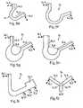
- the schematically illustrated ultrasonic device according to FIG. 1is suitable for use as a handheld device. It includes, in a manner known per se, in a housing 1 a piezoelectric quartz, not shown, and transmission means for transmitting a vibration thereof to a vibration exciter 2.
- the housinghas an elongated basic shape, which is typical for instruments for dental use.
- a handle 3is still indicated schematically.
- a drive and excitation electronics 4which provides an output voltage which sets the piezoelectric oscillator quartz with the desired frequency and amplitude in vibration.
- a sonotrode 5which serves to deflect the mechanical vibrations which are picked up at the vibration exciter 2.
- a vibration pick-up point 5.1 of the sonotrodeis vibrated by the vibration exciter along a first axis 6.1, this generates a vibration of a vibration delivery point 5.2 along a second axis 6.2, which forms an angle ⁇ (deflection angle) to the first axis 6.1.
- a dental implant 7serving as an intermediate or connector plastic element 8 (eg. Made of PEEK, a high mechanical and thermal strength plastic).
- an intermediate or connector plastic element 8eg. Made of PEEK, a high mechanical and thermal strength plastic
- the sonotrodemay be rotatable about its first axis 6.1, which, for example, makes sense if the ultrasound device is not substantially cylindrical as shown, but has another, not cylindrically symmetrical shape.
- a first example of a specific embodiment of the inventive sonotrode 5shows FIG. 2 ,
- the fastenerincludes a threaded pin 11. This is delimited to a transition region 12 through a collar 13.
- the oscillating element 14is coupled to the transition region 12 at a front end by a connecting joint 15.
- the oscillation delivery pointcoincides with the decoupling point 14.2, at which the oscillation element has a coupling pin 16, to which - possibly via an intermediate piece - a workpiece (for example an implant) or a tool can be coupled.
- the vibrationcorresponds to a longitudinal vibration of the threaded pin - is excited via the joint 15, which defines the Einkoppeltician 14.1, a transverse vibration of the vibrating element at the coupling point.
- the resultis a (fundamental) oscillation, in which the first arm 14.3 and the second arm 14.4 of the V-shaped oscillating element oscillate in the manner of a tuning fork against each other. Due to the action of the hinge-like hinge 15, this vibration is not accompanied by a corresponding vibration of the vibrating mass center of mass, but rather the first arm can "tip" up or down from the transition region so that a neutral point 14.5 remains approximately stationary in the vibration.
- the angle between the longitudinal direction of the vibrating element at the coupling point 14.1 and the longitudinal direction at the coupling pointis 110 °, i. the angle between the two arms 14.3, 14.4 about 70 °.
- the cross-sectional shape (in a cross section perpendicular to the longitudinal direction) of the vibrating elementis approximately rectangular and such that the element has a greater width in the direction perpendicular to the plane of the drawing than in the other direction. This helps to suppress vibrations perpendicular to the vibrating element plane.
- the embodiment of the sonotrode according to FIG. 3ais different from that of FIG. 2 in that the joint 15 does not adjoin the end face but laterally to the vibrating element. This makes a more compact design possible, since the transition region of the sonotrode according FIG. 2 can be omitted.
- the joint 15is almost pushed by a longitudinal vibration (in the direction of the arrow 17) of the fastener 11. But it has a similar one Effect as in FIG. 2 that is, it allows tilting of the vibrating element, whereby the neutral point 14.5 can remain approximately stationary in the vibration.
- FIG. 4is similar to that of FIGS. 3a and 3b but differs from this in that the sonotrode 5 is not integral, but the fastener 11 is separate from the vibrating element and by a dacaselment, for example, a screw (not shown) can be coupled to this. Visible in the figure are a through hole 21 for the screw in the oscillating element and a corresponding blind hole 22 in the fastener 11. Depending on the elasticity of the screw material, the threaded connection can be substantially solid or it can also act as a joint, as will be explained below ,
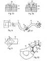
- the vibration excitationtakes place "in axis" - ie the elements between the vibration exciter 2 and the vibrating element 14 are all on a common axis - are also alternative possibilities conceivable.
- Such an alternative optionis very schematic in FIG. 16 illustrated.
- the fastening elementhas an L-shape, so that the attachment point of the oscillating element 14 - formed by the hinge 15 - is arranged offset from the axis.
- thiscan be advantageous depending on the application - has the consequence that the transition region 12 can be set relative to the threaded pin 11 in tilting vibrations. These may have an impact on system resonances and on the amplitude at the vibration delivery location.
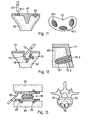
- FIGS. 5a to 5iare very schematically drawn possible forms of vibrating elements of a sonotrode according to the invention.
- the oscillating elementscan be fastened to any fastening elements or directly to the vibration exciter, if necessary via joints, or be integrally formed with the fastening elements. You can have different coupling devices. In all vibrating elements is assumed that a deflection angle of about 100 ° -120 °; appropriate modifications for other angles are of course possible and obvious.
- the vibrating element 14 according to FIG. 5ais arcuate, ie curved over its entire length, the angle of curvature may be constant, but need not be constant.
- Also of the vibrating element according to FIG. 5bis arcuate. It differs from the one according to FIG. 5a in that the decoupling point 14.2 lies on the inside, which is why the bending angle is 180 ° minus the deflection angle.
- the oscillating elementis curved toward the workpiece, tool or intermediate piece.
- the decoupling pointis in each case on the outside; Modifications in the case of an inner decoupling point but are possible in each of the drawn cases. If the deflection angle should be in the range between 190 ° and 130 °, such a modification with a change in the bending angle is between 50 ° and 80 ° associated. Overall, a generally interesting range of bending angles between 50 ° and 130 ° results.
- the vibrating element according to FIG. 5cis V-shaped, ie at the bent portion 14.6 connect two arms 14.3, 14.4.
- the two armscan, but need not have the same dimensions (length, cross-sectional area or cross-sectional area profile) and the same configuration (cross-sectional shape, surface finish, etc.).
- FIG. 5dshows an omega-shaped vibrating element while FIG. 5e represents a hook-shaped vibrating element.
- the hook-shaped vibrating elementcan be considered as a combination of the concepts of an omega-shaped sliding element (first arm 14.3) with a V-shaped vibrating element (second arm 14.4). In general, such combinations are possible, ie also arcuate-V-shaped, arcuate-omega-shaped, etc.
- a vibrating elementwhich can be considered as an intermediate solution between an omega-shaped and a V-shaped vibrating element.
- Such a vibrating elementacts similar to a V-shaped vibrating element, but it is voltage-optimized.
- FIG. 5gshows a variant of the vibrating element of FIG. 5f , wherein the thickness (ie the cross-sectional area) in the bent portion 14.6 is increased in comparison to the arms 14.3, 14.4.
- Such a vibrating elementis slightly stiffer than that of FIG. 5f , thus has a higher natural frequency for given material properties.
- the vibrating element of FIG. 5his also a variant of that of FIG. 5f , wherein the two arms 14.3, 14.4 have different thicknesses and therefore also different masses. If, as drawn, the arm 14.3 with the coupling point has the larger mass, the vibrating element causes an amplification of the amplitude.
- the vibrating element 14 of Fig. 5jhas between a central portion 14.12 and the two arms 14.3, 14.4 each a hinge-like constriction 14.11, 14.2.
- the constrictionsreduce the rigidity of the vibrating element as a whole and therefore set at the same size compared to a vibrating element as in Fig. 5c the resonance frequency and thus, depending on the operating parameters, also the optimal working frequency down. It is also possible, according to a vibrating element Fig. 5j to dimension comparatively smaller. As a result, it is possible to design the vibrating element in such a way that, for the same materials, the resonant frequency is in a similar range as in a larger vibrating element according to FIG Fig. 5c , A reduced rigidity of the vibrating element is thus a way to miniaturize the vibrating element and thus the entire device.
- FIGS. 6a to 6dshow examples of coupling elements.
- a decoupling point-side arm of a vibrating element 14is drawn in two different views and sectional views.
- FIG. 6aThe coupling according to FIG. 6a is effected by the interaction of a coupling pin 16 with a corresponding recess 8.1 in the connecting piece 8.
- the reverse arrangementshows FIG. 6b .
- This type of couplingis simple to manufacture and allows for easy coupling, but is prone to angular error and not rotationally secure. If instead of a circular cylindrical pin another non-rotationally symmetrical pin is used - it can be a polygonal, elliptical, star-shaped etc. cross section be chosen - is one too Fig. 6a respectively.
- Fig. 6banalog coupling rotationally symmetric.
- FIG. 6c RemedyA ball element 32 of the connecting piece 8 cooperates with a joint socket-like recess 14.8 of the oscillating element.
- This type of connectionis also not twist-proof.
- FIG. 6dshows.
- the connecting piece 8has a non-cylindrically symmetrical ball element 33, which cooperates with a corresponding recess 14.9 of the vibrating element.
- the variants according to FIGS. 6c and 6dcan of course be configured in the reverse order.
- Other coupling variantsare conceivable, for example. With slightly conical pin etc.
- a couplingmay also include separate means by which tensile forces can be transmitted to the tool, workpiece or adapter. This may be necessary in embodiments where a firm connection between the device and the tool, workpiece or adapter is desired and in which the friction and / or clamping forces of the above coupling means are not sufficient.
- Such separate meansmay in a conventional manner transverse to the direction of vibration, each engaging behind elements, for example. In the manner of a bayonet lock or in another known per se.
- FIGS. 7a to 7eare very schematically drawn different embodiments of connections between a fastener 11 (or, as an alternative for non-one-piece embodiments, the vibration exciter) and the vibrating element 14.
- the joint 15 according to Figure 7acorresponds to that already discussed above.
- FIG. 7bshows a variant of it.
- the jointis formed by an inhomogeneity of the material at the transition between the fastening element 11 and vibrating element 14:
- the sonotrodeconsists of a material with a smaller elasticity module compared to the oscillating and fixing element.
- the connectionis a screw connection (as in FIG.
- connectioncan be made in other comparable manner, for example.
- a bayonet connectionshows a variant of a screw with a non or not substantially expandable screw and a compressible spring element 43, which may be attached, for example, to the screw.
- another connection meansis conceivable instead of a screw.
- the part of the deviceis called, which has an elongated shape as a whole, is bent and performs the actual oscillation - analogous to the two arms of a tuning fork.
- the decoupling pointis the point at which the vibration is picked up by the vibrating element. In all the illustrated embodiments, the vibration delivery point coincides with the outcoupling point. This is not a necessary requirement.
- the sonotrodefor example, between the decoupling point and the oscillation discharge point have a transition element which has any geometric shape and through which the vibrations, for example, are transmitted as longitudinal oscillations from the decoupling point to the oscillation discharge point.
- the coupling deviceis then generally present at the end of the transition element remote from the oscillating element.
- Such a transition elementmay, for example, the shape of a fixedly connected to the vibrating element rod and allow attachment of the device in recessed places.
- the coupling-in point and the coupling-out pointare each near the ends of the vibrating element. This is not a necessity. Rather, for example, the amplitude of the decoupled oscillation can be influenced by the selection of the decoupling point. This is exemplified in Fig. 5i outlined by double arrows.
- the coupling pointcan also be moved along the first arm and, in addition, a counterweight can be present distally from the decoupling point, which can be used to influence the amplitude and resonance frequency Fig. 5i the decoupling point at the point 14.2 '' set, the extra mass acts as such counterweight).
- a counterweightcan also be provided distally from the coupling point.
- FIG. 8is schematically drawn an arrangement with two devices (sonotrodes) of the inventive type, which together form a means for deflecting mechanical vibrations.
- the first sonotrode 5is not in direct contact with the workpiece or connecting piece 8 but serves as a transition piece (converter), which deflects the vibrations picked up at the vibration exciter 2 by a first deflection angle and couples them into the second sonotrode 5 '.
- Thisis also designed according to the invention and thus deflects the vibrations by a second angle of deflection.
- the first deflection anglecan be the same amount as the first deflection angle, or the two deflection angles can be different.
- connection between the first and the second sonotrodecan be fixed according to a first alternative.
- the orientation of the second sonotrode relative to the firstcan also be influenced.
- connectioncan be movable and the relative orientation of the sonotrodes can be changed in situ.
- the second sonotrodecan be rotatable about the second axis 6.2 of the first sonotrode.
- a rotary devicewhich can be operated by the ultrasound device.
- Suchmay in a conventional manner force and / or Drehmomentumlenk Anlagenen (cables, etc.) have, for example, are set by an electric drive or possibly by hand in operation.
- drive means of the rotary devicecan also act directly at the location of the coupling between the first and the second sonotrode.
- a vibrationcan be triggered, which causes a rotation of the second sonotrode, similar to the principle of a piezoelectric motor.
- FIG. 9an alternative embodiment of a coupling is shown, in which a coupling pin 16 of a sonotrode and the corresponding recess of the other sonotrode are not rotationally symmetrical, but, for example, in cross-section polygonal-shaped.
- a coupling pin 16 of a sonotrode and the corresponding recess of the other sonotrodeare not rotationally symmetrical, but, for example, in cross-section polygonal-shaped.
- Such a couplingallows the two sonotrodes to be arranged relative to one another in a discrete number of defined orientations. In an orientation once selected, the two sonotrodes are fixed, an adjustment of the orientation is possible only ex situ by removing the coupling pin 16 of a sonotrode from the corresponding recess of the other sonotrode and re-introducing in a different orientation.
- FIG. 10shows a method in which the inventive sonotrode and also the device for deflecting mechanical vibrations can be used.
- Drawn very schematically and in sectionsis a pelvic bone 51, in which an artificial hip joint socket 52 is inserted. This is done with a plurality of implants 53, which according to the in the writings WO 02 / 069,817 and WO 2004/017857 described principle are configured.
- the acetabulumis placed according to known methods. Subsequently, implants of the type mentioned are guided through openings provided for this purpose and anchored by liquefaction of thermoplastic or thixotropic material on its surface by application of mechanical vibrations in the porous bone material.
- implantsprior to application of the mechanical vibrations, bores may be made in the bone, so that insertion of the implants can be done with little effort.
- the implantsmay be designed so that upon application of mechanical vibrations on the proximal side forms a kind of head, through which the artificial acetabulum is fixed.
- a prefabricated headmay also be present, and / or infiltration of thermoplastic material of the implant into a porous surface portion of the acetabular cup may occur.
- the acetabulummay have plastic areas, and there is a welding of these areas with areas of the implant.
- the advantages of the inventioncome into their own especially well: the various implants must be driven into the bone at different angles. By deflecting the mechanical vibrations with a sonotrode according to the invention, this is very easy to do. Particularly advantageous is the use of a device according to FIG. 9 in particular when the second sonotrode can be rotated by the user in situ, ie without the apparatus having to be removed from the surgical site, by a rotating device relative to the first one.
- FIG. 11shows the fixation of a tibial plateau implant 61 according to a first variant.
- the tibial plateau implant 61has predefined open-pored porous zones 61.1. It is brought in a first step by means of methods known per se in its final position on the tibial bone 62. Subsequently, a (thermoplastic or possibly thixotropic) polymer is introduced through the porous zones 61.1, which is done by applying a trained as a polymer body preparation 63 with mechanical vibrations and simultaneous pressing against the porous zones. In addition to the porous zones, the polymer also infiltrates the bone, thus providing primary stability. The porous zones are subsequently beneficial in osseointegration and allow the tibial plateau implant to well grow into the bone.
- FIG. 11analogous procedure - introducing a polymer preparation through porous zones - can also be used if a joint socket can be attached to the bone.
- a tibial bone 62is drawn with the tibial plateau implant 71 before the implantation of a second implant 73; on the right, a cutout with an implanted implant is shown.
- the tibial plateau implantis first placed in its final position by methods known per se, including tibial bone surgery.
- implants 73whose surfaces at least partially have a therastic or thixotropic polymer 73.1, are driven through prefabricated openings 71.1 of the tibial plateau implant into the bone.
- pre-drilling in the bonecan optionally be carried out beforehand.
- the implants 73may be designed so that when applied with mechanical vibration on the proximal side forms a kind of head, through which the artificial tibial head is fixed.
- a prefabricated head 73.2may also be present, and / or infiltration of thermoplastic material of the implant into a porous surface portion of the artificial tibial head may occur, or the implant may be partially welded to the latter.
- the implanthas a hard core 73.3, eg. Of titanium or other suitable non-deformable material.
- the tibial headis like during an operation like those FIGS. 11 and 12 accessible from the side, mechanical vibrations and the pressure but must be applied from above or diagonally above. For this reason, the use of an inventive, mechanical vibrations to a deflecting deflecting sonotrode is particularly advantageous here. Also a device according to FIG. 9 can be used.
- FIG. 13 Figure 1shows the fixation of an artificial disc (ie an intervertebral disc implant) to the vertebral bodies of the two adjacent vertebral bones.
- a disc implant 81a standard disc implant can be used. This is placed first with known methods between the vertebral bodies. Implants 82 are connected with the method according to the documents WO 02 / 069,817 and WO 2004/017857 introduced to secure the implant. Polymer material infiltrated by mechanical vibration infiltrates porous material of the vertebral bone 83 and according to a first variant also porous Material of the intervertebral disc implant 81.
- the polymer material of the implant 82fuses superficially with intervertebral disc implant material in the manner of an ultrasonic welding.
- the fixation of the intervertebral disc implant as mentioned in the embodiments described above by means of a (recessed) head, which is preformed or forms during insertiontakes place.
- the deflection of mechanical oscillations by the device according to the invention and possibly by the device according to the inventionis of great advantage since the implants 82 are driven into the bone at a location which is very difficult to access and at an angle.
- Figure 91shows a plate 91 which can be attached to two vertebral bones and used to stabilize the spine.
- the plateis at least partially made of elastic material and can be symbolized as symbolized by the double arrow and stretched, with the middle part deformed. It is preferably fixed by implants 92 which are not circular in cross-section, resulting in complete mechanical stability, even if a total of only two implants 92 are used for attachment.
- implants 92which are not circular in cross-section, resulting in complete mechanical stability, even if a total of only two implants 92 are used for attachment.
- the surgical procedures shown in the preceding figuresmay in particular be minimally invasive.
- the implants shown in the preceding figuresare all based on the principle that on their surface at least partially thermoplastic material is present, which is liquefiable in contact with hard tissue by mechanical vibrations.
- the implants - or at least one of them -also have a non-liquefiable by the mechanical vibration sleeve having a plurality of openings, wherein liquefiable material is present in the interior of the sleeve, which is liquefied during the implantation process by the mechanical vibrations and through the openings in the sleeve is pushed outwards and the porous structures of the hard tissue interpenetriert.
- Such implantsare also known from the prior art, for example WO 02 / 069,817 ,
- a protective housing 101When using devices according to the invention for surgical, dental or orthodontic procedures, it may be desirable to shield tissue parts from the mechanical vibrations in order to avoid secondary damage.
- the protective housingmay be designed so that it can be plugged by first guide means - here by a first opening 101.1- directly on the housing of the vibration generating device, so that the Relative position of sonotrode 5 and protective housing 101 is determined by it and no time-consuming vibration-isolating mounting of the sonotrode in the protective housing is necessary.
- the sonotrodeIn the non-operating state, the sonotrode can be held in place relative to the housing by fixing means, from which it is coupled end in the operating state, wherein the decoupling can, for example, be effected by plugging on the sonotrode.
- the protective housing on second guide meanswith which holding means for the tool, workpiece or adapter can be performed.
- theseare formed by a second opening 101.2.
Landscapes
- Health & Medical Sciences (AREA)
- Orthopedic Medicine & Surgery (AREA)
- Life Sciences & Earth Sciences (AREA)
- Animal Behavior & Ethology (AREA)
- Public Health (AREA)
- Veterinary Medicine (AREA)
- General Health & Medical Sciences (AREA)
- Transplantation (AREA)
- Engineering & Computer Science (AREA)
- Oral & Maxillofacial Surgery (AREA)
- Biomedical Technology (AREA)
- Heart & Thoracic Surgery (AREA)
- Epidemiology (AREA)
- Dentistry (AREA)
- Cardiology (AREA)
- Vascular Medicine (AREA)
- Physical Education & Sports Medicine (AREA)
- Surgery (AREA)
- Nuclear Medicine, Radiotherapy & Molecular Imaging (AREA)
- Molecular Biology (AREA)
- Medical Informatics (AREA)
- Mechanical Engineering (AREA)
- Neurology (AREA)
- Apparatuses For Generation Of Mechanical Vibrations (AREA)
- Surgical Instruments (AREA)
- Prostheses (AREA)
- Dental Tools And Instruments Or Auxiliary Dental Instruments (AREA)
- Piezo-Electric Or Mechanical Vibrators, Or Delay Or Filter Circuits (AREA)
- Inductance-Capacitance Distribution Constants And Capacitance-Resistance Oscillators (AREA)
- Gyroscopes (AREA)
- Glass Compositions (AREA)
- General Induction Heating (AREA)
- Manufacturing Cores, Coils, And Magnets (AREA)
Abstract
Description
Translated fromGermanDie Erfindung betrifft die Applikation von mechanischen Oszillationen, bspw. Ultraschalloszillationen, in Situationen, in denen beschränkte Platzverhältnisse die Bewegungsfreiheit einschränken. Sie betrifft speziell eine Vorrichtung zum Umlenken von mechanischen Schwingungen, insbesondere eine Sonotrode oder ein Kopplungsstück.The invention relates to the application of mechanical oscillations, for example ultrasonic oscillations, in situations in which limited space constrains freedom of movement. It relates in particular to a device for deflecting mechanical vibrations, in particular a sonotrode or a coupling piece.
Ultraschall-Bearbeitungsgeräte werden heute vermehrt auch im medizinischen Sektor, unter anderem in der Zahnmedizin angewandt. Ein Beispiel für eine Anwendung von Ultraschallgeräten in der Medizin, insbesondere Zahnmedizin, ist ein neu entwickeltes Verfahren zum Verankern von Implantaten und Präparaten in porösem Gewebe. Das Verfahren ist beispielsweise in den Schriften
Ultraschall-Bearbeitungsgeräte für den medizinischen Gebrauch haben praktischerweise oft eine längliche Form mit Handgriff, so dass sie ähnlich einem Zahnarztbohrer in der Art eines Handwerkzeuges verwendet werden können. Der beispielsweise piezoelektrische Schwingungsanreger regt eine Sonotrode zu longitudinalen Schwingungen an, die diese an ein Werkzeug oder Werkstück überträgt. Aufgrund der länglichen Form des Geräts ist aber die Arbeit an schwer zugänglichen Orten erschwert.Practically, ultrasound processing devices for medical use often have an elongated shape with a handle, so that they can be used similar to a dental drill, such as a hand tool. The example piezoelectric vibration exciter excites a sonotrode to longitudinal vibrations, which transmits them to a tool or workpiece. Due to the elongated shape of the device but the work is difficult in hard to reach places.
Aus der
Ein dazu alternatives Vorgehen für das Umlenken von Ultraschall ist in der
Es ist demnach eine Aufgabe der Erfindung, eine Lösungen für das Umlenken von mechanischen Schwingungen zur Verfügung zu stellen, welche Nachteile von Ansätzen gemäss dem Stand der Technik überwindet und welche insbesondere geeignet für den Einsatz bei beschränkten Platzverhältnissen sein soll.It is therefore an object of the invention to provide a solution for redirecting mechanical vibrations which overcomes the disadvantages of prior art approaches and which is particularly suitable for use in limited space.
Besonders bevorzugt sind Lösungen, die ein Umlenken zwischen einer Schwingungs-Aufnahmestelle und einer Schwingungs-Abgabestelle um ungefähr 100°-130° ermöglichen, weil bei diesen Winkeln die Arbeit an schwer zugänglichen Stellen oft besonders leicht fällt.Particularly preferred are solutions that deflect approximately between a vibration receiving location and a vibration delivery location 100 ° -130 °, because at these angles working in hard to reach places is often particularly easy.
Diese Aufgabe wird gelöst durch die Erfindung, wie sie in den Patentansprüchen definiert ist.This object is achieved by the invention as defined in the patent claims.
Eine erfindungsgemässe Vorrichtung zum Umlenken von mechanischen Schwingungen, ist an einer Schwingungs-Aufnahmestelle längs einer ersten Achse in Schwingung versetzbar und überträgt eine solche Schwingung in eine Schwingung längs einer zweiten Achse an einer Schwingungs-Abgabestelle, wobei die erste und die zweite Achse einen Winkel zueinander bilden. An der Schwingungs-Aufnahmestelle ist die Vorrichtung zum Anschliessen eins Schwingungsanregers, an der Schwingungs-Abgabeststelle zum Anschliessen eines Werkzeugs, Werkstücks oder Zwischenstücks ausgebildet. Die Vorrichtung zeichnet sich im Wesentlichen dadurch aus, dass sie ein längliches, zwischen zwei Enden gebogenes Schwingelement aufweist, an dem ein Einkoppelpunkt und ein Auskoppelpunkt angeordnet sind, wobei die Vorrichtung so ausgebildet ist, dass das Schwingelement am Einkoppelpunkt und am Auskoppelpunkt transversal schwingt, wenn die Schwingungs-Aufnahmestelle mit einer Schwingung beaufschlagt wird.An inventive apparatus for deflecting mechanical vibrations is oscillatable at a vibration receiving location along a first axis and transmits such vibration into vibration along a second axis at a vibration delivery location, the first and second axes at an angle to each other form. At the vibration receiving location, the device for connecting a vibration exciter is formed at the vibration delivery point for connecting a tool, workpiece or intermediate piece. The device is characterized essentially by the fact that it has an elongated, bent between two ends of the vibrating element, on which a Einkoppelpunkt and a decoupling point are arranged, wherein the device is designed so that the oscillating element at the coupling point and the decoupling point transversely oscillates, if the vibration receiving location is acted upon by a vibration.
Die mechanischen Schwingungen sind bspw. Ultraschallschwingungen.The mechanical vibrations are, for example, ultrasonic vibrations.
Die erfindungsgemässe Vorrichtung wirkt gemäss obiger Lehre also als Sonotrode, wobei der Begriff "Sonotrode" nicht bedeutet, dass die Vorrichtung direkt am Werkzeug oder Werkstück angreifen muss; vielmehr kann auch ein Zwischenstück vorhanden sein, das die Schwingungen von der Sonotrode an ein Werkzeug oder Werkstück oder ein weiteres Zwischenstück weiter überträgt.According to the above teaching, the device according to the invention thus acts as a sonotrode, wherein the term "sonotrode" does not mean that the device has to act directly on the tool or workpiece; Rather, an intermediate piece may be present, which transmits the vibrations from the sonotrode to a tool or workpiece or another intermediate piece on.
Dadurch, dass die Schwingungen vom Schwingelement transversal abgegriffen werden, wirkt das Schwingelement in der Art eines "Hammers", der einen in Bezug auf die Schwingelement-Achse seitliches Werkzeug, Werkstück oder Zwischenstück mit den Schwingungen beaufschlägt.Characterized in that the vibrations are tapped transversely from the vibrating element, the vibrating element acts in the manner of a "hammer", which acts on a vibration with respect to the vibrating element axis lateral tool, workpiece or adapter.
Es hat sich gezeigt, dass es mit erfindungsgemässen Vorgehen möglich ist, am Auskoppelpunkt Schwingungen mit einer guten Linearität zu erzeugen, d.h. Schwingungen deren Komponente quer zur gewünschten (in Bezug auf das Schwingelement transversalen) Schwingungsrichtung sehr klein ist. D.h. es ist möglich Schwingungen zu erzeugen, die entlang einer sehr langgestreckt-elliptischen Bahn verlaufen, so dass in sehr guter Näherung von durch Schwingungen entlang einer Gerade ausgegangen werden kann.It has been found that it is possible with the inventive method to produce vibrations with good linearity at the decoupling point, i. Vibrations whose component is very small transversely to the desired (transversely with respect to the vibrating element) vibration direction. That it is possible to generate vibrations that run along a very elongated-elliptical path, so that can be assumed in a very good approximation of by vibrations along a straight line.
Zwischen der Vorrichtung und dem Werkzeug, Werkstück oder Zwischenstück - und auch zwischen dem Schwingungsanreger und der Vorrichtung - kann eine feste, lösbare Kupplung vorhanden sein. Eine solche hat zur Folge, dass das Werkzeug, Werkstück oder Zwischenstück die Schwingung an der Schwingungs-Abgabestelle voll mitmacht, d.h. dass jeweils beide Halbwellen übertragen werden. Als Alternative kann die Übertragung auch durch einen nur losen Kontakt erfolgen, wobei dann nur Druck- und keine Zugkräfte übertragbar sind.Between the device and the tool, workpiece or adapter - and also between the vibration exciter and the device - may be present a fixed, releasable coupling. Such has the consequence that the tool, workpiece or adapter fully participates in the vibration at the vibration delivery location, i. that both half-waves are transmitted in each case. As an alternative, the transmission can also be effected by a loose contact, in which case only pressure and no tensile forces can be transmitted.
Die länglich-gebogene Ausgestaltung des Schwingelementes bedeutet, dass eine Längsachse und damit eine longitudinale Richtung und transversale Richtungen definiert sind. Das Schwingelement kann bspw. die Form eines gebogenen Stabes beliebigen Querschnitts aufweisen, wobei die Querschnittsfläche des Stabes über seine Länge nicht konstant sein muss. Der Ein- und der Auskoppelpunkt können sich je in der Nähe eines Endes des Stabes befinden. Am Stab können zusätzliche Elemente befestigt sein, bspw. Massen, mit denen das Amplitudenverhältnis zwischen Schwingungen am Einkoppel- und am Auskoppelpunkt beeinflussbar ist.The elongated-bent configuration of the vibrating element means that a longitudinal axis and thus a longitudinal direction and transverse directions are defined. The oscillating element can, for example, have the shape of a bent rod of any cross-section, wherein the cross-sectional area of the rod does not have to be constant over its length. The input and output points may each be near one end of the rod. At the bar can additional Be attached elements, for example. Masses with which the amplitude ratio between vibrations at the coupling and the decoupling point can be influenced.
Eine der Erfindung zu Grunde liegende Erkenntnis ist, dass die transversalen Schwingungen eines solchen Schwingelementes mit einem länglichen, gebogenen Abschnitt dafür geeignet sind, mechanische Vibrationen um verschiedene, durch die Wahl Geometrie des Schwingelementes fast frei wählbare Winkel umzulenken.One of the underlying findings of the invention is that the transverse vibrations of such a vibrating element with an elongated, curved portion are suitable for deflecting mechanical vibrations by different angles, which can be chosen almost freely by the choice of geometry of the vibrating element.
Bevorzugt verläuft das Schwingelement in einer Ebene und schwingt in dieser Ebene. Der Umlenk-Winkel wird bestimmt durch die Biegung des Schwingelementes in der Ebene sowie durch die Lage des Einkoppel- und des Auskoppelpunkts: Durch die Biegung in der Ebene wird eine Innen- und eine Aussenseite definiert. Falls der Auskoppelpunkt auf der Aussenseite liegt, entspricht der Umlenkwinkel dem Biegewinkel, also dem Winkel zwischen der Schwingelement-Längsachse am Einkoppel- und am Auskoppelpunkt. Falls sich hingegen der Auskoppelpunkt auf der Innenseite befindet ist der Umlenkwinkel 180° minus dem Biegewinkel.Preferably, the vibrating element extends in a plane and oscillates in this plane. The deflection angle is determined by the bending of the vibrating element in the plane and by the position of the coupling and decoupling point: By bending in the plane, an inner and an outer side is defined. If the decoupling point lies on the outside, the deflection angle corresponds to the bending angle, that is to say the angle between the oscillating element longitudinal axis at the coupling-in point and at the decoupling point. If, on the other hand, the decoupling point is on the inside, the deflection angle is 180 ° minus the bending angle.
Unter Umständen - im Allgemeinen weniger bevorzugt - ist auch ein Abgreifen der Schwingung am Schwingelement durch ein Objekt (Werkzeug, Werkstück oder Zwischenstück) möglich, welches stirnseitig am Schwingelement angebracht ist. Ein "aussenseitiger" Auskoppelpunkt bedeutet dann, dass das Werkzeug, Werkstück oder Zwischenstück während der Bearbeitung im Bezug auf die Biegung des Schwingelements aussen liegt, ein "innenseitiger Auskoppelpunkt umgekehrt dass es innen liegt.Under certain circumstances - generally less preferred - also a tapping of the vibration on the vibrating element by an object (tool, workpiece or adapter) is possible, which is mounted on the front side of the vibrating element. An "outboard" decoupling point then means that the tool, workpiece or adapter is outboard during machining with respect to the flexure of the vibrating element, an inward decoupling point, conversely, that it lies inside.
Durch die Wahl von Biegewinkel und Ein- und Auskoppelpunkten wird ein praktisch beliebiger Umlenkwinkel bei einer grossen Variabilität von äusseren Abmessungen ermöglicht. Im Unterschied zum Stand der Technik können seine äusseren Abmessungen für gegebene Umlenkwinkel, Frequenz und Leistung sowie ein gegebenes Amplitudenverhältnis innerhalb gewisser Randbedingungen gewählt werden, bspw. durch Wahl der Massenschwerpunkte von zwei Schwingelement-Hälften (entsprechend zwei Schwingelement-Armen), der Wahl von Einkoppel- und Auskoppelpunkt (innen/aussen) etc. Das Schwingelement kann bspw. zum Werkzeug, Werkstück oder Zwischenstück "hin" oder "davon weg" gebogen sein.The choice of bending angle and coupling and decoupling points allows a practically arbitrary deflection angle with a large variability of external dimensions. In contrast to the prior art, its external dimensions for given deflection angle, frequency and power as well as a given amplitude ratio can be selected within certain boundary conditions, for example by selecting the center of gravity of two vibrating element halves (corresponding to two vibrating element arms), the choice of coupling - And decoupling point (inside / outside), etc. The oscillating element may, for example, to the tool, workpiece or adapter "out" or "away" bent.
Besonders bevorzugt ist der Fall, in welchem der Biegewinkel mehr als 90° beträgt und sowohl Ein- als auch Auskoppelpunkt auf der Aussenseite liegen. Das ist aus Platzgründen für die meisten Anwendungsgeometrien besonders günstig; ein Biegewinkel von mehr als 90° hat sich auch schwingungstechnisch als besonders günstig herausgestellt.Particularly preferred is the case in which the bending angle is more than 90 ° and both input and Auskoppelpunkt are on the outside. This is particularly favorable for space reasons for most application geometries; a bending angle of more than 90 ° has also turned out to be particularly favorable in terms of vibration technology.
Der bevorzugte Umlenkwinkel ist zwischen 100° und ca. 130°, besonders bevorzugt 110° bis 120°. Die Erfindung erlaubt auch Umlenkwinkel, die keine ganzzahligen Teiler von 360° sind.The preferred deflection angle is between 100 ° and about 130 °, more preferably 110 ° to 120 °. The invention also allows deflection angles which are not integer divisors of 360 °.
Das Schwingelement kann bspw. eine Form aufweisen, die im Wesentlichen einem Kreisbogen-Ausschnitt entspricht, es kann V-förmig, Ω-förmig, hakenförmig etc. sein. In Ausführungsformen, bei denen nicht das ganze Schwingelement gleichmässig gekrümmt ist, sondern bei denen die Krümmung in einem Krümmungsbereich besonders stark ist (bspw. bei der V- oder Ω-form), müssen nicht beide an den Krümmungsbereich anschliessenden Arme gleich lang sein, sondern das Schwingelement kann eine asymmetrische Form aufweisen. Auf jeden Fall bildet das Schwingelement keinen geschlossenen Ring sondern quasi einen offenen Ring gleichmässiger oder ungleichmässiger Krümmung. Das ist in mehrerer Hinsicht vorteilhaft. Einerseits sind aufgrund der nicht-geschlossenen Konstruktion viel grössere Amplituden möglich als bei einer ringförmigen Sonotrode. Andererseits gibt es bei einer ringförmigen Sonotrode zwischen Knoten der Schwingung mehrere Abschnitte, die schwingen. In der Anwendung wird aber im Allgemeinen nicht die Schwingung jedes solchen Abschnittes benutzt. Die Leistung, die zum In-Schwingung-Versetzen eines nicht benutzten Abschnittes benötigt wird, geht also verloren. Aus diesem Grund ist der Wirkungsgrad der erfindungsgemässen Konstruktion im Allgemeinen höher als einer ringförmigen Sonotrode gemäss dem Stand der Technik. Schliesslich ist die nicht-ringförmige Konstruktion auch vorteilhaft, weil sich wie erwähnt praktisch beliebige Umlenkwinkel realisieren lassen und der Platzbedarf geringer ist.The oscillating element may, for example, have a shape which substantially corresponds to a circular arc cutout, it may be V-shaped, Ω-shaped, hook-shaped, etc. In embodiments in which the entire oscillating element is not uniformly curved, but in which the curvature is particularly strong in a curvature region (for example in the V or .OMEGA. Shape), it is not necessary for both arms adjoining the curvature region to have the same length the vibrating element may have an asymmetrical shape. In any case, the vibrating element does not form a closed ring but virtually a open ring of uniform or uneven curvature. This is advantageous in several ways. On the one hand, due to the non-closed construction, much larger amplitudes are possible than with an annular sonotrode. On the other hand, with an annular sonotrode between nodes of vibration, there are several sections that vibrate. In the application, however, the vibration of each such section is generally not used. The power needed to vibrate an unused section is lost. For this reason, the efficiency of the inventive construction is generally higher than a ring-shaped sonotrode according to the prior art. Finally, the non-annular construction is also advantageous, because as mentioned virtually any deflection can be realized and the space required is less.
Der Querschnitt des Schwingelementes muss nicht homogen sein, sondern kann im Gegenteil variieren. Solche Variationen des Querschnitts oder der Armlängen können ebenso wie die Materialwahl, Querschnittsprofile, Form des Schwingelementes und Massenverteilung sowie die Positionen des Einkoppelpunktes und des Auskoppelpunktes und eventuelle Ausgestaltung von Gelenken, Zusatzelementen etc. dazu benutzt werden, die Form, Eigenfrequenzen und Amplitudenverhältnisse der Eigenschwingung zu beeinflussen. Bspw. kann eine Amplitudenverstärkung oder -abschwächung durch eine Wahl der Massenverteilung zwischen zwei Armen bewirkt werden.The cross section of the vibrating element does not have to be homogeneous, but on the contrary can vary. Such variations of the cross-section or the arm lengths, as well as the choice of materials, cross-sectional profiles, shape of the vibrating element and mass distribution and the positions of Einkoppelpunktes and Auskoppelpunktes and eventual design of joints, additional elements, etc. can be used to the shape, natural frequencies and amplitude ratios of the natural oscillation influence. For example. For example, amplitude amplification or attenuation may be effected by a choice of mass distribution between two arms.
Das Schwingelement kann bspw. ähnlich der beiden Arme einer Stimmgabel ausgebildet sein, wobei die beiden Arme des Schwingelementes im Unterschied zu Stimmgabeln, die für das Stimmen von Musikinstrumenten verwendet werden, nicht parallel zueinander verlaufen, sondern in einem der Aufgabe angepassten Winkel.The oscillating element may be formed, for example, similar to the two arms of a tuning fork, wherein the two arms of the vibrating element, in contrast to tuning forks, which are used for the tuning of musical instruments, not parallel to each other, but at an angle adapted to the task.
Das Schwingelement ist am Einkoppelpunkt beispielsweise elastisch mit einem Schwingungsanreger des Schwingungen erzeugenden Geräts - bspw. Ultraschallgeräts - verbunden. Eine elastische Verbindung bedeutet, dass die Steifigkeit der Verbindung (genauer: deren Federkonstante) kleiner ist als die Steifigkeit des Schwingelementes selbst und auch kleiner als diejenige anderer Komponenten der Vorrichtung.The oscillating element is connected to the coupling point, for example elastically with a vibration exciter of the vibration generating device - eg. Ultrasonic device - connected. An elastic connection means that the rigidity of the connection (more precisely: its spring constant) is smaller than the rigidity of the oscillation element itself and also smaller than that of other components of the device.
Eine elastische Verbindung zwischen dem Schwingungsanreger und dem Schwingelement erlaubt, dass sich eine der Eigenschwingung entsprechende Schwingung mit der Anregungsfrequenz ausbildet, ohne dass sich der Massenschwerpunkt des Schwingelementes - also sozusagen das Schwingelement als Ganzes - während einer Auslenkung wesentlich verschieben müsste. Das wirkt sich positiv auf den Wirkungsgrad aus, da weniger grosse Massen beschleunigt werden müssen.An elastic connection between the vibration exciter and the vibrating element allows a vibration corresponding to the natural vibration to form with the excitation frequency without the mass center of gravity of the vibrating element-that is to say the vibrating element as a whole-shifting substantially during a deflection. This has a positive effect on the efficiency, since less large masses must be accelerated.
Die Verbindung zwischen dem Schwingungsanreger und dem Schwingelement kann gemäss einer ersten bevorzugten Ausführungsform ein Gelenk, bspw. elastisches Gelenk aufweisen. Dieses wirkt bspw. scharnierartig, d.h. es erlaubt Kippbewegungen in einer Richtung, nicht aber in der Richtung senkrecht dazu. Das Gelenk kann am stirnseitigen Ende des Schwingelementes oder seitlich (lateral) angebracht sein. Es ist vorzugsweise einstückig mit dem Schwingelement und einem Befestigungselement ausgebildet und kann die Form einer Einschnürung haben, durch welche die Materialdicke lokal so reduziert ist, dass das Gelenk Verschwenkungen in der Schwingelement-Ebene zulässt, nicht jedoch senkrecht dazu.The connection between the vibration exciter and the vibrating element can according to a first preferred embodiment have a joint, for example an elastic joint. This acts, for example, hingedly, i. It allows tilting in one direction, but not in the direction perpendicular to it. The joint may be attached to the front end of the vibrating element or laterally (laterally). It is preferably formed integrally with the oscillating element and a fastening element and may have the shape of a constriction, by which the material thickness is locally reduced so that the joint allows pivoting in the vibrating element level, but not perpendicular thereto.
Das Befestigungselement, welches die Vorrichtung optional aufweisen kann, dient dazu, das Schwingelement an den Schwingungsanreger zu koppeln. Es kann bspw. als Gewindezapfen ausgebildet und direkt auf den Schwingungsanreger aufschraubbar sein. Falls das Befestigungselement mit einem Scharnier und dem Schwingelement einstückig ausgebildet ist, weist die Vorrichtung unter Umständen nur ein einziges Bauteil auf, was auch für die Handhabung und unter herstellungstechnischen Gesichtspunkten vorteilhaft ist.The fastening element, which may optionally have the device, serves to couple the vibrating element to the vibration exciter. It may, for example. designed as a threaded pin and be screwed directly onto the vibration exciter. If the fastening element is integrally formed with a hinge and the vibrating element, the device may only have a single component, which is also advantageous for handling and production-technical point of view.
Gemäss einer weiteren Ausführungsform kann die Verbindung zwischen einem Befestigungselement und dem Schwingelement oder, falls die Vorrichtung kein Befestigungselement aufweist, direkt zwischen dem Schwingungsanreger und dem Schwingelement auch steif sein und bspw. als geschraubte, geklebte oder eventuell eingerastete, genietete oder sonstwie ausgebildete Verbindung vorhanden sein.According to a further embodiment, the connection between a fastener and the vibrating element or, if the device has no fastener, directly between the vibration exciter and the vibrating element also be stiff and, for example. As a screwed, glued or possibly latched, riveted or otherwise formed connection may be present ,
Falls die Vorrichtung ein Befestigungselement aufweist, befindet sich die Schwingungs-Aufnahmestelle meist an diesem. Das Befestigungselement kann dann mindestens bereichsweise zapfenförmig sein, wobei sich an der einen Stirnfläche des zapfenförmigen Bereichs die Schwingungs-Aufnahmestelle befindet, an die andere Stirnfläche ein Übergangsbereich zum Schwingelement anschliesst, welcher auch das Scharnier aufweist.If the device has a fastening element, the vibration receiving location is usually at this. The fastening element can then be peg-shaped at least in some regions, wherein the vibration receiving location is located on one end face of the peg-shaped region, to the other end face a transition region adjoins the vibrating element, which also has the hinge.
Obwohl eine feste (elastische oder steife) Verbindung zwischen dem Schwingungsanreger und der erfindungsgemässen Vorrichtung je nach Anwendung vorteilhaft sein kann, ist sie nicht notwendig. Vielmehr muss zwischen dem Schwingungsanreger und der erfindungsgemässen Vorrichtung gar keine stoffliche Verbindung vorhanden sein, sondern die Verbindung kann auch lose sein. Der Schwingungsanreger kann beispielsweise nur an die Vorrichtung angelegt werden, wobei dann der Schwingungsanreger nur durch Druckkräfte ("nur durch Schläge") auf die Vorrichtung einwirken kann und keine Zugkräfte ausüben kann - der Schwingungsanreger "hämmert" auf die Vorrichtung. Es besteht dann also nur während ungefähr einer halben Welle eine Kopplung zwischen Schwingungsanreger und Vorrichtung. In diesem Fall sind die Anregerfrequenz und die Eigenfrequenz der Vorrichtung mit Vorteil aufeinander abgestimmt, bspw. indem die Anregerfrequenz einer Eigenfrequenz oder einer harmonischen der Eigenfrequenz oder eines ganzzahligen Teilers der Eigenfrequenz der Vorrichtung entspricht.Although a firm (elastic or rigid) connection between the vibration exciter and the device according to the invention may be advantageous depending on the application, it is not necessary. Rather, there must be no material connection between the vibration exciter and the device according to the invention, but the connection can also be loose. The vibration exciter can for example be applied only to the device, in which case the vibration exciter can act on the device only by pressure forces ("only by impacts") and can exert no tensile forces - the vibration exciter "hammers" on the device. It only exists then during about half a wave a coupling between vibration exciter and device. In this case, the exciter frequency and the natural frequency of the device are advantageously matched to one another, for example by the exciter frequency corresponding to a natural frequency or a harmonic of the natural frequency or of an integral divider of the natural frequency of the device.
Die Schwingungs-Abgabestelle fällt meist - aber nicht notwendigerweise - mit dem Auskoppelpunkt des Schwingelementes zusammen. An der Schwingungs-Abgabestelle sind geeignete Kupplungseinrichtungen vorgesehen, durch welche das Werkzeug, Werkstück oder Zwischenstück so mit der Vorrichtung temporär verbindbar ist, dass ein Benutzer des Gerätes während dem Beaufschlagen mit mechanischen Schwingungen des Werkzeugs, Werkstücks oder Zwischenstücks dasselbe auch im notwendigen Mass führen und insbesondere darauf einen Druck ausüben kann.The vibration delivery point is usually - but not necessarily - together with the decoupling point of the vibrating element. At the vibration delivery point suitable coupling means are provided, through which the tool, workpiece or adapter is temporarily connectable to the device that a user of the device during the application of mechanical vibrations of the tool, workpiece or adapter the same lead to the necessary extent and in particular can exert pressure on it.
Eine Kupplungseinrichtung an der Schwingungs-Abgabestelle (also meist am Auskoppelpunkt) kann bspw. einen Kupplungszapfen an der Vorrichtung beinhalten, welcher in ein entsprechendes Loch im Werkzeug, Werkstück oder einem Zwischenstück eingreifen kann. Ein solcher Zapfen kann irgend eine geeignete Form aufweisen, bspw. eine zylindrische mit beliebiger Querschnittsform oder eine konische. Es können auch umgekehrt ein Loch in der Vorrichtung und ein entsprechender Zapfen im Werkzeug, Werkstück oder Zwischenstück vorhanden sein. Diese Kupplungseinrichtungen sind besonders einfach in der Herstellung und Handhabung. Je nach Situation ergibt sich aber die Gefahr von Verkantungen, und es können Winkelfehler erzeugt werden.A coupling device at the oscillation delivery point (ie usually at the decoupling point) can, for example, include a coupling pin on the device, which can engage in a corresponding hole in the tool, workpiece or an intermediate piece. Such a pin may have any suitable shape, for example a cylindrical with any cross-sectional shape or a conical. Conversely, a hole in the device and a corresponding pin in the tool, workpiece or adapter may be present. These coupling devices are particularly easy to manufacture and handle. Depending on the situation, however, there is the risk of tilting, and angle errors can be generated.
Alternativ zur Zapfen-Loch-Kupplung kann am Schwingelement bzw. am Werkzeug/Werkstück/Zwischenstück eine Kugelpfanne vorhanden sein, weiche mit einer entsprechenden Kugel des Gegenstücks zusammenwirkt. Dadurch werden Verkantungen vermieden. In Situationen, wo während der Bearbeitung die Orientierung des Werkzeugs/Werkstücks/Zwischenstücks durch das Schwingungen erzeugende Gerät definiert sein muss - und insbesondere Rotationen um eine longitudinale Achse verhindert werden sollten - kann eine Kugelpfanne verwendet werden, die verdrehsicher ist, indem sie nicht zylindersymmetrisch ist. Eine analoge Lösung ist auch für die Zapfen-Loch-Verbindung denkbar, bei welcher dann anstelle einer rotationszylindrischen Form eine im Querschnitt polygonale oder sonstwie nicht drehsymmetrische Form gewählt wird.As an alternative to the pin-hole coupling, a ball socket may be present on the oscillating element or on the tool / workpiece / intermediate piece a corresponding ball of the counterpart cooperates. As a result, tilting can be avoided. In situations where during machining the orientation of the tool / workpiece / adapter must be defined by the vibratory device - and in particular rotations about a longitudinal axis should be prevented - a ball socket can be used which is non-rotatable by being non-cylindrically symmetric , An analogous solution is also conceivable for the pin-hole connection, in which, instead of a rotationally cylindrical shape, a cross-sectionally polygonal or otherwise non-rotationally symmetrical shape is selected.
Auch an der Schwingungs-Abgabestelle ist eine feste elastische oder steife Verbindung zwischen der Vorrichtung und dem Werkzeug, Werkstück oder Zwischenstück nicht unbedingt notwendig. Vielmehr kann auch dort die Verbindung - geführt oder ungeführt - darin bestehen, dass die Vorrichtung an das Werkzeug, Werkstück oder Zwischenstück angelegt wird und in der Art eines Hammers wirkt. Im Falle einer festen Verbindung kann eine Kupplung zusätzlich Mittel beinhalten, mittels derer Zugkräfte an das Werkzeug, Werkstück oder Zwischenstück übertragbar sind. Solche separate Mittel können in an sich bekannter Art quer zur Vibrationsrichtung verlaufende, einander hintergreifende Elemente aufweisen, bspw. in der Art einer Bajonettverriegelung, eines Gewindes oder in einer anderen an sich bekannten Art.Even at the vibration delivery point a firm elastic or rigid connection between the device and the tool, workpiece or adapter is not essential. Rather, even there, the connection - guided or unguided - consist in that the device is applied to the tool, workpiece or adapter and acts in the manner of a hammer. In the case of a fixed connection, a coupling may additionally include means by which tensile forces on the tool, workpiece or adapter are transferable. Such separate means may in a conventional manner transverse to the direction of vibration extending, engaging behind elements, for example. In the manner of a bayonet lock, a thread or in another known per se.
Das Schwingelement kann bspw. aus Titan oder rostfreiem Stahl gefertigt sein. Alternativ dazu wird gemäss einer besonderen Ausführungsform ein Material für das Schwingelement verwendet, welches eine Dauerfestigkeit besitzt, d.h. dessen Wöhlerkurve für eine hohe Anzahl von Lastwechseln asymptotisch gegen einen von null verschiedenen Wert geht. Solche Materialien haben im Allgemeinen eine kubisch-raumzentrierte Struktur. Beispiele dafür sind ferritischer Stahl, bspw. Federstahl. Für Titan oder auch für Aluminium (ein anderes verwendbares Material) gilt das nicht. Trotzdem sind diese Materialien potentiell geeignet, wenn die Schwingungsauslenkungen des Schwingelementes im Betrieb klein sind im Vergleich zur maximalen möglichen Auslenkung. Andere mögliche Materialien sind Keramiken, metallische Gläser oder eventuell andere Gläser etc.The oscillating element may, for example, be made of titanium or stainless steel. Alternatively, according to a particular embodiment, a material is used for the vibrating element, which has a fatigue strength, ie, the Wöhler curve goes asymptotically to a non-zero value for a large number of load changes. Such materials generally have a cubic body-centered structure. Examples are ferritic steel, for example spring steel. For titanium or aluminum (another suitable material) that is not true. Nevertheless, these materials are potentially suitable if the vibration deflections of the vibrating element during operation are small compared to the maximum possible deflection. Other possible materials are ceramics, metallic glasses or possibly other glasses etc.
Gegenstand der Erfindung ist auch eine Einrichtung zum Umlenken von mechanischen Schwingungen beinhaltend eine erste und eine zweite Vorrichtung die je gemäss vorstehend ausgeführter Lehre ausgestaltet sind, wobei die Schwingungs-Abgabestelle der ersten Vorrichtung mit der Schwingungs-Aufnahmestelle der zweiten Vorrichtung gekoppelt ist, derart, dass eine transversale Schwingung der ersten Vorrichtung an deren Auskoppelpunkt eine transversale Schwingung der zweiten Vorrichtung an deren Einkoppelpunkt erzeugt. Durch diese Einrichtung kann der Bereich der zugänglichen Unlenkwinkel im Vergleich zur einzelnen Vorrichtung noch einmal erweitert werden. Ausserdem ergibt sich eine zusätzliche Variabilität. Insbesondere ist eine Umlenkung in zwei Ebenen möglich. Beispielsweise kann die zweite Vorrichtung relativ zur ersten Vorrichtung gesteuert und drehbar sein. Eine geeignete Dreheinrichtung ist dann bedienbar vom Handgriff her oder über eine geeignete Fernsteuerung, so dass der Benutzer nicht direkt an den - in manchen Situationen nicht zugänglichen - Vorrichtungen Hand anlegen muss. Alternativ dazu kann die Vorrichtung auch so ausgestaltet sein, dass die beiden Vorrichtungen in einem definierten Winkel zueinander fixiert sind. Dieser definierte Winkel kann bspw. ex situ anpassbar sein.The invention also relates to a device for deflecting mechanical vibrations comprising a first and a second device which are each configured according to the above teaching, wherein the vibration delivery point of the first device is coupled to the vibration receiving location of the second device, such that a transverse oscillation of the first device at the decoupling point generates a transverse oscillation of the second device at its coupling point. By this means, the range of accessible angles of deflection compared to the individual device can be extended again. In addition, there is an additional variability. In particular, a reversal in two levels is possible. For example, the second device may be controlled and rotatable relative to the first device. A suitable turning device can then be operated from the handle or via a suitable remote control so that the user does not have to lend a hand directly to the devices, which are not accessible in some situations. Alternatively, the device can also be designed so that the two devices are fixed to one another at a defined angle. This defined angle can, for example, be adaptable ex situ.
An der Schwingungs-Abgabestelle kann der zweiten Vorrichtung bspw. eine der vorstehend disktuierten Kupplungseinrichtungen vorhanden sein, durch welche ein Werkzeug, Werkstück (bspw. Implantat) oder ein Zwischenstück an die zweite Vorrichtung gekoppelt wird.For example, one of the previously discussed coupling devices can be present at the vibration delivery point of the second device, by means of which a tool, workpiece (for example an implant) or an intermediate piece is coupled to the second device.
Ein Ultraschallgerät besitzt einen Schwingungsanreger, eine Schwingungsanreger-Ansteuerelektronik, und eine Vorrichtung (Vorrichtung), oder eine Einrichtung, die gemäss vorstehender Lehre ausgebildet ist.An ultrasonic device has a vibration exciter, a vibration excitation control electronics, and a device (device), or a device which is formed according to the above teaching.
Das Ultraschallgerät wird im Falle einer festen Kopplung zwischen dem Schwingungsanreger und der Vorrichtung (Sonotrode) vorzugsweise so betrieben, dass die Anregungsfrequenz unter der (ersten) Eigenfrequenz des Schwingelementes liegt. Eine von der Eigenfrequenz verschiedene Anregungsfrequenz ist darum vorteilhaft, weil dann die Ausgangsampliltude durch die Wahl der Eingangsamplitude gut kontrollierbar ist. Hingegen ist bei einem Betrieb in Resonanz die Amplitude des Schwingelementes (bzw. der Schwingung am Auskoppelpunkt) nur schwer kontrollierbar. Ausserdem müssen Schwingelement und Schwingungsanreger nicht durch eine Eichung aufeinander abgestimmt werden. Wenn die Anregungsfrequenz über der Eigenfrequenz läge, könnte eine Frequenzabsenkung aufgrund einer grossen Last während der Anwendung dazu führen, dass sich die Frequenz der Resonanzfrequenz nähert. Bei einer losen Kupplung zwischen Schwingungsanreger und Vorrichtung kann die Anregungsfrequenz der Resonanzfrequenz oder einem ganzzahligen Teiler dieser entsprechen.In the case of a fixed coupling between the vibration exciter and the device (sonotrode), the ultrasound device is preferably operated such that the excitation frequency is below the (first) natural frequency of the vibration element. A different from the natural frequency excitation frequency is advantageous because then the Ausgangsampliltude is well controlled by the choice of the input amplitude. By contrast, when operating in resonance, the amplitude of the vibrating element (or the oscillation at the decoupling point) is difficult to control. In addition, vibrating element and vibration exciter must not be matched by a calibration. If the excitation frequency were above the natural frequency, a frequency decrease due to a large load during use could cause the frequency to approach the resonant frequency. In a loose coupling between vibration exciter and device, the excitation frequency of the resonant frequency or an integer divider this correspond.
Die Betriebsfrequenz des Ultraschallgerätes liegt vorzugsweise zwischen 15 kHz und 40 kHz. Bei einer Betriebsfrequenz von 20 kHz sollte die Resonanzfrequenz des Schwingelementes vorzugsweise mindestens 1 kHz, noch besser mindestens 2 kHz höher liegen als diese. Ganz allgemein wird das Gerät mit Vorteil mindestens 5% unter der Resonanzfrequenz des Schwingelementes betrieben.The operating frequency of the ultrasonic device is preferably between 15 kHz and 40 kHz. At an operating frequency of 20 kHz, the resonant frequency of the vibrating element should preferably be at least 1 kHz, more preferably at least 2 kHz higher than this. In general, the device is advantageously operated at least 5% below the resonant frequency of the vibrating element.
Die Leistung des Ultraschallgerätes (d.h. die Nutzleistung des Schwingungsanregers) ist für die Implantation von Dentalimplantaten beispielsweise zwischen 20 W und 150 W, und die Amplitude (nach Umlenkung) der Schwingung liegt im Bereich zwischen 10 µm und 80µm, bspw. zwischen 20 µm und 80µm. Die benötigte Leistung hängt von der Masse des Werkzeugs/Werkstücks (ggf. inkl. eventuelle Zwischenstücke), der Dämpfung, von Reibungsverlusten etc. ab. Für die im Vergleich zu Dentalimplantaten relativ kleinen CMF-Implantate beträgt sie unter Umständen nur ca. 1/5 der obigen Werte. Für die Implantation von Implantaten für andere chirurgische Anwendungen kann die Leistung des Ultraschallgeräts und die Amplitude je nach Beschaffenheit des Implantates (als solches gilt auch ein Befestigungsmittel für ein grösseres Implantat, bspw. ein Stift zur Befestigung einer Gelenkpfanne) in einem grossen Bereich variieren. Die Leistungen hängen stark von der gewählten Applikation ab. Sie können bspw. zwischen 0.5 W und 300 W oder mehr - bspw. bis 2 kW -, die Amplituden zwischen 5 µm und 200µm liegen.The performance of the ultrasonic device (ie the useful power of the vibration exciter) is for implantation of dental implants, for example between 20 W and 150 W, and the amplitude (after deflection) of the vibration is in the range between 10 .mu.m and 80 .mu.m, for example. Between 20 .mu.m and 80 .mu.m. The required power depends on the mass of the tool / workpiece (possibly including any intermediate pieces), damping, friction losses, etc. For the relatively small compared to dental implants CMF implants may be only about 1/5 of the above values. For the implantation of implants for other surgical applications, the performance of the ultrasound device and the amplitude depending on the nature of the implant (as such also applies a fastener for a larger implant, eg. A pin for securing a joint socket) vary within a wide range. The services depend heavily on the selected application. You can, for example, between 0.5 W and 300 W or more - for example. Up to 2 kW -, the amplitudes between 5 .mu.m and 200 .mu.m.
Die gewünschte Leistung bestimmt das Trägheitsmoment der Vorrichtung. Für diese ist die Steifigkeit des Schwingeleinentes ein massgeblicher Faktor, die ihrerseits von der Querschnittsfläche mit bestimmt wird. Bei einem Schwingelement aus Titan für die Implantation von Dentalimplantaten bei Frequenzen um 20 kHz kann die Querschnittsfläche zum Beispiel zwischen 10 und 50 mm2 betragen.The desired power determines the moment of inertia of the device. For these, the rigidity of the Schwingeleinentes is a significant factor, which in turn is determined by the cross-sectional area with. For example, in a titanium vibrating member for implanting dental implants at frequencies around 20 kHz, the cross-sectional area may be between 10 and 50 mm2 .
Die erfindungsgemässe Vorrichtung und das erfindungsgemässe Ultraschallgerät sind einerseits besonders vorteilhaft bei einer Anwendung in der Zahnmedizin, der Cranio-Maxillo-Fazialen Chirurgie und der minimal-invasiven Chirurgie (MIS). Gemäss dem eingangs erwähnten neue entwickelten Verfahren zum Befestigen von Implantaten und Präparaten in porösem Material wird das Implantat bzw. Präparat in situ, d.h. am Patienten mit mechanischen Schwingungen beaufschlagt und ins verankernde Material getrieben. Die erfindungsgemässe Vorrichtung erlaubt die Umlenkung der mechanischen Schwingungen um jeden Winkel, insbesondere auch um beim intraoralen Zugang ergonomisch besonders günstige Winkel im Bereich von ungefähr 110° bis 120°, welche bspw. auch Zahnarztbohrgeräte als Winkel zwischen Griff und Bohrer vorsehen. Durch die erfindungsgemässe Form benötigt die Vorrichtung nur wenig Platz im Mund, die Arbeitshöhe ist gering. Dies ermöglicht die Arbeit auch unter schwierigen Bedingungen, bei Patienten, denen das weite Öffnen des Mundes Mühe bereitet und weit hinten im Mund. Auch für andere Anwendungen aus dem Cranio-Maxillo-Facial (CMF)-Chirurgie-Bereich ist die erfindungsgemässe Vorrichtung vorteilhaft. Auch für Anwendungen im Bereich der Mechanik, insbesondere Feinmechanik, bringt die Erfindung Vorteile.On the one hand, the device according to the invention and the ultrasound device according to the invention are particularly advantageous for use in dentistry, cranio-maxillo-facial surgery and minimally invasive surgery (MIS). According to the above-mentioned new developed method for fixing implants and specimens in porous material, the implant is prepared in situ, i. applied to the patient with mechanical vibrations and driven into the anchoring material. The inventive device allows the deflection of the mechanical vibrations at any angle, especially around the intraoral access ergonomically particularly favorable angle in the range of about 110 ° to 120 °, which provide, for example. Dental drills as an angle between the handle and drill. Due to the shape of the invention, the device requires little space in the mouth, the working height is low. This allows work to be carried out even in difficult conditions, in patients who are struggling to open their mouth wide and far back in the mouth. The device according to the invention is also advantageous for other applications in the cranio-maxillo-facial (CMF) surgery area. Also for applications in the field of mechanics, in particular precision engineering, the invention brings advantages.
Besonders bevorzugt weist die Vorrichtung noch eine Abdeckung in der Art eines Schutzgehäuses auf, welches unter anderem zur Verhinderung von Sekundärschäden dienen kann, indem es Körper- und Gewebeteile von der mechanisch schwingenden Vorrichtung abschirmt. Die Abdeckung kann gleichzeitig auch Führungsmittel zum Halten und Führen des Werkzeugs, Werkstücks oder Zwischenstücks aufweisen.Particularly preferably, the device also has a cover in the manner of a protective housing, which can serve inter alia to prevent secondary damage by shielding body and tissue parts of the mechanically oscillating device. The cover may at the same time also comprise guide means for holding and guiding the tool, workpiece or intermediate piece.
Für die Zwecke der minimalinvasiven Chirurgie kann vorgesehen sein, dass eine äussere Abmessung eines solchen Schutzgehäuses möglichst klein gehalten wird. Bspw. können die Vorrichtung und das sie umgebende Gehäuse so dimensioniert sein, dass sie in einer zylindrischen Röhre mit einem Innendurchmesser von maximal 8 mm Platz finden würden.For the purpose of minimally invasive surgery, it may be provided that an outer dimension of such a protective housing is kept as small as possible. For example. For example, the device and surrounding housing may be dimensioned to fit within a cylindrical tube having a maximum internal diameter of 8 mm.
Ebenfalls besonders vorteilhaft sind die erfindungsgemässe Vorrichtung, die erfindungsgemässe Einrichtung und das erfindungsgemässe Ultraschallgerät andererseits für Anwendungen in der Implantationschirurgie, und der Knochenchirurgie Beispielsweise kann die als erfindungsgemässe Vorrichtung ausgestaltete Sonotrode auch bei chirurgischen Eingriffen im Zusammenhang mit Gelenkimplantaten und Wirbelsäulenimplantaten vorteilhaft sein. Sie eignet sich generell für das Befestigen von Implantaten an schwer zugänglichen Orten im menschlichen Körper, bspw. für das Befestigen von Bandscheibenimplantaten zwischen Wirbelknochen. Ebenfalls geeignet ist sie bspw. für das Fixieren von körpereigenen Gewebeteilen relativ zueinander.The device according to the invention, the device according to the invention and the ultrasound device according to the invention on the other hand are also particularly advantageous for applications in implant surgery and bone surgery. For example, the sonotrode designed as a device according to the invention can also be advantageous in surgical interventions in connection with joint implants and spinal implants. It is generally suitable for attaching implants to hard-to-reach locations in the human body, such as for securing spinal disc implants between vertebral bones. It is also suitable, for example, for the fixation of endogenous tissue parts relative to one another.
Ebenfalls vorteilhaft kann eine Verwendung der erfindungsgemässen Vorrichtung, der erfindungsgemässen Einrichtung oder des erfindungsgemässen Ultarschallgeräts für Anwendungen sein, wie sie in der internationalen Offenlegungsschrift
Im Folgenden werden Ausführungsformen der Erfindung anhand von Zeichnungen im Detail erläutert. In den Zeichnungen zeigen:
Fig. 1 eine schematische Darstellung eines Ultraschallgerätes mit einer - abgesetzt gezeichneten - Sonotrode sowie eines Implantat und eines Zwischenstücks,Fig. 2 eine Ansicht einer ersten Ausführungsform einer Sonotrode gemäss der Erfindung,Fig. 3a und 3b eine Ansichten von zwei Varianten einer zweiten Ausführungsform einer Sonotrode gemäss der Erfindung,Fig. 4 eine Ansicht einer dritten, mehrteiligen Ausführungsform einer Sonotrode gemäss der Erfindung,Fig. 5a bis 5j schematische Darstellungen von möglichen Formen des Schwingelementes,Fig. 6a bis 6d schematische Darstellungen von möglichen Kupplungsformen zum Kuppeln des Schwingelementes mit einem Werkzeug, Werkstück oder Zwischenstück,Fig. 7a bis 7e je eine schematische Darstellung einer Gelenkform zur Ankopplung des Schwingelementes an ein Befestigungselement,Fig. 8 eine Anordnung mit einer ersten und einer zweiten Sonotrode,Fig. 9 ein Beispiel der Kopplung der zwei Sonotroden, so, dass die zweite Sonotrode relativ zur ersten Sonotrode nicht drehbar ist,Fig. 10 ein Anwendungsbeispiel, nämlich die Fixierung einer Gelenkpfanne,Fig. 11 je ein weiteres Anwendungsbeispiel aus der Gelenkchirurgie, nämlich die Fixierung eines Tibia-Plateau-Implantats (künstlichen Schienbeinkopfs) auf zwei verschiedene Arten,und 12Fig. 13 ein Anwendungsbeispiel aus der Wirbelsäulenchrirugie, nämlich die Fixierung einer-Bandscheibe an den Wirbelkörper,Fig. 14 ein weiteres Beispiel aus der Wirbelsäulenchrirugie, nämlich die Befestigung einer stabilisierenden Platte,Fig. 15 eine erfindungsgemässe Vorrichtung mit Schutzgehäuse, undFig. 16 eine Ansicht einer weiteren Ausführungsform einer Sonotrode gemäss der Erfindung.
Fig. 1 a schematic representation of an ultrasound device with a - remote drawn - sonotrode and an implant and an intermediate piece,Fig. 2 a view of a first embodiment of a sonotrode according to the invention,Fig. 3a and 3b a view of two variants of a second embodiment of a sonotrode according to the invention,Fig. 4 a view of a third, multi-part embodiment of a sonotrode according to the invention,Fig. 5a to 5j schematic representations of possible shapes of the vibrating element,Fig. 6a to 6d schematic representations of possible coupling forms for coupling the vibrating element with a tool, workpiece or intermediate piece,Fig. 7a to 7e each a schematic representation of a joint shape for coupling the vibrating element to a fastening element,Fig. 8 an arrangement with a first and a second sonotrode,Fig. 9 an example of the coupling of the two sonotrodes, so that the second sonotrode is not rotatable relative to the first sonotrode,Fig. 10 an application example, namely the fixation of a socket,FIGS. 11 and 12 ever another application example from joint surgery, namely the fixation of a tibial plateau implant (artificial tibial) in two different ways,Fig. 13 an application example of spine surgery, namely the fixation of an intervertebral disc to the vertebral body,Fig. 14 another example of spine surgery, namely the attachment of a stabilizing plate,Fig. 15 an inventive device with protective housing, andFig. 16 a view of another embodiment of a sonotrode according to the invention.
Das schematisch dargestellte Ultraschallgerät gemäss
Weiter sieht man in
Ebenfalls - schematisch - dargestellt in der
Je nach Verwendungszweck und Ausführungsform kann die Sonotrode um ihre erste Achse 6.1 drehbar sein, was bspw. dann sinnvoll ist, wenn das Ultraschallgerät nicht wie dargestellt im Wesentlichen zylindrisch ist, sondern eine andere, nicht zylindersymmetrische Form hat.Depending on the intended use and embodiment, the sonotrode may be rotatable about its first axis 6.1, which, for example, makes sense if the ultrasound device is not substantially cylindrical as shown, but has another, not cylindrically symmetrical shape.
Ein erstes Beispiel für eine konkrete Ausgestaltung der erfindungsgemässen Sonotrode 5 zeigt
Wenn die Sonotrode an der Schwingungs-Aufnahmestelle durch eine Schwingung in Richtung des Pfeils 17 angeregt wird - die Schwingung entspricht einer longitudinalen Schwingung des Gewindezapfens - wird über das Gelenk 15, welches an den Einkoppelpunkt 14.1 definiert, eine transversale Schwingung des Schwingelementes am Einkoppelpunkt angeregt. Es entsteht eine (Grund-) Schwingung, bei welcher der erste Arm 14.3 und der zweite Arm 14.4 des V-förmigen Schwingelementes in der Art einer Stimmgabel gegeneinander schwingen. Aufgrund der Wirkung des scharnierartigen Gelenks 15 geht diese Schwingung nicht mit einer entsprechenden Schwingung des Schwingelement-Massenschwerpunktes einher, sondern vielmehr kann der Erste Arm vom Übergangsbereich nach oben oder unten "wegkippen" so dass ein Neutralpunkt 14.5 bei der Schwingung ungefähr stationär bleibt. Der Winkel zwischen der Longitudinalrichtung des Schwingelementes am Einkoppelpunkt 14.1 und der Longitudinalrichtung am Auskoppelpunkt beträgt 110°, d.h. der Winkel zwischen den beiden Armen 14.3, 14.4 ungefähr 70°.When the sonotrode is excited at the vibration pick-up point by a vibration in the direction of the arrow 17 - the vibration corresponds to a longitudinal vibration of the threaded pin - is excited via the joint 15, which defines the Einkoppelpunkt 14.1, a transverse vibration of the vibrating element at the coupling point. The result is a (fundamental) oscillation, in which the first arm 14.3 and the second arm 14.4 of the V-shaped oscillating element oscillate in the manner of a tuning fork against each other. Due to the action of the hinge-
Die Querschnittsform (in einem Querschnitt senkrecht zur Longitudinalrichtung) des Schwingelementes ist ungefähr rechteckig und so, dass das Element in Richtung senkrecht zur Zeichnungsebene eine grössere Breite aufweist als in der anderen Richtung. Das hilft, Schwingungen senkrecht zur Schwingelement-Ebene zu unterdrücken.The cross-sectional shape (in a cross section perpendicular to the longitudinal direction) of the vibrating element is approximately rectangular and such that the element has a greater width in the direction perpendicular to the plane of the drawing than in the other direction. This helps to suppress vibrations perpendicular to the vibrating element plane.
Die Ausführungsform der Sonotrode gemäss
Die - nur schematisch dargestellte - Variante von
- ein im Betrieb longitudinal schwingendes Befestigungselement 11, das bspw. als Gewindezapfen ausgebildet sein kann,
- ein in longitudinaler Richtung daran anschliessendes Scharnier 15,
- ein am
Scharnier befestigtes Schwingelement 14 mit einem ersten Arm 14.3 und einem zweiten Arm 14.4,wobei das Scharnier 15 am ersten Arm angebracht ist, und wobei die beiden Arme gerade oder gebogen sein können, - einen zwischen dem ersten Arm und dem zweiten Arm befindlichen gebogenen bzw. stärker gebogenen Bereich,
- wobei ein Übergang
zwischen dem Scharnier 15 und dem ersten Arm 14.3 bezüglich des ersten Arms seitlich ist, - wobei auf einer bezüglich dem genannten Übergang dem gebogenen Bereich gegenüberliegenden Seite des ersten Arms 14.3 eine Gegenmasse am ersten Arm vorhanden ist (d.h. der erste Arm reicht "nach hinten" über den Übergang hinaus),
- und wobei das Befestigungselement, das Scharnier und das Schwingelement einstückig sind.
- a longitudinally oscillating in
operation fastener 11, which may be formed, for example, as a threaded pin, - a longitudinally adjoining
hinge 15, - a hinge-mounted oscillating
member 14 having a first arm 14.3 and a second arm 14.4, thehinge 15 being attached to the first arm and the two arms being straight or curved, - a bent or more bent portion located between the first arm and the second arm,
- wherein a transition between the
hinge 15 and the first arm 14.3 is laterally relative to the first arm, - a counterweight on the first arm being present on a side of the first arm 14.3 opposite the bent region with respect to said transition (ie the first arm extends "backwards" beyond the transition),
- and wherein the fastener, the hinge and the oscillating element are integral.
Die Ausführungsform gemäss
Während in den Ausführungsformen der
In den
Das Schwingelement 14 gemäss
Auch des Schwingelement gemäss
Bei den im Folgenden gezeichneten Varianten des Schwingelementes ist der Auskoppelpunkt jeweils auf der Aussenseite; Modifikationen für den Fall eines innenseitigen Auskoppelpunktes sind aber in jedem der gezeichneten Fälle möglich. Falls der Umlenkwinkel im Bereich zwischen 190° und 130° liegen soll, geht eine solche Modifikation mit einer Änderung des Biegewinkels auf zwischen 50° und 80° einher. Insgesamt ergibt sich ein im Allgemeinen interessierender Bereich von Biegewinkeln zwischen 50° und 130°.In the variants of the oscillating element shown below, the decoupling point is in each case on the outside; Modifications in the case of an inner decoupling point but are possible in each of the drawn cases. If the deflection angle should be in the range between 190 ° and 130 °, such a modification with a change in the bending angle is between 50 ° and 80 ° associated. Overall, a generally interesting range of bending angles between 50 ° and 130 ° results.
Das Schwingelement gemäss
In
Das Schwingelement von
Umgekehrt besitzt das Schwingelement von
Das Schwingelement 14 von
Die Varianten der
Die Kupplung gemäss
Bezüglich der Anfälligkeit auf Winkelfehler schafft sie Kugelpfannen-Kupplung gemäss
Zusätzlich zu den gezeichneten Elementen kann eine Kupplung auch separate Mittel beinhalten, mittels derer Zugkräfte an das Werkzeug, Werkstück oder Zwischenstück übertragbar sind. Dies ist unter Umständen notwendig bei Ausführungsformen, bei denen eine feste Verbindung zwischen der Vorrichtung und dem Werkzeug, Werkstück oder Zwischenstück gewünscht wird und bei denen die Reibungs- und/oder Klemmkräfte obiger Kupplungsmittel nicht ausreichen. Solche separate Mittel können in an sich bekannter Art quer zur Vibrationsrichtung verlaufende, einander hintergreifende Elemente aufweisen, bspw. in der Art einer Bajonettverriegelung oder in einer anderen an sich bekannten Art.In addition to the drawn elements, a coupling may also include separate means by which tensile forces can be transmitted to the tool, workpiece or adapter. This may be necessary in embodiments where a firm connection between the device and the tool, workpiece or adapter is desired and in which the friction and / or clamping forces of the above coupling means are not sufficient. Such separate means may in a conventional manner transverse to the direction of vibration, each engaging behind elements, for example. In the manner of a bayonet lock or in another known per se.
In den
Varianten mit anderen Geometrien, Befestigungsmitteln etc. sind selbstverständlich möglich.Variants with other geometries, fasteners, etc. are of course possible.
In diesem Text wird wie vorstehend mehrfach erwähnt mit "Schwingelement" der Teil der Vorrichtung bezeichnet, der als ganzes eine längliche Form hat, gebogen ist und die eigentliche Schwingung ausführt - analog zu den zwei Armen einer Stimmgabel. Der Auskoppelpunkt ist diejenige Stelle, an der die Schwingung vom Schwingelement abgegriffen wird. In allen gezeichneten Ausführungsformen fällt die Schwingungs-Abgabestelle mit dem Auskoppelpunkt zusammen. Das ist nicht eine notwendige Voraussetzung. Abweichend davon kann die Sonotrode beispielsweise zwischen dem Auskoppelpunkt und der Schwingungs-Abgabestelle ein Übergangselement aufweisen, das irgend eine geometrische Form hat und durch das die Schwingungen bspw. als Longitudinalschwingungen vom Auskoppelpunkt an die Schwingungs-Abgabestelle übertragen werden. Die Kupplungseinrichtung ist dann im Allgemeinen am vom Schwingelement entfernten Ende des Übergangselementes vorhanden. Ein solches Übergangselement kann bspw. die Form eines fest mit dem Schwingelement verbundenen Stäbchens haben und ein Ansetzen des Gerätes an versenkten Orten erlauben.In this text, as mentioned above several times with "vibrating element" the part of the device is called, which has an elongated shape as a whole, is bent and performs the actual oscillation - analogous to the two arms of a tuning fork. The decoupling point is the point at which the vibration is picked up by the vibrating element. In all the illustrated embodiments, the vibration delivery point coincides with the outcoupling point. This is not a necessary requirement. Deviating from this, the sonotrode, for example, between the decoupling point and the oscillation discharge point have a transition element which has any geometric shape and through which the vibrations, for example, are transmitted as longitudinal oscillations from the decoupling point to the oscillation discharge point. The coupling device is then generally present at the end of the transition element remote from the oscillating element. Such a transition element may, for example, the shape of a fixedly connected to the vibrating element rod and allow attachment of the device in recessed places.
In allen vorstehend diskutierten Beispielen befinden sich der Einkoppelpunkt und der Auskoppelpunkt jeweils in der Nähe der Enden des Schwingelements. Dies ist keine Notwendigkeit. Vielmehr kann bspw. durch die Wahl des Auskoppelpunktes die Amplitude der ausgekoppelten Schwingung beeinflusst werden. Dies wird exemplarisch in
Diese Überlegungen betreffend Ein- und Auskoppelpunkt sowie Gegengewichten wurden exemplarisch anhand des Ausführungsbeispiels gemäss
In
Die Verbindung zwischen der ersten und der zweiten Sonotrode kann gemäss einer ersten Alternative fest sein. Die Orientierung der zweiten Sonotrode relativ zur ersten kann aber auch beeinflussbar sein. Beispielsweise kann die Orientierung vor der Operation - ex situ - einstellbar und bspw. mit einer Feststellschraube fixierbar sein.The connection between the first and the second sonotrode can be fixed according to a first alternative. The orientation of the second sonotrode relative to the first can also be influenced. For example, the orientation before the operation - ex situ - adjustable and, for example, be fixable with a locking screw.
Gemäss einer weiteren Alternative kann die Verbindung beweglich und die relative Orientierung der Sonotroden in situ veränderbar sein. So kann die zweite Sonotrode um die zweite Achse 6.2 der ersten Sonotrode drehbar sein. Dies kann bspw. durch eine vom Ultraschallgerät her bedienbare Dreheinrichtung geschehen. Eine solche kann in an sich bekannter Art Kraft- und/oder Drehmomentumlenkeinrichtungen (Seilzüge etc.) aufweisen, die bspw. von einem elektrischen Antrieb oder eventuell von Hand in Betrieb gesetzt werden. Alternativ dazu können Antriebsmittel der Dreheinrichtung auch direkt am Ort der Kupplung zwischen der ersten und der zweiten Sonotrode angreifen. Beispielsweise kann je nach Ausgestaltung der Sonotrode durch mechanischen Schwingungen in einem Frequenzbereich, welcher von der Arbeitsfrequenz verschieden ist, in der ersten Sonotrode eine Schwingung ausgelöst werden, welche eine Drehung der zweiten Sonotrode bewirkt, ähnlich dem Prinzip eines Piezomotors.According to a further alternative, the connection can be movable and the relative orientation of the sonotrodes can be changed in situ. Thus, the second sonotrode can be rotatable about the second axis 6.2 of the first sonotrode. This can be done, for example, by a rotary device which can be operated by the ultrasound device. Such may in a conventional manner force and / or Drehmomentumlenkeinrichtungen (cables, etc.) have, for example, are set by an electric drive or possibly by hand in operation. Alternatively, drive means of the rotary device can also act directly at the location of the coupling between the first and the second sonotrode. For example, depending on the configuration of the sonotrode by mechanical vibrations in a frequency range which is different from the operating frequency, in the first sonotrode a vibration can be triggered, which causes a rotation of the second sonotrode, similar to the principle of a piezoelectric motor.
In
In einem ersten Schritt wird die Hüftgelenkpfanne gemäss an sich bekannten Verfahren plaziert. Anschliessend werden durch dafür vorgesehene Öffnungen 52.1 Implantate der genannten Art geführt und durch Verflüssigung von thermoplastischem oder thixotropen Material an seiner Oberfläche mittels Applikation von mechanischen Schwingungen im porösen Knochenmaterial verankert. Optional können vor der Applikation der mechanischen Schwingungen Bohrungen im Knochen erfolgen, damit das Einbringen der Implantate mit wenig Kraftaufwand geschehen kann. Die Implantate können so ausgebildet sein, dass sich beim Beaufschlagen mit mechanischen Schwingungen auf der proximalen Seite eine Art Kopf bildet, durch den die künstliche Hüftgelenkpfanne fixiert wird. Alternativ dazu kann auch ein vorgefertigter Kopf vorhanden sein, und/oder es kann zu einer Infiltration von thermoplastischem Material des Implantats in einen porösen Oberflächenabschnitt der Hüftgelenkpfanne kommen. Als weitere Alternative kann die Hüftgelenkpfanne Bereiche aus Kunststoff aufweisen, und es kommt zu einer Verschweissung dieser Bereiche mit Bereichen des Implantats.In a first step, the acetabulum is placed according to known methods. Subsequently, implants of the type mentioned are guided through openings provided for this purpose and anchored by liquefaction of thermoplastic or thixotropic material on its surface by application of mechanical vibrations in the porous bone material. Optionally, prior to application of the mechanical vibrations, bores may be made in the bone, so that insertion of the implants can be done with little effort. The implants may be designed so that upon application of mechanical vibrations on the proximal side forms a kind of head, through which the artificial acetabulum is fixed. Alternatively, a prefabricated head may also be present, and / or infiltration of thermoplastic material of the implant into a porous surface portion of the acetabular cup may occur. As a further alternative, the acetabulum may have plastic areas, and there is a welding of these areas with areas of the implant.
Beim Verfahren gemäss
Auch wenn in
Ein zu
Die zweite Variante zur Fixierung eines Tibia-Plateau-Implantats 71 am Schienbeinknochen 62, wie in
Der Schienbeinkopf ist während einer Operation wie denen gemäss
In den
Auch beim Verfahren gemäss
Die in den vorstehenden Figuren gezeigten chirurgischen Verfahren können insbesondere minimalinvasiv sein.The surgical procedures shown in the preceding figures may in particular be minimally invasive.
Die in den vorstehenden Figuren gezeigten Implantate sind alle auf dem Prinzip beruhend, dass an ihrer Oberfläche mindestens teilweise thermoplastisches Material vorhanden ist, das in Kontakt hartem Gewebe durch mechanische Schwingungen verflüssigbar ist. Alternativ zu diesem gezeichneten Vorgehen können die Implantate - oder mindestens eines davon - auch eine durch die mechanischen Vibrationen nicht verflüssigbare Hülse mit einer Mehrzahl von Öffnungen aufweisen, wobei im Innern der Hülse verflüssigbares Material vorhanden ist, das beim Implantationsprozess durch die mechanischen Vibrationen verflüssigt und durch die Öffnungen in der Hülse nach aussen gedrückt wird und die porösen Strukturen des harten Gewebes interpenetriert. Auch solche Implantate sind an sich aus dem Stand der Technik bekannt, bspw. aus
Viele weitere chirurgische Verfahren sind denkbar, bei denen die Anwendung der erfindungsgemässen Sonotrode, der erfindungsgemässen Vorrichtung oder des erfindungsgemässen Geräts von Vorteil ist.Many other surgical methods are conceivable in which the use of the sonotrode according to the invention, the device according to the invention or the device according to the invention is advantageous.
Die in den
Bei der Verwendung von erfindungsgemässen Vorrichtungen für chirurgische, zahnmedizinische oder kieferorthopädische Verfahren kann es wünschenswert sein, Gewebeteile von den mechanischen Vibrationen abzuschirmen um Sekundärschäden zu vermeiden. Dies kann durch ein Schutzgehäuse 101 geschehen, wie es sehr schematisch in
Besonders bevorzugt weist das Schutzgehäuse zweite Führungsmittel auf, mit denen Haltemittel für das Werkzeug, Werkstück oder Zwischenstück geführt werden können. Im sehr schematischen gezeichneten Ausführungsbeispiel werden diese durch eine zweite Öffnung 101.2 gebildet.Particularly preferably, the protective housing on second guide means, with which holding means for the tool, workpiece or adapter can be performed. In the very schematic drawn embodiment, these are formed by a second opening 101.2.
Claims (15)
- Device (5, 5') for deflecting mechanical oscillations, wherein the device at an oscillation receiver location (5.1) may be set into oscillation along a first axis (6.1), and such an oscillation produces an oscillation along a second axis (6.2) at an oscillation output location (5.2), wherein the first axis and the second axis form an angle to one another, and wherein the oscillation receiver location is designed for the connection of an oscillation exciter (2), and the oscillation output location is designed for connecting a tool, work piece or intermediate piece (7, 8),characterised in that the device comprises an oscillation element (14) which is elongate and bent between two ends, and on which a coupling-in point (14.1) and a coupling-out point (14.2) are arranged, wherein the device is designed such that the oscillation element oscillates transversally at the coupling-in point and at the coupling-out point, when the oscillation receiver location is subjected to an oscillation.
- Device according to claim 1,characterised in that the oscillation element (14) gives off the transversal oscillation at the coupling-out point (14.2) laterally with respect to an oscillation element axis.
- Device according to claim 1 or 2,characterised in that the angle between a longitudinal direction of the oscillation element at the coupling-in point (14.1) and a longitudinal direction of the oscillation element at the coupling-out point (14.2) is more than 90°.
- Device according to one of the preceding claims,characterised in that the oscillation element (14), with respect to a neutral point (14.5), comprises two oscillation arms (14.3, 14.4), wherein the coupling-in point (14.1) is formed on the first oscillation arm (14.3), and the coupling-out point (14.2) on the second oscillation arm (14.3), and wherein the mass centre of gravity of the second oscillation arm (14.4) with respect to a plane which runs parallel to the first axis (6.1) and perpendicular to an axis plane spanned by the first axis (6.1) and the second axis (6.2), is formed on the same side as the mass centre of gravity of the first oscillation arm (14.3).
- Device according to one of the preceding claims,characterised in that a joint (15) is formed between a fastening element (11) and the coupling-in point (14.1) of the oscillation element (14).
- Device according to one of the preceding claims,characterised in that the oscillation element (14) runs in a plane, wherein the coupling-out point (14.2) is preferably arranged on an outer side of the oscillation element (14).
- Device according to one of the preceding claims,characterised in that the angle between the first (6.1) and the second axis (6.2) is between 100° and 130°.
- Device according to one of the preceding claims,characterised in that the coupling-out point (14.2) coincides with the oscillation output location (5.2).
- Device according to one of the preceding claims,characterised in that the coupling-in point (14.1) is arranged at one end of the oscillation element (14), and the coupling-out point (14.2) is arranged at another end.
- Device according to one of the preceding claims,characterised in that a protective housing (101) surrounds at least the oscillation element (14) and shields the surroundings from the mechanical oscillations.
- Device according to one of the preceding claims,characterised in that a coupling arrangement (16) for the releasable coupling of the tool, work piece or intermediate piece (7, 8) is present at the oscillation output location (5.2) wherein the coupling arrangement (16) is adapted to a tool, to a work piece (7) designed as an implant or preparation or to an intermediate piece (8), as is applied in dentistry or surgery.
- Appliance for deflecting mechanical oscillations, comprising a first device (5) according to one of the claims 1 to 12, and a second device (5') according to one of the claims 1 to 12, wherein the oscillation output location of the first device (5) is coupled to the oscillation receiver location of the second device (5'), in a manner such that a transversal oscillation of the first device (5) at its coupling-out point produces a transversal oscillation of the second device (5') at its coupling-in point.
- Appliance according to claim 12,characterised in that a coupling arrangement (16) between the first (5) and the second device (5') is designed such that the second device (5') may be attached relative to the first device (5) in different positions differing by a rotation about the second axis (6.2) of the first device (5).
- Ultrasound apparatus, comprising an oscillation exciter (2), oscillation exciter activation electronics (4) and a sonotrode,characterised in that the sonotrode is designed as a device (5) according to one of the claims 1 to 11.
- Ultrasound apparatus according to claim 14,characterised in that the oscillation exciter activation electronics (4) are designed or programmed such that the device (5) is excited by the oscillation exciter into an oscillation in a frequency which lies below its first natural oscillation frequency.
Applications Claiming Priority (2)
| Application Number | Priority Date | Filing Date | Title |
|---|---|---|---|
| CH3762006 | 2006-03-09 | ||
| PCT/CH2007/000129WO2007101362A2 (en) | 2006-03-09 | 2007-03-08 | Diversion of mechanical oscillations |
Publications (2)
| Publication Number | Publication Date |
|---|---|
| EP1991154A2 EP1991154A2 (en) | 2008-11-19 |
| EP1991154B1true EP1991154B1 (en) | 2009-09-23 |
Family
ID=36607348
Family Applications (1)
| Application Number | Title | Priority Date | Filing Date |
|---|---|---|---|
| EP07701927AActiveEP1991154B1 (en) | 2006-03-09 | 2007-03-08 | Diversion of mechanical oscillations |
Country Status (8)
| Country | Link |
|---|---|
| US (3) | US8876529B2 (en) |
| EP (1) | EP1991154B1 (en) |
| JP (1) | JP5096380B2 (en) |
| KR (1) | KR101452523B1 (en) |
| AT (1) | ATE443491T1 (en) |
| DE (1) | DE502007001582D1 (en) |
| ES (1) | ES2332244T3 (en) |
| WO (1) | WO2007101362A2 (en) |
Families Citing this family (32)
| Publication number | Priority date | Publication date | Assignee | Title |
|---|---|---|---|---|
| US6203510B1 (en)* | 1997-07-30 | 2001-03-20 | Nitto Kohki Co., Ltd. | Compressing device for pneumatic massager |
| ES2550144T3 (en)* | 2007-04-19 | 2015-11-04 | Mectron S.P.A. | Resonating dipole with ultrasound frequency, for medical uses |
| EP2067449A1 (en)* | 2007-12-03 | 2009-06-10 | BrainLAB AG | Attachment system and attachment method for reference adjustments |
| US7913561B2 (en)* | 2008-02-05 | 2011-03-29 | Olympus Medical Systems Corp. | Ultrasonic wave vibrating apparatus |
| IT1401574B1 (en)* | 2010-07-22 | 2013-07-26 | Monicelli | DENTAL INSTRUMENT FOR DENTAL HYGIENE |
| US9888920B2 (en)* | 2010-09-21 | 2018-02-13 | Sportwelding Gmbh | Connecting a plurality of tissue parts |
| US9629690B2 (en) | 2011-03-11 | 2017-04-25 | Nexilis Ag | Sonotrode for the introduction of ultrasonic energy |
| EP2578183A1 (en)* | 2011-10-07 | 2013-04-10 | Implaout ApS | Device for loosening, insertion and removal of dental implants |
| WO2013117509A2 (en) | 2012-02-10 | 2013-08-15 | Nexilis Ag C/O Bdo Ag | Sonotrode for introducing ultrasonic energy |
| JP2017500984A (en)* | 2013-12-29 | 2017-01-12 | ベフザディ,カームビーズ | Prosthetic positioning system and method |
| US10251663B2 (en) | 2016-01-11 | 2019-04-09 | Kambiz Behzadi | Bone preparation apparatus and method |
| US11751807B2 (en) | 2016-01-11 | 2023-09-12 | Kambiz Behzadi | Invasive sense measurement in prosthesis installation and bone preparation |
| US11298102B2 (en) | 2016-01-11 | 2022-04-12 | Kambiz Behzadi | Quantitative assessment of prosthesis press-fit fixation |
| US10426540B2 (en)* | 2016-01-11 | 2019-10-01 | Kambiz Behzadi | Prosthesis installation |
| US11241248B2 (en) | 2016-01-11 | 2022-02-08 | Kambiz Behzadi | Bone preparation apparatus and method |
| US11375975B2 (en) | 2016-01-11 | 2022-07-05 | Kambiz Behzadi | Quantitative assessment of implant installation |
| US11399946B2 (en) | 2016-01-11 | 2022-08-02 | Kambiz Behzadi | Prosthesis installation and assembly |
| US11331069B2 (en) | 2016-01-11 | 2022-05-17 | Kambiz Behzadi | Invasive sense measurement in prosthesis installation |
| US11234840B2 (en) | 2016-01-11 | 2022-02-01 | Kambiz Behzadi | Bone preparation apparatus and method |
| US11291426B2 (en) | 2016-01-11 | 2022-04-05 | Kambiz Behzadi | Quantitative assessment of implant bone preparation |
| US12193951B2 (en) | 2016-01-11 | 2025-01-14 | Kambiz Behzadi | Quantitative assessment of prosthesis press-fit fixation |
| CH712758A2 (en) | 2016-07-29 | 2018-01-31 | Z-Systems AG | Dental implant and implantation set. |
| CH712757A2 (en) | 2016-07-29 | 2018-01-31 | Z-Systems AG | Dental implant and implantation set. |
| DE102017107617A1 (en)* | 2017-04-10 | 2018-10-11 | Herrmann Ultraschalltechnik Gmbh & Co. Kg | Method for the intermittent ultrasonic machining of a material web |
| EP3644879B1 (en)* | 2017-06-29 | 2023-10-18 | Nuvasive, Inc. | Devices for bone fixation |
| FR3080022B1 (en)* | 2018-04-16 | 2022-03-18 | Centre Nat Rech Scient | DEVICE AND METHOD FOR CONTROLLING THE STABILITY OF A DENTAL IMPLANT |
| US12161528B2 (en) | 2018-04-17 | 2024-12-10 | Woodwelding Ag | Attaching dental implants, dental abutments and dental superstructures to each other |
| EP3817672A1 (en) | 2018-07-03 | 2021-05-12 | Bosonic AG | Device for perforating a dense bone layer |
| US11969336B2 (en) | 2018-10-08 | 2024-04-30 | Kambiz Behzadi | Connective tissue grafting |
| JP7226155B2 (en)* | 2019-07-11 | 2023-02-21 | 日本製鉄株式会社 | Peening processing equipment |
| DE102019123071A1 (en)* | 2019-08-28 | 2021-03-04 | Ms Ultraschall Technologie Gmbh | DEVICE FOR TRANSMISSION OF ULTRASOUND |
| CH721356A1 (en)* | 2023-12-04 | 2025-06-13 | Arnold Deppeler S A | Manual dental instrument with cushioning portion |
Family Cites Families (34)
| Publication number | Priority date | Publication date | Assignee | Title |
|---|---|---|---|---|
| US3505726A (en)* | 1966-12-02 | 1970-04-14 | Western Electric Co | Bonding process which reduces workpiece displacement and backwelding |
| US3624908A (en)* | 1970-01-26 | 1971-12-07 | Dome Inc | Automatic dental stripper instrument |
| US4505676A (en)* | 1983-09-30 | 1985-03-19 | Dentsply Research & Development Corp. | Endodontic unit |
| FR2566262B1 (en)* | 1984-06-21 | 1988-08-05 | Satelec Soc | APPARATUS FOR CANAL TREATMENT BY ULTRASOUND IN ODONTOLOGY |
| JPS6122581U (en)* | 1984-07-17 | 1986-02-10 | アロカ株式会社 | ultrasonic oscillator |
| DK165662C (en)* | 1985-04-15 | 1993-05-24 | Sven Karl Lennart Goof | TOOLS, PARTS USED FOR CLEANING DENTAL CHANNELS, AND THEIR DRIVES |
| CH669326A5 (en)* | 1986-04-02 | 1989-03-15 | Peter Reinhard | |
| CH671530A5 (en)* | 1987-03-06 | 1989-09-15 | Hansen Dieter Ag | Ultrasonic machining tool for milling or boring applications - has tool crown subjected to both axial and radial oscillations |
| JP2718537B2 (en)* | 1989-03-03 | 1998-02-25 | オリンパス光学工業株式会社 | Ultrasonic transducer device |
| US5207711A (en)* | 1990-01-08 | 1993-05-04 | Caspari Richard B | Knee joint prosthesis |
| US5100321A (en) | 1990-04-30 | 1992-03-31 | Coss Ronald G | Dental tool |
| US5094617B1 (en)* | 1990-12-11 | 1997-03-11 | Gary B Carr | Dental retro-filling preparation tool and method |
| DE9116342U1 (en)* | 1991-10-02 | 1992-07-16 | Siemens AG, 8000 München | Device for precise application and fastening of dental fittings |
| DE4208115A1 (en)* | 1992-03-13 | 1993-09-16 | Link Waldemar Gmbh Co | DISC ENDOPROTHESIS |
| CH689445A5 (en) | 1992-10-21 | 1999-04-30 | Duerr Dental Gmbh Co Kg | Sonotrode for ultrasonic material processing |
| DE4447667C2 (en)* | 1994-02-27 | 2002-10-24 | Rainer Hahn | Ultrasonic handpiece |
| US5899693A (en)* | 1996-04-12 | 1999-05-04 | Hakusui Trading Co., Ltd | Dental tip jig and dental tip fitted with it |
| US6752815B2 (en)* | 2001-01-31 | 2004-06-22 | Ethicon Endo-Surgery, Inc. | Method and waveguides for changing the direction of longitudinal vibrations |
| US20020147499A1 (en)* | 2001-02-26 | 2002-10-10 | Shea Jeffrey J. | Locking systems for implants |
| ATE338516T1 (en)* | 2001-03-02 | 2006-09-15 | Woodwelding Ag | IMPLANTS AND DEVICE FOR CONNECTING TISSUE PARTS |
| DE20113692U1 (en)* | 2001-08-18 | 2001-11-15 | Dürr Dental GmbH & Co. KG, 74321 Bietigheim-Bissingen | Ultrasonic handpiece |
| WO2003070121A1 (en)* | 2002-02-15 | 2003-08-28 | Earth City Technologies, Inc. | Dental instruments for use with ultrasonic handpieces |
| US7008226B2 (en) | 2002-08-23 | 2006-03-07 | Woodwelding Ag | Implant, in particular a dental implant |
| US6955540B2 (en) | 2002-08-23 | 2005-10-18 | Woodwelding Ag | Preparation for being fastened on a natural tooth part or tooth and corresponding fastening method |
| JP2007500521A (en)* | 2003-07-31 | 2007-01-18 | ウッドウェルディング・アクチェンゲゼルシャフト | Method and apparatus for promoting tissue regeneration on wound surface |
| US20050130102A1 (en)* | 2003-11-17 | 2005-06-16 | Matthew James Pring | Periodontal scaling instruments |
| US7967820B2 (en) | 2006-02-07 | 2011-06-28 | P Tech, Llc. | Methods and devices for trauma welding |
| US9439642B2 (en) | 2006-02-07 | 2016-09-13 | P Tech, Llc | Methods and devices for utilizing bondable materials |
| US8496657B2 (en) | 2006-02-07 | 2013-07-30 | P Tech, Llc. | Methods for utilizing vibratory energy to weld, stake and/or remove implants |
| WO2008116203A2 (en) | 2007-03-22 | 2008-09-25 | Marctec, Llc | Methods and devices for intracorporeal bonding or interlocking of implants with thermal energy |
| WO2009085864A2 (en)* | 2007-12-19 | 2009-07-09 | Novozymes A/S | Polypeptides having cellulolytic enhancing activity and polynucleotides encoding same |
| US20100299338A1 (en)* | 2009-05-19 | 2010-11-25 | Nokia Corporation | Method and apparatus for providing device compatibility service |
| KR101601040B1 (en)* | 2009-05-19 | 2016-03-09 | 삼성전자주식회사 | Screen Display Method And Apparatus For Portable Device |
| US8863270B2 (en)* | 2009-05-22 | 2014-10-14 | Raytheon Company | User interface for providing voice communications over a multi-level secure network |
- 2007
- 2007-03-08WOPCT/CH2007/000129patent/WO2007101362A2/enactiveApplication Filing
- 2007-03-08USUS12/281,900patent/US8876529B2/enactiveActive
- 2007-03-08ATAT07701927Tpatent/ATE443491T1/enactive
- 2007-03-08EPEP07701927Apatent/EP1991154B1/enactiveActive
- 2007-03-08KRKR1020087023941Apatent/KR101452523B1/ennot_activeExpired - Fee Related
- 2007-03-08JPJP2008557574Apatent/JP5096380B2/ennot_activeExpired - Fee Related
- 2007-03-08ESES07701927Tpatent/ES2332244T3/enactiveActive
- 2007-03-08DEDE502007001582Tpatent/DE502007001582D1/enactiveActive
- 2014
- 2014-10-08USUS14/509,527patent/US9339355B2/ennot_activeExpired - Fee Related
- 2016
- 2016-04-28USUS15/140,969patent/US10758372B2/ennot_activeExpired - Fee Related
Also Published As
| Publication number | Publication date |
|---|---|
| JP2009529402A (en) | 2009-08-20 |
| DE502007001582D1 (en) | 2009-11-05 |
| US8876529B2 (en) | 2014-11-04 |
| WO2007101362A2 (en) | 2007-09-13 |
| JP5096380B2 (en) | 2012-12-12 |
| KR101452523B1 (en) | 2014-10-21 |
| WO2007101362A3 (en) | 2008-01-31 |
| ATE443491T1 (en) | 2009-10-15 |
| ES2332244T3 (en) | 2010-01-29 |
| US10758372B2 (en) | 2020-09-01 |
| US9339355B2 (en) | 2016-05-17 |
| EP1991154A2 (en) | 2008-11-19 |
| US20100179654A1 (en) | 2010-07-15 |
| KR20090008197A (en) | 2009-01-21 |
| HK1125331A1 (en) | 2009-08-07 |
| US20150024343A1 (en) | 2015-01-22 |
| US20160235549A1 (en) | 2016-08-18 |
Similar Documents
| Publication | Publication Date | Title |
|---|---|---|
| EP1991154B1 (en) | Diversion of mechanical oscillations | |
| EP0592897B1 (en) | Modular shaft for a hip prothesis | |
| EP1843723B1 (en) | Expandable implant placeable between two vertebral bodies | |
| DE69729140T2 (en) | Instrumentation for the implantation of a surgical implant | |
| EP0217317B1 (en) | Implant for the neck of the femur | |
| DE102008045291B4 (en) | Knee arthrodesis implant | |
| DE3687833T2 (en) | SURGICAL ULTRASONIC INSTRUMENT. | |
| EP1363543B1 (en) | Implants and device for joining tissue parts | |
| DE69920467T2 (en) | DEVICE FOR SPINE-STEM OSTEOSYNTHESIS | |
| EP0601223B1 (en) | Shaft for femoral hip joint endoprosthesis | |
| WO2004089227A2 (en) | Osteotome and surgical instrument used in osteotomy | |
| EP1872748A1 (en) | Implant for inserting between two vertebrae of the spine | |
| EP0619097A1 (en) | Rasp and detachable handle for preparing the medullary canal of a bone which is to receive a prosthesis | |
| EP0491138A1 (en) | Device for holding broken bones in fixed position | |
| EP0134406A2 (en) | Intramedullary fixation device | |
| EP1648314A2 (en) | Method and device for promotion of tissue regeneration on wound surfaces | |
| EP1415621A2 (en) | Shoulder prosthesis | |
| DE19603285A1 (en) | Intramedullary rod for upper arm | |
| WO2012072733A1 (en) | Fusion implant for facet joints | |
| EP1330988B1 (en) | Intramedullary implant for osteosynthesis | |
| EP0463006B1 (en) | Device for removing a bone cement tube | |
| EP0681462B1 (en) | Dental treatment instruments | |
| WO2002087459A2 (en) | Handpiece for linear actuation of a tool, preferably a dental tool | |
| DE9412408U1 (en) | Hip handle for an artificial hip joint with a collar | |
| EP0979638B1 (en) | Spinal implant |
Legal Events
| Date | Code | Title | Description |
|---|---|---|---|
| PUAI | Public reference made under article 153(3) epc to a published international application that has entered the european phase | Free format text:ORIGINAL CODE: 0009012 | |
| 17P | Request for examination filed | Effective date:20080904 | |
| AK | Designated contracting states | Kind code of ref document:A2 Designated state(s):AT BE BG CH CY CZ DE DK EE ES FI FR GB GR HU IE IS IT LI LT LU LV MC MT NL PL PT RO SE SI SK TR | |
| RIN1 | Information on inventor provided before grant (corrected) | Inventor name:AESCHLIMANN, MARCEL Inventor name:MAYER, JOERG Inventor name:RUSCH, CHRISTOPH Inventor name:TORRIANI, LAURENT Inventor name:GILLIERON, STEPHANE | |
| GRAP | Despatch of communication of intention to grant a patent | Free format text:ORIGINAL CODE: EPIDOSNIGR1 | |
| DAX | Request for extension of the european patent (deleted) | ||
| REG | Reference to a national code | Ref country code:HK Ref legal event code:DE Ref document number:1125331 Country of ref document:HK | |
| GRAS | Grant fee paid | Free format text:ORIGINAL CODE: EPIDOSNIGR3 | |
| GRAA | (expected) grant | Free format text:ORIGINAL CODE: 0009210 | |
| AK | Designated contracting states | Kind code of ref document:B1 Designated state(s):AT BE BG CH CY CZ DE DK EE ES FI FR GB GR HU IE IS IT LI LT LU LV MC MT NL PL PT RO SE SI SK TR | |
| REG | Reference to a national code | Ref country code:GB Ref legal event code:FG4D Free format text:NOT ENGLISH | |
| REG | Reference to a national code | Ref country code:CH Ref legal event code:EP | |
| REG | Reference to a national code | Ref country code:IE Ref legal event code:FG4D | |
| REF | Corresponds to: | Ref document number:502007001582 Country of ref document:DE Date of ref document:20091105 Kind code of ref document:P | |
| REG | Reference to a national code | Ref country code:CH Ref legal event code:NV Representative=s name:FREI PATENTANWALTSBUERO AG | |
| REG | Reference to a national code | Ref country code:SE Ref legal event code:TRGR | |
| PG25 | Lapsed in a contracting state [announced via postgrant information from national office to epo] | Ref country code:LT Free format text:LAPSE BECAUSE OF FAILURE TO SUBMIT A TRANSLATION OF THE DESCRIPTION OR TO PAY THE FEE WITHIN THE PRESCRIBED TIME-LIMIT Effective date:20090923 Ref country code:FI Free format text:LAPSE BECAUSE OF FAILURE TO SUBMIT A TRANSLATION OF THE DESCRIPTION OR TO PAY THE FEE WITHIN THE PRESCRIBED TIME-LIMIT Effective date:20090923 | |
| REG | Reference to a national code | Ref country code:ES Ref legal event code:FG2A Ref document number:2332244 Country of ref document:ES Kind code of ref document:T3 | |
| LTIE | Lt: invalidation of european patent or patent extension | Effective date:20090923 | |
| PG25 | Lapsed in a contracting state [announced via postgrant information from national office to epo] | Ref country code:SI Free format text:LAPSE BECAUSE OF FAILURE TO SUBMIT A TRANSLATION OF THE DESCRIPTION OR TO PAY THE FEE WITHIN THE PRESCRIBED TIME-LIMIT Effective date:20090923 Ref country code:LV Free format text:LAPSE BECAUSE OF FAILURE TO SUBMIT A TRANSLATION OF THE DESCRIPTION OR TO PAY THE FEE WITHIN THE PRESCRIBED TIME-LIMIT Effective date:20090923 Ref country code:PL Free format text:LAPSE BECAUSE OF FAILURE TO SUBMIT A TRANSLATION OF THE DESCRIPTION OR TO PAY THE FEE WITHIN THE PRESCRIBED TIME-LIMIT Effective date:20090923 | |
| NLV1 | Nl: lapsed or annulled due to failure to fulfill the requirements of art. 29p and 29m of the patents act | ||
| PG25 | Lapsed in a contracting state [announced via postgrant information from national office to epo] | Ref country code:CY Free format text:LAPSE BECAUSE OF FAILURE TO SUBMIT A TRANSLATION OF THE DESCRIPTION OR TO PAY THE FEE WITHIN THE PRESCRIBED TIME-LIMIT Effective date:20090923 | |
| REG | Reference to a national code | Ref country code:IE Ref legal event code:FD4D | |
| REG | Reference to a national code | Ref country code:HK Ref legal event code:GR Ref document number:1125331 Country of ref document:HK | |
| PG25 | Lapsed in a contracting state [announced via postgrant information from national office to epo] | Ref country code:RO Free format text:LAPSE BECAUSE OF FAILURE TO SUBMIT A TRANSLATION OF THE DESCRIPTION OR TO PAY THE FEE WITHIN THE PRESCRIBED TIME-LIMIT Effective date:20090923 Ref country code:CZ Free format text:LAPSE BECAUSE OF FAILURE TO SUBMIT A TRANSLATION OF THE DESCRIPTION OR TO PAY THE FEE WITHIN THE PRESCRIBED TIME-LIMIT Effective date:20090923 Ref country code:EE Free format text:LAPSE BECAUSE OF FAILURE TO SUBMIT A TRANSLATION OF THE DESCRIPTION OR TO PAY THE FEE WITHIN THE PRESCRIBED TIME-LIMIT Effective date:20090923 Ref country code:PT Free format text:LAPSE BECAUSE OF FAILURE TO SUBMIT A TRANSLATION OF THE DESCRIPTION OR TO PAY THE FEE WITHIN THE PRESCRIBED TIME-LIMIT Effective date:20100125 Ref country code:IE Free format text:LAPSE BECAUSE OF FAILURE TO SUBMIT A TRANSLATION OF THE DESCRIPTION OR TO PAY THE FEE WITHIN THE PRESCRIBED TIME-LIMIT Effective date:20090923 Ref country code:IS Free format text:LAPSE BECAUSE OF FAILURE TO SUBMIT A TRANSLATION OF THE DESCRIPTION OR TO PAY THE FEE WITHIN THE PRESCRIBED TIME-LIMIT Effective date:20100123 | |
| PG25 | Lapsed in a contracting state [announced via postgrant information from national office to epo] | Ref country code:SK Free format text:LAPSE BECAUSE OF FAILURE TO SUBMIT A TRANSLATION OF THE DESCRIPTION OR TO PAY THE FEE WITHIN THE PRESCRIBED TIME-LIMIT Effective date:20090923 | |
| PG25 | Lapsed in a contracting state [announced via postgrant information from national office to epo] | Ref country code:DK Free format text:LAPSE BECAUSE OF FAILURE TO SUBMIT A TRANSLATION OF THE DESCRIPTION OR TO PAY THE FEE WITHIN THE PRESCRIBED TIME-LIMIT Effective date:20090923 Ref country code:NL Free format text:LAPSE BECAUSE OF FAILURE TO SUBMIT A TRANSLATION OF THE DESCRIPTION OR TO PAY THE FEE WITHIN THE PRESCRIBED TIME-LIMIT Effective date:20090923 | |
| PLBE | No opposition filed within time limit | Free format text:ORIGINAL CODE: 0009261 | |
| STAA | Information on the status of an ep patent application or granted ep patent | Free format text:STATUS: NO OPPOSITION FILED WITHIN TIME LIMIT | |
| 26N | No opposition filed | Effective date:20100624 | |
| BERE | Be: lapsed | Owner name:WOODWELDING A.G. Effective date:20100331 | |
| PG25 | Lapsed in a contracting state [announced via postgrant information from national office to epo] | Ref country code:MC Free format text:LAPSE BECAUSE OF NON-PAYMENT OF DUE FEES Effective date:20100331 Ref country code:GR Free format text:LAPSE BECAUSE OF FAILURE TO SUBMIT A TRANSLATION OF THE DESCRIPTION OR TO PAY THE FEE WITHIN THE PRESCRIBED TIME-LIMIT Effective date:20091224 | |
| PG25 | Lapsed in a contracting state [announced via postgrant information from national office to epo] | Ref country code:BE Free format text:LAPSE BECAUSE OF NON-PAYMENT OF DUE FEES Effective date:20100331 | |
| PG25 | Lapsed in a contracting state [announced via postgrant information from national office to epo] | Ref country code:MT Free format text:LAPSE BECAUSE OF FAILURE TO SUBMIT A TRANSLATION OF THE DESCRIPTION OR TO PAY THE FEE WITHIN THE PRESCRIBED TIME-LIMIT Effective date:20090923 | |
| PGRI | Patent reinstated in contracting state [announced from national office to epo] | Ref country code:IT Effective date:20110501 | |
| PGRI | Patent reinstated in contracting state [announced from national office to epo] | Ref country code:IT Effective date:20110501 | |
| PG25 | Lapsed in a contracting state [announced via postgrant information from national office to epo] | Ref country code:LU Free format text:LAPSE BECAUSE OF NON-PAYMENT OF DUE FEES Effective date:20100308 Ref country code:HU Free format text:LAPSE BECAUSE OF FAILURE TO SUBMIT A TRANSLATION OF THE DESCRIPTION OR TO PAY THE FEE WITHIN THE PRESCRIBED TIME-LIMIT Effective date:20100324 Ref country code:BG Free format text:LAPSE BECAUSE OF FAILURE TO SUBMIT A TRANSLATION OF THE DESCRIPTION OR TO PAY THE FEE WITHIN THE PRESCRIBED TIME-LIMIT Effective date:20090923 | |
| PG25 | Lapsed in a contracting state [announced via postgrant information from national office to epo] | Ref country code:TR Free format text:LAPSE BECAUSE OF FAILURE TO SUBMIT A TRANSLATION OF THE DESCRIPTION OR TO PAY THE FEE WITHIN THE PRESCRIBED TIME-LIMIT Effective date:20090923 | |
| REG | Reference to a national code | Ref country code:AT Ref legal event code:MM01 Ref document number:443491 Country of ref document:AT Kind code of ref document:T Effective date:20120308 | |
| PG25 | Lapsed in a contracting state [announced via postgrant information from national office to epo] | Ref country code:AT Free format text:LAPSE BECAUSE OF NON-PAYMENT OF DUE FEES Effective date:20120308 | |
| REG | Reference to a national code | Ref country code:DE Ref legal event code:R082 Ref document number:502007001582 Country of ref document:DE Representative=s name:PATENTANWAELTE UND RECHTSANWALT DR. WEISS, ARA, DE Ref country code:DE Ref legal event code:R082 Ref document number:502007001582 Country of ref document:DE Representative=s name:PATENTANWAELTE UND RECHTSANWALT WEISS, ARAT & , DE | |
| REG | Reference to a national code | Ref country code:FR Ref legal event code:PLFP Year of fee payment:10 | |
| REG | Reference to a national code | Ref country code:FR Ref legal event code:PLFP Year of fee payment:11 | |
| REG | Reference to a national code | Ref country code:FR Ref legal event code:PLFP Year of fee payment:12 | |
| REG | Reference to a national code | Ref country code:CH Ref legal event code:PCAR Free format text:NEW ADDRESS: POSTFACH, 8032 ZUERICH (CH) | |
| PGFP | Annual fee paid to national office [announced via postgrant information from national office to epo] | Ref country code:SE Payment date:20220324 Year of fee payment:16 Ref country code:IT Payment date:20220323 Year of fee payment:16 | |
| PGFP | Annual fee paid to national office [announced via postgrant information from national office to epo] | Ref country code:ES Payment date:20220418 Year of fee payment:16 | |
| PGFP | Annual fee paid to national office [announced via postgrant information from national office to epo] | Ref country code:FR Payment date:20230323 Year of fee payment:17 | |
| PGFP | Annual fee paid to national office [announced via postgrant information from national office to epo] | Ref country code:GB Payment date:20230321 Year of fee payment:17 Ref country code:DE Payment date:20230328 Year of fee payment:17 | |
| PGFP | Annual fee paid to national office [announced via postgrant information from national office to epo] | Ref country code:CH Payment date:20230402 Year of fee payment:17 | |
| REG | Reference to a national code | Ref country code:SE Ref legal event code:EUG | |
| PG25 | Lapsed in a contracting state [announced via postgrant information from national office to epo] | Ref country code:SE Free format text:LAPSE BECAUSE OF NON-PAYMENT OF DUE FEES Effective date:20230309 | |
| PG25 | Lapsed in a contracting state [announced via postgrant information from national office to epo] | Ref country code:ES Free format text:LAPSE BECAUSE OF NON-PAYMENT OF DUE FEES Effective date:20230309 | |
| REG | Reference to a national code | Ref country code:ES Ref legal event code:FD2A Effective date:20240426 | |
| PG25 | Lapsed in a contracting state [announced via postgrant information from national office to epo] | Ref country code:ES Free format text:LAPSE BECAUSE OF NON-PAYMENT OF DUE FEES Effective date:20230309 | |
| REG | Reference to a national code | Ref country code:DE Ref legal event code:R119 Ref document number:502007001582 Country of ref document:DE | |
| REG | Reference to a national code | Ref country code:CH Ref legal event code:PL | |
| GBPC | Gb: european patent ceased through non-payment of renewal fee | Effective date:20240308 | |
| PG25 | Lapsed in a contracting state [announced via postgrant information from national office to epo] | Ref country code:DE Free format text:LAPSE BECAUSE OF NON-PAYMENT OF DUE FEES Effective date:20241001 | |
| PG25 | Lapsed in a contracting state [announced via postgrant information from national office to epo] | Ref country code:GB Free format text:LAPSE BECAUSE OF NON-PAYMENT OF DUE FEES Effective date:20240308 | |
| PG25 | Lapsed in a contracting state [announced via postgrant information from national office to epo] | Ref country code:FR Free format text:LAPSE BECAUSE OF NON-PAYMENT OF DUE FEES Effective date:20240331 | |
| PG25 | Lapsed in a contracting state [announced via postgrant information from national office to epo] | Ref country code:GB Free format text:LAPSE BECAUSE OF NON-PAYMENT OF DUE FEES Effective date:20240308 Ref country code:FR Free format text:LAPSE BECAUSE OF NON-PAYMENT OF DUE FEES Effective date:20240331 Ref country code:DE Free format text:LAPSE BECAUSE OF NON-PAYMENT OF DUE FEES Effective date:20241001 Ref country code:CH Free format text:LAPSE BECAUSE OF NON-PAYMENT OF DUE FEES Effective date:20240331 | |
| PG25 | Lapsed in a contracting state [announced via postgrant information from national office to epo] | Ref country code:IT Free format text:LAPSE BECAUSE OF NON-PAYMENT OF DUE FEES Effective date:20230308 |