EP1991121B1 - System utilizing radio frequency signals for tracking and improving navigation of slender instruments during insertion into the body - Google Patents
System utilizing radio frequency signals for tracking and improving navigation of slender instruments during insertion into the bodyDownload PDFInfo
- Publication number
- EP1991121B1 EP1991121B1EP07757145.3AEP07757145AEP1991121B1EP 1991121 B1EP1991121 B1EP 1991121B1EP 07757145 AEP07757145 AEP 07757145AEP 1991121 B1EP1991121 B1EP 1991121B1
- Authority
- EP
- European Patent Office
- Prior art keywords
- medical instrument
- transmitters
- transmitter
- medical
- receivers
- Prior art date
- Legal status (The legal status is an assumption and is not a legal conclusion. Google has not performed a legal analysis and makes no representation as to the accuracy of the status listed.)
- Active
Links
- 238000003780insertionMethods0.000titleclaimsdescription23
- 230000037431insertionEffects0.000titleclaimsdescription23
- 238000000034methodMethods0.000claimsdescription26
- 230000003213activating effectEffects0.000claimsdescription4
- 230000000007visual effectEffects0.000claimsdescription4
- 238000004458analytical methodMethods0.000claimsdescription2
- 210000001519tissueAnatomy0.000description37
- 238000001356surgical procedureMethods0.000description14
- 210000003484anatomyAnatomy0.000description13
- 239000000523sampleSubstances0.000description13
- 230000033001locomotionEffects0.000description12
- 238000012978minimally invasive surgical procedureMethods0.000description10
- 210000004872soft tissueAnatomy0.000description10
- 238000001574biopsyMethods0.000description8
- 238000010586diagramMethods0.000description8
- 238000003384imaging methodMethods0.000description8
- 230000035515penetrationEffects0.000description8
- 230000008859changeEffects0.000description6
- 210000000056organAnatomy0.000description6
- 230000008901benefitEffects0.000description5
- 238000005516engineering processMethods0.000description5
- 238000002347injectionMethods0.000description5
- 239000007924injectionSubstances0.000description5
- 238000002324minimally invasive surgeryMethods0.000description5
- 230000005540biological transmissionEffects0.000description4
- 238000004891communicationMethods0.000description4
- 238000012937correctionMethods0.000description4
- 230000023597hemostasisEffects0.000description4
- 238000002595magnetic resonance imagingMethods0.000description4
- 206010028980NeoplasmDiseases0.000description3
- 238000006073displacement reactionMethods0.000description3
- 238000002001electrophysiologyMethods0.000description3
- 230000007831electrophysiologyEffects0.000description3
- 238000002594fluoroscopyMethods0.000description3
- 230000006872improvementEffects0.000description3
- 230000000149penetrating effectEffects0.000description3
- 238000013459approachMethods0.000description2
- 210000000988bone and boneAnatomy0.000description2
- 238000006243chemical reactionMethods0.000description2
- 238000002591computed tomographyMethods0.000description2
- 239000012530fluidSubstances0.000description2
- 238000012986modificationMethods0.000description2
- 230000004048modificationEffects0.000description2
- 229910001000nickel titaniumInorganic materials0.000description2
- HLXZNVUGXRDIFK-UHFFFAOYSA-Nnickel titaniumChemical compound[Ti].[Ti].[Ti].[Ti].[Ti].[Ti].[Ti].[Ti].[Ti].[Ti].[Ti].[Ni].[Ni].[Ni].[Ni].[Ni].[Ni].[Ni].[Ni].[Ni].[Ni].[Ni].[Ni].[Ni].[Ni]HLXZNVUGXRDIFK-UHFFFAOYSA-N0.000description2
- 230000008569processEffects0.000description2
- 230000005855radiationEffects0.000description2
- 230000029058respiratory gaseous exchangeEffects0.000description2
- 229910001285shape-memory alloyInorganic materials0.000description2
- 208000003174Brain NeoplasmsDiseases0.000description1
- 206010073306Exposure to radiationDiseases0.000description1
- 238000002679ablationMethods0.000description1
- 230000004913activationEffects0.000description1
- 230000000740bleeding effectEffects0.000description1
- 210000004204blood vesselAnatomy0.000description1
- 210000000845cartilageAnatomy0.000description1
- 230000001112coagulating effectEffects0.000description1
- 238000010276constructionMethods0.000description1
- 238000007428craniotomyMethods0.000description1
- 238000011161developmentMethods0.000description1
- 238000002059diagnostic imagingMethods0.000description1
- 238000002405diagnostic procedureMethods0.000description1
- 201000010099diseaseDiseases0.000description1
- 208000037265diseases, disorders, signs and symptomsDiseases0.000description1
- 239000012636effectorSubstances0.000description1
- 230000005672electromagnetic fieldEffects0.000description1
- 230000005670electromagnetic radiationEffects0.000description1
- 238000001125extrusionMethods0.000description1
- 238000013467fragmentationMethods0.000description1
- 238000006062fragmentation reactionMethods0.000description1
- 230000006870functionEffects0.000description1
- 230000005251gamma rayEffects0.000description1
- 208000015181infectious diseaseDiseases0.000description1
- 239000011810insulating materialSubstances0.000description1
- 230000010354integrationEffects0.000description1
- 210000004185liverAnatomy0.000description1
- 239000000463materialSubstances0.000description1
- 239000002184metalSubstances0.000description1
- 239000000203mixtureSubstances0.000description1
- 210000003205muscleAnatomy0.000description1
- 230000007935neutral effectEffects0.000description1
- 238000012829orthopaedic surgeryMethods0.000description1
- 230000007170pathologyEffects0.000description1
- 238000011084recoveryMethods0.000description1
- 238000002271resectionMethods0.000description1
- 230000000241respiratory effectEffects0.000description1
- 230000004044responseEffects0.000description1
- 239000007787solidSubstances0.000description1
- 239000011343solid materialSubstances0.000description1
- 238000001228spectrumMethods0.000description1
- 230000008685targetingEffects0.000description1
- 230000002123temporal effectEffects0.000description1
- 238000002560therapeutic procedureMethods0.000description1
- 238000012800visualizationMethods0.000description1
Images


Classifications
- A—HUMAN NECESSITIES
- A61—MEDICAL OR VETERINARY SCIENCE; HYGIENE
- A61B—DIAGNOSIS; SURGERY; IDENTIFICATION
- A61B5/00—Measuring for diagnostic purposes; Identification of persons
- A61B5/06—Devices, other than using radiation, for detecting or locating foreign bodies ; Determining position of diagnostic devices within or on the body of the patient
- A—HUMAN NECESSITIES
- A61—MEDICAL OR VETERINARY SCIENCE; HYGIENE
- A61B—DIAGNOSIS; SURGERY; IDENTIFICATION
- A61B34/00—Computer-aided surgery; Manipulators or robots specially adapted for use in surgery
- A61B34/20—Surgical navigation systems; Devices for tracking or guiding surgical instruments, e.g. for frameless stereotaxis
- A—HUMAN NECESSITIES
- A61—MEDICAL OR VETERINARY SCIENCE; HYGIENE
- A61B—DIAGNOSIS; SURGERY; IDENTIFICATION
- A61B34/00—Computer-aided surgery; Manipulators or robots specially adapted for use in surgery
- A61B34/70—Manipulators specially adapted for use in surgery
- A61B34/73—Manipulators for magnetic surgery
- A—HUMAN NECESSITIES
- A61—MEDICAL OR VETERINARY SCIENCE; HYGIENE
- A61B—DIAGNOSIS; SURGERY; IDENTIFICATION
- A61B90/00—Instruments, implements or accessories specially adapted for surgery or diagnosis and not covered by any of the groups A61B1/00 - A61B50/00, e.g. for luxation treatment or for protecting wound edges
- A61B90/10—Instruments, implements or accessories specially adapted for surgery or diagnosis and not covered by any of the groups A61B1/00 - A61B50/00, e.g. for luxation treatment or for protecting wound edges for stereotaxic surgery, e.g. frame-based stereotaxis
- A61B90/11—Instruments, implements or accessories specially adapted for surgery or diagnosis and not covered by any of the groups A61B1/00 - A61B50/00, e.g. for luxation treatment or for protecting wound edges for stereotaxic surgery, e.g. frame-based stereotaxis with guides for needles or instruments, e.g. arcuate slides or ball joints
- A—HUMAN NECESSITIES
- A61—MEDICAL OR VETERINARY SCIENCE; HYGIENE
- A61B—DIAGNOSIS; SURGERY; IDENTIFICATION
- A61B90/00—Instruments, implements or accessories specially adapted for surgery or diagnosis and not covered by any of the groups A61B1/00 - A61B50/00, e.g. for luxation treatment or for protecting wound edges
- A61B90/36—Image-producing devices or illumination devices not otherwise provided for
- A—HUMAN NECESSITIES
- A61—MEDICAL OR VETERINARY SCIENCE; HYGIENE
- A61B—DIAGNOSIS; SURGERY; IDENTIFICATION
- A61B10/00—Instruments for taking body samples for diagnostic purposes; Other methods or instruments for diagnosis, e.g. for vaccination diagnosis, sex determination or ovulation-period determination; Throat striking implements
- A61B10/02—Instruments for taking cell samples or for biopsy
- A61B10/0233—Pointed or sharp biopsy instruments
- A—HUMAN NECESSITIES
- A61—MEDICAL OR VETERINARY SCIENCE; HYGIENE
- A61B—DIAGNOSIS; SURGERY; IDENTIFICATION
- A61B17/00—Surgical instruments, devices or methods
- A61B17/34—Trocars; Puncturing needles
- A61B17/3403—Needle locating or guiding means
- A—HUMAN NECESSITIES
- A61—MEDICAL OR VETERINARY SCIENCE; HYGIENE
- A61B—DIAGNOSIS; SURGERY; IDENTIFICATION
- A61B17/00—Surgical instruments, devices or methods
- A61B17/34—Trocars; Puncturing needles
- A61B17/3478—Endoscopic needles, e.g. for infusion
- A—HUMAN NECESSITIES
- A61—MEDICAL OR VETERINARY SCIENCE; HYGIENE
- A61B—DIAGNOSIS; SURGERY; IDENTIFICATION
- A61B34/00—Computer-aided surgery; Manipulators or robots specially adapted for use in surgery
- A61B34/10—Computer-aided planning, simulation or modelling of surgical operations
- A61B2034/107—Visualisation of planned trajectories or target regions
- A—HUMAN NECESSITIES
- A61—MEDICAL OR VETERINARY SCIENCE; HYGIENE
- A61B—DIAGNOSIS; SURGERY; IDENTIFICATION
- A61B34/00—Computer-aided surgery; Manipulators or robots specially adapted for use in surgery
- A61B34/20—Surgical navigation systems; Devices for tracking or guiding surgical instruments, e.g. for frameless stereotaxis
- A61B2034/2046—Tracking techniques
- A61B2034/2051—Electromagnetic tracking systems
- A—HUMAN NECESSITIES
- A61—MEDICAL OR VETERINARY SCIENCE; HYGIENE
- A61B—DIAGNOSIS; SURGERY; IDENTIFICATION
- A61B34/00—Computer-aided surgery; Manipulators or robots specially adapted for use in surgery
- A61B34/10—Computer-aided planning, simulation or modelling of surgical operations
- A—HUMAN NECESSITIES
- A61—MEDICAL OR VETERINARY SCIENCE; HYGIENE
- A61B—DIAGNOSIS; SURGERY; IDENTIFICATION
- A61B34/00—Computer-aided surgery; Manipulators or robots specially adapted for use in surgery
- A61B34/30—Surgical robots
- A—HUMAN NECESSITIES
- A61—MEDICAL OR VETERINARY SCIENCE; HYGIENE
- A61B—DIAGNOSIS; SURGERY; IDENTIFICATION
- A61B34/00—Computer-aided surgery; Manipulators or robots specially adapted for use in surgery
- A61B34/70—Manipulators specially adapted for use in surgery
Definitions
- the present inventiongenerally relates to improvements in the field of medical devices that use radio frequency (RF) signals. More particularly, the present invention concerns a medical device used in invasive procedures that uses RF signals for multiple applications, such as tracking an invasive instrument and improving the navigation of slender instruments during insertion and progression in the body.
- RFradio frequency
- U.S. Patent No. 5,377,678, issued on January 3, 1995discloses a tracking system to follow the position and orientation of a device with RF fields.
- the system disclosed in the patentinvolves radio frequency signals emitted by an invasive device such as a catheter.
- the abstractalso states that the invasive device has a transmit coil attached near its end and is driven by a low power RF source to produce a dipole electromagnetic field that can be detected by an array of receive coils distributed around a region of interest.
- the abstractfurther discloses that the position and orientation of the device, as determined by the tracking system, are superimposed upon independently acquired Medical Diagnostic images, thereby minimizing the radiographic exposure times.
- U.S. Patent No. 5,445,150discloses an invasive system employing a radio frequency tracking system.
- the system disclosed in the patentinvolves an invasive imaging system that employs a self-contained RF transmitter attached to an invasive device within a subject without physical connections to a tracking/display system and without the use of ionizing rays.
- the abstractfurther states that the radiated RF signal is received by receive coils of a tracking/display means, which calculates the location of the RF transmitter.
- the tracking/display meansdisplays the medical diagnostic image on a monitor and superimposes a symbol on the image at a position corresponding to the calculated location of the RF transmitter.
- U.S. Patent No. 6,738,656which issued on May 18, 2004 , and is entitled "Automatic Registration System for use with Position Tracking an Imaging System for use in Medical Applications.”
- the abstract of this patentstates it is a method of automatic registration which includes forming an image of a body part including a representation of markers fixed in a known position in space relative to a reference mount, positioning a sensing unit in a known position in space relative to the reference mount, and automatically registering the sensing unit in a space relative to the formed image based on the location of the markers in the formed image, the known location of the markers relative to the reference mount, and the known location of the sensing unit relative to the reference mount.
- U.S. Patent No. 6,833,814which issued on December 21, 2004 , and is entitled "Intrabody Navigation System for Medical Applications.”
- the abstract of this inventionstates it is a system and method for tracking the position and orientation of a probe such as a catheter whose transverse inner dimension may be at most about two millimeters.
- the abstractfurther states that three planar antennas that at least partly overlap are used to transmit electromagnetic radiation simultaneously, with the radiation transmitted by each antenna having its own spectrum.
- U.S. Patent No. 6,251,110which issued on June 26, 2001 , and is entitled "Combined Radio Frequency And Ultrasonic Surgical Device".
- the abstract of this inventionstates that it is an energy-based surgical device for the application of ultrasonic energy and Radio Frequency energy.
- the abstractfurther states that the surgical device has a housing and an acoustic assembly having an electrically conductive waveguide, and the distal end of the waveguide of the acoustic assembly has an end effector for the conduction of ultrasonic energy or Radio Frequency energy.
- U.S. Patent No. 4,931,047which issued on June 5, 1990 , and is entitled "Method And Apparatus For Providing Enhanced Tissue Fragmentation And/Or Hemostasis".
- the abstract of this inventionstates that it is an apparatus having a vibratable tip for ultrasonically disintegrating tissue in a surgical procedure and for aspirating the disintegrated tissue and fluids away from the surgical site through an opening in the tip.
- the abstractfurther discloses that a connection to an electrosurgical unit provides for delivery of RF cutting current, RF coagulating current, or a blend thereof, to the tip so that electrosurgical procedures can be conducted separately or simultaneously with ultrasonic aspiration through the tip.
- a further exampleis European Patent Application EP1504713A in which a computational device images a medical instrument within a human body.
- the medical instrumenthas a RF transmitter that is detected by RF receivers associated with the computational device.
- U.S. Patent No. 7,015,859entitled “Electromagnetic Tracking System and Method Using a Three-Coil Wireless Transmitter”
- U.S. Patent No. 6,285,902entitled “Computer Assisted Targeting Device for Use in Orthopaedic Surgery”.
- U.S. Patent No. 6,628,894discloses a hand held camera with tomographic capability.
- the tomographic imaging system disclosed in the patentincludes a moveable detector or detectors capable of detecting gamma radiation, one or more position sensors for determining the position and angulation of the detector(s) in relation to a gamma ray emitting source, and a computational device for integrating the position and angulation of the detector(s) with information as to the energy and distribution of gamma rays detected by the detector and deriving a three dimensional representation of the source based on the integration.
- Minimally invasive surgical proceduresare being increasingly used to deposit or extract fluids, solid materials, or miniature devices internal to the body.
- Probesare being used that incorporate different devices including miniature cameras or that can apply different energy forms such as radio frequency (RF) energy to treat tissue.
- RFradio frequency
- a userneeds to insert a long flexible needle (straight or curved) through the skin and deep into soft tissues for biopsy, injection, or insertion of a smaller diameter needle or wire through the needle's cannula.
- the path of the needleis not necessarily straight for two main reasons.
- the first reason that the needle's trajectory curvesis that the tip of the needle is commonly beveled to make it sharp.
- the userinserts the needle by pushing it along its axis and the soft tissues encountered during insertion apply a component of reaction force perpendicular to the plane of the bevel. Therefore, the tip of the needle is forced to move away from the plane of the bevel.
- a second reason for the needle path varying unpredictablyis that tissues of different density are encountered during insertion.
- the needlein general, prefers to take the path of least resistance into the tissues that are easiest to penetrate. This path may not be the desired path.
- curved needlesare usually flexible and are made of shape memory alloy (e.g., nitinol) so that they can be fed through a long, straight rigid outer shaft. They then start to bend as they exit the shaft. For example, the straight outer shaft is first inserted to a desired linear depth to one side of a critical structure with the inner shape-memory curved needle pushed out to start a curved path (tracked by fluoroscopy) around the critical structure.
- shape memory alloye.g., nitinol
- the userchanges the radius of curvature by changing the amount of needle in or out of the straight shaft and the user changes the direction of the curved path by rotating the inner curved needle within the outer straight shaft.
- Such a procedurerequires dexterity and constant fluoroscopic imaging to ensure the proper needle path.
- Radio frequency scalpelsare produced by various companies (e.g., Ellman International, Oceanside, NY; Meyer-Haake, Wehrheim, Germany). These scalpels have advantages over standard scalpels in that they require less force to cut tissue and the tissues do not bleed much after cutting because the small blood vessels become cauterized by the radio frequency energy.
- radio frequency technologyto be applied to a needle tip for easier penetration with less sideways deflection to ease navigation.
- Present technology that is useful in some aspects of minimally invasive surgeryis a guidance system that assists in locating the initial position of the surgical instrument and/or apparatus while it is external to the subject's body and can track rigid extensions of the instrument/apparatus that penetrate into the body.
- These existing guidance systemsuse direct line of sight and triangulation to calculate position by using two or more cameras in direct line of sight of each light source.
- the light sourcesare permanently attached to the instrument/apparatus (such as a wand) that is manually held in a spatial position relative to the subject. The position of the wand is calculated and imposed upon the diagnostic image.
- the position of the surgical instrumentis tracked by taking multiple x-ray images.
- the movement of the outer surface of the subjectis insufficient to account for movement of internal structures and organs. Complex internal movement can be caused by respiratory motion as well as a shift in the anatomic architecture occurring during some operative procedures (particularly partial debulking of tumor or other masses).
- RF technologyis used for multiple applications in medical devices.
- the embodimentprovides, for example, a needle, probe, scalpel or any slender medical instrument with the RF energy at the leading edge of the instrument to reduce the mechanical forces created during penetration of tissue and/or to improve navigation of these instruments within the body in order to lessen or prevent the problems described above. This improves patient and medical staff safety and reduces the time of biopsy or minimally invasive surgical procedures.
- the RF signal emitted by the tip of the needle or guide wirecan be used for different purposes depending on the stage of the procedure.
- RF transmissionsare used to provide dynamic feedback to track the precise three-dimensional position of surgical instruments and/or medical apparatuses being used during biopsy and minimally invasive surgical procedures. This includes dynamically tracking the surgical instrument and/or medical apparatus, overlaying its position on a diagnostic image, correcting for any deviations to the navigation path and/or correcting dynamically for any movement of the subject's body.
- an electrode capable of emitting RF energyis located at the tip of an invasive device.
- the RF energy at the tip of the deviceprovides less resistance to insertion and reduces mechanical forces created during penetration of tissue, reducing or eliminating multiple x-ray exposures presently required to reach the target position when using biopsy needles, probes or slender medical instruments during minimally invasive surgery. Further, the RF energy reduces the need for the bevel on the tip of the needle, which is desired because a bevel creates deflecting mechanical side forces as the needle is penetrating the tissue making it difficult to reach the desired target.
- the RF energyis also used to correct the trajectory path of a curved biopsy needle by reducing deviation from its planned path and allowing for changing the linear and rotational relationship of the needle to the tube and angular position of the tube. As a result, accuracy and efficiency of reaching a targeted position during minimally invasive surgery is improved.
- selective activation of the RF energy at the tip of an invasive deviceis used to navigate the slender medical instrument through variations in tissues using manual or automated systems.
- Certain embodimentsallow the clinician to create a controlled and accurate path from the surface of the body to the desired destination.
- This pathcan be curved, meaning that approaches that are not presently possible by a direct linear path will become possible.
- Examples of disease treatment using a curved pathare: intervertebral disc extrusion from a contralateral posterior approach, biopsy or injection using curved path to avoid critical structures, and increased field of view during brain tumor resection through small craniotomy.
- a RF transmitter on the surgical instrumentalso emits RF signals that allows the tracking of the location of the surgical instrument.
- the inventionprovides a system for dynamically tracking three-dimensional position of surgical instruments, medical apparatuses and/or medical robotic devices being used during minimally invasive surgery. Further, certain embodiments of the invention provide a system for precisely following a navigation path using surgical planning tools and medical images by providing the actual position of the surgical instrument and allowing the medical staff, medical robotic system (e.g., a medical instrument mounted on an end of arm tool) or medical apparatuses to make on-going corrections to continue along the navigation path.
- the navigationcan be pre-planned and/or dynamically adjusted as the procedure takes place, in order to precisely reach a targeted position within the body during minimally invasive surgical procedures.
- Certain embodiments of the inventionalso provide a system, method and means of tracking the position of surgical instruments, medical apparatuses and or medical robotic system during surgical procedures and to continuously overlay this geometric position data onto the diagnostic images of the patient. Certain embodiments of the invention provide for increasing the positional accuracy of surgical instruments, medical apparatus and/or medical robotic system as they are used in minimally invasive surgical procedures.
- the inventionprovides a radio frequency (RF) identity to each surgical instrument so that a log of usage can be automatically recorded.
- RFradio frequency
- the inventionprovides a system where multiple probes can be inserted in internal soft tissues and then tracked in real-time to display the real-time deformation of the soft tissues.
- Some of the benefits of certain embodiments of the present inventioninclude reducing the time and improving safety for minimally invasive surgical procedures, efficiently implanting devices, and expanding the use of minimally invasive surgical procedures.
- Other benefitsinclude reducing the forces required in penetrating tissue with slender instruments and providing more predictability of movement with less resistance to insertion of slender instruments.
- an Operating Roomis any room in which surgical procedures are performed.
- the term surgical instrument for the purposes of this inventionrelates to any instrument, medical apparatus or medical robotic system used during surgical procedures.
- Figure 1is a schematic diagram of a medical device utilizing radio frequency signals to dynamically determine the location of said medical device throughout the procedure, and also utilizing RF energy to improve navigation of said medical device, according to an embodiment of the invention.
- the system shown in Figure 1includes Local Positioning System (LPS) 160, LPS calibration device 170 and surgical instrument 150.
- Surgical instrument 150includes RF transmitters 120, which transmit RF transmissions 140, and RF tip 110.
- RF transmitters 120are embedded into the structure of surgical instrument 150.
- RF transmitters 120are attached to surgical instrument 150.
- RF tip 110is attached to an end of surgical instrument 150.
- LPS 160includes a plurality of RF receivers 130.
- LPS calibration device 170includes calibration RF transmitters 180.
- the RF energy emitted by RF tip 110can be changed from a level useful for navigating through tissue to a level useful for tracking the position of the RF tip 110 in the LPS 160.
- This change in RF energy levelcan be automatic, occurring at defined temporal intervals, in reaction to sensed events, or it can be user-selected.
- the precise position of surgical instrument 150is tracked during surgery using the RF transmissions 140 transmitted by RF transmitters 120 and RF tip 110.
- LPS 160uses triangulation of RF transmissions 140 to determine the position.
- only a single RF transmitter 120 and/or RF tip 110is attached to surgical instrument 150.
- LPS calibration device 170establishes and calibrates the positions of each of the RF receivers 130 relative to each other.
- the LPS calibration device 170incorporates a multiple of calibration RF transmitters 180 that are positioned at known locations on the LPS calibration device 170 and that are capable of transmitting a range of frequencies and identification signals.
- a precision positioning system(not shown) is used.
- the precision positioning systemincorporates a signal or a multiple of RF transmitters capable of transmitting a range of frequencies and identification signals. Either method will use three transmitted signals to account for known points on a rigid structure to be tracked in three dimensions. All RF receivers 130 in the operating room receive the signals from the transmitters on the LPS calibration device 170 or precision positioning system where the unique relative positions of the RF receivers 130 can be calculated by triangulation.
- surgical instrument 150having multiple RF transmitters 120 imbedded into its structure will transmit signals to the RF receivers 130 in the operating room.
- surgical instrument 150only has a single transmitter, RF tip 110 or RF transmitter 120.
- a single transmitterwill allow the position of a key point on surgical instrument 150 to be tracked (e. g., the tip or center of mass).
- Two transmitters, for instance RF tip 110 and one RF transmitter 120,will allow the position and orientation of a vector to be tracked (e.g., tip and shaft orientation of a straight guide tube).
- Three or more transmitterswill allow all points on the rigid body of surgical instrument 150 to be tracked in three dimensions (e.g., a surgical plate that is being inserted).
- RF transmitters 120 and RF tip 110are imbedded in the instrument in known positions relative to surgical instrument 150's geometry. Previously recorded and stored dimensional data can be used to overlay images of surgical instrument 150 on the points whose positions are being tracked.
- a battery or any other power sourcecan power the RF transmitters 120 and/or RF tip 110; each has a unique identity and is capable of transmitting (if required) at different frequencies.
- RF tip 110is capable of transmitting at frequencies useful for improving the navigation of slender instruments during insertion into the body.
- the RF signals 140are detected by each of the RF receivers 130 positioned in the operating room. Using triangulation calculations, the unique position of either RF transmitters 120 or RF tip 110 in the coordinate system of the operating room can be determined. This position and the position of surgical instrument 150 can then be overlaid on a representation (e.g. medical image) of the anatomy through a calibration process, which relates the coordinate location of the anatomy in the medical image to the coordinate location of the instrument in the operating room (see Fig. 2 ).
- a representatione.g. medical image
- RF transmitterscan be attached to anatomical structures (e.g., glued to skin, inserted via a needle into soft tissue) in known locations to calibrate the anatomy of a subject (not shown) relative to the coordinate system of the operating room.
- anatomical structurese.g., glued to skin, inserted via a needle into soft tissue
- the RF signals 140travel at a predictable velocity through air, and thus the position of RF transmitters 120 and RF tip 110 can be calculated with greatest accuracy before the instrument enters the subject.
- the RF signal's 140 velocitymay be altered due to the density of the tissue through which it travels. Accuracy of the detected transmitter position may be altered in this case if the signal experiences a delay as it travels through different tissues. Corrections and adjustments to the triangulation signals and calculations will be made based on the density of the tissues being penetrated and the approximate distance of the instrument within the tissues (based on depth and angle of instrument penetration).
- RF energy in RF tip 110is changed (if necessary) to a level for improving navigation of surgical device 150 during insertion into the body. This improvement in navigation is further explained in Fig. 4 .
- multiple flexible probes with RF tipsare inserted into soft tissues in the body used for real-time tracking of soft tissue displacement during the insertion of an instrument.
- the userwill insert these thin probes in the region of interest near deforming internal tissues and organs.
- Each probewill have a RF tip with unique identifier.
- the subjectwill then receive a CT or MRI scan after probes are inserted.
- the positions of the tipscan be visualized on the CT or MRI scans relative to the organs and soft tissues, the exact location of the tips relative to the internal structures can be defined. Since the tip location may be tracked in real-time, the movement of internal structures in response to breathing or pressure (such as the pressure of instruments performing a procedure nearby) can be tracked in real-time.
- the internal tracking information from multiple flexible probes with RF tipswill be used to precisely locate the inserted instrument as it travels through moving tissue. If a tracking tip is attached to an instrument such as a flexible catheter, the position of the instrument tip is known relative to each of the thin probes, and therefore the position of the instrument tip is known relative to the moving organs and soft tissues.
- Computerized displaycan make use of known tissue deformation mechanics to portray a real-time representation of the deforming tissues (based on their original appearance from the CT or MRI) on a monitor for the user. The more probes that are used, the better the accuracy of the intervention. At least three probes are needed for determining an accurate initial position (before any deformation) to synchronize with medical images.
- FIG. 2is a schematic diagram of a subsystem that dynamically calculates the position of a surgical instrument and superimposes said position on an image of the subject 200, according to an embodiment of the present invention.
- the system 200includes a plurality of RF receivers 130, a computer 210, a means for acquiring an anatomical image of the subject 230, a user input 240, an LPS calibration device 170, and a display means 220.
- the RF receivers 130are in electronic communication with computer 210 by connection 205.
- the LPS calibration device 170is in electronic communication with computer 210 by connection 207.
- the means for acquiring an anatomical image of the subject 230is also in electrical communication with the computer 210 by connection 215.
- the usermay make adjustments to the system through user inputs 240, which are detected by computer 210.
- the computeris in electric communication with the display means 220 through connection 225.
- computer 210receives LPS calibration data from LPS calibration device 170 through connection 207. This enables computer 210 to create the LPS coordinate system of the operating room.
- RF receivers 130receive RF signals from RF transmitters attached to anatomical structures (not shown). The RF receivers 130 communicate said received RF signal to computer 210 through connection 205. Computer 210 then uses this information to calibrate the anatomical position of the subject relative to the coordinate system of the room. Further, positions of these transmitters can then be tracked to account for subject movement (e.g., breathing) or organ movement (e.g., displacement of the organ away from a tool that is being inserted). The anatomical representation displayed on display means 220 can be shifted, scaled, or distorted as necessary to depict such movement.
- subject movemente.g., breathing
- organ movemente.g., displacement of the organ away from a tool that is being inserted
- RF signals emitted from the RF transmittersare received by RF receivers 130.
- the RF receivers 130communicate said received RF signal to computer 210 through connection 205. Since computer 210 has calibrated the position of the anatomical representation and the position of each of the RF receivers 130 relative to each other (see Fig. 1 LPS 160), it is able to triangulate the precise position of the surgical instrument (see Fig 1 . instrument 150) and determine its position in relation to both the coordinate system of the room and the anatomical representation.
- An anatomical representationis captured by a means for acquiring an anatomical image of the subject 230.
- the means for acquiring an anatomical image of the subject 230is an x-ray.
- the means for acquiring an anatomical image of the subject 230is a tomographic image.
- Other types of anatomical imaging methodsalso may be employed.
- the anatomical representation captured by the means for acquiring an anatomical image 230is communicated to computer 210 through connection 215.
- Computer 210then superimposes the location of the medical instrument on the anatomical image sent by means for anatomical image 230. This superimposition is sent to display means 220 through connection 225, where it is displayed on display means 220.
- the user of the present inventioncan see precisely where surgical instrument (see Fig. 1 instrument 150) is located inside the body of the subject.
- the user of the present inventioncan make user inputs 240 in order to change options. For example, the user of the present invention may prefer to view a smaller portion of the anatomical image with the superimposed surgical device. The user of the present invention can input this preference through user input 240, and the display shown on display means 220 should react accordingly.
- computer 210is connected to a controller which is used to control a robotic apparatus (e.g., an end of arm tool on which a medical instrument can be mounted). Any data received or computed by computer 210 is available to the controller for controlling a robotic apparatus, and any information known by the controller is available to the computer 210. The controller can use this information to control the robotic apparatus for uses such as conducting or assisting in medical procedures.
- the computer 210sends the controller the location of the desired point of insertion and the coordinates of the target end point for the surgical instrument. Computer 210 also sends the controller the desired path of insertion. The controller signals the robotic apparatus to insert the needle at the desired location, follow the desired path and reach the target point.
- computer 210dynamically and continuously sends the controller the location of the surgical device, while the controller sends computer 210 the location of the robotic apparatus.
- Computer 210can compare the two locations along with the desired navigation path. If there is a discrepancy between the desired navigation path and the location of the robotic apparatus, then computer 210 can communicate to the controller to make corrective adjustments to the position of the robotic apparatus.
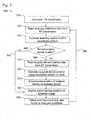
- Figure 3is a flow diagram for the tracking of a medical device used in an invasive procedure 300, according to an embodiment of the present invention.
- the LPS coordinate system of the operating roomis calibrated.
- RF data for calibrating the anatomyis read. This RF data for calibrating the anatomy is transmitted by RF transmitters which can be attached to anatomical structures in known locations.
- the anatomy relative to the LPS coordinate systemis calibrated.
- the useris asked whether the location of the surgical device should be reread. If the user chooses yes 346, then the surgical device location data transmitted from the RF transmitters on the surgical device is read in at step 350, and the position of the surgical device is calculated using the coordinate system of the room at step 360. Next, the location of the surgical device is superimposed on an image of the subject's anatomy at step 370, which is displayed to the user at step 380.
- step 340the user chooses not to update the location of the surgical device by answering no 342, then the display simply shows the last calculated image at step 380. If there was no previous image, then the display does not show anything.
- step 380is detecting and responding to any user inputs or changed conditions at step 390.
- the usermay want to change the anatomical area shown on the screen.
- the systemloops back to step 320 through return loop 395.
- step 390includes detecting and responding to any user inputs or changed conditions relating to any use of the machine.
- the systemcould detect a user request to increase RF energy in the beveled tip (see Fig. 4 ).
- step 390includes a user-controlled option to change the RF energy in the tip of the surgical device from a level that is useful for tracking the position of the surgical device to a level for improving navigation of surgical device during insertion into the body.
- the systemautomatically continuously updates the location of the surgical device without any affirmative user input to do so.
- the continuous dynamic feedback of the precise position of surgical instruments and/or medical apparatuses relative to the subject's anatomyallows dynamic correction for any deviation along the navigational path and/or any motion of the subject's body.
- An alternative embodiment of the inventionincludes a step that tracks and logs surgical instruments during surgical procedures, which improves the safety of surgical procedures.
- the Local Positioning System (LPS)in conjunction with the RF identifiers on surgical instruments allows the process of tracking and recording the RF identifiers to be fully automatic.
- the instrumentationwill be tracked both by its position and its identity during the course of the surgical procedure. This allows medical staff to precisely reach a targeted position within the body, which improves the safety of surgical procedures and expands the use of minimally invasive surgery. Logging the RF identifiers will also help prevent instrumentation from being left inside the subject after the surgical procedure has been completed.
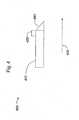
- FIG. 4is a schematic diagram of a detailed view of a surgical device for insertion into the body 400, according to an embodiment of the invention.
- Surgical device 400includes an injecting needle 410, which is for insertion into a body.
- Injecting needle 410includes beveled tip 440 and electrode 420.
- Electrode 420can be either attached or embedded to injecting needle 410.
- Insertion direction 450illustrates which direction injection needle 410 is injected into the body.
- Electrode 420can either be a monopolar electrode (with a neutral electrode somewhere on the subject through which the energy dissipates) or one of two bipolar electrodes. If electrode 420 is a monopolar electrode, the beveled tip 440 would need to be made of metal and the rest of injecting needle 410 made of some insulating material to prevent the return of energy down the needle shaft. If electrode 420 is a bipolar electrode, beveled tip 440 would act as one electrode and the shaft of injecting needle 410 (or a portion of the shaft) as the other electrode. Injecting needle 410 and beveled tip 440 could be coaxial.
- beveled tip 440is energized by RF energy in electrode 420. Energizing beveled tip 440 allows easier penetration and reduces the amount of lateral deflection caused by the beveled tip.
- the appropriate amount of energy (magnitude and waveform) needed to be applied to the beveled tip 440is enough to allow the injecting needle 410 to penetrate easily through tissues but not destroy excessive amounts of tissue. Corrections and adjustments in energy level and waveform will be accomplished by a manual adjustment of the controller or automated based on sensing applied force, needle deflection and/or numerical modeling of tissue. Selectively activating the RF energy can be used to navigate the slender medical instrument through variations in tissues using manual or automated systems.
- One reference for selecting the appropriate energy levelis the Ellman website disclosed above.
- beveled tip 440is energized to a level that is used for tracking injecting needle 410 as disclosed in Fig. 1 .
- the switch between a level that is used for tracking injecting needle 410 and any other useful level of RF energycan be either user-initiated, automatic, or a combination of both.
- the bevelit may be desirable to use the bevel to the user's advantage. That is, since it is known that the bevel will force the beveled tip 440 laterally in a certain direction, and since it is known that energizing the tip will reduce the magnitude of the lateral deflection, these attributes can be used to steer the needle tip. By manually dialing up or down the amount of energy or automating the amount of energy in beveled tip 440, the user can control the tip to deflect by a range of possible amounts for sharp or gradual turns. Furthermore, the direction of the bevel could change easily by simply rotating the entire injecting needle 410, assuming the needle is sheathed loosely enough that it can rotate within the sheath.
- the tip of a solid guide wire(not shown) is energized as opposed to using the bevel to achieve a controlled curved path.
- the guide wirewould have a sharp conical tip instead of a flat beveled tip.
- a cannulacould be slipped over the wire.
- the sheath(cannula) could already be around the wire and then the wire would be extracted, leaving the cannula in place, after inserting the device to the desired location.
- the userOnce the wire is out of the sheath, the user has the same final result of a tube through which injection or biopsy can be performed. This type of device without an energized tip is already commonly used clinically.
- Trajectories of curved pathsare important not only for the application described using a nitinol needle, but also in a new application not to our knowledge previously described: in the use of permanently-bent (non-shape-memory alloy) needles for biopsy or injection.
- a permanently bent needle or guide wireis curved along its entire path and its insertion is controlled by a device that feeds the needle out of a curved casing in a specific trajectory and location (possibly via a surgical robot).
- the pre-bent curved needlescould be available in a variety of user-defined radii and with the development of software the curved path of the needle could be planned.
- An energized pre-bent curved needleallows for a predictable path through various tissues knowing the radius, insertion point, and insertion trajectory.
- such a systemallows the surgeon to plan on a medical image of the desired tip location, entry point, and curved path and then to manually or automatically insert a needle according to this plan.
- numerical modeling of tissue penetrationmay be necessary to overcome the deviation of the needle path relative to the path expected through air. Selectively activating the RF energy at the tip of a needle or wire tip using a numerical model controls its penetration into the tissue and improves the accuracy of such a plan.
- the radio frequency signal emitted by the tip of the needle or guide wirecould be used for different purposes depending on the stage of the procedure. For example, low cutting energy without hemostasis could be applied during entry through the skin and superficial layers. After passing through these tissues, energy could be altered to cause hemostasis while the needle or wire passes through tissue that is sensitive to bleeding, such as the liver. Then, cutting energy could be increased further to pass through bone and cartilage. Further, if the terminal destination is a tumor, the tip could be highly energized to ablate the tumor. Note that this example uses several different waveforms/energy levels of the tip. Finally, the energy at the tip can be used for RF tracking as disclosed in Figs. 1-3 .
- One exemplary embodiment of the present inventionis a navigation system for invasive medical procedures.
- This navigation systemincludes a medical instrument that may be mounted on an end of arm tool and that is adapted to be inserted into a human body.
- a radio frequency (RF) transmitteris affixed to a distal end of the medical instrument.
- the systemalso includes a plurality of RF receivers that are adapted to receive RF signals emitted from the RF transmitter, as well as a computational device that is adapted to be operatively coupled to the plurality of RF receivers.
- the computational deviceis adapted to cause a visual image of a desired portion of a human body to be shown on a display and to overlay on the visual image an indication of the location of the medical instrument within the human body based on analysis of the information received from the RF receivers.
- a controllerthat is operatively coupled to the computational device and the end of arm tool is used to cause the end of arm tool to move the medical instrument to desired locations within a human body.
- the medical instrumentcomprises a needle or has a beveled leading edge.
- the RF transmittercan be located on the distal end of the medical instrument so that RF energy can be emitted therefrom which produces a force that balances the mechanical displacement force created by the beveled edge of the medical instrument.
- Three or more RF receiverscan be used.
- the computational deviceis adapted to receive information from the RF receivers in an iterative fashion.
- the computational deviceis adapted to receive information from the RF receiver in a dynamic fashion.
- the computational deviceis adapted to allow a user to pick a desired location within a human body and to dynamically provide information to the controller to cause it to move the end of arm tool and medical instrument to the desired location.
- the computation devicecomprises a personal computer.
- the RF transmittercan be located at a leading edge of the medical instrument.
- the RF transmitteris operatively coupled to the computational device, the computational device causing the RF transmitter to emit RF signals at desired times.
- two or more RF transmitterscan be affixed to the medical instrument at certain locations thereof, the two or more RF transmitters being selectively energizable to generate forces that are applied to the medical instrument and cause at least a portion of it to move in a desired direction.
- at least three RF transmitterscan be affixed to the medical instrument at desired locations thereof, if desired, the three RF transmitters being selectively energizable to generate forces that are applied to the medical instrument cause at least a portion of it to move in a desired direction.
- the three RF transmitterscan be evenly radially distributed around the medical instrument, at a distal end of the medical instrument and/or on a leading edge of the medical instrument.
Landscapes
- Health & Medical Sciences (AREA)
- Life Sciences & Earth Sciences (AREA)
- Surgery (AREA)
- Engineering & Computer Science (AREA)
- Molecular Biology (AREA)
- Animal Behavior & Ethology (AREA)
- Veterinary Medicine (AREA)
- Biomedical Technology (AREA)
- Heart & Thoracic Surgery (AREA)
- Medical Informatics (AREA)
- Public Health (AREA)
- General Health & Medical Sciences (AREA)
- Nuclear Medicine, Radiotherapy & Molecular Imaging (AREA)
- Pathology (AREA)
- Oral & Maxillofacial Surgery (AREA)
- Robotics (AREA)
- Human Computer Interaction (AREA)
- Physics & Mathematics (AREA)
- Biophysics (AREA)
- Surgical Instruments (AREA)
Description
- The present invention generally relates to improvements in the field of medical devices that use radio frequency (RF) signals. More particularly, the present invention concerns a medical device used in invasive procedures that uses RF signals for multiple applications, such as tracking an invasive instrument and improving the navigation of slender instruments during insertion and progression in the body.
- Various issued patents disclose using electromagnetic waves with medical devices. For example,
U.S. Patent No. 5,377,678, issued on January 3, 1995 , discloses a tracking system to follow the position and orientation of a device with RF fields. In the abstract of this patent, it is stated that the system disclosed in the patent involves radio frequency signals emitted by an invasive device such as a catheter. The abstract also states that the invasive device has a transmit coil attached near its end and is driven by a low power RF source to produce a dipole electromagnetic field that can be detected by an array of receive coils distributed around a region of interest. The abstract further discloses that the position and orientation of the device, as determined by the tracking system, are superimposed upon independently acquired Medical Diagnostic images, thereby minimizing the radiographic exposure times. - As another example,
U.S. Patent No. 5,445,150, and issued on August 29, 1995 , discloses an invasive system employing a radio frequency tracking system. In the abstract of this patent, it is stated that the system disclosed in the patent involves an invasive imaging system that employs a self-contained RF transmitter attached to an invasive device within a subject without physical connections to a tracking/display system and without the use of ionizing rays. The abstract further states that the radiated RF signal is received by receive coils of a tracking/display means, which calculates the location of the RF transmitter. The tracking/display means displays the medical diagnostic image on a monitor and superimposes a symbol on the image at a position corresponding to the calculated location of the RF transmitter. - Another example is
U.S. Patent No. 6,377,839, which issued on April 23, 2002 , and which discloses a tool guide for a surgical tool. In the abstract of this patent, it is stated that "[a] subject is secured to a subject support (10). A stereotaxic wand (40) is inserted into a tool guide (60)." The abstract also states that the wand has two emitters which selectively emit wand signals which are received by three receivers, and that a trajectory and location of the wand are superimposed on a diagnostic image on a monitor. If the surgeon is satisfied with the entry point and trajectory shown on the monitor, a surgical tool is inserted into the bore while the tool guide is held along the designated trajectory and at the designated entry point. - A still further example is
U.S. Patent No. 6,701,176, which issued on March 2, 2004 , and which is entitled "magnetic-resonance-guided imaging, electrophysiology, and ablation". In the abstract of this patent, it is stated that the system, in its preferred embodiment, provides an invasive combined electrophysiology and imaging antenna catheter, which includes an RF antenna for receiving magnetic resonance signals and diagnostic electrodes for receiving electrical potentials. The combined electrophysiology and imaging antenna catheter are used in combination with a magnetic resonance imaging scanner to guide and provide visualization during electrophysiologic diagnostic or therapeutic procedures. - A further example is
U.S. Patent No. 6,738,656, which issued on May 18, 2004 , and is entitled "Automatic Registration System for use with Position Tracking an Imaging System for use in Medical Applications." The abstract of this patent states it is a method of automatic registration which includes forming an image of a body part including a representation of markers fixed in a known position in space relative to a reference mount, positioning a sensing unit in a known position in space relative to the reference mount, and automatically registering the sensing unit in a space relative to the formed image based on the location of the markers in the formed image, the known location of the markers relative to the reference mount, and the known location of the sensing unit relative to the reference mount. - A further example is
U.S. Patent No. 6,833,814, which issued on December 21, 2004 , and is entitled "Intrabody Navigation System for Medical Applications." The abstract of this invention states it is a system and method for tracking the position and orientation of a probe such as a catheter whose transverse inner dimension may be at most about two millimeters. The abstract further states that three planar antennas that at least partly overlap are used to transmit electromagnetic radiation simultaneously, with the radiation transmitted by each antenna having its own spectrum. - A further example is
U.S. Patent No. 6,251,110, which issued on June 26, 2001 , and is entitled "Combined Radio Frequency And Ultrasonic Surgical Device". The abstract of this invention states that it is an energy-based surgical device for the application of ultrasonic energy and Radio Frequency energy. The abstract further states that the surgical device has a housing and an acoustic assembly having an electrically conductive waveguide, and the distal end of the waveguide of the acoustic assembly has an end effector for the conduction of ultrasonic energy or Radio Frequency energy. - A further example is
U.S. Patent No. 4,931,047, which issued on June 5, 1990 , and is entitled "Method And Apparatus For Providing Enhanced Tissue Fragmentation And/Or Hemostasis". The abstract of this invention states that it is an apparatus having a vibratable tip for ultrasonically disintegrating tissue in a surgical procedure and for aspirating the disintegrated tissue and fluids away from the surgical site through an opening in the tip. The abstract further discloses that a connection to an electrosurgical unit provides for delivery of RF cutting current, RF coagulating current, or a blend thereof, to the tip so that electrosurgical procedures can be conducted separately or simultaneously with ultrasonic aspiration through the tip. - A further example is European Patent Application
EP1504713A in which a computational device images a medical instrument within a human body. The medical instrument has a RF transmitter that is detected by RF receivers associated with the computational device. - There are a number of other patents that disclose tracking devices. For example,
U.S. Patent No. 7,015,859 , entitled "Electromagnetic Tracking System and Method Using a Three-Coil Wireless Transmitter" andU.S. Patent No. 6,285,902 , entitled "Computer Assisted Targeting Device for Use in Orthopaedic Surgery".U.S. Patent No. 6,628,894 discloses a hand held camera with tomographic capability. The tomographic imaging system disclosed in the patent includes a moveable detector or detectors capable of detecting gamma radiation, one or more position sensors for determining the position and angulation of the detector(s) in relation to a gamma ray emitting source, and a computational device for integrating the position and angulation of the detector(s) with information as to the energy and distribution of gamma rays detected by the detector and deriving a three dimensional representation of the source based on the integration. - Minimally invasive surgical procedures are being increasingly used to deposit or extract fluids, solid materials, or miniature devices internal to the body. Probes are being used that incorporate different devices including miniature cameras or that can apply different energy forms such as radio frequency (RF) energy to treat tissue. These types of applications require that a slender medical instrument reach a small target position internal to the body of the subject and that the position of the critical part of the medical instrument is always known through medical imaging, such as fluoroscopy.
- In many cases, a user needs to insert a long flexible needle (straight or curved) through the skin and deep into soft tissues for biopsy, injection, or insertion of a smaller diameter needle or wire through the needle's cannula. The path of the needle is not necessarily straight for two main reasons. The first reason that the needle's trajectory curves is that the tip of the needle is commonly beveled to make it sharp. The user inserts the needle by pushing it along its axis and the soft tissues encountered during insertion apply a component of reaction force perpendicular to the plane of the bevel. Therefore, the tip of the needle is forced to move away from the plane of the bevel.
- A second reason for the needle path varying unpredictably is that tissues of different density are encountered during insertion. The needle, in general, prefers to take the path of least resistance into the tissues that are easiest to penetrate. This path may not be the desired path.
- Currently, users often use beveled curved needles to reach pathology that is unreachable by a straight path. These curved needles are usually flexible and are made of shape memory alloy (e.g., nitinol) so that they can be fed through a long, straight rigid outer shaft. They then start to bend as they exit the shaft. For example, the straight outer shaft is first inserted to a desired linear depth to one side of a critical structure with the inner shape-memory curved needle pushed out to start a curved path (tracked by fluoroscopy) around the critical structure. To steer the needle, the user changes the radius of curvature by changing the amount of needle in or out of the straight shaft and the user changes the direction of the curved path by rotating the inner curved needle within the outer straight shaft. Such a procedure requires dexterity and constant fluoroscopic imaging to ensure the proper needle path.
- In addition to problems with predicting the path of the needle, it sometimes becomes difficult for the user to continue to advance the needle farther after a substantial portion of the needle is within the soft tissues. This problem occurs because the force to continue to insert the needle is the sum of the force to slice through new tissue plus the frictional resistance along the shaft of the needle that is within the tissue. As the needle is inserted farther and farther, this frictional resistance increases in direct proportion to the length of the shaft within the tissue.
- Therefore, it would be desirable for the user to be able to insert a needle with better predictability of its path and with less resistance to insertion.
- Radio frequency scalpels are produced by various companies (e.g., Ellman International, Oceanside, NY; Meyer-Haake, Wehrheim, Germany). These scalpels have advantages over standard scalpels in that they require less force to cut tissue and the tissues do not bleed much after cutting because the small blood vessels become cauterized by the radio frequency energy. However, there exists a need for radio frequency technology to be applied to a needle tip for easier penetration with less sideways deflection to ease navigation.
- A common reference for selecting the appropriate energy waveforms for certain types of procedures is described in the table on the Ellman website (http://www.ellman.com/surgitron/?MAIN=MEDICAL). The physician should be able to choose the level of energy based on whether hemostasis is desired and what types of tissues are being encountered. For example, when penetrating skin and superficial muscle, a low energy would be used, but if bone or other dense tissue were encountered, the energy could be increased.
- Heretofore, the positions of surgical instruments and/or apparatuses being used during minimally invasive surgical procedures have often been tracked by taking multiple x-ray images (fluoroscopy). This method of tracking position adds time to surgical procedures, provides only discrete steps of position change, and increases the exposure to radiation energy to the subject and medical staff.
- Present technology that is useful in some aspects of minimally invasive surgery is a guidance system that assists in locating the initial position of the surgical instrument and/or apparatus while it is external to the subject's body and can track rigid extensions of the instrument/apparatus that penetrate into the body. These existing guidance systems use direct line of sight and triangulation to calculate position by using two or more cameras in direct line of sight of each light source. The light sources are permanently attached to the instrument/apparatus (such as a wand) that is manually held in a spatial position relative to the subject. The position of the wand is calculated and imposed upon the diagnostic image. For tracking penetration into the subject of any kind of flexible device or of a rigid device that must penetrate deeper than the wand can allow, the position of the surgical instrument is tracked by taking multiple x-ray images. Of note, the movement of the outer surface of the subject is insufficient to account for movement of internal structures and organs. Complex internal movement can be caused by respiratory motion as well as a shift in the anatomic architecture occurring during some operative procedures (particularly partial debulking of tumor or other masses).
- There are many different surgical procedures that require surgical instruments to enter the body. Many applications require that the surgery be performed using minimally invasive surgical procedures, thereby creating the minimum disturbance and damage to the tissue of the body. By using minimally invasive techniques, the risk of infection is reduced and the recovery time is shorter.
- During minimally invasive surgical procedures, trying to determine the position of a surgical instrument that is internal to the body of the subject and to track the instrument's path relative to a navigation plan and to efficiently arrive at the planned target is quite cumbersome using existing technology. The efficient navigation of the surgical instrument and feedback of its precise position are critical to reducing the time and improving the quality of surgical procedures.
- Therefore, there exists a need for an improvement on existing technology that tracks the precise position of a surgical device.
- The invention is set forth in the appended claims, to which reference should now be made.
- In one embodiment, RF technology is used for multiple applications in medical devices. The embodiment provides, for example, a needle, probe, scalpel or any slender medical instrument with the RF energy at the leading edge of the instrument to reduce the mechanical forces created during penetration of tissue and/or to improve navigation of these instruments within the body in order to lessen or prevent the problems described above. This improves patient and medical staff safety and reduces the time of biopsy or minimally invasive surgical procedures. It should be noted that the RF signal emitted by the tip of the needle or guide wire can be used for different purposes depending on the stage of the procedure.
- In certain embodiments, RF transmissions are used to provide dynamic feedback to track the precise three-dimensional position of surgical instruments and/or medical apparatuses being used during biopsy and minimally invasive surgical procedures. This includes dynamically tracking the surgical instrument and/or medical apparatus, overlaying its position on a diagnostic image, correcting for any deviations to the navigation path and/or correcting dynamically for any movement of the subject's body.
- In one embodiment of the invention, an electrode capable of emitting RF energy is located at the tip of an invasive device. The RF energy at the tip of the device provides less resistance to insertion and reduces mechanical forces created during penetration of tissue, reducing or eliminating multiple x-ray exposures presently required to reach the target position when using biopsy needles, probes or slender medical instruments during minimally invasive surgery. Further, the RF energy reduces the need for the bevel on the tip of the needle, which is desired because a bevel creates deflecting mechanical side forces as the needle is penetrating the tissue making it difficult to reach the desired target. The RF energy is also used to correct the trajectory path of a curved biopsy needle by reducing deviation from its planned path and allowing for changing the linear and rotational relationship of the needle to the tube and angular position of the tube. As a result, accuracy and efficiency of reaching a targeted position during minimally invasive surgery is improved.
- In certain embodiments, selective activation of the RF energy at the tip of an invasive device is used to navigate the slender medical instrument through variations in tissues using manual or automated systems.
- Certain embodiments allow the clinician to create a controlled and accurate path from the surface of the body to the desired destination. This path can be curved, meaning that approaches that are not presently possible by a direct linear path will become possible. Examples of disease treatment using a curved path are: intervertebral disc extrusion from a contralateral posterior approach, biopsy or injection using curved path to avoid critical structures, and increased field of view during brain tumor resection through small craniotomy.
- In an embodiment of the invention, a RF transmitter on the surgical instrument also emits RF signals that allows the tracking of the location of the surgical instrument.
- In an embodiment, the invention provides a system for dynamically tracking three-dimensional position of surgical instruments, medical apparatuses and/or medical robotic devices being used during minimally invasive surgery. Further, certain embodiments of the invention provide a system for precisely following a navigation path using surgical planning tools and medical images by providing the actual position of the surgical instrument and allowing the medical staff, medical robotic system (e.g., a medical instrument mounted on an end of arm tool) or medical apparatuses to make on-going corrections to continue along the navigation path. The navigation can be pre-planned and/or dynamically adjusted as the procedure takes place, in order to precisely reach a targeted position within the body during minimally invasive surgical procedures.
- Certain embodiments of the invention also provide a system, method and means of tracking the position of surgical instruments, medical apparatuses and or medical robotic system during surgical procedures and to continuously overlay this geometric position data onto the diagnostic images of the patient. Certain embodiments of the invention provide for increasing the positional accuracy of surgical instruments, medical apparatus and/or medical robotic system as they are used in minimally invasive surgical procedures.
- In another embodiment, the invention provides a radio frequency (RF) identity to each surgical instrument so that a log of usage can be automatically recorded.
- In another embodiment, the invention provides a system where multiple probes can be inserted in internal soft tissues and then tracked in real-time to display the real-time deformation of the soft tissues.
- Some of the benefits of certain embodiments of the present invention include reducing the time and improving safety for minimally invasive surgical procedures, efficiently implanting devices, and expanding the use of minimally invasive surgical procedures. Other benefits include reducing the forces required in penetrating tissue with slender instruments and providing more predictability of movement with less resistance to insertion of slender instruments.
- Various examples objects, features and attendant advantages of the present invention will become fully appreciated as the same becomes better understood when considered in conjunction with the accompanying drawings, in which like reference characters designate the same or similar parts throughout the several views, and wherein:
Figure 1 is a schematic diagram of a medical device utilizing radiofrequency signals to dynamically determine the location of said medical device throughout the procedure, and also utilizing RF energy to improve navigation of said medical device.Figure 2 is a schematic diagram of a subsystem that dynamically calculates the position of a surgical instrument and superimposes said position on an image of the subject.Figure 3 is a flow diagram for the tracking of a medical device used in an invasive procedure.Figure 4 is a schematic diagram of a detailed view of a surgical device for insertion into the body.- While the present invention is susceptible of embodiment in various forms, there is shown in the drawings and will hereinafter be described a presently preferred embodiment with the understanding that the present disclosure is to be considered an exemplification of the invention and is not intended to limit the invention to the specific embodiment illustrated. It should be further understood that the title of this section of this specification, namely, "Detailed Description Of The Preferred Embodiments", relates to a requirement of the United States Patent Office, and does not imply, nor should be inferred to limit the subject matter disclosed herein.
- In the present disclosure, the words "a" or "an" are to be taken to include both the singular and the plural. Conversely, any reference to plural items shall, where appropriate, include the singular.
- For the purpose of this description anOperating Room is any room in which surgical procedures are performed. The termsurgical instrument for the purposes of this invention relates to any instrument, medical apparatus or medical robotic system used during surgical procedures.
Figure 1 is a schematic diagram of a medical device utilizing radio frequency signals to dynamically determine the location of said medical device throughout the procedure, and also utilizing RF energy to improve navigation of said medical device, according to an embodiment of the invention. The system shown inFigure 1 includes Local Positioning System (LPS) 160,LPS calibration device 170 andsurgical instrument 150.Surgical instrument 150 includesRF transmitters 120, which transmitRF transmissions 140, andRF tip 110.RF transmitters 120 are embedded into the structure ofsurgical instrument 150. Alternatively,RF transmitters 120 are attached tosurgical instrument 150.RF tip 110 is attached to an end ofsurgical instrument 150.LPS 160 includes a plurality ofRF receivers 130. The LPS for the operating room can be created because theRF receivers 130 are located at known fixed positions in the operating room, theRF receivers 130 operate on the same clock signal, and also the precise location ofRF receivers 130 relative to each other are known.LPS calibration device 170 includescalibration RF transmitters 180.- In certain embodiments, the RF energy emitted by
RF tip 110 can be changed from a level useful for navigating through tissue to a level useful for tracking the position of theRF tip 110 in theLPS 160. This change in RF energy level can be automatic, occurring at defined temporal intervals, in reaction to sensed events, or it can be user-selected. - In operation of certain embodiments, the precise position of
surgical instrument 150 is tracked during surgery using theRF transmissions 140 transmitted byRF transmitters 120 andRF tip 110.LPS 160 uses triangulation ofRF transmissions 140 to determine the position. Alternatively, only asingle RF transmitter 120 and/orRF tip 110 is attached tosurgical instrument 150. LPS calibration device 170 establishes and calibrates the positions of each of theRF receivers 130 relative to each other. TheLPS calibration device 170 incorporates a multiple ofcalibration RF transmitters 180 that are positioned at known locations on theLPS calibration device 170 and that are capable of transmitting a range of frequencies and identification signals.- Alternative to a
LPS calibration device 170, a precision positioning system (not shown) is used. The precision positioning system incorporates a signal or a multiple of RF transmitters capable of transmitting a range of frequencies and identification signals. Either method will use three transmitted signals to account for known points on a rigid structure to be tracked in three dimensions. AllRF receivers 130 in the operating room receive the signals from the transmitters on theLPS calibration device 170 or precision positioning system where the unique relative positions of theRF receivers 130 can be calculated by triangulation. - In operation,
surgical instrument 150 havingmultiple RF transmitters 120 imbedded into its structure will transmit signals to theRF receivers 130 in the operating room. Alternatively,surgical instrument 150 only has a single transmitter,RF tip 110 orRF transmitter 120. A single transmitter will allow the position of a key point onsurgical instrument 150 to be tracked (e. g., the tip or center of mass). Two transmitters, forinstance RF tip 110 and oneRF transmitter 120, will allow the position and orientation of a vector to be tracked (e.g., tip and shaft orientation of a straight guide tube). Three or more transmitters will allow all points on the rigid body ofsurgical instrument 150 to be tracked in three dimensions (e.g., a surgical plate that is being inserted).RF transmitters 120 andRF tip 110 are imbedded in the instrument in known positions relative tosurgical instrument 150's geometry. Previously recorded and stored dimensional data can be used to overlay images ofsurgical instrument 150 on the points whose positions are being tracked. - A battery or any other power source (not shown) can power the
RF transmitters 120 and/orRF tip 110; each has a unique identity and is capable of transmitting (if required) at different frequencies. In someembodiments RF tip 110 is capable of transmitting at frequencies useful for improving the navigation of slender instruments during insertion into the body. - To track
surgical instrument 150, the RF signals 140 are detected by each of theRF receivers 130 positioned in the operating room. Using triangulation calculations, the unique position of eitherRF transmitters 120 orRF tip 110 in the coordinate system of the operating room can be determined. This position and the position ofsurgical instrument 150 can then be overlaid on a representation (e.g. medical image) of the anatomy through a calibration process, which relates the coordinate location of the anatomy in the medical image to the coordinate location of the instrument in the operating room (seeFig. 2 ). - In an embodiment of the invention, RF transmitters (not shown) can be attached to anatomical structures (e.g., glued to skin, inserted via a needle into soft tissue) in known locations to calibrate the anatomy of a subject (not shown) relative to the coordinate system of the operating room.
- To track
surgical instrument 150, the RF signals 140 travel at a predictable velocity through air, and thus the position ofRF transmitters 120 andRF tip 110 can be calculated with greatest accuracy before the instrument enters the subject. After thesurgical instrument 150 enters the subject, the RF signal's 140 velocity may be altered due to the density of the tissue through which it travels. Accuracy of the detected transmitter position may be altered in this case if the signal experiences a delay as it travels through different tissues. Corrections and adjustments to the triangulation signals and calculations will be made based on the density of the tissues being penetrated and the approximate distance of the instrument within the tissues (based on depth and angle of instrument penetration). - In an embodiment of the present invention, RF energy in
RF tip 110 is changed (if necessary) to a level for improving navigation ofsurgical device 150 during insertion into the body. This improvement in navigation is further explained inFig. 4 . - In an embodiment of the present invention, multiple flexible probes with RF tips are inserted into soft tissues in the body used for real-time tracking of soft tissue displacement during the insertion of an instrument. The user will insert these thin probes in the region of interest near deforming internal tissues and organs. Each probe will have a RF tip with unique identifier. The subject will then receive a CT or MRI scan after probes are inserted. Then, since the positions of the tips can be visualized on the CT or MRI scans relative to the organs and soft tissues, the exact location of the tips relative to the internal structures can be defined. Since the tip location may be tracked in real-time, the movement of internal structures in response to breathing or pressure (such as the pressure of instruments performing a procedure nearby) can be tracked in real-time.
- The internal tracking information from multiple flexible probes with RF tips will be used to precisely locate the inserted instrument as it travels through moving tissue. If a tracking tip is attached to an instrument such as a flexible catheter, the position of the instrument tip is known relative to each of the thin probes, and therefore the position of the instrument tip is known relative to the moving organs and soft tissues. Computerized display can make use of known tissue deformation mechanics to portray a real-time representation of the deforming tissues (based on their original appearance from the CT or MRI) on a monitor for the user. The more probes that are used, the better the accuracy of the intervention. At least three probes are needed for determining an accurate initial position (before any deformation) to synchronize with medical images.
Figure 2 is a schematic diagram of a subsystem that dynamically calculates the position of a surgical instrument and superimposes said position on an image of the subject 200, according to an embodiment of the present invention. Thesystem 200 includes a plurality ofRF receivers 130, acomputer 210, a means for acquiring an anatomical image of the subject 230, auser input 240, anLPS calibration device 170, and a display means 220. TheRF receivers 130 are in electronic communication withcomputer 210 byconnection 205. TheLPS calibration device 170 is in electronic communication withcomputer 210 byconnection 207. The means for acquiring an anatomical image of the subject 230 is also in electrical communication with thecomputer 210 byconnection 215. The user may make adjustments to the system throughuser inputs 240, which are detected bycomputer 210. The computer is in electric communication with the display means 220 throughconnection 225.- In operation,
computer 210 receives LPS calibration data fromLPS calibration device 170 throughconnection 207. This enablescomputer 210 to create the LPS coordinate system of the operating room. - Then,
computer 210 needs to calibrate the anatomy relative to the coordinate system of the operating room.RF receivers 130 receive RF signals from RF transmitters attached to anatomical structures (not shown). TheRF receivers 130 communicate said received RF signal tocomputer 210 throughconnection 205.Computer 210 then uses this information to calibrate the anatomical position of the subject relative to the coordinate system of the room. Further, positions of these transmitters can then be tracked to account for subject movement (e.g., breathing) or organ movement (e.g., displacement of the organ away from a tool that is being inserted). The anatomical representation displayed on display means 220 can be shifted, scaled, or distorted as necessary to depict such movement. These adjustments to the anatomical representation can either be made automatically bycomputer 210, or be user-initiated throughuser input 240. Alternatively, if less accuracy is required and the subject is adequately restrained to prevent any movement, a wand tool with RF transmitters can be used to point to fixed locations that are henceforth assumed to remain fixed. - Next, the position of the medical instrument itself is tracked. RF signals emitted from the RF transmitters (see
Fig. 1 RF transmitter 120, RF tip 110) are received byRF receivers 130. TheRF receivers 130 communicate said received RF signal tocomputer 210 throughconnection 205. Sincecomputer 210 has calibrated the position of the anatomical representation and the position of each of theRF receivers 130 relative to each other (seeFig. 1 LPS 160), it is able to triangulate the precise position of the surgical instrument (seeFig 1 . instrument 150) and determine its position in relation to both the coordinate system of the room and the anatomical representation. - An anatomical representation is captured by a means for acquiring an anatomical image of the subject 230. In one embodiment of the present invention, the means for acquiring an anatomical image of the subject 230 is an x-ray. Alternatively, the means for acquiring an anatomical image of the subject 230 is a tomographic image. Other types of anatomical imaging methods also may be employed. The anatomical representation captured by the means for acquiring an
anatomical image 230 is communicated tocomputer 210 throughconnection 215. Computer 210 then superimposes the location of the medical instrument on the anatomical image sent by means foranatomical image 230. This superimposition is sent to display means 220 throughconnection 225, where it is displayed on display means 220. The user of the present invention can see precisely where surgical instrument (seeFig. 1 instrument 150) is located inside the body of the subject. According to an embodiment of the invention, the user of the present invention can makeuser inputs 240 in order to change options. For example, the user of the present invention may prefer to view a smaller portion of the anatomical image with the superimposed surgical device. The user of the present invention can input this preference throughuser input 240, and the display shown on display means 220 should react accordingly.- In another embodiment of the present invention,
computer 210 is connected to a controller which is used to control a robotic apparatus (e.g., an end of arm tool on which a medical instrument can be mounted). Any data received or computed bycomputer 210 is available to the controller for controlling a robotic apparatus, and any information known by the controller is available to thecomputer 210. The controller can use this information to control the robotic apparatus for uses such as conducting or assisting in medical procedures. In one embodiment, thecomputer 210 sends the controller the location of the desired point of insertion and the coordinates of the target end point for the surgical instrument.Computer 210 also sends the controller the desired path of insertion. The controller signals the robotic apparatus to insert the needle at the desired location, follow the desired path and reach the target point. Concurrently,computer 210 dynamically and continuously sends the controller the location of the surgical device, while the controller sendscomputer 210 the location of the robotic apparatus.Computer 210 can compare the two locations along with the desired navigation path. If there is a discrepancy between the desired navigation path and the location of the robotic apparatus, thencomputer 210 can communicate to the controller to make corrective adjustments to the position of the robotic apparatus. Figure 3 is a flow diagram for the tracking of a medical device used in aninvasive procedure 300, according to an embodiment of the present invention.- First, at
step 310, the LPS coordinate system of the operating room is calibrated. Next, atstep 320, RF data for calibrating the anatomy is read. This RF data for calibrating the anatomy is transmitted by RF transmitters which can be attached to anatomical structures in known locations. Next, atstep 330, the anatomy relative to the LPS coordinate system is calibrated. - At
step 340, the user is asked whether the location of the surgical device should be reread. If the user chooses yes 346, then the surgical device location data transmitted from the RF transmitters on the surgical device is read in atstep 350, and the position of the surgical device is calculated using the coordinate system of the room atstep 360. Next, the location of the surgical device is superimposed on an image of the subject's anatomy atstep 370, which is displayed to the user atstep 380. - If at
step 340 the user chooses not to update the location of the surgical device by answering no 342, then the display simply shows the last calculated image atstep 380. If there was no previous image, then the display does not show anything. - Regardless of whether
path step 390. For example, the user may want to change the anatomical area shown on the screen. Finally, the system loops back to step 320 throughreturn loop 395. - In an alternative embodiment,
step 390 includes detecting and responding to any user inputs or changed conditions relating to any use of the machine. For example, atstep 390 the system could detect a user request to increase RF energy in the beveled tip (seeFig. 4 ). - In an alternative embodiment,
step 390 includes a user-controlled option to change the RF energy in the tip of the surgical device from a level that is useful for tracking the position of the surgical device to a level for improving navigation of surgical device during insertion into the body. - In an alternative embodiment, the system automatically continuously updates the location of the surgical device without any affirmative user input to do so. The continuous dynamic feedback of the precise position of surgical instruments and/or medical apparatuses relative to the subject's anatomy allows dynamic correction for any deviation along the navigational path and/or any motion of the subject's body.
- Currently, to determine the position of a surgical instrument that is internal to the body of the subject, to track the instrument's path relative to a navigation plan, and to efficiently arrive at the planned target is quite cumbersome.
- An alternative embodiment of the invention includes a step that tracks and logs surgical instruments during surgical procedures, which improves the safety of surgical procedures. The Local Positioning System (LPS) in conjunction with the RF identifiers on surgical instruments allows the process of tracking and recording the RF identifiers to be fully automatic. The instrumentation will be tracked both by its position and its identity during the course of the surgical procedure. This allows medical staff to precisely reach a targeted position within the body, which improves the safety of surgical procedures and expands the use of minimally invasive surgery. Logging the RF identifiers will also help prevent instrumentation from being left inside the subject after the surgical procedure has been completed.
Figure 4 is a schematic diagram of a detailed view of a surgical device for insertion into thebody 400, according to an embodiment of the invention.Surgical device 400 includes an injectingneedle 410, which is for insertion into a body. Injectingneedle 410 includesbeveled tip 440 andelectrode 420.Electrode 420 can be either attached or embedded to injectingneedle 410.Insertion direction 450 illustrates whichdirection injection needle 410 is injected into the body.Electrode 420 can either be a monopolar electrode (with a neutral electrode somewhere on the subject through which the energy dissipates) or one of two bipolar electrodes. Ifelectrode 420 is a monopolar electrode, thebeveled tip 440 would need to be made of metal and the rest of injectingneedle 410 made of some insulating material to prevent the return of energy down the needle shaft. Ifelectrode 420 is a bipolar electrode,beveled tip 440 would act as one electrode and the shaft of injecting needle 410 (or a portion of the shaft) as the other electrode. Injectingneedle 410 andbeveled tip 440 could be coaxial.- During operation,
beveled tip 440 is energized by RF energy inelectrode 420. Energizingbeveled tip 440 allows easier penetration and reduces the amount of lateral deflection caused by the beveled tip. - The appropriate amount of energy (magnitude and waveform) needed to be applied to the
beveled tip 440 is enough to allow the injectingneedle 410 to penetrate easily through tissues but not destroy excessive amounts of tissue. Corrections and adjustments in energy level and waveform will be accomplished by a manual adjustment of the controller or automated based on sensing applied force, needle deflection and/or numerical modeling of tissue. Selectively activating the RF energy can be used to navigate the slender medical instrument through variations in tissues using manual or automated systems. One reference for selecting the appropriate energy level is the Ellman website disclosed above. - Alternatively,
beveled tip 440 is energized to a level that is used for tracking injectingneedle 410 as disclosed inFig. 1 . The switch between a level that is used for tracking injectingneedle 410 and any other useful level of RF energy can be either user-initiated, automatic, or a combination of both. - In some cases, it may be desirable to use the bevel to the user's advantage. That is, since it is known that the bevel will force the
beveled tip 440 laterally in a certain direction, and since it is known that energizing the tip will reduce the magnitude of the lateral deflection, these attributes can be used to steer the needle tip. By manually dialing up or down the amount of energy or automating the amount of energy inbeveled tip 440, the user can control the tip to deflect by a range of possible amounts for sharp or gradual turns. Furthermore, the direction of the bevel could change easily by simply rotating theentire injecting needle 410, assuming the needle is sheathed loosely enough that it can rotate within the sheath. - In an alternative embodiment, there could be two electrodes at the tip-one on the bevel side and one on the flat side. By selectively activating one of the electrodes, it would either create a sharper turn than without energization (straight side activated) or a less of a turn than without energization (bevel side activated). These two electrodes could both act as monopolar electrodes, or they could be switched to act as two parts of a bipolar electrode if the difficulty of steering is not an issue.
- In an alternative embodiment, the tip of a solid guide wire (not shown) is energized as opposed to using the bevel to achieve a controlled curved path. The guide wire would have a sharp conical tip instead of a flat beveled tip. After the guide wire is inserted to its destination (curved or straight path), a cannula could be slipped over the wire. Alternately, the sheath (cannula) could already be around the wire and then the wire would be extracted, leaving the cannula in place, after inserting the device to the desired location. Once the wire is out of the sheath, the user has the same final result of a tube through which injection or biopsy can be performed. This type of device without an energized tip is already commonly used clinically.
- Trajectories of curved paths are important not only for the application described using a nitinol needle, but also in a new application not to our knowledge previously described: in the use of permanently-bent (non-shape-memory alloy) needles for biopsy or injection. A permanently bent needle or guide wire is curved along its entire path and its insertion is controlled by a device that feeds the needle out of a curved casing in a specific trajectory and location (possibly via a surgical robot).
- The pre-bent curved needles could be available in a variety of user-defined radii and with the development of software the curved path of the needle could be planned. An energized pre-bent curved needle allows for a predictable path through various tissues knowing the radius, insertion point, and insertion trajectory. Thus, such a system allows the surgeon to plan on a medical image of the desired tip location, entry point, and curved path and then to manually or automatically insert a needle according to this plan. To account for deflection of the shaft, numerical modeling of tissue penetration may be necessary to overcome the deviation of the needle path relative to the path expected through air. Selectively activating the RF energy at the tip of a needle or wire tip using a numerical model controls its penetration into the tissue and improves the accuracy of such a plan.
- It should be noted that the radio frequency signal emitted by the tip of the needle or guide wire could be used for different purposes depending on the stage of the procedure. For example, low cutting energy without hemostasis could be applied during entry through the skin and superficial layers. After passing through these tissues, energy could be altered to cause hemostasis while the needle or wire passes through tissue that is sensitive to bleeding, such as the liver. Then, cutting energy could be increased further to pass through bone and cartilage. Further, if the terminal destination is a tumor, the tip could be highly energized to ablate the tumor. Note that this example uses several different waveforms/energy levels of the tip. Finally, the energy at the tip can be used for RF tracking as disclosed in
Figs. 1-3 . - One exemplary embodiment of the present invention is a navigation system for invasive medical procedures. This navigation system includes a medical instrument that may be mounted on an end of arm tool and that is adapted to be inserted into a human body. A radio frequency (RF) transmitter is affixed to a distal end of the medical instrument. The system also includes a plurality of RF receivers that are adapted to receive RF signals emitted from the RF transmitter, as well as a computational device that is adapted to be operatively coupled to the plurality of RF receivers. The computational device is adapted to cause a visual image of a desired portion of a human body to be shown on a display and to overlay on the visual image an indication of the location of the medical instrument within the human body based on analysis of the information received from the RF receivers. A controller that is operatively coupled to the computational device and the end of arm tool is used to cause the end of arm tool to move the medical instrument to desired locations within a human body.
- In one application, the medical instrument comprises a needle or has a beveled leading edge. The RF transmitter can be located on the distal end of the medical instrument so that RF energy can be emitted therefrom which produces a force that balances the mechanical displacement force created by the beveled edge of the medical instrument. Three or more RF receivers can be used.
- The computational device is adapted to receive information from the RF receivers in an iterative fashion. Alternatively, the computational device is adapted to receive information from the RF receiver in a dynamic fashion.
- In an exemplary embodiment, the computational device is adapted to allow a user to pick a desired location within a human body and to dynamically provide information to the controller to cause it to move the end of arm tool and medical instrument to the desired location. The computation device comprises a personal computer.
- The RF transmitter can be located at a leading edge of the medical instrument. The RF transmitter is operatively coupled to the computational device, the computational device causing the RF transmitter to emit RF signals at desired times.
- If desired, two or more RF transmitters can be affixed to the medical instrument at certain locations thereof, the two or more RF transmitters being selectively energizable to generate forces that are applied to the medical instrument and cause at least a portion of it to move in a desired direction. Similarly, at least three RF transmitters can be affixed to the medical instrument at desired locations thereof, if desired, the three RF transmitters being selectively energizable to generate forces that are applied to the medical instrument cause at least a portion of it to move in a desired direction. The three RF transmitters can be evenly radially distributed around the medical instrument, at a distal end of the medical instrument and/or on a leading edge of the medical instrument.
- With respect to the above description then, it is to be realized that the optimum dimensional relationships for the parts of the invention, to include variations in size, materials, shape, form, function and manner of operation, assembly and use, are deemed readily apparent and obvious to one skilled in the art, and all equivalent relationships to those illustrated in the drawings and described in the specification are intended to be encompassed by the present invention.
- Therefore, the foregoing is considered as illustrative only of the principles of the invention. Further, since numerous modifications and changes will readily occur to those skilled in the art, it is not desired to limit the invention to the exact construction and operation shown and described, and accordingly, all suitable modifications and equivalents may be resorted to, falling within the scope of the invention.
Claims (15)
- A navigation system (160) for invasive medical procedures, comprising:a medical instrument (150) adapted to be inserted into a human body along an axis of insertion;at least one radio frequency (RF) transmitter (110) affixed to a distal end of the medical instrument;a plurality of RF receivers (130) that are adapted to receive RF signals emitted from the RF transmitter; anda computational device (210) that is adapted to be operatively coupled to the plurality of RF receivers, the computational device being adapted to cause a visual image of a desired portion of a human body to be shown on a display (220) and to overlay on the visual image an indication of the location of the medical instrument within the human body based on analysis of the information received from the RF receivers;wherein the navigation system ischaracterised in that the at least one radio frequency (RF) transmitter (110) is capable of emitting energy sufficient to ablate abutting tissue, andin that the medical instrument comprises a bevelled leading edge (440) at the distal end,andin that the navigation system further comprises:an end of arm tool on which the medical instrument is mounted; anda controller that is operatively coupled to the computational device and the end of arm tool, the controller being configured to steer the medical instrument to desired locations within a human body by selectively activating the RF transmitter to emit energy in an amount sufficient to control the degree of deflection of the medical instrument lateral to the axis of insertion.
- The system of claim 1, wherein the medical instrument comprises a needle (410).
- The system of claim 1, wherein RF energy can be emitted from the RF transmitter which reduces a force needed to penetrate through tissue opposing the bevelled edge of the medical instrument.
- The system of claim 1 , wherein the plurality of RF receivers comprises three or more RF receivers.
- The system of claim 1, wherein the computational device is adapted to receive information from the RF receivers in an iterative fashion.
- The system of claim 1, wherein the computational device is adapted to receive information from the RF receiver in a dynamic fashion.
- The system of claim 1, wherein the computational device is adapted to allow a user to pick a desired location within a human body and to dynamically provide information to the controller to cause it to move the end of arm tool and medical instrument to the desired location.
- The system of claim 1, wherein the computation device comprises a personal computer.
- The system of claim 1 , wherein the RF transmitter is located at a leading edge of the medical instrument.
- The system of claim 1, wherein the RF transmitter is operatively coupled to the computational device, and wherein the computational device causes the RF transmitter to emit RF signals at desired times.
- The system of claim 1, wherein two or more RF transmitters are affixed to the medical instrument at desired locations thereof, the two or more RF transmitters being selectively energizable to generate forces that are applied to the medical instrument and cause at least a portion of it to move in a desired direction.
- The system of claim 1, wherein at least three RF transmitters are affixed to the medical instrument at desired locations thereof, the three RF transmitters being selectively energizable to generate forces that are applied to the medical instrument cause at least a portion of it to move in a desired direction.
- The system of claim 12, wherein the three RF transmitters are evenly radially distributed around the medical instrument.
- The system of claim 13, wherein the three RF transmitters are located at the distal end of the medical instrument.
- The system of claim 14, wherein at least one of the three RF transmitters is located on a leading edge of the medical instrument.
Applications Claiming Priority (3)
| Application Number | Priority Date | Filing Date | Title |
|---|---|---|---|
| US77458606P | 2006-02-16 | 2006-02-16 | |
| US77581606P | 2006-02-16 | 2006-02-16 | |
| PCT/US2007/062346WO2007095637A1 (en) | 2006-02-16 | 2007-02-16 | System utilizing radio frequency signals for tracking and improving navigation of slender instruments during insertion into the body |
Publications (2)
| Publication Number | Publication Date |
|---|---|
| EP1991121A1 EP1991121A1 (en) | 2008-11-19 |
| EP1991121B1true EP1991121B1 (en) | 2014-08-06 |
Family
ID=38137326
Family Applications (1)
| Application Number | Title | Priority Date | Filing Date |
|---|---|---|---|
| EP07757145.3AActiveEP1991121B1 (en) | 2006-02-16 | 2007-02-16 | System utilizing radio frequency signals for tracking and improving navigation of slender instruments during insertion into the body |
Country Status (4)
| Country | Link |
|---|---|
| US (1) | US8010181B2 (en) |
| EP (1) | EP1991121B1 (en) |
| CA (1) | CA2642481C (en) |
| WO (1) | WO2007095637A1 (en) |
Families Citing this family (103)
| Publication number | Priority date | Publication date | Assignee | Title |
|---|---|---|---|---|
| WO2007092054A2 (en) | 2006-02-06 | 2007-08-16 | Specht Donald F | Method and apparatus to visualize the coronary arteries using ultrasound |
| US8219178B2 (en)* | 2007-02-16 | 2012-07-10 | Catholic Healthcare West | Method and system for performing invasive medical procedures using a surgical robot |
| US8219177B2 (en)* | 2006-02-16 | 2012-07-10 | Catholic Healthcare West | Method and system for performing invasive medical procedures using a surgical robot |
| US10893912B2 (en)* | 2006-02-16 | 2021-01-19 | Globus Medical Inc. | Surgical tool systems and methods |
| US8560047B2 (en) | 2006-06-16 | 2013-10-15 | Board Of Regents Of The University Of Nebraska | Method and apparatus for computer aided surgery |
| WO2008051639A2 (en) | 2006-10-25 | 2008-05-02 | Maui Imaging, Inc. | Method and apparatus to produce ultrasonic images using multiple apertures |
| US20090209849A1 (en)* | 2007-05-02 | 2009-08-20 | Philip Stephen Rowe | Medical Device Placement and Monitoring System Utilizing Radio Frequency Identification |
| CN101801445B (en) | 2007-08-14 | 2013-04-17 | 弗雷德哈钦森癌症研究中心 | Needle Array Assembly for Delivery of Therapeutic Drugs |
| US10226234B2 (en) | 2011-12-01 | 2019-03-12 | Maui Imaging, Inc. | Motion detection using ping-based and multiple aperture doppler ultrasound |
| US9788813B2 (en) | 2010-10-13 | 2017-10-17 | Maui Imaging, Inc. | Multiple aperture probe internal apparatus and cable assemblies |
| US9282945B2 (en) | 2009-04-14 | 2016-03-15 | Maui Imaging, Inc. | Calibration of ultrasound probes |
| US20090085807A1 (en)* | 2007-10-02 | 2009-04-02 | General Electric Company | Coil array for an electromagnetic tracking system |
| KR101659723B1 (en) | 2009-04-14 | 2016-09-26 | 마우이 이미징, 인코포레이티드 | Multiple aperture ultrasound array alignment fixture |
| EP2578178A3 (en)* | 2009-04-28 | 2014-12-31 | Brainlab AG | Method for controlling software for supporting treatment |
| US10433917B2 (en)* | 2009-05-29 | 2019-10-08 | Jack Wade | System and method for enhanced data analysis with video enabled software tools for medical environments |
| US10517688B2 (en)* | 2009-05-29 | 2019-12-31 | Jack Wade | Method for enhanced data analysis with specialized video enabled software tools for medical environments |
| US20180289443A1 (en)* | 2009-05-29 | 2018-10-11 | Jack Wade | System and method for enhanced data analysis with specialized video enabled software tools for medical environments |
| US11744668B2 (en)* | 2009-05-29 | 2023-09-05 | Jack Wade | System and method for enhanced data analysis with specialized video enabled software tools for medical environments |
| US11896196B2 (en)* | 2009-05-29 | 2024-02-13 | Jack Wade | Method for enhanced data analysis with specialized video enabled software tools for medical environments |
| WO2010144402A2 (en) | 2009-06-08 | 2010-12-16 | Surgivision, Inc. | Mri-guided surgical systems with preset scan planes |
| CN102625670B (en) | 2009-06-16 | 2015-07-15 | 核磁共振成像介入技术有限公司 | MRI-guided devices and MRI-guided interventional systems that can track and generate dynamic visualizations of the devices in near real time |
| US8509874B2 (en)* | 2009-07-30 | 2013-08-13 | Beth Israel Deaconess Medical Center | Method for non-contrast enhanced pulmonary vein magnetic resonance imaging |
| US8319687B2 (en)* | 2009-12-09 | 2012-11-27 | Trimble Navigation Limited | System for determining position in a work space |
| JP6274724B2 (en) | 2010-02-18 | 2018-02-07 | マウイ イマギング,インコーポレーテッド | Point source transmission and sound velocity correction using multi-aperture ultrasound imaging |
| US9107684B2 (en)* | 2010-03-05 | 2015-08-18 | Covidien Lp | System and method for transferring power to intrabody instruments |
| FR2959409B1 (en) | 2010-05-03 | 2012-06-29 | Gen Electric | METHOD FOR DETERMINING A TOOL INSERTION PATH IN A DEFORMABLE TISSUE MATRIX AND ROBOTIC SYSTEM USING THE METHOD |
| KR101906838B1 (en) | 2010-10-13 | 2018-10-11 | 마우이 이미징, 인코포레이티드 | Concave ultrasound transducers and 3d arrays |
| WO2012059867A1 (en)* | 2010-11-05 | 2012-05-10 | Koninklijke Philips Electronics N.V. | Imaging apparatus for imaging an object |
| JP5959150B2 (en)* | 2011-01-12 | 2016-08-02 | オリンパス株式会社 | Endoscope system |
| JP5752945B2 (en)* | 2011-01-24 | 2015-07-22 | オリンパス株式会社 | Endoscope system |
| US9498231B2 (en) | 2011-06-27 | 2016-11-22 | Board Of Regents Of The University Of Nebraska | On-board tool tracking system and methods of computer assisted surgery |
| CN103764061B (en) | 2011-06-27 | 2017-03-08 | 内布拉斯加大学评议会 | On Tool Tracking System and Computer Assisted Surgery Method |
| US11911117B2 (en) | 2011-06-27 | 2024-02-27 | Board Of Regents Of The University Of Nebraska | On-board tool tracking system and methods of computer assisted surgery |
| SG10201508662SA (en) | 2011-10-28 | 2015-11-27 | Presage Biosciences Inc | Methods for drug delivery |
| JP2015503404A (en) | 2011-12-29 | 2015-02-02 | マウイ イマギング,インコーポレーテッド | Arbitrary path M-mode ultrasound imaging |
| JP6438769B2 (en) | 2012-02-21 | 2018-12-19 | マウイ イマギング,インコーポレーテッド | Determination of material hardness using multiple aperture ultrasound. |
| JP6104601B2 (en)* | 2012-03-06 | 2017-03-29 | 東芝メディカルシステムズ株式会社 | X-ray diagnostic imaging apparatus and control program |
| WO2013148673A1 (en) | 2012-03-26 | 2013-10-03 | Maui Imaging, Inc. | Systems and methods for improving ultrasound image quality by applying weighting factors |
| US10799298B2 (en) | 2012-06-21 | 2020-10-13 | Globus Medical Inc. | Robotic fluoroscopic navigation |
| US10758315B2 (en) | 2012-06-21 | 2020-09-01 | Globus Medical Inc. | Method and system for improving 2D-3D registration convergence |
| US11857149B2 (en) | 2012-06-21 | 2024-01-02 | Globus Medical, Inc. | Surgical robotic systems with target trajectory deviation monitoring and related methods |
| US11317971B2 (en) | 2012-06-21 | 2022-05-03 | Globus Medical, Inc. | Systems and methods related to robotic guidance in surgery |
| US10624710B2 (en) | 2012-06-21 | 2020-04-21 | Globus Medical, Inc. | System and method for measuring depth of instrumentation |
| US11589771B2 (en) | 2012-06-21 | 2023-02-28 | Globus Medical Inc. | Method for recording probe movement and determining an extent of matter removed |
| US11963755B2 (en) | 2012-06-21 | 2024-04-23 | Globus Medical Inc. | Apparatus for recording probe movement |
| US11864745B2 (en) | 2012-06-21 | 2024-01-09 | Globus Medical, Inc. | Surgical robotic system with retractor |
| US11864839B2 (en) | 2012-06-21 | 2024-01-09 | Globus Medical Inc. | Methods of adjusting a virtual implant and related surgical navigation systems |
| US10842461B2 (en) | 2012-06-21 | 2020-11-24 | Globus Medical, Inc. | Systems and methods of checking registrations for surgical systems |
| US10874466B2 (en) | 2012-06-21 | 2020-12-29 | Globus Medical, Inc. | System and method for surgical tool insertion using multiaxis force and moment feedback |
| US11896446B2 (en) | 2012-06-21 | 2024-02-13 | Globus Medical, Inc | Surgical robotic automation with tracking markers |
| US11253327B2 (en) | 2012-06-21 | 2022-02-22 | Globus Medical, Inc. | Systems and methods for automatically changing an end-effector on a surgical robot |
| US11399900B2 (en) | 2012-06-21 | 2022-08-02 | Globus Medical, Inc. | Robotic systems providing co-registration using natural fiducials and related methods |
| US11786324B2 (en) | 2012-06-21 | 2023-10-17 | Globus Medical, Inc. | Surgical robotic automation with tracking markers |
| US11857266B2 (en) | 2012-06-21 | 2024-01-02 | Globus Medical, Inc. | System for a surveillance marker in robotic-assisted surgery |
| US11298196B2 (en) | 2012-06-21 | 2022-04-12 | Globus Medical Inc. | Surgical robotic automation with tracking markers and controlled tool advancement |
| US12004905B2 (en) | 2012-06-21 | 2024-06-11 | Globus Medical, Inc. | Medical imaging systems using robotic actuators and related methods |
| US11793570B2 (en) | 2012-06-21 | 2023-10-24 | Globus Medical Inc. | Surgical robotic automation with tracking markers |
| US11974822B2 (en) | 2012-06-21 | 2024-05-07 | Globus Medical Inc. | Method for a surveillance marker in robotic-assisted surgery |
| US11045267B2 (en) | 2012-06-21 | 2021-06-29 | Globus Medical, Inc. | Surgical robotic automation with tracking markers |
| EP2863827B1 (en)* | 2012-06-21 | 2022-11-16 | Globus Medical, Inc. | Surgical robot platform |
| US20170258535A1 (en)* | 2012-06-21 | 2017-09-14 | Globus Medical, Inc. | Surgical robotic automation with tracking markers |
| DE102012107274A1 (en)* | 2012-08-08 | 2014-03-06 | Aesculap Ag | Apparatus and method for simultaneously identifying a plurality of surgical instruments |
| JP6270843B2 (en) | 2012-08-10 | 2018-01-31 | マウイ イマギング,インコーポレーテッド | Calibration of multiple aperture ultrasonic probes |
| WO2014031642A1 (en) | 2012-08-21 | 2014-02-27 | Maui Imaging, Inc. | Ultrasound imaging system memory architecture |
| US20140064513A1 (en) | 2012-09-06 | 2014-03-06 | MUSIC Group IP Ltd. | System and method for remotely controlling audio equipment |
| WO2014160291A1 (en) | 2013-03-13 | 2014-10-02 | Maui Imaging, Inc. | Alignment of ultrasound transducer arrays and multiple aperture probe assembly |
| CN105050527B (en) | 2013-03-15 | 2018-03-27 | 圣纳普医疗(巴巴多斯)公司 | Intelligent positioning system and method therefor |
| US10105149B2 (en) | 2013-03-15 | 2018-10-23 | Board Of Regents Of The University Of Nebraska | On-board tool tracking system and methods of computer assisted surgery |
| EP2967347B1 (en) | 2013-03-15 | 2023-09-06 | Synaptive Medical Inc. | Intramodal synchronization of surgical data |
| WO2014139019A1 (en) | 2013-03-15 | 2014-09-18 | Synaptive Medical (Barbados) Inc. | System and method for dynamic validation, correction of registration for surgical navigation |
| US10154826B2 (en) | 2013-07-17 | 2018-12-18 | Tissue Differentiation Intelligence, Llc | Device and method for identifying anatomical structures |
| US10716536B2 (en) | 2013-07-17 | 2020-07-21 | Tissue Differentiation Intelligence, Llc | Identifying anatomical structures |
| US9883848B2 (en) | 2013-09-13 | 2018-02-06 | Maui Imaging, Inc. | Ultrasound imaging using apparent point-source transmit transducer |
| US10595836B2 (en) | 2014-03-17 | 2020-03-24 | Intuitive Surgical Operations, Inc. | Systems and methods for confirming disc engagement |
| KR102395425B1 (en) | 2014-03-17 | 2022-05-09 | 인튜어티브 서지컬 오퍼레이션즈 인코포레이티드 | Alignment and engagement for teleoperated actuated surgical instruments |
| CN106794007B (en) | 2014-08-18 | 2021-03-09 | 毛伊图像公司 | Network-based ultrasound imaging system |
| US20160262654A1 (en)* | 2015-03-09 | 2016-09-15 | Steven R. Wedan | Tracking signals for catheter |
| US11367947B2 (en)* | 2015-03-16 | 2022-06-21 | St. Jude Medical International Holding S.á r.l. | Field concentrating antennas for magnetic position sensors |
| KR102681141B1 (en) | 2015-03-30 | 2024-07-02 | 마우이 이미징, 인코포레이티드 | Ultrasonic imaging systems and methods for detecting object motion |
| US20190000575A1 (en)* | 2015-12-29 | 2019-01-03 | Koninklijke Philips N.V. | Image guided robotic convergent ablation |
| WO2017115235A1 (en)* | 2015-12-29 | 2017-07-06 | Koninklijke Philips N.V. | Image-based adaptive path planning for a robot |
| CN108778530B (en) | 2016-01-27 | 2021-07-27 | 毛伊图像公司 | Ultrasound imaging with sparse array detectors |
| US11883217B2 (en) | 2016-02-03 | 2024-01-30 | Globus Medical, Inc. | Portable medical imaging system and method |
| EP3413830B1 (en) | 2016-02-12 | 2022-06-15 | Intuitive Surgical Operations, Inc. | Computer program for using registered fluoroscopic images in image-guided surgery |
| US11986341B1 (en) | 2016-05-26 | 2024-05-21 | Tissue Differentiation Intelligence, Llc | Methods for accessing spinal column using B-mode imaging to determine a trajectory without penetrating the the patient's anatomy |
| US11701086B1 (en) | 2016-06-21 | 2023-07-18 | Tissue Differentiation Intelligence, Llc | Methods and systems for improved nerve detection |
| US11033341B2 (en) | 2017-05-10 | 2021-06-15 | Mako Surgical Corp. | Robotic spine surgery system and methods |
| WO2018209042A2 (en) | 2017-05-10 | 2018-11-15 | Mako Surgical Corp. | Robotic spine surgery system and methods |
| CA2977489C (en)* | 2017-08-28 | 2019-11-26 | Synaptive Medical (Barbados) Inc. | Positioning arm for a surgical navigation system |
| FR3071396B1 (en)* | 2017-09-22 | 2022-01-21 | Koelis | MEDICAL INSTRUMENT GUIDE DEVICE AND CORRESPONDING METHOD |
| US11584007B2 (en) | 2017-10-30 | 2023-02-21 | Telefonaktiebolaget Lm Ericsson (Publ) | Robotic method and system |
| US11794338B2 (en) | 2017-11-09 | 2023-10-24 | Globus Medical Inc. | Robotic rod benders and related mechanical and motor housings |
| EP3492032B1 (en) | 2017-11-09 | 2023-01-04 | Globus Medical, Inc. | Surgical robotic systems for bending surgical rods |
| WO2020006360A1 (en)* | 2018-06-29 | 2020-01-02 | Massachusetts Institute Of Technology | In-body backscatter communication and localization |
| CN110741413B (en)* | 2018-11-29 | 2023-06-06 | 深圳市瑞立视多媒体科技有限公司 | Rigid body configuration method and optical motion capturing method |
| JP7317776B2 (en)* | 2019-09-04 | 2023-07-31 | グローバス メディカル インコーポレイティッド | Surgical rod and associated controller |
| CN116437857A (en)* | 2020-06-17 | 2023-07-14 | 波士顿科学医疗设备有限公司 | Electroanatomical mapping system |
| US11896317B2 (en) | 2020-08-04 | 2024-02-13 | Mazor Robotics Ltd. | Triangulation of item in patient body |
| CN112107335B (en)* | 2020-08-07 | 2021-10-12 | 浙江大学 | Kidney puncture sampling device |
| US20220241017A1 (en)* | 2021-02-01 | 2022-08-04 | Mazor Robotics Ltd. | Systems and methods for rod insertion planning and rod insertion |
| US12150728B2 (en) | 2021-04-14 | 2024-11-26 | Globus Medical, Inc. | End effector for a surgical robot |
| US20220354585A1 (en)* | 2021-04-21 | 2022-11-10 | The Cleveland Clinic Foundation | Robotic surgery |
| CN113952032B (en)* | 2021-12-20 | 2022-09-02 | 北京诺亦腾科技有限公司 | Space tracking equipment for orthopedic surgery |
Family Cites Families (48)
| Publication number | Priority date | Publication date | Assignee | Title |
|---|---|---|---|---|
| US4799062A (en) | 1987-04-27 | 1989-01-17 | Axonn Corporation | Radio position determination method and apparatus |
| US4931047A (en) | 1987-09-30 | 1990-06-05 | Cavitron, Inc. | Method and apparatus for providing enhanced tissue fragmentation and/or hemostasis |
| EP0531081A1 (en) | 1991-09-03 | 1993-03-10 | General Electric Company | Tracking system to follow the position and orientation of a device with radiofrequency fields |
| US5445150A (en)* | 1991-11-18 | 1995-08-29 | General Electric Company | Invasive system employing a radiofrequency tracking system |
| CA2128606C (en)* | 1992-01-21 | 2008-07-22 | Philip S. Green | Teleoperator system and method with telepresence |
| US5517990A (en) | 1992-11-30 | 1996-05-21 | The Cleveland Clinic Foundation | Stereotaxy wand and tool guide |
| DE69531994T2 (en) | 1994-09-15 | 2004-07-22 | OEC Medical Systems, Inc., Boston | SYSTEM FOR POSITION DETECTION BY MEANS OF A REFERENCE UNIT ATTACHED TO A PATIENT'S HEAD FOR USE IN THE MEDICAL AREA |
| US6246898B1 (en) | 1995-03-28 | 2001-06-12 | Sonometrics Corporation | Method for carrying out a medical procedure using a three-dimensional tracking and imaging system |
| US6058323A (en)* | 1996-11-05 | 2000-05-02 | Lemelson; Jerome | System and method for treating select tissue in a living being |
| US6272370B1 (en) | 1998-08-07 | 2001-08-07 | The Regents Of University Of Minnesota | MR-visible medical device for neurological interventions using nonlinear magnetic stereotaxis and a method imaging |
| US6363940B1 (en) | 1998-05-14 | 2002-04-02 | Calypso Medical Technologies, Inc. | System and method for bracketing and removing tissue |
| WO2000010456A1 (en) | 1998-08-02 | 2000-03-02 | Super Dimension Ltd. | Intrabody navigation system for medical applications |
| US6701176B1 (en) | 1998-11-04 | 2004-03-02 | Johns Hopkins University School Of Medicine | Magnetic-resonance-guided imaging, electrophysiology, and ablation |
| US6285902B1 (en) | 1999-02-10 | 2001-09-04 | Surgical Insights, Inc. | Computer assisted targeting device for use in orthopaedic surgery |
| US6251110B1 (en) | 1999-03-31 | 2001-06-26 | Ethicon Endo-Surgery, Inc. | Combined radio frequency and ultrasonic surgical device |
| US6837892B2 (en) | 2000-07-24 | 2005-01-04 | Mazor Surgical Technologies Ltd. | Miniature bone-mounted surgical robot |
| EP2130511A1 (en) | 2000-11-17 | 2009-12-09 | Calypso Medical, Inc | System for locating and defining a target location within a human body |
| EP1216651A1 (en) | 2000-12-21 | 2002-06-26 | BrainLAB AG | Wireless medical acquisition and treatment system |
| US6628894B2 (en) | 2001-05-31 | 2003-09-30 | Ken S Winter | Portable warm water heater system |
| DE10142253C1 (en) | 2001-08-29 | 2003-04-24 | Siemens Ag | endorobot |
| US20030181890A1 (en) | 2002-03-22 | 2003-09-25 | Schulze Dale R. | Medical device that removably attaches to a bodily organ |
| AU2003224882A1 (en) | 2002-04-05 | 2003-10-27 | The Trustees Of Columbia University In The City Of New York | Robotic scrub nurse |
| JP4439393B2 (en) | 2002-06-17 | 2010-03-24 | メイザー サージカル テクノロジーズ リミテッド | Robots for use with orthopedic inserts |
| US7697972B2 (en) | 2002-11-19 | 2010-04-13 | Medtronic Navigation, Inc. | Navigation system for cardiac therapies |
| US7599730B2 (en)* | 2002-11-19 | 2009-10-06 | Medtronic Navigation, Inc. | Navigation system for cardiac therapies |
| US20040172044A1 (en) | 2002-12-20 | 2004-09-02 | Grimm James E. | Surgical instrument and method of positioning same |
| US7542791B2 (en)* | 2003-01-30 | 2009-06-02 | Medtronic Navigation, Inc. | Method and apparatus for preplanning a surgical procedure |
| US20050261591A1 (en)* | 2003-07-21 | 2005-11-24 | The Johns Hopkins University | Image guided interventions with interstitial or transmission ultrasound |
| US20050096502A1 (en) | 2003-10-29 | 2005-05-05 | Khalili Theodore M. | Robotic surgical device |
| WO2005046461A1 (en) | 2003-11-07 | 2005-05-26 | Carnegie Mellon University | Robot for minimally invasive interventions |
| US7015859B2 (en) | 2003-11-14 | 2006-03-21 | General Electric Company | Electromagnetic tracking system and method using a three-coil wireless transmitter |
| US20050113659A1 (en) | 2003-11-26 | 2005-05-26 | Albert Pothier | Device for data input for surgical navigation system |
| JP4833084B2 (en) | 2004-02-04 | 2011-12-07 | メイザー サージカル テクノロジーズ リミテッド | Robot and method of using the same |
| US8046049B2 (en)* | 2004-02-23 | 2011-10-25 | Biosense Webster, Inc. | Robotically guided catheter |
| WO2005087128A1 (en) | 2004-03-05 | 2005-09-22 | Hansen Medical, Inc. | Robotic catheter system |
| US7494467B2 (en)* | 2004-04-16 | 2009-02-24 | Ethicon Endo-Surgery, Inc. | Medical system having multiple ultrasound transducers or an ultrasound transducer and an RF electrode |
| EP1761901A1 (en)* | 2004-05-17 | 2007-03-14 | Koninklijke Philips Electronics N.V. | A medical imaging system for mapping a structure in a patient's body |
| US8357154B2 (en)* | 2004-07-20 | 2013-01-22 | Microline Surgical, Inc. | Multielectrode electrosurgical instrument |
| US20060111704A1 (en)* | 2004-11-22 | 2006-05-25 | Rox Medical, Inc. | Devices, systems, and methods for energy assisted arterio-venous fistula creation |
| US20060200026A1 (en)* | 2005-01-13 | 2006-09-07 | Hansen Medical, Inc. | Robotic catheter system |
| JP4999012B2 (en)* | 2005-06-06 | 2012-08-15 | インチュイティブ サージカル,インコーポレイテッド | Laparoscopic ultrasonic robotic surgical system |
| WO2007011654A1 (en) | 2005-07-14 | 2007-01-25 | Enhanced Medical System Llc | Robot for minimally invasive interventions |
| JP2009507617A (en) | 2005-09-14 | 2009-02-26 | ネオガイド システムズ, インコーポレイテッド | Method and apparatus for performing transluminal and other operations |
| US20070113860A1 (en) | 2005-11-22 | 2007-05-24 | Anderson Peter T | Tracking apparatus and a method of using |
| US7766833B2 (en)* | 2005-11-23 | 2010-08-03 | General Electric Company | Ablation array having independently activated ablation elements |
| US8190238B2 (en)* | 2005-12-09 | 2012-05-29 | Hansen Medical, Inc. | Robotic catheter system and methods |
| US8219177B2 (en)* | 2006-02-16 | 2012-07-10 | Catholic Healthcare West | Method and system for performing invasive medical procedures using a surgical robot |
| US8219178B2 (en)* | 2007-02-16 | 2012-07-10 | Catholic Healthcare West | Method and system for performing invasive medical procedures using a surgical robot |
- 2007
- 2007-02-16EPEP07757145.3Apatent/EP1991121B1/enactiveActive
- 2007-02-16WOPCT/US2007/062346patent/WO2007095637A1/enactiveApplication Filing
- 2007-02-16USUS11/676,023patent/US8010181B2/enactiveActive
- 2007-02-16CACA2642481Apatent/CA2642481C/enactiveActive
Also Published As
| Publication number | Publication date |
|---|---|
| CA2642481C (en) | 2016-04-05 |
| US20070238985A1 (en) | 2007-10-11 |
| WO2007095637A1 (en) | 2007-08-23 |
| CA2642481A1 (en) | 2007-08-23 |
| US8010181B2 (en) | 2011-08-30 |
| EP1991121A1 (en) | 2008-11-19 |
Similar Documents
| Publication | Publication Date | Title |
|---|---|---|
| EP1991121B1 (en) | System utilizing radio frequency signals for tracking and improving navigation of slender instruments during insertion into the body | |
| US10172678B2 (en) | Method and system for performing invasive medical procedures using a surgical robot | |
| US6332089B1 (en) | Medical procedures and apparatus using intrabody probes | |
| EP0998238B1 (en) | System for carrying out surgery, biopsy and ablation of a tumor or other physical anomaly | |
| US8219177B2 (en) | Method and system for performing invasive medical procedures using a surgical robot | |
| US6019724A (en) | Method for ultrasound guidance during clinical procedures | |
| EP2473130B1 (en) | Combination localization system | |
| US8494613B2 (en) | Combination localization system | |
| JP4920371B2 (en) | Orientation control of catheter for ultrasonic imaging | |
| US7940972B2 (en) | System and method of extended field of view image acquisition of an imaged subject | |
| WO1997029682A1 (en) | Locatable biopsy needle | |
| US20080287783A1 (en) | System and method of tracking delivery of an imaging probe | |
| WO1996025881A1 (en) | Method for ultrasound guidance during clinical procedures | |
| US11096745B2 (en) | System and workflow for grid-less transperineal prostate interventions | |
| WO1999032043A9 (en) | Method and apparatus for guiding a penetrating tool into a three-dimensional object | |
| WO2006060613A1 (en) | System and use thereof to provide indication of proximity between catheter and location of interest | |
| JP2009045251A (en) | Treatment support device |
Legal Events
| Date | Code | Title | Description |
|---|---|---|---|
| PUAI | Public reference made under article 153(3) epc to a published international application that has entered the european phase | Free format text:ORIGINAL CODE: 0009012 | |
| 17P | Request for examination filed | Effective date:20080916 | |
| AK | Designated contracting states | Kind code of ref document:A1 Designated state(s):AT BE BG CH CY CZ DE DK EE ES FI FR GB GR HU IE IS IT LI LT LU LV MC NL PL PT RO SE SI SK TR | |
| 17Q | First examination report despatched | Effective date:20090505 | |
| DAX | Request for extension of the european patent (deleted) | ||
| GRAP | Despatch of communication of intention to grant a patent | Free format text:ORIGINAL CODE: EPIDOSNIGR1 | |
| RAP1 | Party data changed (applicant data changed or rights of an application transferred) | Owner name:EXCELSIUS SURGICAL, L.L.C. | |
| INTG | Intention to grant announced | Effective date:20140225 | |
| RAP1 | Party data changed (applicant data changed or rights of an application transferred) | Owner name:GLOBUS MEDICAL, INC. | |
| GRAS | Grant fee paid | Free format text:ORIGINAL CODE: EPIDOSNIGR3 | |
| GRAA | (expected) grant | Free format text:ORIGINAL CODE: 0009210 | |
| AK | Designated contracting states | Kind code of ref document:B1 Designated state(s):AT BE BG CH CY CZ DE DK EE ES FI FR GB GR HU IE IS IT LI LT LU LV MC NL PL PT RO SE SI SK TR | |
| REG | Reference to a national code | Ref country code:GB Ref legal event code:FG4D | |
| REG | Reference to a national code | Ref country code:CH Ref legal event code:EP Ref country code:AT Ref legal event code:REF Ref document number:680596 Country of ref document:AT Kind code of ref document:T Effective date:20140815 | |
| REG | Reference to a national code | Ref country code:IE Ref legal event code:FG4D | |
| REG | Reference to a national code | Ref country code:DE Ref legal event code:R096 Ref document number:602007037991 Country of ref document:DE Effective date:20140918 | |
| REG | Reference to a national code | Ref country code:AT Ref legal event code:MK05 Ref document number:680596 Country of ref document:AT Kind code of ref document:T Effective date:20140806 | |
| REG | Reference to a national code | Ref country code:NL Ref legal event code:VDEP Effective date:20140806 | |
| REG | Reference to a national code | Ref country code:LT Ref legal event code:MG4D | |
| PG25 | Lapsed in a contracting state [announced via postgrant information from national office to epo] | Ref country code:SE Free format text:LAPSE BECAUSE OF FAILURE TO SUBMIT A TRANSLATION OF THE DESCRIPTION OR TO PAY THE FEE WITHIN THE PRESCRIBED TIME-LIMIT Effective date:20140806 Ref country code:ES Free format text:LAPSE BECAUSE OF FAILURE TO SUBMIT A TRANSLATION OF THE DESCRIPTION OR TO PAY THE FEE WITHIN THE PRESCRIBED TIME-LIMIT Effective date:20140806 Ref country code:BG Free format text:LAPSE BECAUSE OF FAILURE TO SUBMIT A TRANSLATION OF THE DESCRIPTION OR TO PAY THE FEE WITHIN THE PRESCRIBED TIME-LIMIT Effective date:20141106 Ref country code:LT Free format text:LAPSE BECAUSE OF FAILURE TO SUBMIT A TRANSLATION OF THE DESCRIPTION OR TO PAY THE FEE WITHIN THE PRESCRIBED TIME-LIMIT Effective date:20140806 Ref country code:GR Free format text:LAPSE BECAUSE OF FAILURE TO SUBMIT A TRANSLATION OF THE DESCRIPTION OR TO PAY THE FEE WITHIN THE PRESCRIBED TIME-LIMIT Effective date:20141107 Ref country code:FI Free format text:LAPSE BECAUSE OF FAILURE TO SUBMIT A TRANSLATION OF THE DESCRIPTION OR TO PAY THE FEE WITHIN THE PRESCRIBED TIME-LIMIT Effective date:20140806 Ref country code:PT Free format text:LAPSE BECAUSE OF FAILURE TO SUBMIT A TRANSLATION OF THE DESCRIPTION OR TO PAY THE FEE WITHIN THE PRESCRIBED TIME-LIMIT Effective date:20141209 | |
| PG25 | Lapsed in a contracting state [announced via postgrant information from national office to epo] | Ref country code:AT Free format text:LAPSE BECAUSE OF FAILURE TO SUBMIT A TRANSLATION OF THE DESCRIPTION OR TO PAY THE FEE WITHIN THE PRESCRIBED TIME-LIMIT Effective date:20140806 Ref country code:NL Free format text:LAPSE BECAUSE OF FAILURE TO SUBMIT A TRANSLATION OF THE DESCRIPTION OR TO PAY THE FEE WITHIN THE PRESCRIBED TIME-LIMIT Effective date:20140806 Ref country code:CY Free format text:LAPSE BECAUSE OF FAILURE TO SUBMIT A TRANSLATION OF THE DESCRIPTION OR TO PAY THE FEE WITHIN THE PRESCRIBED TIME-LIMIT Effective date:20140806 Ref country code:LV Free format text:LAPSE BECAUSE OF FAILURE TO SUBMIT A TRANSLATION OF THE DESCRIPTION OR TO PAY THE FEE WITHIN THE PRESCRIBED TIME-LIMIT Effective date:20140806 Ref country code:IS Free format text:LAPSE BECAUSE OF FAILURE TO SUBMIT A TRANSLATION OF THE DESCRIPTION OR TO PAY THE FEE WITHIN THE PRESCRIBED TIME-LIMIT Effective date:20141206 Ref country code:PL Free format text:LAPSE BECAUSE OF FAILURE TO SUBMIT A TRANSLATION OF THE DESCRIPTION OR TO PAY THE FEE WITHIN THE PRESCRIBED TIME-LIMIT Effective date:20140806 | |
| PG25 | Lapsed in a contracting state [announced via postgrant information from national office to epo] | Ref country code:CZ Free format text:LAPSE BECAUSE OF FAILURE TO SUBMIT A TRANSLATION OF THE DESCRIPTION OR TO PAY THE FEE WITHIN THE PRESCRIBED TIME-LIMIT Effective date:20140806 Ref country code:SK Free format text:LAPSE BECAUSE OF FAILURE TO SUBMIT A TRANSLATION OF THE DESCRIPTION OR TO PAY THE FEE WITHIN THE PRESCRIBED TIME-LIMIT Effective date:20140806 Ref country code:DK Free format text:LAPSE BECAUSE OF FAILURE TO SUBMIT A TRANSLATION OF THE DESCRIPTION OR TO PAY THE FEE WITHIN THE PRESCRIBED TIME-LIMIT Effective date:20140806 Ref country code:RO Free format text:LAPSE BECAUSE OF FAILURE TO SUBMIT A TRANSLATION OF THE DESCRIPTION OR TO PAY THE FEE WITHIN THE PRESCRIBED TIME-LIMIT Effective date:20140806 Ref country code:EE Free format text:LAPSE BECAUSE OF FAILURE TO SUBMIT A TRANSLATION OF THE DESCRIPTION OR TO PAY THE FEE WITHIN THE PRESCRIBED TIME-LIMIT Effective date:20140806 Ref country code:IT Free format text:LAPSE BECAUSE OF FAILURE TO SUBMIT A TRANSLATION OF THE DESCRIPTION OR TO PAY THE FEE WITHIN THE PRESCRIBED TIME-LIMIT Effective date:20140806 | |
| REG | Reference to a national code | Ref country code:DE Ref legal event code:R097 Ref document number:602007037991 Country of ref document:DE | |
| PLBE | No opposition filed within time limit | Free format text:ORIGINAL CODE: 0009261 | |
| STAA | Information on the status of an ep patent application or granted ep patent | Free format text:STATUS: NO OPPOSITION FILED WITHIN TIME LIMIT | |
| 26N | No opposition filed | Effective date:20150507 | |
| PG25 | Lapsed in a contracting state [announced via postgrant information from national office to epo] | Ref country code:LU Free format text:LAPSE BECAUSE OF FAILURE TO SUBMIT A TRANSLATION OF THE DESCRIPTION OR TO PAY THE FEE WITHIN THE PRESCRIBED TIME-LIMIT Effective date:20150216 | |
| REG | Reference to a national code | Ref country code:CH Ref legal event code:PL | |
| PG25 | Lapsed in a contracting state [announced via postgrant information from national office to epo] | Ref country code:MC Free format text:LAPSE BECAUSE OF FAILURE TO SUBMIT A TRANSLATION OF THE DESCRIPTION OR TO PAY THE FEE WITHIN THE PRESCRIBED TIME-LIMIT Effective date:20140806 Ref country code:CH Free format text:LAPSE BECAUSE OF NON-PAYMENT OF DUE FEES Effective date:20150228 Ref country code:LI Free format text:LAPSE BECAUSE OF NON-PAYMENT OF DUE FEES Effective date:20150228 | |
| REG | Reference to a national code | Ref country code:IE Ref legal event code:MM4A | |
| REG | Reference to a national code | Ref country code:FR Ref legal event code:ST Effective date:20151030 | |
| PG25 | Lapsed in a contracting state [announced via postgrant information from national office to epo] | Ref country code:SI Free format text:LAPSE BECAUSE OF FAILURE TO SUBMIT A TRANSLATION OF THE DESCRIPTION OR TO PAY THE FEE WITHIN THE PRESCRIBED TIME-LIMIT Effective date:20140806 | |
| PG25 | Lapsed in a contracting state [announced via postgrant information from national office to epo] | Ref country code:IE Free format text:LAPSE BECAUSE OF NON-PAYMENT OF DUE FEES Effective date:20150216 | |
| PG25 | Lapsed in a contracting state [announced via postgrant information from national office to epo] | Ref country code:FR Free format text:LAPSE BECAUSE OF NON-PAYMENT OF DUE FEES Effective date:20150302 | |
| PGFP | Annual fee paid to national office [announced via postgrant information from national office to epo] | Ref country code:BE Payment date:20160226 Year of fee payment:10 | |
| PG25 | Lapsed in a contracting state [announced via postgrant information from national office to epo] | Ref country code:HU Free format text:LAPSE BECAUSE OF FAILURE TO SUBMIT A TRANSLATION OF THE DESCRIPTION OR TO PAY THE FEE WITHIN THE PRESCRIBED TIME-LIMIT; INVALID AB INITIO Effective date:20070216 Ref country code:BE Free format text:LAPSE BECAUSE OF NON-PAYMENT OF DUE FEES Effective date:20170228 | |
| PG25 | Lapsed in a contracting state [announced via postgrant information from national office to epo] | Ref country code:TR Free format text:LAPSE BECAUSE OF FAILURE TO SUBMIT A TRANSLATION OF THE DESCRIPTION OR TO PAY THE FEE WITHIN THE PRESCRIBED TIME-LIMIT Effective date:20140806 | |
| REG | Reference to a national code | Ref country code:BE Ref legal event code:FP Effective date:20141023 Ref country code:BE Ref legal event code:MM Effective date:20170228 | |
| REG | Reference to a national code | Ref country code:DE Ref legal event code:R082 Ref document number:602007037991 Country of ref document:DE Representative=s name:MEISSNER BOLTE PATENTANWAELTE RECHTSANWAELTE P, DE | |
| PGFP | Annual fee paid to national office [announced via postgrant information from national office to epo] | Ref country code:GB Payment date:20241227 Year of fee payment:19 | |
| PGFP | Annual fee paid to national office [announced via postgrant information from national office to epo] | Ref country code:DE Payment date:20241224 Year of fee payment:19 |