EP1988945B1 - Universal catheter securement device - Google Patents
Universal catheter securement deviceDownload PDFInfo
- Publication number
- EP1988945B1 EP1988945B1EP07717867.1AEP07717867AEP1988945B1EP 1988945 B1EP1988945 B1EP 1988945B1EP 07717867 AEP07717867 AEP 07717867AEP 1988945 B1EP1988945 B1EP 1988945B1
- Authority
- EP
- European Patent Office
- Prior art keywords
- cover
- base
- catheter
- anchoring system
- pair
- Prior art date
- Legal status (The legal status is an assumption and is not a legal conclusion. Google has not performed a legal analysis and makes no representation as to the accuracy of the status listed.)
- Active
Links
- 238000004873anchoringMethods0.000claimsdescription29
- 238000013461designMethods0.000description17
- 239000000853adhesiveSubstances0.000description6
- 230000001070adhesive effectEffects0.000description6
- 229940079593drugDrugs0.000description5
- 239000003814drugSubstances0.000description5
- 238000001990intravenous administrationMethods0.000description5
- 230000007246mechanismEffects0.000description5
- 210000004204blood vesselAnatomy0.000description4
- 230000006835compressionEffects0.000description3
- 238000007906compressionMethods0.000description3
- 239000012530fluidSubstances0.000description3
- 230000014759maintenance of locationEffects0.000description3
- 238000002483medicationMethods0.000description3
- 239000007787solidSubstances0.000description3
- 239000012790adhesive layerSubstances0.000description2
- 208000015181infectious diseaseDiseases0.000description2
- 239000000463materialSubstances0.000description2
- 238000000034methodMethods0.000description2
- 239000002991molded plasticSubstances0.000description2
- 241000894006BacteriaSpecies0.000description1
- 206010061218InflammationDiseases0.000description1
- 239000002390adhesive tapeSubstances0.000description1
- 238000005452bendingMethods0.000description1
- 230000000740bleeding effectEffects0.000description1
- 238000010241blood samplingMethods0.000description1
- 238000006243chemical reactionMethods0.000description1
- 238000004891communicationMethods0.000description1
- 230000001419dependent effectEffects0.000description1
- 230000000694effectsEffects0.000description1
- 229920001971elastomerPolymers0.000description1
- 239000000806elastomerSubstances0.000description1
- 239000006260foamSubstances0.000description1
- ZZUFCTLCJUWOSV-UHFFFAOYSA-NfurosemideChemical compoundC1=C(Cl)C(S(=O)(=O)N)=CC(C(O)=O)=C1NCC1=CC=CO1ZZUFCTLCJUWOSV-UHFFFAOYSA-N0.000description1
- 230000004054inflammatory processEffects0.000description1
- 238000003780insertionMethods0.000description1
- 230000003993interactionEffects0.000description1
- 230000001788irregularEffects0.000description1
- 230000007794irritationEffects0.000description1
- 239000007788liquidSubstances0.000description1
- 238000004519manufacturing processMethods0.000description1
- 238000012986modificationMethods0.000description1
- 230000004048modificationEffects0.000description1
- 238000003825pressingMethods0.000description1
- 230000037390scarringEffects0.000description1
- 238000012358sourcingMethods0.000description1
- 238000003860storageMethods0.000description1
- 238000001356surgical procedureMethods0.000description1
Images


Classifications
- A—HUMAN NECESSITIES
- A61—MEDICAL OR VETERINARY SCIENCE; HYGIENE
- A61M—DEVICES FOR INTRODUCING MEDIA INTO, OR ONTO, THE BODY; DEVICES FOR TRANSDUCING BODY MEDIA OR FOR TAKING MEDIA FROM THE BODY; DEVICES FOR PRODUCING OR ENDING SLEEP OR STUPOR
- A61M25/00—Catheters; Hollow probes
- A61M25/01—Introducing, guiding, advancing, emplacing or holding catheters
- A61M25/02—Holding devices, e.g. on the body
- A—HUMAN NECESSITIES
- A61—MEDICAL OR VETERINARY SCIENCE; HYGIENE
- A61M—DEVICES FOR INTRODUCING MEDIA INTO, OR ONTO, THE BODY; DEVICES FOR TRANSDUCING BODY MEDIA OR FOR TAKING MEDIA FROM THE BODY; DEVICES FOR PRODUCING OR ENDING SLEEP OR STUPOR
- A61M25/00—Catheters; Hollow probes
- A61M25/01—Introducing, guiding, advancing, emplacing or holding catheters
- A—HUMAN NECESSITIES
- A61—MEDICAL OR VETERINARY SCIENCE; HYGIENE
- A61M—DEVICES FOR INTRODUCING MEDIA INTO, OR ONTO, THE BODY; DEVICES FOR TRANSDUCING BODY MEDIA OR FOR TAKING MEDIA FROM THE BODY; DEVICES FOR PRODUCING OR ENDING SLEEP OR STUPOR
- A61M25/00—Catheters; Hollow probes
- A—HUMAN NECESSITIES
- A61—MEDICAL OR VETERINARY SCIENCE; HYGIENE
- A61M—DEVICES FOR INTRODUCING MEDIA INTO, OR ONTO, THE BODY; DEVICES FOR TRANSDUCING BODY MEDIA OR FOR TAKING MEDIA FROM THE BODY; DEVICES FOR PRODUCING OR ENDING SLEEP OR STUPOR
- A61M5/00—Devices for bringing media into the body in a subcutaneous, intra-vascular or intramuscular way; Accessories therefor, e.g. filling or cleaning devices, arm-rests
- A61M5/178—Syringes
- A61M5/31—Details
- A61M5/32—Needles; Details of needles pertaining to their connection with syringe or hub; Accessories for bringing the needle into, or holding the needle on, the body; Devices for protection of needles
- A—HUMAN NECESSITIES
- A61—MEDICAL OR VETERINARY SCIENCE; HYGIENE
- A61M—DEVICES FOR INTRODUCING MEDIA INTO, OR ONTO, THE BODY; DEVICES FOR TRANSDUCING BODY MEDIA OR FOR TAKING MEDIA FROM THE BODY; DEVICES FOR PRODUCING OR ENDING SLEEP OR STUPOR
- A61M25/00—Catheters; Hollow probes
- A61M25/01—Introducing, guiding, advancing, emplacing or holding catheters
- A61M25/02—Holding devices, e.g. on the body
- A61M2025/024—Holding devices, e.g. on the body having a clip or clamp system
- A—HUMAN NECESSITIES
- A61—MEDICAL OR VETERINARY SCIENCE; HYGIENE
- A61M—DEVICES FOR INTRODUCING MEDIA INTO, OR ONTO, THE BODY; DEVICES FOR TRANSDUCING BODY MEDIA OR FOR TAKING MEDIA FROM THE BODY; DEVICES FOR PRODUCING OR ENDING SLEEP OR STUPOR
- A61M25/00—Catheters; Hollow probes
- A61M25/01—Introducing, guiding, advancing, emplacing or holding catheters
- A61M25/02—Holding devices, e.g. on the body
- A61M2025/0246—Holding devices, e.g. on the body fixed on the skin having a cover for covering the holding means
- A—HUMAN NECESSITIES
- A61—MEDICAL OR VETERINARY SCIENCE; HYGIENE
- A61M—DEVICES FOR INTRODUCING MEDIA INTO, OR ONTO, THE BODY; DEVICES FOR TRANSDUCING BODY MEDIA OR FOR TAKING MEDIA FROM THE BODY; DEVICES FOR PRODUCING OR ENDING SLEEP OR STUPOR
- A61M25/00—Catheters; Hollow probes
- A61M25/01—Introducing, guiding, advancing, emplacing or holding catheters
- A61M25/02—Holding devices, e.g. on the body
- A61M2025/0253—Holding devices, e.g. on the body where the catheter is attached by straps, bands or the like secured by adhesives
- A—HUMAN NECESSITIES
- A61—MEDICAL OR VETERINARY SCIENCE; HYGIENE
- A61M—DEVICES FOR INTRODUCING MEDIA INTO, OR ONTO, THE BODY; DEVICES FOR TRANSDUCING BODY MEDIA OR FOR TAKING MEDIA FROM THE BODY; DEVICES FOR PRODUCING OR ENDING SLEEP OR STUPOR
- A61M25/00—Catheters; Hollow probes
- A61M25/01—Introducing, guiding, advancing, emplacing or holding catheters
- A61M25/02—Holding devices, e.g. on the body
- A61M2025/0266—Holding devices, e.g. on the body using pads, patches, tapes or the like
- A—HUMAN NECESSITIES
- A61—MEDICAL OR VETERINARY SCIENCE; HYGIENE
- A61M—DEVICES FOR INTRODUCING MEDIA INTO, OR ONTO, THE BODY; DEVICES FOR TRANSDUCING BODY MEDIA OR FOR TAKING MEDIA FROM THE BODY; DEVICES FOR PRODUCING OR ENDING SLEEP OR STUPOR
- A61M25/00—Catheters; Hollow probes
- A61M25/01—Introducing, guiding, advancing, emplacing or holding catheters
- A61M25/02—Holding devices, e.g. on the body
- A61M2025/028—Holding devices, e.g. on the body having a mainly rigid support structure
Definitions
- the inventionrelates to a system for securing a medical device in place on a patient.
- the inventionmay be used for securing a catheter, tube or other elongated medical device to a patient.
- IV lineis usually acceptable for short term general use. IV lines are typically placed onto a patient's arm and secured with tape.
- catheters or other devicesare used.
- a catheteris essentially a tube inserted through an incision in the skin into a blood vessel in the patient's body, generally without surgery.
- Peripherally inserted central catheters (PICCs)are frequently used to provide medications or fluids to home care patients over longer periods of time. PICCs may also be used for frequent blood sampling.
- a PICC line and similar cathetersmay remain in place in a patient for several weeks or months. It is important that movement of the catheter be minimized. If the catheter is not secured in place, it may be inadvertently displaced from the intended location. Consequently, medication delivered through the PICC line may then be released at an incorrect position within the blood vessel. Repeated back and forth catheter movement, or pistoning, can cause irritation of the blood vessel, disrupt proper introduction of medications to the patient, and increase the potential for bleeding or infection at the catheter incision site. If extensive movement occurs, the PICC line could even come out of the patient, interrupting delivery of medication and requiring re-insertion, often with hospitalization.
- Document WO 9920334discloses an anchoring system that secures a catheter to the body of a patient and arrests axial movement of the catheter without meaningfully impairing fluid flow through the catheter.
- the anchoring systemincludes an anchor pad that adheres to the patient's skin and supports a retainer.
- the retainerreleasably receives a portion of the catheter and includes one or more retention mechanisms.
- the retention mechanismsinhibit axial movement of the catheter relative to the retainer when the catheter is secured therein.
- the retention mechanismis positioned within a channel of the retainer and includes at least first and second members that project from opposite sides of the channel. The members are arranged to cooperate with one another when the cover is closed so as to capture a structural portion of the catheter between the first and second members without substantially occluding an inner lumen of the catheter.
- US 2005192539 A1relates to a method of securing a medical article to the body of a patient in which an anchoring device comprising an anchor and a retainer is used.
- the retaineris attached to an upper surface of the anchor and comprises a base, a cover and a post.
- the baseis disposed on the upper surface of the anchor and the cover is connected to the base so as to move between an open and a closed position. When the cover is in the closed position, it lies above at least part of the base.
- the postis attached movably to either the base or the cover and is arranged so as to lie at least partially between the cover and the base when the cover is in the closed position.
- GB 2344054 Adiscloses a catheter retainer with an integral base and hinged lid.
- the baseis attached to the skin and has a side opening through which the catheter can be inserted sideways into the retainer.
- a channelextends laterally across the base and has protrusions to grip the catheter.
- the lidWhen the lid is closed, it covers the side opening and is held down by a catch.
- the underside of the lidhas teeth or the like to grip the upper side of the catheter so that the retainer isolates that part of the catheter in the body from force exerted on its other end.
- FR 2852520 A1is directed to a catheter fastening consisting of a housing with two chambers, a cover and a base that surrounds the housing.
- the two chambersare in communication with one another, the first being located above the puncture site, and the second receiving a catheter.
- the catheteris in the form of a small reservoir connected to an external tube.
- the coverhas two projecting pads on its inner surface that fit on either side of the catheter when the cover is closed to hold it in place.
- a substantially universal catheter securing devicemay have a base with one or more locating elements, such as walls or pegs.
- the locating elements on the basemay be positioned and arranged for securing and positioning catheters and catheter fittings of various shapes and sizes.
- the basewhich may be attached to an adhesive pad, is connected or connectable to a cover having capture elements. The capture elements may grip and compress a catheter fitting when the cover is in a closed position, thereby helping secure a catheter and catheter fitting of various sizes within the universal catheter securing device.
- the locating elementscan be omitted, with the catheter secured in the device largely via only compression and friction forces resulting from clamping the catheter between the base and a cover.
- Another design for holding catheters and the like in placemay include locating or positioning elements on a base and contact surfaces on a cover.
- a universal securing device for holding catheters of various designsmay include a base and a cover.
- the covermay be connected to the base by a hinge which allows the cover to be lifted open or pushed down into a closed position, to secure a catheter fitting or similar device.
- the base and/or coverhave locating elements configured and arranged to fit around catheters and catheter fittings of various shapes and sizes.
- the catheter fittingis placed into or onto the base from above.
- the locating elementsprevent substantial movement of a catheter and/or catheter fitting in multiple dimensions.
- Latching elementswhich may be located on squeezing arms hold the cover onto the base. Capture elements may be located on the under side of the cover to compress a catheter fitting, securely holding it in place against the base, in the closed position.
- the cathetermay be held securely in place on a patient once the securing device is attached to the patient.
- the cathetercan be removed from the base by disengaging the latching elements, for example, here by squeezing the squeezing arms toward each other.
- a catheter and catheter fitting of various shapes and sizescan be securely held by a single securing device and can be quickly and easily attached to or removed from the patient.
- the devices described hereinmay be used with, e.g., PICC lines, IV catheters, Foley catheters, heart catheters, J-loops, and various others.
- the present securing devicemay be used to secure other tubes, cables, wires, and various other medical devices as well.
- a securing device 20has a base 26.
- the base 26may be contoured and may have one or more locating elements 40 which are shaped and dimensioned to be positioned around and hold catheters and catheter fittings of various shapes and sizes, such as catheter fitting 32 and catheter 30.
- the locating elements 40include rectangular shaped walls, however, locating elements may be round, square, hexagonal, etc. and they may take on various forms in addition to walls such as pegs, columns, etc.
- the basemay vary in size and typically is about 2-3 inches long and about 1-2 inches wide.
- the locating elements 40extend up from the base 26.
- the locating elementsinclude at least one front wall 41 and a pair of back walls 46.
- the front and back wallsare spaced apart in a front to back direction as indicated by arrow 49, which runs along a longitudinal axis identified by the imaginary line marked Y shown in Fig. 3 .
- a front wall 41 shown in Figs. 3-4is made up of at least one curved end wall 42, at least one angled front wall 43, at least one elbow 44.
- a semicircular trough 45may be positioned slightly forward of the angled front wall 43 as indicated by arrow 49 and may be connected to the elbow 44.
- a raised postmay extend up from at least one elbow 44.
- the back walls 46are preferably angled and are each connected to a post 47.
- the first and second posts 47 connected to either back wall 46,can be the same size or they may differ in size.
- the locating elements 40may be substantially symmetrical side-to-side about the longitudinal axis or centerline Y.
- the locating elements 40are arranged and positioned to allow PICCs and other catheters of various shapes and sizes to be placed onto the base 26 and held within the securing device 20.
- the locating elements 40are arranged in a manner to help position catheters and catheter fittings of various shapes and sizes and prevent substantial movement of a catheter and catheter fitting in various dimensions relative to the base, e.g., side-to-side and back-to-front, axial movement, as well as rotational movement.
- the locating elements 40are arranged such that a front wall 41 is separated from the back wall 46 by a dimension AA which extends straight back, parallel to the longitudinal Y axis, from the rear most tip of curved end wall 42 of front wall 41 to the back wall 46.
- the front wall 41may also be separated from the back wall 46 by a dimension BB which extends from the rear most tip of curved end wall 42 of front wall 41, straight back and perpendicular to the back wall 46.
- the inner edge of the first or left post 47may be separated from the inner edge of the second or right post 47 by a dimension CC running generally parallel to a lateral axis X.
- the first or left elbow 44may be separated from the second or right elbow 44 by a dimension DD running parallel to dimension CC.
- dimension AAmay be less than dimension BB.
- dimension CCmay be greater than dimension DD.
- dimension AAmay measure about .34 to .38 inches, preferably .35 to .37 inches, or more preferably .36 inches in length.
- Dimension BBmay measure about .37 to .41 inches, preferably .38 to .40 inches, or more preferably .39 inches in length.
- dimension CCmay measure about .35 to .39 inches, preferably .36 to .38 inches, or more preferably .37 inches in length and dimension DD may be about .28 to .32 inches, preferably .29 to .31 inches, or more preferably .30 inches in length.
- dimension CCmay be about 130 to 170% of dimension DD or more preferably about 140 to 160% of dimension DD.
- the basemay also include one or more spikes 48 extending up from the base.
- a line of posts or spikes 48are located on a line between front wall 41 and back wall 46, on both sides of axis Y.
- the line of posts or spikes 48may be generally parallel to each other and to the longitudinal axis Y or at an angle of, e.g., 1-45° to the longitudinal axis Y.
- the spikes 48may extend up from the surface of the base or from capture elements running generally parallel to each other and to the longitudinal axis Y or at an angle of, e.g., 1-45° to the longitudinal axis Y, on both sides of axis Y between a front wall 41 and a back wall 46.
- the base 26may have two squeezing arms 50 or optionally the base 26 may have one arm 50 that is resilient and flexible and a second arm 50 which is generally fixed and rigid.
- the base 26may also have a hinge block 62 located on the base 26 at an opposite end from the squeezing arms 50.
- the squeezing arms 50are flexible and have latching elements 52 and sidewalls 57.
- An angled surface 56may be provided at the end 54 of each of the latching elements 52 facing the inner surface of a squeezing arm wall 57, with grip ribs 59 on the outside of each squeezing arm wall 57. As shown in Fig.
- a through hole 66may be provided, if desired, in the base 26, behind the hinge block 62.
- An arrow symbol 49may be printed, molded or otherwise provided on the base 26 and/or the cover 28, running along a longitudinal Y axis, as shown in Fig. 3 . The arrow indicates in which direction the catheter should be installed into the universal securing device 20.
- the cover 28has latch holes 70, and hinge pinholes 73 located at opposite ends of the cover 28. Ridges 71, each having an angled surface 72, may optionally be provided below the latch holes 70, as shown, e.g., in the embodiment of Fig. 10 .
- the cover 28is connected to the base 26 by a hinge 60.
- Fig. 1shows that the hinge may be provided by pressing a hinge pin 75 through hinge pinholes 73 and through an aligned hinge pin slot 64 which runs through the hinge block 62.
- the hinge pin 75may have a round diameter and may include one or more, preferably four, raised crush ribs 77 which serve to hold the hinge pin 75 in place by friction after being press fit through the hinge pinholes 73 and hinge pin slot 64.
- the hingemay also take various other forms, for example, a hinge may be formed by tongue and groove elements.
- a hingemay also be formed by a snap fitting mechanism between a latch or snap hinge and snap hinge base.
- Various types of hinges or pivot jointsmay be used. Most designs will have a hinge at one side of the device and a latching element at the other side, with the cover pivoting open and closed. However, an alternative design may have a separate snap on cover having a latch or lock element at either end of the cover.
- the cover 28includes a first opening 83 in a front wall 84 and a second opening 85 in a back wall 86.
- the cover 28may have one or more bars 80 which run in a direction DL on the underside of the cover 28, generally parallel to the lateral X axis.
- the center area of the bars 80may be recessed compared to the ends of the bars 80 in order to accommodate the height of various catheter fittings.
- the bars 80may be connected by one or more capture elements 82 on the underside of the cover 28.
- the capture elements 82may be generally parallel to each other and to the longitudinal Y axis, or at an angle of, e.g., 1-45° to the longitudinal axis.
- the ends of the capture element 82may rest at least partially on the surface of the bars 80.
- One or more posts or spikes 88may extend from the capture elements 82. In the design shown in Fig. 7 , three spikes 88 are spaced evenly apart and extend up from a center elevated segment 86 on the surface of the capture element 82.
- the capture elements 82may run along the underside of a cover where the cover has no bars.
- the capture element 82is adapted to contact and compress catheter fittings of various shapes and sizes such as catheter fitting 32, e.g., by compressing the wings and/or body of a catheter fitting 32 once the catheter fitting 32 is placed onto the base 26 within the locating elements 40 and the cover 28 is attached to the base 26 in a closed position.
- Capture elements 82may be solid or spring molded as leaf springs or foam springs. Capture elements 82 may also be an elastomer. The surface of a capture element 82 may optionally be provided with cones or serrated teeth to assist with compression and gripping of a catheter fitting 32.
- a single capture element 82 or multiple capture elements 82may be used. In the specific design shown if Fig. 2 , two capture elements are provided.
- the skin at the securement siteis preferably cleaned.
- the catheter fitting 32is then placed into or onto the base 26, within the locating elements 40.
- the cover 28, which is attached to the base 26 via the hinge 60,can be closed down, by pivoting about the ends of the hinge pin 75 positioned inside the hinge block 62, over and onto the catheter fitting 32.
- the curved end wall 42, elbow 44 and semicircular trough 45,all serve to center and align the cover 28 as the cover 28 is moved down and over the front wall, onto the base 26, and into the closed position.
- the outside surface of the curved end wall 42, elbow 44 and semicircular trough 45may abut against the inner surface of the front wall 84 of the cover 28 as the cover 28 moves down and into the closed position.
- a raised postwhich may be located atop one or more elbows 44 may also help align the cover 28 as it closes onto the base 26, and it too may optionally abut against the inner surface of the front wall 84 of the cover 28 as the cover 28 moves down and into the closed position.
- one or both of the posts 47 connected to a back wall 46may serve to center and align the cover 28 as the cover 28 is moved down and over a back wall 46 and the first and second posts 47.
- the first and second posts 47 and back walls 46may abut against the inner surface of the cover 28 as the cover 28 moves down and into the closed position.
- the top end 78 of the cover 28attaches to the base 26 within the squeezing arm walls 57.
- the latch holes 70 in the front wall 84 and back wall 86 of the cover 28engage the latching elements 52 on the squeezing arms 50. This facilitates the secure attachment of the cover 28 to the base 26, placing the securing device 20 in a closed position.
- the cover 28rests on the flat and contoured outer areas of the base 26, around the front wall 41 and back walls 46 (not shown because enclosed by cover), and on the flat area of the squeezing arms 50.
- the spikes 88 on one or more capture elements 82may compress down on the wings and/or body of the catheter fitting 32.
- the wings of the catheter fitting 32which are generally somewhat flexible or compliant, are thereby pinched or held between the spikes 88 of capture element 82 and the spikes 48 extending up from the surface of the base 26.
- the spikes 88 and the spikes 48are located to grip and compress the wings and/or body of the catheter fitting.
- the spikes 88 and spikes 48are preferably about .04 inches in height and some vertical space may exist between the tips of the spikes 88 and the spikes 48 when the cover 28 is in the closed position.
- the spikes 88may also be slightly offset by .02-.12 inches to the inside of the spikes 48, i.e., toward the arrow 49.
- the spikes 88may also be similarly offset to the front of the spikes 48, as indicated by arrow 49. This applies a pinching or bending effect on the wings of the catheter, in addition to compression.
- the device 20can better secure catheters having wings of varying thickness.
- the capture elements 82thereby secure a catheter fitting 32 within securing device 20 by preventing substantial movement of catheter fitting 32 in an axial, side-to-side, back-to-front, up and down and rotational direction.
- the capture element 82may be resilient and flexible, capable of holding and griping catheter fittings of various thicknesses.
- the capture element 82may also be solid.
- the cover 28may be used in conjunction with a base 26, having locating elements 40 and spikes 48, for securing a catheter fitting.
- the cover 28may be used in conjunction with a base 26 for compressing and holding a catheter body on a patient.
- the basemay or may not have locating elements.
- this embodimentwould function by placing a catheter on a base 26 and compressing or pinching the catheter body between an underside surface of a cover 28, e.g., against capture elements 82 or any part of the underside of the cover, and a top surface of the base with sufficient force to hold or restrain the catheter in place without substantial movement in various dimensions relative to the base and cover, e.g., axial, side-to-side, back-to-front, up and down and rotational.
- This arrangement, for compressing a catheter body of various shapes and sizes between a cover and basecould be performed with any of the additional embodiments described below as well.
- the angled surfaces 56 on the ends 54 of the latching elements 52engage the inner surface of the front wall 84 and back wall 86, below the latch holes 70 on the cover 28.
- the angled surfaces 56 on the ends 54 of the latching elements 52may engage the angled surfaces 72 of ridges 71, positioned below the latch holes 70 on the cover 28, e.g., as shown in the embodiment of Fig. 10 .
- the latching elements 52are somewhat resilient and can flex slightly under load in the longitudinal direction (along axis Y as shown in Fig. 1 ).
- the latching elements 52flex slightly inwardly toward each other.
- the angled surfaces 56 of the latching elements 52 and the inner surface of the front and back walls 84, 86 below the latch holes 70 on the cover 28 or the angled surfaces 72 of the ridges 71slide against each other and pass by each other.
- the latching elements 52then flex back to near their original longitudinal positions, forcing the ends 54 of the latching elements through the latch holes 70 in the cover 28 and locking the cover 28 onto the base 26.
- the catheter securing device 20is then attached to the patient at the prepared securement site, usually via an adhesive pad. The securing device 20 then prevents virtually any movement of the catheter fitting 32 and adjoining catheter 30 within the securing device.
- the catheter 30may be removed by squeezing the squeezing arms 50 together, towards each other.
- One or both of the squeezing arms 50may be resilient and flexible such that they may flex in the longitudinal direction.
- the squeezing arms 50may be squeezed together by applying a force in the longitudinal direction, generally on the area of the grip ribs 59 located on the outer surface of the squeezing arm walls 57.
- Squeezingalso causes the latching elements 52 on the squeezing arms 50 to move longitudinally toward each other, resulting in the ends 54 of the latching elements 52 moving back through and out of the latch holes 70.
- the latching elements 52move toward each other such that the cover 28 can be lifted away from the latching elements 52.
- the angled surface 56 and angled surface 72 and/or inner surface of the cover 28pass by each other as the cover 28 is pivoted up and off of the base 26.
- a base 26may be attached to a pad 162 which is flexible to conform to the patient's arm or other site.
- the padcould be a hydro colloidal pad.
- the specific pad shape and sizeis not essential and various alternatives may be used.
- the pad 162is generally oval or round and it can also be a small footprint of a base 26.
- the back side of the pad 162preferably has one or more peelable strips over an adhesive layer or surface. The peel strips may be removed from the back of the pad 162, and the pad placed onto a prepared securement site.
- a cut out 164may be provided at the front of the pad 162 to allow the base 26 to be closer to the incision or catheter entry point.
- the securing devicemay be affixed directly to a patient by applying adhesive tape around the device and against the patient's arm or other site.
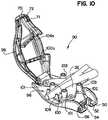
- Fig. 10shows another embodiment 90 of a universal securing device.
- Securing device 90has a base 96 and a cover 98.
- the locating elements extending up from the base 96are locating pegs 100 and each peg is surrounded by a ridge 102 at the base of the peg.
- a front pair 101 and back pair 103 of locating pegsextend from the base 96 and are arranged in a configuration to position and hold a catheter and catheter fitting of various shapes and sizes and prevent substantial movement of such catheters and catheter fittings in various dimensions, similar to locating elements 40 described above.
- a first back locating peg 103may be separated from a second back locating peg 103 by a dimension CC, while a first front locating peg 101 may be separated from a second front locating peg 101 by a dimension DD, as shown in Fig. 11 .
- dimension CCmay be greater than dimension DD.
- dimension CCmay measure about .35 to .39 inches, preferably .36 to .38 inches, or more preferably .37 inches in length and dimension DD may be about .28 to .32 inches, preferably .29 to .31 inches, or more preferably .30 inches in length.
- dimension CCmay be about 130-170% of dimension DD or more preferably about 140-160% of dimension DD.
- the locating pegs 100 positioned closest to the hinge block 62 and located above the arrow 49may be connected generally horizontally by a capture element 104.
- the locating pegs 100 located below the arrow 49 and closest to the latching arms 50may also be connected generally horizontally by a capture element 104.
- Spikes 106may extend up from the surface of the capture elements 104.
- a semicircular trough 108, running generally parallel to the lateral axis X of the base 96 and positioned in front of the locating pegs 100 (as indicated by the arrow 49)may also extend up from the base 86.
- the spikesmay optionally extend up from the surface of the base 86 in an embodiment without capture element 104.
- the cover 98includes a first opening 110 in a front wall 114a and a second opening 112 in a back wall 114b.
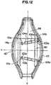
- a first opening 110 in a front wall 114aAs shown in Figs. 12-13 , the cover 98 includes a first opening 110 in a front wall 114a and a second opening 112 in a back wall 114b.
- locating pegs 100aAs best shown in Fig. 12 and with reference to the base 96 in Fig. 11 , provided on the under side of the cover 98 are locating pegs 100a which are capable of fitting inside locating pegs 100 on base 96.
- the locating pegs on cover 98include a front pair 101a and back pair 103a of locating pegs, each with ridges 102a as well at least one capture element 104a running between the locating pegs on the underside of the cover 98 arranged in a configuration that generally mirrors the configuration of locating pegs 100 and capture element 104 on the base 96.
- Spikes 106amay extend up from the capture elements 104a.
- the front pair 101a and/or back pair 103a of locating pegsmay be positioned in between or outside bars 80, which are located on the underside of the cover 98 and run generally parallel to the lateral X axis (shown in Fig. 12 ).
- the capture elements 104 and 104amay be spring molded.
- At least one locating peg 100amay be positioned at least partially on the surface of a bar 80.
- At least one capture element 104amay also be at least partially positioned on the surface of a bar 80.
- ridges 71, each having an angled surface 72,may optionally be provided below latch holes 70.
- the locating pegs 100a on the coverare connected by a capture element 104a which is positioned at an angle of about 1-45° to a longitudinal Y axis across the underside of the cover 98 and locating pegs 100 on the base 96 are connected by a capture element 104 which is positioned at an angle of about 1-45° to a longitudinal Y axis across the base.
- the securing device 90 shown in Figs. 10-15operates in much the same way as the securing device 20, shown in Figs. 1-9 and described above. Additionally, as cover 98 closes onto a catheter fitting 116 (or other catheter fittings of various sizes) which is positioned between the locating elements and latches onto base 96, locating pegs 100a may align with and engage locating pegs 100 as shown in Figs. 14-15 . This helps prevent cover 98 from shifting or moving, making the latching mechanism between latching elements 52 and latch holes 70 even more reliable. Also, spikes 106 and 106a are configured and arranged similar to the spikes in the embodiments of Figs. 1-9 and described above.
- spikes 106 and 106ahelp compress and grip catheter fittings of various shapes and sizes such as catheter fitting 32, (e.g., by compressing the body and/or wings of the catheter fitting) securely holding the catheter fitting 32 in place and preventing substantial movement of the fitting in various dimensions as described above with respect to Figs. 1-9 .
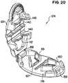
- FIG. 16-20Another embodiment of a securing device 124 is shown in Figs. 16-20 .
- grooves 130are provided on cover 128 which help make the cover more flexible.
- a latch 132 and snap hinge 136are centered at opposite sides of the cover 128, along the lateral X axis of the cover 128.
- Web sections 140run generally parallel to a longitudinal Y axis between column legs 144 and between grooves 130 on the under side of the cover 128.
- the web sections 140include a capture element 142 and elevated ends 145 extending from the web sections 140.
- the device 124may also include a base 126.
- the locating elements 150 on the base 126include a front pair 152 and a back pair 154 of locating elements arranged in a front to back direction as indicated by arrow 49.
- the locating elements 150may be substantially symmetrical side-to-side about the longitudinal axis or centerline Y.
- the locating elements 150help restrain a catheter and catheter fitting of various shapes and sizes and help prevent substantial side-to-side, back-to-front, axial and rotational movement of such catheters and catheter fittings on the base 126.
- a ridge 155At the foot of a locating element 150 is a ridge 155 and positioned in between the front pair 152 and back pair 154 of locating elements is a bar 157 running on either side of the arrow 49 and generally parallel to arrow 49.
- a bottom latch 159 and snap hinge base 158are centered at opposite sides of the base 126, along the lateral X axis of the base 126.
- Side walls 156may extend up form the base along the perimeter of the base 126.
- the locating elements 150are arranged such that a front locating element 152 is separated from a back locating element 154 by a dimension EE which extends from the inner tip of 152 straight back and perpendicular to 154.
- the inner edge of the first or right back locating element 154may be separated from the inner edge of the second or left back locating element 154 by a dimension GG running generally parallel to a lateral axis X.
- the inner edge of the first or right front locating element 152may be separated from the inner edge of the second or left front locating element 152 by a dimension HH running parallel to dimension GG.
- dimension GGmay be greater than dimension HH.
- dimension GGmay be about 130 to 170% of dimension HH or more preferably about 140 to 160% of dimension HH.
- the device 124operates such that the cover 128 is attached by the snap hinge 136 to the snap hinge base 158 of base 126 and the cover 128 can rotate down onto the base 126 into a closed position where the latch 132 and bottom latch 159 engage.
- the capture element 142 on the web sections 140is adapted to contact and compress the top of a catheter fitting held within device 124.
- the capture elements 142help compress and grip catheter fittings of various shapes and sizes (e.g., by compressing the body and/or wings of a catheter fitting) securely holding the catheter fitting in place and preventing substantial movement of the catheter fitting such as in an axial, side-to-side, back-to-front, up and down and rotational direction.
- the capture elementsmay compress the catheter fitting against the ridge 155 and/or bar 157.
- the ends 145 of the web sections 140serve a similar function as the locating elements discussed above as they also help restrain a catheter fitting and help prevent substantial side-to-side, back-to-front, axial and rotational movement of the catheter fitting.
- the web sections 140 including capture elements 142 and ends 145, as well as bars 157 and ridges 155,may be solid or spring molded and may be made of various materials as discussed above.
- a base with no locating elementsmay be used with the cover 128 for compressing and holding a catheter.
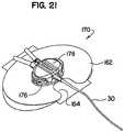
- Fig. 21shows securing device 170 having a base 176 and cover 178.
- the deviceis attached to an adhesive pad 162.
- This embodimentoperates much like the embodiments of Figs. 16-20 described above for securing catheters and catheter fittings having various shapes and sizes.
- the base 176 and cover 178may snap fit together with or without a hinge feature.
- Figs. 22-29show the universal catheter securement device 20 in use with various different types of catheters.
- the wings 200 of the catheter 32are restrained against virtually any longitudinal movement by the front and rear locating elements.
- the wings 200 of the catheterare narrower or smaller, leaving a gap between the locating elements. This would nominally allow the catheter to shift longitudinally under force (e.g., with pulling on the catheter tubes).
- the coveris closed, the catheter body 202 and/or the wings are clamped tightly by the capture elements. This largely prevents any extensive inadvertent and undesirable movement of the catheter, even though there may be no direct physical contact with a front or rear locating element.
- Fig. 30shows an alternative embodiment of a base 180 for use in a securing device.
- the locating elements 182 on the base 180include at least one front wall 183 and a pair of back walls 184 arranged in a front to back direction as indicated by arrow 49.
- the locating elements 182may be substantially symmetrical side-to-side about the longitudinal axis or centerline Y and they are arranged to position and hold catheter and catheter fittings of various shapes and sizes to prevent substantial movement of such catheters and catheter fittings in various dimensions.
- the front wall 183may be angled and a semicircular trough 185 may be positioned slightly forward of the front wall 183 and may be connected to the front wall.
- the back wall 184is connected to a post 186.
- a bottom latch 187 and snap hinge base 188are centered at opposite sides of the base 180, along the lateral X axis of the base 180.
- the base 180may snap fit to a cover with or without a hinge feature.
- Side walls 189may extend up form the base along the perimeter of the base 180 and spikes 190 may extend up from the base and run in a line on either side of arrow 49, between a front wall 183 and back wall 184.
- the base 180can operate in conjunction with a cover in a manner to compress and/or restrain catheters and/or catheter fittings of various shapes and sizes and prevent their substantial movement in various dimensions.
- the locating elements 182are arranged such that a front wall 183 is separated from a back wall 184 by a dimension JJ which extends from a mid-point on an inner surface of the front wall 183, straight back and generally parallel to the longitudinal axis Y, to the post 186.
- a front wall 183may also be separated from a back wall 184 by a dimension KK which extends from the outer edge of the front wall 183 to the outer edge of the back wall 184.
- a first or right post 186may be separated from a second or left post 186 by a dimension LL running generally parallel to a lateral axis X.
- a semicircular trough 185may have a dimension MM running generally parallel to dimension LL.
- dimension JJis greater than dimension KK.
- dimension LLis greater than dimension MM.
- dimension JJmay measure about .33 to .37 inches, preferably .34 to .36 inches, or more preferably .35 inches in length and dimension KK may measure about .31 to .35 inches, preferably .32 to .34 inches, or more preferably .33 inches in length.
- dimension LLmay measure about .41 to .45 inches, preferably .42 to .44 inches, or more preferably .43 inches in length and dimension MM may be about .15 to .19 inches, preferably .16 to .18 inches, or more preferably .17 inches in length.
- the devicemay use a generally plane cover and base, with the device not having locating elements 40 and/or spikes 48.
- the cover and baseact as simple clamping elements to secure the catheter. With sufficient clamping force applied, the cover and base can restrain the catheter against significant movement, without using locating elements, such as walls, posts, etc.
- Force multiplying elementssuch as levers, cams, screw threads, etc. may be used in this type of design to provide adequate clamping force.
- the above securing devicesmay be molded plastic or made of other materials suitable for use with patients. Any of the bases or covers described may be provided in the shapes shown or in other shapes as well, including irregular shapes. Outer walls extending up from a base around the outside of the locating elements may also be provided to help align and engage a cover onto a base. Also, the various embodiments of securing devices described above may be attached to a patient in a variety of ways, e.g., with a pad as shown in Fig. 2 , or with other adhesive means.
- a securing device for holding catheters and the like in placeadvantageously has two parts.
- a base attached to a padforms one part.
- a coveris the other part.
- the covermay optionally be tethered to the base.
- the padpreferably has an adhesive back surface for attaching the pad to the patient's skin.
- the base on the padhas positioning elements such as walls or surfaces adapted to fit securely around a catheter fitting.
- the catheter fittingmay be placed into or onto the base from above. The positioning elements prevent any substantial movement of the catheter fitting, in two dimensions, relative to the base or pad, e.g. in the front/back and left/right side directions.
- the coveris attached to the base over the catheter fitting.
- One or both of the base and coverhave latching elements for holding the cover onto the base.
- the coverprevents movement of the catheter fitting in a third dimension, i.e., vertically up and out of the base. Consequently, after the cover is attached to the base over the catheter fitting, the catheter fitting and the catheter are securely held in place on the patient.
- the cathetermay be released and removed from the base by temporarily disengaging the latching elements.
- the latching elementsmay be disengaged by, for example, squeezing the sides of the cover.
- the cathetercan therefore be quickly and easily attached to or removed from the patient.
- Such devicesmay be used with, e.g., PICC lines, IV catheters, Foley catheters, heart catheters, J-loops, and various other catheters, as well as tubes, cables, lines, and other medical devices.
- Fig. 31shows an embodiment of a securing device 320 having a base 326 attached to a pad 322.
- the pad 322is flexible to conform to the patient's arm or other site.
- the back side of the pad 322preferably has one or more peelable strips over an adhesive layer or surface.
- the specific pad shape and sizeis not essential and various alternatives may be used.
- the pad 322generally is oval or round, and with a major diameter of from about 1-6, 2-5 or 3-4 inches. The pad does not need any suture holes.
- a baseis attached onto the top side of the pad 322 at a generally central location.
- the base 326has positioning walls 350 shaped and dimensioned to fit securely around a fitting 332 on a catheter 330.
- the catheter walls 350are adapted to fit around the curved ends of the fitting plate.
- the walls 350are spaced apart in the back to front direction (indicated by the arrow 356 in Fig. 32 ) by a dimension just nominally greater than the width of the fitting plate 334.
- the walls 350are spaced apart side to side by a dimension nominally greater than the length of the fitting plate.
- outer walls 352extend up from the base 326 around the outside of the positioning walls 350.
- the outer wallsare lower than the positioning walls.
- Latching arms 340extend up generally from opposite sides of the base 326.
- An angled face or surface 344is provided at the top or head 342 of each of the arms 340.
- the base 326may have a tapered or inclined edge or rim 354.
- One or more through holes 346may be provided in the base 326, if desired, for manufacturing purposes.
- An arrow symbol 356may be provided on the base 326 and/or the cover 328, to indicate how the catheter 330 should be installed into the device 320.
- the cover 328has latching arms 366, with an angled surface or face 370 at the outer or lower end 368 of each arm 366, similar to the latching arms 340 on the base 326.
- the arms 366are centered at opposite sides of the cover, along the major axis of the cover.
- Web sections 362run between column legs 360 on the bottom or under side of the cover 328. The column legs extend out beyond the latching arms 366.
- a contact or land surface or area 364 on the web sections 362are adapted to lightly contact the top of the catheter fitting 332 when the cover 328 is attached to the base 326.
- the skin at the securement siteis preferably cleaned.
- the catheter fitting 332is then placed into or onto the base 326, as shown in Fig. 33 .
- Land or boss areas 351may be provided on the floor of the base 326, within the positioning walls 350, as shown in Figs. 33 and 33 . These areas 351 may be used, if desired, to support the catheter fitting 332 off of the floor of the base 326.
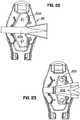
- the cover 328is then attached to the base 326 over the fitting 332, as shown in Fig. 31 .
- the outer walls 352may align with and engage against inner rim surfaces 365 on the cover 328, as shown in Fig. 35 . This interaction, if used, helps to align the cover onto the base, and to securely attach the cover to the base.
- the column legsrest on flat outer areas of the base.
- the column legs 360are dimensioned so that when they bottom out on the base 326, the contact surfaces 364 rest on the catheter fitting 332.
- the legs 360prevent crushing or deformation of the catheter fitting, by keeping the contact surfaces 364 at a specified dimension above the base floor. As a result, the catheter fitting cannot be crushed, even if the cover is forcefully clamped down onto the base.
- the fitting 332is securely held in place (horizontally) on the base between the positioning walls and is held in place vertically between the floor of the base 326 and the contact surfaces 364 of the cover.
- the angled surfaces 344 on the base latching arms 340engage the angled surfaces 370 on the cover latching arms 366.
- the arms 340 and 366are somewhat resilient and can flex slightly under load in the lateral direction.
- the base latching arms 340flex slightly outwardly, and the cover latching arms flex slightly inwardly.
- the surfaces 344 and 370 of the arms 340 and 366slide against and then pass by each other. The arms 340 and 366 then flex back to near their original lateral positions, locking the cover 328 onto the base 326.
- the peel strip(s)are removed from the back of the pad 322, and the pad is placed onto the prepared securement site.
- the device 320then prevents virtually any movement of the catheter fitting 332, which is joined to or part of the catheter 330.
- a cut out 324may be provided at the front of the pad 322 to allow the base 326 to be closer to the incision or catheter entry point.
- the catheter 330may be removed by squeezing the sides of the cover 328 towards each other.
- the cover 328is slightly flexible. Squeezing causes the cover to curve or bow up. As the cover curves, the arms 366 are drawn inwardly enough to pull the ends 368 of the arms 366 on the cover 328 away from the ends 342 of the arms 340 on the base 326. The head or ends 342 and 368 can then pass by each other as the cover is lifted off of the base.
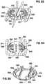
- Figs. 36-38show another embodiment of a securing device 380 for use with a catheter 390 and catheter fitting 392.
- the cover 388has curved contact surfaces 364 matching the top of the fitting 392.
- the base 386has positioning walls 350 adapted to fit around the fitting 392.
- Figs. 39-42show another embodiment of a securing device 400 for use with another type of catheter 410 and catheter fitting 412. As shown in Fig. 40 , the positioning walls 350 on the base 406 are segmented.
- the cover 408, as shown in Fig. 42includes an opening 416 in a rear wall 414.
- Figs. 43-45show another embodiment of a securing device 430 for use with yet another type of catheter 440 and catheter fitting 442.
- four positioning walls 350are provided on the base 436.
- Grooves 444may be provided on the cover 444 to make the cover more flexible.
- ramps or ridges 420may be provided on the base floor near or adjoining one or more of the positioning walls 350. These features may be used to set the orientation of the catheter fitting in the device.
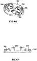
- Figs. 46 and 47show a base 450 similar to the base 436 shown in Fig. 43 .
- the base 450is generally oval shaped as opposed to the more rectangular base 436 shown in Fig. 43 .
- the devices shown in Figs. 36-47operate in the same way as the device 320 shown in Figs. 31-35 and described above.
- the base and cover in each designmay be molded plastic.
- the positioning walls 350may be segmented, as shown in the drawings, or continuous. Indeed, a single continuous positioning wall surrounding the catheter fitting 442 on all sides may be used. Alternatively, multiple short spaced apart wall segments around two, three or more sides of the fitting may also be used.
- the wall segmentsmay be various shapes, including generally rectangular, as shown in Figs. 45-47 , as well as round, square, hexagonal, etc.
- Positioning or locating elements, such as the walls 350may optionally also be provided on the cover.
- Moveable or adjustable positioning elements or wall segmentsmay also alternatively be provided on the base. If used, these may have a single direction or ratchet feature, so that they can move only inwardly to contact the sides of the catheter fitting. Moveable positioning elements may allow use of a single device with more than one specific type of catheter
Landscapes
- Health & Medical Sciences (AREA)
- Life Sciences & Earth Sciences (AREA)
- Animal Behavior & Ethology (AREA)
- Engineering & Computer Science (AREA)
- Anesthesiology (AREA)
- Biomedical Technology (AREA)
- Heart & Thoracic Surgery (AREA)
- Hematology (AREA)
- General Health & Medical Sciences (AREA)
- Public Health (AREA)
- Veterinary Medicine (AREA)
- Pulmonology (AREA)
- Biophysics (AREA)
- Vascular Medicine (AREA)
- Media Introduction/Drainage Providing Device (AREA)
Description
- The invention relates to a system for securing a medical device in place on a patient. Typically, the invention may be used for securing a catheter, tube or other elongated medical device to a patient.
- It is often necessary to introduce fluids and liquid medications directly into a blood vessel of a patient. A simple intravenous (IV) line is usually acceptable for short term general use. IV lines are typically placed onto a patient's arm and secured with tape. For longer term and more specialized needs, catheters or other devices are used. A catheter is essentially a tube inserted through an incision in the skin into a blood vessel in the patient's body, generally without surgery. Peripherally inserted central catheters (PICCs) are frequently used to provide medications or fluids to home care patients over longer periods of time. PICCs may also be used for frequent blood sampling.
- A PICC line and similar catheters may remain in place in a patient for several weeks or months. It is important that movement of the catheter be minimized. If the catheter is not secured in place, it may be inadvertently displaced from the intended location. Consequently, medication delivered through the PICC line may then be released at an incorrect position within the blood vessel. Repeated back and forth catheter movement, or pistoning, can cause irritation of the blood vessel, disrupt proper introduction of medications to the patient, and increase the potential for bleeding or infection at the catheter incision site. If extensive movement occurs, the PICC line could even come out of the patient, interrupting delivery of medication and requiring re-insertion, often with hospitalization.
- In the past, catheters were simply taped into place on the patient's skin. However, taping is time consuming and labor intensive. Tape also collects bacteria and must be frequently removed and replaced. More importantly, taping is not necessarily effective in securing a catheter in place. Sutures have also been used to attach a catheter to a patient. With sutures, the catheter is stitched onto the skin. Sutures, however, can also be a source of infection, can cause pain and inflammation, and can make it more difficult to clean around the incision site. Sutures also require time and skill to place, and can cause scarring.
- More recently, manufactured catheter anchors or securing devices have come into more widespread use. These devices are specifically designed to secure specific catheters in place. While various designs have been used, these devices generally have an adhesive-backed pad that bonds to the skin over a large area. The catheter is secured into or onto a catheter anchor designed for holding the catheter. These anchoring devices have various advantages over tape or sutures. However, engineering design challenges remain in providing reliable, secure and efficient anchoring devices. Further, because existing anchoring devices are generally designed for a specific type of catheter, multiple anchors may be needed to accommodate use of different types of catheters, e.g., in hospitals and clinical settings. This adds to the cost and complexity of sourcing, inventory, storage, and selection of the anchoring devices. Accordingly, improved anchoring devices are needed.
- Document
WO 9920334 US 2005192539 A1 relates to a method of securing a medical article to the body of a patient in which an anchoring device comprising an anchor and a retainer is used. The retainer is attached to an upper surface of the anchor and comprises a base, a cover and a post. The base is disposed on the upper surface of the anchor and the cover is connected to the base so as to move between an open and a closed position. When the cover is in the closed position, it lies above at least part of the base. The post is attached movably to either the base or the cover and is arranged so as to lie at least partially between the cover and the base when the cover is in the closed position. When securing a medical article, the cover is placed in the open position and the medical article placed onto the retainer. The cover may then be closed over the medical article and the anchoring device attached to the patient.GB 2344054 A FR 2852520 A1 - The invention relates to an anchoring system according to claim 1. Further embodiments of the invention are disclosed in the dependent claims, the description, and the figures. A substantially universal catheter securing device may have a base with one or more locating elements, such as walls or pegs. The locating elements on the base may be positioned and arranged for securing and positioning catheters and catheter fittings of various shapes and sizes. The base, which may be attached to an adhesive pad, is connected or connectable to a cover having capture elements. The capture elements may grip and compress a catheter fitting when the cover is in a closed position, thereby helping secure a catheter and catheter fitting of various sizes within the universal catheter securing device. In an alternative design, the locating elements can be omitted, with the catheter secured in the device largely via only compression and friction forces resulting from clamping the catheter between the base and a cover. Another design for holding catheters and the like in place may include locating or positioning elements on a base and contact surfaces on a cover.
- In the drawings, the same element number indicates the same element in each of the views.
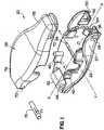
Fig. 1 is an exploded perspective view of a securing device.Fig. 2 is a top and front perspective view of the device shown inFig. 1 , with the cover lifted in an open position and base attached to an adhesive pad.Fig. 3 is a plan view of the top surface of the base and locating elements of a securing device shown inFigs. 1-2 .Fig. 4 is top and front perspective view of the base shown inFigs. 1-3 .Fig. 5 is a back perspective view showing the bottom surface of the base shown inFig. 4 .Fig. 6 is a plan view of the under side of the cover shown inFigs. 1-2 and5 .Fig. 7 is a top and back perspective view of the under side of the cover shown inFigs. 1-2 and5 .Fig. 8 is a cross section of a side perspective view of the securing device shown inFigs. 1-2 and5 in a closed position.Fig. 9 is a top and front perspective view of the device shown inFig. 1-2 and5 in a closed position.Fig. 10 is a top and front perspective view of another embodiment of a securing device with the cover lifted in an open position.Fig. 11 is a top perspective view of the base of the securing device shown inFig. 10 .Fig. 12 is a plan view of the under side of the cover of the securing device shown inFig. 10 .Fig. 13 is a top and back perspective view of the under side of the cover of the securing device shown inFig. 10 .Fig. 14 is a plan view of the securing device shown inFig. 10 in the closed position, holding a catheter fitting representative of various catheter fitting shapes and sizes.Fig. 15 is a top and front perspective view of the securing device shown inFig. 10 in the closed position, holding an exemplary catheter fitting.Fig. 16 is a top perspective view of the cover of another embodiment of a securing device.Fig. 17 is a perspective view of the under side of the cover shown inFig. 16 .Fig. 18 is a side view of the cover shown inFig. 16 .Fig. 19 is a top perspective view of a base for attachment to the cover ofFigs. 16-18 .Fig. 20 is a top and front perspective view of the cover and base shown inFigs. 16-19 fastened together to form a securing device.Fig. 21 is a top and front perspective view of a securing device attached to a pad.Figs. 22-29 are plan views of various catheter fittings positioned on the base and within the locating elements of the securing devices shown inFigs. 1-2 and10 .Fig. 30 is a top plan view of another base for use in a securing device.Fig. 31 is a top and front perspective view of another embodiment of a securing device. The pad shown inFig. 31 is used on each of the various securing devices described below. However, the pad as shown inFig. 31 is omitted from the remaining drawings, to allow for better illustration of the other components.Fig. 32 is an exploded perspective view of the device shown inFig. 31 .Fig. 33 is a top perspective view of the device shown inFig. 31 , with the cover removed.Fig. 34 is a plan view of the base shown inFigs. 32 and33 .Fig. 35 is a perspective view of the under side of the cover shown inFigs. 31 and 32 .Fig. 36 is an exploded top and front perspective view of another securing device design useable with another type of catheter.Fig. 37 is a front view of the device shown inFig. 36 .Fig. 38 is a front and bottom perspective view of the device shown inFigs. 36 and 37 .Fig. 39 is a top and side exploded perspective view of another securing device design useable with another type of catheter.Fig. 40 is a top and front view of the device shown inFig. 39 .Fig. 41 is a top perspective view of the base shown inFigs. 39 and 40 .Fig. 42 is perspective view of the under side of the cover shown inFigs. 39 and 40 .Fig. 43 is a top and side exploded perspective view of another securing device design useable with another type of catheter.Fig. 44 is a bottom view of the base shown inFig. 43 .Fig. 45 is perspective view of the under side of the cover used with the base shown inFig. 43 .Fig. 46 is a perspective view of an alternative base, similar to the base shown inFig. 43 , and having a generally oval shape.Fig. 47 is a side view of the base shown inFig. 46 .- A universal securing device for holding catheters of various designs may include a base and a cover. The cover may be connected to the base by a hinge which allows the cover to be lifted open or pushed down into a closed position, to secure a catheter fitting or similar device. The base and/or cover have locating elements configured and arranged to fit around catheters and catheter fittings of various shapes and sizes. The catheter fitting is placed into or onto the base from above. The locating elements prevent substantial movement of a catheter and/or catheter fitting in multiple dimensions.
In this specification the following non-SI units are used - Inches. This non-SI unit may be converted to the respective SI or metric unit, this being mm, according to the following conversion conversion factor: 1 Inch = 25.4 mm. - Latching elements, which may be located on squeezing arms hold the cover onto the base. Capture elements may be located on the under side of the cover to compress a catheter fitting, securely holding it in place against the base, in the closed position. The catheter may be held securely in place on a patient once the securing device is attached to the patient. The catheter can be removed from the base by disengaging the latching elements, for example, here by squeezing the squeezing arms toward each other. Thus, a catheter and catheter fitting of various shapes and sizes can be securely held by a single securing device and can be quickly and easily attached to or removed from the patient. The devices described herein may be used with, e.g., PICC lines, IV catheters, Foley catheters, heart catheters, J-loops, and various others. In addition to a catheter, the present securing device may be used to secure other tubes, cables, wires, and various other medical devices as well.
- Turning now to the drawings, as shown in
Figs. 1-9 , a securingdevice 20 has abase 26. As shown inFig. 2 , thebase 26 may be contoured and may have one ormore locating elements 40 which are shaped and dimensioned to be positioned around and hold catheters and catheter fittings of various shapes and sizes, such as catheter fitting 32 andcatheter 30. InFigs. 2-5 and8-9 , the locatingelements 40 include rectangular shaped walls, however, locating elements may be round, square, hexagonal, etc. and they may take on various forms in addition to walls such as pegs, columns, etc. The base may vary in size and typically is about 2-3 inches long and about 1-2 inches wide. - Referring to
Figs. 3-4 , the locatingelements 40 extend up from thebase 26. In this particular embodiment, the locating elements include at least onefront wall 41 and a pair ofback walls 46. The front and back walls are spaced apart in a front to back direction as indicated byarrow 49, which runs along a longitudinal axis identified by the imaginary line marked Y shown inFig. 3 . Afront wall 41 shown inFigs. 3-4 is made up of at least onecurved end wall 42, at least oneangled front wall 43, at least oneelbow 44. Asemicircular trough 45 may be positioned slightly forward of the angledfront wall 43 as indicated byarrow 49 and may be connected to theelbow 44. A raised post may extend up from at least oneelbow 44. Theback walls 46 are preferably angled and are each connected to apost 47. The first andsecond posts 47 connected to eitherback wall 46, can be the same size or they may differ in size. In general, the locatingelements 40 may be substantially symmetrical side-to-side about the longitudinal axis or centerline Y. The locatingelements 40 are arranged and positioned to allow PICCs and other catheters of various shapes and sizes to be placed onto thebase 26 and held within the securingdevice 20. The locatingelements 40 are arranged in a manner to help position catheters and catheter fittings of various shapes and sizes and prevent substantial movement of a catheter and catheter fitting in various dimensions relative to the base, e.g., side-to-side and back-to-front, axial movement, as well as rotational movement. - Referring to
Figs 3-4 , in one embodiment the locatingelements 40 are arranged such that afront wall 41 is separated from theback wall 46 by a dimension AA which extends straight back, parallel to the longitudinal Y axis, from the rear most tip ofcurved end wall 42 offront wall 41 to theback wall 46. Thefront wall 41 may also be separated from theback wall 46 by a dimension BB which extends from the rear most tip ofcurved end wall 42 offront wall 41, straight back and perpendicular to theback wall 46. Also, the inner edge of the first orleft post 47 may be separated from the inner edge of the second orright post 47 by a dimension CC running generally parallel to a lateral axis X. Also, the first orleft elbow 44 may be separated from the second orright elbow 44 by a dimension DD running parallel to dimension CC. - In one embodiment, dimension AA may be less than dimension BB. Also, dimension CC may be greater than dimension DD. In another embodiment dimension AA may measure about .34 to .38 inches, preferably .35 to .37 inches, or more preferably .36 inches in length. Dimension BB may measure about .37 to .41 inches, preferably .38 to .40 inches, or more preferably .39 inches in length. Also, dimension CC may measure about .35 to .39 inches, preferably .36 to .38 inches, or more preferably .37 inches in length and dimension DD may be about .28 to .32 inches, preferably .29 to .31 inches, or more preferably .30 inches in length. In another embodiment, dimension CC may be about 130 to 170% of dimension DD or more preferably about 140 to 160% of dimension DD.
- Referring to
Figs. 3-4 , the base may also include one ormore spikes 48 extending up from the base. In one embodiment, a line of posts or spikes 48, are located on a line betweenfront wall 41 andback wall 46, on both sides of axis Y. The line of posts or spikes 48 may be generally parallel to each other and to the longitudinal axis Y or at an angle of, e.g., 1-45° to the longitudinal axis Y. Thespikes 48 may extend up from the surface of the base or from capture elements running generally parallel to each other and to the longitudinal axis Y or at an angle of, e.g., 1-45° to the longitudinal axis Y, on both sides of axis Y between afront wall 41 and aback wall 46. - Referring to
Fig. 1 , thebase 26 may have two squeezingarms 50 or optionally the base 26 may have onearm 50 that is resilient and flexible and asecond arm 50 which is generally fixed and rigid. The base 26 may also have ahinge block 62 located on the base 26 at an opposite end from the squeezingarms 50. The squeezingarms 50 are flexible and have latchingelements 52 andsidewalls 57. Anangled surface 56 may be provided at theend 54 of each of the latchingelements 52 facing the inner surface of a squeezingarm wall 57, withgrip ribs 59 on the outside of each squeezingarm wall 57. As shown inFig. 3-4 , a throughhole 66 may be provided, if desired, in thebase 26, behind thehinge block 62. Anarrow symbol 49 may be printed, molded or otherwise provided on thebase 26 and/or thecover 28, running along a longitudinal Y axis, as shown inFig. 3 . The arrow indicates in which direction the catheter should be installed into theuniversal securing device 20. - As shown in
Fig. 1 , thecover 28 has latch holes 70, and hingepinholes 73 located at opposite ends of thecover 28.Ridges 71, each having anangled surface 72, may optionally be provided below the latch holes 70, as shown, e.g., in the embodiment ofFig. 10 . As shown inFig. 2 , thecover 28 is connected to thebase 26 by ahinge 60.Fig. 1 shows that the hinge may be provided by pressing ahinge pin 75 throughhinge pinholes 73 and through an alignedhinge pin slot 64 which runs through thehinge block 62. Thehinge pin 75 may have a round diameter and may include one or more, preferably four, raised crush ribs 77 which serve to hold thehinge pin 75 in place by friction after being press fit through thehinge pinholes 73 andhinge pin slot 64. The hinge may also take various other forms, for example, a hinge may be formed by tongue and groove elements. A hinge may also be formed by a snap fitting mechanism between a latch or snap hinge and snap hinge base. Various types of hinges or pivot joints may be used. Most designs will have a hinge at one side of the device and a latching element at the other side, with the cover pivoting open and closed. However, an alternative design may have a separate snap on cover having a latch or lock element at either end of the cover. - As best shown in
Figs. 6-7 , thecover 28 includes afirst opening 83 in afront wall 84 and asecond opening 85 in aback wall 86. Thecover 28 may have one ormore bars 80 which run in a direction DL on the underside of thecover 28, generally parallel to the lateral X axis. The center area of thebars 80 may be recessed compared to the ends of thebars 80 in order to accommodate the height of various catheter fittings. Thebars 80 may be connected by one ormore capture elements 82 on the underside of thecover 28. Thecapture elements 82 may be generally parallel to each other and to the longitudinal Y axis, or at an angle of, e.g., 1-45° to the longitudinal axis. The ends of thecapture element 82 may rest at least partially on the surface of thebars 80. One or more posts or spikes 88 may extend from thecapture elements 82. In the design shown inFig. 7 , threespikes 88 are spaced evenly apart and extend up from a centerelevated segment 86 on the surface of thecapture element 82. Optionally, thecapture elements 82 may run along the underside of a cover where the cover has no bars. - Turning momentarily to
Fig. 2 thecapture element 82 is adapted to contact and compress catheter fittings of various shapes and sizes such as catheter fitting 32, e.g., by compressing the wings and/or body of a catheter fitting 32 once the catheter fitting 32 is placed onto thebase 26 within the locatingelements 40 and thecover 28 is attached to the base 26 in a closed position.Capture elements 82 may be solid or spring molded as leaf springs or foam springs.Capture elements 82 may also be an elastomer. The surface of acapture element 82 may optionally be provided with cones or serrated teeth to assist with compression and gripping of acatheter fitting 32. Asingle capture element 82 ormultiple capture elements 82 may be used. In the specific design shown ifFig. 2 , two capture elements are provided. - Referring again to
Figs. 2 and4 , in use, after the catheter has been inserted into the patient, the skin at the securement site is preferably cleaned. The catheter fitting 32 is then placed into or onto thebase 26, within the locatingelements 40. Thecover 28, which is attached to thebase 26 via thehinge 60, can be closed down, by pivoting about the ends of thehinge pin 75 positioned inside thehinge block 62, over and onto thecatheter fitting 32. Thecurved end wall 42,elbow 44 andsemicircular trough 45, all serve to center and align thecover 28 as thecover 28 is moved down and over the front wall, onto thebase 26, and into the closed position. The outside surface of thecurved end wall 42,elbow 44 andsemicircular trough 45 may abut against the inner surface of thefront wall 84 of thecover 28 as thecover 28 moves down and into the closed position. Also, a raised post which may be located atop one ormore elbows 44 may also help align thecover 28 as it closes onto thebase 26, and it too may optionally abut against the inner surface of thefront wall 84 of thecover 28 as thecover 28 moves down and into the closed position. Also, one or both of theposts 47 connected to aback wall 46 may serve to center and align thecover 28 as thecover 28 is moved down and over aback wall 46 and the first andsecond posts 47. The first andsecond posts 47 andback walls 46 may abut against the inner surface of thecover 28 as thecover 28 moves down and into the closed position. These alignment features help to properly locate the cover on the base as the cover is closed. - In a closed position (as shown in
Fig. 9 ), thetop end 78 of thecover 28 attaches to thebase 26 within the squeezingarm walls 57. The latch holes 70 in thefront wall 84 andback wall 86 of thecover 28 engage the latchingelements 52 on the squeezingarms 50. This facilitates the secure attachment of thecover 28 to thebase 26, placing the securingdevice 20 in a closed position. Thecover 28 rests on the flat and contoured outer areas of thebase 26, around thefront wall 41 and back walls 46 (not shown because enclosed by cover), and on the flat area of the squeezingarms 50. - In a closed position, the
spikes 88 on one ormore capture elements 82 may compress down on the wings and/or body of thecatheter fitting 32. The wings of the catheter fitting 32, which are generally somewhat flexible or compliant, are thereby pinched or held between thespikes 88 ofcapture element 82 and thespikes 48 extending up from the surface of thebase 26. Thespikes 88 and thespikes 48 are located to grip and compress the wings and/or body of the catheter fitting. As shown ifFig. 8 , thespikes 88 and spikes 48 are preferably about .04 inches in height and some vertical space may exist between the tips of thespikes 88 and thespikes 48 when thecover 28 is in the closed position. Thespikes 88 may also be slightly offset by .02-.12 inches to the inside of thespikes 48, i.e., toward thearrow 49. Thespikes 88 may also be similarly offset to the front of thespikes 48, as indicated byarrow 49. This applies a pinching or bending effect on the wings of the catheter, in addition to compression. By having the top and bottom spikes offset from each other, thedevice 20 can better secure catheters having wings of varying thickness. - The
capture elements 82 thereby secure a catheter fitting 32 within securingdevice 20 by preventing substantial movement of catheter fitting 32 in an axial, side-to-side, back-to-front, up and down and rotational direction. Thecapture element 82 may be resilient and flexible, capable of holding and griping catheter fittings of various thicknesses. Thecapture element 82 may also be solid. Thecover 28 may be used in conjunction with abase 26, having locatingelements 40 and spikes 48, for securing a catheter fitting. - In another embodiment, the
cover 28 may be used in conjunction with abase 26 for compressing and holding a catheter body on a patient. The base may or may not have locating elements. In use, this embodiment would function by placing a catheter on abase 26 and compressing or pinching the catheter body between an underside surface of acover 28, e.g., againstcapture elements 82 or any part of the underside of the cover, and a top surface of the base with sufficient force to hold or restrain the catheter in place without substantial movement in various dimensions relative to the base and cover, e.g., axial, side-to-side, back-to-front, up and down and rotational. This arrangement, for compressing a catheter body of various shapes and sizes between a cover and base could be performed with any of the additional embodiments described below as well. - Referring again to
Figs. 2 and4 , as thetop end 78 of thecover 28 is moved down onto the base 26 from an open position to a closed position, theangled surfaces 56 on theends 54 of the latchingelements 52 engage the inner surface of thefront wall 84 andback wall 86, below the latch holes 70 on thecover 28. Alternatively, theangled surfaces 56 on theends 54 of the latchingelements 52 may engage theangled surfaces 72 ofridges 71, positioned below the latch holes 70 on thecover 28, e.g., as shown in the embodiment ofFig. 10 . The latchingelements 52 are somewhat resilient and can flex slightly under load in the longitudinal direction (along axis Y as shown inFig. 1 ). As a result, as thecover 28 is moved down into engagement with thebase 26, the latchingelements 52 flex slightly inwardly toward each other. The angled surfaces 56 of the latchingelements 52 and the inner surface of the front andback walls cover 28 or theangled surfaces 72 of theridges 71 slide against each other and pass by each other. The latchingelements 52 then flex back to near their original longitudinal positions, forcing the ends 54 of the latching elements through the latch holes 70 in thecover 28 and locking thecover 28 onto thebase 26. Thecatheter securing device 20 is then attached to the patient at the prepared securement site, usually via an adhesive pad. The securingdevice 20 then prevents virtually any movement of the catheter fitting 32 and adjoiningcatheter 30 within the securing device. - The
catheter 30 may be removed by squeezing the squeezingarms 50 together, towards each other. One or both of the squeezingarms 50 may be resilient and flexible such that they may flex in the longitudinal direction. The squeezingarms 50 may be squeezed together by applying a force in the longitudinal direction, generally on the area of thegrip ribs 59 located on the outer surface of the squeezingarm walls 57. Squeezing also causes the latchingelements 52 on the squeezingarms 50 to move longitudinally toward each other, resulting in theends 54 of the latchingelements 52 moving back through and out of the latch holes 70. The latchingelements 52 move toward each other such that thecover 28 can be lifted away from the latchingelements 52. Theangled surface 56 and angledsurface 72 and/or inner surface of thecover 28 pass by each other as thecover 28 is pivoted up and off of thebase 26. - The securing device described above may be attached to a patient in a variety of ways. As shown in
Fig. 1 , abase 26 may be attached to apad 162 which is flexible to conform to the patient's arm or other site. The pad could be a hydro colloidal pad. The specific pad shape and size is not essential and various alternatives may be used. InFig. 1 , thepad 162 is generally oval or round and it can also be a small footprint of abase 26. The back side of thepad 162 preferably has one or more peelable strips over an adhesive layer or surface. The peel strips may be removed from the back of thepad 162, and the pad placed onto a prepared securement site. A cut out 164 may be provided at the front of thepad 162 to allow the base 26 to be closer to the incision or catheter entry point. Alternatively, the securing device may be affixed directly to a patient by applying adhesive tape around the device and against the patient's arm or other site. Fig. 10 shows anotherembodiment 90 of a universal securing device. Securingdevice 90 has abase 96 and acover 98. In this embodiment, as shown inFig. 11 , the locating elements extending up from the base 96 are locatingpegs 100 and each peg is surrounded by aridge 102 at the base of the peg. Afront pair 101 andback pair 103 of locating pegs extend from thebase 96 and are arranged in a configuration to position and hold a catheter and catheter fitting of various shapes and sizes and prevent substantial movement of such catheters and catheter fittings in various dimensions, similar to locatingelements 40 described above.- As with the locating
elements 40 shown above inFig. 3 , a firstback locating peg 103 may be separated from a secondback locating peg 103 by a dimension CC, while a firstfront locating peg 101 may be separated from a secondfront locating peg 101 by a dimension DD, as shown inFig. 11 . In one embodiment dimension CC may be greater than dimension DD. In another embodiment dimension CC may measure about .35 to .39 inches, preferably .36 to .38 inches, or more preferably .37 inches in length and dimension DD may be about .28 to .32 inches, preferably .29 to .31 inches, or more preferably .30 inches in length. In another embodiment, dimension CC may be about 130-170% of dimension DD or more preferably about 140-160% of dimension DD. - In addition, in
Fig. 11 , the locating pegs 100 positioned closest to thehinge block 62 and located above thearrow 49, may be connected generally horizontally by acapture element 104. The locating pegs 100 located below thearrow 49 and closest to the latchingarms 50 may also be connected generally horizontally by acapture element 104.Spikes 106 may extend up from the surface of thecapture elements 104. Asemicircular trough 108, running generally parallel to the lateral axis X of thebase 96 and positioned in front of the locating pegs 100 (as indicated by the arrow 49) may also extend up from thebase 86. The spikes may optionally extend up from the surface of the base 86 in an embodiment withoutcapture element 104. - As shown in
Figs. 12-13 , thecover 98 includes afirst opening 110 in a front wall 114a and asecond opening 112 in aback wall 114b. As best shown inFig. 12 and with reference to the base 96 inFig. 11 , provided on the under side of thecover 98 are locatingpegs 100a which are capable of fitting inside locatingpegs 100 onbase 96. The locating pegs oncover 98 include a front pair 101a and backpair 103a of locating pegs, each with ridges 102a as well at least onecapture element 104a running between the locating pegs on the underside of thecover 98 arranged in a configuration that generally mirrors the configuration of locatingpegs 100 andcapture element 104 on thebase 96.Spikes 106a may extend up from thecapture elements 104a. The front pair 101a and/orback pair 103a of locating pegs may be positioned in between or outside bars 80, which are located on the underside of thecover 98 and run generally parallel to the lateral X axis (shown inFig. 12 ). Thecapture elements peg 100a may be positioned at least partially on the surface of abar 80. At least onecapture element 104a may also be at least partially positioned on the surface of abar 80. Father, with reference toFig. 10 ,ridges 71, each having anangled surface 72, may optionally be provided below latch holes 70. - In one embodiment, the locating
pegs 100a on the cover are connected by acapture element 104a which is positioned at an angle of about 1-45° to a longitudinal Y axis across the underside of thecover 98 and locatingpegs 100 on thebase 96 are connected by acapture element 104 which is positioned at an angle of about 1-45° to a longitudinal Y axis across the base. - The securing
device 90 shown inFigs. 10-15 operates in much the same way as the securingdevice 20, shown inFigs. 1-9 and described above. Additionally, ascover 98 closes onto a catheter fitting 116 (or other catheter fittings of various sizes) which is positioned between the locating elements and latches ontobase 96, locatingpegs 100a may align with and engage locatingpegs 100 as shown inFigs. 14-15 . This helps preventcover 98 from shifting or moving, making the latching mechanism between latchingelements 52 and latch holes 70 even more reliable. Also, spikes 106 and 106a are configured and arranged similar to the spikes in the embodiments ofFigs. 1-9 and described above. Thus, spikes 106 and 106a help compress and grip catheter fittings of various shapes and sizes such as catheter fitting 32, (e.g., by compressing the body and/or wings of the catheter fitting) securely holding the catheter fitting 32 in place and preventing substantial movement of the fitting in various dimensions as described above with respect toFigs. 1-9 . - Another embodiment of a securing
device 124 is shown inFigs. 16-20 . As best shown inFig. 17 ,grooves 130 are provided oncover 128 which help make the cover more flexible. Alatch 132 and snaphinge 136 are centered at opposite sides of thecover 128, along the lateral X axis of thecover 128.Web sections 140 run generally parallel to a longitudinal Y axis betweencolumn legs 144 and betweengrooves 130 on the under side of thecover 128. Theweb sections 140 include acapture element 142 andelevated ends 145 extending from theweb sections 140. - As shown in
Fig. 19 , thedevice 124 may also include abase 126. The locatingelements 150 on the base 126 include afront pair 152 and aback pair 154 of locating elements arranged in a front to back direction as indicated byarrow 49. In general, the locatingelements 150 may be substantially symmetrical side-to-side about the longitudinal axis or centerline Y. The locatingelements 150 help restrain a catheter and catheter fitting of various shapes and sizes and help prevent substantial side-to-side, back-to-front, axial and rotational movement of such catheters and catheter fittings on thebase 126. At the foot of a locatingelement 150 is aridge 155 and positioned in between thefront pair 152 andback pair 154 of locating elements is abar 157 running on either side of thearrow 49 and generally parallel toarrow 49. Abottom latch 159 and snaphinge base 158 are centered at opposite sides of thebase 126, along the lateral X axis of thebase 126.Side walls 156 may extend up form the base along the perimeter of thebase 126. - In one embodiment the locating
elements 150 are arranged such that afront locating element 152 is separated from a back locatingelement 154 by a dimension EE which extends from the inner tip of 152 straight back and perpendicular to 154. Also, the inner edge of the first or right back locatingelement 154 may be separated from the inner edge of the second or left back locatingelement 154 by a dimension GG running generally parallel to a lateral axis X. Also, the inner edge of the first or rightfront locating element 152 may be separated from the inner edge of the second or leftfront locating element 152 by a dimension HH running parallel to dimension GG. In one embodiment, dimension GG may be greater than dimension HH. In another embodiment dimension GG may be about 130 to 170% of dimension HH or more preferably about 140 to 160% of dimension HH. - As shown in
Fig. 20 , thedevice 124 operates such that thecover 128 is attached by thesnap hinge 136 to thesnap hinge base 158 ofbase 126 and thecover 128 can rotate down onto the base 126 into a closed position where thelatch 132 andbottom latch 159 engage. In a closed position thecapture element 142 on theweb sections 140 is adapted to contact and compress the top of a catheter fitting held withindevice 124. Thecapture elements 142 help compress and grip catheter fittings of various shapes and sizes (e.g., by compressing the body and/or wings of a catheter fitting) securely holding the catheter fitting in place and preventing substantial movement of the catheter fitting such as in an axial, side-to-side, back-to-front, up and down and rotational direction. The capture elements may compress the catheter fitting against theridge 155 and/orbar 157. The ends 145 of theweb sections 140 serve a similar function as the locating elements discussed above as they also help restrain a catheter fitting and help prevent substantial side-to-side, back-to-front, axial and rotational movement of the catheter fitting. Theweb sections 140 includingcapture elements 142 and ends 145, as well asbars 157 andridges 155, may be solid or spring molded and may be made of various materials as discussed above. Optionally, a base with no locating elements may be used with thecover 128 for compressing and holding a catheter. Fig. 21 shows securing device 170 having a base 176 andcover 178. The device is attached to anadhesive pad 162. This embodiment operates much like the embodiments ofFigs. 16-20 described above for securing catheters and catheter fittings having various shapes and sizes. Thebase 176 and cover 178 may snap fit together with or without a hinge feature.Figs. 22-29 show the universalcatheter securement device 20 in use with various different types of catheters. With some catheters, as shown inFigs. 22 ,24 ,27 and29 , thewings 200 of thecatheter 32 are restrained against virtually any longitudinal movement by the front and rear locating elements. With other catheters, such as shown inFigs. 23 ,26 and28 , thewings 200 of the catheter are narrower or smaller, leaving a gap between the locating elements. This would nominally allow the catheter to shift longitudinally under force (e.g., with pulling on the catheter tubes). However, when the cover is closed, thecatheter body 202 and/or the wings are clamped tightly by the capture elements. This largely prevents any extensive inadvertent and undesirable movement of the catheter, even though there may be no direct physical contact with a front or rear locating element.Fig. 30 shows an alternative embodiment of a base 180 for use in a securing device. The locatingelements 182 on the base 180 include at least onefront wall 183 and a pair ofback walls 184 arranged in a front to back direction as indicated byarrow 49. In general, the locatingelements 182 may be substantially symmetrical side-to-side about the longitudinal axis or centerline Y and they are arranged to position and hold catheter and catheter fittings of various shapes and sizes to prevent substantial movement of such catheters and catheter fittings in various dimensions. Thefront wall 183 may be angled and asemicircular trough 185 may be positioned slightly forward of thefront wall 183 and may be connected to the front wall. Theback wall 184 is connected to apost 186. Abottom latch 187 and snaphinge base 188 are centered at opposite sides of the base 180, along the lateral X axis of the base 180. The base 180 may snap fit to a cover with or without a hinge feature.Side walls 189 may extend up form the base along the perimeter of the base 180 and spikes 190 may extend up from the base and run in a line on either side ofarrow 49, between afront wall 183 andback wall 184. The base 180 can operate in conjunction with a cover in a manner to compress and/or restrain catheters and/or catheter fittings of various shapes and sizes and prevent their substantial movement in various dimensions.- In one embodiment the locating
elements 182 are arranged such that afront wall 183 is separated from aback wall 184 by a dimension JJ which extends from a mid-point on an inner surface of thefront wall 183, straight back and generally parallel to the longitudinal axis Y, to thepost 186. Afront wall 183 may also be separated from aback wall 184 by a dimension KK which extends from the outer edge of thefront wall 183 to the outer edge of theback wall 184. Also, a first orright post 186 may be separated from a second orleft post 186 by a dimension LL running generally parallel to a lateral axis X. Further, asemicircular trough 185 may have a dimension MM running generally parallel to dimension LL. In one embodiment, dimension JJ is greater than dimension KK. In one embodiment, dimension LL is greater than dimension MM. In another embodiment dimension JJ may measure about .33 to .37 inches, preferably .34 to .36 inches, or more preferably .35 inches in length and dimension KK may measure about .31 to .35 inches, preferably .32 to .34 inches, or more preferably .33 inches in length. Also, dimension LL may measure about .41 to .45 inches, preferably .42 to .44 inches, or more preferably .43 inches in length and dimension MM may be about .15 to .19 inches, preferably .16 to .18 inches, or more preferably .17 inches in length. - In an alternative design, the device may use a generally plane cover and base, with the device not having locating
elements 40 and/or spikes 48. In this design, the cover and base act as simple clamping elements to secure the catheter. With sufficient clamping force applied, the cover and base can restrain the catheter against significant movement, without using locating elements, such as walls, posts, etc. Force multiplying elements, such as levers, cams, screw threads, etc. may be used in this type of design to provide adequate clamping force. - The above securing devices may be molded plastic or made of other materials suitable for use with patients. Any of the bases or covers described may be provided in the shapes shown or in other shapes as well, including irregular shapes. Outer walls extending up from a base around the outside of the locating elements may also be provided to help align and engage a cover onto a base. Also, the various embodiments of securing devices described above may be attached to a patient in a variety of ways, e.g., with a pad as shown in
Fig. 2 , or with other adhesive means. - In other embodiments, a securing device for holding catheters and the like in place advantageously has two parts. A base attached to a pad forms one part. A cover is the other part. The cover may optionally be tethered to the base. The pad preferably has an adhesive back surface for attaching the pad to the patient's skin. The base on the pad has positioning elements such as walls or surfaces adapted to fit securely around a catheter fitting. The catheter fitting may be placed into or onto the base from above. The positioning elements prevent any substantial movement of the catheter fitting, in two dimensions, relative to the base or pad, e.g. in the front/back and left/right side directions. The cover is attached to the base over the catheter fitting. One or both of the base and cover have latching elements for holding the cover onto the base. The cover prevents movement of the catheter fitting in a third dimension, i.e., vertically up and out of the base. Consequently, after the cover is attached to the base over the catheter fitting, the catheter fitting and the catheter are securely held in place on the patient. The catheter may be released and removed from the base by temporarily disengaging the latching elements. The latching elements may be disengaged by, for example, squeezing the sides of the cover. The catheter can therefore be quickly and easily attached to or removed from the patient. Such devices may be used with, e.g., PICC lines, IV catheters, Foley catheters, heart catheters, J-loops, and various other catheters, as well as tubes, cables, lines, and other medical devices.
- For example,
Fig. 31 shows an embodiment of a securingdevice 320 having a base 326 attached to apad 322. Thepad 322 is flexible to conform to the patient's arm or other site. The back side of thepad 322 preferably has one or more peelable strips over an adhesive layer or surface. The specific pad shape and size is not essential and various alternatives may be used. In the example shown inFig. 31 , thepad 322 generally is oval or round, and with a major diameter of from about 1-6, 2-5 or 3-4 inches. The pad does not need any suture holes. - As shown in
Figs. 31-34 , a base is attached onto the top side of thepad 322 at a generally central location. Thebase 326 has positioningwalls 350 shaped and dimensioned to fit securely around a fitting 332 on acatheter 330. For thecatheter 330 shown inFigs. 32 and33 , fourseparate positioning walls 350 are used. In this case, thecatheter walls 350 are adapted to fit around the curved ends of the fitting plate. Thewalls 350 are spaced apart in the back to front direction (indicated by thearrow 356 inFig. 32 ) by a dimension just nominally greater than the width of thefitting plate 334. Similarly, thewalls 350 are spaced apart side to side by a dimension nominally greater than the length of the fitting plate. - Referring to
Figs. 32-34 ,outer walls 352 extend up from thebase 326 around the outside of thepositioning walls 350. The outer walls are lower than the positioning walls. Latchingarms 340 extend up generally from opposite sides of thebase 326. An angled face orsurface 344 is provided at the top orhead 342 of each of thearms 340. The base 326 may have a tapered or inclined edge orrim 354. One or more throughholes 346 may be provided in thebase 326, if desired, for manufacturing purposes. Anarrow symbol 356 may be provided on thebase 326 and/or thecover 328, to indicate how thecatheter 330 should be installed into thedevice 320. - As shown in
Figs. 32 and35 , thecover 328 has latchingarms 366, with an angled surface or face 370 at the outer orlower end 368 of eacharm 366, similar to the latchingarms 340 on thebase 326. In theoblong cover 328 shown inFig. 35 , thearms 366 are centered at opposite sides of the cover, along the major axis of the cover.Web sections 362 run betweencolumn legs 360 on the bottom or under side of thecover 328. The column legs extend out beyond the latchingarms 366. A contact or land surface orarea 364 on theweb sections 362 are adapted to lightly contact the top of the catheter fitting 332 when thecover 328 is attached to thebase 326. - In use, after the catheter has been placed, the skin at the securement site is preferably cleaned. The catheter fitting 332 is then placed into or onto the
base 326, as shown inFig. 33 . Land orboss areas 351 may be provided on the floor of thebase 326, within thepositioning walls 350, as shown inFigs. 33 and 33 . Theseareas 351 may be used, if desired, to support the catheter fitting 332 off of the floor of thebase 326. Thecover 328 is then attached to the base 326 over the fitting 332, as shown inFig. 31 . Theouter walls 352 may align with and engage against inner rim surfaces 365 on thecover 328, as shown inFig. 35 . This interaction, if used, helps to align the cover onto the base, and to securely attach the cover to the base. The column legs rest on flat outer areas of the base. - The
column legs 360 are dimensioned so that when they bottom out on thebase 326, the contact surfaces 364 rest on thecatheter fitting 332. Thelegs 360 prevent crushing or deformation of the catheter fitting, by keeping the contact surfaces 364 at a specified dimension above the base floor. As a result, the catheter fitting cannot be crushed, even if the cover is forcefully clamped down onto the base. The fitting 332 is securely held in place (horizontally) on the base between the positioning walls and is held in place vertically between the floor of thebase 326 and the contact surfaces 364 of the cover. - As the cover is moved down onto the
base 326, theangled surfaces 344 on thebase latching arms 340 engage theangled surfaces 370 on thecover latching arms 366. This provides for a cover self aligning operation. Thearms base latching arms 340 flex slightly outwardly, and the cover latching arms flex slightly inwardly. Thesurfaces arms arms cover 328 onto thebase 326. The peel strip(s) are removed from the back of thepad 322, and the pad is placed onto the prepared securement site. Thedevice 320 then prevents virtually any movement of the catheter fitting 332, which is joined to or part of thecatheter 330. A cut out 324 may be provided at the front of thepad 322 to allow the base 326 to be closer to the incision or catheter entry point. - The
catheter 330 may be removed by squeezing the sides of thecover 328 towards each other. Thecover 328 is slightly flexible. Squeezing causes the cover to curve or bow up. As the cover curves, thearms 366 are drawn inwardly enough to pull theends 368 of thearms 366 on thecover 328 away from theends 342 of thearms 340 on thebase 326. The head or ends 342 and 368 can then pass by each other as the cover is lifted off of the base. Figs. 36-38 show another embodiment of a securingdevice 380 for use with a catheter 390 and catheter fitting 392. Thecover 388 has curved contact surfaces 364 matching the top of the fitting 392. Thebase 386 has positioningwalls 350 adapted to fit around the fitting 392.Figs. 39-42 show another embodiment of a securingdevice 400 for use with another type ofcatheter 410 and catheter fitting 412. As shown inFig. 40 , thepositioning walls 350 on thebase 406 are segmented. Thecover 408, as shown inFig. 42 , includes anopening 416 in arear wall 414.Figs. 43-45 show another embodiment of a securingdevice 430 for use with yet another type of catheter 440 and catheter fitting 442. In this design, fourpositioning walls 350 are provided on thebase 436.Grooves 444 may be provided on thecover 444 to make the cover more flexible. As shown inFigs. 41 ,43 and46 , ramps orridges 420 may be provided on the base floor near or adjoining one or more of thepositioning walls 350. These features may be used to set the orientation of the catheter fitting in the device.Figs. 46 and 47 show a base 450 similar to the base 436 shown inFig. 43 . Thebase 450 is generally oval shaped as opposed to the morerectangular base 436 shown inFig. 43 .- The devices shown in
Figs. 36-47 operate in the same way as thedevice 320 shown inFigs. 31-35 and described above. The base and cover in each design may be molded plastic. Thepositioning walls 350 may be segmented, as shown in the drawings, or continuous. Indeed, a single continuous positioning wall surrounding the catheter fitting 442 on all sides may be used. Alternatively, multiple short spaced apart wall segments around two, three or more sides of the fitting may also be used. The wall segments may be various shapes, including generally rectangular, as shown inFigs. 45-47 , as well as round, square, hexagonal, etc. Positioning or locating elements, such as thewalls 350, may optionally also be provided on the cover. Moveable or adjustable positioning elements or wall segments may also alternatively be provided on the base. If used, these may have a single direction or ratchet feature, so that they can move only inwardly to contact the sides of the catheter fitting. Moveable positioning elements may allow use of a single device with more than one specific type of catheter. - Thus novel devices and methods have been described. Various changes and modifications may of course be made without departing from the scope of the invention. The invention, therefore, should not be limited, except to the following claims, and their equivalents.
Claims (19)
- An anchoring system for securing a catheter to the body of a patient, comprising:a catheter fitting (32) on a medical line, the catheter fitting having a body and a pair of outwardly extending wings;a base (26) having a front wall (41) and a pair of back walls (46) disposed relative to the base so as to generally define an area therebetween receiving the body of the catheter fitting, the front wall and the pair of back walls being spaced apart to receive the wings of the catheter fitting therebetween and to fit securely around the wings of the catheter fitting to inhibit at least longitudinal movement of the secured wings relative to the base;a cover (28) being attachable to the base, the cover being movable to an engaged position in which at least a portion of each of the front wall and the pair of back walls is disposed between the cover and the base; andat least one latching element (52) and at least one latch hole (70) which releasably secure together the base and the cover in the engaged position.
- An anchoring system as in Claim 1, wherein each of the front wall (41) and the pair of back walls (46) is disposed relative to the base so as to contact the pair of outwardly extending wings.
- An anchoring system as in Claim 1, wherein the cover (28) rests on flat and contoured outer areas of the base (26), around the front wall (41) and the pair of back walls (46), and on a flat area of the at least one latching element (52).
- An anchoring system as in Claim 1, wherein the front wall (41) and the pair of back walls (46) extend up from the base (26).
- An anchoring system as in Claim 1, wherein at least a portion of each of the front wall (41) and the pair of back walls (46) has a rectangular shape.
- An anchoring system as in Claim 1, wherein the at least one latching element (52) is configured to interact with the cover (28) when the cover is in the engaged position.
- An anchoring system as in Claim 6, wherein the at least one latch hole (70) is configured to interact with the at least one latching element (52) when the cover (28) is in the engaged position.
- An anchoring system as in Claim 7, wherein the at least one latch hole (70) receives a portion of the at least one latching element (52) at least when the cover (28) is in the engaged position.
- An anchoring system as in Claim 6, wherein the at least one latching element (52) has an angled surface (56) which locks to the cover (28) when the cover is in the engaged position.
- An anchoring system as in Claim 6, wherein the cover (28) and the at least one latching element (52) are configured to flex slightly when the cover is moved to the engaged position.
- An anchoring system as in Claim 6, wherein the front wall (41) and the pair of back walls (46) are disposed on the base so as to be spaced from the at least one latching element (52).
- An anchoring system as in Claim 1, wherein the cover (28) comprises a plurality of contact surfaces (364) disposed so as to face the base (26) when the cover is in the engaged position.
- An anchoring system as in Claim 12, wherein the plurality of contact surfaces (364) inhibits the catheter from being crushed between the base (26) and the cover (28).
- An anchoring system as in Claim 12, wherein the plurality of contact surfaces (364) is disposed above the base (26).
- An anchoring system as in Claim 1, wherein each of the front wall (41) and the pair of back walls (46) is disposed between the cover (28) and the base (26) when the cover is in the engaged position.
- An anchoring system as in Claim 1, wherein the cover (28) contacts at least the body of the catheter fitting when the cover is in the engaged position.
- An anchoring system as in Claim 1, wherein the front wall (41) and the pair of back walls (46) inhibit lateral movement of the secured wing relative to the base.
- An anchoring system as in Claim 6, wherein the at least one latching element (52) is separate from the front wall (41) and the pair of back walls (46).
- An anchoring system as in Claim 6, wherein the at least one latching element (52) is located on a latching arm (50).
Applications Claiming Priority (3)
| Application Number | Priority Date | Filing Date | Title |
|---|---|---|---|
| US75838606P | 2006-01-12 | 2006-01-12 | |
| US86509506P | 2006-11-09 | 2006-11-09 | |
| PCT/US2007/000969WO2007082093A2 (en) | 2006-01-12 | 2007-01-11 | Universal catheter securement device |
Publications (3)
| Publication Number | Publication Date |
|---|---|
| EP1988945A2 EP1988945A2 (en) | 2008-11-12 |
| EP1988945A4 EP1988945A4 (en) | 2010-11-17 |
| EP1988945B1true EP1988945B1 (en) | 2021-08-18 |
Family
ID=38257059
Family Applications (1)
| Application Number | Title | Priority Date | Filing Date |
|---|---|---|---|
| EP07717867.1AActiveEP1988945B1 (en) | 2006-01-12 | 2007-01-11 | Universal catheter securement device |
Country Status (10)
| Country | Link |
|---|---|
| US (3) | US8016792B2 (en) |
| EP (1) | EP1988945B1 (en) |
| JP (1) | JP2009523495A (en) |
| KR (1) | KR20090019762A (en) |
| AU (1) | AU2007204820B2 (en) |
| CA (1) | CA2641882A1 (en) |
| ES (1) | ES2895905T3 (en) |
| MX (1) | MX2008009054A (en) |
| NZ (1) | NZ570223A (en) |
| WO (1) | WO2007082093A2 (en) |
Families Citing this family (82)
| Publication number | Priority date | Publication date | Assignee | Title |
|---|---|---|---|---|
| US6572588B1 (en) | 2000-03-10 | 2003-06-03 | Venetec International, Inc. | Medical anchoring system |
| US20070016069A1 (en) | 2005-05-06 | 2007-01-18 | Sorin Grunwald | Ultrasound sensor |
| US20090118612A1 (en) | 2005-05-06 | 2009-05-07 | Sorin Grunwald | Apparatus and Method for Vascular Access |
| US20120010572A1 (en)* | 2005-10-24 | 2012-01-12 | Tionne Bennett | Intravenous Catheter Protective Cover |
| USD1089641S1 (en) | 2005-10-24 | 2025-08-19 | Tionne A. Bennett | Intravenous catheter cover |
| EP1988945B1 (en) | 2006-01-12 | 2021-08-18 | Venetec International, Inc. | Universal catheter securement device |
| US9138560B2 (en)* | 2006-01-12 | 2015-09-22 | Venetec International, Inc. | Universal catheter securement device |
| JP5660890B2 (en) | 2007-06-26 | 2015-01-28 | バソノバ・インコーポレイテッドVasonova, Inc. | Vascular access and guidance system |
| SG183085A1 (en) | 2008-06-11 | 2012-08-30 | Bracco Diagnostics Inc | Shielding assemblies for infusion systems |
| US8317674B2 (en) | 2008-06-11 | 2012-11-27 | Bracco Diagnostics Inc. | Shielding assemblies for infusion systems |
| US9480821B2 (en) | 2008-06-30 | 2016-11-01 | Venetec International, Inc. | Anchoring system for a medical article |
| US8795237B2 (en)* | 2008-09-30 | 2014-08-05 | Covidien Lp | Transparent catheter securement system |
| US8419689B2 (en) | 2008-09-30 | 2013-04-16 | Covidien Lp | Enclosing package for medical port and cover |
| US8216181B2 (en)* | 2008-11-19 | 2012-07-10 | Bracco Diagnostics, Inc. | Apparatus and methods for support of a membrane filter in a medical infusion system |
| WO2010085865A1 (en)* | 2009-01-28 | 2010-08-05 | Gusmao Marcos De Oliveira | Device for fastening metallic guides and balloon catheters for carrying out medical procedures involving percutaneous vascular surgery |
| EP2277581A1 (en) | 2009-07-20 | 2011-01-26 | Ostergaard, Hans Jorgen Lund | A device for fastening and protecting a catheter unit |
| US10537714B2 (en) | 2009-11-11 | 2020-01-21 | Venetec International, Inc. | Stabilizing device for an extension set |
| FR2954168B1 (en)* | 2009-12-17 | 2012-12-07 | Dentalhitec | CYLINDRICAL SUPPORT FOR A PHARMACEUTICAL PRODUCT CONTAINER FOR ROTATION |
| WO2012015440A1 (en)* | 2010-07-30 | 2012-02-02 | Venetec International, Inc. | Securement device |
| GB201013490D0 (en)* | 2010-08-11 | 2010-09-22 | Goma Medical Ltd | Catheter clamp |
| EP2637568B1 (en) | 2010-11-08 | 2017-04-12 | Vasonova, Inc. | Endovascular navigation system |
| US8591495B2 (en) | 2011-02-23 | 2013-11-26 | Fischell Innovations, Llc | Introducer sheath with thin-walled shaft |
| US8262625B1 (en)* | 2011-05-11 | 2012-09-11 | Fischell Innovations, Llc | Introducer sheath having a hemostasis valve with an adhesive means for attachment to the skin |
| US8535294B2 (en) | 2011-06-01 | 2013-09-17 | Fischell Innovations Llc | Carotid sheath with flexible distal section |
| US8936576B2 (en) | 2011-09-15 | 2015-01-20 | Interrad Medical, Inc. | System for anchoring medical devices |
| JP5818614B2 (en) | 2011-09-28 | 2015-11-18 | 日本コヴィディエン株式会社 | Catheter fixture |
| JP5818613B2 (en) | 2011-09-28 | 2015-11-18 | 日本コヴィディエン株式会社 | Catheter fixture |
| CN104245032A (en)* | 2011-12-16 | 2014-12-24 | 因赛特拉医药公司 | catheter fastening device |
| US8556859B2 (en) | 2011-12-21 | 2013-10-15 | Securcath LLC | Securement device for medical fixtures |
| US8747428B2 (en) | 2012-01-12 | 2014-06-10 | Fischell Innovations, Llc | Carotid sheath with entry and tracking rapid exchange dilators and method of use |
| BR112014017932A2 (en)* | 2012-01-19 | 2017-06-27 | Insightra Medical Inc | catheter clamping devices |
| EP2846701A4 (en) | 2012-05-07 | 2016-01-27 | Vasonova Inc | Right atrium indicator |
| CN104602730B (en) | 2012-08-31 | 2018-01-02 | 3M创新有限公司 | Medical product fixed system including bracket and fin |
| JP2015526256A (en)* | 2012-08-31 | 2015-09-10 | スリーエム イノベイティブ プロパティズ カンパニー | Medical article securing system with indicia and method of using the same |
| EP2890425B1 (en) | 2012-08-31 | 2021-01-20 | 3M Innovative Properties Company | Medical article securement systems and methods of using same |
| USD737435S1 (en)* | 2012-09-18 | 2015-08-25 | 3M Innovative Properties Company | Securement device |
| JP6289475B2 (en)* | 2012-10-01 | 2018-03-07 | メンリッケ・ヘルス・ケア・アーベー | Wound therapy device |
| JP2016510676A (en) | 2013-03-15 | 2016-04-11 | ヴェネテック・インターナショナル,インコーポレーテッド | Fixing device with integrated strap and dressing |
| US8858505B1 (en)* | 2013-04-08 | 2014-10-14 | Jesse Michael Justus | Catheter injection port lock |
| US9381321B2 (en)* | 2013-05-03 | 2016-07-05 | Interrad Medical, Inc. | Systems and methods for anchoring medical devices |
| US20160106958A1 (en)* | 2013-05-05 | 2016-04-21 | Resqdevices Pty Ltd | An Intravenous Cannula Retainer |
| CA2920641C (en) | 2013-08-26 | 2022-08-30 | Merit Medical Systems, Inc. | Sheathless guide, rapid exchange dilator and associated methods |
| US10335322B2 (en) | 2013-08-26 | 2019-07-02 | Lightside Md, Llc | Adhesive support devices and methods of making and using them |
| US9981111B2 (en)* | 2013-09-10 | 2018-05-29 | Novum Vascular, Llc | Two-piece catheter securement system and method for using same |
| EP3060136A4 (en) | 2013-10-18 | 2017-06-21 | Lightside Md, Llc | Support devices and methods of making and using them |
| US8979805B1 (en)* | 2013-11-26 | 2015-03-17 | Avent, Inc. | Catheter connector securement device |
| WO2015123684A1 (en)* | 2014-02-17 | 2015-08-20 | The Johns Hopkins University | Securement device with attachable members for use with a catheter |
| US20170072168A1 (en)* | 2014-03-05 | 2017-03-16 | 3M Innovative Properties Company | Graphic for medical article securement systems and methods of using same |
| US9192741B1 (en) | 2014-06-06 | 2015-11-24 | Sasan Najibi | Catheter and wire holding device |
| KR101696778B1 (en)* | 2015-01-28 | 2017-01-16 | (주)월드씨앤피 | Safety cap for needle |
| US20170165437A1 (en) | 2015-12-15 | 2017-06-15 | Bert Kamolsit Lopansri | Tamper-resistant enclosures for fluid lines |
| CA3011594A1 (en) | 2016-01-15 | 2017-07-20 | Harris Skeele Corporation D/B/A Simplerlinks | Medical timing device and method having single action triggering for activation and lock conditions |
| EP3403144A4 (en)* | 2016-01-15 | 2019-09-04 | Harris Skeele Corporation D/B/A Simplerlinks | Medical timing device and method having single action triggering for activation and lock conditions |
| CA3018780A1 (en)* | 2016-03-23 | 2017-09-28 | John Robinson | Medical component securement device |
| CN109475681B (en) | 2016-05-13 | 2021-12-07 | C·R·巴德股份有限公司 | Catheter securement device including guide nose |
| AU2017332260B2 (en) | 2016-09-20 | 2022-10-20 | Bracco Diagnostics Inc. | Radioisotope delivery system with multiple detectors to detect gamma and beta emissions |
| US10173035B2 (en) | 2016-12-27 | 2019-01-08 | Vasonics, Llc | Catheter housing |
| USD960115S1 (en) | 2017-04-20 | 2022-08-09 | University Of Tennessee Research Foundation | Tampering detection enclosure |
| USD960114S1 (en) | 2017-04-20 | 2022-08-09 | University Of Tennessee Research Foundation | Tampering detection enclosure |
| USD826875S1 (en)* | 2017-04-20 | 2018-08-28 | University Of Tennessee Research Foundation | Tampering detection clamping box for ingress and egress lines |
| CN110678219A (en) | 2017-04-28 | 2020-01-10 | 美国医疗设备有限公司 | Interposer with partially annealed reinforcement element and related systems and methods |
| JP7216022B2 (en) | 2017-05-30 | 2023-01-31 | ベラノ バスキュラー,インコーポレイテッド | Stabilization devices for vascular access and methods of using stabilization devices |
| US11191939B2 (en) | 2017-11-30 | 2021-12-07 | Velano Vascular, Inc. | Stabilizing connector devices for vascular access and methods of using the same |
| KR200491366Y1 (en)* | 2018-01-24 | 2020-03-26 | 주식회사 유니메딕스 | Fixing means for iv catheter |
| KR200491367Y1 (en)* | 2018-01-24 | 2020-03-26 | 주식회사 유니메딕스 | Fixing means for cv catheter |
| DK3776598T3 (en) | 2018-03-28 | 2022-08-01 | Bracco Diagnostics Inc | SYSTEMS AND TECHNIQUES FOR CALIBRATION OF RADIOISOTOPE DELIVERY SYSTEMS USING A GAMMA DETECTOR |
| KR102733368B1 (en) | 2018-03-28 | 2024-11-21 | 브라코 다이어그노스틱스 아이엔씨. | Early detection of end-of-life of radioisotope generators |
| US11628276B2 (en) | 2018-06-25 | 2023-04-18 | Vasonics, Inc. | Catheter securement, stabilization, and antimicrobial device |
| CN118001551A (en) | 2018-09-28 | 2024-05-10 | 威蓝诺血管股份有限公司 | Devices and methods for drawing blood through a closed system intravenous catheter |
| CN109621158B (en)* | 2018-11-30 | 2021-06-15 | 3M创新有限公司 | Catheter securement assembly |
| WO2020198059A1 (en) | 2019-03-22 | 2020-10-01 | Becton, Dickinson And Company | Stabilization device, system, and methods thereof for integrated catheters |
| WO2020214856A1 (en) | 2019-04-17 | 2020-10-22 | Bard Access Systems, Inc. | Catheter securement device including extended anchor pad and release liner clasping features |
| CN110165435B (en)* | 2019-05-08 | 2024-05-14 | 厦门广泓工贸有限公司 | Electric jointing clamp |
| KR102086445B1 (en)* | 2019-07-05 | 2020-03-09 | 김용현 | Cover for medicine transfer tube device and medicine transfer tube device set including the same |
| KR102456519B1 (en)* | 2019-09-23 | 2022-10-20 | 김응석 | Hook-type catheter stabilizer and hook-type device for fixing pipe |
| JP7592705B2 (en)* | 2019-10-16 | 2024-12-02 | エフ. ホフマン-ラ ロシュ アーゲー | Medical Device Cradle |
| USD930831S1 (en)* | 2020-03-05 | 2021-09-14 | Jim Benton | Microbial barrier tubing clamp |
| WO2021207726A1 (en)* | 2020-04-10 | 2021-10-14 | University Of Florida Research Foundation, Incorporated | Sheath/catheter securing device |
| US20240000524A1 (en)* | 2021-01-14 | 2024-01-04 | Corindus, Inc. | System and apparatus for manipulating an elongated medical device in a robotic catheter-based procedure system |
| KR102588892B1 (en)* | 2021-06-29 | 2023-10-13 | (재)예수병원유지재단 | Fixing device for cartheter |
| US20240285909A1 (en)* | 2023-02-28 | 2024-08-29 | Becton, Dickinson And Company | Catheter Component Securement Apparatus and Associated System |
| WO2024206853A2 (en)* | 2023-03-31 | 2024-10-03 | Forcast Orthopedics, Inc. | Wearable medical device |
Family Cites Families (166)
| Publication number | Priority date | Publication date | Assignee | Title |
|---|---|---|---|---|
| US2525398A (en) | 1948-02-02 | 1950-10-10 | Arthur L Collins | Hypodermic syringe holder and guide |
| US2533961A (en) | 1949-09-29 | 1950-12-12 | Wilfrid J Rousseau | Intravenous needle immobilizer |
| US2707953A (en) | 1952-07-15 | 1955-05-10 | Abbott Lab | Transfusion equipment |
| FR1184139A (en) | 1957-10-09 | 1959-07-17 | Porges Sa | Fastening cap for tubes used in medicine and surgery |
| US3064648A (en) | 1958-04-16 | 1962-11-20 | Abbott Lab | Intravenous needle assembly |
| US3059645A (en) | 1960-11-28 | 1962-10-23 | Paul A Hasbrouck | Adjustable clamp |
| US3167072A (en) | 1962-10-11 | 1965-01-26 | Stone Hester Ellen | Intravenous needle and flow tube stabilizing means |
| US3482569A (en) | 1967-03-15 | 1969-12-09 | Scholl Mfg Co Inc | Surgical pads |
| US3529597A (en) | 1968-04-19 | 1970-09-22 | George T Fuzak | Fingertip bandage |
| US3602227A (en) | 1969-07-18 | 1971-08-31 | Daniel E Andrew | Endotracheal tube clamp |
| US3630195A (en) | 1970-02-04 | 1971-12-28 | Deseret Pharma | Infusion tube holder and method |
| US3682173A (en) | 1970-10-16 | 1972-08-08 | Vicra Sterile Inc | Separable catheter insertion device |
| US3677250A (en) | 1971-02-11 | 1972-07-18 | Morton I Thomas | Tabbed anchoring tape means |
| US3766915A (en) | 1971-12-21 | 1973-10-23 | Illinois Tool Works | Plastic needle holder |
| US3847370A (en) | 1972-02-16 | 1974-11-12 | Horizon Ind Ltd | Tube servicing device |
| US3834380A (en) | 1972-11-15 | 1974-09-10 | W Boyd | Holder for intravenous injection cannula and tubing |
| DE2305896C3 (en) | 1973-02-07 | 1975-11-20 | C.H. Boehringer Sohn, 6507 Ingelheim | Indwelling venous catheter with an inner needle |
| US3896527A (en) | 1973-05-23 | 1975-07-29 | Cincinnati Biomedical Inc | Unitary clamp |
| US3973565A (en) | 1973-07-20 | 1976-08-10 | Everett Medical Products Limited | Winged cannula with skin securing means |
| US4020835A (en) | 1973-08-16 | 1977-05-03 | Boehringer Ingelheim Gmbh | Catheter placement assembly |
| US3856020A (en) | 1973-09-17 | 1974-12-24 | S Kovac | Trocar-catheter assembly |
| US3900026A (en) | 1973-11-19 | 1975-08-19 | William H Wagner | Device for holding and protecting intravenous injection needles |
| US3942228A (en) | 1974-07-19 | 1976-03-09 | Buckman Thomas P | Tubing clamp |
| CH596843A5 (en) | 1976-02-12 | 1978-03-31 | Intermedicat Gmbh | |
| US4059105A (en) | 1976-03-24 | 1977-11-22 | Omnimed, Inc. | Cannula securing device |
| US4057066A (en) | 1976-09-02 | 1977-11-08 | Taylor Harry E | Catheter holder for securing a urethral catheter to a patient |
| US4082094A (en) | 1976-09-13 | 1978-04-04 | Dailey Calvin L | Locking device for intravenous insert |
| US4114618A (en) | 1976-12-15 | 1978-09-19 | Vargas Jorge J | Catheter assembly |
| US4142527A (en) | 1977-02-07 | 1979-03-06 | Garcia Nelson C | Endotracheal tube holder |
| US4316461A (en) | 1977-02-22 | 1982-02-23 | Marais Henri J | Intravenous vascular stabilizer |
| US4129128A (en) | 1977-02-23 | 1978-12-12 | Mcfarlane Richard H | Securing device for catheter placement assembly |
| US4133307A (en) | 1977-05-09 | 1979-01-09 | Ness Richard A | Traction device |
| US4193174A (en) | 1978-04-11 | 1980-03-18 | Portex, Inc. | Lever and fulcrum clamping assembly |
| US4250880A (en) | 1979-06-08 | 1981-02-17 | Whitman Medical Corporation | Stabilizing fitting for an intravenous catheter |
| BE887056Q (en) | 1979-01-19 | 1981-05-04 | Whitman Med Corp | STABILIZATION MOUNT FOR AN INTRAVENOUS CATHETER |
| US4397647A (en) | 1979-01-19 | 1983-08-09 | Whitman Medical Corporation | Catheter stabilization fitting having a snap-over cover |
| US4362156A (en) | 1979-04-18 | 1982-12-07 | Riverain Corporation | Intravenous infusion assembly |
| US4248229A (en) | 1979-05-16 | 1981-02-03 | Miller Roscoe E | Enema tip retention apparatus |
| US4496348A (en) | 1979-11-29 | 1985-01-29 | Abbott Laboratories | Venipuncture device |
| US4324236A (en) | 1979-12-03 | 1982-04-13 | Whitman Medical Corp. | Fitting for use in performing a vascular puncture |
| US4326519A (en) | 1980-02-21 | 1982-04-27 | Abbott Laboratories | Venipuncture device |
| US4333468A (en) | 1980-08-18 | 1982-06-08 | Geist Robert W | Mesentery tube holder apparatus |
| GB2086466A (en) | 1980-10-08 | 1982-05-12 | Wallace Ltd H G | Security clamp for surgical device |
| US4392853A (en) | 1981-03-16 | 1983-07-12 | Rudolph Muto | Sterile assembly for protecting and fastening an indwelling device |
| DE3117416C2 (en) | 1981-05-02 | 1983-10-06 | Reiner Dr. 3320 Salzgitter Nessler | Venous catheter |
| US4449975A (en) | 1981-11-09 | 1984-05-22 | Perry Michael K | Intravenous anchor and wound shield |
| US4453933A (en) | 1981-11-24 | 1984-06-12 | Speaker Mark G | Intravenous device |
| US4480639A (en) | 1982-01-18 | 1984-11-06 | Peterson Edward D | Medical tube retaining device |
| US4516968A (en) | 1982-09-28 | 1985-05-14 | Marshall Charles A | Catheter shield and method of use |
| US4517971A (en) | 1982-11-22 | 1985-05-21 | Sorbonne Robert L | Guard for venipuncture site and catheter retainer |
| US5344414A (en) | 1983-01-24 | 1994-09-06 | Icu Medical Inc. | Medical connector |
| US4474559A (en) | 1983-03-03 | 1984-10-02 | The Cleveland Clinic Foundation | Home parenteral nutrition trainer |
| US4563177A (en) | 1983-12-22 | 1986-01-07 | Kamen Dean L | Catheter stabilization pad |
| US4955864A (en) | 1984-08-02 | 1990-09-11 | Hajduch James D | Tube holding clamp |
| US4660555A (en) | 1984-09-21 | 1987-04-28 | Payton Hugh W | Oxygen delivery and administration system |
| US4650473A (en) | 1985-04-15 | 1987-03-17 | Warner-Lambert Company | Suturing saddle |
| US5037397A (en) | 1985-05-03 | 1991-08-06 | Medical Distributors, Inc. | Universal clamp |
| US4633863A (en) | 1985-09-27 | 1987-01-06 | Filips Chester P | Arterial anchor bandage |
| US4711636A (en) | 1985-11-08 | 1987-12-08 | Bierman Steven F | Catheterization system |
| JPS62281965A (en) | 1986-05-29 | 1987-12-07 | テルモ株式会社 | Catheter and catheter fixing member |
| US4869465A (en) | 1986-06-24 | 1989-09-26 | Mordechai Yirmiyahu | Power-operated spreader tool |
| US4762513A (en) | 1986-07-03 | 1988-08-09 | Mattel, Inc. | Reconfigurable walking toy with gear mechanism |
| US4863432A (en) | 1986-09-10 | 1989-09-05 | Critikon, Inc. | Winged catheter assembly |
| US4742824A (en) | 1986-11-19 | 1988-05-10 | Hugh W. Payton | Oxygen tube support patch |
| US4997421A (en) | 1986-12-10 | 1991-03-05 | Dale Medical Products, Inc. | IV connector lock and stabilizer |
| US4826486A (en) | 1986-12-10 | 1989-05-02 | Dale Medical Products, Inc. | IV connector lock and stabilizer |
| US4896465A (en) | 1987-08-27 | 1990-01-30 | Robert Rhodes | Retainer apparatus |
| US4826466A (en) | 1987-09-11 | 1989-05-02 | Arco Industries Corporation | Steering column boot |
| US4808162A (en) | 1988-01-19 | 1989-02-28 | Ruth Oliver | Gastrotomy tube stabilizer |
| US4880412A (en) | 1988-02-09 | 1989-11-14 | Sol Weiss | Tube insertion apparatus |
| US4823789A (en) | 1988-02-16 | 1989-04-25 | Genetic Laboratories, Inc. | Nose tube anchoring strip |
| US4852844A (en) | 1988-04-25 | 1989-08-01 | Villaveces James W | Device for aiding in preparation of intravenous therapy |
| US4932943A (en) | 1988-05-23 | 1990-06-12 | Hollister Incorporated | Nasogastric tube holding device |
| US4952207A (en) | 1988-07-11 | 1990-08-28 | Critikon, Inc. | I.V. catheter with self-locating needle guard |
| US4857058A (en) | 1988-07-11 | 1989-08-15 | Payton Hugh W | Support patch for intravenous catheter |
| US4919654A (en) | 1988-08-03 | 1990-04-24 | Kalt Medical Corporation | IV clamp with membrane |
| US5000741A (en) | 1988-08-22 | 1991-03-19 | Kalt Medical Corporation | Transparent tracheostomy tube dressing |
| US4944728A (en) | 1988-10-17 | 1990-07-31 | Safe Medical Devices, Inc. | Intravenous catheter placement device |
| US4898587A (en) | 1988-11-15 | 1990-02-06 | Mera Csaba L | Intravenous line stabilizing device |
| US5073166A (en) | 1989-02-15 | 1991-12-17 | Medical Innovations Corporation | Method and apparatus for emplacement of a gastrostomy catheter |
| US4897082A (en) | 1989-03-20 | 1990-01-30 | Becton, Dickinson And Company | Apparatus for providing a suture tab |
| US5527293A (en) | 1989-04-03 | 1996-06-18 | Kinetic Concepts, Inc. | Fastening system and method |
| US5084026A (en) | 1989-07-14 | 1992-01-28 | Shapiro Robert A | Intravenous apparatus holder |
| US5456671A (en) | 1989-07-24 | 1995-10-10 | Bierman; Steven F. | Catheter anchoring system |
| US5314411A (en) | 1989-07-24 | 1994-05-24 | Steven F. Bierman, M.D. | Catheterization system with universal retention device and method of use |
| US6290676B1 (en) | 1989-07-24 | 2001-09-18 | Venetec International, Inc. | Catheter anchoring system |
| US5192273A (en) | 1989-07-24 | 1993-03-09 | Steven F. Bierman | Catheterization system |
| US5578013A (en) | 1989-07-24 | 1996-11-26 | Venetec International, Inc. | Catheter anchoring system |
| US5354282A (en) | 1990-05-04 | 1994-10-11 | Bierman Steven F | Catheter anchoring system |
| US5112313A (en) | 1989-08-11 | 1992-05-12 | Sallee Patricia L | IV cover/protector |
| US5195981A (en) | 1989-12-18 | 1993-03-23 | Johnson Melissa C | Holder for elongated members |
| US5098399A (en) | 1990-02-07 | 1992-03-24 | Tollini Dennis R | Medical securing tape |
| US4976700A (en) | 1990-02-07 | 1990-12-11 | Tollini Dennis R | Medical securing tape |
| US5156641A (en) | 1990-03-07 | 1992-10-20 | Mayo Foundation For Medical Education And Research | Naso-gastric catheter anchor system |
| US5137519A (en) | 1990-03-12 | 1992-08-11 | Cordis Corporation | Catheter retention collar and support |
| US5395344A (en) | 1990-06-08 | 1995-03-07 | Genetic Laboratories Wound Care, Inc. | Catheter anchoring device |
| US5073170A (en) | 1990-08-09 | 1991-12-17 | Hollister Incorporated | Drainage tube retention device |
| DE69215981T2 (en) | 1991-01-14 | 1997-05-15 | David Lam | CANNULA PROTECTION |
| SE470052B (en) | 1991-01-25 | 1993-11-01 | Lic Hygien Ab | Venkateterförband |
| US5192274A (en) | 1991-05-08 | 1993-03-09 | Bierman Steven F | Anchor pad for catheterization system |
| US5226892A (en) | 1991-08-23 | 1993-07-13 | Boswell Thomas A | Surgical tubing clamp |
| US5282463A (en) | 1991-09-13 | 1994-02-01 | Hammer-Plane, Inc. | Anti-disconnect apparatus and method, for breathing systems |
| US5147322B1 (en) | 1991-11-26 | 1996-01-02 | Tcnl Tech Inc | Medical appliance securing device |
| US5468228A (en) | 1991-11-29 | 1995-11-21 | Gebert; Rowan D. | Intravenous cannula connector |
| FR2687916B1 (en) | 1992-02-28 | 1994-05-13 | Michel Forster | DEVICE FOR FIXING A FLEXIBLE PIPE TO A TRANSPORTABLE MATERIAL, PARTICULARLY A DRAIN ON THE SKIN OF A PATIENT. |
| US5273533A (en) | 1992-03-11 | 1993-12-28 | Care Medical Products, Inc. | Medical valve |
| US5382239A (en) | 1992-04-24 | 1995-01-17 | Becton, Dickinson And Company | Repositional catheter fixation device |
| US5342317A (en) | 1992-05-22 | 1994-08-30 | Claywell Harry M | Intravenous needle anchors |
| US5267967A (en) | 1992-06-08 | 1993-12-07 | Hollister Incorporated | Retention device |
| US5484420A (en) | 1992-07-09 | 1996-01-16 | Wilson-Cook Medical Inc. | Retention bolsters for percutaneous catheters |
| US5380301A (en) | 1992-07-10 | 1995-01-10 | Sherwood Medical Company | Catheter/hub strain relief and method of manufacture thereof |
| US5322514A (en) | 1992-08-19 | 1994-06-21 | Sherwood Medical Company | Needle assembly with detachable wing |
| US5304146A (en) | 1992-10-23 | 1994-04-19 | Johnson Melissa C | Medical appliance securing device |
| US5266401A (en) | 1992-11-25 | 1993-11-30 | Tollini Dennis R | Securing tape |
| US5292312A (en) | 1993-01-08 | 1994-03-08 | Struckmeyer Corporation | Universal tube lumen catheter holder |
| GB2274783B (en) | 1993-02-03 | 1996-12-11 | Graham Cameron Grant | Intravenous infusion set with needle protection |
| DK25793A (en) | 1993-03-09 | 1994-09-10 | Pharma Plast Int As | Infusion set for intermittent or continuous administration of a therapeutic agent |
| US6786892B2 (en) | 1993-03-19 | 2004-09-07 | Venetec International, Inc. | Catheter anchoring system |
| US5800402A (en) | 1993-03-19 | 1998-09-01 | Venetec International, Inc. | Catheter anchoring system and method of use |
| US6837875B1 (en) | 1993-03-19 | 2005-01-04 | Venetec International, Inc. | Catheter anchoring system |
| EP0695203B1 (en) | 1993-04-16 | 2000-02-02 | Children's Medical Center Corporation | Anesthesia docking station |
| US5443460A (en) | 1993-06-10 | 1995-08-22 | Miklusek; John M. | Non-kinking tubing adaptor for intravenous catheter and associated flexible tubing |
| US5338308A (en) | 1993-06-30 | 1994-08-16 | Wilk Peter J | Method and apparatus for inhibiting catheter sepsis |
| US5352211A (en) | 1993-07-11 | 1994-10-04 | Louisville Laboratories | External stability device |
| US5697907A (en) | 1993-07-20 | 1997-12-16 | Graphic Controls Corporation | Safety catheter |
| US5330438A (en) | 1993-10-08 | 1994-07-19 | Gollobin Peter J | Protective sheath for butterfly needles and IV infusion set and sheath assembly |
| US5344406A (en) | 1993-10-13 | 1994-09-06 | Spooner James J | Method and apparatus for protectively stabilizing and securing an intravenous device |
| IL107411A0 (en) | 1993-10-27 | 1994-01-25 | Wolman Michael | Infusion administering catheter holder |
| US5354283A (en) | 1994-01-07 | 1994-10-11 | Little Rapids Corporation | Trocar retention apparatus |
| US5468231A (en) | 1994-03-10 | 1995-11-21 | Minnesota Mining And Manufacturing Company | Refastenable tube and cable restraint for surgical use |
| US5389082A (en) | 1994-03-14 | 1995-02-14 | Baugues; Mary C. | Intravenous line separator system |
| US5403285A (en) | 1994-04-29 | 1995-04-04 | Roberts; Sandra L. | Apparatus for securing a catheter tube to a body |
| USD364922S (en) | 1994-05-06 | 1995-12-05 | Bierman Steven F | Anchor pad |
| US5413562A (en) | 1994-06-17 | 1995-05-09 | Swauger; Jonathan L. | Stabilizing fitting for an intravenous catheter or syringe |
| US5496283A (en) | 1994-07-28 | 1996-03-05 | Medisys Technologies, Inc. | Apparatus for securing intravenous or intracavity medical tubing |
| US5499976A (en) | 1994-10-05 | 1996-03-19 | Dalton; Michael J. | Catheter retainer |
| US5449349A (en) | 1994-10-14 | 1995-09-12 | Sallee; Wayne A. | Intravenous needle cover/protector |
| US5638814A (en) | 1994-10-25 | 1997-06-17 | Byrd; Timothy N. | Endotracheal tube holding device and associated tube holding method |
| US5738660A (en) | 1994-10-27 | 1998-04-14 | Luther Medical Products, Inc. | Percutaneous port catheter assembly and method of use |
| US5496282A (en) | 1994-12-12 | 1996-03-05 | Militzer; George G. | Apparatus and method to stabilize a peritoneal dialysis catheter |
| USD375355S (en) | 1995-03-14 | 1996-11-05 | Venetec International, Inc. | Anchor pad with release layer |
| US5520656A (en) | 1995-03-29 | 1996-05-28 | Byrd; Timothy N. | Medical tube/wire holding device and associated tube/wire holding method |
| US5795335A (en) | 1997-02-26 | 1998-08-18 | Zinreich; Eva S. | Intravenous tube restraint and cover device |
| US6213979B1 (en)* | 1997-05-29 | 2001-04-10 | Venetec International, Inc. | Medical line anchoring system |
| US6027480A (en) | 1997-08-11 | 2000-02-22 | Becton Dickinson And Company | Catheter introducer |
| US6001081A (en) | 1997-09-02 | 1999-12-14 | Dionex Corp. | Kink inhibiting device |
| US6283945B1 (en)* | 1997-10-17 | 2001-09-04 | Venetec International, Inc. | Anchoring system for a medical article |
| US6361523B1 (en) | 1998-03-27 | 2002-03-26 | Venetec International, Inc. | Anchoring system for a medical article |
| US6491664B2 (en) | 1998-08-18 | 2002-12-10 | Venetec International, Inc. | Anchoring system for a medical article |
| US6332874B1 (en) | 1998-08-28 | 2001-12-25 | C.R. Bard, Inc. | Coupling and stabilization system for proximal end of catheter |
| GB2344054B (en) | 1998-11-28 | 2003-02-19 | Smiths Industries Plc | Catheter retainers and assemblies |
| US6491713B1 (en) | 1999-04-05 | 2002-12-10 | Ams Research Corporation | Method and apparatus for placement of a bladder output control device |
| US6585703B1 (en) | 1999-07-28 | 2003-07-01 | Span-America Medical Systems, Inc. | Dividable introducer catheter and positive-lock needle guard combination |
| CA2281457A1 (en) | 1999-08-26 | 2001-02-26 | Alfred Ernest Bassett | Securing device for intraveneous cannula or catheter |
| US6582403B1 (en)* | 2000-02-24 | 2003-06-24 | Venetec International, Inc. | Universal catheter anchoring system |
| ES2220734T3 (en)* | 2000-02-24 | 2004-12-16 | Venetec International, Inc. | UNIVERSAL FIXING SYSTEM FOR CATETER. |
| US6572588B1 (en)* | 2000-03-10 | 2003-06-03 | Venetec International, Inc. | Medical anchoring system |
| US6488664B1 (en) | 2000-07-28 | 2002-12-03 | Koninklijke Phillips Electronics | Easily releasable clamp |
| US6413240B1 (en) | 2000-08-03 | 2002-07-02 | Venetec International, Inc. | Dialysis catheter anchoring system |
| US6872194B2 (en) | 2002-01-31 | 2005-03-29 | Safety Syringes, Inc. | Disposable self-shielding syringe guard |
| EP1499380A2 (en)* | 2002-05-01 | 2005-01-26 | Venetec International, Inc. | Medical line securement device |
| FR2852520B1 (en) | 2003-03-19 | 2009-02-13 | Francis Navarro | DEVICE FOR FASTENING THE BODY OF A PATIENT OF A CATHETER, SUCH AS A PERIPHERAL VENOUS CATHETER, A CENTRAL VENOUS CATHETER OR A CENTRAL ARTERIAL CATHETER. |
| US20050113759A1 (en)* | 2003-11-24 | 2005-05-26 | Mueller Richard L.Jr. | Catheter retainer |
| US6984145B1 (en) | 2004-04-16 | 2006-01-10 | Pacesetter, Inc. | Implantable medical device connector assembly with side-actuated lead body affixation |
| EP1988945B1 (en) | 2006-01-12 | 2021-08-18 | Venetec International, Inc. | Universal catheter securement device |
| USD593680S1 (en) | 2007-08-17 | 2009-06-02 | Baxa Corporation | Medical liquid tubing clamp |
- 2007
- 2007-01-11EPEP07717867.1Apatent/EP1988945B1/enactiveActive
- 2007-01-11ESES07717867Tpatent/ES2895905T3/enactiveActive
- 2007-01-11CACA002641882Apatent/CA2641882A1/ennot_activeAbandoned
- 2007-01-11NZNZ570223Apatent/NZ570223A/enunknown
- 2007-01-11AUAU2007204820Apatent/AU2007204820B2/ennot_activeCeased
- 2007-01-11WOPCT/US2007/000969patent/WO2007082093A2/enactiveApplication Filing
- 2007-01-11JPJP2008550450Apatent/JP2009523495A/ennot_activeCeased
- 2007-01-11MXMX2008009054Apatent/MX2008009054A/enactiveIP Right Grant
- 2007-01-11USUS11/622,408patent/US8016792B2/enactiveActive
- 2007-01-11KRKR1020087019816Apatent/KR20090019762A/ennot_activeAbandoned
- 2008
- 2008-10-08USUS12/247,925patent/US8016793B2/enactiveActive
- 2011
- 2011-08-04USUS13/198,587patent/US8333736B2/enactiveActive
Non-Patent Citations (1)
| Title |
|---|
| None* |
Also Published As
| Publication number | Publication date |
|---|---|
| US20090024090A2 (en) | 2009-01-22 |
| WO2007082093A3 (en) | 2007-11-22 |
| CA2641882A1 (en) | 2007-07-19 |
| JP2009523495A (en) | 2009-06-25 |
| AU2007204820A1 (en) | 2007-07-19 |
| EP1988945A2 (en) | 2008-11-12 |
| US20070219500A1 (en) | 2007-09-20 |
| WO2007082093A2 (en) | 2007-07-19 |
| MX2008009054A (en) | 2009-05-20 |
| KR20090019762A (en) | 2009-02-25 |
| US8016793B2 (en) | 2011-09-13 |
| ES2895905T3 (en) | 2022-02-23 |
| EP1988945A4 (en) | 2010-11-17 |
| US20090093769A1 (en) | 2009-04-09 |
| US20110288487A1 (en) | 2011-11-24 |
| US8333736B2 (en) | 2012-12-18 |
| NZ570223A (en) | 2011-05-27 |
| AU2007204820B2 (en) | 2012-09-13 |
| US8016792B2 (en) | 2011-09-13 |
Similar Documents
| Publication | Publication Date | Title |
|---|---|---|
| EP1988945B1 (en) | Universal catheter securement device | |
| US9526871B2 (en) | Universal catheter securement device | |
| US8105290B2 (en) | Universal catheter securement device | |
| US8827959B2 (en) | Securement device for catheters | |
| US9061122B2 (en) | Catheter securement device | |
| JP4868691B2 (en) | Dialysis catheter anchoring system | |
| US6283945B1 (en) | Anchoring system for a medical article | |
| US9067013B2 (en) | Medical article securement device | |
| US8277420B2 (en) | Securement device with toggle clamp mechanism |
Legal Events
| Date | Code | Title | Description |
|---|---|---|---|
| PUAI | Public reference made under article 153(3) epc to a published international application that has entered the european phase | Free format text:ORIGINAL CODE: 0009012 | |
| 17P | Request for examination filed | Effective date:20080804 | |
| AK | Designated contracting states | Kind code of ref document:A2 Designated state(s):AT BE BG CH CY CZ DE DK EE ES FI FR GB GR HU IE IS IT LI LT LU LV MC NL PL PT RO SE SI SK TR | |
| RAP1 | Party data changed (applicant data changed or rights of an application transferred) | Owner name:VENETEC INTERNATIONAL, INC. | |
| A4 | Supplementary search report drawn up and despatched | Effective date:20101014 | |
| DAX | Request for extension of the european patent (deleted) | ||
| STAA | Information on the status of an ep patent application or granted ep patent | Free format text:STATUS: EXAMINATION IS IN PROGRESS | |
| 17Q | First examination report despatched | Effective date:20180821 | |
| GRAP | Despatch of communication of intention to grant a patent | Free format text:ORIGINAL CODE: EPIDOSNIGR1 | |
| STAA | Information on the status of an ep patent application or granted ep patent | Free format text:STATUS: GRANT OF PATENT IS INTENDED | |
| INTG | Intention to grant announced | Effective date:20200929 | |
| GRAJ | Information related to disapproval of communication of intention to grant by the applicant or resumption of examination proceedings by the epo deleted | Free format text:ORIGINAL CODE: EPIDOSDIGR1 | |
| STAA | Information on the status of an ep patent application or granted ep patent | Free format text:STATUS: EXAMINATION IS IN PROGRESS | |
| GRAS | Grant fee paid | Free format text:ORIGINAL CODE: EPIDOSNIGR3 | |
| STAA | Information on the status of an ep patent application or granted ep patent | Free format text:STATUS: GRANT OF PATENT IS INTENDED | |
| GRAP | Despatch of communication of intention to grant a patent | Free format text:ORIGINAL CODE: EPIDOSNIGR1 | |
| INTC | Intention to grant announced (deleted) | ||
| INTG | Intention to grant announced | Effective date:20210304 | |
| GRAA | (expected) grant | Free format text:ORIGINAL CODE: 0009210 | |
| STAA | Information on the status of an ep patent application or granted ep patent | Free format text:STATUS: THE PATENT HAS BEEN GRANTED | |
| AK | Designated contracting states | Kind code of ref document:B1 Designated state(s):AT BE BG CH CY CZ DE DK EE ES FI FR GB GR HU IE IS IT LI LT LU LV MC NL PL PT RO SE SI SK TR | |
| REG | Reference to a national code | Ref country code:GB Ref legal event code:FG4D | |
| REG | Reference to a national code | Ref country code:CH Ref legal event code:EP | |
| REG | Reference to a national code | Ref country code:DE Ref legal event code:R096 Ref document number:602007061271 Country of ref document:DE | |
| REG | Reference to a national code | Ref country code:IE Ref legal event code:FG4D Ref country code:AT Ref legal event code:REF Ref document number:1421049 Country of ref document:AT Kind code of ref document:T Effective date:20210915 | |
| REG | Reference to a national code | Ref country code:LT Ref legal event code:MG9D | |
| REG | Reference to a national code | Ref country code:NL Ref legal event code:MP Effective date:20210818 | |
| REG | Reference to a national code | Ref country code:AT Ref legal event code:MK05 Ref document number:1421049 Country of ref document:AT Kind code of ref document:T Effective date:20210818 | |
| PG25 | Lapsed in a contracting state [announced via postgrant information from national office to epo] | Ref country code:BG Free format text:LAPSE BECAUSE OF FAILURE TO SUBMIT A TRANSLATION OF THE DESCRIPTION OR TO PAY THE FEE WITHIN THE PRESCRIBED TIME-LIMIT Effective date:20211118 Ref country code:AT Free format text:LAPSE BECAUSE OF FAILURE TO SUBMIT A TRANSLATION OF THE DESCRIPTION OR TO PAY THE FEE WITHIN THE PRESCRIBED TIME-LIMIT Effective date:20210818 Ref country code:LT Free format text:LAPSE BECAUSE OF FAILURE TO SUBMIT A TRANSLATION OF THE DESCRIPTION OR TO PAY THE FEE WITHIN THE PRESCRIBED TIME-LIMIT Effective date:20210818 Ref country code:FI Free format text:LAPSE BECAUSE OF FAILURE TO SUBMIT A TRANSLATION OF THE DESCRIPTION OR TO PAY THE FEE WITHIN THE PRESCRIBED TIME-LIMIT Effective date:20210818 Ref country code:PT Free format text:LAPSE BECAUSE OF FAILURE TO SUBMIT A TRANSLATION OF THE DESCRIPTION OR TO PAY THE FEE WITHIN THE PRESCRIBED TIME-LIMIT Effective date:20211220 Ref country code:SE Free format text:LAPSE BECAUSE OF FAILURE TO SUBMIT A TRANSLATION OF THE DESCRIPTION OR TO PAY THE FEE WITHIN THE PRESCRIBED TIME-LIMIT Effective date:20210818 | |
| REG | Reference to a national code | Ref country code:ES Ref legal event code:FG2A Ref document number:2895905 Country of ref document:ES Kind code of ref document:T3 Effective date:20220223 | |
| PG25 | Lapsed in a contracting state [announced via postgrant information from national office to epo] | Ref country code:PL Free format text:LAPSE BECAUSE OF FAILURE TO SUBMIT A TRANSLATION OF THE DESCRIPTION OR TO PAY THE FEE WITHIN THE PRESCRIBED TIME-LIMIT Effective date:20210818 Ref country code:LV Free format text:LAPSE BECAUSE OF FAILURE TO SUBMIT A TRANSLATION OF THE DESCRIPTION OR TO PAY THE FEE WITHIN THE PRESCRIBED TIME-LIMIT Effective date:20210818 Ref country code:GR Free format text:LAPSE BECAUSE OF FAILURE TO SUBMIT A TRANSLATION OF THE DESCRIPTION OR TO PAY THE FEE WITHIN THE PRESCRIBED TIME-LIMIT Effective date:20211119 | |
| PG25 | Lapsed in a contracting state [announced via postgrant information from national office to epo] | Ref country code:NL Free format text:LAPSE BECAUSE OF FAILURE TO SUBMIT A TRANSLATION OF THE DESCRIPTION OR TO PAY THE FEE WITHIN THE PRESCRIBED TIME-LIMIT Effective date:20210818 | |
| PG25 | Lapsed in a contracting state [announced via postgrant information from national office to epo] | Ref country code:DK Free format text:LAPSE BECAUSE OF FAILURE TO SUBMIT A TRANSLATION OF THE DESCRIPTION OR TO PAY THE FEE WITHIN THE PRESCRIBED TIME-LIMIT Effective date:20210818 | |
| REG | Reference to a national code | Ref country code:DE Ref legal event code:R097 Ref document number:602007061271 Country of ref document:DE | |
| PG25 | Lapsed in a contracting state [announced via postgrant information from national office to epo] | Ref country code:SK Free format text:LAPSE BECAUSE OF FAILURE TO SUBMIT A TRANSLATION OF THE DESCRIPTION OR TO PAY THE FEE WITHIN THE PRESCRIBED TIME-LIMIT Effective date:20210818 Ref country code:RO Free format text:LAPSE BECAUSE OF FAILURE TO SUBMIT A TRANSLATION OF THE DESCRIPTION OR TO PAY THE FEE WITHIN THE PRESCRIBED TIME-LIMIT Effective date:20210818 Ref country code:EE Free format text:LAPSE BECAUSE OF FAILURE TO SUBMIT A TRANSLATION OF THE DESCRIPTION OR TO PAY THE FEE WITHIN THE PRESCRIBED TIME-LIMIT Effective date:20210818 Ref country code:CZ Free format text:LAPSE BECAUSE OF FAILURE TO SUBMIT A TRANSLATION OF THE DESCRIPTION OR TO PAY THE FEE WITHIN THE PRESCRIBED TIME-LIMIT Effective date:20210818 | |
| PLBE | No opposition filed within time limit | Free format text:ORIGINAL CODE: 0009261 | |
| STAA | Information on the status of an ep patent application or granted ep patent | Free format text:STATUS: NO OPPOSITION FILED WITHIN TIME LIMIT | |
| 26N | No opposition filed | Effective date:20220519 | |
| PG25 | Lapsed in a contracting state [announced via postgrant information from national office to epo] | Ref country code:SI Free format text:LAPSE BECAUSE OF FAILURE TO SUBMIT A TRANSLATION OF THE DESCRIPTION OR TO PAY THE FEE WITHIN THE PRESCRIBED TIME-LIMIT Effective date:20210818 Ref country code:MC Free format text:LAPSE BECAUSE OF FAILURE TO SUBMIT A TRANSLATION OF THE DESCRIPTION OR TO PAY THE FEE WITHIN THE PRESCRIBED TIME-LIMIT Effective date:20210818 | |
| REG | Reference to a national code | Ref country code:CH Ref legal event code:PL | |
| REG | Reference to a national code | Ref country code:BE Ref legal event code:MM Effective date:20220131 | |
| PG25 | Lapsed in a contracting state [announced via postgrant information from national office to epo] | Ref country code:LU Free format text:LAPSE BECAUSE OF NON-PAYMENT OF DUE FEES Effective date:20220111 | |
| PG25 | Lapsed in a contracting state [announced via postgrant information from national office to epo] | Ref country code:BE Free format text:LAPSE BECAUSE OF NON-PAYMENT OF DUE FEES Effective date:20220131 | |
| PG25 | Lapsed in a contracting state [announced via postgrant information from national office to epo] | Ref country code:LI Free format text:LAPSE BECAUSE OF NON-PAYMENT OF DUE FEES Effective date:20220131 Ref country code:CH Free format text:LAPSE BECAUSE OF NON-PAYMENT OF DUE FEES Effective date:20220131 | |
| PG25 | Lapsed in a contracting state [announced via postgrant information from national office to epo] | Ref country code:IE Free format text:LAPSE BECAUSE OF NON-PAYMENT OF DUE FEES Effective date:20220111 | |
| PG25 | Lapsed in a contracting state [announced via postgrant information from national office to epo] | Ref country code:HU Free format text:LAPSE BECAUSE OF FAILURE TO SUBMIT A TRANSLATION OF THE DESCRIPTION OR TO PAY THE FEE WITHIN THE PRESCRIBED TIME-LIMIT; INVALID AB INITIO Effective date:20070111 | |
| PG25 | Lapsed in a contracting state [announced via postgrant information from national office to epo] | Ref country code:CY Free format text:LAPSE BECAUSE OF FAILURE TO SUBMIT A TRANSLATION OF THE DESCRIPTION OR TO PAY THE FEE WITHIN THE PRESCRIBED TIME-LIMIT Effective date:20210818 | |
| PG25 | Lapsed in a contracting state [announced via postgrant information from national office to epo] | Ref country code:TR Free format text:LAPSE BECAUSE OF FAILURE TO SUBMIT A TRANSLATION OF THE DESCRIPTION OR TO PAY THE FEE WITHIN THE PRESCRIBED TIME-LIMIT Effective date:20210818 | |
| PGFP | Annual fee paid to national office [announced via postgrant information from national office to epo] | Ref country code:GB Payment date:20241219 Year of fee payment:19 | |
| PGFP | Annual fee paid to national office [announced via postgrant information from national office to epo] | Ref country code:FR Payment date:20241219 Year of fee payment:19 | |
| PGFP | Annual fee paid to national office [announced via postgrant information from national office to epo] | Ref country code:DE Payment date:20241218 Year of fee payment:19 | |
| PGFP | Annual fee paid to national office [announced via postgrant information from national office to epo] | Ref country code:ES Payment date:20250203 Year of fee payment:19 | |
| PGFP | Annual fee paid to national office [announced via postgrant information from national office to epo] | Ref country code:IT Payment date:20250107 Year of fee payment:19 |