EP1987866B1 - Bubble generating machine - Google Patents
Bubble generating machineDownload PDFInfo
- Publication number
- EP1987866B1 EP1987866B1EP08250717AEP08250717AEP1987866B1EP 1987866 B1EP1987866 B1EP 1987866B1EP 08250717 AEP08250717 AEP 08250717AEP 08250717 AEP08250717 AEP 08250717AEP 1987866 B1EP1987866 B1EP 1987866B1
- Authority
- EP
- European Patent Office
- Prior art keywords
- generating machine
- motor
- bubble generating
- turntable
- bubble
- Prior art date
- Legal status (The legal status is an assumption and is not a legal conclusion. Google has not performed a legal analysis and makes no representation as to the accuracy of the status listed.)
- Active
Links
Images


Classifications
- A—HUMAN NECESSITIES
- A63—SPORTS; GAMES; AMUSEMENTS
- A63H—TOYS, e.g. TOPS, DOLLS, HOOPS OR BUILDING BLOCKS
- A63H33/00—Other toys
- A63H33/28—Soap-bubble toys; Smoke toys
Definitions
- the present inventionrelates to bubble generating toys, and in particular, to a compact size bubble generating machine that generates continuous streams of bubbles in desired directions.
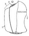
- FIGS. 1-3shows a conventional bubble generating machine 100.
- FIG. 1is a side view
- FIG. 2is a side sectional view
- FIG. 3is a top sectional view of the same conventional bubble machine.
- This bubble generating machine 100mainly comprises an outer cover or shell 101, a motor 102, a gear box 103, an impeller 104, a wheel 105, and a bubble solution reservoir 106.
- the shell 101includes an opening 107 for releasing the bubbles generated by the machine.
- the motor 102is positioned between the impeller 104 and the wheel 105, and functions to rotate the impeller 104 to produce airflow in a generally horizontal direction.
- the motor 102together with the gear box 103, also functions to rotate the bubble generating wheel 105.
- the wheelcomprises a plurality of rings 108 fixed to the rim of the wheel 105. When rotated, the rings 108 on the wheel 105 are sequentially dipped into the reservoir 106 that holds the bubble producing fluid (such as a dilute soap solution) and then removed therefrom as the wheel 105 continues rotating.
- the bubble solutionforms a thin film or membrane on the rings 108.
- the impeller 104blows air horizontally against the film, forming bubbles that are then released via the opening 107.
- the ringshave stria or teeth, allowing them to hold more fluid and thus make many more bubbles before the fluid needs to be replenished.
- bubble generating machineis often placed on a horizontal surface during use, but blowing bubbles in a horizontal direction causes a significant numbers of bubbles to burst on the horizontal surface, thus wasting a significant amount of bubble fluid.
- burst bubblesalso contaminate the surface area surrounding the bubble generating machine as well as the machine itself, necessitating subsequent cleaning of these surfaces. Further, the horizontal airflow results in less air time for each bubble, as each bubble is closer to the ground on release.
- Blowing bubbles in a vertical directionis generally not possible with these systems, as the bubble heads must be rotated through a horizontal reservoir of bubble solution and consequently must be orthogonal, or at a right angle, to such bubble solution. Tilting the machine as a whole into an upright direction would generally spill the bubble solution out of the reservoir, thereby eliminating the source of bubble solution for future bubbles from the bubble machine.
- the rotation of wheel 105is generally achieved by engaging the gear box 103 with the teeth located on the outer edge of wheel 105.
- the rotating plane of wheel 105is substantially in-line or parallel to the rotating axis of the motor 102. Consequently, the horizontal length of the traditional bubble generating machine needs to be long enough to accommodate the length of the impeller and the motor and gearbox, plus the entire diameter of the wheel 105, making the physical size of the bubble generating machine 100 quite large.
- the airflow produced by the impellor 104needs to travel from the impellor 104 through the area that accommodates the motor 102 and the gear box 103 before it reaches the wheel 105.
- the motor 102 and the gear box 103partially block the airflow produced by the impeller 104. This makes the conventional machine 100 less efficient at producing bubbles.
- US 4,133,138discloses a bubble forming and projecting device having an apertured bubble forming ring mounted in a chamber to rotate around a horizontal axis.
- An impelleris mounted within the ring to rotate about a vertical axis to generate an upward air current for projecting bubbles.
- the present inventionreverses the configuration of the motor and fan and turns the bubble wheel at right angles to significantly reduce the size of the bubble machine.
- the configurationis fan > motor > wheel
- the plane of the bubble wheelis in-line with the axis or plane of the fan and motor.
- a bubble generating machinecomprising: a housing having an opening; a bubble generator positioned inside the housing and adjacent to the opening, the bubble generator comprising a ring turntable and a turntable rotator attached to the ring turntable; a reservoir that contains a solution into which the bubble generator is partially immersed; an impeller positioned inside the housing; and a motor positioned inside the housing and operatively coupled to the impeller and the turntable rotator of the bubble generator, wherein the motor when actuated causes the impeller and the turntable rotator to rotate simultaneously; wherein the impeller is positioned between the bubble generator and the motor, and the turntable rotator, when driven by the motor, operates to rotate the ring turntable via a friction force.
- the actuated motorcauses the impeller and the bubble generator to rotate simultaneously.
- the impelleris positioned between the bubble generator and the motor. In some other embodiments, the impeller and the bubble generator share a common rotating axis.
- the bubble generating machinemay further comprise an airflow channel extending from the impeller towards the upper opening so as to force the airflow generated by the impeller from a horizontal direction to a substantially vertical direction.
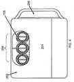
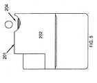
- FIGS. 4-6illustrate the exterior appearance of a bubble generating machine 200 according to one aspect of the present invention.
- FIG. 4is a top view of a bubble generating machine 200 according to a preferred embodiment of the present invention.
- FIG. 5is a side view and
- FIG. 6is a bottom view of the bubble generating machine 200 of FIG. 4 .
- the machine 200has a housing that comprises of a top surface 201, a side surface 202 and a bottom surface 203.
- the surfacescan be in a cubic or hemispherical shape, or any other desired shape.
- the various surfacesare connected together by, for example, screws or welding or glue, or alternatively the shell can be integral.
- These surfaces 201, 202 and 203together define a hollow interior for housing and protecting the internal components of the machine 200, as described below.
- FIGS. 4 and 5there is an opening 204 in the top surface 201, through which the rings can be seen and the bubbles released.
- the opening 204can be positioned on a top portion of a side surface 202.
- the opening 204is positioned at a top corner of the bubble generating machine 200, i.e. at the juncture of the top surface 201 and the side surface 202 or on an upper end of a side surface 202. In this way, bubbles will be blown out directly from the air channel below and will be propelled in a direction that is substantially away from the horizontal surface.
- the bubblesare emitted from an angle that is at least 10 degrees in reference to the horizontal surface.
- the bubblesare propelled vertically, e.g., about 90 degrees plus or minus 45 degrees, from the horizontal surface, as this is the most desired direction and allow the bubbles to stay in the air for the longest time before they reach the ground.
- the bubbleare essentially vertically (about 90 degrees) propelled.
- the location of the opening 204can also be used in the bubble generating machine 200.
- the bubble generating machineshould be considered as not departing from the teaching of the present invention.
- the reservoiris separate and is inserted into the housing from a side opening which may be closable if desired.
- the reservoiris defined by the bottom surface 203 and a lower part of the side surface 202.
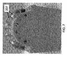
- the housingalso has an air inlet 207 (as shown in FIG. 7 ) which, in combination with the top opening 204, forms a complete path of the airflow driven by the impeller in the housing.
- the housinghas a bottom cover 205 in the bottom surface 203.
- the bottom cover 205seals the power source (not shown in FIGS. 4-6 ) for providing power to the motor in the housing.
- the bottom cover 205is attached to the housing with a screw.
- the power sourceis a set of batteries in some embodiments.
- an on/off switch 208is provided on the housing and preferably on the side surface 202 (as shown in FIG. 8 ).
- the switch 208in combination with other necessary electronic circuits, is operatively coupled to the power source for providing power to the motor in the housing.
- the necessary electronic circuitsare common knowledge in the related arts, description of which is therefore omitted herein for simplicity.
- FIGS. 9-11illustrate the internal structures of a bubble generating machine 300 according to some embodiments of the present invention.
- FIG. 9is a top sectional view of a bubble generating machine 300 according to a preferred embodiment of the present invention.
- FIG. 10is a side sectional view and
- FIG. 11is a rear sectional view of the bubble generating machine 300 of FIG. 9 .
- the bubble generating machine 300comprises a housing 301, a ring turntable 302, an impeller or fan 303, a motor 304, a gear box 305, and an airflow channel 306.
- the housing 301accommodates the other components of the bubble generator 300 and bubble solution in the reservoir of the housing 301 (not visible in FIG. 9 ).
- the ring turntable 302consists of a series of rings 309 positioned in a circular direction.
- the ringscan be of the same shape and diameter and, more preferably, in different diameters so as to produce bubbles of different sizes.
- the impeller 303may have a plurality of blades that are spaced apart around a hub.
- the impeller 303is operatively coupled to the motor 304.
- the impeller 303is driven by the motor 304 to rotate, producing substantially horizontal airflow to the air channel 306.
- the impeller 303is a fan.
- a motoris included in the bubble generating machine 300.
- the motor 304is operatively coupled to the impeller 303 on one side and to a gear box 305 on the other side, which in turn operates the ring turntable 302 via structures to be discussed below.
- the motor 304functions as the main source of generating motion to rotate the impellor 303 and the ring turntable 302.
- the motor 304is further electrically coupled to a power source via a switch and other necessary circuits. By operating the switch, the motor can be turned on/off.
- the gear box 305consists of a set of gears for rotating the ring turntable 302.
- the gear box 305is coupled to the motor 304 on one side and to the ring turntable 302 on the other side.
- a main shaft 308can be used to connect the motor 305 and the gear box.
- the set of gears in the gear box 305can be configured in such a manner that, when the motor 304 is actuated, the gear box 305 will rotate the ring turntable 302 at a rotating velocity that is slower than that of the impeller 303.
- This particular arrangementcan allow the motor 304 to serve two functions: 1) it rotates at a higher speed for rotating the impeller 303 and thus generating enough airflow to form bubbles; 2) it turns the gear box 305, which in turn, rotates the ring turntable 302, at a lower speed to allow the rings to slowly move through the airflow, thus allowing bubbles to form when the air blows through the rings 309.
- the lower rotating speedis achieved by varying the gear ratio of the different gears inside the gear box 305.
- Other structures/arrangementscan be used to achieve the same function as people skilled in the art can readily perceive, which will not be further elaborated herein for simplicity.
- an airflow channel 306is positioned between the impeller 303 and the rings 309 that rotates toward the opening 307.
- the air flow channel 306sits just beyond the impeller 303, and inside the turntable 302, thus accepting air from the impeller 303 and re-directing it into an upwards flow by virtue of its shape and top opening (not seen in Fig 9 , but see opening 407 in FIG. 12 , wherein opening 407 of the air channel 306/406 at least partially overlaps with opening 307 to ensure that air is efficiently blown out from opening 307).
- the airflow channel 306can be of various shapes.
- the airflow channelcan be an L shaped channel that directs the airflow generated by the impellor 303 from a horizontal direction to a substantially vertical direction toward the opening 307.
- different shaped airflow channelscan be used. The only requirement is that the airflow channel contain and redirect the airflow towards the opening in the exterior housing (thus the airflow channel opening and the housing opening largely overlap).
- the air flow channel 306can be cylindrical. Alternatively, the shape of the airflow channel 306 can be adapted to suit the contour of the impeller 303 motion. In yet another embodiment of the invention, the inner diameter of the airflow channel 306 is larger than that of the ring turntable 302. The airflow guided by the airflow channel 306 finally blows against the rings 309 of the ring turntable 302 and pushes the bubbles through the top opening 307 to the outside.
- the bubble generating machine 300 of the present inventionhas a more compact structure.
- the ring turntable 302rotates in a plane that is substantially vertical to the common rotating axis I-I' of motor 304.
- the motor 304, the impeller 303, and the ring turntable 302 in the preferred embodimentall share a common rotating axis I-I'.
- Such "common axis" structuremake the bubble generating machine 300 more compact than the conventional bubble generating machine 100 as shown in FIG. 1 , because the length of the bubble machine now accommodates the thickness of the ring turntable 302, not the diameter of the ring turntable 302.
- the size of the bubble generating machine 300can be greatly reduced.
- impeller 303 and/or motor 304can overlap with one another in terms of their spatial locations.
- impeller 303is positioned partially inside the circular space defined by the ring turntable 302.
- Other arrangementsare also possible.
- the motor 304may have a rotating axis I-I' (not shown)
- the impeller 303may have a different rotating axis A-A' (not shown)
- the ring turntable 302may have another rotating axis B-B' (not shown).
- the 3 axesare offset from each other and meanwhile remain substantially parallel to each other. In some other examples, angles of about 5 degrees, 5 degrees, 10 degrees, 15 degrees, 20 degrees, 25 degrees, 30 degrees, 35 degrees, 40 degrees, 45 degrees, and so on may exist between any two of the axes.
- the offset(s) and angle(s)can be achieved by using different gear box arrangement and/or rotating shaft(s) connecting the motor 304, the impeller 303, and the ring turntable 302.
- gear box arrangement and/or rotating shaft(s) connecting the motor 304, the impeller 303, and the ring turntable 302.As a person skilled in the art will understand, the above “substantially parallel” variations are also within the “common axis" limitations as defined in the appended claims.
- FIG. 12is an exploded view of the bubble generating machine 400 according to a preferred embodiment of the present invention.
- the airflow channel 406, the impellor 403, the motor 404, the gear box 405, and the ring turntable 402 of FIG. 12correspond to the airflow channel 306, the impellor 303, the motor 304, the gear box 305, and the ring turntable 302 of FIGS. 9-11 respectively.
- the bubble generating machine 400further comprises a connecting junction 4010 and a turntable rotator 4011.
- the connecting junction 4010is positioned between the airflow channel 406 and the turntable rotator 4011, and consists of a housing 4012 that holds the motor 404.
- the motor 404has a shaft 308 connecting to the gear box 405, which has an output gear that connects to an inline gear (not shown in the Figure) of the turntable rotator 4011.
- the motor 404When the motor 404 is actuated, the motor 404 will finally rotate the turntable rotator 4011 through the output gear of the gear box 405 and the inline gear of the turntable rotator 4011.
- connection between the connecting junction 4010 and the airflow channel 406is by screws or other means to fix the connecting junction 4010 to the air flow channel 406.
- the connecting junction 4010is not physically connected to the turntable rotator 4011. They are actually two separate parts adjacent to each other.
- the turntable rotator 4011is not fixed to the ring turntable 402. Instead, it is positioned closely adjacent to the ring turntable 402 so that the rotation of the turntable rotator 4011 will force and turn the ring turntable 402 attached to it via friction force.
- the turntable rotator 4011comprises a connecting rim 4013 in annular shape, that matches well with the inner rim 4014 of the ring turntable 402, i.e., closely opposed to each other.
- the connecting rim 4013 of the turntable rotator 4011will exert friction force on the inner rim 4014 of the ring turntable 402, and cause the ring turntable 402 to rotate accordingly.
- the novel "attaching" structure of the present inventionfunctions as a safety mechanism. For example, when a person such as a child accidentally puts a finger or a pencil into the bubble blower hole, the ring turntable 402 will stop rotating. If the turntable rotator 4011 were fixed to the ring turntable 402, the turntable 402 would not be easily stopped, which may cause injuries to the child. Also, if the turntable 402 were forced to stop, it would in turn force the gear box 405 and the motor 404 to stop, which could cause overheating to the motor 404 and/or stripping of the gears.
- the gear box 405, the motor 404 and a portion of the connection junction 4010are located within the cylindrical hollow portion of the turntable rotator 4011.
- the air channel 406 together with another portion of the connection junction 4010forms a winding drum for guiding the airflow generated by the impeller 403.
- the novel bubble generating machine of the present inventionhas several advantages over the conventional bubble generating machine as shown in FIGS. 1-3 .
- the bubble generating machine according to one embodiment of the present inventionhas a reduced size because the motor, the impeller and the ring turntable share a common, or substantially common, rotating axis.
- the impeller of the bubble generating machine of the inventionis positioned between the ring turntable and the motor.
- the airflow generated by the impellerdirectly blows against the blower turntable, whereas the motor of the conventional bubble generating machine will block some of the airflow generated by the impeller.
- the more sufficient usage of the airflow in the present inventionwill increase the productivity of the bubbles generated.
- the efficient use of the airflowmakes it possible to use smaller impeller, smaller winding drum and smaller motor, which further reduces the size of the bubble generating machine.
- a compact size bubble generating machine(e.g., bubble generating machine 300) of the present invention provides can simultaneously actuate the rotation of the air generator (e.g., impeller 303) and the bubble generator (e.g., ring turntable 302) at different rotating velocities. Also, with the air channel 306 or 406, the bubble generating machine of the present invention can produce bubbles in a substantially vertical direction, thus giving longer bubble air time. Additionally, according to one embodiment of the present invention, the structure of the bubble generating machine that the turntable rotator is attached but not fixed to the ring turntable provides a safety mechanism that prevents the motor from overheating when the ring turntable is forcibly stopped.
- the air channel and the connection junctionmay be combine together to be a single components and a separate container containing bubble solution may be placed in or attached to the bubble generating machine instead of the self-reservoir formed by the housing of the bubble generating machine.
Landscapes
- Toys (AREA)
- Percussion Or Vibration Massage (AREA)
Abstract
Description
- The present invention relates to bubble generating toys, and in particular, to a compact size bubble generating machine that generates continuous streams of bubbles in desired directions.
- Bubble generating machines have many adaptations and uses and are particularly appealing to young children. Many bubble generating machines are already available on the market. For example,
FIGS. 1-3 shows a conventional bubble generating machine 100. Specifically,FIG. 1 is a side view,FIG. 2 is a side sectional view, andFIG. 3 is a top sectional view of the same conventional bubble machine. - This bubble generating machine 100 mainly comprises an outer cover or
shell 101, amotor 102, agear box 103, animpeller 104, awheel 105, and abubble solution reservoir 106. Theshell 101 includes anopening 107 for releasing the bubbles generated by the machine. - The
motor 102 is positioned between theimpeller 104 and thewheel 105, and functions to rotate theimpeller 104 to produce airflow in a generally horizontal direction. Themotor 102, together with thegear box 103, also functions to rotate the bubble generatingwheel 105. The wheel comprises a plurality ofrings 108 fixed to the rim of thewheel 105. When rotated, therings 108 on thewheel 105 are sequentially dipped into thereservoir 106 that holds the bubble producing fluid (such as a dilute soap solution) and then removed therefrom as thewheel 105 continues rotating. The bubble solution forms a thin film or membrane on therings 108. Theimpeller 104 blows air horizontally against the film, forming bubbles that are then released via theopening 107. Generally, the rings have stria or teeth, allowing them to hold more fluid and thus make many more bubbles before the fluid needs to be replenished. - However, it is generally undesirable to blow bubbles in the horizontal direction for several reasons. For example, the bubble generating machine is often placed on a horizontal surface during use, but blowing bubbles in a horizontal direction causes a significant numbers of bubbles to burst on the horizontal surface, thus wasting a significant amount of bubble fluid.
- The burst bubbles also contaminate the surface area surrounding the bubble generating machine as well as the machine itself, necessitating subsequent cleaning of these surfaces. Further, the horizontal airflow results in less air time for each bubble, as each bubble is closer to the ground on release.
- Blowing bubbles in a vertical direction is generally not possible with these systems, as the bubble heads must be rotated through a horizontal reservoir of bubble solution and consequently must be orthogonal, or at a right angle, to such bubble solution. Tilting the machine as a whole into an upright direction would generally spill the bubble solution out of the reservoir, thereby eliminating the source of bubble solution for future bubbles from the bubble machine.
- Further, the rotation of
wheel 105 is generally achieved by engaging thegear box 103 with the teeth located on the outer edge ofwheel 105. The rotating plane ofwheel 105 is substantially in-line or parallel to the rotating axis of themotor 102. Consequently, the horizontal length of the traditional bubble generating machine needs to be long enough to accommodate the length of the impeller and the motor and gearbox, plus the entire diameter of thewheel 105, making the physical size of the bubble generating machine 100 quite large. - Moreover, the airflow produced by the
impellor 104 needs to travel from theimpellor 104 through the area that accommodates themotor 102 and thegear box 103 before it reaches thewheel 105. Themotor 102 and thegear box 103 partially block the airflow produced by theimpeller 104. This makes the conventional machine 100 less efficient at producing bubbles. - Therefore, there is a need for a compact size bubble generating machine that automatically generates a continuous stream of bubbles in a substantially vertical direction and in a more efficient way.
US 4,133,138 discloses a bubble forming and projecting device having an apertured bubble forming ring mounted in a chamber to rotate around a horizontal axis. An impeller is mounted within the ring to rotate about a vertical axis to generate an upward air current for projecting bubbles.- The present invention reverses the configuration of the motor and fan and turns the bubble wheel at right angles to significantly reduce the size of the bubble machine. In the prior art machine above, the configuration is fan > motor > wheel, and the plane of the bubble wheel is in-line with the axis or plane of the fan and motor. By putting the wheel at right angles, and/or by reversing the motor and fan configuration (motor > fan > wheel), and/or by sitting the fan wholly or partially inside the wheel, the current invention significantly reduces the footprint of the device.
- According to the invention, there is provided a bubble generating machine comprising: a housing having an opening; a bubble generator positioned inside the housing and adjacent to the opening, the bubble generator comprising a ring turntable and a turntable rotator attached to the ring turntable; a reservoir that contains a solution into which the bubble generator is partially immersed; an impeller positioned inside the housing; and a motor positioned inside the housing and operatively coupled to the impeller and the turntable rotator of the bubble generator, wherein the motor when actuated causes the impeller and the turntable rotator to rotate simultaneously; wherein the impeller is positioned between the bubble generator and the motor, and the turntable rotator, when driven by the motor, operates to rotate the ring turntable via a friction force.
- In the invention, the actuated motor causes the impeller and the bubble generator to rotate simultaneously. In some embodiments, the impeller is positioned between the bubble generator and the motor. In some other embodiments, the impeller and the bubble generator share a common rotating axis.
- In some embodiments, the bubble generating machine may further comprise an airflow channel extending from the impeller towards the upper opening so as to force the airflow generated by the impeller from a horizontal direction to a substantially vertical direction.
- Other aspects of the invention are set out in the accompanying claims.
- The following detailed description and the accompanying drawings further illustrate certain embodiments of the current invention.
- In the drawings:
FIG. 1 is a side view of a conventional bubble generating machine;FIG. 2 is a side sectional view of the conventional bubble generating machine ofFIG. 1 ;FIG. 3 is a top sectional view of the conventional bubble generating machine ofFIG. 1 ;FIG. 4 is a top view of a bubble generating machine according to some embodiments of the present invention;FIG. 5 is a side view of the bubble generating machine ofFIG. 4 ;FIG. 6 is a bottom view of the bubble generating machine ofFIG. 4 ;FIG. 7 shows a side surface of a bubble generating machine having an air inlet according to one embodiment of the present invention;FIG. 8 shows a side surface of a bubble generating machine having a switch according to one embodiment of the present invention;FIG. 9 is a top sectional view of a bubble generating machine according to some further embodiments of the present invention;FIG. 10 is a side sectional view of the bubble generating machine ofFIG. 9 ;FIG. 11 is a rear sectional view of the bubble generating machine ofFIG. 9 ;FIG. 12 is an exploded view of the bubble generating machine according to some embodiments of the present invention; andFIG. 13 shows an "attaching" structure between the turntable rotator and the ring turntable of a bubble generating machine according to one embodiment of this invention.- The following detailed description is directed to various embodiments of the invention. It is made for the purpose of illustrating different embodiments of the invention, and should not be taken as limitations to the current invention. The scope of the invention is defined by the appended claims. In certain instances, detailed descriptions of well-known devices and mechanisms are omitted so as to not obscure the description of the present invention with unnecessary detail.
FIGS. 4-6 illustrate the exterior appearance of a bubble generating machine 200 according to one aspect of the present invention. Specifically,FIG. 4 is a top view of a bubble generating machine 200 according to a preferred embodiment of the present invention.FIG. 5 is a side view andFIG. 6 is a bottom view of the bubble generating machine 200 ofFIG. 4 . As shown inFIG. 4-6 , the machine 200 has a housing that comprises of atop surface 201, aside surface 202 and abottom surface 203. The surfaces can be in a cubic or hemispherical shape, or any other desired shape. The various surfaces are connected together by, for example, screws or welding or glue, or alternatively the shell can be integral. Thesesurfaces - Referring to
FIGS. 4 and5 , in some embodiments of the invention, there is anopening 204 in thetop surface 201, through which the rings can be seen and the bubbles released. - Alternatively, the
opening 204 can be positioned on a top portion of aside surface 202. In some other embodiments, theopening 204 is positioned at a top corner of the bubble generating machine 200, i.e. at the juncture of thetop surface 201 and theside surface 202 or on an upper end of aside surface 202. In this way, bubbles will be blown out directly from the air channel below and will be propelled in a direction that is substantially away from the horizontal surface. - By "substantially away from the horizontal surface" what is meant herein is that the bubbles are emitted from an angle that is at least 10 degrees in reference to the horizontal surface. In a preferred embodiment, the bubbles are propelled vertically, e.g., about 90 degrees plus or minus 45 degrees, from the horizontal surface, as this is the most desired direction and allow the bubbles to stay in the air for the longest time before they reach the ground. In the most preferred embodiment, the bubble are essentially vertically (about 90 degrees) propelled.
- As people in the art can readily perceive, other variations of the location of the
opening 204 can also be used in the bubble generating machine 200. As long as the bubbles are blown from a substantially vertical direction away from the horizontal surface as shown in the conventional bubble generating machine 100 ofFIGS. 1-3 , the bubble generating machine should be considered as not departing from the teaching of the present invention. - In some embodiments of the invention, there is a
port 206 in theside surface 202 for adding bubble solution to the reservoir (not shown inFIGS. 4-6 ) located at the bottom of the housing. In other embodiments, the reservoir is separate and is inserted into the housing from a side opening which may be closable if desired. In other embodiments of the invention, the reservoir is defined by thebottom surface 203 and a lower part of theside surface 202. In yet some other embodiments of the invention, the housing also has an air inlet 207 (as shown inFIG. 7 ) which, in combination with thetop opening 204, forms a complete path of the airflow driven by the impeller in the housing. - Referring to
FIG. 6 , the housing has abottom cover 205 in thebottom surface 203. Thebottom cover 205 seals the power source (not shown inFIGS. 4-6 ) for providing power to the motor in the housing. In some embodiments of the invention, thebottom cover 205 is attached to the housing with a screw. The power source is a set of batteries in some embodiments. - In another embodiment of the invention, an on/off
switch 208 is provided on the housing and preferably on the side surface 202 (as shown inFIG. 8 ). Theswitch 208, in combination with other necessary electronic circuits, is operatively coupled to the power source for providing power to the motor in the housing. The necessary electronic circuits are common knowledge in the related arts, description of which is therefore omitted herein for simplicity. FIGS. 9-11 illustrate the internal structures of a bubble generating machine 300 according to some embodiments of the present invention. Specifically,FIG. 9 is a top sectional view of a bubble generating machine 300 according to a preferred embodiment of the present invention.FIG. 10 is a side sectional view andFIG. 11 is a rear sectional view of the bubble generating machine 300 ofFIG. 9 .- Referring to
FIG. 9 , the bubble generating machine 300 comprises ahousing 301, aring turntable 302, an impeller orfan 303, amotor 304, agear box 305, and anairflow channel 306. As shown inFIG. 9 , thehousing 301 accommodates the other components of the bubble generator 300 and bubble solution in the reservoir of the housing 301 (not visible inFIG. 9 ). - The
ring turntable 302 consists of a series ofrings 309 positioned in a circular direction. We have shown the rings as toothed or serrated annular forms, but any shape can be used, so long as it will hold some amount of fluid and create a membrane through which bubbles can be blown. Further, therings 309 can be of the same shape and diameter and, more preferably, in different diameters so as to produce bubbles of different sizes. When thering turntable 302 rotates, therings 309 on the turntable sequentially dip into the bubble solution to form solution films, and then sequentially pass through the opening of theairflow channel 306 to generate bubbles. The bubbles are released to the air through thetop opening 307 of thehousing 301 in a substantially vertical direction due to the fact that theair channel 306 forces air into a vertical flow. - As shown in
FIG. 9 , theimpeller 303 may have a plurality of blades that are spaced apart around a hub. Theimpeller 303 is operatively coupled to themotor 304. When themotor 304 is actuated, theimpeller 303 is driven by themotor 304 to rotate, producing substantially horizontal airflow to theair channel 306. In one embodiment of the invention, theimpeller 303 is a fan. - To propel the
impeller 303 and thering turntable 302, a motor is included in the bubble generating machine 300. Preferably, only onemotor 304 is used in the entire bubble generating machine, which will be discussed in more detail below. However, people skilled in the art would appreciate that more than one motor can be used to achieve the same effects as described herein. - In some embodiments, the
motor 304 is operatively coupled to theimpeller 303 on one side and to agear box 305 on the other side, which in turn operates thering turntable 302 via structures to be discussed below. Themotor 304 functions as the main source of generating motion to rotate theimpellor 303 and thering turntable 302. In one embodiment, themotor 304 is further electrically coupled to a power source via a switch and other necessary circuits. By operating the switch, the motor can be turned on/off. - Preferably, the
gear box 305 consists of a set of gears for rotating thering turntable 302. In some embodiments, thegear box 305 is coupled to themotor 304 on one side and to thering turntable 302 on the other side. Amain shaft 308 can be used to connect themotor 305 and the gear box. The set of gears in thegear box 305 can be configured in such a manner that, when themotor 304 is actuated, thegear box 305 will rotate thering turntable 302 at a rotating velocity that is slower than that of theimpeller 303. This particular arrangement can allow themotor 304 to serve two functions: 1) it rotates at a higher speed for rotating theimpeller 303 and thus generating enough airflow to form bubbles; 2) it turns thegear box 305, which in turn, rotates thering turntable 302, at a lower speed to allow the rings to slowly move through the airflow, thus allowing bubbles to form when the air blows through therings 309. In some embodiments, the lower rotating speed is achieved by varying the gear ratio of the different gears inside thegear box 305. Other structures/arrangements can be used to achieve the same function as people skilled in the art can readily perceive, which will not be further elaborated herein for simplicity. - In some embodiments, an
airflow channel 306 is positioned between theimpeller 303 and therings 309 that rotates toward theopening 307. In other words, theair flow channel 306 sits just beyond theimpeller 303, and inside theturntable 302, thus accepting air from theimpeller 303 and re-directing it into an upwards flow by virtue of its shape and top opening (not seen inFig 9 , but see opening 407 inFIG. 12 , wherein opening 407 of theair channel 306/406 at least partially overlaps with opening 307 to ensure that air is efficiently blown out from opening 307). - Depending on the location of the
opening 307 on the surface of the bubble generating machine, theairflow channel 306 can be of various shapes. For example, when theopening 307 is positioned on the top surface of the bubble generating machine, the airflow channel can be an L shaped channel that directs the airflow generated by theimpellor 303 from a horizontal direction to a substantially vertical direction toward theopening 307. In other embodiments, when theopening 307 is position at another portion of the bubble machine's surfaces, different shaped airflow channels can be used. The only requirement is that the airflow channel contain and redirect the airflow towards the opening in the exterior housing (thus the airflow channel opening and the housing opening largely overlap). - The
air flow channel 306 can be cylindrical. Alternatively, the shape of theairflow channel 306 can be adapted to suit the contour of theimpeller 303 motion. In yet another embodiment of the invention, the inner diameter of theairflow channel 306 is larger than that of thering turntable 302. The airflow guided by theairflow channel 306 finally blows against therings 309 of thering turntable 302 and pushes the bubbles through thetop opening 307 to the outside. - In contrast to the conventional bubble generating machine 100 as shown in
FIGS. 1-3 , the bubble generating machine 300 of the present invention has a more compact structure. As shown inFIGS. 9-10 , in one embodiment of the current invention, thering turntable 302 rotates in a plane that is substantially vertical to the common rotating axis I-I' ofmotor 304. Stated in another way, themotor 304, theimpeller 303, and thering turntable 302 in the preferred embodiment all share a common rotating axis I-I'. Such "common axis" structure make the bubble generating machine 300 more compact than the conventional bubble generating machine 100 as shown inFIG. 1 , because the length of the bubble machine now accommodates the thickness of thering turntable 302, not the diameter of thering turntable 302. Thus, the size of the bubble generating machine 300 can be greatly reduced. - To further reduce the size of the bubble generating machine 300, certain portions of the
turntable 302,impeller 303 and/ormotor 304 can overlap with one another in terms of their spatial locations. For example, as shown inFIG. 9 ,impeller 303 is positioned partially inside the circular space defined by thering turntable 302. Other arrangements are also possible. - It should be noted that variations to the above described common rotating axis I-I' can also be used without departing from the teaching of the current invention. For example, the
motor 304 may have a rotating axis I-I' (not shown), theimpeller 303 may have a different rotating axis A-A' (not shown), thering turntable 302 may have another rotating axis B-B' (not shown). The 3 axes are offset from each other and meanwhile remain substantially parallel to each other. In some other examples, angles of about 5 degrees, 5 degrees, 10 degrees, 15 degrees, 20 degrees, 25 degrees, 30 degrees, 35 degrees, 40 degrees, 45 degrees, and so on may exist between any two of the axes. The offset(s) and angle(s) can be achieved by using different gear box arrangement and/or rotating shaft(s) connecting themotor 304, theimpeller 303, and thering turntable 302. As a person skilled in the art will understand, the above "substantially parallel" variations are also within the "common axis" limitations as defined in the appended claims. - Refer to
FIG. 12 for a more detailed illustration of the "common axis" structure depicted inFIGS. 9-11 .FIG. 12 is an exploded view of the bubble generating machine 400 according to a preferred embodiment of the present invention. According toFIG. 12 , theairflow channel 406, theimpellor 403, themotor 404, thegear box 405, and thering turntable 402 ofFIG. 12 correspond to theairflow channel 306, theimpellor 303, themotor 304, thegear box 305, and thering turntable 302 ofFIGS. 9-11 respectively. In a preferred embodiment of the present invention, the bubble generating machine 400 further comprises a connectingjunction 4010 and aturntable rotator 4011. - The connecting
junction 4010 is positioned between theairflow channel 406 and theturntable rotator 4011, and consists of ahousing 4012 that holds themotor 404. As shown inFIGS. 9-12 , according to one embodiment of the invention, themotor 404 has ashaft 308 connecting to thegear box 405, which has an output gear that connects to an inline gear (not shown in the Figure) of theturntable rotator 4011. When themotor 404 is actuated, themotor 404 will finally rotate theturntable rotator 4011 through the output gear of thegear box 405 and the inline gear of theturntable rotator 4011. - According to one embodiment of this invention, the connection between the connecting
junction 4010 and theairflow channel 406 is by screws or other means to fix the connectingjunction 4010 to theair flow channel 406. On the other hand, the connectingjunction 4010 is not physically connected to theturntable rotator 4011. They are actually two separate parts adjacent to each other. - In a preferred embodiment, the
turntable rotator 4011 is not fixed to thering turntable 402. Instead, it is positioned closely adjacent to thering turntable 402 so that the rotation of theturntable rotator 4011 will force and turn thering turntable 402 attached to it via friction force. According to one embodiment of this invention as shown inFIG. 13 , theturntable rotator 4011 comprises a connectingrim 4013 in annular shape, that matches well with theinner rim 4014 of thering turntable 402, i.e., closely opposed to each other. When theturntable rotator 4011 is rotated by themotor 404, the connectingrim 4013 of theturntable rotator 4011 will exert friction force on theinner rim 4014 of thering turntable 402, and cause thering turntable 402 to rotate accordingly. - In comparison with the traditional structure that the motor is fixed to the
ring turntable 406, either directly or via a gear box/turntable rotator, the novel "attaching" structure of the present invention functions as a safety mechanism. For example, when a person such as a child accidentally puts a finger or a pencil into the bubble blower hole, thering turntable 402 will stop rotating. If theturntable rotator 4011 were fixed to thering turntable 402, theturntable 402 would not be easily stopped, which may cause injuries to the child. Also, if theturntable 402 were forced to stop, it would in turn force thegear box 405 and themotor 404 to stop, which could cause overheating to themotor 404 and/or stripping of the gears. In the above "attaching" design, such problem is avoid as theturntable rotator 4011 is only attached to thering turntable 402 via friction and therefore, if thering turntable 402 is being stopped accidentally, theturntable rotator 4011 can rotate by itself and thus prevent injuries to the operator and/or overheating to themotor 404. - When the various components in
FIG. 12 are assembled together, thegear box 405, themotor 404 and a portion of theconnection junction 4010 are located within the cylindrical hollow portion of theturntable rotator 4011. Theair channel 406 together with another portion of theconnection junction 4010 forms a winding drum for guiding the airflow generated by theimpeller 403. - The novel bubble generating machine of the present invention has several advantages over the conventional bubble generating machine as shown in
FIGS. 1-3 . First, as described above, the bubble generating machine according to one embodiment of the present invention has a reduced size because the motor, the impeller and the ring turntable share a common, or substantially common, rotating axis. Second, unlike the conventional bubble generating machine, the impeller of the bubble generating machine of the invention is positioned between the ring turntable and the motor. Thus the airflow generated by the impeller directly blows against the blower turntable, whereas the motor of the conventional bubble generating machine will block some of the airflow generated by the impeller. The more sufficient usage of the airflow in the present invention will increase the productivity of the bubbles generated. Moreover, the efficient use of the airflow makes it possible to use smaller impeller, smaller winding drum and smaller motor, which further reduces the size of the bubble generating machine. - Further, a compact size bubble generating machine (e.g., bubble generating machine 300) of the present invention provides can simultaneously actuate the rotation of the air generator (e.g., impeller 303) and the bubble generator (e.g., ring turntable 302) at different rotating velocities. Also, with the
air channel - While the description above refers to particular embodiments of the present invention, it will be understood that modifications may be made without departing from the scope of the appended claims. For example, the air channel and the connection junction may be combine together to be a single components and a separate container containing bubble solution may be placed in or attached to the bubble generating machine instead of the self-reservoir formed by the housing of the bubble generating machine.
Claims (15)
- A bubble generating machine (200, 300, 400) comprising:a housing (301) having an opening (204, 307);a bubble generator positioned inside the housing (301) and adjacent to the opening (204), the bubble generator comprising a ring turntable (302, 402) and a turntable rotator (4011) attached to the ring turntable (302, 402);a reservoir that contains a solution into which the bubble generator is partially immersed;an impeller (303, 403) positioned inside the housing (301); anda motor (304, 404) positioned inside the housing (301) and operatively coupled to the impeller (303, 403) and the turntable rotator (4011) of the bubble generator, wherein the motor (304, 404) when actuated causes the impeller (303, 403) and the turntable rotator (4011) to rotate simultaneously;wherein the impeller (303, 403) is positioned between the bubble generator and the motor (304, 404), andcharacterised in that:the turntable rotator (4011), when driven by the motor (304, 404), operates to rotate the ring turntable (302, 402) via a friction force.
- A bubble generating machine according to claim 1, wherein the motor (304, 404), the impeller (303, 403) and the bubble generator share a common rotation axis.
- A bubble generating machine according to claim 1 or 2, further comprising an airflow channel (306, 406) extending from the impeller (303, 403) towards the opening (204, 307) and forcing the airflow generated by the impeller (303, 403) from a horizontal direction to a substantially vertical direction.
- A bubble generating machine according to claim 3, wherein the opening (204, 307) is on a top surface (201) of the housing (301).
- A bubble generating machine according to claim 3, wherein the opening (204, 307) is on an upper side surface (202) of the housing (301).
- A bubble generating machine according to any preceding claim comprising a gear system (305, 405) that couples the motor (304, 404) to the bubble generator, the gear system (305, 405) causing the bubble generator to rotate at a lower rotating velocity than the impeller (303, 403).
- A bubble generating machine according to claim 1, wherein the ring turntable (302, 402) comprises a series of annular rings (309).
- A bubble generating machine according to claim 7, wherein the series of rings (309) is arranged in a circular direction.
- A bubble generating machine according to any preceding claim, wherein the housing (301) comprises an air inlet (207) positioned on a side wall (202) of the housing (301).
- A bubble generating machine according to any preceding claim, wherein the impeller (303, 403) comprises a fan.
- A bubble generating machine according to claim 1, wherein
the ring turntable (302, 402) is positioned inside the housing (301) and adjacent to the opening (204, 307) and is partially immersed in a bubble solution contained in the reservoir;
the impeller (303, 403) is a fan positioned between the ring turntable (302, 402) and the motor (304, 404);
the motor (304, 404) is operatively coupled to the fan and the turntable rotator (4011) to rotate the fan and the turntable rotator (4011) simultaneously when actuated; and
the machine includes an airflow channel (306, 406) extending from the fan towards the opening (204, 307) and forcing the airflow generated by the fan from a substantially horizontal direction to a substantially vertical direction. - A bubble generating machine according to claim 11, wherein the motor (304, 404), the fan and the ring turntable (302, 402) share a common rotation axis.
- A bubble generating machine according to claim 11 or 12 comprising a gear box (305, 405) that couples the motor (304, 404) to the turntable rotator (4011), the gear box (305, 405) causing the turntable rotator (4011) to rotate at a lower rotating velocity than the fan.
- A bubble generating machine according to any preceding claim further comprising:a power source; anda switch (208) operatively coupled to the power source and the motor (304, 404) for actuating the motor (304, 404).
- A bubble generating machine according to any preceding claim, wherein the reservoir is defined by the bottom portion of the housing (301).
Applications Claiming Priority (1)
| Application Number | Priority Date | Filing Date | Title |
|---|---|---|---|
| US11/744,534US20080274662A1 (en) | 2007-05-04 | 2007-05-04 | Vertical bubble machine |
Publications (2)
| Publication Number | Publication Date |
|---|---|
| EP1987866A1 EP1987866A1 (en) | 2008-11-05 |
| EP1987866B1true EP1987866B1 (en) | 2010-08-18 |
Family
ID=39620403
Family Applications (1)
| Application Number | Title | Priority Date | Filing Date |
|---|---|---|---|
| EP08250717AActiveEP1987866B1 (en) | 2007-05-04 | 2008-03-03 | Bubble generating machine |
Country Status (5)
| Country | Link |
|---|---|
| US (1) | US20080274662A1 (en) |
| EP (1) | EP1987866B1 (en) |
| CN (2) | CN201249042Y (en) |
| AT (1) | ATE477840T1 (en) |
| DE (1) | DE602008002175D1 (en) |
Families Citing this family (16)
| Publication number | Priority date | Publication date | Assignee | Title |
|---|---|---|---|---|
| USD600289S1 (en)* | 2007-12-11 | 2009-09-15 | Wing Hing Manufacturing Co., Ltd. | Bubble machine |
| IL196973A (en)* | 2009-02-09 | 2012-05-31 | A M I Fun Ltd | Bathtub foam generating device |
| USD642629S1 (en) | 2010-07-02 | 2011-08-02 | Wing Hing Manufacturing Co. Ltd. | Bubble machine |
| USD643477S1 (en) | 2010-07-02 | 2011-08-16 | Wing Hing Manufacturing Co. Ltd. | Bubble machine |
| USD678421S1 (en)* | 2011-05-20 | 2013-03-19 | Hedeen International, Llc | Bubble generating vacuum toy |
| USD717880S1 (en)* | 2013-07-17 | 2014-11-18 | Bo Chen | Bubble maker toy |
| US11684868B2 (en) | 2013-11-08 | 2023-06-27 | Honor Metro Limited | Apparatus for generating bubbles |
| US9884262B2 (en)* | 2013-11-08 | 2018-02-06 | Honor Metro Limited | Bubble generating apparatus |
| US12172098B2 (en) | 2013-11-08 | 2024-12-24 | Honor Metro Limited | Apparatus for generating bubbles |
| CN108499138B (en) | 2014-03-20 | 2020-10-27 | 荣誉大都会有限公司 | Apparatus and method for generating bubbles |
| CN106267853A (en)* | 2015-06-09 | 2017-01-04 | 荣誉大都会有限公司 | For producing the device of bubble |
| USD790009S1 (en)* | 2016-04-07 | 2017-06-20 | Wing Hing Manufacturing Co. Ltd. | Bubble maker |
| CN108671564A (en)* | 2018-07-18 | 2018-10-19 | 广州市德珑舞台设备有限公司 | Durable type bubble generating machine |
| US10363492B1 (en)* | 2018-08-21 | 2019-07-30 | Placo Bubbles Limited | Bubble machine for producing vertical bubbles |
| USD896318S1 (en)* | 2019-04-30 | 2020-09-15 | Shenzhen Qianhai Junlian Network Technology Co. Ltd. | Bubble machine |
| US12161949B2 (en)* | 2022-08-05 | 2024-12-10 | Lizhen Lin | Bubble machine with adjustable blowing angle |
Family Cites Families (10)
| Publication number | Priority date | Publication date | Assignee | Title |
|---|---|---|---|---|
| US2984036A (en)* | 1959-12-07 | 1961-05-16 | Jr Joseph I Adler | Garland construction |
| US3100947A (en)* | 1960-12-29 | 1963-08-20 | Werner F Hellman | Toy for forming a continuous stream of bubbles |
| US3939581A (en)* | 1973-06-11 | 1976-02-24 | Clarke Jr Frank H | Organic molecular model assembly |
| US4133138A (en)* | 1977-03-17 | 1979-01-09 | Scott Coons | Bubble forming and projecting device |
| US5049105A (en)* | 1990-03-13 | 1991-09-17 | Magic Mold Corporation | Hub connector for tubes in toy construction set |
| US5238437A (en)* | 1992-02-07 | 1993-08-24 | Mattel, Inc. | Bubble dispensing doll |
| US6102764A (en)* | 1998-12-08 | 2000-08-15 | Placo Corporation Limited | Bubble generating assembly |
| US6820662B2 (en)* | 2001-12-20 | 2004-11-23 | Original Ideas | Vertical bubble dispensing device |
| USD490861S1 (en)* | 2003-09-24 | 2004-06-01 | Wilton Industries, Inc. | Bubble machine |
| US7144291B2 (en)* | 2004-09-08 | 2006-12-05 | Arko Development Limited | Bubble machine |
- 2007
- 2007-05-04USUS11/744,534patent/US20080274662A1/ennot_activeAbandoned
- 2008
- 2008-03-03DEDE602008002175Tpatent/DE602008002175D1/enactiveActive
- 2008-03-03EPEP08250717Apatent/EP1987866B1/enactiveActive
- 2008-03-03ATAT08250717Tpatent/ATE477840T1/ennot_activeIP Right Cessation
- 2008-04-30CNCNU2008201108009Upatent/CN201249042Y/ennot_activeExpired - Lifetime
- 2008-04-30CNCN2008100938223Apatent/CN101298000B/enactiveActive
Also Published As
| Publication number | Publication date |
|---|---|
| CN201249042Y (en) | 2009-06-03 |
| CN101298000B (en) | 2011-09-21 |
| DE602008002175D1 (en) | 2010-09-30 |
| ATE477840T1 (en) | 2010-09-15 |
| EP1987866A1 (en) | 2008-11-05 |
| CN101298000A (en) | 2008-11-05 |
| US20080274662A1 (en) | 2008-11-06 |
Similar Documents
| Publication | Publication Date | Title |
|---|---|---|
| EP1987866B1 (en) | Bubble generating machine | |
| US8272916B2 (en) | Bubble generating assembly that produces vertical bubbles | |
| US8272915B2 (en) | Bubble generating assembly that produces vertical bubbles | |
| US10363492B1 (en) | Bubble machine for producing vertical bubbles | |
| US7780497B2 (en) | Bubble machine | |
| US7144291B2 (en) | Bubble machine | |
| US10702787B2 (en) | Bubble machine for producing vertical bubbles | |
| US8038500B2 (en) | Bubble generating assembly | |
| EP4137218B1 (en) | Dual head continuous bubble blower | |
| US6102764A (en) | Bubble generating assembly | |
| CA2824412C (en) | Rotational bubble generating apparatus with non-spill reservoir | |
| US4775348A (en) | Bubble machine | |
| US4133138A (en) | Bubble forming and projecting device | |
| US6315627B1 (en) | Bubble generating assembly | |
| US10525371B1 (en) | Bladeless bubble fan | |
| US10717016B2 (en) | Assembly with inner object in housing that breaks out of housing | |
| CN102454645A (en) | Fan assembly | |
| US5269715A (en) | Soap bubble making apparatus | |
| US20060273612A1 (en) | Stroller with playing tool | |
| US10780365B2 (en) | Bubble generating apparatus | |
| JP2007021148A (en) | Water toy | |
| US12364371B2 (en) | Soap foam generating machine | |
| CN223009794U (en) | Hand-held type smog bubble system | |
| CN118987636A (en) | Handheld smoke bubble system and smoke bubble generation method | |
| JP2010158349A (en) | Soap bubble generator |
Legal Events
| Date | Code | Title | Description |
|---|---|---|---|
| PUAI | Public reference made under article 153(3) epc to a published international application that has entered the european phase | Free format text:ORIGINAL CODE: 0009012 | |
| AK | Designated contracting states | Kind code of ref document:A1 Designated state(s):AT BE BG CH CY CZ DE DK EE ES FI FR GB GR HR HU IE IS IT LI LT LU LV MC MT NL NO PL PT RO SE SI SK TR | |
| AX | Request for extension of the european patent | Extension state:AL BA MK RS | |
| 17P | Request for examination filed | Effective date:20090330 | |
| 17Q | First examination report despatched | Effective date:20090504 | |
| AKX | Designation fees paid | Designated state(s):AT BE BG CH CY CZ DE DK EE ES FI FR GB GR HR HU IE IS IT LI LT LU LV MC MT NL NO PL PT RO SE SI SK TR | |
| GRAP | Despatch of communication of intention to grant a patent | Free format text:ORIGINAL CODE: EPIDOSNIGR1 | |
| GRAS | Grant fee paid | Free format text:ORIGINAL CODE: EPIDOSNIGR3 | |
| GRAA | (expected) grant | Free format text:ORIGINAL CODE: 0009210 | |
| AK | Designated contracting states | Kind code of ref document:B1 Designated state(s):AT BE BG CH CY CZ DE DK EE ES FI FR GB GR HR HU IE IS IT LI LT LU LV MC MT NL NO PL PT RO SE SI SK TR | |
| REG | Reference to a national code | Ref country code:GB Ref legal event code:FG4D | |
| REG | Reference to a national code | Ref country code:CH Ref legal event code:EP | |
| REG | Reference to a national code | Ref country code:IE Ref legal event code:FG4D | |
| REF | Corresponds to: | Ref document number:602008002175 Country of ref document:DE Date of ref document:20100930 Kind code of ref document:P | |
| REG | Reference to a national code | Ref country code:NL Ref legal event code:VDEP Effective date:20100818 | |
| LTIE | Lt: invalidation of european patent or patent extension | Effective date:20100818 | |
| PG25 | Lapsed in a contracting state [announced via postgrant information from national office to epo] | Ref country code:NO Free format text:LAPSE BECAUSE OF FAILURE TO SUBMIT A TRANSLATION OF THE DESCRIPTION OR TO PAY THE FEE WITHIN THE PRESCRIBED TIME-LIMIT Effective date:20101118 Ref country code:LT Free format text:LAPSE BECAUSE OF FAILURE TO SUBMIT A TRANSLATION OF THE DESCRIPTION OR TO PAY THE FEE WITHIN THE PRESCRIBED TIME-LIMIT Effective date:20100818 Ref country code:FI Free format text:LAPSE BECAUSE OF FAILURE TO SUBMIT A TRANSLATION OF THE DESCRIPTION OR TO PAY THE FEE WITHIN THE PRESCRIBED TIME-LIMIT Effective date:20100818 Ref country code:AT Free format text:LAPSE BECAUSE OF FAILURE TO SUBMIT A TRANSLATION OF THE DESCRIPTION OR TO PAY THE FEE WITHIN THE PRESCRIBED TIME-LIMIT Effective date:20100818 | |
| PG25 | Lapsed in a contracting state [announced via postgrant information from national office to epo] | Ref country code:HR Free format text:LAPSE BECAUSE OF FAILURE TO SUBMIT A TRANSLATION OF THE DESCRIPTION OR TO PAY THE FEE WITHIN THE PRESCRIBED TIME-LIMIT Effective date:20100818 Ref country code:CY Free format text:LAPSE BECAUSE OF FAILURE TO SUBMIT A TRANSLATION OF THE DESCRIPTION OR TO PAY THE FEE WITHIN THE PRESCRIBED TIME-LIMIT Effective date:20100818 Ref country code:BG Free format text:LAPSE BECAUSE OF FAILURE TO SUBMIT A TRANSLATION OF THE DESCRIPTION OR TO PAY THE FEE WITHIN THE PRESCRIBED TIME-LIMIT Effective date:20101118 Ref country code:SI Free format text:LAPSE BECAUSE OF FAILURE TO SUBMIT A TRANSLATION OF THE DESCRIPTION OR TO PAY THE FEE WITHIN THE PRESCRIBED TIME-LIMIT Effective date:20100818 Ref country code:PL Free format text:LAPSE BECAUSE OF FAILURE TO SUBMIT A TRANSLATION OF THE DESCRIPTION OR TO PAY THE FEE WITHIN THE PRESCRIBED TIME-LIMIT Effective date:20100818 Ref country code:IS Free format text:LAPSE BECAUSE OF FAILURE TO SUBMIT A TRANSLATION OF THE DESCRIPTION OR TO PAY THE FEE WITHIN THE PRESCRIBED TIME-LIMIT Effective date:20101218 | |
| PG25 | Lapsed in a contracting state [announced via postgrant information from national office to epo] | Ref country code:LV Free format text:LAPSE BECAUSE OF FAILURE TO SUBMIT A TRANSLATION OF THE DESCRIPTION OR TO PAY THE FEE WITHIN THE PRESCRIBED TIME-LIMIT Effective date:20100818 Ref country code:BE Free format text:LAPSE BECAUSE OF FAILURE TO SUBMIT A TRANSLATION OF THE DESCRIPTION OR TO PAY THE FEE WITHIN THE PRESCRIBED TIME-LIMIT Effective date:20100818 Ref country code:SE Free format text:LAPSE BECAUSE OF FAILURE TO SUBMIT A TRANSLATION OF THE DESCRIPTION OR TO PAY THE FEE WITHIN THE PRESCRIBED TIME-LIMIT Effective date:20100818 Ref country code:NL Free format text:LAPSE BECAUSE OF FAILURE TO SUBMIT A TRANSLATION OF THE DESCRIPTION OR TO PAY THE FEE WITHIN THE PRESCRIBED TIME-LIMIT Effective date:20100818 Ref country code:GR Free format text:LAPSE BECAUSE OF FAILURE TO SUBMIT A TRANSLATION OF THE DESCRIPTION OR TO PAY THE FEE WITHIN THE PRESCRIBED TIME-LIMIT Effective date:20101119 | |
| PG25 | Lapsed in a contracting state [announced via postgrant information from national office to epo] | Ref country code:DK Free format text:LAPSE BECAUSE OF FAILURE TO SUBMIT A TRANSLATION OF THE DESCRIPTION OR TO PAY THE FEE WITHIN THE PRESCRIBED TIME-LIMIT Effective date:20100818 | |
| PG25 | Lapsed in a contracting state [announced via postgrant information from national office to epo] | Ref country code:SK Free format text:LAPSE BECAUSE OF FAILURE TO SUBMIT A TRANSLATION OF THE DESCRIPTION OR TO PAY THE FEE WITHIN THE PRESCRIBED TIME-LIMIT Effective date:20100818 Ref country code:EE Free format text:LAPSE BECAUSE OF FAILURE TO SUBMIT A TRANSLATION OF THE DESCRIPTION OR TO PAY THE FEE WITHIN THE PRESCRIBED TIME-LIMIT Effective date:20100818 Ref country code:CZ Free format text:LAPSE BECAUSE OF FAILURE TO SUBMIT A TRANSLATION OF THE DESCRIPTION OR TO PAY THE FEE WITHIN THE PRESCRIBED TIME-LIMIT Effective date:20100818 Ref country code:IT Free format text:LAPSE BECAUSE OF FAILURE TO SUBMIT A TRANSLATION OF THE DESCRIPTION OR TO PAY THE FEE WITHIN THE PRESCRIBED TIME-LIMIT Effective date:20100818 Ref country code:RO Free format text:LAPSE BECAUSE OF FAILURE TO SUBMIT A TRANSLATION OF THE DESCRIPTION OR TO PAY THE FEE WITHIN THE PRESCRIBED TIME-LIMIT Effective date:20100818 | |
| PLBE | No opposition filed within time limit | Free format text:ORIGINAL CODE: 0009261 | |
| STAA | Information on the status of an ep patent application or granted ep patent | Free format text:STATUS: NO OPPOSITION FILED WITHIN TIME LIMIT | |
| PG25 | Lapsed in a contracting state [announced via postgrant information from national office to epo] | Ref country code:ES Free format text:LAPSE BECAUSE OF FAILURE TO SUBMIT A TRANSLATION OF THE DESCRIPTION OR TO PAY THE FEE WITHIN THE PRESCRIBED TIME-LIMIT Effective date:20101129 | |
| 26N | No opposition filed | Effective date:20110519 | |
| REG | Reference to a national code | Ref country code:DE Ref legal event code:R097 Ref document number:602008002175 Country of ref document:DE Effective date:20110519 | |
| PG25 | Lapsed in a contracting state [announced via postgrant information from national office to epo] | Ref country code:MC Free format text:LAPSE BECAUSE OF NON-PAYMENT OF DUE FEES Effective date:20110331 | |
| PG25 | Lapsed in a contracting state [announced via postgrant information from national office to epo] | Ref country code:MT Free format text:LAPSE BECAUSE OF FAILURE TO SUBMIT A TRANSLATION OF THE DESCRIPTION OR TO PAY THE FEE WITHIN THE PRESCRIBED TIME-LIMIT Effective date:20100818 | |
| REG | Reference to a national code | Ref country code:IE Ref legal event code:MM4A | |
| PG25 | Lapsed in a contracting state [announced via postgrant information from national office to epo] | Ref country code:IE Free format text:LAPSE BECAUSE OF NON-PAYMENT OF DUE FEES Effective date:20110303 | |
| PG25 | Lapsed in a contracting state [announced via postgrant information from national office to epo] | Ref country code:LU Free format text:LAPSE BECAUSE OF NON-PAYMENT OF DUE FEES Effective date:20110303 | |
| PG25 | Lapsed in a contracting state [announced via postgrant information from national office to epo] | Ref country code:PT Free format text:LAPSE BECAUSE OF NON-PAYMENT OF DUE FEES Effective date:20100818 | |
| PG25 | Lapsed in a contracting state [announced via postgrant information from national office to epo] | Ref country code:TR Free format text:LAPSE BECAUSE OF FAILURE TO SUBMIT A TRANSLATION OF THE DESCRIPTION OR TO PAY THE FEE WITHIN THE PRESCRIBED TIME-LIMIT Effective date:20100818 | |
| PG25 | Lapsed in a contracting state [announced via postgrant information from national office to epo] | Ref country code:HU Free format text:LAPSE BECAUSE OF FAILURE TO SUBMIT A TRANSLATION OF THE DESCRIPTION OR TO PAY THE FEE WITHIN THE PRESCRIBED TIME-LIMIT Effective date:20100818 | |
| REG | Reference to a national code | Ref country code:FR Ref legal event code:PLFP Year of fee payment:9 | |
| REG | Reference to a national code | Ref country code:FR Ref legal event code:PLFP Year of fee payment:10 | |
| REG | Reference to a national code | Ref country code:FR Ref legal event code:PLFP Year of fee payment:11 | |
| PGFP | Annual fee paid to national office [announced via postgrant information from national office to epo] | Ref country code:DE Payment date:20250319 Year of fee payment:18 | |
| PGFP | Annual fee paid to national office [announced via postgrant information from national office to epo] | Ref country code:FR Payment date:20250325 Year of fee payment:18 | |
| PGFP | Annual fee paid to national office [announced via postgrant information from national office to epo] | Ref country code:GB Payment date:20250319 Year of fee payment:18 | |
| PGFP | Annual fee paid to national office [announced via postgrant information from national office to epo] | Ref country code:CH Payment date:20250401 Year of fee payment:18 |