EP1987792B1 - Fixing device, combination of a fixing device with a long element, assembly with such a combination and osteosynthesis set - Google Patents
Fixing device, combination of a fixing device with a long element, assembly with such a combination and osteosynthesis setDownload PDFInfo
- Publication number
- EP1987792B1 EP1987792B1EP07107464AEP07107464AEP1987792B1EP 1987792 B1EP1987792 B1EP 1987792B1EP 07107464 AEP07107464 AEP 07107464AEP 07107464 AEP07107464 AEP 07107464AEP 1987792 B1EP1987792 B1EP 1987792B1
- Authority
- EP
- European Patent Office
- Prior art keywords
- fixing device
- elongated element
- receptacle
- main body
- opening
- Prior art date
- Legal status (The legal status is an assumption and is not a legal conclusion. Google has not performed a legal analysis and makes no representation as to the accuracy of the status listed.)
- Active
Links
- 239000007943implantSubstances0.000claimsabstractdescription38
- 230000006835compressionEffects0.000claimsdescription11
- 238000007906compressionMethods0.000claimsdescription11
- 208000037873arthrodesisDiseases0.000claimsdescription6
- 238000005553drillingMethods0.000claimsdescription3
- 238000001839endoscopyMethods0.000claimsdescription2
- 238000000034methodMethods0.000abstractdescription2
- 210000000988bone and boneAnatomy0.000description28
- 239000000463materialSubstances0.000description9
- 238000001356surgical procedureMethods0.000description7
- 239000000243solutionSubstances0.000description6
- 206010017076FractureDiseases0.000description5
- 239000012634fragmentSubstances0.000description5
- 210000001847jawAnatomy0.000description5
- 238000012937correctionMethods0.000description4
- 230000001009osteoporotic effectEffects0.000description4
- 208000010392Bone FracturesDiseases0.000description3
- 230000000694effectsEffects0.000description3
- 239000013013elastic materialSubstances0.000description3
- 238000003780insertionMethods0.000description3
- 230000037431insertionEffects0.000description3
- 210000004872soft tissueAnatomy0.000description3
- 240000006829Ficus sundaicaSpecies0.000description2
- RTAQQCXQSZGOHL-UHFFFAOYSA-NTitaniumChemical compound[Ti]RTAQQCXQSZGOHL-UHFFFAOYSA-N0.000description2
- 230000000903blocking effectEffects0.000description2
- 238000010276constructionMethods0.000description2
- 239000004033plasticSubstances0.000description2
- 230000006641stabilisationEffects0.000description2
- 238000011105stabilizationMethods0.000description2
- 229910052719titaniumInorganic materials0.000description2
- 239000010936titaniumSubstances0.000description2
- 208000007981Humeral FracturesDiseases0.000description1
- 206010020462Humerus fractureDiseases0.000description1
- 239000004696Poly ether ether ketoneSubstances0.000description1
- 230000006978adaptationEffects0.000description1
- 229910045601alloyInorganic materials0.000description1
- 239000000956alloySubstances0.000description1
- 210000001909alveolar processAnatomy0.000description1
- JUPQTSLXMOCDHR-UHFFFAOYSA-Nbenzene-1,4-diol;bis(4-fluorophenyl)methanoneChemical compoundOC1=CC=C(O)C=C1.C1=CC(F)=CC=C1C(=O)C1=CC=C(F)C=C1JUPQTSLXMOCDHR-UHFFFAOYSA-N0.000description1
- 239000000560biocompatible materialSubstances0.000description1
- 210000004556brainAnatomy0.000description1
- 238000006073displacement reactionMethods0.000description1
- 210000002745epiphysisAnatomy0.000description1
- 230000006870functionEffects0.000description1
- 230000035876healingEffects0.000description1
- 210000002758humerusAnatomy0.000description1
- 238000001746injection mouldingMethods0.000description1
- 210000003041ligamentAnatomy0.000description1
- 230000014759maintenance of locationEffects0.000description1
- 238000004519manufacturing processMethods0.000description1
- 210000000236metacarpal boneAnatomy0.000description1
- 229910001000nickel titaniumInorganic materials0.000description1
- HLXZNVUGXRDIFK-UHFFFAOYSA-Nnickel titaniumChemical compound[Ti].[Ti].[Ti].[Ti].[Ti].[Ti].[Ti].[Ti].[Ti].[Ti].[Ti].[Ni].[Ni].[Ni].[Ni].[Ni].[Ni].[Ni].[Ni].[Ni].[Ni].[Ni].[Ni].[Ni].[Ni]HLXZNVUGXRDIFK-UHFFFAOYSA-N0.000description1
- 210000003254palateAnatomy0.000description1
- 229920002530polyetherether ketonePolymers0.000description1
- 230000002980postoperative effectEffects0.000description1
- 238000003825pressingMethods0.000description1
- 238000010079rubber tappingMethods0.000description1
- 229910001285shape-memory alloyInorganic materials0.000description1
- 230000000087stabilizing effectEffects0.000description1
- 210000002435tendonAnatomy0.000description1
- 230000003313weakening effectEffects0.000description1
- 210000000707wristAnatomy0.000description1
Images


Classifications
- A—HUMAN NECESSITIES
- A61—MEDICAL OR VETERINARY SCIENCE; HYGIENE
- A61B—DIAGNOSIS; SURGERY; IDENTIFICATION
- A61B17/00—Surgical instruments, devices or methods
- A61B17/56—Surgical instruments or methods for treatment of bones or joints; Devices specially adapted therefor
- A61B17/58—Surgical instruments or methods for treatment of bones or joints; Devices specially adapted therefor for osteosynthesis, e.g. bone plates, screws or setting implements
- A61B17/68—Internal fixation devices, including fasteners and spinal fixators, even if a part thereof projects from the skin
- A61B17/80—Cortical plates, i.e. bone plates; Instruments for holding or positioning cortical plates, or for compressing bones attached to cortical plates
- A61B17/8033—Cortical plates, i.e. bone plates; Instruments for holding or positioning cortical plates, or for compressing bones attached to cortical plates having indirect contact with screw heads, or having contact with screw heads maintained with the aid of additional components, e.g. nuts, wedges or head covers
- A61B17/8047—Cortical plates, i.e. bone plates; Instruments for holding or positioning cortical plates, or for compressing bones attached to cortical plates having indirect contact with screw heads, or having contact with screw heads maintained with the aid of additional components, e.g. nuts, wedges or head covers wherein the additional element surrounds the screw head in the plate hole
- A—HUMAN NECESSITIES
- A61—MEDICAL OR VETERINARY SCIENCE; HYGIENE
- A61B—DIAGNOSIS; SURGERY; IDENTIFICATION
- A61B17/00—Surgical instruments, devices or methods
- A61B17/56—Surgical instruments or methods for treatment of bones or joints; Devices specially adapted therefor
- A61B17/58—Surgical instruments or methods for treatment of bones or joints; Devices specially adapted therefor for osteosynthesis, e.g. bone plates, screws or setting implements
- A61B17/68—Internal fixation devices, including fasteners and spinal fixators, even if a part thereof projects from the skin
- A61B17/683—Internal fixation devices, including fasteners and spinal fixators, even if a part thereof projects from the skin comprising bone transfixation elements, e.g. bolt with a distal cooperating element such as a nut
- A—HUMAN NECESSITIES
- A61—MEDICAL OR VETERINARY SCIENCE; HYGIENE
- A61B—DIAGNOSIS; SURGERY; IDENTIFICATION
- A61B17/00—Surgical instruments, devices or methods
- A61B17/56—Surgical instruments or methods for treatment of bones or joints; Devices specially adapted therefor
- A61B17/58—Surgical instruments or methods for treatment of bones or joints; Devices specially adapted therefor for osteosynthesis, e.g. bone plates, screws or setting implements
- A61B17/68—Internal fixation devices, including fasteners and spinal fixators, even if a part thereof projects from the skin
- A61B17/80—Cortical plates, i.e. bone plates; Instruments for holding or positioning cortical plates, or for compressing bones attached to cortical plates
- A61B17/8052—Cortical plates, i.e. bone plates; Instruments for holding or positioning cortical plates, or for compressing bones attached to cortical plates immobilised relative to screws by interlocking form of the heads and plate holes, e.g. conical or threaded
- A—HUMAN NECESSITIES
- A61—MEDICAL OR VETERINARY SCIENCE; HYGIENE
- A61B—DIAGNOSIS; SURGERY; IDENTIFICATION
- A61B17/00—Surgical instruments, devices or methods
- A61B17/56—Surgical instruments or methods for treatment of bones or joints; Devices specially adapted therefor
- A61B17/58—Surgical instruments or methods for treatment of bones or joints; Devices specially adapted therefor for osteosynthesis, e.g. bone plates, screws or setting implements
- A61B17/60—Surgical instruments or methods for treatment of bones or joints; Devices specially adapted therefor for osteosynthesis, e.g. bone plates, screws or setting implements for external osteosynthesis, e.g. distractors, contractors
- A61B17/62—Ring frames, i.e. devices extending around the bones to be positioned
- A—HUMAN NECESSITIES
- A61—MEDICAL OR VETERINARY SCIENCE; HYGIENE
- A61B—DIAGNOSIS; SURGERY; IDENTIFICATION
- A61B17/00—Surgical instruments, devices or methods
- A61B17/56—Surgical instruments or methods for treatment of bones or joints; Devices specially adapted therefor
- A61B17/58—Surgical instruments or methods for treatment of bones or joints; Devices specially adapted therefor for osteosynthesis, e.g. bone plates, screws or setting implements
- A61B17/68—Internal fixation devices, including fasteners and spinal fixators, even if a part thereof projects from the skin
- A61B17/84—Fasteners therefor or fasteners being internal fixation devices
- A61B17/846—Nails or pins, i.e. anchors without movable parts, holding by friction only, with or without structured surface
- A61B17/848—Kirschner wires, i.e. thin, long nails
- A—HUMAN NECESSITIES
- A61—MEDICAL OR VETERINARY SCIENCE; HYGIENE
- A61B—DIAGNOSIS; SURGERY; IDENTIFICATION
- A61B17/00—Surgical instruments, devices or methods
- A61B17/56—Surgical instruments or methods for treatment of bones or joints; Devices specially adapted therefor
- A61B17/58—Surgical instruments or methods for treatment of bones or joints; Devices specially adapted therefor for osteosynthesis, e.g. bone plates, screws or setting implements
- A61B17/68—Internal fixation devices, including fasteners and spinal fixators, even if a part thereof projects from the skin
- A61B17/84—Fasteners therefor or fasteners being internal fixation devices
- A61B17/86—Pins or screws or threaded wires; nuts therefor
- A61B17/8605—Heads, i.e. proximal ends projecting from bone
- A61B17/861—Heads, i.e. proximal ends projecting from bone specially shaped for gripping driver
- A—HUMAN NECESSITIES
- A61—MEDICAL OR VETERINARY SCIENCE; HYGIENE
- A61B—DIAGNOSIS; SURGERY; IDENTIFICATION
- A61B17/00—Surgical instruments, devices or methods
- A61B17/56—Surgical instruments or methods for treatment of bones or joints; Devices specially adapted therefor
- A61B17/58—Surgical instruments or methods for treatment of bones or joints; Devices specially adapted therefor for osteosynthesis, e.g. bone plates, screws or setting implements
- A61B17/68—Internal fixation devices, including fasteners and spinal fixators, even if a part thereof projects from the skin
- A61B17/84—Fasteners therefor or fasteners being internal fixation devices
- A61B17/86—Pins or screws or threaded wires; nuts therefor
- A61B17/864—Pins or screws or threaded wires; nuts therefor hollow, e.g. with socket or cannulated
- A—HUMAN NECESSITIES
- A61—MEDICAL OR VETERINARY SCIENCE; HYGIENE
- A61B—DIAGNOSIS; SURGERY; IDENTIFICATION
- A61B17/00—Surgical instruments, devices or methods
- A61B17/34—Trocars; Puncturing needles
- A61B17/3403—Needle locating or guiding means
- A61B2017/3405—Needle locating or guiding means using mechanical guide means
- A—HUMAN NECESSITIES
- A61—MEDICAL OR VETERINARY SCIENCE; HYGIENE
- A61B—DIAGNOSIS; SURGERY; IDENTIFICATION
- A61B17/00—Surgical instruments, devices or methods
- A61B17/56—Surgical instruments or methods for treatment of bones or joints; Devices specially adapted therefor
- A61B17/58—Surgical instruments or methods for treatment of bones or joints; Devices specially adapted therefor for osteosynthesis, e.g. bone plates, screws or setting implements
- A61B17/68—Internal fixation devices, including fasteners and spinal fixators, even if a part thereof projects from the skin
- A61B17/84—Fasteners therefor or fasteners being internal fixation devices
- A61B17/86—Pins or screws or threaded wires; nuts therefor
- A61B2017/8655—Pins or screws or threaded wires; nuts therefor with special features for locking in the bone
- A—HUMAN NECESSITIES
- A61—MEDICAL OR VETERINARY SCIENCE; HYGIENE
- A61B—DIAGNOSIS; SURGERY; IDENTIFICATION
- A61B17/00—Surgical instruments, devices or methods
- A61B17/56—Surgical instruments or methods for treatment of bones or joints; Devices specially adapted therefor
- A61B17/58—Surgical instruments or methods for treatment of bones or joints; Devices specially adapted therefor for osteosynthesis, e.g. bone plates, screws or setting implements
- A61B17/68—Internal fixation devices, including fasteners and spinal fixators, even if a part thereof projects from the skin
- A61B17/84—Fasteners therefor or fasteners being internal fixation devices
- A61B17/86—Pins or screws or threaded wires; nuts therefor
- A61B17/8665—Nuts
- A61B2017/867—Nuts with integral locking or clamping means
- A61B2017/868—Nuts with integral locking or clamping means self-locking due to part of nut being deformed upon tightening
- A—HUMAN NECESSITIES
- A61—MEDICAL OR VETERINARY SCIENCE; HYGIENE
- A61B—DIAGNOSIS; SURGERY; IDENTIFICATION
- A61B90/00—Instruments, implements or accessories specially adapted for surgery or diagnosis and not covered by any of the groups A61B1/00 - A61B50/00, e.g. for luxation treatment or for protecting wound edges
- A61B90/50—Supports for surgical instruments, e.g. articulated arms
Definitions
- the inventionrelates to a fixing device, a combination of such a fixing device with an elongated element and a corresponding arrangement with a holding structure and an osteosynthesis set.
- an elongated elementsuch as a Kirschner wire must be attached to a support structure such as an internal or external fixator.
- a support structuresuch as an internal or external fixator.
- US 4,941,481 or US Pat. No. 4,620,533For example, show clip-like devices that can be performed in the manner of a jaw on an elongated element and this fix it.
- a clamping devicewhich may be used for an external fixator and in which two jaws form a channel for receiving an elongated member.
- One of the jawsis elastically deformable for receiving the elongated element.
- Out EP 1 202 675is known a surgical guide body.
- the guide bodyserves to receive fixation elements and has a plurality of oblique openings to each other.
- By means of an intermediate piececan fix a longitudinal fixation element such as a wire by means of pressing, clamping or friction.
- fixators for elongated elementsare made US 2,346,346 .
- WO 03/065911known.
- EP 1 202 675Although shows a solution in which a position in different directions without complicated ball joints is possible. However, different directions are only possible here in a specific, limited number according to preformed, skewed openings of the guide body. A correction of the direction is not possible.
- WO 2005/013840 and WO 2007/036807show clamping devices which have an external screw thread or a circumferentially radially at least partially reducing clamping surface, which cooperates for achieving a compression with an internal thread or a raceway groove.
- a further object of the present inventionis to avoid the disadvantages of the known, so in particular to provide a fixing device for fixing elongated elements, which can be easily and inexpensively manufactured and a simple Way is manageable. Nevertheless, it should allow the fixing device to choose the direction of the elongated element to be fixed as free as possible and correct if necessary.
- a further object of the present inventionis to provide a corresponding fixing device which can be repositioned in a simple manner, for example for fixing an elongate element at an angle other than originally provided.
- a further object of the present inventionis to provide such a fixing device in combination with an elongated element and an arrangement with such a combination and with an additional support structure, which also solve the above-mentioned objects.
- Another aspect of the inventionalso relates to an osteosynthesis set of at least two implant plates and such a fixing device.
- implant plates with threaded screwscan not be sufficiently firmly anchored in the bone material.
- the fixing deviceserves to fix an elongate element, in particular a wire, pin, tube or a thread, in a receptacle of a holding structure.
- the support structureis typically a plate.
- the term holding structureis to be understood broadly. Also conceivable are applications in which the holding structure primarily applies the clamping forces described below and not for holding the fixing device per se.
- the fixing devicehas a base body.
- the main bodyis provided with an opening, in particular a through hole for receiving the elongated element.
- the openingmay extend in the longitudinal direction.
- opening for receiving the elongate memberis typically round (preferably when used to receive cylindrical objects such as wires), other shapes of the opening are also conceivable.
- a slot-shaped opening for receiving flat elongated elementsis conceivable.
- Differently designed openings for receiving profiled elongate elementsare also conceivable.
- the base bodyis radially deformable at least in an outer clamping region such that the dimension of the opening, in particular the diameter of the bore, can be reduced.
- the term "outer clamping area”is understood to mean that area in which the basic body is compressed by contact with the receptacle in the holding structure.
- the base bodyalso has an outer contour, which is formed such that upon insertion of the fixing device into the opening of the holding structure of the clamping region is radially deformable so that the elongated element in the opening can be clamped. The clamping can be seen axially in the direction of the elongated element take place at the same height on which the clamping area is arranged.
- the fixing deviceis provided at least in the clamping region on its outer contour with at least one clamping surface.
- the clamping surfaceextends at least partially radially seen in the circumferential direction.
- a base body having such a structure, but without an elongate opening and without slots,is for generating a blockage of a bone screw in an implant plate WO 04/086990 known.
- the fixing device according to the inventionhas a rounded outer contour, in particular an at least partially approximately spherical, spiral, parabolic, elliptical or hyperbolic contour, on the outer body on its outer contour in the longitudinal direction.
- a contouris preferred, thanks to which the direction of the fixing device in a receptacle of a holding structure can be adjusted almost unrestrictedly within a certain angular range.
- There are no additional componentssuch as ball joints, jaws or the like necessary.
- the outside of the base body and / or the receptacle of the support structurecan also be structured, for example provided with grooves or knurls.
- the fixing deviceis provided in its clamping region with at least one slot.
- the slotextends at least partially in the direction of the opening and terminates at least partially in the opening.
- the slotmay extend to the outer wall of the fixing device.
- the slotdoes not necessarily have to run in one plane, it may also have one or more kinks or bends. Due to this at least one slot, the base body can be particularly easily compressed radially. A slot may already be sufficient. But it can also be provided any larger number of slots.
- the slot or slotsare arranged, for example, in the radial direction. But it is also conceivable to arrange weakenings in the body by tangential or curved slots.
- the slotis exactly in the direction of the opening for receiving the elongated object. But it is also conceivable to provide the slot at angles relative to the axis of the fixing device. Alternatively, it is also conceivable to form the base body of an elastic material. In this case, a radial compression can be achieved without a slot.
- the base bodymay be formed to simplify the insertion of the elongated member also from a plurality of mutually movable parts. Conceivable are two parts connected by a hinge. These parts can be opened to insert the element and close again and then connect with each other. The axial fixation of the elongated element is then again in the manner described above.
- the base bodyof several materials and with several components.
- elastic materialcould be used for the clamp zone and tough material for the lock and screwdriver zone.
- Such a fixing devicecan be realized, for example, with multi-component injection molding.
- the fixing deviceis designed at least in its clamping region correspondingly as a screw head.
- the training as a screw headallows in particular a simple rotation of the fixing device in the circumferential direction.
- the radial compressioncan be produced in a particularly simple manner by turning by means of a screwdriver, for example with a cross-slot, Torx, Allen or variations thereof, such as the applicant's "HexaDrive”.
- the fixing devicemay be additionally provided on its main body with a screw shank with a screw thread.
- a fixing devicewhich consists exclusively of the main body or a fixing device, in which the main body is additionally provided with the shaft of a pin or a screw, be advantageous.
- the fixing deviceif it is formed in its clamping region as a screw head, also be provided above the clamping region with an extension.
- the extensionis designed as a receptacle for a screwdriver. This can be applied to the fixing device is particularly easy torque.
- the at least one slotextends in the longitudinal direction of the fixing device at least over the clamping area.
- the slotsextend over the entire length of the fixing device.
- the inner surface of the openingmay be structured. To this Way can be achieved by additional positive fit increased due to the radial compression retention effect in the axial direction. In other words, this means that in the case of an existing clamping force, a greater force would be necessary on the elongate element in the axial direction in order to pull it out of the fixing device.
- one aspect of the inventionis also that a locking screw known per se is additionally provided with a longitudinal bore and provided in the region of the screw head with at least one slot.
- a locking screwis used, as in WO 2004/086990 is shown and claimed.
- a further aspect of the inventionis therefore the use of such a locking screw for fixing an elongated element in a support structure.
- the elongate elementcan be fixed in the axial direction but also in a specific angular position that can be freely selected in an angular range.
- Yet another aspect of the inventionrelates to the combination of a fixing device with an elongate element as described above.
- the elongated elementis selected from the group consisting of wires, rods, pins, profiles, springs, hollow tubes or an instrument for manipulation such as a scalpel or spatula (eg for manipulation of the brain).
- an instrument for manipulationsuch as a scalpel or spatula (eg for manipulation of the brain).
- the elongated memberis formed of wire, rod or pin, for example, applications are possible together with a fixator internally or a fixator externally.
- the elongated elementis designed as a profile or hollow tube, for example, applications as Endoskopierohr or for fixing a drill guide are conceivable.
- the fixing devicecan also be used as a scalpel holder for holding a scalpel.
- the shaft of the scalpelcan be inserted into the elongated bore.
- the elongate elementmay also have a structured surface.
- the elongate elementmay be provided with a tip which is formed as a trocar or lancet or which is provided with a self-tapping or self-drilling thread.
- a cable / cordas an elongated element for transmitting tensile forces or for connecting torn soft tissues such as tendons or ligaments or for fixing bone fragments.
- Another aspect of the inventionrelates to an assembly of a combination of a fixing device and an elongated member as described above together with a support structure.
- the holding structurehas at least one receptacle for a fixing device.
- the receptacle for the fixing deviceis particularly preferably provided with radially inwardly directed projections or tapers. These tapers result in cooperation with the clamping surfaces on the fixing device to a radial compression of the body.
- the openingis also preferably provided with an inner wall which is at least partially formed in the longitudinal direction at least partially spherical, spiral, parabolic, elliptical or hypobolic.
- the openingis as in accordance with disclosure and claims in WO 04/086990 educated.
- the holding structurecan be, for example, a holding structure for receiving an endoscopy tube, which is held in the holding structure by the fixing device.
- the elongated elementis designed as Endoskopierohr.
- the holding structurecan also be designed as a temporary, intraoperative support element, for example as a fixation ring for an arthrodesis set.
- Typical temporary intraoperative applicationsare applications in which certain bones are to be fixed for a fixed period of time. Before the end of the surgical procedure, the corresponding support structure is removed. Indications include, for example, arthrodesis or partial arthrodesis of the wrist, neurosurgery, osteotomies, corrections or fracture restorations as well as minimally invasive interventions, such as transbuccal interventions or spine surgery. External fixation is understood as an application in which the stabilizing or fixing structures are postoperatively removed outside the body to shut down bone movements and thus to heal Fractures are used. However, it is also conceivable to fix certain degrees of freedom of structures (eg two bones connected by a joint) and in turn to selectively leave other degrees of freedom of the same structure in their mobility (dynamic fixator external).
- the holding structurecan also be formed by a surgical frame which can be fastened with the fixing arrangement on an operating table, for example in applications of neurosurgery for holding drill or guide sleeves or spatulas.
- the assemblyWhen used internally as a fixator, the assembly remains permanently implanted in the body as an implant for stopping bone movement and healing fractures.
- Typical applicationsmay include arthrodesis or partial arthrodesis, vertebral stiffening, joint-proximal provision of long bones, epiphysis, all osteotomies, corrections or fracture restorations, wire osteosynthesis from a plate with at least one hole, or skeletal anchorage in orthodontics.
- a wire fixator or cable fixatorfor generating tensile forces in soft tissues.
- manipulations in the bodyfor example in neurosurgery, in oral and maxillofacial surgery, in particular transbuccal surgery or in spine or pelvic surgery
- manipulations in the bodycan be performed through the hole in the fixation device.
- the elongate memberis typically a wire or tube.
- the holding structurecan also be designed as a holder for an instrument, such as a scalpel, in which case the elongated element of the blade shaft of the scalpel or a part of the blade.
- the combination with an elongate element and the inventive arrangementare conceivable.
- such constructionscan be used as quick-clamping systems for K-wires / drills in drive or boring machines, as gripping mechanism for handles e.g. in electrosurgery or bone distraction (e.g., palate, alveolar ridge).
- the elongated elementmay be e.g. be formed in two parts, with a part with an inner and a part with an external thread.
- a fixing device with two transversely drilled basesserves to receive one of the parts. If the bodies are ever anchored in a bone fragment, the parts can be attached and used for distraction.
- the setconsists of at least two implant plates or an implant plate with at least two sections.
- the implant plates or the sectionseach have at least one receptacle for receiving a connection arrangement.
- the setalso has such a connection arrangement.
- the connection arrangementcan be used in each case a bore of the plates or the sections.
- the implant platescan be connected to one another by means of the connection arrangement of the implant plates and thus stabilized.
- the platesare prevented from moving relative to each other along the elongated element. Due to the fixed fixing a connection of one or more plates is generated with each other.
- To this frameworkare then e.g. Fragments reduced and fixed.
- connectionmay be made from a section, e.g. a tab of a plate to another plate section are created. This can e.g. be useful if the connection between the two plate sections for clinical reasons, must be designed so that it can transmit little or no load or even removed after the connection for clinical reasons.
- connection arrangementtwo or more such implant plates can be attached / connected to multiple sides of a bone, even if the bone is not suitable for fixing a bone screw due to its size or structure (internal nature) for fixing the implant plates.
- connection assemblycan then be mounted in a receptacle in this tab. This is particularly advantageous when the above described connection due to the anatomical conditions with flat plates is not possible because, for example, the planes in the region of the receptacle are not at an angle to each other, which is smaller than the pivot angle of the fixation elements.
- the angled partsthen form small units which provide a position useful for connection.
- connection arrangementhas a fixing device in the manner described above. This makes it particularly easy to attach tension wires in the openings of the implant plates. For certain applications such as craniomaxillofaciale applications, it is also conceivable to tilt the angle of the recording with respect to the plate, so not align the axis of the recording perpendicular to the Ebender plate. Thus, positioning of the screws can be achieved in a wider range of angles, e.g. for a 30 ° inclined image in the range of 15 ° (30 ° -15 °) to 45 ° (30 ° + 15 °). In particular, with thin plates, the plate can be thickened locally in the field of recording in this context. This creates space for the oblique arrangement of the blocking contour in the receptacle.
- connection arrangementhas an elongate element with a thread on at least one end.
- connection arrangementis provided in this case with a connecting element such as a nut, in which the thread can be screwed and by means of which the elongated element in one of the plates can be fastened.
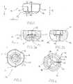
- FIG. 1shows a side view of an inventive fixing device 10.
- the fixing device 10has a base body 11.
- the main body 11is a receptacle of a support structure, for example in the receptacle 63 in an implant plate 61, for example according to FIG. 6 used.
- the main bodyhas a clamping region 13. In the clamping region 13 of the main body 11 by contact with the inner wall 65 of the receptacle 63 (s. FIG. 6 ) compressible.
- the main body 11also has slots 15 which extend in the axial direction A. Because of the slots 15, the base body 11 can be compressed in the radial direction r (ie in a plane perpendicular to the axial direction A).
- the main body 11has an outer contour 14.
- the outer contour 14is formed at least in a region 18 in the axial direction A rounded. Due to the rounded outer contour 18, the base body or the fixing device can be inserted in a plurality of different angular positions in a receptacle
- the main body 11is also provided with a bore 12 (s. FIGS. 2a and 2b ) Mistake.
- the bore 12serves to receive an elongated element. By compression in the radial direction r, the diameter D of the bore 12 can be reduced. As a result, an elongate element inserted into the bore 12, such as typically a wire, is clamped. To increase the clamping effect
- the inner surface 17 of the bore 12may be provided with a surface structuring.
- FIG. 2bshows a section through the base body 11 in a plane along the slot 15. Like FIG. 2b shows, the slot 15 extends from one edge of the main body 11 to the bore 12th
- the outer contour of the base body 10is provided in a plane perpendicular to the axial direction A with three clamping surfaces 16.
- the clamping surfaces 16widen radially as viewed against the circumferential direction U. If the base body 11 in a correspondingly shaped opening with radial projections 64 (s. FIG. 6 ) is used and rotated in the circumferential direction U, the clamping surfaces 16 engage with the projections 64. This results in a compression in the radial direction.
- FIG. 4shows in bottom view, the three, each 120 ° offset from each other, in FIG. 4 exactly radially extending slots 15.
- the slots 15extend approximately over two-thirds of the height of the base body 11.
- the slots curved or tangentialit is also conceivable to form the slots curved or tangential.
- the inventive fixing deviceis formed in medical applications of a biocompatible material.
- a biocompatible materialTypically, titanium can be used.
- Others, such as Stainless or bioresorbable materialsare also conceivable.
- alloys having a shape memory propertyfor example NiTiNol or generally superelastic materials and, for example, also plastic.
- the dimension of the fixing device according to the inventiondepends on the respective field of application.
- fixation deviceswith a diameter of approximately 2 to 7 mm, bores with a diameter of approximately 0.75 to 1.4 mm and fixation devices with a total height of approximately 1 to 5 mm are conceivable.
- the slotsmay typically have a slot width of 0.2 to 0.3 mm and extend over a height of 0.3 to 1.5 mm.
- endoscopeswith diameters of 10-50 mm and bores with diameters of 5-40 mm are known.
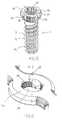
- FIG. 5shows a three-dimensional view of a trained as a screw 1 fixing device.
- a screw shank 2which is provided with a screw thread 3.
- the screwis according to WO 04/086990 educated.
- the screw shaft 2 with the thread 3may have advantageous properties. But it is also conceivable to omit the screw shaft or form as a pin without screw thread.
- FIG. 6shows an example of a receptacle 63 for the fixing device 10.
- the receptacle 63has an inner wall 65.
- the Inner wall 65is provided with radially inwardly extending projections 64.
- the receptacle 63is shown as part of an implant plate 61.
- the recordingis according to WO 04/086990 educated.
- corresponding openingscan be provided in any support structures in which elongated elements are to be used by means of the fixing device.
- plate 61 with the opening 63otherwise corresponds to the identical in WO 04/086990 shown plate.
- the inner wall 65is partially formed in the axial direction A spherical, spiral, parabolic, elliptical or hyperbolic, so that the fixing device with its rounded outer contour 18 multidirectionally inserted into the opening 63 and can be clamped by rotating in the direction U in the opening 63.
- FIG 7aschematically shows an embodiment of a non-inventive fixing device.
- the fixing device according to Figure 7ais designed as a screw 1 '.
- the screw 1'In the area of the screw head 10 ', the screw 1' has a base body 11 '.
- the main body 11 'is provided with a in the axial direction of the screw 1' extending slot 15 '. Through the slot 15 ', a clamping region 13' is formed.
- the main body 11 'is formed similar to that in FIGS. 1 to 4 shown basic body.
- FIG. 7bshows a further alternative embodiment.
- An implant plate 41is used internally as a fixator for a radius head K.
- wires 40 introduced into the bones Kare fastened in openings 43 on the plate 41 by means of the fixing devices 10 described above.
- the fixing devices 10allow axial fixation of the wires 40.
- the wirescan be inserted at different angles relative to the surface of the plate and positioned in their angular position by blocking.
- FIG. 7bis an inner contour for receiving a tool, typically shown a screwdriver. With this tool, the fixing device 10 can be subjected to a torque, rotated and thereby jammed.
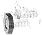
- FIG. 8shows a further possible application of a fixing device according to the invention.
- Two implant plates 61, 62are positioned on two sides of a bone K.
- Two wires 60are inserted through the bone and guided through corresponding holes 63 in the implant plates 61, 62.
- the wires 60are fixed in the holes 63 angularly stable. Due to the above-described free positioning can be choose the direction of the wires 60 freely.
- the two implants 61, 62are connected to one another along the wires 60 in the region of the openings 63 and thereby stabilized. In this way, a force can be applied even if the bone material is not present in sufficient quantity or quality to accommodate a conventional bone screw.
- FIG. 8shows Osteosyntheseset from the plates 61, 62, the wires 60 and the fixing devices 10 allows the use of such implants, for example, in osteoporotic bone.
- FIGS. 9a and 9balternative embodiments of such osteosynthesis sets are shown.
- FIG. 9ashows an alternative embodiment of a Osteosynthesesets.
- two implant plates 71, 72are connected to wires 100.
- Each wire 100is similar to the one in FIG. 8 shown fixed by means of a clamping device 10 in a receptacle of an implant plate 71.
- the fixationis essentially as related to FIG. 8 explained.
- the wire 100has a thread.
- a nut 73for example made of PEEK, is screwed onto the thread and thus fixes the wire 100 in the region of the second implant plate 72.
- the stabilizationcan be generated in the direction R, where R does not have to be aligned perpendicular to the plane of the plate.
- FIG. 9bare two implant plates 71, 72 connected by screws 70 together.
- a nut 73 or a plate with an openingis in the region of a plate 72 with the end of the Screw 70 connected.
- the screws 70supported with their screw heads 74 on the other plate 71 from. Even with this stabilization, a connection of the implant plates 71, 72 in the direction R can be achieved, wherein R does not have to be aligned perpendicular to the plane of the plate.
- a motheris understood here in particular any type of abutment for the wire.
- the nutdoes not necessarily have to be arranged parallel to the plate plane.
- the mothercan also have a certain swing range. Even the mother can be blocked.
- the motherdoes not necessarily have an opening.
- a self-drilling wire tipcan also drill a hole.
- the mothercan also be pre-assembled in the plate.
- a wiremust be set.
- a target deviceis used to thread the wire into the start and target hole.
- the connecting line of these two pointscorresponds to the introduction of the wire of the wire axis.
- the clamping elementsare then threaded and blocked by rotation in the circumferential direction U in the opening.
- a pivoting of the fixing device 10is possible due to the rounded outer contour seen in the axial direction, but limited by the geometry of the implant plates 61, 62 to a certain angular range, typically a maximum of +/- 15 ° .
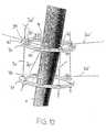
- FIG. 10shows schematically the application of inventive fixing devices in a fixator externally.
- the external fixatortypically for a humerus, has two rings 31.
- the rings 31are to be stabilized together by wires 30.
- fixing devices 10are mounted in openings 33 of the rings or in openings 33 of additional elements applied to the rings.
- the fixing devices 10 and the openings 33are formed as described above.
- the fixing devices 10may be provided with an extension 4, which serves for receiving a tool or for (manual) manipulation.
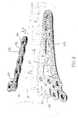
- FIG. 11schematically shows an application of the inventive fixing device 10 for temporary, intraoperative fixation of the metacarpal bone.
- a fixing ring 21is on the hand or hovers over it and is attached to the operating table, for example with a fixing device as described above.
- Fixing wires 20are used for temporary fixation.
- the wires 20are passed through the bore 12 (see eg Fig. 2a and 2b ) of the fixing device 10.
- the fixing devices 10are screwed into corresponding openings 23 on the fixing ring 21.
- the fixing devices 10can be fixed in the openings 23 and radially compress.
- the wire 20is fixed in the axial direction in the fixing device 10, the fixing ring is also fixed against tilting.
- the openings 23are formed similar to those in connection with the implant plate in FIG. 6 illustrated opening. Depending on the application can be different Sizes of fixing devices 10 are used.
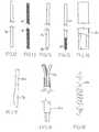
- FIGS. 12 to 19show various embodiments of elongated elements which can be used in the inventive fixing device 10.
- FIG. 12schematically shows a simple wire 20 without specific contouring of the surface.
- FIG. 13shows a wire 80, which is provided over its entire length with a thread 81.
- Typical applicationsare, for example, K wires with short (about 20 mm) thread or with a thread on the entire length.
- the thread on the tipmay serve to secure a bone fragment against axial displacement on the K-wire.
- the thread on the entire shaftalso provides a cost-effective structuring transverse to the longitudinal axis, which can also serve to reinforce the holding force.
- knurlsextending in the longitudinal direction or in the transverse direction are also conceivable.
- FIG. 14shows a wire-like element 90, which is provided at its end with a trocar-cut 91.
- FIG. 15shows a wire-like element 100, which is provided only at its tip with a thread 101.
- FIG. 16shows an endoscope tube 50.
- a tubular shaped elongated element as in FIG. 16can also be used in conjunction with a lancet cut.
- FIG. 17shows a scalpel 120, which can be fastened with its shaft 121 in a fixing device according to the invention.
- FIG. 18shows a tubular member 131 which serves to receive a wire bundle 132.
- the element 131In the osteoporotic bone of the upper arm there is a risk that the articular surface collapses.
- the ends of the wire bundlecan support the osteoporotic bone in the region of the articular surface from the inside.
- the tubular elementthen assumes the function of an elongate element, which in a fixing device 10 as described above (see, eg Fig. 1 and 2 ) is fixed. It is also conceivable to provide the tube with a suitable outer contour (not shown), so that the tube fulfills the object of a fixing device according to the invention for holding the wire bundle.
- FIG. 19shows a spring-like element 141.
- the spring-like element 141consists of two nested coil springs. As a spring element and leaf springs, coil springs are conceivable, but also a spring of two telescoped coil springs.
- the elongated elementsconsist of suitable materials.
- titaniumcan be used with implantable elements.
Landscapes
- Health & Medical Sciences (AREA)
- Orthopedic Medicine & Surgery (AREA)
- Surgery (AREA)
- Life Sciences & Earth Sciences (AREA)
- Heart & Thoracic Surgery (AREA)
- Nuclear Medicine, Radiotherapy & Molecular Imaging (AREA)
- Engineering & Computer Science (AREA)
- Biomedical Technology (AREA)
- Neurology (AREA)
- Medical Informatics (AREA)
- Molecular Biology (AREA)
- Animal Behavior & Ethology (AREA)
- General Health & Medical Sciences (AREA)
- Public Health (AREA)
- Veterinary Medicine (AREA)
- Surgical Instruments (AREA)
Abstract
Description
Translated fromGermanDie Erfindung betrifft eine Fixiervorrichtung, eine Kombination einer solchen Fixiervorrichtung mit einem länglichen Element und eine entsprechende Anordnung mit einer Haltestruktur sowie ein Osteosyntheseset.The invention relates to a fixing device, a combination of such a fixing device with an elongated element and a corresponding arrangement with a holding structure and an osteosynthesis set.
In der Knochenchirurgie werden verschiedene Arten von Fixiervorrichtungen verwendet. Bei verschiedenen Indikationen muss dabei ein längliches Element wie beispielsweise ein Kirschnerdraht an einer Haltestruktur wie beispielsweise einem internen oder externen Fixateur befestigt werden. Zur Befestigung der Drähte in der Haltestruktur sind verschiedene Anordnungen bekannt.In bone surgery, various types of fixators are used. In various indications, an elongated element such as a Kirschner wire must be attached to a support structure such as an internal or external fixator. For attachment of the wires in the support structure, various arrangements are known.
Aus
Aus
Weitere Fixiervorrichtungen für längliche Elemente sind aus
Alle diese bekannten Lösungen sind aber mit verschiedenen Nachteilen behaftet. Insbesondere bestehen viele der bekannten Lösungen aus einer Mehrzahl von einzelnen Elementen. Die Herstellung und Anwendung ist daher aufwändig und auch teuer. Ein weiterer Nachteil von bekannten Lösungen besteht darin, dass oft die zu fixierenden länglichen Elemente nur in eine Richtung oder nur mittels komplexen konstruktiven Lösungen multidirektional in verschiedene Richtungen befestigt werden können.However, all these known solutions are subject to various disadvantages. In particular, many of the known solutions consist of a plurality of individual elements. The production and application is therefore complicated and expensive. A further disadvantage of known solutions is that often the elongated elements to be fixed can be fastened in different directions only in one direction or only by means of complex constructive solutions in a multidirectional manner.
Die Veränderung der Winkellage einer solchen Klemmvorrichtung ist nicht oder nur dank zusätzlichen Bauteilen möglich.The change in the angular position of such a clamping device is not possible or only thanks to additional components.
Es ist daher eine Aufgabe der vorliegenden Erfindung, die Nachteile des Bekannten zu vermeiden, insbesondere also eine Fixiervorrichtung zum Fixieren von länglichen Elementen zu schaffen, welche einfach und kostengünstig herstellbar und auf eine einfache Art und Weise handhabbar ist. Trotzdem soll es die Fixiervorrichtung ermöglichen, die Richtung des zu fixierenden länglichen Elementes möglichst frei zu wählen und gegebenenfalls zu korrigieren. Eine weitere Aufgabe der vorliegenden Erfindung besteht darin, eine entsprechende Fixiervorrichtung zu schaffen, welche sich auf einfache Art und Weise re-positionieren lässt, beispielsweise zum Fixieren eines länglichen Elements unter einem anderen Winkel als ursprünglich vorgesehen.It is therefore an object of the present invention to avoid the disadvantages of the known, so in particular to provide a fixing device for fixing elongated elements, which can be easily and inexpensively manufactured and a simple Way is manageable. Nevertheless, it should allow the fixing device to choose the direction of the elongated element to be fixed as free as possible and correct if necessary. A further object of the present invention is to provide a corresponding fixing device which can be repositioned in a simple manner, for example for fixing an elongate element at an angle other than originally provided.
Eine weitere Aufgabe der vorliegenden Erfindung besteht darin, eine solche Fixiervorrichtung in Kombination mit einem länglichen Element sowie eine Anordnung mit einer solchen Kombination und mit einer zusätzlichen Haltestruktur zu schaffen, welche die oben genannten Aufgaben ebenfalls lösen.A further object of the present invention is to provide such a fixing device in combination with an elongated element and an arrangement with such a combination and with an additional support structure, which also solve the above-mentioned objects.
Ein weiterer Aspekt der Erfindung betrifft ausserdem ein Osteosyntheseset aus wenigstens zwei Implantatplatten und einer solchen Fixiervorrichtung. Vor allem bei der Versorgung von osteoporotischen Knochen besteht häufig das Problem, dass sich Implantatplatten mit Gewindeschrauben nicht ausreichend fest im Knochenmaterial verankern lassen. Es ist eine Aufgabe gemäss diesem Aspekt der Erfindung, ein Osteosyntheseset zu schaffen, welches sich zur Lösung der bekannten Probleme eignet, welches also insbesondere eine feste Fixierung der Implantatplatten auch ermöglicht, wenn auf Grund von nicht ausreichendem oder ungeeignetem Knochenmaterial eine herkömmliche Fixierung mit einer Schraube nicht möglich ist oder die Haltung der Schraube nicht genügend Stabilität bietet.Another aspect of the invention also relates to an osteosynthesis set of at least two implant plates and such a fixing device. Especially in the care of osteoporotic bones, there is often the problem that implant plates with threaded screws can not be sufficiently firmly anchored in the bone material. It is an object according to this aspect of the invention to provide an osteosynthesis set which is suitable for solving the known problems, which therefore also enables a firm fixation of the implant plates, if a conventional fixation with a screw due to inadequate or unsuitable bone material is not possible or the attitude of the screw does not provide sufficient stability.
Erfindungsgemäss werden diese Aufgaben mit einer Fixiervorrichtung, einer Kombination einer solchen Fixiervorrichtung mit einem länglichen Element, einer Anordnung mit einer solchen Kombination sowie mit einem Osteosyntheseset mit den Merkmalen der unabhängigen Patentansprüche gelöst.According to the invention, these objects are achieved with a fixing device, a combination of such a fixing device with an elongate element, an arrangement with such a combination and with an osteosynthesis set having the features of the independent patent claims.
Die erfindungsgemässe Fixiervorrichtung dient zum Fixieren eines länglichen Elementes, insbesondere eines Drahtes, Stiftes, Rohrs oder eines Fadens, in einer Aufnahme einer Haltestruktur. Die Haltestruktur ist typischerweise eine Platte. Der Begriff Haltestruktur ist aber breit zu verstehen. Denkbar sind auch Anwendungen, bei denen die Haltestruktur in erster Linie die nachstehend beschriebenen Klemmkräfte aufbringt und nicht zum Halten der Fixiervorrichtung an sich. Die Fixiervorrichtung weist einen Grundkörper auf. Der Grundkörper ist mit einer Öffnung, insbesondere einer durchgehenden Bohrung zur Aufnahme des länglichen Elementes versehen. Die Öffnung kann sich in Längsrichtung erstrecken. Es ist aber auch denkbar, Öffnungen in Querrichtung (d.h. unter einem Winkel von mehr als 0° zur Längsachse) des Grundkörpers vorzusehen, beispielsweise für die Distraktion. Während die Öffnung zur Aufnahme des länglichen Elements typischerweise rund ausgebildet ist (v.a. wenn sie zur Aufnahme zylindrischen Gegenständen wie Drähten dient), sind auch andere Formen der Öffnung denkbar. Beispielsweise ist auch eine schlitzförmige Öffnung zur Aufnahme von flächigen länglichen Elementen denkbar. Anders gestaltete Öffnungen zur Aufnahme von profilierten länglichen Elementen sind ebenfalls denkbar.The fixing device according to the invention serves to fix an elongate element, in particular a wire, pin, tube or a thread, in a receptacle of a holding structure. The support structure is typically a plate. However, the term holding structure is to be understood broadly. Also conceivable are applications in which the holding structure primarily applies the clamping forces described below and not for holding the fixing device per se. The fixing device has a base body. The main body is provided with an opening, in particular a through hole for receiving the elongated element. The opening may extend in the longitudinal direction. However, it is also conceivable to provide openings in the transverse direction (i.e., at an angle of more than 0 ° to the longitudinal axis) of the main body, for example for distraction. While the opening for receiving the elongate member is typically round (preferably when used to receive cylindrical objects such as wires), other shapes of the opening are also conceivable. For example, a slot-shaped opening for receiving flat elongated elements is conceivable. Differently designed openings for receiving profiled elongate elements are also conceivable.
Erfindungsgemäss ist der Grundkörper zumindest in einem äusseren Klemmbereich radial derart verformbar ausgebildet, dass die Dimension der Öffnung, insbesondere der Durchmesser der Bohrung reduzierbar ist. Unter äusserem Klemmbereich wird im Rahmen dieser Anmeldung derjenige Bereich verstanden, in welchem der Grundkörper durch Kontakt mit der Aufnahme in der Haltestruktur komprimiert ist. Der Grundkörper weist ausserdem eine Aussenkontur auf, die derart ausgebildet ist, dass beim Einsetzen der Fixiervorrichtung in die Öffnung der Haltestruktur der Klemmbereich radial so verformbar ist, dass das längliche Element in der Öffnung festklemmbar ist. Die Festklemmung kann dabei gesehen in der Richtung des länglichen Elementes axial auf gleicher Höhe erfolgen, auf der der Klemmbereich angeordnet ist. Es ist aber auch denkbar, eine Klemmung des länglichen Elementes axial beabstandet zum äusseren Klemmbereich des Grundkörpers vorzusehen. Das längliche Element kann vor dem Einsetzen in die Haltestruktur einfach in die Öffnung des Grundkörpers eingesetzt werden. Beim Einsetzen des Grundkörpers in die Aufnahme der Haltestruktur wird der Grundkörper auf Grund der gezielten Ausbildung seiner Aussenkontur radial komprimiert. Dadurch wird das längliche Element in der Öffnung des Grundkörpers festgeklemmt, so dass es in axialer Richtung nicht mehr verschoben werden kann. Die erfindungsgemässe Lösung ist besonders einfach, da neben dem länglichen Element und der Haltestruktur nur ein zusätzliches Bauteil, (die Fixiervorrichtung), notwendig ist, um das längliche Element zu fixieren.According to the invention, the base body is radially deformable at least in an outer clamping region such that the dimension of the opening, in particular the diameter of the bore, can be reduced. For the purposes of this application, the term "outer clamping area" is understood to mean that area in which the basic body is compressed by contact with the receptacle in the holding structure. The base body also has an outer contour, which is formed such that upon insertion of the fixing device into the opening of the holding structure of the clamping region is radially deformable so that the elongated element in the opening can be clamped. The clamping can be seen axially in the direction of the elongated element take place at the same height on which the clamping area is arranged. However, it is also conceivable to provide a clamping of the elongate element axially spaced from the outer clamping region of the base body. The elongated element can be easily inserted into the opening of the body prior to insertion into the support structure. When inserting the main body in the recording of the support structure of the base body is radially compressed due to the targeted training of its outer contour. As a result, the elongated element is clamped in the opening of the base body, so that it can not be moved in the axial direction. The inventive solution is particularly simple, since in addition to the elongated member and the support structure only an additional component, (the fixing device) is necessary to fix the elongated member.
Erfindungsgemäss ist die Fixiervorrichtung zumindest im Klemmbereich auf ihrer Aussenkontur mit wenigstens einer Klemmfläche versehen. Die Klemmfläche erweitert sich in Umfangsrichtung gesehen wenigstens teilweise radial. Ein Grundkörper mit einer solchen Struktur, jedoch ohne längliche Öffnung und ohne Schlitze, ist zum Erzeugen einer Verblockung einer Knochenschraube in einer Implantatplatte aus
Die erfindungsgemässe Fixiereinrichtung weist ausserdem am Grundkörper auf dessen Aussenkontur in Längsrichtung gesehen im Bereich der Klemmfläche eine gerundete Aussenkontur, insbesondere eine wenigstens teilweise etwa sphärische, spiralförmige, parabolische, elliptische oder hyperbolische Kontur auf. Ganz allgemein ist eine Kontur bevorzugt, dank der sich die Richtung der Fixiervorrichtung in einer Aufnahme einer Haltestruktur in einen bestimmten Winkelbereich nahezu uneingeschränkt einstellen lässt. Dazu sind keine zusätzlichen Bauteile wie Kugelgelenke, Klemmbacken oder ähnliches notwendig. Die Aussenseite des Grundkörpers und/oder die Aufnahme der Haltestruktur kann ausserdem strukturiert werden, beispielsweise mit Rillen oder Rändeln versehen werden.In addition, the fixing device according to the invention has a rounded outer contour, in particular an at least partially approximately spherical, spiral, parabolic, elliptical or hyperbolic contour, on the outer body on its outer contour in the longitudinal direction. In general, a contour is preferred, thanks to which the direction of the fixing device in a receptacle of a holding structure can be adjusted almost unrestrictedly within a certain angular range. There are no additional components such as ball joints, jaws or the like necessary. The outside of the base body and / or the receptacle of the support structure can also be structured, for example provided with grooves or knurls.
Gemäss einer ersten bevorzugten Ausführungsform der Erfindung ist die Fixiervorrichtung in ihrem Klemmbereich mit mindestens einem Schlitz versehen. Der Schlitz verläuft wenigstens teilweise in Richtung der Öffnung und endet wenigstens teilweise in der Öffnung. Der Schlitz kann bis zur Aussenwand der Fixiervorrichtung reichen. Der Schlitz muss nicht zwingend in einer Ebene verlaufen, er kann auch einen oder mehrere Knicke oder Krümmungen aufweisen. Auf Grund dieses wenigstens einen Schlitzes lässt sich der Grundkörper besonders einfach radial komprimieren. Ein Schlitz kann bereits ausreichend sein. Es kann aber auch eine beliebige grössere Anzahl von Schlitzen vorgesehen sein. Der oder die Schlitze sind beispielsweise in radialer Richtung angeordnet. Es ist aber auch denkbar, Schwächungen im Grundkörper durch tangentiale oder kurvenförmige Schlitze anzuordnen. Typischerweise verläuft der Schlitz genau in Richtung der Öffnung zur Aufnahme des länglichen Gegenstandes. Es ist aber auch denkbar, den Schlitz unter Winkeln bezogen auf die Achse der Fixiervorrichtung vorzusehen. Alternativ ist es aber auch denkbar, den Grundkörper aus einem elastischen Material auszubilden. In diesem Fall kann eine radiale Kompression auch ohne Schlitz erzielt werden. Ausserdem kann der Grundkörper zur Vereinfachung des Einsetzens des länglichen Elements auch aus mehreren, zueinander beweglichen Teilen ausgebildet sein. Denkbar sind zwei, mit einem Scharnier verbundene Teile. Diese Teile lassen sich zum Einsetzen des Elements aufklappen und wieder schliessen und dann miteinander verbinden. Die axiale Fixierung des länglichen Elementes erfolgt anschliessend wiederum in der vorstehend beschriebenen Art und Weise.According to a first preferred embodiment of the invention, the fixing device is provided in its clamping region with at least one slot. The slot extends at least partially in the direction of the opening and terminates at least partially in the opening. The slot may extend to the outer wall of the fixing device. The slot does not necessarily have to run in one plane, it may also have one or more kinks or bends. Due to this at least one slot, the base body can be particularly easily compressed radially. A slot may already be sufficient. But it can also be provided any larger number of slots. The slot or slots are arranged, for example, in the radial direction. But it is also conceivable to arrange weakenings in the body by tangential or curved slots. Typically, the slot is exactly in the direction of the opening for receiving the elongated object. But it is also conceivable to provide the slot at angles relative to the axis of the fixing device. Alternatively, it is also conceivable to form the base body of an elastic material. In this case, a radial compression can be achieved without a slot. In addition, the base body may be formed to simplify the insertion of the elongated member also from a plurality of mutually movable parts. Conceivable are two parts connected by a hinge. These parts can be opened to insert the element and close again and then connect with each other. The axial fixation of the elongated element is then again in the manner described above.
Es ist ausserdem auch denkbar, den Grundkörper aus mehreren Materialien und mit mehreren Komponenten auszubilden. Beispielsweise könnte elastisches Material für die Klemm-Zone und zähes Material für die Verblockungs- und Schraubendreher-Zone verwendet werden. Eine solche Fixiervorrichtung ist z.B. mit Mehrkomponenten-Spritzguss realisierbar.It is also conceivable to form the base body of several materials and with several components. For example, elastic material could be used for the clamp zone and tough material for the lock and screwdriver zone. Such a fixing device can be realized, for example, with multi-component injection molding.
Gemäss einer weiteren bevorzugten Ausführungsform der Erfindung ist die Fixiervorrichtung zumindest in ihrem Klemmbereich entsprechend als Schraubenkopf ausgebildet. Die Ausbildung als Schraubenkopf ermöglicht insbesondere ein einfaches Drehen der Fixiervorrichtung in Umfangsrichtung. Bei der vorstehend beschriebenen Ausbildung mit sich in Umfangsrichtung radial erweiternden Klemmflächen lässt sich die radiale Kompression auf besonders einfache Art und Weise durch Drehen mittels eines Schraubendrehers erzeugen, z.B. mit einem Kreuz-Schlitz, Torx, Innensechskant oder Variationen davon, wie beispielsweise der "HexaDrive" der Anmelderin.According to a further preferred embodiment of the invention, the fixing device is designed at least in its clamping region correspondingly as a screw head. The training as a screw head allows in particular a simple rotation of the fixing device in the circumferential direction. In the embodiment described above with radially widening clamping surfaces in the circumferential direction, the radial compression can be produced in a particularly simple manner by turning by means of a screwdriver, for example with a cross-slot, Torx, Allen or variations thereof, such as the applicant's "HexaDrive".
Die Fixiervorrichtung kann an ihrem Grundkörper zusätzlich mit einem Schraubenschaft mit einem Schraubengewinde versehen sein. Es ist aber auch denkbar, die Fixiervorrichtung zusätzlich mit einem Schaft eines Pins zu versehen. Je nach Anwendung kann also eine Fixiervorrichtung, die ausschliesslich aus dem Grundkörper besteht oder eine Fixiervorrichtung, bei welcher der Grundkörper zusätzlich mit dem Schaft eines Pins oder einer Schraube versehen ist, vorteilhaft sein.The fixing device may be additionally provided on its main body with a screw shank with a screw thread. However, it is also conceivable to additionally provide the fixing device with a shaft of a pin. Depending on the application, therefore, a fixing device, which consists exclusively of the main body or a fixing device, in which the main body is additionally provided with the shaft of a pin or a screw, be advantageous.
Gemäss einer weiter bevorzugten Ausführungsform der Erfindung kann die Fixiervorrichtung, wenn sie in ihrem Klemmbereich als Schraubenkopf ausgebildet ist, ausserdem oberhalb des Klemmbereichs mit einem Fortsatz versehen sein. Der Fortsatz ist als Aufnahme für einen Schraubendreher ausgebildet. Damit kann besonders einfach ein Drehmoment auf die Fixiervorrichtung aufgebracht werden.According to a further preferred embodiment of the invention, the fixing device, if it is formed in its clamping region as a screw head, also be provided above the clamping region with an extension. The extension is designed as a receptacle for a screwdriver. This can be applied to the fixing device is particularly easy torque.
Gemäss einem weiteren bevorzugten Ausführungsbeispiel der Erfindung erstreckt sich der wenigstens eine Schlitz in Längsrichtung der Fixiervorrichtung gesehen wenigstens über den Klemmbereich. Es ist aber auch denkbar, den Schlitz oder die Schlitze über einen längeren, axialen Bereich zu erstrecken, um die Verformbarkeit bzw. die Flexibilität des Grundkörpers weiter zu erhöhen. Maximal erstrecken sich die Schlitze über die ganze Länge der Fixiervorrichtung. Durch gezielte Wahl der Länge der Schlitze lässt sich die auf das längliche Element erzielbare Klemmwirkung einstellen.According to a further preferred embodiment of the invention, the at least one slot extends in the longitudinal direction of the fixing device at least over the clamping area. However, it is also conceivable to extend the slot or the slots over a longer, axial area in order to further increase the deformability or the flexibility of the basic body. At most, the slots extend over the entire length of the fixing device. By selective choice of the length of the slots, the achievable on the elongated element clamping action can be adjusted.
Gemäss einer weiteren bevorzugten Ausführungsform der Erfindung kann die Innenfläche der Öffnung strukturiert sein. Auf diese Weise lässt sich durch zusätzlichen Formschluss eine auf Grund der radialen Kompression vergrösserte Rückhaltewirkung in axialer Richtung erzielen. Mit anderen Worten heisst dies, dass bei einer bestehenden Klemmkraft eine grössere Kraft auf dem länglichen Element in Achsrichtung notwendig wäre, um dies aus der Fixiervorrichtung auszureissen.According to a further preferred embodiment of the invention, the inner surface of the opening may be structured. To this Way can be achieved by additional positive fit increased due to the radial compression retention effect in the axial direction. In other words, this means that in the case of an existing clamping force, a greater force would be necessary on the elongate element in the axial direction in order to pull it out of the fixing device.
Entsprechend den vorstehenden Ausführungen besteht ein Aspekt der Erfindung auch darin, dass eine an sich bekannte Verblockungsschraube zusätzlich mit einer Längsbohrung versehen und im Bereich des Schraubenkopfes mit wenigstens einem Schlitz versehen wird. Besonders bevorzugt wird dabei eine Verblockungsschraube verwendet, wie sie in
Ein weiterer Aspekt der Erfindung besteht daher in der Verwendung einer solchen Verblockungsschraube zum Fixieren eines länglichen Elementes in einer Haltestruktur. Durch die Verwendung einer multidirektionalen Verblockungsschraube lässt sich das längliche Element in Achsrichtung aber auch in einer bestimmten, in einem Winkelbereich frei wählbaren Winkellage fixieren.A further aspect of the invention is therefore the use of such a locking screw for fixing an elongated element in a support structure. By using a multidirectional locking screw, the elongate element can be fixed in the axial direction but also in a specific angular position that can be freely selected in an angular range.
Noch ein weiterer Aspekt der Erfindung betrifft die Kombination einer wie vorstehend beschriebenen Fixiervorrichtung mit einem länglichen Element. Dabei ist das längliche Element ausgewählt aus der Gruppe bestehend aus Drähten, Stäben, Stiften, Profilen, Federn, Hohlrohren oder einem Instrument zur Manipulation wie z.B. einem Skalpell oder Spatel (z.B. für Manipulationen am Gehirn). Wenn das längliche Element aus Draht, Stab oder Stift ausgebildet ist, sind beispielsweise Anwendungen zusammen mit einem Fixateur intern oder einem Fixateur extern möglich. Wenn das längliche Element als Profil oder Hohlrohr ausgebildet ist, sind beispielsweise auch Anwendungen als Endoskopierohr oder zur Fixierung einer Bohrerführung denkbar. Wenn das längliche Element als Halterung eines Skalpells ausgebildet ist, lässt sich ausserdem die erfindungsgemässe Fixiervorrichtung als Skalpellhalter zum Halten eines Skalpells einsetzen. Dabei kann der Schaft des Skalpells in die längliche Bohrung eingesetzt werden. Bei einer solchen Anwendung ist es aber auch denkbar, keine längliche Bohrung im Fixierelement vorzusehen, sondern direkt einen Teil der Klinge des Skalpells in am Fixierelement vorhandene Schlitze einzufügen.
Zum Erhöhen der axialen Klemmwirkung kann ausserdem auch das längliche Element eine strukturierte Oberfläche aufweisen.Yet another aspect of the invention relates to the combination of a fixing device with an elongate element as described above. The elongated element is selected from the group consisting of wires, rods, pins, profiles, springs, hollow tubes or an instrument for manipulation such as a scalpel or spatula (eg for manipulation of the brain). When the elongated member is formed of wire, rod or pin, for example, applications are possible together with a fixator internally or a fixator externally. If the elongated element is designed as a profile or hollow tube, for example, applications as Endoskopierohr or for fixing a drill guide are conceivable. If the elongated element is designed as a holder for a scalpel, the fixing device according to the invention can also be used as a scalpel holder for holding a scalpel. The shaft of the scalpel can be inserted into the elongated bore. In such an application, however, it is also conceivable to provide no elongated bore in the fixing element, but to insert directly a part of the blade of the scalpel in existing on the fixing slots.
In addition, to increase the axial clamping effect, the elongate element may also have a structured surface.
Es ist ausserdem denkbar, je nach Anwendung das längliche Element mit einem Gewinde oder mit einem Rändel in Längs- oder Querrichtung oder auch mit einer Bohrerwendel zu versehen. Gemäss einer weiteren bevorzugten Ausführungsform kann das längliche Element mit einer Spitze versehen sein, die als Trokar oder Lanzette ausgebildet ist oder die mit einem selbstschneidenden oder selbstbohrenden Gewinde versehen ist.It is also conceivable, depending on the application, to provide the elongate element with a thread or with a knurl in the longitudinal or transverse direction or else with a drill helix. According to a further preferred embodiment, the elongated element may be provided with a tip which is formed as a trocar or lancet or which is provided with a self-tapping or self-drilling thread.
Denkbar ist weiter ein Kabel/eine Schnur als längliches Element zur Übertragung von Zugkräften oder zur Verbindung von gerissenen Weichteilen wie Sehnen oder Bändern oder zur Fixierung von Knochenfragmenten.Also conceivable is a cable / cord as an elongated element for transmitting tensile forces or for connecting torn soft tissues such as tendons or ligaments or for fixing bone fragments.
Ein weiterer Aspekt der Erfindung betrifft eine Anordnung aus einer wie obenstehend beschriebener Kombination einer Fixiervorrichtung und eines länglichen Elementes zusammen mit einer Haltestruktur. Die Haltestruktur weist wenigstens eine Aufnahme für eine Fixiervorrichtung auf.Another aspect of the invention relates to an assembly of a combination of a fixing device and an elongated member as described above together with a support structure. The holding structure has at least one receptacle for a fixing device.
Die Aufnahme für die Fixiervorrichtung ist dabei besonders bevorzugt mit radial nach innen gerichteten Vorsprüngen oder Verjüngungen versehen. Diese Verjüngungen führen im Zusammenwirken mit den Klemmflächen an der Fixiervorrichtung zu einer radialen Kompression des Grundkörpers. Um auf möglichst einfache Weise ein multidirektionales Positionieren der Fixiervorrichtung und damit auch des darin gehaltenen länglichen Elementes zu ermöglichen, ist die Öffnung ausserdem bevorzugt mit einer Innenwand versehen, die in Längsrichtung wenigstens teilweise etwa sphärisch, spiralförmig, parabolisch, elliptisch oder hypobolisch ausgebildet ist. Insbesondere ist die Öffnung wie gemäss Offenbarung und Ansprüchen in
Die Haltestruktur kann beispielsweise eine Haltestruktur zur Aufnahme eines Endoskopierohrs sein, welches mit der Fixiervorrichtung in der Haltestruktur gehalten wird. Dabei ist das längliche Element als Endoskopierohr ausgebildet.The holding structure can be, for example, a holding structure for receiving an endoscopy tube, which is held in the holding structure by the fixing device. In this case, the elongated element is designed as Endoskopierohr.
Die Haltestruktur kann auch als temporäres, intraoperatives Stützelement ausgebildet sein, beispielsweise als Fixierring für ein Arthrodeseset.The holding structure can also be designed as a temporary, intraoperative support element, for example as a fixation ring for an arthrodesis set.
Typische temporäre intraoperative Anwendungen sind Anwendungen, bei denen bestimmte Knochen zeitlich befristet fixiert werden sollen. Vor dem Ende des chirurgischen Eingriffs wird die entsprechende Stützstruktur entfernt. Indikationen sind beispielsweise Arthrodese oder Teilarthrodese des Handgelenks, die Neurochirurgie, Osteotomien, Korrekturen oder Frakturversorgungen sowie minimal-invasive Eingriffe, wie beispielsweise Transbuccal-Eingriffe oder Wirbelsäulenchirurgie. Als Fixateur extern wird eine Anwendung verstanden, bei der die stabilisierenden oder fixierenden Strukturen postoperativ ausserhalb des Körpers zur Stilllegung von Knochenbewegungen und damit zur Heilung von Frakturen verwendet werden. Es ist aber auch denkbar, gewisse Freiheitsgrade von Strukturen (z.B zwei durch ein Gelenk verbundene Knochen) zu fixieren und andere Freiheitsgrade der gleichen Struktur wiederum gezielt in ihrer Beweglichkeit zu belassen (dynamischer Fixateur Externe). Dies dient einer frühen postoperativen physiotherapeutischen Beübung zur Verhinderung von Verklebungen von Weichteilen und Versteifungen der betroffenen Gelenke. Typischerweise können dies Osteotomien, Korrekturen oder Frakturversorgungen sein. Denkbar ist ebenfalls die Anwendung bei einem Ringfixateur, wobei die Fixierung mehrerer Ringe untereinander ebenfalls über die erfindungsgemässe Fixiervorrichtung erfolgen kann. Denkbar ist überdies der Einsatz beispielsweise bei Oberarmfrakturen, wobei mit einem Gewindedraht die Gelenk-Kugel gefasst wird und über eine Mutter, die sich am Schraubenkopf abstützt die Position sehr fein eingestellt werden kann (pull-push-Instrument).Typical temporary intraoperative applications are applications in which certain bones are to be fixed for a fixed period of time. Before the end of the surgical procedure, the corresponding support structure is removed. Indications include, for example, arthrodesis or partial arthrodesis of the wrist, neurosurgery, osteotomies, corrections or fracture restorations as well as minimally invasive interventions, such as transbuccal interventions or spine surgery. External fixation is understood as an application in which the stabilizing or fixing structures are postoperatively removed outside the body to shut down bone movements and thus to heal Fractures are used. However, it is also conceivable to fix certain degrees of freedom of structures (eg two bones connected by a joint) and in turn to selectively leave other degrees of freedom of the same structure in their mobility (dynamic fixator external). This serves for early postoperative physiotherapeutic exercise to prevent the adhesion of soft tissues and stiffening of the affected joints. Typically, these may be osteotomies, corrections or fracture restorations. Also conceivable is the application in a ring fixator, wherein the fixing of several rings can also be done with each other via the fixing device according to the invention. It is also conceivable use, for example, in humeral fractures, with a threaded wire, the joint ball is taken and a mother who is supported on the screw head, the position can be very finely adjusted (pull-push instrument).
Die Haltestruktur kann ausserdem auch durch einen Operationsrahmen gebildet sein, der mit der Fixieranordnung an einem OP-Tisch befestigbar ist, beispielsweise in Anwendungen der Neurochirurgie zum Halten von Bohr- oder Führungshülsen oder von Spateln.The holding structure can also be formed by a surgical frame which can be fastened with the fixing arrangement on an operating table, for example in applications of neurosurgery for holding drill or guide sleeves or spatulas.
Bei der Anwendung als Fixateur intern verbleibt die Anordnung als Implantat zur Stilllegung von Knochenbewegungen und zur Heilung von Frakturen dauerhaft im Körper. Typische Anwendungen können Arthrodese oder Teilarthrodese, die Wirbelversteifung, die gelenksnahe Versorgung von Röhrenknochen, die Epiphyse, alle Osteotomien, Korrekturen oder Frakturversorgungen, die Drahtosteosynthese, ausgehend von einer Platte mit mindestens einem Loch oder die skelettale Verankerung in der Kieferorthopädie sein. Denkbar ist auch ein Drahtfixateur oder Kabelfixateur zum Erzeugen von Zugkräften bei Weichteilen.When used internally as a fixator, the assembly remains permanently implanted in the body as an implant for stopping bone movement and healing fractures. Typical applications may include arthrodesis or partial arthrodesis, vertebral stiffening, joint-proximal provision of long bones, epiphysis, all osteotomies, corrections or fracture restorations, wire osteosynthesis from a plate with at least one hole, or skeletal anchorage in orthodontics. Also conceivable is a wire fixator or cable fixator for generating tensile forces in soft tissues.
Bei der Anwendung als Endoskop können durch die Bohrung in der Fixiervorrichtung Manipulationen im Körper (beispielsweise in der Neurochirurgie, in der Mund-, Kiefer-, oder Gesichtschirurgie, insbesondere transbuccal, oder bei der Chirurgie der Wirbelsäule oder des Beckens) vorgenommen werden.When used as an endoscope, manipulations in the body (for example in neurosurgery, in oral and maxillofacial surgery, in particular transbuccal surgery or in spine or pelvic surgery) can be performed through the hole in the fixation device.
In den drei letztgenannten Fällen ist das längliche Element typischerweise ein Draht bzw. ein Rohr/eine Hülse. Schliesslich kann die Haltestruktur auch als Halterung für ein Instrument wie ein Skalpell ausgebildet sein, wobei in diesem Fall das längliche Element der Klingenschaft des Skalpells oder ein Teil der Klinge ist.In the latter three cases, the elongate member is typically a wire or tube. Finally, the holding structure can also be designed as a holder for an instrument, such as a scalpel, in which case the elongated element of the blade shaft of the scalpel or a part of the blade.
Während vorliegend in erster Linie chirurgische Anwendungen beschrieben wurden, sind auch andere Anwendungen der erfindungsgemässen Fixiervorrichtung, der Kombination mit einem länglichen Element und der erfindungsgemässen Anordnung denkbar. Beispielsweise lassen sich solche Konstruktionen als Schnell-Spann-Systeme für K-Drähte/Bohrer bei Antriebs- oder Bohrmaschinen, als Spann-Mechanismus für Griffstücke z.B. in der Elektrochirurgie oder zur Knochen-Distraktion (z.B. von Gaumen, Alveolarkamm) einsetzen. Bei Anwendungen zur Distraktion kann das längliche Element z.B. zweiteilig ausgebildet sein, mit einem Teil mit einem Innen- und einem Teil mit einem Aussengewinde. Eine Fixiervorrichtung mit zwei quer angebohrten Grundkörpern dient zur Aufnahme je eines der Teile. Wenn die Grundkörper je in einem Knochenfragment verankert werden, lassen sich die Teile befestigen und zur Distraktion einsetzen.While primarily surgical applications have been described in the present case, other applications of the inventive fixing device, the combination with an elongate element and the inventive arrangement are conceivable. For example, such constructions can be used as quick-clamping systems for K-wires / drills in drive or boring machines, as gripping mechanism for handles e.g. in electrosurgery or bone distraction (e.g., palate, alveolar ridge). In distraction applications, the elongated element may be e.g. be formed in two parts, with a part with an inner and a part with an external thread. A fixing device with two transversely drilled bases serves to receive one of the parts. If the bodies are ever anchored in a bone fragment, the parts can be attached and used for distraction.
Denkbar sind aber auch weitere Anwendungen z.B. im Baubereich wie z.B. im Regalbau, im Gerüstbau, in der Dübeltechnik (evtl. mit axialer Kompression) oder zur Abstützung.Also conceivable, however, are other applications, for example in the construction sector, such as in racking, in scaffolding, in the dowel technique (possibly with axial compression) or for support.
Ein weiterer Aspekt der Erfindung betrifft ein Osteosyntheseset. Das Set besteht aus wenigstens zwei Implantatplatten beziehungsweise aus einer Implantatplatte mit wenigstens zwei Abschnitten. Die Implantatplatten bzw. die Abschnitte weisen jeweils wenigstens eine Aufnahme zur Aufnahme einer Verbindungsanordnung auf. Das Set weist ausserdem eine solche Verbindungsanordnung auf. Die Verbindungsanordnung ist in je eine Bohrung der Platten bzw. der Abschnitte einsetzbar. Dabei können die Implantatplatten mittels der Verbindungsanordnung der Implantatplatten miteinander verbunden und so stabilisiert werden. Die Platten werden daran gehindert, sich bezogen aufeinander entlang des länglichen Elements zu bewegen. Durch die feste Fixierung wird eine Verbindung einer oder mehrerer Platten untereinander erzeugt. An dieses Gerüst werden dann z.B. Fragmente reponiert und fixiert. Im Fall einer Platte mit zwei Abschnitten kann eine Verbindung von einem Abschnitt, z.B. einer Lasche einer Platte zu einem anderen Plattenabschnitt geschaffen werden. Dies kann z.B. sinnvoll sein, wenn die Verbindung zwischen den beiden Plattenabschnitten aus klinischen Gründen so ausgebildet sein muss, dass sie nur wenig oder keine Last übertragen kann oder sogar nach Herstellen der Verbindung aus klinischen Gründen entfernt wird.Another aspect of the invention relates to an osteosynthesis set. The set consists of at least two implant plates or an implant plate with at least two sections. The implant plates or the sections each have at least one receptacle for receiving a connection arrangement. The set also has such a connection arrangement. The connection arrangement can be used in each case a bore of the plates or the sections. In this case, the implant plates can be connected to one another by means of the connection arrangement of the implant plates and thus stabilized. The plates are prevented from moving relative to each other along the elongated element. Due to the fixed fixing a connection of one or more plates is generated with each other. To this framework are then e.g. Fragments reduced and fixed. In the case of a two-section disk, connection may be made from a section, e.g. a tab of a plate to another plate section are created. This can e.g. be useful if the connection between the two plate sections for clinical reasons, must be designed so that it can transmit little or no load or even removed after the connection for clinical reasons.
Dank der Verbindungsanordnung lassen sich zwei oder mehr solcher Implantatplatten an mehreren Seiten eines Knochens befestigen/verbinden, selbst wenn der Knochen auf Grund von Grösse oder Struktur (innerer Beschaffenheit) zur Aufnahme einer Knochenschraube zum Fixieren der Implantatplatten nicht geeignet ist.Thanks to the connection arrangement, two or more such implant plates can be attached / connected to multiple sides of a bone, even if the bone is not suitable for fixing a bone screw due to its size or structure (internal nature) for fixing the implant plates.
Denkbar ist es in diesem Zusammenhang auch, Implantatplatten mit laschenartigen, abgewinkelten Teilen zu versehen. Die Verbindungsanordnung kann dann in einer Aufnahme in dieser Lasche befestigt werden. Dies ist insbesondere vorteilhaft, wenn die vorstehend beschriebene Verbindung auf Grund der anatomischen Gegebenheiten mit flachen Platten nicht möglich ist, weil z.B. die Ebenen im Bereich der Aufnahme nicht in einem Winkel zueinander stehen, der kleiner ist als der Schwenkwinkel der Fixationselemente. Die abgewinkelten Teile bilden dann kleine Einheiten, die eine zur Verbindung brauchbare Position bieten.It is also conceivable in this context to provide implant plates with tab-like, angled parts. The connection assembly can then be mounted in a receptacle in this tab. This is particularly advantageous when the above described connection due to the anatomical conditions with flat plates is not possible because, for example, the planes in the region of the receptacle are not at an angle to each other, which is smaller than the pivot angle of the fixation elements. The angled parts then form small units which provide a position useful for connection.
Die Verbindungsanordnung weist eine Fixiervorrichtung in der eingangs beschriebenen Art und Weise auf. Damit lassen sich besonders einfach Spanndrähte in den Öffnungen der Implantatplatten befestigen. Für bestimmte Anwendungen wie beispielsweise craniomaxillofaciale Anwendungen ist es auch denkbar, den Winkel der Aufnahme bezogen auf die Platte schrägzustellen, also die Achse der Aufnahme nicht senkrecht zur Ebender Platte auszurichten. Damit kann eine Positionierung der Schrauben in einem weiteren Winkelbereichen erzielt werden, z.B. für eine um 30° schräg gestellte Aufnahme im Bereich von 15° (30°-15°) bis 45° (30°+15°). Insbesondere bei dünnen Platten kann in diesem Zusammenhang die Platte im Bereich der Aufnahme lokal verdickt werden. Damit wird Raum geschaffen zur schrägen Anordnung der Verblockungskontur in der Aufnahme.The connection arrangement has a fixing device in the manner described above. This makes it particularly easy to attach tension wires in the openings of the implant plates. For certain applications such as craniomaxillofaciale applications, it is also conceivable to tilt the angle of the recording with respect to the plate, so not align the axis of the recording perpendicular to the Ebender plate. Thus, positioning of the screws can be achieved in a wider range of angles, e.g. for a 30 ° inclined image in the range of 15 ° (30 ° -15 °) to 45 ° (30 ° + 15 °). In particular, with thin plates, the plate can be thickened locally in the field of recording in this context. This creates space for the oblique arrangement of the blocking contour in the receptacle.
Es ist aber auch denkbar, dass die Verbindungsanordnung ein längliches Element mit einem Gewinde an wenigstens einem Ende aufweist. Zusätzlich ist die Verbindungsanordnung in diesem Fall mit einem Verbindungselement wie z.B. einer Mutter versehen, in welche das Gewinde einschraubbar ist und mittels welcher das längliche Element in einer der Platten befestigbar ist.However, it is also conceivable that the connection arrangement has an elongate element with a thread on at least one end. In addition, the connection arrangement is provided in this case with a connecting element such as a nut, in which the thread can be screwed and by means of which the elongated element in one of the plates can be fastened.
Die Erfindung wird im Folgenden in Ausführungsbeispielen und an Hand der Zeichnungen näher erläutert. Es zeigen:
- Figur 1:
- Seitenansicht einer erfindungsgemässen Fixiervorrichtung;
- Figur 2a:
- Schnitt einer Fixiervorrichtung gemäss
Figur 1 entlang der Ebene CC; - Figur 2b:
- zeigt einen Schnitt durch eine Ebene entlang eines Schlitzes der Fixiervorrichtung;
- Figur 3:
- Draufsicht auf die Fixiervorrichtung gemäss
Figur 1 ; - Figur 4:
- Untenansicht auf die Fixiervorrichtung gemäss
Figur 1 ; - Figur 5:
- Schematische Darstellung einer als Schraube ausgebildeten erfindungsgemässen Fixiervorrichtung;
- Figur 6:
- Perspektivische Darstellung einer Öffnung zur Aufnahme der erfindungsgemässen Fixiervorrichtung;
- Figur 7a:
- Schematische Darstellung eines Ausführungsbeispiels einer nicht erfindungsgemässen Fixiervorrichtung;
- Figur 7b:
- Schematische Darstellung eines alternativen Ausführungsbeispiels einer erfindungsgemässen Fixiervorrichtung
- Figur 8:
- Schematische Darstellung eines Osteosynthesesets aus zwei Implantatplatten;
- Figuren 9a und b:
- Alternative Ausführungsformen für ein Osteosyntheseset mit zwei Implantatplatten;
- Figur 10:
- Schematische Darstellung der Anwendung einer erfindungsgemässen Fixiervorrichtung bei einem Fixateur extern
- Figur 11:
- Schematische Darstellung der Anwendung von erfindungsgemässen Fixiervorrichtungen als temporäre intraoperative Fixierung;
Figuren 12 bis 19:- Verschiedene Ausführungsformen von im Zusammenhang mit der vorliegenden Erfindung verwendbaren länglichen Elementen;
- FIG. 1:
- Side view of a fixing device according to the invention;
- FIG. 2a:
- Section of a fixing device according to
FIG. 1 along the plane CC; - FIG. 2b:
- shows a section through a plane along a slot of the fixing device;
- FIG. 3:
- Top view of the fixing device according to
FIG. 1 ; - FIG. 4:
- Bottom view of the fixing device according to
FIG. 1 ; - FIG. 5:
- Schematic representation of a trained as a screw inventive fixing device;
- FIG. 6:
- Perspective view of an opening for receiving the fixing device according to the invention;
- FIG. 7a:
- Schematic representation of an embodiment of a non-inventive fixing device;
- FIG. 7b:
- Schematic representation of an alternative embodiment of an inventive fixing device
- FIG. 8:
- Schematic representation of an osteosynthesis set of two implant plates;
- FIGS. 9a and b:
- Alternative embodiments for an osteosynthesis set with two implant plates;
- FIG. 10:
- Schematic representation of the application of a novel fixing device in a fixator externally
- FIG. 11:
- Schematic representation of the use of inventive fixing devices as a temporary intraoperative fixation;
- FIGS. 12 to 19:
- Various embodiments of elongated members usable in the context of the present invention;
Der Grundkörper 11 ist ausserdem mit einer Bohrung 12 (s.
Wie
Zum Erzeugen einer Drehbewegung ist der Grundkörper 11 im Bereich der Bohrung 12 ausserdem mit einer Aufnahme 5 für ein entsprechendes Werkzeug, beispielsweise einen Schraubendreher versehen.For generating a rotational movement of the
Die erfindungsgemässe Fixiervorrichtung ist bei medizinischen Anwendungen aus einem biokompatiblen Material gebildet. Typischerweise kann Titan verwendet werden. Andere wie z.B. rostfreie oder bioresorbierbare Materialien sind ebenfalls denkbar. Es können auch Legierungen mit Form-Gedächtniseigenschaft wie beispielsweise NiTiNol oder allgemein superelastische Materialien und beispielsweise auch Kunststoff verwendet werden.The inventive fixing device is formed in medical applications of a biocompatible material. Typically, titanium can be used. Others, such as Stainless or bioresorbable materials are also conceivable. It is also possible to use alloys having a shape memory property, for example NiTiNol or generally superelastic materials and, for example, also plastic.
Die Dimension der erfindungsgemässen Fixiervorrichtung richtet sich nach dem jeweiligen Anwendungsgebiet. Typischerweise sind für Anwendungen im Chirurgiebereich Fixiervorrichtungen mit einem Durchmesser von ca. 2 bis 7 mm, Bohrungen mit einem Durchmesser von ca. 0,75 bis 1,4 mm und Fixiervorrichtungen mit einer totalen Höhe von ca. 1 bis 5 mm denkbar. Die Schlitze können typischerweise eine Schlitzbreite von 0,2 bis 0,3 mm aufweisen und sich über eine Höhe von 0,3 bis 1,5 mm erstrecken. Variationen sind selbstverständlich je nach Anwendungsgebiet denkbar, so beispielsweise bei der Wirbelsäulenchirurgie, wo Endoskope mit Durchmessern von 10-50mm und Bohrungen mit Durchmessern von 5-40mm bekannt sind.The dimension of the fixing device according to the invention depends on the respective field of application. Typically, for applications in the surgical field, fixation devices with a diameter of approximately 2 to 7 mm, bores with a diameter of approximately 0.75 to 1.4 mm and fixation devices with a total height of approximately 1 to 5 mm are conceivable. The slots may typically have a slot width of 0.2 to 0.3 mm and extend over a height of 0.3 to 1.5 mm. Of course, variations are conceivable depending on the field of application, for example in spine surgery, where endoscopes with diameters of 10-50 mm and bores with diameters of 5-40 mm are known.
Die in
Das in
In
Als Mutter wird hier insbesondere jede Art von Widerlager für den Draht verstanden. Die Mutter muss nicht zwingend parallel zu der Plattenebene angeordnet sein. Auch die Mutter kann einen gewissen Schwenkbereich haben. Auch die Mutter kann verblockbar sein. Schliesslich muss die Mutter nicht zwingend eine Öffnung aufweisen. Eine selbstbohrende Drahtspitze kann sich auch ein Loch bohren. Die Mutter kann ausserdem auch in der Platte vormontiert sein.As a mother is understood here in particular any type of abutment for the wire. The nut does not necessarily have to be arranged parallel to the plate plane. The mother can also have a certain swing range. Even the mother can be blocked. Finally, the mother does not necessarily have an opening. A self-drilling wire tip can also drill a hole. The mother can also be pre-assembled in the plate.
Zum Verbinden der Platten gemäss
Durch diese Schwenkbarkeit kann man die Platten exakt nach anatomischen Gegebenheiten platzieren ohne dabei die anschliessende Verbindung der Platten berücksichtigen zu müssen. Bei nichtmultidirektionalen, nicht-schwenkbaren Systemen müssten Kompromisse bei der Anpassung an anatomische Gegebenheiten eingegangen werden.By this pivoting you can place the plates exactly to anatomical conditions without having to consider the subsequent connection of the plates. For non-multidirectional, non-pivoting systems compromises in adaptation to anatomical conditions would have to be made.
Die
Aber auch ein K-Draht mit einer grossen Stirnfläche mit einem Element, das sich aufklappt oder ein geschlitzter Draht, kann zu diesem Zweck eingesetzt werden.But also a K-wire with a large face with an element that unfolds or a slotted wire can be used for this purpose.
Je nach Anwendung bestehen die länglichen Elemente aus geeigneten Materialien. Typischerweise können bei implantierbaren Elementen Titan verwendet werden. Ebenfalls denkbar sind rostfreie Materialien, Form-Gedächtnis-Legierungen, Elemente aus superelastischen Werkstoffen oder je nach Anwendung auch Kunststoff.Depending on the application, the elongated elements consist of suitable materials. Typically, titanium can be used with implantable elements. Also conceivable are stainless materials, shape-memory alloys, elements made of super-elastic materials or, depending on the application, also plastic.
Claims (18)
- Fixing device (10, 10'), for fixing an elongated element (20, 30, 30', 40, 50, 60, 80, 90, 100, 120, 131, 141), in particular a wire, pin or tube, in a receptacle (23, 33, 43, 63, 113) of a retaining structure (21, 31, 41, 61, 62, 71, 110), in particular a plate,
with a main body (11, 11'), which has an opening (12, 12'), in particular a through-bore, for receiving the elongated element,
wherein, at least in a clamping region (13, 13'), the main body (11, 11') is radially deformable in relation to the elongated element in such a way that the dimension (D) of the opening, in particular the diameter of the bore (12), can be reduced,
wherein the main body (11, 11') has an outer contour (14) which is formed in such a way that, when the fixing device (10, 10') is inserted into the receptacle (23, 33, 43, 63, 113), the clamping region (13) can be deformed such that the elongated element (20, 30, 30', 40, 50, 60, 80, 90, 100, 120, 131, 141) can be securely clamped in the opening, in particular the bore (12),
wherein, in the clamping region (13), the fixing device (10, 10') is provided on the outer contour (14) with at least one clamping area (16), which at least partially reduces radially in the circumferential direction (U) and, by rotation of the main body, can be brought into contact with corresponding wedge projections of a receptacle (23, 33, 43, 63, 113) of a retaining structure (21, 31, 41, 61, 62, 71, 110), so that radial forces that lead to a radial compression of the main body are obtained,characterized in that
the fixing device (10, 10') has a main body (11, 11'), which has, seen in the longitudinal direction (A), at least partially a rounded outer contour (18), so that the direction of the fixing device (10, 10') in the receptacle (23, 33, 43, 63, 113) of the retaining structure (21, 31, 41, 61, 62, 71, 110) can be set in a specific angular range, the rounded outer contour (18) being formed in particular as approximately spherical, spiral, parabolic, elliptical or hyperbolic. - Fixing device according to Claim 1,characterized in that the fixing device is provided in the clamping region (13) with at least one slit (15), which extends at least partially in the direction of the opening (12) and ends at least partially in the latter.
- Fixing device according to either of Claims 1 and 2,characterized in that the fixing device (10, 10') is formed in the clamping region (13) as a screw head.
- Fixing device according to Claim 3,characterized in that the fixing device (10, 10') is formed as a screw (1) with a screw shank (2) with a screw thread (3) or as a pin with a shank without a screw thread.
- Fixing device according to either of Claims 3 and 4,characterized in that the screw head (2) is provided, in particular above the clamping region (13), with an extension (4) for applying a torque to the fixing device (10, 10').
- Fixing device according to one of Claims 2 to 5,characterized in that the slit (15) is arranged at least in the clamping region (13) and at most along the entire length of the main body (11, 11').
- Fixing device according to one of Claims 1 to 6,characterized in that the opening (12) has an inner surface (17), which is at least partially structured.
- Combination of a fixing device according to one of Claims 1 to 7 and an elongated element (20, 30, 30', 40, 50, 60, 80, 90, 100, 120, 131, 141), the elongated element being selected from the group comprising wire, rod, pin, profile, spring, hollow tube and scalpel.
- Combination according to Claim 8,characterized in that the elongated element (80, 100) has at least partially a structured surface.
- Combination according to either of Claims 8 and 9,characterized in that the elongated element is provided at least partially with a thread, a drill helix and/or a knurl (80, 100).
- Combination according to either of Claims 8 and 9,characterized in that the elongated element (90, 100) has a tip (91), which is formed as a lancet or a trocar, or which is provided with a self-cutting or self-drilling thread (101).
- Assembly with a combination according to one of Claims 8 to 11 and with a retaining structure (21, 31, 41, 61, 62, 71, 110) with at least one receptacle (23, 33, 43, 63, 113) for receiving the fixing device (10, 10').
- Assembly according to Claim 12,characterized in that the receptacle and the fixing device are formed in such a way that the elongated element can be secured by the fixing device in a plurality of different angular positions in relation to the retaining structure.
- Assembly according to Claim 12 or 13,characterized in that the at least one receptacle (23, 33, 43, 63, 113) is provided on its inner wall (65) with at least one radially inwardly extending taper (64).
- Assembly according to one of Claims 12 to 14,characterized in that the inner wall (65) is provided, seen in the longitudinal direction (A), with a rounded inner contour, in particular is formed as at least approximately spherical, spiral, parabolic, elliptical or hyperbolic.
- Assembly according to one of Claims 12 to 15,characterized in that the retaining structure is selected from the group comprising- a retaining structure (51) for receiving an endoscopy tube (50), the elongated element being formed as a tube or a trocar,- a temporary, intraoperative supporting element (21), in particular a fixing ring for an arthrodesis set,- a surgical frame that can be fixed on the operating table,- an internal fixator (41), a wire fixator, a cable fixator or an intramedullary pin,- an external fixator (31) and- a scalpel holder, the elongated element being formed as a scalpel blade (120) or as a scalpel shaft (121).
- Osteosynthesis set, comprising at least two implant plates (61, 62; 71, 72) or one implant plate with at least two portions
which are respectively provided with at least one receptacle (63) for receiving a connecting assembly (10, 60; 70, 73; 10, 73, 100)
and with at least one connecting assembly (10, 60; 70, 73; 10, 73, 100), which can be inserted into a receptacle (63) of each of the implant plates (61, 62; 71, 72) or each of the portions,
wherein the implant plates (61, 62; 71, 72) or the portions thereof can be connected to one another and stabilized by means of the connecting assembly (10, 60; 70, 73; 10, 73, 100) of the implant plates, the connecting assembly having at least one fixing device (10, 10') according to one of Claims 1 to 7 and at least one elongated element, in particular a connecting wire (60, 70, 100). - Osteosynthesis set according to Claim 17,characterized in that the elongated element (60, 70, 100) has a thread at at least one end and a connecting element, in particular a nut (73), into which the thread can be screwed and by means of which the elongated element (60, 70, 100) can be secured in one of the implant plates (72).
Priority Applications (6)
| Application Number | Priority Date | Filing Date | Title |
|---|---|---|---|
| ES07107464TES2366053T3 (en) | 2007-05-03 | 2007-05-03 | FIXING DEVICE, COMBINATION OF A FIXING DEVICE WITH A LONGITUDINAL ELEMENT, SYSTEM WITH A COMBINATION OF THIS CLASS AS WELL AS AN OSTEOSYNTHESIS KIT. |
| AT07107464TATE513519T1 (en) | 2007-05-03 | 2007-05-03 | FIXATION DEVICE, COMBINATION OF A FIXATION DEVICE WITH AN ELONGATED ELEMENT, ARRANGEMENT HAVING SUCH A COMBINATION AND OSTEOSYNTHESIS SET |
| EP07107464AEP1987792B1 (en) | 2007-05-03 | 2007-05-03 | Fixing device, combination of a fixing device with a long element, assembly with such a combination and osteosynthesis set |
| US12/110,785US20080275510A1 (en) | 2007-05-03 | 2008-04-28 | Fixation Device, Combination of a Fixation Device with an Elongate Element, Arrangment with Such a Combination and Osteosynthesis Set |
| JP2008120104AJP5510860B2 (en) | 2007-05-03 | 2008-05-02 | Fixing device, set screw, use of set screw, combination of fixing device and longitudinal element, configuration with combination and retaining structure, and osteosynthesis set |
| US14/546,241US9554837B2 (en) | 2007-05-03 | 2014-11-18 | Device for fixing an elongate element in a retaining structure |
Applications Claiming Priority (1)
| Application Number | Priority Date | Filing Date | Title |
|---|---|---|---|
| EP07107464AEP1987792B1 (en) | 2007-05-03 | 2007-05-03 | Fixing device, combination of a fixing device with a long element, assembly with such a combination and osteosynthesis set |
Publications (2)
| Publication Number | Publication Date |
|---|---|
| EP1987792A1 EP1987792A1 (en) | 2008-11-05 |
| EP1987792B1true EP1987792B1 (en) | 2011-06-22 |
Family
ID=38541920
Family Applications (1)
| Application Number | Title | Priority Date | Filing Date |
|---|---|---|---|
| EP07107464AActiveEP1987792B1 (en) | 2007-05-03 | 2007-05-03 | Fixing device, combination of a fixing device with a long element, assembly with such a combination and osteosynthesis set |
Country Status (5)
| Country | Link |
|---|---|
| US (2) | US20080275510A1 (en) |
| EP (1) | EP1987792B1 (en) |
| JP (1) | JP5510860B2 (en) |
| AT (1) | ATE513519T1 (en) |
| ES (1) | ES2366053T3 (en) |
Families Citing this family (71)
| Publication number | Priority date | Publication date | Assignee | Title |
|---|---|---|---|---|
| US9615866B1 (en) | 2004-10-18 | 2017-04-11 | Nuvasive, Inc. | Surgical fixation system and related methods |
| US8021402B2 (en)* | 2006-03-07 | 2011-09-20 | Orthohelix Surgical Designs, Inc. | Distal radius plate |
| US20100198266A1 (en)* | 2009-02-05 | 2010-08-05 | Paul Fuad Nassab | Biplanar Fracture Fixation |
| DE202009002639U1 (en) | 2009-02-26 | 2009-05-07 | Medartis Ag | Carrier and holder for surgical items |
| WO2010125808A1 (en) | 2009-04-27 | 2010-11-04 | Keio University | Medical wire |
| JP2013512042A (en)* | 2009-11-27 | 2013-04-11 | シンセス ゲゼルシャフト ミット ベシュレンクテル ハフツング | Planar fixation concept for distal radius fractures |
| US20110218580A1 (en) | 2010-03-08 | 2011-09-08 | Stryker Trauma Sa | Bone fixation system with curved profile threads |
| WO2011136775A1 (en) | 2010-04-29 | 2011-11-03 | Synthes Usa, Llc | Orthognatic implant and methods of use |
| US8435270B2 (en) | 2010-04-29 | 2013-05-07 | Synthes Usa, Llc | Orthognathic implant and methods of use |
| US8709092B2 (en) | 2011-02-16 | 2014-04-29 | Genesis Medical Devices, LLC | Periprosthetic fracture management enhancements |
| US8771324B2 (en) | 2011-05-27 | 2014-07-08 | Globus Medical, Inc. | Securing fasteners |
| JP6495168B2 (en)* | 2012-07-25 | 2019-04-03 | オーソフィックス ソチエタ ア レスポンサビリタ リミタータ | Elongated pin for external modular fixation system for temporary and / or permanent fixation applications, and external modular fixation system |
| SG11201507297QA (en)* | 2013-03-12 | 2015-10-29 | Ziptek Llc | Apparatus and method for securing tissue |
| FR3010892B1 (en)* | 2013-09-24 | 2017-01-20 | Groupe Lepine | ASSEMBLY COMPRISING AN IMPLANTABLE PART FOR FIXING TO ONE OR MORE BONE OR BONE PARTS TO BE ASSEMBLED, AND AT LEAST ONE FIXING SCREW OF THIS PART IMPLANTABLE TO THIS BONE |
| AU2014365821B2 (en) | 2013-12-20 | 2019-10-03 | Crossroads Extremity Systems, Llc | Polyaxial locking hole |
| US9421053B2 (en) | 2014-05-08 | 2016-08-23 | Titan Spine, Llc | Implant fixation assemblies having a screw and C-shaped fixation collar |
| JP2017529886A (en) | 2014-07-10 | 2017-10-12 | クロスローズ エクストリミティ システムズ リミテッド ライアビリティ カンパニー | Bone implant and means of insertion |
| US11202626B2 (en) | 2014-07-10 | 2021-12-21 | Crossroads Extremity Systems, Llc | Bone implant with means for multi directional force and means of insertion |
| JP6605607B2 (en) | 2014-12-17 | 2019-11-13 | メダルティス・ホールディング・アクチェンゲゼルシャフト | Bone plate, surgical set and reconstruction set |
| US10751100B2 (en)* | 2014-12-17 | 2020-08-25 | Medartis Holding Ag | Bone screws and surgical sets comprising bone screws |
| WO2016166236A1 (en)* | 2015-04-15 | 2016-10-20 | Umc Utrecht Holding B.V. | Coupling device for in an orthopaedic system |
| WO2017011589A1 (en) | 2015-07-13 | 2017-01-19 | Crossroads Extremity Systems, Llc | Bone plates with dynamic elements |
| US11197682B2 (en) | 2015-08-27 | 2021-12-14 | Globus Medical, Inc. | Proximal humeral stabilization system |
| US11076898B2 (en) | 2015-08-27 | 2021-08-03 | Globus Medical, Inc. | Proximal humeral stabilization system |
| US10687874B2 (en) | 2015-08-27 | 2020-06-23 | Globus Medical, Inc | Proximal humeral stabilization system |
| US10130402B2 (en) | 2015-09-25 | 2018-11-20 | Globus Medical, Inc. | Bone fixation devices having a locking feature |
| US9974581B2 (en) | 2015-11-20 | 2018-05-22 | Globus Medical, Inc. | Expandable intramedullary systems and methods of using the same |
| CN105380706B (en)* | 2015-12-21 | 2017-11-03 | 上海麦启国际贸易有限公司 | Fixedly locked device outside fracture skin |
| JP6703144B2 (en) | 2016-02-28 | 2020-06-03 | コンソーシアム オブ フォーカスド オーソペディスツ, エルエルシー | Shoulder arthroplasty implant system |
| US11833055B2 (en) | 2016-02-28 | 2023-12-05 | Integrated Shoulder Collaboration, Inc. | Shoulder arthroplasty implant system |
| US9795411B2 (en) | 2016-03-02 | 2017-10-24 | Globus Medical, Inc. | Fixators for bone stabilization and associated systems and methods |
| US10531905B2 (en) | 2016-04-19 | 2020-01-14 | Globus Medical, Inc. | Implantable compression screws |
| ITUA20162988A1 (en)* | 2016-04-28 | 2017-10-28 | Orthofix Srl | Internal fixation device for the correction of axial deformities of a limb, in particular deformations of the distal portion of the femur or proximal of the tibia |
| US10575884B2 (en) | 2016-08-17 | 2020-03-03 | Globus Medical, Inc. | Fracture plates, systems, and methods |
| US10420596B2 (en) | 2016-08-17 | 2019-09-24 | Globus Medical, Inc. | Volar distal radius stabilization system |
| US11141204B2 (en) | 2016-08-17 | 2021-10-12 | Globus Medical Inc. | Wrist stabilization systems |
| US11197701B2 (en) | 2016-08-17 | 2021-12-14 | Globus Medical, Inc. | Stabilization systems |
| US10687873B2 (en) | 2016-08-17 | 2020-06-23 | Globus Medical Inc. | Stabilization systems |
| US11213327B2 (en) | 2016-08-17 | 2022-01-04 | Globus Medical, Inc. | Fracture plates, systems, and methods |
| US10383668B2 (en) | 2016-08-17 | 2019-08-20 | Globus Medical, Inc. | Volar distal radius stabilization system |
| US10751098B2 (en) | 2016-08-17 | 2020-08-25 | Globus Medical Inc. | Stabilization systems |
| US11331128B2 (en) | 2016-08-17 | 2022-05-17 | Globus Medical Inc. | Distal radius stabilization system |
| US11432857B2 (en) | 2016-08-17 | 2022-09-06 | Globus Medical, Inc. | Stabilization systems |
| US10299847B2 (en) | 2016-09-22 | 2019-05-28 | Globus Medical, Inc. | Systems and methods for intramedullary nail implantation |
| DE102016123318B4 (en)* | 2016-12-02 | 2019-12-05 | Kamax Holding Gmbh & Co. Kg | High-strength lightweight screw with double contour attack as well as forming process and forming tool for manufacturing and actuating tool for operating such a screw |
| US11864753B2 (en) | 2017-02-06 | 2024-01-09 | Crossroads Extremity Systems, Llc | Implant inserter |
| EP3579762B1 (en) | 2017-02-07 | 2024-06-26 | Crossroads Extremity Systems, LLC | Counter-torque implant |
| US10881438B2 (en) | 2017-03-10 | 2021-01-05 | Globus Medical, Inc. | Clavicle fixation system |
| US10368928B2 (en) | 2017-03-13 | 2019-08-06 | Globus Medical, Inc. | Bone stabilization systems |
| US10905477B2 (en) | 2017-03-13 | 2021-02-02 | Globus Medical, Inc. | Bone stabilization systems |
| US12318122B2 (en) | 2017-09-13 | 2025-06-03 | Globus Medical, Inc. | Bone stabilization systems |
| US10856920B2 (en) | 2017-09-13 | 2020-12-08 | Globus Medical Inc. | Bone stabilization systems |
| US11096730B2 (en) | 2017-09-13 | 2021-08-24 | Globus Medical Inc. | Bone stabilization systems |
| WO2019113292A1 (en) | 2017-12-07 | 2019-06-13 | Rotation Medical, Inc. | Medical implant delivery system and related methods |
| EP4108194A1 (en) | 2018-03-02 | 2022-12-28 | Stryker European Holdings I, LLC | Bone plates and associated screws |
| US11071570B2 (en) | 2018-03-02 | 2021-07-27 | Globus Medical, Inc. | Distal tibial plating system |
| US11224468B2 (en) | 2018-03-02 | 2022-01-18 | Globus Medical, Inc. | Distal tibial plating system |
| US11141172B2 (en) | 2018-04-11 | 2021-10-12 | Globus Medical, Inc. | Method and apparatus for locking a drill guide in a polyaxial hole |
| US10405889B2 (en)* | 2018-06-14 | 2019-09-10 | New Standard Device, LLC | Cold forged cutting tip for orthopedic wires and pins |
| US11266448B2 (en) | 2018-08-09 | 2022-03-08 | Cidaris Ortho, Inc. | Locking intramedullary nail system |
| CN109480994A (en)* | 2018-12-18 | 2019-03-19 | 北京爱康宜诚医疗器材有限公司 | Orthopaedics pedicle screw |
| US11202663B2 (en) | 2019-02-13 | 2021-12-21 | Globus Medical, Inc. | Proximal humeral stabilization systems and methods thereof |
| US12185995B2 (en) | 2019-10-09 | 2025-01-07 | Globus Medical, Inc. | Bone stabilization systems |
| US11129627B2 (en) | 2019-10-30 | 2021-09-28 | Globus Medical, Inc. | Method and apparatus for inserting a bone plate |
| US11723647B2 (en) | 2019-12-17 | 2023-08-15 | Globus Medical, Inc. | Syndesmosis fixation assembly |
| FR3112678B1 (en)* | 2020-07-27 | 2022-11-11 | Newclip Int | Osteosynthesis device comprising at least one fixation pin |
| US12059183B2 (en) | 2020-07-31 | 2024-08-13 | Crossroads Extremity Systems, Llc | Bone plates with dynamic elements and screws |
| USD961081S1 (en) | 2020-11-18 | 2022-08-16 | Crossroads Extremity Systems, Llc | Orthopedic implant |
| US12064150B2 (en) | 2022-01-19 | 2024-08-20 | Globus Medical Inc. | System and method for treating bone fractures |
| IT202200017685A1 (en)* | 2022-08-30 | 2024-03-01 | Fabrizio Anelli | ORTHODONTIC DEVICE EQUIPPED WITH A UNIVERSAL CONNECTION KIT FOR ORTHODONTIC DEVICE |
| USD1037845S1 (en)* | 2022-11-08 | 2024-08-06 | Madhu Sudan Saini | Screw |
Citations (1)
| Publication number | Priority date | Publication date | Assignee | Title |
|---|---|---|---|---|
| WO2007036807A2 (en)* | 2005-07-06 | 2007-04-05 | Stryker Spine | Multi-axial bone plate system |
Family Cites Families (75)
| Publication number | Priority date | Publication date | Assignee | Title |
|---|---|---|---|---|
| US388000A (en) | 1888-08-14 | Half to chaeles h | ||
| US1151861A (en) | 1914-05-23 | 1915-08-31 | Ernest M Brumback | Countersinking screw-head. |
| US2135637A (en) | 1935-04-26 | 1938-11-08 | Standard Pressed Steel Co | Setscrew |
| US2136524A (en) | 1937-07-28 | 1938-11-15 | Rosenberg Heyman | Method of forming cap screws or the like fasteners |
| US2284847A (en) | 1940-04-03 | 1942-06-02 | Raymond Robert John | Photographic filter and like mount |
| US2346346A (en) | 1941-01-21 | 1944-04-11 | Anderson Roger | Fracture immobilization splint |
| US2479698A (en) | 1944-08-26 | 1949-08-23 | Weatherhead Co | Rock drill |
| GB1582133A (en) | 1976-04-30 | 1980-12-31 | Nat Res Dev | Orthopaedic fracture fixing apparatus |
| CA1077363A (en) | 1976-08-09 | 1980-05-13 | Richard F. Kronner | Fracture reducing and joint immobilizing apparatus |
| US4095914A (en)* | 1977-02-28 | 1978-06-20 | Thomsen Wilbur J | Fastener for securing a shaft to a plate |
| GB2031731A (en) | 1978-10-12 | 1980-04-30 | Knonner R F | Fracture reducing and joint immobilizing apparatus |
| US4347636A (en) | 1979-11-07 | 1982-09-07 | Lamson & Sessions Co. | Nut and method of forming the same |
| DE3439795A1 (en) | 1983-12-17 | 1985-06-27 | Thomas Dr.med. 6903 Neckargemünd Schewior | Device for the repositioning of bone sections and/or bone fragments |
| IT1181490B (en) | 1984-12-18 | 1987-09-30 | Orthofix Srl | ORTHOPEDIC APPARATUS FOR EXTERNAL AXIAL FIXING, WITH A WIDE RANGE OF ADAPTABILITY |
| FR2577793B1 (en) | 1985-02-22 | 1989-04-21 | Realisations Electro Mecanique | EXTERNAL FIXER DEVICE FOR ORTHOPEDIC USE |
| US4620533A (en)* | 1985-09-16 | 1986-11-04 | Pfizer Hospital Products Group Inc. | External bone fixation apparatus |
| USRE33348E (en)* | 1985-11-07 | 1990-09-25 | Zimmer, Inc. | Bone screw |
| IL80661A (en)* | 1985-11-29 | 1991-07-18 | Jaquet Orthopedie | Device for positioning and securing a part having circular regions |
| JPS63158308A (en)* | 1986-12-17 | 1988-07-01 | 株式会社村田製作所 | Fixing mechanism of shaft |
| US4858601A (en) | 1988-05-27 | 1989-08-22 | Glisson Richard R | Adjustable compression bone screw |
| US5290288A (en)* | 1990-02-08 | 1994-03-01 | Vignaud Jean Louis | Multi-function device for the osteosynthesis of rachis |
| US5242252A (en) | 1990-02-09 | 1993-09-07 | Haerle Anton | Self-locking threaded connection |
| CH684928A5 (en) | 1990-12-10 | 1995-02-15 | Jaquet Orthopedie | external fixator. |
| DE4209153C3 (en) | 1991-03-22 | 1998-10-01 | Hans Kuehl | Shaft-hub connection |
| EP0517939A1 (en)* | 1991-06-12 | 1992-12-16 | Fehling Mediprodukt Gmbh | Medical fixation device |
| US5275601A (en) | 1991-09-03 | 1994-01-04 | Synthes (U.S.A) | Self-locking resorbable screws and plates for internal fixation of bone fractures and tendon-to-bone attachment |
| DE9111729U1 (en) | 1991-09-19 | 1993-01-28 | Waldemar Link Gmbh & Co, 2000 Hamburg | Endoprosthesis with a prosthetic part made of cold-flowing plastic |
| CA2076255A1 (en)* | 1992-08-17 | 1994-02-18 | Gordon Osborne Alexander | Vehicle attachment for transporting snowmobiles |
| DE4231313C2 (en) | 1992-09-18 | 1994-11-24 | Hans Kuehl | Expansion dowels |
| FR2704134B1 (en) | 1993-04-20 | 1998-08-28 | Stryker Corp | Assembly piece for osteosynthesis device. |
| US5601553A (en) | 1994-10-03 | 1997-02-11 | Synthes (U.S.A.) | Locking plate and bone screw |
| JP3046729B2 (en) | 1994-11-16 | 2000-05-29 | シャープ株式会社 | Rotating head type magnetic recording / reproducing device |
| CA2189744C (en) | 1995-03-27 | 2003-09-16 | Gilbert Talos | Bone plate |
| FR2735010B1 (en)* | 1995-06-07 | 1997-12-05 | Worcel Alexandre | RING OF OSTEOSYNTHESIS USABLE IN COMBINATION WITH A SPINDLE OR A SCREW, AND ANCILLARY FOR ITS COMPRESSION. |
| US5674036A (en)* | 1995-12-20 | 1997-10-07 | Hsieh; Chih-Ching | Screw |
| DE19548395A1 (en) | 1995-12-22 | 1997-09-18 | Leibinger Gmbh | Osteosynthesis device |
| DE19629011C2 (en) | 1996-07-18 | 2001-08-23 | Dietmar Wolter | Tools for osteosynthesis |
| US6139550A (en) | 1997-02-11 | 2000-10-31 | Michelson; Gary K. | Skeletal plating system |
| US6269716B1 (en) | 1998-11-18 | 2001-08-07 | Macropore, Inc. | High-torque resorbable screws |
| DE19757799A1 (en) | 1997-12-29 | 1999-07-01 | Gerd Hoermansdoerfer | Process for hobbling and preferred application of the process |
| DE19832513A1 (en) | 1998-07-20 | 2000-02-17 | Impag Gmbh Medizintechnik | Fastening arrangement |
| DE19858889B4 (en) | 1998-12-19 | 2008-08-07 | Wolter, Dietmar, Prof. Dr.Med. | Fixation system for bones |
| DK1158915T3 (en) | 1999-03-09 | 2004-11-08 | Synthes Ag | bone plate |
| AU3954200A (en) | 1999-05-03 | 2000-11-17 | Medartis Ag | Blockable bone plate |
| DE29913994U1 (en) | 1999-08-11 | 2000-12-21 | Synthes AG Chur, Chur, Graubünden | Surgical guide plate |
| DE19950270C2 (en) | 1999-10-18 | 2003-07-17 | Bernd Schaefer | bone plate |
| US6277119B1 (en)* | 1999-10-21 | 2001-08-21 | Electro-Biology, Inc. | External fixation system |
| US6767351B2 (en) | 2000-02-01 | 2004-07-27 | Hand Innovations, Inc. | Fixation system with multidirectional stabilization pegs |
| DE60119732T2 (en)* | 2000-05-31 | 2007-02-22 | Vese, Silvana | FASTENING DEVICE FOR BONE PLATE |
| WO2003007829A1 (en)* | 2001-07-20 | 2003-01-30 | Spinal Concepts, Inc. | Spinal stabilization system and method |
| DE10136162B4 (en) | 2001-07-25 | 2016-05-12 | Biedermann Technologies Gmbh & Co. Kg | Connecting element for connecting two used for bone and spine stabilization rod-shaped elements |
| DE10152094C2 (en) | 2001-10-23 | 2003-11-27 | Biedermann Motech Gmbh | Bone fixation device |
| CA2471843C (en) | 2001-12-24 | 2011-04-12 | Synthes (U.S.A.) | Device for osteosynthesis |
| US7048735B2 (en)* | 2002-02-04 | 2006-05-23 | Smith & Nephew | External fixation system |
| US7004943B2 (en) | 2002-02-04 | 2006-02-28 | Smith & Nephew, Inc. | Devices, systems, and methods for placing and positioning fixation elements in external fixation systems |
| DE10213855A1 (en)* | 2002-03-27 | 2003-10-16 | Biedermann Motech Gmbh | Bone anchoring device for stabilizing bone segments and receiving part of a bone anchoring device |
| US7530992B2 (en) | 2002-03-27 | 2009-05-12 | Biedermann Motech Gmbh | Bone anchoring device for stabilising bone segments and seat part of a bone anchoring device |
| US7758582B2 (en) | 2002-06-14 | 2010-07-20 | Smith & Nephew, Inc. | Device and methods for placing external fixation elements |
| DE10243791A1 (en) | 2002-09-17 | 2004-03-18 | Schäfer, Bernd | Cervical vertebral plate for osteosynthesis has cup-shaped openings in corners of plate for heads of bone screws, with decreasing depth towards distal end |
| FR2844702B1 (en) | 2002-09-24 | 2004-12-17 | Numedic | DEVICE FOR SOLIDARIZING A PART ON A SUPPORT AND METHOD FOR LAYING SUCH A DEVICE |
| US7758620B2 (en)* | 2002-09-24 | 2010-07-20 | Stryker Trauma Sa | Device for connecting a screw to a support plate |
| US6955677B2 (en) | 2002-10-15 | 2005-10-18 | The University Of North Carolina At Chapel Hill | Multi-angular fastening apparatus and method for surgical bone screw/plate systems |
| EP1567075B1 (en) | 2002-12-06 | 2013-11-27 | Synthes GmbH | Device for osteosynthesis |
| US7175624B2 (en)* | 2002-12-31 | 2007-02-13 | Depuy Spine, Inc. | Bone plate and screw system allowing bi-directional assembly |
| DE502004010444D1 (en)* | 2003-04-03 | 2010-01-14 | Medartis Ag | RECORDING FOR A BLOCKING ELEMENT AND BLOCKING ELEMENT |
| US6716214B1 (en)* | 2003-06-18 | 2004-04-06 | Roger P. Jackson | Polyaxial bone screw with spline capture connection |
| JP5170807B2 (en) | 2003-08-08 | 2013-03-27 | ジンテーズ ゲゼルシャフト ミト ベシュレンクテル ハフツング | Tightening device |
| US7637928B2 (en) | 2004-01-26 | 2009-12-29 | Synthes Usa, Llc | Variable angle locked bone fixation system |
| DE102004010382B4 (en) | 2004-03-03 | 2006-04-20 | Biedermann Motech Gmbh | Bone anchoring element for anchoring in a bone or in a vertebra and its use in a stabilizing device |
| US7942913B2 (en)* | 2004-04-08 | 2011-05-17 | Ebi, Llc | Bone fixation device |
| EP1741396B1 (en)* | 2005-07-08 | 2009-09-23 | BIEDERMANN MOTECH GmbH | Bone anchoring device |
| US7955364B2 (en) | 2005-09-21 | 2011-06-07 | Ebi, Llc | Variable angle bone fixation assembly |
| US20070225715A1 (en)* | 2006-03-24 | 2007-09-27 | Depuy Products, Inc. | Fastening system for internal fixation |
| US8287575B2 (en) | 2006-11-09 | 2012-10-16 | Stryker Trauma Gmbh | Polyaxial locking mechanism |
| US8623019B2 (en)* | 2007-07-03 | 2014-01-07 | Pioneer Surgical Technology, Inc. | Bone plate system |
- 2007
- 2007-05-03EPEP07107464Apatent/EP1987792B1/enactiveActive
- 2007-05-03ATAT07107464Tpatent/ATE513519T1/enactive
- 2007-05-03ESES07107464Tpatent/ES2366053T3/enactiveActive
- 2008
- 2008-04-28USUS12/110,785patent/US20080275510A1/ennot_activeAbandoned
- 2008-05-02JPJP2008120104Apatent/JP5510860B2/ennot_activeExpired - Fee Related
- 2014
- 2014-11-18USUS14/546,241patent/US9554837B2/ennot_activeExpired - Fee Related
Patent Citations (1)
| Publication number | Priority date | Publication date | Assignee | Title |
|---|---|---|---|---|
| WO2007036807A2 (en)* | 2005-07-06 | 2007-04-05 | Stryker Spine | Multi-axial bone plate system |
Also Published As
| Publication number | Publication date |
|---|---|
| JP2008272485A (en) | 2008-11-13 |
| US9554837B2 (en) | 2017-01-31 |
| EP1987792A1 (en) | 2008-11-05 |
| ATE513519T1 (en) | 2011-07-15 |
| JP5510860B2 (en) | 2014-06-04 |
| ES2366053T3 (en) | 2011-10-14 |
| US20150142065A1 (en) | 2015-05-21 |
| US20080275510A1 (en) | 2008-11-06 |
Similar Documents
| Publication | Publication Date | Title |
|---|---|---|
| EP1987792B1 (en) | Fixing device, combination of a fixing device with a long element, assembly with such a combination and osteosynthesis set | |
| EP2515779B1 (en) | Bone plate system for osteosynthesis | |
| EP2692304B1 (en) | Set of surgical instruments | |
| EP3954312B1 (en) | Surgical instrument | |
| EP1486175B1 (en) | Osteosynthetic plate or similar implant with a spherical sleeve | |
| EP1024762B1 (en) | Bone fixation device | |
| DE10348932B4 (en) | System for the minimally invasive treatment of a proximal humeral or femoral fracture | |
| EP2349039B1 (en) | Implant, in particular intramedullary pin for treating a proximal fracture of the humerus | |
| EP1030616B1 (en) | Implant for stabilizing a fracture and screw for use in surgery | |
| EP1753355B1 (en) | Articulated bone screw | |
| EP1809190B1 (en) | Endosteal nail | |
| EP1339335B1 (en) | Device for fixing bones, particularly vertebral bodies, in relation to one another | |
| EP1838230B1 (en) | Angularly stable device for mutually fixing a longitudinal carrier to a bone fixing element | |
| DE3916198C2 (en) | ||
| EP1202675B1 (en) | Surgical guide body | |
| DE2834891B2 (en) | Fixator for fixing bones or bone fragments, especially vertebrae | |
| DE102008017741B4 (en) | Tool for screwing and unscrewing a coil spring in and out of the cavity of a long bone | |
| WO2002011629A1 (en) | Device for the introduction of medical items | |
| EP2696783B1 (en) | Surgical implant for widening a vertebral canal | |
| DE102009060396B4 (en) | Bone plate with device for angular stable screw fixation and screws therefor | |
| EP1290993A1 (en) | Implant | |
| DE10356904B4 (en) | Plate for stabilizing distal radius fractures comprises an anatomically performed plate part having a triangular shape which is irregular | |
| WO2014029032A1 (en) | Spring and device for stabilizing human or animal bones | |
| EP3968879B1 (en) | Medical transverse connector having a floating bearing | |
| DE102010023640B4 (en) | Nail screw system for angular stable osteosynthesis |
Legal Events
| Date | Code | Title | Description |
|---|---|---|---|
| PUAI | Public reference made under article 153(3) epc to a published international application that has entered the european phase | Free format text:ORIGINAL CODE: 0009012 | |
| AK | Designated contracting states | Kind code of ref document:A1 Designated state(s):AT BE BG CH CY CZ DE DK EE ES FI FR GB GR HU IE IS IT LI LT LU LV MC MT NL PL PT RO SE SI SK TR | |
| AX | Request for extension of the european patent | Extension state:AL BA HR MK RS | |
| 17P | Request for examination filed | Effective date:20090117 | |
| 17Q | First examination report despatched | Effective date:20090220 | |
| AKX | Designation fees paid | Designated state(s):AT BE BG CH CY CZ DE DK EE ES FI FR GB GR HU IE IS IT LI LT LU LV MC MT NL PL PT RO SE SI SK TR | |
| RAP1 | Party data changed (applicant data changed or rights of an application transferred) | Owner name:MEDARTIS AG | |
| RAP1 | Party data changed (applicant data changed or rights of an application transferred) | Owner name:MEDARTIS AG | |
| GRAP | Despatch of communication of intention to grant a patent | Free format text:ORIGINAL CODE: EPIDOSNIGR1 | |
| GRAS | Grant fee paid | Free format text:ORIGINAL CODE: EPIDOSNIGR3 | |
| GRAA | (expected) grant | Free format text:ORIGINAL CODE: 0009210 | |
| AK | Designated contracting states | Kind code of ref document:B1 Designated state(s):AT BE BG CH CY CZ DE DK EE ES FI FR GB GR HU IE IS IT LI LT LU LV MC MT NL PL PT RO SE SI SK TR | |
| REG | Reference to a national code | Ref country code:GB Ref legal event code:FG4D Free format text:NOT ENGLISH | |
| REG | Reference to a national code | Ref country code:CH Ref legal event code:EP | |
| REG | Reference to a national code | Ref country code:CH Ref legal event code:NV Representative=s name:HEPP WENGER RYFFEL AG | |
| REG | Reference to a national code | Ref country code:IE Ref legal event code:FG4D Free format text:LANGUAGE OF EP DOCUMENT: GERMAN | |
| REG | Reference to a national code | Ref country code:DE Ref legal event code:R096 Ref document number:502007007491 Country of ref document:DE Effective date:20110811 | |
| REG | Reference to a national code | Ref country code:NL Ref legal event code:VDEP Effective date:20110622 | |
| REG | Reference to a national code | Ref country code:ES Ref legal event code:FG2A Ref document number:2366053 Country of ref document:ES Kind code of ref document:T3 Effective date:20111014 | |
| PG25 | Lapsed in a contracting state [announced via postgrant information from national office to epo] | Ref country code:LT Free format text:LAPSE BECAUSE OF FAILURE TO SUBMIT A TRANSLATION OF THE DESCRIPTION OR TO PAY THE FEE WITHIN THE PRESCRIBED TIME-LIMIT Effective date:20110622 Ref country code:SE Free format text:LAPSE BECAUSE OF FAILURE TO SUBMIT A TRANSLATION OF THE DESCRIPTION OR TO PAY THE FEE WITHIN THE PRESCRIBED TIME-LIMIT Effective date:20110622 | |
| PG25 | Lapsed in a contracting state [announced via postgrant information from national office to epo] | Ref country code:SI Free format text:LAPSE BECAUSE OF FAILURE TO SUBMIT A TRANSLATION OF THE DESCRIPTION OR TO PAY THE FEE WITHIN THE PRESCRIBED TIME-LIMIT Effective date:20110622 Ref country code:GR Free format text:LAPSE BECAUSE OF FAILURE TO SUBMIT A TRANSLATION OF THE DESCRIPTION OR TO PAY THE FEE WITHIN THE PRESCRIBED TIME-LIMIT Effective date:20110923 Ref country code:LV Free format text:LAPSE BECAUSE OF FAILURE TO SUBMIT A TRANSLATION OF THE DESCRIPTION OR TO PAY THE FEE WITHIN THE PRESCRIBED TIME-LIMIT Effective date:20110622 Ref country code:FI Free format text:LAPSE BECAUSE OF FAILURE TO SUBMIT A TRANSLATION OF THE DESCRIPTION OR TO PAY THE FEE WITHIN THE PRESCRIBED TIME-LIMIT Effective date:20110622 Ref country code:CY Free format text:LAPSE BECAUSE OF FAILURE TO SUBMIT A TRANSLATION OF THE DESCRIPTION OR TO PAY THE FEE WITHIN THE PRESCRIBED TIME-LIMIT Effective date:20110622 | |
| PG25 | Lapsed in a contracting state [announced via postgrant information from national office to epo] | Ref country code:NL Free format text:LAPSE BECAUSE OF FAILURE TO SUBMIT A TRANSLATION OF THE DESCRIPTION OR TO PAY THE FEE WITHIN THE PRESCRIBED TIME-LIMIT Effective date:20110622 | |
| REG | Reference to a national code | Ref country code:IE Ref legal event code:FD4D | |
| PG25 | Lapsed in a contracting state [announced via postgrant information from national office to epo] | Ref country code:CZ Free format text:LAPSE BECAUSE OF FAILURE TO SUBMIT A TRANSLATION OF THE DESCRIPTION OR TO PAY THE FEE WITHIN THE PRESCRIBED TIME-LIMIT Effective date:20110622 Ref country code:PT Free format text:LAPSE BECAUSE OF FAILURE TO SUBMIT A TRANSLATION OF THE DESCRIPTION OR TO PAY THE FEE WITHIN THE PRESCRIBED TIME-LIMIT Effective date:20111024 Ref country code:IS Free format text:LAPSE BECAUSE OF FAILURE TO SUBMIT A TRANSLATION OF THE DESCRIPTION OR TO PAY THE FEE WITHIN THE PRESCRIBED TIME-LIMIT Effective date:20111022 Ref country code:IE Free format text:LAPSE BECAUSE OF FAILURE TO SUBMIT A TRANSLATION OF THE DESCRIPTION OR TO PAY THE FEE WITHIN THE PRESCRIBED TIME-LIMIT Effective date:20110622 Ref country code:EE Free format text:LAPSE BECAUSE OF FAILURE TO SUBMIT A TRANSLATION OF THE DESCRIPTION OR TO PAY THE FEE WITHIN THE PRESCRIBED TIME-LIMIT Effective date:20110622 | |
| PG25 | Lapsed in a contracting state [announced via postgrant information from national office to epo] | Ref country code:SK Free format text:LAPSE BECAUSE OF FAILURE TO SUBMIT A TRANSLATION OF THE DESCRIPTION OR TO PAY THE FEE WITHIN THE PRESCRIBED TIME-LIMIT Effective date:20110622 Ref country code:RO Free format text:LAPSE BECAUSE OF FAILURE TO SUBMIT A TRANSLATION OF THE DESCRIPTION OR TO PAY THE FEE WITHIN THE PRESCRIBED TIME-LIMIT Effective date:20110622 Ref country code:PL Free format text:LAPSE BECAUSE OF FAILURE TO SUBMIT A TRANSLATION OF THE DESCRIPTION OR TO PAY THE FEE WITHIN THE PRESCRIBED TIME-LIMIT Effective date:20110622 | |
| PLBE | No opposition filed within time limit | Free format text:ORIGINAL CODE: 0009261 | |
| STAA | Information on the status of an ep patent application or granted ep patent | Free format text:STATUS: NO OPPOSITION FILED WITHIN TIME LIMIT | |
| 26N | No opposition filed | Effective date:20120323 | |
| PG25 | Lapsed in a contracting state [announced via postgrant information from national office to epo] | Ref country code:DK Free format text:LAPSE BECAUSE OF FAILURE TO SUBMIT A TRANSLATION OF THE DESCRIPTION OR TO PAY THE FEE WITHIN THE PRESCRIBED TIME-LIMIT Effective date:20110622 | |
| REG | Reference to a national code | Ref country code:DE Ref legal event code:R097 Ref document number:502007007491 Country of ref document:DE Effective date:20120323 | |
| BERE | Be: lapsed | Owner name:MEDARTIS A.G. Effective date:20120531 | |
| PG25 | Lapsed in a contracting state [announced via postgrant information from national office to epo] | Ref country code:MC Free format text:LAPSE BECAUSE OF NON-PAYMENT OF DUE FEES Effective date:20120531 | |
| PG25 | Lapsed in a contracting state [announced via postgrant information from national office to epo] | Ref country code:BE Free format text:LAPSE BECAUSE OF NON-PAYMENT OF DUE FEES Effective date:20120531 | |
| PG25 | Lapsed in a contracting state [announced via postgrant information from national office to epo] | Ref country code:BG Free format text:LAPSE BECAUSE OF FAILURE TO SUBMIT A TRANSLATION OF THE DESCRIPTION OR TO PAY THE FEE WITHIN THE PRESCRIBED TIME-LIMIT Effective date:20110922 | |
| PG25 | Lapsed in a contracting state [announced via postgrant information from national office to epo] | Ref country code:MT Free format text:LAPSE BECAUSE OF FAILURE TO SUBMIT A TRANSLATION OF THE DESCRIPTION OR TO PAY THE FEE WITHIN THE PRESCRIBED TIME-LIMIT Effective date:20110622 | |
| PG25 | Lapsed in a contracting state [announced via postgrant information from national office to epo] | Ref country code:TR Free format text:LAPSE BECAUSE OF FAILURE TO SUBMIT A TRANSLATION OF THE DESCRIPTION OR TO PAY THE FEE WITHIN THE PRESCRIBED TIME-LIMIT Effective date:20110622 | |
| PG25 | Lapsed in a contracting state [announced via postgrant information from national office to epo] | Ref country code:LU Free format text:LAPSE BECAUSE OF NON-PAYMENT OF DUE FEES Effective date:20120503 | |
| PG25 | Lapsed in a contracting state [announced via postgrant information from national office to epo] | Ref country code:HU Free format text:LAPSE BECAUSE OF FAILURE TO SUBMIT A TRANSLATION OF THE DESCRIPTION OR TO PAY THE FEE WITHIN THE PRESCRIBED TIME-LIMIT Effective date:20070503 | |
| PGFP | Annual fee paid to national office [announced via postgrant information from national office to epo] | Ref country code:IT Payment date:20140509 Year of fee payment:8 Ref country code:ES Payment date:20140411 Year of fee payment:8 | |
| REG | Reference to a national code | Ref country code:CH Ref legal event code:PFA Owner name:MEDARTIS HOLDING AG, CH Free format text:FORMER OWNER: MEDARTIS AG, CH | |
| PG25 | Lapsed in a contracting state [announced via postgrant information from national office to epo] | Ref country code:IT Free format text:LAPSE BECAUSE OF NON-PAYMENT OF DUE FEES Effective date:20150503 | |
| REG | Reference to a national code | Ref country code:FR Ref legal event code:PLFP Year of fee payment:10 | |
| REG | Reference to a national code | Ref country code:FR Ref legal event code:PLFP Year of fee payment:11 | |
| PG25 | Lapsed in a contracting state [announced via postgrant information from national office to epo] | Ref country code:ES Free format text:LAPSE BECAUSE OF NON-PAYMENT OF DUE FEES Effective date:20150504 | |
| REG | Reference to a national code | Ref country code:FR Ref legal event code:PLFP Year of fee payment:12 | |
| REG | Reference to a national code | Ref country code:ES Ref legal event code:FD2A Effective date:20180705 | |
| PGFP | Annual fee paid to national office [announced via postgrant information from national office to epo] | Ref country code:FR Payment date:20230328 Year of fee payment:17 | |
| PGFP | Annual fee paid to national office [announced via postgrant information from national office to epo] | Ref country code:GB Payment date:20230316 Year of fee payment:17 | |
| PGFP | Annual fee paid to national office [announced via postgrant information from national office to epo] | Ref country code:DE Payment date:20230321 Year of fee payment:17 | |
| PGFP | Annual fee paid to national office [announced via postgrant information from national office to epo] | Ref country code:AT Payment date:20230425 Year of fee payment:17 | |
| PGFP | Annual fee paid to national office [announced via postgrant information from national office to epo] | Ref country code:CH Payment date:20230724 Year of fee payment:17 | |
| REG | Reference to a national code | Ref country code:DE Ref legal event code:R119 Ref document number:502007007491 Country of ref document:DE | |
| REG | Reference to a national code | Ref country code:CH Ref legal event code:PL | |
| REG | Reference to a national code | Ref country code:AT Ref legal event code:MM01 Ref document number:513519 Country of ref document:AT Kind code of ref document:T Effective date:20240503 | |
| PG25 | Lapsed in a contracting state [announced via postgrant information from national office to epo] | Ref country code:AT Free format text:LAPSE BECAUSE OF NON-PAYMENT OF DUE FEES Effective date:20240503 | |
| GBPC | Gb: european patent ceased through non-payment of renewal fee | Effective date:20240503 | |
| PG25 | Lapsed in a contracting state [announced via postgrant information from national office to epo] | Ref country code:AT Free format text:LAPSE BECAUSE OF NON-PAYMENT OF DUE FEES Effective date:20240503 Ref country code:CH Free format text:LAPSE BECAUSE OF NON-PAYMENT OF DUE FEES Effective date:20240531 | |
| PG25 | Lapsed in a contracting state [announced via postgrant information from national office to epo] | Ref country code:DE Free format text:LAPSE BECAUSE OF NON-PAYMENT OF DUE FEES Effective date:20241203 | |
| PG25 | Lapsed in a contracting state [announced via postgrant information from national office to epo] | Ref country code:FR Free format text:LAPSE BECAUSE OF NON-PAYMENT OF DUE FEES Effective date:20240531 | |
| PG25 | Lapsed in a contracting state [announced via postgrant information from national office to epo] | Ref country code:GB Free format text:LAPSE BECAUSE OF NON-PAYMENT OF DUE FEES Effective date:20240503 |