EP1986723B1 - Hardware configuration for pressure driver - Google Patents
Hardware configuration for pressure driverDownload PDFInfo
- Publication number
- EP1986723B1 EP1986723B1EP06851308.4AEP06851308AEP1986723B1EP 1986723 B1EP1986723 B1EP 1986723B1EP 06851308 AEP06851308 AEP 06851308AEP 1986723 B1EP1986723 B1EP 1986723B1
- Authority
- EP
- European Patent Office
- Prior art keywords
- patient
- pressure
- operative
- valve
- flow control
- Prior art date
- Legal status (The legal status is an assumption and is not a legal conclusion. Google has not performed a legal analysis and makes no representation as to the accuracy of the status listed.)
- Active
Links
- 239000007789gasSubstances0.000claimsdescription84
- QVGXLLKOCUKJST-UHFFFAOYSA-Natomic oxygenChemical compound[O]QVGXLLKOCUKJST-UHFFFAOYSA-N0.000claimsdescription68
- 239000001301oxygenSubstances0.000claimsdescription68
- 229910052760oxygenInorganic materials0.000claimsdescription68
- 238000009423ventilationMethods0.000claimsdescription49
- 239000000203mixtureSubstances0.000claimsdescription28
- 239000003570airSubstances0.000claimsdescription18
- 230000003434inspiratory effectEffects0.000claimsdescription12
- 230000004044responseEffects0.000claimsdescription10
- 238000009530blood pressure measurementMethods0.000claimsdescription9
- 230000001105regulatory effectEffects0.000claimsdescription7
- 239000012080ambient airSubstances0.000claimsdescription3
- 230000029058respiratory gaseous exchangeEffects0.000description20
- 238000011513continuous positive airway pressure therapyMethods0.000description5
- 230000007246mechanismEffects0.000description5
- 230000000007visual effectEffects0.000description5
- 238000010586diagramMethods0.000description4
- 238000013461designMethods0.000description3
- 230000000977initiatory effectEffects0.000description3
- 230000007257malfunctionEffects0.000description3
- 230000000241respiratory effectEffects0.000description3
- 206010021143HypoxiaDiseases0.000description2
- 230000008901benefitEffects0.000description2
- 230000008859changeEffects0.000description2
- 239000012530fluidSubstances0.000description2
- 208000018875hypoxemiaDiseases0.000description2
- 238000000034methodMethods0.000description2
- 238000012806monitoring deviceMethods0.000description2
- 230000004202respiratory functionEffects0.000description2
- 230000003519ventilatory effectEffects0.000description2
- MYMOFIZGZYHOMD-UHFFFAOYSA-NDioxygenChemical compoundO=OMYMOFIZGZYHOMD-UHFFFAOYSA-N0.000description1
- 208000019693Lung diseaseDiseases0.000description1
- 208000007123Pulmonary AtelectasisDiseases0.000description1
- 230000004913activationEffects0.000description1
- 230000001276controlling effectEffects0.000description1
- 238000012937correctionMethods0.000description1
- 230000007812deficiencyEffects0.000description1
- 229910001882dioxygenInorganic materials0.000description1
- 230000006870functionEffects0.000description1
- 230000001771impaired effectEffects0.000description1
- 238000010348incorporationMethods0.000description1
- 210000004072lungAnatomy0.000description1
- 238000012986modificationMethods0.000description1
- 230000004048modificationEffects0.000description1
- 238000012544monitoring processMethods0.000description1
- 230000002028prematureEffects0.000description1
- 238000012545processingMethods0.000description1
- 230000003134recirculating effectEffects0.000description1
- 238000011144upstream manufacturingMethods0.000description1
Images


Classifications
- A—HUMAN NECESSITIES
- A61—MEDICAL OR VETERINARY SCIENCE; HYGIENE
- A61M—DEVICES FOR INTRODUCING MEDIA INTO, OR ONTO, THE BODY; DEVICES FOR TRANSDUCING BODY MEDIA OR FOR TAKING MEDIA FROM THE BODY; DEVICES FOR PRODUCING OR ENDING SLEEP OR STUPOR
- A61M16/00—Devices for influencing the respiratory system of patients by gas treatment, e.g. ventilators; Tracheal tubes
- A61M16/0051—Devices for influencing the respiratory system of patients by gas treatment, e.g. ventilators; Tracheal tubes with alarm devices
- A—HUMAN NECESSITIES
- A61—MEDICAL OR VETERINARY SCIENCE; HYGIENE
- A61M—DEVICES FOR INTRODUCING MEDIA INTO, OR ONTO, THE BODY; DEVICES FOR TRANSDUCING BODY MEDIA OR FOR TAKING MEDIA FROM THE BODY; DEVICES FOR PRODUCING OR ENDING SLEEP OR STUPOR
- A61M16/00—Devices for influencing the respiratory system of patients by gas treatment, e.g. ventilators; Tracheal tubes
- A61M16/0003—Accessories therefor, e.g. sensors, vibrators, negative pressure
- A61M16/0009—Accessories therefor, e.g. sensors, vibrators, negative pressure with sub-atmospheric pressure, e.g. during expiration
- A61M16/0012—Accessories therefor, e.g. sensors, vibrators, negative pressure with sub-atmospheric pressure, e.g. during expiration by Venturi means
- A—HUMAN NECESSITIES
- A61—MEDICAL OR VETERINARY SCIENCE; HYGIENE
- A61M—DEVICES FOR INTRODUCING MEDIA INTO, OR ONTO, THE BODY; DEVICES FOR TRANSDUCING BODY MEDIA OR FOR TAKING MEDIA FROM THE BODY; DEVICES FOR PRODUCING OR ENDING SLEEP OR STUPOR
- A61M16/00—Devices for influencing the respiratory system of patients by gas treatment, e.g. ventilators; Tracheal tubes
- A61M16/021—Devices for influencing the respiratory system of patients by gas treatment, e.g. ventilators; Tracheal tubes operated by electrical means
- A61M16/022—Control means therefor
- A61M16/024—Control means therefor including calculation means, e.g. using a processor
- A—HUMAN NECESSITIES
- A61—MEDICAL OR VETERINARY SCIENCE; HYGIENE
- A61M—DEVICES FOR INTRODUCING MEDIA INTO, OR ONTO, THE BODY; DEVICES FOR TRANSDUCING BODY MEDIA OR FOR TAKING MEDIA FROM THE BODY; DEVICES FOR PRODUCING OR ENDING SLEEP OR STUPOR
- A61M16/00—Devices for influencing the respiratory system of patients by gas treatment, e.g. ventilators; Tracheal tubes
- A61M16/20—Valves specially adapted to medical respiratory devices
- A61M16/201—Controlled valves
- A61M16/202—Controlled valves electrically actuated
- A61M16/203—Proportional
- A61M16/204—Proportional used for inhalation control
- A—HUMAN NECESSITIES
- A61—MEDICAL OR VETERINARY SCIENCE; HYGIENE
- A61M—DEVICES FOR INTRODUCING MEDIA INTO, OR ONTO, THE BODY; DEVICES FOR TRANSDUCING BODY MEDIA OR FOR TAKING MEDIA FROM THE BODY; DEVICES FOR PRODUCING OR ENDING SLEEP OR STUPOR
- A61M16/00—Devices for influencing the respiratory system of patients by gas treatment, e.g. ventilators; Tracheal tubes
- A61M16/20—Valves specially adapted to medical respiratory devices
- A61M16/201—Controlled valves
- A61M16/202—Controlled valves electrically actuated
- A61M16/203—Proportional
- A61M16/205—Proportional used for exhalation control
- A—HUMAN NECESSITIES
- A61—MEDICAL OR VETERINARY SCIENCE; HYGIENE
- A61M—DEVICES FOR INTRODUCING MEDIA INTO, OR ONTO, THE BODY; DEVICES FOR TRANSDUCING BODY MEDIA OR FOR TAKING MEDIA FROM THE BODY; DEVICES FOR PRODUCING OR ENDING SLEEP OR STUPOR
- A61M16/00—Devices for influencing the respiratory system of patients by gas treatment, e.g. ventilators; Tracheal tubes
- A61M16/20—Valves specially adapted to medical respiratory devices
- A61M16/208—Non-controlled one-way valves, e.g. exhalation, check, pop-off non-rebreathing valves
- A61M16/209—Relief valves
- A—HUMAN NECESSITIES
- A61—MEDICAL OR VETERINARY SCIENCE; HYGIENE
- A61M—DEVICES FOR INTRODUCING MEDIA INTO, OR ONTO, THE BODY; DEVICES FOR TRANSDUCING BODY MEDIA OR FOR TAKING MEDIA FROM THE BODY; DEVICES FOR PRODUCING OR ENDING SLEEP OR STUPOR
- A61M16/00—Devices for influencing the respiratory system of patients by gas treatment, e.g. ventilators; Tracheal tubes
- A61M16/06—Respiratory or anaesthetic masks
- A61M16/0666—Nasal cannulas or tubing
- A—HUMAN NECESSITIES
- A61—MEDICAL OR VETERINARY SCIENCE; HYGIENE
- A61M—DEVICES FOR INTRODUCING MEDIA INTO, OR ONTO, THE BODY; DEVICES FOR TRANSDUCING BODY MEDIA OR FOR TAKING MEDIA FROM THE BODY; DEVICES FOR PRODUCING OR ENDING SLEEP OR STUPOR
- A61M16/00—Devices for influencing the respiratory system of patients by gas treatment, e.g. ventilators; Tracheal tubes
- A61M16/10—Preparation of respiratory gases or vapours
- A61M16/12—Preparation of respiratory gases or vapours by mixing different gases
- A—HUMAN NECESSITIES
- A61—MEDICAL OR VETERINARY SCIENCE; HYGIENE
- A61M—DEVICES FOR INTRODUCING MEDIA INTO, OR ONTO, THE BODY; DEVICES FOR TRANSDUCING BODY MEDIA OR FOR TAKING MEDIA FROM THE BODY; DEVICES FOR PRODUCING OR ENDING SLEEP OR STUPOR
- A61M16/00—Devices for influencing the respiratory system of patients by gas treatment, e.g. ventilators; Tracheal tubes
- A61M16/0003—Accessories therefor, e.g. sensors, vibrators, negative pressure
- A61M2016/0015—Accessories therefor, e.g. sensors, vibrators, negative pressure inhalation detectors
- A61M2016/0018—Accessories therefor, e.g. sensors, vibrators, negative pressure inhalation detectors electrical
- A61M2016/0021—Accessories therefor, e.g. sensors, vibrators, negative pressure inhalation detectors electrical with a proportional output signal, e.g. from a thermistor
- A—HUMAN NECESSITIES
- A61—MEDICAL OR VETERINARY SCIENCE; HYGIENE
- A61M—DEVICES FOR INTRODUCING MEDIA INTO, OR ONTO, THE BODY; DEVICES FOR TRANSDUCING BODY MEDIA OR FOR TAKING MEDIA FROM THE BODY; DEVICES FOR PRODUCING OR ENDING SLEEP OR STUPOR
- A61M16/00—Devices for influencing the respiratory system of patients by gas treatment, e.g. ventilators; Tracheal tubes
- A61M16/0003—Accessories therefor, e.g. sensors, vibrators, negative pressure
- A61M2016/0027—Accessories therefor, e.g. sensors, vibrators, negative pressure pressure meter
- A—HUMAN NECESSITIES
- A61—MEDICAL OR VETERINARY SCIENCE; HYGIENE
- A61M—DEVICES FOR INTRODUCING MEDIA INTO, OR ONTO, THE BODY; DEVICES FOR TRANSDUCING BODY MEDIA OR FOR TAKING MEDIA FROM THE BODY; DEVICES FOR PRODUCING OR ENDING SLEEP OR STUPOR
- A61M16/00—Devices for influencing the respiratory system of patients by gas treatment, e.g. ventilators; Tracheal tubes
- A61M16/10—Preparation of respiratory gases or vapours
- A61M16/1005—Preparation of respiratory gases or vapours with O2 features or with parameter measurement
- A61M2016/102—Measuring a parameter of the content of the delivered gas
- A61M2016/1025—Measuring a parameter of the content of the delivered gas the O2 concentration
- A—HUMAN NECESSITIES
- A61—MEDICAL OR VETERINARY SCIENCE; HYGIENE
- A61M—DEVICES FOR INTRODUCING MEDIA INTO, OR ONTO, THE BODY; DEVICES FOR TRANSDUCING BODY MEDIA OR FOR TAKING MEDIA FROM THE BODY; DEVICES FOR PRODUCING OR ENDING SLEEP OR STUPOR
- A61M2205/00—General characteristics of the apparatus
- A61M2205/50—General characteristics of the apparatus with microprocessors or computers
- A—HUMAN NECESSITIES
- A61—MEDICAL OR VETERINARY SCIENCE; HYGIENE
- A61M—DEVICES FOR INTRODUCING MEDIA INTO, OR ONTO, THE BODY; DEVICES FOR TRANSDUCING BODY MEDIA OR FOR TAKING MEDIA FROM THE BODY; DEVICES FOR PRODUCING OR ENDING SLEEP OR STUPOR
- A61M2205/00—General characteristics of the apparatus
- A61M2205/58—Means for facilitating use, e.g. by people with impaired vision
- A61M2205/581—Means for facilitating use, e.g. by people with impaired vision by audible feedback
- A—HUMAN NECESSITIES
- A61—MEDICAL OR VETERINARY SCIENCE; HYGIENE
- A61M—DEVICES FOR INTRODUCING MEDIA INTO, OR ONTO, THE BODY; DEVICES FOR TRANSDUCING BODY MEDIA OR FOR TAKING MEDIA FROM THE BODY; DEVICES FOR PRODUCING OR ENDING SLEEP OR STUPOR
- A61M2205/00—General characteristics of the apparatus
- A61M2205/58—Means for facilitating use, e.g. by people with impaired vision
- A61M2205/583—Means for facilitating use, e.g. by people with impaired vision by visual feedback
- A—HUMAN NECESSITIES
- A61—MEDICAL OR VETERINARY SCIENCE; HYGIENE
- A61M—DEVICES FOR INTRODUCING MEDIA INTO, OR ONTO, THE BODY; DEVICES FOR TRANSDUCING BODY MEDIA OR FOR TAKING MEDIA FROM THE BODY; DEVICES FOR PRODUCING OR ENDING SLEEP OR STUPOR
- A61M2205/00—General characteristics of the apparatus
- A61M2205/58—Means for facilitating use, e.g. by people with impaired vision
- A61M2205/587—Lighting arrangements
- A—HUMAN NECESSITIES
- A61—MEDICAL OR VETERINARY SCIENCE; HYGIENE
- A61M—DEVICES FOR INTRODUCING MEDIA INTO, OR ONTO, THE BODY; DEVICES FOR TRANSDUCING BODY MEDIA OR FOR TAKING MEDIA FROM THE BODY; DEVICES FOR PRODUCING OR ENDING SLEEP OR STUPOR
- A61M2205/00—General characteristics of the apparatus
- A61M2205/82—Internal energy supply devices
- A61M2205/8206—Internal energy supply devices battery-operated
- A—HUMAN NECESSITIES
- A61—MEDICAL OR VETERINARY SCIENCE; HYGIENE
- A61M—DEVICES FOR INTRODUCING MEDIA INTO, OR ONTO, THE BODY; DEVICES FOR TRANSDUCING BODY MEDIA OR FOR TAKING MEDIA FROM THE BODY; DEVICES FOR PRODUCING OR ENDING SLEEP OR STUPOR
- A61M2205/00—General characteristics of the apparatus
- A61M2205/82—Internal energy supply devices
- A61M2205/8237—Charging means
Definitions
- the present inventionrelates generally to breathing apparatus and, more particularly, to a pressure driver for a continuous positive airway pressure (CPAP) ventilation system that utilizes pressure measurements in a closed loop control system for maintaining pressure at the patient
- CPAPcontinuous positive airway pressure
- the pressure drivermay be used in conjunction with a flow generator device to minimize exhalation resistance and reduce the work of breathing.
- breathing devicesupon respiratory-impaired patients are well known.
- such devicesassist in patient breathing by allowing the proper exchange of inhaled and exhaled gases while providing positive pressure to the patient's lungs throughout the respiratory cycle in order to prevent lung collapse.
- such devicesprovide stable CPAP at the patient to facilitate the restoration of functional residual capacity (FRC) and reverse hypoxemia by recruiting collapsed alveoli.
- FRCfunctional residual capacity
- Such breathing deviceshave proven to be effective in treating patients whose ability to breathe is impaired. For example, babies born with lung disease or premature neonates unable to maintain FRC may benefit from ventilatory support using CPAP therapy.
- CPAP therapydelivers a constant stable pressure to the mouth, nose or via a tracheal tube inserted into the infant.
- CPAP therapydelivers a constant stable pressure to the mouth, nose or via a tracheal tube inserted into the infant.
- ventilator devices for infantscan provide optimal CPAP treatment when delivering a constant and stable pressure to the patient airway.
- such ventilator systemstypically include a pressure driver for creating a flow of pressurized gas to the patient.
- the gasis delivered to a patient circuit which comprises the interface between the ventilator and the patient.
- a valveis typically provided between the gas source and the patient to control the pressure and/or flow of gas delivered to the patient.
- Certain prior art infant ventilator devicesutilize a manual flow control valve in order to control pressure at the patient.
- variations in pressuremay occur during CPAP therapy.
- Such pressure variationsmay be the result of leakage occurring in the ventilation system.
- leaksmay develop over time between the nostril-engaging stems and the infant's nose.
- the patient interfaceis configured as a nasal mask covering the mouth and/or nose, leaks may also occur due to improper fitment of the mask to the patient's face or due to slippage of the mask during ventilation.
- a ventilation systemthat continuously monitors pressure at the patient for feedback to the pressure control mechanism such that accurate and stable positive pressure may be applied at the patient airway.
- a ventilation systemhaving the capability to detect system leakage and/or patient circuit disconnection such that the ventilation system may compensate for such leakage and thereby deliver the desired pressure to the patient.
- US5598838discloses a pressure support ventilatory assist device. Pressure is provided by a blower which is operated at the minimum speed necessary to achieve the desired inspiration pressure. Pressure regulation is achieved by means of a novel pressure regulator valve, rather than by modulating blower speed, thereby reducing perceptible noise.
- the flow sensoris removed from its conventional location between the regulator valve and the patient mask to a location upstream of the regulator valve to minimize resistance to patient expiration and to isolate the valve from possible fluids in the tubing. Since the flow sensor in this location cannot sense expiration flows, the device includes circuitry for generating a model of the expiratory waveform based upon the inspiratory waveform. Actual pressure is then modulated to conform to the model waveform.
- US2004255943discloses systems and methods of providing a breathing gas.
- the methodincludes, for example, sensing a parameter associated with the delivery of a breathing gas, changing a valve position in response to a change in the sensed parameter, determining a breathing state based on the valve position, and causing a change in the sensed parameter of the breathing gas based on the determined breathing state.
- US6152135discloses ventilators for patients requiring breathing assistance, and more particularly a ventilator system which uses a continuously running compressor with a recirculating bypass valve and a computerized main valve control that maintains a constant pressure differential across the main valve.
- EP0860175discloses a ventilator for intensified breathing, whereby a restrictor valve for an over-pressure in the system, a valve allowing breathing from the atmosphere and a directional valve for inhalation are combined to provide a single safety valve (21) arranged in a gas mixture and inhalation conduit assembly (7, 8), said safety valve being arranged to be controlled by an electric control system (26) of the ventilator.
- the inventionalso relates to a valve of the above type.
- the ventilatoris for intensified breathing and a valve is arranged in a patient conduit of an apparatus for intensified breathing.
- a pressure driveris provided such as may be used for delivering continuous positive airway pressure (CPAP) ventilation to a patient.
- CPAPcontinuous positive airway pressure
- the pressure driverincorporates a patient pressure sensor disposed adjacent to the patient and which continually monitors pressure thereat for feedback to an inspiration flow control valve which is responsive thereto for accurately controlling CPAP in a stable manner.
- the ventilation systemmay include a flow generator or micro generator patient circuit which may be used in conjunction with the pressure driver.
- a flow generatormay be similar to that which is shown and illustrated in U.S. Patent Application No. 11/241,303, filed September 30,2005 by Duquette et al. and which is entitled, Venturi Geometry Design for Flow Generator Patient Circuit.
- such flow generatormay include a nose piece member having anatomically-shaped nostril stems for reducing leakage at the patient interface.
- Such nose piece membermay be similar to that shown and disclosed in U.S. Patent Application Publication No. 2003/0200970, filed October 30, 2003 by Stenzler et al. and which is entitled Infant Breathing Apparatus.
- the closed loop control system for the pressure driveris specifically adapted to provide and maintain pressure at the patient.
- the pressure driverutilizes patient pressure feedback at the inspiration flow control valve in order to produce a desired pressure at the patient.
- the inspiration flow control valvemay be configured in a variety of valve configurations and preferably may be configured as a voltage sensitive orifice (VSO) valve which may be responsive to DC current or pulse width modulation.
- VSOvoltage sensitive orifice
- Pressurized gasis provided via a gas source.
- a gas mixermay further be included in the pneumatic circuit to provide a mixture of oxygen and air to the inspiration flow control valve.
- a pressure regulatormay be further incorporated into the pneumatic circuit in order to maintain a maximum pressure for delivery to the inspiration flow control valve.
- the oxygen concentration level in the gasmay be selectively manipulated via a mixture control which may be configured as a rotatable knob or other suitable adjustment mechanism.
- the mixture controlmay be configured to provide oxygen gas at any concentration ranging from zero percent to 100 percent as measured by an oxygen sensor that may also be incorporated into the pneumatic circuit.
- the mixture controlmay be periodically adjusted in order to gradually reduce patient dependency upon the oxygen concentration as the patient acquires normal respiratory function.
- the patient pressure sensoris disposed adjacent the patient airway such as adjacent the patient wye port.
- the patient pressure sensormay be configured as a pressure transducer or other suitable instrument for measuring pressure in gas delivered to the patient.
- the inspiration flow control valveis responsive to such patient pressure measurements.
- a processormay also be included in the closed loop control system and which operates in accordance with a preprogrammed or manually- set desired patient pressure level.
- An inspiratory check valvemay be further included in the pneumatic circuit and is preferably operative to block the flow of pressurized gas in a direction toward the inspiration flow control valve.
- a safety valvemay be also incorporated into the pneumatic circuit and may cooperate with the inspiratory check valve as a secondary safety feature for ventilating the patient in the event of a malfunction of the ventilation system. In this manner, the patient may receive adequate ventilation despite loss of gas flow from the inspiration flow control valve.
- the desired patient pressuremay be selectively manipulated or adjusted by any suitable means such as via a pair of push buttons mounted on the pressure driver housing. Readouts of desired patient pressure and actual patient pressure may also be provided in the form of LED elements disposed on the pressure driver housing. As was earlier mentioned, manipulation of the oxygen concentration in the gas flow to the patient may be provided by means of a mixture control configured as a rotatable knob mounted on the pressure driver housing.
- An oxygen sensor incorporated into the pneumatic circuitprovides a means for monitoring the concentration of oxygen in the gas. The oxygen concentration level may be displayed such as via a digital readout device using a set of LED elements.
- a proximal pressure sensormay further be provided in the pneumatic circuit in order to monitor and detect leakage within the ventilation system as well as for detecting disconnects.
- the present inventionprovides a ventilation system for ventilating a patient, as defined in the appended independent claim 1.
- FIG. 1is a pneumatic diagram of a ventilation system as may be used for providing continuous positive airway pressure (CPAP) therapy to a patient.
- the ventilation systemincludes a pressure driver 10 for providing pressurized gas to the patient.
- the ventilation systemmay also include a flow generator or micro generator (not shown) patient circuit such as that which is disclosed in U.S. Patent Application No. 11/241,303, filed September 30, 2005 by Duquette et al. and which is entitled, Venturi Geometry Design for Flow-Generator Patient Circuit.
- the flow generatormay be useful in facilitating inhalation and exhalation during CPAP treatment.
- the pressure driver 10may be utilized in conjunction with the flow generator to provide a stable CPAP pressure in order to facilitate restoration of functional residual capacity (FRC) of the patient and to correct hypoxemia.
- FRCfunctional residual capacity
- Such flow generatoris typically installed at the patient interface and may include a nose piece member having D-shaped nostril-engaging stems that anatomically conform to the patient's nostrils such as is disclosed and shown in U.S. Patent Application Publication No. 2003/0200970, filed October 30, 2003 by Stenzler et al. and which is entitled, Infant Breathing Assist Apparatus.
- the ventilation systemmay optionally include an exhalation system 84 to facilitate removal of exhalation gases from the patient.
- the pneumatic systemincludes a closed loop control system 72 for the pressure driver 10 in order to maintain pressure at the patient.
- the pressure driver 10utilizes patient pressure for feedback to an inspiration flow control valve 52 in order to provide accurate and stable positive airway pressure.
- the inspiration flow control valve 52is operative to open and close in response to patient pressure measurement in order to produce a desired pressure at the patient.
- the gas source 26is preferably operative to deliver a mixture of oxygen and air to the inspiration flow control valve 52.
- the airmay be drawn by the gas source 26 from ambient atmosphere after which the air may be mixed with oxygen and/or other gases or combinations thereof for delivery to the patient.
- the airmay also be drawn from the environment or from a compressed air tank or other suitable source.
- the oxygenmay be drawn from an oxygen tank or other suitable source. It is also contemplated that oxygen may be delivered downstream of the gas source 26 such as downstream of the inspiration flow control valve 52 or at the patient interface and may be regulated to control the concentration of oxygen delivered to the patient.
- the patient pressure sensor 62may be disposed adjacent a patient wye.
- the patient pressure sensor 62may be configured as a pressure transducer or other suitable instrument for measuring pressure in gas delivered to the patient.
- the inspiration flow control valve 52is generally located between the gas source 26 and the patient and is operative to open and close in response to patient pressure measurements.
- the patient pressure sensor 62 and the inspiration flow control valve 52comprise the closed loop control system 72.
- the closed loop control system 72may further include a processor or microprocessor adapted to generate a control system command in response to the patient pressure measurements. Such control system command is then delivered to the inspiration flow control valve 52 which is operative to produce the desired pressure at the patient.
- User input capability and memory capabilitymay be included in the control system, as described in greater detail below.
- the pneumatic circuitmay further include a proximal pressure sensor 60 which may be disposed internally to the pressure driver 10 and which is preferably operative to detect leakage in the ventilation system.
- the proximal pressure sensor 60may be configured as a pressure transducer and is preferably operative to continuously sample pressure in the ventilation system for feedback to the closed loop control system 72. In this manner, leakage within the ventilation system or at the patient interface may be detected such that the inspiration flow control valve 52 may make the appropriate corrections such that pressure may be maintained at the patient.
- a pressure regulator 88is also preferably incorporated into the pressure driver 10. As shown in Fig. 1 , the pressure driver 10 is fluidly connected between the gas source 26 and the inspiration flow control valve 52 and is preferably operative to regulate the pressure of gas flowing from the gas source 26 and/or from an oxygen mixer 86 disposed downstream of the gas source 26. The pressure regulator 88 ensures that a constant source of pressurized gas is made available to the inspiration flow control valve 52.
- the inspiration flow control valve 52is responsive to feedback from the patient pressure sensor 62 and opens and closes the appropriate amount in accordance with a preprogrammed or manually-set desired patient pressure level.
- the inspiration flow control valve 52may be configured as a voltage sensitive orifice (VSO) valve although alterative valve configurations may be used for the inspiration flow control valve 52.
- VSOvoltage sensitive orifice
- the inspiration flow control valve 52is a solenoid valve that is responsive to open and close in proportion to DC current or pulse width modulation under the closed loop control system 72. In this manner, the VSO valve may control the flow of pressurized gas in the pneumatic circuit in proportion to input current.
- the pressure driver 10may include the oxygen mixer 86 which is operative to provide a mixture of ambient air and oxygen to the patient.
- the pneumatic circuitpreferably may include an oxygen sensor 46 disposed downstream of the inspiration flow control valve 52.
- the oxygen sensor 46is preferably operative to measure the concentration of oxygen in the pressurized gas that is being delivered to the patient.
- the oxygen concentrationmay be selectively adjusted via an oxygen mixture control 44 mounted on the pressure driver 10, as will be described below in the pressure driver 10 hardware description.
- the mixture control 44may be periodically adjusted in order to gradually reduce patient dependency upon the oxygen concentration in the pressurized gas as the patient acquires normal respiratory function.
- the mixture control 44may be configured to provide oxygenated gas at any percentage ranging from zero percent to 100 percent as measured by the oxygen sensor 46.
- An inspiratory check valve 56may be further included in the pneumatic circuit as shown in Figure 1 .
- the inspiratory check valve 56may be interposed between the patient and the inspiration flow control valve 52 and is preferably operative to block the flow of pressurized gas in a direction from the patient toward the inspiration flow control valve 52.
- the inspiratory check valve 56allows flow in a single direction only (i.e., toward the patient).
- a safety valve 58may be located between the patient and inspiratory check valve 56. The safety valve 58 cooperates with the inspiratory check valve 56 to provide a secondary safety feature for ventilation of the patient in the event of a malfunction of the ventilation system such that the patient may receive appropriate ventilation despite a malfunction of the ventilation system.
- the closed loop control system 72 for the pressure driver 10provides accurate and stable pressure at the patient airway despite changes in the pneumatic circuit or changes at the patient circuit.
- Signals from the patient pressure sensor 62may also be converted to a visual and/or audible format for pressure indication such that a clinician may observe and monitor actual patient pressure.
- a desired patient pressure indicator 66 and an actual patient pressure indicator 68may be provided in digital readout format.
- a patient pressure control 64 mechanismmay further be included with the hardware configuration of the pressure driver 10 as a means to allow selective adjustment of the desired patient pressure. More specifically, the desired patient pressure may be selectively manipulated via a pair of push buttons mounted on a housing 12 of the pressure driver 10.
- the ventilation systemfurther includes an exhalation system 84 for facilitating discharge of exhalation gases from the patient upon initiation by the patient.
- the exhalation system 84may interconnect the patient to the gas source 26 at a location downstream of the pressure regulator 88.
- pressurized gasis provided to the exhalation system 84 to facilitate removal of exhalation gases.
- the exhalation system 84is arranged in parallel with the pressure driver 10 which delivers inspiration gases to the patient.
- the exhalation system 84includes the required componentry to vent exhalation gases from the patient in a manner which reduces the work of breathing.
- the exhalation system 84includes an expiratory check valve 78, an exhalation valve 80, a drive venturi 82 and a VSO valve 54. Similar to the operation of the inspiratory check valve 56, the expiratory check valve 78 allows only one-way flow therethrough. More particularly, the expiratory check valve 78 is configured to prevent flow of exhalation gases in a direction toward the patient.
- the exhalation valve 80interconnects the expiratory check valve 78 to the patient and is preferably operative to vent exhalation gases from the patient. Such exhalation gases may be vented to the environment.
- the drive venturi 82facilitates removal of exhalation gases upon initiation by the patient. Due to its unique geometry, gases readily flow from the exhalation valve 80 via the drive venturi 82.
- the drive venturi 82Upon initiation of the exhalation phase by the patient, the drive venturi 82 promotes the exhaustion of exhalation gases out of the patient's airway.
- the VSO valve 54is connected to the drive venturi 82 as shown in Figure 1 and is also connected to the pressure driver 10 between the pressure regulator 88 and the inspiration flow control valve 52.
- the VSO valve 54provides a regulated flow of pressurized gas to the drive venturi 82 for removal of exhalation gases in order to reduce the work of breathing.
- an optional blended gas port 50extending from the oxygen mixer 86. Such blended gas port 50 may be fluidly connected to supply pressurized gas to a closed exhalation valve 80 system such as may be used for dual-limb patient circuits.
- the pressure driver 10may include a housing 12 which may include a pair of feet 22 for supporting the pressure driver 10 on a countertop, table or stand. Although shown as being generally orthogonally shaped, the housing 12 may be configured in a wide variety of shapes, sizes and alternative configurations.
- the housing 12may have a mounting plate 20 and front and back portions with the back portion serving as means for connection of the air port 32 and oxygen port 28.
- the back portionmay further include a back plate 18 to which a manifold may be mounted for receiving the air and oxygen ports 32, 28.
- a power supply port 38may be disposed or mounted on the back plate 18.
- the power supply port 38may be configured to supply power to the pressure driver 10 and/or to charge an internal battery 36 or battery pack 34.
- the pressure driver 10may further include a filter 30 which may be fluidly connected to the oxygen port 28 and which is preferably operative to filter oxygen flowing therefrom to a predetermined purity level such as, for example, to 0.5 microns.
- the filter 30can also be seen in Figure 5 and is disposed adjacent to the manifold through which oxygen flows. Once filtered, the oxygen is then provided to the oxygen mixer 86 also visible in Figure 5 .
- Air from the air port 32also flows to the oxygen mixer 86 whereupon the desired concentration of oxygen is mixed therewith and provided to the inspiration flow control valve 52 according to a predetermined or user-set concentration level.
- oxygen concentrationis regulated by manipulation of the mixture control 44 which is shown as a rotatable knob extending from a face plate 16 on a front side of the housing 12.
- the concentration of oxygencan be provided in any range from zero percent to 100 percent.
- a mixture indicator 48is also provided on the face plate 16 of the housing 12 of the pressure driver 10. Illustrated in the figures as a three-digit digital readout device, the mixture indicator 48 may be configured in any suitable configuration for displaying the oxygen concentration of the pressurized gas as measured by the oxygen sensor 46.
- the pressure driver 10further includes the patient pressure sensor 62 which is preferably disposed adjacent to or contained within the housing 12.
- the patient pressure sensor 62is operative to measure pressure at the patient for feedback to the inspiration flow control valve 52.
- the inspiration flow control valve 52can be seen mounted within the housing 12 as shown in Figures 5 and 6 and, as was earlier mentioned, is operative to open and close in response to feedback on the patient pressure measurement in an aspect of the present invention, the patient pressure sensor 62 is preferably disposed at the patient interface device.
- the inspiration flow control valve 52 and the patient pressure sensor 62are defined in the present application as comprising the closed loop control system 72.
- the closed loop control system 72may include a processor capable of receiving input from the patient pressure sensor 62 and, based on signals produced thereby, perform necessary memory and processing functions in order to control the actuating parameters of the inspiration flow control valve 52.
- the inspiration flow control valve 52may be implemented as a VSO valve although other valves types are contemplated.
- the desired patient pressure indicator 66is also disposed on the front portion of the pressure driver 10 .
- the desired patient pressure indicator 66may also be configured as a digital readout or digital display such as via light- emitting-diode (LED) type devices or other suitable display devices.
- Manipulation of the desired patient pressuremay be effectuated through the use of a patient pressure control 64 which is also preferably disposed on the front portion of the pressure driver 10.
- patient pressure control 64may be configured as a pair of buttons shaped as arrows and which allow the user to increase or decrease the desired patient pressure.
- various other control meansmay be provided for the patient pressure control 64.
- the actual patient pressure indicator 68may be configured as a bar graph manometer formed as a vertical array of LED's to indicate actual patient pressure as measured by the patient pressure sensor 62 as measured in cm. of H2O.
- a digital readout or other suitable user interfaceis contemplated for providing an indication of the actual patient pressure.
- a pair of high and low pressure alarm 42 settingsare preferably configured to respond to patient pressure measurement outside of a predetermined range as measured at the patient by the patient pressure sensor 62.
- the pressure driver 10may include a battery pack 34 comprised of at least one and, preferably, several batteries to power the pressure driver 10 during intra-hospital transport or ambulatory transport.
- the battery pack 34which may be rechargeable, may also be configured to provide back-up power in the event of a power outage such that critical care respiratory support is provided at all times.
- a power indicator 40 display devicemay be disposed on a front portion of the pressure driver 10.
- the power indicator 40is preferably configured to provide a readout regarding battery power level and other power conditions.
- the power indicator 40may comprise an array of LED bars and/or digital displays configured to indicate power 40 "On/Off" conditions as well as available battery charge and/or battery power levels.
- provisions for indicating whether power is provided via an AC source or from the battery pack 34may also be available on the pressure driver 10 such as on the front potion thereof.
- Each of the above-mentioned control and display mechanismsmay be further provided with any variety of visual and/or audible alarm capabilities.
- a high or low patient pressure reading as monitored by the patient pressure sensor 62may activate a visual and/or audible alarm 42.
- loss of battery power and/or AC power or a low power level conditionmay be indicated by means of an audible or visual alarm 42. It is also contemplated that such alarm 42 mechanisms are configured to be re-settable.
- regulatory and monitoring devicesi.e., mixture indicator 48, desired patient pressure indicator 66 and actual patient pressure indicator 68
- a printed circuit board 24disposed on the front side of the housing 12 of the pressure driver 10.
- patient supply port 70 and exhalation system port 76may be mounted on the faceplate on the front portion of the housing 12 of the pressure driver 10.
- the housing 12itself may include a divider 14 member which may generally divide an internal compartment defined by the housing 12.
- the divider 14may separate electrical components (i.e., battery pack 34, printed circuit board 24 with mixture indicator 48, desired patient pressure indicator 66 and actual patient pressure indicators 68 mounted thereon) from pneumatic elements such as the mixture control 44, patient supply port 70 and exhalation system port 76.
- the pressure driver 10Upon fluid interconnection of the patient supply port 70 to the patient circuit such as via the appropriate patient interface, and with optional interconnection of the exhalation system 84 to the pressure driver 10 via the exhalation system port 76, the pressure driver 10 may be activated with the power switch 74.
- Oxygenmay be provided via an oxygen tank or other suitable oxygen source through the oxygen port 28 at the rear portion of the housing 12.
- the oxygenmay be passed through the filter 30 shown in Figures 3 and 5 prior to delivery to the oxygen mixer 86. Air may be drawn into the air port 32 and is delivered to the oxygen mixer 86.
- the usermay regulate the desired oxygen concentration by manipulating (i.e., rotating) the mixture control 44 located on the front portion of the pressure driver 10.
- the mixture of pressurized gasis then delivered to the pressure regulator 88 which limits the maximum pressure thereof.
- the pressurized gasis then provided to the inspiration flow control valve 52 which operates in response to user input regarding patient pressure.
- the patient pressure control 64may allow for selective manipulation of the pressure in the pneumatic circuit.
- the patient pressure sensor 62continuously monitors pressure at the patient and delivers signals representative thereof to the inspiration flow control valve 52 which then opens and closes in order to achieve the desired patient pressure.
- the inspiratory check valve 56prevents the flow of the gas in a direction from the patient to the inspiration flow control valve 52 and works in combination with the safety valve 58 as a secondary safety feature during patient ventilation.
- the proximal pressure transducersenses and detects pressure losses such as due to leakage at the patient interface or at other locations within the pneumatic circuit and sends representative signals thereof to the controller (i.e., to the control system) for compensating purposes.
- the optional exhalation system 84may be supplied with pressurized gas from the pressure regulator 88 and works in conjunction with the VSO valve and drive venturi 82 to facilitate removal of the patient's exhalation gases through the exhalation valve.
- the expiratory check valve 78is disposed between the exhalation valve and the patient and prevents flow from the exhalation valve back to the patient.
- User input regarding desired patient pressuremay be effectuated by manipulating the pair of buttons as was earlier mentioned.
- oxygen concentration in the gas delivered to the patientmay be regulated by manipulating (i.e., rotating) the mixture control 44 on the front portion of the pressure driver 10.
- Visual and/or audible indications of the actual and desired patient pressuresmay be provided via the actual patient pressure indicator 68 and desired patient pressure indicator 66 which may be configured in any suitable form including the LED readouts mentioned above. It is contemplated that other input and output capability (e.g., memory capability and data input capability) may be incorporated into the control system of the pressure driver 10. Power status of the pressure driver 10 may likewise be communicated to a user via a power level and alarm 42 provisions as mentioned above.
- the incorporation of the battery 36 and/or battery pack 34allows for intra-hospital transport or for emergency back-up power in the event of a power outage.
Landscapes
- Health & Medical Sciences (AREA)
- Pulmonology (AREA)
- Heart & Thoracic Surgery (AREA)
- Engineering & Computer Science (AREA)
- Anesthesiology (AREA)
- Biomedical Technology (AREA)
- Emergency Medicine (AREA)
- Hematology (AREA)
- Life Sciences & Earth Sciences (AREA)
- Animal Behavior & Ethology (AREA)
- General Health & Medical Sciences (AREA)
- Public Health (AREA)
- Veterinary Medicine (AREA)
- Measurement Of The Respiration, Hearing Ability, Form, And Blood Characteristics Of Living Organisms (AREA)
- Control Of Fluid Pressure (AREA)
Description
- The present invention relates generally to breathing apparatus and, more particularly, to a pressure driver for a continuous positive airway pressure (CPAP) ventilation system that utilizes pressure measurements in a closed loop control system for maintaining pressure at the patient The pressure driver may be used in conjunction with a flow generator device to minimize exhalation resistance and reduce the work of breathing.
- The use of breathing devices upon respiratory-impaired patients is well known. Generally, such devices assist in patient breathing by allowing the proper exchange of inhaled and exhaled gases while providing positive pressure to the patient's lungs throughout the respiratory cycle in order to prevent lung collapse. Ideally, such devices provide stable CPAP at the patient to facilitate the restoration of functional residual capacity (FRC) and reverse hypoxemia by recruiting collapsed alveoli.
- Such breathing devices have proven to be effective in treating patients whose ability to breathe is impaired. For example, babies born with lung disease or premature neonates unable to maintain FRC may benefit from ventilatory support using CPAP therapy. As was earlier mentioned, CPAP therapy delivers a constant stable pressure to the mouth, nose or via a tracheal tube inserted into the infant. Although the use of such breathing devices have generally proven to be suitable for their intended purposes, such devices possess certain design deficiencies which detract from their overall clinical effectiveness in providing respiratory care.
- For example, ventilator devices for infants can provide optimal CPAP treatment when delivering a constant and stable pressure to the patient airway. To accomplish this, such ventilator systems typically include a pressure driver for creating a flow of pressurized gas to the patient. The gas is delivered to a patient circuit which comprises the interface between the ventilator and the patient. A valve is typically provided between the gas source and the patient to control the pressure and/or flow of gas delivered to the patient.
- Certain prior art infant ventilator devices utilize a manual flow control valve in order to control pressure at the patient. Unfortunately, variations in pressure may occur during CPAP therapy. Such pressure variations may be the result of leakage occurring in the ventilation system. For example, for infant ventilators using a patient interface configured with nostril-engaging stems, leaks may develop over time between the nostril-engaging stems and the infant's nose. If the patient interface is configured as a nasal mask covering the mouth and/or nose, leaks may also occur due to improper fitment of the mask to the patient's face or due to slippage of the mask during ventilation.
- Unfortunately, because of the non-adjustable nature of manual flow control valves as used in prior art infant ventilator devices, such leakage in the ventilation system may go undetected and may result in a loss in pressure at the patient. Additionally, many infant ventilator devices of the prior art lack the capability for detecting leakage or detecting disconnections at the patient circuit. Furthermore, infant ventilator devices of the prior art lack the means for correcting for pressure losses at the patient as a result of such leakage and/or disconnections.
- As can be seen, there exists a need in the art for a ventilation system that continuously monitors pressure at the patient for feedback to the pressure control mechanism such that accurate and stable positive pressure may be applied at the patient airway. Furthermore, there exists a need in the art for a ventilation system having the capability to detect system leakage and/or patient circuit disconnection such that the ventilation system may compensate for such leakage and thereby deliver the desired pressure to the patient.
US5598838 discloses a pressure support ventilatory assist device. Pressure is provided by a blower which is operated at the minimum speed necessary to achieve the desired inspiration pressure. Pressure regulation is achieved by means of a novel pressure regulator valve, rather than by modulating blower speed, thereby reducing perceptible noise. The flow sensor is removed from its conventional location between the regulator valve and the patient mask to a location upstream of the regulator valve to minimize resistance to patient expiration and to isolate the valve from possible fluids in the tubing. Since the flow sensor in this location cannot sense expiration flows, the device includes circuitry for generating a model of the expiratory waveform based upon the inspiratory waveform. Actual pressure is then modulated to conform to the model waveform.US2004255943 discloses systems and methods of providing a breathing gas. The method includes, for example, sensing a parameter associated with the delivery of a breathing gas, changing a valve position in response to a change in the sensed parameter, determining a breathing state based on the valve position, and causing a change in the sensed parameter of the breathing gas based on the determined breathing state.US6152135 discloses ventilators for patients requiring breathing assistance, and more particularly a ventilator system which uses a continuously running compressor with a recirculating bypass valve and a computerized main valve control that maintains a constant pressure differential across the main valve.EP0860175 discloses a ventilator for intensified breathing, whereby a restrictor valve for an over-pressure in the system, a valve allowing breathing from the atmosphere and a directional valve for inhalation are combined to provide a single safety valve (21) arranged in a gas mixture and inhalation conduit assembly (7, 8), said safety valve being arranged to be controlled by an electric control system (26) of the ventilator. The invention also relates to a valve of the above type. The ventilator is for intensified breathing and a valve is arranged in a patient conduit of an apparatus for intensified breathing.- The present invention specifically addresses the above referenced-needs associated with CPAP ventilation systems of the prior art. More specifically, in one aspect of the invention, a pressure driver is provided such as may be used for delivering continuous positive airway pressure (CPAP) ventilation to a patient.
- Advantageously, the pressure driver incorporates a patient pressure sensor disposed adjacent to the patient and which continually monitors pressure thereat for feedback to an inspiration flow control valve which is responsive thereto for accurately controlling CPAP in a stable manner.
- The ventilation system may include a flow generator or micro generator patient circuit which may be used in conjunction with the pressure driver. Such flow generator may be similar to that which is shown and illustrated in
U.S. Patent Application No. 11/241,303, filed September 30,2005 by Duquette et al. U.S. Patent Application Publication No. 2003/0200970, filed October 30, 2003 by Stenzler et al. and which is entitled Infant Breathing Apparatus. - As was earlier mentioned, the closed loop control system for the pressure driver is specifically adapted to provide and maintain pressure at the patient. In this regard, the pressure driver utilizes patient pressure feedback at the inspiration flow control valve in order to produce a desired pressure at the patient. The inspiration flow control valve may be configured in a variety of valve configurations and preferably may be configured as a voltage sensitive orifice (VSO) valve which may be responsive to DC current or pulse width modulation.
- Pressurized gas is provided via a gas source. A gas mixer may further be included in the pneumatic circuit to provide a mixture of oxygen and air to the inspiration flow control valve. A pressure regulator may be further incorporated into the pneumatic circuit in order to maintain a maximum pressure for delivery to the inspiration flow control valve. The oxygen concentration level in the gas may be selectively manipulated via a mixture control which may be configured as a rotatable knob or other suitable adjustment mechanism.
- The mixture control may be configured to provide oxygen gas at any concentration ranging from zero percent to 100 percent as measured by an oxygen sensor that may also be incorporated into the pneumatic circuit. In CPAP treatment, the mixture control may be periodically adjusted in order to gradually reduce patient dependency upon the oxygen concentration as the patient acquires normal respiratory function.
- Importantly, the patient pressure sensor is disposed adjacent the patient airway such as adjacent the patient wye port. The patient pressure sensor may be configured as a pressure transducer or other suitable instrument for measuring pressure in gas delivered to the patient. The inspiration flow control valve is responsive to such patient pressure measurements. A processor may also be included in the closed loop control system and which operates in accordance with a preprogrammed or manually- set desired patient pressure level.
- An inspiratory check valve may be further included in the pneumatic circuit and is preferably operative to block the flow of pressurized gas in a direction toward the inspiration flow control valve. A safety valve may be also incorporated into the pneumatic circuit and may cooperate with the inspiratory check valve as a secondary safety feature for ventilating the patient in the event of a malfunction of the ventilation system. In this manner, the patient may receive adequate ventilation despite loss of gas flow from the inspiration flow control valve.
- The desired patient pressure may be selectively manipulated or adjusted by any suitable means such as via a pair of push buttons mounted on the pressure driver housing. Readouts of desired patient pressure and actual patient pressure may also be provided in the form of LED elements disposed on the pressure driver housing. As was earlier mentioned, manipulation of the oxygen concentration in the gas flow to the patient may be provided by means of a mixture control configured as a rotatable knob mounted on the pressure driver housing. An oxygen sensor incorporated into the pneumatic circuit provides a means for monitoring the concentration of oxygen in the gas. The oxygen concentration level may be displayed such as via a digital readout device using a set of LED elements. A proximal pressure sensor may further be provided in the pneumatic circuit in order to monitor and detect leakage within the ventilation system as well as for detecting disconnects.
- Accordingly the present invention provides a ventilation system for ventilating a patient, as defined in the appended independent claim 1.
- These and other features and advantages of the various embodiments disclosed herein will be better understood with respect to the following description and drawings in which like numbers refer to like parts throughout and in which:
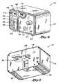
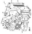
Figure 1 is a pneumatic diagram of a ventilation system and pressure driver such as may be used for providing CPAP therapy to a patient;Figure 2 is a perspective front view of the pressure driver as may be used in the ventilation system for providing pressurized gas to the patient;Figure 3 is a perspective view of a rear portion of the pressure driver and illustrating an air port and an oxygen port which may collectively comprise a gas source for the ventilation system;Figure 4 is a perspective view of the pressure driver and illustrating an oxygen mixer for mixing ambient air and oxygen delivered by the air and oxygen ports, respectively;Figure 5 is a perspective aft view of the pressure driver and illustrating the various components that make up the pressure driver; andFigure 6 is a cross-sectional top view of the pressure driver illustrating various components thereof including, but not limited to, a battery pack, the air and oxygen ports, the oxygen mixer, a mixture control, an oxygen sensor, a mixture indicator and an inspiratory flow control valve.- Referring now to the drawings wherein the showings are for purposes of illustrating preferred embodiments of the present invention only, and not for purposes of limiting the same,
Figure 1 is a pneumatic diagram of a ventilation system as may be used for providing continuous positive airway pressure (CPAP) therapy to a patient. The ventilation system includes apressure driver 10 for providing pressurized gas to the patient. Although not shown inFigure 1 , the ventilation system may also include a flow generator or micro generator (not shown) patient circuit such as that which is disclosed inU.S. Patent Application No. 11/241,303, filed September 30, 2005 by Duquette et al. - As was mentioned above, the flow generator may be useful in facilitating inhalation and exhalation during CPAP treatment. In this regard, the
pressure driver 10 may be utilized in conjunction with the flow generator to provide a stable CPAP pressure in order to facilitate restoration of functional residual capacity (FRC) of the patient and to correct hypoxemia. Such flow generator is typically installed at the patient interface and may include a nose piece member having D-shaped nostril-engaging stems that anatomically conform to the patient's nostrils such as is disclosed and shown inU.S. Patent Application Publication No. 2003/0200970, filed October 30, 2003 by Stenzler et al. and which is entitled, Infant Breathing Assist Apparatus. As can also be seen inFigure 1 , the ventilation system may optionally include anexhalation system 84 to facilitate removal of exhalation gases from the patient. - Importantly, the pneumatic system includes a closed
loop control system 72 for thepressure driver 10 in order to maintain pressure at the patient. In this regard, thepressure driver 10 utilizes patient pressure for feedback to an inspirationflow control valve 52 in order to provide accurate and stable positive airway pressure. The inspirationflow control valve 52 is operative to open and close in response to patient pressure measurement in order to produce a desired pressure at the patient. - As can be seen in the pneumatic diagram of
Figure 1 , thegas source 26 is preferably operative to deliver a mixture of oxygen and air to the inspirationflow control valve 52. The air may be drawn by thegas source 26 from ambient atmosphere after which the air may be mixed with oxygen and/or other gases or combinations thereof for delivery to the patient. The air may also be drawn from the environment or from a compressed air tank or other suitable source. Likewise, the oxygen may be drawn from an oxygen tank or other suitable source. It is also contemplated that oxygen may be delivered downstream of thegas source 26 such as downstream of the inspirationflow control valve 52 or at the patient interface and may be regulated to control the concentration of oxygen delivered to the patient. - As can be seen in
Figure 1 , thepatient pressure sensor 62 may be disposed adjacent a patient wye. Thepatient pressure sensor 62 may be configured as a pressure transducer or other suitable instrument for measuring pressure in gas delivered to the patient. The inspirationflow control valve 52 is generally located between thegas source 26 and the patient and is operative to open and close in response to patient pressure measurements. In this regard, thepatient pressure sensor 62 and the inspirationflow control valve 52 comprise the closedloop control system 72. The closedloop control system 72 may further include a processor or microprocessor adapted to generate a control system command in response to the patient pressure measurements. Such control system command is then delivered to the inspirationflow control valve 52 which is operative to produce the desired pressure at the patient. User input capability and memory capability may be included in the control system, as described in greater detail below. - As can be seen in
Figure 1 , the pneumatic circuit may further include aproximal pressure sensor 60 which may be disposed internally to thepressure driver 10 and which is preferably operative to detect leakage in the ventilation system. Like thepatient pressure sensor 62. theproximal pressure sensor 60 may be configured as a pressure transducer and is preferably operative to continuously sample pressure in the ventilation system for feedback to the closedloop control system 72. In this manner, leakage within the ventilation system or at the patient interface may be detected such that the inspirationflow control valve 52 may make the appropriate corrections such that pressure may be maintained at the patient. - A
pressure regulator 88 is also preferably incorporated into thepressure driver 10. As shown inFig. 1 , thepressure driver 10 is fluidly connected between thegas source 26 and the inspirationflow control valve 52 and is preferably operative to regulate the pressure of gas flowing from thegas source 26 and/or from anoxygen mixer 86 disposed downstream of thegas source 26. Thepressure regulator 88 ensures that a constant source of pressurized gas is made available to the inspirationflow control valve 52. - As was earlier mentioned, the inspiration
flow control valve 52 is responsive to feedback from thepatient pressure sensor 62 and opens and closes the appropriate amount in accordance with a preprogrammed or manually-set desired patient pressure level. The inspirationflow control valve 52 may be configured as a voltage sensitive orifice (VSO) valve although alterative valve configurations may be used for the inspirationflow control valve 52. In the VSO configurations, the inspirationflow control valve 52 is a solenoid valve that is responsive to open and close in proportion to DC current or pulse width modulation under the closedloop control system 72. In this manner, the VSO valve may control the flow of pressurized gas in the pneumatic circuit in proportion to input current. - As was earlier mentioned, the
pressure driver 10 may include theoxygen mixer 86 which is operative to provide a mixture of ambient air and oxygen to the patient. In this regard, the pneumatic circuit preferably may include anoxygen sensor 46 disposed downstream of the inspirationflow control valve 52. Theoxygen sensor 46 is preferably operative to measure the concentration of oxygen in the pressurized gas that is being delivered to the patient. The oxygen concentration may be selectively adjusted via anoxygen mixture control 44 mounted on thepressure driver 10, as will be described below in thepressure driver 10 hardware description. In CPAP treatment, themixture control 44 may be periodically adjusted in order to gradually reduce patient dependency upon the oxygen concentration in the pressurized gas as the patient acquires normal respiratory function. Themixture control 44 may be configured to provide oxygenated gas at any percentage ranging from zero percent to 100 percent as measured by theoxygen sensor 46. - An
inspiratory check valve 56 may be further included in the pneumatic circuit as shown inFigure 1 . Theinspiratory check valve 56 may be interposed between the patient and the inspirationflow control valve 52 and is preferably operative to block the flow of pressurized gas in a direction from the patient toward the inspirationflow control valve 52. In this regard, theinspiratory check valve 56 allows flow in a single direction only (i.e., toward the patient). As shown in the pneumatic circuit, asafety valve 58 may be located between the patient andinspiratory check valve 56. Thesafety valve 58 cooperates with theinspiratory check valve 56 to provide a secondary safety feature for ventilation of the patient in the event of a malfunction of the ventilation system such that the patient may receive appropriate ventilation despite a malfunction of the ventilation system. - As was earlier mentioned, the closed
loop control system 72 for thepressure driver 10 provides accurate and stable pressure at the patient airway despite changes in the pneumatic circuit or changes at the patient circuit. Signals from thepatient pressure sensor 62 may also be converted to a visual and/or audible format for pressure indication such that a clinician may observe and monitor actual patient pressure. In this regard, a desiredpatient pressure indicator 66 and an actualpatient pressure indicator 68 may be provided in digital readout format. A patient pressurecontrol 64 mechanism may further be included with the hardware configuration of thepressure driver 10 as a means to allow selective adjustment of the desired patient pressure. More specifically, the desired patient pressure may be selectively manipulated via a pair of push buttons mounted on ahousing 12 of thepressure driver 10. - Referring still to the pneumatic diagram of Figure 13 the ventilation system further includes an
exhalation system 84 for facilitating discharge of exhalation gases from the patient upon initiation by the patient. As can be seen, theexhalation system 84 may interconnect the patient to thegas source 26 at a location downstream of thepressure regulator 88. In this regard, pressurized gas is provided to theexhalation system 84 to facilitate removal of exhalation gases. Theexhalation system 84 is arranged in parallel with thepressure driver 10 which delivers inspiration gases to the patient. Theexhalation system 84 includes the required componentry to vent exhalation gases from the patient in a manner which reduces the work of breathing. - More specifically, the
exhalation system 84 includes anexpiratory check valve 78, anexhalation valve 80, adrive venturi 82 and aVSO valve 54. Similar to the operation of theinspiratory check valve 56, theexpiratory check valve 78 allows only one-way flow therethrough. More particularly, theexpiratory check valve 78 is configured to prevent flow of exhalation gases in a direction toward the patient. Theexhalation valve 80 interconnects theexpiratory check valve 78 to the patient and is preferably operative to vent exhalation gases from the patient. Such exhalation gases may be vented to the environment. Thedrive venturi 82 facilitates removal of exhalation gases upon initiation by the patient. Due to its unique geometry, gases readily flow from theexhalation valve 80 via thedrive venturi 82. - Upon initiation of the exhalation phase by the patient, the
drive venturi 82 promotes the exhaustion of exhalation gases out of the patient's airway. TheVSO valve 54 is connected to thedrive venturi 82 as shown inFigure 1 and is also connected to thepressure driver 10 between thepressure regulator 88 and the inspirationflow control valve 52. TheVSO valve 54 provides a regulated flow of pressurized gas to thedrive venturi 82 for removal of exhalation gases in order to reduce the work of breathing. Also shown in the pneumatic circuit ofFigure 1 is an optional blendedgas port 50 extending from theoxygen mixer 86. Such blended gasport 50 may be fluidly connected to supply pressurized gas to aclosed exhalation valve 80 system such as may be used for dual-limb patient circuits. - Referring now to
Figures 2-6 , shown is an exemplary embodiment of a hardware configuration for thepressure driver 10 as utilized in the ventilation system shown inFigure 1 . Thepressure driver 10 may include ahousing 12 which may include a pair offeet 22 for supporting thepressure driver 10 on a countertop, table or stand. Although shown as being generally orthogonally shaped, thehousing 12 may be configured in a wide variety of shapes, sizes and alternative configurations. Thehousing 12 may have a mountingplate 20 and front and back portions with the back portion serving as means for connection of theair port 32 andoxygen port 28. The back portion may further include aback plate 18 to which a manifold may be mounted for receiving the air andoxygen ports - A
power supply port 38 may be disposed or mounted on theback plate 18. Thepower supply port 38 may be configured to supply power to thepressure driver 10 and/or to charge aninternal battery 36 orbattery pack 34. As can be seen inFigure 3 , thepressure driver 10 may further include afilter 30 which may be fluidly connected to theoxygen port 28 and which is preferably operative to filter oxygen flowing therefrom to a predetermined purity level such as, for example, to 0.5 microns. Thefilter 30 can also be seen inFigure 5 and is disposed adjacent to the manifold through which oxygen flows. Once filtered, the oxygen is then provided to theoxygen mixer 86 also visible inFigure 5 . - Air from the
air port 32 also flows to theoxygen mixer 86 whereupon the desired concentration of oxygen is mixed therewith and provided to the inspirationflow control valve 52 according to a predetermined or user-set concentration level. Such oxygen concentration is regulated by manipulation of themixture control 44 which is shown as a rotatable knob extending from aface plate 16 on a front side of thehousing 12. - As was earlier mentioned, the concentration of oxygen can be provided in any range from zero percent to 100 percent. A
mixture indicator 48 is also provided on theface plate 16 of thehousing 12 of thepressure driver 10. Illustrated in the figures as a three-digit digital readout device, themixture indicator 48 may be configured in any suitable configuration for displaying the oxygen concentration of the pressurized gas as measured by theoxygen sensor 46. - The
pressure driver 10 further includes thepatient pressure sensor 62 which is preferably disposed adjacent to or contained within thehousing 12. Thepatient pressure sensor 62 is operative to measure pressure at the patient for feedback to the inspirationflow control valve 52. The inspirationflow control valve 52 can be seen mounted within thehousing 12 as shown inFigures 5 and6 and, as was earlier mentioned, is operative to open and close in response to feedback on the patient pressure measurement in an aspect of the present invention, thepatient pressure sensor 62 is preferably disposed at the patient interface device. - The inspiration
flow control valve 52 and thepatient pressure sensor 62 are defined in the present application as comprising the closedloop control system 72. The closedloop control system 72 may include a processor capable of receiving input from thepatient pressure sensor 62 and, based on signals produced thereby, perform necessary memory and processing functions in order to control the actuating parameters of the inspirationflow control valve 52. As was also earlier mentioned, the inspirationflow control valve 52 may be implemented as a VSO valve although other valves types are contemplated. - Also disposed on the front portion of the
pressure driver 10 is the desiredpatient pressure indicator 66 and actualpatient pressure indicator 68. Similar to the configuration of themixture indicator 48, the desiredpatient pressure indicator 66 may also be configured as a digital readout or digital display such as via light- emitting-diode (LED) type devices or other suitable display devices. Manipulation of the desired patient pressure may be effectuated through the use of apatient pressure control 64 which is also preferably disposed on the front portion of thepressure driver 10. - As shown in
Figure 2 ,patient pressure control 64 may be configured as a pair of buttons shaped as arrows and which allow the user to increase or decrease the desired patient pressure. Alternatively, various other control means may be provided for thepatient pressure control 64. The actualpatient pressure indicator 68 may be configured as a bar graph manometer formed as a vertical array of LED's to indicate actual patient pressure as measured by thepatient pressure sensor 62 as measured in cm. of H2O. However, a digital readout or other suitable user interface is contemplated for providing an indication of the actual patient pressure. Mounted at the extreme upper and lower ends of the bar graph manometer for the actual patient
pressure, a pair of high andlow pressure alarm 42 settings (e.g., LED's) are preferably configured to respond to patient pressure measurement outside of a predetermined range as measured at the patient by thepatient pressure sensor 62. - Activation of the
pressure driver 10 may be facilitated by means of apower switch 74 which may be mounted on a front portion of thepressure driver 10. Power may be provided in AC via thepower supply port 38 disposed on the rear portion of thepressure driver 10. As can be seen inFigure 6 , thepressure driver 10 may include abattery pack 34 comprised of at least one and, preferably, several batteries to power thepressure driver 10 during intra-hospital transport or ambulatory transport. In addition, thebattery pack 34, which may be rechargeable, may also be configured to provide back-up power in the event of a power outage such that critical care respiratory support is provided at all times. - In order to provide status on power, a
power indicator 40 display device may be disposed on a front portion of thepressure driver 10. Thepower indicator 40 is preferably configured to provide a readout regarding battery power level and other power conditions. For example, thepower indicator 40 may comprise an array of LED bars and/or digital displays configured to indicatepower 40 "On/Off" conditions as well as available battery charge and/or battery power levels. Furthermore, provisions for indicating whether power is provided via an AC source or from thebattery pack 34 may also be available on thepressure driver 10 such as on the front potion thereof. - Each of the above-mentioned control and display mechanisms may be further provided with any variety of visual and/or audible alarm capabilities. For example, a high or low patient pressure reading as monitored by the
patient pressure sensor 62 may activate a visual and/oraudible alarm 42. Likewise, loss of battery power and/or AC power or a low power level condition may be indicated by means of an audible orvisual alarm 42. It is also contemplated thatsuch alarm 42 mechanisms are configured to be re-settable. - As shown in the figures, it is contemplated that the above-mentioned regulatory and monitoring devices (i.e.,
mixture indicator 48, desiredpatient pressure indicator 66 and actual patient pressure indicator 68) may be mounted on a printedcircuit board 24 disposed on the front side of thehousing 12 of thepressure driver 10. Likewise,patient supply port 70 andexhalation system port 76 may be mounted on the faceplate on the front portion of thehousing 12 of thepressure driver 10. - It should be pointed out that the above-disclosed structural arrangement of the various pressure and oxygen regulatory and monitoring devices may be arranged in any suitable form other than that which is shown and described herein. The
housing 12 itself may include adivider 14 member which may generally divide an internal compartment defined by thehousing 12. Thedivider 14 may separate electrical components (i.e.,battery pack 34, printedcircuit board 24 withmixture indicator 48, desiredpatient pressure indicator 66 and actualpatient pressure indicators 68 mounted thereon) from pneumatic elements such as themixture control 44,patient supply port 70 andexhalation system port 76. - Referring to
Figures 1-6 , the operation of thepressure driver 10 will now be described.. Upon fluid interconnection of thepatient supply port 70 to the patient circuit such as via the appropriate patient interface, and with optional interconnection of theexhalation system 84 to thepressure driver 10 via theexhalation system port 76, thepressure driver 10 may be activated with thepower switch 74. Oxygen may be provided via an oxygen tank or other suitable oxygen source through theoxygen port 28 at the rear portion of thehousing 12. - The oxygen may be passed through the
filter 30 shown inFigures 3 and5 prior to delivery to theoxygen mixer 86. Air may be drawn into theair port 32 and is delivered to theoxygen mixer 86. The user may regulate the desired oxygen concentration by manipulating (i.e., rotating) themixture control 44 located on the front portion of thepressure driver 10. The mixture of pressurized gas is then delivered to thepressure regulator 88 which limits the maximum pressure thereof. The pressurized gas is then provided to the inspirationflow control valve 52 which operates in response to user input regarding patient pressure. - As was earlier mentioned, the
patient pressure control 64 may allow for selective manipulation of the pressure in the pneumatic circuit. Thepatient pressure sensor 62 continuously monitors pressure at the patient and delivers signals representative thereof to the inspirationflow control valve 52 which then opens and closes in order to achieve the desired patient pressure. Theinspiratory check valve 56 prevents the flow of the gas in a direction from the patient to the inspirationflow control valve 52 and works in combination with thesafety valve 58 as a secondary safety feature during patient ventilation. The proximal pressure transducer senses and detects pressure losses such as due to leakage at the patient interface or at other locations within the pneumatic circuit and sends representative signals thereof to the controller (i.e., to the control system) for compensating purposes. - The
optional exhalation system 84 may be supplied with pressurized gas from thepressure regulator 88 and works in conjunction with the VSO valve and driveventuri 82 to facilitate removal of the patient's exhalation gases through the exhalation valve. Theexpiratory check valve 78 is disposed between the exhalation valve and the patient and prevents flow from the exhalation valve back to the patient. User input regarding desired patient pressure may be effectuated by manipulating the pair of buttons as was earlier mentioned. Furthermore, oxygen concentration in the gas delivered to the patient may be regulated by manipulating (i.e., rotating) themixture control 44 on the front portion of thepressure driver 10. - Visual and/or audible indications of the actual and desired patient pressures may be provided via the actual
patient pressure indicator 68 and desiredpatient pressure indicator 66 which may be configured in any suitable form including the LED readouts mentioned above. It is contemplated that other input and output capability (e.g., memory capability and data input capability) may be incorporated into the control system of thepressure driver 10. Power status of thepressure driver 10 may likewise be communicated to a user via a power level andalarm 42 provisions as mentioned above. Advantageously, the incorporation of thebattery 36 and/orbattery pack 34 allows for intra-hospital transport or for emergency back-up power in the event of a power outage. - Additional modifications and improvements of the present invention may also be apparent to those of ordinary skill in the art. Thus, the particular combination of parts described and illustrated herein is intended to represent only certain embodiments of the present invention. .
Claims (15)
- A ventilation system (90) for ventilating a patient comprising a pressure driver (10), the pressure driver (10) comprising:a gas source (26);a patient pressure sensor (62) disposed at a patient interface device and operative to measure pressure at the patient; andan inspiration flow control valve (52) interposed between the gas source (26) and the patient interface device and being operative to open and close in response to patient pressure measurements;the ventilation system (90) beingcharacterized in that it further comprises an exhalation system (84) interconnecting the patient to the gas source (26) and being arranged in parallel with the inspiration flow control valve (52), the exhalation system (84) being operative to vent exhalation gases from the patient, wherein the exhalation system (84) includes an exhalation valve (80) and an expiratory check valve (78) interconnecting the exhalation valve (80) to the patient, the exhalation valve (80) configured to vent exhalation gases from the patient;wherein the exhalation system (84) includes a proportional solenoid valve (54) interposed between the pressure driver (10) and the patient interface device, and a drive venturi (82) interposed between the proportional solenoid valve (54) and the exhalation valve (80), the drive venturi (82) being operative to facilitate the flow of gas, wherein the flow control valve (54) provides a regulated flow of pressurized gas to the drive venturi (82) for removal of
- The ventilation system of Claim 1 wherein:the patient pressure sensor (62) and the inspiration flow control valve (52) comprise a closed loop control system operative to generate a control system command in response to the patient pressure measurements and;the inspiration flow control valve (52) is operative to open and close in response to the control system command for producing a desired pressure at the patient.
- The ventilation system of Claim 1 wherein the patient pressure sensor (62) is configured as a pressure transducer, and/or wherein the inspiration flow control valve (52) is configured as a solenoid valve.
- The ventilation system of Claim 1 wherein the gas source (26) is operative to deliver a mixture of oxygen and air to the inspiration flow control valve (52) and preferably includes an oxygen sensor operative to measure the oxygen concentration in the gas delivered to the patient.
- The ventilation system of Claim 1 further comprising a safety valve (58) interposed between the patient interface device and the inspiration flow control valve (52).
- The ventilation system of Claim 1, wherein the proportional solenoid valve (54) is responsive to open and close in proportion to one of either a current or a pulse width modulation.
- The ventilation system of Claim 1 wherein the expiratory check valve (78) is operative to prevent flow in a direction from the exhalation valve (80) to the patient.
- The ventilation system of Claim 1, wherein the patient pressure sensor (62) is disposed adjacent a patient wye port.
- The ventilation system of Claim 1 wherein the ventilation system is a continuous positive airway pressure ventilation system for ventilating a patient, the pressure driver (10) comprising:a pressure regulator (88) fluidly connected to the gas source (26) and being operative to regulate the pressure of gas from the gas source (26);a closed loop control system comprising:the inspiration flow control valve (52) and the patient pressure sensor (62), the inspiration flow control valve (52) being fluidly connected between the pressure regulator (88) and the patient interface device; the patient pressure sensor (62) being operative to measure pressure at the patient for feedback to the inspiration flow control valve (52).
- The ventilation system of Claim 2 or 9 wherein the control system further includes a proximal pressure sensor (60) interposed between the patient interface device and the inspiration flow control valve (52), the proximal pressure sensor (60) being operative to detect leakage at the patient.
- The ventilation system of Claim 9 wherein the gas source (26) includes an oxygen mixer (86) configured to provide a mixture of ambient air and oxygen to the patient and/or wherein a safety valve (58) is interposed between the patient interface device and the inspiration flow control valve (52) and being operative to limit the pressure of gas delivered to the patient.
- The ventilation system of Claim 5 or 9 wherein the pressure driver (10) further comprises an inspiratory check valve (56) interposed between the patient interface device and the inspiration flow control valve (52) and being operative to prevent flow in a direction from the patient to the inspiration flow control valve (52).
- The ventilation system of Claim 9 wherein:the expiratory check valve (78) is configured to prevent flow in a direction toward the patient;the proportional solenoid valve (54) is connected to the drive venturi (82) and is interconnected between the pressure regulator (88) and the inspiration flow control valve (52), the proportional solenoid valve (54) being operative to regulate the flow of gases from the exhalation valve (80).
- The ventilation system of Claim 1, wherein the pressure driver (10) further comprises:a housing (12), wherein the gas source (26) comprises an oxygen port (28) and an air port (32) and is mounted on the housing (12), the patient pressure sensor (62) is disposed on the housing (12);a pressure regulator (88) disposed on the housing (12) and fluidly connected to the gas source (26) and being operative to regulate the pressure of gas flowing therefrom, wherein the inspiration flow control valve (52) is disposed on the housing (12) and operates to produce a desired pressure at the patient;a mixture control (44) configured to allow for selective adjustment of the oxygen concentration delivered to the patient;an oxygen mixer (86) connected to the gas source and being operative to deliver a mixture of oxygen and air to the inspiration flow control valve in response to a setting of the mixture control (44); andan oxygen sensor (46) operative to measure the oxygen concentration in the gas provided to the patient.
- A ventilation system of Claim 14 wherein the pressure driver (10) further comprises at least one of a filter (30) connected to the oxygen port and being operative to filter oxygen flowing therefrom; a battery pack (34) operative to power the pressure driver; a power supply port (38) mounted on the housing (12) and being connectable to an exterior power source for powering the pressure driver; and a desired patient pressure indicator (66) operative to indicate the desired pressure of gas delivered to the patient; an actual patient pressure indicator (68) operative to indicate an actual patient pressure of gas delivered to the patient as measured by the patient pressure sensor.
Applications Claiming Priority (2)
| Application Number | Priority Date | Filing Date | Title |
|---|---|---|---|
| US11/358,420US7509957B2 (en) | 2006-02-21 | 2006-02-21 | Hardware configuration for pressure driver |
| PCT/US2006/048083WO2007136411A2 (en) | 2006-02-21 | 2006-12-15 | Hardware configuration for pressure driver |
Publications (3)
| Publication Number | Publication Date |
|---|---|
| EP1986723A2 EP1986723A2 (en) | 2008-11-05 |
| EP1986723A4 EP1986723A4 (en) | 2011-11-23 |
| EP1986723B1true EP1986723B1 (en) | 2016-08-24 |
Family
ID=38426912
Family Applications (1)
| Application Number | Title | Priority Date | Filing Date |
|---|---|---|---|
| EP06851308.4AActiveEP1986723B1 (en) | 2006-02-21 | 2006-12-15 | Hardware configuration for pressure driver |
Country Status (6)
| Country | Link |
|---|---|
| US (1) | US7509957B2 (en) |
| EP (1) | EP1986723B1 (en) |
| JP (1) | JP4938804B2 (en) |
| CN (1) | CN101437564B (en) |
| AU (1) | AU2006344054B2 (en) |
| WO (1) | WO2007136411A2 (en) |
Families Citing this family (126)
| Publication number | Priority date | Publication date | Assignee | Title |
|---|---|---|---|---|
| US7588033B2 (en) | 2003-06-18 | 2009-09-15 | Breathe Technologies, Inc. | Methods, systems and devices for improving ventilation in a lung area |
| FR2858236B1 (en)* | 2003-07-29 | 2006-04-28 | Airox | DEVICE AND METHOD FOR SUPPLYING RESPIRATORY GAS IN PRESSURE OR VOLUME |
| CN1905917B (en) | 2003-08-18 | 2011-08-03 | 门罗生命公司 | Method and device for non-invasive ventilation with nasal interface |
| EP1722635B1 (en)* | 2004-02-23 | 2015-11-04 | SSS Acquisition, LLC | Feeds containing hop acids and uses thereof as supplements in animal feeds |
| JP2009508645A (en) | 2005-09-20 | 2009-03-05 | ルッツ フレイテッグ, | System, method and apparatus for assisting patient breathing |
| NZ552009A (en)* | 2006-01-24 | 2007-10-26 | Devx Tech Ip Ltd | Hypoxic training apparatus with gas supply from primary, secondary and tertiary sources |
| US8960194B2 (en)* | 2006-02-23 | 2015-02-24 | Spacelabs Healthcare Llc | Ventilator for rapid response to respiratory disease conditions |
| WO2007101124A2 (en)* | 2006-02-23 | 2007-09-07 | Spacelabs Healthcare | Ventilator for rapid response to respiratory disease conditions |
| JP5191005B2 (en) | 2006-05-18 | 2013-04-24 | ブリーズ テクノロジーズ, インコーポレイテッド | Method and device for tracheostomy |
| US20070273216A1 (en)* | 2006-05-24 | 2007-11-29 | Farbarik John M | Systems and Methods for Reducing Power Losses in a Medical Device |
| EP2068992B1 (en) | 2006-08-03 | 2016-10-05 | Breathe Technologies, Inc. | Devices for minimally invasive respiratory support |
| US20080190421A1 (en)* | 2007-02-12 | 2008-08-14 | Darryl Zitting | Venturi apparatus with incorporated flow metering device |
| WO2008144589A1 (en) | 2007-05-18 | 2008-11-27 | Breathe Technologies, Inc. | Methods and devices for sensing respiration and providing ventilation therapy |
| DE102007031043B4 (en)* | 2007-07-04 | 2014-04-10 | B/E Aerospace Systems Gmbh | Oxygen supply means |
| EP2200686A4 (en) | 2007-09-26 | 2017-11-01 | Breathe Technologies, Inc. | Methods and devices for providing inspiratory and expiratory flow relief during ventilation therapy |
| EP2203206A4 (en) | 2007-09-26 | 2017-12-06 | Breathe Technologies, Inc. | Methods and devices for treating sleep apnea |
| BRPI0906938A2 (en)* | 2008-01-11 | 2015-07-28 | Koninkl Philips Electronics Nv | Ventilator, and method and system configured to provide a dispensing gas flow to an individual's airway |
| US20090205661A1 (en)* | 2008-02-20 | 2009-08-20 | Nellcor Puritan Bennett Llc | Systems and methods for extended volume range ventilation |
| US8267085B2 (en)* | 2009-03-20 | 2012-09-18 | Nellcor Puritan Bennett Llc | Leak-compensated proportional assist ventilation |
| US10207069B2 (en) | 2008-03-31 | 2019-02-19 | Covidien Lp | System and method for determining ventilator leakage during stable periods within a breath |
| US8746248B2 (en) | 2008-03-31 | 2014-06-10 | Covidien Lp | Determination of patient circuit disconnect in leak-compensated ventilatory support |
| US8272380B2 (en)* | 2008-03-31 | 2012-09-25 | Nellcor Puritan Bennett, Llc | Leak-compensated pressure triggering in medical ventilators |
| US8776793B2 (en) | 2008-04-18 | 2014-07-15 | Breathe Technologies, Inc. | Methods and devices for sensing respiration and controlling ventilator functions |
| WO2009129506A1 (en) | 2008-04-18 | 2009-10-22 | Breathe Technologies, Inc. | Methods and devices for sensing respiration and controlling ventilator functions |
| US8457706B2 (en)* | 2008-05-16 | 2013-06-04 | Covidien Lp | Estimation of a physiological parameter using a neural network |
| WO2009149357A1 (en) | 2008-06-06 | 2009-12-10 | Nellcor Puritan Bennett Llc | Systems and methods for ventilation in proportion to patient effort |
| CN102196837B (en) | 2008-08-22 | 2015-09-09 | 呼吸科技公司 | Methods and devices for providing mechanical ventilation utilizing an open airway interface |
| WO2010028150A1 (en) | 2008-09-04 | 2010-03-11 | Nellcor Puritan Bennett Llc | Ventilator with controlled purge function |
| US8551006B2 (en)* | 2008-09-17 | 2013-10-08 | Covidien Lp | Method for determining hemodynamic effects |
| US20100071695A1 (en)* | 2008-09-23 | 2010-03-25 | Ron Thiessen | Patient wye with flow transducer |
| US8181648B2 (en) | 2008-09-26 | 2012-05-22 | Nellcor Puritan Bennett Llc | Systems and methods for managing pressure in a breathing assistance system |
| US8113062B2 (en) | 2008-09-30 | 2012-02-14 | Nellcor Puritan Bennett Llc | Tilt sensor for use with proximal flow sensing device |
| US8393323B2 (en) | 2008-09-30 | 2013-03-12 | Covidien Lp | Supplemental gas safety system for a breathing assistance system |
| US8302602B2 (en) | 2008-09-30 | 2012-11-06 | Nellcor Puritan Bennett Llc | Breathing assistance system with multiple pressure sensors |
| US10252020B2 (en) | 2008-10-01 | 2019-04-09 | Breathe Technologies, Inc. | Ventilator with biofeedback monitoring and control for improving patient activity and health |
| US9314579B2 (en)* | 2008-10-17 | 2016-04-19 | Koninklijke Philips N.V. | Porting block for a medical ventilator |
| BRPI0914035A2 (en) | 2008-10-17 | 2015-11-03 | Koninkl Philips Electronics Nv | ventilator and method for ventilating a patient using a ventilator |
| US8082312B2 (en) | 2008-12-12 | 2011-12-20 | Event Medical, Inc. | System and method for communicating over a network with a medical device |
| US9132250B2 (en) | 2009-09-03 | 2015-09-15 | Breathe Technologies, Inc. | Methods, systems and devices for non-invasive ventilation including a non-sealing ventilation interface with an entrainment port and/or pressure feature |
| US8434479B2 (en) | 2009-02-27 | 2013-05-07 | Covidien Lp | Flow rate compensation for transient thermal response of hot-wire anemometers |
| US20100218766A1 (en)* | 2009-02-27 | 2010-09-02 | Nellcor Puritan Bennett Llc | Customizable mandatory/spontaneous closed loop mode selection |
| US8424521B2 (en) | 2009-02-27 | 2013-04-23 | Covidien Lp | Leak-compensated respiratory mechanics estimation in medical ventilators |
| US8418691B2 (en)* | 2009-03-20 | 2013-04-16 | Covidien Lp | Leak-compensated pressure regulated volume control ventilation |
| CN111420208B (en) | 2009-04-02 | 2023-07-04 | 呼吸科技公司 | Methods, systems and devices for non-invasive open ventilation using a gas delivery nozzle within an outer tube |
| US9962512B2 (en) | 2009-04-02 | 2018-05-08 | Breathe Technologies, Inc. | Methods, systems and devices for non-invasive ventilation including a non-sealing ventilation interface with a free space nozzle feature |
| WO2010124191A2 (en)* | 2009-04-24 | 2010-10-28 | New York University | System and method for circuits to allow cpap to provide zero pressure |
| US8776790B2 (en)* | 2009-07-16 | 2014-07-15 | Covidien Lp | Wireless, gas flow-powered sensor system for a breathing assistance system |
| US8789529B2 (en) | 2009-08-20 | 2014-07-29 | Covidien Lp | Method for ventilation |
| WO2011029074A1 (en) | 2009-09-03 | 2011-03-10 | Breathe Technologies, Inc. | Methods, systems and devices for non-invasive ventilation including a non-sealing ventilation interface with an entrainment port and/or pressure feature |
| CA2806168C (en)* | 2009-11-17 | 2016-03-29 | Steve Carkner | Automatic flight-safe indicator and method of use for batteries |
| US8439037B2 (en) | 2009-12-01 | 2013-05-14 | Covidien Lp | Exhalation valve assembly with integrated filter and flow sensor |
| US8469030B2 (en) | 2009-12-01 | 2013-06-25 | Covidien Lp | Exhalation valve assembly with selectable contagious/non-contagious latch |
| US8469031B2 (en) | 2009-12-01 | 2013-06-25 | Covidien Lp | Exhalation valve assembly with integrated filter |
| US8439036B2 (en) | 2009-12-01 | 2013-05-14 | Covidien Lp | Exhalation valve assembly with integral flow sensor |
| US8424523B2 (en)* | 2009-12-03 | 2013-04-23 | Covidien Lp | Ventilator respiratory gas accumulator with purge valve |
| US20110146683A1 (en)* | 2009-12-21 | 2011-06-23 | Nellcor Puritan Bennett Llc | Sensor Model |
| US20110146681A1 (en)* | 2009-12-21 | 2011-06-23 | Nellcor Puritan Bennett Llc | Adaptive Flow Sensor Model |
| CN102114293B (en)* | 2009-12-31 | 2014-08-06 | 北京谊安医疗系统股份有限公司 | Control system and method for implementing double horizontal pressures in air passage, breathing machine and anaesthetic machine |
| CN102114291B (en)* | 2009-12-31 | 2014-04-02 | 北京谊安医疗系统股份有限公司 | Control mechanism and method of tidal volume |
| US8171094B2 (en) | 2010-01-19 | 2012-05-01 | Event Medical, Inc. | System and method for communicating over a network with a medical device |
| USD655809S1 (en) | 2010-04-27 | 2012-03-13 | Nellcor Puritan Bennett Llc | Valve body with integral flow meter for an exhalation module |
| USD653749S1 (en) | 2010-04-27 | 2012-02-07 | Nellcor Puritan Bennett Llc | Exhalation module filter body |
| USD655405S1 (en) | 2010-04-27 | 2012-03-06 | Nellcor Puritan Bennett Llc | Filter and valve body for an exhalation module |
| US8676285B2 (en) | 2010-07-28 | 2014-03-18 | Covidien Lp | Methods for validating patient identity |
| CA2807416C (en) | 2010-08-16 | 2019-02-19 | Breathe Technologies, Inc. | Methods, systems and devices using lox to provide ventilatory support |
| US8554298B2 (en) | 2010-09-21 | 2013-10-08 | Cividien LP | Medical ventilator with integrated oximeter data |
| DK2621569T3 (en)* | 2010-09-28 | 2017-07-31 | B&D Electromedical Ltd | treatment Device |
| CA2811423C (en) | 2010-09-30 | 2019-03-12 | Breathe Technologies, Inc. | Methods, systems and devices for humidifying a respiratory tract |
| US8783250B2 (en) | 2011-02-27 | 2014-07-22 | Covidien Lp | Methods and systems for transitory ventilation support |
| US8714154B2 (en) | 2011-03-30 | 2014-05-06 | Covidien Lp | Systems and methods for automatic adjustment of ventilator settings |
| US9629971B2 (en) | 2011-04-29 | 2017-04-25 | Covidien Lp | Methods and systems for exhalation control and trajectory optimization |
| US9789273B2 (en) | 2011-05-13 | 2017-10-17 | Koninklijke Philips N.V. | Sensor and valve integrated into a patient interface |
| US9089657B2 (en) | 2011-10-31 | 2015-07-28 | Covidien Lp | Methods and systems for gating user initiated increases in oxygen concentration during ventilation |
| US9364624B2 (en) | 2011-12-07 | 2016-06-14 | Covidien Lp | Methods and systems for adaptive base flow |
| WO2013098686A1 (en)* | 2011-12-27 | 2013-07-04 | Koninklijke Philips Electronics N.V. | Compensation of breath delivery |
| US9498589B2 (en) | 2011-12-31 | 2016-11-22 | Covidien Lp | Methods and systems for adaptive base flow and leak compensation |
| EP3915620B8 (en) | 2012-04-05 | 2024-03-13 | Fisher & Paykel Healthcare Limited | Respiratory assistance apparatus |
| US9993604B2 (en) | 2012-04-27 | 2018-06-12 | Covidien Lp | Methods and systems for an optimized proportional assist ventilation |
| US9144658B2 (en) | 2012-04-30 | 2015-09-29 | Covidien Lp | Minimizing imposed expiratory resistance of mechanical ventilator by optimizing exhalation valve control |
| US10362967B2 (en) | 2012-07-09 | 2019-07-30 | Covidien Lp | Systems and methods for missed breath detection and indication |
| CN102793959B (en)* | 2012-08-14 | 2015-01-21 | 苏州品诺维新医疗科技有限公司 | Respirator air path system for stabilizing air and oxygen mixed tidal volume |
| US9375542B2 (en) | 2012-11-08 | 2016-06-28 | Covidien Lp | Systems and methods for monitoring, managing, and/or preventing fatigue during ventilation |
| CN103893865B (en)* | 2012-12-26 | 2017-05-31 | 北京谊安医疗系统股份有限公司 | A kind of method of lung ventilator turbine volume controlled ventilation |
| CN103893864B (en)* | 2012-12-26 | 2017-05-24 | 北京谊安医疗系统股份有限公司 | Turbine respirator pressure control ventilation method |
| US9289573B2 (en) | 2012-12-28 | 2016-03-22 | Covidien Lp | Ventilator pressure oscillation filter |
| CN104936643B (en)* | 2013-01-17 | 2018-01-26 | 皇家飞利浦有限公司 | Systems and methods for intrapulmonary percussion ventilation integrated with a ventilator |
| USD731049S1 (en) | 2013-03-05 | 2015-06-02 | Covidien Lp | EVQ housing of an exhalation module |
| USD693001S1 (en) | 2013-03-08 | 2013-11-05 | Covidien Lp | Neonate expiratory filter assembly of an exhalation module |
| USD744095S1 (en) | 2013-03-08 | 2015-11-24 | Covidien Lp | Exhalation module EVQ internal flow sensor |
| USD692556S1 (en) | 2013-03-08 | 2013-10-29 | Covidien Lp | Expiratory filter body of an exhalation module |
| USD731048S1 (en) | 2013-03-08 | 2015-06-02 | Covidien Lp | EVQ diaphragm of an exhalation module |
| USD731065S1 (en) | 2013-03-08 | 2015-06-02 | Covidien Lp | EVQ pressure sensor filter of an exhalation module |
| USD701601S1 (en) | 2013-03-08 | 2014-03-25 | Covidien Lp | Condensate vial of an exhalation module |
| USD736905S1 (en) | 2013-03-08 | 2015-08-18 | Covidien Lp | Exhalation module EVQ housing |
| US9358355B2 (en) | 2013-03-11 | 2016-06-07 | Covidien Lp | Methods and systems for managing a patient move |
| US9950135B2 (en) | 2013-03-15 | 2018-04-24 | Covidien Lp | Maintaining an exhalation valve sensor assembly |
| US9675771B2 (en) | 2013-10-18 | 2017-06-13 | Covidien Lp | Methods and systems for leak estimation |
| WO2015132682A1 (en)* | 2014-03-04 | 2015-09-11 | Koninklijke Philips N.V. | Blending gaz enriched pressure support system and method |
| US11433210B2 (en) | 2014-05-27 | 2022-09-06 | Fisher & Paykel Healthcare Limited | Gases mixing and measuring for a medical device |
| US9808591B2 (en) | 2014-08-15 | 2017-11-07 | Covidien Lp | Methods and systems for breath delivery synchronization |
| US9649468B2 (en) | 2014-09-03 | 2017-05-16 | Fisher & Paykel Healthcare Limited | Respiratory gas humidifier |
| US9950129B2 (en) | 2014-10-27 | 2018-04-24 | Covidien Lp | Ventilation triggering using change-point detection |
| CN104771818B (en)* | 2015-03-02 | 2017-03-01 | 深圳市科曼医疗设备有限公司 | Per nasal pressure generator self-adapting calibration system and method |
| USD775345S1 (en) | 2015-04-10 | 2016-12-27 | Covidien Lp | Ventilator console |
| NZ737589A (en) | 2015-06-24 | 2023-03-31 | Fisher & Paykel Healthcare Ltd | Breathing assistance apparatus |
| AU2016364628B2 (en) | 2015-12-02 | 2022-06-23 | Fisher & Paykel Healthcare Limited | Flow path sensing for flow therapy apparatus |
| EP3386578B1 (en) | 2015-12-11 | 2023-01-25 | Fisher & Paykel Healthcare Limited | Humidification system |
| CN106902427B (en)* | 2015-12-23 | 2019-08-06 | 北京谊安医疗系统股份有限公司 | A kind of electronic flowmeter and the gas path control method using the electronic flowmeter |
| US10675433B2 (en) | 2017-05-25 | 2020-06-09 | MGC Diagnostics Corporation | Solenoid controlled respiratory gas demand valve |
| CN107362426B (en)* | 2017-07-26 | 2020-05-12 | 杨国兰 | Breathing equipment for internal medicine |
| US10792449B2 (en) | 2017-10-03 | 2020-10-06 | Breathe Technologies, Inc. | Patient interface with integrated jet pump |
| AU2018353928B2 (en) | 2017-11-14 | 2019-06-13 | Covidien Lp | Methods and systems for drive pressure spontaneous ventilation |
| WO2019222258A1 (en) | 2018-05-14 | 2019-11-21 | Covidien Lp | Systems and methods for respiratory effort detection utilizing signal distortion |
| US11517691B2 (en) | 2018-09-07 | 2022-12-06 | Covidien Lp | Methods and systems for high pressure controlled ventilation |
| US11752287B2 (en) | 2018-10-03 | 2023-09-12 | Covidien Lp | Systems and methods for automatic cycling or cycling detection |
| JP7314263B2 (en)* | 2018-10-23 | 2023-07-25 | レスメド・プロプライエタリー・リミテッド | System and method for setting up a CPAP system |
| JP7278383B2 (en)* | 2018-12-31 | 2023-05-19 | コーニンクレッカ フィリップス エヌ ヴェ | Method and system for delivering oxygen to a patient |
| US20220211968A1 (en)* | 2019-03-13 | 2022-07-07 | Magnamed Tecnologia Medica S/A | Transportable lung ventilator |
| US11896767B2 (en) | 2020-03-20 | 2024-02-13 | Covidien Lp | Model-driven system integration in medical ventilators |
| WO2021207600A1 (en) | 2020-04-10 | 2021-10-14 | Covidien Lp | Gas mixing system for medical ventilator |
| US11872349B2 (en) | 2020-04-10 | 2024-01-16 | Covidien Lp | Systems and methods for increasing ventilator oxygen concentration |
| US20230218843A1 (en)* | 2020-06-12 | 2023-07-13 | RFDesign Pty Ltd | Medical ventilator |
| CN113769214A (en)* | 2021-08-23 | 2021-12-10 | 河南辉瑞生物医电技术有限公司 | Control system of breathing machine |
| WO2023091535A1 (en)* | 2021-11-17 | 2023-05-25 | Jomoco, Inc. | A sequential, multi-modal, multi-patient mechanical ventilation system |
| WO2025109031A1 (en)* | 2023-11-20 | 2025-05-30 | Meliora Innovation Ltd | Positive airway pressure device |
| CN117695489A (en)* | 2023-12-26 | 2024-03-15 | 深圳市安保医疗科技股份有限公司 | Breathing machine |
Family Cites Families (48)
| Publication number | Priority date | Publication date | Assignee | Title |
|---|---|---|---|---|
| US2985357A (en)* | 1959-03-19 | 1961-05-23 | Bendix Corp | Injectors |
| US4011866A (en)* | 1965-02-05 | 1977-03-15 | Automatic Breathing Apparatus Co., Inc. | Electronically controlled pulmonary ventilator |
| US3630196A (en)* | 1969-08-22 | 1971-12-28 | Bird F M | Manual positive pressure breathing device |
| US3993081A (en)* | 1975-01-23 | 1976-11-23 | Swesco Inc. | Endotracheal tube holder |
| US4018221A (en)* | 1975-09-29 | 1977-04-19 | Thomas Rennie | Support for anesthetic gas delivery hoses and endotracheal tubes |
| US4098290A (en)* | 1976-12-02 | 1978-07-04 | Glenn Joseph G | Miniature intermittent positive pressure breathing valve |
| CA1128826A (en)* | 1978-07-21 | 1982-08-03 | Montreal General Hospital Research Institute | Head-supported oxygen nozzle |
| US4261355A (en)* | 1978-09-25 | 1981-04-14 | Glazener Edwin L | Constant positive pressure breathing apparatus |
| US4281641A (en)* | 1979-01-04 | 1981-08-04 | Heliotropin Engineering Corp. | Solar energy collecting system |
| US4357936A (en)* | 1979-03-05 | 1982-11-09 | Bear Medical Systems, Inc. | Directional thermistor assist sensing |
| US4495946A (en)* | 1981-03-17 | 1985-01-29 | Joseph Lemer | Artificial breathing device |
| DE3119814C2 (en) | 1981-05-19 | 1984-07-26 | Drägerwerk AG, 2400 Lübeck | HFJ ventilator with a controllable breathing gas source and device for generating negative pressure |
| US4457304A (en)* | 1981-12-04 | 1984-07-03 | Minnesota Mining And Manufacturing Company | Self-regulating infant ventilator |
| JPS58112332U (en)* | 1982-01-26 | 1983-08-01 | 泉工医科工業株式会社 | Jet tube for respirator |
| US4459982A (en)* | 1982-09-13 | 1984-07-17 | Bear Medical Systems, Inc. | Servo-controlled demand regulator for respiratory ventilator |
| GB8400618D0 (en)* | 1984-01-11 | 1984-02-15 | Matthews H R | Tracheostomy tube assemblies |
| US4527557A (en)* | 1984-11-01 | 1985-07-09 | Bear Medical Systems, Inc. | Medical ventilator system |
| CS252710B1 (en)* | 1984-12-28 | 1987-10-15 | Ondrej Brychta | Multi-jet generator for high-frequency jet lung-ventilation |
| US4784130A (en)* | 1986-12-04 | 1988-11-15 | The John Bunn Company | Flow controller |
| US4782832A (en)* | 1987-07-30 | 1988-11-08 | Puritan-Bennett Corporation | Nasal puff with adjustable sealing means |
| FR2623404A1 (en)* | 1987-11-19 | 1989-05-26 | Air Liquide | RESPIRATORY ASSISTANCE DEVICE |
| US4919128A (en)* | 1988-08-26 | 1990-04-24 | University Technologies International Inc. | Nasal adaptor device and seal |
| US4915105A (en)* | 1988-10-28 | 1990-04-10 | Lee Tien Chu | Miniature respiratory apparatus |
| SE462614B (en)* | 1988-12-06 | 1990-07-30 | Conny Peder Gunnar Moa | DEVICE TO GENERATE CONTINUOUS POSITIVE AIR PRESSURE IN SPONTANEOUS THROUGH EJECTOR EFFECTS |
| US5113857A (en)* | 1990-08-27 | 1992-05-19 | Stair Dickerman | Breathing gas delivery system and holding clip member therefor |
| US5259376A (en)* | 1990-09-26 | 1993-11-09 | Bales Joseph H | Tracheostomy tube assembly |
| US5542415A (en)* | 1991-05-07 | 1996-08-06 | Infrasonics, Inc. | Apparatus and process for controlling the ventilation of the lungs of a patient |
| US5477852A (en)* | 1991-10-29 | 1995-12-26 | Airways Ltd., Inc. | Nasal positive airway pressure apparatus and method |
| DE19500529C5 (en)* | 1995-01-11 | 2007-11-22 | Dräger Medical AG & Co. KG | Control unit for a ventilator |
| US5598838A (en)* | 1995-04-07 | 1997-02-04 | Healthdyne Technologies, Inc. | Pressure support ventilatory assist system |
| US5499616A (en) | 1995-05-22 | 1996-03-19 | Dresser Industries, Inc. | Crankcase pressure regulation system for an internal combustion engine |
| US6000396A (en)* | 1995-08-17 | 1999-12-14 | University Of Florida | Hybrid microprocessor controlled ventilator unit |
| US6041777A (en)* | 1995-12-01 | 2000-03-28 | Alliance Pharmaceutical Corp. | Methods and apparatus for closed-circuit ventilation therapy |
| US5829428A (en)* | 1996-05-29 | 1998-11-03 | Alliance Pharmaceutical Corp. | Methods and apparatus for reducing the loss of respiratory promoters |
| AUPO163896A0 (en)* | 1996-08-14 | 1996-09-05 | Resmed Limited | Determination of respiratory airflow |
| US5865174A (en)* | 1996-10-29 | 1999-02-02 | The Scott Fetzer Company | Supplemental oxygen delivery apparatus and method |
| US5752510A (en)* | 1996-11-14 | 1998-05-19 | Goldstein; Joseph | Nasal and oral air passageway delivery management apparatus |
| FI105162B (en)* | 1997-02-06 | 2000-06-30 | Instrumentarium Oy | Breathing intensifier and valve coupled to a channel of a breathing intensifier |
| US6131571A (en)* | 1997-04-30 | 2000-10-17 | University Of Florida | Ventilation apparatus and anesthesia delivery system |
| US6076523A (en)* | 1998-01-15 | 2000-06-20 | Nellcor Puritan Bennett | Oxygen blending in a piston ventilator |
| US6152135A (en)* | 1998-10-23 | 2000-11-28 | Pulmonetic Systems, Inc. | Ventilator system |
| DE50015462D1 (en)* | 1999-04-07 | 2009-01-02 | Event Medical Ltd | VENTILATOR |
| US6431172B1 (en)* | 2000-10-20 | 2002-08-13 | Mallinckrodt Inc. | Nasal cannula with inflatable plenum chamber |
| US6571796B2 (en)* | 2001-02-08 | 2003-06-03 | University Of Florida | Tracheal pressure ventilation respiratory system |
| GB0204117D0 (en)* | 2002-02-21 | 2002-04-10 | E M E Electro Medical Equipmen | Breathing device |
| US20030200970A1 (en)* | 2002-04-29 | 2003-10-30 | Alex Stenzler | Infant breathing assist apparatus |
| JP4598357B2 (en)* | 2002-12-17 | 2010-12-15 | 帝人株式会社 | Oxygen supply equipment |
| US7152598B2 (en)* | 2003-06-23 | 2006-12-26 | Invacare Corporation | System and method for providing a breathing gas |
- 2006
- 2006-02-21USUS11/358,420patent/US7509957B2/enactiveActive
- 2006-12-15JPJP2008556309Apatent/JP4938804B2/enactiveActive
- 2006-12-15AUAU2006344054Apatent/AU2006344054B2/enactiveActive
- 2006-12-15WOPCT/US2006/048083patent/WO2007136411A2/enactiveApplication Filing
- 2006-12-15EPEP06851308.4Apatent/EP1986723B1/enactiveActive
- 2006-12-15CNCN200680053195XApatent/CN101437564B/enactiveActive
Also Published As
| Publication number | Publication date |
|---|---|
| AU2006344054B2 (en) | 2013-03-07 |
| WO2007136411A3 (en) | 2008-07-03 |
| CN101437564B (en) | 2012-03-07 |
| AU2006344054A1 (en) | 2007-11-29 |
| US7509957B2 (en) | 2009-03-31 |
| EP1986723A2 (en) | 2008-11-05 |
| JP4938804B2 (en) | 2012-05-23 |
| WO2007136411A2 (en) | 2007-11-29 |
| CN101437564A (en) | 2009-05-20 |
| JP2009527323A (en) | 2009-07-30 |
| US20070193579A1 (en) | 2007-08-23 |
| EP1986723A4 (en) | 2011-11-23 |
Similar Documents
| Publication | Publication Date | Title |
|---|---|---|
| EP1986723B1 (en) | Hardware configuration for pressure driver | |
| CN109069782B (en) | Anesthesia machine and system | |
| US11904098B2 (en) | Additive gas delivery apparatus with backup | |
| EP0916358B1 (en) | Emergency oxygen flowmeter arrangement | |
| US7523752B2 (en) | System and method of administering a pharmaceutical gas to a patient | |
| US5237987A (en) | Human lung ventilator system | |
| CA2706090C (en) | Patient interface assembly for respiratory therapy | |
| US5918597A (en) | Peep control in a piston ventilator | |
| KR101524100B1 (en) | Breathing-gas delivery and sharing system and method | |
| US20110197887A1 (en) | Accessory connection and data synchronication in a ventilator | |
| CN113260401B (en) | Improved continuous positive airway pressure device for neonates | |
| CN116457045A (en) | Breathing assistance apparatus and method | |
| CN115279264B (en) | Method and device for monitoring ventilation of patient | |
| AU2014201260B2 (en) | System and method of administering a pharmaceutical gas to a patient | |
| Street | Ventilation in the intensive care unit | |
| AU2018229527A1 (en) | System and method of administering a pharmaceutical gas to a patient |
Legal Events
| Date | Code | Title | Description |
|---|---|---|---|
| PUAI | Public reference made under article 153(3) epc to a published international application that has entered the european phase | Free format text:ORIGINAL CODE: 0009012 | |
| 17P | Request for examination filed | Effective date:20080911 | |
| AK | Designated contracting states | Kind code of ref document:A2 Designated state(s):AT BE BG CH CY CZ DE DK EE ES FI FR GB GR HU IE IS IT LI LT LU LV MC NL PL PT RO SE SI SK TR | |
| AX | Request for extension of the european patent | Extension state:AL BA HR MK RS | |
| RAP1 | Party data changed (applicant data changed or rights of an application transferred) | Owner name:CARDINAL HEALTH 207, INC. | |
| RAP1 | Party data changed (applicant data changed or rights of an application transferred) | Owner name:CAREFUSION 207, INC. | |
| A4 | Supplementary search report drawn up and despatched | Effective date:20111024 | |
| RIC1 | Information provided on ipc code assigned before grant | Ipc:A61M 16/00 20060101AFI20111019BHEP | |
| DAX | Request for extension of the european patent (deleted) | ||
| 17Q | First examination report despatched | Effective date:20141031 | |
| GRAP | Despatch of communication of intention to grant a patent | Free format text:ORIGINAL CODE: EPIDOSNIGR1 | |
| INTG | Intention to grant announced | Effective date:20160408 | |
| GRAS | Grant fee paid | Free format text:ORIGINAL CODE: EPIDOSNIGR3 | |
| GRAA | (expected) grant | Free format text:ORIGINAL CODE: 0009210 | |
| AK | Designated contracting states | Kind code of ref document:B1 Designated state(s):AT BE BG CH CY CZ DE DK EE ES FI FR GB GR HU IE IS IT LI LT LU LV MC NL PL PT RO SE SI SK TR | |
| REG | Reference to a national code | Ref country code:GB Ref legal event code:FG4D | |
| REG | Reference to a national code | Ref country code:CH Ref legal event code:EP | |
| REG | Reference to a national code | Ref country code:AT Ref legal event code:REF Ref document number:822509 Country of ref document:AT Kind code of ref document:T Effective date:20160915 | |
| REG | Reference to a national code | Ref country code:IE Ref legal event code:FG4D | |
| REG | Reference to a national code | Ref country code:DE Ref legal event code:R096 Ref document number:602006050080 Country of ref document:DE | |
| REG | Reference to a national code | Ref country code:FR Ref legal event code:PLFP Year of fee payment:11 | |
| REG | Reference to a national code | Ref country code:LT Ref legal event code:MG4D | |
| REG | Reference to a national code | Ref country code:NL Ref legal event code:MP Effective date:20160824 | |
| REG | Reference to a national code | Ref country code:AT Ref legal event code:MK05 Ref document number:822509 Country of ref document:AT Kind code of ref document:T Effective date:20160824 | |
| PG25 | Lapsed in a contracting state [announced via postgrant information from national office to epo] | Ref country code:LT Free format text:LAPSE BECAUSE OF FAILURE TO SUBMIT A TRANSLATION OF THE DESCRIPTION OR TO PAY THE FEE WITHIN THE PRESCRIBED TIME-LIMIT Effective date:20160824 Ref country code:FI Free format text:LAPSE BECAUSE OF FAILURE TO SUBMIT A TRANSLATION OF THE DESCRIPTION OR TO PAY THE FEE WITHIN THE PRESCRIBED TIME-LIMIT Effective date:20160824 Ref country code:IT Free format text:LAPSE BECAUSE OF FAILURE TO SUBMIT A TRANSLATION OF THE DESCRIPTION OR TO PAY THE FEE WITHIN THE PRESCRIBED TIME-LIMIT Effective date:20160824 Ref country code:NL Free format text:LAPSE BECAUSE OF FAILURE TO SUBMIT A TRANSLATION OF THE DESCRIPTION OR TO PAY THE FEE WITHIN THE PRESCRIBED TIME-LIMIT Effective date:20160824 | |
| PG25 | Lapsed in a contracting state [announced via postgrant information from national office to epo] | Ref country code:LV Free format text:LAPSE BECAUSE OF FAILURE TO SUBMIT A TRANSLATION OF THE DESCRIPTION OR TO PAY THE FEE WITHIN THE PRESCRIBED TIME-LIMIT Effective date:20160824 Ref country code:GR Free format text:LAPSE BECAUSE OF FAILURE TO SUBMIT A TRANSLATION OF THE DESCRIPTION OR TO PAY THE FEE WITHIN THE PRESCRIBED TIME-LIMIT Effective date:20161125 Ref country code:PT Free format text:LAPSE BECAUSE OF FAILURE TO SUBMIT A TRANSLATION OF THE DESCRIPTION OR TO PAY THE FEE WITHIN THE PRESCRIBED TIME-LIMIT Effective date:20161226 Ref country code:SE Free format text:LAPSE BECAUSE OF FAILURE TO SUBMIT A TRANSLATION OF THE DESCRIPTION OR TO PAY THE FEE WITHIN THE PRESCRIBED TIME-LIMIT Effective date:20160824 Ref country code:AT Free format text:LAPSE BECAUSE OF FAILURE TO SUBMIT A TRANSLATION OF THE DESCRIPTION OR TO PAY THE FEE WITHIN THE PRESCRIBED TIME-LIMIT Effective date:20160824 Ref country code:ES Free format text:LAPSE BECAUSE OF FAILURE TO SUBMIT A TRANSLATION OF THE DESCRIPTION OR TO PAY THE FEE WITHIN THE PRESCRIBED TIME-LIMIT Effective date:20160824 | |
| PG25 | Lapsed in a contracting state [announced via postgrant information from national office to epo] | Ref country code:RO Free format text:LAPSE BECAUSE OF FAILURE TO SUBMIT A TRANSLATION OF THE DESCRIPTION OR TO PAY THE FEE WITHIN THE PRESCRIBED TIME-LIMIT Effective date:20160824 Ref country code:EE Free format text:LAPSE BECAUSE OF FAILURE TO SUBMIT A TRANSLATION OF THE DESCRIPTION OR TO PAY THE FEE WITHIN THE PRESCRIBED TIME-LIMIT Effective date:20160824 | |
| REG | Reference to a national code | Ref country code:DE Ref legal event code:R097 Ref document number:602006050080 Country of ref document:DE | |
| PG25 | Lapsed in a contracting state [announced via postgrant information from national office to epo] | Ref country code:CZ Free format text:LAPSE BECAUSE OF FAILURE TO SUBMIT A TRANSLATION OF THE DESCRIPTION OR TO PAY THE FEE WITHIN THE PRESCRIBED TIME-LIMIT Effective date:20160824 Ref country code:PL Free format text:LAPSE BECAUSE OF FAILURE TO SUBMIT A TRANSLATION OF THE DESCRIPTION OR TO PAY THE FEE WITHIN THE PRESCRIBED TIME-LIMIT Effective date:20160824 Ref country code:BE Free format text:LAPSE BECAUSE OF FAILURE TO SUBMIT A TRANSLATION OF THE DESCRIPTION OR TO PAY THE FEE WITHIN THE PRESCRIBED TIME-LIMIT Effective date:20160824 Ref country code:BG Free format text:LAPSE BECAUSE OF FAILURE TO SUBMIT A TRANSLATION OF THE DESCRIPTION OR TO PAY THE FEE WITHIN THE PRESCRIBED TIME-LIMIT Effective date:20161124 Ref country code:SK Free format text:LAPSE BECAUSE OF FAILURE TO SUBMIT A TRANSLATION OF THE DESCRIPTION OR TO PAY THE FEE WITHIN THE PRESCRIBED TIME-LIMIT Effective date:20160824 Ref country code:DK Free format text:LAPSE BECAUSE OF FAILURE TO SUBMIT A TRANSLATION OF THE DESCRIPTION OR TO PAY THE FEE WITHIN THE PRESCRIBED TIME-LIMIT Effective date:20160824 | |
| PLBE | No opposition filed within time limit | Free format text:ORIGINAL CODE: 0009261 | |
| STAA | Information on the status of an ep patent application or granted ep patent | Free format text:STATUS: NO OPPOSITION FILED WITHIN TIME LIMIT | |
| REG | Reference to a national code | Ref country code:CH Ref legal event code:PL | |
| 26N | No opposition filed | Effective date:20170526 | |
| PG25 | Lapsed in a contracting state [announced via postgrant information from national office to epo] | Ref country code:SI Free format text:LAPSE BECAUSE OF FAILURE TO SUBMIT A TRANSLATION OF THE DESCRIPTION OR TO PAY THE FEE WITHIN THE PRESCRIBED TIME-LIMIT Effective date:20160824 | |
| PG25 | Lapsed in a contracting state [announced via postgrant information from national office to epo] | Ref country code:MC Free format text:LAPSE BECAUSE OF FAILURE TO SUBMIT A TRANSLATION OF THE DESCRIPTION OR TO PAY THE FEE WITHIN THE PRESCRIBED TIME-LIMIT Effective date:20160824 | |
| REG | Reference to a national code | Ref country code:IE Ref legal event code:MM4A | |
| PG25 | Lapsed in a contracting state [announced via postgrant information from national office to epo] | Ref country code:LU Free format text:LAPSE BECAUSE OF NON-PAYMENT OF DUE FEES Effective date:20161215 Ref country code:CH Free format text:LAPSE BECAUSE OF NON-PAYMENT OF DUE FEES Effective date:20161231 Ref country code:LI Free format text:LAPSE BECAUSE OF NON-PAYMENT OF DUE FEES Effective date:20161231 | |
| REG | Reference to a national code | Ref country code:FR Ref legal event code:PLFP Year of fee payment:12 | |
| PG25 | Lapsed in a contracting state [announced via postgrant information from national office to epo] | Ref country code:IE Free format text:LAPSE BECAUSE OF NON-PAYMENT OF DUE FEES Effective date:20161215 | |
| PG25 | Lapsed in a contracting state [announced via postgrant information from national office to epo] | Ref country code:HU Free format text:LAPSE BECAUSE OF FAILURE TO SUBMIT A TRANSLATION OF THE DESCRIPTION OR TO PAY THE FEE WITHIN THE PRESCRIBED TIME-LIMIT; INVALID AB INITIO Effective date:20061215 Ref country code:CY Free format text:LAPSE BECAUSE OF FAILURE TO SUBMIT A TRANSLATION OF THE DESCRIPTION OR TO PAY THE FEE WITHIN THE PRESCRIBED TIME-LIMIT Effective date:20160824 | |
| PG25 | Lapsed in a contracting state [announced via postgrant information from national office to epo] | Ref country code:TR Free format text:LAPSE BECAUSE OF FAILURE TO SUBMIT A TRANSLATION OF THE DESCRIPTION OR TO PAY THE FEE WITHIN THE PRESCRIBED TIME-LIMIT Effective date:20160824 Ref country code:IS Free format text:LAPSE BECAUSE OF FAILURE TO SUBMIT A TRANSLATION OF THE DESCRIPTION OR TO PAY THE FEE WITHIN THE PRESCRIBED TIME-LIMIT Effective date:20160824 | |
| REG | Reference to a national code | Ref country code:GB Ref legal event code:732E Free format text:REGISTERED BETWEEN 20230427 AND 20230503 | |
| P01 | Opt-out of the competence of the unified patent court (upc) registered | Effective date:20230519 | |
| REG | Reference to a national code | Ref country code:DE Ref legal event code:R081 Ref document number:602006050080 Country of ref document:DE Owner name:VYAIRE MEDICAL 211, INC., METTAWA, US Free format text:FORMER OWNER: CAREFUSION 207, INC., SAN DIEGO, CALIF., US | |
| PGFP | Annual fee paid to national office [announced via postgrant information from national office to epo] | Ref country code:GB Payment date:20241217 Year of fee payment:19 | |
| PGFP | Annual fee paid to national office [announced via postgrant information from national office to epo] | Ref country code:FR Payment date:20241226 Year of fee payment:19 | |
| PGFP | Annual fee paid to national office [announced via postgrant information from national office to epo] | Ref country code:DE Payment date:20241227 Year of fee payment:19 |