EP1986568B1 - Methods and devices for restoring blood flow within blocked vasculature - Google Patents
Methods and devices for restoring blood flow within blocked vasculatureDownload PDFInfo
- Publication number
- EP1986568B1 EP1986568B1EP07763224.8AEP07763224AEP1986568B1EP 1986568 B1EP1986568 B1EP 1986568B1EP 07763224 AEP07763224 AEP 07763224AEP 1986568 B1EP1986568 B1EP 1986568B1
- Authority
- EP
- European Patent Office
- Prior art keywords
- connector
- obstruction
- filaments
- far
- microcatheter
- Prior art date
- Legal status (The legal status is an assumption and is not a legal conclusion. Google has not performed a legal analysis and makes no representation as to the accuracy of the status listed.)
- Not-in-force
Links
Images


Classifications
- A—HUMAN NECESSITIES
- A61—MEDICAL OR VETERINARY SCIENCE; HYGIENE
- A61B—DIAGNOSIS; SURGERY; IDENTIFICATION
- A61B17/00—Surgical instruments, devices or methods
- A61B17/22—Implements for squeezing-off ulcers or the like on inner organs of the body; Implements for scraping-out cavities of body organs, e.g. bones; for invasive removal or destruction of calculus using mechanical vibrations; for removing obstructions in blood vessels, not otherwise provided for
- A61B17/221—Gripping devices in the form of loops or baskets for gripping calculi or similar types of obstructions
- A—HUMAN NECESSITIES
- A61—MEDICAL OR VETERINARY SCIENCE; HYGIENE
- A61B—DIAGNOSIS; SURGERY; IDENTIFICATION
- A61B17/00—Surgical instruments, devices or methods
- A61B17/22—Implements for squeezing-off ulcers or the like on inner organs of the body; Implements for scraping-out cavities of body organs, e.g. bones; for invasive removal or destruction of calculus using mechanical vibrations; for removing obstructions in blood vessels, not otherwise provided for
- A61B17/22004—Implements for squeezing-off ulcers or the like on inner organs of the body; Implements for scraping-out cavities of body organs, e.g. bones; for invasive removal or destruction of calculus using mechanical vibrations; for removing obstructions in blood vessels, not otherwise provided for using mechanical vibrations, e.g. ultrasonic shock waves
- A61B17/22012—Implements for squeezing-off ulcers or the like on inner organs of the body; Implements for scraping-out cavities of body organs, e.g. bones; for invasive removal or destruction of calculus using mechanical vibrations; for removing obstructions in blood vessels, not otherwise provided for using mechanical vibrations, e.g. ultrasonic shock waves in direct contact with, or very close to, the obstruction or concrement
- A—HUMAN NECESSITIES
- A61—MEDICAL OR VETERINARY SCIENCE; HYGIENE
- A61B—DIAGNOSIS; SURGERY; IDENTIFICATION
- A61B17/00—Surgical instruments, devices or methods
- A61B17/32—Surgical cutting instruments
- A61B17/3205—Excision instruments
- A61B17/3207—Atherectomy devices working by cutting or abrading; Similar devices specially adapted for non-vascular obstructions
- A61B17/320725—Atherectomy devices working by cutting or abrading; Similar devices specially adapted for non-vascular obstructions with radially expandable cutting or abrading elements
- A—HUMAN NECESSITIES
- A61—MEDICAL OR VETERINARY SCIENCE; HYGIENE
- A61B—DIAGNOSIS; SURGERY; IDENTIFICATION
- A61B17/00—Surgical instruments, devices or methods
- A61B17/32—Surgical cutting instruments
- A61B17/3205—Excision instruments
- A61B17/32056—Surgical snare instruments
- A—HUMAN NECESSITIES
- A61—MEDICAL OR VETERINARY SCIENCE; HYGIENE
- A61B—DIAGNOSIS; SURGERY; IDENTIFICATION
- A61B17/00—Surgical instruments, devices or methods
- A61B2017/00743—Type of operation; Specification of treatment sites
- A61B2017/00778—Operations on blood vessels
- A—HUMAN NECESSITIES
- A61—MEDICAL OR VETERINARY SCIENCE; HYGIENE
- A61B—DIAGNOSIS; SURGERY; IDENTIFICATION
- A61B17/00—Surgical instruments, devices or methods
- A61B2017/00831—Material properties
- A61B2017/00853—Material properties low friction, hydrophobic and corrosion-resistant fluorocarbon resin coating (ptf, ptfe, polytetrafluoroethylene)
- A—HUMAN NECESSITIES
- A61—MEDICAL OR VETERINARY SCIENCE; HYGIENE
- A61B—DIAGNOSIS; SURGERY; IDENTIFICATION
- A61B17/00—Surgical instruments, devices or methods
- A61B2017/00831—Material properties
- A61B2017/00862—Material properties elastic or resilient
- A—HUMAN NECESSITIES
- A61—MEDICAL OR VETERINARY SCIENCE; HYGIENE
- A61B—DIAGNOSIS; SURGERY; IDENTIFICATION
- A61B17/00—Surgical instruments, devices or methods
- A61B2017/00831—Material properties
- A61B2017/00867—Material properties shape memory effect
- A—HUMAN NECESSITIES
- A61—MEDICAL OR VETERINARY SCIENCE; HYGIENE
- A61B—DIAGNOSIS; SURGERY; IDENTIFICATION
- A61B17/00—Surgical instruments, devices or methods
- A61B17/22—Implements for squeezing-off ulcers or the like on inner organs of the body; Implements for scraping-out cavities of body organs, e.g. bones; for invasive removal or destruction of calculus using mechanical vibrations; for removing obstructions in blood vessels, not otherwise provided for
- A61B17/22031—Gripping instruments, e.g. forceps, for removing or smashing calculi
- A61B2017/22034—Gripping instruments, e.g. forceps, for removing or smashing calculi for gripping the obstruction or the tissue part from inside
- A—HUMAN NECESSITIES
- A61—MEDICAL OR VETERINARY SCIENCE; HYGIENE
- A61B—DIAGNOSIS; SURGERY; IDENTIFICATION
- A61B17/00—Surgical instruments, devices or methods
- A61B17/22—Implements for squeezing-off ulcers or the like on inner organs of the body; Implements for scraping-out cavities of body organs, e.g. bones; for invasive removal or destruction of calculus using mechanical vibrations; for removing obstructions in blood vessels, not otherwise provided for
- A61B2017/22051—Implements for squeezing-off ulcers or the like on inner organs of the body; Implements for scraping-out cavities of body organs, e.g. bones; for invasive removal or destruction of calculus using mechanical vibrations; for removing obstructions in blood vessels, not otherwise provided for with an inflatable part, e.g. balloon, for positioning, blocking, or immobilisation
- A—HUMAN NECESSITIES
- A61—MEDICAL OR VETERINARY SCIENCE; HYGIENE
- A61B—DIAGNOSIS; SURGERY; IDENTIFICATION
- A61B17/00—Surgical instruments, devices or methods
- A61B17/22—Implements for squeezing-off ulcers or the like on inner organs of the body; Implements for scraping-out cavities of body organs, e.g. bones; for invasive removal or destruction of calculus using mechanical vibrations; for removing obstructions in blood vessels, not otherwise provided for
- A61B2017/22094—Implements for squeezing-off ulcers or the like on inner organs of the body; Implements for scraping-out cavities of body organs, e.g. bones; for invasive removal or destruction of calculus using mechanical vibrations; for removing obstructions in blood vessels, not otherwise provided for for crossing total occlusions, i.e. piercing
- A—HUMAN NECESSITIES
- A61—MEDICAL OR VETERINARY SCIENCE; HYGIENE
- A61B—DIAGNOSIS; SURGERY; IDENTIFICATION
- A61B17/00—Surgical instruments, devices or methods
- A61B17/22—Implements for squeezing-off ulcers or the like on inner organs of the body; Implements for scraping-out cavities of body organs, e.g. bones; for invasive removal or destruction of calculus using mechanical vibrations; for removing obstructions in blood vessels, not otherwise provided for
- A61B17/221—Gripping devices in the form of loops or baskets for gripping calculi or similar types of obstructions
- A61B2017/2212—Gripping devices in the form of loops or baskets for gripping calculi or similar types of obstructions having a closed distal end, e.g. a loop
- A—HUMAN NECESSITIES
- A61—MEDICAL OR VETERINARY SCIENCE; HYGIENE
- A61B—DIAGNOSIS; SURGERY; IDENTIFICATION
- A61B17/00—Surgical instruments, devices or methods
- A61B17/22—Implements for squeezing-off ulcers or the like on inner organs of the body; Implements for scraping-out cavities of body organs, e.g. bones; for invasive removal or destruction of calculus using mechanical vibrations; for removing obstructions in blood vessels, not otherwise provided for
- A61B17/221—Gripping devices in the form of loops or baskets for gripping calculi or similar types of obstructions
- A61B2017/2215—Gripping devices in the form of loops or baskets for gripping calculi or similar types of obstructions having an open distal end
Definitions
- the devices and methods described hereinrelate to clearing of blockages within body lumens, such as the vasculature, by addressing the frictional resistance on the obstruction prior to attempting to translate the obstruction within the body lumen.
- the devices and methods described belowmay treat conditions of ischemic stroke by removing blockages within arteries leading to the brain. Accordingly, variations of such methods and devices must navigate tortuous anatomy and vasculature without causing unacceptable damage to the anatomy. Also, the devices and methods first secure and surround the obstruction (such as a clot) prior to significantly moving the clot within the anatomy.
- Ischemic strokeoccurs when a blockage in an artery leading to the brain causes a lack of supply of oxygen and nutrients to the brain tissue.
- the brainrelies on its arteries to supply oxygenated blood from the heart and lungs.
- the blood returning from the braincarries carbon dioxide and cellular waste. Blockages that interfere with this supply eventually cause the brain tissue to stop functioning. If the disruption in supply occurs for a sufficient amount of time, the continued lack of nutrients and oxygen causes irreversible cell death (infarction). Accordingly, immediate medical treatment of an ischemic stroke is critical for the recovery of a patient.
- the infarctionmay not develop or may be greatly limited given a rapid clearing of the blockage to reestablish the flow of blood.
- ischemic strokemay lead to the permanent loss of brain tissue, and can be marked by full or partial paralysis, loss of motor control, memory loss, or death.
- ischemic strokeSeveral different diseases may lead to an ischemic stroke. Typically, deposition of cholesterol (artherosclerosis), formation of blood clots, or other objects in the vessels may disrupt blood flow and lead to ischemic stroke. Furthermore, the substances that cause the blockages may break free from larger vessels outside the brain and become lodged within narrower arteries closer to the brain (embolism).
- Ischemic strokemay be divided into thrombotic strokes and embolic strokes.
- a thrombotic strokeoccurs when the building and rupturing of atheromatous plaque within the brain blocks cerebral arteries. Clinically referred to as cerebral thrombosis or cerebral infarction, this condition represents approximately 10% of all strokes.
- An embolic strokeoccurs when a clot or emboli forms somewhere other than in the brain, such as in the cervical carotid artery or in the heart, and travels in the bloodstream until the clot becomes lodged and can not travel any further. When such a condition occurs in the arteries supplying the brain, the condition results in almost immediate physical and neurological effects.
- ischemic strokeWhile these are the most common causes of ischemic stroke, there are many other possible causes. Examples include use of drugs, trauma to the blood vessels of the neck, or blood clotting disorders.
- t-PATissue Plasminogen Activator
- an embolectomyinvolves incising a blood vessel and introducing a balloon-tipped device (such as the Fogarty catheter) to the location of the occlusion.
- the balloonis then inflated at a point beyond the clot and used to translate the obstructing material back to the point of incision.
- the obstructing materialis then removed by the surgeon.
- Concentric Medical, Inc. of Mountain View, CAsupplies devices for an interventional approach to the removal of obstructions.
- Concentricsupplies a Merci ® Retriever system as a device based approach for the removal of clots. This system engages and ensnares a clot. Once captured, a balloon catheter inflates to temporarily halt forward blood flow while the clot is withdrawn. The clot is then pulled into the catheter and out of the body.
- the existing means to remove obstructionsdo not address the frictional forces that act on the obstruction during removal of the obstruction.
- some conventional devicesengage the clot from the distal (or downstream) side. As the device is pulled proximally (or upstream), the device attempts to either engulf or ensnare the clot.
- the act of pulling the clot in a proximal directioncause the clot to also compress in an axial direction. This axial compression (when viewed along the axis of the vessel) causes a contemporaneous radial expansion of the clot (when viewed relative to the vessel).
- the increase in diameter of the clotcauses an increase in the frictional forces applied against the arterial wall.
- the process of removing the clotmay actually increase the static force that would otherwise be required to remove or translate the clot within the vessel.
- increasing the amount of force applied upon one side of the clotalso increases the probability of complications during the procedure (e.g., fragmenting the clot, failing to remove the clot, failure to fully engulf/ensnare the clot, and/or device failure) and can cause potential damage to the surrounding vessel.
- US 6 610 077 B1which is considered the prior art closest to the present invention, discloses expandable devices for repairing blood vessels.
- the expandable devicesare particularly suited for removing emboli or thrombi from the bloodstream of a human or animal.
- the loopis configured to self-expand generally perpendicularly to and optionally offset to a longitudinal axis of a delivery catheter.
- a tetheris provided to effect the deployment from and withdrawal into the delivery catheter.
- the self-expandable loop and filter structureexpands to occupy the entire cross-section of the lumen into which it is deployed.
- the shape of the loopis defined by the lumen and the tether is positioned near a wall of the lumen.
- US 2005/038447 A1discloses a medical device for removing clots from a blood vessel.
- a first longitudinally-oriented spinehas a distal end.
- a pushing memberis coupled to the proximal end of the first longitudinally-oriented spine and extends proximally therefrom.
- a clot-grabbing basketis generally disposed between and coupled to the first longitudinally-oriented spine.
- US 2003/144687 A1discloses an embolic protection device comprising a collapsible filter element for delivery through a vascular system of a patient.
- the filter elementcomprises a collapsible filter body and a filter support for the filter body.
- the filter bodyhas an inlet end and an outlet end, the inlet end of the filter body having one or more inlet openings sized to allow blood and embolic material enter the filter body.
- the outlet end of the filter bodyhas a plurality of outlet openings sized to allow through passage of blood but to retain undesired embolic material within the filter body.
- the filter supportis movable between a collapsed position for movement through the vascular system, and an extended outwardly projecting position to support the filter body in an expanded position.
- the filter supportcomprises a support frame defined by at least two wire segments having terminations.
- the intravascular apparatus of claim 1According to the present invention there is provided the intravascular apparatus of claim 1.
- the disclosed methods and devicesmay be used to treat blockages leading to ischemic stroke as well as to treat blockages (caused by "obstructions" within other parts of the body (i.e., unless specifically noted, the devices and methods are not simply limited to the cerebral vasculature).
- obstructionsmay include blood clot, plaque, cholesterol, thrombus, naturally occurring foreign bodies (i.e., a part of the body that is lodged within the lumen), a non-naturally occurring foreign body (i.e., a portion of a medical device or other non-naturally occurring substance lodged within the lumen.)
- the deviceallows for surrounding the obstruction prior to attempting to translate or move the obstruction within the vessel. It should be noted that although minimal axial movement of the obstruction may take place, the device surrounds the obstruction before such movement causes significant distortion to the geometry of the obstruction resulting in an increase in the static force required to remove the obstruction from the vessel.
- the devicemay include a low friction mode (such as a set of parallel wires, or wires extending axially along the lumen or vessel) that converts to an increased friction mode (such as a compressed set of wires acting on the obstruction or a twisted set of wires acting on the obstruction).
- the increase in frictionis an increase in the friction between the obstruction and the device (as opposed to the vessel wall.
- the low friction modesis a low surface area mode and the high friction mode is a high surface area mode.
- the deviceWhen configured in the low friction mode, the device is better suited to engage the obstruction without the undesirable effect of prematurely mobilizing the obstruction or compacting the obstruction (e.g., when wires are slid across the obstruction in a transverse motion).
- the deviceUpon engaging the obstruction, the device will conform to a high friction mode with respect to the obstruction (in some cases the device will have an increased surface area mode). This high friction mode permits the device to better grip the obstruction for ultimate removal of the obstruction.
- the operation of the devices and method described hereinsecure the obstruction, overcome the elastic forces of the obstruction, then remove the obstruction from the anatomy without losing or fractionating the obstruction.
- thisis accomplished by the obstruction removal device interacting with the obstruction in the following manner: (1) the traversing filaments traverse the obstruction by passing either through the obstruction or between the obstruction and the vascular wall; (2) the traversing portion is pulled proximally to engage the surrounding portion of the device around the obstruction, the surrounding portion engaging the obstruction without causing significant mobilization of the obstruction; (3) the obstruction removal device is pulled further proximally and the surrounding portion now mobilizes the obstruction.
- variations of the deviceshave a configuration that provides a path for a portion of the device to surround the obstruction.
- the pathsare made using traversing filaments that allow for low frictional translation of a surrounding portion of the device over the obstruction without causing axial translation of the obstruction. This mechanism is described in more detail below.
- a portion of the devicee.g., a surrounding portion
- the increase points of contactallow for removal of the obstruction through tortuous anatomy while ensuring that the obstruction will not escape the encapsulation.
- the surrounding portionmay be fabricated in a variety of ways.
- the surrounding portionmay comprise one or more filaments.
- the surrounding portionmay comprise a filter/bag, a coil, helical filament, a mesh structure, corrugated sheet, braided filaments, single wound or crossing filaments, tubes, membranes, films, solid wires, filled tubes, castings.
- the surrounding portionmay have one or more ports, openings, slits, and/or holes.
- the surrounding portionmay be made by photochemical etching, mechanical drilling, weaving, braiding, laser cutting, or other means.
- surrounding or securing the obstructionincludes partially and/or fully surrounding, engulfing, encapsulating, and/or securing the obstruction.
- the surrounding portionengages the obstruction prior to translation of the obstruction within the lumen.
- a portion of the devicemay convert into a surrounding section (e.g., when traversing wires reorient to increase the friction acting on the obstruction). Accordingly, the traversing section converts into a surrounding section.
- the various devices described hereinrely on a reduced profile for delivery and an expanded profile for ultimate removal of the clot.
- the devices, or components of the devicesmay expand when released from a constraint, which allows the device, or component, to assume a predetermined shape.
- the devicesmay be actuated to assume the expanded profiles.
- the devicesmay be shape memory alloys that assume a profile when reaching a predetermined temperature (e.g., body temperature, or another temperature via delivery of energy to the shape memory alloy to trigger a phase change).
- Actuationmay also include use any expandable member (such as a coiled spring, balloon, wedge, etc.) that mechanically or fluidly forces expansion of the device.
- the filaments of the apparatus according to the inventionmay be used to translate the device or may be used to form the surrounding section.
- the filamentsmay be single wound or crossing filaments, tubes, membranes, films, solid wires, filled tubes, castings or any similar structure.
- the cross section of such filamentsmay vary as required (e.g., circular, oval, rectangular, square, or any such shape.)
- the filamentsmay be constructed from metals, polymers, composites, hydrogels, membranes, shape memory metals, shape memory polymers, or shape memory alloys, superelastic metals, superelastic polymers, or superelastic alloys, or combinations thereof.
- the filamentsmay have uniform diameters or varying diameters.
- the characteristics of the filamentmay be selected to better suit their required function. For example, they can be stiff, floppy, or even have different zones of flexibility.
- the filamentsmay be braided or woven members, or the construction may provide that the filaments cross at one or many points in an overlapping, interwoven, criss-crossing or similar manner.
- the filamentsused in the surrounding portion of the device
- the filaments of the surrounding portionmay be coupled to an energy source (e.g., RF, ultrasonic, or thermal energy) to "weld" to the obstruction.
- an energy sourcee.g., RF, ultrasonic, or thermal energy
- Application of energy to the filamentsmay allow the surrounding portion to deform into the obstruction and "embed” within the obstruction.
- the filamentsmay impart a positive charge to the obstruction to partially liquefy the obstruction sufficiently to allow for easier removal.
- a negative chargecould be applied to further build thombus and nest the device for better pulling force.
- the filamentsmay be made stickier by use of a hydrophilic substance(s), or by chemicals that would generate a chemical bond to the surface of the obstruction.
- the filamentsmay reduce the temperature of the obstruction to congeal or adhere to the obstruction.
- Fig. 1illustrates a system 10 for removing obstructions from body lumens as described herein.
- this variation of the system 10is suited for removal of an obstruction in the cerebral vasculature.
- the system 10includes a catheter 12 microcatheter, sheath, guide-catheter, or simple tube/sheath configuration for delivery of the obstruction removal device to the target anatomy.
- the cathetershould be sufficient to deliver the device as discussed below.
- the catheter 12may optionally include an inflatable balloon 18 for temporarily blocking blood flow or for expanding the vessel to release the obstruction
- catheters or microcathetersmay be used to locate the catheter/microcatheter 12 carrying the obstruction removal device (not illustrated) at the desired target site.
- auxiliary or support components 14,16e.g., energy controllers, power supplies, actuators for movement of the device(s), vacuum sources, inflation sources, sources for therapeutic substances, pressure monitoring, flow monitoring, various bio-chemical sensors, bio-chemical substance, etc.
- auxiliary or support components 14,16e.g., energy controllers, power supplies, actuators for movement of the device(s), vacuum sources, inflation sources, sources for therapeutic substances, pressure monitoring, flow monitoring, various bio-chemical sensors, bio-chemical substance, etc.
- devices of the present inventionmay be packaged in kits including the components discussed above along with guiding catheters, various devices that assist in the stabilization or removal of the obstruction (e.g., proximal-assist devices that holds the proximal end of the obstruction in place preventing it from straying during removal or assisting in the removal of the obstruction), balloon-tipped guide catheters, dilators, etc.
- proximal-assist devicesthat holds the proximal end of the obstruction in place preventing it from straying during removal or assisting in the removal of the obstruction
- balloon-tipped guide catheterse.g., dilators, etc.
- Figs. 2A to 2Fshow one example of the deployment of the basic structure of connectors and traversing filaments about an obstruction in a vessel.
- the figuresare intended to demonstrate the initial placement of the connectors and filaments immediately prior to removal of the obstruction either using a filter or by torquing, rotating and/or twisting the near connector relative to the far connector. This action converts the device from a low friction device to a high friction device (where the low/high friction is the friction between the device and the obstruction).
- This actionmay also be referred to as a low surface area mode converting to a high surface area mode (in cases where the device extends beyond the obstruction and relative motion between ends of the device causes the device to shrink in axial length as it is twisted.)
- the number of connectors used, the shape of the connectors, as well as the number of filamentsis intended to be for illustrative purposes only. It is contemplated that any variation of connector and/or filament may be deployed in a similar manner.
- Fig. 2Aillustrates an example of an obstruction 2 lodged within a body lumen or vessel 6 .
- the obstructionmay result in an ischemic stroke.
- a microcatheter 102 and guidewire 104traverse the obstruction.
- the microcatheter 102may be advanced through the obstruction 2 .
- the microcatheter 102may "push" aside the obstruction and is advanced around the obstruction.
- the microcatheter 102travels from the near end 3 (or proximal side) of the obstruction 2 to the far end 4 (or distal side) of the obstruction 2 .
- the catheter 102may be centered or off-center with respect to the obstruction 2 .
- the devicemay or may not be used with a guidewire to navigate to the site and traverse the obstruction.
- Fig. 2Bshows another variation where a microcatheter 102 traverses the obstruction 2 between the wall of the vessel 6 and the obstruction 2 .
- the open end of the microcatheter 102is distal to the obstruction 2 and is now positioned to deploy devices for removal of the obstruction 2 .
- This variationshows the device after removal of any guidewire.
- some variations of the devicemay be placed without an accompanying guidewire.
- the structures discussed hereinmay be directly incorporated into a guidewire assembly where deployment may require a sheath or other covering to release the components from constraint.
- Fig. 2Cillustrates deployment of a far connector 110 from within the microcatheter 102 distal to the obstruction 2 .
- the far connector 110can be self-expanding such that it assumes, or moves towards, the expanded profile (as shown) upon deployment from the constraint of the microcatheter 102 .
- the connectors 108, 110 and/or traversing filaments 112are designed to expand to the wall of the vessel when released from the catheter. This action allows the device 100 to surround the obstruction 2 prior to attempting to dislodge it.
- the components of the obstruction removal device 100e.g., the leading wires 106 , the connectors 108 110 , the traversing filaments 112 , and/or the surrounding portion 114 ) may be fabricated from any biocompatible material that permits the function as described herein.
- the materialmay comprise a shape memory or super-elastic alloy such as nitinol.
- Fig. 2Dshows withdrawal of the microcatheter 102 to the proximal side 3 of the obstruction 2 .
- the spacing between the far connector 110 and the obstruction 2may vary. In some cases, the far connector 110 will move closer towards the obstruction 2 during spacing of the traversing filaments 112 as discussed below. The far connector 110 remains in place either using the inherent friction of the connector against the vessels and/or obstruction 2 .
- a wire-type member(not shown) may provide an opposing force against the connector 110 as the catheter 102 moves proximal to the obstruction 2 .
- the obstruction removal devicesinclude a plurality of filaments affixed between connectors. Since the far connector 110 is deployed at the distal side 4 of the obstruction 2 , withdrawal of the microcatheter 102 results in the plurality of filaments 112 spanning across the obstruction 2 as shown.
- Fig. 2Eillustrates deployment of a near connector 108 .
- the illustrated variationdepicts the near connector 108 as being deployed from within the microcatheter 102
- alternative variations of the deviceinclude a near connector 108 that is located about the exterior of the microcatheter 102 or that is located about another delivery device (not shown) that is external to the microcatheter 102 .
- the near connector 108is similar in profile and design to the far connector 110 .
- the near connector 108self expands within the vessel 6 upon deployment from the microcatheter 102 .
- the near and far connectors 108,110may have different shapes or profiles. In any case, the profile of the connectors should be sufficient to expand the traversing wires sufficiently within the vessel to prepare for ensnaring or encapsulation of the obstruction 2 .
- Fig. 2Ealso illustrates a connecting or leading wire/member 106 that couples the microcatheter 102 to the near connector 108 .
- leading wire, leading member, lead wire, etc.is intended to encompass a wire, tube, or any other structure that organizes and sometimes houses the smaller traversing filaments and/or near connectors described herein.
- variations of the deviceinclude a leading wire 106 that is affixed to the far connector or the traversing wires.
- the illustrationdepicts a single leading wire 106 .
- the devicecan include a number of traversing wire 106 affixed to the near and/or far connectors 108, 110 .
- Fig. 2Fillustrates spacing the traversing filaments/wires 112 from simply spanning the obstruction 2 (as depicted in Fig. 2E ). This action causes the filaments 112 to span the obstruction 2 while reorienting towards an exterior of the obstruction 2 . As noted herein, the traversing filaments 112 may remain partially or fully within the obstruction 2 . However, given that the filaments are spaced about the connectors, the filaments shall separate radially over the obstruction allowing for the subsequent ensnaring and removal.
- the filamentsmay occur via a number of modes such as tensioning, expanding, spreading separating and/or withdrawing the filaments.
- the filamentsare moveable relative to a near connector and/or a far connector. Such a feature allows application of tension to the filaments while keeping the connector in place. This causes the filament to enter a state of tension for spacing about the wall of the vessel.
- the filamentsmay be fixed relative to the connectors. Upon deployment the filaments either self expand or are actuated to space about the vessel wall for eventual translation of the device over the obstruction. Regardless of the mode used, the filaments are intended to be positioned at or near a surface of the obstruction so that they can reduce the effects of any friction between the obstruction and the lumen or vessel wall.
- Figs. 3A to 3Iprovide illustrations of device variations that ensnare the obstruction 2 after the device is in the configuration demonstrated by Fig. 2F above.
- Figs. 3A , 3C , and 3Erepresent variations of the device 100 after transforming from a low friction mode to a higher friction mode for removal of the obstruction.
- Figs. 3F and 3Gillustrate a variation where a surrounding portion or filter covers the obstruction for its ultimate removal from the body.
- Fig. 3Aillustrates rotation of the near connector 108 relative to the far connector 110 to ensnare the obstruction 2 within the traversing wires 112 .
- each connectormay rotate with the rate of rotation for one connector being slower than another.
- each connectormay be rotated in opposite directions.
- Fig. 2FThe low friction mode is represented by Fig. 2F.
- Fig. 3Aillustrates the obstruction removal device 100 after rotation of the sets of traversing filaments and connectors. The result is that the obstruction 2 becomes ensnared (and/or encapsulated) and may be removed from the body. It should be noted that the same effect may be achieved by only rotating one connector or set of wires while keeping the other connector or set of wires stationary.
- the rotation of the connector 108can be performed in any number of ways as known to those skilled in the art. However, as shown in Fig. 3A , the lead wire 106 may comprise additional secondary wires attached to the connector 108 . So rotation of the connector 108 may occur via rotation of the lead wire and/or microcatheter. In any case, once the device assumes the increased friction mode condition, the obstruction 2 can be moved laterally within the vessel for removal.
- Figs. 3A to 3Eillustrate various configurations where relative rotation of the connectors 108,110 convert the device into a high friction mode.
- the traversing filaments 112twist and cross one another over the length of the obstruction 2 .
- variations of the device 100can have filaments 112 that do not cross one another over the length of the obstruction 2 .
- these variationsare depicted to have single connectors on each end and four filaments, the design of the devices may vary as required by the particular application.
- the variations shown in Fig. 3B to 3Eare shown without any catheter or leading wire for convenience to better illustrate the conversion of the device from a low friction mode to a high friction mode. Naturally, rotation of the catheter and/or lead wire will cause relative rotation between connectors.
- Fig. 3Bthe device 100 is in a similar position as that shown in Fig. 2E .
- Fig. 3Bshows a variation of a device 100 that is is selected to have a length greater than the targeted obstruction 2 .
- the traversing filaments 112remain uncrossed over the length of the obstruction 2 .
- the filaments 112may experience some twisting and will not remain parallel.
- the filaments 112twist at twist points 116 that are proximal to and distal to the obstruction 2 .
- the relative motion of the connectors 108, 110 as well as the twist point 116causes the filaments 112 to exert a compressive force on the obstruction 2 without crossing one another over the length of the construction. Accordingly, while the surface area in contact between the filaments 112 and obstruction 2 remains relatively the same, the compressive action of the filaments 112 onto the obstruction converts the device 100 to a high friction mode on the obstruction.
- Fig. 3Dillustrates another variation of a device in a similar position as that shown in Fig. 2E .
- Fig. 3Dshows a variation of a device 100 that extends proximally from the near end of the obstruction 2 .
- the relative motion between connectors 108,110causes a twist point 116 that is proximal to the obstruction 2 .
- the twist point 116forces the filaments 112 against the obstruction 2 without crossing one another over the length of the obstruction 2 .
- the device 100is now in high friction mode.
- the filaments 112may experience some twisting and will not remain parallel.
- Figs. 3D and 3Ealso show the device 100 as including a cap or cover 118 about the distal connector 110 .
- the cap or cover 118may be a bag, mesh, a continuation of the filaments 112 , and/or a surrounding portion 114 as discussed herein.
- the cap or cover 118reduces the likelihood that the obstruction is driven through the far connector 110 during conversion of the device 100 from a low friction mode to a high friction mode.
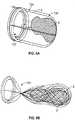
- Fig. 3Fillustrates another variation of a device where the far connector 110 includes a filter or surrounding portion 114 .
- the filter 114is sufficiently permeable to allow blood flow therethrough.
- the surrounding portion 114may be any structure that covers, encapsulates, engulfs, and/or ensnares the obstruction either fully or partially.
- the surrounding portion 114may comprise a coil, helical wire, a plurality of filaments, mesh structure, corrugated sheet, braided filaments, single wound or crossing filaments, tubes, filled tubes, castings, solid wires, membranes, films, capturing sections, (and may include ports, openings, slits, and/or holes made from photochemical etching, mechanical drilling) or any other structure that may translate or remove the obstruction 2 once the frictional component is addressed.
- the obstruction removal device 100includes leading filaments 106 connected to a near connector 108 .
- the lead filament 106may be a single wire or filament.
- the lead filamentmay comprise a single wire with a plurality of wires connecting the single wire to the ring.
- the illustrated variationshows the connector 108 as comprising a loop.
- the connectorsmay also comprise various alternate shapes (e.g., a circle, an arcuate shape, a partial circular shape, a loop, an oval, a square, a rectangle, a polygon, an overlapping loop, a pair of semi-circles, a flower shape, and a figure 8 , other shapes, etc.)
- the near connector 108is joined to a far connector 110 via a plurality of filaments 112 .
- the inventive deviceshall include at least one, but preferably two or more traversing filaments 112 .
- the obstruction removal device 100may be part of or integrated with the microcatheter 102 .
- Fig. 3Gillustrates withdrawal of the microcatheter 102 and the proximal translation of device 100 to place the surrounding portion 114 over the obstruction 2 .
- the traversing filaments 112locate towards the exterior region of the obstruction 2 .
- the connectors 108 , 110 and traversing filaments 112are designed to expand to (or near to) the perimeter of the wall of the vessel 2 and will usually locate to an exterior of the obstruction 2 .
- variations of the device and methodinclude situations where the filaments locate substantially, but not fully, towards the outer region of the obstruction. In any case, the location of the filaments 112 will sufficiently overcome the frictional forces discussed herein.
- the traversing filaments 112substantially span the length of the obstruction 2 by extending across the (proximal) 3 and (distal) 4 sides. These traversing filaments 112 provide paths for movement of the device 100 around the obstruction 2 . These paths allow for the surrounding portion 114 to engulf the entire obstruction 2 so that it may be removed from the vasculature and body.
- Fig. 3Hdepicts an obstruction removal device 100 similar to that shown in Fig. 3F .
- the near and far connectors 108, 110are both deployed distally to the obstruction 2 and then translated back over the obstruction 2 .
- this deploymentallows the traversing filaments 112 and the surrounding portion 114 to separate prior to contacting the occlusion 2 .
- the entire device 100is pulled over the occlusion 2 as described above.
- the variation of the device shown in figs 3F and 3Haddresses the frictional forces that act between the obstruction and the vessel wall.
- Conventional devices that provide a bag attached to a wireare typically unable to remove the obstruction because they cannot overcome these frictional forces that lodge the clot against the vessel wall.
- vascular filter or distal protection deviceare typically unable to remove the obstruction because they cannot overcome these frictional forces that lodge the clot against the vessel wall.
- conventional devicesare only designed to "catch" free floating clots.
- the traversing filaments described hereinare configured to be positioned surrounding the obstruction. Their low friction with respect to the clot and the vessel allows for positioning of the filaments without disrupting or further compacting the clot against the vessel wall. Once the filaments surround or are spaced about the obstruction, they reduce the friction between the clot and vessel wall by reducing points of contact. Once these filaments surrounded the clot, they permit translation of the device to permit an encapsulating section 114 to surround the obstruction for removal.
- Fig. 3Iillustrates the device 100 of Fig. 3H when translated over the obstruction 2 .
- the device 100is pulled so that the surrounding portion or blood permeable filter 114 covers the obstruction 2 (as shown in Figs. 3F and 3G .
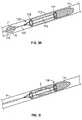
- Fig. 4Aillustrates another variation of a portion of an obstruction removal device 120 that is able to convert from a low friction mode covering to a higher friction mode covering.
- this variationallows the medical practitioner to engage an obstruction with sparse coverage or low friction mode to overcome frictional forces.
- the device configurationUpon properly engaging the obstruction, the device configuration allows conversion to a high friction mode for removal of the device and obstruction.
- this variation of the obstruction removal device 120includes two sets of traversing filaments 122, 124 and accompanying connectors 108, 110 , and 126, 128 .
- the first set 122comprises a first near connector 108 and first far connector 110 with the accompanying traversing filaments.
- the second set 124comprises the second near connector 126 and second far connector 128 with the accompanying traversing filaments 124 .
- the second set 124is coaxially located over the first set 122 .
- the materials of the componentsmay be as described above. In any case, the components are designed to expand to the perimeter of the vessel wall upon release from the catheter.
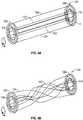
- Fig. 4Bshows the conversion of the obstruction removal device converting from a low friction mode (from Fig. 4A ) to the high friction mode.
- the first near connector 108may be rotated relative to the second near connector 126 (where the second near connector may remain still or it may be rotated in an opposite direction relative to the first near connector as shown by the arrows).
- the traversing filaments 122, 124deform in opposite directions to form a braid-type pattern increasing the friction mode over the obstruction.
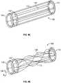
- Fig. 4Cillustrates another variation of an obstruction removal device 100 in a low friction mode state.
- the device 100includes a near connector 108 , a far connector 110 with traversing filaments between the connectors 108, 110 .
- the device 100also includes an additional connector 132 with non-rotating filaments 134 extending to the far connector 110 .
- Fig. 4Dillustrates the device 100 of Fig. 4C when the near connector 108 is rotated as shown by arrow 136 . However, the additional connector 132 and associated filaments 134 do not rotate.
- all of the filaments 112 and 134compress the obstruction over the length of the filaments. Such a feature creates additional friction on the obstruction by the device.
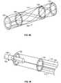
- Fig. 4Eshows another variation of an obstruction removal device 100 configured to move between low and high friction mode states.
- This variationincludes additional support rings 138 located between connectors 108, 110 and within the filaments 112 .
- the support ringskeep the device 100 at a relatively constant diameter upon assuming the increased friction mode state.
- the support ringsmay be slightly undersized compared to the connectors, allowing the filaments to slightly compress the obstruction when converted to a high friction mode, but limiting the amount of compression by limiting the resulting diameter.
- the support rings 138can be freely placed within the traversing filaments 112 . Alternatively, the rings 138 can be attached to one or more than one filament 112 to prevent undesired migration during deployment of the device.
- Fig. 4Fillustrates one example of a microcatheter 102 having a near connector 108 located externally to the catheter 102 with traversing filaments 112 extending out of the catheter and through the connector 108 .
- rotation or torquing of the catheter 102twists the filaments 112 resulting in increased friction mode of the filaments 112 over an obstruction.
- Fig. 4Fillustrates an additional connector 132 having stationary filaments 134 .
- This variation of the deviceincludes the external connector 108 directly coupled to a far connector (not shown.)
- Fig. 5Aillustrates a variation of the device 120 having only connectors 108 at one side of the device 120.
- the device 120may still include two sets 108, 122 of connectors and two sets of traversing filaments 112, 124 .
- Fig. 5Billustrates the variation of Fig. 5A after conversion to a high friction mode over the obstruction 2 .
- the connectorsmay be other structures than loops.
- variations of the inventioninclude connectors that may be drawn down to a smaller size to facilitate removal from the body after securing the obstruction. This may be accomplished by torquing the device or part thereof, by re-sheathing part or all of the device, or by any mechanical means designed into the features of the device itself. Any of these actions, or combination thereof, may also serve to compress or decrease the diameter of the obstruction itself to facilitate removal from the body.
- the devices described hereinmay be assembled or constructed in-situ.
- components of the devicemay include connectors, portions of the connectors, traversing elements, and/or surrounding sections. Any combination of these components can be placed in sequential fashion. Doing so forms a completed structure from deployment of a number of individual components. The end result is the formation of a device as shown in the figures. Accordingly, such components of the device may be separately deployed in a manner that requires "assembly" of the components by a medical practitioner during the procedure.
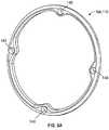
- Figs. 6A-6Gillustrate variations of the connectors 108, 110 .
- Fig. 6Ashows a loop-shaped connector 108, 110 having attachment points 140 for the filaments (not shown).
- the connectorscan be self-expanding or actuated to expand.
- the connectorsmay be fabricated from a polymer, a shape memory metal, polymer, or alloy, a super-elastic metal, polymer, or alloy, or any type of acceptable medical grade alloy, polymer, or composite structure.
- the devices described hereincan be fabricated from solid material, sheet or film, hollow or solid or filled rod or wire, braids, coils, etc. In the case of the polymer, additional strength may be added by constructing a composite layered device.
- some variations of the devicemay include a distal connector having a cap or cover to prevent the obstruction from escaping as the device is removed.
- the sizing of the connectors within the vesselcan assist in controlling relative rotation between connectors. For example, as a connector moves towards its expanded shape and engages a vessel or lumen wall, the rotational friction between the connector and lumen wall may prevent rotation. Accordingly, an adjacent connector may have a smaller expanded profile so that the connector experiences less friction when rotated.
- Fig. 6Aalso illustrates the connector as having attachment points 140 for coupling the filaments to the connectors. These attachment points may allow for movement of the filaments relative to the connector to tension or separate the connectors (as described above.)
- the filamentsmay also be coupled such that they are fixed relative to the connectors. In such a case, pulling of the lead wire will cause the entire assembly (e.g., connectors, filaments, and/o surrounding portion) to translate through the vessel.
- Figs. 6B through 6Gshow various configurations of connectors for use in the present device.
- the connectorsmay be cut from sheets, fabricated from wire, molded, stamped, laser cut, photo or chemically etched, or fabricated in any other customary manner.
- the connectors 108,110 shownmay be used in the near and/or far ends of the traversing wires. Different connector profiles may be incorporated into the device. In most cases, as shown, the connectors will form an arcuate shape so that they can expand against a vessel wall without causing trauma to the vessel.
- Figs. 6B to 6Eare shown without any accompanying traversing filaments.
- Fig. 6Bshows a connector 108, 110 that is a loop shape as shown above.
- alternative configurationsinclude a discontinuous profile, as illustrated in Fig. 6C and an overlapping profile, as illustrated in Fig. 6D .
- Such constructionsallows the connector to adjust to varying diameters of body lumens.
- a devicemay comprise loops of either construction.
- loopsare shown, other variations may work equally well.
- Variations of the inventioninclude connectors that may be drawn down to a smaller size to facilitate removal from the body once the obstruction is secured. This may be accomplished by torquing the device or part thereof, by re-sheathing part or all of the device or by any mechanical means designed into the features of the device itself.
- any of these actions, or combination thereof,may also serve to compress or decrease the diameter of the obstruction itself to facilitate removal from the body.
- the overlapping connectoras shown in Fig. 6D , may include a sliding ring type fastener that allows the overlapping connector loop to expand in the same plane.
- the devicemay be fabricated from a polymer composite that makes up the fasteners, filaments, bags, etc. where the polymeric composite is very floppy until it is exposed to either the body fluids and or some other delivered activator that causes the polymer to further polymerize or stiffen for strength.
- Various coatingscould protect the polymer from further polymerizing before the device is properly placed.
- the coatingscould provide a specific duration for placement (e.g., 5 minutes) after which the covering degrades or is activated with an agent (that doesn't affect the surrounding tissues) allowing the device to increase in stiffness so that it doesn't stretch as the thrombus is pulled out.
- shape memory polymerswould allow the device to increase in stiffness.
- Fig. 6Eshows a connector 108,110 having multiple sections 146 .
- the connector sections 146are arcuate shaped to minimize trauma to a vessel wall.
- other shapesare also intended to be within the scope of this disclosure.
- Figs. 6B through 6Galso illustrate various configurations of leading wires 106 .
- the connectorsmay have any number of leading wires. In some variations, it may be desirable to space the leading wires about the profile of the connector to aid in uniform movement of the device as it is pulled over the obstruction in the vessel.
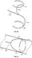
- Fig. 6F and 6Gillustrate additional variations of leading wires 106 comprising shaped wire structures that form a "c" portion 142 of the connector.
- the "c" shaped portions 142move together to allow for delivery within the catheter.
- the portions 142assume their resting shape and expand within the vessel.
- the connecting portions 142can be selected to have a size that is slightly greater than that of the vessel. Sizing the device relative to the target vessel may assist in placing the connecting portions 142 and accompanying traversing wires 112 against the wall of the vessel.
- Fig. 6Gshows an additional variation where a portion 144 of a leading wire 106 also has a "c" or semi-circular shape.
- the "c" shaped portion 144 of the leading wire 106can also be sized relative to the target vessel. Accordingly, the portion 144 of the leading wire 106 functions to drive the connecting portion 142 against the vessel wall, while the shape of the connecting portion 142 also drives the traversing wire 112 against the vessel wall.
- Fig. 6Hillustrates another variation of a leading wire 106 having an unconstrained shape that is selected to be larger than the intended vessel or simply different than a cross sectional profile of the intended vessel (i.e., not circular or tubular, but e.g., linear or other different shape).
- the leading wire 106has portions 144 that extend in opposite directions.
- This configurationis intended for illustrative purposes only. Variations include connecting portions pointing in an orthogonal direction from the main lead wire 106 , oblique, parallel (as shown), or a combination thereof.
- the unconstrained shapeis intended to have a larger profile or size than the intended vessel.
- the unconstrained shapemay have an entirely different profile than the intended vessel.
- the profile of the deviceextends radially from the vessel. So when the device and leading wire are released, the leading wire attempts to return to the unconstrained shape. In those variations where the unconstrained shape is different from the circular profile of the vessel, the leading wire assumes a shape that accommodates the vessel but is more rigid and stable since its unconstrained shape is entirely different from that of the vessel.
- Fig. 6Ishows the same device of Fig. 6H when released from a microcatheter, sheath, or tube when in the vessel.
- the leading wire 106 and accompanying portions 144attempt to revert to the unconstrained shape (as shown in Fig. 6H ).
- the vessel 6restrains the leading wire 106 and portions 144 such that the portions 144 act on the walls of the vessel. This feature allows for improved stability when deploying the leading wires and attached connectors and filaments within the vessel.
- Figs. 7A through 7Cillustrate variations of connectors 108,110 where the connector portions are axially spaced by an offset 152 .
- One benefit of placing the connector portions 142, 146 in different planesis that the device may be delivered via a smaller microcatheter because the connector portions may be collapsed to a smaller diameter.
- Fig. 7Aillustrates an offset 152 between connector portions 142 where each portion 142 is coupled to leading wires 148, 150 of varying lengths.
- Fig. 7Billustrates connector portions 146 spaced axially along a leading wire 106 to provide a gap 152 .
- Fig. 7Cillustrates a connector 108, 110 having multiple components 146 where one or more components is axially spaced to provide a gap 152 .
- Fig. 7Dshows a variation 108,110 having a flower shape where each connector portion 146 is non-planar such that the gap 152 occurs over the length of the connector portion 146 .
- Another aspect applicable to all variations of the devicesis to configure the devices (whether the traversing filament or the surrounding portion) for better adherence to the obstruction.
- One such modeincludes the use of coatings that bond to certain clots (or other materials causing the obstruction.)
- the traversing filament and/or surrounding portionmay be coated with a hydrogel or adhesive that bonds to a thrombus. Accordingly, as the surrounding portion covers the clot, or as the device twists about the clot, the combination of the additive and the mechanical structure of the device may improve the effectiveness of the device in removing the obstruction.
- the traversing membersmay have hooks, fibers, or barbs 154 that grip into the obstruction when the device converts to a high friction mode.
- the hooks, fibers, or barbs 154may also be incorporated into the surrounding portion.
- Fig. 8Billustrates a magnified view of the area 8B from Fig. 8A .
- the barbsmay be configured such that rotation in a particular direction causes the barbs to adhere to the obstruction. Such a configuration could also allow lateral movement without the barbs interfering with the vessel.
- the devicecan be coupled to an RF or other power source (such as 14 or 16 in Fig. 1 ), to allow current, ultrasound or RF energy to transmit through the device and induce clotting or cause additional coagulation of a clot or other the obstruction.
- an RF or other power sourcesuch as 14 or 16 in Fig. 1
- the methods described hereinmay also include treating the obstruction prior to attempting to remove the obstruction.
- a treatmentcan include applying a chemical or pharmaceutical agent with the goal of making the occlusion shrink or to make it more rigid for easier removal.
- agentsinclude, but are not limited to chemotherapy drugs, or solutions, a mild formalin, or aldehyde solution.
- the devices and methods described hereinmay also be useful in removing obstructions lodged within bifurcations in the anatomy.
- bifurcationsgreatly increase the frictional forces on the obstructions since the obstruction tends to be lodged in both branching sections of the bifurcation.
- the use of the presently described devices and methodsmay also include an additional "puller" device that advances beyond the portion of the obstruction partially located in the bifurcated vessel.
- Figs. 9A through 9Cillustrate additional variations of obstruction removal devices.
- the traversing filaments 112may comprise a mesh of wires connected to a single connector.
- Figs. 9A to 9Billustrate a variation in which the connector 108 comprises a wire rather than a loop.
- the filaments and connectorsshould be configured to expand to the perimeter of the vessel wall as described previously.
- Figs. 10A-10Hillustrate various additional embodiments of obstruction removal devices 130 .
- the connector 108may form a rigid wire or hard polymer to assist in placement of the device 130 .
- the surrounding portion 132may be fabricated from less rigid filaments that increase the point of contact with the obstruction.
- the surrounding portionmay also have filaments that undergo a phase change from non-rigid (or less rigid) to rigid.
- traversing filaments 112 or setsmay be used in these variations.
- the methods and or devicesmay include expansion of the vessel wall adjacent to the obstruction either with a balloon, coil, or similar mechanical expansion means, drugs, fluids, etc. Such an improvement may aid where the obstruction expands part of the vessel wall thereby increasing the amount of force required for displacement. By distending the vessel wall as described above, the forces on the obstruction maybe reduced allowing for ease of removal.
- Fig. 11Aillustrates an obstruction 2 embedded within the vessel 6 .
- Figs. 11B to 11Cillustrate variations where use of a coil ( Fig. 11B ) or a non-distensible balloon 162 ( Fig. 11C ) proximal to the obstruction 2 distends the vessel wall to loosen the obstruction 2 from the vessel. Accordingly, devices (whether described herein or other conventional devices) may then remove the obstruction 2 .
- the expansion meansmay be located on the delivery catheter of the obstruction removal device, on a wire member of the device, and/or on a separate catheter or wire used in combination with the first delivery catheter.
- variations of such configurationsare within the scope of the invention.
- devices and methods described hereinmay also use balloons proximal to the obstruction to stop or slow blood flow thereby preventing the blood from dislodging part or all of the obstruction.
Landscapes
- Health & Medical Sciences (AREA)
- Surgery (AREA)
- Life Sciences & Earth Sciences (AREA)
- Engineering & Computer Science (AREA)
- Heart & Thoracic Surgery (AREA)
- Veterinary Medicine (AREA)
- Vascular Medicine (AREA)
- Biomedical Technology (AREA)
- Nuclear Medicine, Radiotherapy & Molecular Imaging (AREA)
- Medical Informatics (AREA)
- Molecular Biology (AREA)
- Animal Behavior & Ethology (AREA)
- General Health & Medical Sciences (AREA)
- Public Health (AREA)
- Orthopedic Medicine & Surgery (AREA)
- Mechanical Engineering (AREA)
- Surgical Instruments (AREA)
- External Artificial Organs (AREA)
Description
- The devices and methods described herein relate to clearing of blockages within body lumens, such as the vasculature, by addressing the frictional resistance on the obstruction prior to attempting to translate the obstruction within the body lumen. In one variation, the devices and methods described below may treat conditions of ischemic stroke by removing blockages within arteries leading to the brain. Accordingly, variations
of such methods and devices must navigate tortuous anatomy and vasculature without causing unacceptable damage to the anatomy. Also, the devices and methods first secure and surround the obstruction (such as a clot) prior to significantly moving the clot within the anatomy. - Ischemic stroke occurs when a blockage in an artery leading to the brain causes a lack of supply of oxygen and nutrients to the brain tissue. The brain relies on its arteries to supply oxygenated blood from the heart and lungs. The blood returning from the brain carries carbon dioxide and cellular waste. Blockages that interfere with this supply eventually cause the brain tissue to stop functioning. If the disruption in supply occurs for a sufficient amount of time, the continued lack of nutrients and oxygen causes irreversible cell death (infarction). Accordingly, immediate medical treatment of an ischemic stroke is critical for the recovery of a patient.
- The infarction may not develop or may be greatly limited given a rapid clearing of the blockage to reestablish the flow of blood. However, if left untreated, ischemic stroke may lead to the permanent loss of brain tissue, and can be marked by full or partial paralysis, loss of motor control, memory loss, or death.
- Several different diseases may lead to an ischemic stroke. Typically, deposition of cholesterol (artherosclerosis), formation of blood clots, or other objects in the vessels may disrupt blood flow and lead to ischemic stroke. Furthermore, the substances that cause the blockages may break free from larger vessels outside the brain and become lodged within narrower arteries closer to the brain (embolism).
- Ischemic stroke may be divided into thrombotic strokes and embolic strokes. A thrombotic stroke occurs when the building and rupturing of atheromatous plaque within the brain blocks cerebral arteries. Clinically referred to as cerebral thrombosis or cerebral infarction, this condition represents approximately 10% of all strokes. An embolic stroke occurs when a clot or emboli forms somewhere other than in the brain, such as in the cervical carotid artery or in the heart, and travels in the bloodstream until the clot becomes lodged and can not travel any further. When such a condition occurs in the arteries supplying the brain, the condition results in almost immediate physical and neurological effects.
- While these are the most common causes of ischemic stroke, there are many other possible causes. Examples include use of drugs, trauma to the blood vessels of the neck, or blood clotting disorders.
- Apart from surgical techniques, medical practitioners could address such blockages with the use of Tissue Plasminogen Activator (t-PA). However, t-PA must be used within the first three hours of the onset of stroke symptoms and may take hours or even days to successfully restore flow. In addition, t-PA carries an increased risk of intracerebral hemorrhage. It is currently believed that the use of t-PA results in a 30% success rate as well as a 6% major complication rate. In view of these limitations, the majority of stroke patients in the U.S. do not receive t-PA treatment.
- In addition, there are a number of surgical techniques used to remove blockages. For example, an embolectomy, involves incising a blood vessel and introducing a balloon-tipped device (such as the Fogarty catheter) to the location of the occlusion. The balloon is then inflated at a point beyond the clot and used to translate the obstructing material back to the point of incision. The obstructing material is then removed by the surgeon. Concentric Medical, Inc. of Mountain View, CA supplies devices for an interventional approach to the removal of obstructions. Concentric supplies a Merci ® Retriever system as a device based approach for the removal of clots. This system engages and ensnares a clot. Once captured, a balloon catheter inflates to temporarily halt forward blood flow while the clot is withdrawn. The clot is then pulled into the catheter and out of the body.
- Typically, the existing means to remove obstructions do not address the frictional forces that act on the obstruction during removal of the obstruction. For example, some conventional devices engage the clot from the distal (or downstream) side. As the device is pulled proximally (or upstream), the device attempts to either engulf or ensnare the clot. However, due to the consistency of the clot and because the clot is typically well lodged within the vessel, the act of pulling the clot in a proximal direction cause the clot to also compress in an axial direction. This axial compression (when viewed along the axis of the vessel) causes a contemporaneous radial expansion of the clot (when viewed relative to the vessel). As a result, the increase in diameter of the clot causes an increase in the frictional forces applied against the arterial wall. Thus, by not addressing the frictional forces acting on the obstruction, the process of removing the clot may actually increase the static force that would otherwise be required to remove or translate the clot within the vessel. Unfortunately, increasing the amount of force applied upon one side of the clot also increases the probability of complications during the procedure (e.g., fragmenting the clot, failing to remove the clot, failure to fully engulf/ensnare the clot, and/or device failure) and can cause potential damage to the surrounding vessel.
- While there are other drugs and suppliers of devices for removal of blockages, there remains a need for methods and devices that improve the success rate and/or reduce the complication rate in restoring flow and thereby limit the damage from an ischemic stroke.
US 6 610 077 B1 , which is considered the prior art closest to the present invention, discloses expandable devices for repairing blood vessels. The
expandable devices are particularly suited for removing emboli or thrombi from the bloodstream of a human or animal. There is provided a loop with an embolic filter attached thereto. The loop is configured to self-expand generally perpendicularly to and optionally offset to a longitudinal axis of a delivery catheter. A tether is provided to effect the deployment from and withdrawal into the delivery catheter. The self-expandable loop and filter structure expands to occupy the entire cross-section of the lumen into which it is deployed. When the device is in its expanded configuration, the shape of the loop is defined by the lumen and the tether is positioned near a wall of the lumen.US 2005/038447 A1 discloses a medical device for removing clots from a blood vessel. A first longitudinally-oriented spine has a distal end. A pushing member is coupled to the proximal end of the first longitudinally-oriented spine and extends proximally therefrom. A clot-grabbing basket is generally disposed between and coupled to the first longitudinally-oriented spine.US 2003/144687 A1 discloses an embolic protection device comprising a collapsible filter element for delivery through a vascular system of a patient. The filter element comprises a collapsible filter body and a filter support for the filter body. The filter body has an inlet end and an outlet end, the inlet end of the filter body having one or more inlet openings sized to allow blood and embolic material enter the filter body. The outlet end of the filter body has a plurality of outlet openings sized to allow through passage of blood but to retain undesired embolic material within the filter body. The filter support is movable between a collapsed position for movement through the vascular system, and an extended outwardly projecting position to support the filter body in an expanded position. The filter support comprises a support frame defined by at least two wire segments having terminations.- According to the present invention there is provided the intravascular apparatus of
claim 1. - Additional aspects of the apparatus are set out in the dependent claims.
- It should be noted that the disclosed methods and devices may be used to treat blockages
leading to ischemic stroke as well as to treat blockages (caused by "obstructions") within other parts of the body (i.e., unless specifically noted, the devices and methods are not simply limited to the cerebral vasculature). The term obstructions may include blood clot, plaque, cholesterol, thrombus, naturally occurring foreign bodies (i.e., a part of the body that is lodged within the lumen), a non-naturally occurring foreign body (i.e., a portion of a medical device or other non-naturally occurring substance lodged within the lumen.) - In one variation of the devices described herein, the device allows for surrounding the obstruction prior to attempting to translate or move the obstruction within the vessel. It should be noted that although minimal axial movement of the obstruction may take place, the device surrounds the obstruction before such movement causes significant distortion to the geometry of the obstruction resulting in an increase in the static force required to remove the obstruction from the vessel.
- In another variation of the device, the device may include a low friction mode (such as a set of parallel wires, or wires extending axially along the lumen or vessel) that converts to an increased friction mode (such as a compressed set of wires acting on the obstruction or a twisted set of wires acting on the obstruction). The increase in friction is an increase in the friction between the obstruction and the device (as opposed to the vessel wall. In some cases, the low friction modes is a low surface area mode and the high friction mode is a high surface area mode. When configured in the low friction mode, the device is better suited to engage the obstruction without the undesirable effect of prematurely mobilizing the obstruction or compacting the obstruction (e.g., when wires are slid across the obstruction in a transverse motion). Upon engaging the obstruction, the device will conform to a high friction mode with respect to the obstruction (in some cases the device will have an increased surface area mode). This high friction mode permits the device to better grip the obstruction for ultimate removal of the obstruction.
- The operation of the devices and method described herein secure the obstruction, overcome the elastic forces of the obstruction, then remove the obstruction from the anatomy without losing or fractionating the obstruction. In one variation of the disclosure, this is accomplished by the obstruction removal device interacting with the obstruction in the following manner: (1) the traversing filaments traverse the obstruction by passing either through the obstruction or between the obstruction and the vascular wall; (2) the traversing portion is pulled proximally to engage the surrounding portion of the device around the obstruction, the surrounding portion engaging the obstruction without causing significant mobilization of the obstruction; (3) the obstruction removal device is pulled further proximally and the surrounding portion now mobilizes the obstruction.
- As shown below, variations of the devices have a configuration that provides a path for a portion of the device to surround the obstruction. The paths are made using traversing filaments that allow for low frictional translation of a surrounding portion of the device over the obstruction without causing axial translation of the obstruction. This mechanism is described in more detail below.
- Once in the proper position, a portion of the device (e.g., a surrounding portion) increases the frictional contact with the obstruction to disperse the pulling force more evenly across the obstruction. The increase points of contact allow for removal of the obstruction through tortuous anatomy while ensuring that the obstruction will not escape the encapsulation.
- The surrounding portion may be fabricated in a variety of ways. For example, the surrounding portion may comprise one or more filaments. The surrounding portion may comprise a filter/bag, a coil, helical filament, a mesh structure, corrugated sheet, braided filaments, single wound or crossing filaments, tubes, membranes, films, solid wires, filled tubes, castings. Furthermore, the surrounding portion may have one or more ports, openings, slits, and/or holes. The surrounding portion may be made by photochemical etching, mechanical drilling, weaving, braiding, laser cutting, or other means.
- It should be noted that reference to surrounding or securing the obstruction includes partially and/or fully surrounding, engulfing, encapsulating, and/or securing the obstruction. In any case, the surrounding portion engages the obstruction prior to translation of the obstruction within the lumen. As noted herein, a portion of the device may convert into a surrounding section (e.g., when traversing wires reorient to increase the friction acting on the obstruction). Accordingly, the traversing section converts into a surrounding section.
- The various devices described herein rely on a reduced profile for delivery and an expanded profile for ultimate removal of the clot. The devices, or components of the devices, may expand when released from a constraint, which allows the device, or component, to assume a predetermined shape. Alternatively, or in combination, the devices may be actuated to assume the expanded profiles. For example, the devices may be shape memory alloys that assume a profile when reaching a predetermined temperature (e.g., body temperature, or another temperature via delivery of energy to the shape memory alloy to trigger a phase change). Actuation may also include use any expandable member (such as a coiled spring, balloon, wedge, etc.) that mechanically or fluidly forces expansion of the device. These modes are well known by those skilled in the art and are intended to be within the scope of the disclosure. When combined with the inventive concepts disclosed herein, such combinations fall within the inventive scope of this disclosure.
- As noted above, the filaments of the apparatus according to the invention may be used to translate the device or may
be used to form the surrounding section. Accordingly, the filaments may be single wound or crossing filaments, tubes, membranes, films, solid wires, filled tubes, castings or any similar structure. Moreover, the cross section of such filaments may vary as required (e.g., circular, oval, rectangular, square, or any such shape.) The filaments may be constructed from metals, polymers, composites, hydrogels, membranes, shape memory metals, shape memory polymers, or shape memory alloys, superelastic metals, superelastic polymers, or superelastic alloys, or combinations thereof. The filaments may have uniform diameters or varying diameters. The characteristics of the filament may be selected to better suit their required function. For example, they can be stiff, floppy, or even have different zones of flexibility. Moreover, the filaments may be braided or woven members, or the construction may provide that the filaments cross at one or many points in an overlapping, interwoven, criss-crossing or similar manner. - It should be noted that in some variations of the invention, all or some of the filaments (used in the surrounding portion of the device) can be designed to increase their ability to adhere to the obstruction. For example, the filaments of the surrounding portion may be coupled to an energy source (e.g., RF, ultrasonic, or thermal energy) to "weld" to the obstruction. Application of energy to the filaments may allow the surrounding portion to deform into the obstruction and "embed" within the obstruction. Alternatively, the filaments may impart a positive charge to the obstruction to partially liquefy the obstruction sufficiently to allow for easier removal. Alternatively, a negative charge could be applied to further build thombus and nest the device for better pulling force. The filaments may be made stickier by use of a hydrophilic substance(s), or by chemicals that would generate a chemical bond to the surface of the obstruction.Alternatively, the filaments may reduce the temperature of the obstruction to congeal or adhere to the obstruction.
- Embodiments of apparatus in accordance with the present invention will now be described, by way of example only, with reference to the accompanying drawings. Figures that are not covered by
independent claim 1 are:Figs 5A, 5B, 9A-9C and 10A-10H , but these Figures represent technical background which is useful for understanding the intravascular apparatus of the present invention. Fig. 1 illustrates a system for removing obstructions from body lumens.Fig. 2A illustrates an example of an obstruction lodged within a body lumen.Figs. 2B to 2F illustrate advancement of a catheter beyond an obstruction and placement of traversing wires around the obstruction.Fig. 3A illustrates an obstruction removal device once converted to a high friction mode.Figs. 3B to 3E , show variations of a device having filaments that do not cross one another over the length of the obstruction when converted to a high friction mode.Fig. 3F to 3G illustrate positioning a surrounding portion and translating the surrounding portion over the obstruction.Figs. 3H to 3I illustrate an obstruction removal device deployed distally to an obstruction and then translated proximally over the obstruction.Figs. 4A to 4E illustrate various additional configurations of devices able to assume a high friction mode covering over an obstruction.Fig. 4F illustrates a variation of a device using an end of a catheter for converting the device to a high friction mode.Figs. 5A to 5B illustrate a variation of a portion of an obstruction removal device configured to convert from a low friction mode to a high friction mode.Figs. 6A to 6G illustrate various configurations of connectors for use with obstruction removal devices.Figs. 6H to 6I illustrate a variation of a leading wire and connector having an unconstrained shape that is selected to be larger or simply different than the intended vessel to provide increased stability upon deployment.Fig. 7A to 7D illustrates variations in which the connector is offset.Figs. 8A to 8B illustrate hooks, fibers, and/or barbs for increasing the ability of the device to remove obstructions.Figs. 9A to 9C illustrate additional variations of obstruction removal devices.Figs. 10A to 10H also illustrate additional variations of obstruction removal devices, focusing mainly on variations of the surrounding portion.Figs. 11A to 11C illustrate a variation where use of mechanical expansion distends the vessel wall and loosens the obstruction from the vessel.- It is understood that the examples below discuss uses in the cerebral vasculature (namely the arteries). However, unless specifically noted, variations of the device and method are not limited to use in the cerebral vasculature. Instead, the invention may have applicability in various parts of the body. Moreover, the invention may be used in various procedures where the benefits of the method and/or device are desired.
Fig. 1 illustrates asystem 10 for removing obstructions from body lumens as described herein. In the illustrated example, this variation of thesystem 10 is suited for removal of an obstruction in the cerebral vasculature. Typically, thesystem 10 includes acatheter 12 microcatheter, sheath, guide-catheter, or simple tube/sheath configuration for delivery of the obstruction removal device to the target anatomy. The catheter should be sufficient to deliver the device as discussed below. Thecatheter 12 may optionally include aninflatable balloon 18 for temporarily blocking blood flow or for expanding the vessel to release the obstruction- It is noted that any number of catheters or microcatheters maybe used to locate the catheter/
microcatheter 12 carrying the obstruction removal device (not illustrated) at the desired target site. Such techniques are well understood standard interventional catheterization techniques. Furthermore, thecatheter 12 may be coupled to auxiliary orsupport components 14,16 (e.g., energy controllers, power supplies, actuators for movement of the device(s), vacuum sources, inflation sources, sources for therapeutic substances, pressure monitoring, flow monitoring, various bio-chemical sensors, bio-chemical substance, etc.) Again, such components are within the scope of thesystem 10 described herein. - In addition, devices of the present invention may be packaged in kits including the components discussed above along with guiding catheters, various devices that assist in the stabilization or removal of the obstruction (e.g., proximal-assist devices that holds the proximal end of the obstruction in place preventing it from straying during removal or assisting in the removal of the obstruction), balloon-tipped guide catheters, dilators, etc.
Figs. 2A to 2F show one example of the deployment of the basic structure of connectors and traversing filaments about an obstruction in a vessel. The figures are intended to demonstrate the initial placement of the connectors and filaments immediately prior to removal of the obstruction either using a filter or by torquing, rotating and/or twisting the near connector relative to the far connector. This action converts the device from a low friction device to a high friction device (where the low/high friction is the friction between the device and the obstruction). This action may also be referred to as a low surface area mode converting to a high surface area mode (in cases where the device extends beyond the obstruction and relative motion between ends of the device causes the device to shrink in axial length as it is twisted.) In addition, the number of connectors used, the shape of the connectors, as well as the number of filaments is intended to be for illustrative purposes only. It is contemplated that any variation of connector and/or filament may be deployed in a similar manner.Fig. 2A illustrates an example of anobstruction 2 lodged within a body lumen orvessel 6. In the case where the vessel is a cerebral artery, the obstruction may result in an ischemic stroke. Using standard interventional catheterization techniques, amicrocatheter 102 and guidewire104 traverse the obstruction. Themicrocatheter 102 may be advanced through theobstruction 2. Alternatively, themicrocatheter 102 may "push" aside the obstruction and is advanced around the obstruction. In any case, themicrocatheter 102 travels from the near end3 (or proximal side) of theobstruction 2 to the far end4 (or distal side) of theobstruction 2. It is noted that thecatheter 102 may be centered or off-center with respect to theobstruction 2. Furthermore, the device may or may not be used with a guidewire to navigate to the site and traverse the obstruction.Fig. 2B shows another variation where amicrocatheter 102 traverses theobstruction 2 between the wall of thevessel 6 and theobstruction 2. As shown, the open end of themicrocatheter 102 is distal to theobstruction 2 and is now positioned to deploy devices for removal of theobstruction 2. This variation shows the device after removal of any guidewire. However, some variations of the device may be placed without an accompanying guidewire. Moreover, the structures discussed herein may be directly incorporated into a guidewire assembly where deployment may require a sheath or other covering to release the components from constraint.Fig. 2C illustrates deployment of afar connector 110 from within themicrocatheter 102 distal to theobstruction 2. Thefar connector 110 can be self-expanding such that it assumes, or moves towards, the expanded profile (as shown) upon deployment from the constraint of themicrocatheter 102.- The
connectors filaments 112 are designed to expand to the wall of the vessel when released from the catheter. This action allows thedevice 100 to surround theobstruction 2 prior to attempting to dislodge it. The components of the obstruction removal device100 (e.g., the leadingwires 106, theconnectors 108 110, the traversingfilaments 112, and/or the surrounding portion114) may be fabricated from any biocompatible material that permits the function as described herein. In some variations, the material may comprise a shape memory or super-elastic alloy such as nitinol. Fig. 2D shows withdrawal of themicrocatheter 102 to theproximal side 3 of theobstruction 2. The spacing between thefar connector 110 and theobstruction 2 may vary. In some cases, thefar connector 110 will move closer towards theobstruction 2 during spacing of the traversingfilaments 112 as discussed below. Thefar connector 110 remains in place either using the inherent friction of the connector against the vessels and/orobstruction 2. Alternatively, or in combination, a wire-type member (not shown) may provide an opposing force against theconnector 110 as thecatheter 102 moves proximal to theobstruction 2.- As discussed herein, the obstruction removal devices include a plurality of filaments affixed between connectors. Since the
far connector 110 is deployed at thedistal side 4 of theobstruction 2, withdrawal of themicrocatheter 102 results in the plurality offilaments 112 spanning across theobstruction 2 as shown. Fig. 2E illustrates deployment of anear connector 108. Although the illustrated variation depicts thenear connector 108 as being deployed from within themicrocatheter 102, alternative variations of the device include anear connector 108 that is located about the exterior of themicrocatheter 102 or that is located about another delivery device (not shown) that is external to themicrocatheter 102. In this case, thenear connector 108 is similar in profile and design to thefar connector 110. Accordingly, thenear connector 108 self expands within thevessel 6 upon deployment from themicrocatheter 102. In some variations of the device, the near and far connectors108,110 may have different shapes or profiles. In any case, the profile of the connectors should be sufficient to expand the traversing wires sufficiently within the vessel to prepare for ensnaring or encapsulation of theobstruction 2.Fig. 2E also illustrates a connecting or leading wire/member 106 that couples themicrocatheter 102 to thenear connector 108. The term leading wire, leading member, lead wire, etc. is intended to encompass a wire, tube, or any other structure that organizes and sometimes houses the smaller traversing filaments and/or near connectors described herein. Naturally, variations of the device include aleading wire 106 that is affixed to the far connector or the traversing wires. Moreover, the illustration depicts a singleleading wire 106. However, as noted below, the device can include a number oftraversing wire 106 affixed to the near and/orfar connectors Fig. 2F illustrates spacing the traversing filaments/wires 112 from simply spanning the obstruction2 (as depicted inFig. 2E ). This action causes thefilaments 112 to span theobstruction 2 while reorienting towards an exterior of theobstruction 2. As noted herein, the traversingfilaments 112 may remain partially or fully within theobstruction 2. However, given that the filaments are spaced about the connectors, the filaments shall separate radially over the obstruction allowing for the subsequent ensnaring and removal.- Spacing the filaments may occur via a number of modes such as tensioning, expanding, spreading separating and/or withdrawing the filaments. In certain variations of the device, the filaments are moveable relative to a near connector and/or a far connector. Such a feature allows application of tension to the filaments while keeping the connector in place. This causes the filament to enter a state of tension for spacing about the wall of the vessel. Alternatively, the filaments may be fixed relative to the connectors. Upon deployment the filaments either self expand or are actuated to space about the vessel wall for eventual translation of the device over the obstruction. Regardless of the mode used, the filaments are intended to be positioned at or near a surface of the obstruction so that they can reduce the effects of any friction between the obstruction and the lumen or vessel wall.
Figs. 3A to 3I provide illustrations of device variations that ensnare theobstruction 2 after the device is in the configuration demonstrated byFig. 2F above.Figs. 3A ,3C , and3E represent variations of thedevice 100 after transforming from a low friction mode to a higher friction mode for removal of the obstruction.Figs. 3F and 3G illustrate a variation where a surrounding portion or filter covers the obstruction for its ultimate removal from the body.Fig. 3A illustrates rotation of thenear connector 108 relative to thefar connector 110 to ensnare theobstruction 2 within the traversingwires 112. Alternatively, each connector may rotate with the rate of rotation for one connector being slower than another. In yet another variation, each connector may be rotated in opposite directions.- Although the variation shows only four traversing
wires 112 any number of wires may be used so long as the rotation converts the traversingwires 112 into a relatively increased friction mode as compared to the low friction mode (when the traversing wires are in a parallel configuration). The low friction mode is represented byFig. 2F. Fig. 3A illustrates theobstruction removal device 100 after rotation of the sets of traversing filaments and connectors. The result is that theobstruction 2 becomes ensnared (and/or encapsulated) and may be removed from the body. It should be noted that the same effect may be achieved by only rotating one connector or set of wires while keeping the other connector or set of wires stationary. - The rotation of the
connector 108 can be performed in any number of ways as known to those skilled in the art. However, as shown inFig. 3A , thelead wire 106 may comprise additional secondary wires attached to theconnector 108. So rotation of theconnector 108 may occur via rotation of the lead wire and/or microcatheter. In any case, once the device assumes the increased friction mode condition, theobstruction 2 can be moved laterally within the vessel for removal. Figs. 3A to 3E illustrate various configurations where relative rotation of the connectors108,110 convert the device into a high friction mode. InFig. 3A , the traversingfilaments 112 twist and cross one another over the length of theobstruction 2. However, as shown inFigs. 3B to 3E , variations of thedevice 100 can havefilaments 112 that do not cross one another over the length of theobstruction 2. Although these variations are depicted to have single connectors on each end and four filaments, the design of the devices may vary as required by the particular application. In addition, the variations shown inFig. 3B to 3E are shown without any catheter or leading wire for convenience to better illustrate the conversion of the device from a low friction mode to a high friction mode. Naturally, rotation of the catheter and/or lead wire will cause relative rotation between connectors.- In
Fig. 3B , thedevice 100 is in a similar position as that shown inFig. 2E . However,Fig. 3B shows a variation of adevice 100 that is is selected to have a length greater than the targetedobstruction 2. Upon rotation, the traversingfilaments 112 remain uncrossed over the length of theobstruction 2. In some cases, thefilaments 112 may experience some twisting and will not remain parallel. However, thefilaments 112 twist at twist points116 that are proximal to and distal to theobstruction 2. The relative motion of theconnectors twist point 116 causes thefilaments 112 to exert a compressive force on theobstruction 2 without crossing one another over the length of the construction. Accordingly, while the surface area in contact between thefilaments 112 andobstruction 2 remains relatively the same, the compressive action of thefilaments 112 onto the obstruction converts thedevice 100 to a high friction mode on the obstruction. Fig. 3D illustrates another variation of a device in a similar position as that shown inFig. 2E . However,Fig. 3D shows a variation of adevice 100 that extends proximally from the near end of theobstruction 2. The relative motion between connectors108,110 causes atwist point 116 that is proximal to theobstruction 2. As with the previous variation, thetwist point 116 forces thefilaments 112 against theobstruction 2 without crossing one another over the length of theobstruction 2. As a result, thedevice 100 is now in high friction mode. In some cases, thefilaments 112 may experience some twisting and will not remain parallel.- The variation of
Figs. 3D and3E also show thedevice 100 as including a cap or cover118 about thedistal connector 110. The cap or cover118 may be a bag, mesh, a continuation of thefilaments 112, and/or a surroundingportion 114 as discussed herein. The cap or cover118 reduces the likelihood that the obstruction is driven through thefar connector 110 during conversion of thedevice 100 from a low friction mode to a high friction mode. Fig. 3F illustrates another variation of a device where thefar connector 110 includes a filter or surroundingportion 114. In variations of the device, thefilter 114 is sufficiently permeable to allow blood flow therethrough. As noted above, the surroundingportion 114 may be any structure that covers, encapsulates, engulfs, and/or ensnares the obstruction either fully or partially. Accordingly, although the surroundingportion 114 is illustrated as a filter/bag, the surroundingportion 114 may comprise a coil, helical wire, a plurality of filaments, mesh structure, corrugated sheet, braided filaments, single wound or crossing filaments, tubes, filled tubes, castings, solid wires, membranes, films, capturing sections, (and may include ports, openings, slits, and/or holes made from photochemical etching, mechanical drilling) or any other structure that may translate or remove theobstruction 2 once the frictional component is addressed.- In this variation, the
obstruction removal device 100 includes leadingfilaments 106 connected to anear connector 108. In this example, thelead filament 106 may be a single wire or filament. Alternatively, the lead filament may comprise a single wire with a plurality of wires connecting the single wire to the ring. - As with the above examples, the illustrated variation shows the
connector 108 as comprising a loop. However, as described herein, the connectors may also comprise various alternate shapes (e.g., a circle, an arcuate shape, a partial circular shape, a loop, an oval, a square, a rectangle, a polygon, an overlapping loop, a pair of semi-circles, a flower shape, and afigure 8 , other shapes, etc.) Thenear connector 108 is joined to afar connector 110 via a plurality offilaments 112. It is noted that the inventive device shall include at least one, but preferably two ormore traversing filaments 112. It is further noted that theobstruction removal device 100 may be part of or integrated with themicrocatheter 102. Fig. 3G illustrates withdrawal of themicrocatheter 102 and the proximal translation ofdevice 100 to place the surroundingportion 114 over theobstruction 2. As theobstruction removal device 100 translates proximally, the traversingfilaments 112 locate towards the exterior region of theobstruction 2. As discussed above, theconnectors filaments 112 are designed to expand to (or near to) the perimeter of the wall of thevessel 2 and will usually locate to an exterior of theobstruction 2. However, variations of the device and method include situations where the filaments locate substantially, but not fully, towards the outer region of the obstruction. In any case, the location of thefilaments 112 will sufficiently overcome the frictional forces discussed herein. In the illustrated variation, the traversingfilaments 112 substantially span the length of theobstruction 2 by extending across the (proximal)3 and (distal)4 sides. These traversingfilaments 112 provide paths for movement of thedevice 100 around theobstruction 2. These paths allow for the surroundingportion 114 to engulf theentire obstruction 2 so that it may be removed from the vasculature and body.Fig. 3H depicts anobstruction removal device 100 similar to that shown inFig. 3F . However, in this variation, the near andfar connectors obstruction 2 and then translated back over theobstruction 2. As shown, this deployment allows the traversingfilaments 112 and the surroundingportion 114 to separate prior to contacting theocclusion 2. Next, theentire device 100 is pulled over theocclusion 2 as described above. The variation of the device shown infigs 3F and3H addresses the frictional forces that act between the obstruction and the vessel wall. Conventional devices that provide a bag attached to a wire (such as a vascular filter or distal protection device), are typically unable to remove the obstruction because they cannot overcome these frictional forces that lodge the clot against the vessel wall. Typically, such conventional devices are only designed to "catch" free floating clots. The traversing filaments described herein are configured to be positioned surrounding the obstruction. Their low friction with respect to the clot and the vessel allows for positioning of the filaments without disrupting or further compacting the clot against the vessel wall. Once the filaments surround or are spaced about the obstruction, they reduce the friction between the clot and vessel wall by reducing points of contact. Once these filaments surrounded the clot, they permit translation of the device to permit anencapsulating section 114 to surround the obstruction for removal.Fig. 3I illustrates thedevice 100 ofFig. 3H when translated over theobstruction 2. Eventually, thedevice 100 is pulled so that the surrounding portion or bloodpermeable filter 114 covers the obstruction2 (as shown inFigs. 3F and 3G .Fig. 4A illustrates another variation of a portion of anobstruction removal device 120 that is able to convert from a low friction mode covering to a higher friction mode covering. As noted above, this variation allows the medical practitioner to engage an obstruction with sparse coverage or low friction mode to overcome frictional forces. Upon properly engaging the obstruction, the device configuration allows conversion to a high friction mode for removal of the device and obstruction.- As shown, this variation of the
obstruction removal device 120 includes two sets of traversingfilaments connectors first set 122 comprises a firstnear connector 108 and firstfar connector 110 with the accompanying traversing filaments. Thesecond set 124 comprises the secondnear connector 126 and secondfar connector 128 with the accompanying traversingfilaments 124. Thesecond set 124 is coaxially located over thefirst set 122. The materials of the components may be as described above. In any case, the components are designed to expand to the perimeter of the vessel wall upon release from the catheter. Fig. 4B shows the conversion of the obstruction removal device converting from a low friction mode (fromFig. 4A ) to the high friction mode. For example, the firstnear connector 108 may be rotated relative to the second near connector126 (where the second near connector may remain still or it may be rotated in an opposite direction relative to the first near connector as shown by the arrows). As a result, the traversingfilaments Fig. 4C illustrates another variation of anobstruction removal device 100 in a low friction mode state. In this variation, thedevice 100 includes anear connector 108, afar connector 110 with traversing filaments between theconnectors device 100 also includes anadditional connector 132 withnon-rotating filaments 134 extending to thefar connector 110.Fig. 4D illustrates thedevice 100 ofFig. 4C when thenear connector 108 is rotated as shown byarrow 136. However, theadditional connector 132 and associatedfilaments 134 do not rotate. Upon rotation of thenear connector 108 and twisting of thefilaments 112, all of thefilaments Fig. 4E shows another variation of anobstruction removal device 100 configured to move between low and high friction mode states. This variation includes additional support rings138 located betweenconnectors filaments 112. The support rings keep thedevice 100 at a relatively constant diameter upon assuming the increased friction mode state. The support rings may be slightly undersized compared to the connectors, allowing the filaments to slightly compress the obstruction when converted to a high friction mode, but limiting the amount of compression by limiting the resulting diameter. The support rings138 can be freely placed within the traversingfilaments 112. Alternatively, therings 138 can be attached to one or more than onefilament 112 to prevent undesired migration during deployment of the device.Fig. 4F illustrates one example of amicrocatheter 102 having anear connector 108 located externally to thecatheter 102 with traversingfilaments 112 extending out of the catheter and through theconnector 108. In this variation, rotation or torquing of thecatheter 102 twists thefilaments 112 resulting in increased friction mode of thefilaments 112 over an obstruction.Fig. 4F illustrates anadditional connector 132 havingstationary filaments 134. This variation of the device includes theexternal connector 108 directly coupled to a far connector (not shown.)Fig. 5A illustrates a variation of thedevice 120 having onlyconnectors 108 at one side of thedevice 120. In this variation, thedevice 120 may still include twosets filaments Fig. 5B illustrates the variation ofFig. 5A after conversion to a high friction mode over theobstruction 2. As discussed herein, the connectors may be other structures than loops. Moreover, variations of the invention include connectors that may be drawn down to a smaller size to facilitate removal from the body after securing the obstruction. This may be accomplished by torquing the device or part thereof, by re-sheathing part or all of the device, or by any mechanical means designed into the features of the device itself. Any of these actions, or combination thereof, may also serve to compress or decrease the diameter of the obstruction itself to facilitate removal from the body.- In another variation, the devices described herein may be assembled or constructed in-situ. For example, components of the device may include connectors, portions of the connectors, traversing elements, and/or surrounding sections. Any combination of these components can be placed in sequential fashion. Doing so forms a completed structure from deployment of a number of individual components. The end result is the formation of a device as shown in the figures. Accordingly, such components of the device may be separately deployed in a manner that requires "assembly" of the components by a medical practitioner during the procedure.
Figs. 6A-6G illustrate variations of theconnectors Fig. 6A shows a loop-shapedconnector Fig. 6A also illustrates the connector as having attachment points140 for coupling the filaments to the connectors. These attachment points may allow for movement of the filaments relative to the connector to tension or separate the connectors (as described above.) The filaments may also be coupled such that they are fixed relative to the connectors. In such a case, pulling of the lead wire will cause the entire assembly (e.g., connectors, filaments, and/o surrounding portion) to translate through the vessel.Figs. 6B through 6G show various configurations of connectors for use in the present device. The connectors may be cut from sheets, fabricated from wire, molded, stamped, laser cut, photo or chemically etched, or fabricated in any other customary manner. Moreover, the connectors108,110 shown may be used in the near and/or far ends of the traversing wires. Different connector profiles may be incorporated into the device. In most cases, as shown, the connectors will form an arcuate shape so that they can expand against a vessel wall without causing trauma to the vessel. To illustrate the connector configurations,Figs. 6B to 6E are shown without any accompanying traversing filaments.Fig. 6B shows aconnector Fig. 6C and an overlapping profile, as illustrated inFig. 6D . Such constructions allows the connector to adjust to varying diameters of body lumens. It is noted that a device may comprise loops of either construction. It should be also noted that although loops are shown, other variations may work equally well. Variations of the invention include connectors that may be drawn down to a smaller size to facilitate removal from the body once the obstruction is secured. This may be accomplished by torquing the device or part thereof, by re-sheathing part or all of the device or by any mechanical means designed into the features of the device itself. Any of these actions, or combination thereof, may also serve to compress or decrease the diameter of the obstruction itself to facilitate removal from the body. In addition, the overlapping connector, as shown inFig. 6D , may include a sliding ring type fastener that allows the overlapping connector loop to expand in the same plane.- In another example, the device may be fabricated from a polymer composite that makes up the fasteners, filaments, bags, etc. where the polymeric composite is very floppy until it is exposed to either the body fluids and or some other delivered activator that causes the polymer to further polymerize or stiffen for strength. Various coatings could protect the polymer from further polymerizing before the device is properly placed. The coatings could provide a specific duration for placement (e.g., 5 minutes) after which the covering degrades or is activated with an agent (that doesn't affect the surrounding tissues) allowing the device to increase in stiffness so that it doesn't stretch as the thrombus is pulled out. For example, shape memory polymers would allow the device to increase in stiffness.
Fig. 6E shows a connector108,110 havingmultiple sections 146. As noted above, theconnector sections 146 are arcuate shaped to minimize trauma to a vessel wall. However, other shapes are also intended to be within the scope of this disclosure.Figs. 6B through 6G also illustrate various configurations of leadingwires 106. The connectors may have any number of leading wires. In some variations, it may be desirable to space the leading wires about the profile of the connector to aid in uniform movement of the device as it is pulled over the obstruction in the vessel.Fig. 6F and 6G illustrate additional variations of leadingwires 106 comprising shaped wire structures that form a "c"portion 142 of the connector. In one variation, when constrained the "c" shapedportions 142 move together to allow for delivery within the catheter. Upon release from the catheter, theportions 142 assume their resting shape and expand within the vessel. The connectingportions 142 can be selected to have a size that is slightly greater than that of the vessel. Sizing the device relative to the target vessel may assist in placing the connectingportions 142 and accompanying traversingwires 112 against the wall of the vessel.Fig. 6G shows an additional variation where aportion 144 of aleading wire 106 also has a "c" or semi-circular shape. In this configuration, the "c" shapedportion 144 of theleading wire 106 can also be sized relative to the target vessel. Accordingly, theportion 144 of theleading wire 106 functions to drive the connectingportion 142 against the vessel wall, while the shape of the connectingportion 142 also drives thetraversing wire 112 against the vessel wall.Fig. 6H illustrates another variation of aleading wire 106 having an unconstrained shape that is selected to be larger than the intended vessel or simply different than a cross sectional profile of the intended vessel (i.e., not circular or tubular, but e.g., linear or other different shape). In this variation, the leadingwire 106 hasportions 144 that extend in opposite directions. This configuration is intended for illustrative purposes only. Variations include connecting portions pointing in an orthogonal direction from themain lead wire 106, oblique, parallel (as shown), or a combination thereof. In any case, the unconstrained shape is intended to have a larger profile or size than the intended vessel. Moreover, the unconstrained shape may have an entirely different profile than the intended vessel. As shown in the figures, the profile of the device extends radially from the vessel. So when the device and leading wire are released, the leading wire attempts to return to the unconstrained shape. In those variations where the unconstrained shape is different from the circular profile of the vessel, the leading wire assumes a shape that accommodates the vessel but is more rigid and stable since its unconstrained shape is entirely different from that of the vessel.Fig. 6I shows the same device ofFig. 6H when released from a microcatheter, sheath, or tube when in the vessel. Once released, the leadingwire 106 and accompanyingportions 144 attempt to revert to the unconstrained shape (as shown inFig. 6H ). However, thevessel 6 restrains theleading wire 106 andportions 144 such that theportions 144 act on the walls of the vessel. This feature allows for improved stability when deploying the leading wires and attached connectors and filaments within the vessel.Figs. 7A through 7C illustrate variations of connectors108,110 where the connector portions are axially spaced by an offset152. One benefit of placing theconnector portions Fig. 7A illustrates an offset152 betweenconnector portions 142 where eachportion 142 is coupled to leadingwires Fig. 7B illustratesconnector portions 146 spaced axially along aleading wire 106 to provide agap 152.Fig. 7C illustrates aconnector multiple components 146 where one or more components is axially spaced to provide agap 152.Fig. 7D shows a variation108,110 having a flower shape where eachconnector portion 146 is non-planar such that thegap 152 occurs over the length of theconnector portion 146.- Another aspect applicable to all variations of the devices is to configure the devices (whether the traversing filament or the surrounding portion) for better adherence to the obstruction. One such mode includes the use of coatings that bond to certain clots (or other materials causing the obstruction.) For example, the traversing filament and/or surrounding portion may be coated with a hydrogel or adhesive that bonds to a thrombus. Accordingly, as the surrounding portion covers the clot, or as the device twists about the clot, the combination of the additive and the mechanical structure of the device may improve the effectiveness of the device in removing the obstruction.
- Such improvements may also be mechanical or structural. For example, as shown in
Fig. 8A , the traversing members may have hooks, fibers, orbarbs 154 that grip into the obstruction when the device converts to a high friction mode. The hooks, fibers, orbarbs 154 may also be incorporated into the surrounding portion. However, it will be important that such features do not hinder the ability of the practitioner to remove the device from the body. For example,Fig. 8B illustrates a magnified view of thearea 8B fromFig. 8A . As illustrated, the barbs may be configured such that rotation in a particular direction causes the barbs to adhere to the obstruction. Such a configuration could also allow lateral movement without the barbs interfering with the vessel. - In addition to additives, the device can be coupled to an RF or other power source (such as14 or16 in
Fig. 1 ), to allow current, ultrasound or RF energy to transmit through the device and induce clotting or cause additional coagulation of a clot or other the obstruction. - The methods described herein may also include treating the obstruction prior to attempting to remove the obstruction. Such a treatment can include applying a chemical or pharmaceutical agent with the goal of making the occlusion shrink or to make it more rigid for easier removal. Such agents include, but are not limited to chemotherapy drugs, or solutions, a mild formalin, or aldehyde solution.
- Although not illustrated, the devices and methods described herein may also be useful in removing obstructions lodged within bifurcations in the anatomy. Generally, bifurcations greatly increase the frictional forces on the obstructions since the obstruction tends to be lodged in both branching sections of the bifurcation. In such cases, the use of the presently described devices and methods may also include an additional "puller" device that advances beyond the portion of the obstruction partially located in the bifurcated vessel.
- As for other details of the present invention, materials and manufacturing techniques may be employed as within the level of those with skill in the relevant art. The same may hold true with respect to method-based aspects of the invention in terms of additional acts that are commonly or logically employed. In addition, though the invention has been described in reference to several examples, optionally incorporating various features, the invention is not to be limited to that which is described or indicated as contemplated with respect to each variation of the invention.
Figs. 9A through 9C illustrate additional variations of obstruction removal devices. In these variations, the traversingfilaments 112 may comprise a mesh of wires connected to a single
connector.Figs. 9A to 9B illustrate a variation in which theconnector 108 comprises a wire rather than a loop. However, the filaments and connectors should be configured to expand to the perimeter of the vessel wall as described previously.Figs. 10A-10H illustrate various additional embodiments ofobstruction removal devices 130. In these variations, theconnector 108 may form a rigid wire or hard polymer to assist in placement of thedevice 130. The surroundingportion 132 may be fabricated from less rigid filaments that increase the point of contact with the obstruction. The surrounding portion may also have filaments that undergo a phase change from non-rigid (or less rigid) to rigid.- It should be noted that any number of traversing
filaments 112 or sets may be used in these variations. - In additional aspect of the invention, as shown in
Fig. 11A to 11C , the methods and or devices may include expansion of the vessel wall adjacent to the obstruction either with a balloon, coil, or similar mechanical expansion means, drugs, fluids, etc. Such an improvement may aid where the obstruction expands part of the vessel wall thereby increasing the amount of force required for displacement. By distending the vessel wall as described above, the forces on the obstruction maybe reduced allowing for ease of removal.Fig. 11A illustrates anobstruction 2 embedded within thevessel 6.Figs. 11B to 11C illustrate variations where use of a coil (Fig. 11B ) or a non-distensible balloon162 (Fig. 11C ) proximal to theobstruction 2 distends the vessel wall to loosen theobstruction 2 from the vessel. Accordingly, devices (whether described herein or other conventional devices) may then remove theobstruction 2. - In those variations with a mechanical expansion means, the expansion means may be located on the delivery catheter of the obstruction removal device, on a wire member of the device, and/or on a separate catheter or wire used in combination with the first delivery catheter. However, variations of such configurations are within the scope of the invention.
- In addition, devices and methods described herein may also use balloons proximal to the obstruction to stop or slow blood flow thereby preventing the blood from dislodging part or all of the obstruction.
- Various changes may be made to the invention described and equivalents (whether recited herein or not included for the sake of some brevity) may be substituted without departing from the scope of the claims. Also, any optional feature of the inventive variations may be set forth and claimed independently, or in combination with any one or more of the features described herein. Accordingly, the invention contemplates combinations of various aspects of the embodiments or combinations of the embodiments themselves, where possible. Reference to a singular item, includes the possibility that there are plural of the same items present. More specifically, as used herein and in the appended claims, the singular forms "a," "and," "said," and "the" include plural references unless the context clearly dictates otherwise.
Claims (15)
- An intravascular apparatus for removing an obstruction from a vessel of a patient, the device comprising:a microcatheter (102) having a size and flexibility to navigate within a neurovascular region of the patient;a near connector (108) having a first expanded profile when unconstrained, such that on deployment in the vessel the near connector expands towards the first expanded profile;a far connector (110) being collapsible to fit within the microcatheter and having a second expanded profile when unconstrained, such that on deployment in the vessel the far connector expands towards the second expanded profile;at least one lead filament (106) coupling the near connector to the microcatheter; anda plurality of traversing filaments (112) extending between the near and far connectors, and spaced apart on each connector such that tensioning the traversing filaments causes the filaments (112) to move towards a wall of the vessel ,characterized in that the near
connector can be rotated relative to the far connector to ensnare the obstruction. - The intravascular apparatus of claim 1, wherein at least one of the traversing filaments is moveable relative to the near and far connectors so that tension may be applied to the respective filament to spread the filaments.
- The intravascular apparatus of claim 1, where the near and far connectors are rotatable relative to each other to cause at least a section of the plurality of filaments to cross one another.
- The intravascular apparatus of claim 3, wherein the far connector is stationary and the near connector is rotatable.
- The intravascular apparatus of claim 1, where at least one of the traversing filaments is moveable relative to the near connector so that tension may be applied to the respective filament to spread the filaments.
- The intravascular apparatus of claim 1, where the filaments are fixed relative to the near connector such that axial movement of the lead wire causes axial movement of the near connector and filaments.
- The intravascular apparatus of claim 1, wherein:the expanded profile of the near connector comprises a shape selected from a
circle, an arcuate shape, a partial circular shape, a loop, an oval, a square, a rectangle, a polygon, an overlapping loop, a pair of semi-circles, a flower shape, and a figure 8; orthe expanded profile of the far connector comprises a shape selected from a circle,
an arcuate shape, a partial circular shape, a loop, an oval, a square, a rectangle, a polygon, an overlapping loop, a pair of semi-circles, a flower shape, and a figure 8. - The intravascular apparatus of claim 1, further comprising:a plurality of hook shaped members located on at least one filament; orat least one support ring within the filament.
- The intravascular apparatus of claim 1, wherein:the or each near connector is collapsible to fit within the microcatheter; orthe or a near connector is affixed to an exterior of the microcatheter; orthe or each near connector comprises a plurality of near connector portions, at least one of which near connector portions may be axially spaced from another near connector portion; orthe near connector, the lead filament, and the plurality of traversing filaments, are collapsible to fit within the microcatheter and are self-expanding upon deployment from the microcatheter.
- The intravascular apparatus of claim 1, where the or each far connectors comprises a plurality of far connector portions, at least one of which far connector portions may be axially spaced from another far connector portion.
- The intravascular apparatus of claim 1, further comprising a third connector located adjacent to the near connector, and a plurality of non-rotating filaments extending between the far connector and the third connector, where the first connector is rotatable relative to the far and third connectors to cause the plurality of traversing filaments to form a mesh pattern or a helical pattern.
- The intravascular apparatus of claim 1, where the near connector, the lead filament, and the plurality of traversing filaments, are collapsible to fit within the microcatheter and are actuated to expand upon deployment from the microcatheter.
- The intravascular apparatus of claim 1, wherein the apparatus further comprises a balloon located on the microcatheter, where on expansion the balloon expands the vessel allowing for removal of the obstruction.
- The intravascular apparatus of claim 1, wherein the apparatus further comprises an expandable coil located on the microcatheter and having an expanded profile, where deployment of the coil causes expansion of the vessel allowing for removal of the obstruction.
- The intravascular apparatus of claim 1, where at least one of the traversing filaments is moveable relative to the far connector so that tension may be applied to the respective filament to spread the filaments.
Applications Claiming Priority (2)
| Application Number | Priority Date | Filing Date | Title |
|---|---|---|---|
| US76549606P | 2006-02-03 | 2006-02-03 | |
| PCT/US2007/061634WO2007092820A2 (en) | 2006-02-03 | 2007-02-05 | Methods and devices for restoring blood flow within blocked vasculature |
Publications (3)
| Publication Number | Publication Date |
|---|---|
| EP1986568A2 EP1986568A2 (en) | 2008-11-05 |
| EP1986568A4 EP1986568A4 (en) | 2012-12-05 |
| EP1986568B1true EP1986568B1 (en) | 2017-04-05 |
Family
ID=38335001
Family Applications (1)
| Application Number | Title | Priority Date | Filing Date |
|---|---|---|---|
| EP07763224.8ANot-in-forceEP1986568B1 (en) | 2006-02-03 | 2007-02-05 | Methods and devices for restoring blood flow within blocked vasculature |
Country Status (3)
| Country | Link |
|---|---|
| US (9) | US20070225749A1 (en) |
| EP (1) | EP1986568B1 (en) |
| WO (1) | WO2007092820A2 (en) |
Families Citing this family (158)
| Publication number | Priority date | Publication date | Assignee | Title |
|---|---|---|---|---|
| DE10233085B4 (en) | 2002-07-19 | 2014-02-20 | Dendron Gmbh | Stent with guide wire |
| US8425549B2 (en) | 2002-07-23 | 2013-04-23 | Reverse Medical Corporation | Systems and methods for removing obstructive matter from body lumens and treating vascular defects |
| US7686825B2 (en) | 2004-03-25 | 2010-03-30 | Hauser David L | Vascular filter device |
| EP1986568B1 (en) | 2006-02-03 | 2017-04-05 | Covidien LP | Methods and devices for restoring blood flow within blocked vasculature |
| US20080269774A1 (en) | 2006-10-26 | 2008-10-30 | Chestnut Medical Technologies, Inc. | Intracorporeal Grasping Device |
| US10076346B2 (en) | 2007-04-17 | 2018-09-18 | Covidien Lp | Complex wire formed devices |
| US8535334B2 (en) | 2007-04-17 | 2013-09-17 | Lazarus Effect, Inc. | Complex wire formed devices |
| US10064635B2 (en) | 2007-04-17 | 2018-09-04 | Covidien Lp | Articulating retrieval devices |
| US11202646B2 (en) | 2007-04-17 | 2021-12-21 | Covidien Lp | Articulating retrieval devices |
| US9034007B2 (en) | 2007-09-21 | 2015-05-19 | Insera Therapeutics, Inc. | Distal embolic protection devices with a variable thickness microguidewire and methods for their use |
| US20100174309A1 (en)* | 2008-05-19 | 2010-07-08 | Mindframe, Inc. | Recanalization/revascularization and embolus addressing systems including expandable tip neuro-microcatheter |
| US8585713B2 (en) | 2007-10-17 | 2013-11-19 | Covidien Lp | Expandable tip assembly for thrombus management |
| US9198687B2 (en) | 2007-10-17 | 2015-12-01 | Covidien Lp | Acute stroke revascularization/recanalization systems processes and products thereby |
| US8088140B2 (en) | 2008-05-19 | 2012-01-03 | Mindframe, Inc. | Blood flow restorative and embolus removal methods |
| US8926680B2 (en) | 2007-11-12 | 2015-01-06 | Covidien Lp | Aneurysm neck bridging processes with revascularization systems methods and products thereby |
| US10123803B2 (en) | 2007-10-17 | 2018-11-13 | Covidien Lp | Methods of managing neurovascular obstructions |
| US8066757B2 (en) | 2007-10-17 | 2011-11-29 | Mindframe, Inc. | Blood flow restoration and thrombus management methods |
| US11337714B2 (en) | 2007-10-17 | 2022-05-24 | Covidien Lp | Restoring blood flow and clot removal during acute ischemic stroke |
| US9220522B2 (en) | 2007-10-17 | 2015-12-29 | Covidien Lp | Embolus removal systems with baskets |
| LT5605B (en)* | 2007-11-28 | 2009-11-25 | Kauno technologijos universitetas, , | An ultrasound wave guide for cleaning of internal blood vessels |
| US8545526B2 (en) | 2007-12-26 | 2013-10-01 | Lazarus Effect, Inc. | Retrieval systems and methods for use thereof |
| US20150164630A1 (en)* | 2008-01-04 | 2015-06-18 | Eric Johnson | Filter support members |
| US8246752B2 (en) | 2008-01-25 | 2012-08-21 | Clear Catheter Systems, Inc. | Methods and devices to clear obstructions from medical tubes |
| WO2009120400A2 (en) | 2008-01-25 | 2009-10-01 | Clear Catheter Systems, Llc | Methods and devices to clear obstructions from medical tubes |
| JP5457373B2 (en) | 2008-02-22 | 2014-04-02 | コヴィディエン リミテッド パートナーシップ | Device for blood flow recovery |
| CN101977650A (en) | 2008-04-11 | 2011-02-16 | 曼德弗雷姆公司 | Monorail neural microcatheter for delivery of medical device for treatment of stroke, methods and products thereof |
| US8070694B2 (en) | 2008-07-14 | 2011-12-06 | Medtronic Vascular, Inc. | Fiber based medical devices and aspiration catheters |
| EP2341845B1 (en)* | 2008-07-22 | 2016-01-06 | Neuravi Limited | Clot capture systems |
| US9402707B2 (en) | 2008-07-22 | 2016-08-02 | Neuravi Limited | Clot capture systems and associated methods |
| US8864792B2 (en) | 2008-08-29 | 2014-10-21 | Rapid Medical, Ltd. | Device and method for clot engagement |
| US9005237B2 (en)* | 2008-08-29 | 2015-04-14 | Rapid Medical Ltd. | Device and method for clot capture |
| US8758364B2 (en) | 2008-08-29 | 2014-06-24 | Rapid Medical Ltd. | Device and method for clot engagement and capture |
| US9034008B2 (en) | 2008-08-29 | 2015-05-19 | Rapid Medical Ltd. | Device and method involving stabilization during clot removal |
| WO2010046897A1 (en)* | 2008-10-24 | 2010-04-29 | Rapid Medical Ltd. | Embolectomy device containing a distal and proximal effecter |
| US20110152920A1 (en)* | 2008-12-02 | 2011-06-23 | Rapid Medical Ltd. | Embolectomy device |
| EP2403583B1 (en) | 2009-03-06 | 2016-10-19 | Lazarus Effect, Inc. | Retrieval systems |
| EP2525861B1 (en) | 2010-01-22 | 2019-04-03 | Covidien LP | Retrieval systems |
| CA2804254C (en)* | 2010-02-23 | 2016-11-01 | Medina Medical, Inc. | Devices and methods for vascular recanalization |
| WO2012009675A2 (en) | 2010-07-15 | 2012-01-19 | Lazarus Effect, Inc. | Retrieval systems and methods for use thereof |
| WO2012037341A1 (en) | 2010-09-15 | 2012-03-22 | The United States Of America, As Represented By The Secretary, National Institutes Of Health | Devices for transcatheter cerclage annuloplasty |
| US9039749B2 (en) | 2010-10-01 | 2015-05-26 | Covidien Lp | Methods and apparatuses for flow restoration and implanting members in the human body |
| ES2683943T3 (en) | 2010-10-22 | 2018-09-28 | Neuravi Limited | Clot capture and removal system |
| US12076037B2 (en) | 2011-03-09 | 2024-09-03 | Neuravi Limited | Systems and methods to restore perfusion to a vessel |
| US11259824B2 (en) | 2011-03-09 | 2022-03-01 | Neuravi Limited | Clot retrieval device for removing occlusive clot from a blood vessel |
| EP4566553A3 (en) | 2011-03-09 | 2025-08-06 | Neuravi Limited | A clot retrieval device for removing occlusive clot from a blood vessel |
| ES2683178T3 (en) | 2011-05-23 | 2018-09-25 | Covidien Lp | Extraction systems |
| EP4101399B1 (en) | 2011-08-05 | 2025-04-09 | Route 92 Medical, Inc. | System for treatment of acute ischemic stroke |
| US10779855B2 (en) | 2011-08-05 | 2020-09-22 | Route 92 Medical, Inc. | Methods and systems for treatment of acute ischemic stroke |
| CN104159525A (en)* | 2011-10-24 | 2014-11-19 | 急速医疗有限公司 | Clot removal devices and methods |
| US8968354B2 (en)* | 2011-10-26 | 2015-03-03 | Boston Scientific Scimed, Inc. | Extended protection embolic filter |
| US9358022B2 (en)* | 2012-05-21 | 2016-06-07 | Noha, Llc | Clot removal device and method of using same |
| WO2014047650A1 (en) | 2012-09-24 | 2014-03-27 | Inceptus Medical LLC | Device and method for treating vascular occlusion |
| US8784434B2 (en) | 2012-11-20 | 2014-07-22 | Inceptus Medical, Inc. | Methods and apparatus for treating embolism |
| CN205218137U (en) | 2013-02-01 | 2016-05-11 | 米沃奇电动工具公司 | Spiral bit with can replace drill bit |
| US9642635B2 (en) | 2013-03-13 | 2017-05-09 | Neuravi Limited | Clot removal device |
| WO2014140092A2 (en) | 2013-03-14 | 2014-09-18 | Neuravi Limited | Devices and methods for removal of acute blockages from blood vessels |
| ES2708786T3 (en) | 2013-03-14 | 2019-04-11 | Neuravi Ltd | Clot recovery device to remove occlusive clots from a blood vessel |
| US9433429B2 (en) | 2013-03-14 | 2016-09-06 | Neuravi Limited | Clot retrieval devices |
| US8679150B1 (en) | 2013-03-15 | 2014-03-25 | Insera Therapeutics, Inc. | Shape-set textile structure based mechanical thrombectomy methods |
| CN105228688B (en) | 2013-03-15 | 2019-02-19 | 伊瑟拉医疗公司 | Vascular treatment devices and methods |
| US8715314B1 (en) | 2013-03-15 | 2014-05-06 | Insera Therapeutics, Inc. | Vascular treatment measurement methods |
| US8690907B1 (en) | 2013-03-15 | 2014-04-08 | Insera Therapeutics, Inc. | Vascular treatment methods |
| US9259237B2 (en) | 2013-07-12 | 2016-02-16 | Inceptus Medical, Llc | Methods and apparatus for treating pulmonary embolism |
| US10076399B2 (en) | 2013-09-13 | 2018-09-18 | Covidien Lp | Endovascular device engagement |
| US10238406B2 (en) | 2013-10-21 | 2019-03-26 | Inari Medical, Inc. | Methods and apparatus for treating embolism |
| US9265512B2 (en) | 2013-12-23 | 2016-02-23 | Silk Road Medical, Inc. | Transcarotid neurovascular catheter |
| EP3107617B1 (en) | 2014-02-17 | 2023-07-19 | Clearflow, Inc. | Medical tube clearance device |
| EP3102277B1 (en) | 2014-02-17 | 2021-05-12 | Clearflow, Inc. | A device for clearing obstructions from a multi-lumen medical tube |
| US20150374391A1 (en)* | 2014-03-07 | 2015-12-31 | Inceptus Medical, Llc | Methods and apparatus for treating small vessel thromboembolisms |
| US10285720B2 (en) | 2014-03-11 | 2019-05-14 | Neuravi Limited | Clot retrieval system for removing occlusive clot from a blood vessel |
| CN106470728A (en) | 2014-06-09 | 2017-03-01 | 因赛普特斯医学有限责任公司 | Retraction and suction device and related systems and methods for treating embolism |
| JP6595513B2 (en) | 2014-06-13 | 2019-10-23 | ニューラヴィ・リミテッド | Device for removal of acute occlusions from blood vessels |
| US10792056B2 (en) | 2014-06-13 | 2020-10-06 | Neuravi Limited | Devices and methods for removal of acute blockages from blood vessels |
| US10265086B2 (en) | 2014-06-30 | 2019-04-23 | Neuravi Limited | System for removing a clot from a blood vessel |
| US9801643B2 (en)* | 2014-09-02 | 2017-10-31 | Cook Medical Technologies Llc | Clot retrieval catheter |
| US10617435B2 (en) | 2014-11-26 | 2020-04-14 | Neuravi Limited | Clot retrieval device for removing clot from a blood vessel |
| EP3682821B1 (en) | 2014-11-26 | 2022-05-11 | Neuravi Limited | A clot retrieval device for removing an occlusive clot from a blood vessel |
| US11253278B2 (en) | 2014-11-26 | 2022-02-22 | Neuravi Limited | Clot retrieval system for removing occlusive clot from a blood vessel |
| CN119949953A (en) | 2015-02-04 | 2025-05-09 | 92号医疗公司 | Intravascular access system, dilator and system including dilator |
| US10426497B2 (en) | 2015-07-24 | 2019-10-01 | Route 92 Medical, Inc. | Anchoring delivery system and methods |
| US11065019B1 (en) | 2015-02-04 | 2021-07-20 | Route 92 Medical, Inc. | Aspiration catheter systems and methods of use |
| JP2018504238A (en) | 2015-02-06 | 2018-02-15 | ラピッド メディカル リミテッド | System and method for removing intravascular obstructions |
| EP3256200A1 (en) | 2015-02-11 | 2017-12-20 | Covidien LP | Expandable tip medical devices and methods |
| WO2017062383A1 (en)* | 2015-10-07 | 2017-04-13 | Stryker Corporation | Multiple barrel clot removal devices |
| US9700332B2 (en) | 2015-10-23 | 2017-07-11 | Inari Medical, Inc. | Intravascular treatment of vascular occlusion and associated devices, systems, and methods |
| CN113796927B (en) | 2015-10-23 | 2025-03-04 | 伊纳里医疗公司 | Intravascular treatment of vascular occlusion and related devices, systems and methods |
| US10342571B2 (en) | 2015-10-23 | 2019-07-09 | Inari Medical, Inc. | Intravascular treatment of vascular occlusion and associated devices, systems, and methods |
| US10716915B2 (en) | 2015-11-23 | 2020-07-21 | Mivi Neuroscience, Inc. | Catheter systems for applying effective suction in remote vessels and thrombectomy procedures facilitated by catheter systems |
| CN115300748A (en) | 2015-12-18 | 2022-11-08 | 伊纳里医疗有限公司 | Catheter shaft and related devices, systems and methods |
| CN108697423A (en) | 2016-02-16 | 2018-10-23 | 伊瑟拉医疗公司 | The part flow arrangement of suction unit and anchoring |
| US11039923B2 (en) | 2016-05-06 | 2021-06-22 | Transmural Systems Llc | Annuloplasty procedures, related devices and methods |
| WO2019046205A1 (en) | 2017-08-26 | 2019-03-07 | Macdonald, Stuart | Cardiac annuloplasty and pacing procedures, related devices and methods |
| US11980545B2 (en) | 2016-05-06 | 2024-05-14 | Transmural Systems Llc | Annuloplasty procedures, related devices and methods |
| US11007059B2 (en) | 2016-05-06 | 2021-05-18 | Transmural Systems Llc | Annuloplasty procedures, related devices and methods |
| EP3500191B1 (en) | 2016-08-17 | 2020-09-23 | Neuravi Limited | A clot retrieval system for removing occlusive clot from a blood vessel |
| EP3509509B1 (en) | 2016-09-06 | 2021-03-31 | Neuravi Limited | A clot retrieval device for removing occlusive clot from a blood vessel |
| EP3526379B1 (en) | 2016-10-14 | 2021-08-11 | Inceptus Medical, LLC | Braiding machine and methods of use |
| FI3528717T3 (en) | 2016-10-24 | 2024-08-09 | Inari Medical Inc | Devices for treating vascular occlusion |
| EP4186450B1 (en)* | 2016-12-09 | 2025-01-22 | St. Jude Medical, Cardiology Division, Inc. | Pulmonary vein isolation balloon catheter |
| CN110392591B (en) | 2017-01-10 | 2022-06-03 | 92号医疗公司 | Aspiration catheter system and method of use |
| US10864350B2 (en) | 2017-01-20 | 2020-12-15 | Route 92 Medical, Inc. | Single operator intracranial medical device delivery systems and methods of use |
| EP3554391A4 (en) | 2017-02-24 | 2020-09-16 | Inceptus Medical LLC | VESSEL LOCKING DEVICES AND METHODS |
| US11298145B2 (en) | 2017-05-12 | 2022-04-12 | Covidien Lp | Retrieval of material from vessel lumens |
| US11191555B2 (en) | 2017-05-12 | 2021-12-07 | Covidien Lp | Retrieval of material from vessel lumens |
| US10709464B2 (en) | 2017-05-12 | 2020-07-14 | Covidien Lp | Retrieval of material from vessel lumens |
| US10722257B2 (en) | 2017-05-12 | 2020-07-28 | Covidien Lp | Retrieval of material from vessel lumens |
| US11129630B2 (en) | 2017-05-12 | 2021-09-28 | Covidien Lp | Retrieval of material from vessel lumens |
| US11234723B2 (en) | 2017-12-20 | 2022-02-01 | Mivi Neuroscience, Inc. | Suction catheter systems for applying effective aspiration in remote vessels, especially cerebral arteries |
| US10478535B2 (en)* | 2017-05-24 | 2019-11-19 | Mivi Neuroscience, Inc. | Suction catheter systems for applying effective aspiration in remote vessels, especially cerebral arteries |
| WO2018232044A1 (en) | 2017-06-12 | 2018-12-20 | Covidien Lp | Tools for sheathing treatment devices and associated systems and methods |
| US10478322B2 (en) | 2017-06-19 | 2019-11-19 | Covidien Lp | Retractor device for transforming a retrieval device from a deployed position to a delivery position |
| US10575864B2 (en) | 2017-06-22 | 2020-03-03 | Covidien Lp | Securing element for resheathing an intravascular device and associated systems and methods |
| WO2019050765A1 (en) | 2017-09-06 | 2019-03-14 | Inari Medical, Inc. | Hemostasis valves and methods of use |
| US11885051B2 (en) | 2017-10-14 | 2024-01-30 | Inceptus Medical, Llc | Braiding machine and methods of use |
| US10258357B1 (en) | 2017-10-16 | 2019-04-16 | Michael Bruce Horowitz | Catheter based retrieval device with proximal body having axial freedom of movement |
| US12201315B2 (en) | 2017-10-16 | 2025-01-21 | Retriever Medical, Inc. | Clot removal methods and devices with multiple independently controllable elements |
| US12114877B2 (en) | 2017-10-16 | 2024-10-15 | Retriever Medical, Inc. | Clot removal methods and devices with multiple independently controllable elements |
| US11154314B2 (en) | 2018-01-26 | 2021-10-26 | Inari Medical, Inc. | Single insertion delivery system for treating embolism and associated systems and methods |
| JP7616642B2 (en) | 2018-05-17 | 2025-01-17 | ルート92メディカル・インコーポレイテッド | Suction catheter system and method of use |
| CA3114285A1 (en) | 2018-08-13 | 2020-02-20 | Inari Medical, Inc. | System for treating embolism and associated devices and methods |
| US10842498B2 (en) | 2018-09-13 | 2020-11-24 | Neuravi Limited | Systems and methods of restoring perfusion to a vessel |
| US11406416B2 (en) | 2018-10-02 | 2022-08-09 | Neuravi Limited | Joint assembly for vasculature obstruction capture device |
| CN109330661A (en)* | 2018-10-17 | 2019-02-15 | 深圳达芬奇创新科技有限公司 | A kind of blood vessel depths blood lipid rubbish medical treatment cleaning mechanism |
| GB201906743D0 (en)* | 2019-05-13 | 2019-06-26 | Versono Medical Ltd | Compact uitrasonic endovascular occlusion crossing guidewire system |
| ES2910600T3 (en) | 2019-03-04 | 2022-05-12 | Neuravi Ltd | Powered Clot Recovery Catheter |
| EP3791815B1 (en) | 2019-09-11 | 2024-06-26 | Neuravi Limited | Expandable mouth catheter |
| JP7638273B2 (en) | 2019-10-16 | 2025-03-03 | イナリ メディカル, インコーポレイテッド | Systems, devices and methods for treating vascular obstructions |
| US11712231B2 (en) | 2019-10-29 | 2023-08-01 | Neuravi Limited | Proximal locking assembly design for dual stent mechanical thrombectomy device |
| GB202006665D0 (en) | 2020-05-05 | 2020-06-17 | Versono Medical Ltd | Treatment of ischaemia |
| US11839725B2 (en) | 2019-11-27 | 2023-12-12 | Neuravi Limited | Clot retrieval device with outer sheath and inner catheter |
| US11779364B2 (en) | 2019-11-27 | 2023-10-10 | Neuravi Limited | Actuated expandable mouth thrombectomy catheter |
| US11517340B2 (en) | 2019-12-03 | 2022-12-06 | Neuravi Limited | Stentriever devices for removing an occlusive clot from a vessel and methods thereof |
| US11617865B2 (en) | 2020-01-24 | 2023-04-04 | Mivi Neuroscience, Inc. | Suction catheter systems with designs allowing rapid clearing of clots |
| US11944327B2 (en) | 2020-03-05 | 2024-04-02 | Neuravi Limited | Expandable mouth aspirating clot retrieval catheter |
| US11633198B2 (en) | 2020-03-05 | 2023-04-25 | Neuravi Limited | Catheter proximal joint |
| US11883043B2 (en) | 2020-03-31 | 2024-01-30 | DePuy Synthes Products, Inc. | Catheter funnel extension |
| US11759217B2 (en) | 2020-04-07 | 2023-09-19 | Neuravi Limited | Catheter tubular support |
| US11871946B2 (en) | 2020-04-17 | 2024-01-16 | Neuravi Limited | Clot retrieval device for removing clot from a blood vessel |
| US11717308B2 (en) | 2020-04-17 | 2023-08-08 | Neuravi Limited | Clot retrieval device for removing heterogeneous clots from a blood vessel |
| US11730501B2 (en) | 2020-04-17 | 2023-08-22 | Neuravi Limited | Floating clot retrieval device for removing clots from a blood vessel |
| US11737771B2 (en) | 2020-06-18 | 2023-08-29 | Neuravi Limited | Dual channel thrombectomy device |
| US11937836B2 (en) | 2020-06-22 | 2024-03-26 | Neuravi Limited | Clot retrieval system with expandable clot engaging framework |
| US11395669B2 (en) | 2020-06-23 | 2022-07-26 | Neuravi Limited | Clot retrieval device with flexible collapsible frame |
| US11439418B2 (en) | 2020-06-23 | 2022-09-13 | Neuravi Limited | Clot retrieval device for removing clot from a blood vessel |
| US20220087694A1 (en)* | 2020-09-21 | 2022-03-24 | Imcat, Inc. | Hybrid thrombectomy device and process |
| WO2022060379A1 (en)* | 2020-09-21 | 2022-03-24 | Imcat, Inc. | Hybrid thrombectomy device and process |
| US11864781B2 (en) | 2020-09-23 | 2024-01-09 | Neuravi Limited | Rotating frame thrombectomy device |
| WO2022076893A1 (en) | 2020-10-09 | 2022-04-14 | Route 92 Medical, Inc. | Aspiration catheter systems and methods of use |
| CN116547031B (en) | 2020-11-17 | 2025-05-13 | 科里福罗公司 | Medical tube cleaning device |
| US11937837B2 (en) | 2020-12-29 | 2024-03-26 | Neuravi Limited | Fibrin rich / soft clot mechanical thrombectomy device |
| US12029442B2 (en) | 2021-01-14 | 2024-07-09 | Neuravi Limited | Systems and methods for a dual elongated member clot retrieval apparatus |
| US11872354B2 (en) | 2021-02-24 | 2024-01-16 | Neuravi Limited | Flexible catheter shaft frame with seam |
| US12064130B2 (en) | 2021-03-18 | 2024-08-20 | Neuravi Limited | Vascular obstruction retrieval device having sliding cages pinch mechanism |
| US11974764B2 (en) | 2021-06-04 | 2024-05-07 | Neuravi Limited | Self-orienting rotating stentriever pinching cells |
| US11937839B2 (en) | 2021-09-28 | 2024-03-26 | Neuravi Limited | Catheter with electrically actuated expandable mouth |
| US12011186B2 (en) | 2021-10-28 | 2024-06-18 | Neuravi Limited | Bevel tip expandable mouth catheter with reinforcing ring |
| EP4463083A1 (en) | 2022-01-11 | 2024-11-20 | Inari Medical, Inc. | Devices for removing clot material from intravascularly implanted devices, and associated systems and methods |
| WO2023147460A1 (en) | 2022-01-27 | 2023-08-03 | Contego Medical, Inc. | Thrombectomy and aspiration system and methods of use |
Family Cites Families (348)
| Publication number | Priority date | Publication date | Assignee | Title |
|---|---|---|---|---|
| US2006A (en)* | 1841-03-16 | Clamp for crimping leather | ||
| US2943626A (en)* | 1957-01-31 | 1960-07-05 | Dormia Enrico | Instruments for the extraction of foreign bodies |
| US2918919A (en) | 1957-04-19 | 1959-12-29 | American Cystoscope Makers Inc | Combined ureteral stone remover and drain |
| US3996938A (en) | 1975-07-10 | 1976-12-14 | Clark Iii William T | Expanding mesh catheter |
| IT1126526B (en) | 1979-12-07 | 1986-05-21 | Enrico Dormia | SURGICAL EXTRACTOR TO REMOVE FOREIGN BODIES THAT ARE FOUND IN THE NATURAL ROUTES OF THE HUMAN BODY, AS CALCULATIONS AND SIMILAR |
| US4611594A (en) | 1984-04-11 | 1986-09-16 | Northwestern University | Medical instrument for containment and removal of calculi |
| DE3415204A1 (en) | 1984-04-21 | 1985-10-31 | Poccino-Espresso Import- und Export GmbH, 4000 Düsseldorf | ESPRESSO COFFEE MAKER |
| DE3501707C2 (en) | 1985-01-19 | 1987-01-02 | Georg 3008 Garbsen Pauldrach | Device for recovering or dissecting concretions formed in human hollow organs |
| US4807626A (en)* | 1985-02-14 | 1989-02-28 | Mcgirr Douglas B | Stone extractor and method |
| EP0200668A3 (en) | 1985-04-25 | 1988-03-09 | FOGARTY, Thomas J. | Apparatus and method for dislodging and removing occlusive objects from body passages |
| US4699147A (en)* | 1985-09-25 | 1987-10-13 | Cordis Corporation | Intraventricular multielectrode cardial mapping probe and method for using same |
| US4650466A (en) | 1985-11-01 | 1987-03-17 | Angiobrade Partners | Angioplasty device |
| US4790812A (en) | 1985-11-15 | 1988-12-13 | Hawkins Jr Irvin F | Apparatus and method for removing a target object from a body passsageway |
| JPH0538454Y2 (en)* | 1986-12-12 | 1993-09-29 | ||
| US4873978A (en) | 1987-12-04 | 1989-10-17 | Robert Ginsburg | Device and method for emboli retrieval |
| FR2624747A1 (en) | 1987-12-18 | 1989-06-23 | Delsanti Gerard | REMOVABLE ENDO-ARTERIAL DEVICES FOR REPAIRING ARTERIAL WALL DECOLLEMENTS |
| US4832055A (en)* | 1988-07-08 | 1989-05-23 | Palestrant Aubrey M | Mechanically locking blood clot filter |
| JPH0255064A (en)* | 1988-08-03 | 1990-02-23 | Toa O | Skin removal for throm bus in blood vessel using catheter and throm bus removing system in blood vessel using catheter |
| US5152777A (en) | 1989-01-25 | 1992-10-06 | Uresil Corporation | Device and method for providing protection from emboli and preventing occulsion of blood vessels |
| US4969891A (en) | 1989-03-06 | 1990-11-13 | Gewertz Bruce L | Removable vascular filter |
| US5147400A (en)* | 1989-05-10 | 1992-09-15 | United States Surgical Corporation | Connective tissue prosthesis |
| DE8910603U1 (en)* | 1989-09-06 | 1989-12-07 | Günther, Rolf W., Prof. Dr. | Device for removing blood clots from arteries and veins |
| US5034001A (en) | 1989-09-08 | 1991-07-23 | Advanced Cardiovascular Systems, Inc. | Method of repairing a damaged blood vessel with an expandable cage catheter |
| FR2657261A1 (en)* | 1990-01-19 | 1991-07-26 | Bovyn Gilles | Device for temporary implantation of a blood filter in a vein of the human body |
| CA2048307C (en) | 1990-08-14 | 1998-08-18 | Rolf Gunther | Method and apparatus for filtering blood in a blood vessel of a patient |
| US5057114A (en) | 1990-09-18 | 1991-10-15 | Cook Incorporated | Medical retrieval basket |
| US5449372A (en) | 1990-10-09 | 1995-09-12 | Scimed Lifesystems, Inc. | Temporary stent and methods for use and manufacture |
| US5192286A (en)* | 1991-07-26 | 1993-03-09 | Regents Of The University Of California | Method and device for retrieving materials from body lumens |
| US5509900A (en)* | 1992-03-02 | 1996-04-23 | Kirkman; Thomas R. | Apparatus and method for retaining a catheter in a blood vessel in a fixed position |
| AU682003B2 (en)* | 1992-06-26 | 1997-09-18 | Schneider (Usa) Inc. | Catheter with expandable wire mesh tip |
| US5443478A (en)* | 1992-09-02 | 1995-08-22 | Board Of Regents, The University Of Texas System | Multi-element intravascular occlusion device |
| US5336178A (en) | 1992-11-02 | 1994-08-09 | Localmed, Inc. | Intravascular catheter with infusion array |
| US5490859A (en) | 1992-11-13 | 1996-02-13 | Scimed Life Systems, Inc. | Expandable intravascular occlusion material removal devices and methods of use |
| EP0684787B1 (en)* | 1993-02-19 | 2004-05-12 | Boston Scientific Corporation | Surgical extractor |
| US5643309A (en)* | 1993-03-25 | 1997-07-01 | Myler; Richard | Cardiovascular stent and retrieval apparatus |
| AU8012394A (en)* | 1993-10-01 | 1995-05-01 | Emory University | Self-expanding intraluminal composite prosthesis |
| US5458375A (en)* | 1994-04-25 | 1995-10-17 | The Anspach Effort, Inc. | Rotary connector for fluid conduits |
| WO2000053120A1 (en) | 1994-07-08 | 2000-09-14 | Microvena Corporation | Minimally invasive medical device deployment and retrieval system |
| ES2340142T3 (en)* | 1994-07-08 | 2010-05-31 | Ev3 Inc. | SYSTEM TO CARRY OUT AN INTRAVASCULAR PROCEDURE. |
| US5658296A (en) | 1994-11-21 | 1997-08-19 | Boston Scientific Corporation | Method for making surgical retrieval baskets |
| US5709704A (en)* | 1994-11-30 | 1998-01-20 | Boston Scientific Corporation | Blood clot filtering |
| US5549626A (en) | 1994-12-23 | 1996-08-27 | New York Society For The Ruptured And Crippled Maintaining The Hospital For Special Surgery | Vena caval filter |
| CA2212084C (en) | 1995-02-02 | 2008-11-18 | Boston Scientific Corporation | Surgical wire basket extractor |
| US6350266B1 (en) | 1995-02-02 | 2002-02-26 | Scimed Life Systems, Inc. | Hybrid stone retrieval device |
| US6348056B1 (en)* | 1999-08-06 | 2002-02-19 | Scimed Life Systems, Inc. | Medical retrieval device with releasable retrieval basket |
| FR2735967B1 (en) | 1995-06-27 | 1998-03-06 | Perouse Implant Lab | VASCULAR SURGERY TOOL AND ITS USE |
| US6168622B1 (en)* | 1996-01-24 | 2001-01-02 | Microvena Corporation | Method and apparatus for occluding aneurysms |
| CN1216929A (en) | 1996-02-02 | 1999-05-19 | 血管转换公司 | Method and apparatus for blocking flow through blood vessels |
| US5895398A (en)* | 1996-02-02 | 1999-04-20 | The Regents Of The University Of California | Method of using a clot capture coil |
| US5971938A (en) | 1996-04-02 | 1999-10-26 | Hart; Charles C. | Access device with expandable containment member |
| US5846251A (en) | 1996-07-22 | 1998-12-08 | Hart; Charles C. | Access device with expandable containment member |
| US6800080B1 (en) | 1996-05-03 | 2004-10-05 | Scimed Life Systems, Inc. | Medical retrieval device |
| US6096053A (en) | 1996-05-03 | 2000-08-01 | Scimed Life Systems, Inc. | Medical retrieval basket |
| IT241710Y1 (en)* | 1996-06-20 | 2001-05-17 | Fina Ernesto | DEVICE FOR ENDOCAVITARY ELECTROLYSIS OF URINE CALCULATIONS OELECTROLITOLYSIS |
| US5662671A (en) | 1996-07-17 | 1997-09-02 | Embol-X, Inc. | Atherectomy device having trapping and excising means for removal of plaque from the aorta and other arteries |
| US6066158A (en)* | 1996-07-25 | 2000-05-23 | Target Therapeutics, Inc. | Mechanical clot encasing and removal wire |
| US5972019A (en)* | 1996-07-25 | 1999-10-26 | Target Therapeutics, Inc. | Mechanical clot treatment device |
| US6080170A (en) | 1996-07-26 | 2000-06-27 | Kensey Nash Corporation | System and method of use for revascularizing stenotic bypass grafts and other occluded blood vessels |
| US6391044B1 (en) | 1997-02-03 | 2002-05-21 | Angioguard, Inc. | Vascular filter system |
| US5882329A (en) | 1997-02-12 | 1999-03-16 | Prolifix Medical, Inc. | Apparatus and method for removing stenotic material from stents |
| US5814064A (en) | 1997-03-06 | 1998-09-29 | Scimed Life Systems, Inc. | Distal protection device |
| US5827324A (en) | 1997-03-06 | 1998-10-27 | Scimed Life Systems, Inc. | Distal protection device |
| US6733515B1 (en)* | 1997-03-12 | 2004-05-11 | Neomend, Inc. | Universal introducer |
| US5980554A (en) | 1997-05-05 | 1999-11-09 | Micro Therapeutics, Inc. | Wire frame partial flow obstruction for aneurysm treatment |
| US5911734A (en)* | 1997-05-08 | 1999-06-15 | Embol-X, Inc. | Percutaneous catheter and guidewire having filter and medical device deployment capabilities |
| US5836966A (en) | 1997-05-22 | 1998-11-17 | Scimed Life Systems, Inc. | Variable expansion force stent |
| US5947995A (en) | 1997-06-06 | 1999-09-07 | Samuels; Shaun Lawrence Wilkie | Method and apparatus for removing blood clots and other objects |
| JP3527619B2 (en) | 1997-06-25 | 2004-05-17 | ペンタックス株式会社 | Endoscope stent |
| US6245088B1 (en) | 1997-07-07 | 2001-06-12 | Samuel R. Lowery | Retrievable umbrella sieve and method of use |
| US5984957A (en) | 1997-08-12 | 1999-11-16 | Schneider (Usa) Inc | Radially expanded prostheses with axial diameter control |
| US5968090A (en)* | 1997-09-08 | 1999-10-19 | United States Surgical Corp. | Endovascular graft and method |
| US6066149A (en)* | 1997-09-30 | 2000-05-23 | Target Therapeutics, Inc. | Mechanical clot treatment device with distal filter |
| JP4149132B2 (en) | 1997-10-01 | 2008-09-10 | ボストン・サイエンティフィック・リミテッド | Basket with one or more movable legs |
| US6099534A (en) | 1997-10-01 | 2000-08-08 | Scimed Life Systems, Inc. | Releasable basket |
| US6174318B1 (en)* | 1998-04-23 | 2001-01-16 | Scimed Life Systems, Inc. | Basket with one or more moveable legs |
| DE69832998T2 (en) | 1997-10-01 | 2006-08-31 | Boston Scientific Ltd., St. Michael | CATCHES WITH ONE OR MORE MOBILE GRAPHIC ARMS |
| US6416505B1 (en)* | 1998-05-05 | 2002-07-09 | Scimed Life Systems, Inc. | Surgical method and apparatus for positioning a diagnostic or therapeutic element within the body and pressure application probe for use with same |
| EP1028670B1 (en)* | 1997-11-07 | 2008-01-02 | Salviac Limited | An embolic protection device |
| US6443972B1 (en)* | 1997-11-19 | 2002-09-03 | Cordis Europa N.V. | Vascular filter |
| US6033394A (en)* | 1997-12-05 | 2000-03-07 | Intratherapeutics, Inc. | Catheter support structure |
| US6168570B1 (en) | 1997-12-05 | 2001-01-02 | Micrus Corporation | Micro-strand cable with enhanced radiopacity |
| WO1999039648A1 (en) | 1998-02-10 | 1999-08-12 | Dubrul William R | Entrapping apparatus and method for use |
| JP2003522550A (en) | 1998-02-10 | 2003-07-29 | アーテミス・メディカル・インコーポレイテッド | Occlusion, fixation, tensioning, and diverting devices and methods of use |
| US6602265B2 (en) | 1998-02-10 | 2003-08-05 | Artemis Medical, Inc. | Tissue separation medical device and method |
| US6383195B1 (en)* | 1998-04-13 | 2002-05-07 | Endoline, Inc. | Laparoscopic specimen removal apparatus |
| US6511492B1 (en) | 1998-05-01 | 2003-01-28 | Microvention, Inc. | Embolectomy catheters and methods for treating stroke and other small vessel thromboembolic disorders |
| EP1093378A4 (en) | 1998-05-21 | 2001-10-10 | Univ Pennsylvania | COMPOSITIONS AND METHODS FOR PREVENTING AND TREATING AN UNCONTROLLED FORMATION OF INTRAVASCULAR FIBRINE CLUBS. |
| AU756080B2 (en)* | 1998-06-04 | 2003-01-02 | New York University | Endovascular thin film devices and methods for treating and preventing stroke |
| US6217609B1 (en)* | 1998-06-30 | 2001-04-17 | Schneider (Usa) Inc | Implantable endoprosthesis with patterned terminated ends and methods for making same |
| US6656218B1 (en) | 1998-07-24 | 2003-12-02 | Micrus Corporation | Intravascular flow modifier and reinforcement device |
| US7314477B1 (en) | 1998-09-25 | 2008-01-01 | C.R. Bard Inc. | Removable embolus blood clot filter and filter delivery unit |
| CA2360168C (en)* | 1999-02-01 | 2008-10-14 | Hideki Hyodoh | Woven bifurcated and trifurcated stents and methods for making the same |
| US7018401B1 (en)* | 1999-02-01 | 2006-03-28 | Board Of Regents, The University Of Texas System | Woven intravascular devices and methods for making the same and apparatus for delivery of the same |
| US20020138094A1 (en) | 1999-02-12 | 2002-09-26 | Thomas Borillo | Vascular filter system |
| US20020169474A1 (en) | 1999-03-08 | 2002-11-14 | Microvena Corporation | Minimally invasive medical device deployment and retrieval system |
| US6159220A (en)* | 1999-03-11 | 2000-12-12 | Scimed Life Systems, Inc. | Medical retrieval device |
| US6964672B2 (en)* | 1999-05-07 | 2005-11-15 | Salviac Limited | Support frame for an embolic protection device |
| US20020169473A1 (en) | 1999-06-02 | 2002-11-14 | Concentric Medical, Inc. | Devices and methods for treating vascular malformations |
| US6375668B1 (en)* | 1999-06-02 | 2002-04-23 | Hanson S. Gifford | Devices and methods for treating vascular malformations |
| US6458139B1 (en)* | 1999-06-21 | 2002-10-01 | Endovascular Technologies, Inc. | Filter/emboli extractor for use in variable sized blood vessels |
| US6616679B1 (en)* | 1999-07-30 | 2003-09-09 | Incept, Llc | Rapid exchange vascular device for emboli and thrombus removal and methods of use |
| US20020026211A1 (en)* | 1999-12-23 | 2002-02-28 | Farhad Khosravi | Vascular device having emboli and thrombus removal element and methods of use |
| US6142987A (en) | 1999-08-03 | 2000-11-07 | Scimed Life Systems, Inc. | Guided filter with support wire and methods of use |
| US6168579B1 (en) | 1999-08-04 | 2001-01-02 | Scimed Life Systems, Inc. | Filter flush system and methods of use |
| US6610043B1 (en) | 1999-08-23 | 2003-08-26 | Bistech, Inc. | Tissue volume reduction |
| US6454775B1 (en)* | 1999-12-06 | 2002-09-24 | Bacchus Vascular Inc. | Systems and methods for clot disruption and retrieval |
| US6261820B1 (en) | 1999-10-01 | 2001-07-17 | Amgen Inc. | Fibronolytically active polypeptide |
| US6364895B1 (en)* | 1999-10-07 | 2002-04-02 | Prodesco, Inc. | Intraluminal filter |
| US6425909B1 (en) | 1999-11-04 | 2002-07-30 | Concentric Medical, Inc. | Methods and devices for filtering fluid flow through a body structure |
| US6190394B1 (en)* | 1999-11-05 | 2001-02-20 | Annex Medical, Inc. | Medical retrieval basket |
| US6371971B1 (en)* | 1999-11-15 | 2002-04-16 | Scimed Life Systems, Inc. | Guidewire filter and methods of use |
| US6673042B1 (en)* | 1999-11-22 | 2004-01-06 | Wilfred J. Samson | Expandable venous cannula and method of use |
| US6745080B2 (en)* | 1999-11-22 | 2004-06-01 | Scimed Life Systems, Inc. | Helical and pre-oriented loop structures for supporting diagnostic and therapeutic elements in contact with body tissue |
| US6645199B1 (en) | 1999-11-22 | 2003-11-11 | Scimed Life Systems, Inc. | Loop structures for supporting diagnostic and therapeutic elements contact with body tissue and expandable push devices for use with same |
| US7033776B2 (en) | 1999-12-17 | 2006-04-25 | Amgen Inc. | Method for treatment of indwelling catheter occlusion using fibrinolytic metalloproteinases |
| US6616760B2 (en)* | 1999-12-17 | 2003-09-09 | Tokyo Electron Limited | Film forming unit |
| US6575997B1 (en)* | 1999-12-23 | 2003-06-10 | Endovascular Technologies, Inc. | Embolic basket |
| US6660021B1 (en)* | 1999-12-23 | 2003-12-09 | Advanced Cardiovascular Systems, Inc. | Intravascular device and system |
| US6402771B1 (en)* | 1999-12-23 | 2002-06-11 | Guidant Endovascular Solutions | Snare |
| US6702834B1 (en) | 1999-12-30 | 2004-03-09 | Advanced Cardiovascular Systems, Inc. | Embolic protection devices |
| DE10000137A1 (en)* | 2000-01-04 | 2001-07-12 | Pfm Prod Fuer Die Med Ag | Implantate for closing defect apertures in human or animal bodies, bearing structure of which can be reversed from secondary to primary form by elastic force |
| US6325822B1 (en)* | 2000-01-31 | 2001-12-04 | Scimed Life Systems, Inc. | Braided stent having tapered filaments |
| US6540768B1 (en) | 2000-02-09 | 2003-04-01 | Cordis Corporation | Vascular filter system |
| US6344044B1 (en)* | 2000-02-11 | 2002-02-05 | Edwards Lifesciences Corp. | Apparatus and methods for delivery of intraluminal prosthesis |
| US6485502B2 (en) | 2000-03-10 | 2002-11-26 | T. Anthony Don Michael | Vascular embolism prevention device employing filters |
| US6264664B1 (en)* | 2000-03-10 | 2001-07-24 | General Science And Technology Corp. | Surgical basket devices |
| AU2001243554A1 (en) | 2000-03-10 | 2001-09-24 | Radius Medical Technologies, Inc. | Surgical snare apparatus |
| US6514273B1 (en)* | 2000-03-22 | 2003-02-04 | Endovascular Technologies, Inc. | Device for removal of thrombus through physiological adhesion |
| US20010031981A1 (en)* | 2000-03-31 | 2001-10-18 | Evans Michael A. | Method and device for locating guidewire and treating chronic total occlusions |
| US6592616B1 (en)* | 2000-04-28 | 2003-07-15 | Advanced Cardiovascular Systems, Inc. | System and device for minimizing embolic risk during an interventional procedure |
| US6602271B2 (en)* | 2000-05-24 | 2003-08-05 | Medtronic Ave, Inc. | Collapsible blood filter with optimal braid geometry |
| US6939362B2 (en) | 2001-11-27 | 2005-09-06 | Advanced Cardiovascular Systems, Inc. | Offset proximal cage for embolic filtering devices |
| US7727243B2 (en)* | 2000-06-29 | 2010-06-01 | Concentric Medical., Inc. | Systems, methods and devices for removing obstructions from a blood vessel |
| US7766921B2 (en)* | 2000-06-29 | 2010-08-03 | Concentric Medical, Inc. | Systems, methods and devices for removing obstructions from a blood vessel |
| US6663650B2 (en) | 2000-06-29 | 2003-12-16 | Concentric Medical, Inc. | Systems, methods and devices for removing obstructions from a blood vessel |
| CA2411699A1 (en) | 2000-06-29 | 2002-01-10 | Ivan Sepetka | Systems, methods and devices for removing obstructions from a blood vessel |
| US20040073243A1 (en)* | 2000-06-29 | 2004-04-15 | Concentric Medical, Inc., A Delaware Corporation | Systems, methods and devices for removing obstructions from a blood vessel |
| US7285126B2 (en)* | 2000-06-29 | 2007-10-23 | Concentric Medical, Inc. | Systems, methods and devices for removing obstructions from a blood vessel |
| US6730104B1 (en)* | 2000-06-29 | 2004-05-04 | Concentric Medical, Inc. | Methods and devices for removing an obstruction from a blood vessel |
| US6824545B2 (en) | 2000-06-29 | 2004-11-30 | Concentric Medical, Inc. | Systems, methods and devices for removing obstructions from a blood vessel |
| US8298257B2 (en)* | 2000-06-29 | 2012-10-30 | Concentric Medical, Inc. | Systems, methods and devices for removing obstructions from a blood vessel |
| US7727242B2 (en) | 2000-06-29 | 2010-06-01 | Concentric Medical, Inc. | Systems, methods and devices for removing obstructions from a blood vessel |
| US20070208371A1 (en) | 2000-06-29 | 2007-09-06 | Concentric Medical, Inc. | Devices and methods for removing obstructions from a patient and methods for making obstruction removing devices |
| US20050288686A1 (en) | 2000-06-29 | 2005-12-29 | Concentric Medical, Inc., A Delaware Corporation | Systems, methods and devices for removing obstructions from a blood vessel |
| FR2813518B1 (en)* | 2000-09-04 | 2002-10-31 | Claude Mialhe | VASCULAR OCCLUSION DEVICE, APPARATUS AND METHOD OF USE |
| US6500185B1 (en) | 2000-09-29 | 2002-12-31 | Primus Medical, Inc. | Snare device |
| US20020058904A1 (en)* | 2000-11-08 | 2002-05-16 | Robert Boock | Thrombus removal device |
| US6679893B1 (en)* | 2000-11-16 | 2004-01-20 | Chestnut Medical Technologies, Inc. | Grasping device and method of use |
| US6540657B2 (en)* | 2000-12-28 | 2003-04-01 | Scimed Life Systems, Inc. | Apparatus and method for internally inducing a magnetic field in an aneurysm to embolize aneurysm with magnetically-controllable substance |
| WO2002055146A1 (en) | 2001-01-09 | 2002-07-18 | Microvention, Inc. | Embolectomy catheters and method for treatment |
| EP1355693B1 (en) | 2001-01-10 | 2008-01-09 | Cordis Neurovascular, Inc. | Embolic coil introducer system |
| US7169165B2 (en)* | 2001-01-16 | 2007-01-30 | Boston Scientific Scimed, Inc. | Rapid exchange sheath for deployment of medical devices and methods of use |
| US6936059B2 (en) | 2001-01-16 | 2005-08-30 | Scimed Life Systems, Inc. | Endovascular guidewire filter and methods of use |
| US6610077B1 (en)* | 2001-01-23 | 2003-08-26 | Endovascular Technologies, Inc. | Expandable emboli filter and thrombectomy device |
| US20020128680A1 (en)* | 2001-01-25 | 2002-09-12 | Pavlovic Jennifer L. | Distal protection device with electrospun polymer fiber matrix |
| US6494884B2 (en) | 2001-02-09 | 2002-12-17 | Concentric Medical, Inc. | Methods and devices for delivering occlusion elements |
| US6585753B2 (en)* | 2001-03-28 | 2003-07-01 | Scimed Life Systems, Inc. | Expandable coil stent |
| US6636758B2 (en)* | 2001-05-01 | 2003-10-21 | Concentric Medical, Inc. | Marker wire and process for using it |
| EP1392182A1 (en) | 2001-05-04 | 2004-03-03 | Concentric Medical | Hydrogel vaso-occlusive device |
| US20020193813A1 (en) | 2001-05-04 | 2002-12-19 | Concentric Medical | Hydrogel filament vaso-occlusive device |
| US20030004533A1 (en) | 2001-05-04 | 2003-01-02 | Concentric Medical | Bioactive polymer vaso-occlusive device |
| WO2002089865A2 (en) | 2001-05-04 | 2002-11-14 | Concentric Medical | Coated combination vaso-occlusive device |
| US20020188314A1 (en) | 2001-06-07 | 2002-12-12 | Microvena Corporation | Radiopaque distal embolic protection device |
| US6793665B2 (en) | 2001-06-18 | 2004-09-21 | Rex Medical, L.P. | Multiple access vein filter |
| US6702782B2 (en)* | 2001-06-26 | 2004-03-09 | Concentric Medical, Inc. | Large lumen balloon catheter |
| US6638245B2 (en)* | 2001-06-26 | 2003-10-28 | Concentric Medical, Inc. | Balloon catheter |
| ATE372729T1 (en)* | 2001-06-28 | 2007-09-15 | Lithotech Medical Ltd | DEVICE FOR CATCHING FOREIGN BODY |
| US7640952B2 (en)* | 2001-06-28 | 2010-01-05 | Lithotech Medical Ltd. | Method for manufacturing a surgical device for extracting a foreign object |
| IL144213A0 (en) | 2001-07-09 | 2002-05-23 | Mind Guard Ltd | Implantable filter |
| EP1277448B1 (en)* | 2001-07-13 | 2006-06-07 | B. Braun Medical SAS | System of vascular protection and angioplasty device |
| US6551342B1 (en)* | 2001-08-24 | 2003-04-22 | Endovascular Technologies, Inc. | Embolic filter |
| US6638294B1 (en) | 2001-08-30 | 2003-10-28 | Advanced Cardiovascular Systems, Inc. | Self furling umbrella frame for carotid filter |
| US7332330B2 (en) | 2001-09-11 | 2008-02-19 | Renamed Biologics, Inc. | Device for maintaining vascularization near an implant |
| US6893431B2 (en)* | 2001-10-15 | 2005-05-17 | Scimed Life Systems, Inc. | Medical device for delivering patches |
| US7052500B2 (en)* | 2001-10-19 | 2006-05-30 | Scimed Life Systems, Inc. | Embolus extractor |
| US20040138692A1 (en)* | 2003-01-13 | 2004-07-15 | Scimed Life Systems, Inc. | Embolus extractor |
| US20030093111A1 (en) | 2001-10-26 | 2003-05-15 | Concentric Medical | Device for vaso-occlusion and interventional therapy |
| US7286866B2 (en) | 2001-11-05 | 2007-10-23 | Ge Medical Systems Global Technology Company, Llc | Method, system and computer product for cardiac interventional procedure planning |
| US6989020B2 (en) | 2001-11-15 | 2006-01-24 | Cordis Neurovascular, Inc. | Embolic coil retrieval system |
| US6755813B2 (en)* | 2001-11-20 | 2004-06-29 | Cleveland Clinic Foundation | Apparatus and method for performing thrombolysis |
| US6749619B2 (en)* | 2001-11-20 | 2004-06-15 | The Cleveland Clinic Foundation | Apparatus and method for eliminating dislodged thrombus |
| US7488313B2 (en)* | 2001-11-29 | 2009-02-10 | Boston Scientific Scimed, Inc. | Mechanical apparatus and method for dilating and delivering a therapeutic agent to a site of treatment |
| US7182771B1 (en)* | 2001-12-20 | 2007-02-27 | Russell A. Houser | Vascular couplers, techniques, methods, and accessories |
| EP1455686A2 (en)* | 2001-12-21 | 2004-09-15 | Salviac Limited | A support frame for an embolic protection device |
| US20030176884A1 (en) | 2002-03-12 | 2003-09-18 | Marwane Berrada | Everted filter device |
| US6953465B2 (en) | 2002-03-25 | 2005-10-11 | Concentric Medical, Inc. | Containers and methods for delivering vaso-occluding filaments and particles |
| DE10217757A1 (en) | 2002-04-20 | 2003-10-30 | Friedhelm Brassel | Medical retriever |
| US20040172056A1 (en)* | 2002-07-12 | 2004-09-02 | Guterman Lee R. | Bifurcated aneurysm buttress arrangement |
| US7058456B2 (en)* | 2002-08-09 | 2006-06-06 | Concentric Medical, Inc. | Methods and devices for changing the shape of a medical device |
| DE10242444A1 (en)* | 2002-09-11 | 2004-04-01 | pfm Produkte für die Medizin AG | extractor |
| JP3952993B2 (en)* | 2002-09-24 | 2007-08-01 | 株式会社デンソー | Tire pressure monitoring system |
| US20040115164A1 (en) | 2002-12-17 | 2004-06-17 | Pierce Ryan K. | Soft filament occlusive device delivery system |
| US7220271B2 (en)* | 2003-01-30 | 2007-05-22 | Ev3 Inc. | Embolic filters having multiple layers and controlled pore size |
| US7404821B2 (en) | 2003-01-30 | 2008-07-29 | Vascular Control Systems, Inc. | Treatment for post partum hemorrhage |
| US20040153025A1 (en)* | 2003-02-03 | 2004-08-05 | Seifert Paul S. | Systems and methods of de-endothelialization |
| US20040199201A1 (en)* | 2003-04-02 | 2004-10-07 | Scimed Life Systems, Inc. | Embolectomy devices |
| US7122003B2 (en)* | 2003-04-16 | 2006-10-17 | Granit Medical Innovations, Llc | Endoscopic retractor instrument and associated method |
| CL2004000985A1 (en)* | 2003-05-16 | 2005-01-14 | Wyeth Corp | COMPOUNDS DERIVED FROM PHENYLQUINOLINS; PHARMACEUTICAL COMPOSITION, PREPARATION PROCESS; AND USE TO TREAT OSTEOPOROSIS, PAGET DISEASE, VASCULAR DANO, OSTEOARTRITIS, OSEO CANCER, OVARIC CANCER, PROSTATIC CANCER, HYPERCHOLESTEROLEMIA, ATEROSC |
| KR100561713B1 (en) | 2003-05-23 | 2006-03-20 | (주) 태웅메디칼 | Method for manufacturing a variable state stent and a variable state stent produced thereby |
| US20050004594A1 (en)* | 2003-07-02 | 2005-01-06 | Jeffrey Nool | Devices and methods for aspirating from filters |
| US7879062B2 (en)* | 2003-07-22 | 2011-02-01 | Lumen Biomedical, Inc. | Fiber based embolism protection device |
| US7731722B2 (en)* | 2003-07-31 | 2010-06-08 | Vance Products Incorporated | Ureteral backstop filter and retrieval device |
| US7316692B2 (en) | 2003-08-12 | 2008-01-08 | Boston Scientific Scimed, Inc. | Laser-cut clot puller |
| US7051126B1 (en) | 2003-08-19 | 2006-05-23 | F5 Networks, Inc. | Hardware accelerated compression |
| JP2007503918A (en)* | 2003-09-04 | 2007-03-01 | セカント メディカル エルエルシー | Intravascular snare for capturing and removing arterial emboli |
| US7371248B2 (en)* | 2003-10-14 | 2008-05-13 | Medtronic Vascular, Inc. | Steerable distal protection guidewire and methods of use |
| US7344550B2 (en) | 2003-10-21 | 2008-03-18 | Boston Scientific Scimed, Inc. | Clot removal device |
| US20050085826A1 (en) | 2003-10-21 | 2005-04-21 | Scimed Life Systems, Inc. | Unfolding balloon catheter for proximal embolus protection |
| US8636721B2 (en) | 2003-11-20 | 2014-01-28 | Henry M. Jackson Foundation For The Advancement Of Military Medicine, Inc. | Portable hand pump for evacuation of fluids |
| JP2005160648A (en)* | 2003-12-01 | 2005-06-23 | Terumo Corp | Wire and medical instrument for removing foreign body in blood vessel |
| US7354445B2 (en)* | 2003-12-15 | 2008-04-08 | Medtronic Vascular Inc. | Embolic containment system with asymmetric frictional control |
| US7763011B2 (en) | 2003-12-22 | 2010-07-27 | Boston Scientific Scimed, Inc. | Variable density braid stent |
| US7303758B2 (en) | 2004-01-20 | 2007-12-04 | Cordis Corporation | Local vascular delivery of mycophenolic acid in combination with rapamycin to prevent restenosis following vascular injury |
| US7341569B2 (en) | 2004-01-30 | 2008-03-11 | Ekos Corporation | Treatment of vascular occlusions using ultrasonic energy and microbubbles |
| US20050209609A1 (en)* | 2004-02-24 | 2005-09-22 | Board Of Regents, The University Of Texas System | Foreign body retrieval devices |
| US20070118165A1 (en) | 2004-03-08 | 2007-05-24 | Demello Jonathan R | System and method for removal of material from a blood vessel using a small diameter catheter |
| US8777974B2 (en) | 2004-03-19 | 2014-07-15 | Aga Medical Corporation | Multi-layer braided structures for occluding vascular defects |
| US7686825B2 (en) | 2004-03-25 | 2010-03-30 | Hauser David L | Vascular filter device |
| US20050228417A1 (en) | 2004-03-26 | 2005-10-13 | Teitelbaum George P | Devices and methods for removing a matter from a body cavity of a patient |
| US7294311B2 (en) | 2004-04-05 | 2007-11-13 | Bio/Data Corporation | Clot retainer |
| US20050234501A1 (en)* | 2004-04-15 | 2005-10-20 | Barone David D | Braided intraluminal filter |
| US20050277978A1 (en) | 2004-06-09 | 2005-12-15 | Secant Medical, Llc | Three-dimensional coils for treatment of vascular aneurysms |
| IE20040399A1 (en) | 2004-06-14 | 2005-12-14 | Seamus Duffy | Parallel jaw locking snap ring pliers |
| US20050283166A1 (en) | 2004-06-17 | 2005-12-22 | Secant Medical, Llc | Expandible snare |
| US20050283182A1 (en) | 2004-06-21 | 2005-12-22 | Concentric Medical, Inc. | Systems and methods for intraluminal delivery of occlusive elements |
| US7462183B2 (en)* | 2004-07-07 | 2008-12-09 | Percutaneous Systems, Inc. | Methods for deploying conformed structures in body lumens |
| US7240516B2 (en) | 2004-08-03 | 2007-07-10 | Medtronic Vascular, Inc. | Flexible resheathable stent design |
| US20060036280A1 (en) | 2004-08-11 | 2006-02-16 | Concentric Medical, Inc. | Systems and methods for severing occlusive elements from a delivery catheter |
| DE102004040868A1 (en) | 2004-08-23 | 2006-03-09 | Miloslavski, Elina | Device for removing thrombi |
| US20060047286A1 (en)* | 2004-08-31 | 2006-03-02 | Stephen West | Clot retrieval device |
| US7931659B2 (en)* | 2004-09-10 | 2011-04-26 | Penumbra, Inc. | System and method for treating ischemic stroke |
| US9655633B2 (en) | 2004-09-10 | 2017-05-23 | Penumbra, Inc. | System and method for treating ischemic stroke |
| US20060058837A1 (en)* | 2004-09-10 | 2006-03-16 | Arani Bose | System and method for treating ischemic stroke |
| CA2579884C (en) | 2004-09-10 | 2013-12-31 | Pharmaorigin Aps | Methods for treating local tracheal, bronchial or alveolar bleeding or hemoptysis |
| US7279000B2 (en) | 2004-09-29 | 2007-10-09 | Angiodynamics Inc | Permanent blood clot filter with capability of being retrieved |
| ATE435616T1 (en)* | 2004-12-15 | 2009-07-15 | Cook Urological Inc | X-RAY OPERASIVE MANIPULATION DEVICES |
| US20090209987A1 (en) | 2005-02-01 | 2009-08-20 | Mathews Eric D | Snare with capture-area enhancement |
| US20060190070A1 (en)* | 2005-02-23 | 2006-08-24 | Dieck Martin S | Rail stent and methods of use |
| US20060229638A1 (en)* | 2005-03-29 | 2006-10-12 | Abrams Robert M | Articulating retrieval device |
| US20060276805A1 (en) | 2005-05-03 | 2006-12-07 | Yu Chun H | Vessel recanalizer |
| US7645290B2 (en) | 2005-05-05 | 2010-01-12 | Lucas Paul R | Multi-functional thrombectomy device |
| US7967747B2 (en) | 2005-05-10 | 2011-06-28 | Boston Scientific Scimed, Inc. | Filtering apparatus and methods of use |
| US20060282111A1 (en) | 2005-06-09 | 2006-12-14 | Baylor College Of Medicine | Segmented Embolectomy Catheter |
| US20060287668A1 (en) | 2005-06-16 | 2006-12-21 | Fawzi Natalie V | Apparatus and methods for intravascular embolic protection |
| EP1933944A2 (en) | 2005-08-30 | 2008-06-25 | Koninklijke Philips Electronics N.V. | Method of using a combination imaging and therapy transducer to dissolve blood clots |
| US8252017B2 (en)* | 2005-10-18 | 2012-08-28 | Cook Medical Technologies Llc | Invertible filter for embolic protection |
| DE102005059670A1 (en) | 2005-12-12 | 2007-06-14 | Phenox Gmbh | Device for removing thrombi from blood vessels |
| US7837702B2 (en) | 2005-12-21 | 2010-11-23 | Nexeon Medsystems, Inc. | Interventional catheter for retrograde use having embolic protection capability and methods of use |
| US20070149996A1 (en) | 2005-12-28 | 2007-06-28 | Medtronic Vascular, Inc. | Low profile filter |
| BRPI0707681A2 (en) | 2006-02-01 | 2011-05-10 | Cleveland Clinic Foudation | Method and apparatus for increasing blood flow through a blocked artery |
| EP1986568B1 (en) | 2006-02-03 | 2017-04-05 | Covidien LP | Methods and devices for restoring blood flow within blocked vasculature |
| US7993302B2 (en) | 2006-05-09 | 2011-08-09 | Stephen Hebert | Clot retrieval device |
| US20070270905A1 (en) | 2006-05-18 | 2007-11-22 | Cook Incorporated | Patent foramen ovale closure device and method |
| US9326842B2 (en) | 2006-06-05 | 2016-05-03 | C. R . Bard, Inc. | Embolus blood clot filter utilizable with a single delivery system or a single retrieval system in one of a femoral or jugular access |
| EP1891998B1 (en) | 2006-08-24 | 2019-03-13 | Alka Kumar | Surgical aspiration system |
| DE102006044831A1 (en) | 2006-09-20 | 2008-04-03 | Phenox Gmbh | Device for removing thrombi from blood vessels |
| US20080097401A1 (en) | 2006-09-22 | 2008-04-24 | Trapp Benjamin M | Cerebral vasculature device |
| US8623842B2 (en) | 2006-09-27 | 2014-01-07 | Hemostasis, Llc | Hemostatic agent and method |
| WO2008127287A2 (en) | 2006-10-11 | 2008-10-23 | Biolife, L.L.C. | Materials and methods for wound treatment |
| JP2010506653A (en) | 2006-10-26 | 2010-03-04 | チェスナット メディカル テクノロジーズ, インコーポレイテッド | In-body grasping device |
| WO2008072243A2 (en) | 2006-12-15 | 2008-06-19 | Dan Nahoom | Methods and devices to remove blood clot and plaque deposit |
| US7914549B2 (en) | 2007-01-05 | 2011-03-29 | Hesham Morsi | Mechanical embolectomy and suction catheter |
| US9387062B2 (en) | 2007-01-31 | 2016-07-12 | Stanley Batiste | Intravenous deep vein thrombosis filter and method of filter placement |
| WO2008097998A1 (en) | 2007-02-05 | 2008-08-14 | Javid Ahmad E | Ultrasound method and apparatus for tumor ablation, clot lysis, and imaging |
| US20080312645A1 (en) | 2007-02-05 | 2008-12-18 | Boston Scientific Scimed, Inc. | Vascular Sealing Device and Method Using Clot Enhancing Balloon and Electric Field Generation |
| US20080206134A1 (en) | 2007-02-22 | 2008-08-28 | Denny Lo | Radio-opaque hemostatic agents and devices and methods for the delivery thereof |
| WO2008113122A1 (en) | 2007-03-20 | 2008-09-25 | Ventrassist Pty Ltd | Heart assist device, cannula and filter therefor |
| US8535334B2 (en) | 2007-04-17 | 2013-09-17 | Lazarus Effect, Inc. | Complex wire formed devices |
| US10064635B2 (en)* | 2007-04-17 | 2018-09-04 | Covidien Lp | Articulating retrieval devices |
| US20080269871A1 (en) | 2007-04-27 | 2008-10-30 | Uri Eli | Implantable device with miniature rotating portion and uses thereof |
| US8088140B2 (en) | 2008-05-19 | 2012-01-03 | Mindframe, Inc. | Blood flow restorative and embolus removal methods |
| US8066757B2 (en) | 2007-10-17 | 2011-11-29 | Mindframe, Inc. | Blood flow restoration and thrombus management methods |
| US20100256600A1 (en) | 2009-04-04 | 2010-10-07 | Ferrera David A | Neurovascular otw pta balloon catheter and delivery system |
| US20100174309A1 (en) | 2008-05-19 | 2010-07-08 | Mindframe, Inc. | Recanalization/revascularization and embolus addressing systems including expandable tip neuro-microcatheter |
| US8926680B2 (en) | 2007-11-12 | 2015-01-06 | Covidien Lp | Aneurysm neck bridging processes with revascularization systems methods and products thereby |
| US9220522B2 (en) | 2007-10-17 | 2015-12-29 | Covidien Lp | Embolus removal systems with baskets |
| US9198687B2 (en) | 2007-10-17 | 2015-12-01 | Covidien Lp | Acute stroke revascularization/recanalization systems processes and products thereby |
| US10123803B2 (en) | 2007-10-17 | 2018-11-13 | Covidien Lp | Methods of managing neurovascular obstructions |
| JP2009134439A (en)* | 2007-11-29 | 2009-06-18 | Nec Electronics Corp | Layout design method using soft macro, soft macro data structure and soft macro library creation method |
| US8545526B2 (en) | 2007-12-26 | 2013-10-01 | Lazarus Effect, Inc. | Retrieval systems and methods for use thereof |
| CA2711755A1 (en) | 2008-01-24 | 2009-07-30 | Boston Scientific Scimed, Inc. | Apparatus and method for loading and delivering a stent having improved handles to control relative catheter component movement |
| CN101977650A (en) | 2008-04-11 | 2011-02-16 | 曼德弗雷姆公司 | Monorail neural microcatheter for delivery of medical device for treatment of stroke, methods and products thereof |
| EP2633823B1 (en) | 2008-04-21 | 2016-06-01 | Covidien LP | Braid-ball embolic devices and delivery systems |
| EP2346431A4 (en) | 2008-11-03 | 2012-10-03 | Univ Ben Gurion | METHOD AND DEVICE FOR THROMBUS RESOLUTION / THROMBECTOMY THROUGH AN ELECTRODE CATHETER DEVICE |
| EP2403583B1 (en) | 2009-03-06 | 2016-10-19 | Lazarus Effect, Inc. | Retrieval systems |
| US8715150B2 (en) | 2009-11-02 | 2014-05-06 | Pulse Therapeutics, Inc. | Devices for controlling magnetic nanoparticles to treat fluid obstructions |
| US8906057B2 (en) | 2010-01-04 | 2014-12-09 | Aneuclose Llc | Aneurysm embolization by rotational accumulation of mass |
| EP2525861B1 (en) | 2010-01-22 | 2019-04-03 | Covidien LP | Retrieval systems |
| WO2012009675A2 (en) | 2010-07-15 | 2012-01-19 | Lazarus Effect, Inc. | Retrieval systems and methods for use thereof |
| US8603014B2 (en) | 2010-10-05 | 2013-12-10 | Cerevast Therapeutics, Inc. | Hands-free operator-independent transcranial ultrasound apparatus and methods |
| DE102010051740A1 (en) | 2010-11-19 | 2012-05-24 | Phenox Gmbh | thrombectomy |
| DE102011101522A1 (en) | 2011-05-13 | 2012-11-15 | Phenox Gmbh | thrombectomy |
| US11026708B2 (en) | 2011-07-26 | 2021-06-08 | Thrombx Medical, Inc. | Intravascular thromboembolectomy device and method using the same |
| US10779855B2 (en) | 2011-08-05 | 2020-09-22 | Route 92 Medical, Inc. | Methods and systems for treatment of acute ischemic stroke |
| US11311332B2 (en) | 2011-08-23 | 2022-04-26 | Magneto Thrombectomy Solutions Ltd. | Thrombectomy devices |
| US8837800B1 (en) | 2011-10-28 | 2014-09-16 | The Board Of Trustees Of The Leland Stanford Junior University | Automated detection of arterial input function and/or venous output function voxels in medical imaging |
| GB2498349B (en) | 2012-01-10 | 2013-12-11 | Cook Medical Technologies Llc | Object capture device |
| JP5907821B2 (en) | 2012-06-26 | 2016-04-26 | 浜松ホトニクス株式会社 | Thrombectomy device |
| US9211132B2 (en) | 2012-06-27 | 2015-12-15 | MicoVention, Inc. | Obstruction removal system |
| US9445828B2 (en) | 2012-07-05 | 2016-09-20 | Cognition Medical Corp. | Methods, devices, and systems for postconditioning with clot removal |
| EP2882350B1 (en) | 2012-08-13 | 2019-09-25 | MicroVention, Inc. | Shaped removal device |
| US9204887B2 (en) | 2012-08-14 | 2015-12-08 | W. L. Gore & Associates, Inc. | Devices and systems for thrombus treatment |
| US9539022B2 (en) | 2012-11-28 | 2017-01-10 | Microvention, Inc. | Matter conveyance system |
| US9585741B2 (en) | 2013-02-22 | 2017-03-07 | NeuroVasc Technologies, Inc | Embolus removal device with blood flow restriction and related methods |
| US20140276074A1 (en) | 2013-03-13 | 2014-09-18 | W.L. Gore & Associates, Inc. | Flexible Driveshafts with Bi-Directionally Balanced Torsional Stiffness Properties |
| US9642635B2 (en) | 2013-03-13 | 2017-05-09 | Neuravi Limited | Clot removal device |
| US9433429B2 (en) | 2013-03-14 | 2016-09-06 | Neuravi Limited | Clot retrieval devices |
| ES2708786T3 (en) | 2013-03-14 | 2019-04-11 | Neuravi Ltd | Clot recovery device to remove occlusive clots from a blood vessel |
| WO2014140092A2 (en) | 2013-03-14 | 2014-09-18 | Neuravi Limited | Devices and methods for removal of acute blockages from blood vessels |
| WO2014207665A2 (en) | 2013-06-28 | 2014-12-31 | Koninklijke Philips N.V. | Transducer placement and registration for image-guided sonothrombolysis |
| US9265512B2 (en) | 2013-12-23 | 2016-02-23 | Silk Road Medical, Inc. | Transcarotid neurovascular catheter |
| WO2015137259A1 (en) | 2014-03-11 | 2015-09-17 | テルモ株式会社 | Method for producing medical tool and medical tool |
| WO2015141317A1 (en) | 2014-03-20 | 2015-09-24 | テルモ株式会社 | Foreign matter removal device |
| US9241699B1 (en) | 2014-09-04 | 2016-01-26 | Silk Road Medical, Inc. | Methods and devices for transcarotid access |
| US10792056B2 (en) | 2014-06-13 | 2020-10-06 | Neuravi Limited | Devices and methods for removal of acute blockages from blood vessels |
| JP6595513B2 (en) | 2014-06-13 | 2019-10-23 | ニューラヴィ・リミテッド | Device for removal of acute occlusions from blood vessels |
| US10315007B2 (en) | 2014-07-15 | 2019-06-11 | Stryker Corporation | Vascular access system and method of use |
| US9801643B2 (en) | 2014-09-02 | 2017-10-31 | Cook Medical Technologies Llc | Clot retrieval catheter |
| KR101530828B1 (en) | 2014-09-23 | 2015-06-24 | 윤성원 | endovascular device for thrombus removal and flow restoration |
| WO2016089664A1 (en) | 2014-12-03 | 2016-06-09 | Stryker European Holdings I, Llc | Apparatus and methods for removing an obstruction form a bodily duct of a patient |
| US10518066B2 (en) | 2015-01-09 | 2019-12-31 | Mivi Neuroscience, Inc. | Medical guidewires for tortuous vessels |
| CN107530555A (en) | 2015-03-30 | 2018-01-02 | 皇家飞利浦有限公司 | The ultrasound transducer array disposed and monitored for ultrasound thrombolysis |
| US10238853B2 (en) | 2015-04-10 | 2019-03-26 | Silk Road Medical, Inc. | Methods and systems for establishing retrograde carotid arterial blood flow |
| EP3282962B1 (en) | 2015-04-16 | 2019-10-16 | Stryker Corporation | Embolectomy devices |
| US10912608B2 (en) | 2015-06-06 | 2021-02-09 | The Hong Kong University Of Science And Technology | Radio frequency electro-thrombectomy device |
| CN108024821B (en) | 2015-09-21 | 2020-10-30 | 斯瑞克公司 | Embolectomy device |
| JP6591664B2 (en) | 2015-09-21 | 2019-10-16 | ストライカー コーポレイションStryker Corporation | Embolization removal device |
| WO2017062383A1 (en) | 2015-10-07 | 2017-04-13 | Stryker Corporation | Multiple barrel clot removal devices |
| US10485564B2 (en) | 2015-12-14 | 2019-11-26 | Mg Stroke Analytics Inc. | Systems and methods to improve perfusion pressure during endovascular intervention |
| KR102837372B1 (en) | 2016-02-10 | 2025-07-24 | 마이크로벤션, 인코포레이티드 | Intravascular treatment site access |
| US10252024B2 (en) | 2016-04-05 | 2019-04-09 | Stryker Corporation | Medical devices and methods of manufacturing same |
| JP2019515748A (en) | 2016-05-06 | 2019-06-13 | メイヨ・ファウンデーション・フォー・メディカル・エデュケーション・アンド・リサーチ | Internal carotid artery thrombectomy device and method |
| WO2018019829A1 (en) | 2016-07-26 | 2018-02-01 | Neuravi Limited | A clot retrieval system for removing occlusive clot from a blood vessel |
| WO2018033401A1 (en) | 2016-08-17 | 2018-02-22 | Neuravi Limited | A clot retrieval system for removing occlusive clot from a blood vessel |
| EP3509509B1 (en) | 2016-09-06 | 2021-03-31 | Neuravi Limited | A clot retrieval device for removing occlusive clot from a blood vessel |
| US9993257B2 (en) | 2016-09-07 | 2018-06-12 | NeuroVarc Technologies Inc. | Clot retrieval device for ischemic stroke treatment |
| JP6804916B2 (en) | 2016-09-27 | 2020-12-23 | 浜松ホトニクス株式会社 | Monitor device and how to operate the monitor device |
| EP3541463A4 (en) | 2016-11-16 | 2020-08-05 | Osama O. Zaidat | System and device for engulfing thrombi |
| CN116158809A (en) | 2016-11-23 | 2023-05-26 | 微仙美国有限公司 | Occlusion removal device and system |
| US10709466B2 (en) | 2016-11-23 | 2020-07-14 | Microvention, Inc. | Obstruction removal system |
| WO2018137030A1 (en) | 2017-01-26 | 2018-08-02 | Goyal Mayank | Thrombus retrieval stents and methods of using for treatment of ischemic stroke |
| US10932802B2 (en) | 2017-01-26 | 2021-03-02 | Mg Stroke Analytics Inc. | Thrombus retrieval stents and methods of using for treatment of ischemic stroke |
| US11896245B2 (en) | 2017-02-09 | 2024-02-13 | Mg Stroke Analytics Inc. | Catheter systems for accessing the brain for treatment of ischemic stroke |
| WO2018156813A1 (en) | 2017-02-24 | 2018-08-30 | Stryker Corporation | Embolectomy device having multiple semi-tubular clot engaging structures |
| KR102024425B1 (en) | 2017-03-08 | 2019-11-14 | 대구가톨릭대학교산학협력단 | thrombus remove device by electromagnetic field make and control |
| ES3009062T3 (en) | 2017-03-22 | 2025-03-25 | Magneto Thrombectomy Solutions Ltd | Thrombectomy using both electrostatic and suction forces |
| CN110621268B (en) | 2017-04-07 | 2023-09-01 | 帕尔梅拉医学公司 | Organ Cooling for Therapy |
| JP6727245B2 (en) | 2018-04-25 | 2020-07-22 | 浜松ホトニクス株式会社 | Laser thrombolysis device |
- 2007
- 2007-02-05EPEP07763224.8Apatent/EP1986568B1/ennot_activeNot-in-force
- 2007-02-05USUS11/671,450patent/US20070225749A1/ennot_activeAbandoned
- 2007-02-05WOPCT/US2007/061634patent/WO2007092820A2/enactiveApplication Filing
- 2007-03-09USUS11/684,546patent/US20070198029A1/ennot_activeAbandoned
- 2007-03-09USUS11/684,541patent/US20070197103A1/ennot_activeAbandoned
- 2007-03-09USUS11/684,535patent/US20070185501A1/ennot_activeAbandoned
- 2007-03-09USUS11/684,521patent/US20070185500A1/ennot_activeAbandoned
- 2007-03-12USUS11/684,982patent/US20070198030A1/ennot_activeAbandoned
- 2013
- 2013-09-26USUS14/038,461patent/US9931128B2/enactiveActive
- 2018
- 2018-04-01USUS15/942,547patent/US10806473B2/enactiveActive
- 2020
- 2020-09-15USUS17/021,440patent/US11596426B2/enactiveActive
Non-Patent Citations (1)
| Title |
|---|
| None* |
Also Published As
| Publication number | Publication date |
|---|---|
| US20200405336A1 (en) | 2020-12-31 |
| US20070198029A1 (en) | 2007-08-23 |
| US11596426B2 (en) | 2023-03-07 |
| US20070225749A1 (en) | 2007-09-27 |
| WO2007092820A3 (en) | 2008-01-24 |
| US20070185501A1 (en) | 2007-08-09 |
| US20070198030A1 (en) | 2007-08-23 |
| WO2007092820A2 (en) | 2007-08-16 |
| US20070197103A1 (en) | 2007-08-23 |
| US20070185500A1 (en) | 2007-08-09 |
| EP1986568A4 (en) | 2012-12-05 |
| US10806473B2 (en) | 2020-10-20 |
| US20140188143A1 (en) | 2014-07-03 |
| EP1986568A2 (en) | 2008-11-05 |
| US9931128B2 (en) | 2018-04-03 |
| US20180228504A1 (en) | 2018-08-16 |
Similar Documents
| Publication | Publication Date | Title |
|---|---|---|
| US11596426B2 (en) | Methods for restoring blood flow within blocked vasculature | |
| US20220240956A1 (en) | Retrieval systems and methods for use thereof | |
| US10172633B2 (en) | Retrieval systems and methods for use thereof | |
| US8512352B2 (en) | Complex wire formed devices | |
| EP2525861B1 (en) | Retrieval systems | |
| US11617593B2 (en) | Complex wire formed devices |
Legal Events
| Date | Code | Title | Description |
|---|---|---|---|
| PUAI | Public reference made under article 153(3) epc to a published international application that has entered the european phase | Free format text:ORIGINAL CODE: 0009012 | |
| 17P | Request for examination filed | Effective date:20080829 | |
| AK | Designated contracting states | Kind code of ref document:A2 Designated state(s):AT BE BG CH CY CZ DE DK EE ES FI FR GB GR HU IE IS IT LI LT LU LV MC NL PL PT RO SE SI SK TR | |
| DAX | Request for extension of the european patent (deleted) | ||
| REG | Reference to a national code | Ref country code:DE Ref legal event code:R079 Ref document number:602007050484 Country of ref document:DE Free format text:PREVIOUS MAIN CLASS: A61F0002010000 Ipc:A61B0017221000 | |
| A4 | Supplementary search report drawn up and despatched | Effective date:20121107 | |
| RIC1 | Information provided on ipc code assigned before grant | Ipc:A61B 17/221 20060101AFI20121031BHEP | |
| 17Q | First examination report despatched | Effective date:20150911 | |
| RAP3 | Party data changed (applicant data changed or rights of an application transferred) | Owner name:LAZARUS EFFECT, INC. | |
| GRAP | Despatch of communication of intention to grant a patent | Free format text:ORIGINAL CODE: EPIDOSNIGR1 | |
| INTG | Intention to grant announced | Effective date:20161010 | |
| STAA | Information on the status of an ep patent application or granted ep patent | Free format text:STATUS: GRANT OF PATENT IS INTENDED | |
| GRAS | Grant fee paid | Free format text:ORIGINAL CODE: EPIDOSNIGR3 | |
| GRAA | (expected) grant | Free format text:ORIGINAL CODE: 0009210 | |
| STAA | Information on the status of an ep patent application or granted ep patent | Free format text:STATUS: THE PATENT HAS BEEN GRANTED | |
| RAP1 | Party data changed (applicant data changed or rights of an application transferred) | Owner name:COVIDIEN LP | |
| AK | Designated contracting states | Kind code of ref document:B1 Designated state(s):AT BE BG CH CY CZ DE DK EE ES FI FR GB GR HU IE IS IT LI LT LU LV MC NL PL PT RO SE SI SK TR | |
| REG | Reference to a national code | Ref country code:GB Ref legal event code:FG4D | |
| REG | Reference to a national code | Ref country code:CH Ref legal event code:EP | |
| REG | Reference to a national code | Ref country code:AT Ref legal event code:REF Ref document number:881040 Country of ref document:AT Kind code of ref document:T Effective date:20170415 | |
| REG | Reference to a national code | Ref country code:IE Ref legal event code:FG4D | |
| REG | Reference to a national code | Ref country code:DE Ref legal event code:R096 Ref document number:602007050484 Country of ref document:DE | |
| REG | Reference to a national code | Ref country code:NL Ref legal event code:MP Effective date:20170405 | |
| REG | Reference to a national code | Ref country code:LT Ref legal event code:MG4D | |
| REG | Reference to a national code | Ref country code:AT Ref legal event code:MK05 Ref document number:881040 Country of ref document:AT Kind code of ref document:T Effective date:20170405 | |
| PG25 | Lapsed in a contracting state [announced via postgrant information from national office to epo] | Ref country code:NL Free format text:LAPSE BECAUSE OF FAILURE TO SUBMIT A TRANSLATION OF THE DESCRIPTION OR TO PAY THE FEE WITHIN THE PRESCRIBED TIME-LIMIT Effective date:20170405 | |
| PG25 | Lapsed in a contracting state [announced via postgrant information from national office to epo] | Ref country code:ES Free format text:LAPSE BECAUSE OF FAILURE TO SUBMIT A TRANSLATION OF THE DESCRIPTION OR TO PAY THE FEE WITHIN THE PRESCRIBED TIME-LIMIT Effective date:20170405 Ref country code:LT Free format text:LAPSE BECAUSE OF FAILURE TO SUBMIT A TRANSLATION OF THE DESCRIPTION OR TO PAY THE FEE WITHIN THE PRESCRIBED TIME-LIMIT Effective date:20170405 Ref country code:FI Free format text:LAPSE BECAUSE OF FAILURE TO SUBMIT A TRANSLATION OF THE DESCRIPTION OR TO PAY THE FEE WITHIN THE PRESCRIBED TIME-LIMIT Effective date:20170405 Ref country code:AT Free format text:LAPSE BECAUSE OF FAILURE TO SUBMIT A TRANSLATION OF THE DESCRIPTION OR TO PAY THE FEE WITHIN THE PRESCRIBED TIME-LIMIT Effective date:20170405 Ref country code:GR Free format text:LAPSE BECAUSE OF FAILURE TO SUBMIT A TRANSLATION OF THE DESCRIPTION OR TO PAY THE FEE WITHIN THE PRESCRIBED TIME-LIMIT Effective date:20170706 | |
| PG25 | Lapsed in a contracting state [announced via postgrant information from national office to epo] | Ref country code:BG Free format text:LAPSE BECAUSE OF FAILURE TO SUBMIT A TRANSLATION OF THE DESCRIPTION OR TO PAY THE FEE WITHIN THE PRESCRIBED TIME-LIMIT Effective date:20170705 Ref country code:LV Free format text:LAPSE BECAUSE OF FAILURE TO SUBMIT A TRANSLATION OF THE DESCRIPTION OR TO PAY THE FEE WITHIN THE PRESCRIBED TIME-LIMIT Effective date:20170405 Ref country code:IS Free format text:LAPSE BECAUSE OF FAILURE TO SUBMIT A TRANSLATION OF THE DESCRIPTION OR TO PAY THE FEE WITHIN THE PRESCRIBED TIME-LIMIT Effective date:20170805 Ref country code:SE Free format text:LAPSE BECAUSE OF FAILURE TO SUBMIT A TRANSLATION OF THE DESCRIPTION OR TO PAY THE FEE WITHIN THE PRESCRIBED TIME-LIMIT Effective date:20170405 Ref country code:PL Free format text:LAPSE BECAUSE OF FAILURE TO SUBMIT A TRANSLATION OF THE DESCRIPTION OR TO PAY THE FEE WITHIN THE PRESCRIBED TIME-LIMIT Effective date:20170405 | |
| REG | Reference to a national code | Ref country code:DE Ref legal event code:R097 Ref document number:602007050484 Country of ref document:DE | |
| PG25 | Lapsed in a contracting state [announced via postgrant information from national office to epo] | Ref country code:SK Free format text:LAPSE BECAUSE OF FAILURE TO SUBMIT A TRANSLATION OF THE DESCRIPTION OR TO PAY THE FEE WITHIN THE PRESCRIBED TIME-LIMIT Effective date:20170405 Ref country code:EE Free format text:LAPSE BECAUSE OF FAILURE TO SUBMIT A TRANSLATION OF THE DESCRIPTION OR TO PAY THE FEE WITHIN THE PRESCRIBED TIME-LIMIT Effective date:20170405 Ref country code:CZ Free format text:LAPSE BECAUSE OF FAILURE TO SUBMIT A TRANSLATION OF THE DESCRIPTION OR TO PAY THE FEE WITHIN THE PRESCRIBED TIME-LIMIT Effective date:20170405 Ref country code:DK Free format text:LAPSE BECAUSE OF FAILURE TO SUBMIT A TRANSLATION OF THE DESCRIPTION OR TO PAY THE FEE WITHIN THE PRESCRIBED TIME-LIMIT Effective date:20170405 Ref country code:RO Free format text:LAPSE BECAUSE OF FAILURE TO SUBMIT A TRANSLATION OF THE DESCRIPTION OR TO PAY THE FEE WITHIN THE PRESCRIBED TIME-LIMIT Effective date:20170405 | |
| PLBE | No opposition filed within time limit | Free format text:ORIGINAL CODE: 0009261 | |
| STAA | Information on the status of an ep patent application or granted ep patent | Free format text:STATUS: NO OPPOSITION FILED WITHIN TIME LIMIT | |
| REG | Reference to a national code | Ref country code:FR Ref legal event code:PLFP Year of fee payment:12 | |
| PG25 | Lapsed in a contracting state [announced via postgrant information from national office to epo] | Ref country code:IT Free format text:LAPSE BECAUSE OF FAILURE TO SUBMIT A TRANSLATION OF THE DESCRIPTION OR TO PAY THE FEE WITHIN THE PRESCRIBED TIME-LIMIT Effective date:20170405 | |
| 26N | No opposition filed | Effective date:20180108 | |
| PG25 | Lapsed in a contracting state [announced via postgrant information from national office to epo] | Ref country code:SI Free format text:LAPSE BECAUSE OF FAILURE TO SUBMIT A TRANSLATION OF THE DESCRIPTION OR TO PAY THE FEE WITHIN THE PRESCRIBED TIME-LIMIT Effective date:20170405 | |
| REG | Reference to a national code | Ref country code:CH Ref legal event code:PL | |
| PG25 | Lapsed in a contracting state [announced via postgrant information from national office to epo] | Ref country code:MC Free format text:LAPSE BECAUSE OF FAILURE TO SUBMIT A TRANSLATION OF THE DESCRIPTION OR TO PAY THE FEE WITHIN THE PRESCRIBED TIME-LIMIT Effective date:20170405 | |
| GBPC | Gb: european patent ceased through non-payment of renewal fee | Effective date:20180205 | |
| REG | Reference to a national code | Ref country code:IE Ref legal event code:MM4A | |
| REG | Reference to a national code | Ref country code:BE Ref legal event code:MM Effective date:20180228 | |
| PG25 | Lapsed in a contracting state [announced via postgrant information from national office to epo] | Ref country code:LU Free format text:LAPSE BECAUSE OF NON-PAYMENT OF DUE FEES Effective date:20180205 Ref country code:LI Free format text:LAPSE BECAUSE OF NON-PAYMENT OF DUE FEES Effective date:20180228 Ref country code:CH Free format text:LAPSE BECAUSE OF NON-PAYMENT OF DUE FEES Effective date:20180228 | |
| PG25 | Lapsed in a contracting state [announced via postgrant information from national office to epo] | Ref country code:IE Free format text:LAPSE BECAUSE OF NON-PAYMENT OF DUE FEES Effective date:20180205 | |
| PG25 | Lapsed in a contracting state [announced via postgrant information from national office to epo] | Ref country code:BE Free format text:LAPSE BECAUSE OF NON-PAYMENT OF DUE FEES Effective date:20180228 Ref country code:GB Free format text:LAPSE BECAUSE OF NON-PAYMENT OF DUE FEES Effective date:20180205 | |
| PG25 | Lapsed in a contracting state [announced via postgrant information from national office to epo] | Ref country code:TR Free format text:LAPSE BECAUSE OF FAILURE TO SUBMIT A TRANSLATION OF THE DESCRIPTION OR TO PAY THE FEE WITHIN THE PRESCRIBED TIME-LIMIT Effective date:20170405 | |
| PG25 | Lapsed in a contracting state [announced via postgrant information from national office to epo] | Ref country code:PT Free format text:LAPSE BECAUSE OF FAILURE TO SUBMIT A TRANSLATION OF THE DESCRIPTION OR TO PAY THE FEE WITHIN THE PRESCRIBED TIME-LIMIT Effective date:20170405 Ref country code:HU Free format text:LAPSE BECAUSE OF FAILURE TO SUBMIT A TRANSLATION OF THE DESCRIPTION OR TO PAY THE FEE WITHIN THE PRESCRIBED TIME-LIMIT; INVALID AB INITIO Effective date:20070205 | |
| PG25 | Lapsed in a contracting state [announced via postgrant information from national office to epo] | Ref country code:CY Free format text:LAPSE BECAUSE OF FAILURE TO SUBMIT A TRANSLATION OF THE DESCRIPTION OR TO PAY THE FEE WITHIN THE PRESCRIBED TIME-LIMIT Effective date:20170405 | |
| PGFP | Annual fee paid to national office [announced via postgrant information from national office to epo] | Ref country code:FR Payment date:20220119 Year of fee payment:16 | |
| PGFP | Annual fee paid to national office [announced via postgrant information from national office to epo] | Ref country code:DE Payment date:20230119 Year of fee payment:17 | |
| PG25 | Lapsed in a contracting state [announced via postgrant information from national office to epo] | Ref country code:FR Free format text:LAPSE BECAUSE OF NON-PAYMENT OF DUE FEES Effective date:20230228 | |
| REG | Reference to a national code | Ref country code:DE Ref legal event code:R119 Ref document number:602007050484 Country of ref document:DE | |
| PG25 | Lapsed in a contracting state [announced via postgrant information from national office to epo] | Ref country code:DE Free format text:LAPSE BECAUSE OF NON-PAYMENT OF DUE FEES Effective date:20240903 | |
| PG25 | Lapsed in a contracting state [announced via postgrant information from national office to epo] | Ref country code:DE Free format text:LAPSE BECAUSE OF NON-PAYMENT OF DUE FEES Effective date:20240903 |