EP1986563B1 - System and apparatus for measuring distal forces on a working instrument - Google Patents
System and apparatus for measuring distal forces on a working instrumentDownload PDFInfo
- Publication number
- EP1986563B1 EP1986563B1EP07757358AEP07757358AEP1986563B1EP 1986563 B1EP1986563 B1EP 1986563B1EP 07757358 AEP07757358 AEP 07757358AEP 07757358 AEP07757358 AEP 07757358AEP 1986563 B1EP1986563 B1EP 1986563B1
- Authority
- EP
- European Patent Office
- Prior art keywords
- instrument
- force
- working instrument
- working
- guide
- Prior art date
- Legal status (The legal status is an assumption and is not a legal conclusion. Google has not performed a legal analysis and makes no representation as to the accuracy of the status listed.)
- Not-in-force
Links
Images


Classifications
- A—HUMAN NECESSITIES
- A61—MEDICAL OR VETERINARY SCIENCE; HYGIENE
- A61M—DEVICES FOR INTRODUCING MEDIA INTO, OR ONTO, THE BODY; DEVICES FOR TRANSDUCING BODY MEDIA OR FOR TAKING MEDIA FROM THE BODY; DEVICES FOR PRODUCING OR ENDING SLEEP OR STUPOR
- A61M25/00—Catheters; Hollow probes
- A61M25/01—Introducing, guiding, advancing, emplacing or holding catheters
- A—HUMAN NECESSITIES
- A61—MEDICAL OR VETERINARY SCIENCE; HYGIENE
- A61B—DIAGNOSIS; SURGERY; IDENTIFICATION
- A61B5/00—Measuring for diagnostic purposes; Identification of persons
- A61B5/68—Arrangements of detecting, measuring or recording means, e.g. sensors, in relation to patient
- A61B5/6846—Arrangements of detecting, measuring or recording means, e.g. sensors, in relation to patient specially adapted to be brought in contact with an internal body part, i.e. invasive
- A61B5/6885—Monitoring or controlling sensor contact pressure
- A—HUMAN NECESSITIES
- A61—MEDICAL OR VETERINARY SCIENCE; HYGIENE
- A61B—DIAGNOSIS; SURGERY; IDENTIFICATION
- A61B17/00—Surgical instruments, devices or methods
- A61B17/34—Trocars; Puncturing needles
- A61B17/3403—Needle locating or guiding means
- A—HUMAN NECESSITIES
- A61—MEDICAL OR VETERINARY SCIENCE; HYGIENE
- A61B—DIAGNOSIS; SURGERY; IDENTIFICATION
- A61B17/00—Surgical instruments, devices or methods
- A61B17/34—Trocars; Puncturing needles
- A61B17/3476—Powered trocars, e.g. electrosurgical cutting, lasers, powered knives
- A—HUMAN NECESSITIES
- A61—MEDICAL OR VETERINARY SCIENCE; HYGIENE
- A61B—DIAGNOSIS; SURGERY; IDENTIFICATION
- A61B17/00—Surgical instruments, devices or methods
- A61B17/00234—Surgical instruments, devices or methods for minimally invasive surgery
- A61B2017/00238—Type of minimally invasive operation
- A61B2017/00243—Type of minimally invasive operation cardiac
- A—HUMAN NECESSITIES
- A61—MEDICAL OR VETERINARY SCIENCE; HYGIENE
- A61B—DIAGNOSIS; SURGERY; IDENTIFICATION
- A61B17/00—Surgical instruments, devices or methods
- A61B17/00234—Surgical instruments, devices or methods for minimally invasive surgery
- A61B2017/00292—Surgical instruments, devices or methods for minimally invasive surgery mounted on or guided by flexible, e.g. catheter-like, means
- A61B2017/003—Steerable
- A—HUMAN NECESSITIES
- A61—MEDICAL OR VETERINARY SCIENCE; HYGIENE
- A61B—DIAGNOSIS; SURGERY; IDENTIFICATION
- A61B17/00—Surgical instruments, devices or methods
- A61B2017/00477—Coupling
- A—HUMAN NECESSITIES
- A61—MEDICAL OR VETERINARY SCIENCE; HYGIENE
- A61B—DIAGNOSIS; SURGERY; IDENTIFICATION
- A61B34/00—Computer-aided surgery; Manipulators or robots specially adapted for use in surgery
- A61B34/30—Surgical robots
- A61B2034/301—Surgical robots for introducing or steering flexible instruments inserted into the body, e.g. catheters or endoscopes
- A—HUMAN NECESSITIES
- A61—MEDICAL OR VETERINARY SCIENCE; HYGIENE
- A61B—DIAGNOSIS; SURGERY; IDENTIFICATION
- A61B90/00—Instruments, implements or accessories specially adapted for surgery or diagnosis and not covered by any of the groups A61B1/00 - A61B50/00, e.g. for luxation treatment or for protecting wound edges
- A61B90/06—Measuring instruments not otherwise provided for
- A61B2090/064—Measuring instruments not otherwise provided for for measuring force, pressure or mechanical tension
- A61B2090/065—Measuring instruments not otherwise provided for for measuring force, pressure or mechanical tension for measuring contact or contact pressure
Definitions
- the inventionrelates generally to minimally-invasive instruments and systems, such as manually or robotically steerable catheter systems, and more particularly to steerable catheter systems for performing minimally invasive diagnostic and therapeutic procedures. More particularly, the invention pertains to systems and apparatus that are capable of measuring or sensing forces experienced by a medical instrument when in contact with surrounding objects such as tissue structures.
- the physician operatorcan push on the proximal end of the catheter and attempt to feel the distal end make contact with pertinent tissue structures, such as the walls of the heart.
- tissue structures or other objectssuch as other instruments, prostheses, or the like.
- Such an estimation of the forceis quite challenging and somewhat imprecise given the generally compliant nature of many minimally-invasive instruments, associated frictional loads, dynamic positioning of the instrument versus nearby tissue structures, and other factors.
- Manually and robotically-navigated interventional systems and devicesare well suited for performing a variety of minimally invasive procedures.
- Manually-navigated cathetersgenerally have one or more handles extending from their proximal end with which the operator may steer the pertinent instrument.
- Robotically-navigated cathetersmay have a proximal interface configured to interface with a catheter driver comprising, for example, one or more motors configured to induce navigation of the elongate portion of the instrument in response to computer-based automation commands, commands input by the operator at a master input device, combinations thereof, or the like.
- Patent US 6,565,554describes a method of compensating friction forces in robotic surgical systems.
- the respective robotic surgical systemfeatures an instrument coupled to a robotic arm.
- an apparatus for positioning a distal end of a working instrument in a body lumen or siteincludes a guide instrument comprising an elongate member having a proximal region and a distal end and a lumen extending there through.
- a working instrumentis disposed within the lumen of the guide instrument.
- the apparatusincludes a reciprocating ditherer mechanically coupled to the working instrument and proximal region of the guide instrument and configured for moving the working instrument relative to the guide instrument.
- the apparatusincludes at least one load cell coupled to the working instrument and containing a force sensor configured for measuring the forces experienced at a distal end of the working instrument.
- the apparatusincludes a computer or processor that is configured to calculate an estimated force at the distal end of the working instrument based at least in part on the comparison of an output of the at least one load cell force sensor during zero or no load conditions (i.e., baseline conditions) and an output of the force sensor during load conditions (force applied to the distal end of the working instrument).
- the robotic catheter systemincludes a robotically-operated guide instrument that includes a proximal region or end and a distal end with a lumen extending there through.
- the systemincludes a working instrument disposed within the lumen.
- the systemfurther includes an oscillating ditherer operatively connected to the working instrument and the proximal region of the guide instrument for moving one or both of the working instrument and the guide catheter relative to each other.
- the systemincludes at least one force sensor configured for measuring a force applied to the working instrument by the oscillating ditherer.
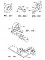
- FIG. 1Aillustrates a schematic, top-level view of a robotic instrument system 2 according to one embodiment.
- FIGS. 1B-1Fillustrate various other embodiments of a system 2 that may utilize a mechanical ditherer 50 or other dithering mechanism or device as described herein.
- FIG. 1Billustrates a manually-operated, steerable guide catheter 500 that is mounted via a base 24 containing a ditherer 50.
- the ditherer 50is coupled to a working instrument 30 that is dithered back-and-forth relative to the guide catheter 500.
- the working instrument 30may include any number generally elongate members that are typically used during medical diagnostic or therapeutic procedures.
- the working instrument 30may include by way of illustration and not limitation, a catheter, guide wire, imaging element, laser fiber or bundle of fibers, tool, or other instrument.
- FIG. 1Cillustrates a ditherer 50 used in conjunction with a relatively rigid elongate member such as, for example, a trocar 600.
- the ditherer 50is coupled to a working instrument 30 that is dithered in a reciprocating fashion through a lumen (not shown) contained in the trocar 600.
- a base 24is used to secure the ditherer 50 relative to the trocar 600.
- FIG. 1Dillustrates still another embodiment in which the ditherer 50 is coupled to a working instrument 30 that is passed through a tool 700 which may include a rigid or semi-rigid shaft having one or more lumens therein adapted to receive a working instrument 30.
- the tool 700may be coupled to a housing 702 that mechanically and electrically couples the tool 700 to a robotically-controlled manipulator.
- the tool 70may be coupled to a robotically controlled instrument driver such as, for instance, the DA VINCI surgical system sold by Intuitive Surgical, Inc. of Sunnyvale, California.
- FIG. 1Eillustrates an embodiment in which a working instrument 30 such as an endoscope is coupled to the ditherer 50.
- the working instrument 30can thus be moved relative to an outer flexible member such as a segmented, flexible scope 800 of the type developed by NeoGuide Systems, Inc.
- FIG. 1Fillustrates still another embodiment in which, for example, the ditherer 50 is used in connection with visualization tool such as an endoscope 900.
- the ditherer 30is coupled to a working instrument 30 such as a guide wire that is dithered back-and-forth with respect to the endoscope 900.
- the endoscope 900may be rigid, flexible, or semi-rigid.
- the depicted robotic instrument systemcomprises a robotically-steerable guide instrument 4 and an outer sheath instrument 6 which may also be robotically-steerable.
- a systemcomprising both a flexible robotic guide instrument 4 and a flexible robotic sheath instrument 6, each of which may also be termed a variation of a steerable "catheter", as described in the aforementioned applications, is depicted, although variations comprising only a flexible robotic guide instrument 4 or only a flexible robotic sheath instrument 6, as accompanied by a flexible working instrument 30 as described below, may be desired.
- non-steerable and/or non-flexible or semi-flexible instrument set configurationsfor example, to sense forces at the distal end of a working instrument advanced through a straight or bent, rigid, flexible, or semi-flexible steerable or nonsteerable trocar, or other straight or bent, rigid, flexible, or semi-flexible, steerable or nonsteerable minimally invasive instrument defining a working lumen in which a working instrument may be moved in an oscillatory fashion - such as the robotic instruments available from manufacturers such as NeoGuide Systems, Inc., Stereotaxis Inc., and Intuitive Surgical, Inc.).
- dithering-based force sensing technologies described hereinmay be utilized in other applications with non-slender, or non-minimally-invasive, instruments, so long as such instruments define a lumen through which a working instrument may be moved in an oscillatory fashion and detected, as described below.
- robotic steering actuationis provided to the sheath and guide instruments in the depicted embodiment by a robotic instrument driver 400.
- Both the guide instrument 4 and sheath instrument 6define respective lumens 8, 10, and in the depicted configuration, the sheath instrument 6 coaxially surrounds a portion of the guide instrument 4.
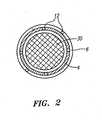
- the robotically-steerable guide instrument 4 and sheath instrument 6comprise a number of control members 12, as shown in the cross-sectional view of FIG. 2 , that may be used to steer the guide instrument 4 and/or sheath instrument 4 using actuations from the robotic instrument driver 400.
- the control members 12may comprise wires or the like that are selectively tensioned via respective proximal instrument portions or "splayers" 14, 16 that are configured to be interfaced with the robotic instrument driver 400 to provide steering actuation to the guide instrument 4 and sheath instrument 6, along with insertion or retraction a long the longitudinal axis of the proximal lumen defined by the guide instrument 4 or sheath instrument 6 via motors within the instrument driver 400 which are configured to insert and retract the splayers 14, 16 independently relative to each other and relative to the outer structure of the instrument driver 400 and/or relative to the operating table.
- splayersselectively tensioned via respective proximal instrument portions or "splayers" 14, 16 that are configured to be interfaced with the robotic instrument driver 400 to provide steering actuation to the guide instrument 4 and sheath instrument 6, along with insertion or retraction a long the longitudinal axis of the proximal lumen defined by the guide instrument 4 or sheath instrument 6 via motors within the instrument driver 400 which are configured to insert and
- the guide splayer 14 and sheath splayer 16may comprise a plurality of motor-driven, rotating spools or drums (not shown) that can selectively tension or release the control members 12 of the pertinent instrument to provide controlled steering to the guide instrument 4 and/or sheath instrument 6.
- the splayers 14, 16may also move longitudinally ("insertion” or “retraction") with respect to the robotic instrument driver 400 main structure as illustrated with arrows "A" in FIG. 1A .
- the guide instrument 4passes through the lumen 10 of the sheath instrument 6 and is thus moveable with respect thereto.
- the distal end 18 of the guide instrument 4projects distally with respect to the distal end 20 of the sheath instrument 6.
- the guide instrument 4may be withdrawn proximally such that the distal end 18 is substantially flush with the distal end 20 of the sheath instrument 6, or withdrawn proximally even further such that the distal end 18 is hidden within the distal end 20 of the sheath instrument.
- the contact surfaces between the guide instrument 4 and the outer sheath instrument 6may be coated with a lubricous coating such as, for example, PTFE to reduced frictional forces there between.
- an optional flushing fluidmay be pumped or forcibly moved between the guide instrument 4 and outer sheath instrument 6.
- the flushing fluidmay act as a lubricant in addition to preventing retrograde flow of blood and other biological material into the space between the guide instrument 4 and outer sheath instrument 6.
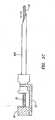
- FIG. 1Aa working instrument 30 is shown being secured to the robotic instrument driver 400.
- the working instrument 30may comprise any number of types of instruments, including but not limited to guidewires, probes, laser fibers, injection devices, surgical tools, and catheters, such as electrophysiology catheters, ablation catheters, and the like.
- FIG. 1Aillustrates an ablation catheter as the working instrument 30 with electrodes 32 positioned at a distal end 34 of the ablation catheter.
- the working instrument 30, or "working catheter" in this instancemay be custom designed for use with the robotic instrument system 2 or, alternatively, the working instrument 30 or working catheter may comprise an off-the-shelf catheter such as those used by physicians in conventional, manually-navigated procedures.
- the working instrument 30is loaded into the robotic instrument system 2 by passing the distal end 34 through a seal 40.
- the seal 40may comprise a "Touhy" that has a small hole or opening through which the working instrument 30 passes.
- the Touhy seal 40may have an elongate or rigid body with a proximal end cap 44 (seen e.g., in FIGS. 13 , 14 , 16 , and 17 ) or the like that is used to create a non-slip, fluid-tight seal between the Touhy 40 and the working instrument 30.
- the Touhy seal 40is secured to a mechanical "ditherer" 50 via a clamp 54.
- the mechanical ditherer 50is a mechanical subsystem that moves in a reciprocating or oscillating motion in the direction of arrow B, and may be coupled to other structures, such as a working instrument, to induce oscillatory, reciprocating, or "dithering" motion in such other structures.
- the mechanical ditherer 50is driven by a motor (not shown in FIG. 1 A) which may be located on-board the robotic instrument driver 400 or, in other embodiments, off-board the robotic instrument driver 400 as a separate dithering actuation subsystem.
- the mechanical ditherer 50dithers or causes reciprocating axial movement of the working instrument 30 relative to the guide instrument 4 and sheath instrument 6.
- FIG. 1Aillustrates the distal end 34 of the working instrument 30 dithering back and forth in the direction of arrow "C".
- the length or stroke of the ditheringmay be adjusted depending on the nature of the procedure but generally is less than a few millimeters. In some embodiments, the stroke of the dithering may be less than about 1.5 mm.
- the mechanical ditherer 50comprises at least one force sensor (not shown in FIG. 1A ) that is used to detect the force or load that is being applied to the proximal portion of the working instrument 30.
- the force sensorsare able to determine the insertion and withdrawal forces applied to the working instrument 30 via the mechanical ditherer 50. Over one or more dithering cycles, these force profiles or waveforms can be used to accurately estimate contact forces at the distal end 34 of the working instrument 30.
- FIG. 1Ashows the distal end 34 in close proximity to an anatomical surface 70 which may comprise, for instance, cardiac tissue.
- contact forcesmay also come from other objects in the vicinity of the distal end 34 such as, for instance, medical instruments or the like.
- a flexible bellows 60connects the distal end of the Touhy seal 40 to the proximal end of the guide instrument 4.
- the flexible bellows 60compresses and expands as the working instrument 30 is dithered with respect to the guide instrument 4 and sheath instrument 6.
- the flexible bellows 60may be connected to a fluid line 64 that is connected to a source of pressurized saline or the like.
- the pressurized salineis pumped into the space between the exterior of the working instrument 30 and the interior of the guide instrument 4 to prevent backflow of blood or other bodily fluids which, if allowed to retrograde into the guide instrument, could disrupt the ability to dither the working instrument 30 inside the guide instrument 4.
- Additional fluid lines 66, 68may be coupled, respectively, to the guide instrument splayer 14 and sheath instrument splayer 16 to provide lubrication between guide instrument 4 and sheath instrument 6.
- FIG. 1Aillustrates the mechanical ditherer 50 being coupled to the Touhy seal 40 it should be understood that the mechanical ditherer 50 also may be coupled directly to a proximal region of the working instrument 30.
- FIG. 1Aalso illustrates a second clamp 58 that is used to secure the handle 36 of the working instrument 30 to the robotic instrument driver 400. In this regard, inadvertent movement of the handle 36 does not affect the force sensing capabilities of the mechanical ditherer 50.
- the handle 36is isolated or grounded from the load sensing aspect of the mechanical ditherer 50 which is discussed in more detail below.
- the repeated cyclic motionmay be utilized to overcome frictional challenges normally complicating the measurement, from a proximal location, of loads at the distal end 34 of the working instrument 30 when in contact with a surface.
- the dithering motionmay be applied on a proximal region of the working instrument 30 as is illustrated in FIG. 1A and near the location at which relative axial load is measured.
- dithering motionmay be used to effectively break loose this frictional coupling.
- the dithering motionmay be applied on a proximal region of the working instrument 30.
- both the guide instrument 4 and working instrument 30may be dithered with respect to one another.
- FIG. 1Aillustrates longitudinal dithering of the working instrument 30 with respect to the guide instrument 4. It is possible in alternative embodiments to dither the working instrument 30 radially with respect to the guide instrument 4. Alternatively, the guide instrument 4 could be dithered radially with respect to the working instrument 30. In yet another alternative, the guide instrument 4 and working instrument 30 could both be dithered in the radial direction at the same time.
- the dithering embodiment illustrated in FIG. 1Aavoids some of the complexities associated with using custom-made working instruments having embedded, distally-located sensors and instead facilitates the use of standard off-the-shelf working instruments 30.
- the working instrument 30without altering the working instrument 30, by dithering the proximal region of the working instrument 30, either directly or via the seal 40, and placing the force sensors at the proximal region of the working instrument 30 it is possible to measure the estimated force that is applied at the distal end 34 of the working instrument 30.
- By dithering the working instrument 30,the same is in motion substantially all of the time, and applied forces are shown in the force readings as incremental forces, thus substantially eliminating the effects of static friction after data processing has been executed, which is described in more detail below.
- the robotic instrument system 2may comprise an all stop button 74 that is used to terminate activity of the robotic instrument driver 400 when depressed.
- the button 74thus acts as a safety feature should one or more aspects of the device fail requiring manual user intervention.
- FIG. 1Aalso illustrates a user interface 80 that is operatively connected to the robotic instrument driver 400 and instrument set.
- the physician or other userinteracts with the user interface 80 to operate the robotic instrument driver 400 and associated guide 4 and/or sheath 6 instruments, and associated working instrument 30.
- the user interface 80may be connected to the robotic instrument driver 400 via a cable or the like.
- the user interface 80may be located in a geographically remote location and communication is accomplished, at least in part, over a wide area network such as the Internet.
- the user interface 80may also be connected to the robotic instrument driver 400 via a local area network or even wireless network that is not located at a geographically remote location.
- FIG. 1Aalso illustrates a display 90 that is used to display various aspects of the robotic instrument system 2.
- a display 90may be displayed in real time on the display 90 to provide the physician with the current orientation of the various devices as they are positioned, for example, within a body lumen or region of interest.
- the display 90may include a readout on the estimated force experienced by the distal end 34 of the working instrument 30.
- the readoutmay include graded scale 92 with a moveable arrow 94 that rises or falls as the force changes.
- the display 90may also include a visual cue 96 indicating the amount of error associated with the estimated force.
- the visual cue 96may include error bars as shown in FIG. 1A .
- the visual cue 96may include a separate scale or graph that illustrates real time error in the measured force.
- the visual cue 96may also include a color change to the arrow 94.
- the visual cue or graphical element 96may include a warning indicator or textual message.
- the display 90may include a visual cue or signal that is present when the error exceeds a pre-determined threshold value (e.g., +/- 20% or +/- 20 grams).
- a pre-determined threshold valuee.g., +/- 20% or +/- 20 grams.
- the estimated measured force at the distal end 34 of the working instrument 30may also be compared with a pre-determined threshold value. For example, if too much pressure is being applied to the distal end 34, an audible warning signal may be initiated.
- a visual signalsuch as a graphical element 98 may be shown on the display 90.
- a haptic signalmay be returned to the user, for example, a vibrational signal that can be felt by the user.
- FIG. 3illustrates a user interface 80 located at an operator control station 82 located remotely from an operating table 84 having a movable support-arm assembly 86.
- the support assembly 86is configured to movably support the robotic instrument driver 400 above the operating table 84 in order to position the guide instrument 4, sheath instrument 6, and working instrument 30 (not shown in FIG. 3 ).
- a communication link 86transfers signals between the operator control station 82 and the robotic instrument driver 400.
- FIG. 4a view of another variation of an operator control station 82 is depicted having three displays 90, a touch screen user interface 100, and a control button console 102.
- the control button console 102may comprise a button 103a that is used to turn the force sensing capability on or off.
- the control button console 102may comprise a dedicated button 103b that is used to baseline the robotic instrument driver 400 or associated instrument set. Of course, these functions may be implemented instead via the touch screen user interface 100.
- the operator control station 82comprises master input device 104 that is manipulated by the physician to translate movement to the robotic instrument driver 400 and associated instruments.
- a device disabling switch 106configured to disable activity of the instrument temporarily.
- the cart 108 depicted in FIG. 4is configured for easy movability within the operating room or catheter lab, one advantage of which is location of the operator control station 82 away from radiation sources, thereby decreasing radiation dosage to the operator.
- FIGS. 5-11illustrate schematically various methods of accomplishing force estimation at the distal end 34 of a working instrument 30 by using a dithering technique.
- FIG. 5illustrates an embodiment in which the working instrument 30 dithers with respect to substantially stationary guide instrument 4.
- the mechanical ditherer 50will drive the working instrument 30 through a force sensor 110 which will measure the direct force needed to insert and withdraw the working instrument 30 in and out of the guide instrument 4.
- the ditherer 50is mechanically grounded (via a mechanical linkage 52) to a proximal region 35 of the guide instrument 4 and is thus stationary to the guide instrument 4 but the force sensor 110 and working instrument 30 move together relative to the guide instrument 4. Readings from the force sensor 110 may be sent through conditioning electronics 114 then to a computer 118 for data processing, and finally to a display 122.
- FIG. 6illustrates an alternative embodiment in which the ditherer 50 and force sensor 110 are mechanically linked to a seal 40 such as a Touhy seal.
- the Touhy seal 40acts as a fluidic seal which can add significant and erratic drag to the reciprocating in-and-out motion of the working instrument 30 which would adversely affect the accuracy of readings from the force sensor 110.
- the embodiment of FIG. 6eliminates this effect by mechanically securing or locking the Touhy seal 40 to the working instrument 30 so the two are dithered together.
- FIG. 6illustrates the flexible bellows 60 that is connected to the proximal end of the guide instrument 4 at one end and secured to the Touhy seal 40 at the other end.
- the bellows 60includes a flush line 64 that is used to delivery pressured saline as described herein.
- the bellows 60expands and contracts like an accordion with the dithering motion.
- the bellows 60advantageously applies a very low drag force on the working instrument 30 during the dithering motion as opposed to the high drag force that would be applied if the working instrument 30 was dithered through the Touhy seal 40.
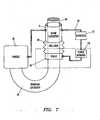
- FIG. 7illustrates yet another embodiment which further secures or grounds a handle 36 of the working instrument 30.
- disposable working instruments 30, such as the ablation catheters available from such suppliers as Boston Scientific and Biosense Webster under trade names such as "BlazerTM” and "NaviStarTM”are typically manufactured with a handle 36 located on their proximal end. Unsecured, this handle 36 would likely apply forces on the Touhy seal 40 and/or working instrument 30 that would be read by the force sensor(s) 110 and perhaps mistakenly be interpreted as applied forces at the distal end 34 of the working instrument 30. Because of this, in the embodiment illustrated in FIG. 7 , the handle 36 is isolated or guarded from the Touhy seal 40 and the force sensor(s) 110. The “guarding” may be accomplished by securing the instrument handle 36 into a holder such as the clamp 58 as shown in FIG. 1A .
- the handle 36may be grounded in one of a number of ways. One variation is to physically ground the handle 36 to the guide instrument 4 as shown in FIG. 7 . In this case the handle 36 would be stationary relative to the guide instrument 4. As another alternative, the handle 36 may be grounded to a common carriage or mounting plate on which the guide and sheath instrument splayers 14, 16 are mounted. In this configuration the handle 36 is again grounded with respect to the guide instrument 4 albeit indirectly via a common carriage or mounting plate.
- FIG. 8illustrates another embodiment in which the handle 36 is secured to the mechanical ditherer 50 via a securing member such as a clamp.
- the handle 36would dither along with the Touhy seal 40 and the working instrument 30. It is important to note that the force used to dither the handle 36 back and forth does not go through the force sensor(s) 110 and so any forces needed to move the handle 36 (or any accidental forces applied to the handle 36) are not seen by the force sensor(s) 110. Consequently, in this case, the handle 36 would be completely guarded within the system and there would be no periodic offset force.
- a drape 130may be used to isolate non-sterile equipment from the sterile, surgical environment.
- the drape 130may cover the ditherer 50. If the drape 130 is attached to the force sensor(s) 110 and happens to catch on a person or equipment, it may pull on the force sensor(s) 110 and add an unwanted force measurement (e.g., artifact). Because of this, the portion of the drape 130 that is around the force sensor(s) 110 preferably is guarded - in this case by attaching it to a rigid ring 132, comprising materials such as metals or polymers, that surrounds the force sensor(s) 110 and Touhy seal 40. The guard ring 132 may be attached to the system with any number of methods.
- the ring 132is attached to a point where the drape 130 dithers along with the working instrument 30.
- accidental pulls on the drape 130generally are not transferred into the force sensor(s) 110 (but is transferred to the ditherer 50) and preferably does not result in a false force measurement.
- FIG. 10Another variation is illustrated in which the drape guard ring 132 is secured to the guide instrument 4. Consequently, an accidental pull on the drape 130 (outside of the drape guard ring 132) advantageously is transferred into the stationary guide instrument 4 and not into the force sensor(s) 110.
- the Touhy seal 40 and/or force sensor(s) 110which is dithered
- the stationary guard ring 132which will may cause bunching and stretching of the drape 130 inside the guard ring.
- the drape 130preferably is very compliant and this differential motion causes a small amplitude periodic force which is substantially the same during insertion and withdrawal and may thus be subtracted in subsequent force sensing data processing.
- FIG. 11illustrates one embodiment of a drape 130 that is shown loaded onto a robotic instrument driver 400.
- the drape 130includes platform covers 134 having a series of holes which are used to mount the splayers 14, 16.
- proximal of the platform cover 134 for the guide instrument splayer 14is a flexible boot 136 made of a very flaccid rubber or polymeric material that is surrounded by a ring 133 of semi-rigid material.
- the ring 133is secured to the robotic instrument driver 400 such that any pulling, tugging, or other forces are transmitted through the drape 130 to the robotic instrument driver 400 and not the flexible boot 136.
- the semi-rigid ring 133may be secured to the grounded drape ring 132.
- the boot 136 and ring 133isolate forces on the drape 130 from affecting the force measurements obtained using the force sensors 110.
- the working instrument 30passes through the flexible boot 136 and can be secured to the ditherer 50.
- a different variation of ditheringcomprises dithering the working instrument 30 rotationally as opposed to longitudinally or axially.
- the force sensor(s) 110would no longer be in series with the mechanical ditherer 50. Rather, the ditherer 50 would in this case be rotational and because it is an orthogonal motion (relative to the in-and-out motion due to the distal end force which may be applied to the working instrument 30), the orthogonal forces may be isolated from one another by using a bearing 48 allowing the force sensors 110 to measure the applied force at the distal end 34 as isolated from the forces caused by the rotational dithering motion.
- the structure of the flexible bellows 60facilitates the operation of this dithering force measurement system.
- the bellows 60provides low force from the longitudinal dithering and is volumetrically compliant to allow for the change of flush volume within the bellows 60 during the dithering process.
- the bellows 60is configured to allow for rotation of the ends of the bellows 60 while not creating a significant longitudinal force offset to the force sensor(s) 110.
- FIG. 13illustrates a perspective view of a robotic instrument system 2 according to one embodiment of the invention.
- the robotic instrument system 2includes a housing 150 that is partially exposed in FIG. 13 .
- the robotic instrument system 2generally comprises a carriage configured to interface with structures coupled to or comprising the guide instrument splayer 14, and a carriage configured to interface with structures coupled to or comprising the sheath instrument splayer 16.
- Longitudinal slots 154 defined by the outer housing 150 of the robotic instrument driver 400are configured to facilitate longitudinal movement of the carriages and associated splayers 14, 16 relative to the outer housing 150 of the robotic instrument driver 400
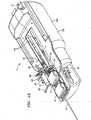
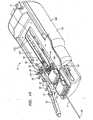
- FIG. 14illustrates a magnified perspective view of the distal portion of the robotic instrument system 2.
- the guide instrument 4 and sheath instrument 6are not shown for clarity purposes.
- the clamp 54 for the Touhy seal 40may comprise a rotatable handle 140 that is used to frictionally hold the Touhy seal 40 in place.
- the clamp 54may comprise a lower seat 156 that is positioned on the load bearing aspect of the ditherer 50 and an upper clamping member 158 that, when tightened via the handle 140, frictionally secures the Touhy seal 40 in a sandwich arrangement.
- the handle 140may comprise a groove or notch 142 that can be used to temporarily secure a flush line or the like.
- FIG. 14also illustrates a clamp 58 for the handle 56 of the working instrument 30 that also comprises a rotatable handle 144 that is used to frictionally secure the handle 36 of the working instrument 30 in place.
- the clamp 58may comprise a lower seat 160 that is fixedly secured to the carriage (or a support member secured to the carriage) and an upper clamping member 162 that, when tightened via the handle 144, frictionally secures the proximal handle 36 in a sandwich arrangement.
- the rotatable handle 144comprises a groove or notch 146 that can be used to temporarily secure a flush line or the like.
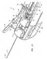
- FIG. 15illustrates an assembly drawing of the guide instrument splayer 14 along with the mechanically coupled mechanical ditherer 50.
- a working instrument 30is shown being inserted into the proximal end of the Touhy seal 40.
- the distal end 34 of the working instrument 30is not shown in FIG. 15 .
- the Touhy seal 40 of FIG. 15illustrates a proximal end having a series of threads 42 on which is mounted a cap 44 which is illustrated in, for example, FIGS. 13 , 14 , 15 (showing threads 42), 16, and 17).
- the cap 44may be tightened on the threads 42 to form a fluidic seal that prevents fluid from escaping between the interface of the seal 40 and the working instrument 30.
- FIG. 13 , 14 , 15shows threads 42
- conduit 65that is connected to the interior of the Touhy seal 40.
- the conduit 65is connected to a source of pressurized flush solution 76 which may comprise, for instance, pressurized saline.
- a pressure regulator 78 or the likemay be interposed in the conduit 65 between the pressurized flush solution 76 and the Touhy seal 40 to ensure that a constant pressure of fluid is applied.
- the conduit 65may be fluidically coupled to the flexible bellows 60.
- FIGS. 16 and 17illustrate perspective views of the robotic instrument system 2 having a working instrument 30 being inserted into the Touhy seal 40.
- the working instrument 30passes through the lumen 8 of the guide instrument 4 and the lumen 10 of the sheath instrument 6.
- the handle 36 of the working instrument 30is secured to the robotic instrument driver 400 via the clamp 58.
- FIGS. 16 and 17also illustrate a flush line or conduit 65 that is held in place via the groove 146 in the handle 144.
- the working instrument 30,which in certain embodiments may include an off-the-shelf steerable or nonsteerable catheter, may include a steering member 31 located on the handle 36. In this case, the steering member 31 is preferably placed into a neutral position to permit steering by the robotic instrument driver 400.
- FIGS. 18A-Cillustrate various aspects of the mechanical ditherer 50 according to one embodiment.
- FIG. 18Aillustrates a guard ring or cage 170 that is mounted to a moveable dither carriage 180 (as seen in FIGS. 18B and 18C ).
- the guard ring 170may be secured via mounting pads 172 having holes therein for passage of a screw, bolt, or the like (not shown) that mates with respective holes 182 in the dither carriage 180.
- the guard ring 170may include additional holes 176 on a top surface thereof for mounting, for example, the drape 130. In this regard, the drape 130 dithers along with the working instrument 30. Any accidental pull on the drape 130 would not be transferred into load cells and would not result in a false force measurement.
- FIG. 18Billustrates the load bearing member 190 of the mechanical ditherer 50.
- the load bearing member 190is pivotally mounted to the dither carriage 180.
- the load bearing member 190pivots about pivot point 192 in the manner of an inverted pendulum.
- the pivot point 192may include a shaft 194, pin, bearing or the like that permits dithering movement of the load bearing member 190 along with the dither carriage 180.
- the dithering motioncauses movement of the dither carriage 180 and attached load bearing member 190 in the direction of arrow A in FIG. 18B .
- Two load cells 200(one of which is illustrated in FIG. 18B ) are positioned on either side of the load bearing member 190 and each contain a force sensor 204.
- FIG. 18Billustrates the load bearing member 190 of the mechanical ditherer 50.
- the load bearing member 190is pivotally mounted to the dither carriage 180.
- the load bearing member 190pivots about pivot point 192 in the manner of an in
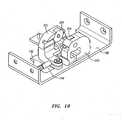
- FIG. 19illustrates a perspective view of the dither carriage 180 including the load cells 200 having the respective force sensors 204 loaded therein.
- the load bearing member 190is fixedly secured to the dither carriage 180 via the pivot point 192 and moves along therewith during the dithering movement.
- the two force sensors 204measure compressive forces. In particular, the two force sensors 204 output a small voltage that is proportional to or correlates with the applied force.
- the load bearing member 190comprises the seat 156 onto which is mounted the Touhy seal 40 (or in other embodiments the working instrument 30). As the dither carriage 180 is moved back and forth in the reciprocating manner, the forces experienced on the proximal end of the working instrument 30 (or Touhy seal 40) are then measured via the output signals on the two force sensors 204.
- the load bearing member 190which swings back-and-forth in a pendulum-like manner, alternatively makes contact with the opposing force sensors 204. When the load bearing member 190 does not contact a force sensor 204, the force sensor 204 outputs a baseline or zero signal (e.g., no voltage).
- the analog voltage signal from each force sensor 204is amplified via an amplifier (not shown).
- the amplified signalmay then pass through a flex circuit on the robotic instrument driver 400 structure to one or more circuit boards (not shown) mounted to the carriage or chassis.
- the analog signalthen is transformed into a digital signal via an analog-to-digital converter (ADC).
- ADCanalog-to-digital converter
- the digital signalscan then be passed to an off-board computer located, for example, at the operator control station 82.
- the operator control station 82may then convert the digital data into a usable form using, for example, the single cycle subtraction algorithm described in more detail below.
- the separation of the load cells 200is dimensioned such that there is a relatively small gap between the load cells 200 and the load bearing member 190 as there is a small dead band created when the load bearing member 190 is not touching either of the two opposing force sensors 204.
- the dither carriage 180is secured to two c-shaped channels 184.
- the channels 184engage with correspondingly dimensioned rails (not shown) such that the entire dither carriage 180 is able to move back-and-forth in the direction of arrow A in FIG. 18B .
- FIG. 20schematically illustrates the load bearing member 190 moving about pivot point 192 between the opposing load cells 202 holding the force sensors 204.
- the pivot point 192may include a stationary shaft 194 that is mounted with respect to the opposing load cells 202.
- the shaft 194may be driven through the base of both load cells 202.
- the load bearing member 190is sandwiched between the two load cells 202 and is held on the shaft 194 via bearings 196 or the like that allows rotational motion of the load bearing member 190 pivot about the shaft 194.
- the mechanical ditherer 50will dither the load cells 200 back and forth (in a linear displacement fashion approximately 1.5 mm from peak-to-peak). Of course other stroke lengths are also contemplated.
- the load bearing member 190rotates a very small amount to exchange force from one force sensor 206 to the other force sensor 206 then the linear motion of the ditherer carriage 180 continues to carry the load bearing member 190 in a linear motion which pushes in or pulls out the working instrument 30.
- the load bearing member 190acts as a static lever arm.
- eachcan be used to verify that the other force sensor 204 is working properly. For example, the dead band zone where the load bearing member 190 is not touching either force sensor 204 occurs once per dither cycle and is used to confirm the force sensor 204 "zero load" position and to test proper force sensor 204 operation.
- the load cell mounts 200are designed to protect the force sensors 204 from excessive forces from the load bearing member 190 (excessive forces applied to a force sensors 204 may permanently damage them leading to incorrect force readings).
- the load cell mounts 200may have a precision ground cup into which the force sensor 204 sits. The depth of this cup may be just slightly shorter than the height of the force sensor 204 sitting in it, so that as the load bearing member 190 rotates to the force sensor 204 and load cell mount 200 it will push on the force sensor 204 at first.
- the force sensor 204(which has a very slight amount of compliance) reduces in height until the load bearing member 190 strikes the load cell mount 200.
- the maximum force applied to the force sensor 204can be set, which will protect the force sensor 204 excessive forces.
- Other methods of protecting the force sensors 204can be achieved by using shims or fine pitched screws to adjust for the point where forces to the force 204 are shunted anyway.
- the force sensors 204themselves may be uni-directional compression force sensors (sometimes referred to also as load cells) rated at 5 lbs (e.g., available from Honeywell Sensotec-Lebow of Ohio).
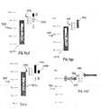
- FIGS. 21A and 21Billustrate an exemplary waveform of the measured or observed forces using the force sensors 204 through a single dither cycle.
- the single dither cycleincludes a single insertion stroke followed by a single withdrawal stroke. Positive forces are those measured during insertion while negative forces are those measured during withdrawal.
- one force sensor 204is used to measure insertion forces while the other, opposing force sensor 204 is used to measure withdrawal forces.
- the applied forceincreases in a substantially linear manner until the force plateaus. The point at which the force begins to plateau is taken at that point when the working instrument 30 begins to dither axially with respect to the guide instrument 4. After a period of constant or substantially constant force, the force then begins to decrease in a substantially linear manner. The force then goes "negative” as the working instrument 30 is withdrawn from the guide instrument 4. The force then plateaus at a negative value before returning to the origin.
- FIG. 21Aillustrates a condition in which no force is applied to the distal end 34 of the working instrument 30.
- FIG. 21Aillustrates two such waveforms (solid line 210 and dashed line 212). Both waveforms, while having different amplitudes, are substantially symmetrical. This feature is particularly advantageous because the forces are symmetrical in nature, the resulting waveform shows an equal force on insert and on withdrawal. Consequently, in processing the obtained force measurement data from the force sensors 204, it is possible to take a one cycle average of the waveform that will eliminate the substantially symmetrical offset forces from the measurement leaving only the differential shift in force.
- This differential shift in forceis the force that is applied at the distal end 34 of the working instrument 30. Consequently, measured or observed forces at the proximal region 35 of the working instrument 30 may be used to accurately and consistently estimate forces applied to the working instrument 30 at the distal end 34.
- FIG. 21Billustrates a first or "baseline” waveform 216 (solid line) taken when no force is applied to the distal end 34 of the working instrument 30.
- FIG. 21 Balso shows the waveform 218 (dashed line) taken when a force is applied to the distal end 34 of the working instrument 30.
- the entire curveis shifted in the upward direction.
- the amplitude d1is now larger than the amplitude d2. This difference between the baseline measurement and the measurement obtained upon application of a force may be used to quantify the force applied to the distal end 34 of the working instrument 30.
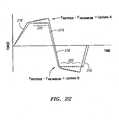
- FIG. 22illustrates a baseline waveform 216 (dashed line) along with an overlaid waveform 218 (solid line) obtained when a force is applied to the distal end 34 of a working instrument 30.
- a portion 220 of the plateau region of both the baseline waveform 216 and the waveform 218 created from the contact forceare sampled in regular increments.
- the force readouts from the sensors 204may be sampled at one millisecond increments over their entire cycle. While the entire waveform may be sampled, different embodiments may choose to ignore portions of the sampled waveform.
- only those portions 220 of the plateausare kept or utilized for the force algorithm with the remaining readout figures being ignored or deleted.
- the portion 220 of the waveform plateaumay include a partial segment of the waveform that eliminates the endpoints as is shown in FIG. 22 .
- baseline force measurementsare obtained at the baseline sampling locations in the plateau regions 220 for both the insertion stroke and the withdrawal stroke with no force applied on distal end 34 of working instrument 30.
- An average force measurementis then obtained for each binned series of baseline data for both the insertion and withdrawal strokes.
- the average force measurements within the plateau regions 220may be averaged over a number of cycles, for example, three cycles.
- sampled force measurementsare also obtained over the plateau regions 220 with the working instrument 30 being subject to a force on the distal end 34. Force measurements obtained over the binned insertion period are then averaged and subtracted from the average baseline force described above to produce an Update A value.
- the Update A valuecorresponds to the difference of the average forces obtained from the working instrument 30 under the insertion stroke with force applied and under insertion stroke with no force applied (i.e., baseline). Similarly, force measurements obtained over the binned withdrawal period are then averaged and subtracted from the average baseline withdrawal force described above to produce an Update B.
- Update Ais determined at the completion of the insertion portion of the stroke while Update B is determined at the completion of the withdrawal portion of the stroke.
- the values(Update A or Update B) are updated about every 1 ⁇ 4 second.
- Update Ais updated, then Update B, then Update A, and so on and so forth.
- the force valueis re-calculated.
- a dither ratemay be altered as needed.
- the dither ratemay vary between 0 Hz and about 10 Hz.
- the algorithm described aboveuses a single cycle differential average of selected portions of the waveforms obtained during a contact state and a non-contact state there are other ways of obtaining similar information.
- the averagesmay be calculated over more than one cycle.
- the estimated forcemay be obtained by comparing the profile or shape of the measured waveforms when the working instrument is in a contact state (e.g., experiencing a force) with the measured waveform obtained in a baseline state (e.g., no force).
- a contact statee.g., experiencing a force
- a baseline statee.g., no force
- waveform sloperepresentative of mechanical stiffnesses in the system, as an indicator for which portion of the waveform contains useful data (i.e., signal) and which portion of the waveform is superfluous (i.e., noise).
- FIG. 23illustrates a perspective view of a chassis 230 on which the guide splayer 14 (not shown) is mounted.
- FIG. 23further illustrates the pivotable lever arm 232 that mechanically connected to the dither carriage 180.
- the lever arm 232includes a hole 234 for receiving a bearing 236 that is mounted to a surface (e.g., top surface) of a pulley 238.
- the lever arm 132pivots about pivot point 240 which is the rotational axis of the bearing 236.
- the lever arm 232further includes a slot 242 that traverses a portion of the length of the lever arm 232.
- the slot 242is dimensioned to receive a bearing 244 mounted in an eccentric manner on a pulley 246.
- the bearing 244is mounted in an eccentric or offset manner by using a cam 248 that is affixed to the upper surface of the pulley 246 by, for instance, screws 250.
- the cam 248may be "T-shaped" and include a pin or shaft 249 on which the bearing 244 is mounted. Different cams 248 having different distances between the center of rotation of the pulley 246 to the pin 249 may be used to alter the degree of eccentricity. This, in turn, would alter the stroke distance of the mechanical ditherer 50.
- the lever arm 232includes another slotted portion 252 in a central region of the lever arm 232.
- the slotted portion 252is generally oriented longitudinally along the length of the lever arm 232.
- the slotted portion 252is dimensioned to receive a bearing 254 this is rotationally mounted to the dither carriage 180.
- the bearing 254may be positioned on a mount 256 that elevates a portion of the dither carriage 180.
- the dither carriage 180is mounted to the chassis 230 using two crossed roller slides 258.
- the crossed roller slides 258includes a base 260 that is fixedly secured to the chassis 230 and an inner slidable carriage 262 that is coupled to the dither carriage 180.
- a series of bearings or cylindrical steel rollers(not shown) enables the carriage 262 to glide, almost friction-free, over the base 260.
- the cross roller slides 258may be obtained from Del-Tron Inc., 5 Trowbridge Drive, Bethel, CT 06801 (model no. RD-1).
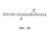
- the pulleys 238, 246 used to drive the lever arm 232include a circumferential groove 266 that is used to hold a drive cable 270 (shown in FIG. 25 ).
- the drive cable 270may be formed from a bundle of numerous smaller wires formed from, for example, tungsten.
- the drive cable 270may have an 8 x 19 construction formed from 152 wires having a diameter of .008" that results in a drive cable 270 having an overall diameter of around .018.”
- the pulleys 238, 246also include a plurality of recesses 268 that formed in the groove 266 and are used to mate with regular spaced crimp balls 272 that located along the length of the drive cable 270. The use of the crimp balls 272 along with the mating recesses 268 ensures that there will be no slippage between the drive cable 270 and the pulleys 238, 246 during the dithering process.
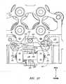
- FIGS. 26 and 27illustrate top down plan views of the lever arm 232 and ditherer 50 as the lever arm 232 is pivoted back and forth in the withdrawal and insertion strokes.
- FIG. 26illustrates the eccentrically offset bearing 244 in roughly a "six o'clock" position wherein the lever arm 232 is at or near the maximal displacement in the proximal direction. The lever arm 232 in FIG. 26 is thus at the beginning of the insertion stroke or, alternatively, the end of the withdrawal stroke.
- FIG. 27illustrates the eccentrically offset bearing 244 in roughly a "twelve o'clock" position wherein the lever arm 232 is at or near the maximal displacement in the distal direction. The lever arm 232 in FIG. 27 is thus at the beginning of the withdrawal stroke or, alternatively, the end of the insertion stroke.
- a motor driven pulley system 280is used to pivot the lever arm 232 back and forth which, in turn, causes the reciprocating motion of the mechanical ditherer 50.
- the drive cable 270is secured to a motor 282 having positioned thereon a drive pulley 284.
- the drive pulley 284is secured to a shaft 283 of the motor using a clamp 287.
- the motor 282is secured to, for example, a chassis 285 of the robotic instrument driver 400.
- the motor 282may be mounted so as to be stationary with respect to the chassis 230 holding the lever arm 232.
- An encoder 281is affixed to the backside of the motor 282 as seen in FIG. 29 and is used to accurately determine the position of the shaft 283 at any given point of time.
- the pulley system 280may also include a tensioning pulley 288 that is used to provide a biasing force, for example, via springs 290, to ensure that the drive cable 270 remains taught.
- the tensioning pulley 288may be used to provide tension to the drive cable 270, for example, if the guide splayer 14 were moved longitudinally.
- the crimp balls 272 positioned along the length of the drive cable 270ensure proper registration between the cable 270 and the various pulleys.
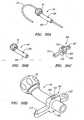
- FIGS. 30A-30G , and FIGS. 31-33illustrate another embodiment of a mechanical ditherer 300.
- a rotationally driven cam 302(best seen in FIGS. 30E and 30G ) is used to drive pivoting holder 304 that is secured to the guide instrument 30 and/or Touhy seal 40.
- FIGS. 30A and 30Billustrate a Touhy seal 40 that includes two tabs or detents 306 that are used to mate with the pivoting holder 304.
- FIG. 30Cillustrates the pivoting holder 304 which includes a hole 307 at one end thereof that is used as the pivot point during operation of the mechanical ditherer 300.
- the holderincludes a main body section 308 that includes an aperture 309 for the Touhy seal 40 along with recesses 310 for the tabs or detents 306.
- the recesses 310serve to properly orient or register the Touhy seal 40 within the pivoting holder 304.
- the pivoting holder 304further includes a pin 312 or other projection that is used to mate with a corresponding groove 314 located in the rotationally driven cam 302, as is shown in FIGS. 30E and 30F .
- the groove 314is spirally cut into the main, cylindrically-shaped body of the cam 302. Different cams 302 having grooves 314 with varying degrees of pitch may be used to adjust the stroke of the ditherer 300.
- FIG. 30Gillustrates the pivoting holder 304 and cam 302 contained in a dither support block 316.
- the pivoting holder 304may be pinned to the dither support block 316 via the hole 307 so as to permit pivoting about the pivot point.
- the cam 302is mounted via a shaft, axle, or the like to supports 318 on the dither support block 316.
- FIG. 30Gfurther illustrates a portion of the working instrument 30 passing through the Touhy seal 40 that is positioned within the pivoting holder 304.
- FIG. 31illustrates a top down view of the ditherer 300 being integrated into the guide instrument splayer 14.
- the Touhy seal 40may be secured at a distal end to a flexible bellows 60.
- the other end of the bellows 60may be coupled to the guide instrument 4.
- a drive cable 320is also shown in FIG. 31.
- the drive cable 320is connected at a proximal end to a motor, servo or the like (not shown) to power the ditherer 300.
- the motor or servomay be located on-board the robotic instrument driver 400 or off-board.
- the drive cable 320may include, for example, a bicycle cable that is rotationally driven back and forth.
- Rotational movement of the drive cable 320may be translated to the cam 302 which, in turn, causes the pivoting holder 304 to pivot back and forth.
- the groove 314is cut in such a manner (e.g., sinusoidal wave) that the cam 302 is rotated in a single direction to cause the back and forth movement of the pivoting holder 304.
- the drive cable 320may be driven in a single direction.
- the driven cable 320may be driven in different directions to cause the cam 302 to rotate in different directions (e.g., clockwise then counter-clockwise).
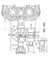
- FIGS. 32A and 32Billustrate a magnified view of the ditherer 300 and its components as it dithers in and out.
- the pivoting holder 304pivots and follows the groove 314 in the cam 302 via the mechanically linked pin 312 (obscured from view).
- the Touhy 40is thus moved back and forth along with the pivoting holder 304.
- the working instrument 30is also securely fastened to the Touhy 40, the working instrument 30 also is dithered back and forth.
- a strain gauge 322may be mounted to the pivoting holder 304 to measure stresses therein so the force on the distal end 34 of the working instrument 30 can be calculated, for example, in the manner described herein.
- FIG. 32Billustrates another embodiment for measuring force.
- force sensors 204are disposed on opposing sides of the supports 318 of the dither support block 316.
- the force sensors 204may include unidirectional force sensors as described herein.
- the displacement of the pivoting holder 304 as well as the distances between the force sensors 204may be engineered to minimize this dead band zone.
- FIGS. 33A-33Gillustrate another embodiment of a mechanical ditherer 330.
- a dither assembly 336includes an electric motor or servo 332 that is used to directly drive a cam 334.
- the direct drive motor 332is mounted to a base 350.
- the electric motor 332directly engages with a cam 334 that has a heart-shaped machined slot 338 as illustrated in FIGS. 33C and 33E .
- a drive linkage 340interfaces with the cam 334 via a pin 342 (best seen in FIG. 33E ) that travels in the cam slot 338.
- the opposing end of the drive linkage 340contains a pin 344 that engages with the pivoting holder 346 that is secured to the Touhy seal 40.
- FIG. 33Gillustrates a base 350 that is used to support the various components of the dither assembly 336. Force measurements may be obtained using either a strain gauge or one or more force sensors as described in the previous embodiment.
- FIGS. 34A - 34Dillustrate various embodiments of how the estimated force at the proximal end 34 of the working instrument 30 is displayed to the physician or user.
- a force scale 400is displayed on, for instance, a display 90 (e.g., FIGS. 3 and 4 ) associated with the operator control station 82.
- the force scale 400may include a number of gradations positioned at regular intervals.
- FIG. 34Aillustrates a force scale ranging from 0 grams to 100 grams of force with gradations every 25 grams.
- the usermay control the scaling of the force scale 400 via a button, switch, menu or the like at the operator control station 82. As seen in FIG.
- the magnitude of the estimated force at the distal end 34 of the working instrument 30 at any particular point in timeis displayed via a bar 402.
- the bar 402rises or falls as the force dynamically changes.
- the bar 402is displayed in real-time or near real time as often as the algorithm described herein is updated.
- a visual cue 404 indicative of the estimated error in the measured forceis also displayed alongside the estimated force.
- the visual cue 404may include an error bar that is displayed alongside its own force scale 406 that indicates the amount of error associated with the particular measurement.
- the error bar 404combines total error with the baseline error on a single force scale 406.
- the visual cue 404may be updated in real-time or near real-time as the algorithm is updated.
- the systemmay be programmed such that if the baseline error goes above a pre-determined threshold value, the user is prompted to re-baseline the device.
- FIG. 34Billustrates an embodiment like that disclosed in FIG. 34A with the difference being that only total error is displayed on the error bar 404 adjacent to the force scale 406 associated with the error visual cue 404.
- FIG. 34Cillustrates another embodiment in which the baseline error and total error are displayed as separate error bars 404a, 404b.
- FIG. 34Dillustrates still another embodiment in which a pointer 408 which, for example, is the form of an arrow or the like is used to display the estimated force.
- the pointer 408dynamically moves up and down as force is applied to the distal end 34 of the working instrument 30. In one aspect, the pointer 408 may get larger as the force increases and, conversely, may get smaller as the force decreases.
- the pointer 408may change color as the force dynamically changes. For example, the pointer 408 may appear to have a "hot" color (e.g., red) if the estimated force is relatively high. In contrast, if there were little or no force experienced by the working instrument 30, the color may be a "cool” color (e.g., blue). An intermediate level of force may be shown using a medium color such as, for instance, yellow. In this regard, the physician is given an extra visual cue as to the forces experienced by the working instrument 30.
- FIG. 34Dalso illustrates a pointer 410 that is used to display the estimated error in the force measurement. Like the force measurement pointer 408, the error pointer 410 dynamically moves as the error changes. The error pointer 410 may also change color in response to the degree of error.
- the estimated errormay be displayed as a force (e.g., grams) or it may be displayed as a percentage or degree of deviation.
- the estimated error that is displayed to the physicianis based on a number of parameters that are empirically determined.
- the estimated errormay be based on the angle of the sheath 6, articulation angle, rate of change of articulation angle, insertion distance, peak-to-peak forces, as well as the magnitude of the forces applied to the distal end 34 of the working instrument 30.
- the estimated errormay also be a function of the type or model of working instrument 30 that is used. This information may be gathered and input via the operator control station 82. Information pertaining to the type of working instrument 30 as well as the empirical data may be stored in a memory or look up table that can then be compared with measured force values to output an estimated error.
- Other methods for displaying forcemay include using a sound where the tone, pitch, or volume varies according to the measured force.
- an audible warningmay sound if a force reading (or a series of readings) reach a pre-determined, unsafe level.
- a warning light or graphical element 96e.g., as shown in FIG. 1
- Haptic feedbackcan also indicate force increases so that as force readings increase, proportional force is felt on the master controller 104 at the operator control station 82.
- a vibrational warningmay be sent through the master controller 104 so that the physician feels a vibration when force levels have become unsafe.
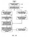
- the robotic instrument driver 400is first mounted (step 1000) with the drape 130 as illustrated, for example, in FIG. 11 .
- the guide and sheath instrument splayers 14, 16are loaded onto the robotic instrument driver 400 and initialized as illustrated in step 1100.
- the working instrument 30is loaded onto the robotic instrument system 2 and coupled to the ditherer 50 prior to inserting and/or advancing (step 1400) the guide instrument 4 and sheath instrument 6 into a body region (e.g., blood vessel) of the patient.
- a body regione.g., blood vessel
- the guide instrument 4 and sheath instrument 6may first be inserted into the body region of interest so as to place the distal tip of the guide instrument 4 near or adjacent to the region or site of interest.
- the working instrument 30may then be back loaded through the seal 40 an into the guide instrument 4 until the distal end 34 projects at least partially from the distal end of the guide instrument 4.
- a flushing fluidlike pressurized saline may be pumped or forced in between the working instrument 30 and guide instrument 4 to reduce friction and prevent retrograde flow through the device. Similar flushing fluids may be delivered between the guide instrument 4 and the sheath instrument 6.
- the physician or usermay enable this functionality by, for example, pressing a button 103a ( FIG. 4 ) or by using the graphical user interface (GUI) located at the operator control station 82.
- the graphical user interface (GUI)may include a touch screen 100 or another input device such as mouse, keyboard, pencil, pointer, or the like. Initiation of the force sensing feature causes, for example, the mechanical ditherer 50 to move back and forth and described herein.
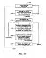
- an initialization sequenceis performed to establish a baseline. The process is represented as step 1600 in FIGS. 35 and 36 .
- the systemmay prompt the physician or user to verify (e.g., step 2000 in FIG. 36 ) that the distal end 34 of the working instrument 30 is not contacting any objects (e.g., tissue, other instruments, etc.). For example, a message may be displayed on the display 90 associated with the operator control station 82.
- the guide instrument 4/sheath instrument 6 and working instrument 30undergo the baseline process at an articulation position that closely approximates the articulation that will be used during the diagnostic or therapeutic procedure.
- the guide instrument 4 with the working instrument 30may be articulated into position in which the distal end of the working instrument 30 may contact a surface.
- the guide instrument 4 and or sheath instrument 6subsequently may be retracted proximally to ensure that the distal end 34 of the working instrument 30 is free of tissue or other objects.
- ECG or other diagnostic modalitiesmay be used to confirm that the distal end 34 of the working instrument 30 is indeed free of any contact with tissue.
- the physicianmay then baseline the system by, for example, pressing a button 103b ( FIG. 4 ) or by using the graphical user interface (GUI) located at the operator control station 82.
- the baselineis then taken and stored as illustrated in step 2100 of FIG. 36 for use in subsequent processing according to the algorithms described in detail herein.
- an unacceptable baseline measurementfor example, if the system detects forces indicative of touching with a surface or object, the physician may be prompted with a warning that requests confirmation of the current baseline. For instance, a warning such as "There are indications that you are touching tissue. Are you sure you want to proceed?" may be displayed to the physician on the display 90. The physician may then re-baseline the system or, alternatively, accept the current baseline.
- the guide instrument 4 and/or sheath 6 and working instrument 30may be manipulated by the physician (step 1700 in FIG. 35 ) and the estimated force experienced at the distal end 34 of the working instrument 30 is preferably displayed (step 1800 in FIG. 35 ) to the physician.
- a visual cue 404 or pointer 410 of the estimated errormay also be displayed as described herein with respect to FIGS. 34A-34D .
- the proceduremay include mapping heart tissue using a mapping catheter as a working instrument 30.
- the proceduremay include the ablation of tissue using an ablation catheter as a working instrument 30. While these two specific examples of procedures have been described herein it should be understood, that the system is not limited to the particular diagnostic or therapeutic procedure performed by the working instrument 30.
- the computer(s) 118 or other processors operatively coupled to the robotic instrument system 2may track the position and/or orientation of the guide instrument 4, sheath instrument 6, and working instrument 30 so that the physician may be prompted to re-baseline if the articulation meets or exceeds a pre-determined threshold value that has been established for movement of the guide 4 instrument and/or sheath instrument 6.
- the articulation of the guide instrument 4, sheath instrument 6, and working instrument 30may be visualized by the physician on a display 90.
- the underlying articulation datamay optionally be displayed as well.
- the systemwill prompt or suggest (step 2300) the physician to re-baseline the system. For example, a message may be displayed on the display 90 or an audible tone or alarm may sound when the error becomes too large.
- the systemmay automatically retract the guide instrument 4, sheath instrument 6, and working instrument 30 when the upper error limit is reached or surpassed. This procedure would forcibly require the physician to re-baseline.
- the prompt or suggestion made to the physicianmay be advisory and the physician may choose to ignore or disregard the suggestion made by the system and continue with the manipulation of the working instrument 30, guide instrument 4 and/or sheath 6 instrument.
Landscapes
- Health & Medical Sciences (AREA)
- Life Sciences & Earth Sciences (AREA)
- Animal Behavior & Ethology (AREA)
- Biophysics (AREA)
- Veterinary Medicine (AREA)
- Engineering & Computer Science (AREA)
- Biomedical Technology (AREA)
- Heart & Thoracic Surgery (AREA)
- Public Health (AREA)
- General Health & Medical Sciences (AREA)
- Surgery (AREA)
- Physics & Mathematics (AREA)
- Molecular Biology (AREA)
- Medical Informatics (AREA)
- Pathology (AREA)
- Pulmonology (AREA)
- Anesthesiology (AREA)
- Hematology (AREA)
- Manipulator (AREA)
- Surgical Instruments (AREA)
Description
- The invention relates generally to minimally-invasive instruments and systems, such as manually or robotically steerable catheter systems, and more particularly to steerable catheter systems for performing minimally invasive diagnostic and therapeutic procedures. More particularly, the invention pertains to systems and apparatus that are capable of measuring or sensing forces experienced by a medical instrument when in contact with surrounding objects such as tissue structures.
- Currently known minimally invasive procedures for the treatment of cardiac and other disease conditions use manually or robotically actuated instruments which may be inserted transcutaneously into body spaces such as the thorax or peritoneum, transcutaneously or percutaneously into lumens such as the blood vessels, through natural orifices and/or lumens such as the mouth and/or upper gastrointestinal tract, etc. For example, many conventional minimally-invasive cardiac diagnostic and/or interventional techniques involve accessing the right atrium of the heart percutaneously with a catheter or catheter system by way of the inferior vena cava. When controlling an elongate instrument, such as a catheter, in any one of these applications, the physician operator can push on the proximal end of the catheter and attempt to feel the distal end make contact with pertinent tissue structures, such as the walls of the heart. Some experienced physicians attempt to determine or gauge the approximate force being applied to the distal end of a catheter due to contact with tissue structures or other objects, such as other instruments, prostheses, or the like, by interpreting the loads they tactically sense at the proximal end of the inserted catheter with their fingers and/or hands. Such an estimation of the force, however, is quite challenging and somewhat imprecise given the generally compliant nature of many minimally-invasive instruments, associated frictional loads, dynamic positioning of the instrument versus nearby tissue structures, and other factors.
- Manually and robotically-navigated interventional systems and devices, such as steerable catheters, are well suited for performing a variety of minimally invasive procedures. Manually-navigated catheters generally have one or more handles extending from their proximal end with which the operator may steer the pertinent instrument. Robotically-navigated catheters may have a proximal interface configured to interface with a catheter driver comprising, for example, one or more motors configured to induce navigation of the elongate portion of the instrument in response to computer-based automation commands, commands input by the operator at a master input device, combinations thereof, or the like. Patent
US 6,565,554 describes a method of compensating friction forces in robotic surgical systems. The respective robotic surgical system features an instrument coupled to a robotic arm. At the end of the instrument end effectors are installed whereby the end effectors can be controlled by a master control device controlled by a surgeon. In particular inherent friction forces of the master controls are alleviated. PatentUS 6,102,850 discloses surgical instruments which are coupled to robotic arms. These instruments also have end effectors which can be controlled by master handles, in particular with an adjustable scale factor, so that the surgeon can control the resolution of the end effector movement. Regardless of the manual or electromechanical nature of the driving mechanism for a diagnostic or interventional instrument, the operator performing the procedure would prefer to have accurate, timely information regarding the forces experienced at the distal portion of the working instrument. There thus is a need for an improved force-sensing technology to facilitate the execution of minimally-invasive interventional procedures. It is desirable to have the capability to accurately monitor the loads applied by or to the subject medical instrument or device from adjacent tissues and other objects. - In one embodiment of the invention, an apparatus for positioning a distal end of a working instrument in a body lumen or site includes a guide instrument comprising an elongate member having a proximal region and a distal end and a lumen extending there through. A working instrument is disposed within the lumen of the guide instrument. The apparatus includes a reciprocating ditherer mechanically coupled to the working instrument and proximal region of the guide instrument and configured for moving the working instrument relative to the guide instrument. The apparatus includes at least one load cell coupled to the working instrument and containing a force sensor configured for measuring the forces experienced at a distal end of the working instrument. The apparatus includes a computer or processor that is configured to calculate an estimated force at the distal end of the working instrument based at least in part on the comparison of an output of the at least one load cell force sensor during zero or no load conditions (i.e., baseline conditions) and an output of the force sensor during load conditions (force applied to the distal end of the working instrument).
- In another embodiment, the robotic catheter system includes a robotically-operated guide instrument that includes a proximal region or end and a distal end with a lumen extending there through. The system includes a working instrument disposed within the lumen. The system further includes an oscillating ditherer operatively connected to the working instrument and the proximal region of the guide instrument for moving one or both of the working instrument and the guide catheter relative to each other. The system includes at least one force sensor configured for measuring a force applied to the working instrument by the oscillating ditherer.
FIG. 1A schematically illustrates a system for measuring forces on a distal end of a working instrument that is manipulated by a robotic instrument system.FIG. 1B illustrates a ditherer coupled to a manually operated, steerable guide catheter and a working instrument.FIG. 1C illustrates a ditherer coupled to a rigid member such as a trocar and a working instrument.FIG. 1D illustrates a robotically manipulated rigid or semi-rigid tool that includes a ditherer for reciprocating a working instrument therein for determining the force experienced at the distal end of the working instrument.FIG. 1E illustrates a ditherer that is used to move a working instrument back-and-forth within an outer flexible scope or elongate member.FIG. 1F illustrates a ditherer that is used to move a working instrument such as a guide wire that is disposed within an elongate imaging tool such as an endoscope.FIG. 2 illustrates a cross-sectional view of the guide instrument, sheath, and working instrument taken along the line A-A' ofFIG. 1A .FIG. 3 illustrates a physician or other using stationed at an operator control station that is operatively connected to a robotic instrument system according to one aspect of the invention.FIG. 4 illustrates a perspective view of an operator control station and associated cart.FIG. 5 illustrates a schematic representation of a system for dithering a working instrument relative to a guide instrument according to one embodiment of the invention.FIG. 6 illustrates a schematic representation of a system for dithering a working instrument relative to a guide instrument according to another embodiment of the invention.FIG. 7 illustrates a schematic representation of a system for dithering a working instrument relative to a guide instrument according to one embodiment of the invention.FIG. 8 illustrates a schematic representation of a system for dithering a working instrument relative to a guide instrument according to one embodiment of the invention.FIG. 9 illustrates a schematic representation of a system for dithering a working instrument relative to a guide instrument according to one embodiment of the invention.FIG. 10 illustrates a schematic representation of a system for dithering a working instrument relative to a guide instrument according to one embodiment of the invention.FIG. 11 illustrates a drape being positioned over the robotic instrument system.FIG. 12 illustrates a schematic representation of a system for dithering a working instrument relative to a guide instrument according to one embodiment of the invention. In this embodiment, the dithering motion is rotational as opposed to longitudinal.FIG. 13 illustrates a perspective view of a robotic instrument system without the working instrument.FIG. 14 illustrates a perspective view of a distal end of the robotic instrument system without the working instrument being attached. Also removed are the guide instrument and the outer sheath.FIG. 15 illustrates a working instrument being secured via two clamps to a seal. The seal interfaces with a flexible bellows that interfaces with the guide splayer. Also illustrated is a source of fluid (e.g., pressurized saline) that is used to flush the region between the guide instrument and the working instrument.FIG. 16 illustrates a perspective view of a robotic instrument system with the working instrument being loaded thereon.FIG. 17 illustrates another perspective view of a robotic instrument system with the working instrument being loaded thereon.FIG. 18A illustrates a guard ring that is mounted around a load bearing member of the ditherer.FIG. 18B illustrates the load bearing member being mounted on a pivot point between opposing load cells each of which contain a force sensor for measuring compressive forces.FIG. 18C illustrates the structure ofFIG. 18 with the guard ring mounted about the load bearing member.FIG. 19 illustrates a perspective view of the dither carriage holding the opposing load cells. Also shown are the opposing force sensors disposed on the load cells.FIG. 20 is a schematic representation of a working instrument being operatively coupled to the load bearing member of the ditherer. Also shown are the force sensors contained in the opposing load cells.FIGS. 21A-21B illustrate the waveform or force profile obtained from the force sensors during a single insertion and withdrawal cycle.FIG. 22 illustrates a baseline waveform or force profile that is overlaid with the waveform or force profile obtained when the distal end of the working instrument is subject to an external force. The dashed line represents the baseline (no force at distal end) while the solid line represents the measurements obtained in response to an applied force at the distal end of the working instrument.FIG. 23 illustrates a perspective view of a chassis for the robotic instrument system that holds the pivoting lever arm that moves the dither carriage back-and-forth in response to the cable-driven pulleys (cable not shown).FIG. 24 illustrates an exploded view of the ditherer carriage and the lever arm components that is used to dither the dither carriage back-and-forth according to one aspect of the invention.FIG. 25 illustrates a cable with crimp balls that is used to drive the ditherer according to one embodiment.FIG. 26 illustrates a top-down plan view of the lever arm and mechanical ditherer mounted on the dither carriage. The lever arm is shown at or near the "six o-clock" position in which the mechanical ditherer is at the end of withdrawal or the beginning of insertion into the guide instrument.FIG. 27 illustrates a top-down plan view of the lever arm and mechanical ditherer mounted on the dither carriage. The lever arm is shown at or near the "twelve o-clock" position in which the mechanical ditherer is at the end of insertion or the beginning of withdrawal into the guide instrument.FIG. 28 is a perspective view of the motor-based drive system that uses a plurality of pulleys to pivot the lever arm back-and-forth to cause reciprocating motion in the ditherer.FIG. 29 is another perspective view of the drive system illustrated inFIG. 28 .FIG. 30A illustrates a Touhy seal having a working instrument disposed therein.FIG. 30B illustrates another view of a Touhy seal.FIG. 30C illustrates a perspective view of a pivoting holder used as part of a mechanical ditherer according to one embodiment.FIG. 30D illustrates the Touhy being inserted into the pivoting holder ofFIG. 30C .FIG. 30E illustrates a perspective view of a cam having a groove therein.FIG. 30F illustrates the cam ofFIG. 30E engaged with the pivoting holder ofFIG. 30C .FIG. 30G illustrates a dither support block that holds the cam and pivoting holder. Also shown is a working instrument passing through the Touhy seal.FIG. 31 illustrates a top down plan view of the guide splayer along with the mechanical ditherer embodiment illustrated inFIGS. 30A-30G . A drive cable is shown coupled to the cam. A flexible bellows is also illustrated that is connected to the Touhy seal.FIG. 32A is an enlarged, top down plan view of the mechanical ditherer illustrated inFIGS. 30A-30G andFIG. 31 . A strain gauge is shown on the pivoting holder.FIG. 32B is an enlarged, top down plan view of the mechanical ditherer illustrated inFIGS. 30A-30G andFIG. 31 . In this embodiment, two opposing force sensors are affixed to the supports on either side of the pivoting member.FIGS. 33A and 33B illustrate perspective views of a mechanical ditherer according to another embodiment.FIG. 33C illustrates a cam having a slot therein.FIG. 33D illustrates a linkage having pins on opposing ends.FIG. 33E illustrates the linkage ofFIG. 33D in mating arrangement with the cam ofFIG. 33C .FIG. 33F illustrates a pivot holder connected to the linkage ofFIG. 33E .FIG. 33G illustrates a base used to hold the components of the ditherer illustrated inFIGS. 33A and 33B .FIGS. 34A-34D illustrate various embodiments in which the estimated force and estimated error are presented to a physician via a monitor, display or the like.FIG. 35 illustrates a process flow diagram for operating a robotic instrument system.FIG. 36 illustrates a process flow diagram for operating a robotic instrument system.FIG. 1A illustrates a schematic, top-level view of arobotic instrument system 2 according to one embodiment.FIGS. 1B-1F illustrate various other embodiments of asystem 2 that may utilize amechanical ditherer 50 or other dithering mechanism or device as described herein. For example,FIG. 1B illustrates a manually-operated,steerable guide catheter 500 that is mounted via abase 24 containing aditherer 50. Theditherer 50 is coupled to a workinginstrument 30 that is dithered back-and-forth relative to theguide catheter 500. The workinginstrument 30 may include any number generally elongate members that are typically used during medical diagnostic or therapeutic procedures. For example, the workinginstrument 30 may include by way of illustration and not limitation, a catheter, guide wire, imaging element, laser fiber or bundle of fibers, tool, or other instrument.FIG. 1C illustrates aditherer 50 used in conjunction with a relatively rigid elongate member such as, for example, atrocar 600. Theditherer 50 is coupled to a workinginstrument 30 that is dithered in a reciprocating fashion through a lumen (not shown) contained in thetrocar 600. As in the prior embodiment, abase 24 is used to secure theditherer 50 relative to thetrocar 600.FIG. 1D illustrates still another embodiment in which theditherer 50 is coupled to a workinginstrument 30 that is passed through atool 700 which may include a rigid or semi-rigid shaft having one or more lumens therein adapted to receive a workinginstrument 30. Thetool 700 may be coupled to ahousing 702 that mechanically and electrically couples thetool 700 to a robotically-controlled manipulator. For example, thetool 70 may be coupled to a robotically controlled instrument driver such as, for instance, the DA VINCI surgical system sold by Intuitive Surgical, Inc. of Sunnyvale, California.FIG. 1E illustrates an embodiment in which a workinginstrument 30 such as an endoscope is coupled to theditherer 50. The workinginstrument 30 can thus be moved relative to an outer flexible member such as a segmented,flexible scope 800 of the type developed by NeoGuide Systems, Inc.FIG. 1F illustrates still another embodiment in which, for example, theditherer 50 is used in connection with visualization tool such as anendoscope 900. In this embodiment, theditherer 30 is coupled to a workinginstrument 30 such as a guide wire that is dithered back-and-forth with respect to theendoscope 900. Theendoscope 900 may be rigid, flexible, or semi-rigid.- Referring back to
FIG. 1A , the depictedrobotic instrument system 2, variations of which are described in further detail, for example, inU.S. Utility Patent Application Nos. 11/640,099 filed on December 14, 2006 11/637,951 filed on December 11, 2006 11/481,433 filed on July 3, 2006 steerable guide instrument 4 and anouter sheath instrument 6 which may also be robotically-steerable. For illustrative purposes, a system comprising both a flexiblerobotic guide instrument 4 and a flexiblerobotic sheath instrument 6, each of which may also be termed a variation of a steerable "catheter", as described in the aforementioned applications, is depicted, although variations comprising only a flexiblerobotic guide instrument 4 or only a flexiblerobotic sheath instrument 6, as accompanied by a flexible workinginstrument 30 as described below, may be desired. Further, the dithering-based force sensing technologies described herein may be utilized with non-steerable and/or non-flexible or semi-flexible instrument set configurations (for example, to sense forces at the distal end of a working instrument advanced through a straight or bent, rigid, flexible, or semi-flexible steerable or nonsteerable trocar, or other straight or bent, rigid, flexible, or semi-flexible, steerable or nonsteerable minimally invasive instrument defining a working lumen in which a working instrument may be moved in an oscillatory fashion - such as the robotic instruments available from manufacturers such as NeoGuide Systems, Inc., Stereotaxis Inc., and Intuitive Surgical, Inc.). Furthermore, the dithering-based force sensing technologies described herein may be utilized in other applications with non-slender, or non-minimally-invasive, instruments, so long as such instruments define a lumen through which a working instrument may be moved in an oscillatory fashion and detected, as described below. - In the depicted embodiment of
FIG. 1A , robotic steering actuation is provided to the sheath and guide instruments in the depicted embodiment by arobotic instrument driver 400. Both theguide instrument 4 andsheath instrument 6 definerespective lumens 8, 10, and in the depicted configuration, thesheath instrument 6 coaxially surrounds a portion of theguide instrument 4. The robotically-steerable guide instrument 4 andsheath instrument 6 comprise a number ofcontrol members 12, as shown in the cross-sectional view ofFIG. 2 , that may be used to steer theguide instrument 4 and/orsheath instrument 4 using actuations from therobotic instrument driver 400. - The
control members 12 may comprise wires or the like that are selectively tensioned via respective proximal instrument portions or "splayers" 14, 16 that are configured to be interfaced with therobotic instrument driver 400 to provide steering actuation to theguide instrument 4 andsheath instrument 6, along with insertion or retraction a long the longitudinal axis of the proximal lumen defined by theguide instrument 4 orsheath instrument 6 via motors within theinstrument driver 400 which are configured to insert and retract thesplayers instrument driver 400 and/or relative to the operating table. For example, theguide splayer 14 andsheath splayer 16 may comprise a plurality of motor-driven, rotating spools or drums (not shown) that can selectively tension or release thecontrol members 12 of the pertinent instrument to provide controlled steering to theguide instrument 4 and/orsheath instrument 6. As described above, thesplayers robotic instrument driver 400 main structure as illustrated with arrows "A" inFIG. 1A . - As seen in the embodiment depicted in
FIG. 1A , theguide instrument 4 passes through thelumen 10 of thesheath instrument 6 and is thus moveable with respect thereto. As seen in the top detail ofFIG. 1A , thedistal end 18 of theguide instrument 4 projects distally with respect to thedistal end 20 of thesheath instrument 6. Of course, in other aspects, theguide instrument 4 may be withdrawn proximally such that thedistal end 18 is substantially flush with thedistal end 20 of thesheath instrument 6, or withdrawn proximally even further such that thedistal end 18 is hidden within thedistal end 20 of the sheath instrument. The contact surfaces between theguide instrument 4 and theouter sheath instrument 6 may be coated with a lubricous coating such as, for example, PTFE to reduced frictional forces there between. - Moreover, as explained in more detail below, an optional flushing fluid may be pumped or forcibly moved between the
guide instrument 4 andouter sheath instrument 6. The flushing fluid may act as a lubricant in addition to preventing retrograde flow of blood and other biological material into the space between theguide instrument 4 andouter sheath instrument 6. - Still referring to
FIG. 1A , a workinginstrument 30 is shown being secured to therobotic instrument driver 400. The workinginstrument 30 may comprise any number of types of instruments, including but not limited to guidewires, probes, laser fibers, injection devices, surgical tools, and catheters, such as electrophysiology catheters, ablation catheters, and the like.FIG. 1A illustrates an ablation catheter as the workinginstrument 30 withelectrodes 32 positioned at adistal end 34 of the ablation catheter. The workinginstrument 30, or "working catheter" in this instance, may be custom designed for use with therobotic instrument system 2 or, alternatively, the workinginstrument 30 or working catheter may comprise an off-the-shelf catheter such as those used by physicians in conventional, manually-navigated procedures. The workinginstrument 30 is loaded into therobotic instrument system 2 by passing thedistal end 34 through aseal 40. Theseal 40 may comprise a "Touhy" that has a small hole or opening through which the workinginstrument 30 passes. TheTouhy seal 40 may have an elongate or rigid body with a proximal end cap 44 (seen e.g., inFIGS. 13 ,14 ,16 , and17 ) or the like that is used to create a non-slip, fluid-tight seal between the Touhy 40 and the workinginstrument 30. - As seen in
FIG. 1A , theTouhy seal 40 is secured to a mechanical "ditherer" 50 via aclamp 54. Themechanical ditherer 50 is a mechanical subsystem that moves in a reciprocating or oscillating motion in the direction of arrow B, and may be coupled to other structures, such as a working instrument, to induce oscillatory, reciprocating, or "dithering" motion in such other structures. Themechanical ditherer 50 is driven by a motor (not shown inFIG. 1 A) which may be located on-board therobotic instrument driver 400 or, in other embodiments, off-board therobotic instrument driver 400 as a separate dithering actuation subsystem. In the depicted variation, themechanical ditherer 50 dithers or causes reciprocating axial movement of the workinginstrument 30 relative to theguide instrument 4 andsheath instrument 6. For example,FIG. 1A illustrates thedistal end 34 of the workinginstrument 30 dithering back and forth in the direction of arrow "C". The length or stroke of the dithering may be adjusted depending on the nature of the procedure but generally is less than a few millimeters. In some embodiments, the stroke of the dithering may be less than about 1.5 mm. - The
mechanical ditherer 50 comprises at least one force sensor (not shown inFIG. 1A ) that is used to detect the force or load that is being applied to the proximal portion of the workinginstrument 30. The force sensors are able to determine the insertion and withdrawal forces applied to the workinginstrument 30 via themechanical ditherer 50. Over one or more dithering cycles, these force profiles or waveforms can be used to accurately estimate contact forces at thedistal end 34 of the workinginstrument 30. For example,FIG. 1A shows thedistal end 34 in close proximity to ananatomical surface 70 which may comprise, for instance, cardiac tissue. Of course, contact forces may also come from other objects in the vicinity of thedistal end 34 such as, for instance, medical instruments or the like. - Still referring to
FIG. 1A , a flexible bellows 60 connects the distal end of theTouhy seal 40 to the proximal end of theguide instrument 4. In this regard, the flexible bellows 60 compresses and expands as the workinginstrument 30 is dithered with respect to theguide instrument 4 andsheath instrument 6. The flexible bellows 60 may be connected to afluid line 64 that is connected to a source of pressurized saline or the like. During use of therobotic instrument system 2, the pressurized saline is pumped into the space between the exterior of the workinginstrument 30 and the interior of theguide instrument 4 to prevent backflow of blood or other bodily fluids which, if allowed to retrograde into the guide instrument, could disrupt the ability to dither the workinginstrument 30 inside theguide instrument 4.Additional fluid lines guide instrument splayer 14 andsheath instrument splayer 16 to provide lubrication betweenguide instrument 4 andsheath instrument 6. - While
FIG. 1A illustrates themechanical ditherer 50 being coupled to theTouhy seal 40 it should be understood that themechanical ditherer 50 also may be coupled directly to a proximal region of the workinginstrument 30.FIG. 1A also illustrates asecond clamp 58 that is used to secure thehandle 36 of the workinginstrument 30 to therobotic instrument driver 400. In this regard, inadvertent movement of thehandle 36 does not affect the force sensing capabilities of themechanical ditherer 50. Thehandle 36 is isolated or grounded from the load sensing aspect of themechanical ditherer 50 which is discussed in more detail below. - By "dithering" the working
instrument 30 with respect to theguide instrument 4, the repeated cyclic motion may be utilized to overcome frictional challenges normally complicating the measurement, from a proximal location, of loads at thedistal end 34 of the workinginstrument 30 when in contact with a surface. In one embodiment, the dithering motion may be applied on a proximal region of the workinginstrument 30 as is illustrated inFIG. 1A and near the location at which relative axial load is measured. In other words, for example, if a user were to position a workinginstrument 30 down a lumen 8 of aguide instrument 4 so that thedistal end 34 of the workinginstrument 30 is sticking out slightly beyond thedistal end 18 of theguide instrument 4, and have both theguide instrument 4 and workinginstrument 30 threaded through the blood vessel(s) from a femoral location to the chambers of the heart, it may be difficult to sense contact(s) and force(s) applied to thedistal end 34 of the workinginstrument 30 due to the complications of the physical relationship with the associatedguide instrument 4. In particular, in a steady state wherein there is little or no relative axial or rotational motion between the workinginstrument 30 and guideinstrument 4, the static coefficient of friction is applicable, and there are relatively large frictional forces keeping the workinginstrument 30 in place adjacent to the guide instrument 4 (no relative movement between the two). - To release this relatively tight coupling and facilitate proximal measurement of forces applied to the
distal end 34 of the workinginstrument 30, dithering motion may be used to effectively break loose this frictional coupling. In one embodiment, such as the one illustrated inFIG. 1A , the dithering motion may be applied on a proximal region of the workinginstrument 30. In still other embodiments (not shown), it may be possible to dither theguide instrument 4 with respect to a stationary or substantially stationary workinginstrument 30. In yet another embodiment, both theguide instrument 4 and workinginstrument 30 may be dithered with respect to one another. - It should also be understood that
FIG. 1A illustrates longitudinal dithering of the workinginstrument 30 with respect to theguide instrument 4. It is possible in alternative embodiments to dither the workinginstrument 30 radially with respect to theguide instrument 4. Alternatively, theguide instrument 4 could be dithered radially with respect to the workinginstrument 30. In yet another alternative, theguide instrument 4 and workinginstrument 30 could both be dithered in the radial direction at the same time. - The dithering embodiment illustrated in
FIG. 1A avoids some of the complexities associated with using custom-made working instruments having embedded, distally-located sensors and instead facilitates the use of standard off-the-shelf working instruments 30. Thus, without altering the workinginstrument 30, by dithering the proximal region of the workinginstrument 30, either directly or via theseal 40, and placing the force sensors at the proximal region of the workinginstrument 30 it is possible to measure the estimated force that is applied at thedistal end 34 of the workinginstrument 30. By dithering the workinginstrument 30, the same is in motion substantially all of the time, and applied forces are shown in the force readings as incremental forces, thus substantially eliminating the effects of static friction after data processing has been executed, which is described in more detail below. - Still referring to
FIG. 1A , therobotic instrument system 2 may comprise an allstop button 74 that is used to terminate activity of therobotic instrument driver 400 when depressed. Thebutton 74 thus acts as a safety feature should one or more aspects of the device fail requiring manual user intervention. FIG. 1A also illustrates auser interface 80 that is operatively connected to therobotic instrument driver 400 and instrument set. The physician or other user interacts with theuser interface 80 to operate therobotic instrument driver 400 and associatedguide 4 and/orsheath 6 instruments, and associated workinginstrument 30. Theuser interface 80 may be connected to therobotic instrument driver 400 via a cable or the like. Alternatively, theuser interface 80 may be located in a geographically remote location and communication is accomplished, at least in part, over a wide area network such as the Internet. Of course theuser interface 80 may also be connected to therobotic instrument driver 400 via a local area network or even wireless network that is not located at a geographically remote location.FIG. 1A also illustrates adisplay 90 that is used to display various aspects of therobotic instrument system 2. For example, an image of theguide instrument 4,sheath instrument 6, and workinginstrument 30 may be displayed in real time on thedisplay 90 to provide the physician with the current orientation of the various devices as they are positioned, for example, within a body lumen or region of interest. As also shown inFIG. 1A , thedisplay 90 may include a readout on the estimated force experienced by thedistal end 34 of the workinginstrument 30. For example, the readout may include gradedscale 92 with amoveable arrow 94 that rises or falls as the force changes. Thedisplay 90 may also include a visual cue 96 indicating the amount of error associated with the estimated force. The visual cue 96 may include error bars as shown inFIG. 1A . Alternatively, the visual cue 96 may include a separate scale or graph that illustrates real time error in the measured force. The visual cue 96 may also include a color change to thearrow 94. In still another alternative, the visual cue or graphical element 96 may include a warning indicator or textual message.- In addition, the
display 90 may include a visual cue or signal that is present when the error exceeds a pre-determined threshold value (e.g., +/- 20% or +/- 20 grams). The estimated measured force at thedistal end 34 of the workinginstrument 30 may also be compared with a pre-determined threshold value. For example, if too much pressure is being applied to thedistal end 34, an audible warning signal may be initiated. Alternatively, a visual signal such as agraphical element 98 may be shown on thedisplay 90. In still another aspect, a haptic signal may be returned to the user, for example, a vibrational signal that can be felt by the user. FIG. 3 illustrates auser interface 80 located at anoperator control station 82 located remotely from an operating table 84 having a movable support-arm assembly 86. Thesupport assembly 86 is configured to movably support therobotic instrument driver 400 above the operating table 84 in order to position theguide instrument 4,sheath instrument 6, and working instrument 30 (not shown inFIG. 3 ). Acommunication link 86 transfers signals between theoperator control station 82 and therobotic instrument driver 400.- Referring now to
FIG. 4 , a view of another variation of anoperator control station 82 is depicted having threedisplays 90, a touchscreen user interface 100, and acontrol button console 102. Thecontrol button console 102 may comprise abutton 103a that is used to turn the force sensing capability on or off. In addition, thecontrol button console 102 may comprise adedicated button 103b that is used to baseline therobotic instrument driver 400 or associated instrument set. Of course, these functions may be implemented instead via the touchscreen user interface 100. Theoperator control station 82 comprisesmaster input device 104 that is manipulated by the physician to translate movement to therobotic instrument driver 400 and associated instruments. Also depicted inFIG. 4 is adevice disabling switch 106 configured to disable activity of the instrument temporarily. Thecart 108 depicted inFIG. 4 is configured for easy movability within the operating room or catheter lab, one advantage of which is location of theoperator control station 82 away from radiation sources, thereby decreasing radiation dosage to the operator. FIGS. 5-11 illustrate schematically various methods of accomplishing force estimation at thedistal end 34 of a workinginstrument 30 by using a dithering technique.FIG. 5 illustrates an embodiment in which the workinginstrument 30 dithers with respect to substantiallystationary guide instrument 4. In order to dither the workinginstrument 30 back and forth (longitudinally), themechanical ditherer 50 will drive the workinginstrument 30 through aforce sensor 110 which will measure the direct force needed to insert and withdraw the workinginstrument 30 in and out of theguide instrument 4. Theditherer 50 is mechanically grounded (via a mechanical linkage 52) to aproximal region 35 of theguide instrument 4 and is thus stationary to theguide instrument 4 but theforce sensor 110 and workinginstrument 30 move together relative to theguide instrument 4. Readings from theforce sensor 110 may be sent throughconditioning electronics 114 then to acomputer 118 for data processing, and finally to adisplay 122.FIG. 6 illustrates an alternative embodiment in which theditherer 50 andforce sensor 110 are mechanically linked to aseal 40 such as a Touhy seal. TheTouhy seal 40 acts as a fluidic seal which can add significant and erratic drag to the reciprocating in-and-out motion of the workinginstrument 30 which would adversely affect the accuracy of readings from theforce sensor 110. The embodiment ofFIG. 6 eliminates this effect by mechanically securing or locking theTouhy seal 40 to the workinginstrument 30 so the two are dithered together. In addition,FIG. 6 illustrates the flexible bellows 60 that is connected to the proximal end of theguide instrument 4 at one end and secured to theTouhy seal 40 at the other end. The bellows 60 includes aflush line 64 that is used to delivery pressured saline as described herein. The bellows 60 expands and contracts like an accordion with the dithering motion. The bellows 60 advantageously applies a very low drag force on the workinginstrument 30 during the dithering motion as opposed to the high drag force that would be applied if the workinginstrument 30 was dithered through theTouhy seal 40.FIG. 7 illustrates yet another embodiment which further secures or grounds ahandle 36 of the workinginstrument 30. Generally, disposable workinginstruments 30, such as the ablation catheters available from such suppliers as Boston Scientific and Biosense Webster under trade names such as "Blazer™" and "NaviStar™" are typically manufactured with ahandle 36 located on their proximal end. Unsecured, thishandle 36 would likely apply forces on theTouhy seal 40 and/or workinginstrument 30 that would be read by the force sensor(s) 110 and perhaps mistakenly be interpreted as applied forces at thedistal end 34 of the workinginstrument 30. Because of this, in the embodiment illustrated inFIG. 7 , thehandle 36 is isolated or guarded from theTouhy seal 40 and the force sensor(s) 110. The "guarding" may be accomplished by securing the instrument handle 36 into a holder such as theclamp 58 as shown inFIG. 1A .- The
handle 36 may be grounded in one of a number of ways. One variation is to physically ground thehandle 36 to theguide instrument 4 as shown inFIG. 7 . In this case thehandle 36 would be stationary relative to theguide instrument 4. As another alternative, thehandle 36 may be grounded to a common carriage or mounting plate on which the guide andsheath instrument splayers handle 36 is again grounded with respect to theguide instrument 4 albeit indirectly via a common carriage or mounting plate. FIG. 8 illustrates another embodiment in which thehandle 36 is secured to themechanical ditherer 50 via a securing member such as a clamp. In this embodiment, thehandle 36 would dither along with theTouhy seal 40 and the workinginstrument 30. It is important to note that the force used to dither thehandle 36 back and forth does not go through the force sensor(s) 110 and so any forces needed to move the handle 36 (or any accidental forces applied to the handle 36) are not seen by the force sensor(s) 110. Consequently, in this case, thehandle 36 would be completely guarded within the system and there would be no periodic offset force.- In one embodiment, a
drape 130 may be used to isolate non-sterile equipment from the sterile, surgical environment. In this regard, thedrape 130 may cover theditherer 50. If thedrape 130 is attached to the force sensor(s) 110 and happens to catch on a person or equipment, it may pull on the force sensor(s) 110 and add an unwanted force measurement (e.g., artifact). Because of this, the portion of thedrape 130 that is around the force sensor(s) 110 preferably is guarded - in this case by attaching it to arigid ring 132, comprising materials such as metals or polymers, that surrounds the force sensor(s) 110 andTouhy seal 40. Theguard ring 132 may be attached to the system with any number of methods. - As shown in
FIG. 9 , thering 132 is attached to a point where thedrape 130 dithers along with the workinginstrument 30. Thus, accidental pulls on the drape 130 (outside of the drape guard 132) generally are not transferred into the force sensor(s) 110 (but is transferred to the ditherer 50) and preferably does not result in a false force measurement. Another variation is illustrated inFIG. 10 in which thedrape guard ring 132 is secured to theguide instrument 4. Consequently, an accidental pull on the drape 130 (outside of the drape guard ring 132) advantageously is transferred into thestationary guide instrument 4 and not into the force sensor(s) 110. In this embodiment, there may be a small amount of movement between theTouhy seal 40 and/or force sensor(s) 110 (which is dithered) and thestationary guard ring 132, which will may cause bunching and stretching of thedrape 130 inside the guard ring. Thedrape 130 preferably is very compliant and this differential motion causes a small amplitude periodic force which is substantially the same during insertion and withdrawal and may thus be subtracted in subsequent force sensing data processing. FIG. 11 illustrates one embodiment of adrape 130 that is shown loaded onto arobotic instrument driver 400. Thedrape 130 includes platform covers 134 having a series of holes which are used to mount thesplayers platform cover 134 for theguide instrument splayer 14 is a flexible boot 136 made of a very flaccid rubber or polymeric material that is surrounded by aring 133 of semi-rigid material. Thering 133 is secured to therobotic instrument driver 400 such that any pulling, tugging, or other forces are transmitted through thedrape 130 to therobotic instrument driver 400 and not the flexible boot 136. For example thesemi-rigid ring 133 may be secured to the groundeddrape ring 132. In this regard, the boot 136 andring 133 isolate forces on thedrape 130 from affecting the force measurements obtained using theforce sensors 110. The workinginstrument 30 passes through the flexible boot 136 and can be secured to theditherer 50.- As mentioned above, a different variation of dithering comprises dithering the working
instrument 30 rotationally as opposed to longitudinally or axially. As seen inFIG. 12 , the force sensor(s) 110 would no longer be in series with themechanical ditherer 50. Rather, theditherer 50 would in this case be rotational and because it is an orthogonal motion (relative to the in-and-out motion due to the distal end force which may be applied to the working instrument 30), the orthogonal forces may be isolated from one another by using abearing 48 allowing theforce sensors 110 to measure the applied force at thedistal end 34 as isolated from the forces caused by the rotational dithering motion. - Regardless of whether the dithering motion is rotational or longitudinal, the structure of the flexible bellows 60 facilitates the operation of this dithering force measurement system. For example, in the longitudinal embodiment, the
bellows 60 provides low force from the longitudinal dithering and is volumetrically compliant to allow for the change of flush volume within thebellows 60 during the dithering process. In the rotational dithering embodiment, thebellows 60 is configured to allow for rotation of the ends of thebellows 60 while not creating a significant longitudinal force offset to the force sensor(s) 110. FIG. 13 illustrates a perspective view of arobotic instrument system 2 according to one embodiment of the invention. Therobotic instrument system 2 includes ahousing 150 that is partially exposed inFIG. 13 . Therobotic instrument system 2 generally comprises a carriage configured to interface with structures coupled to or comprising theguide instrument splayer 14, and a carriage configured to interface with structures coupled to or comprising thesheath instrument splayer 16.Longitudinal slots 154 defined by theouter housing 150 of therobotic instrument driver 400 are configured to facilitate longitudinal movement of the carriages and associatedsplayers outer housing 150 of therobotic instrument driver 400FIG. 14 illustrates a magnified perspective view of the distal portion of therobotic instrument system 2. Theguide instrument 4 andsheath instrument 6 are not shown for clarity purposes. As seen inFIG. 14 , theclamp 54 for theTouhy seal 40 may comprise arotatable handle 140 that is used to frictionally hold theTouhy seal 40 in place. For example, theclamp 54 may comprise alower seat 156 that is positioned on the load bearing aspect of theditherer 50 and anupper clamping member 158 that, when tightened via thehandle 140, frictionally secures theTouhy seal 40 in a sandwich arrangement. Thehandle 140 may comprise a groove or notch 142 that can be used to temporarily secure a flush line or the like.FIG. 14 also illustrates aclamp 58 for the handle 56 of the workinginstrument 30 that also comprises arotatable handle 144 that is used to frictionally secure thehandle 36 of the workinginstrument 30 in place. Theclamp 58 may comprise alower seat 160 that is fixedly secured to the carriage (or a support member secured to the carriage) and anupper clamping member 162 that, when tightened via thehandle 144, frictionally secures theproximal handle 36 in a sandwich arrangement. Therotatable handle 144 comprises a groove or notch 146 that can be used to temporarily secure a flush line or the like.FIG. 15 illustrates an assembly drawing of theguide instrument splayer 14 along with the mechanically coupledmechanical ditherer 50. A workinginstrument 30 is shown being inserted into the proximal end of theTouhy seal 40. Thedistal end 34 of the workinginstrument 30 is not shown inFIG. 15 . TheTouhy seal 40 ofFIG. 15 illustrates a proximal end having a series ofthreads 42 on which is mounted acap 44 which is illustrated in, for example,FIGS. 13 ,14 ,15 (showing threads 42), 16, and 17). Thecap 44 may be tightened on thethreads 42 to form a fluidic seal that prevents fluid from escaping between the interface of theseal 40 and the workinginstrument 30.FIG. 15 also illustrates aconduit 65 that is connected to the interior of theTouhy seal 40. Theconduit 65 is connected to a source of pressurizedflush solution 76 which may comprise, for instance, pressurized saline. Apressure regulator 78 or the like may be interposed in theconduit 65 between thepressurized flush solution 76 and theTouhy seal 40 to ensure that a constant pressure of fluid is applied. Of course, in other embodiments, theconduit 65 may be fluidically coupled to the flexible bellows 60.FIGS. 16 and17 illustrate perspective views of therobotic instrument system 2 having a workinginstrument 30 being inserted into theTouhy seal 40. The workinginstrument 30 passes through the lumen 8 of theguide instrument 4 and thelumen 10 of thesheath instrument 6. Thehandle 36 of the workinginstrument 30 is secured to therobotic instrument driver 400 via theclamp 58.FIGS. 16 and17 also illustrate a flush line orconduit 65 that is held in place via thegroove 146 in thehandle 144. With reference toFIGS. 16 and17 , the workinginstrument 30, which in certain embodiments may include an off-the-shelf steerable or nonsteerable catheter, may include a steeringmember 31 located on thehandle 36. In this case, the steeringmember 31 is preferably placed into a neutral position to permit steering by therobotic instrument driver 400.FIGS. 18A-C illustrate various aspects of themechanical ditherer 50 according to one embodiment.FIG. 18A illustrates a guard ring orcage 170 that is mounted to a moveable dither carriage 180 (as seen inFIGS. 18B and 18C ). Theguard ring 170 may be secured via mountingpads 172 having holes therein for passage of a screw, bolt, or the like (not shown) that mates withrespective holes 182 in thedither carriage 180. Theguard ring 170 may includeadditional holes 176 on a top surface thereof for mounting, for example, thedrape 130. In this regard, thedrape 130 dithers along with the workinginstrument 30. Any accidental pull on thedrape 130 would not be transferred into load cells and would not result in a false force measurement.FIG. 18B illustrates theload bearing member 190 of themechanical ditherer 50. Theload bearing member 190 is pivotally mounted to thedither carriage 180. Theload bearing member 190 pivots aboutpivot point 192 in the manner of an inverted pendulum. Thepivot point 192 may include ashaft 194, pin, bearing or the like that permits dithering movement of theload bearing member 190 along with thedither carriage 180. The dithering motion causes movement of thedither carriage 180 and attachedload bearing member 190 in the direction of arrow A inFIG. 18B . Two load cells 200 (one of which is illustrated inFIG. 18B ) are positioned on either side of theload bearing member 190 and each contain aforce sensor 204.FIG. 19 illustrates a perspective view of thedither carriage 180 including theload cells 200 having therespective force sensors 204 loaded therein. As best seen inFIGS. 18B and 18C , theload bearing member 190 is fixedly secured to thedither carriage 180 via thepivot point 192 and moves along therewith during the dithering movement.- The two
force sensors 204 measure compressive forces. In particular, the twoforce sensors 204 output a small voltage that is proportional to or correlates with the applied force. Theload bearing member 190 comprises theseat 156 onto which is mounted the Touhy seal 40 (or in other embodiments the working instrument 30). As thedither carriage 180 is moved back and forth in the reciprocating manner, the forces experienced on the proximal end of the working instrument 30 (or Touhy seal 40) are then measured via the output signals on the twoforce sensors 204. Theload bearing member 190, which swings back-and-forth in a pendulum-like manner, alternatively makes contact with the opposingforce sensors 204. When theload bearing member 190 does not contact aforce sensor 204, theforce sensor 204 outputs a baseline or zero signal (e.g., no voltage). - The analog voltage signal from each
force sensor 204 is amplified via an amplifier (not shown). The amplified signal may then pass through a flex circuit on therobotic instrument driver 400 structure to one or more circuit boards (not shown) mounted to the carriage or chassis. The analog signal then is transformed into a digital signal via an analog-to-digital converter (ADC). The digital signals can then be passed to an off-board computer located, for example, at theoperator control station 82. Theoperator control station 82 may then convert the digital data into a usable form using, for example, the single cycle subtraction algorithm described in more detail below. The separation of theload cells 200 is dimensioned such that there is a relatively small gap between theload cells 200 and theload bearing member 190 as there is a small dead band created when theload bearing member 190 is not touching either of the two opposingforce sensors 204. - Referring to
FIGS. 18B and 18C , thedither carriage 180 is secured to two c-shapedchannels 184. Thechannels 184 engage with correspondingly dimensioned rails (not shown) such that theentire dither carriage 180 is able to move back-and-forth in the direction of arrow A inFIG. 18B . FIG. 20 schematically illustrates theload bearing member 190 moving aboutpivot point 192 between the opposing load cells 202 holding theforce sensors 204. Thepivot point 192 may include astationary shaft 194 that is mounted with respect to the opposing load cells 202. For example, as seen inFIG. 19 , theshaft 194 may be driven through the base of both load cells 202. Theload bearing member 190 is sandwiched between the two load cells 202 and is held on theshaft 194 viabearings 196 or the like that allows rotational motion of theload bearing member 190 pivot about theshaft 194. Since thepivot 192 ultimately holds the workinginstrument 30, force felt by the workinginstrument 30 will cause theload bearing member 190 to rotate aboutpivot point 192 and press up against (e.g., compress) one of theforce sensors 204. Theforce sensors 204 measure this pivot force from which instrument force feedback can then be calculated.- The
mechanical ditherer 50 will dither theload cells 200 back and forth (in a linear displacement fashion approximately 1.5 mm from peak-to-peak). Of course other stroke lengths are also contemplated. As themechanical ditherer 50 changes direction, theload bearing member 190 rotates a very small amount to exchange force from one force sensor 206 to the other force sensor 206 then the linear motion of theditherer carriage 180 continues to carry theload bearing member 190 in a linear motion which pushes in or pulls out the workinginstrument 30. Theload bearing member 190 acts as a static lever arm. By using twoforce sensors 204, each can be used to verify that theother force sensor 204 is working properly. For example, the dead band zone where theload bearing member 190 is not touching eitherforce sensor 204 occurs once per dither cycle and is used to confirm theforce sensor 204 "zero load" position and to testproper force sensor 204 operation. - Extremely large forces will not be sensed by the
force sensors 204 but will be transferred directly to the load cell mounts 200 so as to protect theforce sensors 204 from damage. The load cell mounts 200 are designed to protect theforce sensors 204 from excessive forces from the load bearing member 190 (excessive forces applied to aforce sensors 204 may permanently damage them leading to incorrect force readings). To achieve this protection the load cell mounts 200 may have a precision ground cup into which theforce sensor 204 sits. The depth of this cup may be just slightly shorter than the height of theforce sensor 204 sitting in it, so that as theload bearing member 190 rotates to theforce sensor 204 and loadcell mount 200 it will push on theforce sensor 204 at first. As additional force is applied by theload bearing member 190, the force sensor 204 (which has a very slight amount of compliance) reduces in height until theload bearing member 190 strikes theload cell mount 200. Thus, by controlling the depth of the precision ground cup in theload cell mount 200 and by knowing the compliance of theforce sensor 204 in compression, the maximum force applied to theforce sensor 204 can be set, which will protect theforce sensor 204 excessive forces. Other methods of protecting theforce sensors 204 can be achieved by using shims or fine pitched screws to adjust for the point where forces to theforce 204 are shunted anyway. Theforce sensors 204 themselves may be uni-directional compression force sensors (sometimes referred to also as load cells) rated at 5 lbs (e.g., available from Honeywell Sensotec-Lebow of Ohio). FIGS. 21A and 21B illustrate an exemplary waveform of the measured or observed forces using theforce sensors 204 through a single dither cycle. The single dither cycle includes a single insertion stroke followed by a single withdrawal stroke. Positive forces are those measured during insertion while negative forces are those measured during withdrawal. In the embodiment described above, oneforce sensor 204 is used to measure insertion forces while the other, opposingforce sensor 204 is used to measure withdrawal forces. As seen inFIG. 21A , the applied force increases in a substantially linear manner until the force plateaus. The point at which the force begins to plateau is taken at that point when the workinginstrument 30 begins to dither axially with respect to theguide instrument 4. After a period of constant or substantially constant force, the force then begins to decrease in a substantially linear manner. The force then goes "negative" as the workinginstrument 30 is withdrawn from theguide instrument 4. The force then plateaus at a negative value before returning to the origin.FIG. 21A illustrates a condition in which no force is applied to thedistal end 34 of the workinginstrument 30.FIG. 21A illustrates two such waveforms (solid line 210 and dashed line 212). Both waveforms, while having different amplitudes, are substantially symmetrical. This feature is particularly advantageous because the forces are symmetrical in nature, the resulting waveform shows an equal force on insert and on withdrawal. Consequently, in processing the obtained force measurement data from theforce sensors 204, it is possible to take a one cycle average of the waveform that will eliminate the substantially symmetrical offset forces from the measurement leaving only the differential shift in force. This differential shift in force is the force that is applied at thedistal end 34 of the workinginstrument 30. Consequently, measured or observed forces at theproximal region 35 of the workinginstrument 30 may be used to accurately and consistently estimate forces applied to the workinginstrument 30 at thedistal end 34.FIG. 21B illustrates a first or "baseline" waveform 216 (solid line) taken when no force is applied to thedistal end 34 of the workinginstrument 30.FIG. 21 B also shows the waveform 218 (dashed line) taken when a force is applied to thedistal end 34 of the workinginstrument 30. As seen inFIG. 21B , the entire curve is shifted in the upward direction. With reference toFIG. 21B , the amplitude d1 is now larger than the amplitude d2. This difference between the baseline measurement and the measurement obtained upon application of a force may be used to quantify the force applied to thedistal end 34 of the workinginstrument 30.FIG. 22 illustrates a baseline waveform 216 (dashed line) along with an overlaid waveform 218 (solid line) obtained when a force is applied to thedistal end 34 of a workinginstrument 30. According to one embodiment, aportion 220 of the plateau region of both thebaseline waveform 216 and thewaveform 218 created from the contact force are sampled in regular increments. For example, the force readouts from thesensors 204 may be sampled at one millisecond increments over their entire cycle. While the entire waveform may be sampled, different embodiments may choose to ignore portions of the sampled waveform. For example, in one embodiment, only thoseportions 220 of the plateaus are kept or utilized for the force algorithm with the remaining readout figures being ignored or deleted. Theportion 220 of the waveform plateau may include a partial segment of the waveform that eliminates the endpoints as is shown inFIG. 22 .- With respect to the algorithm, baseline force measurements are obtained at the baseline sampling locations in the
plateau regions 220 for both the insertion stroke and the withdrawal stroke with no force applied ondistal end 34 of workinginstrument 30. An average force measurement is then obtained for each binned series of baseline data for both the insertion and withdrawal strokes. For generation of the baseline numbers, the average force measurements within theplateau regions 220 may be averaged over a number of cycles, for example, three cycles. As seen inFIG. 22 , sampled force measurements are also obtained over theplateau regions 220 with the workinginstrument 30 being subject to a force on thedistal end 34. Force measurements obtained over the binned insertion period are then averaged and subtracted from the average baseline force described above to produce an Update A value. The Update A value corresponds to the difference of the average forces obtained from the workinginstrument 30 under the insertion stroke with force applied and under insertion stroke with no force applied (i.e., baseline). Similarly, force measurements obtained over the binned withdrawal period are then averaged and subtracted from the average baseline withdrawal force described above to produce an Update B. - The estimated force on the
distal end 34 of the workinginstrument 30 may then be calculated by the following formula:
- Under this algorithm, Update A is determined at the completion of the insertion portion of the stroke while Update B is determined at the completion of the withdrawal portion of the stroke. For example, for a dithering rate of 2 Hz, the values (Update A or Update B) are updated about every ¼ second. Thus, as time progresses, Update A is updated, then Update B, then Update A, and so on and so forth. After each update step, the force value is re-calculated. It should be understood that a dither rate may be altered as needed. For example, in certain embodiments, the dither rate may vary between 0 Hz and about 10 Hz.
- While the algorithm described above uses a single cycle differential average of selected portions of the waveforms obtained during a contact state and a non-contact state there are other ways of obtaining similar information. For example, the averages may be calculated over more than one cycle. In addition, the estimated force may be obtained by comparing the profile or shape of the measured waveforms when the working instrument is in a contact state (e.g., experiencing a force) with the measured waveform obtained in a baseline state (e.g., no force). For instance, other embodiments might consider waveform slope, representative of mechanical stiffnesses in the system, as an indicator for which portion of the waveform contains useful data (i.e., signal) and which portion of the waveform is superfluous (i.e., noise).
FIG. 23 illustrates a perspective view of achassis 230 on which the guide splayer 14 (not shown) is mounted.FIG. 23 further illustrates thepivotable lever arm 232 that mechanically connected to thedither carriage 180. As best seen inFIGS. 23 and24 , thelever arm 232 includes ahole 234 for receiving abearing 236 that is mounted to a surface (e.g., top surface) of apulley 238. During the dithering operation, thelever arm 132 pivots aboutpivot point 240 which is the rotational axis of thebearing 236. Thelever arm 232 further includes aslot 242 that traverses a portion of the length of thelever arm 232. Theslot 242 is dimensioned to receive abearing 244 mounted in an eccentric manner on apulley 246. As best seen inFIG. 24 , thebearing 244 is mounted in an eccentric or offset manner by using acam 248 that is affixed to the upper surface of thepulley 246 by, for instance, screws 250. Thecam 248 may be "T-shaped" and include a pin orshaft 249 on which thebearing 244 is mounted.Different cams 248 having different distances between the center of rotation of thepulley 246 to thepin 249 may be used to alter the degree of eccentricity. This, in turn, would alter the stroke distance of themechanical ditherer 50.- Still referring to
FIGS. 23 and24 , thelever arm 232 includes another slottedportion 252 in a central region of thelever arm 232. The slottedportion 252 is generally oriented longitudinally along the length of thelever arm 232. The slottedportion 252 is dimensioned to receive abearing 254 this is rotationally mounted to thedither carriage 180. Thebearing 254 may be positioned on amount 256 that elevates a portion of thedither carriage 180. - As seen in
FIG. 23 , thedither carriage 180 is mounted to thechassis 230 using two crossed roller slides 258. The crossed roller slides 258 includes a base 260 that is fixedly secured to thechassis 230 and an innerslidable carriage 262 that is coupled to thedither carriage 180. A series of bearings or cylindrical steel rollers (not shown) enables thecarriage 262 to glide, almost friction-free, over thebase 260. For example, the cross roller slides 258 may be obtained from Del-Tron Inc., 5 Trowbridge Drive, Bethel, CT 06801 (model no. RD-1). - The
pulleys lever arm 232 include acircumferential groove 266 that is used to hold a drive cable 270 (shown inFIG. 25 ). Thedrive cable 270 may be formed from a bundle of numerous smaller wires formed from, for example, tungsten. As an example, thedrive cable 270 may have an 8 x 19 construction formed from 152 wires having a diameter of .008" that results in adrive cable 270 having an overall diameter of around .018." Thepulleys recesses 268 that formed in thegroove 266 and are used to mate with regular spacedcrimp balls 272 that located along the length of thedrive cable 270. The use of thecrimp balls 272 along with the mating recesses 268 ensures that there will be no slippage between thedrive cable 270 and thepulleys FIGS. 26 and27 illustrate top down plan views of thelever arm 232 andditherer 50 as thelever arm 232 is pivoted back and forth in the withdrawal and insertion strokes.FIG. 26 illustrates the eccentrically offsetbearing 244 in roughly a "six o'clock" position wherein thelever arm 232 is at or near the maximal displacement in the proximal direction. Thelever arm 232 inFIG. 26 is thus at the beginning of the insertion stroke or, alternatively, the end of the withdrawal stroke. In contrast,FIG. 27 illustrates the eccentrically offsetbearing 244 in roughly a "twelve o'clock" position wherein thelever arm 232 is at or near the maximal displacement in the distal direction. Thelever arm 232 inFIG. 27 is thus at the beginning of the withdrawal stroke or, alternatively, the end of the insertion stroke.- Referring now to
FIGS. 28 and29 , a motor drivenpulley system 280 is used to pivot thelever arm 232 back and forth which, in turn, causes the reciprocating motion of themechanical ditherer 50. As best seen inFIG. 29 , thedrive cable 270 is secured to amotor 282 having positioned thereon adrive pulley 284. Thedrive pulley 284 is secured to ashaft 283 of the motor using aclamp 287. Themotor 282 is secured to, for example, achassis 285 of therobotic instrument driver 400. Themotor 282 may be mounted so as to be stationary with respect to thechassis 230 holding thelever arm 232. Anencoder 281 is affixed to the backside of themotor 282 as seen inFIG. 29 and is used to accurately determine the position of theshaft 283 at any given point of time. - As seen in
FIGS. 28 and29 , thedrive cable 270 then passes through a series of proximally positioned pulleys 286. Thepulley system 280 may also include a tensioningpulley 288 that is used to provide a biasing force, for example, viasprings 290, to ensure that thedrive cable 270 remains taught. The tensioningpulley 288 may be used to provide tension to thedrive cable 270, for example, if theguide splayer 14 were moved longitudinally. As seen inFIG. 28 and29 , thecrimp balls 272 positioned along the length of thedrive cable 270 ensure proper registration between thecable 270 and the various pulleys. FIGS. 30A-30G , andFIGS. 31-33 illustrate another embodiment of a mechanical ditherer 300. In this embodiment, a rotationally driven cam 302 (best seen inFIGS. 30E and 30G ) is used to drive pivotingholder 304 that is secured to theguide instrument 30 and/orTouhy seal 40.FIGS. 30A and 30B illustrate aTouhy seal 40 that includes two tabs ordetents 306 that are used to mate with the pivotingholder 304.FIG. 30C illustrates the pivotingholder 304 which includes ahole 307 at one end thereof that is used as the pivot point during operation of the mechanical ditherer 300. The holder includes amain body section 308 that includes anaperture 309 for theTouhy seal 40 along withrecesses 310 for the tabs ordetents 306. Therecesses 310 serve to properly orient or register theTouhy seal 40 within the pivotingholder 304. The pivotingholder 304 further includes apin 312 or other projection that is used to mate with acorresponding groove 314 located in the rotationally drivencam 302, as is shown inFIGS. 30E and 30F . Thegroove 314 is spirally cut into the main, cylindrically-shaped body of thecam 302.Different cams 302 havinggrooves 314 with varying degrees of pitch may be used to adjust the stroke of the ditherer 300.FIG. 30G illustrates the pivotingholder 304 andcam 302 contained in adither support block 316. The pivotingholder 304 may be pinned to thedither support block 316 via thehole 307 so as to permit pivoting about the pivot point. Thecam 302 is mounted via a shaft, axle, or the like tosupports 318 on thedither support block 316.FIG. 30G further illustrates a portion of the workinginstrument 30 passing through theTouhy seal 40 that is positioned within the pivotingholder 304.FIG. 31 illustrates a top down view of the ditherer 300 being integrated into theguide instrument splayer 14. As seen inFIG. 31 , theTouhy seal 40 may be secured at a distal end to a flexible bellows 60. The other end of thebellows 60 may be coupled to theguide instrument 4. Also shown inFIG. 31 is adrive cable 320. Thedrive cable 320 is connected at a proximal end to a motor, servo or the like (not shown) to power the ditherer 300. The motor or servo may be located on-board therobotic instrument driver 400 or off-board. Thedrive cable 320 may include, for example, a bicycle cable that is rotationally driven back and forth. Rotational movement of thedrive cable 320 may be translated to thecam 302 which, in turn, causes the pivotingholder 304 to pivot back and forth. In one aspect, thegroove 314 is cut in such a manner (e.g., sinusoidal wave) that thecam 302 is rotated in a single direction to cause the back and forth movement of the pivotingholder 304. In this regard, thedrive cable 320 may be driven in a single direction. In another embodiment, the drivencable 320 may be driven in different directions to cause thecam 302 to rotate in different directions (e.g., clockwise then counter-clockwise).FIGS. 32A and32B illustrate a magnified view of the ditherer 300 and its components as it dithers in and out. The pivotingholder 304 pivots and follows thegroove 314 in thecam 302 via the mechanically linked pin 312 (obscured from view). In this embodiment, theTouhy 40 is thus moved back and forth along with the pivotingholder 304. Because the workinginstrument 30 is also securely fastened to theTouhy 40, the workinginstrument 30 also is dithered back and forth. In order to measure the insert and withdrawal forces, astrain gauge 322 may be mounted to the pivotingholder 304 to measure stresses therein so the force on thedistal end 34 of the workinginstrument 30 can be calculated, for example, in the manner described herein.FIG. 32B illustrates another embodiment for measuring force. In this embodiment,force sensors 204 are disposed on opposing sides of thesupports 318 of thedither support block 316. Theforce sensors 204 may include unidirectional force sensors as described herein. In the embodiment illustrated inFIG. 32B , there may be a dead band zone when the pivotingholder 304 is not contacting eitherforce sensor 204. The displacement of the pivotingholder 304 as well as the distances between theforce sensors 204 may be engineered to minimize this dead band zone.FIGS. 33A-33G illustrate another embodiment of amechanical ditherer 330. In this embodiment, adither assembly 336 includes an electric motor orservo 332 that is used to directly drive acam 334. Thedirect drive motor 332 is mounted to abase 350. Theelectric motor 332 directly engages with acam 334 that has a heart-shaped machinedslot 338 as illustrated inFIGS. 33C and 33E . Adrive linkage 340 interfaces with thecam 334 via a pin 342 (best seen inFIG. 33E ) that travels in thecam slot 338. The opposing end of thedrive linkage 340 contains apin 344 that engages with the pivotingholder 346 that is secured to theTouhy seal 40. In this embodiment, as theelectric motor 332 turns, the motor drives thecam 334, causing the pivotingholder 346 to pivot about its pin 348 (FIG. 33B ) and translate back and forth to effectuate the dithering motion.FIG. 33G illustrates a base 350 that is used to support the various components of thedither assembly 336. Force measurements may be obtained using either a strain gauge or one or more force sensors as described in the previous embodiment.FIGS. 34A - 34D illustrate various embodiments of how the estimated force at theproximal end 34 of the workinginstrument 30 is displayed to the physician or user. In one aspect, aforce scale 400 is displayed on, for instance, a display 90 (e.g.,FIGS. 3 and4 ) associated with theoperator control station 82. Theforce scale 400 may include a number of gradations positioned at regular intervals. For instance,FIG. 34A illustrates a force scale ranging from 0 grams to 100 grams of force with gradations every 25 grams. In one aspect, the user may control the scaling of theforce scale 400 via a button, switch, menu or the like at theoperator control station 82. As seen inFIG. 34A , the magnitude of the estimated force at thedistal end 34 of the workinginstrument 30 at any particular point in time is displayed via abar 402. Thebar 402 rises or falls as the force dynamically changes. Advantageously, thebar 402 is displayed in real-time or near real time as often as the algorithm described herein is updated. Still referring toFIG. 34A , avisual cue 404 indicative of the estimated error in the measured force is also displayed alongside the estimated force. InFIG. 34A , thevisual cue 404 may include an error bar that is displayed alongside itsown force scale 406 that indicates the amount of error associated with the particular measurement. As seen inFIG. 34A , theerror bar 404 combines total error with the baseline error on asingle force scale 406. Thevisual cue 404 may be updated in real-time or near real-time as the algorithm is updated. The system may be programmed such that if the baseline error goes above a pre-determined threshold value, the user is prompted to re-baseline the device.FIG. 34B illustrates an embodiment like that disclosed inFIG. 34A with the difference being that only total error is displayed on theerror bar 404 adjacent to theforce scale 406 associated with the errorvisual cue 404.FIG. 34C illustrates another embodiment in which the baseline error and total error are displayed as separate error bars 404a, 404b.FIG. 34D illustrates still another embodiment in which apointer 408 which, for example, is the form of an arrow or the like is used to display the estimated force. Thepointer 408 dynamically moves up and down as force is applied to thedistal end 34 of the workinginstrument 30. In one aspect, thepointer 408 may get larger as the force increases and, conversely, may get smaller as the force decreases. Also, thepointer 408 may change color as the force dynamically changes. For example, thepointer 408 may appear to have a "hot" color (e.g., red) if the estimated force is relatively high. In contrast, if there were little or no force experienced by the workinginstrument 30, the color may be a "cool" color (e.g., blue). An intermediate level of force may be shown using a medium color such as, for instance, yellow. In this regard, the physician is given an extra visual cue as to the forces experienced by the workinginstrument 30.FIG. 34D also illustrates apointer 410 that is used to display the estimated error in the force measurement. Like theforce measurement pointer 408, theerror pointer 410 dynamically moves as the error changes. Theerror pointer 410 may also change color in response to the degree of error. The estimated error may be displayed as a force (e.g., grams) or it may be displayed as a percentage or degree of deviation.- The estimated error that is displayed to the physician is based on a number of parameters that are empirically determined. For example, the estimated error may be based on the angle of the
sheath 6, articulation angle, rate of change of articulation angle, insertion distance, peak-to-peak forces, as well as the magnitude of the forces applied to thedistal end 34 of the workinginstrument 30. The estimated error may also be a function of the type or model of workinginstrument 30 that is used. This information may be gathered and input via theoperator control station 82. Information pertaining to the type of workinginstrument 30 as well as the empirical data may be stored in a memory or look up table that can then be compared with measured force values to output an estimated error. - Other methods for displaying force may include using a sound where the tone, pitch, or volume varies according to the measured force. Additionally, an audible warning may sound if a force reading (or a series of readings) reach a pre-determined, unsafe level. A warning light or graphical element 96 (e.g., as shown in
FIG. 1 ) or other type of alert such as a warning dialogue box can indicate when the force reaches unsafe levels. Haptic feedback can also indicate force increases so that as force readings increase, proportional force is felt on themaster controller 104 at theoperator control station 82. A vibrational warning may be sent through themaster controller 104 so that the physician feels a vibration when force levels have become unsafe. - With reference to
FIG. 35 , in a typical use of the device, therobotic instrument driver 400 is first mounted (step 1000) with thedrape 130 as illustrated, for example, inFIG. 11 . The guide andsheath instrument splayers robotic instrument driver 400 and initialized as illustrated instep 1100. In one aspect of the method, as illustrated instep 1200 ofFIG. 35 , the workinginstrument 30 is loaded onto therobotic instrument system 2 and coupled to theditherer 50 prior to inserting and/or advancing (step 1400) theguide instrument 4 andsheath instrument 6 into a body region (e.g., blood vessel) of the patient. Alternatively, as illustrated instep 1300 ofFIG. 35 , theguide instrument 4 andsheath instrument 6 may first be inserted into the body region of interest so as to place the distal tip of theguide instrument 4 near or adjacent to the region or site of interest. As seen instep 1500 inFIG. 35 , the workinginstrument 30 may then be back loaded through theseal 40 an into theguide instrument 4 until thedistal end 34 projects at least partially from the distal end of theguide instrument 4. A flushing fluid like pressurized saline may be pumped or forced in between the workinginstrument 30 and guideinstrument 4 to reduce friction and prevent retrograde flow through the device. Similar flushing fluids may be delivered between theguide instrument 4 and thesheath instrument 6. - To use to force sensing feature of the
robotic instrument system 2, the physician or user may enable this functionality by, for example, pressing abutton 103a (FIG. 4 ) or by using the graphical user interface (GUI) located at theoperator control station 82. The graphical user interface (GUI) may include atouch screen 100 or another input device such as mouse, keyboard, pencil, pointer, or the like. Initiation of the force sensing feature causes, for example, themechanical ditherer 50 to move back and forth and described herein. First, an initialization sequence is performed to establish a baseline. The process is represented asstep 1600 inFIGS. 35 and36 . The system may prompt the physician or user to verify (e.g.,step 2000 inFIG. 36 ) that thedistal end 34 of the workinginstrument 30 is not contacting any objects (e.g., tissue, other instruments, etc.). For example, a message may be displayed on thedisplay 90 associated with theoperator control station 82. - In one aspect of using the system described herein, the
guide instrument 4/sheath instrument 6 and workinginstrument 30 undergo the baseline process at an articulation position that closely approximates the articulation that will be used during the diagnostic or therapeutic procedure. For example, theguide instrument 4 with the workinginstrument 30 may be articulated into position in which the distal end of the workinginstrument 30 may contact a surface. Theguide instrument 4 and orsheath instrument 6 subsequently may be retracted proximally to ensure that thedistal end 34 of the workinginstrument 30 is free of tissue or other objects. Optionally, ECG or other diagnostic modalities may be used to confirm that thedistal end 34 of the workinginstrument 30 is indeed free of any contact with tissue. Once the physician is confident that thedistal end 34 is free from any contact with tissue or objects, the physician may then baseline the system by, for example, pressing abutton 103b (FIG. 4 ) or by using the graphical user interface (GUI) located at theoperator control station 82. The baseline is then taken and stored as illustrated instep 2100 ofFIG. 36 for use in subsequent processing according to the algorithms described in detail herein. - If an unacceptable baseline measurement is taken, for example, if the system detects forces indicative of touching with a surface or object, the physician may be prompted with a warning that requests confirmation of the current baseline. For instance, a warning such as "There are indications that you are touching tissue. Are you sure you want to proceed?" may be displayed to the physician on the
display 90. The physician may then re-baseline the system or, alternatively, accept the current baseline. Once an acceptable baseline has been accepted by the physician, theguide instrument 4 and/orsheath 6 and workinginstrument 30 may be manipulated by the physician (step 1700 inFIG. 35 ) and the estimated force experienced at thedistal end 34 of the workinginstrument 30 is preferably displayed (step 1800 inFIG. 35 ) to the physician. In addition, avisual cue 404 orpointer 410 of the estimated error may also be displayed as described herein with respect toFIGS. 34A-34D . - The physician continues with the operation as desired with real-time or near-real time display of the estimated contact forces experienced by the
distal end 34 of the workinginstrument 30. For example, the procedure may include mapping heart tissue using a mapping catheter as a workinginstrument 30. Alternatively, the procedure may include the ablation of tissue using an ablation catheter as a workinginstrument 30. While these two specific examples of procedures have been described herein it should be understood, that the system is not limited to the particular diagnostic or therapeutic procedure performed by the workinginstrument 30. - During the procedure, the computer(s) 118 or other processors operatively coupled to the
robotic instrument system 2 may track the position and/or orientation of theguide instrument 4,sheath instrument 6, and workinginstrument 30 so that the physician may be prompted to re-baseline if the articulation meets or exceeds a pre-determined threshold value that has been established for movement of theguide 4 instrument and/orsheath instrument 6. As explained with respect toFIG. 1A , the articulation of theguide instrument 4,sheath instrument 6, and workinginstrument 30 may be visualized by the physician on adisplay 90. The underlying articulation data may optionally be displayed as well. Likewise, as illustrated instep 2200 ofFIG. 36 , if the error associated with a particular force measurement is too large (e.g., above a pre-determined threshold value), the system will prompt or suggest (step 2300) the physician to re-baseline the system. For example, a message may be displayed on thedisplay 90 or an audible tone or alarm may sound when the error becomes too large. In one aspect, the system may automatically retract theguide instrument 4,sheath instrument 6, and workinginstrument 30 when the upper error limit is reached or surpassed. This procedure would forcibly require the physician to re-baseline. Of course, as illustrated inFIG. 36 , the prompt or suggestion made to the physician may be advisory and the physician may choose to ignore or disregard the suggestion made by the system and continue with the manipulation of the workinginstrument 30,guide instrument 4 and/orsheath 6 instrument.

Claims (14)
- An apparatus for positioning a distal end (34) of a working instrument (30) in a body lumen comprising:a guide instrument (4) comprising an elongate member having a proximal region (35) and a distal end (34) and a lumen (8) extending there through;a working instrument (30) disposed within the lumen (8);a reciprocating ditherer (50) mechanically coupled to the working instrument (30) and proximal region (35) of the guide instrument (4) and configured for moving the working instrument (30) relative to the guide instrument (4);at least one load cell (200) coupled to the working instrument (30) sand containing a force sensor (204) configured for measuring the forces experienced at the distal end (34) of the working instrument (30); anda processor (118) configured to calculate an estimated force at the distal end (34) of the working instrument (30) based at least in part on a comparison of an output of the at least one load cell (200) force sensor (204) during zero-load conditions and an output of the force sensor (204) during load conditions.
- The apparatus of claim 1, wherein the reciprocating motion is generally rotational.
- The apparatus of claim 1 or 2, wherein the working instrument (30) comprises an elongate, flexible medical instrument.
- The apparatus of any of claim 3, wherein the working instrument (30) is steerable.
- The apparatus of any of claims 1-4, wherein the working instrument (30) is robotically controlled.
- The apparatus of any of claims 1-5, further comprising a display (90) coupled to the processor (118), the processor configured for displaying the estimated force on the display.
- The apparatus of any of claims 1-6, wherein the reciprocating ditherer (50) is mechanically coupled to the working instrument (30) via a seal (40).
- The apparatus of claim 7, wherein the seal (40) is coupled to the guide instrument (4) via a flexible bellows (60).
- The apparatus of claim 7 or 8, wherein the seal (40) comprises a Touhy seal.
- The apparatus of any of claims 1-9, wherein the reciprocating ditherer (50) comprises a reciprocating carriage (180) containing a pivotable load bearing member (190).
- The apparatus of claim 10, wherein the carriage (180) is coupled to a reciprocating lever arm (232) operatively connected at one end thereof to a bearing (244) eccentrically mounted to a pulley (246).
- The apparatus of any of claims 1-11, the guide instrument (4) comprising a guide splayer (14).
- The apparatus of any of claims 1-12, wherein the at least one force sensor (204) comprises a compression force sensor.
- A robotic catheter system (2) including the apparatus of claim 1, wherein the at least one force sensor (204) is configured for measuring a force applied to the working instrument (30) by the oscillating ditherer (50), wherein the processor (118) is configured to calculate an estimated force experienced at the distal end (34) of the working instrument (30) based at least in part on a comparison of an output of the at least one force sensor (204) during zero-load conditions and an output of the at least one force sensor (204) during load conditions.
Applications Claiming Priority (3)
| Application Number | Priority Date | Filing Date | Title |
|---|---|---|---|
| US77606506P | 2006-02-22 | 2006-02-22 | |
| US80135506P | 2006-05-17 | 2006-05-17 | |
| PCT/US2007/062617WO2007098494A1 (en) | 2006-02-22 | 2007-02-22 | System and apparatus for measuring distal forces on a working instrument |
Publications (2)
| Publication Number | Publication Date |
|---|---|
| EP1986563A1 EP1986563A1 (en) | 2008-11-05 |
| EP1986563B1true EP1986563B1 (en) | 2012-12-26 |
Family
ID=38180663
Family Applications (1)
| Application Number | Title | Priority Date | Filing Date |
|---|---|---|---|
| EP07757358ANot-in-forceEP1986563B1 (en) | 2006-02-22 | 2007-02-22 | System and apparatus for measuring distal forces on a working instrument |
Country Status (5)
| Country | Link |
|---|---|
| US (4) | US8092397B2 (en) |
| EP (1) | EP1986563B1 (en) |
| JP (1) | JP5236502B2 (en) |
| CN (1) | CN101389285B (en) |
| WO (1) | WO2007098494A1 (en) |
Cited By (1)
| Publication number | Priority date | Publication date | Assignee | Title |
|---|---|---|---|---|
| RU2807937C1 (en)* | 2022-07-26 | 2023-11-21 | федеральное государственное бюджетное образовательное учреждение высшего образования "Московский государственный медико-стоматологический университет имени А.И. Евдокимова" Министерства здравоохранения Российской Федерации (ФГБОУ ВО МГМСУ им. А.И. Евдокимова Минздрава России) | Multifunctional wireless device with replaceable surgical instruments for measuring their orientation angles in space and forces and moments affecting them during neurosurgical operations |
Families Citing this family (266)
| Publication number | Priority date | Publication date | Assignee | Title |
|---|---|---|---|---|
| US8768516B2 (en)* | 2009-06-30 | 2014-07-01 | Intuitive Surgical Operations, Inc. | Control of medical robotic system manipulator about kinematic singularities |
| WO2005087128A1 (en) | 2004-03-05 | 2005-09-22 | Hansen Medical, Inc. | Robotic catheter system |
| US20060167529A1 (en) | 2005-01-26 | 2006-07-27 | Schecter Stuart O | Method and algorithm for defining the pathologic state from a plurality of intrinsically and extrinsically derived signals |
| US20090030332A1 (en)* | 2005-01-26 | 2009-01-29 | Schecter Stuart O | microfabricated cardiac sensor with tactile feedback and method and apparatus for calibrating the same using a plurality of signals |
| US20100312129A1 (en) | 2005-01-26 | 2010-12-09 | Schecter Stuart O | Cardiovascular haptic handle system |
| JP2009500086A (en) | 2005-07-01 | 2009-01-08 | ハンセン メディカル,インク. | Robotic guide catheter system |
| EP1907041B1 (en)* | 2005-07-11 | 2019-02-20 | Catheter Precision, Inc. | Remotely controlled catheter insertion system |
| US10357184B2 (en)* | 2012-06-21 | 2019-07-23 | Globus Medical, Inc. | Surgical tool systems and method |
| EP1986563B1 (en) | 2006-02-22 | 2012-12-26 | Hansen Medical, Inc. | System and apparatus for measuring distal forces on a working instrument |
| US8989528B2 (en)* | 2006-02-22 | 2015-03-24 | Hansen Medical, Inc. | Optical fiber grating sensors and methods of manufacture |
| US8406901B2 (en) | 2006-04-27 | 2013-03-26 | Medtronic, Inc. | Sutureless implantable medical device fixation |
| ATE472980T1 (en)* | 2006-05-17 | 2010-07-15 | Hansen Medical Inc | ROBOTIC INSTRUMENT SYSTEM |
| WO2007146984A2 (en) | 2006-06-13 | 2007-12-21 | Intuitive Surgical, Inc. | Control system configured to compensate for non-ideal actuator-to-joint linkage characteristics in a medical robotic system |
| US9492657B2 (en)* | 2006-11-30 | 2016-11-15 | Medtronic, Inc. | Method of implanting a medical device including a fixation element |
| US12290277B2 (en) | 2007-01-02 | 2025-05-06 | Aquabeam, Llc | Tissue resection with pressure sensing |
| US9232959B2 (en) | 2007-01-02 | 2016-01-12 | Aquabeam, Llc | Multi fluid tissue resection methods and devices |
| US7922693B2 (en)* | 2007-03-19 | 2011-04-12 | Hansen Medical, Inc. | Apparatus systems and methods for flushing gas from a catheter of a robotic catheter system |
| WO2008118481A2 (en) | 2007-03-26 | 2008-10-02 | Hansen Medical, Inc. | Robotic catheter systems and methods |
| US20080255413A1 (en)* | 2007-04-13 | 2008-10-16 | Michael Zemlok | Powered surgical instrument |
| WO2008131303A2 (en) | 2007-04-20 | 2008-10-30 | Hansen Medical, Inc. | Optical fiber shape sensing systems |
| WO2008133956A2 (en)* | 2007-04-23 | 2008-11-06 | Hansen Medical, Inc. | Robotic instrument control system |
| EP2148712B1 (en)* | 2007-04-27 | 2018-10-31 | Maquet Critical Care AB | Control unit and display unit for an emg controlled ventilator |
| US20130165945A9 (en)* | 2007-08-14 | 2013-06-27 | Hansen Medical, Inc. | Methods and devices for controlling a shapeable instrument |
| EP2626030A3 (en) | 2007-08-14 | 2017-03-08 | Koninklijke Philips N.V. | Robotic instrument systems and methods utilizing optical fiber sensors |
| US20090076476A1 (en)* | 2007-08-15 | 2009-03-19 | Hansen Medical, Inc. | Systems and methods employing force sensing for mapping intra-body tissue |
| US8357152B2 (en) | 2007-10-08 | 2013-01-22 | Biosense Webster (Israel), Ltd. | Catheter with pressure sensing |
| US8535308B2 (en) | 2007-10-08 | 2013-09-17 | Biosense Webster (Israel), Ltd. | High-sensitivity pressure-sensing probe |
| US8986246B2 (en) | 2008-01-16 | 2015-03-24 | Catheter Robotics Inc. | Remotely controlled catheter insertion system |
| US8740840B2 (en)* | 2008-01-16 | 2014-06-03 | Catheter Robotics Inc. | Remotely controlled catheter insertion system |
| US9211160B2 (en) | 2008-01-16 | 2015-12-15 | Luiz Geraldo Pivotto | Remotely controlled catheter insertion system with automatic control system |
| WO2009092059A2 (en)* | 2008-01-16 | 2009-07-23 | Catheter Robotics, Inc. | Remotely controlled catheter insertion system |
| US20090228020A1 (en)* | 2008-03-06 | 2009-09-10 | Hansen Medical, Inc. | In-situ graft fenestration |
| ES2769535T3 (en) | 2008-03-06 | 2020-06-26 | Aquabeam Llc | Tissue ablation and cauterization with optical energy carried in a fluid stream |
| US20090254083A1 (en)* | 2008-03-10 | 2009-10-08 | Hansen Medical, Inc. | Robotic ablation catheter |
| US8792964B2 (en)* | 2008-03-12 | 2014-07-29 | Siemens Aktiengesellschaft | Method and apparatus for conducting an interventional procedure involving heart valves using a robot-based X-ray device |
| WO2010036746A1 (en)* | 2008-09-24 | 2010-04-01 | St. Jude Medical | System and method of automatic detection of obstructions for a robotic catheter system |
| US8641664B2 (en)* | 2008-03-27 | 2014-02-04 | St. Jude Medical, Atrial Fibrillation Division, Inc. | Robotic catheter system with dynamic response |
| US9161817B2 (en)* | 2008-03-27 | 2015-10-20 | St. Jude Medical, Atrial Fibrillation Division, Inc. | Robotic catheter system |
| US8317744B2 (en) | 2008-03-27 | 2012-11-27 | St. Jude Medical, Atrial Fibrillation Division, Inc. | Robotic catheter manipulator assembly |
| US8343096B2 (en) | 2008-03-27 | 2013-01-01 | St. Jude Medical, Atrial Fibrillation Division, Inc. | Robotic catheter system |
| US20090248042A1 (en)* | 2008-03-27 | 2009-10-01 | Kirschenman Mark B | Model catheter input device |
| US9241768B2 (en) | 2008-03-27 | 2016-01-26 | St. Jude Medical, Atrial Fibrillation Division, Inc. | Intelligent input device controller for a robotic catheter system |
| US8684962B2 (en) | 2008-03-27 | 2014-04-01 | St. Jude Medical, Atrial Fibrillation Division, Inc. | Robotic catheter device cartridge |
| US8317745B2 (en) | 2008-03-27 | 2012-11-27 | St. Jude Medical, Atrial Fibrillation Division, Inc. | Robotic catheter rotatable device cartridge |
| US8641663B2 (en)* | 2008-03-27 | 2014-02-04 | St. Jude Medical, Atrial Fibrillation Division, Inc. | Robotic catheter system input device |
| US8437832B2 (en) | 2008-06-06 | 2013-05-07 | Biosense Webster, Inc. | Catheter with bendable tip |
| US8290571B2 (en)* | 2008-08-01 | 2012-10-16 | Koninklijke Philips Electronics N.V. | Auxiliary cavity localization |
| US9101734B2 (en)* | 2008-09-09 | 2015-08-11 | Biosense Webster, Inc. | Force-sensing catheter with bonded center strut |
| US8083691B2 (en) | 2008-11-12 | 2011-12-27 | Hansen Medical, Inc. | Apparatus and method for sensing force |
| US8317746B2 (en) | 2008-11-20 | 2012-11-27 | Hansen Medical, Inc. | Automated alignment |
| US20100331856A1 (en)* | 2008-12-12 | 2010-12-30 | Hansen Medical Inc. | Multiple flexible and steerable elongate instruments for minimally invasive operations |
| US8161838B2 (en) | 2008-12-22 | 2012-04-24 | Intuitive Surgical Operations, Inc. | Method and apparatus for reducing at least one friction force opposing an axial force exerted through an actuator element |
| US9326700B2 (en)* | 2008-12-23 | 2016-05-03 | Biosense Webster (Israel) Ltd. | Catheter display showing tip angle and pressure |
| US8600472B2 (en) | 2008-12-30 | 2013-12-03 | Biosense Webster (Israel), Ltd. | Dual-purpose lasso catheter with irrigation using circumferentially arranged ring bump electrodes |
| US8475450B2 (en)* | 2008-12-30 | 2013-07-02 | Biosense Webster, Inc. | Dual-purpose lasso catheter with irrigation |
| US20110238010A1 (en)* | 2008-12-31 | 2011-09-29 | Kirschenman Mark B | Robotic catheter system input device |
| JP5380122B2 (en)* | 2009-03-24 | 2014-01-08 | テルモ株式会社 | Medical device |
| WO2010114972A2 (en)* | 2009-04-01 | 2010-10-07 | University Of Florida Research Foundation, Inc. | Apparatuses for advancing an endoscope through a passage |
| US9254123B2 (en) | 2009-04-29 | 2016-02-09 | Hansen Medical, Inc. | Flexible and steerable elongate instruments with shape control and support elements |
| WO2010138499A1 (en)* | 2009-05-25 | 2010-12-02 | Stereotaxis, Inc. | Remote manipulator device |
| US10537713B2 (en)* | 2009-05-25 | 2020-01-21 | Stereotaxis, Inc. | Remote manipulator device |
| US8918212B2 (en) | 2009-06-24 | 2014-12-23 | Intuitive Surgical Operations, Inc. | Arm with a combined shape and force sensor |
| US8780339B2 (en) | 2009-07-15 | 2014-07-15 | Koninklijke Philips N.V. | Fiber shape sensing systems and methods |
| US20110015648A1 (en)* | 2009-07-16 | 2011-01-20 | Hansen Medical, Inc. | Endoscopic robotic catheter system |
| WO2011008922A2 (en) | 2009-07-16 | 2011-01-20 | Hansen Medical, Inc. | Endoscopic robotic catheter system |
| US20110015484A1 (en)* | 2009-07-16 | 2011-01-20 | Alvarez Jeffrey B | Endoscopic robotic catheter system |
| US9439736B2 (en) | 2009-07-22 | 2016-09-13 | St. Jude Medical, Atrial Fibrillation Division, Inc. | System and method for controlling a remote medical device guidance system in three-dimensions using gestures |
| US9330497B2 (en) | 2011-08-12 | 2016-05-03 | St. Jude Medical, Atrial Fibrillation Division, Inc. | User interface devices for electrophysiology lab diagnostic and therapeutic equipment |
| US20110184231A1 (en)* | 2009-07-28 | 2011-07-28 | Page Brett M | Deflectable instrument ports |
| KR100997194B1 (en)* | 2009-08-18 | 2010-11-30 | 주식회사 이턴 | Remote operation robot system for indirectly providing tactile sensation and control method thereof |
| DE102009050200B3 (en) | 2009-10-21 | 2011-03-31 | Böllhoff Verbindungstechnik GmbH | Process monitoring for high-speed joining |
| US10688278B2 (en) | 2009-11-30 | 2020-06-23 | Biosense Webster (Israel), Ltd. | Catheter with pressure measuring tip |
| US8920415B2 (en) | 2009-12-16 | 2014-12-30 | Biosense Webster (Israel) Ltd. | Catheter with helical electrode |
| US8521462B2 (en) | 2009-12-23 | 2013-08-27 | Biosense Webster (Israel), Ltd. | Calibration system for a pressure-sensitive catheter |
| US8529476B2 (en) | 2009-12-28 | 2013-09-10 | Biosense Webster (Israel), Ltd. | Catheter with strain gauge sensor |
| US8608735B2 (en) | 2009-12-30 | 2013-12-17 | Biosense Webster (Israel) Ltd. | Catheter with arcuate end section |
| JP5775881B2 (en)* | 2010-01-15 | 2015-09-09 | イマージョン コーポレーションImmersion Corporation | System and method for minimally invasive surgical tools with tactile feedback |
| US8374670B2 (en) | 2010-01-22 | 2013-02-12 | Biosense Webster, Inc. | Catheter having a force sensing distal tip |
| MX2012010278A (en)* | 2010-03-15 | 2012-09-28 | Int Truck Intellectual Prop Co | Hydraulic brake caliper piston insertion force gauge tool. |
| US9888973B2 (en) | 2010-03-31 | 2018-02-13 | St. Jude Medical, Atrial Fibrillation Division, Inc. | Intuitive user interface control for remote catheter navigation and 3D mapping and visualization systems |
| AU2011237339B2 (en) | 2010-04-08 | 2014-10-30 | BiO2 Medical, Inc. | Catheter hub |
| JP2013525847A (en)* | 2010-04-21 | 2013-06-20 | アプライド プレシジョン インコーポレイテッド | Uniform light source for imaging equipment |
| US20110295248A1 (en) | 2010-05-28 | 2011-12-01 | Hansen Medical, Inc. | System and method for automated minimally invasive instrument command |
| US8798952B2 (en)* | 2010-06-10 | 2014-08-05 | Biosense Webster (Israel) Ltd. | Weight-based calibration system for a pressure sensitive catheter |
| JP4940332B2 (en)* | 2010-06-15 | 2012-05-30 | 日本ライフライン株式会社 | catheter |
| US8672837B2 (en) | 2010-06-24 | 2014-03-18 | Hansen Medical, Inc. | Methods and devices for controlling a shapeable medical device |
| US8226580B2 (en) | 2010-06-30 | 2012-07-24 | Biosense Webster (Israel), Ltd. | Pressure sensing for a multi-arm catheter |
| US20120035596A1 (en)* | 2010-08-04 | 2012-02-09 | Tegg Troy T | Disposable Drive Interface for Longitudinal Movement of an Elongate Medical Device |
| US8380276B2 (en) | 2010-08-16 | 2013-02-19 | Biosense Webster, Inc. | Catheter with thin film pressure sensing distal tip |
| FR2964054B1 (en)* | 2010-08-31 | 2013-05-24 | Airbus Operations Sas | REMOTE PIVOTING METHOD AND TOOL FOR IMPLEMENTING THE SAME |
| US20120071752A1 (en) | 2010-09-17 | 2012-03-22 | Sewell Christopher M | User interface and method for operating a robotic medical system |
| US8731859B2 (en) | 2010-10-07 | 2014-05-20 | Biosense Webster (Israel) Ltd. | Calibration system for a force-sensing catheter |
| US8979772B2 (en)* | 2010-11-03 | 2015-03-17 | Biosense Webster (Israel), Ltd. | Zero-drift detection and correction in contact force measurements |
| US8532738B2 (en)* | 2010-11-04 | 2013-09-10 | Biosense Webster (Israel), Ltd. | Visualization of catheter-tissue contact by map distortion |
| CN102462536A (en)* | 2010-11-18 | 2012-05-23 | 无锡佑仁科技有限公司 | Duct propulsion operating device for vascular intervention surgical robot |
| US10112045B2 (en) | 2010-12-29 | 2018-10-30 | Medtronic, Inc. | Implantable medical device fixation |
| US9775982B2 (en) | 2010-12-29 | 2017-10-03 | Medtronic, Inc. | Implantable medical device fixation |
| US20120191079A1 (en) | 2011-01-20 | 2012-07-26 | Hansen Medical, Inc. | System and method for endoluminal and translumenal therapy |
| US9937002B2 (en) | 2011-03-08 | 2018-04-10 | Nexus Control Systems, Llc | Ablation catheter system with safety features |
| CA2842302C (en) | 2011-03-08 | 2019-09-10 | Todd J. Cohen | Ablation catheter system with safety features |
| US8942828B1 (en) | 2011-04-13 | 2015-01-27 | Stuart Schecter, LLC | Minimally invasive cardiovascular support system with true haptic coupling |
| US9220433B2 (en) | 2011-06-30 | 2015-12-29 | Biosense Webster (Israel), Ltd. | Catheter with variable arcuate distal section |
| US20130018306A1 (en)* | 2011-07-13 | 2013-01-17 | Doron Moshe Ludwin | System for indicating catheter deflection |
| US20130030363A1 (en) | 2011-07-29 | 2013-01-31 | Hansen Medical, Inc. | Systems and methods utilizing shape sensing fibers |
| US9662169B2 (en) | 2011-07-30 | 2017-05-30 | Biosense Webster (Israel) Ltd. | Catheter with flow balancing valve |
| US10779855B2 (en) | 2011-08-05 | 2020-09-22 | Route 92 Medical, Inc. | Methods and systems for treatment of acute ischemic stroke |
| US9750576B2 (en)* | 2011-09-20 | 2017-09-05 | Corindus, Inc. | Variable drive force apparatus and method for robotic catheter system |
| US10791950B2 (en) | 2011-09-30 | 2020-10-06 | Biosense Webster (Israel) Ltd. | In-vivo calibration of contact force-sensing catheters using auto zero zones |
| US20130194083A1 (en)* | 2011-10-18 | 2013-08-01 | Amrita Vishwa Vidyapeetham | System and method for delivering haptic force feedback with cable and moving capstan drive mechanism |
| KR101828453B1 (en)* | 2011-12-09 | 2018-02-13 | 삼성전자주식회사 | Medical robotic system and control method for thereof |
| US20130165946A1 (en)* | 2011-12-22 | 2013-06-27 | Kulbir S. Sandhu | Apparatus for a robotic control and guidance system |
| US8652031B2 (en) | 2011-12-29 | 2014-02-18 | St. Jude Medical, Atrial Fibrillation Division, Inc. | Remote guidance system for medical devices for use in environments having electromagnetic interference |
| US9687289B2 (en) | 2012-01-04 | 2017-06-27 | Biosense Webster (Israel) Ltd. | Contact assessment based on phase measurement |
| US9956042B2 (en) | 2012-01-13 | 2018-05-01 | Vanderbilt University | Systems and methods for robot-assisted transurethral exploration and intervention |
| WO2013123455A1 (en) | 2012-02-15 | 2013-08-22 | Intuitive Surgical Operations, Inc. | Low friction cannula seals for minimally invasive robotic surgery |
| EP3351196A1 (en) | 2012-02-29 | 2018-07-25 | Procept Biorobotics Corporation | Automated image-guided tissue resection and treatment |
| US10485435B2 (en) | 2012-03-26 | 2019-11-26 | Medtronic, Inc. | Pass-through implantable medical device delivery catheter with removeable distal tip |
| US9220906B2 (en) | 2012-03-26 | 2015-12-29 | Medtronic, Inc. | Tethered implantable medical device deployment |
| US9833625B2 (en) | 2012-03-26 | 2017-12-05 | Medtronic, Inc. | Implantable medical device delivery with inner and outer sheaths |
| US9854982B2 (en) | 2012-03-26 | 2018-01-02 | Medtronic, Inc. | Implantable medical device deployment within a vessel |
| US9339197B2 (en) | 2012-03-26 | 2016-05-17 | Medtronic, Inc. | Intravascular implantable medical device introduction |
| US9717421B2 (en) | 2012-03-26 | 2017-08-01 | Medtronic, Inc. | Implantable medical device delivery catheter with tether |
| US9539726B2 (en)* | 2012-04-20 | 2017-01-10 | Vanderbilt University | Systems and methods for safe compliant insertion and hybrid force/motion telemanipulation of continuum robots |
| US9687303B2 (en) | 2012-04-20 | 2017-06-27 | Vanderbilt University | Dexterous wrists for surgical intervention |
| WO2013158983A1 (en) | 2012-04-20 | 2013-10-24 | Vanderbilt University | Robotic device for establishing access channel |
| TWI533897B (en)* | 2012-04-27 | 2016-05-21 | 鄭明輝 | Fat removal device |
| US20130317519A1 (en) | 2012-05-25 | 2013-11-28 | Hansen Medical, Inc. | Low friction instrument driver interface for robotic systems |
| US10013082B2 (en) | 2012-06-05 | 2018-07-03 | Stuart Schecter, LLC | Operating system with haptic interface for minimally invasive, hand-held surgical instrument |
| US9351648B2 (en) | 2012-08-24 | 2016-05-31 | Medtronic, Inc. | Implantable medical device electrode assembly |
| US20140066900A1 (en) | 2012-09-06 | 2014-03-06 | Corindus, Inc. | System for guide catheter control |
| US9993283B2 (en)* | 2012-10-02 | 2018-06-12 | Covidien Lp | Selectively deformable ablation device |
| CN103830828B (en)* | 2012-11-22 | 2016-01-20 | 燕山大学 | The interventional surgery with balloon/stent delivery functions send pipe wire feeder |
| US20140148673A1 (en) | 2012-11-28 | 2014-05-29 | Hansen Medical, Inc. | Method of anchoring pullwire directly articulatable region in catheter |
| US8894610B2 (en) | 2012-11-28 | 2014-11-25 | Hansen Medical, Inc. | Catheter having unirail pullwire architecture |
| US8671817B1 (en) | 2012-11-28 | 2014-03-18 | Hansen Medical, Inc. | Braiding device for catheter having acuately varying pullwires |
| JP2014134530A (en) | 2012-12-14 | 2014-07-24 | Panasonic Corp | Force measurement device, force measurement method, force measurement program, force measurement integrated electronic circuit and master-slave device |
| US10231867B2 (en) | 2013-01-18 | 2019-03-19 | Auris Health, Inc. | Method, apparatus and system for a water jet |
| US9993291B2 (en)* | 2013-02-07 | 2018-06-12 | Shanghai Golden Leaf Med Tec Co., Ltd | Radio frequency ablation method, system and radio frequency ablation device thereof |
| US9572626B2 (en) | 2013-02-15 | 2017-02-21 | Intuitive Surgical Operations, Inc. | Actuated cannula seal |
| US10646693B2 (en)* | 2013-02-20 | 2020-05-12 | Frontier Medical Devices, Inc. | Method of controlling intravascular sheaths |
| EA033708B1 (en)* | 2013-02-26 | 2019-11-19 | Ahmet Sinan Kabakci | Robotic manipulator system |
| US9533121B2 (en) | 2013-02-26 | 2017-01-03 | Catheter Precision, Inc. | Components and methods for accommodating guidewire catheters on a catheter controller system |
| US9108027B2 (en)* | 2013-02-26 | 2015-08-18 | Boston Scientific Scimed, Inc. | Interventional catheter housing assemblies incorporating guide wire brakes and management systems |
| US9498601B2 (en) | 2013-03-14 | 2016-11-22 | Hansen Medical, Inc. | Catheter tension sensing |
| US9326822B2 (en) | 2013-03-14 | 2016-05-03 | Hansen Medical, Inc. | Active drives for robotic catheter manipulators |
| US11213363B2 (en) | 2013-03-14 | 2022-01-04 | Auris Health, Inc. | Catheter tension sensing |
| US20140277334A1 (en) | 2013-03-14 | 2014-09-18 | Hansen Medical, Inc. | Active drives for robotic catheter manipulators |
| US9498291B2 (en) | 2013-03-15 | 2016-11-22 | Hansen Medical, Inc. | Touch-free catheter user interface controller |
| US9271663B2 (en) | 2013-03-15 | 2016-03-01 | Hansen Medical, Inc. | Flexible instrument localization from both remote and elongation sensors |
| US9629595B2 (en) | 2013-03-15 | 2017-04-25 | Hansen Medical, Inc. | Systems and methods for localizing, tracking and/or controlling medical instruments |
| US9014851B2 (en) | 2013-03-15 | 2015-04-21 | Hansen Medical, Inc. | Systems and methods for tracking robotically controlled medical instruments |
| US9408669B2 (en) | 2013-03-15 | 2016-08-09 | Hansen Medical, Inc. | Active drive mechanism with finite range of motion |
| US20140276936A1 (en) | 2013-03-15 | 2014-09-18 | Hansen Medical, Inc. | Active drive mechanism for simultaneous rotation and translation |
| US20140276647A1 (en)* | 2013-03-15 | 2014-09-18 | Hansen Medical, Inc. | Vascular remote catheter manipulator |
| US11020016B2 (en) | 2013-05-30 | 2021-06-01 | Auris Health, Inc. | System and method for displaying anatomy and devices on a movable display |
| WO2014201165A1 (en) | 2013-06-11 | 2014-12-18 | Auris Surgical Robotics, Inc. | System for robotic assisted cataract surgery |
| US10426661B2 (en) | 2013-08-13 | 2019-10-01 | Auris Health, Inc. | Method and apparatus for laser assisted cataract surgery |
| US9993614B2 (en) | 2013-08-27 | 2018-06-12 | Catheter Precision, Inc. | Components for multiple axis control of a catheter in a catheter positioning system |
| US9949664B2 (en)* | 2013-08-27 | 2018-04-24 | Biosense Webster (Israel) Ltd. | Determining non-contact state for a catheter |
| US9724493B2 (en) | 2013-08-27 | 2017-08-08 | Catheter Precision, Inc. | Components and methods for balancing a catheter controller system with a counterweight |
| US9750577B2 (en) | 2013-09-06 | 2017-09-05 | Catheter Precision, Inc. | Single hand operated remote controller for remote catheter positioning system |
| US9999751B2 (en) | 2013-09-06 | 2018-06-19 | Catheter Precision, Inc. | Adjustable nose cone for a catheter positioning system |
| CA2922253A1 (en)* | 2013-09-12 | 2015-03-19 | Boston Scientific Scimed, Inc. | Medical device with a movable tip |
| US9700698B2 (en) | 2013-09-27 | 2017-07-11 | Catheter Precision, Inc. | Components and methods for a catheter positioning system with a spreader and track |
| US9795764B2 (en) | 2013-09-27 | 2017-10-24 | Catheter Precision, Inc. | Remote catheter positioning system with hoop drive assembly |
| US10549071B2 (en)* | 2013-10-15 | 2020-02-04 | Corindus, Inc. | Guide catheter control flexible track |
| EP3060157B1 (en) | 2013-10-24 | 2019-12-11 | Auris Health, Inc. | System for robotic-assisted endolumenal surgery |
| US11129962B2 (en) | 2013-11-26 | 2021-09-28 | Biosense Webster (Israel) Ltd. | Robotic assister for catheter insertion |
| US9265512B2 (en) | 2013-12-23 | 2016-02-23 | Silk Road Medical, Inc. | Transcarotid neurovascular catheter |
| JP6725424B2 (en)* | 2014-03-17 | 2020-07-15 | インテュイティブ サージカル オペレーションズ, インコーポレイテッド | Guidance setup for teleoperated medical system |
| WO2015142955A1 (en) | 2014-03-17 | 2015-09-24 | Intuitive Surgical Operations, Inc. | Automated structure with pre-established arm positions in a teleoperated medical system |
| US10046140B2 (en) | 2014-04-21 | 2018-08-14 | Hansen Medical, Inc. | Devices, systems, and methods for controlling active drive systems |
| US10569052B2 (en) | 2014-05-15 | 2020-02-25 | Auris Health, Inc. | Anti-buckling mechanisms for catheters |
| US10888346B2 (en) | 2014-05-18 | 2021-01-12 | Legacy Ventures LLC | Clot retrieval system |
| EP3232972A1 (en)* | 2014-12-16 | 2017-10-25 | Koninklijke Philips N.V. | Remote robotic actuation of a transeeopagel echocardiography probe |
| US10426497B2 (en) | 2015-07-24 | 2019-10-01 | Route 92 Medical, Inc. | Anchoring delivery system and methods |
| DE102015001624A1 (en)* | 2015-02-09 | 2016-08-11 | Kuka Roboter Gmbh | robot system |
| US20160287279A1 (en) | 2015-04-01 | 2016-10-06 | Auris Surgical Robotics, Inc. | Microsurgical tool for robotic applications |
| EP3307197B1 (en) | 2015-06-10 | 2024-06-26 | Intuitive Surgical Operations, Inc. | System for patient-side instrument control |
| WO2017004307A1 (en) | 2015-06-30 | 2017-01-05 | Corindus, Inc. | System and method for detecting a position of a guide catheter support |
| CN105150276B (en)* | 2015-09-09 | 2017-10-17 | 湖州格尔泰斯环保技术有限公司 | A kind of limit for width structure of polytetrafluoroethylene (PTFE) base band stamping system |
| US9949749B2 (en) | 2015-10-30 | 2018-04-24 | Auris Surgical Robotics, Inc. | Object capture with a basket |
| US10231793B2 (en) | 2015-10-30 | 2019-03-19 | Auris Health, Inc. | Object removal through a percutaneous suction tube |
| US9955986B2 (en) | 2015-10-30 | 2018-05-01 | Auris Surgical Robotics, Inc. | Basket apparatus |
| FR3044541B1 (en) | 2015-12-07 | 2017-12-29 | Robocath | ROBOTISE MODULE OF SOFT MEDICAL MEDICAL TRAINING |
| CN109069840B (en) | 2016-02-04 | 2022-03-15 | 心脏起搏器股份公司 | Delivery system with force sensor for leadless cardiac devices |
| JP6616498B2 (en)* | 2016-04-28 | 2019-12-04 | オリンパス株式会社 | Sheath and manipulator for flexible manipulator |
| JP6837774B2 (en)* | 2016-08-05 | 2021-03-03 | 前沿産業設計研究(深セン)有限公司 | Catheter and guide wire interlocking insertion system |
| US10463439B2 (en) | 2016-08-26 | 2019-11-05 | Auris Health, Inc. | Steerable catheter with shaft load distributions |
| US11241559B2 (en) | 2016-08-29 | 2022-02-08 | Auris Health, Inc. | Active drive for guidewire manipulation |
| JP6717713B2 (en)* | 2016-08-31 | 2020-07-01 | テルモ株式会社 | Medical device |
| US10426616B2 (en)* | 2016-11-17 | 2019-10-01 | Evalve, Inc. | Cardiac implant delivery system |
| US10132661B2 (en)* | 2016-11-21 | 2018-11-20 | Lockheed Martin Corporation | System and method of dithering a sensor assembly |
| EP3576596A4 (en) | 2016-12-02 | 2021-01-06 | Vanderbilt University | STEERABLE ENDOSCOPE WITH CONTINUOUS MANIPULATOR |
| WO2018122946A1 (en)* | 2016-12-27 | 2018-07-05 | オリンパス株式会社 | Shape acquisition method and control method for medical manipulator |
| CN110392591B (en) | 2017-01-10 | 2022-06-03 | 92号医疗公司 | Aspiration catheter system and method of use |
| US10864350B2 (en) | 2017-01-20 | 2020-12-15 | Route 92 Medical, Inc. | Single operator intracranial medical device delivery systems and methods of use |
| US11248973B2 (en) | 2017-02-16 | 2022-02-15 | C. R. Bard, Inc. | Insertion and withdrawal force measurement system |
| WO2018156460A1 (en)* | 2017-02-22 | 2018-08-30 | The Trustees Of Columbia University In The City Of New York | Method and apparatus for computer-vision guided targeted delivery of small liquid volumes into selected lung regions |
| CN108934160B (en) | 2017-03-28 | 2021-08-31 | 奥瑞斯健康公司 | Shaft actuating handle |
| US10285574B2 (en) | 2017-04-07 | 2019-05-14 | Auris Health, Inc. | Superelastic medical instrument |
| EP3606400B1 (en) | 2017-04-07 | 2022-03-09 | Auris Health, Inc. | Patient introducer alignment |
| US12178662B2 (en)* | 2017-05-23 | 2024-12-31 | Boston Scientific Scimed, Inc. | Catheter and spring element for contact force sensing |
| JP6564425B2 (en)* | 2017-07-04 | 2019-08-21 | ファナック株式会社 | Robot system |
| US10353005B2 (en) | 2017-07-13 | 2019-07-16 | Itt Manufacturing Enterprises Llc | Technique for self learning motor load profile |
| WO2019050829A1 (en) | 2017-09-05 | 2019-03-14 | Covidien Lp | Collision handling algorithms for robotic surgical systems |
| US10967504B2 (en) | 2017-09-13 | 2021-04-06 | Vanderbilt University | Continuum robots with multi-scale motion through equilibrium modulation |
| US11672412B2 (en) | 2017-10-13 | 2023-06-13 | Intuitive Surgical Operations, Inc. | Systems and methods for detecting environmental forces on an elongate device |
| US10974034B2 (en) | 2017-12-11 | 2021-04-13 | Acclarent, Inc. | Force measurement instrument for sinuplasty procedure |
| CN116211476A (en)* | 2017-12-29 | 2023-06-06 | 凯奇股份有限公司 | robot controller |
| EP3790478A1 (en) | 2018-05-08 | 2021-03-17 | Boston Scientific Scimed, Inc. | Device guidewire management accessory |
| JP7616642B2 (en) | 2018-05-17 | 2025-01-17 | ルート92メディカル・インコーポレイテッド | Suction catheter system and method of use |
| JP7267309B2 (en) | 2018-06-07 | 2023-05-01 | オーリス ヘルス インコーポレイテッド | Robotic medical system with high-strength instruments |
| WO2019243597A1 (en)* | 2018-06-22 | 2019-12-26 | Universität Basel | Force sensing device, medical endodevice and process of using such endodevice |
| JP7391886B2 (en) | 2018-06-28 | 2023-12-05 | オーリス ヘルス インコーポレイテッド | Medical system incorporating pulley sharing |
| WO2020036685A1 (en) | 2018-08-15 | 2020-02-20 | Auris Health, Inc. | Medical instruments for tissue cauterization |
| WO2020036686A1 (en) | 2018-08-17 | 2020-02-20 | Auris Health, Inc. | Bipolar medical instrument |
| GB201814750D0 (en)* | 2018-09-11 | 2018-10-24 | Univ Leuven Kath | Manipulation device |
| CN112839607A (en)* | 2018-09-11 | 2021-05-25 | 直观外科手术操作公司 | Generation of graphical representations of forces |
| US11918761B2 (en) | 2018-09-14 | 2024-03-05 | Infraredx, Inc. | Intravascular imaging catheter system with force error detection and automatic remediation via pullback and rotation for translating and rotating a torque cable in a catheter |
| CN112770689B (en) | 2018-09-26 | 2024-07-19 | 奥瑞斯健康公司 | Systems and instruments for suction and irrigation |
| US10874850B2 (en) | 2018-09-28 | 2020-12-29 | Medtronic, Inc. | Impedance-based verification for delivery of implantable medical devices |
| US11576738B2 (en) | 2018-10-08 | 2023-02-14 | Auris Health, Inc. | Systems and instruments for tissue sealing |
| WO2020131529A1 (en) | 2018-12-20 | 2020-06-25 | Auris Health, Inc. | Shielding for wristed instruments |
| EP3883492B1 (en) | 2019-01-25 | 2025-05-21 | Auris Health, Inc. | Vessel sealer with heating capabilities |
| JP6867654B2 (en) | 2019-03-15 | 2021-05-12 | リバーフィールド株式会社 | Force display device and force display method for medical robot systems |
| EP3908201B1 (en) | 2019-03-25 | 2024-04-24 | Auris Health, Inc. | Instruments for medical stapling |
| CN109955286A (en)* | 2019-04-26 | 2019-07-02 | 哈尔滨工业大学(深圳) | Rope-driven flexible robot experimental platform |
| US11331475B2 (en) | 2019-05-07 | 2022-05-17 | Medtronic, Inc. | Tether assemblies for medical device delivery systems |
| US12151100B2 (en) | 2019-05-07 | 2024-11-26 | Medtronic, Inc. | Tether assemblies for medical device delivery systems |
| CN114126529A (en) | 2019-06-25 | 2022-03-01 | 奥瑞斯健康公司 | Medical instrument including a wrist with hybrid redirecting surfaces |
| WO2020263629A1 (en) | 2019-06-27 | 2020-12-30 | Auris Health, Inc. | Systems and methods for a medical clip applier |
| WO2020263949A1 (en) | 2019-06-28 | 2020-12-30 | Auris Health, Inc. | Medical instruments including wrists with hybrid redirect surfaces |
| CN120392314A (en) | 2019-07-15 | 2025-08-01 | 西门子医疗血管介入机器人公司 | Systems, apparatus, and methods for robotic interventional surgery using multiple elongated medical devices |
| EP4245239A3 (en) | 2019-07-15 | 2023-11-15 | Corindus, Inc. | Systems and methods for a control station for robotic interventional procedures using a plurality of elongated medical devices |
| CN114364423B (en) | 2019-07-19 | 2023-03-31 | 科林达斯公司 | Load sensing of elongate medical devices in robotic actuation |
| US11896330B2 (en) | 2019-08-15 | 2024-02-13 | Auris Health, Inc. | Robotic medical system having multiple medical instruments |
| US11471650B2 (en) | 2019-09-20 | 2022-10-18 | Biosense Webster (Israel) Ltd. | Mechanism for manipulating a puller wire |
| WO2021059100A1 (en) | 2019-09-26 | 2021-04-01 | Auris Health, Inc. | Systems and methods for collision avoidance using object models |
| US10959792B1 (en) | 2019-09-26 | 2021-03-30 | Auris Health, Inc. | Systems and methods for collision detection and avoidance |
| US11737845B2 (en) | 2019-09-30 | 2023-08-29 | Auris Inc. | Medical instrument with a capstan |
| US11737835B2 (en) | 2019-10-29 | 2023-08-29 | Auris Health, Inc. | Braid-reinforced insulation sheath |
| CN114727850A (en) | 2019-11-21 | 2022-07-08 | 奥瑞斯健康公司 | Systems and methods for draping surgical systems |
| US12089903B2 (en)* | 2019-12-13 | 2024-09-17 | Intuitive Surgical Operations, Inc. | Systems and methods for inserting an elongate flexible instrument into an environment |
| EP4084724A4 (en) | 2019-12-31 | 2023-12-27 | Auris Health, Inc. | ADVANCED BASKET DRIVE MODE |
| CN114901188A (en) | 2019-12-31 | 2022-08-12 | 奥瑞斯健康公司 | Dynamic pulley system |
| US12370002B2 (en) | 2020-03-30 | 2025-07-29 | Auris Health, Inc. | Workspace optimization for robotic surgery |
| JP2023529109A (en)* | 2020-06-01 | 2023-07-07 | オーリス ヘルス インコーポレイテッド | Fixed instrument management |
| US12091981B2 (en)* | 2020-06-11 | 2024-09-17 | General Electric Company | Insertion tool and method |
| CN111643236B (en)* | 2020-06-15 | 2020-12-29 | 白延平 | Heart stent conveying and releasing device |
| CN115802975A (en) | 2020-06-29 | 2023-03-14 | 奥瑞斯健康公司 | System and method for detecting contact between a connecting rod and an external object |
| CN115734765A (en) | 2020-06-30 | 2023-03-03 | 奥瑞斯健康公司 | Robotic medical system with crash proximity indicator |
| US11357586B2 (en) | 2020-06-30 | 2022-06-14 | Auris Health, Inc. | Systems and methods for saturated robotic movement |
| DE112021000006T5 (en)* | 2020-09-01 | 2022-07-14 | Beijing Wemed Medical Equipment Co., Ltd. | Method and apparatus for displaying robotic force feedback for interventional surgery |
| US20230320795A1 (en)* | 2020-09-15 | 2023-10-12 | Covidien Lp | Surgical robotic system for controlling wristed instruments |
| WO2022076893A1 (en) | 2020-10-09 | 2022-04-14 | Route 92 Medical, Inc. | Aspiration catheter systems and methods of use |
| KR102386014B1 (en)* | 2021-07-26 | 2022-04-14 | 주식회사 메디픽셀 | Tensioner module and stent driving apparatus including the same |
| US11903669B2 (en) | 2021-07-30 | 2024-02-20 | Corindus, Inc | Sterile drape for robotic drive |
| US11906009B2 (en) | 2021-07-30 | 2024-02-20 | Corindus, Inc. | Rotational joint assembly for robotic medical system |
| US11844732B2 (en) | 2021-07-30 | 2023-12-19 | Corindus, Inc. | Support for securing a robotic system to a patient table |
| US11839440B2 (en) | 2021-07-30 | 2023-12-12 | Corindus, Inc. | Attachment for robotic medical system |
| US12035989B2 (en) | 2021-08-02 | 2024-07-16 | Corindus, Inc. | Systems and methods for a control station for robotic interventional procedures using a plurality of elongated medical devices |
| JP2025505574A (en)* | 2022-02-01 | 2025-02-28 | キヤノン ユーエスエイ,インコーポレイテッド | Robotic catheter system and method for displaying corrective procedures therefor - Patents.com |
| JP2025519139A (en)* | 2022-05-27 | 2025-06-24 | ルート92メディカル・インコーポレイテッド | ROBOTIC DRIVEN SYSTEMS AND METHODS OF USE TO FACILITATE NEUROVASCULAR TREATMENT - Patent application |
| US12257086B2 (en) | 2022-11-11 | 2025-03-25 | Siemens Healthineers Endovascular Robotics, Inc. | Arrangement for securing a robotic system to a patient table |
| AU2023420320A1 (en)* | 2022-12-27 | 2025-07-17 | Transmural Systems Llc | Catheter and actuator systems and methods |
Family Cites Families (37)
| Publication number | Priority date | Publication date | Assignee | Title |
|---|---|---|---|---|
| GB2102590A (en)* | 1981-07-23 | 1983-02-02 | Custom Microdesign | Digital movement controller for automatic multi-axis machines |
| US5067346A (en)* | 1986-07-10 | 1991-11-26 | Commonwealth Scientific And Industrial Research Organization | Penetrating measuring instrument |
| US5003982A (en)* | 1989-07-28 | 1991-04-02 | Johns Hopkins University | Dynamic indentation system |
| US5060632A (en)* | 1989-09-05 | 1991-10-29 | Olympus Optical Co., Ltd. | Endoscope apparatus |
| AU666012B2 (en)* | 1992-04-21 | 1996-01-25 | Board Of Regents, The University Of Texas System | Arthroscopic indenter |
| US5524635A (en)* | 1992-09-14 | 1996-06-11 | Interventional Technologies Inc. | Apparatus for advancing a guide wire |
| US5776153A (en)* | 1993-07-03 | 1998-07-07 | Medical Miracles Company Limited | Angioplasty catheter with guidewire |
| JPH07184929A (en)* | 1993-12-27 | 1995-07-25 | Olympus Optical Co Ltd | Surgical instrument |
| US5855583A (en)* | 1996-02-20 | 1999-01-05 | Computer Motion, Inc. | Method and apparatus for performing minimally invasive cardiac procedures |
| US5911694A (en)* | 1996-08-22 | 1999-06-15 | Olympus Optical Co., Ltd. | Endoceliac physical quantity measuring apparatus having excellent measuring resolution |
| US5810716A (en)* | 1996-11-15 | 1998-09-22 | The United States Of America As Represented By The Secretary Of The Navy | Articulated manipulator for minimally invasive surgery (AMMIS) |
| WO1999007441A1 (en) | 1997-08-11 | 1999-02-18 | Mayer Paul W | Motorized motion-canceling suture tool holder |
| EP2362286B1 (en)* | 1997-09-19 | 2015-09-02 | Massachusetts Institute Of Technology | Robotic apparatus |
| JP3992342B2 (en)* | 1997-12-18 | 2007-10-17 | テルモ株式会社 | In vivo insertion device |
| US20020087048A1 (en)* | 1998-02-24 | 2002-07-04 | Brock David L. | Flexible instrument |
| US6068604A (en)* | 1998-04-09 | 2000-05-30 | Smith & Nephew, Inc. | Cartilage indentor instrument |
| US6319227B1 (en)* | 1998-08-05 | 2001-11-20 | Scimed Life Systems, Inc. | Automatic/manual longitudinal position translator and rotary drive system for catheters |
| US6565554B1 (en)* | 1999-04-07 | 2003-05-20 | Intuitive Surgical, Inc. | Friction compensation in a minimally invasive surgical apparatus |
| US7819799B2 (en)* | 2000-03-16 | 2010-10-26 | Immersion Medical, Inc. | System and method for controlling force applied to and manipulation of medical instruments |
| JP2002159509A (en)* | 2000-08-09 | 2002-06-04 | Japan Science & Technology Corp | Method and apparatus for detecting tip load force of a laparoscopy surgical operation device |
| US6726699B1 (en)* | 2000-08-15 | 2004-04-27 | Computer Motion, Inc. | Instrument guide |
| US6676669B2 (en) | 2001-01-16 | 2004-01-13 | Microdexterity Systems, Inc. | Surgical manipulator |
| US20030040758A1 (en) | 2001-08-21 | 2003-02-27 | Yulun Wang | Robotically controlled surgical instrument, visual force-feedback |
| US20030055360A1 (en)* | 2001-09-05 | 2003-03-20 | Zeleznik Matthew A. | Minimally invasive sensing system for measuring rigidity of anatomical matter |
| US6587750B2 (en)* | 2001-09-25 | 2003-07-01 | Intuitive Surgical, Inc. | Removable infinite roll master grip handle and touch sensor for robotic surgery |
| DE10214756B4 (en)* | 2002-04-03 | 2011-06-16 | Mettler-Toledo Ag | Method and device for carrying out dynamic-mechanical analyzes |
| US6817981B2 (en)* | 2002-07-01 | 2004-11-16 | Reichert, Inc. | Method for eliminating error in tonometric measurements |
| TW200411923A (en) | 2002-07-19 | 2004-07-01 | Asml Us Inc | In-situ formation of metal insulator metal capacitors |
| SE0301531L (en)* | 2003-05-22 | 2004-11-23 | Abb Ab | A Control method for a robot |
| JP4189840B2 (en)* | 2003-10-20 | 2008-12-03 | 独立行政法人産業技術総合研究所 | Apparatus and program for estimating viscoelasticity of soft tissue using ultrasound |
| US8046049B2 (en)* | 2004-02-23 | 2011-10-25 | Biosense Webster, Inc. | Robotically guided catheter |
| WO2005087128A1 (en)* | 2004-03-05 | 2005-09-22 | Hansen Medical, Inc. | Robotic catheter system |
| US8052636B2 (en)* | 2004-03-05 | 2011-11-08 | Hansen Medical, Inc. | Robotic catheter system and methods |
| US7337085B2 (en)* | 2005-06-10 | 2008-02-26 | Qsi Corporation | Sensor baseline compensation in a force-based touch device |
| US8498691B2 (en) | 2005-12-09 | 2013-07-30 | Hansen Medical, Inc. | Robotic catheter system and methods |
| US8190238B2 (en)* | 2005-12-09 | 2012-05-29 | Hansen Medical, Inc. | Robotic catheter system and methods |
| EP1986563B1 (en) | 2006-02-22 | 2012-12-26 | Hansen Medical, Inc. | System and apparatus for measuring distal forces on a working instrument |
- 2007
- 2007-02-22EPEP07757358Apatent/EP1986563B1/ennot_activeNot-in-force
- 2007-02-22USUS11/678,001patent/US8092397B2/enactiveActive
- 2007-02-22WOPCT/US2007/062617patent/WO2007098494A1/enactiveApplication Filing
- 2007-02-22JPJP2008556546Apatent/JP5236502B2/ennot_activeExpired - Fee Related
- 2007-02-22CNCN2007800063598Apatent/CN101389285B/ennot_activeExpired - Fee Related
- 2007-02-22USUS11/678,016patent/US8052621B2/enactiveActive
- 2011
- 2011-10-03USUS13/251,370patent/US8388556B2/enactiveActive
- 2012
- 2012-01-09USUS13/345,886patent/US20120116253A1/ennot_activeAbandoned
Cited By (1)
| Publication number | Priority date | Publication date | Assignee | Title |
|---|---|---|---|---|
| RU2807937C1 (en)* | 2022-07-26 | 2023-11-21 | федеральное государственное бюджетное образовательное учреждение высшего образования "Московский государственный медико-стоматологический университет имени А.И. Евдокимова" Министерства здравоохранения Российской Федерации (ФГБОУ ВО МГМСУ им. А.И. Евдокимова Минздрава России) | Multifunctional wireless device with replaceable surgical instruments for measuring their orientation angles in space and forces and moments affecting them during neurosurgical operations |
Also Published As
| Publication number | Publication date |
|---|---|
| CN101389285B (en) | 2012-10-03 |
| US8052621B2 (en) | 2011-11-08 |
| US8388556B2 (en) | 2013-03-05 |
| US20120116253A1 (en) | 2012-05-10 |
| EP1986563A1 (en) | 2008-11-05 |
| JP2009527344A (en) | 2009-07-30 |
| JP5236502B2 (en) | 2013-07-17 |
| US20070233044A1 (en) | 2007-10-04 |
| CN101389285A (en) | 2009-03-18 |
| US20070197939A1 (en) | 2007-08-23 |
| US20120022405A1 (en) | 2012-01-26 |
| WO2007098494A1 (en) | 2007-08-30 |
| US8092397B2 (en) | 2012-01-10 |
Similar Documents
| Publication | Publication Date | Title |
|---|---|---|
| EP1986563B1 (en) | System and apparatus for measuring distal forces on a working instrument | |
| US20220273377A1 (en) | Systems and methods for flexible computer-assisted instrument control | |
| JP6847803B2 (en) | Maneuverable flexible needle with embedded shape sensing | |
| US8755864B2 (en) | Robotic surgical system and method for diagnostic data mapping | |
| CN107105974B (en) | System and method for reducing measurement error using fiber optic shape sensor | |
| US7974674B2 (en) | Robotic surgical system and method for surface modeling | |
| US9480820B2 (en) | Apparatus and method for sensing force on a robotically controlled medical instrument | |
| KR102624050B1 (en) | Systems and methods for fault reaction mechanisms for medical robotic systems | |
| US9358072B2 (en) | Systems and methods for minimally invasive surgical tools with haptic feedback | |
| RU2740114C1 (en) | Surgical robot system and surgical instrument for it | |
| CN111386086A (en) | System and method for cleaning endoscopic instruments | |
| EP2763620B1 (en) | System for automatically initializing or initiating a motion compensation algorithm | |
| KR20170046719A (en) | Systems and methods for medical instrument force sensing | |
| KR20160140840A (en) | Devices, systems, and methods using a steerable stylet and flexible needle | |
| JP2007527296A (en) | Robotic guide catheter system | |
| CN119013069A (en) | System and method for positioning medical devices |
Legal Events
| Date | Code | Title | Description |
|---|---|---|---|
| PUAI | Public reference made under article 153(3) epc to a published international application that has entered the european phase | Free format text:ORIGINAL CODE: 0009012 | |
| 17P | Request for examination filed | Effective date:20080910 | |
| AK | Designated contracting states | Kind code of ref document:A1 Designated state(s):AT BE BG CH CY CZ DE DK EE ES FI FR GB GR HU IE IS IT LI LT LU LV MC NL PL PT RO SE SI SK TR | |
| RIN1 | Information on inventor provided before grant (corrected) | Inventor name:REIS, GENE Inventor name:YOUNGE, ROBERT G. Inventor name:CLOPP, MATHEW Inventor name:KING, TOBY ST.JOHN Inventor name:WALLACE, DANIEL T. Inventor name:STAHLER, GREGORY J. Inventor name:GOLDENBERG, ALEX Inventor name:CAMARILLO, DAVID | |
| 17Q | First examination report despatched | Effective date:20081209 | |
| GRAP | Despatch of communication of intention to grant a patent | Free format text:ORIGINAL CODE: EPIDOSNIGR1 | |
| DAX | Request for extension of the european patent (deleted) | ||
| GRAS | Grant fee paid | Free format text:ORIGINAL CODE: EPIDOSNIGR3 | |
| GRAA | (expected) grant | Free format text:ORIGINAL CODE: 0009210 | |
| AK | Designated contracting states | Kind code of ref document:B1 Designated state(s):AT BE BG CH CY CZ DE DK EE ES FI FR GB GR HU IE IS IT LI LT LU LV MC NL PL PT RO SE SI SK TR | |
| REG | Reference to a national code | Ref country code:GB Ref legal event code:FG4D | |
| REG | Reference to a national code | Ref country code:CH Ref legal event code:EP | |
| REG | Reference to a national code | Ref country code:AT Ref legal event code:REF Ref document number:590034 Country of ref document:AT Kind code of ref document:T Effective date:20130115 | |
| REG | Reference to a national code | Ref country code:DE Ref legal event code:R096 Ref document number:602007027644 Country of ref document:DE Effective date:20130307 | |
| REG | Reference to a national code | Ref country code:NL Ref legal event code:T3 | |
| PG25 | Lapsed in a contracting state [announced via postgrant information from national office to epo] | Ref country code:FI Free format text:LAPSE BECAUSE OF FAILURE TO SUBMIT A TRANSLATION OF THE DESCRIPTION OR TO PAY THE FEE WITHIN THE PRESCRIBED TIME-LIMIT Effective date:20121226 Ref country code:SE Free format text:LAPSE BECAUSE OF FAILURE TO SUBMIT A TRANSLATION OF THE DESCRIPTION OR TO PAY THE FEE WITHIN THE PRESCRIBED TIME-LIMIT Effective date:20121226 Ref country code:LT Free format text:LAPSE BECAUSE OF FAILURE TO SUBMIT A TRANSLATION OF THE DESCRIPTION OR TO PAY THE FEE WITHIN THE PRESCRIBED TIME-LIMIT Effective date:20121226 | |
| REG | Reference to a national code | Ref country code:AT Ref legal event code:MK05 Ref document number:590034 Country of ref document:AT Kind code of ref document:T Effective date:20121226 | |
| REG | Reference to a national code | Ref country code:LT Ref legal event code:MG4D | |
| PG25 | Lapsed in a contracting state [announced via postgrant information from national office to epo] | Ref country code:LV Free format text:LAPSE BECAUSE OF FAILURE TO SUBMIT A TRANSLATION OF THE DESCRIPTION OR TO PAY THE FEE WITHIN THE PRESCRIBED TIME-LIMIT Effective date:20121226 Ref country code:SI Free format text:LAPSE BECAUSE OF FAILURE TO SUBMIT A TRANSLATION OF THE DESCRIPTION OR TO PAY THE FEE WITHIN THE PRESCRIBED TIME-LIMIT Effective date:20121226 Ref country code:GR Free format text:LAPSE BECAUSE OF FAILURE TO SUBMIT A TRANSLATION OF THE DESCRIPTION OR TO PAY THE FEE WITHIN THE PRESCRIBED TIME-LIMIT Effective date:20130327 | |
| PG25 | Lapsed in a contracting state [announced via postgrant information from national office to epo] | Ref country code:SK Free format text:LAPSE BECAUSE OF FAILURE TO SUBMIT A TRANSLATION OF THE DESCRIPTION OR TO PAY THE FEE WITHIN THE PRESCRIBED TIME-LIMIT Effective date:20121226 Ref country code:ES Free format text:LAPSE BECAUSE OF FAILURE TO SUBMIT A TRANSLATION OF THE DESCRIPTION OR TO PAY THE FEE WITHIN THE PRESCRIBED TIME-LIMIT Effective date:20130406 Ref country code:CZ Free format text:LAPSE BECAUSE OF FAILURE TO SUBMIT A TRANSLATION OF THE DESCRIPTION OR TO PAY THE FEE WITHIN THE PRESCRIBED TIME-LIMIT Effective date:20121226 Ref country code:CY Free format text:LAPSE BECAUSE OF FAILURE TO SUBMIT A TRANSLATION OF THE DESCRIPTION OR TO PAY THE FEE WITHIN THE PRESCRIBED TIME-LIMIT Effective date:20121226 Ref country code:IS Free format text:LAPSE BECAUSE OF FAILURE TO SUBMIT A TRANSLATION OF THE DESCRIPTION OR TO PAY THE FEE WITHIN THE PRESCRIBED TIME-LIMIT Effective date:20130426 Ref country code:BE Free format text:LAPSE BECAUSE OF FAILURE TO SUBMIT A TRANSLATION OF THE DESCRIPTION OR TO PAY THE FEE WITHIN THE PRESCRIBED TIME-LIMIT Effective date:20121226 Ref country code:BG Free format text:LAPSE BECAUSE OF FAILURE TO SUBMIT A TRANSLATION OF THE DESCRIPTION OR TO PAY THE FEE WITHIN THE PRESCRIBED TIME-LIMIT Effective date:20130326 Ref country code:EE Free format text:LAPSE BECAUSE OF FAILURE TO SUBMIT A TRANSLATION OF THE DESCRIPTION OR TO PAY THE FEE WITHIN THE PRESCRIBED TIME-LIMIT Effective date:20121226 Ref country code:AT Free format text:LAPSE BECAUSE OF FAILURE TO SUBMIT A TRANSLATION OF THE DESCRIPTION OR TO PAY THE FEE WITHIN THE PRESCRIBED TIME-LIMIT Effective date:20121226 | |
| PG25 | Lapsed in a contracting state [announced via postgrant information from national office to epo] | Ref country code:RO Free format text:LAPSE BECAUSE OF FAILURE TO SUBMIT A TRANSLATION OF THE DESCRIPTION OR TO PAY THE FEE WITHIN THE PRESCRIBED TIME-LIMIT Effective date:20121226 Ref country code:PT Free format text:LAPSE BECAUSE OF FAILURE TO SUBMIT A TRANSLATION OF THE DESCRIPTION OR TO PAY THE FEE WITHIN THE PRESCRIBED TIME-LIMIT Effective date:20130426 Ref country code:PL Free format text:LAPSE BECAUSE OF FAILURE TO SUBMIT A TRANSLATION OF THE DESCRIPTION OR TO PAY THE FEE WITHIN THE PRESCRIBED TIME-LIMIT Effective date:20121226 | |
| PG25 | Lapsed in a contracting state [announced via postgrant information from national office to epo] | Ref country code:MC Free format text:LAPSE BECAUSE OF NON-PAYMENT OF DUE FEES Effective date:20130228 | |
| REG | Reference to a national code | Ref country code:CH Ref legal event code:PL | |
| PG25 | Lapsed in a contracting state [announced via postgrant information from national office to epo] | Ref country code:LI Free format text:LAPSE BECAUSE OF NON-PAYMENT OF DUE FEES Effective date:20130228 Ref country code:CH Free format text:LAPSE BECAUSE OF NON-PAYMENT OF DUE FEES Effective date:20130228 Ref country code:DK Free format text:LAPSE BECAUSE OF FAILURE TO SUBMIT A TRANSLATION OF THE DESCRIPTION OR TO PAY THE FEE WITHIN THE PRESCRIBED TIME-LIMIT Effective date:20121226 | |
| PLBE | No opposition filed within time limit | Free format text:ORIGINAL CODE: 0009261 | |
| STAA | Information on the status of an ep patent application or granted ep patent | Free format text:STATUS: NO OPPOSITION FILED WITHIN TIME LIMIT | |
| 26N | No opposition filed | Effective date:20130927 | |
| REG | Reference to a national code | Ref country code:IE Ref legal event code:MM4A | |
| PG25 | Lapsed in a contracting state [announced via postgrant information from national office to epo] | Ref country code:IT Free format text:LAPSE BECAUSE OF FAILURE TO SUBMIT A TRANSLATION OF THE DESCRIPTION OR TO PAY THE FEE WITHIN THE PRESCRIBED TIME-LIMIT Effective date:20121226 | |
| REG | Reference to a national code | Ref country code:DE Ref legal event code:R097 Ref document number:602007027644 Country of ref document:DE Effective date:20130927 | |
| PG25 | Lapsed in a contracting state [announced via postgrant information from national office to epo] | Ref country code:IE Free format text:LAPSE BECAUSE OF NON-PAYMENT OF DUE FEES Effective date:20130222 | |
| PG25 | Lapsed in a contracting state [announced via postgrant information from national office to epo] | Ref country code:TR Free format text:LAPSE BECAUSE OF FAILURE TO SUBMIT A TRANSLATION OF THE DESCRIPTION OR TO PAY THE FEE WITHIN THE PRESCRIBED TIME-LIMIT Effective date:20121226 | |
| PG25 | Lapsed in a contracting state [announced via postgrant information from national office to epo] | Ref country code:LU Free format text:LAPSE BECAUSE OF NON-PAYMENT OF DUE FEES Effective date:20130222 Ref country code:HU Free format text:LAPSE BECAUSE OF FAILURE TO SUBMIT A TRANSLATION OF THE DESCRIPTION OR TO PAY THE FEE WITHIN THE PRESCRIBED TIME-LIMIT; INVALID AB INITIO Effective date:20070222 | |
| REG | Reference to a national code | Ref country code:FR Ref legal event code:PLFP Year of fee payment:10 | |
| REG | Reference to a national code | Ref country code:FR Ref legal event code:PLFP Year of fee payment:11 | |
| PGFP | Annual fee paid to national office [announced via postgrant information from national office to epo] | Ref country code:DE Payment date:20170323 Year of fee payment:11 Ref country code:NL Payment date:20170328 Year of fee payment:11 Ref country code:FR Payment date:20170321 Year of fee payment:11 | |
| PGFP | Annual fee paid to national office [announced via postgrant information from national office to epo] | Ref country code:GB Payment date:20170322 Year of fee payment:11 | |
| REG | Reference to a national code | Ref country code:DE Ref legal event code:R119 Ref document number:602007027644 Country of ref document:DE | |
| REG | Reference to a national code | Ref country code:NL Ref legal event code:MM Effective date:20180301 | |
| GBPC | Gb: european patent ceased through non-payment of renewal fee | Effective date:20180222 | |
| REG | Reference to a national code | Ref country code:FR Ref legal event code:ST Effective date:20181031 | |
| PG25 | Lapsed in a contracting state [announced via postgrant information from national office to epo] | Ref country code:NL Free format text:LAPSE BECAUSE OF NON-PAYMENT OF DUE FEES Effective date:20180301 | |
| PG25 | Lapsed in a contracting state [announced via postgrant information from national office to epo] | Ref country code:DE Free format text:LAPSE BECAUSE OF NON-PAYMENT OF DUE FEES Effective date:20180901 | |
| PG25 | Lapsed in a contracting state [announced via postgrant information from national office to epo] | Ref country code:FR Free format text:LAPSE BECAUSE OF NON-PAYMENT OF DUE FEES Effective date:20180228 Ref country code:GB Free format text:LAPSE BECAUSE OF NON-PAYMENT OF DUE FEES Effective date:20180222 |