EP1985481A2 - Vehicle air conditioning and heating system providing engine on and off operation - Google Patents
Vehicle air conditioning and heating system providing engine on and off operationDownload PDFInfo
- Publication number
- EP1985481A2 EP1985481A2EP08250614AEP08250614AEP1985481A2EP 1985481 A2EP1985481 A2EP 1985481A2EP 08250614 AEP08250614 AEP 08250614AEP 08250614 AEP08250614 AEP 08250614AEP 1985481 A2EP1985481 A2EP 1985481A2
- Authority
- EP
- European Patent Office
- Prior art keywords
- air conditioning
- vehicle
- loop
- engine
- driven compressor
- Prior art date
- Legal status (The legal status is an assumption and is not a legal conclusion. Google has not performed a legal analysis and makes no representation as to the accuracy of the status listed.)
- Granted
Links
- 238000004378air conditioningMethods0.000titleclaimsabstractdescription141
- 238000010438heat treatmentMethods0.000titleabstractdescription17
- 239000002826coolantSubstances0.000claimsdescription59
- 239000003507refrigerantSubstances0.000claimsdescription39
- 241001669679EleotrisSpecies0.000claimsdescription24
- 238000001816coolingMethods0.000claimsdescription17
- 238000004891communicationMethods0.000claimsdescription11
- 238000000034methodMethods0.000claimsdescription10
- 238000010248power generationMethods0.000description17
- 238000007726management methodMethods0.000description13
- 238000010586diagramMethods0.000description11
- 230000004048modificationEffects0.000description6
- 238000012986modificationMethods0.000description6
- 238000009434installationMethods0.000description5
- 230000008901benefitEffects0.000description4
- 239000000446fuelSubstances0.000description4
- 239000007788liquidSubstances0.000description4
- 238000005057refrigerationMethods0.000description4
- 230000006870functionEffects0.000description3
- 238000009423ventilationMethods0.000description3
- 230000008878couplingEffects0.000description2
- 238000010168coupling processMethods0.000description2
- 238000005859coupling reactionMethods0.000description2
- 239000002274desiccantSubstances0.000description2
- 230000007717exclusionEffects0.000description2
- 238000004519manufacturing processMethods0.000description2
- 239000002253acidSubstances0.000description1
- 150000007513acidsChemical class0.000description1
- 230000004075alterationEffects0.000description1
- 238000013475authorizationMethods0.000description1
- 230000009286beneficial effectEffects0.000description1
- 230000008859changeEffects0.000description1
- 230000001143conditioned effectEffects0.000description1
- 230000003750conditioning effectEffects0.000description1
- 238000013461designMethods0.000description1
- 238000009413insulationMethods0.000description1
- 230000008569processEffects0.000description1
- 230000000135prohibitive effectEffects0.000description1
- 239000002994raw materialSubstances0.000description1
- 230000004044responseEffects0.000description1
- 230000000284resting effectEffects0.000description1
- 238000009420retrofittingMethods0.000description1
- 230000007958sleepEffects0.000description1
- 239000000126substanceSubstances0.000description1
- 238000012546transferMethods0.000description1
- 238000011144upstream manufacturingMethods0.000description1
- 239000002918waste heatSubstances0.000description1
- XLYOFNOQVPJJNP-UHFFFAOYSA-NwaterSubstancesOXLYOFNOQVPJJNP-UHFFFAOYSA-N0.000description1
Images


Classifications
- B—PERFORMING OPERATIONS; TRANSPORTING
- B60—VEHICLES IN GENERAL
- B60H—ARRANGEMENTS OF HEATING, COOLING, VENTILATING OR OTHER AIR-TREATING DEVICES SPECIALLY ADAPTED FOR PASSENGER OR GOODS SPACES OF VEHICLES
- B60H1/00—Heating, cooling or ventilating [HVAC] devices
- B60H1/32—Cooling devices
- B60H1/3204—Cooling devices using compression
- B60H1/3222—Cooling devices using compression characterised by the compressor driving arrangements, e.g. clutches, transmissions or multiple drives
- B—PERFORMING OPERATIONS; TRANSPORTING
- B60—VEHICLES IN GENERAL
- B60H—ARRANGEMENTS OF HEATING, COOLING, VENTILATING OR OTHER AIR-TREATING DEVICES SPECIALLY ADAPTED FOR PASSENGER OR GOODS SPACES OF VEHICLES
- B60H1/00—Heating, cooling or ventilating [HVAC] devices
- B60H1/00357—Air-conditioning arrangements specially adapted for particular vehicles
- B60H1/00378—Air-conditioning arrangements specially adapted for particular vehicles for tractor or load vehicle cabins
- B—PERFORMING OPERATIONS; TRANSPORTING
- B60—VEHICLES IN GENERAL
- B60H—ARRANGEMENTS OF HEATING, COOLING, VENTILATING OR OTHER AIR-TREATING DEVICES SPECIALLY ADAPTED FOR PASSENGER OR GOODS SPACES OF VEHICLES
- B60H1/00—Heating, cooling or ventilating [HVAC] devices
- B60H1/00421—Driving arrangements for parts of a vehicle air-conditioning
- B60H1/00428—Driving arrangements for parts of a vehicle air-conditioning electric
- B—PERFORMING OPERATIONS; TRANSPORTING
- B60—VEHICLES IN GENERAL
- B60H—ARRANGEMENTS OF HEATING, COOLING, VENTILATING OR OTHER AIR-TREATING DEVICES SPECIALLY ADAPTED FOR PASSENGER OR GOODS SPACES OF VEHICLES
- B60H1/00—Heating, cooling or ventilating [HVAC] devices
- B60H1/00642—Control systems or circuits; Control members or indication devices for heating, cooling or ventilating devices
- B60H1/00735—Control systems or circuits characterised by their input, i.e. by the detection, measurement or calculation of particular conditions, e.g. signal treatment, dynamic models
- B60H1/00764—Control systems or circuits characterised by their input, i.e. by the detection, measurement or calculation of particular conditions, e.g. signal treatment, dynamic models the input being a vehicle driving condition, e.g. speed
- B60H1/00778—Control systems or circuits characterised by their input, i.e. by the detection, measurement or calculation of particular conditions, e.g. signal treatment, dynamic models the input being a vehicle driving condition, e.g. speed the input being a stationary vehicle position, e.g. parking or stopping
- B—PERFORMING OPERATIONS; TRANSPORTING
- B60—VEHICLES IN GENERAL
- B60H—ARRANGEMENTS OF HEATING, COOLING, VENTILATING OR OTHER AIR-TREATING DEVICES SPECIALLY ADAPTED FOR PASSENGER OR GOODS SPACES OF VEHICLES
- B60H1/00—Heating, cooling or ventilating [HVAC] devices
- B60H1/32—Cooling devices
- B60H1/3204—Cooling devices using compression
- B60H1/323—Cooling devices using compression characterised by comprising auxiliary or multiple systems, e.g. plurality of evaporators, or by involving auxiliary cooling devices
- B—PERFORMING OPERATIONS; TRANSPORTING
- B60—VEHICLES IN GENERAL
- B60H—ARRANGEMENTS OF HEATING, COOLING, VENTILATING OR OTHER AIR-TREATING DEVICES SPECIALLY ADAPTED FOR PASSENGER OR GOODS SPACES OF VEHICLES
- B60H1/00—Heating, cooling or ventilating [HVAC] devices
- B60H1/32—Cooling devices
- B60H2001/3236—Cooling devices information from a variable is obtained
- B60H2001/3266—Cooling devices information from a variable is obtained related to the operation of the vehicle
- B—PERFORMING OPERATIONS; TRANSPORTING
- B60—VEHICLES IN GENERAL
- B60H—ARRANGEMENTS OF HEATING, COOLING, VENTILATING OR OTHER AIR-TREATING DEVICES SPECIALLY ADAPTED FOR PASSENGER OR GOODS SPACES OF VEHICLES
- B60H1/00—Heating, cooling or ventilating [HVAC] devices
- B60H1/32—Cooling devices
- B60H2001/3286—Constructional features
- B60H2001/3294—Compressor drive is hybrid
- Y—GENERAL TAGGING OF NEW TECHNOLOGICAL DEVELOPMENTS; GENERAL TAGGING OF CROSS-SECTIONAL TECHNOLOGIES SPANNING OVER SEVERAL SECTIONS OF THE IPC; TECHNICAL SUBJECTS COVERED BY FORMER USPC CROSS-REFERENCE ART COLLECTIONS [XRACs] AND DIGESTS
- Y02—TECHNOLOGIES OR APPLICATIONS FOR MITIGATION OR ADAPTATION AGAINST CLIMATE CHANGE
- Y02T—CLIMATE CHANGE MITIGATION TECHNOLOGIES RELATED TO TRANSPORTATION
- Y02T10/00—Road transport of goods or passengers
- Y02T10/80—Technologies aiming to reduce greenhouse gasses emissions common to all road transportation technologies
- Y02T10/88—Optimized components or subsystems, e.g. lighting, actively controlled glasses
Definitions
- the present inventionrelates generally to over-the-road and off-road vehicle air conditioning systems, and more particularly to vehicle-mounted heating, ventilation, and air conditioning (HVAC) systems utilizing variable speed motor driven compressors and controls therefor.
- HVACheating, ventilation, and air conditioning
- over-the-road vehicle manufacturershave continued to increase the emphasis on ergonomic factors in the design and manufacture of their vehicles.
- these featuresinclude vibration dampers and lumbar supports in the seats, increased sound insulation, and heating, ventilation, and air conditioning (HVAC) systems that provide a comfortable environment for the driver.
- HVACheating, ventilation, and air conditioning
- the current state-of-the-art heating and air conditioning systemsutilize engine-belt driven compressors for the air conditioning system to circulate and pump the refrigerant throughout the vehicle to cool the passenger compartments.
- An engine-belt driven pumpis also utilized to circulate the engine waste heat throughout the passenger compartments when heating is required. While such systems are ideally suited to provide a temperature controlled environment during operation of the vehicle, neither of such systems is able to operate when the engine is turned off.
- the over-the-road vehicle operatorsare forced to choose between two less than ideal situations while trying to rest.
- theymay choose to continuously run their vehicle's engine so that they may have heating or air conditioning while they rest.
- theymay choose to turn off their engine and try to rest in a non-temperature controlled environment, although temperatures can often reach extremes of high and low depending on where the vehicle happens to be when a required rest period is reached.
- the first optionimproves safety by providing a comfortable resting environment for the driver, it greatly increases the cost of operating the over-the-road vehicle as the engine is continued to run, which bums additional fuel, simply to operate the heating or air conditioning system.
- the second optiondoes not increase the cost of operating the vehicle because the engine is turned off, the driver may not fully be able to rest in an environment of temperature extremes, thus potentially reducing the safety of the operation of the vehicle.
- HVACvehicle heating, ventilation, and air conditioning
- the present inventionprovides a new and improved heating, ventilating, and air conditioning (HVAC) system for an over-the-road vehicle that may be operated regardless of the operational state of the engine. That is, the instant invention provides a new and improved HVAC system that may be operated to condition the interior compartments of an over-the-road vehicle while the engine is running and while the engine is in a no-idle (off) condition.
- HVAC systemefficiently shares one or more typical air conditioning components with those already found in the vehicle.
- the HVAC systemoperates an electrically-driven compressor when a belt-driven compressor is idle.
- the HVAC systemoperates both an electrically-driven compressor and a no-idle condenser when a belt-driven compressor and condenser are idle.
- the HVAC systemshares an evaporator.
- the inventionprovides an air conditioning system for use in a vehicle having an engine, which includes a primary air conditioning loop and an electrically-driven compressor.
- the primary air conditioning loophas a belt-driven compressor operable when the engine of the vehicle is operating.
- the electrically-driven compressoris thermally coupled to the primary air conditioning loop and is operable when the engine of the vehicle is not operating.
- the inventionprovides an air conditioning system for use in a vehicle having an engine, which includes a primary air conditioning loop and a secondary air conditioning loop.
- the a primary air conditioning loopis operable when an engine of the vehicle is operating and includes an evaporator.
- the secondary air conditioning loopis operable when the engine of the vehicle is not operating and shares the evaporator with the primary air conditioning loop.
- the inventionprovides a method of cooling a vehicle having a primary air conditioning loop operable when an engine of the vehicle is operating and a secondary air conditioning loop operable when an engine of the vehicle is not operating.
- the methodincludes the step of sharing at least one air conditioning component between the primary and secondary air conditioning systems.
- FIG. 1is a simplified single line block diagram illustrating coolant flow and system component interconnections in an air conditioning system constructed in accordance with the teachings of the present invention
- FIG. 2illustrates an alternate embodiment of the invention forming a HVAC system capable of providing both heating and cooling of a passenger compartment of an over-the-road vehicle;
- FIG. 3is a simplified air flow diagram illustrating an alternate embodiment of an HVAC system constructed in accordance with the teachings of the present invention incorporating an air heater;
- FIG. 4is a simplified block diagram illustrating alternate power source utilization and compressor capacity modulation provided by the intelligent power generation management controller of an embodiment of the present invention
- FIG. 5is a simplified block diagram illustrating control parameter utilization and compressor capacity modulation provided by the intelligent power generation management controller of an embodiment of the present invention.
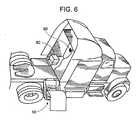
- FIG. 6is a simplified schematic diagram illustrating component placement in an over-the-road vehicle in accordance with one embodiment of the present invention.
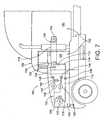
- FIG. 7is a simplified schematic diagram illustrating an electrically-driven compressor thermally coupled to a primary coolant loop in an over-the-road vehicle
- FIG. 8is a simplified schematic diagram illustrating a heat exchanger separating the primary loop of FIG. 7 into a high pressure coolant loop and a low pressure coolant loop in the over-the-road vehicle;
- FIG. 9is a simplified schematic diagram illustrating an electrically-driven compressor and a no-idle condenser thermally coupled to a primary coolant loop in the over-the-road vehicle;
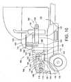
- FIG. 10is a simplified schematic diagram illustrating a heat exchanger separating the primary loop of FIG. 9 into a high pressure coolant loop and a low pressure coolant loop in the over-the-road vehicle;
- FIG. 11is a simplified schematic diagram illustrating primary and secondary air conditioning loops of the over-the-road vehicle sharing an evaporator.
- FIG. 12is a simplified schematic diagram illustrating a heat exchanger separating the primary loop of FIG. 11 into a high pressure coolant loop and a low pressure coolant loop in the over-the-road vehicle.
- FIG. 1illustrates, in simplified block diagrammatic form, an embodiment of an air conditioning system of particular applicability to an over-the-road or off-road commercial vehicle.
- the system 10 of the present inventionutilizes a brushless DC motor 12 to drive a variable speed compressor 14.
- This variable speed, brushless DC motor-driven compressor 14circulates refrigerant through a refrigerant-to-liquid or refrigerant-to-air heat exchanger 16 to an optional refrigerant receiver and dryer 18.
- the refrigerantthen passes through an expansion device 20 and a refrigerant-to-air heat exchanger 22 to cool the passenger compartment.
- a secondary parallel coolant loopis provided through expansion device 24 and refrigerant-to-air heat exchanger 26.
- Such secondary, parallel coolant loopsare often used to directly cool the sleeping compartment of an over-the-road vehicle's cab.
- the heat exchanger 26is typically smaller than the heat exchanger 22 as the volume for which it is responsible is reduced compared to the primary driver/passenger compartment of the cab.
- the two refrigerant coolant loopsmay be selectively coupled via a valve. The inclusion of such a valve allows, for example, only the sleeping compartment to be air conditioned when no occupant is in the main passenger compartment of the cab and vice versa to increase the efficiency of the system.
- the refrigerantthen passes through an optional refrigerant accumulator 28 before being returned to the compressor 14.
- variable speed compressor 14driven by brushless DC motor 12
- the vehicle's air conditioning systemmay be operated during both engine on and engine off (no idle) conditions.
- the provision of the variable speed compressor 14also allows the system to operate at a lower capacity during engine off operation to conserve the amount of stored energy available for usage by the system from the vehicle's batteries 34.
- the control for this operationis provided by an intelligent power generation management controller 30 that monitors various system parameters and the availability of power sources on the vehicle.
- the vehicle's air conditioning systemis now capable of being powered by either the vehicle's main electric power generation system 32, which is available while the vehicle's engine is operating, or by the electrical system while the engine is off by utilizing the stored electric power in the battery storage system 34.
- the intelligent power generation management controller 30also has the capability of utilizing shore power 36 or power from an auxiliary electric power unit 38, such as a genset or fuel cell.
- the use of the electric driven compressor 14provides the ability to modulate its output from full capacity to low capacity. This allows the use of a single air conditioning system that can be used both for high load on-road operations with the engine operating, and at a lower capacity with the engine off to continue to cool the passenger compartments. Coordination of this modulation is provided by the intelligent power generation controller 30, which reduces the speed of the compressor when only lower capacity power sources are available. This modulation extends the duration of available operation from such power sources. That is, with a reduced speed of the compressor, the electric power demand is reduced as well.
- an alternate embodiment of the system of the present inventionincludes a high pressure coolant loop 46 and a low pressure coolant loop 40 in a full HVAC system.
- the high pressure coolant loop 46is driven by the compressor 14, and may be constructed as a modular, sealed refrigeration power cell having fixed tubing with permanent connections.
- the low pressure coolant loop 40utilizes a low pressure coolant pump 42 to circulate the low pressure coolant through a refrigerant-to-liquid heat exchanger 44 that serves as the heat exchange medium between the high pressure coolant loop 46 and this secondary loop 40.
- a refrigerant-to-liquid heat exchanger 44serves as the heat exchange medium between the high pressure coolant loop 46 and this secondary loop 40.
- the primary high pressure coolant loop 46may be manufactured as a single integrated module having fixed tubing and permanent connections between the components thereof. As described in the above-identified patent, such a configuration minimizes the possibility of refrigerant leaks through high pressure couplings.
- the secondary low pressure coolant loop 40uses a treated liquid-to-air heat exchanger 48 located within the vehicle's interior to provide cooling to the passenger compartments.
- a coolant heater 50may be utilized in the secondary low pressure coolant loop 40.
- the intelligent power generation management controller 30need only operate the secondary loop coolant pump 42 and the coolant heater 50 to provide this functionality. That is, no power need be delivered to the variable speed motor driven compressor 14 in this mode of operation, thereby further reducing the power consumption during engine off operation and extending the period of time that such operation is available.
- an air heater 52may be provided in the air outlet duct 54 of the vehicle HVAC system.
- Thismay be a fuel fired heater (FFH) or a resistance-type heater.
- the intelligent power generation management controller 30need not operate either the high pressure coolant loop or the low pressure coolant loop, but instead only operate a circulation fan 56 and the air heater 52 to provide the necessary heating for the vehicle passenger compartments.
- This configurationprovides additional power consumption savings and allows for a longer duration operation of the system in the heating mode.
- the compressorIn the cooling mode of operation, the compressor will be operated to circulate refrigerant through the high pressure refrigerant-to-air or low pressure liquid-to-air heat exchanger 58.
- a mode door and/or temperature control door 60controls the flow of air through the duct 54 to regulate the temperature of the air flowing into the vehicle passenger compartments as is known in the art.
- the system of the present inventionutilizes an intelligent power generation management controller 30 to modulate the speed, and therefore the capacity, of the variable speed brushless DC motor driven compressor 14.
- This output controlcan modulate the compressor 14 between a maximum compressor speed and capacity 62 during, for example, engine on operation or operation with an unlimited input power source such as the vehicle electrical power generation system 32 or a shore power electrical system 36, and a minimum compressor speed and capacity 64 during, for example, periods of operation utilizing limited sources of electrical power such as the electric power battery storage system 34 or an electrical auxiliary power unit power system 38. Operation at any speed and capacity between these two points 62, 64 is available as controlled by the intelligent power generation management controller 30.
- This controller 30may also vary the modulation of compressor 14 when additional or different sources of power become available and as system parameters change to maintain optimal system performance.
- the controller 30may operate the compressor 14 at maximum compressor speed and capacity while the vehicle is being driven to maintain the temperature of the passenger compartment of the vehicle at a user selected temperature. As the vehicle is parked and the engine is turned off, the controller 30 will sense the loss of the vehicle electric power generation system 32 and will begin to utilize electric power from the electric power battery storage system 34 to drive the compressor. The controller 30 will then reduce the compressor speed and capacity so as to not draw an excessive amount of power from the battery. The speed and capacity of the compressor may be increased as needs demand as determined by the controller 30.
- the controller 30will not allow an amount of power to be discharged from the battery storage system 34 that would result in an insufficient amount of power remaining available to start the vehicle, or not allow an amount of power to be discharged from the battery storage system that will reduce the life of the system. As such a point is neared, the controller 30 will disable the power output to the compressor 14 thereby shutting down the HVAC system until and unless an additional source of power becomes available or the batteries are recharged. In one embodiment, this point is set at approximately 11.5 volts DC under load, although other set points may be appropriate based on the starting needs of the engine and battery life.
- the controller 30While the system is operating from the battery storage system 34, if the vehicle is connected to a shore power electrical system 36 the controller 30 will sense the availability of this new power source. The controller 30 will then begin utilizing this source to the exclusion of the battery system 34, and will increase the compressor speed and capacity as needed to maintain the temperature of the interior. If, instead, an auxiliary power unit on the vehicle is started, intelligent power generation management controller 30 will switch to this source of power to drive the compressor 14 to the exclusion of the battery storage system 34, and will increase the modulation of the compressor 14 as needed. However, unlike when the system is operated from the vehicle electric power generation system 32 or from the shore power electric system 36, the controller 30 may well reduce the modulation of the compressor 14 based upon the power draw and capacity of the APU power system 38.
- the controller 30recognizes that the APU power system 38 and the battery storage system 34 are limited resources that may be needed for other functions on the vehicle. As such, the controller 34 will ensure the conservation of some portion of these resources by disabling the HVAC system prior to exhaustion of these power sources.
- the intelligent power generation management controller 30monitors various system parameters to perform its modulation control function. Both the exterior ambient temperature 66 and the vehicle's interior ambient temperature 68 are monitored by the controller 30 to determine a compressor capacity to achieve and maintain the interior set point temperature. Typically, the larger the difference between the exterior and interior temperatures, the higher the capacity needed to maintain the differential. As the exterior ambient temperature 66 drops or the vehicle interior ambient temperature set point 68 rises the controller 30 may reduce the compressor speed and capacity and still maintain the user selected interior temperature.
- the controller 30also monitors the compressor power consumption 70 and the total system power consumption 72 in its modulation of the compressor speed and capacity. This information is used by the controller 30 to modulate the compressor 14 to ensure that the available power sources are not depleted beyond a predetermined power capacity for those times that a limited power source is being utilized. The controller 30 can reduce the compressor speed and capacity if the monitored power consumption exceeds appropriate levels. These parameters are also utilized to provide system protection from over load faults.
- the controller 30also monitors system parameters of the refrigeration system including the compressor speed 74 and the refrigerant system pressures and temperatures 76.
- the compressor speed signal 74is utilized in the closed loop proportional, integral, derivative (PID) control of the compressor modulation.
- the refrigerant system pressures and/or temperaturesare utilized as control parameters to regulate the compressor speed and capacity so that the power utilization is optimized. That is, the compressor modulation may be reduced once a temperature has been reached within the system to adequately cool the interior passenger compartments. Indeed, the compressor may be stopped altogether while the heat exchanger that cools the passenger compartments is at a temperature sufficient to provide adequate cooling. Once the temperature of this heat exchanger rises above a level sufficient to provide adequate cooling, the controller 30 may once again start the compressor 14 to reduce this temperature.
- the system parametersalso provide the controller 30 with the ability to detect faults within the system that reduce its ability to cool the interior compartment and that increase its power consumption.
- System status display and control inputsmay be provided between the controller 30 and the operator via a user input/output display 78 within the passenger compartment.
- a user input/output display 78within the passenger compartment.
- communication of control parameters from the usermay be provided to the controller 30 by means of a serial data link.
- the display of system control and status informationmay be provided by the controller 30 to the display 78 by this serial data link.
- Control parameters from the userwill typically include the desired operating mode of the HVAC system including off, heat, and cool modes of operation. Likewise a temperature setting may also be input through this I/O device 78.
- the usermay also select which of the available power sources should be utilized to drive the variable speed compressor.
- the controller 30may also provide switching between available power sources as a source is depleted, or may query the user for authorization before providing such automatic source power transfer.
- Fan speed and interior compartment selectionmay also be controlled via the user I/O display or controls 78.
- System status informationmay also be displayed on the user I/O display 78 including interior and exterior temperatures, fan speed, mode selection, remaining available power, selected power source, available power sources, status and warning messages, etc.
- the systemallows adjustment of the following parameters via the display/control 78: compressor minimum control output; compressor maximum control output; maximum current draw; indoor unit minimum speed output; battery cutout voltage; compressor cooling control parameters kp, ki, and kd; and indoor fan heating control parameters Kp, Ki, and Kd.
- These parametersprovide the proportional, integral, and derivative, or rate gains for the control PID equations.
- the following parametersare reported to the display 78: operating mode; set temperature; cab temperature; discharge air temperature; battery voltage; battery current; and compressor commanded speed.
- the intelligent power generation and management controller 30processes the user inputs to determine the operational mode of the HVAC system.
- the controller 30commands a heater, e.g. coolant heater 50 illustrated in Fig. 2 or air heater 52 illustrated in Fig. 3 , to turn on.
- These heatersmay be fuel fired heaters or electric resistance heaters as appropriate.
- the controller 30also controls the interior fan speed via a pulse width modulated (PWM) PID control loop in order to maintain the interior cab temperature at the set point. If, however, the user selects a cooling mode of operation, the condenser fan and pump outputs are turned on and the interior compartment fan is set to 100%.
- PWMpulse width modulated
- the compressor speedis set to the minimum capacity and speed setting.
- the controller 30then modulates the speed and capacity of the compressor 14 to maintain the cab temperature at the user defined set point via the PID control, except when certain conditions are encountered. These conditions include a high current/high load limit that reduces the compressor speed if the supply current exceeds a predefined current limit. In one embodiment, this current limit is set at 40 amps.
- the compressor speedis set to zero, until the discharge air temperature is above the set point for more than a predetermined amount of time. Further, if the pressure sensing indicates a fault within the refrigeration the requested compressor speed will also be set to zero. The compressor will be disabled for a predetermined period of time before the compressor is allowed to be operated. Finally, if the battery voltage drops below a predetermined value load the controller 30 will disable all outputs until power has been cycled to the controller 30 or an alternate source of power becomes available.
- the system of the present inventionprovides significant advantages when integrated into a vehicle's HVAC system, many currently existing vehicles that already have a HVAC system installed would also benefit from such a system. However, the cost of removing a vehicle's current HVAC system and reinstalling the system of the present invention may well be cost prohibitive. Therefore, in an alternate embodiment of the present invention the components of the system are modularized for installation on a vehicle in addition to the currently existing HVAC system that is operable only during engine on operation. With this embodiment, the passenger compartment temperature may be controlled without running the engine.
- a sealed refrigeration systemwith the variable speed brushless DC compressor and integrated coolant heater.
- This sealed unitmay be installed in various locations within the interior or exterior of the vehicle.
- the installation of the sealed moduleis illustrated as being external to the engine and passenger compartments.
- an inside HVAC unit 80including a heat exchanger and fan is installed to provide the air conditioning of the passenger compartment.
- This interior unit 80may also include an air heater if a coolant heater is not included with sealed system 10.
- the intelligent power generation management controller 30is also installed within the passenger compartment. Through this controller 30 the users may control the system of the present invention and receive read out information.
- an air conditioning system 100is illustrated.
- the air conditioning system 100is generally for use in a vehicle 102 (e.g., an over-the-road vehicle) having an engine (not shown).
- the air conditioning system 100utilizes some components when the engine of the vehicle 102 is operating and other components when the engine of the vehicle is not operating. In at least one situation, one or more components within the air conditioning system 100 are shared between "engine on” and “engine off” systems.
- the air conditioning system 100generally comprises a primary air conditioning loop 104 and an electrically-driven compressor 106.
- the primary air conditioning loop 104is usually installed by the manufacturer of the vehicle 102.
- the primary air conditioning loop 104includes typical air conditioning components such as, for example, a belt-driven compressor 108, a condenser 110, an expansion valve 112, and an evaporator 114. These components are thermally coupled together by high-pressure refrigerant lines 116. Therefore, refrigerant is permitted to circulate through the primary air conditioning loop 104 in various states and at various temperatures and pressures.
- the primary air conditioning loop 104also includes a belt-driven air mover 118 (e.g., a fan) positioned proximate the condenser 110.
- the belt-driven air mover 118moves air over the condenser 110 to extract and remove heat from the refrigerant.
- the primary air conditioning loop 104also includes an electric air mover 120 positioned proximate the evaporator 114. The electric air mover 120 moves air over the evaporator 114 such that heat is absorbed from the interior 120 of the vehicle 122.
- the belt-driven compressor 108 and the condenser 110are disposed on one side of a firewall 124 and within an engine compartment 126 of the vehicle 102.
- the expansion valve 112 and the evaporator 114are disposed on the other side of the firewall 124 and in thermal communication with the interior 120 of the vehicle 102.
- high-pressure fittings(not shown) are installed by the manufacture of the vehicle 102.
- the interior 122 of the vehicle 102is divided into a cab compartment 128 and a sleeper compartment 130.
- an additional sleeper evaporator 132is often included in the primary air conditioning loop 104. As shown in FIG. 7 , the sleeper evaporator 132 is thermally coupled to the evaporator 114 by the high-pressure lines 116.
- An additional electric air mover 134is positioned proximate the sleeper evaporator 132 to move air over the sleeper evaporator such that heat is absorbed from the sleeper compartment 130.
- the evaporator 114is placed in thermal communication with the cab compartment 128 to cool that area while the sleeper evaporator 132 is placed in thermal communication with the sleeper compartment 130 to cool that area.
- the use of the sleeper evaporator 132 and the evaporator 114permits the entire interior 122 of the vehicle 102 to be cooled. If desired, the sleeper compartment 130 of the vehicle is cooled while the cab compartment 128 is not, and vice versa.
- a metering devicee.g., a coolant flow control valve
- a thermostatic controlor other like device is employed to route refrigerant. Therefore, refrigerant is equally or disproportionately delivered to one or both of the evaporator 114 and sleeper evaporator 132.
- the sleeper compartment 130is the only compartment that is cooled. For this to occur, the sleeper compartment 130 is usually blocked off from the cab compartment 128 by, for example, a door or curtain. Thereafter, all or a larger portion of the refrigerant is routed to the sleeper evaporator 132 compared to that amount of refrigerant routed to the evaporator 114. In addition, only the electric air mover 134 is operated while the electric air mover 120 remains idle. The need to cool only the sleeper compartment 130 in this manner arises when, for example, the engine of the vehicle 102 is not operating and the driver of the vehicle is sleeping in the sleeper compartment at night. As a result of selectively cooling only a portion of the interior 122, in this case the sleeper compartment 130, the source of electric power is not unnecessarily drained for the benefit of unoccupied areas.
- the primary air conditioning loop 104further includes a receiver/dryer 136 (collectively, "dryer").
- the dryer 136contains a desiccant, which is a chemical that attracts moisture. The desiccant inhibits corrosive acids from forming in case a small amount of water and the refrigerant happen to combine. If need be, the dryer 136 also serves as temporary holding tank for liquid refrigerant.
- the primary air conditioning loop 104further includes an accumulator 138.
- the accumulator 138 and the dryer 136generally serve similar purposes, the dryer 136 is typically connected to an outlet of the condenser 110.
- the accumulator 138is attached to an outlet of the evaporator 114 and prevents liquid refrigerant from being drawn into the compressor (e.g., compressors 106, 108).
- the electrically-driven compressor 106is shown thermally coupled to the primary air conditioning loop 104.
- the electrically-driven compressor 106is arranged in parallel with the belt-driven compressor 108.
- Valves 140, 142are disposed in the high pressure refrigerant lines 116 upstream of each of the compressors 106, 108.
- These valves 140, 142are, in one embodiment, solenoid valves.
- valves 140, 142selectively permit or restrict a flow of refrigerant to each of the compressors 106, 108.
- valve 140when the engine of the vehicle 102 is operating, valve 140 is open and the valve 142 is closed such that the refrigerant is routed to the belt-driven compressor 108. In this situation, the electrically-driven compressor 106 is idle.
- valve 142when the engine of the vehicle 102 is not operating, valve 142 is open and valve 140 is closed such that the refrigerant is routed to the electrically-driven compressor 106. In this situation, the belt-driven compressor 108 is idle. In each instance, the refrigerant flowing through the primary air conditioning loop 104 is compressed by one of the compressors 106, 108 such that cooling of the interior 122 of the vehicle 102 is able to take place.
- the electric air mover 144is employed to circulate air any time the electrically-driven compressor 108 is being relied upon.
- the electric air mover 144substitutes for the belt-driven air mover 118 to circulate air over the condenser 110 during no-idle operation.
- the electrically-driven compressor 106shares numerous air conditioning components with the primary air conditioning loop 104 such as, for example, the condenser 110, the evaporator 114, the expansion valve 112, the dryer 136, and the like. Therefore, the no-idle system cooling the interior 122 of the vehicle 102 need not require duplicate air conditioning components that are already readily available via the primary air conditioning loop 104. Because additional components are not needed, the overall air conditioning system in the vehicle is less expensive, less prone to mechanical failures, and the like.
- the electrically-driven compressor 106is operably coupled to a controller 146.
- the controller 146like controller 30 illustrated in FIG. 1 , is able to control the speed of the electrically-driven compressor 106.
- the controlis based on a power capacity of a source of power coupled to that compressor.
- the various sources of electrical power input into the controller 146are from, for example, an auxiliary power unit, shore power, a vehicle electric power system, and batteries. In other embodiments, the control is based on the cooling needs.
- a heat exchanger 148is used to separate the primary air conditioning loop 104 of FIG. 7 into a high pressure coolant loop 150 and a low pressure coolant loop 152. As noted above with regard to FIG. 2 , this eliminates the need to use high-pressure fittings when passing the high pressure lines 116 through the firewall 124. Therefore, low pressure coolant lines 154, which are more reliable and less susceptible to leaks, thermally couple components in the low pressure coolant loop 152.
- the low pressure coolant loop 152includes a coolant pump 156.
- the coolant pump 156is utilized to circulate the coolant under low pressure conditions.
- the coolant pump 156is used because the low pressure coolant loop 152 is without a compressor to pressurize and move the refrigerant.
- the low pressure coolant loop 152also includes a coolant heater 158 to warm the coolant. This is particularly beneficial when the vehicle 102 is located in cold environments.
- the primary air conditioning loop 104includes both an electrically-driven compressor 106 and a no-idle condenser 160.
- the no-idle condenser 160has the same basic function as the condenser 110, yet the no idle condenser is operable when the engine of the vehicle 102 is not operating. In other words, when the engine of the vehicle 102 is not running, the no-idle condenser 160 is relied upon.
- the electrically-driven compressor 106 and the no-idle condenser 160share numerous air conditioning components with the primary air conditioning loop 104 such as, for example, the evaporator 114, the expansion valve 112, the dryer 136, and the like.
- the no-idle system cooling the interior 122 of the vehicle 102need not contain or use duplicate air conditioning components because such components are already readily available within the primary air conditioning loop 104.
- the electrically-driven compressor 106 and the no-idle condenser 160are thermally coupled in series with each other and in parallel with a combination of the belt-driven compressor 108 and the condenser 110 which are also thermally coupled in series with each other.
- the valves 140, 142selectively permit or restrict a flow of refrigerant to the compressor 108 and the condenser 110 in one branch of the circuit or the compressor 106 and the condenser 160 in a second branch 105 of the circuit.
- valve 140is open and the valve 142 is closed such that the refrigerant is routed to the belt-driven compressor 108 and the condenser 110.
- valve 142is open and valve 140 is closed such that the refrigerant is routed to the electrically-driven compressor 106 and the condenser 160 in the second branch 105.
- the belt-driven compressor 108 and the condenser 110are idle.
- the refrigerant flowing through the primary air conditioning loop 104is compressed by one of the compressors 106, 108 such that cooling of the interior 122 of the vehicle 102 is able to take place.
- a heat exchanger 148is used to separate the primary air conditioning loop 104 of FIG. 9 into a high pressure coolant loop 150 and a low pressure coolant loop 152. Again, this eliminates the need to use high-pressure fittings when passing the high pressure lines 116 through the firewall 124. Therefore, low pressure coolant lines 154 are employed to thermally couple components in the low pressure coolant loop 152.
- the primary air conditioning loop 104shares a multi-circuited evaporator 162 with a secondary air conditioning loop 164.
- the secondary air conditioning loop 164is quite similar to the system 10, which is illustrated in FIG. 1 , in that the secondary air conditioning loop includes an electrically-driven compressor 166, a controller 168, an expansion valve 170, a no-idle condenser 172, an electrically-driven fan 174 disposed adjacent the no-idle condenser, and a dryer 176.
- the secondary air conditioning loop 164also includes the multi-circuited evaporator 162 which is not found within the system 10 of FIG. 1 .
- the evaporator 162is a dual-circuited multi-refrigerant evaporator.
- the secondary air conditioning loop 164 and a portion of the multi-circuited evaporator 162are disposed in a hermetically sealed housing 178.
- the other portion of the evaporator 162projects out of the housing 178, is in thermal communication with the interior 122, and is able to be coupled to the existing refrigerant lines found in the vehicle. Therefore, the modular secondary air conditioning loop 164 is easily and conveniently attached to or disposed within the vehicle 102 (e.g., in a side compartment of the vehicle 102, in the battery compartment, and the like).
- an electrically-driven air mover 180is located within the housing 178 to move air over the evaporator 162 while another electrically-driven air mover 182 is disposed outside the housing to do the same. Therefore, air is circulated across at least some portion of the evaporator 162 when the engine of the vehicle 102 is operating and when it is not operating to condition the air within the interior 122 of the sleeper compartment 130.
- Installation of the secondary air conditioning loop 164 into an existing vehicle 102is performed quite simply by removing the typical single-circuit sleeper evaporator from the sleeper compartment 130 of the vehicle, discarding it, and then coupling the existing refrigerant lines (e.g., refrigerant lines 116) to the circuit of the dual-circuited evaporator 162. Because of the ease of installation, a no-idle air conditioning system is quickly and easily installed in the vehicle 102 without the components and structure of the vehicle needing substantial alteration or modification.
- the multi-circuited evaporator 166is in thermal communication with the sleeper compartment 130. Even so, the multi-circuited evaporator 166 is, in another embodiment, in thermal communication with the cab compartment 128 or the whole of the interior 122 of the vehicle 102.
- a heat exchanger 148is used to separate the primary air conditioning loop 104 of FIG. 11 into a high pressure coolant loop 150 and a low pressure coolant loop 152. Again, this eliminates the need to use high-pressure fittings when passing the high pressure lines 116 through the firewall 124. Therefore, low pressure coolant lines 154 are employed to thermally couple components in the low pressure coolant loop 152. As depicted in FIG. 12 , due to the use of the heat exchanger 148, the multi-circuit evaporator 162 is coupled to the low pressure coolant lines 154 in lieu of the high pressure coolant lines 116 as shown in FIG. 11 .
- the compressor 166 in the secondary air conditioning loop 164 ( FIGS. 11 and 12 ) or the compressor 106 thermally coupled to the primary air conditioning loop 104 ( FIGS. 7-10 )is an alternating-current (AC) compressor driven by a frequency drive.
- ACalternating-current
Landscapes
- Physics & Mathematics (AREA)
- Thermal Sciences (AREA)
- Engineering & Computer Science (AREA)
- Mechanical Engineering (AREA)
- Air-Conditioning For Vehicles (AREA)
Abstract
Description
- The present invention relates generally to over-the-road and off-road vehicle air conditioning systems, and more particularly to vehicle-mounted heating, ventilation, and air conditioning (HVAC) systems utilizing variable speed motor driven compressors and controls therefor.
- The global economic expansion has stressed the transportation industry's ability to keep up with the shipping demands for raw materials and finished products. Indeed, the demand for qualified tractor-trailer drivers has far outstripped the ability of the industry to recruit and train individuals to fill the demand of the marketplace. As a result, the demand of the transportation industry to utilize the existing personnel and vehicles has resulted in increased time spent on the road and in the vehicles in an attempt to meet the market demands.
- In an effort to maintain the safety of the highways, regulations governing the amount of time that a driver may spend behind the wheel have been instituted. When such maximum times have been reached, the driver is required to take his vehicle off the road and rest. The number of trucks pulled over at toll plazas, weigh stations, and rest stops illustrates the compliance with such regulations. However, these locations often do not provide anywhere for the drivers to rest, necessitating continued occupancy within the vehicle.
- In response to the needs of the transportation industry and in recognition of the locations where drivers are forced to rest, over-the-road vehicle manufacturers have continued to increase the emphasis on ergonomic factors in the design and manufacture of their vehicles. Indeed, the interior of a modem over-the-road vehicle contains many features to minimize the stress and fatigue placed on the drivers during the operation of the vehicle. These features include vibration dampers and lumbar supports in the seats, increased sound insulation, and heating, ventilation, and air conditioning (HVAC) systems that provide a comfortable environment for the driver. To accommodate the required rest periods, and in recognition of the increased usage of driving teams, which typically include two individuals - one who drives while the other sleeps - many over-the-road vehicles include a sleeping compartment. This sleeping compartment is also temperature controlled so that time spent therein provides the occupant with a restful experience.
- Unfortunately, the current state-of-the-art heating and air conditioning systems utilize engine-belt driven compressors for the air conditioning system to circulate and pump the refrigerant throughout the vehicle to cool the passenger compartments. An engine-belt driven pump is also utilized to circulate the engine waste heat throughout the passenger compartments when heating is required. While such systems are ideally suited to provide a temperature controlled environment during operation of the vehicle, neither of such systems is able to operate when the engine is turned off.
- As a result of the inability of the current state of the art of vehicle HVAC systems to operate while the vehicle's engine is turned off, the over-the-road vehicle operators are forced to choose between two less than ideal situations while trying to rest. First, they may choose to continuously run their vehicle's engine so that they may have heating or air conditioning while they rest. Alternatively, they may choose to turn off their engine and try to rest in a non-temperature controlled environment, although temperatures can often reach extremes of high and low depending on where the vehicle happens to be when a required rest period is reached. While the first option improves safety by providing a comfortable resting environment for the driver, it greatly increases the cost of operating the over-the-road vehicle as the engine is continued to run, which bums additional fuel, simply to operate the heating or air conditioning system. Similarly, while the second option does not increase the cost of operating the vehicle because the engine is turned off, the driver may not fully be able to rest in an environment of temperature extremes, thus potentially reducing the safety of the operation of the vehicle.
- There exists, therefore, a need in the art for a vehicle heating, ventilation, and air conditioning (HVAC) system that is able to provide conditioning of the interior of the vehicle, not only during periods of engine operation, but also during engine off or no-idle conditions.
- Published patent application
EP 1504227 A , assigned to the assignee of the instant application, discloses an air conditioning system for use in a vehicle that allows operation during both engine on and engine off conditions. The system utilizes a variable speed, motor driven compressor controlled by an intelligent power management controller that selects from one of the available sources of power to drive the compressor, substantially as described below with reference toFigures 1 to 6 . - In view of the above, the present invention provides a new and improved heating, ventilating, and air conditioning (HVAC) system for an over-the-road vehicle that may be operated regardless of the operational state of the engine. That is, the instant invention provides a new and improved HVAC system that may be operated to condition the interior compartments of an over-the-road vehicle while the engine is running and while the engine is in a no-idle (off) condition. In general, the HVAC system efficiently shares one or more typical air conditioning components with those already found in the vehicle. In one instance, the HVAC system operates an electrically-driven compressor when a belt-driven compressor is idle. In another embodiment, the HVAC system operates both an electrically-driven compressor and a no-idle condenser when a belt-driven compressor and condenser are idle. In yet another embodiment, the HVAC system shares an evaporator.
- In one aspect, the invention provides an air conditioning system for use in a vehicle having an engine, which includes a primary air conditioning loop and an electrically-driven compressor. The primary air conditioning loop has a belt-driven compressor operable when the engine of the vehicle is operating. The electrically-driven compressor is thermally coupled to the primary air conditioning loop and is operable when the engine of the vehicle is not operating.
- In another aspect, the invention provides an air conditioning system for use in a vehicle having an engine, which includes a primary air conditioning loop and a secondary air conditioning loop. The a primary air conditioning loop is operable when an engine of the vehicle is operating and includes an evaporator. The secondary air conditioning loop is operable when the engine of the vehicle is not operating and shares the evaporator with the primary air conditioning loop.
- In yet another aspect, the invention provides a method of cooling a vehicle having a primary air conditioning loop operable when an engine of the vehicle is operating and a secondary air conditioning loop operable when an engine of the vehicle is not operating. The method includes the step of sharing at least one air conditioning component between the primary and secondary air conditioning systems.
- Other aspects, objectives and advantages of the invention will become more apparent from the following detailed description when taken in conjunction with the accompanying drawings.
- The accompanying drawings incorporated in and forming a part of the specification illustrate several aspects of the present invention and, together with the description, serve to explain the principles of the invention. In the drawings:
FIG. 1 is a simplified single line block diagram illustrating coolant flow and system component interconnections in an air conditioning system constructed in accordance with the teachings of the present invention;FIG. 2 illustrates an alternate embodiment of the invention forming a HVAC system capable of providing both heating and cooling of a passenger compartment of an over-the-road vehicle;FIG. 3 is a simplified air flow diagram illustrating an alternate embodiment of an HVAC system constructed in accordance with the teachings of the present invention incorporating an air heater;FIG. 4 is a simplified block diagram illustrating alternate power source utilization and compressor capacity modulation provided by the intelligent power generation management controller of an embodiment of the present invention;FIG. 5 is a simplified block diagram illustrating control parameter utilization and compressor capacity modulation provided by the intelligent power generation management controller of an embodiment of the present invention; andFIG. 6 is a simplified schematic diagram illustrating component placement in an over-the-road vehicle in accordance with one embodiment of the present invention;FIG. 7 is a simplified schematic diagram illustrating an electrically-driven compressor thermally coupled to a primary coolant loop in an over-the-road vehicle;FIG. 8 is a simplified schematic diagram illustrating a heat exchanger separating the primary loop ofFIG. 7 into a high pressure coolant loop and a low pressure coolant loop in the over-the-road vehicle;FIG. 9 is a simplified schematic diagram illustrating an electrically-driven compressor and a no-idle condenser thermally coupled to a primary coolant loop in the over-the-road vehicle;FIG. 10 is a simplified schematic diagram illustrating a heat exchanger separating the primary loop ofFIG. 9 into a high pressure coolant loop and a low pressure coolant loop in the over-the-road vehicle;FIG. 11 is a simplified schematic diagram illustrating primary and secondary air conditioning loops of the over-the-road vehicle sharing an evaporator; andFIG. 12 is a simplified schematic diagram illustrating a heat exchanger separating the primary loop ofFIG. 11 into a high pressure coolant loop and a low pressure coolant loop in the over-the-road vehicle.- While the invention will be described in connection with certain preferred embodiments, there is no intent to limit it to those embodiments. On the contrary, the intent is to cover all alternatives, modifications and equivalents as included within the spirit and scope of the invention as defined by the appended claims.
Figure 1 illustrates, in simplified block diagrammatic form, an embodiment of an air conditioning system of particular applicability to an over-the-road or off-road commercial vehicle. Unlike conventional vehicle air conditioning systems, thesystem 10 of the present invention utilizes abrushless DC motor 12 to drive avariable speed compressor 14. This variable speed, brushless DC motor-drivencompressor 14 circulates refrigerant through a refrigerant-to-liquid or refrigerant-to-air heat exchanger 16 to an optional refrigerant receiver anddryer 18. The refrigerant then passes through anexpansion device 20 and a refrigerant-to-air heat exchanger 22 to cool the passenger compartment.- In one embodiment of the present invention, a secondary parallel coolant loop is provided through
expansion device 24 and refrigerant-to-air heat exchanger 26. Such secondary, parallel coolant loops are often used to directly cool the sleeping compartment of an over-the-road vehicle's cab. As such, theheat exchanger 26 is typically smaller than theheat exchanger 22 as the volume for which it is responsible is reduced compared to the primary driver/passenger compartment of the cab. While not illustrated inFig. 1 , the two refrigerant coolant loops may be selectively coupled via a valve. The inclusion of such a valve allows, for example, only the sleeping compartment to be air conditioned when no occupant is in the main passenger compartment of the cab and vice versa to increase the efficiency of the system. The refrigerant then passes through an optionalrefrigerant accumulator 28 before being returned to thecompressor 14. - By utilizing a
variable speed compressor 14 driven bybrushless DC motor 12, the vehicle's air conditioning system may be operated during both engine on and engine off (no idle) conditions. The provision of thevariable speed compressor 14 also allows the system to operate at a lower capacity during engine off operation to conserve the amount of stored energy available for usage by the system from the vehicle'sbatteries 34. The control for this operation is provided by an intelligent powergeneration management controller 30 that monitors various system parameters and the availability of power sources on the vehicle. - In this way, the vehicle's air conditioning system is now capable of being powered by either the vehicle's main electric
power generation system 32, which is available while the vehicle's engine is operating, or by the electrical system while the engine is off by utilizing the stored electric power in thebattery storage system 34. Additionally, the intelligent powergeneration management controller 30 also has the capability of utilizingshore power 36 or power from an auxiliaryelectric power unit 38, such as a genset or fuel cell. - In the
system 10 of the present invention, the use of the electric drivencompressor 14 provides the ability to modulate its output from full capacity to low capacity. This allows the use of a single air conditioning system that can be used both for high load on-road operations with the engine operating, and at a lower capacity with the engine off to continue to cool the passenger compartments. Coordination of this modulation is provided by the intelligentpower generation controller 30, which reduces the speed of the compressor when only lower capacity power sources are available. This modulation extends the duration of available operation from such power sources. That is, with a reduced speed of the compressor, the electric power demand is reduced as well. - As illustrated in
Fig.2 , an alternate embodiment of the system of the present invention includes a highpressure coolant loop 46 and a lowpressure coolant loop 40 in a full HVAC system. The highpressure coolant loop 46 is driven by thecompressor 14, and may be constructed as a modular, sealed refrigeration power cell having fixed tubing with permanent connections. The lowpressure coolant loop 40 utilizes a lowpressure coolant pump 42 to circulate the low pressure coolant through a refrigerant-to-liquid heat exchanger 44 that serves as the heat exchange medium between the highpressure coolant loop 46 and thissecondary loop 40. Such a configuration is described inU.S. Patent No. 6,276,161 , entitled Modular Low Pressure Delivery Vehicle Air Conditioning System, assigned to the assignee of the instant application. In such a configuration, the primary highpressure coolant loop 46 may be manufactured as a single integrated module having fixed tubing and permanent connections between the components thereof. As described in the above-identified patent, such a configuration minimizes the possibility of refrigerant leaks through high pressure couplings. - As illustrated in
Fig. 2 , the secondary lowpressure coolant loop 40 uses a treated liquid-to-air heat exchanger 48 located within the vehicle's interior to provide cooling to the passenger compartments. To provide heating of the vehicle passenger compartments acoolant heater 50 may be utilized in the secondary lowpressure coolant loop 40. During such heating operation, the intelligent powergeneration management controller 30 need only operate the secondaryloop coolant pump 42 and thecoolant heater 50 to provide this functionality. That is, no power need be delivered to the variable speed motor drivencompressor 14 in this mode of operation, thereby further reducing the power consumption during engine off operation and extending the period of time that such operation is available. - In an alternate embodiment illustrated in
Fig. 3 , anair heater 52 may be provided in theair outlet duct 54 of the vehicle HVAC system. This may be a fuel fired heater (FFH) or a resistance-type heater. In this configuration, the intelligent powergeneration management controller 30 need not operate either the high pressure coolant loop or the low pressure coolant loop, but instead only operate acirculation fan 56 and theair heater 52 to provide the necessary heating for the vehicle passenger compartments. This configuration provides additional power consumption savings and allows for a longer duration operation of the system in the heating mode. In the cooling mode of operation, the compressor will be operated to circulate refrigerant through the high pressure refrigerant-to-air or low pressure liquid-to-air heat exchanger 58. A mode door and/ortemperature control door 60 controls the flow of air through theduct 54 to regulate the temperature of the air flowing into the vehicle passenger compartments as is known in the art. - As discussed briefly above and as illustrated in
FIG. 4 , the system of the present invention utilizes an intelligent powergeneration management controller 30 to modulate the speed, and therefore the capacity, of the variable speed brushless DC motor drivencompressor 14. This output control can modulate thecompressor 14 between a maximum compressor speed andcapacity 62 during, for example, engine on operation or operation with an unlimited input power source such as the vehicle electricalpower generation system 32 or a shore powerelectrical system 36, and a minimum compressor speed andcapacity 64 during, for example, periods of operation utilizing limited sources of electrical power such as the electric powerbattery storage system 34 or an electrical auxiliary powerunit power system 38. Operation at any speed and capacity between these twopoints generation management controller 30. Thiscontroller 30 may also vary the modulation ofcompressor 14 when additional or different sources of power become available and as system parameters change to maintain optimal system performance. - For example, the
controller 30 may operate thecompressor 14 at maximum compressor speed and capacity while the vehicle is being driven to maintain the temperature of the passenger compartment of the vehicle at a user selected temperature. As the vehicle is parked and the engine is turned off, thecontroller 30 will sense the loss of the vehicle electricpower generation system 32 and will begin to utilize electric power from the electric powerbattery storage system 34 to drive the compressor. Thecontroller 30 will then reduce the compressor speed and capacity so as to not draw an excessive amount of power from the battery. The speed and capacity of the compressor may be increased as needs demand as determined by thecontroller 30. However, thecontroller 30 will not allow an amount of power to be discharged from thebattery storage system 34 that would result in an insufficient amount of power remaining available to start the vehicle, or not allow an amount of power to be discharged from the battery storage system that will reduce the life of the system. As such a point is neared, thecontroller 30 will disable the power output to thecompressor 14 thereby shutting down the HVAC system until and unless an additional source of power becomes available or the batteries are recharged. In one embodiment, this point is set at approximately 11.5 volts DC under load, although other set points may be appropriate based on the starting needs of the engine and battery life. - While the system is operating from the
battery storage system 34, if the vehicle is connected to a shore powerelectrical system 36 thecontroller 30 will sense the availability of this new power source. Thecontroller 30 will then begin utilizing this source to the exclusion of thebattery system 34, and will increase the compressor speed and capacity as needed to maintain the temperature of the interior. If, instead, an auxiliary power unit on the vehicle is started, intelligent powergeneration management controller 30 will switch to this source of power to drive thecompressor 14 to the exclusion of thebattery storage system 34, and will increase the modulation of thecompressor 14 as needed. However, unlike when the system is operated from the vehicle electricpower generation system 32 or from the shore powerelectric system 36, thecontroller 30 may well reduce the modulation of thecompressor 14 based upon the power draw and capacity of theAPU power system 38. That is, thecontroller 30 recognizes that theAPU power system 38 and thebattery storage system 34 are limited resources that may be needed for other functions on the vehicle. As such, thecontroller 34 will ensure the conservation of some portion of these resources by disabling the HVAC system prior to exhaustion of these power sources. - As illustrated in
Fig. 5 , the intelligent powergeneration management controller 30 monitors various system parameters to perform its modulation control function. Both the exteriorambient temperature 66 and the vehicle's interiorambient temperature 68 are monitored by thecontroller 30 to determine a compressor capacity to achieve and maintain the interior set point temperature. Typically, the larger the difference between the exterior and interior temperatures, the higher the capacity needed to maintain the differential. As the exteriorambient temperature 66 drops or the vehicle interior ambient temperature setpoint 68 rises thecontroller 30 may reduce the compressor speed and capacity and still maintain the user selected interior temperature. - The
controller 30 also monitors thecompressor power consumption 70 and the totalsystem power consumption 72 in its modulation of the compressor speed and capacity. This information is used by thecontroller 30 to modulate thecompressor 14 to ensure that the available power sources are not depleted beyond a predetermined power capacity for those times that a limited power source is being utilized. Thecontroller 30 can reduce the compressor speed and capacity if the monitored power consumption exceeds appropriate levels. These parameters are also utilized to provide system protection from over load faults. - The
controller 30 also monitors system parameters of the refrigeration system including thecompressor speed 74 and the refrigerant system pressures andtemperatures 76. Thecompressor speed signal 74 is utilized in the closed loop proportional, integral, derivative (PID) control of the compressor modulation. The refrigerant system pressures and/or temperatures are utilized as control parameters to regulate the compressor speed and capacity so that the power utilization is optimized. That is, the compressor modulation may be reduced once a temperature has been reached within the system to adequately cool the interior passenger compartments. Indeed, the compressor may be stopped altogether while the heat exchanger that cools the passenger compartments is at a temperature sufficient to provide adequate cooling. Once the temperature of this heat exchanger rises above a level sufficient to provide adequate cooling, thecontroller 30 may once again start thecompressor 14 to reduce this temperature. In this way, the draw from the available power sources is minimized while still achieving the goal of providing adequate passenger cooling with the limited power sources available to drive the system. The system parameters also provide thecontroller 30 with the ability to detect faults within the system that reduce its ability to cool the interior compartment and that increase its power consumption. - System status display and control inputs may be provided between the
controller 30 and the operator via a user input/output display 78 within the passenger compartment. When such adisplay 78 is utilized, communication of control parameters from the user may be provided to thecontroller 30 by means of a serial data link. Likewise, the display of system control and status information may be provided by thecontroller 30 to thedisplay 78 by this serial data link. Control parameters from the user will typically include the desired operating mode of the HVAC system including off, heat, and cool modes of operation. Likewise a temperature setting may also be input through this I/O device 78. - In one embodiment of the present invention, the user may also select which of the available power sources should be utilized to drive the variable speed compressor. The
controller 30 may also provide switching between available power sources as a source is depleted, or may query the user for authorization before providing such automatic source power transfer. Fan speed and interior compartment selection may also be controlled via the user I/O display or controls 78. System status information may also be displayed on the user I/O display 78 including interior and exterior temperatures, fan speed, mode selection, remaining available power, selected power source, available power sources, status and warning messages, etc. - In one embodiment of the present invention, the system allows adjustment of the following parameters via the display/control 78: compressor minimum control output; compressor maximum control output; maximum current draw; indoor unit minimum speed output; battery cutout voltage; compressor cooling control parameters kp, ki, and kd; and indoor fan heating control parameters Kp, Ki, and Kd. These parameters provide the proportional, integral, and derivative, or rate gains for the control PID equations. In this embodiment, the following parameters are reported to the display 78: operating mode; set temperature; cab temperature; discharge air temperature; battery voltage; battery current; and compressor commanded speed.
- During operation, the intelligent power generation and
management controller 30 processes the user inputs to determine the operational mode of the HVAC system. When the heating mode of operation is commanded by a user in the engine off (no idle) condition, thecontroller 30 commands a heater,e.g. coolant heater 50 illustrated inFig. 2 orair heater 52 illustrated inFig. 3 , to turn on. These heaters may be fuel fired heaters or electric resistance heaters as appropriate. Thecontroller 30 also controls the interior fan speed via a pulse width modulated (PWM) PID control loop in order to maintain the interior cab temperature at the set point. If, however, the user selects a cooling mode of operation, the condenser fan and pump outputs are turned on and the interior compartment fan is set to 100%. Initially, the compressor speed is set to the minimum capacity and speed setting. Thecontroller 30 then modulates the speed and capacity of thecompressor 14 to maintain the cab temperature at the user defined set point via the PID control, except when certain conditions are encountered. These conditions include a high current/high load limit that reduces the compressor speed if the supply current exceeds a predefined current limit. In one embodiment, this current limit is set at 40 amps. - Similarly, if the requested compressor speed is at a minimum and the discharge air temperature is below the temperature set point, the compressor speed is set to zero, until the discharge air temperature is above the set point for more than a predetermined amount of time. Further, if the pressure sensing indicates a fault within the refrigeration the requested compressor speed will also be set to zero. The compressor will be disabled for a predetermined period of time before the compressor is allowed to be operated. Finally, if the battery voltage drops below a predetermined value load the
controller 30 will disable all outputs until power has been cycled to thecontroller 30 or an alternate source of power becomes available. - While the system of the present invention provides significant advantages when integrated into a vehicle's HVAC system, many currently existing vehicles that already have a HVAC system installed would also benefit from such a system. However, the cost of removing a vehicle's current HVAC system and reinstalling the system of the present invention may well be cost prohibitive. Therefore, in an alternate embodiment of the present invention the components of the system are modularized for installation on a vehicle in addition to the currently existing HVAC system that is operable only during engine on operation. With this embodiment, the passenger compartment temperature may be controlled without running the engine.
- Such a system installation is illustrated in exemplary locations in
Fig. 6 . As may be seen from thisFig. 6 , thesystem 10 is provided a sealed refrigeration system with the variable speed brushless DC compressor and integrated coolant heater. This sealed unit may be installed in various locations within the interior or exterior of the vehicle. InFig. 6 , the installation of the sealed module is illustrated as being external to the engine and passenger compartments. Within the passenger compartment aninside HVAC unit 80 including a heat exchanger and fan is installed to provide the air conditioning of the passenger compartment. Thisinterior unit 80 may also include an air heater if a coolant heater is not included with sealedsystem 10. In this embodiment the intelligent powergeneration management controller 30 is also installed within the passenger compartment. Through thiscontroller 30 the users may control the system of the present invention and receive read out information. - Referring to
FIG. 7 , in one embodiment anair conditioning system 100 is illustrated. Theair conditioning system 100 is generally for use in a vehicle 102 (e.g., an over-the-road vehicle) having an engine (not shown). As will be more fully explained below, theair conditioning system 100 utilizes some components when the engine of thevehicle 102 is operating and other components when the engine of the vehicle is not operating. In at least one situation, one or more components within theair conditioning system 100 are shared between "engine on" and "engine off" systems. - As depicted in
FIG. 7 , theair conditioning system 100 generally comprises a primaryair conditioning loop 104 and an electrically-drivencompressor 106. The primaryair conditioning loop 104 is usually installed by the manufacturer of thevehicle 102. The primaryair conditioning loop 104 includes typical air conditioning components such as, for example, a belt-drivencompressor 108, acondenser 110, anexpansion valve 112, and anevaporator 114. These components are thermally coupled together by high-pressure refrigerant lines 116. Therefore, refrigerant is permitted to circulate through the primaryair conditioning loop 104 in various states and at various temperatures and pressures. - The primary
air conditioning loop 104 also includes a belt-driven air mover 118 (e.g., a fan) positioned proximate thecondenser 110. The belt-drivenair mover 118 moves air over thecondenser 110 to extract and remove heat from the refrigerant. The primaryair conditioning loop 104 also includes anelectric air mover 120 positioned proximate theevaporator 114. Theelectric air mover 120 moves air over theevaporator 114 such that heat is absorbed from theinterior 120 of thevehicle 122. - As shown in
FIG. 7 , the belt-drivencompressor 108 and thecondenser 110 are disposed on one side of afirewall 124 and within anengine compartment 126 of thevehicle 102. In contrast, theexpansion valve 112 and theevaporator 114 are disposed on the other side of thefirewall 124 and in thermal communication with theinterior 120 of thevehicle 102. Where the high-pressure lines 116 pass through thefirewall 124, high-pressure fittings (not shown) are installed by the manufacture of thevehicle 102. - In one embodiment, the
interior 122 of thevehicle 102 is divided into acab compartment 128 and asleeper compartment 130. In these embodiments, anadditional sleeper evaporator 132 is often included in the primaryair conditioning loop 104. As shown inFIG. 7 , thesleeper evaporator 132 is thermally coupled to theevaporator 114 by the high-pressure lines 116. An additionalelectric air mover 134 is positioned proximate thesleeper evaporator 132 to move air over the sleeper evaporator such that heat is absorbed from thesleeper compartment 130. - The
evaporator 114 is placed in thermal communication with thecab compartment 128 to cool that area while thesleeper evaporator 132 is placed in thermal communication with thesleeper compartment 130 to cool that area. The use of thesleeper evaporator 132 and the evaporator 114 permits theentire interior 122 of thevehicle 102 to be cooled. If desired, thesleeper compartment 130 of the vehicle is cooled while thecab compartment 128 is not, and vice versa. To provide selective cooling in this manner, a metering device (e.g., a coolant flow control valve), a thermostatic control, or other like device is employed to route refrigerant. Therefore, refrigerant is equally or disproportionately delivered to one or both of theevaporator 114 andsleeper evaporator 132. - In some situations, the
sleeper compartment 130 is the only compartment that is cooled. For this to occur, thesleeper compartment 130 is usually blocked off from thecab compartment 128 by, for example, a door or curtain. Thereafter, all or a larger portion of the refrigerant is routed to thesleeper evaporator 132 compared to that amount of refrigerant routed to theevaporator 114. In addition, only theelectric air mover 134 is operated while theelectric air mover 120 remains idle. The need to cool only thesleeper compartment 130 in this manner arises when, for example, the engine of thevehicle 102 is not operating and the driver of the vehicle is sleeping in the sleeper compartment at night. As a result of selectively cooling only a portion of the interior 122, in this case thesleeper compartment 130, the source of electric power is not unnecessarily drained for the benefit of unoccupied areas. - In one embodiment, the primary
air conditioning loop 104 further includes a receiver/dryer 136 (collectively, "dryer"). Thedryer 136 contains a desiccant, which is a chemical that attracts moisture. The desiccant inhibits corrosive acids from forming in case a small amount of water and the refrigerant happen to combine. If need be, thedryer 136 also serves as temporary holding tank for liquid refrigerant. - In one embodiment, the primary
air conditioning loop 104 further includes anaccumulator 138. Although theaccumulator 138 and thedryer 136 generally serve similar purposes, thedryer 136 is typically connected to an outlet of thecondenser 110. In contrast, theaccumulator 138 is attached to an outlet of theevaporator 114 and prevents liquid refrigerant from being drawn into the compressor (e.g.,compressors 106, 108). - Still referring to
FIG. 7 , the electrically-drivencompressor 106 is shown thermally coupled to the primaryair conditioning loop 104. In fact, the electrically-drivencompressor 106 is arranged in parallel with the belt-drivencompressor 108.Valves refrigerant lines 116 upstream of each of thecompressors valves - The
valves compressors vehicle 102 is operating,valve 140 is open and thevalve 142 is closed such that the refrigerant is routed to the belt-drivencompressor 108. In this situation, the electrically-drivencompressor 106 is idle. In contrast, when the engine of thevehicle 102 is not operating,valve 142 is open andvalve 140 is closed such that the refrigerant is routed to the electrically-drivencompressor 106. In this situation, the belt-drivencompressor 108 is idle. In each instance, the refrigerant flowing through the primaryair conditioning loop 104 is compressed by one of thecompressors interior 122 of thevehicle 102 is able to take place. - Because the belt-driven
air mover 118 only operates when the engine does, theelectric air mover 144 is employed to circulate air any time the electrically-drivencompressor 108 is being relied upon. Theelectric air mover 144 substitutes for the belt-drivenair mover 118 to circulate air over thecondenser 110 during no-idle operation. - When the engine of the
vehicle 102 is not operating, the electrically-drivencompressor 106 shares numerous air conditioning components with the primaryair conditioning loop 104 such as, for example, thecondenser 110, theevaporator 114, theexpansion valve 112, thedryer 136, and the like. Therefore, the no-idle system cooling theinterior 122 of thevehicle 102 need not require duplicate air conditioning components that are already readily available via the primaryair conditioning loop 104. Because additional components are not needed, the overall air conditioning system in the vehicle is less expensive, less prone to mechanical failures, and the like. - In one embodiment, the electrically-driven
compressor 106 is operably coupled to acontroller 146. Thecontroller 146, likecontroller 30 illustrated inFIG. 1 , is able to control the speed of the electrically-drivencompressor 106. In one embodiment, the control is based on a power capacity of a source of power coupled to that compressor. As previously noted, the various sources of electrical power input into thecontroller 146 are from, for example, an auxiliary power unit, shore power, a vehicle electric power system, and batteries. In other embodiments, the control is based on the cooling needs. - Referring now to
FIG. 8 , in one embodiment aheat exchanger 148 is used to separate the primaryair conditioning loop 104 ofFIG. 7 into a highpressure coolant loop 150 and a lowpressure coolant loop 152. As noted above with regard toFIG. 2 , this eliminates the need to use high-pressure fittings when passing thehigh pressure lines 116 through thefirewall 124. Therefore, lowpressure coolant lines 154, which are more reliable and less susceptible to leaks, thermally couple components in the lowpressure coolant loop 152. - As shown, in one embodiment the low
pressure coolant loop 152 includes acoolant pump 156. Thecoolant pump 156 is utilized to circulate the coolant under low pressure conditions. Thecoolant pump 156 is used because the lowpressure coolant loop 152 is without a compressor to pressurize and move the refrigerant. In one embodiment, the lowpressure coolant loop 152 also includes acoolant heater 158 to warm the coolant. This is particularly beneficial when thevehicle 102 is located in cold environments. - As depicted in
FIG. 9 , in one embodiment the primaryair conditioning loop 104 includes both an electrically-drivencompressor 106 and a no-idle condenser 160. The no-idle condenser 160 has the same basic function as thecondenser 110, yet the no idle condenser is operable when the engine of thevehicle 102 is not operating. In other words, when the engine of thevehicle 102 is not running, the no-idle condenser 160 is relied upon. - The electrically-driven
compressor 106 and the no-idle condenser 160 share numerous air conditioning components with the primaryair conditioning loop 104 such as, for example, theevaporator 114, theexpansion valve 112, thedryer 136, and the like. Once again, the no-idle system cooling theinterior 122 of thevehicle 102 need not contain or use duplicate air conditioning components because such components are already readily available within the primaryair conditioning loop 104. - In one embodiment, the electrically-driven
compressor 106 and the no-idle condenser 160 are thermally coupled in series with each other and in parallel with a combination of the belt-drivencompressor 108 and thecondenser 110 which are also thermally coupled in series with each other. As such, thevalves compressor 108 and thecondenser 110 in one branch of the circuit or thecompressor 106 and thecondenser 160 in asecond branch 105 of the circuit. For example, when the engine of thevehicle 102 is operating,valve 140 is open and thevalve 142 is closed such that the refrigerant is routed to the belt-drivencompressor 108 and thecondenser 110. In this situation, the electrically-drivencompressor 106 and thecondenser 160 are idle. In contrast, when the engine of thevehicle 102 is not operating,valve 142 is open andvalve 140 is closed such that the refrigerant is routed to the electrically-drivencompressor 106 and thecondenser 160 in thesecond branch 105. In this situation, the belt-drivencompressor 108 and thecondenser 110 are idle. In each instance, the refrigerant flowing through the primaryair conditioning loop 104 is compressed by one of thecompressors interior 122 of thevehicle 102 is able to take place. - Referring now to
FIG. 10 , in one embodiment aheat exchanger 148 is used to separate the primaryair conditioning loop 104 ofFIG. 9 into a highpressure coolant loop 150 and a lowpressure coolant loop 152. Again, this eliminates the need to use high-pressure fittings when passing thehigh pressure lines 116 through thefirewall 124. Therefore, lowpressure coolant lines 154 are employed to thermally couple components in the lowpressure coolant loop 152. - Moving to
FIG. 11 , in one embodiment the primaryair conditioning loop 104 shares amulti-circuited evaporator 162 with a secondaryair conditioning loop 164. In such an embodiment, the secondaryair conditioning loop 164 is quite similar to thesystem 10, which is illustrated inFIG. 1 , in that the secondary air conditioning loop includes an electrically-drivencompressor 166, acontroller 168, anexpansion valve 170, a no-idle condenser 172, an electrically-drivenfan 174 disposed adjacent the no-idle condenser, and adryer 176. However, the secondaryair conditioning loop 164 also includes themulti-circuited evaporator 162 which is not found within thesystem 10 ofFIG. 1 . In one embodiment, theevaporator 162 is a dual-circuited multi-refrigerant evaporator. - As depicted in
FIG. 11 , the secondaryair conditioning loop 164 and a portion of themulti-circuited evaporator 162 are disposed in a hermetically sealedhousing 178. The other portion of the evaporator 162 projects out of thehousing 178, is in thermal communication with the interior 122, and is able to be coupled to the existing refrigerant lines found in the vehicle. Therefore, the modular secondaryair conditioning loop 164 is easily and conveniently attached to or disposed within the vehicle 102 (e.g., in a side compartment of thevehicle 102, in the battery compartment, and the like). - In one embodiment, an electrically-driven
air mover 180 is located within thehousing 178 to move air over theevaporator 162 while another electrically-drivenair mover 182 is disposed outside the housing to do the same. Therefore, air is circulated across at least some portion of theevaporator 162 when the engine of thevehicle 102 is operating and when it is not operating to condition the air within theinterior 122 of thesleeper compartment 130. - Installation of the secondary
air conditioning loop 164 into an existing vehicle 102 (or retrofitting the loop into the vehicle) is performed quite simply by removing the typical single-circuit sleeper evaporator from thesleeper compartment 130 of the vehicle, discarding it, and then coupling the existing refrigerant lines (e.g., refrigerant lines 116) to the circuit of the dual-circuitedevaporator 162. Because of the ease of installation, a no-idle air conditioning system is quickly and easily installed in thevehicle 102 without the components and structure of the vehicle needing substantial alteration or modification. - As shown in
FIG. 11 , themulti-circuited evaporator 166 is in thermal communication with thesleeper compartment 130. Even so, themulti-circuited evaporator 166 is, in another embodiment, in thermal communication with thecab compartment 128 or the whole of theinterior 122 of thevehicle 102. - Referring now to
FIG. 12 , in one embodiment aheat exchanger 148 is used to separate the primaryair conditioning loop 104 ofFIG. 11 into a highpressure coolant loop 150 and a lowpressure coolant loop 152. Again, this eliminates the need to use high-pressure fittings when passing thehigh pressure lines 116 through thefirewall 124. Therefore, lowpressure coolant lines 154 are employed to thermally couple components in the lowpressure coolant loop 152. As depicted inFIG. 12 , due to the use of theheat exchanger 148, themulti-circuit evaporator 162 is coupled to the lowpressure coolant lines 154 in lieu of the highpressure coolant lines 116 as shown inFIG. 11 . - In one embodiment, the
compressor 166 in the secondary air conditioning loop 164 (FIGS. 11 and12 ) or thecompressor 106 thermally coupled to the primary air conditioning loop 104 (FIGS. 7-10 ) is an alternating-current (AC) compressor driven by a frequency drive. As such, when the frequency input into the compressor is varied the speed or output of the compressor is correspondingly varied. This saves or conserves the power of the electrical source as noted above. - The foregoing description of various embodiments of the invention has been presented for purposes of illustration and description. It is not intended to be exhaustive or to limit the invention to the precise embodiments disclosed. Numerous modifications or variations are possible in light of the above teachings. The embodiments discussed were chosen and described to provide the best illustration of the principles of the invention and its practical application to thereby enable one of ordinary skill in the art to utilize the invention in various embodiments and with various modifications as are suited to the particular use contemplated. All such modifications and variations are within the scope of the invention as determined by the appended claims when interpreted in accordance with the breadth to which they are fairly, legally, and equitably entitled.
- The use of the terms "a" and "an" and "the" and similar referents in the context of describing the invention (especially in the context of the following claims) is to be construed to cover both the singular and the plural, unless otherwise indicated herein or clearly contradicted by context. The terms "comprising", "having", "including", and "containing" are to be construed as open-ended terms (i.e., meaning "including, but not limited to,") unless otherwise noted. Recitation of ranges of values herein are merely intended to serve as a shorthand method of referring individually to each separate value falling within the range, unless otherwise indicated herein, and each separate value is incorporated into the specification as if it were individually recited herein. All methods described herein can be performed in any suitable order unless otherwise indicated herein or otherwise clearly contradicted by context. The use of any and all examples, or exemplary language (e.g., "such as") provided herein, is intended merely to better illuminate the invention and does not pose a limitation on the scope of the invention unless otherwise claimed. No language in the specification should be construed as indicating any non-claimed element as essential to the practice of the invention.
- Preferred embodiments of this invention are described herein, including the best mode known to the inventors for carrying out the invention. Variations of those preferred embodiments may become apparent to those of ordinary skill in the art upon reading the foregoing description. The inventors expect skilled artisans to employ such variations as appropriate, and the inventors intend for the invention to be practiced otherwise than as specifically described herein. Accordingly, this invention includes all modifications and equivalents of the subject matter recited in the claims appended hereto as permitted by applicable law. Moreover, any combination of the above-described elements in all possible variations thereof is encompassed by the invention unless otherwise indicated herein or otherwise clearly contradicted by context.
Claims (27)
- An air conditioning system for use in a vehicle (102) having an engine, comprising:a primary air conditioning loop (104) including a belt-driven compressor (108), the belt-driven compressor (108) operable when the engine of the vehicle (102) is operating; andan electrically-driven compressor (106) coupled to the primary air conditioning loop (104), the electrically-driven compressor (106) operable when the engine of the vehicle (102) is not operating.
- The air conditioning system of claim 1, wherein the belt-driven compressor (108) is disabled when the electrically-driven compressor (106) is operating and the electrically-driven compressor (106) is disabled when the belt-driven compressor (108) is operating.
- The air conditioning system of claim 1 or claim 2, wherein the belt-driven compressor (108) and the electrically-driven compressor (106) are coupled to the primary air conditioning loop (104) in parallel to each other.
- The air conditioning system of claim 3, wherein the air conditioning system further comprises at least one valve (140,142), the valve routing refrigerant to the belt-driven compressor (108) when the engine of the vehicle (102) is operating and to the electrically-driven compressor (106) when the engine of the vehicle (102) is not operating.
- The air conditioning system of any preceding claim, wherein the electrically-driven compressor (106) is operably coupled to a controller (146), the controller controlling the speed of the electrically-driven compressor (106).
- The air conditioning system of any preceding claim, wherein the primary air conditioning loop (104) includes a cab evaporator (114) in thermal communication with a cab interior (128) of the vehicle and a sleeper evaporator (132) in thermal communication with a sleeper interior (130) of the vehicle.
- The air conditioning system of any preceding claim, wherein the primary air conditioning loop (104) is separated into a high pressure coolant loop (150) and a low pressure coolant loop (152) by a heat exchanger (148).
- The air conditioning system of claim 7, wherein the low pressure coolant loop (152) includes a pump (156) and at least one evaporator (114,132), the at least one evaporator (114,132) in thermal communication with an interior (128,130) of the vehicle.
- The air conditioning system of claim 7 or claim 8, wherein the low pressure coolant loop (152) includes a coolant heater (158).
- The air conditioning system of any of claims 1 to 9, wherein the primary air conditioning loop (102) includes a condenser (110), and wherein the air conditioning system further comprises an electrically-driven air mover (144) for moving air over the condenser (110) when the engine is not operating.
- The air conditioning system of any of claims 1 to 9, further comprising a no-idle condenser (160) coupled to the electrically-driven compressor (106) and the primary air conditioning loop (104), the no-idle condenser (160) being operable when the engine of the vehicle (102) is not operating.
- The air conditioning system of claim 11, wherein the primary air conditioning loop (104) includes a condenser (110), and wherein the condenser (110) of the primary air conditioning loop is disabled when the no-idle condenser (160) is operating and the no-idle condenser (160) is disabled when the condenser (110) of the primary air conditioning loop is operating.
- The air conditioning system of claim 12, wherein the electrically-driven compressor (106) and the no-idle condenser (160) are coupled in series with each other and in parallel with a combination of the belt-driven compressor (108) and the condenser (110) of the primary air conditioning loop which are also coupled in series with each other.
- The air conditioning system of any of claims 11 to 13, wherein an electrically-driven air mover (144) is disposed proximate the no-idle condenser (160) for moving air over the no-idle condenser (160) when the engine of the vehicle (102) is not operating.
- The air conditioning system of any preceding claim, wherein:the primary air conditioning loop (104) includes an evaporator (162); andthe air conditioning system further comprises a secondary air conditioning loop (164) operable when the engine of the vehicle (102) is not operating, the secondary air conditioning loop (164) sharing the evaporator (162) with the primary air conditioning loop (102).
- An air conditioning system for use in a vehicle (102) having an engine, comprising:a primary air conditioning loop (104) operable when an engine of the vehicle (102) is operating; anda secondary air conditioning loop (105,164) operable when the engine of the vehicle (102) is not operating,wherein the primary air conditioning loop (104) and the secondary air conditioning loop (105,164) share at least one air conditioning component.
- The air conditioning system of claim 16, wherein the at least one air conditioning component comprises an evaporator (162).
- The air conditioning system of claim 17, wherein the evaporator (162) is a dual-circuited multi-refrigerant evaporator.
- The air conditioning system of claim 17 or claim 18, wherein the secondary air conditioning loop (164) and a portion of the evaporator (162) are hermetically sealed within a housing (178).
- The air conditioning system of any of claims 17 to 19, wherein the evaporator (162) is in thermal communication with an interior of a sleeper compartment (130) in the vehicle (102).
- The air conditioning system of any of claims 16 to 20, wherein the secondary air conditioning loop (164) includes an alternating-current (AC) compressor (166) driven by a frequency drive.
- The air conditioning system of any of claims 16 to 20, wherein the secondary air conditioning loop (105,164) includes an electrically-driven compressor (106,166) operably coupled to a controller (168), the controller (168) controlling the speed of the electrically-driven compressor (166).
- The air conditioning system of any of claims 16 to 22, wherein the at least one air conditioning component further comprises a condenser.
- A method of cooling a vehicle (102) having a primary air conditioning loop (104) and a secondary air conditioning loop(105,164) that share at least one air conditioning component, the method comprising operating the primary air conditioning loop (104) when an engine of the vehicle (102) is operating and operating the secondary air conditioning loop (105,164) when the engine of the vehicle (102) is not operating.
- The method of claim 24, wherein the at least one air conditioning component comprises a dual-circuited, multi-refrigerant evaporator (162).
- The method of claim 24, wherein the at least one air conditioning component comprises both an evaporator (114,132) and a condenser (110).
- The method of claim 24 or claim 26, further comprising selectively metering refrigerant to only one of the primary air conditioning loop (104) and the secondary air conditioning loop (105).
Applications Claiming Priority (1)
| Application Number | Priority Date | Filing Date | Title |
|---|---|---|---|
| US11/677,643US9694651B2 (en) | 2002-04-29 | 2007-02-22 | Vehicle air conditioning and heating system providing engine on and off operation |
Publications (3)
| Publication Number | Publication Date |
|---|---|
| EP1985481A2true EP1985481A2 (en) | 2008-10-29 |
| EP1985481A3 EP1985481A3 (en) | 2009-03-18 |
| EP1985481B1 EP1985481B1 (en) | 2010-12-08 |
Family
ID=39709478
Family Applications (1)
| Application Number | Title | Priority Date | Filing Date |
|---|---|---|---|
| EP08250614AActiveEP1985481B1 (en) | 2007-02-22 | 2008-02-21 | Vehicle air conditioning and heating system providing engine on and off operation |
Country Status (10)
| Country | Link |
|---|---|
| US (2) | US9694651B2 (en) |
| EP (1) | EP1985481B1 (en) |
| JP (1) | JP2008201411A (en) |
| CN (1) | CN101251096B (en) |
| AT (1) | ATE490878T1 (en) |
| AU (1) | AU2008200554B2 (en) |
| BR (1) | BRPI0800271B1 (en) |
| CA (1) | CA2621931C (en) |
| DE (1) | DE602008003858D1 (en) |
| MX (1) | MX2008002424A (en) |
Cited By (4)
| Publication number | Priority date | Publication date | Assignee | Title |
|---|---|---|---|---|
| US8036816B2 (en) | 2007-07-13 | 2011-10-11 | Cummins, Inc. | Totally integrated temperature sensor |
| FR2960949A1 (en)* | 2010-06-02 | 2011-12-09 | Philippe Saroul | Refrigeration unit for refrigerating element e.g. trailer, of lorry to transport foodstuff in e.g. urban zone, has compressors that function successively or simultaneously to cool interior of element of refrigerated vehicle |
| US8078339B2 (en) | 2007-07-13 | 2011-12-13 | Cummins Inc. | Circuit board with integrated connector |
| WO2012089513A1 (en)* | 2010-12-27 | 2012-07-05 | Arcelik Anonim Sirketi | A cooling device suitable for using in motor vehicles |
Families Citing this family (108)
| Publication number | Priority date | Publication date | Assignee | Title |
|---|---|---|---|---|
| US6889762B2 (en)* | 2002-04-29 | 2005-05-10 | Bergstrom, Inc. | Vehicle air conditioning and heating system providing engine on and engine off operation |
| US9694651B2 (en) | 2002-04-29 | 2017-07-04 | Bergstrom, Inc. | Vehicle air conditioning and heating system providing engine on and off operation |
| US7287582B2 (en)* | 2004-05-19 | 2007-10-30 | Eaton Corporation | Shore power system including a HVAC system |
| US8030880B2 (en) | 2006-11-15 | 2011-10-04 | Glacier Bay, Inc. | Power generation and battery management systems |
| US8381540B2 (en)* | 2006-11-15 | 2013-02-26 | Crosspoint Solutions, Llc | Installable HVAC systems for vehicles |
| US8863540B2 (en)* | 2006-11-15 | 2014-10-21 | Crosspoint Solutions, Llc | HVAC system controlled by a battery management system |
| US7797958B2 (en)* | 2006-11-15 | 2010-09-21 | Glacier Bay, Inc. | HVAC system controlled by a battery management system |
| US8517087B2 (en)* | 2007-02-20 | 2013-08-27 | Bergstrom, Inc. | Combined heating and air conditioning system for vehicles |
| US8141377B2 (en)* | 2007-02-21 | 2012-03-27 | Bergstrom, Inc. | Truck electrified engine-off air conditioning system |
| US20090056354A1 (en)* | 2007-08-30 | 2009-03-05 | Scott Judson Davis | Refrigeration power system for a storage compartment in a vehicle |
| US20090064696A1 (en)* | 2007-09-11 | 2009-03-12 | Ford Global Technologies, Llc | Automotive climate system and method of controlling same |
| WO2009089160A2 (en)* | 2008-01-03 | 2009-07-16 | Idle Free Systems, Llc | Charge circuit systems and methods of using the same |
| US20110030399A1 (en)* | 2008-01-08 | 2011-02-10 | Carrier Corporation | Refrigerant system with fuel cell for electricity generation |
| US20090179080A1 (en)* | 2008-01-10 | 2009-07-16 | Glacier Bay, Inc. | HVAC system |
| US20090301108A1 (en)* | 2008-06-05 | 2009-12-10 | Alstom Technology Ltd | Multi-refrigerant cooling system with provisions for adjustment of refrigerant composition |
| US20100005822A1 (en)* | 2008-07-09 | 2010-01-14 | Christopher Adam Bering | Vehicle with electric air conditioning and secondary cooling circuit |
| US20100050671A1 (en)* | 2008-08-29 | 2010-03-04 | Paccar Inc | Climate control systems and methods for a hybrid vehicle |
| CN102422101B (en) | 2009-03-10 | 2014-02-26 | 热之王公司 | System and method for powering a refrigeration unit of a hybrid vehicle |
| US8015833B2 (en)* | 2009-05-28 | 2011-09-13 | Ford Global Technologies, Llc | Automotive climate system and method of controlling same |
| US8330412B2 (en) | 2009-07-31 | 2012-12-11 | Thermo King Corporation | Monitoring and control system for an electrical storage system of a vehicle |
| US8643216B2 (en) | 2009-07-31 | 2014-02-04 | Thermo King Corporation | Electrical storage element control system for a vehicle |
| WO2011056642A2 (en) | 2009-10-27 | 2011-05-12 | Carrier Corporation | Hybrid refrigeration system for a mobile unit and method of operation |
| US9321327B2 (en)* | 2010-01-11 | 2016-04-26 | Ford Global Technologies, Llc | Automotive vehicle and method for controlling power consumption of a compressor therein |
| CN102452297B (en)* | 2010-10-29 | 2014-07-09 | 杭州三花研究院有限公司 | Electric automobile and heat management system thereof |
| FR2969043B1 (en)* | 2010-12-16 | 2012-12-21 | Renault Sa | SYSTEM AND METHOD FOR CONTROLLING AN AIR CONDITIONING SYSTEM FOR A MOTOR VEHICLE |
| US9897017B2 (en)* | 2011-01-26 | 2018-02-20 | Carrier Corporation | Efficient control algorithm for start-stop operation of a refrigeration unit powered by engine |
| ES2681700T3 (en)* | 2011-04-04 | 2018-09-14 | Carrier Corporation | Mobile and semi-electric refrigerated system |
| US20130001984A1 (en)* | 2011-06-28 | 2013-01-03 | Caterpillar Inc. | System for controlling temperature in a machine cab |
| WO2013086386A1 (en)* | 2011-12-09 | 2013-06-13 | Magna E-Car Systems Of America, Inc. | Control algorithm for temperature control system for vehicle cabin |
| WO2013170014A1 (en)* | 2012-05-09 | 2013-11-14 | Thermo King Corporation | Remote monitoring of a transport refrigeration system |
| US9102212B2 (en) | 2012-05-14 | 2015-08-11 | Paccar Inc | Fresh air system for heavy duty vehicle cab/sleeper combination |
| EP2708429B1 (en) | 2012-09-12 | 2015-08-26 | KNORR-BREMSE Systeme für Nutzfahrzeuge GmbH | Compressed air system for a motor vehicle |
| US9102334B2 (en) | 2012-10-29 | 2015-08-11 | Deere & Company | Methods and apparatus to control motors |
| US8807620B1 (en) | 2013-03-13 | 2014-08-19 | Paccar Inc. | Partition assemblies for use in vehicles |
| US9840130B2 (en) | 2013-03-13 | 2017-12-12 | Bergstrom Inc. | Air conditioning system utilizing thermal capacity from expansion of compressed fluid |
| WO2014160459A1 (en) | 2013-03-13 | 2014-10-02 | Bergstrom, Inc. | Air conditioning system utilizing heat recovery ventilation for fresh air supply and climate control |
| US9975405B2 (en) | 2013-03-14 | 2018-05-22 | Dometic Corporation | Modular air grill assembly |
| US9233596B2 (en)* | 2013-11-04 | 2016-01-12 | Henry C. Chu | Auxiliary air conditioning device for vehicle |
| EP3065959B1 (en) | 2013-11-04 | 2020-06-10 | Bergstrom, Inc. | Low profile air conditioning system |
| CN104132434A (en)* | 2014-08-07 | 2014-11-05 | 成都信鑫信息技术有限公司 | Automatic control system of automobile air conditioner |
| JP6287793B2 (en)* | 2014-12-10 | 2018-03-07 | 株式会社デンソー | Air conditioner for vehicles |
| US9783024B2 (en) | 2015-03-09 | 2017-10-10 | Bergstrom Inc. | System and method for remotely managing climate control systems of a fleet of vehicles |
| ES2720614T3 (en)* | 2015-03-19 | 2019-07-23 | Denso Thermal Systems Spa | Cab pressurization system for agricultural machines with filtration system |
| USD785772S1 (en) | 2015-05-13 | 2017-05-02 | Dometic Sweden Ab | Air shroud assembly |
| USD785771S1 (en) | 2015-05-13 | 2017-05-02 | Dometic Sweden Ab | Air shroud |
| DE102015009316A1 (en)* | 2015-07-17 | 2017-01-19 | Man Truck & Bus Ag | A method for controlling a passenger compartment air conditioning of a hybrid vehicle, in particular a hybrid utility vehicle |
| USD850609S1 (en) | 2015-10-15 | 2019-06-04 | Dometic Sweden Ab | Modular air grill |
| US10189333B2 (en) | 2015-11-12 | 2019-01-29 | Kenneth Capell | Method of modifying a heavy duty truck air conditioning system |
| CA2913473A1 (en)* | 2015-11-27 | 2017-05-27 | Christer Gotmalm | Method and apparatus for cooling and heating in vehicles |
| EP3386786B1 (en) | 2015-12-10 | 2023-09-27 | Bergstrom, Inc. | Air conditioning system for use in vehicle |
| US10006684B2 (en) | 2015-12-10 | 2018-06-26 | Bergstrom, Inc. | Air conditioning system for use in vehicle |
| US10183552B2 (en)* | 2015-12-17 | 2019-01-22 | Terry L. Zulkowski | Vehicle temperature and air quality monitor |
| US9874384B2 (en) | 2016-01-13 | 2018-01-23 | Bergstrom, Inc. | Refrigeration system with superheating, sub-cooling and refrigerant charge level control |
| AU2017101887A4 (en) | 2016-01-16 | 2020-10-08 | Dometic Sweden Ab | Parking cooler |
| USD817466S1 (en) | 2016-01-19 | 2018-05-08 | Dometic Sweden Ab | Air shroud assembly |
| AU367405S (en) | 2016-02-12 | 2016-03-01 | Dometic Sweden Ab | Recreational vehicle air-conditioning unit |
| AU2017222697B2 (en) | 2016-02-22 | 2022-01-20 | Dometic Sweden Ab | Vehicle air conditioner |
| DE112017000915B4 (en) | 2016-02-22 | 2024-07-11 | Dometic Sweden Ab | Method for reducing noise pollution caused by an air conditioning system and air conditioning |
| US10573863B2 (en)* | 2016-02-24 | 2020-02-25 | Phillips & Temro Industries Inc. | Battery and auxiliary power unit mounting system |
| US10589598B2 (en) | 2016-03-09 | 2020-03-17 | Bergstrom, Inc. | Integrated condenser and compressor system |
| AU201612249S (en) | 2016-04-28 | 2016-05-31 | Dometic Sweden Ab | Air-conditioning unit |
| WO2017218910A2 (en) | 2016-06-17 | 2017-12-21 | Carrier Corporation | Battery system for refrigerated transport container |
| US10300766B2 (en) | 2016-06-30 | 2019-05-28 | Emerson Climate Technologies, Inc. | System and method of controlling passage of refrigerant through eutectic plates and an evaporator of a refrigeration system for a container of a vehicle |
| US10562377B2 (en) | 2016-06-30 | 2020-02-18 | Emerson Climate Technologies, Inc. | Battery life prediction and monitoring |
| US10414241B2 (en) | 2016-06-30 | 2019-09-17 | Emerson Climate Technologies, Inc. | Systems and methods for capacity modulation through eutectic plates |
| US10315495B2 (en)* | 2016-06-30 | 2019-06-11 | Emerson Climate Technologies, Inc. | System and method of controlling compressor, evaporator fan, and condenser fan speeds during a battery mode of a refrigeration system for a container of a vehicle |
| US10569620B2 (en) | 2016-06-30 | 2020-02-25 | Emerson Climate Technologies, Inc. | Startup control systems and methods to reduce flooded startup conditions |
| US10828963B2 (en)* | 2016-06-30 | 2020-11-10 | Emerson Climate Technologies, Inc. | System and method of mode-based compressor speed control for refrigerated vehicle compartment |
| EP3481657B1 (en)* | 2016-07-05 | 2023-05-03 | Carrier Corporation | Dual compressor transportation refrigeration unit |
| US10081226B2 (en) | 2016-08-22 | 2018-09-25 | Bergstrom Inc. | Parallel compressors climate system |
| US12420616B2 (en) | 2016-08-22 | 2025-09-23 | Bergstrom, Inc. | Multi-compressor oil migration mitigation climate system |
| US10562372B2 (en) | 2016-09-02 | 2020-02-18 | Bergstrom, Inc. | Systems and methods for starting-up a vehicular air-conditioning system |
| US10675948B2 (en) | 2016-09-29 | 2020-06-09 | Bergstrom, Inc. | Systems and methods for controlling a vehicle HVAC system |
| US10369863B2 (en) | 2016-09-30 | 2019-08-06 | Bergstrom, Inc. | Refrigerant liquid-gas separator with electronics cooling |
| US10724772B2 (en) | 2016-09-30 | 2020-07-28 | Bergstrom, Inc. | Refrigerant liquid-gas separator having an integrated check valve |
| US10543733B2 (en)* | 2016-11-14 | 2020-01-28 | Cnh Industrial America Llc | Heating, ventilation, and air conditioning system of a work vehicle |
| AU201712794S (en) | 2016-11-23 | 2017-05-23 | Dometic Sweden Ab | Ventilation and air conditioning apparatus |
| US10196054B2 (en)* | 2016-12-14 | 2019-02-05 | Bendix Commercial Vehicle Systems Llc | Driver break preparation system for a hybrid vehicle |
| USD915569S1 (en) | 2017-02-17 | 2021-04-06 | Dometic Sweden Ab | Shroud assembly |
| CN111183050B (en) | 2017-06-06 | 2023-09-19 | 开利公司 | Transport refrigeration system |
| US11448441B2 (en)* | 2017-07-27 | 2022-09-20 | Bergstrom, Inc. | Refrigerant system for cooling electronics |
| US10870327B2 (en)* | 2017-09-26 | 2020-12-22 | Emerson Climate Technologies, Inc. | Drive cooling systems and methods for engine off |
| WO2019074792A1 (en) | 2017-10-09 | 2019-04-18 | Carrier Corporation | High voltage auxiliary power unit for a transportation refrigeration system |
| WO2019097448A1 (en) | 2017-11-16 | 2019-05-23 | Dometic Sweden Ab | Air conditioning apparatus for recreational vehicles |
| GB201719399D0 (en)* | 2017-11-22 | 2018-01-03 | Bennamann Services Ltd | Liquid methane storage and fuel delivery system |
| US11420496B2 (en) | 2018-04-02 | 2022-08-23 | Bergstrom, Inc. | Integrated vehicular system for conditioning air and heating water |
| US11124041B2 (en)* | 2018-05-03 | 2021-09-21 | Paccar Inc | Systems and methods for heating and cooling a vehicle using a heat pump |
| US10967699B2 (en)* | 2018-06-11 | 2021-04-06 | Paccar Inc | Systems and methods for reducing slugging in HVAC compressor of vehicle |
| US20200070806A1 (en) | 2018-08-31 | 2020-03-05 | N4 Innovations, Llc | Vehicle Power Control System |
| USD905217S1 (en) | 2018-09-05 | 2020-12-15 | Dometic Sweden Ab | Air conditioning apparatus |
| US11945284B2 (en)* | 2018-09-28 | 2024-04-02 | Carrier Corporation | Transportation refrigeration unit with DC generator charging of prime mover energy storage device |
| US11273684B2 (en) | 2018-09-29 | 2022-03-15 | Thermo King Corporation | Methods and systems for autonomous climate control optimization of a transport vehicle |
| US10870333B2 (en) | 2018-10-31 | 2020-12-22 | Thermo King Corporation | Reconfigurable utility power input with passive voltage booster |
| US10926610B2 (en) | 2018-10-31 | 2021-02-23 | Thermo King Corporation | Methods and systems for controlling a mild hybrid system that powers a transport climate control system |
| US11059352B2 (en)* | 2018-10-31 | 2021-07-13 | Thermo King Corporation | Methods and systems for augmenting a vehicle powered transport climate control system |
| US11022451B2 (en) | 2018-11-01 | 2021-06-01 | Thermo King Corporation | Methods and systems for generation and utilization of supplemental stored energy for use in transport climate control |
| US11554638B2 (en) | 2018-12-28 | 2023-01-17 | Thermo King Llc | Methods and systems for preserving autonomous operation of a transport climate control system |
| US11072321B2 (en) | 2018-12-31 | 2021-07-27 | Thermo King Corporation | Systems and methods for smart load shedding of a transport vehicle while in transit |
| IT201900019193A1 (en) | 2019-10-17 | 2021-04-17 | Dometic Sweden Ab | AIR CONDITIONING APPARATUS FOR RECREATIONAL VEHICLES |
| US11772508B2 (en) | 2019-11-05 | 2023-10-03 | Carrier Corporation | Intelligent charging connector for transport refrigeration system |
| US12266953B1 (en) | 2020-08-17 | 2025-04-01 | Econtrols, Llc | Dual chemistry rechargeable battery system for use in electric APU-equipped commercial trucks |
| DE102020215203A1 (en) | 2020-12-02 | 2022-06-02 | Robert Bosch Gesellschaft mit beschränkter Haftung | Method for controlling a compression refrigerating machine in a motor vehicle |
| US11766919B2 (en)* | 2021-01-28 | 2023-09-26 | Caterpillar Inc. | System and method of climate control in unmanned machine |
| EP4348753A4 (en) | 2021-06-04 | 2025-05-14 | Ethium, LLC | Lithium-ion battery charging system for fork lifts |
| KR102587041B1 (en)* | 2021-09-13 | 2023-10-11 | 주식회사 엔에스텍 | Device and system for for air conditioning control of railway vehicles |
| JP7228858B1 (en) | 2022-01-13 | 2023-02-27 | 三菱製鋼株式会社 | air conditioner |
| CN114393976B (en)* | 2022-02-24 | 2023-08-15 | 湖南行必达网联科技有限公司 | Intelligent air conditioning device for sleeper area, control method and automobile |
| US20230417433A1 (en) | 2022-06-09 | 2023-12-28 | Bergstrom, Inc. | System and method for operating climate control to reduce virus transmission |
Citations (3)
| Publication number | Priority date | Publication date | Assignee | Title |
|---|---|---|---|---|
| US20050257545A1 (en) | 2004-05-24 | 2005-11-24 | Ziehr Lawrence P | Dual compressor HVAC system |
| US20060102333A1 (en) | 2002-04-29 | 2006-05-18 | Bergstrom, Inc. | Vehicle air conditioning and heating method providing engine on and engine off operation |
| DE102005004950A1 (en) | 2005-02-03 | 2006-08-10 | Daimlerchrysler Ag | Air conditioning for a motor vehicle |
Family Cites Families (168)
| Publication number | Priority date | Publication date | Assignee | Title |
|---|---|---|---|---|
| US2241060A (en)* | 1939-08-24 | 1941-05-06 | Gen Electric | Heat pump system |
| US2456386A (en)* | 1946-05-07 | 1948-12-14 | Howell C Cooper | Cascade refrigeration unit with controls therefor |
| US2789234A (en) | 1956-01-16 | 1957-04-16 | Eastern Malleable Iron Company | Auxiliary power unit for vehicles |
| US3590910A (en)* | 1970-01-02 | 1971-07-06 | Trane Co | Heating-cooling air-conditioning system control |
| US3627030A (en)* | 1970-01-02 | 1971-12-14 | Trane Co | Heating cooling dehumidifying airconditioning system control |
| JPS48106548U (en) | 1972-03-13 | 1973-12-11 | ||
| US3807087A (en) | 1972-10-10 | 1974-04-30 | Mattel Inc | Automatic battery cut-off system for electric motor-driven toy vehicles using rechargeable batteries |
| US3844130A (en)* | 1973-07-09 | 1974-10-29 | M Wahnish | Automobile air conditioning system employing auxiliary prime motor |
| US3866433A (en)* | 1973-09-12 | 1975-02-18 | Jeffreys George C | Auxiliary refrigeration power means |
| US3984224A (en)* | 1973-12-10 | 1976-10-05 | Dawkins Claude W | Air conditioning system for a motor home vehicle or the like |
| US3885398A (en) | 1973-12-10 | 1975-05-27 | Claude W Dawkins | Air conditioning system for a motor home vehicle or the like |
| US5333677A (en)* | 1974-04-02 | 1994-08-02 | Stephen Molivadas | Evacuated two-phase head-transfer systems |
| US5227704A (en) | 1974-06-24 | 1993-07-13 | General Electric Company | Motor controls, refrigeration systems and methods of motor operation and control |
| US4015182A (en)* | 1974-06-24 | 1977-03-29 | General Electric Company | Refrigeration system and control therefor |
| US4459519A (en) | 1974-06-24 | 1984-07-10 | General Electric Company | Electronically commutated motor systems and control therefor |
| US3995443A (en)* | 1975-01-02 | 1976-12-07 | Iversen Rudolf O | Air conditioning system |
| US4025326A (en)* | 1975-05-30 | 1977-05-24 | Carrier Corporation | Heat reclaiming system |
| US4105064A (en)* | 1976-11-08 | 1978-08-08 | Carrier Corporation | Two stage compressor heating |
| US4280330A (en) | 1977-09-19 | 1981-07-28 | Verdell Harris | Vehicle heating and cooling system |
| US4271677A (en) | 1978-03-27 | 1981-06-09 | Forrest Harr | Self-contained roof-mounted vehicle air-conditioning system |
| US4217764A (en) | 1978-07-05 | 1980-08-19 | Sheller-Globe Corporation | Roof mounted motor vehicle air conditioner |
| US4577679A (en)* | 1978-10-25 | 1986-03-25 | Hibshman Henry J | Storage systems for heat or cold including aquifers |
| DE2903641C2 (en)* | 1979-01-31 | 1982-11-11 | Dr. Johannes Heidenhain Gmbh, 8225 Traunreut | Process for producing a recording medium with a pattern which appears in at least two different colors when irradiated with light |
| JPS5692055A (en) | 1979-12-27 | 1981-07-25 | Iichirou Matsumoto | Heat insulating panel and structure using said heat insulating panel |
| US4324286A (en)* | 1980-03-24 | 1982-04-13 | The Trane Company | Control for vehicle temperature conditioning system |
| JPS6033099Y2 (en)* | 1980-04-22 | 1985-10-02 | 本田技研工業株式会社 | Seat mounting device |
| US4412425A (en) | 1980-12-09 | 1983-11-01 | Nippon Soken, Inc. | Air conditioning and ventilation system |
| US4448157A (en) | 1982-03-08 | 1984-05-15 | Eckstein Robert J | Auxiliary power unit for vehicles |
| US4617472A (en) | 1983-07-19 | 1986-10-14 | Nuvatec, Inc. | Recreational vehicle power control system |
| JPH0758069B2 (en)* | 1983-09-09 | 1995-06-21 | 株式会社日立製作所 | Compressor motor controller |
| SE438061B (en)* | 1984-02-01 | 1985-03-25 | Thermo Produkter B S Ab | KYLANLEGGNING |
| JPS61210238A (en)* | 1985-03-15 | 1986-09-18 | Nissan Motor Co Ltd | Number of idling revolutions control device |
| US4667480A (en)* | 1986-09-22 | 1987-05-26 | General Electric Company | Method and apparatus for controlling an electrically driven automotive air conditioner |
| US4945977A (en) | 1987-01-05 | 1990-08-07 | Agaro Raymond D | Combination vehicle heating and cooling system |
| US4893479A (en) | 1987-03-20 | 1990-01-16 | Ranco Electronics Division | Compressor drive system |
| US4825663A (en) | 1987-11-16 | 1989-05-02 | Paccar Inc. | Auxiliary air conditioning system for trucks and other heavy duty vehicles |
| US4841733A (en) | 1988-01-07 | 1989-06-27 | Dussault David R | Dri-Pc humidity and temperature controller |
| US4856078A (en)* | 1988-03-23 | 1989-08-08 | Zenith Electronics Corporation | DC fan speed control |
| FI79810C (en) | 1988-03-30 | 1990-03-12 | Kalervo Virtanen | Heating and air conditioning system in a bus. |
| US5067652A (en)* | 1989-03-02 | 1991-11-26 | Enander Harold R | Supplemental vehicle heating method and apparatus with long heating cycle |
| US5025634A (en)* | 1989-04-25 | 1991-06-25 | Dressler William E | Heating and cooling apparatus |
| US4947657A (en)* | 1989-06-05 | 1990-08-14 | Kalmbach John F | Auxiliary air conditioning apparatus and method for air conditioned vehicles |
| US5125236A (en)* | 1989-09-15 | 1992-06-30 | Onan Corporation | Combined generator set and air conditioning compressor drive system |
| US5095308A (en) | 1990-01-09 | 1992-03-10 | Southern Marine Research, Inc. | Transceiver with battery saver and method of using same |
| US5046327A (en) | 1990-07-17 | 1991-09-10 | Walker Steve A | Air conditioner conversion kits for vans and recreational vehicles |
| US5396779A (en)* | 1990-09-14 | 1995-03-14 | Nartron Corporation | Environmental control system |
| US5316074A (en)* | 1990-10-12 | 1994-05-31 | Nippondenso Co., Ltd. | Automotive hair conditioner |
| JPH04251160A (en) | 1991-01-09 | 1992-09-07 | Toshiba Corp | Refrigeration cycle equipment |
| US5205130A (en)* | 1991-07-02 | 1993-04-27 | Pannell Bobby L | Dual stage AC system for recreational vehicle |
| JP3104308B2 (en) | 1991-07-30 | 2000-10-30 | 松下電器産業株式会社 | Electric vehicle air conditioner |
| JP3119281B2 (en)* | 1991-10-14 | 2000-12-18 | 株式会社デンソー | Vehicle air conditioner |
| US5170639A (en) | 1991-12-10 | 1992-12-15 | Chander Datta | Cascade refrigeration system |
| JP3085335B2 (en)* | 1991-12-27 | 2000-09-04 | 株式会社デンソー | Air conditioner |
| US5333678A (en)* | 1992-03-06 | 1994-08-02 | Onan Corporation | Auxiliary power unit |
| FR2689215B1 (en) | 1992-03-30 | 1994-07-01 | Sari | AIR TREATMENT INSTALLATION. |
| FR2690387B1 (en)* | 1992-04-28 | 1995-06-23 | Valeo Thermique Habitacle | METHOD AND DEVICE FOR LOWERING THE AIR TEMPERATURE IN THE INTERIOR OF A VEHICLE WITHOUT TRAFFIC. |
| JP3084949B2 (en)* | 1992-08-31 | 2000-09-04 | 松下電器産業株式会社 | Control drive of electric compressor for automobile |
| US5275012A (en)* | 1993-01-07 | 1994-01-04 | Ford Motor Company | Climate control system for electric vehicle |
| US5586613A (en) | 1993-04-22 | 1996-12-24 | The Texas A&M University System | Electrically peaking hybrid system and method |
| JP3312161B2 (en) | 1993-12-24 | 2002-08-05 | 株式会社豊田中央研究所 | Hydrogen fueled vehicles |
| US5465589A (en)* | 1993-09-07 | 1995-11-14 | Navistar International Transportation Corp. | Idle automated A/C system |
| JP3380316B2 (en)* | 1993-12-28 | 2003-02-24 | 本田技研工業株式会社 | Vehicle air conditioning equipment control device |
| WO1995023919A1 (en)* | 1994-03-01 | 1995-09-08 | Auxiliary Power Dynamics, Llc | Small compact auxiliary power system for heavy duty diesel engine installations |
| AU1913995A (en)* | 1994-03-15 | 1995-10-03 | Sequa Chemicals, Inc. | Paper opacifier |
| US5524442A (en)* | 1994-06-27 | 1996-06-11 | Praxair Technology, Inc. | Cooling system employing a primary, high pressure closed refrigeration loop and a secondary refrigeration loop |
| US6059016A (en)* | 1994-08-11 | 2000-05-09 | Store Heat And Produce Energy, Inc. | Thermal energy storage and delivery system |
| FR2727902A1 (en) | 1994-12-09 | 1996-06-14 | Valeo Thermique Habitacle | DEVICE FOR AIR CONDITIONING A VEHICLE IN TRAFFIC AND PARKING |
| JPH08178438A (en) | 1994-12-21 | 1996-07-12 | Yanmar Diesel Engine Co Ltd | Engine heat pump |
| US6112535A (en)* | 1995-04-25 | 2000-09-05 | General Electric Company | Compressor including a motor and motor control in the compressor housing and method of manufacture |
| US6038879A (en) | 1995-08-08 | 2000-03-21 | Yvon Turcotte | Combined air exchange and air conditioning unit |
| US5657638A (en) | 1995-10-02 | 1997-08-19 | General Electric Company | Two speed control circuit for a refrigerator fan |
| JPH09163791A (en)* | 1995-12-07 | 1997-06-20 | Sanden Corp | Driving method for motor-driven compressor and drive device |
| US5901572A (en)* | 1995-12-07 | 1999-05-11 | Rocky Research | Auxiliary heating and air conditioning system for a motor vehicle |
| JP3707119B2 (en)* | 1995-12-25 | 2005-10-19 | 株式会社デンソー | Air conditioner for vehicles |
| US6209333B1 (en) | 1996-01-22 | 2001-04-03 | Rene F. Bascobert | Mobile air conditioning system and control mechanism |
| JPH1053019A (en)* | 1996-06-03 | 1998-02-24 | Denso Corp | Air-conditioning device for vehicle |
| US5901780A (en)* | 1996-06-24 | 1999-05-11 | Rocky Research | Auxiliary active heating and air conditioning system for motor vehicle applications |
| DE19628585C2 (en)* | 1996-07-16 | 2001-12-20 | Danfoss As | Method for commutating a brushless motor and supply circuit for a brushless motor |
| US5682757A (en)* | 1996-08-01 | 1997-11-04 | Smart Power Systems, Inc. | Condensate liquid management system for air conditioner |
| JPH10103792A (en) | 1996-10-01 | 1998-04-21 | Mitsubishi Heavy Ind Ltd | Refrigerating device for transportation |
| DK174114B1 (en)* | 1996-10-09 | 2002-06-24 | Danfoss Compressors Gmbh | Method for speed control of a compressor as well as control using the method |
| US5982643A (en) | 1996-10-10 | 1999-11-09 | Progressive Dynamics, Inc. | Power converter with selectively variable output and controller and display system therefor |
| US5819549A (en)* | 1996-10-16 | 1998-10-13 | Minnesota Mining And Manufacturing Company | Secondary loop refrigeration system |
| JP3305974B2 (en)* | 1997-03-05 | 2002-07-24 | トヨタ自動車株式会社 | Air conditioning controller for hybrid vehicles |
| US5899081A (en)* | 1997-03-31 | 1999-05-04 | White Consolidated Industries, Inc. | Heating and cooling unit using power inverter with battery |
| DE69831923T2 (en)* | 1997-06-03 | 2006-07-06 | Daikin Industries, Ltd. | COOLING SYSTEM |
| US5860285A (en)* | 1997-06-06 | 1999-01-19 | Carrier Corporation | System for monitoring outdoor heat exchanger coil |
| US5898995A (en)* | 1997-09-24 | 1999-05-04 | General Motors Corporation | Method of manufacture of a primary heat exchanger jacketed by a secondary heat exchanger |
| US6073456A (en) | 1997-10-09 | 2000-06-13 | Denso Corporation | Air-conditioning device for hybrid vehicle |
| US6111731A (en) | 1998-02-26 | 2000-08-29 | Technical Products Group, Inc. | Motor controller for preventing excessive battery discharging |
| US5921092A (en)* | 1998-03-16 | 1999-07-13 | Hussmann Corporation | Fluid defrost system and method for secondary refrigeration systems |
| AU4197999A (en) | 1998-05-22 | 1999-12-13 | Bergstrom, Inc. | Auxiliary heating and air conditioning system for a motor vehicle |
| US6038877A (en)* | 1998-05-22 | 2000-03-21 | Bergstrom, Inc. | Modular low pressure delivery vehicle air conditioning system |
| US6457324B2 (en)* | 1998-05-22 | 2002-10-01 | Bergstrom, Inc. | Modular low-pressure delivery vehicle air conditioning system having an in-cab cool box |
| US20020014329A1 (en) | 1998-06-29 | 2002-02-07 | Peter Carr | Integrated heating and cooling system for a vehicle |
| JP2000110734A (en)* | 1998-08-07 | 2000-04-18 | Toyota Autom Loom Works Ltd | Hybrid compressor and its control system |
| JP2000108651A (en) | 1998-10-06 | 2000-04-18 | Denso Corp | Vehicle air conditioner |
| JP2000127753A (en) | 1998-10-23 | 2000-05-09 | Toyo Saamokontoroole Kk | Automobile refrigerating machine operation device |
| DE19903769C2 (en) | 1999-01-30 | 2002-09-12 | Webasto Vehicle Sys Int Gmbh | Method for parking air conditioning in a motor vehicle |
| JP4218123B2 (en)* | 1999-04-15 | 2009-02-04 | 株式会社デンソー | Air conditioner |
| US6205795B1 (en)* | 1999-05-21 | 2001-03-27 | Thomas J. Backman | Series secondary cooling system |
| US6467279B1 (en)* | 1999-05-21 | 2002-10-22 | Thomas J. Backman | Liquid secondary cooling system |
| US6253563B1 (en)* | 1999-06-03 | 2001-07-03 | The United States Of America As Represented By The Administrator Of The National Aeronautics And Space Administration | Solar-powered refrigeration system |
| JP4067701B2 (en) | 1999-06-10 | 2008-03-26 | カルソニックカンセイ株式会社 | Air conditioner for vehicles |
| US6282919B1 (en) | 1999-07-20 | 2001-09-04 | Rocky Research | Auxiliary active motor vehicle heating and air conditioning system |
| US6205802B1 (en) | 2000-01-05 | 2001-03-27 | Carrier Corporation | Travel coach air conditioning system |
| US6213867B1 (en) | 2000-01-12 | 2001-04-10 | Air Handling Engineering Ltd. | Venturi type air distribution system |
| JP3480410B2 (en)* | 2000-01-28 | 2003-12-22 | 株式会社デンソー | Vehicle air conditioner |
| FR2806226B1 (en)* | 2000-03-07 | 2002-05-31 | Valeo Climatisation | CONTROL DEVICE OF AN ELECTRIC COMPRESSOR FOR AIR CONDITIONING CIRCUIT |
| DE10019580B4 (en) | 2000-04-20 | 2010-06-10 | Behr Gmbh & Co. Kg | Device for cooling an interior of a motor vehicle |
| US6405793B1 (en)* | 2000-05-03 | 2002-06-18 | Delphi Technologies, Inc. | Secondary loop system for passenger compartment heating and cooling |
| JP2001322423A (en) | 2000-05-16 | 2001-11-20 | Mitsubishi Heavy Ind Ltd | Air conditioner for vehicle |
| JP4426737B2 (en) | 2000-06-28 | 2010-03-03 | 東芝キヤリア株式会社 | Refrigeration equipment for vehicles |
| US6453678B1 (en)* | 2000-09-05 | 2002-09-24 | Kabin Komfort Inc | Direct current mini air conditioning system |
| JP2002079828A (en)* | 2000-09-07 | 2002-03-19 | Suzuki Motor Corp | Air-conditioner for electric vehicle |
| US6653215B1 (en) | 2000-10-05 | 2003-11-25 | Emcore Corporation | Contact to n-GaN with Au termination |
| US6745585B2 (en)* | 2000-12-26 | 2004-06-08 | Visteon Global Technologies, Inc. | Electric air conditioner sustain system |
| JP3736437B2 (en)* | 2000-12-28 | 2006-01-18 | 株式会社デンソー | Air conditioner for hybrid vehicles |
| JP2002243246A (en)* | 2001-02-15 | 2002-08-28 | Sanden Corp | Air conditioner |
| JP2003056461A (en)* | 2001-02-15 | 2003-02-26 | Denso Corp | Complex driving system for compressor |
| JP2002240547A (en)* | 2001-02-16 | 2002-08-28 | Toyota Industries Corp | Air conditioner for vehicle, and method for operating the same |
| JP3967116B2 (en)* | 2001-04-24 | 2007-08-29 | 株式会社日本自動車部品総合研究所 | Compressor compound drive |
| US6637230B2 (en) | 2001-04-27 | 2003-10-28 | Denso Corporation | Automotive air-conditioner having sub-compressor driven by electric motor |
| JP2002321522A (en) | 2001-04-27 | 2002-11-05 | Denso Corp | Refrigerating cycle for vehicle |
| US6981544B2 (en)* | 2001-04-27 | 2006-01-03 | Denso Corporation | Air-conditioning apparatus including motor-driven compressor for idle stopping vehicles |
| JP2003048425A (en) | 2001-08-08 | 2003-02-18 | Hitachi Ltd | Vehicle air conditioner |
| JP2003074476A (en)* | 2001-08-31 | 2003-03-12 | Nippon Soken Inc | Compressor control device |
| JP2003104041A (en) | 2001-09-28 | 2003-04-09 | Japan Climate Systems Corp | Fluid heating device and vehicle air conditioner using the fluid heating device |
| EP1300562A1 (en)* | 2001-10-04 | 2003-04-09 | Visteon Global Technologies, Inc. | Control system for an internal combustion engine boosted with an electronically controlled compressor |
| US6965818B2 (en) | 2001-11-28 | 2005-11-15 | Onan Corporation | Mobile energy management system |
| JP2003237356A (en) | 2002-02-21 | 2003-08-27 | Sanyo Electric Co Ltd | Automotive control system |
| US6725134B2 (en)* | 2002-03-28 | 2004-04-20 | General Electric Company | Control strategy for diesel engine auxiliary loads to reduce emissions during engine power level changes |
| US9694651B2 (en) | 2002-04-29 | 2017-07-04 | Bergstrom, Inc. | Vehicle air conditioning and heating system providing engine on and off operation |
| US6681588B2 (en)* | 2002-05-13 | 2004-01-27 | Bergstrom, Inc. | Environmentally controlled sleeping zone and thermal barrier |
| JP3917002B2 (en) | 2002-05-15 | 2007-05-23 | サンデン株式会社 | Air conditioner for vehicles |
| JP2003341334A (en) | 2002-05-22 | 2003-12-03 | Mitsubishi Heavy Ind Ltd | Air-conditioning device for vehicle |
| KR100440157B1 (en) | 2002-06-25 | 2004-07-12 | 현대자동차주식회사 | Hybrid aircondition system controlling device and method thereof |
| US6775993B2 (en)* | 2002-07-08 | 2004-08-17 | Dube Serge | High-speed defrost refrigeration system |
| JP4311115B2 (en)* | 2002-09-17 | 2009-08-12 | 株式会社デンソー | Air conditioner |
| JP3674925B2 (en) | 2002-12-25 | 2005-07-27 | 本田技研工業株式会社 | Vehicle air conditioning system |
| CN100376416C (en)* | 2003-02-28 | 2008-03-26 | 株式会社电装 | Compressor control system for vehicle air conditioner |
| JP4590833B2 (en) | 2003-07-24 | 2010-12-01 | トヨタ自動車株式会社 | Mobile body with cooling system |
| JP2005219704A (en) | 2004-02-09 | 2005-08-18 | Sanden Corp | Air-conditioner for vehicle |
| US7316119B2 (en) | 2004-03-25 | 2008-01-08 | Dometic Environmental Corporation | HVAC system for truck sleepers |
| JP4391874B2 (en) | 2004-04-19 | 2009-12-24 | 本田技研工業株式会社 | Vehicle air conditioner |
| US7287582B2 (en)* | 2004-05-19 | 2007-10-30 | Eaton Corporation | Shore power system including a HVAC system |
| DE102004042678A1 (en)* | 2004-09-01 | 2006-03-02 | Behr Gmbh & Co. Kg | Automotive Standklimaanlage |
| US7350368B2 (en)* | 2004-09-01 | 2008-04-01 | Behr Gmbh & Co. Kg | Stationary vehicle air conditioning system |
| US7290400B2 (en)* | 2004-09-01 | 2007-11-06 | Behr Gmbh & Co. Kg | Stationary vehicle air conditioning system and method |
| US7150159B1 (en)* | 2004-09-29 | 2006-12-19 | Scs Frigette | Hybrid auxiliary power unit for truck |
| US7854135B2 (en) | 2005-05-03 | 2010-12-21 | Daniel Stanimirovic | Fully articulated and comprehensive air and fluid distribution, metering, and control method and apparatus for primary movers, heat exchangers, and terminal flow devices |
| JP2006321269A (en) | 2005-05-17 | 2006-11-30 | Nissan Motor Co Ltd | Heat source distribution system for vehicles |
| JP2007046810A (en)* | 2005-08-08 | 2007-02-22 | Sanden Corp | Brine type cooling system |
| US20080110185A1 (en) | 2006-09-29 | 2008-05-15 | Behr America Inc. | Vehicle HVAC system |
| US8102076B2 (en)* | 2006-12-05 | 2012-01-24 | Enertek Solutions, Inc. | Daycab auxiliary power conversion apparatus |
| US8517087B2 (en) | 2007-02-20 | 2013-08-27 | Bergstrom, Inc. | Combined heating and air conditioning system for vehicles |
| US8141377B2 (en) | 2007-02-21 | 2012-03-27 | Bergstrom, Inc. | Truck electrified engine-off air conditioning system |
| JP5405011B2 (en)* | 2007-10-02 | 2014-02-05 | ホシザキ電機株式会社 | Refrigeration equipment |
| US20110073285A1 (en)* | 2009-09-30 | 2011-03-31 | Gm Global Technology Operations, Inc. | Multi-Zone Heat Exchanger for Use in a Vehicle Cooling System |
| DE102010025496A1 (en) | 2009-10-09 | 2011-04-21 | Universität Duisburg-Essen | Method for the detection of gene alterations, in particular mutations |
| US8943848B2 (en) | 2010-06-16 | 2015-02-03 | Reznor Llc | Integrated ventilation unit |
| WO2012006436A2 (en) | 2010-07-07 | 2012-01-12 | Hussmann Corporation | Intergrated heating, ventilation, air conditioning, and refrigeration system |
| JP5768338B2 (en) | 2010-07-08 | 2015-08-26 | 株式会社デンソー | Fuel supply system |
| JP5625993B2 (en) | 2011-02-22 | 2014-11-19 | 株式会社デンソー | Air conditioner for vehicles |
| CA2736085C (en) | 2011-03-28 | 2013-05-14 | Fakieh Research & Development Center | Combined air conditioning and water generating system |
| CN103547612B (en) | 2011-04-06 | 2016-04-27 | 3M创新有限公司 | There is the fluorochemical polyether elastic composition of lower glass transition temperatures |
| JP5967403B2 (en) | 2011-12-05 | 2016-08-10 | パナソニックIpマネジメント株式会社 | Air conditioner for vehicles |
| DE102012108886B4 (en) | 2012-09-20 | 2019-02-14 | Hanon Systems | Heat exchanger arrangement and air conditioning system of a motor vehicle |
- 2007
- 2007-02-22USUS11/677,643patent/US9694651B2/enactiveActive
- 2008
- 2008-02-06AUAU2008200554Apatent/AU2008200554B2/enactiveActive
- 2008-02-19JPJP2008037068Apatent/JP2008201411A/enactivePending
- 2008-02-20CACA2621931Apatent/CA2621931C/enactiveActive
- 2008-02-20MXMX2008002424Apatent/MX2008002424A/enactiveIP Right Grant
- 2008-02-21DEDE602008003858Tpatent/DE602008003858D1/enactiveActive
- 2008-02-21ATAT08250614Tpatent/ATE490878T1/ennot_activeIP Right Cessation
- 2008-02-21EPEP08250614Apatent/EP1985481B1/enactiveActive
- 2008-02-21BRBRPI0800271Apatent/BRPI0800271B1/enactiveIP Right Grant
- 2008-02-22CNCN2008100808747Apatent/CN101251096B/enactiveActive
- 2017
- 2017-02-06USUS15/425,736patent/US20170144510A1/ennot_activeAbandoned
Patent Citations (3)
| Publication number | Priority date | Publication date | Assignee | Title |
|---|---|---|---|---|
| US20060102333A1 (en) | 2002-04-29 | 2006-05-18 | Bergstrom, Inc. | Vehicle air conditioning and heating method providing engine on and engine off operation |
| US20050257545A1 (en) | 2004-05-24 | 2005-11-24 | Ziehr Lawrence P | Dual compressor HVAC system |
| DE102005004950A1 (en) | 2005-02-03 | 2006-08-10 | Daimlerchrysler Ag | Air conditioning for a motor vehicle |
Cited By (8)
| Publication number | Priority date | Publication date | Assignee | Title |
|---|---|---|---|---|
| US8036816B2 (en) | 2007-07-13 | 2011-10-11 | Cummins, Inc. | Totally integrated temperature sensor |
| US8057262B2 (en) | 2007-07-13 | 2011-11-15 | Cummins Inc. | Battery connection and monitoring |
| US8078324B2 (en) | 2007-07-13 | 2011-12-13 | Cummins Inc. | Method for controlling fixed and removable vehicle HVAC devices |
| US8078339B2 (en) | 2007-07-13 | 2011-12-13 | Cummins Inc. | Circuit board with integrated connector |
| US8154251B2 (en) | 2007-07-13 | 2012-04-10 | Cummins, Inc. | System and method for controlling vehicle idling and maintaining vehicle electrical system integrity |
| US10162372B2 (en) | 2007-07-13 | 2018-12-25 | Cummins Inc. | Interface and monitoring system and method for a vehicle idling control system |
| FR2960949A1 (en)* | 2010-06-02 | 2011-12-09 | Philippe Saroul | Refrigeration unit for refrigerating element e.g. trailer, of lorry to transport foodstuff in e.g. urban zone, has compressors that function successively or simultaneously to cool interior of element of refrigerated vehicle |
| WO2012089513A1 (en)* | 2010-12-27 | 2012-07-05 | Arcelik Anonim Sirketi | A cooling device suitable for using in motor vehicles |
Also Published As
| Publication number | Publication date |
|---|---|
| ATE490878T1 (en) | 2010-12-15 |
| AU2008200554A1 (en) | 2008-09-11 |
| BRPI0800271A (en) | 2008-10-07 |
| CN101251096B (en) | 2012-06-20 |
| CN101251096A (en) | 2008-08-27 |
| CA2621931C (en) | 2014-12-02 |
| AU2008200554B2 (en) | 2014-03-06 |
| CA2621931A1 (en) | 2008-08-22 |
| EP1985481B1 (en) | 2010-12-08 |
| DE602008003858D1 (en) | 2011-01-20 |
| US20170144510A1 (en) | 2017-05-25 |
| US20070131408A1 (en) | 2007-06-14 |
| US9694651B2 (en) | 2017-07-04 |
| EP1985481A3 (en) | 2009-03-18 |
| JP2008201411A (en) | 2008-09-04 |
| MX2008002424A (en) | 2009-02-25 |
| BRPI0800271B1 (en) | 2020-04-07 |
Similar Documents
| Publication | Publication Date | Title |
|---|---|---|
| EP1985481B1 (en) | Vehicle air conditioning and heating system providing engine on and off operation | |
| US6889762B2 (en) | Vehicle air conditioning and heating system providing engine on and engine off operation | |
| US9493054B2 (en) | Vehicle HVAC control system | |
| US7316119B2 (en) | HVAC system for truck sleepers | |
| US7259469B2 (en) | Vehicle auxiliary power unit, assembly, and related methods | |
| US7007856B2 (en) | Extended engine off passenger climate control system and method | |
| US8424776B2 (en) | Integrated vehicle HVAC system | |
| US20150191073A1 (en) | Method and vehicle for operating a vehicle air conditioning system | |
| US20110016894A1 (en) | Truck Air Conditioner for Keeping Cabin Temperature Comfortable Independently of the Vehicle Engine | |
| US20030141049A1 (en) | Load management auxiliary power system | |
| US8468843B2 (en) | Temperature control system in a parked vehicle | |
| EP4137340B1 (en) | Methods and systems for defrosting a transport climate control system evaporator |
Legal Events
| Date | Code | Title | Description |
|---|---|---|---|
| PUAI | Public reference made under article 153(3) epc to a published international application that has entered the european phase | Free format text:ORIGINAL CODE: 0009012 | |
| AK | Designated contracting states | Kind code of ref document:A2 Designated state(s):AT BE BG CH CY CZ DE DK EE ES FI FR GB GR HR HU IE IS IT LI LT LU LV MC MT NL NO PL PT RO SE SI SK TR | |
| AX | Request for extension of the european patent | Extension state:AL BA MK RS | |
| PUAL | Search report despatched | Free format text:ORIGINAL CODE: 0009013 | |
| AK | Designated contracting states | Kind code of ref document:A3 Designated state(s):AT BE BG CH CY CZ DE DK EE ES FI FR GB GR HR HU IE IS IT LI LT LU LV MC MT NL NO PL PT RO SE SI SK TR | |
| AX | Request for extension of the european patent | Extension state:AL BA MK RS | |
| 17P | Request for examination filed | Effective date:20090825 | |
| AKX | Designation fees paid | Designated state(s):AT BE BG CH CY CZ DE DK EE ES FI FR GB GR HR HU IE IS IT LI LT LU LV MC MT NL NO PL PT RO SE SI SK TR | |
| GRAP | Despatch of communication of intention to grant a patent | Free format text:ORIGINAL CODE: EPIDOSNIGR1 | |
| GRAS | Grant fee paid | Free format text:ORIGINAL CODE: EPIDOSNIGR3 | |
| GRAA | (expected) grant | Free format text:ORIGINAL CODE: 0009210 | |
| AK | Designated contracting states | Kind code of ref document:B1 Designated state(s):AT BE BG CH CY CZ DE DK EE ES FI FR GB GR HR HU IE IS IT LI LT LU LV MC MT NL NO PL PT RO SE SI SK TR | |
| REG | Reference to a national code | Ref country code:GB Ref legal event code:FG4D | |
| REG | Reference to a national code | Ref country code:CH Ref legal event code:EP | |
| REG | Reference to a national code | Ref country code:IE Ref legal event code:FG4D | |
| REF | Corresponds to: | Ref document number:602008003858 Country of ref document:DE Date of ref document:20110120 Kind code of ref document:P | |
| REG | Reference to a national code | Ref country code:SE Ref legal event code:TRGR | |
| REG | Reference to a national code | Ref country code:NL Ref legal event code:VDEP Effective date:20101208 | |
| PG25 | Lapsed in a contracting state [announced via postgrant information from national office to epo] | Ref country code:LT Free format text:LAPSE BECAUSE OF FAILURE TO SUBMIT A TRANSLATION OF THE DESCRIPTION OR TO PAY THE FEE WITHIN THE PRESCRIBED TIME-LIMIT Effective date:20101208 Ref country code:NO Free format text:LAPSE BECAUSE OF FAILURE TO SUBMIT A TRANSLATION OF THE DESCRIPTION OR TO PAY THE FEE WITHIN THE PRESCRIBED TIME-LIMIT Effective date:20110308 | |
| LTIE | Lt: invalidation of european patent or patent extension | Effective date:20101208 | |
| PG25 | Lapsed in a contracting state [announced via postgrant information from national office to epo] | Ref country code:SI Free format text:LAPSE BECAUSE OF FAILURE TO SUBMIT A TRANSLATION OF THE DESCRIPTION OR TO PAY THE FEE WITHIN THE PRESCRIBED TIME-LIMIT Effective date:20101208 Ref country code:AT Free format text:LAPSE BECAUSE OF FAILURE TO SUBMIT A TRANSLATION OF THE DESCRIPTION OR TO PAY THE FEE WITHIN THE PRESCRIBED TIME-LIMIT Effective date:20101208 Ref country code:NL Free format text:LAPSE BECAUSE OF FAILURE TO SUBMIT A TRANSLATION OF THE DESCRIPTION OR TO PAY THE FEE WITHIN THE PRESCRIBED TIME-LIMIT Effective date:20101208 Ref country code:CY Free format text:LAPSE BECAUSE OF FAILURE TO SUBMIT A TRANSLATION OF THE DESCRIPTION OR TO PAY THE FEE WITHIN THE PRESCRIBED TIME-LIMIT Effective date:20101208 Ref country code:BG Free format text:LAPSE BECAUSE OF FAILURE TO SUBMIT A TRANSLATION OF THE DESCRIPTION OR TO PAY THE FEE WITHIN THE PRESCRIBED TIME-LIMIT Effective date:20110308 Ref country code:HR Free format text:LAPSE BECAUSE OF FAILURE TO SUBMIT A TRANSLATION OF THE DESCRIPTION OR TO PAY THE FEE WITHIN THE PRESCRIBED TIME-LIMIT Effective date:20101208 Ref country code:LV Free format text:LAPSE BECAUSE OF FAILURE TO SUBMIT A TRANSLATION OF THE DESCRIPTION OR TO PAY THE FEE WITHIN THE PRESCRIBED TIME-LIMIT Effective date:20101208 Ref country code:FI Free format text:LAPSE BECAUSE OF FAILURE TO SUBMIT A TRANSLATION OF THE DESCRIPTION OR TO PAY THE FEE WITHIN THE PRESCRIBED TIME-LIMIT Effective date:20101208 | |
| PG25 | Lapsed in a contracting state [announced via postgrant information from national office to epo] | Ref country code:EE Free format text:LAPSE BECAUSE OF FAILURE TO SUBMIT A TRANSLATION OF THE DESCRIPTION OR TO PAY THE FEE WITHIN THE PRESCRIBED TIME-LIMIT Effective date:20101208 Ref country code:ES Free format text:LAPSE BECAUSE OF FAILURE TO SUBMIT A TRANSLATION OF THE DESCRIPTION OR TO PAY THE FEE WITHIN THE PRESCRIBED TIME-LIMIT Effective date:20110319 Ref country code:CZ Free format text:LAPSE BECAUSE OF FAILURE TO SUBMIT A TRANSLATION OF THE DESCRIPTION OR TO PAY THE FEE WITHIN THE PRESCRIBED TIME-LIMIT Effective date:20101208 Ref country code:BE Free format text:LAPSE BECAUSE OF FAILURE TO SUBMIT A TRANSLATION OF THE DESCRIPTION OR TO PAY THE FEE WITHIN THE PRESCRIBED TIME-LIMIT Effective date:20101208 Ref country code:PT Free format text:LAPSE BECAUSE OF FAILURE TO SUBMIT A TRANSLATION OF THE DESCRIPTION OR TO PAY THE FEE WITHIN THE PRESCRIBED TIME-LIMIT Effective date:20110408 Ref country code:IS Free format text:LAPSE BECAUSE OF FAILURE TO SUBMIT A TRANSLATION OF THE DESCRIPTION OR TO PAY THE FEE WITHIN THE PRESCRIBED TIME-LIMIT Effective date:20110408 Ref country code:GR Free format text:LAPSE BECAUSE OF FAILURE TO SUBMIT A TRANSLATION OF THE DESCRIPTION OR TO PAY THE FEE WITHIN THE PRESCRIBED TIME-LIMIT Effective date:20110309 | |
| PG25 | Lapsed in a contracting state [announced via postgrant information from national office to epo] | Ref country code:RO Free format text:LAPSE BECAUSE OF FAILURE TO SUBMIT A TRANSLATION OF THE DESCRIPTION OR TO PAY THE FEE WITHIN THE PRESCRIBED TIME-LIMIT Effective date:20101208 Ref country code:PL Free format text:LAPSE BECAUSE OF FAILURE TO SUBMIT A TRANSLATION OF THE DESCRIPTION OR TO PAY THE FEE WITHIN THE PRESCRIBED TIME-LIMIT Effective date:20101208 Ref country code:SK Free format text:LAPSE BECAUSE OF FAILURE TO SUBMIT A TRANSLATION OF THE DESCRIPTION OR TO PAY THE FEE WITHIN THE PRESCRIBED TIME-LIMIT Effective date:20101208 | |
| PG25 | Lapsed in a contracting state [announced via postgrant information from national office to epo] | Ref country code:MC Free format text:LAPSE BECAUSE OF NON-PAYMENT OF DUE FEES Effective date:20110228 | |
| PLBE | No opposition filed within time limit | Free format text:ORIGINAL CODE: 0009261 | |
| STAA | Information on the status of an ep patent application or granted ep patent | Free format text:STATUS: NO OPPOSITION FILED WITHIN TIME LIMIT | |
| PG25 | Lapsed in a contracting state [announced via postgrant information from national office to epo] | Ref country code:DK Free format text:LAPSE BECAUSE OF FAILURE TO SUBMIT A TRANSLATION OF THE DESCRIPTION OR TO PAY THE FEE WITHIN THE PRESCRIBED TIME-LIMIT Effective date:20101208 | |
| 26N | No opposition filed | Effective date:20110909 | |
| REG | Reference to a national code | Ref country code:IE Ref legal event code:MM4A | |
| PG25 | Lapsed in a contracting state [announced via postgrant information from national office to epo] | Ref country code:MT Free format text:LAPSE BECAUSE OF FAILURE TO SUBMIT A TRANSLATION OF THE DESCRIPTION OR TO PAY THE FEE WITHIN THE PRESCRIBED TIME-LIMIT Effective date:20101208 Ref country code:IT Free format text:LAPSE BECAUSE OF FAILURE TO SUBMIT A TRANSLATION OF THE DESCRIPTION OR TO PAY THE FEE WITHIN THE PRESCRIBED TIME-LIMIT Effective date:20101208 | |
| REG | Reference to a national code | Ref country code:DE Ref legal event code:R097 Ref document number:602008003858 Country of ref document:DE Effective date:20110909 | |
| PG25 | Lapsed in a contracting state [announced via postgrant information from national office to epo] | Ref country code:IE Free format text:LAPSE BECAUSE OF NON-PAYMENT OF DUE FEES Effective date:20110221 | |
| REG | Reference to a national code | Ref country code:CH Ref legal event code:PL | |
| PG25 | Lapsed in a contracting state [announced via postgrant information from national office to epo] | Ref country code:CH Free format text:LAPSE BECAUSE OF NON-PAYMENT OF DUE FEES Effective date:20120229 Ref country code:LI Free format text:LAPSE BECAUSE OF NON-PAYMENT OF DUE FEES Effective date:20120229 | |
| PG25 | Lapsed in a contracting state [announced via postgrant information from national office to epo] | Ref country code:LU Free format text:LAPSE BECAUSE OF NON-PAYMENT OF DUE FEES Effective date:20110221 | |
| PG25 | Lapsed in a contracting state [announced via postgrant information from national office to epo] | Ref country code:TR Free format text:LAPSE BECAUSE OF FAILURE TO SUBMIT A TRANSLATION OF THE DESCRIPTION OR TO PAY THE FEE WITHIN THE PRESCRIBED TIME-LIMIT Effective date:20101208 | |
| PG25 | Lapsed in a contracting state [announced via postgrant information from national office to epo] | Ref country code:HU Free format text:LAPSE BECAUSE OF FAILURE TO SUBMIT A TRANSLATION OF THE DESCRIPTION OR TO PAY THE FEE WITHIN THE PRESCRIBED TIME-LIMIT Effective date:20101208 | |
| REG | Reference to a national code | Ref country code:FR Ref legal event code:PLFP Year of fee payment:9 | |
| REG | Reference to a national code | Ref country code:FR Ref legal event code:PLFP Year of fee payment:10 | |
| REG | Reference to a national code | Ref country code:FR Ref legal event code:PLFP Year of fee payment:11 | |
| PGFP | Annual fee paid to national office [announced via postgrant information from national office to epo] | Ref country code:DE Payment date:20250226 Year of fee payment:18 | |
| PGFP | Annual fee paid to national office [announced via postgrant information from national office to epo] | Ref country code:SE Payment date:20250224 Year of fee payment:18 | |
| PGFP | Annual fee paid to national office [announced via postgrant information from national office to epo] | Ref country code:FR Payment date:20250224 Year of fee payment:18 | |
| PGFP | Annual fee paid to national office [announced via postgrant information from national office to epo] | Ref country code:GB Payment date:20250218 Year of fee payment:18 |