EP1985261B1 - Stent inserting device - Google Patents
Stent inserting deviceDownload PDFInfo
- Publication number
- EP1985261B1 EP1985261B1EP08251053.8AEP08251053AEP1985261B1EP 1985261 B1EP1985261 B1EP 1985261B1EP 08251053 AEP08251053 AEP 08251053AEP 1985261 B1EP1985261 B1EP 1985261B1
- Authority
- EP
- European Patent Office
- Prior art keywords
- stent
- external tube
- tubular
- tubular cap
- inserting device
- Prior art date
- Legal status (The legal status is an assumption and is not a legal conclusion. Google has not performed a legal analysis and makes no representation as to the accuracy of the status listed.)
- Active
Links
Images


Classifications
- A—HUMAN NECESSITIES
- A61—MEDICAL OR VETERINARY SCIENCE; HYGIENE
- A61M—DEVICES FOR INTRODUCING MEDIA INTO, OR ONTO, THE BODY; DEVICES FOR TRANSDUCING BODY MEDIA OR FOR TAKING MEDIA FROM THE BODY; DEVICES FOR PRODUCING OR ENDING SLEEP OR STUPOR
- A61M29/00—Dilators with or without means for introducing media, e.g. remedies
- A61M29/02—Dilators made of swellable material
- A—HUMAN NECESSITIES
- A61—MEDICAL OR VETERINARY SCIENCE; HYGIENE
- A61F—FILTERS IMPLANTABLE INTO BLOOD VESSELS; PROSTHESES; DEVICES PROVIDING PATENCY TO, OR PREVENTING COLLAPSING OF, TUBULAR STRUCTURES OF THE BODY, e.g. STENTS; ORTHOPAEDIC, NURSING OR CONTRACEPTIVE DEVICES; FOMENTATION; TREATMENT OR PROTECTION OF EYES OR EARS; BANDAGES, DRESSINGS OR ABSORBENT PADS; FIRST-AID KITS
- A61F2/00—Filters implantable into blood vessels; Prostheses, i.e. artificial substitutes or replacements for parts of the body; Appliances for connecting them with the body; Devices providing patency to, or preventing collapsing of, tubular structures of the body, e.g. stents
- A61F2/95—Instruments specially adapted for placement or removal of stents or stent-grafts
- A—HUMAN NECESSITIES
- A61—MEDICAL OR VETERINARY SCIENCE; HYGIENE
- A61M—DEVICES FOR INTRODUCING MEDIA INTO, OR ONTO, THE BODY; DEVICES FOR TRANSDUCING BODY MEDIA OR FOR TAKING MEDIA FROM THE BODY; DEVICES FOR PRODUCING OR ENDING SLEEP OR STUPOR
- A61M25/00—Catheters; Hollow probes
- A61M25/10—Balloon catheters
- A—HUMAN NECESSITIES
- A61—MEDICAL OR VETERINARY SCIENCE; HYGIENE
- A61F—FILTERS IMPLANTABLE INTO BLOOD VESSELS; PROSTHESES; DEVICES PROVIDING PATENCY TO, OR PREVENTING COLLAPSING OF, TUBULAR STRUCTURES OF THE BODY, e.g. STENTS; ORTHOPAEDIC, NURSING OR CONTRACEPTIVE DEVICES; FOMENTATION; TREATMENT OR PROTECTION OF EYES OR EARS; BANDAGES, DRESSINGS OR ABSORBENT PADS; FIRST-AID KITS
- A61F2/00—Filters implantable into blood vessels; Prostheses, i.e. artificial substitutes or replacements for parts of the body; Appliances for connecting them with the body; Devices providing patency to, or preventing collapsing of, tubular structures of the body, e.g. stents
- A61F2/82—Devices providing patency to, or preventing collapsing of, tubular structures of the body, e.g. stents
- A61F2/86—Stents in a form characterised by the wire-like elements; Stents in the form characterised by a net-like or mesh-like structure
- A61F2/90—Stents in a form characterised by the wire-like elements; Stents in the form characterised by a net-like or mesh-like structure characterised by a net-like or mesh-like structure
- A—HUMAN NECESSITIES
- A61—MEDICAL OR VETERINARY SCIENCE; HYGIENE
- A61F—FILTERS IMPLANTABLE INTO BLOOD VESSELS; PROSTHESES; DEVICES PROVIDING PATENCY TO, OR PREVENTING COLLAPSING OF, TUBULAR STRUCTURES OF THE BODY, e.g. STENTS; ORTHOPAEDIC, NURSING OR CONTRACEPTIVE DEVICES; FOMENTATION; TREATMENT OR PROTECTION OF EYES OR EARS; BANDAGES, DRESSINGS OR ABSORBENT PADS; FIRST-AID KITS
- A61F2/00—Filters implantable into blood vessels; Prostheses, i.e. artificial substitutes or replacements for parts of the body; Appliances for connecting them with the body; Devices providing patency to, or preventing collapsing of, tubular structures of the body, e.g. stents
- A61F2/95—Instruments specially adapted for placement or removal of stents or stent-grafts
- A61F2002/9505—Instruments specially adapted for placement or removal of stents or stent-grafts having retaining means other than an outer sleeve, e.g. male-female connector between stent and instrument
- A—HUMAN NECESSITIES
- A61—MEDICAL OR VETERINARY SCIENCE; HYGIENE
- A61F—FILTERS IMPLANTABLE INTO BLOOD VESSELS; PROSTHESES; DEVICES PROVIDING PATENCY TO, OR PREVENTING COLLAPSING OF, TUBULAR STRUCTURES OF THE BODY, e.g. STENTS; ORTHOPAEDIC, NURSING OR CONTRACEPTIVE DEVICES; FOMENTATION; TREATMENT OR PROTECTION OF EYES OR EARS; BANDAGES, DRESSINGS OR ABSORBENT PADS; FIRST-AID KITS
- A61F2/00—Filters implantable into blood vessels; Prostheses, i.e. artificial substitutes or replacements for parts of the body; Appliances for connecting them with the body; Devices providing patency to, or preventing collapsing of, tubular structures of the body, e.g. stents
- A61F2/95—Instruments specially adapted for placement or removal of stents or stent-grafts
- A61F2/962—Instruments specially adapted for placement or removal of stents or stent-grafts having an outer sleeve
- A61F2/966—Instruments specially adapted for placement or removal of stents or stent-grafts having an outer sleeve with relative longitudinal movement between outer sleeve and prosthesis, e.g. using a push rod
- A61F2002/9665—Instruments specially adapted for placement or removal of stents or stent-grafts having an outer sleeve with relative longitudinal movement between outer sleeve and prosthesis, e.g. using a push rod with additional retaining means
Definitions
- the present inventionrelates to a stent inserting device for inserting a stent into a stenosal portion of tubular organs of a living body such as an esophagus and the like to expand the stenosal portion and, more particularly, to a stent inserting device that can allow a stent to be first expanded at its trailing end and then gradually expanded toward its leading end within a stenosal portion of tubular organs and, therefore, can be effectively used in treating the stenosal portion where the position of a trailing end of the stent needs to be controlled accurately.
- stenosal portionrefers to a bodily portion where stenosis is in progress or has been already completed.
- a cylindrical stent of specified lengthis formed by weaving super-elastic shape memory alloy wires.
- the stentis inserted into a stenosal portion of tubular organs of a living body with the volume thereof kept minimized.
- the stenosal portionis expanded outwardly by the stent.
- the stent inserting deviceincludes a grip body 2, an external tube 3 connected to the grip body 2 and an internal tube 5 inserted into the external tube 3 for movement in a forward or backward direction.
- a self-expandable stent 1is slidably held within a tip end portion of the external tube 3 in a compressed state. The stent 1 is pushed out of the external tube 3 by means of the internal tube 5.
- the tip end portion of the external tube 3 in which the stent 1 is fitted in a compressed stateis inserted into the stenosal portion of tubular organs of a living body such as an esophagus and the like.
- an endoscopeis separately inserted to allow an operator to bring the tip end portion of the external tube 3 into a target position, i.e., in the stenosal portion of tubular organs, while observing the stent.
- the internal tube 5is slidingly moved forward to push the stent 1 out of the tip end portion of the external tube 3.
- the leading end 1a of the stent 1is first pushed out of the external tube 3 and expanded back to its original shape.
- the conventional stent inserting deviceis designed to ensure that the stent 1 is first expanded at its leading end 1a and then gradually expanded toward its trailing end 1b.
- the stent 1is capable of expanding the stenosal portion as shown in Fig. 2B .
- the conventional stent inserting devicesuffers from a problem in that the trailing end 1b of the stent 1 is caught by the vocal cord or other membranes in the process of expanding the stent 1 sequentially from the leading end toward the trailing end, which may cause the stent 1 to be situated in a wrong posture.
- US2003/0163155 A1discloses an introducer which deploys an endoluminal device in a distal location from a proximal location.
- the introducercomprises a retrograde portion, an anterograde portion axially moveable relative to the retrograde portion, a shaft having a distal tip and an anterograde sheath attached to the distal tip, and anchoring means in at least one of the retrograde portion or the anterograde portion for anchoring the device during deployment from its proximal end to its distal end.
- An inner sheathmay be mounted concentrically over the shaft with the endoluminal device mounted concentrically over the inner sheath.
- the anchoring devicemay comprise an inflatable balloon mounted radially inside the retrograde portion, a tether, or an extended portion of the endoluminal device confined by a notch in the interface of two sheaths in the retrograde portion of the introducer, or may comprise a holder in the anterograde portion.
- a stent inserting devicethat can allow a stent to be first expanded at its trailing end and then gradually expanded toward its leading end within a stenosal portion of tubular organs and, therefore, can be effectively used in treating the stenosal portion where the position of a trailing end of the stent needs to be controlled accurately.
- Another object of the present inventionis to provide a stent inserting device capable of easily and accurately situating a trailing end of a stent in a target stenosal portion of tubular organs of a living body without inflicting a physical or mental pain on a patient.
- a stent inserting devicefor use in inserting a self-expandable stent with leading and trailing ends into a tubular organ of a living body, comprising: a grip body; an elongated flexible external tube attached to a front end of the grip body; an elongated flexible push member movably inserted into the external tube from a rear end of the grip body; and a tubular cap for removably receiving the stent in a compressed state, the tubular cap having a front end operatively connected to the push member and a rear end slidably fitted to a front end of the external tube, wherein the stent inserting device is designed to hold the stent within the tubular cap in such a manner that the stent is first expanded at the trailing end and then gradually expanded toward the leading end when the tubular cap is pushed away from the front end of the external tube by means of the push member.
- a stent inserting devicefor use in inserting a self-expandable stent having a leading end and a trailing end, the device comprising:
- the stent inserting devicecomprises a movable internal tube positioned between the external tube and the push member for movement toward and away from the tubular cap.
- the push.membermay be configured to extend into the tubular cap and is fixedly secured to the front end of the tubular cap.
- a stent inserting devicein accordance with an example not forming parts of the present invention, which is used in inserting a self-expandable stent 1 with leading and trailing ends into a tubular organ of a living body.
- the stent inserting device of the present exampleincludes a grip body 10, an elongated flexible external tube 12 attached to a front end of the grip body 10, an elongated flexible push member 15 movably inserted into the external tube 12 from a rear end of the grip body 10 and a tubular cap 20 for removably receiving the stent 1 in a compressed state, the tubular cap 20 having a front end 22 operatively connected to the push member 15 and a rear end 21 slidably fitted to a front end of the external tube 12.
- the stent inserting device of the present exampleis designed to hold the stent 1 within the tubular cap 20 in such a manner that the stent 1 is first expanded at the trailing end and then gradually expanded toward the leading end when the tubular cap 20 is pushed away from the front end of the external tube 12 by means of the push member 15.
- the front end 22 of the tubular cap 20is formed into a round shape so that it can assist in smoothly inserting the tubular cap 20 into the tubular organ of the living body.
- the push member 15is configured to extend into the tubular cap 20 and is fixedly secured to the front end 22 of the tubular cap 20.
- a handle 16is attached to a rear end of the push member 15.
- a stent 1 having a suitable sizeis selected depending on the diameter and length of a target lesion 100, e.g., a stenosal portion, present in a tubular organ of a living body. Then, the stent 1 is received within the tubular cap 20 in a compressed state. The rear end 21 of the tubular cap 20 is fitted to the front end of the external tube 12.
- the external tube 12is inserted into the tubular organ of the living body and situated in alignment with the target lesion 100 of the tubular organ, e.g., a blood vessel.
- the stent insertion operationis visually monitored by use of an endoscope which is inserted into the tubular organ in parallel with the external tube 12.
- the rear end 21 of the tubular cap 20more precisely, the trailing end 1b of the stent 1 is situated in alignment with the rear end of the target lesion 100.
- the tubular cap 20 connected to the front end of the push member 15is caused to move forward away from the external tube 12.
- the stent 1is expanded at the trailing end 1b thereof as illustrated in Fig. 5A .
- the stent 1is gradually expanded toward the leading end 1a thereof and, at last, fully expanded over the entire length as illustrated in Fig. 5B .
- the stent 1is returned back to its original shape, thereby expanding the target lesion 100, i.e., the stenosal portion of the tubular organ.
- the push member 15is pulled backward so that the tubular cap 20 can be moved backward through the stent 1. Then, the external tube 12 is removed from the tubular organ of the living body together with the tubular cap 20.
- the stent 1is first expanded at the trailing end 1b and then gradually expanded toward the leading end 1a within the target lesion 100, i.e., the stenosal portion of the tubular organ. Therefore, the stent inserting device can be effectively used in treating the stenosal portion of an esophagus or the like where the position of the trailing end 1b of the stent 1 must be controlled accurately to avoid interference with a vocal cord 200 or other membranes situated behind the trailing end 1b of the stent 1.
- a stent inserting devicein accordance with an embodiment of the present invention, which is used in inserting a self-expandable stent 1 with leading and trailing ends into a tubular organ of a living body.
- the stent inserting device of the present embodimentincludes a grip body 10, an elongated flexible external tube 12 attached to a front end of the grip body 10, an elongated flexible push member 15 movably inserted into the external tube 12 from a rear end of the grip body 10 and a tubular cap 20 for removably receiving the stent 1 in a compressed state, the tubular cap 20 having a front end 22 operatively connected to the push member 15 and a rear end 21 slidably fitted to a front end of the external tube 12.
- the stent inserting device of the present embodimentfurther includes a movable internal tube 30 positioned between the external tube 12 and the push member 15 for movement toward and away from the tubular cap 20.
- An annular space for receiving the trailing end of the stent 1is left between the front end of the internal tube 30 and the front end of the external tube 12.
- the stent inserting device of the present embodimentis designed to hold the stent 1 within the tubular cap 20 and also within the front end of the external tube 12 in such a manner that the stent 1 is first expanded at a portion near the trailing end and then gradually expanded toward the trailing end and then the leading end when the tubular cap 20 is pushed away from the front end of the external tube 12 by means of the push member 15.
- the front end 22 of the tubular cap 20is formed into a round shape so that it can assist in smoothly inserting the tubular cap 20 into the tubular organ of the living body.
- the push member 15is configured to extend into the tubular cap 20 and is fixedly secured to the front end 22 of the tubular cap 20.
- a handle 16is attached to a rear end of the push member 15.
- the stent 1is received within the tubular cap 20 in a compressed state so that the trailing end of the stent 1 can lie inside the front end of the external tube 12.
- the rear end 21 of the tubular cap 20is fitted to the front end of the external tube 12.
- the external tube 12is inserted into the tubular organ of the living body and situated in alignment with the target lesion 100 of the tubular organ, e.g., a blood vessel.
- the stent insertion operationis visually monitored by use of an endoscope which is inserted into the tubular organ in parallel with the external tube 12.
- the rear end 21 of the tubular cap 20more precisely, the trailing end 1b of the stent 1 is situated in alignment with the rear end of the target lesion 100.
- the stent 1As the tubular cap 20 continues to move forward, the stent 1 is gradually expanded toward the leading end 1a thereof and, at last, fully expanded over the entire length as illustrated in Fig. 8C . When fully expanded, the stent 1 is returned back to its original shape, thereby expanding the target lesion 100, i.e., the stenosal portion of the tubular organ.
- the push member 15is pulled backward so that the tubular cap 20 can be moved backward through the stent 1. Then, the external tube 12 is removed from the tubular organ of the living body together with the tubular cap 20.
- the stent 1is first expanded at the trailing end 1b and then gradually expanded toward the leading end 1a within the target lesion 100, i.e., the stenosal portion of the tubular organ. Therefore, the stent inserting device can be effectively used in treating the stenosal portion of an esophagus or the like where the position of the trailing end 1b of the stent 1 must be controlled accurately to avoid interference with a vocal cord 200 or other membranes situated behind the trailing end 1b of the stent 1.
- the stent inserting device of the present inventioncan allow the stent to be first expanded at its trailing end and then gradually expanded toward its leading end within a stenosal portion of tubular organs and, therefore, can be effectively used in treating the stenosal portion where the position of a trailing end of the stent needs to be controlled accurately. Furthermore, the stent inserting device of the present invention is capable of easily and accurately situating the trailing end of the stent in the stenosal portion of tubular organs without inflicting a physical or mental pain on a patient.
Landscapes
- Health & Medical Sciences (AREA)
- Engineering & Computer Science (AREA)
- Biomedical Technology (AREA)
- Heart & Thoracic Surgery (AREA)
- Life Sciences & Earth Sciences (AREA)
- General Health & Medical Sciences (AREA)
- Veterinary Medicine (AREA)
- Public Health (AREA)
- Animal Behavior & Ethology (AREA)
- Vascular Medicine (AREA)
- Transplantation (AREA)
- Oral & Maxillofacial Surgery (AREA)
- Cardiology (AREA)
- Anesthesiology (AREA)
- Hematology (AREA)
- Child & Adolescent Psychology (AREA)
- Biophysics (AREA)
- Pulmonology (AREA)
- Media Introduction/Drainage Providing Device (AREA)
- Prostheses (AREA)
Description
- The present invention relates to a stent inserting device for inserting a stent into a stenosal portion of tubular organs of a living body such as an esophagus and the like to expand the stenosal portion and, more particularly, to a stent inserting device that can allow a stent to be first expanded at its trailing end and then gradually expanded toward its leading end within a stenosal portion of tubular organs and, therefore, can be effectively used in treating the stenosal portion where the position of a trailing end of the stent needs to be controlled accurately.
- There are generally known various kinds of methods for treating a stenosal portion of tubular organs of a living body such as an esophagus and the like without resort to a surgical operation. One of the known treatment methods is to use a self-expandable stent made of a super-elastic shape memory alloy. The term "stenosal portion" used herein refers to a bodily portion where stenosis is in progress or has been already completed.
- In the stent-used treatment method, a cylindrical stent of specified length is formed by weaving super-elastic shape memory alloy wires. The stent is inserted into a stenosal portion of tubular organs of a living body with the volume thereof kept minimized. As the stent is set free and returned back to its original shape, the stenosal portion is expanded outwardly by the stent.
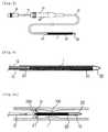
- A separate stent inserting device is required in the stent-used treatment method in order to insert the stent into the stenosal portion of tubular organs. One example of conventional stent inserting devices is shown in
Fig. 1 . Referring toFig. 1 , the stent inserting device includes a grip body 2, anexternal tube 3 connected to the grip body 2 and aninternal tube 5 inserted into theexternal tube 3 for movement in a forward or backward direction. A self-expandable stent 1 is slidably held within a tip end portion of theexternal tube 3 in a compressed state. Thestent 1 is pushed out of theexternal tube 3 by means of theinternal tube 5. - In the stent inserting device configured as above, the tip end portion of the
external tube 3 in which thestent 1 is fitted in a compressed state is inserted into the stenosal portion of tubular organs of a living body such as an esophagus and the like. At this time, an endoscope is separately inserted to allow an operator to bring the tip end portion of theexternal tube 3 into a target position, i.e., in the stenosal portion of tubular organs, while observing the stent. - Once the tip end portion of the
external tube 3 is inserted into the target position, theinternal tube 5 is slidingly moved forward to push thestent 1 out of the tip end portion of theexternal tube 3. As illustrated inFig. 2A , the leadingend 1a of thestent 1 is first pushed out of theexternal tube 3 and expanded back to its original shape. In other words, the conventional stent inserting device is designed to ensure that thestent 1 is first expanded at its leadingend 1a and then gradually expanded toward itstrailing end 1b. When completely pushed out of theexternal tube 3, thestent 1 is capable of expanding the stenosal portion as shown inFig. 2B . - In case a vocal cord or other membranes is situated behind the trailing
end 1b of thestent 1, the conventional stent inserting device suffers from a problem in that thetrailing end 1b of thestent 1 is caught by the vocal cord or other membranes in the process of expanding thestent 1 sequentially from the leading end toward the trailing end, which may cause thestent 1 to be situated in a wrong posture. - In particular, it is difficult to accurately estimate the position in which the
trailing end 1b of thestent 1 lies when thestent 1 is fully expanded over the entire length thereof. This is because there is a great difference between the stent length available when thestent 1 is held within the tip end of theexternal tube 3 in a compressed state and the stent length available when thestent 1 is expanded back to its original shape in the stenosal portion. - Such problems posed in situating the
stent 1 make it difficult for an operator to perform the stent inserting operation and also inflict physical or metal pains on a patient. In the worst circumstances, the stent inserting operation needs to be performed once again from the beginning. US2003/0163155 A1 discloses an introducer which deploys an endoluminal device in a distal location from a proximal location. The introducer comprises a retrograde portion, an anterograde portion axially moveable relative to the retrograde portion, a shaft having a distal tip and an anterograde sheath attached to the distal tip, and anchoring means in at least one of the retrograde portion or the anterograde portion for anchoring the device during deployment from its proximal end to its distal end. An inner sheath may be mounted concentrically over the shaft with the endoluminal device mounted concentrically over the inner sheath. The anchoring device may comprise an inflatable balloon mounted radially inside the retrograde portion, a tether, or an extended portion of the endoluminal device confined by a notch in the interface of two sheaths in the retrograde portion of the introducer, or may comprise a holder in the anterograde portion.- In view of the above-noted and other problems inherent in the prior art, it is an object of the present invention to provide a stent inserting device that can allow a stent to be first expanded at its trailing end and then gradually expanded toward its leading end within a stenosal portion of tubular organs and, therefore, can be effectively used in treating the stenosal portion where the position of a trailing end of the stent needs to be controlled accurately.
- Another object of the present invention is to provide a stent inserting device capable of easily and accurately situating a trailing end of a stent in a target stenosal portion of tubular organs of a living body without inflicting a physical or mental pain on a patient.
- The present invention is defined in the attached independent claim to which reference should now be made. Further, preferred features may be found in the sub-claims appended thereto.
- In accordance with one example, there is provided a stent inserting device for use in inserting a self-expandable stent with leading and trailing ends into a tubular organ of a living body, comprising: a grip body; an elongated flexible external tube attached to a front end of the grip body; an elongated flexible push member movably inserted into the external tube from a rear end of the grip body; and a tubular cap for removably receiving the stent in a compressed state, the tubular cap having a front end operatively connected to the push member and a rear end slidably fitted to a front end of the external tube, wherein the stent inserting device is designed to hold the stent within the tubular cap in such a manner that the stent is first expanded at the trailing end and then gradually expanded toward the leading end when the tubular cap is pushed away from the front end of the external tube by means of the push member.
- In accordance with an aspect of the present invention, there is provided a stent inserting device for use in inserting a self-expandable stent having a leading end and a trailing end, the device comprising:
- a grip body;
- an elongate flexible external tube attached to the grip body;
- an elongate flexible push member slidably received in the external tube; and
- a tubular cap for slidably receiving a given stent in a non-expanded state, the cap being configured for mounting at a leading end of the external tube for sliding movement, actuated by means of the push member, away from the leading end of the external tube to progressively unsheath said stent at or near its trailing end towards its leading end, such that self expansion of the stent first occurs at or near the trailing end of the stent and gradually towards the leading end of the stent.
- The stent inserting device comprises a movable internal tube positioned between the external tube and the push member for movement toward and away from the tubular cap.
- The push.member may be configured to extend into the tubular cap and is fixedly secured to the front end of the tubular cap.
- The above and other objects and features of the present invention will become apparent from the following description of preferred embodiments, given in conjunction with the accompanying drawings, in which:
Fig. 1 is a view showing one example of conventional stent inserting devices;Figs. 2A and 2B are section views illustrating a process of situating a stent in a stenosal portion by use of the conventional stent inserting device shown inFig. 1 ;Fig. 3 is a view showing a stent inserting device in accordance with an example not forming part of the present invention;Fig. 4 is an enlarged section view illustrating major parts of the stent inserting device shown inFig. 3 ;Figs. 5A and5B are section views illustrating a process of situating a stent in a stenosal portion by use of the stent inserting device shown inFig. 3 ;Fig. 6 is a view showing a stent inserting device in accordance with an embodiment of the present invention;Fig. 7 is an enlarged section view illustrating major parts of the stent inserting device shown inFig. 6 ; andFigs. 8A, 8B and 8C are section views illustrating a process of situating a stent in a stenosal portion by use of the stent inserting device shown inFig. 6 .- Preferred embodiments of a stent inserting device in accordance with the present invention will now be described in detail with reference to the accompanying drawings.
- Referring to
Figs. 3 and 4 , there is shown a stent inserting device in accordance with an example not forming parts of the present invention, which is used in inserting a self-expandable stent 1 with leading and trailing ends into a tubular organ of a living body. The stent inserting device of the present example includes agrip body 10, an elongated flexibleexternal tube 12 attached to a front end of thegrip body 10, an elongatedflexible push member 15 movably inserted into theexternal tube 12 from a rear end of thegrip body 10 and atubular cap 20 for removably receiving thestent 1 in a compressed state, thetubular cap 20 having afront end 22 operatively connected to thepush member 15 and arear end 21 slidably fitted to a front end of theexternal tube 12. - The stent inserting device of the present example is designed to hold the
stent 1 within thetubular cap 20 in such a manner that thestent 1 is first expanded at the trailing end and then gradually expanded toward the leading end when thetubular cap 20 is pushed away from the front end of theexternal tube 12 by means of thepush member 15. - The
front end 22 of thetubular cap 20 is formed into a round shape so that it can assist in smoothly inserting thetubular cap 20 into the tubular organ of the living body. Thepush member 15 is configured to extend into thetubular cap 20 and is fixedly secured to thefront end 22 of thetubular cap 20. Ahandle 16 is attached to a rear end of thepush member 15. - Next, description will be made on an operation of the stent inserting device configured as above.
- First, a
stent 1 having a suitable size is selected depending on the diameter and length of atarget lesion 100, e.g., a stenosal portion, present in a tubular organ of a living body. Then, thestent 1 is received within thetubular cap 20 in a compressed state. Therear end 21 of thetubular cap 20 is fitted to the front end of theexternal tube 12. - Once the preparation work is finished in this manner, the
external tube 12 is inserted into the tubular organ of the living body and situated in alignment with thetarget lesion 100 of the tubular organ, e.g., a blood vessel. The stent insertion operation is visually monitored by use of an endoscope which is inserted into the tubular organ in parallel with theexternal tube 12. At this time, therear end 21 of thetubular cap 20, more precisely, the trailingend 1b of thestent 1 is situated in alignment with the rear end of thetarget lesion 100. - In this state, if the
push member 15 is pushed forward while holding thegrip body 10, thetubular cap 20 connected to the front end of thepush member 15 is caused to move forward away from theexternal tube 12. Thus, thestent 1 is expanded at the trailingend 1b thereof as illustrated inFig. 5A . As thetubular cap 20 continues to move forward, thestent 1 is gradually expanded toward theleading end 1a thereof and, at last, fully expanded over the entire length as illustrated inFig. 5B . When fully expanded, thestent 1 is returned back to its original shape, thereby expanding thetarget lesion 100, i.e., the stenosal portion of the tubular organ. - After the
stent 1 has been situated in thetarget lesion 100, thepush member 15 is pulled backward so that thetubular cap 20 can be moved backward through thestent 1. Then, theexternal tube 12 is removed from the tubular organ of the living body together with thetubular cap 20. - With the stent inserting device of the present example as described above, the
stent 1 is first expanded at the trailingend 1b and then gradually expanded toward theleading end 1a within thetarget lesion 100, i.e., the stenosal portion of the tubular organ. Therefore, the stent inserting device can be effectively used in treating the stenosal portion of an esophagus or the like where the position of the trailingend 1b of thestent 1 must be controlled accurately to avoid interference with avocal cord 200 or other membranes situated behind the trailingend 1b of thestent 1. - Turning to
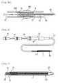
Figs. 6 and 7 , there is shown a stent inserting device in accordance with an embodiment of the present invention, which is used in inserting a self-expandable stent 1 with leading and trailing ends into a tubular organ of a living body. As in the previous example, the stent inserting device of the present embodiment includes agrip body 10, an elongated flexibleexternal tube 12 attached to a front end of thegrip body 10, an elongatedflexible push member 15 movably inserted into theexternal tube 12 from a rear end of thegrip body 10 and atubular cap 20 for removably receiving thestent 1 in a compressed state, thetubular cap 20 having afront end 22 operatively connected to thepush member 15 and arear end 21 slidably fitted to a front end of theexternal tube 12. - Unlike the previous example, the stent inserting device of the present embodiment further includes a movable
internal tube 30 positioned between theexternal tube 12 and thepush member 15 for movement toward and away from thetubular cap 20. An annular space for receiving the trailing end of thestent 1 is left between the front end of theinternal tube 30 and the front end of theexternal tube 12. - The stent inserting device of the present embodiment is designed to hold the
stent 1 within thetubular cap 20 and also within the front end of theexternal tube 12 in such a manner that thestent 1 is first expanded at a portion near the trailing end and then gradually expanded toward the trailing end and then the leading end when thetubular cap 20 is pushed away from the front end of theexternal tube 12 by means of thepush member 15. - The
front end 22 of thetubular cap 20 is formed into a round shape so that it can assist in smoothly inserting thetubular cap 20 into the tubular organ of the living body. Thepush member 15 is configured to extend into thetubular cap 20 and is fixedly secured to thefront end 22 of thetubular cap 20. Ahandle 16 is attached to a rear end of thepush member 15. - Next, description will be made on an operation of the stent inserting device configured as above.
- First, the
stent 1 is received within thetubular cap 20 in a compressed state so that the trailing end of thestent 1 can lie inside the front end of theexternal tube 12. Therear end 21 of thetubular cap 20 is fitted to the front end of theexternal tube 12. - Once the preparation work is finished in this manner, the
external tube 12 is inserted into the tubular organ of the living body and situated in alignment with thetarget lesion 100 of the tubular organ, e.g., a blood vessel. The stent insertion operation is visually monitored by use of an endoscope which is inserted into the tubular organ in parallel with theexternal tube 12. At this time, therear end 21 of thetubular cap 20, more precisely, the trailingend 1b of thestent 1 is situated in alignment with the rear end of thetarget lesion 100. - In this state, if the
push member 15 is pushed forward while holding thegrip body 10, thetubular cap 20 connected to the front end of thepush member 15 is caused to move forward away from theexternal tube 12. Thus, thestent 1 is expanded at a portion near the trailingend 1b thereof as illustrated inFig. 8A . At this moment, theinternal tube 30 is pushed forward so that the trailingend 1b of thestent 1 can be pushed out of theexternal tube 12 and expanded as illustrated inFig. 8B . - As the
tubular cap 20 continues to move forward, thestent 1 is gradually expanded toward theleading end 1a thereof and, at last, fully expanded over the entire length as illustrated inFig. 8C . When fully expanded, thestent 1 is returned back to its original shape, thereby expanding thetarget lesion 100, i.e., the stenosal portion of the tubular organ. - After the
stent 1 has been situated in thetarget lesion 100, thepush member 15 is pulled backward so that thetubular cap 20 can be moved backward through thestent 1. Then, theexternal tube 12 is removed from the tubular organ of the living body together with thetubular cap 20. - With the stent inserting device of the present embodiment as described above, the
stent 1 is first expanded at the trailingend 1b and then gradually expanded toward theleading end 1a within thetarget lesion 100, i.e., the stenosal portion of the tubular organ. Therefore, the stent inserting device can be effectively used in treating the stenosal portion of an esophagus or the like where the position of the trailingend 1b of thestent 1 must be controlled accurately to avoid interference with avocal cord 200 or other membranes situated behind the trailingend 1b of thestent 1. - As described hereinabove, the stent inserting device of the present invention can allow the stent to be first expanded at its trailing end and then gradually expanded toward its leading end within a stenosal portion of tubular organs and, therefore, can be effectively used in treating the stenosal portion where the position of a trailing end of the stent needs to be controlled accurately. Furthermore, the stent inserting device of the present invention is capable of easily and accurately situating the trailing end of the stent in the stenosal portion of tubular organs without inflicting a physical or mental pain on a patient.
- While certain embodiments of the present invention have been described hereinabove, the present invention is not limited to these embodiments. It will be understood by those skilled in the art that various changes and modifications may be made without departing from the scope of the invention defined in the claims.
Claims (2)
- A stent inserting device for use in inserting a self-expandable stent with leading and trailing ends into a tubular organ of a living body, comprising:a grip body (10);an elongated flexible external tube (12) attached to a front end (22) of the grip body (10);an elongated flexible push member (15) movably inserted into the external tube (12) from a rear end (21) of the grip body (10); anda tubular cap (20) for removably receiving the stent (1) in a compressed state, the tubular cap (20) having a front end (22) operatively connected to the push member (15) and a rear end (21) slidably fitted to a front end (22) of the external tube (12);characterized by further comprising:a movable internal tube (30) positioned between the external tube (12) and the push member (15) for movement towards and away from the grip body (10);wherein the stent inserting device is designed to hold the stent within the tubular cap (20) so that the trailing end of the stent (1) lies inside the front end of the external tube (12); andwherein in use the tubular cap (20) is pushed away from the front end (22) of the external tube (12) by means of the push member (15) in such a manner that the stent (1) is first expanded near the trailing end and then gradually expanded toward the leading end, and wherein the internal tube (30) is pushed forward relative to the grip body (10) so that the trailing end of the stent is pushed out of the external tube (12) and expanded.
- The stent inserting device as recited in claim 1, wherein the push member (15) is configured to extend into the tubular cap (20) and is fixedly secured to the front end (22) of the tubular cap (20).
Applications Claiming Priority (1)
| Application Number | Priority Date | Filing Date | Title |
|---|---|---|---|
| KR20070039377AKR100822045B1 (en) | 2007-04-23 | 2007-04-23 | Stent insertion device for body stenosis |
Publications (3)
| Publication Number | Publication Date |
|---|---|
| EP1985261A2 EP1985261A2 (en) | 2008-10-29 |
| EP1985261A3 EP1985261A3 (en) | 2009-10-21 |
| EP1985261B1true EP1985261B1 (en) | 2016-03-02 |
Family
ID=39534798
Family Applications (1)
| Application Number | Title | Priority Date | Filing Date |
|---|---|---|---|
| EP08251053.8AActiveEP1985261B1 (en) | 2007-04-23 | 2008-03-25 | Stent inserting device |
Country Status (5)
| Country | Link |
|---|---|
| US (1) | US8372132B2 (en) |
| EP (1) | EP1985261B1 (en) |
| JP (1) | JP4778974B2 (en) |
| KR (1) | KR100822045B1 (en) |
| CN (1) | CN101292917B (en) |
Families Citing this family (20)
| Publication number | Priority date | Publication date | Assignee | Title |
|---|---|---|---|---|
| US7018401B1 (en) | 1999-02-01 | 2006-03-28 | Board Of Regents, The University Of Texas System | Woven intravascular devices and methods for making the same and apparatus for delivery of the same |
| KR101659197B1 (en) | 2006-10-22 | 2016-09-22 | 이데브 테크놀로지스, 아이엔씨. | Devices and methods for stent advancement |
| MX2009004291A (en) | 2006-10-22 | 2009-09-07 | Idev Technologies Inc | Methods for securing strand ends and the resulting devices. |
| KR101109696B1 (en)* | 2009-01-22 | 2012-01-31 | 신경민 | Catheter structure for stent surgery |
| KR101041183B1 (en) | 2009-11-16 | 2011-06-13 | (주) 태웅메디칼 | Stent graft loading device |
| US9023095B2 (en) | 2010-05-27 | 2015-05-05 | Idev Technologies, Inc. | Stent delivery system with pusher assembly |
| US8864811B2 (en)* | 2010-06-08 | 2014-10-21 | Veniti, Inc. | Bi-directional stent delivery system |
| US20120172887A1 (en)* | 2011-01-05 | 2012-07-05 | Wilson-Cook Medical, Inc. d/b/a Cook Endoscopy | Proximal Release Expandable Prosthesis Delivery System |
| CN103142336B (en)* | 2013-03-29 | 2014-12-10 | 孙思予 | One-piece stent inserter |
| KR101514055B1 (en)* | 2013-12-17 | 2015-04-21 | 주식회사 스텐다드싸이텍 | Catheter for common hepatic duct |
| CN103989500B (en) | 2014-05-23 | 2015-11-18 | 南京微创医学科技有限公司 | A kind of hemostatic clamp |
| US10327933B2 (en)* | 2015-04-28 | 2019-06-25 | Cook Medical Technologies Llc | Medical cannulae, delivery systems and methods |
| JP6854282B2 (en)* | 2015-09-18 | 2021-04-07 | テルモ株式会社 | Pressable implant delivery system |
| US10660776B2 (en) | 2016-04-11 | 2020-05-26 | Boston Scientific Scimed, Inc. | Stent delivery system with collapsible loading frame |
| KR101709601B1 (en)* | 2016-05-30 | 2017-02-23 | 주식회사 에스앤지바이오텍 | Inserting Device of Stent Having Guide Member Having Fixing Part |
| KR101976743B1 (en) | 2017-07-14 | 2019-05-09 | 주식회사 비씨엠 | Stent insertion device for human digestive organ connection |
| KR102072677B1 (en)* | 2017-12-26 | 2020-02-03 | 연세대학교 산학협력단 | Equipment for stent graft loading |
| KR102489167B1 (en) | 2018-04-09 | 2023-01-17 | 보스톤 싸이엔티픽 싸이메드 인코포레이티드 | Stent delivery system with reduced deployment force |
| US11141297B2 (en) | 2018-12-19 | 2021-10-12 | Cook Medical Technologies Llc | Endovascular delivery device having an improved top-cap assembly |
| CN117815522A (en)* | 2024-03-06 | 2024-04-05 | 北京泰杰伟业科技股份有限公司 | Mechanical balloon device |
Citations (1)
| Publication number | Priority date | Publication date | Assignee | Title |
|---|---|---|---|---|
| US20040093061A1 (en)* | 2001-12-03 | 2004-05-13 | Xtent, Inc. A Delaware Corporation | Apparatus and methods for delivery of multiple distributed stents |
Family Cites Families (13)
| Publication number | Priority date | Publication date | Assignee | Title |
|---|---|---|---|---|
| US5683451A (en)* | 1994-06-08 | 1997-11-04 | Cardiovascular Concepts, Inc. | Apparatus and methods for deployment release of intraluminal prostheses |
| JP3583828B2 (en)* | 1995-03-15 | 2004-11-04 | テルモ株式会社 | Therapeutic device delivery catheter |
| US6077295A (en)* | 1996-07-15 | 2000-06-20 | Advanced Cardiovascular Systems, Inc. | Self-expanding stent delivery system |
| US6007573A (en)* | 1996-09-18 | 1999-12-28 | Microtherapeutics, Inc. | Intracranial stent and method of use |
| KR100341019B1 (en)* | 1999-08-18 | 2002-06-20 | 신경민 | The flexible self- expandable stent foundation device |
| US7887573B2 (en)* | 2002-02-22 | 2011-02-15 | Boston Scientific Scimed, Inc. | Method and apparatus for deployment of an endoluminal device |
| DE10219194B4 (en)* | 2002-04-29 | 2004-06-03 | Qualimed Innovative Medizinprodukte Gmbh | Instrument for implanting expandable cylindrical vascular prostheses |
| US7264632B2 (en)* | 2002-06-07 | 2007-09-04 | Medtronic Vascular, Inc. | Controlled deployment delivery system |
| KR100464501B1 (en)* | 2003-04-10 | 2005-01-03 | (주) 태웅메디칼 | Stent insertion device |
| US7553324B2 (en)* | 2003-10-14 | 2009-06-30 | Xtent, Inc. | Fixed stent delivery devices and methods |
| DE602005005567T2 (en)* | 2004-07-28 | 2009-04-30 | Cordis Corp., Miami Lakes | Insertion device with a low deployment force |
| CN2783951Y (en)* | 2005-02-01 | 2006-05-31 | 维科医疗器械(苏州)有限公司 | Self-expanding type bracket coaxial releasing system for reclaiming protective umbrella |
| KR100945431B1 (en)* | 2007-10-05 | 2010-03-05 | 한국원자력연구원 | Mass production type thin film deposition apparatus using multi-layer substrate holder |
- 2007
- 2007-04-23KRKR20070039377Apatent/KR100822045B1/enactiveActive
- 2008
- 2008-02-04JPJP2008023711Apatent/JP4778974B2/enactiveActive
- 2008-02-14USUS12/070,095patent/US8372132B2/enactiveActive
- 2008-02-25CNCN2008100093496Apatent/CN101292917B/enactiveActive
- 2008-03-25EPEP08251053.8Apatent/EP1985261B1/enactiveActive
Patent Citations (1)
| Publication number | Priority date | Publication date | Assignee | Title |
|---|---|---|---|---|
| US20040093061A1 (en)* | 2001-12-03 | 2004-05-13 | Xtent, Inc. A Delaware Corporation | Apparatus and methods for delivery of multiple distributed stents |
Also Published As
| Publication number | Publication date |
|---|---|
| EP1985261A3 (en) | 2009-10-21 |
| JP2008264502A (en) | 2008-11-06 |
| CN101292917A (en) | 2008-10-29 |
| US20080262591A1 (en) | 2008-10-23 |
| US8372132B2 (en) | 2013-02-12 |
| CN101292917B (en) | 2013-01-23 |
| JP4778974B2 (en) | 2011-09-21 |
| KR100822045B1 (en) | 2008-04-15 |
| EP1985261A2 (en) | 2008-10-29 |
Similar Documents
| Publication | Publication Date | Title |
|---|---|---|
| EP1985261B1 (en) | Stent inserting device | |
| EP1861156B1 (en) | Access catheter having dilation capability | |
| JP4284002B2 (en) | Stent delivery system to prevent twist and method of loading the same | |
| US5078720A (en) | Stent placement instrument and method | |
| US7785360B2 (en) | Instrument for implanting vascular prostheses | |
| US20070078504A1 (en) | Device for placing a vascular implant | |
| EP2421469B1 (en) | System for delivering and deploying an occluding device within a vessel | |
| CN102137644B (en) | Introducer for endovascular implants | |
| EP2227189B1 (en) | Deployment handle for an implant deployment device | |
| KR102345946B1 (en) | Apparatus and method for tissue retraction | |
| US20070173918A1 (en) | Apparatus and methods for locating an ostium of a vessel | |
| CA2845552C (en) | Distal capture device for a self-expanding stent | |
| US20060190069A1 (en) | Unidirectional delivery system | |
| EP2645945B1 (en) | Device for retrieving a body from a tubular structure | |
| WO2017017753A1 (en) | Tissue recovery tool and tissue recovery system | |
| JP2010057770A (en) | Catheter assembly | |
| KR101101768B1 (en) | Stent Insertion Device | |
| JP7216578B2 (en) | stent delivery system | |
| WO2022221734A1 (en) | Biopsy device | |
| HK1186367A (en) | Device for retrieving a body from a tubular structure | |
| HK1186367B (en) | Device for retrieving a body from a tubular structure |
Legal Events
| Date | Code | Title | Description |
|---|---|---|---|
| PUAI | Public reference made under article 153(3) epc to a published international application that has entered the european phase | Free format text:ORIGINAL CODE: 0009012 | |
| 17P | Request for examination filed | Effective date:20080331 | |
| AK | Designated contracting states | Kind code of ref document:A2 Designated state(s):AT BE BG CH CY CZ DE DK EE ES FI FR GB GR HR HU IE IS IT LI LT LU LV MC MT NL NO PL PT RO SE SI SK TR | |
| AX | Request for extension of the european patent | Extension state:AL BA MK RS | |
| PUAL | Search report despatched | Free format text:ORIGINAL CODE: 0009013 | |
| AK | Designated contracting states | Kind code of ref document:A3 Designated state(s):AT BE BG CH CY CZ DE DK EE ES FI FR GB GR HR HU IE IS IT LI LT LU LV MC MT NL NO PL PT RO SE SI SK TR | |
| AX | Request for extension of the european patent | Extension state:AL BA MK RS | |
| 17Q | First examination report despatched | Effective date:20100118 | |
| AKX | Designation fees paid | Designated state(s):DE FR GB IT | |
| REG | Reference to a national code | Ref country code:DE Ref legal event code:R079 Ref document number:602008042570 Country of ref document:DE Free format text:PREVIOUS MAIN CLASS: A61F0002840000 Ipc:A61F0002966000 | |
| GRAP | Despatch of communication of intention to grant a patent | Free format text:ORIGINAL CODE: EPIDOSNIGR1 | |
| RIC1 | Information provided on ipc code assigned before grant | Ipc:A61F 2/95 20130101ALN20150807BHEP Ipc:A61F 2/966 20130101AFI20150807BHEP | |
| INTG | Intention to grant announced | Effective date:20150825 | |
| GRAS | Grant fee paid | Free format text:ORIGINAL CODE: EPIDOSNIGR3 | |
| GRAA | (expected) grant | Free format text:ORIGINAL CODE: 0009210 | |
| AK | Designated contracting states | Kind code of ref document:B1 Designated state(s):DE FR GB IT | |
| REG | Reference to a national code | Ref country code:GB Ref legal event code:FG4D | |
| REG | Reference to a national code | Ref country code:DE Ref legal event code:R096 Ref document number:602008042570 Country of ref document:DE | |
| REG | Reference to a national code | Ref country code:FR Ref legal event code:PLFP Year of fee payment:9 | |
| REG | Reference to a national code | Ref country code:DE Ref legal event code:R097 Ref document number:602008042570 Country of ref document:DE | |
| PLBE | No opposition filed within time limit | Free format text:ORIGINAL CODE: 0009261 | |
| STAA | Information on the status of an ep patent application or granted ep patent | Free format text:STATUS: NO OPPOSITION FILED WITHIN TIME LIMIT | |
| 26N | No opposition filed | Effective date:20161205 | |
| REG | Reference to a national code | Ref country code:FR Ref legal event code:PLFP Year of fee payment:10 | |
| REG | Reference to a national code | Ref country code:FR Ref legal event code:PLFP Year of fee payment:11 | |
| REG | Reference to a national code | Ref country code:DE Ref legal event code:R082 Ref document number:602008042570 Country of ref document:DE Representative=s name:HL KEMPNER PATENTANWAELTE, SOLICITORS (ENGLAND, DE Ref country code:DE Ref legal event code:R082 Ref document number:602008042570 Country of ref document:DE Representative=s name:HL KEMPNER PATENTANWALT, RECHTSANWALT, SOLICIT, DE Ref country code:DE Ref legal event code:R082 Ref document number:602008042570 Country of ref document:DE Representative=s name:HL KEMPNER PARTG MBB, DE | |
| REG | Reference to a national code | Ref country code:DE Ref legal event code:R081 Ref document number:602008042570 Country of ref document:DE Owner name:TAEWOONG MEDICAL CO., LTD., GIMPO-SI, KR Free format text:FORMER OWNER: TAEWOONG MEDICAL CO., LTD., KIMPO, KYONGGI, KR | |
| REG | Reference to a national code | Ref country code:GB Ref legal event code:732E Free format text:REGISTERED BETWEEN 20230901 AND 20230906 | |
| PGFP | Annual fee paid to national office [announced via postgrant information from national office to epo] | Ref country code:DE Payment date:20240319 Year of fee payment:17 Ref country code:GB Payment date:20240320 Year of fee payment:17 | |
| PGFP | Annual fee paid to national office [announced via postgrant information from national office to epo] | Ref country code:IT Payment date:20240304 Year of fee payment:17 Ref country code:FR Payment date:20240313 Year of fee payment:17 |