EP1984696B1 - Motion capture device and associated method - Google Patents
Motion capture device and associated methodDownload PDFInfo
- Publication number
- EP1984696B1 EP1984696B1EP07726410AEP07726410AEP1984696B1EP 1984696 B1EP1984696 B1EP 1984696B1EP 07726410 AEP07726410 AEP 07726410AEP 07726410 AEP07726410 AEP 07726410AEP 1984696 B1EP1984696 B1EP 1984696B1
- Authority
- EP
- European Patent Office
- Prior art keywords
- segment
- rank
- vector
- reference frame
- measurement
- Prior art date
- Legal status (The legal status is an assumption and is not a legal conclusion. Google has not performed a legal analysis and makes no representation as to the accuracy of the status listed.)
- Not-in-force
Links
Images


Classifications
- A—HUMAN NECESSITIES
- A61—MEDICAL OR VETERINARY SCIENCE; HYGIENE
- A61B—DIAGNOSIS; SURGERY; IDENTIFICATION
- A61B5/00—Measuring for diagnostic purposes; Identification of persons
- A61B5/103—Measuring devices for testing the shape, pattern, colour, size or movement of the body or parts thereof, for diagnostic purposes
- G—PHYSICS
- G06—COMPUTING OR CALCULATING; COUNTING
- G06F—ELECTRIC DIGITAL DATA PROCESSING
- G06F3/00—Input arrangements for transferring data to be processed into a form capable of being handled by the computer; Output arrangements for transferring data from processing unit to output unit, e.g. interface arrangements
- G06F3/01—Input arrangements or combined input and output arrangements for interaction between user and computer
- G06F3/011—Arrangements for interaction with the human body, e.g. for user immersion in virtual reality
- A—HUMAN NECESSITIES
- A61—MEDICAL OR VETERINARY SCIENCE; HYGIENE
- A61B—DIAGNOSIS; SURGERY; IDENTIFICATION
- A61B2562/00—Details of sensors; Constructional details of sensor housings or probes; Accessories for sensors
- A61B2562/02—Details of sensors specially adapted for in-vivo measurements
- A61B2562/0219—Inertial sensors, e.g. accelerometers, gyroscopes, tilt switches
- A—HUMAN NECESSITIES
- A61—MEDICAL OR VETERINARY SCIENCE; HYGIENE
- A61B—DIAGNOSIS; SURGERY; IDENTIFICATION
- A61B2562/00—Details of sensors; Constructional details of sensor housings or probes; Accessories for sensors
- A61B2562/02—Details of sensors specially adapted for in-vivo measurements
- A61B2562/0223—Magnetic field sensors
- A—HUMAN NECESSITIES
- A61—MEDICAL OR VETERINARY SCIENCE; HYGIENE
- A61B—DIAGNOSIS; SURGERY; IDENTIFICATION
- A61B2562/00—Details of sensors; Constructional details of sensor housings or probes; Accessories for sensors
- A61B2562/02—Details of sensors specially adapted for in-vivo measurements
- A61B2562/0233—Special features of optical sensors or probes classified in A61B5/00
- A—HUMAN NECESSITIES
- A61—MEDICAL OR VETERINARY SCIENCE; HYGIENE
- A61B—DIAGNOSIS; SURGERY; IDENTIFICATION
- A61B2562/00—Details of sensors; Constructional details of sensor housings or probes; Accessories for sensors
- A61B2562/04—Arrangements of multiple sensors of the same type
- A—HUMAN NECESSITIES
- A61—MEDICAL OR VETERINARY SCIENCE; HYGIENE
- A61B—DIAGNOSIS; SURGERY; IDENTIFICATION
- A61B5/00—Measuring for diagnostic purposes; Identification of persons
- A61B5/103—Measuring devices for testing the shape, pattern, colour, size or movement of the body or parts thereof, for diagnostic purposes
- A61B5/11—Measuring movement of the entire body or parts thereof, e.g. head or hand tremor or mobility of a limb
- A—HUMAN NECESSITIES
- A61—MEDICAL OR VETERINARY SCIENCE; HYGIENE
- A61B—DIAGNOSIS; SURGERY; IDENTIFICATION
- A61B5/00—Measuring for diagnostic purposes; Identification of persons
- A61B5/45—For evaluating or diagnosing the musculoskeletal system or teeth
- A61B5/4528—Joints
Definitions
- the inventionrelates to a motion capture device and the associated motion capture method.
- the inventionalso relates to a motion reproduction device and the associated motion reproduction method.
- a motion capture device of a structureis a device that measures quantities able to describe, by processing, the movement of the structure.
- the structurecan be, for example, a person or a robot moving or not.
- a first category of motion capture devicesconsists of devices that comprise two distinct parts: a first part is placed on the moving object and a second part is fixed with respect to the movement of the object.
- this first categorywe distinguish mainly optical systems, electromagnetic systems and ultrasonic systems. These devices are efficient in terms of accuracy. However, they have a number of disadvantages. It is therefore necessary to install hardware both on the object and in the environment of the object. In any case, these systems have a reduced range (in relation to the range of the physical source) and a long installation and calibration phase. Their cost is also very high.
- Ultrasonic systemsas well as optical systems, find the positions of transmitters. Both technologies suffer from the same limitation in space as camera-based technology.
- a second category of devicesrelates to devices in one block disposed on the mobile. This is the case of exoskeleton devices. These devices make it possible to overcome the limitation of the capture volume but are constraining since they consist of mechanical articulated arms arranged on the structure or the person. Movement reconstruction uses angle and non-position measurements between articulated limb segments.
- the French patent application FR 2,838,185describes a device for capturing the orientation of a solid that moves in a reference frame.
- the motion capture deviceprovides, from measurements from axial or vector sensors placed on the solid, at least one orientation angle ⁇ that is made by the movable reference of the solid in the reference frame.
- the sensors usedare preferably a magnetometer and an accelerometer.
- the measurements M of the physical quantities which are carried out respectively by the accelerometer and the magnetometerare thus modeled as a function F which translates the rotation ⁇ of the attached marker to the solid relative to the fixed reference in which the solid evolves.
- the unknowns ⁇ and athen form a high dimensional space which practically prohibits an inversion of the function F. It is then not possible to extract the unknowns ⁇ and a from equation (3). Without additional information, the device therefore does not allow the measurement of orientation angles when the mobile is accelerated or, at least, since the acceleration of the mobile can not be neglected. This represents a disadvantage.
- the inventiondoes not have the disadvantages of the devices mentioned above.
- the second measuring means and the additional measuring meansconsist of an accelerometer and a sensor which delivers a measurement of a uniform physical field present in the space where the structure and direction known in the reference frame.
- the second measuring means and the additional measuring meansfurther comprise at least one gyrometric axis.
- the sensor that delivers a measurement of a uniform physical field of known direction in the reference frameis a magnetometer.
- the senor which delivers a measurement of a uniform physical field of known direction in the reference frameis a photocell.
- the first meansconsist of a speed meter so that the information able to restore an absolute acceleration vector of a point of the rank 1 segment is the speed of the point.
- the first meansconsist of a position meter so that the information able to restore an absolute acceleration vector of a point of the rank 1 segment is the position of the point.
- radio transmission meanstransmit elementary electrical signals representative of the measurements delivered by the first measurement means and the second measurement means to the calculation means.
- the radio transmission meanscomprise an intermediate unit which receives the elementary electrical signals and which re-transmits an electrical signal representative of the elementary electrical signals to the calculation means.
- storage meansmemorize the measurements delivered by the first measuring means and the second measuring means.
- the storage meansare placed on the structure.
- An elementary measuring deviceconsists of two types of sensors, at least one of which is an accelerometer.
- an elementary measurement deviceis produced using a solid rotation motion capture device such as that described in the French patent application published under the reference FR 2,838,185 and filed, on behalf of the Applicant, dated April 5, 2002.
- An elementary measurement deviceis thus constituted of a couple (accelerometer, X sensor).
- An X-ray sensoris any sensor that provides a measure of a uniform physical field present in the space in which the mobile is moving, a physical field whose direction is known in the reference frame or which is measured in a reference position.
- the only constraints concerning the X sensorare, on the one hand, that the sensor must not be sensitive to accelerations and, on the other hand, that the direction of the measured physical field is different from the vertical.
- the X sensorcan be a magnetometer that measures the direction of the Earth's magnetic field.
- the sensor Xcan also be a photocell whose measurement is that of the light intensity that arrives on the cell.
- the source of illuminationis the sun and we know the date, time, longitude and latitude when measuring the light intensity
- the X sensormay also consist of one or more gyrometric axes that complete the measurement of the accelerometer.
- the first means that deliver information capable of restoring an absolute acceleration vector at 1 of a point of the rank 1 segmentcan be realized by a system of local measurements.
- a simple accelerometeris not suitable if there is no means to compensate for the acceleration of gravity.
- the local measurement systemcan be advantageously placed in the center of mass or near the center of mass of the body of the person (belt, for example).
- the local measurement systemmay be, for example, a GPS (Global Positioning System) type device associated with a differentiator.
- GPSGlobal Positioning System
- the GPS devicemakes it possible to know at any moment the position of the element carrying it and a differentiator, by deriving twice the position data, determines the absolute acceleration in the geographical reference.
- the local measurement systemcan also be realized using a radio localization device associated with a differentiator.
- Radio localization devicesrequire the use of beacons (ULB (ULB for "Ultra Wide Band” radar, optical beacon, etc.) .
- the radio localization devicesthus lose the autonomous character of the local measurement system.
- ULBUniversal Broadband
- the use of radio systemsalso has the dual advantage of data transmission and position measurement (this is particularly the case ULB devices.) As in the case of the GPS device, the position measurement delivered by the radio locating device is derived twice to obtain the acceleration measurement.
- An oriented pressure measurement(tube) is directly correlated to the speed of a body in the air. It is thus possible to determine, along three axes, the velocity vector of a segment on which is fixed a pressure meter. By deriving once the speed measurement, we obtain the acceleration.
- the motion capture devicecan advantageously be "dynamic" at the level of the hierarchical structure of the moving structure.
- the local measurement system (s) MLcan (can) be placed (s) indifferently at the level of the foot, the hand, waist, etc., or any other part of the body comparable to a rigid element.
- the first means that deliver information capable of restoring an absolute acceleration vector at 1 of a point of the rank 1 segmentare not measuring means.
- This segmentcan then advantageously be chosen as being the rank 1 segment.
- the first means that deliver the information capable of restoring an absolute acceleration vector at 1 of a point of the rank 1 segmentcan then be, for example, storage means which have knowledge of the fixed position occupied by a point of the rank segment 1 in the reference frame.
- the first means which deliver information capable of restoring an absolute acceleration vector at 1are measuring means ML fixed on the rank segment 1.
- the measuring means MLwill be considered superimposed on the second measuring means MD 1 which are also fixed on the rank segment 1.
- the means ML and MD 1are distant from each other, the position of the measuring means ML then being comparable to a virtual point of articulation between the rank segment 1 and a zero rank virtual segment.
- An MD measuring devicecan characterize a state of rest. The variance of the signals delivered by the device MD is then less than a threshold. As soon as a rest state is detected at a point, there is a very high probability that this point is at rest in the fixed reference frame (indeed, although a uniform rectilinear motion gives the same result as a state of rest, such a movement is unlikely and difficult to maintain). In the case of a detected rest, the acceleration of the structure is zero and the state of rest can be detected.
- the method of the inventionapplies so that the rank segment 1 is, alternatively, the right foot or the left foot.
- the figure 1represents an example of articulated structure concerned by the motion capture device of the invention.
- the structurefor example a human body or a humanoid robot, is decomposed into a set of segments that are all solid elements articulated with respect to each other.
- the set of segmentsis thus broken down into a head segment TE, a neck segment C, a set of trunk segments T1, T2, T3, a set of left arm segments BG1, BG2, BG3, BG4, a set of right arm segments BD1, BD2, BD3, BD4, a set of left leg segments JG1, JG2, JG3, JG4, JG5 and a set of right leg segments JD1, JD2, JD3, JD4, JD5.
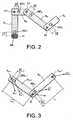
- the figure 2represents an articulated structure provided with a motion capture device according to the invention.
- the structureis, for example, a robot arm consisting of four articulated segments B 1 , B 2 , B 3 , B 4 from the shoulder to the hand.
- the segment B 1is provided with a local measurement system ML and a basic device for orientation measurements MD 1 .
- the elementary measurement device MD 1is remote from the local measurement system ML.
- the fixing point of the local measurement system ML and the fixing point of the elementary measuring device MD 1define a vector D 1 module D 1 and oriented from ML to MD1.
- the local measurement system MLis useless since it is then known that the acceleration of this point is zero in the reference frame.
- An elementary device of orientation measurements MD nis placed on each segment B n .
- the attachment point of the elementary measuring device MD nis distant from the point of articulation p n , the attachment point of the elementary measuring device MD n and the point of articulation p n defining a vector D n of module D n and oriented from p n to MD n .
- the motion reproducing device of the inventionhas the function of estimating, step by step, from the knowledge of the acceleration and orientation of the first segment B 1 , the acceleration of the articulation points. successive segments and the angles between the segments.
- nis the generic index, or rank, of a segment
- kis a generic index of incrementation of time
- nis the acceleration of the point of articulation p n of the segment of rank n in a fixed reference frame
- ⁇ nis the three-dimensional orientation (3D orientation) of the segment of rank n in the fixed reference frame.
- the accelerations a n and orientations ⁇ nare most often noted in scalar form in the patent application. It should be noted, however, that all these quantities are three dimensional vectors in the reference frame.
- the figure 3is a detail view of a moving structure equipped with a motion capture device of the invention.
- a segment S nis articulated with a segment S n-1 at a point of articulation p n .
- the length of the segment S nis assimilated to the distance L n which separates the point of articulation p n + 1 from the articulation point p n .
- the length of the segment S n-1is assimilated to the distance L n-1 which separates the point of articulation p n from the point of articulation p n-1 .
- the points of articulation p n-1 and p ndefine a vector The n oriented from p n-1 to p n and whose modulus is equal to the distance separating the points of articulation p n and p n-1 .
- the point of articulation p nhas an acceleration a n and the point of articulation p n-1 has an acceleration a n-1 .
- the measurement points of the devices MD n and MD n-1 on the respective segments of rank n and n-1have the respective acceleration b n and b n-1 .
- the inventionwill be presented, on the one hand, in the particular case where the vectors D n are negligible (the vectors D n are then considered null vectors) and, on the other hand, in the general case where the vectors D n are not considered negligible.
- Equation (5)is an equation known per se which corresponds to equation (2) mentioned above.
- the Figure 4Brepresents, in the general case, the essential steps of the method of processing measures implemented in the context of the invention.
- the not - 1 ⁇ + d ⁇ ⁇ ⁇ not dt ⁇ D ⁇ not + ⁇ ⁇ not ⁇ ⁇ ⁇ not ⁇ D ⁇ not or : b ⁇ notat ⁇ not + d ⁇ ⁇ ⁇ not dt ⁇ D ⁇ not + ⁇ ⁇ not ⁇ ⁇ ⁇ not ⁇ D ⁇ not
- the Figure 5Arepresents a detailed flowchart of an essential step of the measurement processing process represented in Figure 4A .
- the quantities a n-1 (t k-2 ) and M n-1 (t k-2 )are applied to an operator 2 which implements equation (5) and delivers the orientation ⁇ n-1 (t k-2 ).
- the quantities a n-1 (t k-1 ) and M n-1 (t k-1 )are applied to an operator 2 which implements equation (5) and delivers the orientation ⁇ n- 1 (t k-1 ).
- a n-1 (t k ), ⁇ n-1 (t k ) and d ( ⁇ n-1 (t k )) / dtare then applied to an operator 1 which implements equation (4) and delivers the magnitude a n (t k ).
- the calculated quantity a n (t k ) and the known measured measurement M n (t k )are then applied to an operator 2 which implements equation (5) and delivers the orientation variable ⁇ n (t k ) .
- the processing of the measurements acquired by the articulated motion capture device of the inventionleads to the determination, for each segment of the moving structure, of its acceleration at the point of articulation and its orientation in a reference frame. It is then possible to describe the movement of the structure, for example on a screen.
- FIG. 5Brepresents a detailed flowchart of an essential step of the measurement processing process represented in Figure 4B .
- the sizes at n ( t k ) and ⁇ n (t k ) relating to the segment of rank nare here also determined from the directions ⁇ n (t k-1 ) and ⁇ n (t k-2 ) calculated, for the segment n, at times t k-1 and t k-2 .
- n-1 (t k-2 ), ⁇ n-1 (t k-3 ), ⁇ n-1 (t k-4 ) and M n-1 (t k-2 )are then applied to a operator 2 which implements equation (6) and delivers the orientation ⁇ n-1 (t k-2 ).
- the quantities a n-1 (t k-1 ), ⁇ n-1 (t k-2 ), ⁇ n- 1 (t k-3 ) and M n-1 (t k-1 )are applied to an operator 2 which implements equation (6) and delivers the orientation ⁇ n-1 (t k-1 ).
- the operator 2then delivers the orientation quantity ⁇ n (t k ).
- the processing of the measurements acquired by the articulated motion capture device of the inventionleads to the determination, for each segment of the moving structure, of its acceleration at the point of articulation and its orientation in a reference frame. It is then possible to describe the movement of the structure, for example on a screen.
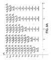
- the Figure 6Aillustrates, symbolically, in the particular case where the vectors D n are considered null, the evolution over time acceleration and orientation data obtained for the different segments of a structure with five articulated segments
- the horizontal axisrepresents the rank n of the segments that make up the structure and the vertical axis represents successive moments of measurement t k .
- the magnitudesacceleration and orientation
- These quantitiesconsist of measurement data and / or data derived from measurement data.
- the only known quantities relating to the segmentsare as follows: at 1 t 1 , ⁇ 1 t 1 .
- the known quantities relating to the segments of ranks 1 to 5are as follows: at 1 t 2 , ⁇ 1 t 2 , d ⁇ ⁇ 1 / dt t 2 .
- the Figure 6Billustrates, in the general case, the results of calculations of the acceleration and orientation data obtained, step by step, for the different segments of an articulated segment structure. Calculation of the acceleration and orientation data is described below for the first three segments.
- the measurements a 1 (t k ) and M 1 (t k )are used which respectively correspond to the measured (or calculated) acceleration on the segment 1 (thanks to the first measurement means ML) and the measurements delivered by the second measuring means (MD1).
- the measured (or calculated) acceleration on the segment 1is used at 1 (t k ), as are the orientations of the first segment ⁇ 1 (t k ) calculated at the previous step and ⁇ 1 (t k-1 ) and ⁇ 1 (t k-2 ) those given (or calculated) for the previous instants (t k-1 and t k-2 ).
- the acceleration a 2 (t k ) at the joint p2is calculated.
- a 2 (t k ) calculated in the previous stepis used, the measurements M 2 (t k ) of the measurement means MD 2 of the second segment at the instant t k .
- a 2is used (t k) the acceleration calculated at the second step of the first segment and the second segment of the directions ⁇ 2 (t k) calculated in the previous step and ⁇ 2 (t k -1 ) and ⁇ 2 (t k-2 ) data (or calculated) for the previous instants t k-1 and t k-2 .
- the acceleration a 3 (t k ) at the joint p3is calculated.
- the Figures 7A and 7Brepresent two embodiments of a motion reproduction device according to the invention.
- the structure S constituted of n articulated segmentsis represented symbolically by a rectangle.
- MD devices i and j ML systemsare distributed over the structure as has been previously described.
- m local measurement systemsare represented on the Figures 7A and 7B only one local measurement system suffices to implement the invention.
- the measurements delivered by the devices MD i and the measurements delivered by the local measurement systems ML jare transmitted, by the respective radio signals RD i and RL j , to a computing system 3, for example a computer.
- the motion reproduction devicethen comprises radio transmission means.
- the calculation system 3is provided with a reception antenna R which receives the signals RD i and RL j .
- the calculation system 3also receives, as input parameters, the value G of the local gravitational field in the reference frame, the value H of the local magnetic field in the reference frame, and the coordinates of the various vectors.
- the calculation system 3then implements data processing in accordance with what has been described above with reference to the figures 5 and 6 .
- a display device Efor example a screen, enables then to visualize the movement of the articulated structure.
- the Figure 7Bdiffers from the Figure 7A in that the radio signals RD i and RL j are not directly transmitted here to the calculation system 3 but are transmitted to an intermediate unit DEM fixed on the structure S.
- the unit DEMthen transmits the data it receives under the form of an RF radio signal to the computing system 3.
- an intermediate unit DEMon the structure S advantageously makes it possible to implement another embodiment of the invention. Indeed, in the case where the structure S moves at a great distance from the computing system 3, it is possible that the range of the RF signal is deteriorating.
- a memory card placed in the intermediate unit DEMcan then record the signals RD i and RL j .
- the data processingcan then be performed after the capture of the measurements, once the movement is executed, from the reading of the data recorded on the memory card.
Landscapes
- Health & Medical Sciences (AREA)
- Engineering & Computer Science (AREA)
- Life Sciences & Earth Sciences (AREA)
- Physics & Mathematics (AREA)
- Theoretical Computer Science (AREA)
- General Engineering & Computer Science (AREA)
- Veterinary Medicine (AREA)
- Pathology (AREA)
- Biomedical Technology (AREA)
- Heart & Thoracic Surgery (AREA)
- Medical Informatics (AREA)
- Molecular Biology (AREA)
- Surgery (AREA)
- Animal Behavior & Ethology (AREA)
- General Health & Medical Sciences (AREA)
- Public Health (AREA)
- Biophysics (AREA)
- Oral & Maxillofacial Surgery (AREA)
- Dentistry (AREA)
- General Physics & Mathematics (AREA)
- Human Computer Interaction (AREA)
- Physiology (AREA)
- Orthopedic Medicine & Surgery (AREA)
- Rheumatology (AREA)
- Measurement Of The Respiration, Hearing Ability, Form, And Blood Characteristics Of Living Organisms (AREA)
- Length Measuring Devices With Unspecified Measuring Means (AREA)
- Processing Or Creating Images (AREA)
- Burglar Alarm Systems (AREA)
- Die Bonding (AREA)
- Magnetic Resonance Imaging Apparatus (AREA)
- Telephone Function (AREA)
- Vending Machines For Individual Products (AREA)
- Vehicle Body Suspensions (AREA)
- Image Analysis (AREA)
Abstract
Description
Translated fromFrenchL'invention concerne un dispositif de capture de mouvement et le procédé de capture de mouvement associé. L'invention concerne également un dispositif de reproduction de mouvement et le procédé de reproduction de mouvement associé.The invention relates to a motion capture device and the associated motion capture method. The invention also relates to a motion reproduction device and the associated motion reproduction method.
Un dispositif de capture de mouvement d'une structure est un dispositif qui mesure des grandeurs aptes à décrire, par traitement, le mouvement de la structure. La structure peut être, par exemple, une personne ou un robot en déplacement ou non.A motion capture device of a structure is a device that measures quantities able to describe, by processing, the movement of the structure. The structure can be, for example, a person or a robot moving or not.
La capture du mouvement humain est une technique très utilisée dans de nombreuses applications: analyse biomécanique, télémanipulation, animation de personnage, ergonomie, etc.The capture of human motion is a technique widely used in many applications: biomechanical analysis, remote handling, character animation, ergonomics, etc.
Une première catégorie de dispositifs de capture de mouvement est constituée de dispositifs qui comprennent deux parties distinctes : une première partie est placée sur l'objet en mouvement et une deuxième partie est fixe par rapport au mouvement de l'objet. Dans cette première catégorie, on distingue principalement les systèmes optiques, les systèmes électromagnétiques et les systèmes à ultrasons. Ces dispositifs sont performants en termes de précision. Ils présentent toutefois un certain nombre d'inconvénients. Il est ainsi nécessaire d'installer du matériel à la fois sur l'objet et dans l'environnement de l'objet. Dans tous les cas, ces systèmes ont une portée réduite (en rapport à la portée de la source physique) et une phase d'installation et de calibration assez longue. Leur coût est également très élevé.A first category of motion capture devices consists of devices that comprise two distinct parts: a first part is placed on the moving object and a second part is fixed with respect to the movement of the object. In this first category, we distinguish mainly optical systems, electromagnetic systems and ultrasonic systems. These devices are efficient in terms of accuracy. However, they have a number of disadvantages. It is therefore necessary to install hardware both on the object and in the environment of the object. In any case, these systems have a reduced range (in relation to the range of the physical source) and a long installation and calibration phase. Their cost is also very high.
La technologie probablement la plus utilisée à l'heure actuelle est basée sur l'optique, comme cela est décrit, par exemple, dans les demandes de brevet
Les systèmes basés sur l'électromagnétisme reconstruisent les angles et les positions des capteurs disposés sur l'objet.Systems based on electromagnetism reconstruct the angles and positions of the sensors arranged on the object.
Les systèmes à ultrasons, de même que les systèmes optiques, retrouvent les positions des émetteurs. Ces deux technologies souffrent de la même limitation dans l'espace que la technologie à base de caméra.Ultrasonic systems, as well as optical systems, find the positions of transmitters. Both technologies suffer from the same limitation in space as camera-based technology.
Une seconde catégorie de dispositifs concerne des dispositifs en un seul bloc disposé sur le mobile. C'est le cas des dispositifs exosquelette. Ces dispositifs permettent de s'affranchir de la limitation du volume de capture mais sont contraignants puisqu'ils sont constitués de bras articulés mécaniques disposés sur la structure ou la personne. La reconstruction du mouvement utilise des mesures d'angle et non de position entre les segments des membres articulés.A second category of devices relates to devices in one block disposed on the mobile. This is the case of exoskeleton devices. These devices make it possible to overcome the limitation of the capture volume but are constraining since they consist of mechanical articulated arms arranged on the structure or the person. Movement reconstruction uses angle and non-position measurements between articulated limb segments.
Plus récemment, des systèmes basés sur un principe assez ancien (le principe des centrales inertielles) ont vu le jour à des échelles plus petites que les échelles traditionnelles, typiquement de quelques centimètres de côté (cf. le brevet
Une autre approche (cf. le brevet
La demande de brevet français
Les mesures M des grandeurs physiques qui sont effectuées respectivement par l'accéléromètre et par le magnétomètre sont ainsi modélisées comme une fonction F qui traduit la rotation θ du repère attaché au solide par rapport au repère fixe dans lequel évolue le solide.The measurements M of the physical quantities which are carried out respectively by the accelerometer and the magnetometer are thus modeled as a function F which translates the rotation θ of the attached marker to the solid relative to the fixed reference in which the solid evolves.
L'angle d'orientation θ est déduit de l'équation (1) par l'équation (2) suivante :
Si le mouvement est accéléré, une nouvelle équation (3) décrit le système, à savoir :
Les inconnues θ et a forment alors un espace de dimension élevée qui interdit, de façon pratique, une inversion de la fonction F. Il n'est alors pas possible d'extraire les inconnues θ et a de l'équation (3). Sans information supplémentaire, le dispositif ne permet donc pas la mesure des angles d'orientation dès lors que le mobile est accéléré ou, du moins, dès lors que l'accélération du mobile ne peut pas être négligée. Ceci représente un inconvénient.The unknowns θ and a then form a high dimensional space which practically prohibits an inversion of the function F. It is then not possible to extract the unknowns θ and a from equation (3). Without additional information, the device therefore does not allow the measurement of orientation angles when the mobile is accelerated or, at least, since the acceleration of the mobile can not be neglected. This represents a disadvantage.
L'invention ne présente pas les inconvénients des dispositifs mentionnés ci-dessus.The invention does not have the disadvantages of the devices mentioned above.
En effet, l'invention concerne un dispositif de capture de mouvement d'une structure constituée de N segments solides successifs articulés les uns par rapport aux autres à partir d'un segment de rang 1 jusqu'à un segment de rang N, N étant un nombre entier supérieur ou égal à 2, le segment de rang n (n = 2, ..., N) étant articulé avec le segment de rang n-1 au niveau d'un point d'articulation pn,caractérisé en ce qu'il comprend :
- des premiers moyens qui délivrent une information apte à restituer un vecteur d'accélération absolue
a 1 d'un point du segment derang 1 dans un repère de référence, à des instants successifs tk, k étant un nombre entier supérieur ou égal à 1, - des seconds moyens de mesure fixés sur le segment de
rang 1 et qui délivrent, à chaque instant tk, une mesure représentative d'un vecteur orientationΘ 1 du segment derang 1 dans le repère de référence, et - des moyens de mesure supplémentaires fixés sur chaque segment de rang n (n = 2, ..., N) et qui délivrent, à chaque instant tk, une mesure représentative d'un vecteur orientation
Θ n du segment de rang n.
- first means which deliver information capable of restoring an absolute acceleration vector
at 1 of a point of therow 1 segment in a reference frame, at successive instants tk , where k is an integer greater than or equal to 1, - second measuring means fixed on the
row 1 segment and delivering, at each instant tk , a measurement representative of an orientation vectorΘ 1 of therank 1 segment in the reference frame, and - additional measurement means fixed on each segment of rank n (n = 2, ..., N) and which deliver, at each instant tk , a measurement representative of an orientation vector
Θ n of the segment of rank n.
Selon une caractéristique supplémentaire de l'invention, les seconds moyens de mesure et les moyens de mesure supplémentaires sont constitués d'un accéléromètre et d'un capteur qui délivre une mesure d'un champ physique uniforme présent dans l'espace où se meut la structure et de direction connue dans le repère de référence.According to a further feature of the invention, the second measuring means and the additional measuring means consist of an accelerometer and a sensor which delivers a measurement of a uniform physical field present in the space where the structure and direction known in the reference frame.
Selon une autre caractéristique supplémentaire de l'invention, les seconds moyens de mesure et les moyens de mesure supplémentaires comprennent, en outre, au moins un axe gyrométrique.According to another additional feature of the invention, the second measuring means and the additional measuring means further comprise at least one gyrometric axis.
Selon encore une autre caractéristique supplémentaire de l'invention, le capteur qui délivre une mesure d'un champ physique uniforme de direction connue dans le repère de référence est un magnétomètre.According to yet another additional characteristic of the invention, the sensor that delivers a measurement of a uniform physical field of known direction in the reference frame is a magnetometer.
Selon encore une autre caractéristique supplémentaire de l'invention, le capteur qui délivre une mesure d'un champ physique uniforme de direction connue dans le repère de référence est une cellule photoélectrique.According to yet another additional characteristic of the invention, the sensor which delivers a measurement of a uniform physical field of known direction in the reference frame is a photocell.
Selon encore une autre caractéristique supplémentaire de l'invention, les premiers moyens sont constitués d'un mesureur de vitesse de sorte que l'information apte à restituer un vecteur d'accélération absolue d'un point du segment de rang 1 est la vitesse du point.According to yet another additional feature of the invention, the first means consist of a speed meter so that the information able to restore an absolute acceleration vector of a point of the
Selon encore une autre caractéristique supplémentaire de l'invention, les premiers moyens sont constitués d'un mesureur de position de sorte que l'information apte à restituer un vecteur d'accélération absolue d'un point du segment de rang 1 est la position du point.According to yet another additional characteristic of the invention, the first means consist of a position meter so that the information able to restore an absolute acceleration vector of a point of the
L'invention concerne également un dispositif de reproduction de mouvement d'une structure constituée de N segments solides successifs articulés les uns par rapport aux autres à partir d'un segment de rang 1 jusqu'à un segment de rang N, N étant un nombre entier supérieur ou égal à 2, le segment de rang n (n = 2, ..., N) étant articulé avec le segment de rang n-1 au niveau d'un point d'articulation pn,caractérisé en ce qu'il comprend :
- un dispositif de capture de mouvement selon l'invention dans lequel les moyens de mesure supplémentaires d'un segment de rang n sont positionnés à proximité du point d'articulation pn de telle sorte que la distance qui sépare les moyens de mesure supplémentaire d'un segment de rang n du point d'articulation pn est considérée comme nulle, et
- des moyens de calcul qui calculent, à chaque instant tk :
- a) le vecteur d'accélération absolue
a 1 dans le repère de référence, à partir de l'information délivrée par les premiers moyens, - b) le vecteur d'orientation
Θ 1 du segment derang 1 dans le repère de référence, à partir du vecteur d'accélération absoluea 1 et de la mesure représentative du vecteur orientationΘ 1 du segment derang 1 ; - c) un vecteur d'accélération
a n (n ≥ 2) du point d'articulation pn dans le repère de référence, à partir de l'équation :
oùω n = d(Θ n)/dt etL n étant un vecteur orienté du point d'articulation pn-1 vers le point d'articulation pn et dont le module a pour valeur la distance qui sépare le point d'articulation pn du point d'articulation pn-1; et - d) le vecteur d'orientation
Θ n (n ≥ 2) du segment de rang n à partir du vecteur d'accélérationa n et de la mesure représentative de l'orientation du segment de rang n.
- a) le vecteur d'accélération absolue

- a motion capture device according to the invention in which the additional measuring means of a segment of rank n are positioned near the point of articulation pn so that the distance between the additional measuring means and a segment of rank n of the articulation point pn is considered as zero, and
- calculating means which calculate, at each instant tk :
- a) the absolute acceleration vector
at 1 in the reference frame, from the information delivered by the first means, - b) the orientation vector
Θ 1 of therank 1 segment in the reference frame, from the absolute acceleration vectorat 1 and the representative measurement of the orientation vectorΘ 1 of therank 1 segment; - c) an acceleration vector
at n (n ≥ 2) of the point of articulation pn in the reference frame, starting from the equation:
orω n = d (Θ n ) / dt andThe n being an oriented vector of the point of articulation pn-1 towards the point of articulation pn and whose modulus has for value the distance separating the point of articulation pn from the point of articulation pn-1 ; and - d) the orientation vector
Θ n (n ≥ 2) of the n-rank segment from the acceleration vectorat n and the measure representative of the orientation of the segment of rank n.
- a) the absolute acceleration vector
L'invention concerne également un dispositif de reproduction de mouvement d'une structure constituée de N segments solides successifs articulés les uns par rapport aux autres à partir d'un segment de rang 1 jusqu'à un segment de rang N, N étant un nombre entier supérieur ou égal à 2, le segment de rang n (n = 2, ..., N) étant articulé avec le segment de rang n-1 au niveau d'un point d'articulation pn,caractérisé en ce qu'il comprend :
- un dispositif de capture de mouvement selon l'invention dans lequel les moyens de mesure supplémentaires d'un segment de rang n sont distants du point d'articulation pn, et
- des moyens de calcul qui calculent, à chaque instant tk :
- a) le vecteur d'accélération absolue
a 1 dans le repère de référence, à partir de l'information délivrée par les premiers moyens, - b) le vecteur d'orientation
Θ 1 du segment de rang 1 dans le repère de référence, à partir du vecteur d'accélération absoluea 1 et de la mesure représentative du vecteur orientationΘ 1 du segment de rang 1 ; - c) un vecteur d'accélération
a n (n ≥ 2) du point d'articulation pn dans le repère de référence, à partir de l'équation :
oùω n = d(Θ n)/dt,L n étant un vecteur orienté du point d'articulation pn-1 vers le point d'articulation pn et dont le module a pour valeur la distance qui sépare le point d'articulation pn du point d'articulation pn-1; et - d) le vecteur d'orientation
Θ n (n ≥ 2) et un vecteur d'accélérationb n du point de mesure des moyens de mesure supplémentaire fixés sur le segment de rang n à partir du vecteur d'accélérationa n, de la mesure représentative (Mn) de l'orientation du segment de rang n, et des vecteurs d'orientation du segment de rang n à au moins deux instants qui précèdent l'instant tk, avecb n tel que :
- a) le vecteur d'accélération absolue


- a motion capture device according to the invention in which the additional measuring means of a segment of rank n are distant from the articulation point pn , and
- calculating means which calculate, at each instant tk :
- a) the absolute acceleration vector
at 1 in the reference frame, from the information delivered by the first means, - b) the orientation vector
Θ 1 of therank 1 segment in the reference frame, from the absolute acceleration vectorat 1 and the representative measurement of the orientation vectorΘ 1 of therank 1 segment; - c) an acceleration vector
at n (n ≥ 2) of the point of articulation pn in the reference frame, starting from the equation:
orω n = d (Θ n ) / dt,The n being an oriented vector of the point of articulation pn-1 towards the point of articulation pn and whose modulus has for value the distance separating the point of articulation pn from the point of articulation pn-1 ; and - d) the orientation vector
Θ n (n ≥ 2) and an acceleration vectorb n of the measuring point additional measuring means fixed on the n-rank segment from the acceleration vectorat n , of the representative measurement (Mn ) of the orientation of the segment of rank n, and of the orientation vectors of the segment of rank n to at least two instants which precede the instant tk , withb n such that:
- a) the absolute acceleration vector
Selon une caractéristique supplémentaire de l'invention, des moyens de transmission radioélectrique transmettent des signaux électriques élémentaires représentatifs des mesures délivrées par les premiers moyens de mesure et les seconds moyens de mesure vers les moyens de calcul.According to a further feature of the invention, radio transmission means transmit elementary electrical signals representative of the measurements delivered by the first measurement means and the second measurement means to the calculation means.
Selon encore une caractéristique supplémentaire de l'invention, les moyens de transmission radioélectrique comprennent une unité intermédiaire qui reçoit les signaux électriques élémentaires et qui réémet un signal électrique représentatif des signaux électriques élémentaires vers les moyens de calcul.According to yet another characteristic of the invention, the radio transmission means comprise an intermediate unit which receives the elementary electrical signals and which re-transmits an electrical signal representative of the elementary electrical signals to the calculation means.
Selon encore une caractéristique supplémentaire de l'invention, des moyens de mémorisation mémorisent les mesures délivrées par les premiers moyens de mesure et les seconds moyens de mesure.According to a further feature of the invention, storage means memorize the measurements delivered by the first measuring means and the second measuring means.
Selon encore une caractéristique supplémentaire de l'invention, les moyens de mémorisation sont placés sur la structure.According to yet another characteristic of the invention, the storage means are placed on the structure.
L'invention concerne également :
- un procédé de capture de mouvement conforme à la revendication indépendante 14,
- un procédé de reproduction de mouvement conforme à la revendication indépendante 18, et
- un procédé de reproduction de mouvement conforme à la revendication indépendante 19.
- a motion capture method according to
independent claim 14, - a motion reproduction method according to independent claim 18, and
- a motion reproduction method according to the independent claim 19.
Un dispositif élémentaire de mesures selon l'invention est constitué de deux types de capteurs dont au moins un est un accéléromètre.An elementary measuring device according to the invention consists of two types of sensors, at least one of which is an accelerometer.
Préférentiellement, un dispositif élémentaire de mesures est réalisé à l'aide d'un dispositif de capture de mouvement de rotation de solide tel que celui décrit dans la demande de brevet français publiée sous la référence
Par capteur X, il faut entendre n'importe quel capteur qui fournit une mesure d'un champ physique uniforme présent dans l'espace où évolue le mobile, champ physique dont la direction est connue dans le repère de référence ou qui est mesuré dans une position de référence. Les seules contraintes concernant le capteur X sont, d'une part, que le capteur ne doit pas être sensible aux accélérations et, d'autre part, que la direction du champ physique mesuré soit différente de la verticale. Le capteur X peut ainsi être un magnétomètre qui mesure la direction du champ magnétique terrestre. Le capteur X peut également être une cellule photoélectrique dont la mesure est celle de l'intensité lumineuse qui arrive sur la cellule. Si, par exemple, la source d'éclairement est le soleil et que l'on connaît la date, l'heure, la longitude et la latitude lors de la mesure de l'intensité lumineuse, on sait prédire l'angle d'incidence du rayon solaire dans un repère absolu et, en conséquence, la mesure est modulée en fonction de l'angle que fait le dispositif par rapport à la direction du rayon solaire. C'est donc également une autre façon de mesurer un angle. Le capteur X peut encore être constitué de un ou de plusieurs axes gyrométriques qui viennent compléter la mesure de l'accéléromètre.An X-ray sensor is any sensor that provides a measure of a uniform physical field present in the space in which the mobile is moving, a physical field whose direction is known in the reference frame or which is measured in a reference position. The only constraints concerning the X sensor are, on the one hand, that the sensor must not be sensitive to accelerations and, on the other hand, that the direction of the measured physical field is different from the vertical. The X sensor can be a magnetometer that measures the direction of the Earth's magnetic field. The sensor X can also be a photocell whose measurement is that of the light intensity that arrives on the cell. If, for example, the source of illumination is the sun and we know the date, time, longitude and latitude when measuring the light intensity, we can predict the angle of incidence of the solar ray in an absolute reference and, consequently, the measurement is modulated according to the angle that the device makes with respect to the direction of the solar ray. It is also another way to measure an angle. The X sensor may also consist of one or more gyrometric axes that complete the measurement of the accelerometer.
Les premiers moyens qui délivrent une information apte à restituer un vecteur d'accélération absolue
Le système de mesures locales peut être, par exemple, un dispositif de type GPS (GPS pour « Global Positioning System ») associé à un dérivateur. Le dispositif GPS permet de connaître à tout instant la position de l'élément qui le porte et un dérivateur, en dérivant deux fois la donnée de position, détermine l'accélération absolue dans le repère géographique.The local measurement system may be, for example, a GPS (Global Positioning System) type device associated with a differentiator. The GPS device makes it possible to know at any moment the position of the element carrying it and a differentiator, by deriving twice the position data, determines the absolute acceleration in the geographical reference.
Le système de mesures locales peut également être réalisé à l'aide d'un dispositif de radio localisation associé à un dérivateur. Les dispositifs de radio localisation nécessitent l'utilisation de balises (radar ULB (ULB pour « Ultra Large Bande », balise optique, etc.). Les dispositifs de radio localisation font donc perdre le caractère autonome du système de mesures locales. Ils se révèlent toutefois d'utilisation très avantageuse lors de suivis de mouvements dans une enceinte où des balises sont préalablement positionnées. L'utilisation de systèmes radio présente également le double avantage de la transmission des données et de la mesure de position (c'est particulièrement le cas des dispositifs ULB). De même que dans le cas du dispositif GPS, la mesure de position délivrée par le dispositif de radio localisation est dérivée deux fois pour obtenir la mesure d'accélération.The local measurement system can also be realized using a radio localization device associated with a differentiator. Radio localization devices require the use of beacons (ULB (ULB for "Ultra Wide Band" radar, optical beacon, etc.) .The radio localization devices thus lose the autonomous character of the local measurement system. However, it is very advantageous when monitoring movements in an enclosure where tags are previously positioned.The use of radio systems also has the dual advantage of data transmission and position measurement (this is particularly the case ULB devices.) As in the case of the GPS device, the position measurement delivered by the radio locating device is derived twice to obtain the acceleration measurement.
Une mesure de pression orientée (tube) est directement corrélée à la vitesse d'un corps dans l'air. Il est ainsi possible de déterminer, selon trois axes, le vecteur vitesse d'un segment sur lequel est fixé un mesureur de pression. En dérivant une fois la mesure de vitesse, on obtient l'accélération.An oriented pressure measurement (tube) is directly correlated to the speed of a body in the air. It is thus possible to determine, along three axes, the velocity vector of a segment on which is fixed a pressure meter. By deriving once the speed measurement, we obtain the acceleration.
Le dispositif de capture de mouvement peut avantageusement être « dynamique » au niveau de la structure hiérarchique de la structure en mouvement. Dans le cas, par exemple, d'une structure humanoïde (personne ou robot), cela signifie que le (les) système(s) de mesure locale ML peut (peuvent) être placé(s) indifféremment au niveau du pied, de la main, de la taille, etc., ou de tout autre partie du corps assimilable à un élément rigide.The motion capture device can advantageously be "dynamic" at the level of the hierarchical structure of the moving structure. In the case, for example, of a humanoid structure (person or robot), this means that the local measurement system (s) ML can (can) be placed (s) indifferently at the level of the foot, the hand, waist, etc., or any other part of the body comparable to a rigid element.
Dans d'autres modes de réalisation de l'invention, les premiers moyens qui délivrent une information apte à restituer un vecteur d'accélération absolue
A titre d'exemple non limitatif, dans la suite de la description, les premiers moyens qui délivrent une information apte à restituer un vecteur d'accélération absolue
Un dispositif de mesure MD peut caractériser un état de repos. La variance des signaux délivrés par le dispositif MD est alors inférieure à un seuil. Dès lors qu'un état de repos est détecté en un point, il existe une très forte probabilité pour que ce point soit au repos dans le repère fixe de référence (en effet, bien qu'un mouvement rectiligne uniforme donne le même résultat qu'un état de repos, un tel mouvement est peu probable et difficile à maintenir). Dans le cas d'un repos détecté, l'accélération de la structure est nulle et l'état de repos peut être détecté.An MD measuring device can characterize a state of rest. The variance of the signals delivered by the device MD is then less than a threshold. As soon as a rest state is detected at a point, there is a very high probability that this point is at rest in the fixed reference frame (indeed, although a uniform rectilinear motion gives the same result as a state of rest, such a movement is unlikely and difficult to maintain). In the case of a detected rest, the acceleration of the structure is zero and the state of rest can be detected.
Toutefois, il y a des cas où une articulation est au repos dans un mouvement particulier. C'est le cas, par exemple, de la marche où chaque pied se trouve être momentanément au repos de façon alternée. Dans ce cas, le procédé de l'invention s'applique de façon que le segment de rang 1 soit, alternativement, le pied droit ou le pied gauche.However, there are cases where a joint is at rest in a particular motion. This is the case, for example, of walking where each foot is momentarily resting alternately. In this case, the method of the invention applies so that the
Dans la suite de la description, l'invention sera décrite pour la capture et la reproduction du mouvement d'une structure articulée constituée d'une succession de segments. Cependant, il est clair que l'invention s'applique également à tout corps solide non articulé et de forme quelconque (celui-ci peut alors être identifié au segment de rang 1 de la structure articulée décrite) ou encore à une structure articulée complexe constituée de plusieurs ensembles de segments articulés.In the following description, the invention will be described for capturing and reproducing the movement of an articulated structure consisting of a succession of segments. However, it is clear that the invention also applies to any non-articulated solid body of any shape (this can then be identified to the
D'autres caractéristiques et avantages de l'invention apparaîtront à la lecture d'un mode de réalisation préférentiel fait en référence aux figures jointes parmi lesquelles :
- la
figure 1 représente, de manière symbolique, un exemple de structure articulée concernée par le dispositif de capture de mouvement de l'invention ; - la
figure 2 représente un exemple de dispositif de capture de mouvement selon l'invention dans le cas d'une structure à quatre segments articulés ; - la
figure 3 représente deux segments articulés successifs munis d'un dispositif de capture de mouvement selon l'invention ; - la
figure 4A représente des étapes essentielles d'un cas particulier du procédé de traitement de mesures mis en oeuvre dans le cadre de l'invention ; - la
figure 4B représente, dans le cas général, des étapes essentielles du procédé de traitement de mesures mis en oeuvre dans le cadre de l'invention ; - la
figure 5A représente un organigramme détaillé d'une étape essentielle du procédé de traitement de mesures représenté enfigure 4A ; - la
figure 5B représente un organigramme détaillé d'une étape essentielle du procédé de traitement de mesures représenté enfigure 4B ; - la
figure 6A illustre, de façon symbolique, dans le cas particulier mentionné ci-dessus, l'évolution au cours du temps des données d'accélération et d'orientation obtenues pour les différents segments d'une structure à cinq segments articulés ; - la
figure 6B illustre, dans le cas général, les résultats de calcul, de proche en proche, des données d'accélération et d'orientation obtenues pour les différents segments d'une structure à segments articulés ; - les
figures 7A et7B représentent deux modes de réalisation d'un dispositif de reproduction de mouvement selon l'invention.
- the
figure 1 represents, symbolically, an example of an articulated structure concerned by the motion capture device of the invention; - the
figure 2 represents an exemplary motion capture device according to the invention in the case of a structure with four articulated segments; - the
figure 3 represents two successive articulated segments provided with a motion capture device according to the invention; - the
Figure 4A represents essential steps of a particular case of the method of processing measures implemented in the context of the invention; - the
Figure 4B represents, in the general case, essential steps of the method of processing measures implemented in the context of the invention; - the
Figure 5A represents a detailed flowchart of an essential step of the measurement processing process represented inFigure 4A ; - the
Figure 5B represents a detailed flowchart of an essential step of the measurement processing process represented inFigure 4B ; - the
Figure 6A illustrates, symbolically, in the particular case mentioned above, the evolution over time of the acceleration and orientation data obtained for the different segments of a structure with five articulated segments; - the
Figure 6B illustrates, in the general case, the calculation results, step by step, of the acceleration and orientation data obtained for the different segments of an articulated segment structure; - the
Figures 7A and7B represent two embodiments of a motion reproduction device according to the invention.
Sur toutes les figures, les mêmes références représentent les mêmes éléments.In all the figures, the same references represent the same elements.
La
La structure, par exemple un corps humain ou un robot humanoïde, est décomposée en un ensemble de segments qui sont autant d'éléments solides articulés les uns par rapport aux autres. L'ensemble des segments se décompose ainsi en un segment de tête TE, un segment de cou C, un ensemble de segments de tronc T1, T2, T3, un ensemble de segments de bras gauche BG1, BG2, BG3, BG4, un ensemble de segments de bras droit BD1, BD2, BD3, BD4, un ensemble de segments de jambe gauche JG1, JG2, JG3, JG4, JG5 et un ensemble de segments de jambe droite JD1, JD2, JD3, JD4, JD5.The structure, for example a human body or a humanoid robot, is decomposed into a set of segments that are all solid elements articulated with respect to each other. The set of segments is thus broken down into a head segment TE, a neck segment C, a set of trunk segments T1, T2, T3, a set of left arm segments BG1, BG2, BG3, BG4, a set of right arm segments BD1, BD2, BD3, BD4, a set of left leg segments JG1, JG2, JG3, JG4, JG5 and a set of right leg segments JD1, JD2, JD3, JD4, JD5.
La
Le segment B1 est muni d'un système de mesures locales ML et d'un dispositif élémentaire de mesures d'orientation MD1. Le dispositif élémentaire de mesures d'orientation MD1 est distant du système de mesures locales ML. Le point de fixation du système de mesures locales ML et le point de fixation du dispositif élémentaire de mesures d'orientation MD1 définissent un vecteur
Chaque segment Bn (n = 2, 3, 4) est muni d'un point d'articulation pn où s'articule le segment voisin Bn-1. Un dispositif élémentaire de mesures d'orientation MDn est placé sur chaque segment Bn. Le point de fixation du dispositif élémentaire de mesures d'orientation MDn est distant du point d'articulation pn, le point de fixation du dispositif élémentaire de mesures d'orientation MDn et le point d'articulation pn définissant un vecteur
Le dispositif de reproduction de mouvement de l'invention a pour fonction d'estimer, de proche en proche, à partir de la connaissance de l'accélération et de l'orientation du premier segment B1, l'accélération des points d'articulation successifs des différents segments ainsi que les angles que font les différents segments entre eux.The motion reproducing device of the invention has the function of estimating, step by step, from the knowledge of the acceleration and orientation of the first segment B1 , the acceleration of the articulation points. successive segments and the angles between the segments.
Dans les schémas et discussions ci-dessous, n est l'indice générique, ou rang, d'un segment, k est un indice générique d'incrémentation du temps, an est l'accélération du point d'articulation pn du segment de rang n dans un repère fixe de référence et θn est l'orientation en trois dimensions (orientation 3D) du segment de rang n dans le repère fixe. Pour des raisons de commodité, les accélérations an et orientations θn sont le plus souvent notées sous forme scalaire dans la demande de brevet. Il faut cependant noter que toutes ces grandeurs sont des vecteurs de dimension trois dans le repère de référence.In the diagrams and discussions below, n is the generic index, or rank, of a segment, k is a generic index of incrementation of time,n is the acceleration of the point of articulation pn of the segment of rank n in a fixed reference frame and θn is the three-dimensional orientation (3D orientation) of the segment of rank n in the fixed reference frame. For the sake of convenience, the accelerations an and orientations θn are most often noted in scalar form in the patent application. It should be noted, however, that all these quantities are three dimensional vectors in the reference frame.
La
Dans la suite de la description, l'invention sera présentée, d'une part, dans le cas particulier où les vecteurs
La
dans laquelle :
- le symbole « Λ » représente l'opérateur « produit vectoriel », et
ω n-1 = d(Θ n-1/dt
in which :
- the symbol "Λ" represents the operator "vector product", and
ω n -1 = d (Θ n -1 / dt
L'accélération
dans laquelle :
- Mn représente les mesures délivrées par le dispositif élémentaire de mesures MDn placé sur le segment de rang n, et
- G et H sont respectivement le champ de gravitation et le champ magnétique mesurés dans le repère de référence, au niveau du segment de rang n.
in which :
- Mn represents the measurements delivered by the elementary measurement device MDn placed on the segment of rank n, and
- G and H are respectively the gravitational field and the magnetic field measured in the reference frame, at the segment of rank n.
L'équation (5) est une équation connue en soi qui correspond à l'équation (2) rappelée ci-dessus.Equation (5) is an equation known per se which corresponds to equation (2) mentioned above.
La
ou encore :
or :
Il est alors possible d'écrire la grandeur bn(tk) sous la forme suivante :
Le vecteur
où la fonction L est une fonction qui combine les fonction F et K de telle sorte que :
where the function L is a function that combines the functions F and K so that:
La
Le bloc de traitement représenté en
- les accélérations an-1(tk), an-1(tk-1) et an-1(tk-2) relatives au segment de rang n-1, calculées pour trois instants différents tk, tk-1, tk-2, et
- les mesures Mn-1(tk-1) et Mn-1(tk-2) délivrées, par le dispositif élémentaire de mesures MDn-1, aux deux instants différents tk-1 et tk-2,
- l'orientation θn-1(tk) du segment de rang n-1 calculée à l'instant tk, et
- les mesures Mn(tk) délivrées par le dispositif élémentaire de mesures MDn à l'instant tk.
- the accelerations an-1 (tk ), an-1 (tk-1 ) and an-1 (tk-2 ) relative to the segment of rank n-1, calculated for three different instants tk , tk-1 , tk-2 , and
- the measurements Mn-1 (tk-1 ) and Mn-1 (tk-2 ) delivered, by the elementary measuring device MDn-1 , at the two different times tk-1 and tk-2 ,
- the orientation θn-1 (tk ) of the segment of rank n-1 calculated at time tk , and
- the measurements Mn (tk ) delivered by the elementary measurement device MDn at time tk .
Les grandeurs an-1(tk-2) et Mn-1(tk-2) sont appliquées à un opérateur 2 qui met en oeuvre l'équation (5) et délivre l'orientation θn-1(tk-2). De même, les grandeurs an-1(tk-1) et Mn-1(tk-1) sont appliquées à un opérateur 2 qui met en oeuvre l'équation (5) et délivre l'orientation θn-1(tk-1).The quantities an-1 (tk-2 ) and Mn-1 (tk-2 ) are applied to an
Les grandeurs θn-1(tk-2) et θn-1(tk-1) et l'information d'intervalle de temps Δt21 telle que :
sont ensuite appliquées à un opérateur différentiateur DIFF qui calcule la grandeur ωn-1(tk-1) telle que :
are then applied to a differentiator operator DIFF which calculates the quantity ωn-1 (tk-1 ) such that:
Les grandeurs ωn-1(tk) et d (ωn-1(tk))/dt sont ensuite calculées :
- la grandeur ωn-1(tk) est calculée à l'aide d'un opérateur différentiateur DIFF de sorte que : ωn-1(tk) = (θn-1(tk-1) - θn-1(tk)) / Δt10, où θn-1(tk-1) est la grandeur calculée ci-dessus, θn-1(tk) est connu (calculé précédemment), et Δt10 = tk-1 - tk, et
- la grandeur d(ωn-1(tk))/dt est calculée à l'aide d'un opérateur différentiateur DIFF de sorte que : d(ωn-1(tk)) / dt = (ωn-1(tk-1) - ωn-1(tk)) / Δt10 où ωn-1(tk-1) et ωn-1(tk) sont les grandeurs calculées ci-dessus, et Δt10 = tk-1 - tk.
- the magnitude ωn-1 (tk ) is calculated using a differentiator operator DIFF so that: ωn-1 (tk ) = (θn-1 (tk-1 ) - θn- 1 (tk )) / Δt10 , where θn-1 (tk-1 ) is the quantity calculated above, θn-1 (tk ) is known (previously calculated), and Δt10 = tk -1 - tk , and
- the quantity d (ωn-1 (tk )) / dt is calculated using a differentiator operator DIFF so that: d (ωn-1 (tk )) / dt = (ωn-1 (tk-1 ) - ωn-1 (tk )) / Δt10 where ωn-1 (tk-1 ) and ωn-1 (tk ) are the quantities calculated above, and Δt10 = tk-1 - tk .
Les grandeurs an-1(tk), ωn-1(tk) et d(ωn-1(tk))/dt sont alors appliquées à un opérateur 1 qui met en oeuvre l'équation (4) et délivre la grandeur an(tk). La grandeur calculée an(tk) et la mesure connue prélevée Mn(tk) sont ensuite appliquées à un opérateur 2 qui met en oeuvre l'équation (5) et délivre la grandeur d'orientation θn(tk).The quantities an-1 (tk ), ωn-1 (tk ) and d (ωn-1 (tk )) / dt are then applied to an
Le traitement des mesures acquises par le dispositif de capture de mouvement articulé de l'invention conduit à la détermination, pour chaque segment de la structure en mouvement, de son accélération au point d'articulation et de son orientation dans un repère de référence. Il est alors possible de décrire le mouvement de la structure, par exemple sur un écran.The processing of the measurements acquired by the articulated motion capture device of the invention leads to the determination, for each segment of the moving structure, of its acceleration at the point of articulation and its orientation in a reference frame. It is then possible to describe the movement of the structure, for example on a screen.
Comme cela apparaît clairement en référence à la
La
En plus des données mentionnées en référence à la
Les grandeurs an-1(tk-2), θn-1(tk-3), θn-1(tk-4) et Mn-1(tk-2) sont alors appliquées à un opérateur 2 qui met en oeuvre l'équation (6) et délivre l'orientation θn-1(tk-2). De même, les grandeurs an-1(tk-1), θn-1(tk-2), θn- 1(tk-3) et Mn-1(tk-1) sont appliquées à un opérateur 2 qui met en oeuvre l'équation (6) et délivre l'orientation θn-1(tk-1).The quantities an-1 (tk-2 ), θn-1 (tk-3 ), θn-1 (tk-4 ) and Mn-1 (tk-2 ) are then applied to a
Les grandeurs an-1(tk), ωn-1(tk) et d(ωn-1(tk))/dt sont alors appliquées à un opérateur 1 qui met en oeuvre l'équation (4) et délivre la grandeur an(tk). Les orientations θn(tk-1) et θn(tk-2) estimées aux deux instants précédents l'instant tk, la grandeur calculée an(tk) et la mesure connue prélevée Mn(tk) sont ensuite appliquées à un opérateur 2 qui met en oeuvre l'équation (6), où ωn(tk) et dω(tk) sont données comme précédemment par l'opérateur DIFF :

où
or
L'opérateur 2 délivre alors la grandeur d'orientation θn(tk).The
Le traitement des mesures acquises par le dispositif de capture de mouvement articulé de l'invention conduit à la détermination, pour chaque segment de la structure en mouvement, de son accélération au point d'articulation et de son orientation dans un repère de référence. Il est alors possible de décrire le mouvement de la structure, par exemple sur un écran.The processing of the measurements acquired by the articulated motion capture device of the invention leads to the determination, for each segment of the moving structure, of its acceleration at the point of articulation and its orientation in a reference frame. It is then possible to describe the movement of the structure, for example on a screen.
Comme cela apparaît clairement, par exemple en référence à la
De même, dans le cas général où les vecteurs
La
Sur la
Afin de ne pas alourdir la
- dθn(tk) = θn(tk) - θn(tk-1),
- dt(tk) = tk - tk-1,
- d2θn(tk) = dθn(tk) - dθn(tk-1),
- dt2(tk) = tk - tk-1.
- dθn (tk ) = θn (tk ) - θn (tk-1 ),
- dt (tk ) = tk - tk-1 ,
- d2 θn (tk ) = dθn (tk ) - dθn (tk-1 ),
- dt2 (tk ) = tk - tk-1 .
A l'instant t1, les seules grandeurs connues relatives aux segments sont les suivantes :
Ces données sont bien sûr insuffisantes pour décrire le mouvement de la structure.These data are of course insufficient to describe the movement of the structure.
A l'instant t2, les grandeurs connues relatives aux segments de rangs 1 à 5 sont les suivantes :
Ces données sont toujours insuffisantes pour décrire le mouvement de la structure.These data are still insufficient to describe the movement of the structure.
A l'instant t3, les grandeurs connues relatives aux segments sont les suivantes :
- a1(t3), θ1(t3), dθ1/dt(t3), d2θ1/dt2(t3),
- a2(t3), θ2(t3).
- a1 (t3 ), θ1 (t3 ), d1 / dt (t3 ), d2 θ1 / dt2 (t3 ),
- a2 (t3 ), θ2 (t3 ).
Ces données sont toujours insuffisantes pour décrire le mouvement de la structure.These data are still insufficient to describe the movement of the structure.
A l'instant t4, les grandeurs connues sont les suivantes :
- a1(t4), θ1(t4), dθ1/dt(t4), d2θ1/dt2(t4),
- a2(t4), θ2(t4), dθ2/dt(t4),
- a1 (t4 ), θ1 (t4 ), dθ1 / dt (t4 ), d2 θ1 / dt2 (t4 ),
- a2 (t4 ), θ2 (t4 ), dθ2 / dt (t4 ),
Ces données sont toujours insuffisantes pour décrire le mouvement de la structure.These data are still insufficient to describe the movement of the structure.
A l'instant t5, les grandeurs connues sont les suivantes :
- a1(t5), θ1(t5), dθ1/dt(t5), d2θ1/dt2(t5),
- a2(t5), θ2(t5), dθ2/dt(t5), d2θ2/dt2(t5),
- a3(t5), θ3(t5).
- a1 (t5 ), θ1 (t5 ), dθ1 / dt (t5 ), d2 θ1 / dt2 (t5 ),
- a2 (t5 ), θ2 (t5 ), dθ2 / dt (t5 ), d2 θ2 / dt2 (t5 ),
- a3 (t5 ), θ3 (t5 ).
Ces données sont toujours insuffisantes pour décrire le mouvement de la structure.These data are still insufficient to describe the movement of the structure.
A l'instant t6, les grandeurs connues relatives aux segments de rangs 1 à 5 sont respectivement les suivantes :
- a1(t6), θ1(t6), dθ1/dt(t6), d2θ1/dt2(t6),
- a2(t6), θ2(t6), dθ2/dt(t6), d2θ2/dt2(t6),
- a3(t6), θ3(t6), dθ3/dt(t6).
- a1 (t6 ), θ1 (t6 ), dθ1 / dt (t6 ), d2 θ1 / dt2 (t6 ),
- a2 (t6 ), θ2 (t6 ), dθ2 / dt (t6 ), d2 θ2 / dt2 (t6 ),
- a3 (t6 ), θ3 (t6 ), dθ3 / dt (t6 ).
Ces données sont toujours insuffisantes pour décrire le mouvement de la structure.These data are still insufficient to describe the movement of the structure.
A l'instant t7, les grandeurs connues relatives aux segments de rangs 1 à 5 sont respectivement les suivantes :
- a1(t7), θ1(t7), dθ1/dt(t7), d2θddt2(t7),
- a2(t7), θ2(t7), dθ2/dt(t7), d2θ2/dt2(t7),
- a3(t7), θ3(t7), dθ3/dt(t7), d2θ3/dt2(t7),
- a4(t7), θ4(t7).
- a1 (t7 ), θ1 (t7) , d1 / dt (t7) , d2 θd dt2 (t7 ),
- a2 (t7 ), θ2 (t7 ), dθ2 / dt (t7 ), d2 θ2 / dt2 (t7 ),
- 3 (t7), θ3 (t7),3 dθ / dt (t7), d2 θ3 / dt2 (t7),
- a4 (t7 ), θ4 (t7 ).
Ces données sont toujours insuffisantes pour décrire le mouvement de la structure.These data are still insufficient to describe the movement of the structure.
A l'instant t8, les grandeurs connues sont les suivantes :
- a1(t8), θ1(t8) , dθ1/dt(t8), d2θ1/dt2(t8),
- a2(t8), θ2(t8), dθ2/dt(t8), d2θ2/dt2(t8),
- a3(t8), θ3(t8), dθ3/dt(t8), d2θ3/dt2(t8),
- a4(t8), θ4(t8), dθ4/dt(t8).
- a1 (t8 ), θ1 (t8 ), d1 / dt (t8 ), d2 θ1 / dt2 (t8 ),
- a2 (t8 ), θ2 (t8 ), dθ2 / dt (t8 ), d2 θ2 / dt2 (t8 ),
- 3 (t8), θ3 (t8)3 dθ / dt (t8), d2 θ3 / dt2 (t8),
- a4 (t8 ), θ4 (t8 ), dθ4 / dt (t8 ).
A l'instant t9, les grandeurs connues sont les suivante :
- a1(t9), θ1(t9), dθ1/dt(t9), d2θ1dt2(t9),
- a2(t9), θ2(t9), dθ2/dt(t9), d2θ2/dt2(t9),
- a3(t9), θ3(t9), dθ3/dt(t9), d2θ3/dt2(t9),
- a4(t9), θ4(t9), dθ4/dt(t9), d2θ4/dt2(t9).
- a5(t9), θ5(t9).
- 1 (t9), θ1 (t9),1 dθ / dt (t9), d2 θ12 dt (t9)
- a2 (t9 ), θ2 (t9 ), dθ2 / dt (t9 ), d2 θ2 / dt2 (t9 ),
- 3 (t9), θ3 (t9)3 dθ / dt (t9), d2 θ3/2 dt (t9)
- a4 (t9 ), θ4 (t9 ), dθ4 / dt (t9 ), d2 θ4 / dt2 (t9 ).
- a5 (t9 ), θ5 (t9 ).
Ces données permettent maintenant de décrire complètement le mouvement de la structure. Si l'on continue la représentation pour les instants ultérieurs t10 et t11, il vient :
- à l'instant t10, les grandeurs connues relatives aux segments de rangs 1 à 5 sont respectivement les suivantes :
- a1(t10), θ1(t10), dθ1/dt(t10), d2θ1/dt2(t10),
- a2(t10), θ2(t10), dθ2/dt(t10), d2θ2/dt2(t10),
- a3(t10), θ3(t10), dθ3/dt(t10), d2θ3/dt2(t10)
- a4(t10), θ4(t10), dθ4/dt(t10), d2θ4/dt2(t10),
- a5(t10), θ5(t10), dθ5/dt(t10) ; et
- à l'instant t11, les grandeurs connues relatives aux segments de rangs 1 à 5 sont respectivement les suivantes :
- a1(t11), θ1(t11), dθ1/dt(t11), d2θ1/dt2(t11).
- a2(t11), θ2(t11), dθ2/dt(t11), d2θ2/dt2(t11),
- a3(t11), θ3(t11), dθ3/dt(t11), d2θ3/dt2(t11),
- a4(t11), θ4(t11), dθ4/dt(t11), d2θ4/dt2(t11),
- a5(t11), θ5(t11), dθ5/dt(t11), d2θ5/dt2(t11),
- at time t10 , the known quantities relating to the segments of
ranks 1 to 5 are respectively the following:- a1 (t10 ), θ1 (t10 ), dθ1 / dt (t10 ), d2 θ1 / dt2 (t10),
- a2 (t10 ), θ2 (t10 ), dθ2 / dt (t10 ), d2 θ2 / dt2 (t10 ),
- a3 (t10 ), θ3 (t10 ), dθ3 / dt (t10 ), d2 θ3 / dt2 (t10 )
- a4 (t10 ), θ4 (t10 ), dθ4 / dt (t10 ), d2 θ4 / dt2 (t10 ),
- a5 (t10 ), θ5 (t10 ), dθ5 / dt (t10 ); and
- at time t11 , the known quantities relating to the segments of
ranks 1 to 5 are respectively the following:- a1 (t11 ), θ1 (t11 ), dθ1 / dt (t11 ), d2 θ1 / dt2 (t11 ).
- a2 (t11 ), θ2 (t11 ), dθ2 / dt (t11 ), d2 θ2 / dt2 (t11 ),
- a3 (t11 ), θ3 (t11 ), dθ3 / dt (t11 ), d2 θ3 / dt2 (t11 ),
- a4 (t11 ), θ4 (t11 ), dθ4 / dt (t11 ), d2 θ4 / dt2 (t11 ),
- a5 (t11 ), θ5 (t11 ), dθ5 / dt (t11 ), d2 θ5 / dt2 (t11 ),
Le mouvement articulé de la structure à cinq segments est totalement défini dès lors que les accélérations et les orientations des cinq segments (n=5) sont connues, c'est-à-dire à partir de l'instant t9 (k=9). De même, on constate, par exemple, que pour une structure à trois segments (n=3), les accélérations et les orientations des trois segments sont connues à partir de l'instant t5 (k=5).The articulated movement of the five-segment structure is fully defined as long as the accelerations and orientations of the five segments (n = 5) are known, that is to say from the moment t9 (k = 9). Similarly, it can be seen, for example, that for a three-segment structure (n = 3), the accelerations and orientations of the three segments are known from time t5 (k = 5).
Il est ainsi possible d'établir, entre le nombre entier n et le nombre entier k, une relation qui traduit le fait que le dispositif de capture de mouvement fonctionne correctement, c'est-à-dire délivre toutes les informations d'accélération et d'orientation nécessaires pour tous les segments de la structure. Cette relation s'écrit :
La
Dans une première étape, on utilise les mesures a1(tk) et M1(tk) qui correspondent respectivement à l'accélération mesurée (ou calculée) sur le segment 1 (grâce aux premiers moyens de mesure ML) et aux mesures délivrées par les seconds moyens de mesure (MD1). On utilise également les orientations θ1(tk-1) et θ1(tk-2) du premier segment données (ou calculées) pour les instants précédents (tk-1 et tk-2).In a first step, the measurements a1 (tk ) and M1 (tk ) are used which respectively correspond to the measured (or calculated) acceleration on the segment 1 (thanks to the first measurement means ML) and the measurements delivered by the second measuring means (MD1). We also use the orientations θ1 (tk-1 ) and θ1 (tk-2 ) of the first segment data (or calculated) for the previous instants (tk-1 and tk-2 ).
Grâce à ces quatre informations on peut calculer l'orientation du segment 1 à l'instant tk . θ1(tk).With these four information we can calculate the orientation of
Dans une deuxième étape, on utilise a1(tk) l'accélération mesurée (ou calculée) sur le segment 1 (grâce aux premiers moyens de mesure ML), ainsi que les orientations du premier segment θ1(tk) calculée à l'étape précédente et θ1(tk-1) et θ1(tk-2) celles données (ou calculées) pour les instants précédent (tk-1 et tk-2). On calcule avec ces grandeurs l'accélération a2(tk) au niveau de l'articulation p2.In a second step, the measured (or calculated) acceleration on the segment 1 (thanks to the first measurement means ML) is used at1 (tk ), as are the orientations of the first segment θ1 (tk ) calculated at the previous step and θ1 (tk-1 ) and θ1 (tk-2 ) those given (or calculated) for the previous instants (tk-1 and tk-2 ). With these quantities, the acceleration a2 (tk ) at the joint p2 is calculated.
Dans une première étape, on utilise l'accélération a2(tk) calculée à l'étape précédente, les mesures M2(tk) des moyens de mesures MD2 du deuxième segment à l'instant tk. On utilise également les orientations θ2(kk-1) et θ2(tk-2) du deuxième segment données (ou calculées) pour les instants précédents (tk-1 et tk-2).In a first step, the acceleration a2 (tk ) calculated in the previous step is used, the measurements M2 (tk ) of the measurement means MD2 of the second segment at the instant tk . We also use the orientations θ2 (kk-1 ) and θ2 (tk-2 ) of the second segment data (or calculated) for the previous instants (tk-1 and tk-2 ).
Grâce à ces quatre informations on peut calculer l'orientation du segment 1 à l'instant tk : θ1(tk).With these four information we can calculate the orientation of
Dans une deuxième étape, on utilise a2(tk) l'accélération calculée à la deuxième étape du premier segment, ainsi que les orientations du deuxième segment θ2(tk) calculée à l'étape précédente et θ2(tk-1) et θ2(tk-2) données (ou calculées) pour les instants précédent tk-1 et tk-2. On calcule avec ces grandeurs l'accélération a3(tk) au niveau de l'articulation p3.In a second step, a2 is used (tk) the acceleration calculated at the second step of the first segment and the second segment of the directions θ2 (tk) calculated in the previous step and θ2 (tk -1 ) and θ2 (tk-2 ) data (or calculated) for the previous instants tk-1 and tk-2 . With these quantities, the acceleration a3 (tk ) at the joint p3 is calculated.
On réalise les mêmes deux étapes que pour le deuxième segment en substituant l'indice 4 à l'indice 3, l'indice 3 à l'indice 2, et l'indice 2 à l'indice 1.The same two steps are performed as for the second segment by substituting the
Il en va ainsi de suite jusqu'au Nième segment : on réalise les mêmes deux étapes que pour le deuxième segment en substituant l'indice N+1 à l'indice 3, l'indice N à l'indice 2 et l'indice N-1 à l'indice 1.The same goes for the Nth segment: we carry out the same two steps as for the second segment by substituting the index N + 1 for the
Lorsque tous les segments ont été considérés, on attend l'instant tk suivant et on recommence.When all the segments have been considered, wait for the next instant tk and start again.
Dans le cas général, on note que, pour connaître l'orientation estimée d'un segment à l'instant tk, il est nécessaire de connaître les orientations estimées de ce même segment aux deux instants précédents tk-1 et tk-2. En conséquence, pour le premier instant du calcul, il est nécessaire d'initialiser les valeurs des orientations aux instants précédents. Pour cela on pourra, par exemple, faire des mesures statiques pour lesquelles les accélérations sont faibles et peuvent en conséquence être négligées; les angles pourront alors être calculés de la manière décrite dans la demande de brevet
Les
Dans le premier mode de réalisation (
Le système de calcul 3 met alors en oeuvre un traitement des données conforme à ce qui a été décrit ci-dessus en référence aux
La
La présence d'une unité intermédiaire DEM sur la structure S permet avantageusement de mettre en oeuvre un autre mode de réalisation de l'invention. En effet, dans le cas où la structure S se meut à une grande distance du système de calcul 3, il est possible que la portée du signal RF se détériore. Une carte mémoire placée dans l'unité intermédiaire DEM peut alors enregistrer les signaux RDi et RLj. Le traitement des données peut alors être effectué postérieurement à la capture des mesures, une fois le mouvement exécuté, à partir de la lecture des données enregistrées sur la carte mémoire.The presence of an intermediate unit DEM on the structure S advantageously makes it possible to implement another embodiment of the invention. Indeed, in the case where the structure S moves at a great distance from the
Claims (19)
- Motion capture device of a structure consisting of N successive solid segments articulated with respect to one another from a segment of rank 1 as far as a segment of rank N, N being an integer number greater than or equal to 2, the segment of rank n (n = 2, ..., N) being articulated with the segment of rank n-1 at an articulation point pn,characterised in that it comprises:- first means (ML) that deliver information able to restore an absolute acceleration vector
a 1 of a point on the segment of rank 1 in a reference frame forming a reference, at successive times tk, k being an integer number greater than or equal to 1,- second measuring means (MD1) fixed to the segment of rank 1 and which deliver, at each time tk, a measurement (M1) representing an orientation vectorΘ 1 of the segment of rank 1 in the reference frame, and- supplementary measurement means (MDn) fixed to each segment of rank n (n = 2, ..., N), and which deliver, at each time tk, a measurement representing an orientation vectorΘ n of the segment of rank n. - Motion capture device according to claim 1, in which the second measuring means (MD1) and the supplementary measuring means (MDn) consist of an accelerometer and a sensor that delivers a measurement of a uniform physical field present in the space where the structure moves and with a known direction in the reference frame.
- Motion capture device according to claim 2, in which the second measuring means (MD1) and the supplementary measuring means (MDn) further comprise at least one gyrometric axis.
- Motion capture device according to either one of claims 2 or 3, in which the sensor that delivers a measurement of a uniform physical field of known direction in the reference frame is a magnetometer.
- Motion capture device according to either one of claims 2 or 3, in which the sensor that delivers a measurement of a uniform physical field of known direction in the reference frame is a photoelectric cell.
- Device according to any one of the preceding claims, in which the first means (ML) are measuring means consisting of a velocity measurer so that the data item able to restore an absolute acceleration vector of the segment of rank 1 is the velocity of the point.
- Device according to any one of claims 1 to 5, in which the first means (ML) are measuring means consisting of a position measurer so that the data item able to restore an absolute acceleration vector of a point on the segment of rank 1 is the position of the point.
- Device for reproducing the motion of a structure consisting of N successive solid segments articulated with respect to one another from a segment of rank 1 as far as a segment of rank N, N being an integer number greater or equal to 2, the segment of rank n (n = 2, ..., N) being articulated with the segment of rang n-1 at an articulation point pn,characterised in that it comprises:- a motion capture device according to any one of claims 1 to 7 in which the supplementary measurement means (MDn) of a segment of rank n are positioned close to the articulation point pn so that the distance that separates the supplementary measuring means (MDn) of a segment of rank n from the articulation point pn is considered to be zero, and- calculation means (3) that calculate, at each time tk:a) the absolute acceleration vector
a 1 in the reference frame, from the information delivered by the first means,b) the orientation vectorΘ 1 of the segment of rank 1 in the reference frame, from the absolute acceleration vectora 1 and the measurement (M1) representing the orientation vector (Θ 1) of the segment of rank 1;c) an acceleration vectora n (n ≥ 2) of the articulation point pn in the reference frame, from the equation:
whereω n = d(Θ n)/dt,L n being a vector oriented from the articulation point pn-1 to the articulation point pn and whose modulus has as its value the distance that separates the articulation point pn from the articulation point pn-1; andd) the orientation vectorΘ n(n ≥ 2) of the segment of rank n from the acceleration vectora n and the measurement (Mn) representing the orientation of the segment of rank n. - Device for reproducing the motion of a structure consisting of N successive solid segments articulated with respect to one another from a segment of rank 1 as far as a segment of rank N, N being an integer number greater than or equal to 2, the segment of rank n (n = 2, ..., N) being articulated with the segment of rank n-1 at an articulation point pn,characterised in that it comprises:- a motion capture device according to any one of claims 1 to 7 in which the supplementary measuring means (MDn) of a segment of rank n are distant from the articulation point pn, and- calculation means (3) that calculate, at each time tk:wherea) the absolute acceleration vector
a 1 in the reference frame, from the information delivered by the first means,b) the orientation vectorΘ 1 of the segment of rank 1 in the reference frame, from the absolute acceleration vectora 1 and the measurement (M1) representing the orientation vectorΘ 1 of the segment of rank 1;c) an acceleration vectora n (n ≥ 2) of the articulation point pn in the reference frame, from the equation:
whereω n = d(Θ n)/dt,L n being a vector oriented from the articulation point pn-1 to the articulation point pn and whose modulus has as its value the distance that separates the articulation point pn from the articulation point pn-1; andd) the orientation vectorΘ n (n ≥ 2) and an acceleration vectorb n of the measuring point of the supplementary measuring means fixed on the segment of rank n from the acceleration vectora n, the measurement (Mn) representing the orientation of the segment of rank n, and the orientation vectors of the segment of rank n at at least two times that precede the time tk, withb n such that:
D n is a vector oriented from the articulation point pn to the supplementary measuring means of the segment of rank n and whose modulus is substantially equal to the distance that separates the articulation point pn from the supplementary measuring means of the segment of rank n. - Motion reproduction device according to either one of claims 8 or 9, in which radio transmission means transmit elementary electrical signals (RDn, RLm) representing the measurements delivered by the first measuring means (ML) and the second measuring means (MDn) to the calculation means (3).
- Motion reproduction device according to claim 10, in which the transmission means comprise an intermediate unit (DEM) that receives the elementary electrical signals (RD1, ..., RDX, RL1, ..., RLY) and that retransmits an electrical signal (RF) representing elementary electrical signals to the calculation means (3).
- Device according to any one of the preceding claims, in which storage means store the measurements delivered by the first measuring means (ML) and the second measuring means (MDn).
- Device according to claim 12, in which the storage means are placed on the structure.
- Method of capturing the motion of a structure consisting of N successive solid segments articulated with respect to one another from a segment of rank 1 as far as a segment of rank N, N being an integer number greater than or equal to 2, the segment of rang n (n = 2, ..., N) being articulated with the segment of rank n-1 at an articulation point pn,characterised in that it comprises:- at least one determination of an item of information able to restore an absolute acceleration vector
a 1 of a point on the segment of rank 1 in a reference frame, at successive times tk, k being an integer number greater than or equal to 1,- at least one measurement representing an orientation vectorΘ 1 of the segment of rank 1 in the reference frame, at each of the successive times tk, and- for each segment of rank n, at least one supplementary measurement of an orientation vectorΘ n of the segment of rank n in the reference frame, at each of the successive times tk. - Motion capture method according to claim 14, in which the measurement representing the orientation vector
Θ 1 of the segment of rank 1 in the reference frame and the measurement representing the orientation vectorΘ n of the segment of rank n are each a measurement of a uniform field present in the space where the structure moves and with a known direction in the reference frame. - Motion capture method according to claim 14 or 15, in which the information able to restore an absolute acceleration vector
a 1 of a point on the segment of rank 1 in a reference frame is the velocity of the point in the reference frame. - Motion capture method according to claim 14 or 15, in which the information able to restore an absolute acceleration vector
a 1 of a point on the segment of rank 1 in a reference frame is the position of the point in the reference frame. - Method for reproducing the motion of a structure consisting of N successive solid segments articulated with respect to one another from a segment of rank 1 as far as a segment of rank N, N being an integer number greater than or equal to 2, the segment of rang n (n = 2, ..., N) being articulated with the segment of rank n-1 at an articulation point pn,characterised in that it uses:- a motion capture method according to any one of claims 14 to 17, and- a calculation, at each time tk:a) of the absolute acceleration vector
a 1 in the reference frame, from the measurement able to restore an absolute acceleration vectora 1,b) of the orientation vectorΘ 1 of the segment of rank 1 in the reference frame, from the absolute acceleration vectora 1 and the measurement (M1) representing the orientation vector (Θ 1) of the segment of rank 1;c) of an acceleration vectora n (n ≥ 2) of the articulation point pn in the reference frame, from the equation:
whereω n = d(Θ n)/dt,L n being a vector oriented from the articulation point pn-1 towards the articulation point pn and whose modulus has as its value the distance that separates the articulation point pn from the articulation point pn-1, the supplementary measurement representing the orientation vectorΘ n being delivered by fixed measuring means, on the segment of rank n, substantially at the articulation point pn; andd) of an orientation vectorΘ n (n ≥ 2) of the segment of rank n from the acceleration vectora n and the measurement (Mn) representing the orientation of the segment of rank n. - Method for reproducing motion of a structure consisting of N successive solid segments articulated with respect to one another from a segment of rank 1 as far as a segment of rank N, N being an integer number greater or equal to 2, segment of rank n (n = 2, ..., N) being articulated with the segment of rang n-1 at an articulation point pn,characterised in that it comprises:- a motion capture method according to any one of claims 14 to 17; and- a calculation, at each time tk:wherea) of the absolute acceleration vector
a 1 in the reference frame, from the information delivered by the first means,b) of the orientation vectorΘ 1 of the segment of rank 1 in the reference frame, from the absolute acceleration vectora 1 and the measurement (M1) representing the orientation vectorΘ 1 of the segment of rank 1;c) of an acceleration vectora n(n > 2) of the articulation pn in the reference frame, from the equation:
whereω n = d(Θ n)/dt,L n being a vector oriented from the articulation point pn-1 to the articulation point pn and whose modulus has as its value the distance that separates the articulation point pn from the articulation point pn-1; andd) the orientation vectorΘ n (n ≥ 2) and an acceleration vectorb n of the measuring point of the supplementary measuring means fixed on the segment of rank n from the acceleration vectora n, the measurement (Mn) representing the orientation of the segment of rank n, and orientation vectors of the segment of rank n at at least two times that precede the time tk, withb n such that:
D n is a vector oriented from the articulation point pn to the supplementary measuring means of the segment of rank n and whose modulus is substantially equal to the distance that separates the articulation point pn from the supplementary measuring means of the segment of rank n.


Applications Claiming Priority (2)
| Application Number | Priority Date | Filing Date | Title |
|---|---|---|---|
| FR0601410AFR2897680B1 (en) | 2006-02-17 | 2006-02-17 | MOTION CAPTURE DEVICE AND ASSOCIATED METHOD |
| PCT/EP2007/051522WO2007093641A2 (en) | 2006-02-17 | 2007-02-16 | Motion capture device and associated method |
Publications (2)
| Publication Number | Publication Date |
|---|---|
| EP1984696A2 EP1984696A2 (en) | 2008-10-29 |
| EP1984696B1true EP1984696B1 (en) | 2009-07-08 |
Family
ID=37564376
Family Applications (1)
| Application Number | Title | Priority Date | Filing Date |
|---|---|---|---|
| EP07726410ANot-in-forceEP1984696B1 (en) | 2006-02-17 | 2007-02-16 | Motion capture device and associated method |
Country Status (9)
| Country | Link |
|---|---|
| US (1) | US8055021B2 (en) |
| EP (1) | EP1984696B1 (en) |
| JP (1) | JP4989660B2 (en) |
| KR (1) | KR101347838B1 (en) |
| CN (1) | CN101405570B (en) |
| AT (1) | ATE436004T1 (en) |
| DE (1) | DE602007001521D1 (en) |
| FR (1) | FR2897680B1 (en) |
| WO (1) | WO2007093641A2 (en) |
Families Citing this family (24)
| Publication number | Priority date | Publication date | Assignee | Title |
|---|---|---|---|---|
| FR2864225B1 (en)* | 2003-12-22 | 2006-07-21 | Commissariat Energie Atomique | METHOD FOR MEASURING THE MOVEMENT OF A SOLID, USING AN ABSOLUTE MEASUREMENT ASSOCIATED WITH A DOUBLE INTEGRATION MEASUREMENT |
| FR2933185B1 (en)* | 2008-06-27 | 2017-07-21 | Movea Sa | SYSTEM AND METHOD FOR DETERMINING INFORMATION REPRESENTATIVE OF THE MOVEMENT OF AN ARTICULATED CHAIN |
| US8743054B2 (en) | 2008-12-10 | 2014-06-03 | Koninklijke Philips N.V. | Graphical representations |
| JP2011033489A (en)* | 2009-08-03 | 2011-02-17 | Aichi Micro Intelligent Corp | Marker for motion capture |
| US8527217B2 (en)* | 2009-09-08 | 2013-09-03 | Dynamic Athletic Research Institute, Llc | Apparatus and method for physical evaluation |
| FR2965060B1 (en) | 2010-09-16 | 2012-10-05 | Commissariat Energie Atomique | METHOD AND DEVICE FOR COOPERATIVE LOCATION OF TRANSMITTERS AND / OR RECEIVERS INCLUDED BY A MOBILE BODY |
| FR2965061A1 (en) | 2010-09-16 | 2012-03-23 | Commissariat Energie Atomique | METHOD AND SYSTEM FOR OPERATING INDIRECT PATHS OF UWB-TYPE SIGNALS TO LOCATE A WIRELESS COMMUNICATION NODE INCLUDED BY A BODY |
| WO2012072961A2 (en) | 2010-12-01 | 2012-06-07 | Commissariat à l'énergie atomique et aux énergies alternatives | Method and system for determining the values of parameters representative of a movement of at least two limbs of an entity represented in the form of an articulated line |
| US9162720B2 (en)* | 2010-12-03 | 2015-10-20 | Disney Enterprises, Inc. | Robot action based on human demonstration |
| FR2976353B1 (en) | 2011-06-07 | 2013-07-05 | Movea | SIMPLIFIED ESTIMATING METHOD OF OBJECT ORIENTATION AND ATTITUDE CENTER USING SUCH A METHOD |
| US10716510B2 (en) | 2013-09-17 | 2020-07-21 | Medibotics | Smart clothing with converging/diverging bend or stretch sensors for measuring body motion or configuration |
| US10321873B2 (en) | 2013-09-17 | 2019-06-18 | Medibotics Llc | Smart clothing for ambulatory human motion capture |
| US9582072B2 (en) | 2013-09-17 | 2017-02-28 | Medibotics Llc | Motion recognition clothing [TM] with flexible electromagnetic, light, or sonic energy pathways |
| US9588582B2 (en) | 2013-09-17 | 2017-03-07 | Medibotics Llc | Motion recognition clothing (TM) with two different sets of tubes spanning a body joint |
| US10602965B2 (en) | 2013-09-17 | 2020-03-31 | Medibotics | Wearable deformable conductive sensors for human motion capture including trans-joint pitch, yaw, and roll |
| JP6027554B2 (en) | 2014-01-21 | 2016-11-16 | 株式会社ソニー・インタラクティブエンタテインメント | Information processing apparatus, information processing system, block system, and information processing method |
| JP6177147B2 (en)* | 2014-01-21 | 2017-08-09 | 株式会社ソニー・インタラクティブエンタテインメント | Information processing apparatus and information processing method |
| JP6177145B2 (en)* | 2014-01-21 | 2017-08-09 | 株式会社ソニー・インタラクティブエンタテインメント | Information processing apparatus and information processing method |
| JP6177146B2 (en)* | 2014-01-21 | 2017-08-09 | 株式会社ソニー・インタラクティブエンタテインメント | Information processing apparatus and information processing method |
| CN105917385A (en)* | 2014-01-21 | 2016-08-31 | 索尼互动娱乐股份有限公司 | Information processing device and information processing method |
| JP6193135B2 (en) | 2014-01-21 | 2017-09-06 | 株式会社ソニー・インタラクティブエンタテインメント | Information processing apparatus, information processing system, and information processing method |
| US9856037B2 (en)* | 2014-06-18 | 2018-01-02 | The Boeing Company | Stabilization of an end of an extended-reach apparatus in a limited-access space |
| JP2019138812A (en)* | 2018-02-13 | 2019-08-22 | 日本電信電話株式会社 | Distance measuring device, distance measuring system, and method for measuring distance |
| JP7174946B2 (en)* | 2018-04-03 | 2022-11-18 | 株式会社テック技販 | bone position detector |
Family Cites Families (27)
| Publication number | Priority date | Publication date | Assignee | Title |
|---|---|---|---|---|
| JPS6267208U (en)* | 1985-10-16 | 1987-04-27 | ||
| ES2040736T3 (en)* | 1986-12-22 | 1993-11-01 | Oerlikon-Contraves Ag | TARGET PERSECUTION SYSTEM. |
| EP0541567B1 (en)* | 1990-07-27 | 1995-09-27 | Siemens Aktiengesellschaft | Process for analysing time sequences of digital images |
| JP2938739B2 (en)* | 1993-02-26 | 1999-08-25 | 富士通株式会社 | Moving image processing device |
| US5764786A (en)* | 1993-06-10 | 1998-06-09 | Kuwashima; Shigesumi | Moving object measurement device employing a three-dimensional analysis to obtain characteristics of the moving object |
| US5645077A (en)* | 1994-06-16 | 1997-07-08 | Massachusetts Institute Of Technology | Inertial orientation tracker apparatus having automatic drift compensation for tracking human head and other similarly sized body |
| US5835693A (en)* | 1994-07-22 | 1998-11-10 | Lynch; James D. | Interactive system for simulation and display of multi-body systems in three dimensions |
| JPH09229667A (en)* | 1996-02-28 | 1997-09-05 | Imeeji Joho Kagaku Kenkyusho | Apparatus and method for measuring movement of rotary joint structure |
| JPH09330424A (en)* | 1996-06-07 | 1997-12-22 | Matsushita Electric Ind Co Ltd | 3D skeletal structure motion converter |
| JP2000321044A (en)* | 1999-05-07 | 2000-11-24 | Namco Ltd | Motion capture device |
| AU2002230578A1 (en)* | 2000-10-30 | 2002-05-15 | Naval Postgraduate School | Method and apparatus for motion tracking of an articulated rigid body |
| SE517765C2 (en)* | 2000-11-16 | 2002-07-16 | Ericsson Telefon Ab L M | Registration of moving images by means of a portable communication device and an accessory device co-located with the object |
| CA2333224A1 (en)* | 2001-01-31 | 2002-07-31 | University Technologies International Inc. | Non-invasive diagnostic method and apparatus for musculoskeletal systems |
| US20030215130A1 (en)* | 2002-02-12 | 2003-11-20 | The University Of Tokyo | Method of processing passive optical motion capture data |
| KR100480780B1 (en)* | 2002-03-07 | 2005-04-06 | 삼성전자주식회사 | Method and apparatus for tracking an object from video data |
| FR2838185B1 (en)* | 2002-04-05 | 2004-08-06 | Commissariat Energie Atomique | DEVICE FOR CAPTURING ROTATIONAL MOVEMENTS OF A SOLID |
| JP2004264060A (en)* | 2003-02-14 | 2004-09-24 | Akebono Brake Ind Co Ltd | Error correction method in attitude detector, and action measuring instrument using the same |
| US7573480B2 (en)* | 2003-05-01 | 2009-08-11 | Sony Corporation | System and method for capturing facial and body motion |
| US7559931B2 (en)* | 2003-06-09 | 2009-07-14 | OrthAlign, Inc. | Surgical orientation system and method |
| AU2003904336A0 (en)* | 2003-08-15 | 2003-08-28 | Medcare Systems Pty Ltd | An automated personal alarm monitor |
| US8090164B2 (en)* | 2003-08-25 | 2012-01-03 | The University Of North Carolina At Chapel Hill | Systems, methods, and computer program products for analysis of vessel attributes for diagnosis, disease staging, and surgical planning |
| FR2860700B1 (en) | 2003-10-10 | 2005-12-09 | Commissariat Energie Atomique | CROWN CONTROL DEVICE |
| US20050227775A1 (en)* | 2004-03-26 | 2005-10-13 | Smartswing, Inc. | Method and system for calibrating sports implement inertial motion sensing signals |
| JP2005337983A (en)* | 2004-05-28 | 2005-12-08 | Spice:Kk | Motion capturing method and system |
| CA2578653A1 (en)* | 2004-07-29 | 2006-02-09 | Kevin Ferguson | A human movement measurement system |
| FR2895500B1 (en)* | 2005-12-23 | 2008-03-28 | Commissariat Energie Atomique | METHOD OF ESTIMATING MOVEMENT OF A SOLID |
| US20080095417A1 (en)* | 2006-10-23 | 2008-04-24 | Gianni Pedrizzetti | Method for registering images of a sequence of images, particularly ultrasound diagnostic images |
- 2006
- 2006-02-17FRFR0601410Apatent/FR2897680B1/ennot_activeExpired - Fee Related
- 2007
- 2007-02-16JPJP2008554785Apatent/JP4989660B2/ennot_activeExpired - Fee Related
- 2007-02-16KRKR1020087020059Apatent/KR101347838B1/ennot_activeExpired - Fee Related
- 2007-02-16WOPCT/EP2007/051522patent/WO2007093641A2/enactiveApplication Filing
- 2007-02-16CNCN2007800095546Apatent/CN101405570B/ennot_activeExpired - Fee Related
- 2007-02-16DEDE602007001521Tpatent/DE602007001521D1/enactiveActive
- 2007-02-16ATAT07726410Tpatent/ATE436004T1/ennot_activeIP Right Cessation
- 2007-02-16USUS12/279,619patent/US8055021B2/ennot_activeExpired - Fee Related
- 2007-02-16EPEP07726410Apatent/EP1984696B1/ennot_activeNot-in-force
Also Published As
| Publication number | Publication date |
|---|---|
| FR2897680A1 (en) | 2007-08-24 |
| KR20080095878A (en) | 2008-10-29 |
| CN101405570A (en) | 2009-04-08 |
| DE602007001521D1 (en) | 2009-08-20 |
| FR2897680B1 (en) | 2008-12-05 |
| ATE436004T1 (en) | 2009-07-15 |
| JP2009526980A (en) | 2009-07-23 |
| US20090067678A1 (en) | 2009-03-12 |
| WO2007093641A3 (en) | 2007-11-08 |
| JP4989660B2 (en) | 2012-08-01 |
| WO2007093641A2 (en) | 2007-08-23 |
| EP1984696A2 (en) | 2008-10-29 |
| KR101347838B1 (en) | 2014-01-07 |
| US8055021B2 (en) | 2011-11-08 |
| CN101405570B (en) | 2011-05-18 |
Similar Documents
| Publication | Publication Date | Title |
|---|---|---|
| EP1984696B1 (en) | Motion capture device and associated method | |
| EP2350565B1 (en) | Device and method for determining a characteristic of a path formed by consecutive positions of a triaxial accelerometer rigidly connected to a mobile element | |
| EP3185110B1 (en) | Hybrid mobile element, method and device for interfacing a plurality of hybrid mobile elements with a computer system, and assembly for virtual or augmented reality system | |
| EP2718670B1 (en) | Simplified method for estimating the orientation of an object, and attitude sensor implementing such a method | |
| EP2428934B1 (en) | Method for estimating the movement of a carrier in relation to an environment and calculation device for a navigation system | |
| EP2560551B1 (en) | System for analysing a user's strides | |
| FR3015072A1 (en) | METHOD OF DETERMINING THE ORIENTATION OF A MOBILE TERMINAL-RELATED SENSOR MARK WITH SENSOR ASSEMBLY USED BY A USER AND COMPRISING AT LEAST ONE MOTION-MOVING MOTION SENSOR | |
| EP1724592A1 (en) | System for estimating the speed of an aircraft and its application to the detection of obstacles | |
| EP3359915A1 (en) | Method for estimating the movement of a pedestrian | |
| WO2015058986A1 (en) | Method for indoor and outdoor positioning and portable device implementing such a method | |
| EP1969314B1 (en) | Method for estimating movement of a solid | |
| EP3408612B1 (en) | Method for estimating the physical activity of an upper limb | |
| EP2689211B1 (en) | Method for updating a value of orientation with respect to north or for improving the initialization of such a value in an apparatus comprising an image sensor | |
| EP3211370A1 (en) | Method for filtering signals from a sensor assembly comprising at least one sensor for measuring a vector physical field that is substantially constant in time and space in a frame of reference | |
| EP1714112A1 (en) | Method of sensing the motion of a solid, using an absolute measurement that is associated with a measurement calculated by double integration | |
| EP3655725A1 (en) | Method for estimating the movement of an object moving in a magnetic field environment | |
| FR2981149A1 (en) | Aircraft, has attitude measurement device including optical sensor that captures images of stars, where attitude measurement device measures attitude of aircraft at both day and night from images taken by sensor | |
| EP4551903A1 (en) | Method for correcting an attitude provided by a dead reckoning navigation system by means of a relative positioning system | |
| CN113884061A (en) | Ramp recognition method, device, equipment, readable storage medium and program product | |
| CA2306432A1 (en) | Camera guide system |
Legal Events
| Date | Code | Title | Description |
|---|---|---|---|
| PUAI | Public reference made under article 153(3) epc to a published international application that has entered the european phase | Free format text:ORIGINAL CODE: 0009012 | |
| 17P | Request for examination filed | Effective date:20080807 | |
| AK | Designated contracting states | Kind code of ref document:A2 Designated state(s):AT BE BG CH CY CZ DE DK EE ES FI FR GB GR HU IE IS IT LI LT LU LV MC NL PL PT RO SE SI SK TR | |
| GRAP | Despatch of communication of intention to grant a patent | Free format text:ORIGINAL CODE: EPIDOSNIGR1 | |
| GRAS | Grant fee paid | Free format text:ORIGINAL CODE: EPIDOSNIGR3 | |
| GRAA | (expected) grant | Free format text:ORIGINAL CODE: 0009210 | |
| AK | Designated contracting states | Kind code of ref document:B1 Designated state(s):AT BE BG CH CY CZ DE DK EE ES FI FR GB GR HU IE IS IT LI LT LU LV MC NL PL PT RO SE SI SK TR | |
| REG | Reference to a national code | Ref country code:GB Ref legal event code:FG4D Free format text:NOT ENGLISH | |
| REG | Reference to a national code | Ref country code:CH Ref legal event code:EP | |
| REG | Reference to a national code | Ref country code:IE Ref legal event code:FG4D | |
| REF | Corresponds to: | Ref document number:602007001521 Country of ref document:DE Date of ref document:20090820 Kind code of ref document:P | |
| PG25 | Lapsed in a contracting state [announced via postgrant information from national office to epo] | Ref country code:SI Free format text:LAPSE BECAUSE OF FAILURE TO SUBMIT A TRANSLATION OF THE DESCRIPTION OR TO PAY THE FEE WITHIN THE PRESCRIBED TIME-LIMIT Effective date:20090708 | |
| NLV1 | Nl: lapsed or annulled due to failure to fulfill the requirements of art. 29p and 29m of the patents act | ||
| PG25 | Lapsed in a contracting state [announced via postgrant information from national office to epo] | Ref country code:ES Free format text:LAPSE BECAUSE OF FAILURE TO SUBMIT A TRANSLATION OF THE DESCRIPTION OR TO PAY THE FEE WITHIN THE PRESCRIBED TIME-LIMIT Effective date:20091019 Ref country code:IS Free format text:LAPSE BECAUSE OF FAILURE TO SUBMIT A TRANSLATION OF THE DESCRIPTION OR TO PAY THE FEE WITHIN THE PRESCRIBED TIME-LIMIT Effective date:20091108 Ref country code:AT Free format text:LAPSE BECAUSE OF FAILURE TO SUBMIT A TRANSLATION OF THE DESCRIPTION OR TO PAY THE FEE WITHIN THE PRESCRIBED TIME-LIMIT Effective date:20090708 Ref country code:LT Free format text:LAPSE BECAUSE OF FAILURE TO SUBMIT A TRANSLATION OF THE DESCRIPTION OR TO PAY THE FEE WITHIN THE PRESCRIBED TIME-LIMIT Effective date:20090708 Ref country code:FI Free format text:LAPSE BECAUSE OF FAILURE TO SUBMIT A TRANSLATION OF THE DESCRIPTION OR TO PAY THE FEE WITHIN THE PRESCRIBED TIME-LIMIT Effective date:20090708 | |
| REG | Reference to a national code | Ref country code:IE Ref legal event code:FD4D | |
| PG25 | Lapsed in a contracting state [announced via postgrant information from national office to epo] | Ref country code:PL Free format text:LAPSE BECAUSE OF FAILURE TO SUBMIT A TRANSLATION OF THE DESCRIPTION OR TO PAY THE FEE WITHIN THE PRESCRIBED TIME-LIMIT Effective date:20090708 Ref country code:NL Free format text:LAPSE BECAUSE OF FAILURE TO SUBMIT A TRANSLATION OF THE DESCRIPTION OR TO PAY THE FEE WITHIN THE PRESCRIBED TIME-LIMIT Effective date:20090708 Ref country code:LV Free format text:LAPSE BECAUSE OF FAILURE TO SUBMIT A TRANSLATION OF THE DESCRIPTION OR TO PAY THE FEE WITHIN THE PRESCRIBED TIME-LIMIT Effective date:20090708 | |
| PG25 | Lapsed in a contracting state [announced via postgrant information from national office to epo] | Ref country code:PT Free format text:LAPSE BECAUSE OF FAILURE TO SUBMIT A TRANSLATION OF THE DESCRIPTION OR TO PAY THE FEE WITHIN THE PRESCRIBED TIME-LIMIT Effective date:20091109 Ref country code:BG Free format text:LAPSE BECAUSE OF FAILURE TO SUBMIT A TRANSLATION OF THE DESCRIPTION OR TO PAY THE FEE WITHIN THE PRESCRIBED TIME-LIMIT Effective date:20091008 | |
| PG25 | Lapsed in a contracting state [announced via postgrant information from national office to epo] | Ref country code:CZ Free format text:LAPSE BECAUSE OF FAILURE TO SUBMIT A TRANSLATION OF THE DESCRIPTION OR TO PAY THE FEE WITHIN THE PRESCRIBED TIME-LIMIT Effective date:20090708 Ref country code:RO Free format text:LAPSE BECAUSE OF FAILURE TO SUBMIT A TRANSLATION OF THE DESCRIPTION OR TO PAY THE FEE WITHIN THE PRESCRIBED TIME-LIMIT Effective date:20090708 Ref country code:EE Free format text:LAPSE BECAUSE OF FAILURE TO SUBMIT A TRANSLATION OF THE DESCRIPTION OR TO PAY THE FEE WITHIN THE PRESCRIBED TIME-LIMIT Effective date:20090708 Ref country code:IE Free format text:LAPSE BECAUSE OF FAILURE TO SUBMIT A TRANSLATION OF THE DESCRIPTION OR TO PAY THE FEE WITHIN THE PRESCRIBED TIME-LIMIT Effective date:20090708 Ref country code:DK Free format text:LAPSE BECAUSE OF FAILURE TO SUBMIT A TRANSLATION OF THE DESCRIPTION OR TO PAY THE FEE WITHIN THE PRESCRIBED TIME-LIMIT Effective date:20090708 | |
| PLBE | No opposition filed within time limit | Free format text:ORIGINAL CODE: 0009261 | |
| STAA | Information on the status of an ep patent application or granted ep patent | Free format text:STATUS: NO OPPOSITION FILED WITHIN TIME LIMIT | |
| PG25 | Lapsed in a contracting state [announced via postgrant information from national office to epo] | Ref country code:SK Free format text:LAPSE BECAUSE OF FAILURE TO SUBMIT A TRANSLATION OF THE DESCRIPTION OR TO PAY THE FEE WITHIN THE PRESCRIBED TIME-LIMIT Effective date:20090708 | |
| 26N | No opposition filed | Effective date:20100409 | |
| BERE | Be: lapsed | Owner name:COMMISSARIAT A L'ENERGIE ATOMIQUE Effective date:20100228 | |
| PG25 | Lapsed in a contracting state [announced via postgrant information from national office to epo] | Ref country code:GR Free format text:LAPSE BECAUSE OF FAILURE TO SUBMIT A TRANSLATION OF THE DESCRIPTION OR TO PAY THE FEE WITHIN THE PRESCRIBED TIME-LIMIT Effective date:20091009 Ref country code:MC Free format text:LAPSE BECAUSE OF NON-PAYMENT OF DUE FEES Effective date:20100301 | |
| PG25 | Lapsed in a contracting state [announced via postgrant information from national office to epo] | Ref country code:BE Free format text:LAPSE BECAUSE OF NON-PAYMENT OF DUE FEES Effective date:20100228 | |
| PGRI | Patent reinstated in contracting state [announced from national office to epo] | Ref country code:IT Effective date:20110501 | |
| PGRI | Patent reinstated in contracting state [announced from national office to epo] | Ref country code:IT Effective date:20110501 | |
| REG | Reference to a national code | Ref country code:CH Ref legal event code:PL | |
| PG25 | Lapsed in a contracting state [announced via postgrant information from national office to epo] | Ref country code:CH Free format text:LAPSE BECAUSE OF NON-PAYMENT OF DUE FEES Effective date:20110228 Ref country code:LI Free format text:LAPSE BECAUSE OF NON-PAYMENT OF DUE FEES Effective date:20110228 | |
| PG25 | Lapsed in a contracting state [announced via postgrant information from national office to epo] | Ref country code:CY Free format text:LAPSE BECAUSE OF FAILURE TO SUBMIT A TRANSLATION OF THE DESCRIPTION OR TO PAY THE FEE WITHIN THE PRESCRIBED TIME-LIMIT Effective date:20090708 | |
| PG25 | Lapsed in a contracting state [announced via postgrant information from national office to epo] | Ref country code:LU Free format text:LAPSE BECAUSE OF NON-PAYMENT OF DUE FEES Effective date:20100216 Ref country code:SE Free format text:LAPSE BECAUSE OF FAILURE TO SUBMIT A TRANSLATION OF THE DESCRIPTION OR TO PAY THE FEE WITHIN THE PRESCRIBED TIME-LIMIT Effective date:20090708 Ref country code:HU Free format text:LAPSE BECAUSE OF FAILURE TO SUBMIT A TRANSLATION OF THE DESCRIPTION OR TO PAY THE FEE WITHIN THE PRESCRIBED TIME-LIMIT Effective date:20100109 | |
| PG25 | Lapsed in a contracting state [announced via postgrant information from national office to epo] | Ref country code:TR Free format text:LAPSE BECAUSE OF FAILURE TO SUBMIT A TRANSLATION OF THE DESCRIPTION OR TO PAY THE FEE WITHIN THE PRESCRIBED TIME-LIMIT Effective date:20090708 | |
| REG | Reference to a national code | Ref country code:FR Ref legal event code:PLFP Year of fee payment:10 | |
| REG | Reference to a national code | Ref country code:FR Ref legal event code:PLFP Year of fee payment:11 | |
| REG | Reference to a national code | Ref country code:FR Ref legal event code:PLFP Year of fee payment:12 | |
| PGFP | Annual fee paid to national office [announced via postgrant information from national office to epo] | Ref country code:GB Payment date:20190215 Year of fee payment:13 Ref country code:IT Payment date:20190208 Year of fee payment:13 Ref country code:DE Payment date:20190211 Year of fee payment:13 | |
| PGFP | Annual fee paid to national office [announced via postgrant information from national office to epo] | Ref country code:FR Payment date:20190228 Year of fee payment:13 | |
| REG | Reference to a national code | Ref country code:DE Ref legal event code:R119 Ref document number:602007001521 Country of ref document:DE | |
| GBPC | Gb: european patent ceased through non-payment of renewal fee | Effective date:20200216 | |
| PG25 | Lapsed in a contracting state [announced via postgrant information from national office to epo] | Ref country code:FR Free format text:LAPSE BECAUSE OF NON-PAYMENT OF DUE FEES Effective date:20200229 Ref country code:GB Free format text:LAPSE BECAUSE OF NON-PAYMENT OF DUE FEES Effective date:20200216 Ref country code:DE Free format text:LAPSE BECAUSE OF NON-PAYMENT OF DUE FEES Effective date:20200901 | |
| PG25 | Lapsed in a contracting state [announced via postgrant information from national office to epo] | Ref country code:IT Free format text:LAPSE BECAUSE OF NON-PAYMENT OF DUE FEES Effective date:20200216 |