EP1984077B1 - Body cover, glasses and/or at least partial head cover for radiating at least part of a human body - Google Patents
Body cover, glasses and/or at least partial head cover for radiating at least part of a human bodyDownload PDFInfo
- Publication number
- EP1984077B1 EP1984077B1EP07705735AEP07705735AEP1984077B1EP 1984077 B1EP1984077 B1EP 1984077B1EP 07705735 AEP07705735 AEP 07705735AEP 07705735 AEP07705735 AEP 07705735AEP 1984077 B1EP1984077 B1EP 1984077B1
- Authority
- EP
- European Patent Office
- Prior art keywords
- cover
- body cover
- wavelength
- cover according
- light
- Prior art date
- Legal status (The legal status is an assumption and is not a legal conclusion. Google has not performed a legal analysis and makes no representation as to the accuracy of the status listed.)
- Not-in-force
Links
Images


Classifications
- A—HUMAN NECESSITIES
- A61—MEDICAL OR VETERINARY SCIENCE; HYGIENE
- A61N—ELECTROTHERAPY; MAGNETOTHERAPY; RADIATION THERAPY; ULTRASOUND THERAPY
- A61N5/00—Radiation therapy
- A61N5/06—Radiation therapy using light
- A—HUMAN NECESSITIES
- A61—MEDICAL OR VETERINARY SCIENCE; HYGIENE
- A61N—ELECTROTHERAPY; MAGNETOTHERAPY; RADIATION THERAPY; ULTRASOUND THERAPY
- A61N5/00—Radiation therapy
- A61N5/06—Radiation therapy using light
- A61N5/0613—Apparatus adapted for a specific treatment
- A61N5/0621—Hyperbilirubinemia, jaundice treatment
- A—HUMAN NECESSITIES
- A42—HEADWEAR
- A42B—HATS; HEAD COVERINGS
- A42B1/00—Hats; Caps; Hoods
- A42B1/24—Hats; Caps; Hoods with means for attaching articles thereto, e.g. memorandum tablets or mirrors
- A42B1/242—Means for mounting detecting, signalling or lighting devices
- A42B1/244—Means for mounting lamps
- A—HUMAN NECESSITIES
- A61—MEDICAL OR VETERINARY SCIENCE; HYGIENE
- A61N—ELECTROTHERAPY; MAGNETOTHERAPY; RADIATION THERAPY; ULTRASOUND THERAPY
- A61N5/00—Radiation therapy
- A61N5/06—Radiation therapy using light
- A61N2005/0635—Radiation therapy using light characterised by the body area to be irradiated
- A61N2005/0643—Applicators, probes irradiating specific body areas in close proximity
- A61N2005/0645—Applicators worn by the patient
- A61N2005/0647—Applicators worn by the patient the applicator adapted to be worn on the head
- A61N2005/0648—Applicators worn by the patient the applicator adapted to be worn on the head the light being directed to the eyes
Definitions
- the inventionrelates in general to a body cover, comprising a substrate, for covering at least part of a human body, and at least one electroluminescent source coupled to the substrate.
- Hyperbilirubinemiais a disorder of bilirubin metabolism. Bilirubin is the toxic waste product of the worn-out red blood cells that get converted by an enzyme produced by the liver, which excretes the bilirubin. Hyperbilirubinemia patients lack this enzyme, which causes an accumulation of the bilirubin in the tissue. This results in jaundice of the skin and the eyes. Neonatal jaundice and crigler najjar are two types of Hyperbilirubinemia. Crigler najjar patients range from the age of infant to adult and need daily light therapy for life, for various periods as long as 11 hours a day. Neonatal patients oftentimes need continuous light therapy for a few days.
- Bilirubindegrades under influence of phototherapy.
- the therapeutic efficacy of phototherapyis, among others, dependent on the spectral light qualities, the intensity of the light, the exposed body surface area and the duration of exposure.
- a high-intensity narrow band blue lightis used with a wavelength in the 450-470 nm spectrum, centered around a 450 nm peak and no light emission in the UV wavelength area.
- Light intensities of at least 5mW/cm 2 up to 10 mW/cm 2 and full body exposureare used for keeping treatment durations relatively acceptible.
- Known treatments for jaundice, particularly baby jaundicecombine a warming box with light treatment.
- the warming boxis required since the baby has to be naked for the efficiency of the light treatment, making the normal process of taking care of the baby, for example breast feeding, more difficult and limiting its freedom of movement.
- the eyes of the babyare covered to be protected against bright light.
- Known phototherapy devices for treatment of hyperbilirubinemiacommonly use fluorescent tubes or halogen spots. Disadvantages of these devices include physical size and shape, heat production, unstable and broad wavelength light output, limited body surface area illumination and UV radiation.
- the conventional phototherapy devicesilluminate the patients from one side, for example, because it is uncomfortable to lie on a transparant plastic sheet or transparant fabric over the hot lamps for a long period.
- a transparent bedprovides the opportunity for exposing the body from both sides, however, this bed doesn't meet the requirements of a comfortable bed.
- light having a wavelength of approximately 450 nm emitted to human eyeshas a revitalising effect on a person.
- phototherapyis used for stimulating purposes of cells in/near the skin, for example in wound healing, at different wavelengths within a wide range up to the infrared region.
- US 6,596,016discloses a phototherapy garment which contains a flexible backing material, a transparent liner, and a flexible printed circuit sheet containing surface-mounted light-emitting diodes positioned between the backing material.
- the garmentmay contain a feedback system with skin bilirubin sensors so that the intensity level and duration of the light therapy can be based on the bilirubin in the skin.
- US 2004/0138726discloses a device for delivering light to the blood supply of a human body through a non-ocular skin area.
- the devicehas a plurality of light emitting diodes spaced apart from each other and extending through apparatuses for emitting light to the body.
- the deviceprovides wavelengths of light within a specifically-determined range of intensities and a specifically determined angels of illumination. This document discloses the preamble of claim 1.
- US 6,045,575discloses an apparatus for treating neonatal jaundice.
- the garmenthas semiconductor light sources affixed thereto for radiating toward the "inside" of the garment when the infant is dressed in the garment.
- US6,858,036discloses a device for acupuncture comprising a pressure plate.
- the pressure plateis provided with a plurality of fitting rods and when it is desired to assemble two or more pressure plates into an assembly the fitting rods of one plate are elastically coupled to the channelled fitting tubes of another plate.
- US2005/085875discloses a system and method of administering photon therapy.
- the systemincludes a plurality of treatment modules and a case for housing the photon emitter.
- the caseincludes linkers for linking each of the treatment modules to form an arbitrary modular pattern.
- An object of the inventionis to provide a relatively comfortable way of applying phototherapy.
- a cover 1 with electroluminescent sources for illuminating at least part of the bodyis shown in figure 1 .
- the cover 1comprises a substrate 2 which has electroluminescent sources 3 attached.
- the electroluminescent sources 3are individually driven by power supply 4, which is controlled by control means 5.
- the power supply 4may comprise a driver unit.
- Wavelength adjusting means 6are provided for the possibility of varying the wavelength of at least a part of the electroluminescent sources 3 and are controlled by control means 5.
- the control means 5can be set and/or adjusted to specify the settings of the electroluminescent sources 3.
- the wavelength of the electroluminescent sources 3can be individually controlled, and/or it can be controlled in groups and/or all the sources 3 can be controlled. Also, by signalling the driver unit, the light output of the sources 3 can be controlled and/or turned on and off, for example.
- the wavelengthcan for example be varied by turning on and off different electroluminescent sources 3 with different wavelengths. It is also possible to apply wavelength filters. By selecting the proper filters the proper wavelength can be selected. It is also possible to change the wavelength by varying the temperature of LEDs 3.
- Other wavelength adjusting meansinclude using phosphors, preferably in combination with PWM (pulse width modulation) or varying the forward current, also preferably in combination with PWM. PWM can for example be applied to make sure that the intensity stays as desired while the wavelength is adjusted.
- the intensity of the light of the electroluminescent sources 3can for example be set by means of adjusting the current through the power supply 4 for varying the light output.
- the electroluminescent sources 3are configured to emit therapeutic light to a part of a human body. Therefore, the cover 1 may for example be wrapped around a part of a human body, and/or around a body support such as a pillow, bed, chair, etc. The cover 1 is flexible and may be folded so that it is portable. Joining means 9 that join together are provided so that the cover 1 can be configured in a bag or cylinder shape and the part of the body can be surrounded by light from the electroluminescent sources 3. Joining means 9 may for example comprise, buttons, zippers, velcro, elements that can be tied together, elastic means for closing around at least a part of a body and/or body support, etc.
- the electroluminescent sources 3comprise light emitting sources like LEDs (Light Emitting Diodes) 3, for example gallium-nitride blue LEDs.
- LEDsLight Emitting Diodes
- the latterare relatively effective, safe and convenient phototherapy devices and capable of delivering high intensity narrow wavelength band light.
- theycan be configured into flexible devices, such as cover 1.
- the cover 1is provided with a substrate 2 that is made of a flexible foil 2, in this case with LEDs 3 attached to it. Examples of such a flexible foil 2 provided with LEDs can be found in WO 2006/129272 .
- An embodiment of the foil 2, at least, a part of a foil 2, with LEDs 3,is shown in figure 2 . As can be seen from figure 2 the foil 2 is provided with rows and columns of openings 10, between the LEDs 3.
- the foil 2can be constructed in different sizes.
- the openings 10 of the foil 2increase flexibility and the breathing properties of the cover 1.
- Different embodiments of the foil 2for example comprise knitted, woven and non-woven textiles and/or polymers, rubbery materials, spacer fabrics, foams,etc.
- the foil 2is provided with not shown conducting lines of an electrical circuit, between the openings 10, for supplying power to and/or controlling the LEDs 3.
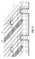
- FIG. 1Another embodiment of the cover 1 is provided with LEDs 3 that are attached to yarns 11, 12 in a woven structure 2 of conducting and non-conducting yarns 11, 12.
- Figure 3shows such an embodiment wherein the substrate 2 comprises a woven structure 2 of yarns 11, 12.
- the woven structure 2is provided with conducting yarns 11a, 12 which comprise anodes 11a and cathodes 12.
- LEDs(not shown in figure 3 ) are connected with these conducting yarns 11, 12 at locations 13.
- the configuration of the structure 2, more particularly, the yarns 11, 12,is such that the LEDs can be individually addressed.
- the structure 2can comfortably cover a part of the body and illuminate it at the same time.
- the structure 2can for example be a textile and can be combined with other (transparent) layers of textile, foil, polymers, etc. for example for extra protection of the body.
- the woven structure 2doesn't have to be a textile but may also comprise a polymer such as nylon and/or polyester, etc.
- the structure 2 of this embodimentis flexible and can have the properties of body covers like clothes.
- the electroluminescent sources 3comprises OLEDs (organic LEDs) 3.
- OLEDs 3are electroluminescent sources that can be configured to be flexible and/or transparent. Also, one OLED 3 can cover a large area of the body without being interrupted, while maintaining flexibility, so that a diffusing layer is not necessary, as opposed to many LEDs. The OLED 3 covering said large area can be driven by just one set of electrodes.
- the cover 1can be provided with one or multiple OLEDs 3.
- OLEDs 3are known in the art, and are for example described in WO 2007/054855 .
- a cover 1 not part of the present inventionis shown in figure 4 .
- This covercomprises a flexible sheet 8 with foils 2 attached on the inside, for example, but not limited to foils 2 such as the foil 2 with LEDs 3 that is shown in figure 2 .
- LEDs 3(not shown in figure 2 ) are attached to the foil 2.
- a zipper 9is provided along the edges of the sheet 8, so that the sheet 8 can be formed into a bag, for example a kind of sleeping bag.
- the sheet 8is made of a breathable material and contains strips of net material to enhance ventilation.
- the edges 18 of the sheet 8may be made of a very breathable gauze material.
- pants forming zippers 9amay be provided, adding a hybrid function to the cover.
- Figure 5shows such a cover 1, where the foils 2 with LEDs 3 are taken off.
- the foils 2are attached to the sheet 8 by means of attachment means such as buttons 9, or for example velcro, magnetic means, static electricity, sticking means, etc. so that they are exchangeable, for example for washing or changing a defect foil 2 or for washing the cover 1 without damaging the LEDs 3 and/or the electrical ciruit of the foil 2.
- the foils 2, more particularly, the LEDs 3connect with the foil connectors 14 that are provided at the location of where the foils 2 will be attached, at least approximately.
- the connectors 14can also be integrated with said attachment means 9.
- the foil connectors 14are connected to a plug contact 15, through which a connection is made with power supply 4 and in a particular embodiment, with control means 5.
- the foil connectors 14are for example connected to the contact 15 by means of conducting lines or a cable 36.
- the cable 36may be kept in place by straps 37 in the cover 1 and can easily be removed from the cover 1.
- the individual foils 2, more particularly the LEDs 3can be driven and controlled by making simple contact with the foil connectors 14.
- flaps 16are fixed to the cover 1.
- the power supply 4may comprise a battery 4, for example, but not limited to, a lithylene battery 4, which an be relatively flat shaped and preferably, relatively flexible.
- the covermay also be provided with connecting means for the electricity network, for example a plug.
- a not shown battery holderis provided for holding at least one battery 4.
- a detachable light permeable (translucent to the LED emitting wavelengths) lining 17is attached on the inside of the cover 1, over the foils 2, so that possible heat that is generated by the LEDs 3 can be decreased.
- the lining 17may comprise phase change material.
- the lining 17may add to the comfort of the cover 1.
- the lining 17may comprise multiple layers that serve various purposes, also the lining 17 can be used instead of, or as a part of above mentioned sheet 8.
- a liner 17 made of soft and bulky materialmay add to the comfort.
- the lining 17may have fluid absorbing properties.
- the lining 17may act as a diffusing and/or light scattering layer for electroluminescent point sources 3.
- the lining 17can for example be taken off the cover 1 for washing and/or exchanging.
- the lining 17may comprise a fabric or textile, or any other polymer or rubbery substance in general.
- Non-woven' fabric linings 17comprise fibers that are bonded together, for example by use of resins or mechanical entanglement, as compared to woven fabric linings, where the fibers may be held together by weaving of the yarn and/or twisting of the fibers in the yarn.
- Suitable fibersinclude natural textile fibers, such as cotton or wool fibers, regenerated fibers, such as viscose, and synthetic fibers such as polyester, polyamide (nylon) or polyacrylic fibers.
- natural textile fiberssuch as cotton or wool fibers
- regenerated fiberssuch as viscose
- synthetic fiberssuch as polyester, polyamide (nylon) or polyacrylic fibers.
- multiple layersmay be provided, for example a layer of diffusing foam can be placed in between the flexfoils and the lining 17.
- the lining 17may also comprise non-woven or spacer fabrics or foam or any other material that diffuses light and create a homogenous light panel out of an assembly of point sources of light such as LEDs 3.
- the lining 17may be configured to withstand and/or absorb faeces and/or fluids coming from the user.
- the lining 17can include a diper or the like and/or has properties to repel and/or absorp moisture and bodily fluids.
- This lining 17 or a layer thereofcan be disposable. This might for example be advantageous with an embodiment of a cover 1 for babies, providing a type of nappy function.
- the lining 17can be exchanged and washed and the rest of the cover 1 can be kept relatively clean.
- the cover 1itself is configured to withstand, repel and/or absorp faeces and/or fluids and/or can be washed, such that the electric components, for example the electroluminescent sources 3 and/or the electric circuit, will not be damaged.
- the light panelscan be encapsulated individually, collectively or in modules in a lining 17 material or for example in polymeric/elastomeric soft materials for protection and robustness.
- protective layersmay be provided in the cover 1, for example, rubbery or polymer materials.
- multiple linings 17can be provided for one cover 1.
- a cover 1can for example be as follows. A patient is placed on the cover 1 on the side of the LEDs 3, preferably on the sweat absorbing lining 17, that touches the naked skin.
- the LEDs 3expose the body of the patient preferably with blue light.
- the LEDsare configure to emit at a high-intensity narrow band blue light with a wavelength in the 450-470 nm spectrum, centered around a 450 nm peak and no light emission in the UV wavelength area.
- the foil 2contain holes, so that body heat and moisture can exit.
- the coverWhen the patient is placed on the cover 1, the cover may be closed by means of joining means 9.
- the joining means 9may comprise zippers 9, velcro, buttons and/or the cover 1 may be attached directly to the patient.
- a sleeping bagWhen the joining means 9 are joined, a sleeping bag may be formed as shown in f1 figure 8 and 9 .
- the cover 1may be provided with a pillow 34, which may also comprise electroluminescent sources 3.
- a cover for babiesis shaped for babies to one year old ( figure 9 ), other covers are shaped as an infant's sleeping bag for 1 to 4 year old children and for example have removable cotton sleeves 19 ( figure 10 ).
- a sleeping bagcan be resized to three sizes for different treatments, different and/or growing patients, for example for the following age groups: 7 to 12 year old children, 12 to 18 year olds and adult users ( figure 11 ).
- the sleeping bags 1can consist of two separate sheets 8a, 8b, each covered on one side with foils 2 (see figure 5 ).
- zippers 9are provided on the sides of the cover 1 and by zipping the sheets 8a, 8b a sleeping bag can be created.
- the upper part 20 of the sideshave 'pushbuttons' 21 and by leaving these buttons 21 open, arm openings 22 are created ( figure 12, 13 ).
- a zipper 9ais placed, to create pants 32, providing for a hybrid function for the cover 1.
- no LEDs 3are placed at knee and hip height, so that the user can comfortably move in the suit.
- flaps 16containing two extra foils 2.
- the flaps 16are used as shoulder fasteners to expose the shoulders when the cover 1 is used as a suit, as shown in figure 12 , and it can be used as a hood when it is used as a sleeping bag or suit, to enlighten the face, as shown in figure 8 and 13 .
- two arcs 23are provided, so that the hood doesn't touch the face, but is hanging on a distance above the head. This is shown in figure 8 .
- the backing material of the hoodis for example made of a net type material to create an open structure and air can flow through.
- the backing materialcould for example also comprise a porous material.
- extra material 24is attached that can be pulled up or down the leg.
- Thismay comprise elastic material to be able to clamp a part of the cover 1 against the leg.
- the cover 1is constructed by joining modular cover parts 25 with foils 2 to each other, as can be seen from figure 11 .
- These building blocksare for example provided with two foils 2 placed side to side.
- joining means 9comprise zippers 9b on the edges with which the modular cover parts 25 can be connected to the cover or may build to form a cover 1.
- the LEDsmay for example be connected by plugging small connectors 26.
- the LEDSs 3automatically connect to connectors 26 by joining the joining means 9b.
- Another embodimentis provided with conductive zippers 9b or Velcro, such that modular elements 25 connect to the electric circuit by joining the velcro.
- Other joining means 9bmay of course also be conductive and applied for like embodiments.
- the embodiment provided with the modular parts 25is for example advantageous when the user is a Crigler-Najjar patient.
- the patientcan use the cover 1 for longer periods, for example several years and adjust the cover 1 for his comfort.
- the cover 1can be enlarged by attaching a modular part 25 when the cover 1 becomes too small.
- two extra modular cover parts, with or without foils 2can be zipped to enlarge the size of the cover 1, to provide extra space for body movement during sleep.
- the cover 1can be of variable size by means of extra backing material, in which case the upper part of the cover 1 can be folded and, for example, hidden behind a zipper, for example hidden in a zipped pocket.
- the extra materialcan be revealed and foils 2 can be placed inside.
- the extra materialalready contains the electronic connectors 26 and foil connectors 14 to connect the foil 2 to the system.
- the cover 1may be provided with a cooling system, for example when the cover 1 and/or the LEDs dissipate a relative large amount of heat.
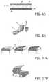
- the cooling systemfor example comprises an airconditioning apparatus (airco) 27 that is connected to the suit and blows cold air 29 between a backing material 28 and the foils 2, as shown in figure 14 and 15 . Air may also blow through the openings 10 in the foil 2 onto the body.
- airconditioning apparatusairco
- FIG. 16Another cover is provided with a liquid cooling system 30, for example as known from military suits.
- a liquid cooling system 30for example as known from military suits.
- An example of such a coveris shown in figure 16 .
- Cool wateris pumped through tube frames 31 in the cover 1 to cool the electronics and/or body.
- the cover 1may comprise a built-in sensor that measures the temperature and for example decreases the light intensity when the temperature exceeds a certain level, until the desired temperature is reached again.
- Coolingmay also be provided passively by providing the cover 1 with a frame 23b of tubes, for example shaped as hoops or arcs, in the cover, so that an air layer is created between at least a part of the body and the cover 1, as shown in figure 18 .
- an embodiment of the cover 1comprises fixation means, for example bands 33, that are for example fixed to one of the sheets 8 and can be placed for example around body support, such as a mattress.
- fixation meansfor example bands 33
- the bands 33pull the sheet 8 tight. The user can now lie on the sheet 8 without the risk of folding it during sleep.
- the cover 1, or at least the inside of the cover 1,may be provided with reflecting material so that the light of the LEDs 3 is reflected and possibly more light reaches the part of the body. Light that is transmitted to the back of the LEDs 3, may be reflected back to the front side so that it reaches the body. This will improve the light output and improve the efficiency of the cover 1.
- the cover 1may comprise other electroluminescent sources 3 than the foil 2 with LEDs 3.
- OLEDs 3 and/or LEDs 3 attached to conductive and/or non-conductive yarns 11, 12may be provided within the scope of the invention.
- Other LEDs 3 and/or other ways of attaching LEDs 3 and/or other electroluminescent sources to a substrate 2are obviously possible within the scope of the invention.
- the covermay be provided with at least one opening.
- openingsmay be provided for the head, shoes, eyes, ears and/or mouth. Openings may also be provided to pass through food, urine and/or faeces. The openings may be reopenable and/or reclosable.
- the control means 5may receive data from sensors. Sensors and/or other measurement devices are provided to provide data for the control means 5, which will send a signal to the adjustment, if necessary.
- the status of the illnesscan be measured by measuring the colour of the skin. Also moisture conditions and/or temperature conditions can be measured with known devices. Another example is measuring the colour of the light, i.e. the wavelength, to check what wavelength is being emitted.
- the systemi.e. control means 5, can self-adjust in time, for example according to a pre-set schedule. Wavelength settings and/or intensity settings can be adjusted as well as the temperature and/or moisture conditions of the cover 1.
- a cover 1may comprise a hat, cap and/or visor 38, provided with electroluminescent sources 3, for example (O)LEDs 3.
- the blue lightis emitted to the area 39 around the eyes, as can be seen from figure 19 .
- the blue lightis emitted to the area around the bottom eyelids, from above the forehead. Therefore, preferably a revitalising head cover 1 is provided with LEDs in the cap portion 39.
- the light of the electroluminescent sources 3can also be reflected to the area of the eyes 39.
- the revitalising head covers 1may be provided with transparent electroluminescent sources 3, for example OLEDs 3, such that the electroluminescent sources are attached to a transparent surface, for example in the glasses 42 and/or a transparent visor.
- These types of revitalising head covers 1can be revitalising, for example in tiring moments, for example when working at night, for example truck driving at night or other night shift work. There is little loss of comfort.
- the LEDscan be integrated with the fabric, for example such as explained above; for example by means of a foil 2 and/or integration of LEDs 3 with conductive and non-conductive yarns 11, 12.
- Flexible substrates and/or flexible electroluminescent sources 3can be integrated with the fabric of the revitalising head cover 1.
- OLEDscould be attached to the head cover as well.
- Different coversinvolve power supplies such as batteries, fuel cells, etc.
- Control meanscould be integrated as well.
- Attachment means for the electroluminescent sourcesfor example include glue.
- phototherapycan be applied for wound healing.
- wounds on women's breastparticularly around the nipples during breastfeeding, can also be treated by phototherapy. If these types of breast wounds are not treated in time, infections might occur and/or breastfeeding has to be interrupted. Since breastfeeding may take place for example every three or four hours and each session may take for example up to an hour, there might be insufficient time for the wound(s) to heal. Although for example for pain relief certain creams are sometimes used, those generally do not accelerate breast wound healing.
- a cover 1 for emitting light at certain wavelengthsBy applying a cover 1 for emitting light at certain wavelengths to women's breasts, the healing of the wounds, especially near the nipples, can be accelerated and/or wounds and/or infections may be prevented. Therefore it is advantageous when a cover 1 can be worn near the breasts, or at least near the nipples. Furthermore, a cover 1 for breast wound healing may be used to prevent wounds or for cosmetic purposes.
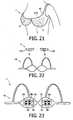
- a cover 1may be at least partly preshaped in the form of a nipple, possibly including at least part of the areola mammae and/or further breast.
- the cover 1 for breast wound healingcan be flexible, wherein it is configured to at least partly follow the curves of the female breast.
- the cover 1may be constructed like a bra 43 or a replaceable lining 17A for a bra 43.
- a bra 43is shown, which is provided with elements 2, 32, 17A that are indicated with dashed lines.
- This coverhas advantageously combined electroluminescent sources like LEDs 3 with bras 43 so that a cover 1 functions as a phototherapeutic bra 43.
- the lining 17Amay be applied, among others, for comfort, light scattering and for example absorption of leaking fluids from the breast.
- the electroluminescent sourcesmay comprise LEDs 3 that emit light in the red and/or infrared region, which is advantageous for wound healing. With the aid of control means 5, the wavelength and/or intensity of at least a part of the LEDs can be changed to apply a more optimised treatment.
- the bra 43for example comprises foils 2, knitted, woven and/or non-woven textiles 2 and/or conductive and non-conductive yarns 11, 12 to which the LEDs 3 are attached, as already described above.
- the foil 2 with LEDs 3can for example be attached to or laid in the inside of the bra 43, wherein for example a lining 17A or another type of layer acts as a diffusing layer.
- the cover 1 for breast wound healingcan be put in a compartment that is provided in a bra 43.
- a phototherapeutic bra 43can be conveniently worn like a conventional bra.
- the cover 1doesn't need to be in direct contact with skin and one or more layers can be put in between the cover 1 and the skin.
- the lining 17Amay include LEDs 3 and/or a light scattering and/or diffusing layer, and can be placed in the bra 43.
- the lining 17Amay be fixedly integrated with the bra 43 or can be placed in a conventional bra 43 in a replaceable way, as shown in figure 22 .
- the lining 17Amay comprise joining means 9, such as for example comprising Velcro-like material, buttons, etc.
- the cover 1may comprise a nursing pad or another pad, to be put against a breast. Such a nursing pad may prevent and/or absorb leakage and apply phototherapy by having LEDs 3 applied.
- the cover 1 for women's breastmay be integrated or joinable with T-shirts, tops, patches, etc. To enhance the therapy, phototherapy can be applied in combination with creams and/or agents.
- the bra 43can self adjusts its therapy according to the size and/or state of the wound(s) in time.
- software and/or predetermined dataare used so that the phototherapy can be performed according to measurements and predetermined data.
- the light intensity of at least a part of the LEDs 3can be adjusted.
- Sensorscan be used that measure temperature, colour and/or emittance of the skin.
- the LEDs 3may be configured to be light sources 3A as well as sensors 3B, as shown in figure 23 .
- the reflectivity of the skinis measured with the LEDs 3B that sense light that is emitted by the LEDs 3A and reflected by the skin.
- the state of specific parts of the bodyfor example the nipples can be obtained by comparing with predetermined data and/or changes of the nipples in time, for example hours or days.
- the lining 17A and/or LEDs 3may be shaped to fit around a nipple and/or the area around the nipple.
- a cover 1may for example configured for any type of phototherapy, not specifically described in the above text.
- body coverused for wound healing can also be used for pain relief, e.g. for the treatment of muscle pain or joint pain.
Landscapes
- Health & Medical Sciences (AREA)
- Engineering & Computer Science (AREA)
- Biomedical Technology (AREA)
- Pathology (AREA)
- Nuclear Medicine, Radiotherapy & Molecular Imaging (AREA)
- Radiology & Medical Imaging (AREA)
- Life Sciences & Earth Sciences (AREA)
- Animal Behavior & Ethology (AREA)
- General Health & Medical Sciences (AREA)
- Public Health (AREA)
- Veterinary Medicine (AREA)
- Radiation-Therapy Devices (AREA)
- Professional, Industrial, Or Sporting Protective Garments (AREA)
- Corsets Or Brassieres (AREA)
- Electroluminescent Light Sources (AREA)
Description
- The invention relates in general to a body cover, comprising a substrate, for covering at least part of a human body, and at least one electroluminescent source coupled to the substrate.
- Light is known to have beneficial beneficial effects on humans. In fields such as phototherapy light can be used for healing purposes. A case where light treatment is used is hyperbilirubinemia. Hyperbilirubinemia patients are daily exposed to a high dose of blue light for a period up to eleven hours. Hyperbilirubinemia is a disorder of bilirubin metabolism. Bilirubin is the toxic waste product of the worn-out red blood cells that get converted by an enzyme produced by the liver, which excretes the bilirubin. Hyperbilirubinemia patients lack this enzyme, which causes an accumulation of the bilirubin in the tissue. This results in jaundice of the skin and the eyes. Neonatal jaundice and crigler najjar are two types of Hyperbilirubinemia. Crigler najjar patients range from the age of infant to adult and need daily light therapy for life, for various periods as long as 11 hours a day. Neonatal patients oftentimes need continuous light therapy for a few days.
- Bilirubin degrades under influence of phototherapy. The therapeutic efficacy of phototherapy is, among others, dependent on the spectral light qualities, the intensity of the light, the exposed body surface area and the duration of exposure. A high-intensity narrow band blue light is used with a wavelength in the 450-470 nm spectrum, centered around a 450 nm peak and no light emission in the UV wavelength area. Light intensities of at least 5mW/cm2 up to 10 mW/cm2 and full body exposure are used for keeping treatment durations relatively acceptible.
- Known treatments for jaundice, particularly baby jaundice, combine a warming box with light treatment. The warming box is required since the baby has to be naked for the efficiency of the light treatment, making the normal process of taking care of the baby, for example breast feeding, more difficult and limiting its freedom of movement. The eyes of the baby are covered to be protected against bright light.
- Known phototherapy devices for treatment of hyperbilirubinemia commonly use fluorescent tubes or halogen spots. Disadvantages of these devices include physical size and shape, heat production, unstable and broad wavelength light output, limited body surface area illumination and UV radiation. The conventional phototherapy devices illuminate the patients from one side, for example, because it is uncomfortable to lie on a transparant plastic sheet or transparant fabric over the hot lamps for a long period. In some cases a transparent bed provides the opportunity for exposing the body from both sides, however, this bed doesn't meet the requirements of a comfortable bed.
- Furthermore, a small fibreoptic sheet to illuminate a baby is developed. Drawbacks are the limited size and relative low intensity. Hence it is commonly used in combination with other phototherapy devices and besides, it can not be used for older patients.
- Furthermore it is said that light having a wavelength of approximately 450 nm emitted to human eyes has a revitalising effect on a person. It is also known that phototherapy is used for stimulating purposes of cells in/near the skin, for example in wound healing, at different wavelengths within a wide range up to the infrared region.
US 6,596,016 discloses a phototherapy garment which contains a flexible backing material, a transparent liner, and a flexible printed circuit sheet containing surface-mounted light-emitting diodes positioned between the backing material. The garment may contain a feedback system with skin bilirubin sensors so that the intensity level and duration of the light therapy can be based on the bilirubin in the skin.US 2004/0138726 discloses a device for delivering light to the blood supply of a human body through a non-ocular skin area. The device has a plurality of light emitting diodes spaced apart from each other and extending through apparatuses for emitting light to the body. The device provides wavelengths of light within a specifically-determined range of intensities and a specifically determined angels of illumination. This document discloses the preamble ofclaim 1.US 6,045,575 discloses an apparatus for treating neonatal jaundice. The garment has semiconductor light sources affixed thereto for radiating toward the "inside" of the garment when the infant is dressed in the garment.US6,858,036 discloses a device for acupuncture comprising a pressure plate. The pressure plate is provided with a plurality of fitting rods and when it is desired to assemble two or more pressure plates into an assembly the fitting rods of one plate are elastically coupled to the channelled fitting tubes of another plate.US2005/085875 discloses a system and method of administering photon therapy. The system includes a plurality of treatment modules and a case for housing the photon emitter. The case includes linkers for linking each of the treatment modules to form an arbitrary modular pattern.- An object of the invention is to provide a relatively comfortable way of applying phototherapy.
- This object and other objects are achieved by a body cover according to
claim 1. - Said object and other objects are also achieved by a body cover according to the dependent claims.
Fig. 1 shows a diagram of a cover;Fig. 2 schematically shows a top view foil with LEDs;Fig. 3 schematically shows a perspective view of an interwoven yarn structure;Figs. 4, 5 and6 show a cover;Figs. 7 and 8 show a cover as a sleeping bag;Fig. 9 shows a cover as a sleeping bag for babies;Fig. 10 shows a cover as a sleeping bag for infants;Fig. 11 shows a modular cover for different sizes;Fig. 12 shows a cover as a suit;Fig. 13 shows a cover as a suit with a hood;Fig. 14 shows a cover with an air cooling system;Fig. 15 shows a detail of the air cooling system;Fig. 16 shows a cover with a liquid cooling system;Fig. 17 shows a mattress with a cover;Fig. 18 shows a cover with arcs;Fig. 19 shows a cover as a visor with LEDs;Fig. 20 shows a cover as glasses with LEDs;Fig. 21 shows a cover as a bra with LEDs;Fig. 22 shows a cover as a lining for a bra with LEDs;Fig. 23 shows a cover as a bra with LEDs.- In this description, identical or corresponding parts have identical or corresponding reference numerals. The exemplary embodiments shown should not be construed to be limitative in any manner and serve merely as illustration.
- A
cover 1 with electroluminescent sources for illuminating at least part of the body is shown infigure 1 . Thecover 1 comprises asubstrate 2 which has electroluminescentsources 3 attached. Theelectroluminescent sources 3 are individually driven bypower supply 4, which is controlled by control means 5. To individually address theelectroluminescent sources 3, thepower supply 4 may comprise a driver unit. Wavelength adjusting means 6 are provided for the possibility of varying the wavelength of at least a part of theelectroluminescent sources 3 and are controlled by control means 5. By means of a user interface 7 the control means 5 can be set and/or adjusted to specify the settings of theelectroluminescent sources 3. For instance by signalling the wavelength adjusting means 6, the wavelength of theelectroluminescent sources 3 can be individually controlled, and/or it can be controlled in groups and/or all thesources 3 can be controlled. Also, by signalling the driver unit, the light output of thesources 3 can be controlled and/or turned on and off, for example. - The wavelength can for example be varied by turning on and off
different electroluminescent sources 3 with different wavelengths. It is also possible to apply wavelength filters. By selecting the proper filters the proper wavelength can be selected. It is also possible to change the wavelength by varying the temperature ofLEDs 3. Other wavelength adjusting means include using phosphors, preferably in combination with PWM (pulse width modulation) or varying the forward current, also preferably in combination with PWM. PWM can for example be applied to make sure that the intensity stays as desired while the wavelength is adjusted. Furthermore, the intensity of the light of theelectroluminescent sources 3 can for example be set by means of adjusting the current through thepower supply 4 for varying the light output. Of course, there are more ways of varying intensity, such as, by using PWM and/or by turning an amount of theelectroluminescent sources 3 on/off, etc. Theelectroluminescent sources 3 are configured to emit therapeutic light to a part of a human body. Therefore, thecover 1 may for example be wrapped around a part of a human body, and/or around a body support such as a pillow, bed, chair, etc. Thecover 1 is flexible and may be folded so that it is portable. Joining means 9 that join together are provided so that thecover 1 can be configured in a bag or cylinder shape and the part of the body can be surrounded by light from theelectroluminescent sources 3. Joining means 9 may for example comprise, buttons, zippers, velcro, elements that can be tied together, elastic means for closing around at least a part of a body and/or body support, etc. - In an embodiment of the
cover 1, theelectroluminescent sources 3 comprise light emitting sources like LEDs (Light Emitting Diodes) 3, for example gallium-nitride blue LEDs. The latter are relatively effective, safe and convenient phototherapy devices and capable of delivering high intensity narrow wavelength band light. Furthermore, they can be configured into flexible devices, such ascover 1. Thecover 1 is provided with asubstrate 2 that is made of aflexible foil 2, in this case withLEDs 3 attached to it. Examples of such aflexible foil 2 provided with LEDs can be found inWO 2006/129272 . An embodiment of thefoil 2, at least, a part of afoil 2, withLEDs 3, is shown infigure 2 . As can be seen fromfigure 2 thefoil 2 is provided with rows and columns ofopenings 10, between theLEDs 3. Thefoil 2 can be constructed in different sizes. Theopenings 10 of thefoil 2 increase flexibility and the breathing properties of thecover 1. Different embodiments of thefoil 2 for example comprise knitted, woven and non-woven textiles and/or polymers, rubbery materials, spacer fabrics, foams,etc. Thefoil 2 is provided with not shown conducting lines of an electrical circuit, between theopenings 10, for supplying power to and/or controlling theLEDs 3. - Another embodiment of the
cover 1 is provided withLEDs 3 that are attached toyarns 11, 12 in awoven structure 2 of conducting andnon-conducting yarns 11, 12. Such an embodiment can be found inWO 2006/129272 .Figure 3 shows such an embodiment wherein thesubstrate 2 comprises awoven structure 2 ofyarns 11, 12. Thewoven structure 2 is provided with conductingyarns anodes 11a andcathodes 12. LEDs (not shown infigure 3 ) are connected with these conductingyarns 11, 12 atlocations 13. In an embodiment, the configuration of thestructure 2, more particularly, theyarns 11, 12, is such that the LEDs can be individually addressed. Thestructure 2 can comfortably cover a part of the body and illuminate it at the same time. Thestructure 2 can for example be a textile and can be combined with other (transparent) layers of textile, foil, polymers, etc. for example for extra protection of the body. Of course, thewoven structure 2 doesn't have to be a textile but may also comprise a polymer such as nylon and/or polyester, etc. Thestructure 2 of this embodiment is flexible and can have the properties of body covers like clothes. - In another embodiment the
electroluminescent sources 3 comprises OLEDs (organic LEDs) 3.OLEDs 3 are electroluminescent sources that can be configured to be flexible and/or transparent. Also, oneOLED 3 can cover a large area of the body without being interrupted, while maintaining flexibility, so that a diffusing layer is not necessary, as opposed to many LEDs. TheOLED 3 covering said large area can be driven by just one set of electrodes. Thecover 1 can be provided with one ormultiple OLEDs 3.OLEDs 3 are known in the art, and are for example described inWO 2007/054855 . - A
cover 1 not part of the present invention is shown infigure 4 . This cover comprises aflexible sheet 8 withfoils 2 attached on the inside, for example, but not limited to foils 2 such as thefoil 2 withLEDs 3 that is shown infigure 2 . LEDs 3 (not shown infigure 2 ) are attached to thefoil 2. Azipper 9 is provided along the edges of thesheet 8, so that thesheet 8 can be formed into a bag, for example a kind of sleeping bag. For example, thesheet 8 is made of a breathable material and contains strips of net material to enhance ventilation. Theedges 18 of thesheet 8 may be made of a very breathable gauze material. Also pants formingzippers 9a may be provided, adding a hybrid function to the cover.Figure 5 shows such acover 1, where thefoils 2 withLEDs 3 are taken off. Thefoils 2 are attached to thesheet 8 by means of attachment means such asbuttons 9, or for example velcro, magnetic means, static electricity, sticking means, etc. so that they are exchangeable, for example for washing or changing adefect foil 2 or for washing thecover 1 without damaging theLEDs 3 and/or the electrical ciruit of thefoil 2. When attached, thefoils 2, more particularly, theLEDs 3, connect with thefoil connectors 14 that are provided at the location of where thefoils 2 will be attached, at least approximately. Theconnectors 14 can also be integrated with said attachment means 9. Thefoil connectors 14 are connected to aplug contact 15, through which a connection is made withpower supply 4 and in a particular embodiment, with control means 5. Thefoil connectors 14 are for example connected to thecontact 15 by means of conducting lines or acable 36. Thecable 36 may be kept in place bystraps 37 in thecover 1 and can easily be removed from thecover 1. In this way, the individual foils 2, more particularly theLEDs 3, can be driven and controlled by making simple contact with thefoil connectors 14. For illumination around, or on the head or shoulders, flaps 16 are fixed to thecover 1. - The
power supply 4 may comprise abattery 4, for example, but not limited to, alithylene battery 4, which an be relatively flat shaped and preferably, relatively flexible. The cover may also be provided with connecting means for the electricity network, for example a plug. A not shown battery holder is provided for holding at least onebattery 4. For continuous use of thecover 1 it is advantageous ifbatteries 4 can be exchanged without interfering with the functioning of thecover 1, particularly theelectroluminescent sources 3. - In the cover (not part of the present invention) that is shown in
figure 6 , a detachable light permeable (translucent to the LED emitting wavelengths) lining 17 is attached on the inside of thecover 1, over thefoils 2, so that possible heat that is generated by theLEDs 3 can be decreased. For example, the lining 17 may comprise phase change material. The lining 17 may add to the comfort of thecover 1. The lining 17 may comprise multiple layers that serve various purposes, also the lining 17 can be used instead of, or as a part of above mentionedsheet 8. For example, aliner 17 made of soft and bulky material may add to the comfort. - The lining 17 may have fluid absorbing properties. The lining 17 may act as a diffusing and/or light scattering layer for
electroluminescent point sources 3. The lining 17 can for example be taken off thecover 1 for washing and/or exchanging. The lining 17 may comprise a fabric or textile, or any other polymer or rubbery substance in general. Non-woven'fabric linings 17 comprise fibers that are bonded together, for example by use of resins or mechanical entanglement, as compared to woven fabric linings, where the fibers may be held together by weaving of the yarn and/or twisting of the fibers in the yarn. Suitable fibers include natural textile fibers, such as cotton or wool fibers, regenerated fibers, such as viscose, and synthetic fibers such as polyester, polyamide (nylon) or polyacrylic fibers. To get a more homogeneous light emitting surface, multiple layers may be provided, for example a layer of diffusing foam can be placed in between the flexfoils and thelining 17. The lining 17 may also comprise non-woven or spacer fabrics or foam or any other material that diffuses light and create a homogenous light panel out of an assembly of point sources of light such asLEDs 3. - The lining 17 may be configured to withstand and/or absorb faeces and/or fluids coming from the user. For example, the lining 17 can include a diper or the like and/or has properties to repel and/or absorp moisture and bodily fluids. This lining 17 or a layer thereof can be disposable. This might for example be advantageous with an embodiment of a
cover 1 for babies, providing a type of nappy function. The lining 17 can be exchanged and washed and the rest of thecover 1 can be kept relatively clean. Alternatively, thecover 1 itself is configured to withstand, repel and/or absorp faeces and/or fluids and/or can be washed, such that the electric components, for example theelectroluminescent sources 3 and/or the electric circuit, will not be damaged. Alternatively, the light panels can be encapsulated individually, collectively or in modules in alining 17 material or for example in polymeric/elastomeric soft materials for protection and robustness. For this, protective layers may be provided in thecover 1, for example, rubbery or polymer materials. Of coursemultiple linings 17 can be provided for onecover 1. - The use of a
cover 1 can for example be as follows. A patient is placed on thecover 1 on the side of theLEDs 3, preferably on thesweat absorbing lining 17, that touches the naked skin. TheLEDs 3 expose the body of the patient preferably with blue light. Preferably, the LEDs are configure to emit at a high-intensity narrow band blue light with a wavelength in the 450-470 nm spectrum, centered around a 450 nm peak and no light emission in the UV wavelength area. As shown infigure 2 , thefoil 2 contain holes, so that body heat and moisture can exit. - When the patient is placed on the
cover 1, the cover may be closed by means of joiningmeans 9. The joining means 9 may comprisezippers 9, velcro, buttons and/or thecover 1 may be attached directly to the patient. When the joiningmeans 9 are joined, a sleeping bag may be formed as shown in f1figure 8 and9 . Thecover 1 may be provided with apillow 34, which may also compriseelectroluminescent sources 3. - Different covers have different sizes. A cover for babies is shaped for babies to one year old (
figure 9 ), other covers are shaped as an infant's sleeping bag for 1 to 4 year old children and for example have removable cotton sleeves 19 (figure 10 ). In an embodiment a sleeping bag can be resized to three sizes for different treatments, different and/or growing patients, for example for the following age groups: 7 to 12 year old children, 12 to 18 year olds and adult users (figure 11 ). - The
sleeping bags 1 can consist of twoseparate sheets figure 5 ). For example,zippers 9 are provided on the sides of thecover 1 and by zipping thesheets upper part 20 of the sides have 'pushbuttons' 21 and by leaving thesebuttons 21 open,arm openings 22 are created (figure 12, 13 ). In the middle of bothsheets 8 azipper 9a is placed, to createpants 32, providing for a hybrid function for thecover 1. Preferably, noLEDs 3 are placed at knee and hip height, so that the user can comfortably move in the suit. - One of said
sheets 8a is provided withflaps 16 containing twoextra foils 2. In an embodiment, theflaps 16 are used as shoulder fasteners to expose the shoulders when thecover 1 is used as a suit, as shown infigure 12 , and it can be used as a hood when it is used as a sleeping bag or suit, to enlighten the face, as shown infigure 8 and13 . When used as a hood while sleeping, twoarcs 23 are provided, so that the hood doesn't touch the face, but is hanging on a distance above the head. This is shown infigure 8 . The backing material of the hood is for example made of a net type material to create an open structure and air can flow through. The backing material could for example also comprise a porous material. - Preferably, at the bottom part of the
cover 1 extra material 24 is attached that can be pulled up or down the leg. This may comprise elastic material to be able to clamp a part of thecover 1 against the leg. - According to the invention the
cover 1 is constructed by joiningmodular cover parts 25 withfoils 2 to each other, as can be seen fromfigure 11 . These building blocks are for example provided with twofoils 2 placed side to side. In the shown embodiment, joiningmeans 9 comprisezippers 9b on the edges with which themodular cover parts 25 can be connected to the cover or may build to form acover 1. The LEDs may for example be connected by pluggingsmall connectors 26. In another embodiment (not shown), theLEDSs 3 automatically connect toconnectors 26 by joining the joiningmeans 9b. Another embodiment is provided withconductive zippers 9b or Velcro, such thatmodular elements 25 connect to the electric circuit by joining the velcro. Other joiningmeans 9b may of course also be conductive and applied for like embodiments. The embodiment provided with themodular parts 25 is for example advantageous when the user is a Crigler-Najjar patient. By means of the variable size, the patient can use thecover 1 for longer periods, for example several years and adjust thecover 1 for his comfort. Thecover 1 can be enlarged by attaching amodular part 25 when thecover 1 becomes too small. In an embodiment of thecover 1, between thesheets foils 2, can be zipped to enlarge the size of thecover 1, to provide extra space for body movement during sleep. - Alternatively, the
cover 1 can be of variable size by means of extra backing material, in which case the upper part of thecover 1 can be folded and, for example, hidden behind a zipper, for example hidden in a zipped pocket. When the user grows and thecover 1 becomes relatively too small, the extra material can be revealed and foils 2 can be placed inside. The extra material already contains theelectronic connectors 26 andfoil connectors 14 to connect thefoil 2 to the system. - The
cover 1 may be provided with a cooling system, for example when thecover 1 and/or the LEDs dissipate a relative large amount of heat. The cooling system for example comprises an airconditioning apparatus (airco) 27 that is connected to the suit and blowscold air 29 between a backingmaterial 28 and thefoils 2, as shown infigure 14 and15 . Air may also blow through theopenings 10 in thefoil 2 onto the body. - Another cover is provided with a
liquid cooling system 30, for example as known from military suits. An example of such a cover is shown infigure 16 . Cool water is pumped through tube frames 31 in thecover 1 to cool the electronics and/or body. To prevent the risk of overheating, thecover 1 may comprise a built-in sensor that measures the temperature and for example decreases the light intensity when the temperature exceeds a certain level, until the desired temperature is reached again. - Cooling may also be provided passively by providing the
cover 1 with aframe 23b of tubes, for example shaped as hoops or arcs, in the cover, so that an air layer is created between at least a part of the body and thecover 1, as shown infigure 18 . - To prevent wrinkling and folding of the
foils 2 because of the moving an embodiment of thecover 1 comprises fixation means, forexample bands 33, that are for example fixed to one of thesheets 8 and can be placed for example around body support, such as a mattress. Such a configuration is shown infigure 17A and B . Thebands 33 pull thesheet 8 tight. The user can now lie on thesheet 8 without the risk of folding it during sleep. - The
cover 1, or at least the inside of thecover 1, may be provided with reflecting material so that the light of theLEDs 3 is reflected and possibly more light reaches the part of the body. Light that is transmitted to the back of theLEDs 3, may be reflected back to the front side so that it reaches the body. This will improve the light output and improve the efficiency of thecover 1. - The
cover 1 may comprise otherelectroluminescent sources 3 than thefoil 2 withLEDs 3. Forexample OLEDs 3 and/orLEDs 3 attached to conductive and/ornon-conductive yarns 11, 12 may be provided within the scope of the invention.Other LEDs 3 and/or other ways of attachingLEDs 3 and/or other electroluminescent sources to asubstrate 2 are obviously possible within the scope of the invention. - The cover may be provided with at least one opening. Next to arm
openings 22, openings may be provided for the head, shoes, eyes, ears and/or mouth. Openings may also be provided to pass through food, urine and/or faeces. The openings may be reopenable and/or reclosable. - The control means 5 may receive data from sensors. Sensors and/or other measurement devices are provided to provide data for the control means 5, which will send a signal to the adjustment, if necessary. For example, the status of the illness can be measured by measuring the colour of the skin. Also moisture conditions and/or temperature conditions can be measured with known devices. Another example is measuring the colour of the light, i.e. the wavelength, to check what wavelength is being emitted. In this way, the system, i.e. control means 5, can self-adjust in time, for example according to a pre-set schedule. Wavelength settings and/or intensity settings can be adjusted as well as the temperature and/or moisture conditions of the
cover 1. - Blue light in a wavelength spectrum of approximately 440 to 480nm, for example approximately 450nm can be useful for revitalizing a person through the eyes. Therefore, a
cover 1 may comprise a hat, cap and/orvisor 38, provided withelectroluminescent sources 3, for example (O)LEDs 3. The blue light is emitted to thearea 39 around the eyes, as can be seen fromfigure 19 . Preferably, the blue light is emitted to the area around the bottom eyelids, from above the forehead. Therefore, preferably a revitalisinghead cover 1 is provided with LEDs in thecap portion 39. Of course the light of theelectroluminescent sources 3 can also be reflected to the area of theeyes 39. Another cover has the shape ofglasses 40, where the LEDs can for example be provided in theportion 41 above theglasses 42, as can be seen fromfigure 20 . The revitalising head covers 1 may be provided withtransparent electroluminescent sources 3, forexample OLEDs 3, such that the electroluminescent sources are attached to a transparent surface, for example in theglasses 42 and/or a transparent visor. These types of revitalising head covers 1 can be revitalising, for example in tiring moments, for example when working at night, for example truck driving at night or other night shift work. There is little loss of comfort. The LEDs can be integrated with the fabric, for example such as explained above; for example by means of afoil 2 and/or integration ofLEDs 3 with conductive andnon-conductive yarns 11, 12. Flexible substrates and/orflexible electroluminescent sources 3 can be integrated with the fabric of the revitalisinghead cover 1. Of course OLEDs could be attached to the head cover as well. Different covers involve power supplies such as batteries, fuel cells, etc. Control means could be integrated as well. Attachment means for the electroluminescent sources for example include glue. - As mentioned above, phototherapy can be applied for wound healing. For example, wounds on women's breast, particularly around the nipples during breastfeeding, can also be treated by phototherapy. If these types of breast wounds are not treated in time, infections might occur and/or breastfeeding has to be interrupted. Since breastfeeding may take place for example every three or four hours and each session may take for example up to an hour, there might be insufficient time for the wound(s) to heal. Although for example for pain relief certain creams are sometimes used, those generally do not accelerate breast wound healing.
- By applying a
cover 1 for emitting light at certain wavelengths to women's breasts, the healing of the wounds, especially near the nipples, can be accelerated and/or wounds and/or infections may be prevented. Therefore it is advantageous when acover 1 can be worn near the breasts, or at least near the nipples. Furthermore, acover 1 for breast wound healing may be used to prevent wounds or for cosmetic purposes. - For example, a
cover 1 may be at least partly preshaped in the form of a nipple, possibly including at least part of the areola mammae and/or further breast. Also, thecover 1 for breast wound healing can be flexible, wherein it is configured to at least partly follow the curves of the female breast. Thecover 1 may be constructed like abra 43 or areplaceable lining 17A for abra 43. Infigure 21 abra 43 is shown, which is provided withelements LEDs 3 withbras 43 so that acover 1 functions as aphototherapeutic bra 43. Thelining 17A may be applied, among others, for comfort, light scattering and for example absorption of leaking fluids from the breast. The electroluminescent sources may compriseLEDs 3 that emit light in the red and/or infrared region, which is advantageous for wound healing. With the aid of control means 5, the wavelength and/or intensity of at least a part of the LEDs can be changed to apply a more optimised treatment. Thebra 43 for example comprisesfoils 2, knitted, woven and/ornon-woven textiles 2 and/or conductive andnon-conductive yarns 11, 12 to which theLEDs 3 are attached, as already described above. Thefoil 2 withLEDs 3 can for example be attached to or laid in the inside of thebra 43, wherein for example alining 17A or another type of layer acts as a diffusing layer. Thecover 1 for breast wound healing can be put in a compartment that is provided in abra 43. In these and other ways, aphototherapeutic bra 43 can be conveniently worn like a conventional bra. Of course, thecover 1 doesn't need to be in direct contact with skin and one or more layers can be put in between thecover 1 and the skin. - The
lining 17A may includeLEDs 3 and/or a light scattering and/or diffusing layer, and can be placed in thebra 43. Thelining 17A may be fixedly integrated with thebra 43 or can be placed in aconventional bra 43 in a replaceable way, as shown infigure 22 . For this, thelining 17A may comprise joiningmeans 9, such as for example comprising Velcro-like material, buttons, etc. Thecover 1 may comprise a nursing pad or another pad, to be put against a breast. Such a nursing pad may prevent and/or absorb leakage and apply phototherapy by havingLEDs 3 applied. Thecover 1 for women's breast may be integrated or joinable with T-shirts, tops, patches, etc. To enhance the therapy, phototherapy can be applied in combination with creams and/or agents. - With the aid of sensors and control means 5, as mentioned above, the
bra 43 can self adjusts its therapy according to the size and/or state of the wound(s) in time. For this, software and/or predetermined data are used so that the phototherapy can be performed according to measurements and predetermined data. For example, the light intensity of at least a part of theLEDs 3 can be adjusted. Sensors can be used that measure temperature, colour and/or emittance of the skin. TheLEDs 3 may be configured to belight sources 3A as well assensors 3B, as shown infigure 23 . In an embodiment, the reflectivity of the skin is measured with theLEDs 3B that sense light that is emitted by theLEDs 3A and reflected by the skin. From this reflectivity information, the state of specific parts of the body, for example the nipples can be obtained by comparing with predetermined data and/or changes of the nipples in time, for example hours or days. Thelining 17A and/orLEDs 3 may be shaped to fit around a nipple and/or the area around the nipple. - Many variations are possible within the framework of the invention as outlined by the claims. A
cover 1 may for example configured for any type of phototherapy, not specifically described in the above text. - For instance, although in relation to wound healing a bra is discussed, other body covers discussed in the description can be used for wound healing purposes too.
- Furthermore the body cover, used for wound healing can also be used for pain relief, e.g. for the treatment of muscle pain or joint pain.
Claims (16)
- Body cover (1) for covering at least part of a human body, wherein the cover is configured to at least partly surround at least a part of the human body and/or a body support, wherein the body cover (1) comprises multiple modular body cover parts (25) that are joined together to form the body cover (1), wherein a plurality of the multiple body cover parts (25) comprise at least one electroluminescent source (3) coupled to a substrate (2), for illuminating at least a part of the human body; and wherein the substrate (2) comprises a flexible and foldable foil,characterised in that the multiple modular body cover parts are detachably joined together.
- Body cover according to claim 1, wherein the at least one electroluminescent source (3) is configured to emit blue light between a wavelength of 440nm and 480nm, preferably between 445nm and 470nm, more preferably approximately 450 nm.
- Body cover according to any one of the preceding claims, wherein the cover comprises an element (16) configured to cover at least a part of a head to illuminate at least one eye.
- Body cover according to any one of the preceding claims, having a thermal conditions and/or moisture conditions regulating configuration.
- Body cover according to any one of the preceding claims, comprising control means (5) provided with wavelength settings and/or intensity settings adjusting means, for the at least one electroluminescent source (3), said means preferably comprising local settings adjustment means.
- Body cover according to claim 4 or 5, wherein control means (5) are provided, comprising at least a processing circuit, wherein the processing circuit is configured to adjust and/or monitor at least one of said conditions and/or settings, preferably by measuring said at least one of said settings and/or conditions, comparing at least one measured value to at least one pre-set value and adjusting/keeping said at least one of said settings and/or conditions in correspondence with the pre-set value.
- Body cover according to any one of the claims 5 or 6, wherein said modular cover part(s) (25) are configured to connect to the control means (5).
- Body cover according to claim 7, wherein joining means (9b) are configured for connecting said modular cover parts(s) (25) by joining the joining means (9b).
- Body cover according to any one of the preceding claims, wherein openings (10) are provided in the at least one substrate and/or in the at least one electroluminescent source and/or between multiple electroluminescent sources (3).
- Body cover according to any one of the preceding claims, wherein the at least one substrate (2) comprises at least one sheet (8) of foil, wherein the foil comprises knitted textile and/or polymers, rubbery materials, spacer fabrics, and wherein the at least one electroluminescent source (3) is attached to the at least one sheet (8).
- Body cover according to claim 10, wherein said sheet (8) comprises at least one partly conductive yarn (11, 12), wherein the at least one electroluminescent source (3) is attached to and/or between at least partly conductive yarns (11, 12).
- Body cover according to any one of the preceding claims, wherein the cover (1) comprises a frame (23; 23b) for keeping the cover in a substantially pre-shaped condition and/or for allowing temperature regulating means (27, 29; 30, 31) to pass through.
- Body cover as claimed in claim 1, comprising sensor(s) for measuring at least one of body colour, temperature, humidity, wavelength and/or intensity of the light and means (5) for comparing at least one of the measured values with at least one pre-set value and adjusting the wavelength and/or intensity of the at least one electroluminescent source (3) according to the pre-set.
- Body cover as claimed in claim 1, comprising means (6) for adjusting the wavelength of at least one electroluminescent source locally, whereas another (part of) the electroluminescent source (3) emits at a substantially different wavelength then the adjusted wavelength value, or doesn't emit.
- Body cover according to any one of any one of the preceding the claims, wherein the cover (1) is a breast cover (43) for covering at least part of a women's breast, and wherein it is at least partially configured to follow the curves of women's breasts, preferably to function as a bra.
- Body cover according to claim 15, comprising a light diffusing layer (17A).
Priority Applications (1)
| Application Number | Priority Date | Filing Date | Title |
|---|---|---|---|
| EP07705735AEP1984077B1 (en) | 2006-02-06 | 2007-01-30 | Body cover, glasses and/or at least partial head cover for radiating at least part of a human body |
Applications Claiming Priority (3)
| Application Number | Priority Date | Filing Date | Title |
|---|---|---|---|
| EP06003887 | 2006-02-06 | ||
| PCT/IB2007/050305WO2007091188A2 (en) | 2006-02-06 | 2007-01-30 | Body cover, glasses and/or at least partial head cover, method for radiating at least part of a human body and use of a body cover |
| EP07705735AEP1984077B1 (en) | 2006-02-06 | 2007-01-30 | Body cover, glasses and/or at least partial head cover for radiating at least part of a human body |
Publications (2)
| Publication Number | Publication Date |
|---|---|
| EP1984077A2 EP1984077A2 (en) | 2008-10-29 |
| EP1984077B1true EP1984077B1 (en) | 2012-09-26 |
Family
ID=38179425
Family Applications (1)
| Application Number | Title | Priority Date | Filing Date |
|---|---|---|---|
| EP07705735ANot-in-forceEP1984077B1 (en) | 2006-02-06 | 2007-01-30 | Body cover, glasses and/or at least partial head cover for radiating at least part of a human body |
Country Status (9)
| Country | Link |
|---|---|
| US (2) | US20090018622A1 (en) |
| EP (1) | EP1984077B1 (en) |
| JP (2) | JP5199888B2 (en) |
| KR (1) | KR20080094718A (en) |
| CN (1) | CN101378806B (en) |
| BR (1) | BRPI0707477A2 (en) |
| RU (1) | RU2478406C2 (en) |
| TW (1) | TW200744486A (en) |
| WO (1) | WO2007091188A2 (en) |
Families Citing this family (65)
| Publication number | Priority date | Publication date | Assignee | Title |
|---|---|---|---|---|
| US9192780B2 (en)* | 1998-11-30 | 2015-11-24 | L'oreal | Low intensity light therapy for treatment of retinal, macular, and visual pathway disorders |
| US6283956B1 (en) | 1998-11-30 | 2001-09-04 | David H. McDaniels | Reduction, elimination, or stimulation of hair growth |
| US20060212025A1 (en) | 1998-11-30 | 2006-09-21 | Light Bioscience, Llc | Method and apparatus for acne treatment |
| US6887260B1 (en) | 1998-11-30 | 2005-05-03 | Light Bioscience, Llc | Method and apparatus for acne treatment |
| CA2531099A1 (en) | 2003-04-10 | 2004-10-28 | Light Bioscience, Llc | Photomodulation methods and devices for regulating cell proliferation and gene expression |
| CA2533129A1 (en) | 2003-07-31 | 2005-02-10 | Light Bioscience, Llc | System and method for the photodynamic treatment of burns, wounds, and related skin disorders |
| WO2007091188A2 (en)* | 2006-02-06 | 2007-08-16 | Koninklijke Philips Electronics N.V. | Body cover, glasses and/or at least partial head cover, method for radiating at least part of a human body and use of a body cover |
| EP2257338B1 (en)* | 2008-03-22 | 2013-02-27 | Turbolite Vertriebs Gmbh | Device for stabilizing and modifying biological rhythms and for treating rhythm disturbances |
| US20090282908A1 (en)* | 2008-05-09 | 2009-11-19 | Thermogear, Inc. | Electrifiable fabric |
| US8784293B2 (en)* | 2008-10-07 | 2014-07-22 | Advanced Brain Monitoring, Inc. | Systems and methods for optimization of sleep and post-sleep performance |
| ATE547149T1 (en)* | 2009-04-20 | 2012-03-15 | Ed Kribbe | LIGHTING SYSTEM FOR USE IN LIGHT THERAPY |
| CN102804918A (en)* | 2009-06-24 | 2012-11-28 | 皇家飞利浦电子股份有限公司 | light thermostat |
| RU2580894C2 (en)* | 2009-07-09 | 2016-04-10 | Конинклейке Филипс Электроникс Н.В. | Organic light-emitting diode phototherapeutic device |
| KR101580695B1 (en)* | 2009-11-25 | 2015-12-28 | 엘지전자 주식회사 | Illumination device with color treatment function and control method thereof |
| GB0920986D0 (en)* | 2009-12-01 | 2010-01-13 | Lumicure Ltd | Substrate patterning |
| EP2512595A1 (en)* | 2009-12-16 | 2012-10-24 | Koninklijke Philips Electronics N.V. | Light treatment system |
| EP2544765A1 (en)* | 2010-03-11 | 2013-01-16 | Merck Patent GmbH | Fibers in therapy and cosmetics |
| FR2958171B1 (en)* | 2010-04-01 | 2013-03-01 | Jean Michel Dick | CLOTHES FOR MEDICAL PHOTOTHERAPY USING OPTICAL FIBERS |
| US20130027963A1 (en)* | 2010-04-16 | 2013-01-31 | Maarten Marinus Johannes Wilhelmus Van Herpen | Textile product having a lighting function and method for the production thereof |
| GB201007256D0 (en)* | 2010-04-30 | 2010-06-16 | Polyphotonix Ltd | Radiation treatment apparatus |
| RU2445067C2 (en)* | 2010-05-26 | 2012-03-20 | Вячеслав Викторович Щербаков | Device for diagnosing patient's body state by acupuncture points |
| RU2444988C1 (en)* | 2010-07-27 | 2012-03-20 | Общество с ограниченной ответственностью Производственное объединение "НЕЙРОКОМ-ЭЛЕКТРОНТРАНС" | Electrode device for wearable ecg-monitor |
| WO2012080950A2 (en)* | 2010-12-17 | 2012-06-21 | Koninklijke Philips Electronics N.V. | Flexible radiation guide system |
| GB201104369D0 (en)* | 2011-03-15 | 2011-04-27 | English Stuart G | Light treatment cartridge |
| KR101225133B1 (en)* | 2011-05-16 | 2013-01-22 | 주식회사 칼라세븐 | Menstrual pain treatment device |
| BE1020049A4 (en)* | 2011-07-01 | 2013-04-02 | Haens Joseph P M D | DEVICE FOR AMBULANT LIGHT THERAPY. |
| US10022554B2 (en)* | 2013-03-15 | 2018-07-17 | Johnson & Johnson Consumer Inc. | Light therapy bandage system |
| BE1020322A3 (en)* | 2011-11-10 | 2013-08-06 | Medestime S A | MULTI-LAYER FLEXIBLE ENVELOPE DIFFUSED WITH LIGHT. |
| GB201203005D0 (en)* | 2012-02-22 | 2012-04-04 | Polyphotonix Ltd | Medical apparatus and method |
| DE102012005030B4 (en)* | 2012-03-12 | 2016-06-16 | Forschungszentrum Jülich GmbH | Apparatus and method for stimulating with thermo-stimuli |
| EP2877243B1 (en)* | 2012-07-26 | 2022-11-16 | Donna J. Brezinski | Portable phototherapy device |
| BE1021807B1 (en)* | 2013-02-12 | 2016-01-19 | Jastrzebski Andrzej | CAP WITH VISOR WITH LIGHT EMITTER OR LIGHT DIFFUSER. |
| US9375586B2 (en)* | 2013-03-15 | 2016-06-28 | Pavel V. Efremkin | Apparatus and method for treatment of foot and nail diseases |
| EP2981224A1 (en)* | 2013-04-05 | 2016-02-10 | Biolase, Inc. | Therapeutic laser treatment device |
| US20140350643A1 (en)* | 2013-05-23 | 2014-11-27 | Apira Science, Inc. | Phototherapy apparatus for skin treatment |
| JP6474057B2 (en)* | 2013-07-26 | 2019-02-27 | 公立大学法人奈良県立医科大学 | Light therapy device |
| WO2015041919A1 (en) | 2013-09-18 | 2015-03-26 | D-Rev: Design For The Other Ninety Percent | Phototherapy device for the treatment of hyperbilirubinemia |
| WO2015072152A1 (en)* | 2013-11-14 | 2015-05-21 | 学校法人 聖マリアンナ医科大学 | Carbon monoxide poisoning resolving device, jacket for carbon monoxide poisoning treatment having said device, and catheter for carbon monoxide poisoning treatment |
| WO2015078837A1 (en)* | 2013-11-26 | 2015-06-04 | INSERM (Institut National de la Santé et de la Recherche Médicale) | Light emitting system |
| CN103691069B (en)* | 2013-12-27 | 2018-10-30 | 固安翌光科技有限公司 | A kind of organic light emission physical therapy device |
| WO2015106998A1 (en) | 2014-01-20 | 2015-07-23 | Koninklijke Philips N.V. | A lighting device and method for producing such device |
| FR3018692B1 (en)* | 2014-03-24 | 2020-01-03 | Lucibel Sa | PORTABLE PHOTOTHERAPY TREATMENT MODULE. |
| CN106535992B (en)* | 2014-07-25 | 2019-08-09 | 尼奥梅德莱特公司 | Single-patient textile device for phototherapy treatment and unit comprising the single-patient textile device |
| JP6360963B2 (en)* | 2015-02-26 | 2018-07-18 | シャープ株式会社 | Light irradiation substrate |
| CN107405499A (en)* | 2015-02-26 | 2017-11-28 | 夏普株式会社 | Light irradiation substrate and light irradiation device |
| KR101735589B1 (en)* | 2015-06-04 | 2017-05-26 | 주식회사 마이크로디스플레이 | Blanket-type phototherapy device for neonatal jaundice and method for controlling the same |
| JP6487071B2 (en)* | 2015-06-22 | 2019-03-20 | コーニンクレッカ フィリップス エヌ ヴェKoninklijke Philips N.V. | Phototherapy device with integrated urine collector and sensor that allows side effects to be reduced |
| CN105233421B (en) | 2015-11-18 | 2018-05-11 | 京东方光科技有限公司 | The purposes and production method of Portable lighting device, its treatment icterus neonatorum |
| CN105671786B (en)* | 2016-03-18 | 2018-11-16 | 苏州椒图电子有限公司 | A kind of processing method of sensing circuit |
| CN109195662B (en)* | 2016-05-27 | 2020-12-22 | 夏普株式会社 | Light Therapy Devices and Fixtures |
| CN106237538B (en)* | 2016-08-31 | 2019-05-14 | 马东阁 | The soft quilt of light treatment |
| CN106422085A (en)* | 2016-11-30 | 2017-02-22 | 广东凯西欧照明有限公司 | OLED phototherapy clothes |
| US11103724B2 (en) | 2017-01-04 | 2021-08-31 | Arbor Grace, Inc. | Photo-treatment device |
| US10765887B2 (en)* | 2017-01-20 | 2020-09-08 | Thera B Medical Products, Inc. | Phototherapy device |
| RU2019133359A (en)* | 2017-03-21 | 2021-04-21 | Конинклейке Филипс Н.В. | LIGHT-Emitting Diodes on a FLEXIBLE PCB WITH HEAT PROTECTION FOR PHOTOTHERAPY TREATMENT |
| US11033751B2 (en) | 2017-03-23 | 2021-06-15 | Arbor Grace, Inc. | Photo-treatment device |
| WO2018189393A1 (en)* | 2017-04-14 | 2018-10-18 | Regenlife | Transcutaneous irradiation device and application to the treatment of neurodegenerative diseases |
| US10953192B2 (en) | 2017-05-18 | 2021-03-23 | Advanced Brain Monitoring, Inc. | Systems and methods for detecting and managing physiological patterns |
| DE202018101617U1 (en) | 2018-03-22 | 2019-07-11 | Rp-Technik Gmbh | Light irradiation device, in particular as part of a therapy device |
| US11497930B2 (en) | 2018-11-28 | 2022-11-15 | Ag Ip Holding Llc | Phototherapy device and system |
| EP4034233A1 (en)* | 2019-09-23 | 2022-08-03 | Lumitex, Inc. | Phototherapy device |
| US20210285633A1 (en)* | 2020-03-12 | 2021-09-16 | Arash Esmailzadeh | Wearable uv light devices |
| NL2026334B1 (en)* | 2020-08-25 | 2022-04-29 | Bilihome B V | Light therapy device |
| WO2024030867A1 (en)* | 2022-08-01 | 2024-02-08 | Biolight, Inc. | Mat with dual light emitting diodes |
| WO2025096929A1 (en)* | 2023-11-02 | 2025-05-08 | Lumitex, Inc. | Wavelength switching phototherapy device |
Citations (2)
| Publication number | Priority date | Publication date | Assignee | Title |
|---|---|---|---|---|
| US6858036B1 (en)* | 1999-12-15 | 2005-02-22 | Chi-Kyung Kim | Device for acupuncture |
| US20050085875A1 (en)* | 2003-08-19 | 2005-04-21 | Jeffrey Van Zuylen | Photon therapy method and apparatus |
Family Cites Families (16)
| Publication number | Priority date | Publication date | Assignee | Title |
|---|---|---|---|---|
| AU614800B2 (en)* | 1987-12-24 | 1991-09-12 | Optron Pty Ltd | Chromo therapy device |
| DE4113052A1 (en) | 1991-04-22 | 1992-10-29 | Deere & Co | CONVEYOR DEVICE |
| US6596016B1 (en)* | 1997-03-27 | 2003-07-22 | The Board Of Trustees Of The Leland Stanford Junior University | Phototherapy of jaundiced newborns using garments containing semiconductor light-emitting devices |
| US6045575A (en)* | 1997-09-10 | 2000-04-04 | Amt, Inc. | Therapeutic method and internally illuminated garment for the management of disorders treatable by phototherapy |
| RU2145247C1 (en)* | 1998-04-10 | 2000-02-10 | Жаров Владимир Павлович | Photomatrix therapeutic device for treatment of extended pathologies |
| US6096066A (en)* | 1998-09-11 | 2000-08-01 | Light Sciences Limited Partnership | Conformal patch for administering light therapy to subcutaneous tumors |
| JP3073974B1 (en)* | 1999-02-02 | 2000-08-07 | 株式会社サンメディカル | Thermal treatment equipment |
| US20040039342A1 (en)* | 2000-06-08 | 2004-02-26 | Jonathan Eppstein | Transdermal integrated actuator device, methods of making and using same |
| ITRM20010120A1 (en)* | 2001-03-08 | 2002-09-08 | Univ Napoli Federico Ii | GENE CCTRA AS AN INSTRUMENT TO PRODUCE MALES ONLY IN THE MEDITERRANEAN FLY CERATITIS CAPITATA. |
| US7081128B2 (en)* | 2002-03-04 | 2006-07-25 | Hart Barry M | Phototherapy device and method of use |
| WO2004052238A2 (en)* | 2002-12-10 | 2004-06-24 | University Of Florida | Phototherapy bandage |
| US6811563B2 (en) | 2003-01-09 | 2004-11-02 | Henry C. Savage, Jr. | Portable light delivery apparatus and methods for delivering light to the human body |
| US6974224B2 (en)* | 2003-07-30 | 2005-12-13 | Tru-Light Corporation | Modularized light processing of body components |
| RU46670U1 (en)* | 2005-04-01 | 2005-07-27 | Мошнин Михаил Витальевич | DEVICE FOR PHOTOCHEMOTHERAPY |
| US7563601B1 (en)* | 2005-06-01 | 2009-07-21 | City Of Hope | Artificial riboswitch for controlling pre-mRNA splicing |
| WO2007091188A2 (en)* | 2006-02-06 | 2007-08-16 | Koninklijke Philips Electronics N.V. | Body cover, glasses and/or at least partial head cover, method for radiating at least part of a human body and use of a body cover |
- 2007
- 2007-01-30WOPCT/IB2007/050305patent/WO2007091188A2/enactiveApplication Filing
- 2007-01-30CNCN200780004560.2Apatent/CN101378806B/ennot_activeExpired - Fee Related
- 2007-01-30EPEP07705735Apatent/EP1984077B1/ennot_activeNot-in-force
- 2007-01-30KRKR1020087021886Apatent/KR20080094718A/ennot_activeWithdrawn
- 2007-01-30JPJP2008552936Apatent/JP5199888B2/ennot_activeExpired - Fee Related
- 2007-01-30USUS12/278,278patent/US20090018622A1/ennot_activeAbandoned
- 2007-01-30USUS12/278,286patent/US20090030489A1/ennot_activeAbandoned
- 2007-01-30RURU2008135993/14Apatent/RU2478406C2/ennot_activeIP Right Cessation
- 2007-01-30BRBRPI0707477-8Apatent/BRPI0707477A2/ennot_activeApplication Discontinuation
- 2007-02-02TWTW096103914Apatent/TW200744486A/enunknown
- 2012
- 2012-12-12JPJP2012271076Apatent/JP2013052260A/enactivePending
Patent Citations (2)
| Publication number | Priority date | Publication date | Assignee | Title |
|---|---|---|---|---|
| US6858036B1 (en)* | 1999-12-15 | 2005-02-22 | Chi-Kyung Kim | Device for acupuncture |
| US20050085875A1 (en)* | 2003-08-19 | 2005-04-21 | Jeffrey Van Zuylen | Photon therapy method and apparatus |
Also Published As
| Publication number | Publication date |
|---|---|
| JP5199888B2 (en) | 2013-05-15 |
| WO2007091188A2 (en) | 2007-08-16 |
| CN101378806B (en) | 2014-05-07 |
| WO2007091188A3 (en) | 2007-11-15 |
| EP1984077A2 (en) | 2008-10-29 |
| JP2009525773A (en) | 2009-07-16 |
| JP2013052260A (en) | 2013-03-21 |
| KR20080094718A (en) | 2008-10-23 |
| TW200744486A (en) | 2007-12-16 |
| RU2008135993A (en) | 2010-03-20 |
| US20090030489A1 (en) | 2009-01-29 |
| RU2478406C2 (en) | 2013-04-10 |
| BRPI0707477A2 (en) | 2011-05-03 |
| CN101378806A (en) | 2009-03-04 |
| US20090018622A1 (en) | 2009-01-15 |
Similar Documents
| Publication | Publication Date | Title |
|---|---|---|
| EP1984077B1 (en) | Body cover, glasses and/or at least partial head cover for radiating at least part of a human body | |
| AU2015215851B2 (en) | Laser therapy apparatus and method | |
| US10099065B2 (en) | Laser therapy apparatus and method | |
| US11020610B2 (en) | Positioning device for use in therapeutic treatment | |
| US8246666B2 (en) | Phototherapy garment | |
| US20190224495A1 (en) | Laser therapy apparatus with diffuser | |
| JP6241878B2 (en) | Cartridge, medical device and method of using the same | |
| CN105209113A (en) | Light therapy bandage system | |
| CN106139413A (en) | Flexible wearable formula hair growth promoting, sleep assistance instrument and head photo-therapeutic system | |
| CN107158576A (en) | Icterus neonatorum blue-ray radiation therapy infancy | |
| CA3044184A1 (en) | Wound care method and system with one or both of vacuum-light therapy and thermally augmented oxygenation | |
| US20240325778A1 (en) | Disposable phototherapy wrap | |
| US11931596B2 (en) | Phototherapy device | |
| US20200230433A1 (en) | Phototherapy garment for treating neonatal jaundice and other medical conditions | |
| CN206473458U (en) | Protection device | |
| CN208003269U (en) | Icterus neonatorum blue-ray radiation therapy infancy | |
| NL2026334B1 (en) | Light therapy device | |
| CN212938230U (en) | Intelligent shoes | |
| CN211095181U (en) | Graphite alkene waist support that generates heat | |
| US12397168B2 (en) | Light therapy bed with illuminated mesh support structure | |
| CN220293989U (en) | LED color mask with EMS function | |
| CN117504151A (en) | Phototherapy band-aid | |
| HK1229273A1 (en) | Laser therapy apparatus |
Legal Events
| Date | Code | Title | Description |
|---|---|---|---|
| PUAI | Public reference made under article 153(3) epc to a published international application that has entered the european phase | Free format text:ORIGINAL CODE: 0009012 | |
| 17P | Request for examination filed | Effective date:20080908 | |
| AK | Designated contracting states | Kind code of ref document:A2 Designated state(s):AT BE BG CH CY CZ DE DK EE ES FI FR GB GR HU IE IS IT LI LT LU LV MC NL PL PT RO SE SI SK TR | |
| 17Q | First examination report despatched | Effective date:20081230 | |
| GRAP | Despatch of communication of intention to grant a patent | Free format text:ORIGINAL CODE: EPIDOSNIGR1 | |
| RTI1 | Title (correction) | Free format text:BODY COVER, GLASSES AND/OR AT LEAST PARTIAL HEAD COVER FOR RADIATING AT LEAST PART OF A HUMAN BODY | |
| DAX | Request for extension of the european patent (deleted) | ||
| GRAS | Grant fee paid | Free format text:ORIGINAL CODE: EPIDOSNIGR3 | |
| GRAA | (expected) grant | Free format text:ORIGINAL CODE: 0009210 | |
| AK | Designated contracting states | Kind code of ref document:B1 Designated state(s):AT BE BG CH CY CZ DE DK EE ES FI FR GB GR HU IE IS IT LI LT LU LV MC NL PL PT RO SE SI SK TR | |
| REG | Reference to a national code | Ref country code:GB Ref legal event code:FG4D | |
| REG | Reference to a national code | Ref country code:CH Ref legal event code:EP | |
| REG | Reference to a national code | Ref country code:AT Ref legal event code:REF Ref document number:576737 Country of ref document:AT Kind code of ref document:T Effective date:20121015 | |
| REG | Reference to a national code | Ref country code:IE Ref legal event code:FG4D | |
| REG | Reference to a national code | Ref country code:DE Ref legal event code:R096 Ref document number:602007025696 Country of ref document:DE Effective date:20121122 | |
| PG25 | Lapsed in a contracting state [announced via postgrant information from national office to epo] | Ref country code:LT Free format text:LAPSE BECAUSE OF FAILURE TO SUBMIT A TRANSLATION OF THE DESCRIPTION OR TO PAY THE FEE WITHIN THE PRESCRIBED TIME-LIMIT Effective date:20120926 Ref country code:FI Free format text:LAPSE BECAUSE OF FAILURE TO SUBMIT A TRANSLATION OF THE DESCRIPTION OR TO PAY THE FEE WITHIN THE PRESCRIBED TIME-LIMIT Effective date:20120926 | |
| REG | Reference to a national code | Ref country code:AT Ref legal event code:MK05 Ref document number:576737 Country of ref document:AT Kind code of ref document:T Effective date:20120926 | |
| REG | Reference to a national code | Ref country code:LT Ref legal event code:MG4D Effective date:20120926 | |
| REG | Reference to a national code | Ref country code:NL Ref legal event code:VDEP Effective date:20120926 | |
| PG25 | Lapsed in a contracting state [announced via postgrant information from national office to epo] | Ref country code:GR Free format text:LAPSE BECAUSE OF FAILURE TO SUBMIT A TRANSLATION OF THE DESCRIPTION OR TO PAY THE FEE WITHIN THE PRESCRIBED TIME-LIMIT Effective date:20121227 Ref country code:LV Free format text:LAPSE BECAUSE OF FAILURE TO SUBMIT A TRANSLATION OF THE DESCRIPTION OR TO PAY THE FEE WITHIN THE PRESCRIBED TIME-LIMIT Effective date:20120926 Ref country code:SE Free format text:LAPSE BECAUSE OF FAILURE TO SUBMIT A TRANSLATION OF THE DESCRIPTION OR TO PAY THE FEE WITHIN THE PRESCRIBED TIME-LIMIT Effective date:20120926 Ref country code:SI Free format text:LAPSE BECAUSE OF FAILURE TO SUBMIT A TRANSLATION OF THE DESCRIPTION OR TO PAY THE FEE WITHIN THE PRESCRIBED TIME-LIMIT Effective date:20120926 | |
| PG25 | Lapsed in a contracting state [announced via postgrant information from national office to epo] | Ref country code:BE Free format text:LAPSE BECAUSE OF FAILURE TO SUBMIT A TRANSLATION OF THE DESCRIPTION OR TO PAY THE FEE WITHIN THE PRESCRIBED TIME-LIMIT Effective date:20120926 Ref country code:IS Free format text:LAPSE BECAUSE OF FAILURE TO SUBMIT A TRANSLATION OF THE DESCRIPTION OR TO PAY THE FEE WITHIN THE PRESCRIBED TIME-LIMIT Effective date:20130126 Ref country code:CZ Free format text:LAPSE BECAUSE OF FAILURE TO SUBMIT A TRANSLATION OF THE DESCRIPTION OR TO PAY THE FEE WITHIN THE PRESCRIBED TIME-LIMIT Effective date:20120926 Ref country code:ES Free format text:LAPSE BECAUSE OF FAILURE TO SUBMIT A TRANSLATION OF THE DESCRIPTION OR TO PAY THE FEE WITHIN THE PRESCRIBED TIME-LIMIT Effective date:20130106 Ref country code:NL Free format text:LAPSE BECAUSE OF FAILURE TO SUBMIT A TRANSLATION OF THE DESCRIPTION OR TO PAY THE FEE WITHIN THE PRESCRIBED TIME-LIMIT Effective date:20120926 Ref country code:EE Free format text:LAPSE BECAUSE OF FAILURE TO SUBMIT A TRANSLATION OF THE DESCRIPTION OR TO PAY THE FEE WITHIN THE PRESCRIBED TIME-LIMIT Effective date:20120926 Ref country code:RO Free format text:LAPSE BECAUSE OF FAILURE TO SUBMIT A TRANSLATION OF THE DESCRIPTION OR TO PAY THE FEE WITHIN THE PRESCRIBED TIME-LIMIT Effective date:20120926 | |
| PG25 | Lapsed in a contracting state [announced via postgrant information from national office to epo] | Ref country code:CY Free format text:LAPSE BECAUSE OF FAILURE TO SUBMIT A TRANSLATION OF THE DESCRIPTION OR TO PAY THE FEE WITHIN THE PRESCRIBED TIME-LIMIT Effective date:20120926 Ref country code:SK Free format text:LAPSE BECAUSE OF FAILURE TO SUBMIT A TRANSLATION OF THE DESCRIPTION OR TO PAY THE FEE WITHIN THE PRESCRIBED TIME-LIMIT Effective date:20120926 Ref country code:PT Free format text:LAPSE BECAUSE OF FAILURE TO SUBMIT A TRANSLATION OF THE DESCRIPTION OR TO PAY THE FEE WITHIN THE PRESCRIBED TIME-LIMIT Effective date:20130128 Ref country code:PL Free format text:LAPSE BECAUSE OF FAILURE TO SUBMIT A TRANSLATION OF THE DESCRIPTION OR TO PAY THE FEE WITHIN THE PRESCRIBED TIME-LIMIT Effective date:20120926 | |
| PG25 | Lapsed in a contracting state [announced via postgrant information from national office to epo] | Ref country code:AT Free format text:LAPSE BECAUSE OF FAILURE TO SUBMIT A TRANSLATION OF THE DESCRIPTION OR TO PAY THE FEE WITHIN THE PRESCRIBED TIME-LIMIT Effective date:20120926 | |
| PG25 | Lapsed in a contracting state [announced via postgrant information from national office to epo] | Ref country code:BG Free format text:LAPSE BECAUSE OF FAILURE TO SUBMIT A TRANSLATION OF THE DESCRIPTION OR TO PAY THE FEE WITHIN THE PRESCRIBED TIME-LIMIT Effective date:20121226 Ref country code:DK Free format text:LAPSE BECAUSE OF FAILURE TO SUBMIT A TRANSLATION OF THE DESCRIPTION OR TO PAY THE FEE WITHIN THE PRESCRIBED TIME-LIMIT Effective date:20120926 | |
| PLBE | No opposition filed within time limit | Free format text:ORIGINAL CODE: 0009261 | |
| STAA | Information on the status of an ep patent application or granted ep patent | Free format text:STATUS: NO OPPOSITION FILED WITHIN TIME LIMIT | |
| PG25 | Lapsed in a contracting state [announced via postgrant information from national office to epo] | Ref country code:MC Free format text:LAPSE BECAUSE OF NON-PAYMENT OF DUE FEES Effective date:20130131 Ref country code:IT Free format text:LAPSE BECAUSE OF FAILURE TO SUBMIT A TRANSLATION OF THE DESCRIPTION OR TO PAY THE FEE WITHIN THE PRESCRIBED TIME-LIMIT Effective date:20120926 | |
| REG | Reference to a national code | Ref country code:CH Ref legal event code:PL | |
| 26N | No opposition filed | Effective date:20130627 | |
| REG | Reference to a national code | Ref country code:IE Ref legal event code:MM4A | |
| REG | Reference to a national code | Ref country code:DE Ref legal event code:R097 Ref document number:602007025696 Country of ref document:DE Effective date:20130627 | |
| PG25 | Lapsed in a contracting state [announced via postgrant information from national office to epo] | Ref country code:CH Free format text:LAPSE BECAUSE OF NON-PAYMENT OF DUE FEES Effective date:20130131 Ref country code:LI Free format text:LAPSE BECAUSE OF NON-PAYMENT OF DUE FEES Effective date:20130131 | |
| PG25 | Lapsed in a contracting state [announced via postgrant information from national office to epo] | Ref country code:IE Free format text:LAPSE BECAUSE OF NON-PAYMENT OF DUE FEES Effective date:20130130 | |
| REG | Reference to a national code | Ref country code:DE Ref legal event code:R081 Ref document number:602007025696 Country of ref document:DE Owner name:KONINKLIJKE PHILIPS N.V., NL Free format text:FORMER OWNER: KONINKLIJKE PHILIPS ELECTRONICS N.V., EINDHOVEN, NL Effective date:20140328 | |
| PGFP | Annual fee paid to national office [announced via postgrant information from national office to epo] | Ref country code:DE Payment date:20140331 Year of fee payment:8 | |
| REG | Reference to a national code | Ref country code:FR Ref legal event code:CD Owner name:KONINKLIJKE PHILIPS ELECTRONICS N.V., NL Effective date:20141126 Ref country code:FR Ref legal event code:CA Effective date:20141126 | |
| PG25 | Lapsed in a contracting state [announced via postgrant information from national office to epo] | Ref country code:HU Free format text:LAPSE BECAUSE OF FAILURE TO SUBMIT A TRANSLATION OF THE DESCRIPTION OR TO PAY THE FEE WITHIN THE PRESCRIBED TIME-LIMIT; INVALID AB INITIO Effective date:20070130 Ref country code:LU Free format text:LAPSE BECAUSE OF NON-PAYMENT OF DUE FEES Effective date:20130130 | |
| REG | Reference to a national code | Ref country code:DE Ref legal event code:R119 Ref document number:602007025696 Country of ref document:DE | |
| PG25 | Lapsed in a contracting state [announced via postgrant information from national office to epo] | Ref country code:DE Free format text:LAPSE BECAUSE OF NON-PAYMENT OF DUE FEES Effective date:20150801 | |
| REG | Reference to a national code | Ref country code:FR Ref legal event code:PLFP Year of fee payment:10 | |
| REG | Reference to a national code | Ref country code:FR Ref legal event code:PLFP Year of fee payment:11 | |
| REG | Reference to a national code | Ref country code:FR Ref legal event code:PLFP Year of fee payment:12 | |
| PGFP | Annual fee paid to national office [announced via postgrant information from national office to epo] | Ref country code:TR Payment date:20200127 Year of fee payment:14 Ref country code:FR Payment date:20200128 Year of fee payment:14 | |
| PG25 | Lapsed in a contracting state [announced via postgrant information from national office to epo] | Ref country code:FR Free format text:LAPSE BECAUSE OF NON-PAYMENT OF DUE FEES Effective date:20210131 | |
| PGFP | Annual fee paid to national office [announced via postgrant information from national office to epo] | Ref country code:GB Payment date:20240123 Year of fee payment:18 | |
| PG25 | Lapsed in a contracting state [announced via postgrant information from national office to epo] | Ref country code:TR Free format text:LAPSE BECAUSE OF NON-PAYMENT OF DUE FEES Effective date:20210130 | |
| GBPC | Gb: european patent ceased through non-payment of renewal fee | Effective date:20250130 |