EP1983940B1 - Shoulder arthroplasty system - Google Patents
Shoulder arthroplasty systemDownload PDFInfo
- Publication number
- EP1983940B1 EP1983940B1EP07717300.3AEP07717300AEP1983940B1EP 1983940 B1EP1983940 B1EP 1983940B1EP 07717300 AEP07717300 AEP 07717300AEP 1983940 B1EP1983940 B1EP 1983940B1
- Authority
- EP
- European Patent Office
- Prior art keywords
- articulating
- stem
- spacer
- articulating liner
- implant component
- Prior art date
- Legal status (The legal status is an assumption and is not a legal conclusion. Google has not performed a legal analysis and makes no representation as to the accuracy of the status listed.)
- Active
Links
Images


Classifications
- A—HUMAN NECESSITIES
- A61—MEDICAL OR VETERINARY SCIENCE; HYGIENE
- A61F—FILTERS IMPLANTABLE INTO BLOOD VESSELS; PROSTHESES; DEVICES PROVIDING PATENCY TO, OR PREVENTING COLLAPSING OF, TUBULAR STRUCTURES OF THE BODY, e.g. STENTS; ORTHOPAEDIC, NURSING OR CONTRACEPTIVE DEVICES; FOMENTATION; TREATMENT OR PROTECTION OF EYES OR EARS; BANDAGES, DRESSINGS OR ABSORBENT PADS; FIRST-AID KITS
- A61F2/00—Filters implantable into blood vessels; Prostheses, i.e. artificial substitutes or replacements for parts of the body; Appliances for connecting them with the body; Devices providing patency to, or preventing collapsing of, tubular structures of the body, e.g. stents
- A61F2/02—Prostheses implantable into the body
- A61F2/30—Joints
- A61F2/30721—Accessories
- A61F2/30734—Modular inserts, sleeves or augments, e.g. placed on proximal part of stem for fixation purposes or wedges for bridging a bone defect
- A—HUMAN NECESSITIES
- A61—MEDICAL OR VETERINARY SCIENCE; HYGIENE
- A61F—FILTERS IMPLANTABLE INTO BLOOD VESSELS; PROSTHESES; DEVICES PROVIDING PATENCY TO, OR PREVENTING COLLAPSING OF, TUBULAR STRUCTURES OF THE BODY, e.g. STENTS; ORTHOPAEDIC, NURSING OR CONTRACEPTIVE DEVICES; FOMENTATION; TREATMENT OR PROTECTION OF EYES OR EARS; BANDAGES, DRESSINGS OR ABSORBENT PADS; FIRST-AID KITS
- A61F2/00—Filters implantable into blood vessels; Prostheses, i.e. artificial substitutes or replacements for parts of the body; Appliances for connecting them with the body; Devices providing patency to, or preventing collapsing of, tubular structures of the body, e.g. stents
- A61F2/02—Prostheses implantable into the body
- A61F2/30—Joints
- A61F2/40—Joints for shoulders
- A61F2/4014—Humeral heads or necks; Connections of endoprosthetic heads or necks to endoprosthetic humeral shafts
- A—HUMAN NECESSITIES
- A61—MEDICAL OR VETERINARY SCIENCE; HYGIENE
- A61B—DIAGNOSIS; SURGERY; IDENTIFICATION
- A61B17/00—Surgical instruments, devices or methods
- A61B17/56—Surgical instruments or methods for treatment of bones or joints; Devices specially adapted therefor
- A61B17/58—Surgical instruments or methods for treatment of bones or joints; Devices specially adapted therefor for osteosynthesis, e.g. bone plates, screws or setting implements
- A61B17/68—Internal fixation devices, including fasteners and spinal fixators, even if a part thereof projects from the skin
- A61B17/80—Cortical plates, i.e. bone plates; Instruments for holding or positioning cortical plates, or for compressing bones attached to cortical plates
- A61B17/8033—Cortical plates, i.e. bone plates; Instruments for holding or positioning cortical plates, or for compressing bones attached to cortical plates having indirect contact with screw heads, or having contact with screw heads maintained with the aid of additional components, e.g. nuts, wedges or head covers
- A61B17/8047—Cortical plates, i.e. bone plates; Instruments for holding or positioning cortical plates, or for compressing bones attached to cortical plates having indirect contact with screw heads, or having contact with screw heads maintained with the aid of additional components, e.g. nuts, wedges or head covers wherein the additional element surrounds the screw head in the plate hole
- A—HUMAN NECESSITIES
- A61—MEDICAL OR VETERINARY SCIENCE; HYGIENE
- A61B—DIAGNOSIS; SURGERY; IDENTIFICATION
- A61B17/00—Surgical instruments, devices or methods
- A61B17/56—Surgical instruments or methods for treatment of bones or joints; Devices specially adapted therefor
- A61B17/58—Surgical instruments or methods for treatment of bones or joints; Devices specially adapted therefor for osteosynthesis, e.g. bone plates, screws or setting implements
- A61B17/68—Internal fixation devices, including fasteners and spinal fixators, even if a part thereof projects from the skin
- A61B17/84—Fasteners therefor or fasteners being internal fixation devices
- A61B17/842—Flexible wires, bands or straps
- A—HUMAN NECESSITIES
- A61—MEDICAL OR VETERINARY SCIENCE; HYGIENE
- A61B—DIAGNOSIS; SURGERY; IDENTIFICATION
- A61B17/00—Surgical instruments, devices or methods
- A61B17/56—Surgical instruments or methods for treatment of bones or joints; Devices specially adapted therefor
- A61B17/58—Surgical instruments or methods for treatment of bones or joints; Devices specially adapted therefor for osteosynthesis, e.g. bone plates, screws or setting implements
- A61B17/68—Internal fixation devices, including fasteners and spinal fixators, even if a part thereof projects from the skin
- A61B17/84—Fasteners therefor or fasteners being internal fixation devices
- A61B17/86—Pins or screws or threaded wires; nuts therefor
- A—HUMAN NECESSITIES
- A61—MEDICAL OR VETERINARY SCIENCE; HYGIENE
- A61F—FILTERS IMPLANTABLE INTO BLOOD VESSELS; PROSTHESES; DEVICES PROVIDING PATENCY TO, OR PREVENTING COLLAPSING OF, TUBULAR STRUCTURES OF THE BODY, e.g. STENTS; ORTHOPAEDIC, NURSING OR CONTRACEPTIVE DEVICES; FOMENTATION; TREATMENT OR PROTECTION OF EYES OR EARS; BANDAGES, DRESSINGS OR ABSORBENT PADS; FIRST-AID KITS
- A61F2/00—Filters implantable into blood vessels; Prostheses, i.e. artificial substitutes or replacements for parts of the body; Appliances for connecting them with the body; Devices providing patency to, or preventing collapsing of, tubular structures of the body, e.g. stents
- A61F2/02—Prostheses implantable into the body
- A61F2/30—Joints
- A61F2/46—Special tools for implanting artificial joints
- A61F2/4684—Trial or dummy prostheses
- A—HUMAN NECESSITIES
- A61—MEDICAL OR VETERINARY SCIENCE; HYGIENE
- A61F—FILTERS IMPLANTABLE INTO BLOOD VESSELS; PROSTHESES; DEVICES PROVIDING PATENCY TO, OR PREVENTING COLLAPSING OF, TUBULAR STRUCTURES OF THE BODY, e.g. STENTS; ORTHOPAEDIC, NURSING OR CONTRACEPTIVE DEVICES; FOMENTATION; TREATMENT OR PROTECTION OF EYES OR EARS; BANDAGES, DRESSINGS OR ABSORBENT PADS; FIRST-AID KITS
- A61F2/00—Filters implantable into blood vessels; Prostheses, i.e. artificial substitutes or replacements for parts of the body; Appliances for connecting them with the body; Devices providing patency to, or preventing collapsing of, tubular structures of the body, e.g. stents
- A61F2/02—Prostheses implantable into the body
- A61F2/30—Joints
- A61F2002/30001—Additional features of subject-matter classified in A61F2/28, A61F2/30 and subgroups thereof
- A61F2002/30316—The prosthesis having different structural features at different locations within the same prosthesis; Connections between prosthetic parts; Special structural features of bone or joint prostheses not otherwise provided for
- A61F2002/30329—Connections or couplings between prosthetic parts, e.g. between modular parts; Connecting elements
- A61F2002/30331—Connections or couplings between prosthetic parts, e.g. between modular parts; Connecting elements made by longitudinally pushing a protrusion into a complementarily-shaped recess, e.g. held by friction fit
- A61F2002/30332—Conically- or frustoconically-shaped protrusion and recess
- A—HUMAN NECESSITIES
- A61—MEDICAL OR VETERINARY SCIENCE; HYGIENE
- A61F—FILTERS IMPLANTABLE INTO BLOOD VESSELS; PROSTHESES; DEVICES PROVIDING PATENCY TO, OR PREVENTING COLLAPSING OF, TUBULAR STRUCTURES OF THE BODY, e.g. STENTS; ORTHOPAEDIC, NURSING OR CONTRACEPTIVE DEVICES; FOMENTATION; TREATMENT OR PROTECTION OF EYES OR EARS; BANDAGES, DRESSINGS OR ABSORBENT PADS; FIRST-AID KITS
- A61F2/00—Filters implantable into blood vessels; Prostheses, i.e. artificial substitutes or replacements for parts of the body; Appliances for connecting them with the body; Devices providing patency to, or preventing collapsing of, tubular structures of the body, e.g. stents
- A61F2/02—Prostheses implantable into the body
- A61F2/30—Joints
- A61F2002/30001—Additional features of subject-matter classified in A61F2/28, A61F2/30 and subgroups thereof
- A61F2002/30316—The prosthesis having different structural features at different locations within the same prosthesis; Connections between prosthetic parts; Special structural features of bone or joint prostheses not otherwise provided for
- A61F2002/30329—Connections or couplings between prosthetic parts, e.g. between modular parts; Connecting elements
- A61F2002/30331—Connections or couplings between prosthetic parts, e.g. between modular parts; Connecting elements made by longitudinally pushing a protrusion into a complementarily-shaped recess, e.g. held by friction fit
- A61F2002/30362—Connections or couplings between prosthetic parts, e.g. between modular parts; Connecting elements made by longitudinally pushing a protrusion into a complementarily-shaped recess, e.g. held by friction fit with possibility of relative movement between the protrusion and the recess
- A61F2002/30364—Rotation about the common longitudinal axis
- A61F2002/30367—Rotation about the common longitudinal axis with additional means for preventing said rotation
- A—HUMAN NECESSITIES
- A61—MEDICAL OR VETERINARY SCIENCE; HYGIENE
- A61F—FILTERS IMPLANTABLE INTO BLOOD VESSELS; PROSTHESES; DEVICES PROVIDING PATENCY TO, OR PREVENTING COLLAPSING OF, TUBULAR STRUCTURES OF THE BODY, e.g. STENTS; ORTHOPAEDIC, NURSING OR CONTRACEPTIVE DEVICES; FOMENTATION; TREATMENT OR PROTECTION OF EYES OR EARS; BANDAGES, DRESSINGS OR ABSORBENT PADS; FIRST-AID KITS
- A61F2/00—Filters implantable into blood vessels; Prostheses, i.e. artificial substitutes or replacements for parts of the body; Appliances for connecting them with the body; Devices providing patency to, or preventing collapsing of, tubular structures of the body, e.g. stents
- A61F2/02—Prostheses implantable into the body
- A61F2/30—Joints
- A61F2002/30001—Additional features of subject-matter classified in A61F2/28, A61F2/30 and subgroups thereof
- A61F2002/30316—The prosthesis having different structural features at different locations within the same prosthesis; Connections between prosthetic parts; Special structural features of bone or joint prostheses not otherwise provided for
- A61F2002/30329—Connections or couplings between prosthetic parts, e.g. between modular parts; Connecting elements
- A61F2002/30476—Connections or couplings between prosthetic parts, e.g. between modular parts; Connecting elements locked by an additional locking mechanism
- A61F2002/305—Snap connection
- A—HUMAN NECESSITIES
- A61—MEDICAL OR VETERINARY SCIENCE; HYGIENE
- A61F—FILTERS IMPLANTABLE INTO BLOOD VESSELS; PROSTHESES; DEVICES PROVIDING PATENCY TO, OR PREVENTING COLLAPSING OF, TUBULAR STRUCTURES OF THE BODY, e.g. STENTS; ORTHOPAEDIC, NURSING OR CONTRACEPTIVE DEVICES; FOMENTATION; TREATMENT OR PROTECTION OF EYES OR EARS; BANDAGES, DRESSINGS OR ABSORBENT PADS; FIRST-AID KITS
- A61F2/00—Filters implantable into blood vessels; Prostheses, i.e. artificial substitutes or replacements for parts of the body; Appliances for connecting them with the body; Devices providing patency to, or preventing collapsing of, tubular structures of the body, e.g. stents
- A61F2/02—Prostheses implantable into the body
- A61F2/30—Joints
- A61F2002/30001—Additional features of subject-matter classified in A61F2/28, A61F2/30 and subgroups thereof
- A61F2002/30316—The prosthesis having different structural features at different locations within the same prosthesis; Connections between prosthetic parts; Special structural features of bone or joint prostheses not otherwise provided for
- A61F2002/30535—Special structural features of bone or joint prostheses not otherwise provided for
- A61F2002/30576—Special structural features of bone or joint prostheses not otherwise provided for with extending fixation tabs
- A61F2002/30578—Special structural features of bone or joint prostheses not otherwise provided for with extending fixation tabs having apertures, e.g. for receiving fixation screws
- A—HUMAN NECESSITIES
- A61—MEDICAL OR VETERINARY SCIENCE; HYGIENE
- A61F—FILTERS IMPLANTABLE INTO BLOOD VESSELS; PROSTHESES; DEVICES PROVIDING PATENCY TO, OR PREVENTING COLLAPSING OF, TUBULAR STRUCTURES OF THE BODY, e.g. STENTS; ORTHOPAEDIC, NURSING OR CONTRACEPTIVE DEVICES; FOMENTATION; TREATMENT OR PROTECTION OF EYES OR EARS; BANDAGES, DRESSINGS OR ABSORBENT PADS; FIRST-AID KITS
- A61F2/00—Filters implantable into blood vessels; Prostheses, i.e. artificial substitutes or replacements for parts of the body; Appliances for connecting them with the body; Devices providing patency to, or preventing collapsing of, tubular structures of the body, e.g. stents
- A61F2/02—Prostheses implantable into the body
- A61F2/30—Joints
- A61F2002/30001—Additional features of subject-matter classified in A61F2/28, A61F2/30 and subgroups thereof
- A61F2002/30316—The prosthesis having different structural features at different locations within the same prosthesis; Connections between prosthetic parts; Special structural features of bone or joint prostheses not otherwise provided for
- A61F2002/30535—Special structural features of bone or joint prostheses not otherwise provided for
- A61F2002/30604—Special structural features of bone or joint prostheses not otherwise provided for modular
- A61F2002/30607—Kits of prosthetic parts to be assembled in various combinations for forming different prostheses
- A—HUMAN NECESSITIES
- A61—MEDICAL OR VETERINARY SCIENCE; HYGIENE
- A61F—FILTERS IMPLANTABLE INTO BLOOD VESSELS; PROSTHESES; DEVICES PROVIDING PATENCY TO, OR PREVENTING COLLAPSING OF, TUBULAR STRUCTURES OF THE BODY, e.g. STENTS; ORTHOPAEDIC, NURSING OR CONTRACEPTIVE DEVICES; FOMENTATION; TREATMENT OR PROTECTION OF EYES OR EARS; BANDAGES, DRESSINGS OR ABSORBENT PADS; FIRST-AID KITS
- A61F2/00—Filters implantable into blood vessels; Prostheses, i.e. artificial substitutes or replacements for parts of the body; Appliances for connecting them with the body; Devices providing patency to, or preventing collapsing of, tubular structures of the body, e.g. stents
- A61F2/02—Prostheses implantable into the body
- A61F2/30—Joints
- A61F2002/30001—Additional features of subject-matter classified in A61F2/28, A61F2/30 and subgroups thereof
- A61F2002/30316—The prosthesis having different structural features at different locations within the same prosthesis; Connections between prosthetic parts; Special structural features of bone or joint prostheses not otherwise provided for
- A61F2002/30535—Special structural features of bone or joint prostheses not otherwise provided for
- A61F2002/30604—Special structural features of bone or joint prostheses not otherwise provided for modular
- A61F2002/30616—Sets comprising a plurality of prosthetic parts of different sizes or orientations
- A—HUMAN NECESSITIES
- A61—MEDICAL OR VETERINARY SCIENCE; HYGIENE
- A61F—FILTERS IMPLANTABLE INTO BLOOD VESSELS; PROSTHESES; DEVICES PROVIDING PATENCY TO, OR PREVENTING COLLAPSING OF, TUBULAR STRUCTURES OF THE BODY, e.g. STENTS; ORTHOPAEDIC, NURSING OR CONTRACEPTIVE DEVICES; FOMENTATION; TREATMENT OR PROTECTION OF EYES OR EARS; BANDAGES, DRESSINGS OR ABSORBENT PADS; FIRST-AID KITS
- A61F2/00—Filters implantable into blood vessels; Prostheses, i.e. artificial substitutes or replacements for parts of the body; Appliances for connecting them with the body; Devices providing patency to, or preventing collapsing of, tubular structures of the body, e.g. stents
- A61F2/02—Prostheses implantable into the body
- A61F2/30—Joints
- A61F2/30767—Special external or bone-contacting surface, e.g. coating for improving bone ingrowth
- A61F2/30771—Special external or bone-contacting surface, e.g. coating for improving bone ingrowth applied in original prostheses, e.g. holes or grooves
- A61F2002/30772—Apertures or holes, e.g. of circular cross section
- A—HUMAN NECESSITIES
- A61—MEDICAL OR VETERINARY SCIENCE; HYGIENE
- A61F—FILTERS IMPLANTABLE INTO BLOOD VESSELS; PROSTHESES; DEVICES PROVIDING PATENCY TO, OR PREVENTING COLLAPSING OF, TUBULAR STRUCTURES OF THE BODY, e.g. STENTS; ORTHOPAEDIC, NURSING OR CONTRACEPTIVE DEVICES; FOMENTATION; TREATMENT OR PROTECTION OF EYES OR EARS; BANDAGES, DRESSINGS OR ABSORBENT PADS; FIRST-AID KITS
- A61F2/00—Filters implantable into blood vessels; Prostheses, i.e. artificial substitutes or replacements for parts of the body; Appliances for connecting them with the body; Devices providing patency to, or preventing collapsing of, tubular structures of the body, e.g. stents
- A61F2/02—Prostheses implantable into the body
- A61F2/30—Joints
- A61F2/30767—Special external or bone-contacting surface, e.g. coating for improving bone ingrowth
- A61F2/30771—Special external or bone-contacting surface, e.g. coating for improving bone ingrowth applied in original prostheses, e.g. holes or grooves
- A61F2002/30878—Special external or bone-contacting surface, e.g. coating for improving bone ingrowth applied in original prostheses, e.g. holes or grooves with non-sharp protrusions, for instance contacting the bone for anchoring, e.g. keels, pegs, pins, posts, shanks, stems, struts
- A—HUMAN NECESSITIES
- A61—MEDICAL OR VETERINARY SCIENCE; HYGIENE
- A61F—FILTERS IMPLANTABLE INTO BLOOD VESSELS; PROSTHESES; DEVICES PROVIDING PATENCY TO, OR PREVENTING COLLAPSING OF, TUBULAR STRUCTURES OF THE BODY, e.g. STENTS; ORTHOPAEDIC, NURSING OR CONTRACEPTIVE DEVICES; FOMENTATION; TREATMENT OR PROTECTION OF EYES OR EARS; BANDAGES, DRESSINGS OR ABSORBENT PADS; FIRST-AID KITS
- A61F2/00—Filters implantable into blood vessels; Prostheses, i.e. artificial substitutes or replacements for parts of the body; Appliances for connecting them with the body; Devices providing patency to, or preventing collapsing of, tubular structures of the body, e.g. stents
- A61F2/02—Prostheses implantable into the body
- A61F2/30—Joints
- A61F2/30767—Special external or bone-contacting surface, e.g. coating for improving bone ingrowth
- A61F2002/3092—Special external or bone-contacting surface, e.g. coating for improving bone ingrowth having an open-celled or open-pored structure
- A—HUMAN NECESSITIES
- A61—MEDICAL OR VETERINARY SCIENCE; HYGIENE
- A61F—FILTERS IMPLANTABLE INTO BLOOD VESSELS; PROSTHESES; DEVICES PROVIDING PATENCY TO, OR PREVENTING COLLAPSING OF, TUBULAR STRUCTURES OF THE BODY, e.g. STENTS; ORTHOPAEDIC, NURSING OR CONTRACEPTIVE DEVICES; FOMENTATION; TREATMENT OR PROTECTION OF EYES OR EARS; BANDAGES, DRESSINGS OR ABSORBENT PADS; FIRST-AID KITS
- A61F2/00—Filters implantable into blood vessels; Prostheses, i.e. artificial substitutes or replacements for parts of the body; Appliances for connecting them with the body; Devices providing patency to, or preventing collapsing of, tubular structures of the body, e.g. stents
- A61F2/02—Prostheses implantable into the body
- A61F2/30—Joints
- A61F2/30767—Special external or bone-contacting surface, e.g. coating for improving bone ingrowth
- A61F2002/3093—Special external or bone-contacting surface, e.g. coating for improving bone ingrowth for promoting ingrowth of bone tissue
- A—HUMAN NECESSITIES
- A61—MEDICAL OR VETERINARY SCIENCE; HYGIENE
- A61F—FILTERS IMPLANTABLE INTO BLOOD VESSELS; PROSTHESES; DEVICES PROVIDING PATENCY TO, OR PREVENTING COLLAPSING OF, TUBULAR STRUCTURES OF THE BODY, e.g. STENTS; ORTHOPAEDIC, NURSING OR CONTRACEPTIVE DEVICES; FOMENTATION; TREATMENT OR PROTECTION OF EYES OR EARS; BANDAGES, DRESSINGS OR ABSORBENT PADS; FIRST-AID KITS
- A61F2/00—Filters implantable into blood vessels; Prostheses, i.e. artificial substitutes or replacements for parts of the body; Appliances for connecting them with the body; Devices providing patency to, or preventing collapsing of, tubular structures of the body, e.g. stents
- A61F2/02—Prostheses implantable into the body
- A61F2/30—Joints
- A61F2/40—Joints for shoulders
- A61F2002/4011—Joints for shoulders including proximal or total replacement of the humerus
- A—HUMAN NECESSITIES
- A61—MEDICAL OR VETERINARY SCIENCE; HYGIENE
- A61F—FILTERS IMPLANTABLE INTO BLOOD VESSELS; PROSTHESES; DEVICES PROVIDING PATENCY TO, OR PREVENTING COLLAPSING OF, TUBULAR STRUCTURES OF THE BODY, e.g. STENTS; ORTHOPAEDIC, NURSING OR CONTRACEPTIVE DEVICES; FOMENTATION; TREATMENT OR PROTECTION OF EYES OR EARS; BANDAGES, DRESSINGS OR ABSORBENT PADS; FIRST-AID KITS
- A61F2/00—Filters implantable into blood vessels; Prostheses, i.e. artificial substitutes or replacements for parts of the body; Appliances for connecting them with the body; Devices providing patency to, or preventing collapsing of, tubular structures of the body, e.g. stents
- A61F2/02—Prostheses implantable into the body
- A61F2/30—Joints
- A61F2/40—Joints for shoulders
- A61F2/4014—Humeral heads or necks; Connections of endoprosthetic heads or necks to endoprosthetic humeral shafts
- A61F2002/4018—Heads or epiphyseal parts of humerus
- A61F2002/4022—Heads or epiphyseal parts of humerus having a concave shape, e.g. hemispherical cups
- A—HUMAN NECESSITIES
- A61—MEDICAL OR VETERINARY SCIENCE; HYGIENE
- A61F—FILTERS IMPLANTABLE INTO BLOOD VESSELS; PROSTHESES; DEVICES PROVIDING PATENCY TO, OR PREVENTING COLLAPSING OF, TUBULAR STRUCTURES OF THE BODY, e.g. STENTS; ORTHOPAEDIC, NURSING OR CONTRACEPTIVE DEVICES; FOMENTATION; TREATMENT OR PROTECTION OF EYES OR EARS; BANDAGES, DRESSINGS OR ABSORBENT PADS; FIRST-AID KITS
- A61F2/00—Filters implantable into blood vessels; Prostheses, i.e. artificial substitutes or replacements for parts of the body; Appliances for connecting them with the body; Devices providing patency to, or preventing collapsing of, tubular structures of the body, e.g. stents
- A61F2/02—Prostheses implantable into the body
- A61F2/30—Joints
- A61F2/40—Joints for shoulders
- A61F2/4014—Humeral heads or necks; Connections of endoprosthetic heads or necks to endoprosthetic humeral shafts
- A61F2002/4037—Connections of heads to necks
- A—HUMAN NECESSITIES
- A61—MEDICAL OR VETERINARY SCIENCE; HYGIENE
- A61F—FILTERS IMPLANTABLE INTO BLOOD VESSELS; PROSTHESES; DEVICES PROVIDING PATENCY TO, OR PREVENTING COLLAPSING OF, TUBULAR STRUCTURES OF THE BODY, e.g. STENTS; ORTHOPAEDIC, NURSING OR CONTRACEPTIVE DEVICES; FOMENTATION; TREATMENT OR PROTECTION OF EYES OR EARS; BANDAGES, DRESSINGS OR ABSORBENT PADS; FIRST-AID KITS
- A61F2/00—Filters implantable into blood vessels; Prostheses, i.e. artificial substitutes or replacements for parts of the body; Appliances for connecting them with the body; Devices providing patency to, or preventing collapsing of, tubular structures of the body, e.g. stents
- A61F2/02—Prostheses implantable into the body
- A61F2/30—Joints
- A61F2/40—Joints for shoulders
- A61F2/4014—Humeral heads or necks; Connections of endoprosthetic heads or necks to endoprosthetic humeral shafts
- A61F2002/4051—Connections of heads directly to shafts
- A—HUMAN NECESSITIES
- A61—MEDICAL OR VETERINARY SCIENCE; HYGIENE
- A61F—FILTERS IMPLANTABLE INTO BLOOD VESSELS; PROSTHESES; DEVICES PROVIDING PATENCY TO, OR PREVENTING COLLAPSING OF, TUBULAR STRUCTURES OF THE BODY, e.g. STENTS; ORTHOPAEDIC, NURSING OR CONTRACEPTIVE DEVICES; FOMENTATION; TREATMENT OR PROTECTION OF EYES OR EARS; BANDAGES, DRESSINGS OR ABSORBENT PADS; FIRST-AID KITS
- A61F2/00—Filters implantable into blood vessels; Prostheses, i.e. artificial substitutes or replacements for parts of the body; Appliances for connecting them with the body; Devices providing patency to, or preventing collapsing of, tubular structures of the body, e.g. stents
- A61F2/02—Prostheses implantable into the body
- A61F2/30—Joints
- A61F2/40—Joints for shoulders
- A61F2/4081—Glenoid components, e.g. cups
- A61F2002/4085—Glenoid components, e.g. cups having a convex shape, e.g. hemispherical heads
- A—HUMAN NECESSITIES
- A61—MEDICAL OR VETERINARY SCIENCE; HYGIENE
- A61F—FILTERS IMPLANTABLE INTO BLOOD VESSELS; PROSTHESES; DEVICES PROVIDING PATENCY TO, OR PREVENTING COLLAPSING OF, TUBULAR STRUCTURES OF THE BODY, e.g. STENTS; ORTHOPAEDIC, NURSING OR CONTRACEPTIVE DEVICES; FOMENTATION; TREATMENT OR PROTECTION OF EYES OR EARS; BANDAGES, DRESSINGS OR ABSORBENT PADS; FIRST-AID KITS
- A61F2/00—Filters implantable into blood vessels; Prostheses, i.e. artificial substitutes or replacements for parts of the body; Appliances for connecting them with the body; Devices providing patency to, or preventing collapsing of, tubular structures of the body, e.g. stents
- A61F2/02—Prostheses implantable into the body
- A61F2/30—Joints
- A61F2/46—Special tools for implanting artificial joints
- A61F2/4637—Special tools for implanting artificial joints for connecting or disconnecting two parts of a prosthesis
- A61F2002/4641—Special tools for implanting artificial joints for connecting or disconnecting two parts of a prosthesis for disconnecting
- A—HUMAN NECESSITIES
- A61—MEDICAL OR VETERINARY SCIENCE; HYGIENE
- A61F—FILTERS IMPLANTABLE INTO BLOOD VESSELS; PROSTHESES; DEVICES PROVIDING PATENCY TO, OR PREVENTING COLLAPSING OF, TUBULAR STRUCTURES OF THE BODY, e.g. STENTS; ORTHOPAEDIC, NURSING OR CONTRACEPTIVE DEVICES; FOMENTATION; TREATMENT OR PROTECTION OF EYES OR EARS; BANDAGES, DRESSINGS OR ABSORBENT PADS; FIRST-AID KITS
- A61F2220/00—Fixations or connections for prostheses classified in groups A61F2/00 - A61F2/26 or A61F2/82 or A61F9/00 or A61F11/00 or subgroups thereof
- A61F2220/0025—Connections or couplings between prosthetic parts, e.g. between modular parts; Connecting elements
- A61F2220/0033—Connections or couplings between prosthetic parts, e.g. between modular parts; Connecting elements made by longitudinally pushing a protrusion into a complementary-shaped recess, e.g. held by friction fit
- A—HUMAN NECESSITIES
- A61—MEDICAL OR VETERINARY SCIENCE; HYGIENE
- A61F—FILTERS IMPLANTABLE INTO BLOOD VESSELS; PROSTHESES; DEVICES PROVIDING PATENCY TO, OR PREVENTING COLLAPSING OF, TUBULAR STRUCTURES OF THE BODY, e.g. STENTS; ORTHOPAEDIC, NURSING OR CONTRACEPTIVE DEVICES; FOMENTATION; TREATMENT OR PROTECTION OF EYES OR EARS; BANDAGES, DRESSINGS OR ABSORBENT PADS; FIRST-AID KITS
- A61F2250/00—Special features of prostheses classified in groups A61F2/00 - A61F2/26 or A61F2/82 or A61F9/00 or A61F11/00 or subgroups thereof
- A61F2250/0058—Additional features; Implant or prostheses properties not otherwise provided for
- A61F2250/006—Additional features; Implant or prostheses properties not otherwise provided for modular
- A61F2250/0062—Kits of prosthetic parts to be assembled in various combinations for forming different prostheses
- A—HUMAN NECESSITIES
- A61—MEDICAL OR VETERINARY SCIENCE; HYGIENE
- A61F—FILTERS IMPLANTABLE INTO BLOOD VESSELS; PROSTHESES; DEVICES PROVIDING PATENCY TO, OR PREVENTING COLLAPSING OF, TUBULAR STRUCTURES OF THE BODY, e.g. STENTS; ORTHOPAEDIC, NURSING OR CONTRACEPTIVE DEVICES; FOMENTATION; TREATMENT OR PROTECTION OF EYES OR EARS; BANDAGES, DRESSINGS OR ABSORBENT PADS; FIRST-AID KITS
- A61F2310/00—Prostheses classified in A61F2/28 or A61F2/30 - A61F2/44 being constructed from or coated with a particular material
- A61F2310/00389—The prosthesis being coated or covered with a particular material
- A61F2310/00395—Coating or prosthesis-covering structure made of metals or of alloys
- A61F2310/00419—Other metals
- A61F2310/00491—Coating made of niobium or Nb-based alloys
- A—HUMAN NECESSITIES
- A61—MEDICAL OR VETERINARY SCIENCE; HYGIENE
- A61F—FILTERS IMPLANTABLE INTO BLOOD VESSELS; PROSTHESES; DEVICES PROVIDING PATENCY TO, OR PREVENTING COLLAPSING OF, TUBULAR STRUCTURES OF THE BODY, e.g. STENTS; ORTHOPAEDIC, NURSING OR CONTRACEPTIVE DEVICES; FOMENTATION; TREATMENT OR PROTECTION OF EYES OR EARS; BANDAGES, DRESSINGS OR ABSORBENT PADS; FIRST-AID KITS
- A61F2310/00—Prostheses classified in A61F2/28 or A61F2/30 - A61F2/44 being constructed from or coated with a particular material
- A61F2310/00389—The prosthesis being coated or covered with a particular material
- A61F2310/00395—Coating or prosthesis-covering structure made of metals or of alloys
- A61F2310/00419—Other metals
- A61F2310/00544—Coating made of tantalum or Ta-based alloys
Definitions
- the present inventionrelates to surgical implant systems, and particularly implants for a "reverse" total shoulder arthroplasty.
- the proximal humerusIn a healthy shoulder, the proximal humerus is generally ball-shaped, and articulates within a socket formed by the scapula, called the glenoid, to form the shoulder joint.
- Conventional implant systems for the total replacement of the shoulder joint due to disease or traumai.e ., a total shoulder arthroplasty, generally replicate the natural anatomy of the shoulder, and typically include a humeral component having a stem which fits within the humeral canal, and an articulating head which articulates within the socket of a glenoid component implanted within the glenoid of the scapula.
- An implant system for the replacement of only the humeral component of the shoulder jointtypically includes only a humeral component which articulates within the natural glenoid socket of the scapula.
- FR2699400discloses an artificial shoulder prosthesis made from two separate components (1) a shank for implanting in the diaphysis of the humerus, and (2) an epiphysial component which can engage directly or indirectly with the scapular glene
- the two componentshave matching surfaces which can be fixed together, e g female and male truncated cones or threaded conical or cylindrical surfaces
- the two componentscan incorporate a mechanism for locking them together, and both can be made in a variety of different sizes
- EP1543801discloses a prosthesis comprising an intermediate component provided with a retaining unit for retaining a femoral component in a position where a pad is in support against convex surface of the intermediate component The unit defines an opening within which the neck of the femoral component may be moved
- EP1004283discloses an orthopaedic prosthesis system for replacement of an articulating portion of a long bone including a sleeve, a stem, and a neck
- the sleevehas an outer bone engagement surface and include opposed proximal and distal female taper regions
- the stemhas a distal end for fixation within a long bone and a proximal end including a male taper region engaged with the distal female taper of the sleeve.
- the neckhas a taper post that engages the proximal taper of the sleeve
- Both the neck and the sleevemay define axial bores, the axial bore in the sleeve communicating with and being generally coaxial with the two opposed female tapers, and the neck axial bore extending through the taper post.
- EP0679375discloses a prosthesis assembly consisting of a range of humeral shanks each fitted at the metaphysis end with an interchangeable and adjustable index unit which allows for adjustable humeral retro-torsion.
- Each of the index unitsis able to receive a range of humeral heads designed to co-operate with a glenoid component, which can also be in a range of sizes.
- reverse type implant systemshave been developed in which the conventional ball-and-socket configuration that replicates the natural anatomy of the shoulder is reversed, such that a concave recessed articulating component is provided at the proximal end of the humeral component that articulates against a convex portion of the glenoid component.
- Such reverse shoulder implant systemsare thought to provide an increased range of motion for treatment of glenohumeral arthritis associated with irreparable rotator cuff damage, for example, by moving the center of rotation between the humeral component and the glenoid component to allow the deltoid muscles to exert a greater lever arm on the humerus.
- the present inventionprovides an implant system for reverse total shoulder arthroplasties, including a humeral stem having an enlarged head portion with interfaces adapted to removably receive various modular interchangeable components, such as articulating liners and spacers.
- the humeral stemfunctions as a universal platform that may be used in "reverse" total shoulder arthroplasties.
- the articulating linerarticulates against a glenoid component, and may be angled to change the neck angle of the humeral stem from an angle suited for a conventional total arthroplasty or a hemi arthroplasty to an angle suited for a "reverse" total arthroplasty.
- the spacermay optionally be used to fit between the humeral stem and the articulating liner to provide increased joint tension when needed.
- a glenoid componentis also provided which is mountable to the glenoid by a plurality of polyaxial locking screws, and which receives a glenosphere having a smooth, convex and uninterrupted articulating surface against which the articulating liner of the humeral component may articulate.
- a humeral implant component (32) for use in a reverse total shoulder arthroplastycomprising:
- proximal and distalmean nearer to or further from the root of a structure, respectively
- medial and lateralmean nearer the sagittal plane or further from the sagittal plane, respectively.
- the sagittal planeis an imaginary vertical plane through the middle of the body that divides the body into right and left halves.
- implant system 30a for a "reverse" total shoulder arthroplastywhich generally includes a humeral component 32 adapted to be fitted within a prepared proximal end and canal of a humerus, and a glenoid component 34 mounted to a prepared surface of the glenoid via a plurality of screws, wherein the humeral component 32 articulates about the glenoid component 34 to replicate the movement of the natural shoulder joint.
- humeral component 32generally includes humeral stem 36 and articulating liner 38 fitted to humeral stem 36 and having a concave articulating surface
- glenoid component 34generally includes a glenoid base 40 and a glenosphere 42 fitted to glenoid base 40 and having a convex articulating surface, wherein articulating liner 38 articulates about glenosphere 42.
- Humeral stem 36is shown, having proximal end 46 and distal end 48.
- Humeral stem 36includes head portion 50 at proximal end 46 and stem portion 52 extending toward distal end 48.
- head portion 50 and stem portion 52are unitarily formed as a single piece; however, head portion 50 and stem portion 52 may also be formed of separate components joined to one another.
- Humeral stem 36, as well as the other implant components described herein,may be made of a suitable biocompatible metal, such as titanium, for example, or from other materials as described below.
- Head portion 50 of humeral stem 36is substantially enlarged with respect to stem portion 52, and flares outwardly from stem portion 52 in shape towards proximal end 46 of humeral stem 36.
- stem portion 52is received in the prepared canal of the humerus, and head portion 50 is received within a conically reamed portion of the proximal end of the resected humerus.
- head portion 50includes an internal cavity 54 extending into the proximal end thereof, including a first, relatively larger diameter portion 56 with an annular rib 58 and a second, relatively smaller diameter portion defining a tapered bore 60.
- An annular, outer rim 62is formed about the proximal end 46 of head portion 50 and includes an instrument seat 64 with a central bore which may be used to anchor and locate an impaction instrument (not shown) for impacting humeral stem 36 into a reamed and prepared canal in the humerus.
- a plurality of suture holes 66are defined in outer rim 62 and, as shown in Figs. 2 and 4 , a suture groove 68 is disposed beneath and adjacent outer rim 62, the functions of which will be described below.
- Humeral stem 36additionally includes, toward the proximal end 46 thereof, a plurality of recessed portions, best seen in Fig. 4 , in which are disposed pads or coating portions 70 of a highly porous biomaterial useful as a bone substitute and/or cell and tissue receptive material for promotion of bone ingrowth to aid in the osseointegration of humeral stem 36 within the humerus.
- a highly porous biomaterialuseful as a bone substitute and/or cell and tissue receptive material for promotion of bone ingrowth to aid in the osseointegration of humeral stem 36 within the humerus.
- An example of such a materialis produced using Trabecular MetalTM technology available from Zimmer, Inc., of Warsaw, Indiana. Trabecular MetalTM is a trademark of Zimmer Technology, Inc.
- Such a materialmay be formed from a reticulated vitreous carbon foam substrate which is infiltrated and coated with a biocompatible metal, such as tantalum, etc., by a chemical vapor deposition ("CVD") process in the manner disclosed in detail in U.S. Patent No. 5,282,861 .
- CVDchemical vapor deposition
- the embodiments described hereinutilize porous tantalum, other metals such as niobium, or alloys of tantalum and niobium with one another or with other metals may also be used.
- head portion 50 of humeral stem 36additionally includes a hub section 72 of titanium on a lateral side thereof having a suture hole 74 through which sutures may be threaded to aid in reducing humeral fractures as needed.
- Suture holes 66 and suture groove 68 of head portion 50 of humeral stem 36may also be used by a surgeon to reconstruct the proximal humerus in the event of humeral fractures, or for the attachment of soft tissue.
- one or more of suture holes 66may be used to anchor sutures wrapped around bone fragments of the upper humerus using suture groove 68, for example, to bring the lesser and greater tuberosities into reduction circumferentially about humeral stem 36, or to attach soft tissue circumferentially about humeral stem 36.
- a surgeonmay selectively use one, two, three or all of suture holes 66 alone or in combination with each other and with suture groove 68 as needed for this purpose.
- suture groove 68allows the surgeon to use one or more of suture holes 66 for "pull down" sutures to pull bone fragments along the axial direction of humeral stem 36 for reduction of fractures or for attachment of soft tissue, for example.
- outer rim 62 at the proximal end of head portion 50 of humeral stem 36defines a substantially flat or planar surface which, as shown, is disposed substantially along a resection cut line L 2 -L 2 along which a surgeon makes a resection cut to resect the proximal humerus H when humeral stem 36 is implanted during a total or hemi shoulder arthroplasty.
- a first neck angle ais defined in a medial/lateral plane between the surface of outer rim 62 along resection cut line L 2 -L 2 , and the longitudinal axis L 1 -L 1 of humeral stem 36.
- Neck angle ⁇may be as little as about 35, 40, or 45 degrees, and may be as great as about 50 or 55 degrees when humeral stem 36 is used in a conventional shoulder arthroplasty or in a hemi arthroplasty, as described below (not part of the invention). In the embodiment of Figs. 2 and in Figs. 7B and 7C discussed below, neck angle a is about 53 degrees. Further, as also described below, an articulating liner may be used to provide a greater neck angle with respect to longitudinal axis L 1 -L 1 of humeral stem 36 which is more suited to a "reverse" shoulder arthroplasty.
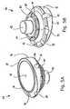
- proximal and distal perspective views respectively, of an articulating liner 38 for fitting to humeral stem 36are shown, including a body 76 which may be formed of a single, integral piece of ultra high molecular weight polyethylene ("UHMWPE"), for example.
- UHMWPEultra high molecular weight polyethylene
- the proximal end of articulating liner 38includes a convex articulating surface 78 for articulating against glenosphere 42 ( Fig. 1 ) of glenoid component 34.
- the distal end of articulating liner 38includes a plurality of spring fingers 80 spaced therearound and a post 82 which may be non-tapered to provide an interference fit within tapered bore 60 of humeral stem 36.
- Articulating liner 38further includes a plurality of recesses 84 disposed about the outer periphery of body 76 for providing clearance for accessing suture holes 66 of humeral stem 36 when articulating liner 38 is attached to humeral stem 36 in the manner described below.
- articulating liner 38is attachable to humeral stem 36 by using an impaction instrument (not shown) which may include a first portion fitting within the cavity defined by articulating surface 78 and a second, prong-type portion insertable through notch 86 in the outer periphery of body 76 of articulating liner 38 and through the bore of instrument seat 64 of humeral stem 36 to rotationally locate articulating liner 38 with respect to humeral stem 36, with post 82 of articulating liner 38 received within tapered bore 60 of humeral stem 36 by an interference fit.
- an impaction instrument(not shown) which may include a first portion fitting within the cavity defined by articulating surface 78 and a second, prong-type portion insertable through notch 86 in the outer periphery of body 76 of articulating liner 38 and through the bore of instrument seat 64 of humeral stem 36 to rotationally locate articulating liner 38 with respect to humeral stem 36, with post 82 of articulating liner 38
- articulating liner 38is impacted into internal cavity 54 of humeral stem 36 until spring fingers 80 of articulating liner 38 resiliently engage behind annular rib 58 of humeral stem 36 to thereby axially lock articulating liner 38 with respect to humeral stem 36, with rotation of articulating liner 38 with respect to humeral stem 36 prevented by the engagement of instrument seat 64 of humeral stem 36 within notch 86 of articulating liner 38.
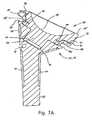
- articulating liner 38is substantially wedge-shaped, having an annular lower surface 83 in abutment with outer rim 62 of head portion 50 of humeral stem 36 as shown in Figs. 7B and 7C , and an annular upper surface 85 opposite lower surface 83.
- lower and upper surfaces 83 and 85together define an angle ⁇ therebetween in a medial/lateral plane which may be as small as about 1 or 5 degrees, or may be as large as about 15, 30, or 35 degrees, or may be sized at any one degree increment therebetween, for example.
- a first articulating liner 38adefines an angle ⁇ of about 7 degrees and, in the embodiment of Fig. 7C , a second articulating liner 38b defines an angle ⁇ of about 12 degrees. Further details of first and second articulating liners 38a and 38b are discussed below.
- the upper surface 85 of the articulating linerdefines a second neck angle ⁇ with respect to longitudinal axis L 1 -L 1 of humeral stem 36 or, stated another way, the first neck angle a, between longitudinal axis L 1 -L 1 of humeral stem 36 and outer rim 62 along resection cut line L 2 -L 2 , and the angle y of articulating liner 38 combine to define second neck angle ⁇ .
- second neck angle ⁇is in a medial/lateral plane.
- Second neck angle ⁇may be as small as about 55 or 60 degrees, or may be as large as about 65 or 70 degrees when humeral stem 36 is configured for a "reverse" shoulder arthroplasty, and the articulating liner 38 may be selected from a plurality of articulating liners 38 having varying angles ⁇ to provide proper stability for the shoulder joint.
- second neck angle ⁇is about 60 degrees and in the embodiment of Fig. 7C second neck angle ⁇ is about 65 degrees.
- Articulating liner 38may be selected by a surgeon from a plurality of differently-sized articulating liners, having varying size diameters and heights, for example, to provide a properly sized articulating liner for a given patient anatomy and/or joint reconstruction need. Additionally, a plurality of trial or provisional articulating liners (not shown) may be provided with the present implant system, which lack spring fingers 80 and/or post 82 but otherwise are substantially identical to the implanted articulating liner 38. In this manner, a surgeon may use such provisional articulating liners during the arthroplasty procedure to determine the correct size of articulating liner to be implanted, followed by selecting the desired articulating liner and securing same to humeral stem 36 in the manner described above.
- articulating liner 38ahas an articulating surface 78a with a diameter D 1 of 36 mm
- articulating liner 38bhas an articulating surface 78b with a diameter D 2 of 40 mm.
- the diameters of the articulating liners 38may be as small as about 30 mm, 32 mm, or 34 mm, or may be as large about 50 mm, 55 mm, or 60 mm, or may be sized at any one degree increment therebetween, for example.
- Articulating liner 38amay typically be used in most patients; however, articulating liner 38b may be used in relatively larger patients, or in other cases where a greater diameter articulating surface may be desired such as, for example to provide greater joint stability.
- a surgeonmay intraoperatively select an appropriate articulating liner from articulating liner 38a, articulating liner 38b, or an articulating liner having a differently sized or differently dimensioned articulating surface (not shown) based on the anatomical needs of a particular patient.
- a series of articulating linersmay be provided, having varying articulating surface diameters or other dimensions, which are compatible with humeral stem 36.
- spacers 90may be used to provide increased tension on the shoulder joint when needed in the event that the height of articulating liner 38 is not sufficient to provide such tension.
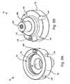
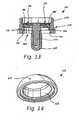
- a spacer 90proximal and distal perspective views, respectively, of a spacer 90 are shown, including a body 92 which may be formed of titanium, for example.
- the proximal end of spacer 90includes internal cavity 94 having an annular rib 96 and a bore 98 which dimensionally replicate the internal cavity 54 of humeral stem 36 and in particular, the annular rib 58 and bore 60 of humeral stem 36, described above.
- spacer 90includes instrument seat 100 replicating instrument seat 64 of humeral stem 36, described above.
- the distal end of spacer 90includes tapered stem 102 for lockably fitting within tapered bore 60 of humeral stem 36.
- Body 92 of spacer 90includes a plurality of recesses 104 disposed about an outer periphery thereof for providing clearance for accessing suture holes 66 of humeral stem 36 when spacer 90 is attached to humeral stem 36 in the manner described below.
- spacer 90may be fitted to humeral stem 36 using a suitable instrument (not shown) in substantially the same manner as articulating liner 38 described above, with tapered stem 102 of spacer 90 providing a tapered lock fit within tapered bore 60 of humeral stem 36, and with relative rotation between spacer 90 and humeral stem 36 prevented by engagement of instrument seat 64 of humeral stem 36 within notch 106 ( Fig. 8B ) of spacer 90 disposed opposite seat 100 of spacer 90.
- a selected articulating liner 38may be attached within internal cavity 94 of spacer 90 in the same manner as that described above with respect to the attachment of articulating liner 38 to humeral stem 36, namely, by engaging spring fingers 80 of articulating liner 38 with annular rib 96 of spacer 90 and receipt of post 82 of articulating liner 38 within bore 98 of spacer 90.
- Spacer 90also includes a threaded central bore 108 that may be used for threading receipt of a threaded end of a retrieval instrument (not shown) used to remove spacer 90 from humeral stem 36 whereby, upon threading of the threaded end of the retrieval instrument through threaded bore 108, the threaded end will bottom out against the bottom of tapered bore 60 of humeral stem 36 to disengage spacer 90 from humeral stem 36.
- a threaded central bore 108may be used for threading receipt of a threaded end of a retrieval instrument (not shown) used to remove spacer 90 from humeral stem 36 whereby, upon threading of the threaded end of the retrieval instrument through threaded bore 108, the threaded end will bottom out against the bottom of tapered bore 60 of humeral stem 36 to disengage spacer 90 from humeral stem 36.
- the articulating liners of the present shoulder implant systemmay also include an anteversion or retroversion feature.
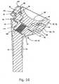
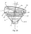
- a further embodiment of an articulating lineris shown, which are each angled in an anterior/posterior plane with respect to the longitudinal axis L 1 -L 1 of humeral stem 36 to provide anteversion or retroversion.
- an articulating liner 38cis shown attached to humeral stem 36 which, except as described below, is identical to articulating liner 38 described above.
- Body 76 of articulating liner 38cincludes a concave articulating surface 78c which is oriented at an angle A in an anterior/posterior plane with respect to longitudinal axis L 1 -L 1 of humeral stem 36.
- a line L 3 -L 3which is perpendicular to articulating surface 78c and passes through the center thereof, defines angle A with respect to longitudinal axis L 1 -L 1 of humeral stem 36.
- Angle ⁇may define an anterior-facing orientation of articulating surface 78c for anteversion or, as shown in Fig. 19 , angle A may define a posterior-facing orientation of articulating surface 78c for retroversion.
- Angle Amay be as small as about 1, 5, or 10 degrees, or may as large as about 20, 25, or 30 degrees, or may be sized at any one degree increment therebetween, for example. In the embodiment of Fig. 19 , angle A is about 20 degrees. Additionally, as shown in Fig.
- the articulating liners 38 disclosed hereinmay include both the foregoing anteversion or retroversion angle ⁇ in an anterior/posterior plane with respect to longitudinal axis L 1 -L 1 of humeral stem 36, as well as the above-described angle ⁇ in a medial/lateral plane with respect to the longitudinal axis L 1 -L 1 of humeral stem 36.
- articulating liner 38ccan be used to provide anteversion or retroversion in a "reverse" total shoulder arthroplasty.
- humeral stem 36provides a humeral component which serves as a universal humeral implant platform that may be used with the various modular components in the manner described above to configure humeral stem 36 for use in a "reverse" total shoulder arthroplasty.
- the humeral stem 36may be configured for a "reverse" total shoulder arthroplasty as shown in Figs. 1 and 5A-10 , according to patient needs by using the components described above.
- humeral stem 36may remain implanted throughout any necessary revision procedures, allowing a surgeon to perform any revisions as needed by replacing one more of the various modular components described above without the need to replace humeral stem 36 itself.
- humeral stem 36lies substantially along the resection cut line L 2 -L 2 of the resected humerus as discussed above.
- the various modular components disclosed hereinmay be attached, removed, and/or replaced onto the implanted humeral stem 36 above the resection cut line L 2 -L 2 without the need for removing bone around the proximal humerus H and/or replacing or modifying the location of the implanted humeral stem 36 in the humerus H.
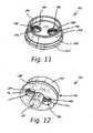
- glenoid component 34( Fig. 18 ) is shown, which generally includes a glenoid base 40, shown in Figs. 11-13 and 18 , and glenosphere 42, shown in Figs. 14 and 18 .
- glenoid base 40includes a body 130 which may be made of a suitable biocompatible metal such as titanium, for example, and includes stem portion 132 ( Fig. 13 ) projecting from a medial side thereof, and a tapered annular wall 134 projecting from a lateral side thereof.
- the medial side of body 130 of glenoid base 40, including stem portion 132,may include a pad or coating portion 135 of the highly porous biomaterial described above, produced using Trabecular MetalTM technology available from Zimmer, Inc., of Warsaw, Indiana, to promote bone ingrowth from the glenoid into and around glenoid base 40 to thereby osseointegrate glenoid base 40 with the glenoid.
- the glenoidis prepared for attachment of glenoid component 34 by preparing a bore in the glenoid for receipt of stem portion 132 of glenoid body 130, and by reaming the glenoid with a reamer (not shown) to prepare a substantially flat, planar surface on the glenoid to which the substantially flat, planar medial side of body 130 may be fitted, as described below.
- Body 130 of glenoid base 40includes a pair of bores 136 therethrough which, as best shown in Fig. 13 , include first, threaded portions 138 and second portions 140 which are tapered to open outwardly toward the medial side of glenoid base 40.
- Bores 136additionally include screw head seats 142 located between first and second portions 138 and 140 of bores 136. As shown, screw head seats 142 have an at least partially spherical shape, but may also have an angled or tapered profile.
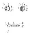
- a pair of polyaxial screws 144are provided, shown in Fig.
- Screw locks 152shown in Figs. 16 and 17 , are also provided which, as described below, cooperate with threaded portions 138 of bores 136 and with heads 146 of screws 144 to lock the positions of screws 144.
- Each screw lock 152generally includes an external thread 154, a semi-spherical concave seat 156, and instrument engagement structure such as a polygonal fitting 158.
- glenoid base 40is shown with a screw 144 and screw head lock 152 in a locked position on the left and a screw 144 and screw head lock 152 in an unlocked position on the right.
- each screw 144is inserted using a suitable instrument (not shown) through a respective bore 136 in body 130 and is threaded into a pre-tapped bore in the glenoid.
- Tapered second portions 140 of bores 136accommodate polyaxial positioning of screws 144 up to an angle of 30° from the longitudinal axis of glenoid base 40 as defined along stem portion 132 thereof.
- glenoid base 40to accommodate polyaxial positioning of screws 144 allows the surgeon to determine optimum angles of screws 144 needed to conform to the anatomy of the patient and/or to most effectively take advantage of available bone stock to anchor glenoid base 40 to the glenoid.
- screw locks 152are threaded into threaded first portions 138 of bores 136 using a suitable instrument (not shown) to firmly engage seats 156 of screw head locks 152 against heads 146 of screws 144, thereby firmly pressing screw heads 146 against seats 142 within bores 136 to locking screw heads 146 in a selected fixed position and in turn to fix the positions of screws 144 with respect to glenoid base 40.
- glenoid base 40may include a substantially planar medial side 160, with tapered second portions 140 of bores 136 accommodating polyaxial positioning of screws 144.
- planar medial side 160 of glenoid base 40allows glenoid base 40 to be seated against a planar surface of the glenoid which may be prepared with a planar reamer (not shown), and eliminates the need for boss portions or other protuberances projecting from the medial side of glenoid base 40 to accommodate polyaxial positioning of screws 144, which would require additional glenoid preparation steps to accommodate.
- glenosphere 42generally includes a medial side having a tapered interior bore 162 extending therein, which may be aligned with a longitudinal axis of glenosphere 42 or may be offset with respect to the longitudinal axis of glenosphere 42.
- Glenosphere 42additionally includes a lateral side having a convex articulating surface 164.
- Glenosphere 42may be provided in a variety of different sizes, such as with varying diameters, varying heights, and varying offsets for internal bore 162 to enable a surgeon to select an optimal glenosphere needed for the anatomy of a particular patient.
- the glenosphereis fitted onto glenoid base 40 by lockingly fitting tapered bore 162 of glenosphere 42 onto the cooperatively tapered annular wall 134 of glenoid base 40.
- the foregoing attachment between bore 162 of glenosphere 42 and annular wall 134 of glenoid base 40allows glenosphere 42 to have a substantially smooth, uninterrupted articulating surface 164 which lacks an opening therein for receipt of a fastener, for example.
Landscapes
- Health & Medical Sciences (AREA)
- Orthopedic Medicine & Surgery (AREA)
- Cardiology (AREA)
- Oral & Maxillofacial Surgery (AREA)
- Transplantation (AREA)
- Engineering & Computer Science (AREA)
- Biomedical Technology (AREA)
- Heart & Thoracic Surgery (AREA)
- Vascular Medicine (AREA)
- Life Sciences & Earth Sciences (AREA)
- Animal Behavior & Ethology (AREA)
- General Health & Medical Sciences (AREA)
- Public Health (AREA)
- Veterinary Medicine (AREA)
- Prostheses (AREA)
Description
- The present invention relates to surgical implant systems, and particularly implants for a "reverse" total shoulder arthroplasty.
- In a healthy shoulder, the proximal humerus is generally ball-shaped, and articulates within a socket formed by the scapula, called the glenoid, to form the shoulder joint. Conventional implant systems for the total replacement of the shoulder joint due to disease or trauma,i.e., a total shoulder arthroplasty, generally replicate the natural anatomy of the shoulder, and typically include a humeral component having a stem which fits within the humeral canal, and an articulating head which articulates within the socket of a glenoid component implanted within the glenoid of the scapula. An implant system for the replacement of only the humeral component of the shoulder joint, i.e., a hemi shoulder arthroplasty, typically includes only a humeral component which articulates within the natural glenoid socket of the scapula.
FR2699400 EP1543801 discloses a prosthesis comprising an intermediate component provided with a retaining unit for retaining a femoral component in a position where a pad is in support against convex surface of the intermediate component The unit defines an opening within which the neck of the femoral component may be movedEP1004283 discloses an orthopaedic prosthesis system for replacement of an articulating portion of a long bone including a sleeve, a stem, and a neck The sleeve has an outer bone engagement surface and include opposed proximal and distal female taper regions The stem has a distal end for fixation within a long bone and a proximal end including a male taper region engaged with the distal female taper of the sleeve. The neck has a taper post that engages the proximal taper of the sleeve Both the neck and the sleeve may define axial bores, the axial bore in the sleeve communicating with and being generally coaxial with the two opposed female tapers, and the neck axial bore extending through the taper post.EP0679375 discloses a prosthesis assembly consisting of a range of humeral shanks each fitted at the metaphysis end with an interchangeable and adjustable index unit which allows for adjustable humeral retro-torsion. Each of the index units is able to receive a range of humeral heads designed to co-operate with a glenoid component, which can also be in a range of sizes.- Recently, "reverse" type implant systems have been developed in which the conventional ball-and-socket configuration that replicates the natural anatomy of the shoulder is reversed, such that a concave recessed articulating component is provided at the proximal end of the humeral component that articulates against a convex portion of the glenoid component. Such reverse shoulder implant systems are thought to provide an increased range of motion for treatment of glenohumeral arthritis associated with irreparable rotator cuff damage, for example, by moving the center of rotation between the humeral component and the glenoid component to allow the deltoid muscles to exert a greater lever arm on the humerus.
- The present invention provides an implant system for reverse total shoulder arthroplasties, including a humeral stem having an enlarged head portion with interfaces adapted to removably receive various modular interchangeable components, such as articulating liners and spacers. The humeral stem functions as a universal platform that may be used in "reverse" total shoulder arthroplasties. The articulating liner articulates against a glenoid component, and may be angled to change the neck angle of the humeral stem from an angle suited for a conventional total arthroplasty or a hemi arthroplasty to an angle suited for a "reverse" total arthroplasty. The spacer may optionally be used to fit between the humeral stem and the articulating liner to provide increased joint tension when needed. A glenoid component is also provided which is mountable to the glenoid by a plurality of polyaxial locking screws, and which receives a glenosphere having a smooth, convex and uninterrupted articulating surface against which the articulating liner of the humeral component may articulate.
- In one form thereof, the present invention provides. A humeral implant component (32) for use in a reverse total shoulder arthroplasty, comprising:
- a stem (36) that includes a stem portion (52) extending toward a distal end (48) of the stem and a head portion (50) at a proximal end (46) of the stem, said head portion including an internal cavity (54) having an engagement structure (58) and a first tapered bore (60); and
- an articulating liner (38) receivable within said internal cavity and including a stem (82) receivable within said first tapered bore and an engagement structure (80) engageable with said head portion engagement structure to axially secure said articulating liner to said head portion when said articulating liner stem is received within said first tapered bore, said articulating liner being substantially wedge-shaped with an annular lower surface (83) opposite an annular upper surface (85) and with a concave articulating surface (78) extending from said annular upper surface toward said articulating liner stem for articulating against a convex surface of a glenoid component, said annular upper surface defining an angle (β) with respect to a longitudinal axis (L1) of said stem portion, said angle being between about 55 degrees and about 70 degrees.
- The above-mentioned and other features and advantages of this invention, and the manner of attaining them, will become more apparent and the invention itself will be better understood by reference to the following description of embodiments of the invention taken in conjunction with the accompanying drawings, wherein:
Fig. 1 is a perspective view of a "reverse total shoulder arthroplasty implant system according to the present invention, including a humeral component and a glenoid component;Fig. 2 is a side view of the humeral stem through a medial/lateral plane, further showing an outline of the humerus;Fig. 3 is a perspective view of the proximal end of the humeral stem;Fig. 4 is a sectional view through a medial/lateral plane, showing the proximal end of the humeral stem;Fig. 5A is a perspective view of the proximal end of an articulating liner;Fig. 5B is a perspective view of the distal end of the articulating liner ofFig. 6A ;Fig. 6 is an exploded view of the humeral stem and articulating liner;Fig. 7A is a partial sectional view through a medial/lateral plane, showing the connection between the humeral stem and an articulating liner;Fig. 7B is a partial sectional view through a medial/lateral plane, showing the connection between the humeral stem and the articulating liner ofFig. 7 ;Fig. 7C is a partial sectional view through a medial/lateral plane, showing the connection between the humeral stem and a second articulating liner;Fig.8A is a perspective view of the proximal end of a spacer;Fig. 8B is a perspective view of the distal end of the spacer ofFig. 9A ;Fig. 9 is an exploded view of the humeral stem and a spacer;Fig. 10 is a partial sectional view through a medial/lateral plane, showing the connection between the humeral stem and the spacer ofFig. 10 , and further showing the connection between the spacer and an articulating liner;Fig. 11 is a perspective view of the lateral side of a glenoid base;Fig. 12 is a perspective view of the medial side of the glenoid base;Fig. 13 is a sectional view of the glenoid base;Fig. 14 is a perspective view of the medial side of the glenosphere;Fig. 15 is a perspective view of a screw;Fig. 16 is a first perspective view of a screw lock;Fig. 17 is a second perspective view of a screw lock;Fig. 18 is a sectional view through the glenoid component, showing connection between the glenoid base, screws, and glenosphere, and further showing a screw and a screw head lock in a locked position on the left and a screw and a screw head lock in an unlocked position on the right;Fig. 19 is partial sectional view through an anterior/posterior plane, showing the connection between the humeral stem and an articulating liner according to a further embodiment; and- Corresponding reference characters indicate corresponding parts throughout the several views. The exemplifications set out herein illustrate exemplary embodiments of the invention, and such exemplifications are not to be construed as limiting the scope of the invention any manner.
- As used herein, the following directional definitions apply. Anterior and posterior mean nearer the front or nearer the rear of the body, respectively, proximal and distal mean nearer to or further from the root of a structure, respectively, and medial and lateral mean nearer the sagittal plane or further from the sagittal plane, respectively. The sagittal plane is an imaginary vertical plane through the middle of the body that divides the body into right and left halves.
- Referring to
Fig. 1 , implant system 30a for a "reverse" total shoulder arthroplasty is shown, which generally includes ahumeral component 32 adapted to be fitted within a prepared proximal end and canal of a humerus, and aglenoid component 34 mounted to a prepared surface of the glenoid via a plurality of screws, wherein thehumeral component 32 articulates about theglenoid component 34 to replicate the movement of the natural shoulder joint. As described in further detail below,humeral component 32 generally includeshumeral stem 36 and articulatingliner 38 fitted tohumeral stem 36 and having a concave articulating surface, andglenoid component 34 generally includes aglenoid base 40 and aglenosphere 42 fitted toglenoid base 40 and having a convex articulating surface, wherein articulatingliner 38 articulates aboutglenosphere 42. - Referring to
Figs. 2-4 ,humeral stem 36 is shown, havingproximal end 46 anddistal end 48.Humeral stem 36 includeshead portion 50 atproximal end 46 andstem portion 52 extending towarddistal end 48. In the embodiment shown inFigs. 2-4 ,head portion 50 andstem portion 52 are unitarily formed as a single piece; however,head portion 50 andstem portion 52 may also be formed of separate components joined to one another.Humeral stem 36, as well as the other implant components described herein, may be made of a suitable biocompatible metal, such as titanium, for example, or from other materials as described below.Head portion 50 ofhumeral stem 36 is substantially enlarged with respect to stemportion 52, and flares outwardly fromstem portion 52 in shape towardsproximal end 46 ofhumeral stem 36. As may be seen fromFig. 2 , after the proximal end of the humerus is resected and the humeral canal and proximal humeral end are prepared using known instruments (not shown) and methods,stem portion 52 is received in the prepared canal of the humerus, andhead portion 50 is received within a conically reamed portion of the proximal end of the resected humerus. - As shown in
Figs. 3 and4 ,head portion 50 includes aninternal cavity 54 extending into the proximal end thereof, including a first, relativelylarger diameter portion 56 with anannular rib 58 and a second, relatively smaller diameter portion defining atapered bore 60. An annular,outer rim 62 is formed about theproximal end 46 ofhead portion 50 and includes aninstrument seat 64 with a central bore which may be used to anchor and locate an impaction instrument (not shown) for impactinghumeral stem 36 into a reamed and prepared canal in the humerus. A plurality of suture holes 66 are defined inouter rim 62 and, as shown inFigs. 2 and4 , asuture groove 68 is disposed beneath and adjacentouter rim 62, the functions of which will be described below. Humeral stem 36 additionally includes, toward theproximal end 46 thereof, a plurality of recessed portions, best seen inFig. 4 , in which are disposed pads orcoating portions 70 of a highly porous biomaterial useful as a bone substitute and/or cell and tissue receptive material for promotion of bone ingrowth to aid in the osseointegration ofhumeral stem 36 within the humerus. An example of such a material is produced using Trabecular Metal™ technology available from Zimmer, Inc., of Warsaw, Indiana. Trabecular Metal™ is a trademark of Zimmer Technology, Inc. Such a material may be formed from a reticulated vitreous carbon foam substrate which is infiltrated and coated with a biocompatible metal, such as tantalum, etc., by a chemical vapor deposition ("CVD") process in the manner disclosed in detail inU.S. Patent No. 5,282,861 . As would be apparent to one skilled in the art, although the embodiments described herein utilize porous tantalum, other metals such as niobium, or alloys of tantalum and niobium with one another or with other metals may also be used.- Referring to
Figs. 2 and4 ,head portion 50 ofhumeral stem 36 additionally includes ahub section 72 of titanium on a lateral side thereof having asuture hole 74 through which sutures may be threaded to aid in reducing humeral fractures as needed. Suture holes 66 andsuture groove 68 ofhead portion 50 ofhumeral stem 36 may also be used by a surgeon to reconstruct the proximal humerus in the event of humeral fractures, or for the attachment of soft tissue. For example, one or more of suture holes 66 may be used to anchor sutures wrapped around bone fragments of the upper humerus usingsuture groove 68, for example, to bring the lesser and greater tuberosities into reduction circumferentially abouthumeral stem 36, or to attach soft tissue circumferentially abouthumeral stem 36. Also, a surgeon may selectively use one, two, three or all of suture holes 66 alone or in combination with each other and withsuture groove 68 as needed for this purpose. Additionally, the axial clearance beneathouter rim 62 ofhumeral stem 36 provided bysuture groove 68 allows the surgeon to use one or more of suture holes 66 for "pull down" sutures to pull bone fragments along the axial direction ofhumeral stem 36 for reduction of fractures or for attachment of soft tissue, for example. - Referring to
Fig. 2 ,outer rim 62 at the proximal end ofhead portion 50 ofhumeral stem 36 defines a substantially flat or planar surface which, as shown, is disposed substantially along a resection cut line L2-L2 along which a surgeon makes a resection cut to resect the proximal humerus H whenhumeral stem 36 is implanted during a total or hemi shoulder arthroplasty. A first neck angle a is defined in a medial/lateral plane between the surface ofouter rim 62 along resection cut line L2-L2, and the longitudinal axis L1-L1 ofhumeral stem 36. Neck angle α may be as little as about 35, 40, or 45 degrees, and may be as great as about 50 or 55 degrees whenhumeral stem 36 is used in a conventional shoulder arthroplasty or in a hemi arthroplasty, as described below (not part of the invention). In the embodiment ofFigs. 2 and inFigs. 7B and7C discussed below, neck angle a is about 53 degrees. Further, as also described below, an articulating liner may be used to provide a greater neck angle with respect to longitudinal axis L1-L1 ofhumeral stem 36 which is more suited to a "reverse" shoulder arthroplasty. - Referring to
Figs. 5A and 5B , proximal and distal perspective views respectively, of an articulatingliner 38 for fitting tohumeral stem 36 are shown, including abody 76 which may be formed of a single, integral piece of ultra high molecular weight polyethylene ("UHMWPE"), for example. The proximal end of articulatingliner 38 includes a convex articulatingsurface 78 for articulating against glenosphere 42 (Fig. 1 ) ofglenoid component 34. The distal end of articulatingliner 38 includes a plurality ofspring fingers 80 spaced therearound and apost 82 which may be non-tapered to provide an interference fit within tapered bore 60 ofhumeral stem 36. Articulatingliner 38 further includes a plurality ofrecesses 84 disposed about the outer periphery ofbody 76 for providing clearance for accessingsuture holes 66 ofhumeral stem 36 when articulatingliner 38 is attached tohumeral stem 36 in the manner described below. - Referring additionally to
Figs. 6 and7 , articulatingliner 38 is attachable tohumeral stem 36 by using an impaction instrument (not shown) which may include a first portion fitting within the cavity defined by articulatingsurface 78 and a second, prong-type portion insertable throughnotch 86 in the outer periphery ofbody 76 of articulatingliner 38 and through the bore ofinstrument seat 64 ofhumeral stem 36 to rotationally locate articulatingliner 38 with respect tohumeral stem 36, withpost 82 of articulatingliner 38 received within tapered bore 60 ofhumeral stem 36 by an interference fit. Thereafter, articulatingliner 38 is impacted intointernal cavity 54 ofhumeral stem 36 untilspring fingers 80 of articulatingliner 38 resiliently engage behindannular rib 58 ofhumeral stem 36 to thereby axiallylock articulating liner 38 with respect tohumeral stem 36, with rotation of articulatingliner 38 with respect tohumeral stem 36 prevented by the engagement ofinstrument seat 64 ofhumeral stem 36 withinnotch 86 of articulatingliner 38. - As shown in
Figs. 5A-7C , articulatingliner 38 is substantially wedge-shaped, having an annularlower surface 83 in abutment withouter rim 62 ofhead portion 50 ofhumeral stem 36 as shown inFigs. 7B and7C , and an annularupper surface 85 oppositelower surface 83. As shown inFigs. 7B and7C , lower andupper surfaces Fig. 7B , a first articulatingliner 38a defines an angle γ of about 7 degrees and, in the embodiment ofFig. 7C , a second articulating liner 38b defines an angle γ of about 12 degrees. Further details of first and second articulatingliners 38a and 38b are discussed below. When an articulatingliner 38a or 38b is secured to headportion 50 ofhumeral stem 36 in the manner described above, theupper surface 85 of the articulating liner defines a second neck angle β with respect to longitudinal axis L1-L1 ofhumeral stem 36 or, stated another way, the first neck angle a, between longitudinal axis L1-L1 ofhumeral stem 36 andouter rim 62 along resection cut line L2-L2, and the angle y of articulatingliner 38 combine to define second neck angle β. As with first neck angle α and angle γ of articulatingliner 38, second neck angle β is in a medial/lateral plane. Second neck angle β may be as small as about 55 or 60 degrees, or may be as large as about 65 or 70 degrees whenhumeral stem 36 is configured for a "reverse" shoulder arthroplasty, and the articulatingliner 38 may be selected from a plurality of articulatingliners 38 having varying angles γ to provide proper stability for the shoulder joint. In the embodiment ofFig. 7B , second neck angle β is about 60 degrees and in the embodiment ofFig. 7C second neck angle β is about 65 degrees. - Articulating
liner 38 may be selected by a surgeon from a plurality of differently-sized articulating liners, having varying size diameters and heights, for example, to provide a properly sized articulating liner for a given patient anatomy and/or joint reconstruction need. Additionally, a plurality of trial or provisional articulating liners (not shown) may be provided with the present implant system, which lackspring fingers 80 and/or post 82 but otherwise are substantially identical to the implanted articulatingliner 38. In this manner, a surgeon may use such provisional articulating liners during the arthroplasty procedure to determine the correct size of articulating liner to be implanted, followed by selecting the desired articulating liner and securing same tohumeral stem 36 in the manner described above. - Referring to
Figs. 7B and7C , two differently-sized articulatingliners 38a and 38b are shown, which are structurally identical except for the diameter of articulating surfaces 78a and 78b thereof. In one embodiment, articulatingliner 38a has an articulating surface 78a with a diameter D1 of 36 mm, and articulating liner 38b has an articulating surface 78b with a diameter D2 of 40 mm. However, the diameters of the articulatingliners 38 may be as small as about 30 mm, 32 mm, or 34 mm, or may be as large about 50 mm, 55 mm, or 60 mm, or may be sized at any one degree increment therebetween, for example. Articulatingliner 38a may typically be used in most patients; however, articulating liner 38b may be used in relatively larger patients, or in other cases where a greater diameter articulating surface may be desired such as, for example to provide greater joint stability. Advantageously, because the above-described structure by which articulatingliners 38a and 38b are secured to headportion 50 ofhumeral stem 36 is identical, a surgeon may intraoperatively select an appropriate articulating liner from articulatingliner 38a, articulating liner 38b, or an articulating liner having a differently sized or differently dimensioned articulating surface (not shown) based on the anatomical needs of a particular patient. Thus, a series of articulating liners may be provided, having varying articulating surface diameters or other dimensions, which are compatible withhumeral stem 36. - Optionally, spacers 90 (
Figs. 8A-10 ) of various size, described below, may be used to provide increased tension on the shoulder joint when needed in the event that the height of articulatingliner 38 is not sufficient to provide such tension. Referring toFigs. 8A and 8B , proximal and distal perspective views, respectively, of aspacer 90 are shown, including abody 92 which may be formed of titanium, for example. The proximal end ofspacer 90 includesinternal cavity 94 having anannular rib 96 and abore 98 which dimensionally replicate theinternal cavity 54 ofhumeral stem 36 and in particular, theannular rib 58 and bore 60 ofhumeral stem 36, described above. Additionally,spacer 90 includesinstrument seat 100 replicatinginstrument seat 64 ofhumeral stem 36, described above. The distal end ofspacer 90 includes taperedstem 102 for lockably fitting within tapered bore 60 ofhumeral stem 36.Body 92 ofspacer 90 includes a plurality ofrecesses 104 disposed about an outer periphery thereof for providing clearance for accessingsuture holes 66 ofhumeral stem 36 whenspacer 90 is attached tohumeral stem 36 in the manner described below. - In use, referring additionally to
Figs. 9 and10 ,spacer 90 may be fitted tohumeral stem 36 using a suitable instrument (not shown) in substantially the same manner as articulatingliner 38 described above, withtapered stem 102 ofspacer 90 providing a tapered lock fit within tapered bore 60 ofhumeral stem 36, and with relative rotation betweenspacer 90 andhumeral stem 36 prevented by engagement ofinstrument seat 64 ofhumeral stem 36 within notch 106 (Fig. 8B ) ofspacer 90 disposed oppositeseat 100 ofspacer 90. Thereafter, a selected articulatingliner 38 may be attached withininternal cavity 94 ofspacer 90 in the same manner as that described above with respect to the attachment of articulatingliner 38 tohumeral stem 36, namely, by engagingspring fingers 80 of articulatingliner 38 withannular rib 96 ofspacer 90 and receipt ofpost 82 of articulatingliner 38 withinbore 98 ofspacer 90.Spacer 90 also includes a threadedcentral bore 108 that may be used for threading receipt of a threaded end of a retrieval instrument (not shown) used to removespacer 90 fromhumeral stem 36 whereby, upon threading of the threaded end of the retrieval instrument through threadedbore 108, the threaded end will bottom out against the bottom of tapered bore 60 ofhumeral stem 36 to disengagespacer 90 fromhumeral stem 36. - As discussed below, the articulating liners of the present shoulder implant system may also include an anteversion or retroversion feature. Referring to
Fig. 19 a further embodiment of an articulating liner is shown, which are each angled in an anterior/posterior plane with respect to the longitudinal axis L1-L1 ofhumeral stem 36 to provide anteversion or retroversion. - Referring to
Fig. 19 , an articulating liner 38c is shown attached tohumeral stem 36 which, except as described below, is identical to articulatingliner 38 described above.Body 76 of articulating liner 38c includes a concave articulating surface 78c which is oriented at an angle A in an anterior/posterior plane with respect to longitudinal axis L1-L1 ofhumeral stem 36. Specifically, a line L3-L3, which is perpendicular to articulating surface 78c and passes through the center thereof, defines angle A with respect to longitudinal axis L1-L1 ofhumeral stem 36. Angle Δ may define an anterior-facing orientation of articulating surface 78c for anteversion or, as shown inFig. 19 , angle A may define a posterior-facing orientation of articulating surface 78c for retroversion. Angle A may be as small as about 1, 5, or 10 degrees, or may as large as about 20, 25, or 30 degrees, or may be sized at any one degree increment therebetween, for example. In the embodiment ofFig. 19 , angle A is about 20 degrees. Additionally, as shown inFig. 19 , the articulatingliners 38 disclosed herein may include both the foregoing anteversion or retroversion angle Δ in an anterior/posterior plane with respect to longitudinal axis L1-L1 ofhumeral stem 36, as well as the above-described angle γ in a medial/lateral plane with respect to the longitudinal axis L1-L1 ofhumeral stem 36. In this manner, articulating liner 38c can be used to provide anteversion or retroversion in a "reverse" total shoulder arthroplasty. - Advantageously,
humeral stem 36 provides a humeral component which serves as a universal humeral implant platform that may be used with the various modular components in the manner described above to configurehumeral stem 36 for use in a "reverse" total shoulder arthroplasty. Thus, once thehumeral stem 36 is implanted within the proximal humerus as shown inFig. 2 , thehumeral stem 36 may be configured for a "reverse" total shoulder arthroplasty as shown inFigs. 1 and5A-10 , according to patient needs by using the components described above. - Also, once implanted,
humeral stem 36 may remain implanted throughout any necessary revision procedures, allowing a surgeon to perform any revisions as needed by replacing one more of the various modular components described above without the need to replacehumeral stem 36 itself. - One particular advantage of
humeral stem 36 is that the proximal surface thereof lies substantially along the resection cut line L2-L2 of the resected humerus as discussed above. Thus, the various modular components disclosed herein may be attached, removed, and/or replaced onto the implantedhumeral stem 36 above the resection cut line L2-L2 without the need for removing bone around the proximal humerus H and/or replacing or modifying the location of the implantedhumeral stem 36 in the humerus H. - Referring to
Figs. 11-18 , glenoid component 34 (Fig. 18 ) is shown, which generally includes aglenoid base 40, shown inFigs. 11-13 and18 , and glenosphere 42, shown inFigs. 14 and18 . Referring toFigs. 11-13 ,glenoid base 40 includes abody 130 which may be made of a suitable biocompatible metal such as titanium, for example, and includes stem portion 132 (Fig. 13 ) projecting from a medial side thereof, and a taperedannular wall 134 projecting from a lateral side thereof. The medial side ofbody 130 ofglenoid base 40, includingstem portion 132, may include a pad orcoating portion 135 of the highly porous biomaterial described above, produced using Trabecular Metal™ technology available from Zimmer, Inc., of Warsaw, Indiana, to promote bone ingrowth from the glenoid into and aroundglenoid base 40 to thereby osseointegrateglenoid base 40 with the glenoid. Typically, the glenoid is prepared for attachment ofglenoid component 34 by preparing a bore in the glenoid for receipt ofstem portion 132 ofglenoid body 130, and by reaming the glenoid with a reamer (not shown) to prepare a substantially flat, planar surface on the glenoid to which the substantially flat, planar medial side ofbody 130 may be fitted, as described below. Body 130 ofglenoid base 40 includes a pair ofbores 136 therethrough which, as best shown inFig. 13 , include first, threadedportions 138 andsecond portions 140 which are tapered to open outwardly toward the medial side ofglenoid base 40.Bores 136 additionally includescrew head seats 142 located between first andsecond portions bores 136. As shown,screw head seats 142 have an at least partially spherical shape, but may also have an angled or tapered profile. To secureglenoid base 40 to the glenoid, a pair ofpolyaxial screws 144 are provided, shown inFig. 15 , each including a substantiallyspherical head 146 with tool engagement structure, such as apolygonal fitting 148, and a threaded shank 150. Screw locks 152, shown inFigs. 16 and 17 , are also provided which, as described below, cooperate with threadedportions 138 ofbores 136 and withheads 146 ofscrews 144 to lock the positions ofscrews 144. Eachscrew lock 152 generally includes anexternal thread 154, a semi-sphericalconcave seat 156, and instrument engagement structure such as apolygonal fitting 158.- Referring to
Fig. 18 ,glenoid base 40 is shown with ascrew 144 and screwhead lock 152 in a locked position on the left and ascrew 144 and screwhead lock 152 in an unlocked position on the right. To secureglenoid base 40 to the prepared glenoid, eachscrew 144 is inserted using a suitable instrument (not shown) through arespective bore 136 inbody 130 and is threaded into a pre-tapped bore in the glenoid. Taperedsecond portions 140 ofbores 136 accommodate polyaxial positioning ofscrews 144 up to an angle of 30° from the longitudinal axis ofglenoid base 40 as defined alongstem portion 132 thereof. Advantageously, the ability ofglenoid base 40 to accommodate polyaxial positioning ofscrews 144 allows the surgeon to determine optimum angles ofscrews 144 needed to conform to the anatomy of the patient and/or to most effectively take advantage of available bone stock to anchorglenoid base 40 to the glenoid. Thereafter, referring to the left offig. 18 , screw locks 152 are threaded into threadedfirst portions 138 ofbores 136 using a suitable instrument (not shown) to firmly engageseats 156 of screw head locks 152 againstheads 146 ofscrews 144, thereby firmly pressing screw heads 146 againstseats 142 withinbores 136 to locking screw heads 146 in a selected fixed position and in turn to fix the positions ofscrews 144 with respect toglenoid base 40. - Advantageously, as may be seen in
Figs. 13 and18 , becausebody 130 ofglenoid base 40 includes taperedsecond portions 140 ofbores 136 to accommodate polyaxial positioning ofscrews 144, withscrew seats 142 recessed into the medial side ofbody 130 ofglenoid base 40,glenoid base 40 may include a substantially planarmedial side 160, with taperedsecond portions 140 ofbores 136 accommodating polyaxial positioning ofscrews 144. The planarmedial side 160 ofglenoid base 40 allowsglenoid base 40 to be seated against a planar surface of the glenoid which may be prepared with a planar reamer (not shown), and eliminates the need for boss portions or other protuberances projecting from the medial side ofglenoid base 40 to accommodate polyaxial positioning ofscrews 144, which would require additional glenoid preparation steps to accommodate. - Referring to
Figs. 14 and18 , glenosphere 42 generally includes a medial side having a taperedinterior bore 162 extending therein, which may be aligned with a longitudinal axis ofglenosphere 42 or may be offset with respect to the longitudinal axis ofglenosphere 42.Glenosphere 42 additionally includes a lateral side having a convex articulatingsurface 164.Glenosphere 42 may be provided in a variety of different sizes, such as with varying diameters, varying heights, and varying offsets forinternal bore 162 to enable a surgeon to select an optimal glenosphere needed for the anatomy of a particular patient. The glenosphere is fitted ontoglenoid base 40 by lockingly fitting tapered bore 162 ofglenosphere 42 onto the cooperatively taperedannular wall 134 ofglenoid base 40. Advantageously, the foregoing attachment betweenbore 162 ofglenosphere 42 andannular wall 134 ofglenoid base 40 allowsglenosphere 42 to have a substantially smooth, uninterrupted articulatingsurface 164 which lacks an opening therein for receipt of a fastener, for example. - While this invention has been described as having a preferred design, the present invention can be further modified within the spirit and scope of this disclosure. This application is therefore intended to cover any variations, uses, or adaptations of the invention using its general principles. Further, this application is intended to cover such departures from the present disclosure as come within known or customary practice in the art to which this invention pertains and which fall within the limits of the appended claims.
Claims (13)
- A humeral implant component (32) for use in a reverse total shoulder arthroplasty, comprising:a stem (36) that includes a stem portion (52) extending toward a distal end (48) of the stem and a head portion (50) at a proximal end (46) of the stem, said head portion including an internal cavity (54) having an engagement structure (58) and a first tapered bore (60); andan articulating liner (38) receivable within said internal cavity and including a stem (82) receivable within said first tapered bore and an engagement structure (80) engageable with said head portion engagement structure to axially secure said articulating liner to said head portion when said articulating liner stem is received within said first tapered bore, said articulating liner being substantially wedge-shaped with an annular lower surface (83) opposite an annular upper surface (85) and with a concave articulating surface (78) extending from said annular upper surface toward said articulating liner stem for articulating against a convex surface of a glenoid component, said annular upper surface defining an angle (β) with respect to a longitudinal axis (L1) of said stem portion, said angle being between about 55 degrees and about 70 degrees.
- The humeral implant component (32) of Claim 1,characterized in that said head portion (50) is substantially enlarged with respect to said stem portion (52).
- The humeral implant component (32) of Claim 1,characterized in that said head portion engagement structure (58) is an annular rib and said articulating liner engagement structure (80) is a plurality of spring fingers.
- The humeral implant component (32) of Claim 1,characterized in that said articulating liner (38) is selected from:a first articulating liner having said articulating liner engagement structure (80) and said concave articulating surface (78) having a diameter of about 36 mm; anda second articulating liner having said articulating liner engagement structure and said concave articulating surface having a diameter of about 40 mm.
- The humeral implant component (32) of Claim 1, further comprising a spacer (90) including an internal cavity (94) having an engagement structure (96) and a second tapered bore (98) on a first side of said spacer, said spacer including a stem (102) opposite said first side of said spacer, said spacer stem receivable within said first tapered bore (60), said spacer engagement structure engageable with said articulating liner engagement structure (80) to axially secure said articulating liner (38) to said spacer when said articulating liner stem (82) is received within said second tapered bore,
said spacer engagement structure dimensionally replicating said head portion engagement structure (58) so that said articulating liner is selectively axially securable to said spacer and said head portion (50),
said first tapered bore of said head portion dimensionally replicating said second tapered bore of said spacer so that said articulating liner stem is receivable within said first tapered bore and said second tapered bore, whereby said spacer is modularly attachable to said head portion and said articulating liner. - The humeral implant component (32) of Claim 5,characterized in that said spacer (90) is selected from a plurality of spacers of varying size dimensions, each said spacer including said spacer engagement structure (96) and said second tapered bore (98).
- The humeral implant component (32) of Claim 1, wherein said angle (β) is between about 60 and about 65 degrees.
- The humeral implant component (32) of Claim 1, wherein said angle (β) is about 60 degrees.
- The humeral implant component (32) of Claim 1, wherein said articulating liner (38) comprises a body (76) formed of a single, integral piece of ultra high molecular weight polyethylene.
- The humeral implant component (32) of Claim 1, wherein said head portion (50) includes a proximal surface (62) that is to lie substantially parallel to a resection cut line of a humerus when said humeral implant component is implanted within a humerus.
- The humeral implant component (32) of Claim 10, wherein said proximal surface (62) defines an angle (α) between about 35 degrees and about 55 degrees with respect to said longitudinal axis (L1) of said stem portion (52).
- The humeral implant component (32) of Claim 11, wherein said annular lower surface (83) is disposable in abutment with said proximal surface (62) when said humeral implant component is implanted within a humerus.
- The humeral implant component (32) of Claim 1, wherein said annular upper surface (85) of said articulating liner (38) also defines one of an anteversion angle and a retroversion angle with respect to said longitudinal axis (L1) of said stem portion (52), said one of an anteversion angle and a retroversion angle between about 1 degree and about 30 degrees.
Priority Applications (2)
| Application Number | Priority Date | Filing Date | Title |
|---|---|---|---|
| EP13184165.2AEP2762107B1 (en) | 2006-01-20 | 2007-01-18 | Shoulder arthroplasty system |
| EP17203965.3AEP3427700A3 (en) | 2006-01-20 | 2007-01-18 | Shoulder arthroplasty system |
Applications Claiming Priority (3)
| Application Number | Priority Date | Filing Date | Title |
|---|---|---|---|
| US76089706P | 2006-01-20 | 2006-01-20 | |
| US80501206P | 2006-06-16 | 2006-06-16 | |
| PCT/US2007/060672WO2007084939A2 (en) | 2006-01-20 | 2007-01-18 | Shoulder arthroplasty system |
Related Child Applications (3)
| Application Number | Title | Priority Date | Filing Date |
|---|---|---|---|
| EP13184165.2ADivisionEP2762107B1 (en) | 2006-01-20 | 2007-01-18 | Shoulder arthroplasty system |
| EP13184165.2ADivision-IntoEP2762107B1 (en) | 2006-01-20 | 2007-01-18 | Shoulder arthroplasty system |
| EP17203965.3ADivisionEP3427700A3 (en) | 2006-01-20 | 2007-01-18 | Shoulder arthroplasty system |
Publications (2)
| Publication Number | Publication Date |
|---|---|
| EP1983940A2 EP1983940A2 (en) | 2008-10-29 |
| EP1983940B1true EP1983940B1 (en) | 2014-03-05 |
Family
ID=38055627
Family Applications (3)
| Application Number | Title | Priority Date | Filing Date |
|---|---|---|---|
| EP13184165.2AActiveEP2762107B1 (en) | 2006-01-20 | 2007-01-18 | Shoulder arthroplasty system |
| EP07717300.3AActiveEP1983940B1 (en) | 2006-01-20 | 2007-01-18 | Shoulder arthroplasty system |
| EP17203965.3AWithdrawnEP3427700A3 (en) | 2006-01-20 | 2007-01-18 | Shoulder arthroplasty system |
Family Applications Before (1)
| Application Number | Title | Priority Date | Filing Date |
|---|---|---|---|
| EP13184165.2AActiveEP2762107B1 (en) | 2006-01-20 | 2007-01-18 | Shoulder arthroplasty system |
Family Applications After (1)
| Application Number | Title | Priority Date | Filing Date |
|---|---|---|---|
| EP17203965.3AWithdrawnEP3427700A3 (en) | 2006-01-20 | 2007-01-18 | Shoulder arthroplasty system |
Country Status (5)
| Country | Link |
|---|---|
| US (7) | US7854768B2 (en) |
| EP (3) | EP2762107B1 (en) |
| JP (1) | JP5457035B2 (en) |
| CA (2) | CA2631580C (en) |
| WO (1) | WO2007084939A2 (en) |
Cited By (1)
| Publication number | Priority date | Publication date | Assignee | Title |
|---|---|---|---|---|
| US8940054B2 (en) | 2006-01-20 | 2015-01-27 | Zimmer Technology, Inc. | Shoulder arthroplasty system |
Families Citing this family (143)
| Publication number | Priority date | Publication date | Assignee | Title |
|---|---|---|---|---|
| US7799086B2 (en) | 2002-04-25 | 2010-09-21 | Zimmer Technology, Inc. | Modular bone implant, tools, and method |
| US7625408B2 (en)* | 2003-07-22 | 2009-12-01 | Avanta Orthopaedics, Llc | Prosthetic wrist implant |
| US8778028B2 (en) | 2005-02-25 | 2014-07-15 | Shoulder Innovations, Inc. | Methods and devices for less invasive glenoid replacement |
| US20230080207A1 (en) | 2005-02-25 | 2023-03-16 | Shoulder Innovations, Inc. | Methods and devices for less invasive glenoid replacement |
| WO2007031575A1 (en) | 2005-09-16 | 2007-03-22 | Zimmer Gmbh | Insert and shell of a joint ball receptacle |
| EP1787603A1 (en) | 2005-11-18 | 2007-05-23 | Zimmer GmbH | Basis-platform for an artificial joint |
| AU2007206904B2 (en)* | 2006-01-20 | 2012-08-02 | Zimmer Gmbh | Humeral component |
| WO2007109340A2 (en) | 2006-03-21 | 2007-09-27 | Axiom Orthopaedics, Inc. | Femoral and humeral stem geometry and implantation method for orthopedic joint reconstruction |
| GB2443163C (en)* | 2006-10-23 | 2018-10-03 | Innovative Design Orthopaedics Ltd | Shoulder prosthesis |
| FR2911773B1 (en) | 2007-01-30 | 2009-03-27 | Tornier Sas | METHOD AND ASSEMBLY OF SURGICAL INSTRUMENTATION FOR POSITIONING A TOTAL REVERSE SHOULDER PROSTHESIS, AND CORRESPONDING PROSTHESIS |
| US20090287309A1 (en)* | 2007-01-30 | 2009-11-19 | Tornier Sas | Intra-articular joint replacement |
| US8177849B2 (en) | 2007-05-07 | 2012-05-15 | Zimmer, Inc. | Methods and apparatuses for attaching tissue to orthopaedic implants |
| US8257363B2 (en)* | 2007-10-12 | 2012-09-04 | Howmedica Osteonics Corp. | Expandable reverse shoulder trial |
| GB0804998D0 (en)* | 2008-03-18 | 2008-04-16 | Depuy Ireland Ltd | A cup component of an orthopaedic joint prosthesis |
| US8608801B2 (en)* | 2008-07-06 | 2013-12-17 | The Trustees Of Columbia University In The City Of New York | Osteochondral implants, arthroplasty methods, devices, and systems |
| FR2939639B1 (en)* | 2008-12-12 | 2012-02-17 | Fournitures Hospitalieres Ind | PROSTHESIS OF SHOULDER. |
| FR2940607B1 (en)* | 2008-12-29 | 2012-04-06 | Didier Capon | GLENOIDAL IMPLANT COMPRISING A CUP FOR COOPERATING WITH A PROTHETIC HUMERAL HEAD |
| US20100217399A1 (en)* | 2009-02-22 | 2010-08-26 | Groh Gordon I | Base plate system for shoulder arthroplasty and method of using the same |
| GB2471290A (en)* | 2009-06-23 | 2010-12-29 | Keith Borowsky | Joint repair apparatus |
| US9271838B2 (en)* | 2009-07-10 | 2016-03-01 | Peter Forsell | Hip joint device and method |
| US8702717B2 (en)* | 2009-07-31 | 2014-04-22 | Zimmer Gmbh | Glenoid alignment tool |
| US8182542B2 (en) | 2009-09-01 | 2012-05-22 | Howmedica Osteonics Corp. | Soft tissue attachment mechanism |
| FR2955247B1 (en) | 2010-01-21 | 2013-04-26 | Tornier Sa | GLENOIDAL COMPONENT OF SHOULDER PROSTHESIS |
| IT1398004B1 (en)* | 2010-02-10 | 2013-02-04 | Lima Lto S P A Ora Limacorporate Spa | GLENOID SUPPORT FOR SHOULDER PROSTHESIS |
| US8313531B2 (en)* | 2010-03-08 | 2012-11-20 | Hip Innovation Technology Llc | Interlocking reverse hip prosthesis and method |
| US8562690B1 (en) | 2010-04-22 | 2013-10-22 | Zimmer, Inc. | Modular revision femoral prosthesis |
| US9408652B2 (en) | 2010-04-27 | 2016-08-09 | Tornier Sas | Intra-articular joint replacement and method |
| GB201007656D0 (en) | 2010-05-07 | 2010-06-23 | Depuy Ireland Ltd | Rotatable collar for a prosthetesis |
| USD685474S1 (en) | 2010-07-06 | 2013-07-02 | Tornier, Inc. | Prosthesis anchor |
| US8623093B2 (en) | 2010-07-07 | 2014-01-07 | Zimmer, Inc. | Sleeve for modular revision hip stem |
| FR2971144A1 (en) | 2011-02-08 | 2012-08-10 | Tornier Sa | GLENOIDAL IMPLANT FOR SHOULDER PROSTHESIS AND SURGICAL KIT |
| US20120253467A1 (en) | 2011-02-13 | 2012-10-04 | Mark Frankle | Shoulder Arthroplasty Systems and Configurations for Components Thereof |
| US8747481B2 (en)* | 2011-04-21 | 2014-06-10 | Brian Ted Maurer | Reverse joint replacement device and methods thereof |
| WO2012154920A1 (en) | 2011-05-12 | 2012-11-15 | Small Bone Innovations, Inc. | Wrist implant for carpal hemiarthroplasty |
| FR2978912A1 (en) | 2011-08-10 | 2013-02-15 | Tornier Inc | ANCILLARY EXTRACTION OF A PROSTHESIS |
| US8986392B2 (en)* | 2011-08-25 | 2015-03-24 | S. Gary Brown | Femoral implant |
| FR2980685B1 (en)* | 2011-09-29 | 2013-10-04 | Fx Solutions | HUMERAL IMPLANT OF SHOULDER PROSTHESIS AND SET OF ASSEMBLED ELEMENTS FOR THE CONSTITUTION OF THE SAME |
| EP2586387A1 (en) | 2011-10-31 | 2013-05-01 | Tornier Orthopedics Ireland Ltd. | Bone reamer |
| US8449617B1 (en) | 2011-11-16 | 2013-05-28 | Biomet Manufacturing Corp. | Convertible glenoid implant |
| US9421106B2 (en) | 2011-12-07 | 2016-08-23 | Howmedica Osteonics Corp. | Reverse shoulder baseplate with alignment guide for glenosphere |
| US9439768B2 (en) | 2011-12-08 | 2016-09-13 | Imds Llc | Glenoid vault fixation |
| US9414927B2 (en) | 2011-12-08 | 2016-08-16 | Imds Llc | Shoulder arthroplasty |
| EP2638881B1 (en) | 2012-03-15 | 2015-08-05 | Arthrex, Inc. | Joint implant trial components |
| JP6166775B2 (en)* | 2012-03-28 | 2017-07-19 | オーソソフト インコーポレイティド | Glenoid implants using patient-specific instruments |
| ES2627254T3 (en) | 2012-04-23 | 2017-07-27 | Zimmer, Inc. | Glenoidal implant |
| US8663334B2 (en)* | 2012-05-31 | 2014-03-04 | Howmedica Osteonics Corp. | Lateral entry insert for cup trial |
| US8906102B2 (en)* | 2012-05-31 | 2014-12-09 | Howmedica Osteonics Corp. | Lateral entry insert for cup trial |
| CA2907537C (en)* | 2012-08-01 | 2020-08-25 | Exactech, Inc. | Prosthetic devices to improve joint mechanics in arthroplasty |
| BR112015007174A8 (en) | 2012-10-29 | 2018-04-24 | Tornier Orthopedics Ireland Ltd | Modular reverse shoulder prosthesis and respective systems |
| US20140128985A1 (en) | 2012-11-07 | 2014-05-08 | Roy W. Sanders | Joint Arthroplasty Systems, Methods, and Components |
| US9788957B2 (en) | 2012-12-07 | 2017-10-17 | Cleveland Clinic Foundation | Glenoid vault fixation |
| US9668873B2 (en) | 2013-03-08 | 2017-06-06 | Biomet Manufacturing, Llc | Modular glenoid base plate with augments |
| PL3054896T3 (en)* | 2013-10-13 | 2018-02-28 | 41Hemiverse Ag | Joint implant |
| US10405993B2 (en) | 2013-11-13 | 2019-09-10 | Tornier Sas | Shoulder patient specific instrument |
| EP2873392B1 (en)* | 2013-11-14 | 2016-03-30 | Arthrex, Inc. | Shoulder implant with stem |
| US10433969B2 (en) | 2013-12-30 | 2019-10-08 | United Orthopedic Corp. | Arthroplasty implants and methods for orienting joint prosthesis |
| US9962266B2 (en) | 2015-09-11 | 2018-05-08 | Deltoid, Llc | Arthroplasty components |
| US9956083B2 (en) | 2013-12-30 | 2018-05-01 | Deltoid, Llc | Instruments and techniques for orienting prosthesis components for joint prostheses |
| WO2015103090A1 (en) | 2014-01-03 | 2015-07-09 | Tornier, Inc. | Reverse shoulder systems |
| US12023253B2 (en) | 2014-01-24 | 2024-07-02 | Howmedica Osteonics Corp. | Humeral implant anchor system |
| US10456264B2 (en)* | 2014-01-24 | 2019-10-29 | Tornier, Inc. | Humeral implant anchor system |
| US20150289984A1 (en)* | 2014-04-15 | 2015-10-15 | Matthew D. BUDGE | Total Shoulder Arthroplasty Prosthesis |
| US9681960B2 (en) | 2014-05-16 | 2017-06-20 | Howmedica Osteonics Corp. | Guides for fracture system |
| US10575968B2 (en) | 2014-05-16 | 2020-03-03 | Howmedica Osteonics Corp. | Guides for fracture system |
| CN104083198B (en)* | 2014-07-17 | 2016-08-17 | 陈华 | A kind of proximal humerus fixing device |
| US10492926B1 (en) | 2014-09-04 | 2019-12-03 | Shoulder Innovations, Inc. | Alignment guide for humeral or femoral stem replacement prostheses |
| AU2015334602A1 (en)* | 2014-10-21 | 2017-05-25 | Tecres S.P.A. | Spacer device for treating infections of the shoulder articulation |
| FR3029769A1 (en) | 2014-12-10 | 2016-06-17 | Tornier Sa | KIT FOR A PROSTHESIS OF SHOULDER |
| US9597190B2 (en) | 2015-01-15 | 2017-03-21 | DePuy Synthes Products, Inc. | Modular reverse shoulder orthopaedic implant and method of implanting the same |
| EP3270828B1 (en)* | 2015-03-19 | 2019-12-25 | Limacorporate SPA | Improved glenoid anchor for a shoulder joint prosthesis |
| US9597203B2 (en) | 2015-03-25 | 2017-03-21 | Tornier, Inc. | Modular humeral implant |
| WO2016164385A1 (en)* | 2015-04-07 | 2016-10-13 | Zimmer, Inc. | Convertible glenoid |
| US10722374B2 (en) | 2015-05-05 | 2020-07-28 | Tornier, Inc. | Convertible glenoid implant |
| US10426624B2 (en) | 2015-06-02 | 2019-10-01 | Zimmer, Inc. | Glenosphere guide tool |
| US10245149B2 (en) | 2015-08-03 | 2019-04-02 | Nicholas John Loffredo | Reverse total hip replacement |
| JP6839176B2 (en)* | 2015-08-27 | 2021-03-03 | ジンマー,インコーポレイティド | Reverse shoulder prosthesis and system for directional locking |
| USD835276S1 (en) | 2015-09-11 | 2018-12-04 | United Orthopedic Corporation | Keeled glenoid |
| EP3178446B1 (en)* | 2015-12-03 | 2019-07-03 | Zimmer, Inc. | Multi-curvature liners for reversed shoulder replacement |
| EP3178447B1 (en)* | 2015-12-11 | 2020-03-18 | Zimmer, Inc. | Oval humeral heads |
| EP3389513A1 (en) | 2015-12-16 | 2018-10-24 | Tornier, Inc. | Patient specific instruments and methods for joint prosthesis |
| US10390972B2 (en) | 2016-01-15 | 2019-08-27 | Howmedica Osteonics Corp. | Humeral trial adaptor |
| GB201601159D0 (en)* | 2016-01-21 | 2016-03-09 | Univ Hospitals Coventry & Warwickshire Nhs Trust | Prosthesis |
| JP6703144B2 (en)* | 2016-02-28 | 2020-06-03 | コンソーシアム オブ フォーカスド オーソペディスツ, エルエルシー | Shoulder arthroplasty implant system |
| US11833055B2 (en)* | 2016-02-28 | 2023-12-05 | Integrated Shoulder Collaboration, Inc. | Shoulder arthroplasty implant system |
| US10463499B2 (en) | 2016-03-25 | 2019-11-05 | Tornier, Inc. | Stemless shoulder implant with fixation components |
| WO2017172717A1 (en)* | 2016-03-29 | 2017-10-05 | Biomet Manufacturing, Llc | Modular bone model |
| EP3445292B1 (en) | 2016-04-19 | 2022-12-21 | Imascap SAS | Pre-operatively planned humeral implant and planning method |
| EP3260087B1 (en) | 2016-06-24 | 2019-08-07 | Tornier | Set for a glenoid implant |
| US11129724B2 (en) | 2016-07-28 | 2021-09-28 | Howmedica Osteonics Corp. | Stemless prosthesis anchor component |
| CA3032645A1 (en) | 2016-08-01 | 2018-02-08 | Exactech, Inc. | Platform rtsa glenoid prosthesis with modular attachments capable of improving initial fixation, fracture reconstructions, and joint biomechanics |
| EP4233740A3 (en) | 2016-08-24 | 2023-09-27 | Howmedica Osteonics Corp. | Humeral head implant system |
| US11083588B2 (en) | 2016-12-21 | 2021-08-10 | Biomet Manufacturing, Llc | Methods and apparatuses for trialing a humeral head |
| JP2020511169A (en) | 2017-03-24 | 2020-04-16 | メイヨ フオンデーシヨン フオー メデイカル エジユケーシヨン アンド リサーチ | Optimization of humerus skeleton modeling method and component design |
| WO2018183484A1 (en) | 2017-03-31 | 2018-10-04 | Tornier, Inc. | Modular humeral head |
| EP4520302A3 (en) | 2017-04-14 | 2025-04-16 | Shoulder Innovations, Inc. | Total shoulder prosthesis having inset glenoid implant convertible from anatomic to reverse |
| US10959742B2 (en) | 2017-07-11 | 2021-03-30 | Tornier, Inc. | Patient specific humeral cutting guides |
| MX2020003194A (en) | 2017-09-25 | 2020-12-09 | Howmedica Osteonics Corp | Patient specific stemless prosthesis anchor components. |
| WO2019079104A2 (en) | 2017-10-16 | 2019-04-25 | Imascap Sas | Shoulder implants and methods of use and assembly |
| US11399948B2 (en) | 2017-12-11 | 2022-08-02 | Howmedica Osteonics Corp. | Stemless prosthesis anchor components and kits |
| CA3087066A1 (en)* | 2017-12-29 | 2019-07-04 | Tornier, Inc. | Patient specific humeral implant components |
| US10898338B1 (en) | 2018-01-17 | 2021-01-26 | Matthew Budge | Reverse shoulder prosthesis |
| US12121450B2 (en) | 2018-01-17 | 2024-10-22 | Knollwood Orthopedic Innovations Llc | Reverse shoulder prosthesis |
| EP3520738B1 (en) | 2018-01-31 | 2021-01-06 | Tornier | Prosthesis for a fractured long bone |
| AU2019234645A1 (en)* | 2018-03-12 | 2020-10-29 | Shoulder Innovations, Inc. | Convertible total shoulder prosthesis |
| EP3539512A1 (en)* | 2018-03-12 | 2019-09-18 | Arthrex Inc | Shoulder implant trial system |
| US12138172B2 (en) | 2018-04-30 | 2024-11-12 | Shoulder Innovations, Inc. | Inset/onlay glenoid, porous coated convertible glenoid, and humeral heads with textured undersides |
| US10813769B2 (en) | 2018-07-24 | 2020-10-27 | DePuy Synthes Products, Inc. | Baseplate of a modular shoulder joint prosthesis and related methods for implanting the same |
| EP3833301A4 (en)* | 2018-07-27 | 2022-05-11 | Ignite Orthopedics LLC | IMPLANTS, SYSTEMS AND METHODS OF USE THEREOF |
| WO2020033911A1 (en) | 2018-08-10 | 2020-02-13 | Tornier, Inc. | Guides and instruments for improving accuracy of glenoid implant placement |
| US10583012B1 (en) | 2018-09-07 | 2020-03-10 | Raphael S. F. Longobardi | Universal shoulder prosthesis system |
| US12370052B2 (en) | 2018-10-02 | 2025-07-29 | Howmedica Osteonics Corp. | Modular humeral head |
| EP4257090A3 (en)* | 2018-10-02 | 2023-12-13 | Howmedica Osteonics Corp. | Shoulder prosthesis components and assemblies |
| US11931264B2 (en) | 2018-10-02 | 2024-03-19 | Howmedica Osteonics Corp. | Modular humeral head |
| AU2020237088B2 (en) | 2019-03-11 | 2025-09-04 | Shoulder Innovations, Inc. | Total reverse shoulder systems and methods |
| USD977643S1 (en) | 2019-03-12 | 2023-02-07 | Shoulder Innovations, Inc. | Humeral stem implant |
| DK3914193T3 (en)* | 2019-03-25 | 2024-09-23 | Loci Orthopaedics Ltd | BONE GLUE IMPLANTS |
| US11571310B2 (en) | 2019-04-03 | 2023-02-07 | Catalyst Orthoscience Inc. | Stemmed implant |
| KR102650843B1 (en)* | 2019-04-25 | 2024-03-22 | 앙코르 메디컬, 엘.피.(디/비/에이 디제이오 서지컬) | glenoid implant system |
| JP7257546B2 (en) | 2019-05-13 | 2023-04-13 | ハウメディカ オステオニクス コーポレイション | Glenoid baseplate and implant assembly |
| JP7270063B2 (en) | 2019-05-14 | 2023-05-09 | ローサイ・オーソペディックス・リミテッド | A set of tools for introducing implants |
| US11458019B2 (en) | 2019-06-25 | 2022-10-04 | Depuy Ireland Unlimited Company | Prosthetic implants including a frame for fixation to bone and related methods |
| US11224517B2 (en) | 2019-06-26 | 2022-01-18 | DePuy Synthes Products, Inc. | Mechanically coupled revision hip system and method |
| EP3982848A1 (en) | 2019-08-09 | 2022-04-20 | Howmedica Osteonics Corp. | Apparatuses and methods for implanting glenoid prostheses |
| EP4527357A3 (en)* | 2019-10-01 | 2025-06-04 | Howmedica Osteonics Corporation | Shoulder prosthesis components and assemblies |
| USD951449S1 (en) | 2019-10-01 | 2022-05-10 | Howmedica Osteonics Corp. | Humeral implant |
| USD938590S1 (en) | 2019-10-01 | 2021-12-14 | Howmedica Osteonics Corp. | Humeral implant |
| US12232970B2 (en) | 2019-12-26 | 2025-02-25 | Eduardo Gonzalez-Hernandez | Implant facilitating upper humerus resurfacing and method for use and implantation thereof |
| US11969175B2 (en)* | 2020-02-19 | 2024-04-30 | Howmedica Osteonics Corp. | Shoulder prosthesis components and assemblies |
| USD938034S1 (en) | 2020-03-31 | 2021-12-07 | Howmedica Osteonics Corp. | Humeral implant |
| WO2021202101A1 (en) | 2020-04-01 | 2021-10-07 | Arthrex, Inc. | Systems and methods of forming orthopaedic implants including printed augments |
| US11432935B2 (en)* | 2020-04-01 | 2022-09-06 | Arthrex, Inc. | Orthopaedic implants including peripheral aperture arrangements |
| AU2021202801A1 (en) | 2020-05-07 | 2021-11-25 | Howmedica Osteonics Corp. | Stemless metaphyseal humeral implant |
| EP4231968A4 (en)* | 2020-12-31 | 2024-08-07 | Howmedica Osteonics Corp. | Glenoid implants |
| US11737883B2 (en) | 2021-03-02 | 2023-08-29 | Arthrex, Inc. | Orthopaedic implants including breakaway fastener |
| AU2022229902A1 (en)* | 2021-03-04 | 2023-09-21 | Shoulder Innovations, Inc. | Implant with suture retention structure |
| IT202100005858A1 (en)* | 2021-03-12 | 2022-09-12 | Limacorporate Spa | MODULAR REVERSE SHOULDER PROSTHESIS |
| JP2024510493A (en)* | 2021-03-17 | 2024-03-07 | ハウメディカ オステオニクス コーポレイション | Humeral implant and system and method for implanting same |
| CN113080943B (en)* | 2021-03-30 | 2022-09-13 | 中国人民解放军陆军特色医学中心 | Shoulder joint mobility measuring device |
| US11819415B2 (en) | 2021-04-02 | 2023-11-21 | Arthrex, Inc. | Orthopaedic implant systems including internal networks and methods of repair |
| EP4595929A3 (en) | 2021-04-27 | 2025-09-17 | Arthrex, Inc. | Orthopaedic implant systems including transfer features for plan transfer |
| WO2024263527A1 (en)* | 2023-06-21 | 2024-12-26 | Zimmer, Inc. | Orthopedic humeral tray and bearing designs and related instruments |
| AU2024219791A1 (en)* | 2023-09-28 | 2025-04-17 | Howmedica Osteonics Corp. | Humeral reconstruction system and methods of use |
| US20250221822A1 (en)* | 2024-01-04 | 2025-07-10 | Arthrex, Inc. | Hydraulic taper separator for orthopaedic implant systems and methods of disassembly |
Family Cites Families (129)
| Publication number | Priority date | Publication date | Assignee | Title |
|---|---|---|---|---|
| CH426096A (en) | 1965-01-29 | 1966-12-15 | Maurice E Prof Dr Med Mueller | Hip joint prosthesis |
| GB1410598A (en) | 1971-11-30 | 1975-10-22 | Nat Res Dev | Prosthetic shoulder joint devices |
| GB1438950A (en) | 1972-09-04 | 1976-06-09 | Nat Res Dev | Prosthetic devices |
| US3869730A (en) | 1973-07-25 | 1975-03-11 | Barry A Skobel | Surgically implantable joint prosthesis |
| US3863273A (en) | 1973-09-20 | 1975-02-04 | Meditec Inc | Orthopedic prosthetic implant devices |
| US3916451A (en) | 1974-10-25 | 1975-11-04 | Frederick F Buechel | Floating center prosthetic joint |
| GB1544403A (en) | 1975-01-31 | 1979-04-19 | Nat Res Dev | Endoprosthetic bone joint devices |
| US3978528A (en) | 1975-06-26 | 1976-09-07 | Howmedica, Inc. | Bone and joint prosthesis |
| US4003095A (en) | 1976-04-29 | 1977-01-18 | Howmedica, Inc. | Trispherical prosthetic shoulder device |
| US4180873A (en) | 1976-12-06 | 1980-01-01 | Fixel Irving E | Implanted acetabular prosthesis |
| GB1573608A (en) | 1976-12-22 | 1980-08-28 | Howse & Co Ltd D | Prosthetic hip cup assembly |
| US4206517A (en) | 1977-12-01 | 1980-06-10 | Biomedical Engineering Corp. | Floating center prosthetic joint |
| US4172296A (en) | 1978-02-01 | 1979-10-30 | Howmedica, Inc. | Bicentric joint prosthesis |
| SU749392A1 (en) | 1978-06-02 | 1980-07-23 | Ворошиловградский государственный медицинский институт | Arm joint endoprothesis |
| DE3002443A1 (en) | 1980-01-24 | 1981-08-06 | Schütt und Grundei GmbH Medizintechnische Fabrikation, 2400 Lübeck | JOINT PAN FOR THE BALL HEAD OF A HIP JOINT ENDOPROTHESIS |
| DE3147707A1 (en) | 1981-05-18 | 1982-12-23 | Mecron Medizinische Produkte Gmbh, 1000 Berlin | Part of a hip prosthesis |
| DE3215583A1 (en) | 1981-05-30 | 1982-12-16 | Orthoplant Vertriebsgesellschaft mbH, 2800 Bremen | Prosthesis shell for a socket |
| FR2519545A1 (en) | 1982-01-13 | 1983-07-18 | Cuilleron J | Hip joint prosthesis implanted without cement or circlips - anchors acetabulum and mating femur head with bone-penetrating spikes |
| GB2116847B (en) | 1982-02-24 | 1986-04-16 | Michael J Pappas | Spherical kinematic joint |
| FR2545352B1 (en) | 1983-05-02 | 1990-01-19 | Gabard Jean Jacques | SHOULDER PROSTHESIS |
| CA1240101A (en) | 1983-05-06 | 1988-08-09 | Michael J. Pappas | Multi-component prosthesis with increased wall flexibility facilitating component assembly |
| GB8332119D0 (en) | 1983-12-01 | 1984-01-11 | Weightman B O | Endoprosthetic bone joint components |
| US4645450A (en) | 1984-08-29 | 1987-02-24 | Control Techtronics, Inc. | System and process for controlling the flow of air and fuel to a burner |
| DE8500869U1 (en) | 1985-01-11 | 1985-12-19 | Mecron Medizinische Produkte Gmbh, 1000 Berlin | Artificial hip socket with a support element and a socket insert |
| FR2579454A1 (en) | 1985-03-28 | 1986-10-03 | Rambert Andre | Glenohumeral prosthesis |
| US4822370A (en) | 1986-01-14 | 1989-04-18 | Orthoplant Endoprothetik | Hip joint femoral prosthesis |
| US5314479A (en)* | 1986-08-15 | 1994-05-24 | Depuy Inc. | Modular prosthesis |
| FR2610515A1 (en) | 1987-02-09 | 1988-08-12 | Jean Lannelongue | SHOULDER PROSTHESIS |
| FR2617040B1 (en) | 1987-06-23 | 1993-06-04 | Erato | COTYLOIDIAN PROSTHESIS |
| CH672587A5 (en) | 1987-07-09 | 1989-12-15 | Sulzer Ag | |
| FR2618065A1 (en)* | 1987-07-15 | 1989-01-20 | Bourgogne Universite | TOTAL PROSTHESIS OF THE SHOULDER |
| FR2621814B1 (en) | 1987-08-19 | 1993-06-25 | Benoist Girard Cie Sa | ORTHOPEDIC PROSTHESIS, PARTICULARLY FOR THE HEAD OF FEMUR |
| US5080673A (en) | 1988-02-03 | 1992-01-14 | Intermedics Orthopedics, Inc. | Glenoid prosthesis and method of use |
| US4964865A (en)* | 1988-02-03 | 1990-10-23 | Intermedics Orthopedics, Inc. | Glenoid prosthesis and method of use |
| DE3813944A1 (en) | 1988-04-26 | 1989-11-09 | S & G Implants Gmbh | ENDOPROTHESIS FOR A JOINT |
| JP3045511B2 (en) | 1988-09-09 | 2000-05-29 | ドレナート、クラウス | Artificial hip joint and its use |
| FR2652498B1 (en) | 1989-10-04 | 1997-12-26 | Medinov | MODULAR ASSEMBLY FOR SHOULDER PROSTHESIS. |
| ATE91872T1 (en) | 1990-03-02 | 1993-08-15 | Sulzer Ag | ARTIFICIAL ACETS. |
| US5092897A (en) | 1990-03-15 | 1992-03-03 | Forte Mark R | Implantable acetabular prosthetic hip joint with universal adjustability |
| US5049158A (en) | 1990-04-20 | 1991-09-17 | Boehringer Mannheim Corporation | Acetabular cup assembly |
| GB2251795B (en) | 1991-01-17 | 1995-02-08 | Minnesota Mining & Mfg | Orthopaedic implant |
| FR2674122A1 (en) | 1991-03-21 | 1992-09-25 | Super Patrick | Joint prosthesis, in particular for a joint of the enarthroidal type |
| CA2074745A1 (en) | 1991-07-31 | 1993-02-01 | Hitoshi Koshida | Dyestuff for heat sensitive transfer record and transfer sheet containing same |
| DE4128259A1 (en) | 1991-08-24 | 1993-03-04 | Aesculap Ag | Socket for hip joint prosthesis - has elongated holes for screws which attach socket to pelvis. |
| FR2685633B1 (en) | 1991-12-27 | 1998-02-27 | Tornier Sa | MODULAR HUMER PROSTHESIS. |
| US5282861A (en) | 1992-03-11 | 1994-02-01 | Ultramet | Open cell tantalum structures for cancellous bone implants and cell and tissue receptors |
| DE4227139C2 (en) | 1992-08-17 | 1994-06-01 | Eska Medical Gmbh & Co | Ball endoprosthesis |
| FR2697996B1 (en) | 1992-11-17 | 1995-01-06 | Medinov Sa | Modular set for hip prosthesis. |
| DE4238832C1 (en) | 1992-11-17 | 1994-08-11 | Plus Endoprothetik Ag | Shoulder joint endoprosthesis |
| FR2699400B1 (en) | 1992-12-18 | 1995-02-24 | Medinov Sa | Humeral stem for shoulder prosthesis. |
| US5489309A (en)* | 1993-01-06 | 1996-02-06 | Smith & Nephew Richards Inc. | Modular humeral component system |
| US5383938A (en) | 1993-02-12 | 1995-01-24 | Zimmer, Inc. | Locking ring for an acetabular cup |
| FR2704747B1 (en) | 1993-05-06 | 1995-07-21 | Medinov Sa | Support intended to receive a glenoid organ. |
| FR2705226B1 (en) | 1993-05-17 | 1995-07-07 | Tornier Sa | Spine fixator to maintain a spine. |
| US5534027A (en) | 1993-06-21 | 1996-07-09 | Zimmer, Inc. | Method for providing a barrier to the advancement of wear debris in an orthopaedic implant assembly |
| EP0640324B1 (en) | 1993-08-30 | 1998-05-20 | Sulzer Orthopädie AG | Artificial acetubular cup |
| US6197065B1 (en)* | 1993-11-01 | 2001-03-06 | Biomet, Inc. | Method and apparatus for segmental bone replacement |
| US5571198A (en)* | 1994-01-21 | 1996-11-05 | David A. Drucker | Acetabular shell with selectively available bone screw holds |
| US5507817A (en) | 1994-02-22 | 1996-04-16 | Kirschner Medical Corporation | Modular humeral prosthesis for reconstruction of the humerus |
| FR2718954B1 (en) | 1994-04-25 | 1996-08-02 | Euros Sa | Modular prosthetic assembly for the shoulder joint. |
| US5549682A (en)* | 1994-06-16 | 1996-08-27 | Roy; Stephen C. | Shoulder joint prosthesis with angular adjustment |
| FR2721200B1 (en) | 1994-06-17 | 1999-09-17 | Cremascoli France | Hip prosthesis of the type comprising a rod with housing for removable neck. |
| US5620445A (en) | 1994-07-15 | 1997-04-15 | Brosnahan; Robert | Modular intramedullary nail |
| FR2727002B1 (en) | 1994-11-18 | 1997-01-03 | Tornier Sa | HUMERAL PROSTHESIS IN SPHERE |
| FR2727857B1 (en) | 1994-12-08 | 1997-01-24 | Cedior | TOTAL SHOULDER PROSTHESIS |
| GB2297257A (en) | 1995-01-24 | 1996-07-31 | Corin Medical Ltd | Shoulder prosthesis with meniscal component |
| US5645607A (en) | 1995-03-02 | 1997-07-08 | Zimmer, Inc. | Hip stem provisional having adjustable neck offsets |
| US5520690A (en) | 1995-04-13 | 1996-05-28 | Errico; Joseph P. | Anterior spinal polyaxial locking screw plate assembly |
| US5882350A (en) | 1995-04-13 | 1999-03-16 | Fastenetix, Llc | Polyaxial pedicle screw having a threaded and tapered compression locking mechanism |
| US5888204A (en) | 1996-04-15 | 1999-03-30 | Fastenetix, Llc | Acetabular cup having capped polyaxial locking screws |
| US5669911A (en) | 1995-04-13 | 1997-09-23 | Fastenetix, L.L.C. | Polyaxial pedicle screw |
| FR2737107B1 (en)* | 1995-07-26 | 1997-09-05 | Medinov Sa | ASSEMBLY DEVICE BETWEEN TWO PARTS OF A PROSTHETIC ELEMENT IN PARTICULAR |
| DE19548154B4 (en) | 1995-12-22 | 2005-07-21 | Sq Developments Ag | humeral head prosthesis |
| FR2743492B1 (en) | 1996-01-15 | 1998-04-10 | Landanger Landos | HUMER HEAD PROSTHESES GAME |
| DE19654106A1 (en) | 1996-12-23 | 1998-07-02 | Man Ceramics Gmbh | Multi-part implant |
| US6139550A (en) | 1997-02-11 | 2000-10-31 | Michelson; Gary K. | Skeletal plating system |
| GB9707371D0 (en) | 1997-04-11 | 1997-05-28 | Minnesota Mining & Mfg | A modular humeral prosthesis |
| US6379386B1 (en)* | 1997-09-09 | 2002-04-30 | Stryker Technologies Corporation | Anatomic glenoid shoulder prosthesis together with methods and tools for implanting same |
| FR2768330B1 (en) | 1997-09-12 | 2000-01-21 | Tornier Sa | HUMERAL PROSTHESIS WITH INDEXED SPHERE |
| JP3180743B2 (en) | 1997-11-17 | 2001-06-25 | 日本電気株式会社 | Nitride compound semiconductor light emitting device and method of manufacturing the same |
| US6162256A (en) | 1997-12-29 | 2000-12-19 | Depuy Orthopaedics, Inc. | Acetabular prosthesis |
| FR2777772B1 (en) | 1998-04-28 | 2000-11-03 | Depuy France | SHOULDER RECONSTRUCTION PROSTHESIS |
| FR2780635B1 (en) | 1998-07-06 | 2000-10-20 | Tornier Sa | DEVICE FOR FIXING A PLASTIC INSERT |
| US6045582A (en) | 1998-09-25 | 2000-04-04 | Sulzer Orthopedics Inc. | Implantable humeral shoulder prosthesis having extended articular surface |
| US6264699B1 (en) | 1998-11-23 | 2001-07-24 | Depuy Orthopaedics, Inc. | Modular stem and sleeve prosthesis |
| AU4370200A (en) | 1999-04-26 | 2000-11-10 | Screamingmedia Inc. | A computerized method and system for automatically embedding content links |
| FR2794641B1 (en)* | 1999-06-09 | 2001-11-23 | Tornier Sa | HUMER PROSTHESIS |
| FR2795304B1 (en) | 1999-06-28 | 2001-08-03 | Aston Medical Ltd | SHOULDER JOINT PROSTHETIC ASSEMBLY |
| US6187012B1 (en)* | 1999-07-08 | 2001-02-13 | Medidea, Llc | Prosthetic element removal apparatus and methods |
| FR2802799B1 (en) | 1999-12-23 | 2002-08-16 | Depuy France | SHOULDER PROSTHESIS KIT |
| US6589282B2 (en)* | 1999-12-31 | 2003-07-08 | Implex Corporation | Modular shoulder prostheses |
| IT1317744B1 (en)* | 2000-01-28 | 2003-07-15 | Cremascoli Ortho S A | ENDOPROTESIS OF THE SHOULDER FOR FRACTURES OF THE UPPER HUMERUM END. |
| US6558387B2 (en) | 2001-01-30 | 2003-05-06 | Fastemetix, Llc | Porous interbody fusion device having integrated polyaxial locking interference screws |
| FR2825263A1 (en) | 2001-05-30 | 2002-12-06 | Tecknimed | Shoulder joint prosthesis has cap on humerus to engage socket with movement limiting stop surfaces |
| US6580141B2 (en) | 2001-06-01 | 2003-06-17 | General Semiconductor, Inc. | Trench schottky rectifier |
| US8317871B2 (en) | 2001-07-27 | 2012-11-27 | Biomet Manufacturing Corp. | Modular humeral head resurfacing system |
| EP1321114B1 (en) | 2001-11-21 | 2018-03-07 | Zimmer GmbH | Shoulder prothesis |
| US6790234B1 (en)* | 2002-01-04 | 2004-09-14 | Frankle Mark A | Reverse shoulder prosthesis system |
| FR2836039B1 (en) | 2002-02-15 | 2004-10-01 | Tornier Sa | GLENOIDAL COMPONENT OF SHOULDER PROSTHESIS AND TOTAL SHOULDER PROSTHESIS INCORPORATING SUCH COMPONENT |
| US6679916B1 (en)* | 2002-04-29 | 2004-01-20 | Mark A. Frankle | Shoulder prosthesis system |
| US20050113931A1 (en) | 2002-05-15 | 2005-05-26 | Willi Horber | Endoprosthesis for replacing a joint, especially a shoulder joint |
| US7922772B2 (en)* | 2002-05-24 | 2011-04-12 | Zimmer, Inc. | Implants and related methods and apparatus for securing an implant on an articulating surface of an orthopedic joint |
| FR2841768B1 (en) | 2002-07-05 | 2005-05-06 | Tornier Sa | SHOULDER OR HIP PROSTHESIS FACILITATING ABDUCTION |
| US8062376B2 (en) | 2002-07-10 | 2011-11-22 | Biomet Manufacturing Corp. | Shoulder implant assembly |
| US7175663B1 (en)* | 2003-10-08 | 2007-02-13 | Biomet Manufacturing Corp. | Shoulder implant assembly |
| EP1415621B1 (en)* | 2002-08-21 | 2016-09-14 | Zimmer GmbH | Shoulder prothesis |
| ES2254574T3 (en) | 2002-08-30 | 2006-06-16 | Zimmer Gmbh | OPERATING SYSTEM. |
| US6863690B2 (en) | 2002-09-27 | 2005-03-08 | Depuy Products, Inc. | Humeral shoulder prosthesis |
| US7011686B2 (en) | 2002-09-30 | 2006-03-14 | Depuy Products, Inc. | Reverse-type humeral prosthesis |
| US20040094187A1 (en) | 2002-11-15 | 2004-05-20 | Lee Yong Ho | Apparatus and method for holding a semiconductor wafer using centrifugal force |
| ITUD20030092A1 (en) | 2003-04-30 | 2004-11-01 | Lima Lto Spa | PROSTHESIS FOR THE JOINT OF THE SHOULDER. |
| ITUD20030094A1 (en) | 2003-04-30 | 2004-11-01 | Lima Lto Spa | REVERSE PROSTHESIS FOR THE JOINT OF THE SHOULDER. |
| US7186269B2 (en) | 2003-05-16 | 2007-03-06 | Jean-Maxwell Cyprien | Composite shoulder prosthesis |
| GB0320287D0 (en) | 2003-08-29 | 2003-10-01 | Stanmore Implants Worldwide | Shoulder joint prosthetic system |
| US7585327B2 (en) | 2003-09-24 | 2009-09-08 | Biomet Manufacturing Corp. | Extended articular surface resurfacing head |
| US7435263B2 (en)* | 2003-09-30 | 2008-10-14 | Depuy Products, Inc. | Modular long bone prosthesis for partial or total bone replacement |
| FR2860427B1 (en) | 2003-10-03 | 2007-11-16 | Philippe Valenti | HUMERAL INSERT FOR AN INVERSE SHOULDER PROSTHESIS. |
| FR2863865B1 (en) | 2003-12-19 | 2006-10-06 | Tornier Sa | SHOULDER OR HIP PROSTHESIS AND METHOD OF MOUNTING |
| FR2869217B1 (en)* | 2004-04-23 | 2006-08-04 | Calamel Serge | GLENOIDAL IMPLANT FOR TOTAL REVERSE SHOULDER PROSTHESIS, AND TOTAL REVERSE SHOULDER PROSTHESIS COMPRISING THE SAME |
| ATE503442T1 (en) | 2004-05-19 | 2011-04-15 | Zimmer Gmbh | GLENOID ANCHORAGE |
| US8303665B2 (en) | 2004-06-15 | 2012-11-06 | Tornier Sas | Glenoidal component, set of such components and shoulder prosthesis incorporating such a glenoidal component |
| US7678150B2 (en) | 2004-06-15 | 2010-03-16 | Tornier Sas | Total shoulder prosthesis of an inverted type |
| FR2871368B1 (en) | 2004-06-15 | 2006-08-25 | Tornier Sas | SET OF HUMERAL COMPONENTS FOR TOTAL SHOULDER PROSTHESIS |
| US20060069445A1 (en)* | 2004-09-27 | 2006-03-30 | Ondrla Jeffrey M | Extended articulation prosthesis adaptor and associated method |
| US7879275B2 (en)* | 2004-12-30 | 2011-02-01 | Depuy Products, Inc. | Orthopaedic bearing and method for making the same |
| US20060200248A1 (en)* | 2005-03-03 | 2006-09-07 | Laurent Beguin | Prosthesis for the glenoid cavity of the scapula |
| WO2007031575A1 (en) | 2005-09-16 | 2007-03-22 | Zimmer Gmbh | Insert and shell of a joint ball receptacle |
| EP1787603A1 (en) | 2005-11-18 | 2007-05-23 | Zimmer GmbH | Basis-platform for an artificial joint |
| US7854768B2 (en) | 2006-01-20 | 2010-12-21 | Zimmer Technology, Inc. | Shoulder arthroplasty system |
- 2007
- 2007-01-18USUS11/624,342patent/US7854768B2/enactiveActive
- 2007-01-18JPJP2008551524Apatent/JP5457035B2/enactiveActive
- 2007-01-18CACA2631580Apatent/CA2631580C/enactiveActive
- 2007-01-18EPEP13184165.2Apatent/EP2762107B1/enactiveActive
- 2007-01-18WOPCT/US2007/060672patent/WO2007084939A2/enactiveApplication Filing
- 2007-01-18EPEP07717300.3Apatent/EP1983940B1/enactiveActive
- 2007-01-18EPEP17203965.3Apatent/EP3427700A3/ennot_activeWithdrawn
- 2007-01-18CACA2868764Apatent/CA2868764C/enactiveActive
- 2010
- 2010-05-11USUS12/777,862patent/US8940054B2/enactiveActive
- 2012
- 2012-09-14USUS13/616,154patent/US9283075B2/enactiveActive
- 2015
- 2015-11-04USUS14/932,369patent/US9770334B2/enactiveActive
- 2017
- 2017-07-28USUS15/662,410patent/US10383735B2/enactiveActive
- 2019
- 2019-05-29USUS16/425,000patent/US11298234B2/enactiveActive
- 2022
- 2022-03-11USUS17/692,888patent/US20220192834A1/ennot_activeAbandoned
Cited By (5)
| Publication number | Priority date | Publication date | Assignee | Title |
|---|---|---|---|---|
| US8940054B2 (en) | 2006-01-20 | 2015-01-27 | Zimmer Technology, Inc. | Shoulder arthroplasty system |
| US9283075B2 (en) | 2006-01-20 | 2016-03-15 | Zimmer, Inc. | Shoulder arthroplasty system |
| US9770334B2 (en) | 2006-01-20 | 2017-09-26 | Zimmer, Inc. | Shoulder arthroplasty system |
| US10383735B2 (en) | 2006-01-20 | 2019-08-20 | Zimmer, Inc. | Shoulder arthroplasty system |
| US11298234B2 (en) | 2006-01-20 | 2022-04-12 | Zimmer, Inc. | Shoulder arthroplasty system |
Also Published As
| Publication number | Publication date |
|---|---|
| US20100222886A1 (en) | 2010-09-02 |
| US20070173945A1 (en) | 2007-07-26 |
| CA2631580A1 (en) | 2007-07-26 |
| CA2631580C (en) | 2015-01-13 |
| US11298234B2 (en) | 2022-04-12 |
| CA2868764C (en) | 2016-10-11 |
| JP2009523578A (en) | 2009-06-25 |
| US9283075B2 (en) | 2016-03-15 |
| US20160051368A1 (en) | 2016-02-25 |
| EP2762107B1 (en) | 2017-11-29 |
| CA2868764A1 (en) | 2007-07-26 |
| WO2007084939A2 (en) | 2007-07-26 |
| US20190274835A1 (en) | 2019-09-12 |
| US8940054B2 (en) | 2015-01-27 |
| EP3427700A2 (en) | 2019-01-16 |
| EP3427700A3 (en) | 2019-04-17 |
| US20130006369A1 (en) | 2013-01-03 |
| US10383735B2 (en) | 2019-08-20 |
| EP2762107A3 (en) | 2014-09-10 |
| EP1983940A2 (en) | 2008-10-29 |
| US9770334B2 (en) | 2017-09-26 |
| US7854768B2 (en) | 2010-12-21 |
| JP5457035B2 (en) | 2014-04-02 |
| WO2007084939A3 (en) | 2007-10-25 |
| US20170325962A1 (en) | 2017-11-16 |
| US20220192834A1 (en) | 2022-06-23 |
| EP2762107A2 (en) | 2014-08-06 |
Similar Documents
| Publication | Publication Date | Title |
|---|---|---|
| US20220192834A1 (en) | Shoulder arthroplasty system | |
| US8105388B2 (en) | Method and apparatus for wrist arthroplasty | |
| US20200214846A1 (en) | Perfected total shoulder prosthesis | |
| EP1417939B1 (en) | Humeral shoulder prosthesis | |
| EP2484315B1 (en) | Minimally invasive total hip replacement | |
| US20110153023A1 (en) | Modular glenoid prosthesis and associated method | |
| US20110106267A1 (en) | Shoulder prosthesis adjustable humeral head mechanism | |
| US20070203583A1 (en) | Method and apparatus for aligning a taper lock connection | |
| US20060036330A1 (en) | Method and apparatus for wrist arthroplasty | |
| EP2897558B1 (en) | Shoulder implant system | |
| US20140156011A1 (en) | Modified Reverse Joint and Revision Prosthesis | |
| US10806588B2 (en) | Threaded augmentable acetabular shell with augments | |
| US12167972B2 (en) | Tibial tray inserter | |
| WO2025080393A1 (en) | Anatomically shaped inlay stemless shoulder implant |
Legal Events
| Date | Code | Title | Description |
|---|---|---|---|
| PUAI | Public reference made under article 153(3) epc to a published international application that has entered the european phase | Free format text:ORIGINAL CODE: 0009012 | |
| 17P | Request for examination filed | Effective date:20080820 | |
| AK | Designated contracting states | Kind code of ref document:A2 Designated state(s):AT BE BG CH CY CZ DE DK EE ES FI FR GB GR HU IE IS IT LI LT LU LV MC NL PL PT RO SE SI SK TR | |
| 17Q | First examination report despatched | Effective date:20110905 | |
| DAX | Request for extension of the european patent (deleted) | ||
| GRAP | Despatch of communication of intention to grant a patent | Free format text:ORIGINAL CODE: EPIDOSNIGR1 | |
| INTG | Intention to grant announced | Effective date:20130726 | |
| GRAP | Despatch of communication of intention to grant a patent | Free format text:ORIGINAL CODE: EPIDOSNIGR1 | |
| INTG | Intention to grant announced | Effective date:20131108 | |
| GRAP | Despatch of communication of intention to grant a patent | Free format text:ORIGINAL CODE: EPIDOSNIGR1 | |
| INTG | Intention to grant announced | Effective date:20140103 | |
| GRAS | Grant fee paid | Free format text:ORIGINAL CODE: EPIDOSNIGR3 | |
| GRAA | (expected) grant | Free format text:ORIGINAL CODE: 0009210 | |
| AK | Designated contracting states | Kind code of ref document:B1 Designated state(s):AT BE BG CH CY CZ DE DK EE ES FI FR GB GR HU IE IS IT LI LT LU LV MC NL PL PT RO SE SI SK TR | |
| REG | Reference to a national code | Ref country code:GB Ref legal event code:FG4D | |
| REG | Reference to a national code | Ref country code:CH Ref legal event code:NV Representative=s name:NOVAGRAAF INTERNATIONAL SA, CH Ref country code:CH Ref legal event code:EP | |
| REG | Reference to a national code | Ref country code:AT Ref legal event code:REF Ref document number:654331 Country of ref document:AT Kind code of ref document:T Effective date:20140315 | |
| REG | Reference to a national code | Ref country code:IE Ref legal event code:FG4D | |
| REG | Reference to a national code | Ref country code:DE Ref legal event code:R096 Ref document number:602007035342 Country of ref document:DE Effective date:20140417 | |
| REG | Reference to a national code | Ref country code:AT Ref legal event code:MK05 Ref document number:654331 Country of ref document:AT Kind code of ref document:T Effective date:20140305 | |
| REG | Reference to a national code | Ref country code:NL Ref legal event code:VDEP Effective date:20140305 | |
| PG25 | Lapsed in a contracting state [announced via postgrant information from national office to epo] | Ref country code:LT Free format text:LAPSE BECAUSE OF FAILURE TO SUBMIT A TRANSLATION OF THE DESCRIPTION OR TO PAY THE FEE WITHIN THE PRESCRIBED TIME-LIMIT Effective date:20140305 | |
| REG | Reference to a national code | Ref country code:LT Ref legal event code:MG4D | |
| PG25 | Lapsed in a contracting state [announced via postgrant information from national office to epo] | Ref country code:FI Free format text:LAPSE BECAUSE OF FAILURE TO SUBMIT A TRANSLATION OF THE DESCRIPTION OR TO PAY THE FEE WITHIN THE PRESCRIBED TIME-LIMIT Effective date:20140305 Ref country code:SE Free format text:LAPSE BECAUSE OF FAILURE TO SUBMIT A TRANSLATION OF THE DESCRIPTION OR TO PAY THE FEE WITHIN THE PRESCRIBED TIME-LIMIT Effective date:20140305 Ref country code:AT Free format text:LAPSE BECAUSE OF FAILURE TO SUBMIT A TRANSLATION OF THE DESCRIPTION OR TO PAY THE FEE WITHIN THE PRESCRIBED TIME-LIMIT Effective date:20140305 Ref country code:CY Free format text:LAPSE BECAUSE OF FAILURE TO SUBMIT A TRANSLATION OF THE DESCRIPTION OR TO PAY THE FEE WITHIN THE PRESCRIBED TIME-LIMIT Effective date:20140305 | |
| PG25 | Lapsed in a contracting state [announced via postgrant information from national office to epo] | Ref country code:LV Free format text:LAPSE BECAUSE OF FAILURE TO SUBMIT A TRANSLATION OF THE DESCRIPTION OR TO PAY THE FEE WITHIN THE PRESCRIBED TIME-LIMIT Effective date:20140305 | |
| PG25 | Lapsed in a contracting state [announced via postgrant information from national office to epo] | Ref country code:NL Free format text:LAPSE BECAUSE OF FAILURE TO SUBMIT A TRANSLATION OF THE DESCRIPTION OR TO PAY THE FEE WITHIN THE PRESCRIBED TIME-LIMIT Effective date:20140305 Ref country code:BG Free format text:LAPSE BECAUSE OF FAILURE TO SUBMIT A TRANSLATION OF THE DESCRIPTION OR TO PAY THE FEE WITHIN THE PRESCRIBED TIME-LIMIT Effective date:20140605 Ref country code:BE Free format text:LAPSE BECAUSE OF FAILURE TO SUBMIT A TRANSLATION OF THE DESCRIPTION OR TO PAY THE FEE WITHIN THE PRESCRIBED TIME-LIMIT Effective date:20140305 Ref country code:RO Free format text:LAPSE BECAUSE OF FAILURE TO SUBMIT A TRANSLATION OF THE DESCRIPTION OR TO PAY THE FEE WITHIN THE PRESCRIBED TIME-LIMIT Effective date:20140305 Ref country code:EE Free format text:LAPSE BECAUSE OF FAILURE TO SUBMIT A TRANSLATION OF THE DESCRIPTION OR TO PAY THE FEE WITHIN THE PRESCRIBED TIME-LIMIT Effective date:20140305 Ref country code:IS Free format text:LAPSE BECAUSE OF FAILURE TO SUBMIT A TRANSLATION OF THE DESCRIPTION OR TO PAY THE FEE WITHIN THE PRESCRIBED TIME-LIMIT Effective date:20140705 Ref country code:CZ Free format text:LAPSE BECAUSE OF FAILURE TO SUBMIT A TRANSLATION OF THE DESCRIPTION OR TO PAY THE FEE WITHIN THE PRESCRIBED TIME-LIMIT Effective date:20140305 | |
| PG25 | Lapsed in a contracting state [announced via postgrant information from national office to epo] | Ref country code:PL Free format text:LAPSE BECAUSE OF FAILURE TO SUBMIT A TRANSLATION OF THE DESCRIPTION OR TO PAY THE FEE WITHIN THE PRESCRIBED TIME-LIMIT Effective date:20140305 Ref country code:SK Free format text:LAPSE BECAUSE OF FAILURE TO SUBMIT A TRANSLATION OF THE DESCRIPTION OR TO PAY THE FEE WITHIN THE PRESCRIBED TIME-LIMIT Effective date:20140305 Ref country code:ES Free format text:LAPSE BECAUSE OF FAILURE TO SUBMIT A TRANSLATION OF THE DESCRIPTION OR TO PAY THE FEE WITHIN THE PRESCRIBED TIME-LIMIT Effective date:20140305 | |
| REG | Reference to a national code | Ref country code:DE Ref legal event code:R097 Ref document number:602007035342 Country of ref document:DE | |
| PG25 | Lapsed in a contracting state [announced via postgrant information from national office to epo] | Ref country code:PT Free format text:LAPSE BECAUSE OF FAILURE TO SUBMIT A TRANSLATION OF THE DESCRIPTION OR TO PAY THE FEE WITHIN THE PRESCRIBED TIME-LIMIT Effective date:20140707 | |
| PLBE | No opposition filed within time limit | Free format text:ORIGINAL CODE: 0009261 | |
| STAA | Information on the status of an ep patent application or granted ep patent | Free format text:STATUS: NO OPPOSITION FILED WITHIN TIME LIMIT | |
| PG25 | Lapsed in a contracting state [announced via postgrant information from national office to epo] | Ref country code:DK Free format text:LAPSE BECAUSE OF FAILURE TO SUBMIT A TRANSLATION OF THE DESCRIPTION OR TO PAY THE FEE WITHIN THE PRESCRIBED TIME-LIMIT Effective date:20140305 | |
| 26N | No opposition filed | Effective date:20141208 | |
| REG | Reference to a national code | Ref country code:DE Ref legal event code:R097 Ref document number:602007035342 Country of ref document:DE Effective date:20141208 | |
| PG25 | Lapsed in a contracting state [announced via postgrant information from national office to epo] | Ref country code:SI Free format text:LAPSE BECAUSE OF FAILURE TO SUBMIT A TRANSLATION OF THE DESCRIPTION OR TO PAY THE FEE WITHIN THE PRESCRIBED TIME-LIMIT Effective date:20140305 | |
| PG25 | Lapsed in a contracting state [announced via postgrant information from national office to epo] | Ref country code:LU Free format text:LAPSE BECAUSE OF FAILURE TO SUBMIT A TRANSLATION OF THE DESCRIPTION OR TO PAY THE FEE WITHIN THE PRESCRIBED TIME-LIMIT Effective date:20150118 | |
| PG25 | Lapsed in a contracting state [announced via postgrant information from national office to epo] | Ref country code:MC Free format text:LAPSE BECAUSE OF FAILURE TO SUBMIT A TRANSLATION OF THE DESCRIPTION OR TO PAY THE FEE WITHIN THE PRESCRIBED TIME-LIMIT Effective date:20140305 | |
| REG | Reference to a national code | Ref country code:IE Ref legal event code:MM4A | |
| REG | Reference to a national code | Ref country code:FR Ref legal event code:PLFP Year of fee payment:10 | |
| PG25 | Lapsed in a contracting state [announced via postgrant information from national office to epo] | Ref country code:IE Free format text:LAPSE BECAUSE OF NON-PAYMENT OF DUE FEES Effective date:20150118 | |
| PG25 | Lapsed in a contracting state [announced via postgrant information from national office to epo] | Ref country code:GR Free format text:LAPSE BECAUSE OF FAILURE TO SUBMIT A TRANSLATION OF THE DESCRIPTION OR TO PAY THE FEE WITHIN THE PRESCRIBED TIME-LIMIT Effective date:20140606 | |
| REG | Reference to a national code | Ref country code:FR Ref legal event code:PLFP Year of fee payment:11 | |
| PG25 | Lapsed in a contracting state [announced via postgrant information from national office to epo] | Ref country code:HU Free format text:LAPSE BECAUSE OF FAILURE TO SUBMIT A TRANSLATION OF THE DESCRIPTION OR TO PAY THE FEE WITHIN THE PRESCRIBED TIME-LIMIT; INVALID AB INITIO Effective date:20070118 | |
| PG25 | Lapsed in a contracting state [announced via postgrant information from national office to epo] | Ref country code:TR Free format text:LAPSE BECAUSE OF FAILURE TO SUBMIT A TRANSLATION OF THE DESCRIPTION OR TO PAY THE FEE WITHIN THE PRESCRIBED TIME-LIMIT Effective date:20140305 | |
| REG | Reference to a national code | Ref country code:FR Ref legal event code:PLFP Year of fee payment:12 | |
| REG | Reference to a national code | Ref country code:DE Ref legal event code:R082 Ref document number:602007035342 Country of ref document:DE Representative=s name:VENNER SHIPLEY GERMANY LLP, DE Ref country code:DE Ref legal event code:R082 Ref document number:602007035342 Country of ref document:DE Representative=s name:VENNER SHIPLEY LLP, DE | |
| P01 | Opt-out of the competence of the unified patent court (upc) registered | Effective date:20230525 | |
| PGFP | Annual fee paid to national office [announced via postgrant information from national office to epo] | Ref country code:GB Payment date:20241217 Year of fee payment:19 | |
| PGFP | Annual fee paid to national office [announced via postgrant information from national office to epo] | Ref country code:FR Payment date:20241217 Year of fee payment:19 | |
| PGFP | Annual fee paid to national office [announced via postgrant information from national office to epo] | Ref country code:DE Payment date:20241216 Year of fee payment:19 | |
| PGFP | Annual fee paid to national office [announced via postgrant information from national office to epo] | Ref country code:CH Payment date:20250201 Year of fee payment:19 | |
| PGFP | Annual fee paid to national office [announced via postgrant information from national office to epo] | Ref country code:IT Payment date:20250108 Year of fee payment:19 |