EP1983297B1 - Scanning probe with constant scanning speed - Google Patents
Scanning probe with constant scanning speedDownload PDFInfo
- Publication number
- EP1983297B1 EP1983297B1EP07106415AEP07106415AEP1983297B1EP 1983297 B1EP1983297 B1EP 1983297B1EP 07106415 AEP07106415 AEP 07106415AEP 07106415 AEP07106415 AEP 07106415AEP 1983297 B1EP1983297 B1EP 1983297B1
- Authority
- EP
- European Patent Office
- Prior art keywords
- probe
- scanning
- support
- drive means
- speed
- Prior art date
- Legal status (The legal status is an assumption and is not a legal conclusion. Google has not performed a legal analysis and makes no representation as to the accuracy of the status listed.)
- Active
Links
Images


Classifications
- G—PHYSICS
- G01—MEASURING; TESTING
- G01B—MEASURING LENGTH, THICKNESS OR SIMILAR LINEAR DIMENSIONS; MEASURING ANGLES; MEASURING AREAS; MEASURING IRREGULARITIES OF SURFACES OR CONTOURS
- G01B21/00—Measuring arrangements or details thereof, where the measuring technique is not covered by the other groups of this subclass, unspecified or not relevant
- G01B21/02—Measuring arrangements or details thereof, where the measuring technique is not covered by the other groups of this subclass, unspecified or not relevant for measuring length, width, or thickness
- G01B21/04—Measuring arrangements or details thereof, where the measuring technique is not covered by the other groups of this subclass, unspecified or not relevant for measuring length, width, or thickness by measuring coordinates of points
- G01B21/045—Correction of measurements
Definitions
- the present inventionconcerns a method for scanning the surface of a workpiece and a related apparatus.
- EP0402440 and, equivalently, WO9007097disclose a scanning apparatus which copes more efficiently with surfaces dealing with more complex profiles.
- the apparatusallows for additional degrees of freedom in rotation on top of the linear movements according to the conventional (x,y,z) axes.
- the probeconsists of a stylus that is mounted on a head of a measuring machine, whereby the head includes shafts that can rotate about two orthogonal axes.
- the orientation of the styluscan take any direction so that the tip keeps the contact with the surface to be scanned. This way, the scanning can be carried out more efficiently along curved paths while the inertia effects are minimized thanks to the light weight of the stylus.
- the airn of the present inventionis to overcome the limitations of the solutions known from the prior of the art.
- This inventionfulfils the need in the measuring field of a scanning apparatus that can scan all types of surfaces efficiently, e.g. through oscillatory movements, while maintaining a very accurate precision during the whole measurement process, possibly over the whole scanning path.
- the feature of a constant scanning speedalso improves the lifetime of the probes by reducing the overheating due to greater friction forces in acceleration phases.
- Another benefit of the disclosed scanning apparatusis a simple sampling process in order to provide an even distribution of discrete points whose coordinates need to be measured on a surface along the scanning path. Indeed the points will be equally spread along the scanning path by simply setting regular time intervals for the sampling.
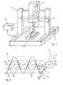
- a coordinate measuring machine 4is disclosed in Fig 1 according to a preferred embodiment of the invention.
- Such a machine 4is also known as CMM.
- the CMM 4comprises a scanning probe 2 attached to a support 3.
- the support 3can be moved in any linear direction (X, Y, Z), whereas the scanning probe 2 has two degrees of freedom in rotation with respect to the support 3.
- the axes for the rotation of the probeare vertical, respectively horizontal, but other combinations of axes could be considered (e.g. two independent orthogonal horizontal axes, or any number of rotational axes, or any combination of rotational and linear degrees of freedom).
- the CMMcould be equipped with several kind of measuring probes, including, for example, but not exclusively:
- the following descriptionwill be made with special reference to the first case of a touch-type probe 2, which is brought by the CMM 4 in contact relationship to the points of the surface 1 whose coordinate are to be measured, along a scanning path.
- a touch-type probe 2which is brought by the CMM 4 in contact relationship to the points of the surface 1 whose coordinate are to be measured, along a scanning path.
- the method of the inventionwould equally be applicable, by aligning the probe with those points of the surface whose coordinates are to be measured.
- the inventionincludes the steps of bringing the measuring probe, with the CMM, in a measuring relationship with points of the surface whose coordinates are to be measured, along a scanning path that is followed at constant speed.
- Support 3is movable in any linear direction (X, Y, Z) thanks to a first set of drive means represented schematically, in figure 1 , by electric motors 6, 7,8, by way of example.
- the positions of support 3 relative to axes X, Y, Zare measured by means of suitable encoders (not represented).
- actuation of motors 6, 7, 8 and the measures provided by the encodersare controlled and processed by a digital controller 33 of the CMM (visible in figure 1 ).
- the controlleris also responsible for reading the positioning of the encoders, and the output of the measuring probe, and to translate this data in coordinate of points of the surface 1.
- the trajectory 36 followed by the support 3, shown further on Fig. 4is preferably rectilinear, or at least is characterized by low acceleration levels in order to minimize the inertia effects.
- the probe 2is made of light material. While the support 3 is positioned to determine roughly an area to scan and moved along a preferably straight trajectory 36, the probe 2 is meant to make the scanning more efficient in providing more reference points and coordinate measures over the surface 1. In order to do so, the probe 2 can be moved transversally to the instantaneous direction of the rectilinear trajectory 36 with rotating movements relatively to the support 3. These rotary movements can be oscillatory movements, for example.
- a second set of drive means 14, 17,whose goal can be on one hand to determine angular speeds ⁇ 1 , ⁇ 2 according to a corresponding axis, but can also on the other hand be to apply a torque T 1 , T 2 allowing to keep the contact with the surface 1 while doing it.
- the tip of the probe 25, preferably spherical,can thus be maintained in contact with the scanned surface 1, while the scanning is performed at a constant speed V s that is defined later in this document.
- the contact force F between the tip of the probe 25 and the surface to scan 1is defined as the opposite of the reaction applied by the surface on the probe tip 25. This contact force also illustrated on Fig. 1 is hence normal to the plane tangent to the point of contact with the surface 1.
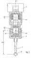
- Fig. 2is a section showing the mounting of the probe 2 on the support 3 and how the movements are actuated by the second set of drive means.
- this second set of drive meansis made up by two actuators 14, 17.
- the first actuator 14actuates a central shaft along the axis Z, and is preferably an electric motor.
- the probe head 24fits onto the bottom of the shaft, thereby fixing the probe 2 and transmitting the rotational movements to the probe 2.
- the derived angular speed of the rotational movements according to this axisis also referred to as ⁇ 1 .
- the probe head 24is designed so that the probe 2 can also freely rotate around another axis, whereby this second axis is orthogonal to the first axis (Z in this example) but its direction in the plane depends on the position of the central shaft.
- the second actuator 17actuates the rotational movements along this second axis, and is preferably also an electric motor.
- the derived angular speed of the rotational movements according to this axisis also referred to as ⁇ 2 .
- This point 20is the centre of both rotational movements and represents possibly the centre of a Galilean reference system when the support 3 is moved at a constant rectilinear speed.
- the length of the probe 23allows to determine the position of the contact point between the tip of the probe 25 and the intersection of the two axes 20, and thus in turn to derive the absolute coordinates of the contact point, since the coordinates of the point 20 along the trajectory 36 are known, as explained further in Fig. 3 .
- Fig. 3shows how the absolute coordinates of the probe tip 25 are obtained. They are determined by the angular positions ⁇ , ⁇ of the probe according to the axes of rotation. A simple transformation of the spherical coordinates (L, ⁇ , ⁇ ) into linear coordinates (X, Y, Z) yields the absolute coordinates.
- the orientation of the probe 2 in any direction ( ⁇ , ⁇ )provides a greater scanning flexibility since it allows to scan without losing the contact with a workpiece having a multiple angled surface 1 while the probe head 24 simply moves along a rectilinear trajectory 36. Furthermore, the inertia effects are minimized in taking a light weight stylus 2, as opposed to its heavy weight support 3.
- the absolute coordinates of the probe tip 25moves along the scanning path 37 that is made up by all contact points between the probe tip 25 and the surface 1.
- the absolute coordinates 44are stored in memory means.
- Fig 4shows a potential scanning path on a plane surface (x, y), and explains the composition of the speed vector on the probe tip 25.
- the surface to scan 1is represented by the dashed surface; it is here comprised within the plane (x,y) but could span the three dimensions of space (x,y,z).
- the trajectory 36 of the support 3is the rectilinear dotted line, which can point in any direction. The intrinsic movements of the probe combined with the movement of the support 3 along the trajectory 36 determine the scanning path 37 that is followed by the tip of the probe 25 and, at the same time, by the measured point 90.
- the measured point 90corresponds to the contact point between the tip of the probe 25 and the surface under measurement 1 in the case of a contact probe, but this is not necessarily the case if the invention is applied to a contactless measuring system, for example an optical probe.
- Fig. 2only shows the projection of this path in two dimensions, this path is not confined to a plane and can also span the three dimensions of space, according to curvature and shape of the object under measurement.
- the sum of the two composing speed vectorsnamely the speed vector v of the support on one hand, and the relative speed vector v r of the relative movement of the probe tip 25 with respect to the support on the other hand, must provide, by vector composition, a constant value or, or at least a value constant within a given approximation range, so that the accelerations are small and the friction forces do not wear away the tip of the probe 25 too quickly, while the inertia forces also remain negligible.
- the centre of the coordinate reference system for the relative movements of the probeis chosen as the point 20 of Fig 2 that is also shown on the top view of Fig 4 . Other choices of coordinates are however possible.
- Equation (4)is a separate-variables ordinary differential equation for x h (t) that can be easily integrated numerically, for any given set of parameters R , K, ⁇ (t) , provided that the inequality K ⁇ R ⁇ cos ⁇ ⁇ ⁇ ⁇ is satisfied, otherwise equation (4) has no real solutions. This corresponds to the fact that the value K must be sufficiently large to accommodate the speed imposed by the angular swing of the probe.
- the controller of the CMMcan therefore calculate, in real time or prior to the scanning, a path for the probe head 3, along which the translation speed is not strictly constant, but given by equation (4) above.
- the measured tip 25 of the probe 2will scan a series of points on the surface along a curvilinear path 37, resulting from the composition of the motion of the head 3 and of the probe 2, along which the measure point 90, corresponding to the point of contact in the case of a contact probe, moves with constant velocity
- K.
- the CMMcan be programmed in such a way as to maintain the speed
- equation (4)could yield an expression for x h (t) that exceeds the dynamic limits of the CMM. It may be possible, for example, that the constancy of velocity can not be guaranteed in proximity of the inversion points in the oscillation of the probe 2.
- the CMMcan be programmed to deal with such limitations. For example the speed may be kept constant in an area 41, or in selected segments 40 of the scanning path, in which the dynamic limitations of the CMM are not exceeded, and allowed to vary outside this area or these segments.
- the second motor 17is set to a constant torque T2.
- T1 of the first motor 14the torque required to maintain the torque T1 of the first motor 14 constant and the angular speed ⁇ 2 19 of the second motor 17 constant. This possibility is suited for surfaces with a different orientation relative to the rotation axis of the probe.
- the example aboveshows how the CMM can be programmed in order to follow a scanning path with the tip 25 of the probe (or, alternatively, measure a point 90 with a non-contact probe) while keeping a constant absolute scanning speed
- K . It is clear that the invention can be extended to scanning along a path with a variable scanning speed following a predetermined speed profile
- v a (t) .
- the method of the inventioncan be extended to a complex path on a general surface in three dimensions.
- the parameters of the CMM axesthat is the position of X, Y, Z, ⁇ , ⁇ axes is precalculated, or calculated in real time, using inverse-kinematics transformations, in order to follow a scanning path 37 on a generic three-dimensional object, which is followed at constant speed
- K or, according to a variant, following a predetermined speed profile
- v a (t).
- the CMM statusis determined by the value of the positions of all its degrees of freedom.
- the complete configurationis thus given by the position of all the axes of the machine, including the linear axes X, Y, Z and the rotation axes ⁇ , ⁇ .
- Each combination of these parameterscorresponds to one defined position of the probe 2, and to one measured point 90.
- the parameters X, Y, Z, ⁇ , ⁇determine, additionally, also the orientation of the probe 2. This correspondence between machine parameters and coordinates of the measured point is usually indicated as forward kinematics transformation
- the forward kinematicsis not an injective correspondence, that is, one same position of the measure point can be obtained by several combinations of machine parameters.
- the FK transformationis not strictly invertible in a mathematical sense. It is however possible to calculate, for a given position of the measure point 90, a combination, among the several possible, of the parameters X, Y, Z, ( ⁇ , ⁇ providing such measure point. This is indicated as an inverse kinematics operation or, in short, IK.
- the control on the orientation of the probeis advantageous, because the measurement errors are dependent on the probe angle, both in contact probe and in non-contact probes. If an optical probe is used, for example, it is advantageous to have the optical beam orthogonal to the surface under measure.
- the CMM controllerhas a representation of a scanning path 37 which is to be followed by the probe 2. This could be an external input, for example a path provided by the operator or by a higher controller, or it could be generating internally by the controller, according to the circumstances.
- the scan path 37is a full three-dimensional curve, corresponding to the profile of the piece to be measured.
- the scan path 37is subdivided into segments 61.
- all of the segments 61have the same length ⁇ l, because this simplifies the implementation of the algorithm of the invention; this feature is not however essential.
- the subdivisions 61are sufficiently small to approximate the path 37 with a succession of straight segments.
- Each segment 61corresponds to a starting point and a target point to reach.
- the CMMbrings the probe 2 in the position of the starting point P 0 of the first segment, which corresponds to a certain starting set of axes parameters (X 0 , Y 0 , Z 0 , ⁇ 0 , ⁇ 0 ).
- the controllerobtains, by an IK operation, a set of parameters (X 1 , Y 1 , Z 1 , ⁇ 1 , ⁇ 1 ) corresponding to the end point P 1 of the same segment.
- the controllergenerates then instructions for the actuators of the CMM to modify the axes parameters from (X 0 , Y 0 , Z 0 , ⁇ 0 , ⁇ 0 ) to (X 1 , Y 1 , Z 1 , ⁇ 1 , ⁇ 1 ) in a determined time interval ⁇ t. Consequently the probe 2 moves from P 0 to P 1 in the time ⁇ t . The method then repeats to points P 2 , P 3 and so on.
- the probe 2scans the path 37 with a constant velocity
- ⁇ l/ ⁇ t .
- the methodallows the probe to follow a complex three-dimensional path, respecting the shape of the object under measurement, at constant speed. the skilled person could also extend the method to the case of non-uniform segments, by adapting the time intervals accordingly, or to obtain a generic speed profile
- v a (t).
- the IK transformationimposes some additional desirable constraints, for example the inclination of the probe with respect to the workpiece's surface can be kept constant along the path 37.
- the minimization algorithmcan be adapted to prefer movement of the rotational axes over those of the linear axes, in order to minimize vibrations and errors.
- the controller of the CMMWhile the probe 2 scans the path 37, the controller of the CMM also samples the coordinates of the measure points 60. This can be done for example in correspondence of the points P 0 , P 1 , ... or at other positions along the path 37. If the sample is done at constant rate in time, the resulting measured points will also be uniformly distributed along the path 37.
- the methodis carried out in real-time during the scan.
- the CMM controllercalculates the IK transformations and generates the instructions for the actuator during the actual movement. This allows adapting the path 37 in order to follow deviations from a nominal profile, as derived from the coordinates of the sampled points 60. According to other variants, however, the movements could be fully or partly pre-calculated.
- the inverse kinematics approach for adjusting the speedis also suited to make instantaneous corrections of the speed when the measured coordinates 44 do not match the theoretical coordinates 60 on the scanning path 37. Indeed, since the speed is derived from a difference in coordinates - origin and the target coordinates - and since the instantaneous coordinates are always known while scanning, the computation of the speed its adjustment to any desired value can be done easily and accurately on the fly, as long as the measured coordinates are themselves accurate.
- the deflection of the probemust be kept within very narrow limits in order to guarantee a reliable measure.
- the useful deflection range of the probe 2is of about 1 mm, or less.
- the scanning path 37is constantly adapted, for any individual workpiece and dynamically along the scan, to maintain the deflection as constant as possible. If the transitions between the individual steps P 0 , P 1 , ... are computed in real time, the system will still be able to follow the path at constant velocity
- the IK transformationmay, in some cases, result in impossible instructions, for example movements that go beyond the physical speed or acceleration limits of the CMM.
- the chosen path 37can not be followed entirely at constant speed.
- the CMMcan be programmed to cope with such a situation, for example by generating an error to raise the attention of an operator, calling a condition-handling procedure, or release the constraint of constant speed, until the algorithm is able to converge again.
Landscapes
- Physics & Mathematics (AREA)
- General Physics & Mathematics (AREA)
- Length Measuring Devices With Unspecified Measuring Means (AREA)
- A Measuring Device Byusing Mechanical Method (AREA)
Description
- The present invention concerns a method for scanning the surface of a workpiece and a related apparatus.
- Numerous methods for scanning are known, in which a mechanical probe is fixed on a machine spindle which traverses the surface of a workpiece in straight lines over each possible direction (x,y,z). After each line is completed the machine spindle moves the probe to a new position displaced from the completed line and repeats the movement along a parallel line.
- One major drawback of these methods known from the art is that they are relatively slow for scanning complex forms, since the whole machine needs to be moved backwards and forwards while covering the whole scanning area of the surface. Furthermore, the accelerations and decelerations of the machine can introduce inaccuracies in the measurement process because of the strong inertia forces due to the large mass of the pieces in charge of positioning the surface detecting device. As a result, elastic deformations induced by inertia forces can affect negatively the measures.
- In order to minimize the inertia effects and thus guarantee better precision results, constant speed scanning apparatus have been introduced, as in
EP1489377 . These scanning apparatus are yet not suited for non rectilinear movements. - Other scanning apparatus involving rotating movements of a probe are also known. Such scanning methods are, in contrast, very well suited for surfaces with spherical or cylindrical forms, but not for plane surfaces.
US5895442 describes an example of such a probe allowing for constant speed scanning along cylindrical or spherical surfaces thanks to stored corrective values. EP0402440 and, equivalently,WO9007097 WO2007017235 discloses an articulated robot arm used to measure coordinates of points with a scanning probe.- The airn of the present invention is to overcome the limitations of the solutions known from the prior of the art.
- According to the invention, these aims are achieved by means of a method as defined in
Claim 1 and a computer program product as defined in Claim 9. - This invention fulfils the need in the measuring field of a scanning apparatus that can scan all types of surfaces efficiently, e.g. through oscillatory movements, while maintaining a very accurate precision during the whole measurement process, possibly over the whole scanning path. The feature of a constant scanning speed also improves the lifetime of the probes by reducing the overheating due to greater friction forces in acceleration phases.
- Another benefit of the disclosed scanning apparatus is a simple sampling process in order to provide an even distribution of discrete points whose coordinates need to be measured on a surface along the scanning path. Indeed the points will be equally spread along the scanning path by simply setting regular time intervals for the sampling.
- The invention will be better understood with the aid of the description of an embodiment given by way of example and illustrated by the figures, in which:
Fig. 1 shows a coordinate measuring machine and the scanning apparatus for the application of the present inventionFig 2 is a section showing the mounting of the probe.Fig 3 shows a 3D view of the scanning probe and its angular positions.Fig 4 shows a top view of the scanning path followed by the probe and illustrates the speed vector composition.Fig 5 explains how the speed adjustment process is carried out according to another aspect of the present invention.- A
coordinate measuring machine 4 is disclosed inFig 1 according to a preferred embodiment of the invention. Such amachine 4 is also known as CMM. TheCMM 4 comprises ascanning probe 2 attached to asupport 3. Thesupport 3 can be moved in any linear direction (X, Y, Z), whereas thescanning probe 2 has two degrees of freedom in rotation with respect to thesupport 3. In this example, the axes for the rotation of the probe are vertical, respectively horizontal, but other combinations of axes could be considered (e.g. two independent orthogonal horizontal axes, or any number of rotational axes, or any combination of rotational and linear degrees of freedom). - According to the circumstances, the CMM could be equipped with several kind of measuring probes, including, for example, but not exclusively:
- a contact probe, as represented in
fig. 2 , wherein a touch sphere is urged against the surface under measurement, and the coordinates of the contact point are computed by taking into account the deflection of the probe, given by a strain gauge or other appropriate transducer; - a laser probe (not represented) in which the probe shines one or more laser beams on the surface, and gives the distance along the light paths;
- an optical probe, based on a micro imaging device or machine vision system.
- The following description will be made with special reference to the first case of a touch-
type probe 2, which is brought by theCMM 4 in contact relationship to the points of thesurface 1 whose coordinate are to be measured, along a scanning path. This is not, however an essential feature. In the case of a non-contact probe, the method of the invention would equally be applicable, by aligning the probe with those points of the surface whose coordinates are to be measured. Generally the invention includes the steps of bringing the measuring probe, with the CMM, in a measuring relationship with points of the surface whose coordinates are to be measured, along a scanning path that is followed at constant speed. - In the following, the directions "vertical" and "horizontal" are used with reference to the conventional orientation of a CMM, as illustrated on
figure 1 . It must be understood, however, that such orientation are used here for sake of clarity, and do not represent limitations of the invention, which can be implemented in other kinds of measuring apparatus, arbitrarily oriented in space. Support 3 is movable in any linear direction (X, Y, Z) thanks to a first set of drive means represented schematically, infigure 1 , byelectric motors support 3 relative to axes X, Y, Z are measured by means of suitable encoders (not represented). Preferably, actuation ofmotors digital controller 33 of the CMM (visible infigure 1 ). The controller is also responsible for reading the positioning of the encoders, and the output of the measuring probe, and to translate this data in coordinate of points of thesurface 1.- Since most of the components of the
support 3 are quite heavy, thetrajectory 36 followed by thesupport 3, shown further onFig. 4 , is preferably rectilinear, or at least is characterized by low acceleration levels in order to minimize the inertia effects. - In contrast to support 3 the
probe 2 is made of light material. While thesupport 3 is positioned to determine roughly an area to scan and moved along a preferablystraight trajectory 36, theprobe 2 is meant to make the scanning more efficient in providing more reference points and coordinate measures over thesurface 1. In order to do so, theprobe 2 can be moved transversally to the instantaneous direction of therectilinear trajectory 36 with rotating movements relatively to thesupport 3. These rotary movements can be oscillatory movements, for example. They are actuated by a second set of drive means 14, 17, whose goal can be on one hand to determine angular speeds ω1, ω2 according to a corresponding axis, but can also on the other hand be to apply a torque T1, T2 allowing to keep the contact with thesurface 1 while doing it. The tip of theprobe 25, preferably spherical, can thus be maintained in contact with the scannedsurface 1, while the scanning is performed at a constant speed Vs that is defined later in this document. The contact force F between the tip of theprobe 25 and the surface toscan 1 is defined as the opposite of the reaction applied by the surface on theprobe tip 25. This contact force also illustrated onFig. 1 is hence normal to the plane tangent to the point of contact with thesurface 1. Fig. 2 is a section showing the mounting of theprobe 2 on thesupport 3 and how the movements are actuated by the second set of drive means. Preferably this second set of drive means is made up by twoactuators first actuator 14 actuates a central shaft along the axis Z, and is preferably an electric motor. Theprobe head 24 fits onto the bottom of the shaft, thereby fixing theprobe 2 and transmitting the rotational movements to theprobe 2. The derived angular speed of the rotational movements according to this axis is also referred to as ω1.- The
probe head 24 is designed so that theprobe 2 can also freely rotate around another axis, whereby this second axis is orthogonal to the first axis (Z in this example) but its direction in the plane depends on the position of the central shaft. Thesecond actuator 17 actuates the rotational movements along this second axis, and is preferably also an electric motor. The derived angular speed of the rotational movements according to this axis is also referred to as ω2. - In this example we assume, for the sake of simplicity, that the two axes of
motors space 20, even if it is not necessarily always the case. The skilled person would be able to see that our derivations and the methods of the invention apply equally to the general case. Thispoint 20 is the centre of both rotational movements and represents possibly the centre of a Galilean reference system when thesupport 3 is moved at a constant rectilinear speed. The length of theprobe 23 allows to determine the position of the contact point between the tip of theprobe 25 and the intersection of the twoaxes 20, and thus in turn to derive the absolute coordinates of the contact point, since the coordinates of thepoint 20 along thetrajectory 36 are known, as explained further inFig. 3 . Fig. 3 shows how the absolute coordinates of theprobe tip 25 are obtained. They are determined by the angular positions α, ϑ of the probe according to the axes of rotation. A simple transformation of the spherical coordinates (L, α, ϑ) into linear coordinates (X, Y, Z) yields the absolute coordinates. The orientation of theprobe 2 in any direction (α,ϑ) provides a greater scanning flexibility since it allows to scan without losing the contact with a workpiece having a multipleangled surface 1 while theprobe head 24 simply moves along arectilinear trajectory 36. Furthermore, the inertia effects are minimized in taking alight weight stylus 2, as opposed to itsheavy weight support 3. The absolute coordinates of theprobe tip 25 moves along thescanning path 37 that is made up by all contact points between theprobe tip 25 and thesurface 1. In a preferred embodiment of the invention, the absolute coordinates 44 are stored in memory means.Fig 4 shows a potential scanning path on a plane surface (x, y), and explains the composition of the speed vector on theprobe tip 25. The surface to scan 1 is represented by the dashed surface; it is here comprised within the plane (x,y) but could span the three dimensions of space (x,y,z). Thetrajectory 36 of thesupport 3 is the rectilinear dotted line, which can point in any direction. The intrinsic movements of the probe combined with the movement of thesupport 3 along thetrajectory 36 determine thescanning path 37 that is followed by the tip of theprobe 25 and, at the same time, by the measuredpoint 90. It is important to note that the measuredpoint 90 corresponds to the contact point between the tip of theprobe 25 and the surface undermeasurement 1 in the case of a contact probe, but this is not necessarily the case if the invention is applied to a contactless measuring system, for example an optical probe. AlthoughFig. 2 only shows the projection of this path in two dimensions, this path is not confined to a plane and can also span the three dimensions of space, according to curvature and shape of the object under measurement.- In order to keep the magnitude of the
speed vector 26 at the level of theprobe tip 25 constant, the sum of the two composing speed vectors, namely the speed vector v of the support on one hand, and the relative speed vector vr of the relative movement of theprobe tip 25 with respect to the support on the other hand, must provide, by vector composition, a constant value or, or at least a value constant within a given approximation range, so that the accelerations are small and the friction forces do not wear away the tip of theprobe 25 too quickly, while the inertia forces also remain negligible. The centre of the coordinate reference system for the relative movements of the probe is chosen as thepoint 20 ofFig 2 that is also shown on the top view ofFig 4 . Other choices of coordinates are however possible. - In the case of a plane surface as shown in
Fig 4 , the relative speed of the point under measure, with respect to thecentre 20 of thesupport 3 is represented by the vectorvr. Assuming that the angle α is variable according to a predefined motion law α = α(t), while the angle ϑ is fixed, in this example. The horizontal distance betweencentre 20 and thecontact point 90 is given by the constant quantityR=L·sin(ϑ). Hence the coordinatesxr, yr of thecontact point 90 relative to thecentre 20 will be given by:
and the corresponding horizontal componentsvrx and vry of the relative speed vectorvr by:
- We have taken, for simplicity, a
path 36 for thehead 3 parallel to the X axis the translation speed of thehead 3. In this case, which is straightforward to generalize, the motion of thehead 3 is fully described by its x coordinateXh(t) and by the relative velocityv(t)=dxh/dt. The absolute speed Va of themeasure point 90 with respect to the object under measurement has then components:
- Requiring constant absolute speed of the contact point |va | =K introduces a relationship between xh(t) and α(t)

where the right-handed part is fully known. Equation (4) is a separate-variables ordinary differential equation forxh(t) that can be easily integrated numerically, for any given set of parametersR,K, α(t), provided that the inequality
is satisfied, otherwise equation (4) has no real solutions. This corresponds to the fact that the valueK must be sufficiently large to accommodate the speed imposed by the angular swing of the probe. - It can be observed that equation (4) could provide, in some cases, solutions in whichv(t)=dxh/dt changes sign, which would correspond to a back-and-forth motion of the machine head 3.ln many cases, however, it would be advantageous to chose the value ofK, in relation to the amplitude and speed of oscillation in α, in order to obtain a motion of the head always in the same sense, to reduce oscillations and errors.
- The controller of the CMM can therefore calculate, in real time or prior to the scanning, a path for the
probe head 3, along which the translation speed is not strictly constant, but given by equation (4) above. In this way the measuredtip 25 of theprobe 2 will scan a series of points on the surface along acurvilinear path 37, resulting from the composition of the motion of thehead 3 and of theprobe 2, along which themeasure point 90, corresponding to the point of contact in the case of a contact probe, moves with constant velocity |va | =K. - It is of course not possible to impose a rigorous constant speed with infinite precision. The real speed of the
point 90 will, in real cases, be affected by some error, due to the limitation of the machine and of the computing algorithm. In this case, the CMM can be programmed in such a way as to maintain the speed |va | constant within some defined tolerance. - In some cases, particularly in presence of rapid swings of the
probe 2, equation (4) could yield an expression forxh(t) that exceeds the dynamic limits of the CMM. It may be possible, for example, that the constancy of velocity can not be guaranteed in proximity of the inversion points in the oscillation of theprobe 2. According to another aspect of the invention the CMM can be programmed to deal with such limitations. For example the speed may be kept constant in anarea 41, or in selectedsegments 40 of the scanning path, in which the dynamic limitations of the CMM are not exceeded, and allowed to vary outside this area or these segments. - According to this preferred embodiment of the invention, it is possible to easily sample coordinates 44 regularly along the segments of the
scanning path 40 on the scanning speed |va | is constant. The time intervals simply need to be chosen equal so that the coordinates 44 sampled are equally spread along thescanning path 37. With this scanning method, it is hence easy to obtain an efficient distribution of the points to be measured in choosing adequately the values for the boundary and the sampling time interval Δt. The coordinates measured 44 can be stored in the memory of the controller on the fly. - In a preferred embodiment of the invention, not only the speed is maintained constant but also the deflecting force F applied to the tip of the
probe 2 so that the coordinates measured along thescanning path 37 are as accurate as possible. To this end, while theangular speed 16 ω1 is maintained constant on segments of thescanning path 37 by thefirst motor 14, thesecond motor 17 is set to a constant torque T2. Although the following variant embodiment is not described, it would also be possible to maintain the torque T1 of thefirst motor 14 constant and theangular speed ω 2 19 of thesecond motor 17 constant. This possibility is suited for surfaces with a different orientation relative to the rotation axis of the probe. - Although this feature is not illustrated by any of the figures, it could be possible to put an accelerometer into the
probe 2 so that the speed can be measured and compared the value that the invention strives to maintain at a constant level. This feedback feature could nevertheless be provided regardless from the correction features disclosed in this document. - The example above shows how the CMM can be programmed in order to follow a scanning path with the
tip 25 of the probe (or, alternatively, measure apoint 90 with a non-contact probe) while keeping a constant absolute scanning speed |va |=K. It is clear that the invention can be extended to scanning along a path with a variable scanning speed following a predetermined speed profile |va |=va(t). - Although the previous example dealt with a quite simple case, the method of the invention can be extended to a complex path on a general surface in three dimensions.
- According to a preferred three-dimensional embodiment of the invention, the parameters of the CMM axes, that is the position of X, Y, Z, α, θ axes is precalculated, or calculated in real time, using inverse-kinematics transformations, in order to follow a
scanning path 37 on a generic three-dimensional object, which is followed at constant speed |va | =K or, according to a variant, following a predetermined speed profile |va | =va(t). - We assume that the CMM status is determined by the value of the positions of all its degrees of freedom. In the case of the machine represented in
figures 1 and2 , the complete configuration is thus given by the position of all the axes of the machine, including the linear axes X, Y, Z and the rotation axes α, ϑ. Each combination of these parameters corresponds to one defined position of theprobe 2, and to one measuredpoint 90. The parameters X, Y, Z, α, ϑ determine, additionally, also the orientation of theprobe 2. This correspondence between machine parameters and coordinates of the measured point is usually indicated as forward kinematics transformation - In general, particularly when the machine considered includes rotational degrees of freedom, the forward kinematics is not an injective correspondence, that is, one same position of the measure point can be obtained by several combinations of machine parameters. In this case, the FK transformation is not strictly invertible in a mathematical sense. It is however possible to calculate, for a given position of the
measure point 90, a combination, among the several possible, of the parameters X, Y, Z, (α, ϑ providing such measure point. This is indicated as an inverse kinematics operation or, in short, IK. - Several methods are known to perform reverse kinematics transformation, according to the properties of the machine. While direct inversion methods are known, inverse kinematics can often be regarded and implemented as a minimization problem, in the sense that an IK transformation is equivalent to finding a combination of machine parameters minimizing a distance between the probe tip and a desired target position. This is often advantageous when the displacements are small and a close solution is available as a starting point, and when a movement can be decomposed in a series of small consecutive displacement, as it will be the case further on.
- The inherent ambiguity of inverse kinematics transformation can be useful, in that it allows imposing additional constraints to the solution. In the case of the CMM of the invention, for example, it would be possible to use an inverse kinematics calculation that not only brings the measuring probe to a selected measure point, but also maintains a constant inclination of the
probe 2 with respect to the surface of the workpiece. In a minimization implementation, this can be obtained by adding a penalty factor to the minimized function, to take into account the orientation of the probe. - The control on the orientation of the probe is advantageous, because the measurement errors are dependent on the probe angle, both in contact probe and in non-contact probes. If an optical probe is used, for example, it is advantageous to have the optical beam orthogonal to the surface under measure.
- According to a variant of the present invention, the CMM controller has a representation of a
scanning path 37 which is to be followed by theprobe 2. This could be an external input, for example a path provided by the operator or by a higher controller, or it could be generating internally by the controller, according to the circumstances. Thescan path 37 is a full three-dimensional curve, corresponding to the profile of the piece to be measured. - As shown in
figure 5 , thescan path 37 is subdivided intosegments 61. In this example all of thesegments 61 have the same length Δℓ, because this simplifies the implementation of the algorithm of the invention; this feature is not however essential. Preferably thesubdivisions 61 are sufficiently small to approximate thepath 37 with a succession of straight segments. - Each
segment 61 corresponds to a starting point and a target point to reach. The CMM brings theprobe 2 in the position of the starting point P0 of the first segment, which corresponds to a certain starting set of axes parameters (X0, Y0, Z0, α0, ϑ0). The controller obtains, by an IK operation, a set of parameters (X1, Y1, Z1, α1, ϑ1) corresponding to the end point P1 of the same segment. The controller generates then instructions for the actuators of the CMM to modify the axes parameters from (X0, Y0, Z0, α0, ϑ0) to (X1, Y1, Z1, α1, ϑ1) in a determined time interval Δt. Consequently theprobe 2 moves from P0 to P1 in the time Δt. The method then repeats to points P2, P3 and so on. - Thanks to the method of the invention as exemplified above, the
probe 2 scans thepath 37 with a constant velocity |va | = Δℓ/ Δt. The method allows the probe to follow a complex three-dimensional path, respecting the shape of the object under measurement, at constant speed. the skilled person could also extend the method to the case of non-uniform segments, by adapting the time intervals accordingly, or to obtain a generic speed profile |va | =va(t). - Preferably, the IK transformation imposes some additional desirable constraints, for example the inclination of the probe with respect to the workpiece's surface can be kept constant along the
path 37. Also, the minimization algorithm can be adapted to prefer movement of the rotational axes over those of the linear axes, in order to minimize vibrations and errors. - While the
probe 2 scans thepath 37, the controller of the CMM also samples the coordinates of the measure points 60. This can be done for example in correspondence of the points P0, P1, ... or at other positions along thepath 37. If the sample is done at constant rate in time, the resulting measured points will also be uniformly distributed along thepath 37. - According to a preferred variant of the invention, the method is carried out in real-time during the scan. The CMM controller calculates the IK transformations and generates the instructions for the actuator during the actual movement. This allows adapting the
path 37 in order to follow deviations from a nominal profile, as derived from the coordinates of the sampled points 60. According to other variants, however, the movements could be fully or partly pre-calculated. - The inverse kinematics approach for adjusting the speed is also suited to make instantaneous corrections of the speed when the measured coordinates 44 do not match the
theoretical coordinates 60 on thescanning path 37. Indeed, since the speed is derived from a difference in coordinates - origin and the target coordinates - and since the instantaneous coordinates are always known while scanning, the computation of the speed its adjustment to any desired value can be done easily and accurately on the fly, as long as the measured coordinates are themselves accurate. - If the CMM is equipped with a
contact scanning probe 2, the deflection of the probe must be kept within very narrow limits in order to guarantee a reliable measure. In a typical case, the useful deflection range of theprobe 2 is of about 1 mm, or less. Such precise knowledge a priori is not always possible. In many situations (for example in a quality control step of a production line) the CMM task is to scan precisely objects which may be affected by a large amount of inaccuracy. - In order to make sure that the coordinates are always provided with enough accuracy, it possible to modify in real time the
scanning path 37 according to a compensation vector derived from the coordinates ofpoints 60 already measured, and from the output of the deflection sensor in the probe. In this way thescan path 37 is constantly adapted, for any individual workpiece and dynamically along the scan, to maintain the deflection as constant as possible. If the transitions between the individual steps P0, P1, ... are computed in real time, the system will still be able to follow the path at constant velocity |va |. Since constancy of deflection also means constancy of the contact force, the method also provides, when applied to a contact scanning probe, a constant contact force along a three-dimensional scan path 37 which is followed at constant speed or according to a chosen speed profile. - As seen previously, the IK transformation may, in some cases, result in impossible instructions, for example movements that go beyond the physical speed or acceleration limits of the CMM. In this case, the chosen
path 37 can not be followed entirely at constant speed. The CMM can be programmed to cope with such a situation, for example by generating an error to raise the attention of an operator, calling a condition-handling procedure, or release the constraint of constant speed, until the algorithm is able to converge again.


Claims (9)
- A method for scanning a surface of a workpiece (1) using a scanning probe (2) mounted on a support (3), said scanning probe (2) having a probe tip that can be maintained in contact with the surface of the workpiece following a scanning path on a coordinate measuring machine (4), said CMM containing a first set of drive means (6, 7, 8) to move said support (3) according to three linear axis (x,y,z), said support (3) containing a second set of drive means (14, 17) for actuating the movement of said scanning probe (2) relative to said support (3), said method further involving control means (33) coupled to both said sets of drive means (6, 7, 8,14, 17), said method comprising the steps of:(i) determine a value for a scanning speed (|va |) of the point of contact of the probe tip with the surface of the workpiece;(ii) operate said sets of drive means (6, 7, 8,14, 17) to position the probe tip (25) in contact with said surface (1);(iii) operate said first set of drive means (6, 7, 8) to move the support (3) along a determined trajectory (36);(iv) operate said second set of drive means (14, 17) to produce, simultaneously with the relative movement of the support (3) with respect to the surface, movements of said scanning probe (2) relative to the support (3);characterised in that the said control means (33) adjust according to at least one inverse kinematics transformation the actuation of both said sets of drive means (6, 7, 8, 14, 17) along said scanning path (37) in order to maintain said scanning speed of said probe tip (25) equal to said determined Value (|va |) on at least segments (40) of said scanning path (37), and to maintain constant the inclination of the probe (2) with respect to the surface of the piece to be measured (1).
- The method according to claim 1, said at least one inverse kinematics transformation using coordinates (60) equally spaced over said scanning path (37).
- The method of claim 1 or 2, whereby the movements of said scanning probe relative to the support are oscillatory movements.
- The method of any of the previous claims, whereby the movements of said scanning probe relative to the support are oscillatory movements,
- The method of either of the previous claims, whereby the movement adjustment carried out by said control means (33) is made according to the angular position (22,23) of said probe (2).
- The method of any of the previous claims, wherein said probe (2) is a contact probe, and wherein the second set of drive means is operated in such a way as to maintain constant the contact force (F) between the probe and the piece to be measured (1).
- The method of any of claims 1-5, wherein said probe is a contactless optical probe.
- The method according to any of the previous claims, whereby coordinates are sampled discretely at regular time intervals (Δt) along said scanning path (37).
- A computer program product comprising program code for carrying out the method according to any of the preceding claims.
Priority Applications (6)
| Application Number | Priority Date | Filing Date | Title |
|---|---|---|---|
| EP07106415AEP1983297B1 (en) | 2007-04-18 | 2007-04-18 | Scanning probe with constant scanning speed |
| DE602007005778TDE602007005778D1 (en) | 2007-04-18 | 2007-04-18 | Probe with constant grid speed |
| US12/053,164US7647706B2 (en) | 2007-04-18 | 2008-03-21 | Scanning probe with constant scanning speed |
| CN2008100963812ACN101290212B (en) | 2007-04-18 | 2008-04-17 | Method for scanning workpiece surface |
| JP2008107560AJP5602344B2 (en) | 2007-04-18 | 2008-04-17 | Method of scanning the surface of an object to be measured using a scanning probe with a constant scanning speed |
| HK09100255.1AHK1123092B (en) | 2007-04-18 | 2009-01-09 | Method for scanning a surface of a workpiece |
Applications Claiming Priority (1)
| Application Number | Priority Date | Filing Date | Title |
|---|---|---|---|
| EP07106415AEP1983297B1 (en) | 2007-04-18 | 2007-04-18 | Scanning probe with constant scanning speed |
Publications (2)
| Publication Number | Publication Date |
|---|---|
| EP1983297A1 EP1983297A1 (en) | 2008-10-22 |
| EP1983297B1true EP1983297B1 (en) | 2010-04-07 |
Family
ID=38529470
Family Applications (1)
| Application Number | Title | Priority Date | Filing Date |
|---|---|---|---|
| EP07106415AActiveEP1983297B1 (en) | 2007-04-18 | 2007-04-18 | Scanning probe with constant scanning speed |
Country Status (5)
| Country | Link |
|---|---|
| US (1) | US7647706B2 (en) |
| EP (1) | EP1983297B1 (en) |
| JP (1) | JP5602344B2 (en) |
| CN (1) | CN101290212B (en) |
| DE (1) | DE602007005778D1 (en) |
Families Citing this family (65)
| Publication number | Priority date | Publication date | Assignee | Title |
|---|---|---|---|---|
| GB0605796D0 (en) | 2006-03-23 | 2006-05-03 | Renishaw Plc | Apparatus and method of measuring workpieces |
| GB0609022D0 (en)* | 2006-05-08 | 2006-06-14 | Renishaw Plc | Contact sensing probe |
| US7659509B2 (en)* | 2006-10-31 | 2010-02-09 | Agilent Technologies, Inc. | System for scanning probe microscope input device |
| GB0625260D0 (en)* | 2006-12-19 | 2007-01-24 | Renishaw Plc | A method for measuring a workpiece using a machine tool |
| JP2009028871A (en)* | 2007-07-30 | 2009-02-12 | Denso Wave Inc | Robot control device |
| US9551575B2 (en) | 2009-03-25 | 2017-01-24 | Faro Technologies, Inc. | Laser scanner having a multi-color light source and real-time color receiver |
| DE102009015920B4 (en) | 2009-03-25 | 2014-11-20 | Faro Technologies, Inc. | Device for optically scanning and measuring an environment |
| JP5371532B2 (en) | 2009-04-23 | 2013-12-18 | 株式会社ミツトヨ | CMM |
| US9113023B2 (en) | 2009-11-20 | 2015-08-18 | Faro Technologies, Inc. | Three-dimensional scanner with spectroscopic energy detector |
| US9529083B2 (en) | 2009-11-20 | 2016-12-27 | Faro Technologies, Inc. | Three-dimensional scanner with enhanced spectroscopic energy detector |
| DE102009057101A1 (en) | 2009-11-20 | 2011-05-26 | Faro Technologies, Inc., Lake Mary | Device for optically scanning and measuring an environment |
| US9210288B2 (en) | 2009-11-20 | 2015-12-08 | Faro Technologies, Inc. | Three-dimensional scanner with dichroic beam splitters to capture a variety of signals |
| US8630314B2 (en) | 2010-01-11 | 2014-01-14 | Faro Technologies, Inc. | Method and apparatus for synchronizing measurements taken by multiple metrology devices |
| WO2011090895A1 (en) | 2010-01-20 | 2011-07-28 | Faro Technologies, Inc. | Portable articulated arm coordinate measuring machine with multi-bus arm technology |
| US9628775B2 (en) | 2010-01-20 | 2017-04-18 | Faro Technologies, Inc. | Articulated arm coordinate measurement machine having a 2D camera and method of obtaining 3D representations |
| US8677643B2 (en) | 2010-01-20 | 2014-03-25 | Faro Technologies, Inc. | Coordinate measurement machines with removable accessories |
| US8942940B2 (en)* | 2010-01-20 | 2015-01-27 | Faro Technologies, Inc. | Portable articulated arm coordinate measuring machine and integrated electronic data processing system |
| US8898919B2 (en) | 2010-01-20 | 2014-12-02 | Faro Technologies, Inc. | Coordinate measurement machine with distance meter used to establish frame of reference |
| US8284407B2 (en) | 2010-01-20 | 2012-10-09 | Faro Technologies, Inc. | Coordinate measuring machine having an illuminated probe end and method of operation |
| US9607239B2 (en) | 2010-01-20 | 2017-03-28 | Faro Technologies, Inc. | Articulated arm coordinate measurement machine having a 2D camera and method of obtaining 3D representations |
| US8875409B2 (en) | 2010-01-20 | 2014-11-04 | Faro Technologies, Inc. | Coordinate measurement machines with removable accessories |
| US9163922B2 (en) | 2010-01-20 | 2015-10-20 | Faro Technologies, Inc. | Coordinate measurement machine with distance meter and camera to determine dimensions within camera images |
| US8832954B2 (en) | 2010-01-20 | 2014-09-16 | Faro Technologies, Inc. | Coordinate measurement machines with removable accessories |
| US8615893B2 (en) | 2010-01-20 | 2013-12-31 | Faro Technologies, Inc. | Portable articulated arm coordinate measuring machine having integrated software controls |
| US9879976B2 (en) | 2010-01-20 | 2018-01-30 | Faro Technologies, Inc. | Articulated arm coordinate measurement machine that uses a 2D camera to determine 3D coordinates of smoothly continuous edge features |
| EP2385339A1 (en)* | 2010-05-05 | 2011-11-09 | Leica Geosystems AG | Surface sensing device with optical monitoring system |
| DE102010020925B4 (en) | 2010-05-10 | 2014-02-27 | Faro Technologies, Inc. | Method for optically scanning and measuring an environment |
| US8712721B2 (en)* | 2010-07-08 | 2014-04-29 | Shayne Hamel | Adjustable high precision surveying device |
| GB2501390B (en) | 2010-09-08 | 2014-08-06 | Faro Tech Inc | A laser scanner or laser tracker having a projector |
| US9063534B2 (en)* | 2010-10-13 | 2015-06-23 | Mbda Uk Limited | Workpiece positioning method and apparatus |
| US9168654B2 (en) | 2010-11-16 | 2015-10-27 | Faro Technologies, Inc. | Coordinate measuring machines with dual layer arm |
| DE102010052503B4 (en) | 2010-11-26 | 2012-06-21 | Wenzel Scantec Gmbh | Method for controlling a coordinate measuring machine and coordinate measuring machine |
| US8701298B2 (en)* | 2011-06-01 | 2014-04-22 | Tesa Sa | Coordinate measuring machine |
| CN103782130B (en)* | 2011-07-08 | 2017-06-20 | 卡尔蔡司工业测量技术有限公司 | Error correction and/or avoidance when measuring the coordinates of a workpiece |
| CN102519370B (en)* | 2011-12-16 | 2014-07-16 | 哈尔滨工业大学 | Micropore measurer based on orthogonal two-dimensional micro-focus collimation and method |
| DE102012100609A1 (en) | 2012-01-25 | 2013-07-25 | Faro Technologies, Inc. | Device for optically scanning and measuring an environment |
| DE102012205599A1 (en)* | 2012-04-04 | 2013-10-10 | Carl Zeiss Industrielle Messtechnik Gmbh | Reduction of errors of a rotating device in the determination of coordinates of a workpiece or in the machining of a workpiece |
| JP6030339B2 (en)* | 2012-05-17 | 2016-11-24 | 株式会社ミツトヨ | Shape measuring device |
| US9157721B1 (en)* | 2012-06-08 | 2015-10-13 | Beeline Company | Measuring system |
| US8997362B2 (en) | 2012-07-17 | 2015-04-07 | Faro Technologies, Inc. | Portable articulated arm coordinate measuring machine with optical communications bus |
| US10067231B2 (en) | 2012-10-05 | 2018-09-04 | Faro Technologies, Inc. | Registration calculation of three-dimensional scanner data performed between scans based on measurements by two-dimensional scanner |
| DE102012109481A1 (en) | 2012-10-05 | 2014-04-10 | Faro Technologies, Inc. | Device for optically scanning and measuring an environment |
| US9513107B2 (en) | 2012-10-05 | 2016-12-06 | Faro Technologies, Inc. | Registration calculation between three-dimensional (3D) scans based on two-dimensional (2D) scan data from a 3D scanner |
| US10132622B2 (en)* | 2013-02-05 | 2018-11-20 | Renishaw Plc | Method and apparatus for measuring a part |
| JP6144157B2 (en)* | 2013-08-26 | 2017-06-07 | 株式会社ミツトヨ | Shape measuring device and V-groove centripetal measuring method |
| US9740190B2 (en)* | 2014-10-09 | 2017-08-22 | Mitutoyo Corporation | Method for programming a three-dimensional workpiece scan path for a metrology system |
| CA2939029A1 (en)* | 2015-08-21 | 2017-02-21 | Williams & White Machine Inc. | Feed finger positioning apparatus and methods |
| DE102015122844A1 (en) | 2015-12-27 | 2017-06-29 | Faro Technologies, Inc. | 3D measuring device with battery pack |
| JP6613162B2 (en)* | 2016-02-10 | 2019-11-27 | 株式会社ミツトヨ | Probe head and contact detection method for three-dimensional coordinate measuring machine |
| JP6774240B2 (en)* | 2016-07-14 | 2020-10-21 | 株式会社ミツトヨ | Control method of shape measuring device |
| CN110325815B (en)* | 2016-09-09 | 2021-03-30 | 优质视觉技术国际公司 | Mobile bridge coordinate measuring machine |
| JP6909574B2 (en)* | 2016-11-29 | 2021-07-28 | 株式会社ミツトヨ | Control method of shape measuring device |
| DE102017103938A1 (en)* | 2017-02-24 | 2018-08-30 | Carl Zeiss Industrielle Messtechnik Gmbh | Device for measuring the roughness of a workpiece surface |
| DE102017108033A1 (en)* | 2017-04-13 | 2018-10-18 | Carl Zeiss Industrielle Messtechnik Gmbh | Method for measuring coordinates or properties of a workpiece surface |
| JP7002892B2 (en)* | 2017-09-08 | 2022-01-20 | 株式会社ミツトヨ | Control method of shape measuring device |
| JP6932585B2 (en)* | 2017-09-08 | 2021-09-08 | 株式会社ミツトヨ | Control method of shape measuring device |
| CN107727051B (en)* | 2017-11-28 | 2024-02-13 | 中国工程物理研究院机械制造工艺研究所 | Inversion method straightness measuring device based on six-dimensional adjustment |
| CN109084722B (en)* | 2018-06-20 | 2019-08-13 | 华中科技大学 | A kind of adaptively sampled complex-curved contact measurement method |
| JP7261560B2 (en)* | 2018-10-31 | 2023-04-20 | 株式会社ミツトヨ | Surface texture measuring method and surface texture measuring device |
| CN109765937B (en)* | 2019-01-31 | 2021-12-21 | 华中科技大学苏州脑空间信息研究院 | Scanning device with full-freedom adjustment, motion modeling method and control method |
| US10895448B2 (en) | 2019-04-09 | 2021-01-19 | General Electric Company | System and method for collecting measurement data of shaped cooling holes of CMC components |
| CN110285773B (en)* | 2019-07-09 | 2020-06-05 | 东莞市三姆森光电科技有限公司 | Constant linear velocity control method for workpiece contour detection |
| CN112394199A (en)* | 2019-08-16 | 2021-02-23 | 长鑫存储技术有限公司 | Atomic force microscope and measuring method thereof |
| JP7652615B2 (en)* | 2021-04-27 | 2025-03-27 | 株式会社ミツトヨ | Test Indicators |
| CN117537736A (en)* | 2023-10-26 | 2024-02-09 | 中国航发沈阳黎明航空发动机有限责任公司 | High-pressure double-layer blisk leaf profile measuring method |
Family Cites Families (14)
| Publication number | Priority date | Publication date | Assignee | Title |
|---|---|---|---|---|
| US4603487A (en)* | 1985-11-22 | 1986-08-05 | Mitsubishi Jukogyo Kabushiki Kaisha | Method of compensating a profiling direction of a profiling machine |
| GB8908854D0 (en) | 1989-04-19 | 1989-06-07 | Renishaw Plc | Method of and apparatus for scanning the surface of a workpiece |
| US5446971A (en)* | 1993-01-14 | 1995-09-05 | Leitz Messtechnik Gmbh | Method for the dimensional measurement of workpieces |
| DE19539148A1 (en)* | 1995-10-20 | 1997-04-24 | Zeiss Carl Fa | Process for coordinate measurement of workpieces |
| JPH10296676A (en)* | 1997-04-24 | 1998-11-10 | Tokico Ltd | Industrial robot |
| JP3439331B2 (en)* | 1997-09-12 | 2003-08-25 | 株式会社ミツトヨ | Probe coordinate system drive |
| DE19821372A1 (en)* | 1998-05-13 | 1999-11-18 | Zeiss Carl Fa | Coordinate measuring appliance including movable scanner and mechanism with drives across which scanner travels to scan workpiece and with control unit and memory |
| GB9815830D0 (en)* | 1998-07-22 | 1998-09-16 | Renishaw Plc | Method of and apparatus for reducing vibrations on probes carried by coordinate measuring machines |
| JP2005009917A (en)* | 2003-06-17 | 2005-01-13 | Mitsutoyo Corp | Surface copying measuring instrument, surface copying measuring method, surface copying measuring program, and recording medium |
| US7036238B2 (en)* | 2003-12-22 | 2006-05-02 | Mitutoyo Corporation | Width-measuring method and surface texture measuring instrument |
| GB0508217D0 (en)* | 2005-04-25 | 2005-06-01 | Renishaw Plc | Method for scanning the surface of a workpiece |
| WO2007017235A2 (en) | 2005-08-08 | 2007-02-15 | 3D Scanners Ltd | Cmm arm with enhanced manual control |
| JP5221004B2 (en)* | 2006-05-25 | 2013-06-26 | 株式会社ミツトヨ | Measuring device, surface texture measuring method, and surface texture measuring program |
| EP1978328B1 (en)* | 2007-04-03 | 2015-02-18 | Hexagon Metrology AB | Oscillating scanning probe with constant contact force |
- 2007
- 2007-04-18EPEP07106415Apatent/EP1983297B1/enactiveActive
- 2007-04-18DEDE602007005778Tpatent/DE602007005778D1/enactiveActive
- 2008
- 2008-03-21USUS12/053,164patent/US7647706B2/enactiveActive
- 2008-04-17JPJP2008107560Apatent/JP5602344B2/ennot_activeExpired - Fee Related
- 2008-04-17CNCN2008100963812Apatent/CN101290212B/enactiveActive
Also Published As
| Publication number | Publication date |
|---|---|
| CN101290212A (en) | 2008-10-22 |
| JP2008268210A (en) | 2008-11-06 |
| HK1123092A1 (en) | 2009-06-05 |
| EP1983297A1 (en) | 2008-10-22 |
| JP5602344B2 (en) | 2014-10-08 |
| US20080257023A1 (en) | 2008-10-23 |
| DE602007005778D1 (en) | 2010-05-20 |
| CN101290212B (en) | 2012-09-05 |
| US7647706B2 (en) | 2010-01-19 |
Similar Documents
| Publication | Publication Date | Title |
|---|---|---|
| EP1983297B1 (en) | Scanning probe with constant scanning speed | |
| EP1978328B1 (en) | Oscillating scanning probe with constant contact force | |
| EP2002206B1 (en) | Apparatus and method of measuring workpieces | |
| EP1877729B1 (en) | Method for scanning the surface of a workpiece | |
| EP0331265B1 (en) | Position/force controlling apparatus for working machine with multiple of degrees of freedom | |
| EP2647477A1 (en) | Device for error correction for CNC machines | |
| US8554502B2 (en) | Method for calculating probe mounting position in on-machine measuring device | |
| US20180361592A1 (en) | Control device and robot system | |
| US20160341533A1 (en) | Method for controlling shape measuring apparatus | |
| JP2010032373A (en) | Machine tool system for measuring shape of object under measurement by on-machine measuring apparatus | |
| KR20090129364A (en) | Displacement detection method, correction table preparation method, motor control device, and machine tool | |
| JP2009069031A (en) | Displacement detection method and motor control device | |
| CN108458642B (en) | Method for controlling shape measuring apparatus | |
| US12434383B2 (en) | 3D printer using robot and control apparatus for robot | |
| US11204237B2 (en) | Method for controlling shape measuring apparatus | |
| EP3760358A1 (en) | Robot control apparatus with a laser sensor and an angle adjusting control unit, and robot control system with such apparatus | |
| JP2000055664A (en) | Articulated robot system with function of measuring attitude, method and system for certifying measuring precision of gyro by use of turntable for calibration reference, and device and method for calibrating turntable formed of n-axes | |
| JPH01222311A (en) | Curved surface tracing control device for multi-degree-of-freedom working machines | |
| Decker et al. | Dynamic measurement of position and orientation of robots | |
| HK1123092B (en) | Method for scanning a surface of a workpiece | |
| JP7402653B2 (en) | Control method for shape measuring device | |
| JP2018128350A (en) | Position detecting device, stage device, and shape measuring device | |
| JP2008211872A (en) | Linear motor | |
| HK1122862B (en) | Oscillating scanning probe with constant contact force | |
| HK1190114A (en) | Device for error correction for cnc machines |
Legal Events
| Date | Code | Title | Description |
|---|---|---|---|
| PUAI | Public reference made under article 153(3) epc to a published international application that has entered the european phase | Free format text:ORIGINAL CODE: 0009012 | |
| 17P | Request for examination filed | Effective date:20080326 | |
| AK | Designated contracting states | Kind code of ref document:A1 Designated state(s):AT BE BG CH CY CZ DE DK EE ES FI FR GB GR HU IE IS IT LI LT LU LV MC MT NL PL PT RO SE SI SK TR | |
| AX | Request for extension of the european patent | Extension state:AL BA HR MK RS | |
| 17Q | First examination report despatched | Effective date:20081001 | |
| AKX | Designation fees paid | Designated state(s):CH DE FR GB IT LI | |
| GRAP | Despatch of communication of intention to grant a patent | Free format text:ORIGINAL CODE: EPIDOSNIGR1 | |
| GRAS | Grant fee paid | Free format text:ORIGINAL CODE: EPIDOSNIGR3 | |
| GRAA | (expected) grant | Free format text:ORIGINAL CODE: 0009210 | |
| AK | Designated contracting states | Kind code of ref document:B1 Designated state(s):CH DE FR GB IT LI | |
| REG | Reference to a national code | Ref country code:GB Ref legal event code:FG4D | |
| REG | Reference to a national code | Ref country code:CH Ref legal event code:EP Ref country code:CH Ref legal event code:NV Representative=s name:PATENTS & TECHNOLOGY SURVEYS SA | |
| REF | Corresponds to: | Ref document number:602007005778 Country of ref document:DE Date of ref document:20100520 Kind code of ref document:P | |
| PLBE | No opposition filed within time limit | Free format text:ORIGINAL CODE: 0009261 | |
| STAA | Information on the status of an ep patent application or granted ep patent | Free format text:STATUS: NO OPPOSITION FILED WITHIN TIME LIMIT | |
| 26N | No opposition filed | Effective date:20110110 | |
| PG25 | Lapsed in a contracting state [announced via postgrant information from national office to epo] | Ref country code:IT Free format text:LAPSE BECAUSE OF NON-PAYMENT OF DUE FEES Effective date:20100418 | |
| REG | Reference to a national code | Ref country code:CH Ref legal event code:PFA Owner name:HEXAGON METROLOGY AB Free format text:HEXAGON METROLOGY AB#BOX 1112#131 26 NACKA STRAND (SE) -TRANSFER TO- HEXAGON METROLOGY AB#BOX 1112#131 26 NACKA STRAND (SE) | |
| PGFP | Annual fee paid to national office [announced via postgrant information from national office to epo] | Ref country code:CH Payment date:20140418 Year of fee payment:8 Ref country code:FR Payment date:20140422 Year of fee payment:8 Ref country code:IT Payment date:20140422 Year of fee payment:8 | |
| REG | Reference to a national code | Ref country code:CH Ref legal event code:PL | |
| PG25 | Lapsed in a contracting state [announced via postgrant information from national office to epo] | Ref country code:IT Free format text:LAPSE BECAUSE OF NON-PAYMENT OF DUE FEES Effective date:20150418 Ref country code:CH Free format text:LAPSE BECAUSE OF NON-PAYMENT OF DUE FEES Effective date:20150430 Ref country code:LI Free format text:LAPSE BECAUSE OF NON-PAYMENT OF DUE FEES Effective date:20150430 | |
| REG | Reference to a national code | Ref country code:FR Ref legal event code:ST Effective date:20151231 | |
| PG25 | Lapsed in a contracting state [announced via postgrant information from national office to epo] | Ref country code:FR Free format text:LAPSE BECAUSE OF NON-PAYMENT OF DUE FEES Effective date:20150430 | |
| REG | Reference to a national code | Ref country code:DE Ref legal event code:R082 Ref document number:602007005778 Country of ref document:DE Representative=s name:BECK & ROESSIG - EUROPEAN PATENT ATTORNEYS, DE Ref country code:DE Ref legal event code:R082 Ref document number:602007005778 Country of ref document:DE Representative=s name:WOHLMUTH, JOHANNES, DIPL.-PHYS., DE Ref country code:DE Ref legal event code:R081 Ref document number:602007005778 Country of ref document:DE Owner name:HEXAGON TECHNOLOGY CENTER GMBH, CH Free format text:FORMER OWNER: HEXAGON METROLOGY AB, NACKA STRAND, SE | |
| REG | Reference to a national code | Ref country code:GB Ref legal event code:732E Free format text:REGISTERED BETWEEN 20170914 AND 20170920 | |
| REG | Reference to a national code | Ref country code:DE Ref legal event code:R082 Ref document number:602007005778 Country of ref document:DE Representative=s name:BECK & ROESSIG EUROPEAN PATENT ATTORNEYS, DE Ref country code:DE Ref legal event code:R082 Ref document number:602007005778 Country of ref document:DE Representative=s name:BECK & ROESSIG - EUROPEAN PATENT ATTORNEYS, DE | |
| PGFP | Annual fee paid to national office [announced via postgrant information from national office to epo] | Ref country code:GB Payment date:20240418 Year of fee payment:18 | |
| PGFP | Annual fee paid to national office [announced via postgrant information from national office to epo] | Ref country code:DE Payment date:20250422 Year of fee payment:19 |