EP1981753B1 - Geostationary anchoring and riser arrangement on a ship - Google Patents
Geostationary anchoring and riser arrangement on a shipDownload PDFInfo
- Publication number
- EP1981753B1 EP1981753B1EP07709216.1AEP07709216AEP1981753B1EP 1981753 B1EP1981753 B1EP 1981753B1EP 07709216 AEP07709216 AEP 07709216AEP 1981753 B1EP1981753 B1EP 1981753B1
- Authority
- EP
- European Patent Office
- Prior art keywords
- anchoring
- bearing
- arrangement according
- riser arrangement
- vessel
- Prior art date
- Legal status (The legal status is an assumption and is not a legal conclusion. Google has not performed a legal analysis and makes no representation as to the accuracy of the status listed.)
- Active
Links
- 238000004873anchoringMethods0.000titleclaimsdescription44
- 239000012530fluidSubstances0.000claimsdescription13
- XLYOFNOQVPJJNP-UHFFFAOYSA-NwaterSubstancesOXLYOFNOQVPJJNP-UHFFFAOYSA-N0.000claimsdescription10
- 238000005461lubricationMethods0.000claimsdescription8
- 230000008901benefitEffects0.000description3
- 230000008878couplingEffects0.000description3
- 238000010168coupling processMethods0.000description3
- 238000005859coupling reactionMethods0.000description3
- 230000007704transitionEffects0.000description3
- 229910000831SteelInorganic materials0.000description2
- 238000006243chemical reactionMethods0.000description2
- 238000013461designMethods0.000description2
- 238000007689inspectionMethods0.000description2
- 239000000463materialSubstances0.000description2
- 239000010959steelSubstances0.000description2
- 239000003351stiffenerSubstances0.000description2
- 210000000078clawAnatomy0.000description1
- 238000010276constructionMethods0.000description1
- 238000013270controlled releaseMethods0.000description1
- 238000005260corrosionMethods0.000description1
- 230000007797corrosionEffects0.000description1
- 238000009826distributionMethods0.000description1
- 230000000694effectsEffects0.000description1
- 239000004519greaseSubstances0.000description1
- 229930195733hydrocarbonNatural products0.000description1
- 150000002430hydrocarbonsChemical class0.000description1
- 230000002706hydrostatic effectEffects0.000description1
- 230000001771impaired effectEffects0.000description1
- 230000003993interactionEffects0.000description1
- 239000000314lubricantSubstances0.000description1
- 230000001050lubricating effectEffects0.000description1
- 238000012423maintenanceMethods0.000description1
- 238000004519manufacturing processMethods0.000description1
- 238000000034methodMethods0.000description1
- 238000012986modificationMethods0.000description1
- 230000004048modificationEffects0.000description1
- 238000012856packingMethods0.000description1
- 230000001681protective effectEffects0.000description1
- 230000000717retained effectEffects0.000description1
- 238000000926separation methodMethods0.000description1
- 229910001220stainless steelInorganic materials0.000description1
- 239000010935stainless steelSubstances0.000description1
- 230000003068static effectEffects0.000description1
Images


Classifications
- B—PERFORMING OPERATIONS; TRANSPORTING
- B63—SHIPS OR OTHER WATERBORNE VESSELS; RELATED EQUIPMENT
- B63B—SHIPS OR OTHER WATERBORNE VESSELS; EQUIPMENT FOR SHIPPING
- B63B21/00—Tying-up; Shifting, towing, or pushing equipment; Anchoring
- B63B21/50—Anchoring arrangements or methods for special vessels, e.g. for floating drilling platforms or dredgers
- B63B21/507—Anchoring arrangements or methods for special vessels, e.g. for floating drilling platforms or dredgers with mooring turrets
- B63B21/508—Anchoring arrangements or methods for special vessels, e.g. for floating drilling platforms or dredgers with mooring turrets connected to submerged buoy
- B—PERFORMING OPERATIONS; TRANSPORTING
- B63—SHIPS OR OTHER WATERBORNE VESSELS; RELATED EQUIPMENT
- B63B—SHIPS OR OTHER WATERBORNE VESSELS; EQUIPMENT FOR SHIPPING
- B63B22/00—Buoys
- B63B22/02—Buoys specially adapted for mooring a vessel
- B63B22/021—Buoys specially adapted for mooring a vessel and for transferring fluids, e.g. liquids
- B63B22/023—Buoys specially adapted for mooring a vessel and for transferring fluids, e.g. liquids submerged when not in use
- B—PERFORMING OPERATIONS; TRANSPORTING
- B63—SHIPS OR OTHER WATERBORNE VESSELS; RELATED EQUIPMENT
- B63B—SHIPS OR OTHER WATERBORNE VESSELS; EQUIPMENT FOR SHIPPING
- B63B22/00—Buoys
- B63B22/02—Buoys specially adapted for mooring a vessel
- B63B22/021—Buoys specially adapted for mooring a vessel and for transferring fluids, e.g. liquids
- B63B22/026—Buoys specially adapted for mooring a vessel and for transferring fluids, e.g. liquids and with means to rotate the vessel around the anchored buoy
Definitions
- the present inventionrelates to offshore production of hydrocarbons with the use of a geostationarily anchored vessel.
- a vesselis anchored to the seabed via a body rotatably mounted in the vessel, a so-called turret, from which mooring cables extend to the seabed.
- risersFrom below the vessel risers also ascend through the rotatable body. These risers are connected to a fluid manifold mounted above the rotatable body, from which lines extend for transferring fluid to tanks on board the vessel.
- An object of the inventionis to provide an improved geostationary anchoring and riser arrangement on a ship, particularly a converted tanker.
- the inventionis specially developed in connection with a conversion of a tanker as specified in the parallel patent application from the same applicant: "Method for conversion of a tanker", published as WO 2007/089159 , but is not limited to use in connection therewith.
- the use of the solution according to the inventionmay well be envisaged in new systems or as a replacement for existing bearing systems.
- a tankeris provided with a hull containing tanks.
- a vertical openingis made, structural elements in the hull, such as frames and stiffeners, being cut and parts of the projected opening removed.
- a cassette-like structure (cassette) with plate elementsis provided designed to fit and connect with the said cut structural elements in the vertical opening, which cassette has a vertical, through-going shaft.
- the cassetteis inserted in the cut-out vertical opening in the hull and connected via the plate elements with the cut structural elements, thereby forming a structure which is incorporated in the hull and forms part of the strength of the surrounding hull.
- a bodyis rotatably mounted about a vertical axis in the vertical shaft. The cassette is incorporated in the existing hull in such a manner that the hull's strength is not impaired.
- the vertical shaftmay advantageously be provided with a lower cylindrical section and an upper cylindrical section extended relative to the lower section, which lower cylindrical section in the cassette's incorporated state will be located near or in the hull's bottom area, the body being rotatably mounted in the transition between the two sections.
- the hull strength that exists in the hull's bottom areais exploited in an advantageous manner.
- a fluid manifoldmay advantageously be located in the shaft.
- the geostationary anchoring and riser arrangement in a vesselcomprises a body mounted in a vertical shaft in the vessel, which body is rotatably mounted in a wet vessel area about a vertical axis by means of axial and radial, segmented annular bearings, which body has a top side and a bottom side, vertical guides for risers, between top and bottom side, and is provided with an overlying fluid manifold connected to the risers, the arrangement being characterised in that above the said axial/radial bearing there is mounted a dynamic primary seal between the body and the shaft, and that under the said axial/radial bearing there is mounted a secondary seal between the body and the shaft.
- the dynamic primary sealpermits the space in the shaft above the rotatably mounted body (turret) to be maintained as a dry space, where the fluid manifold can be mounted and to which personnel can have access.
- the secondary sealis preferably a static seal which only comes into effect when the dynamic primary seal is neutralised in order to provide access to the axial/radial bearing for maintenance and other work.
- the mooring cablesmay be connected to the rotatably mounted body via a structure (anchoring table), thereby obtaining a larger respective lever arm for the mooring cables relative to the body.
- a fluid manifold columnmay particularly advantageously be supported in the shaft by a central stem projecting from the body's top side.
- This central stemis advantageously provided with an encircling operating deck above the body's top side, and the individual riser is advantageously connected to a suitable block with an ESD (emergency shut-down) valve on a level with the operating deck.
- the body rotatably mounted about a vertical axisis characterised in that it is constructed as a cylindrical plate structure with a top side and a bottom side, with a central stem projecting from the bottom side up through the top side and round the stem, between the bottom side and the top side, distributed casings for risers, which stem is designed to support the fluid manifold.
- the support for a body in a vertical shaft in a vesselcomprises a segmented annular bearing with adjustable bearing segments, characterised in that the individual bearing segment contains a wearing part against the body, which wearing part may be pressure-lubricated, an intermediate part with a degree of resilience, and a mechanical height-adjustable bottom part against the shaft/the vessel.
- Such a design of the individual bearing segmentpermits it to be adapted to uneven patches in the hull as well as to the hull movements that occur at sea.
- the mechanically height-adjustable bottom part in the bearing segmentpermits adjustments to be made during both mounting and dismantling of the bearing segment.
- the bottom partcan be adjusted so that the load on the bearing segment is relieved relative to the body, thereby permitting it to be easily removed and reinserted or replaced with a new one.
- a specially preferred mechanically height-adjustable embodiment of the bottom partis one where the bottom part contains interacting wedges movable relative to each other for the said height adjustment. By moving the wedges relative to each other, the desired adjustment of the bearing segment's height can be achieved. Devices other than a wedge solution may be envisaged for adjusting the bearing segments' height.
- the bearingmay be disposed in a system for pressure feed of a medium suitable for lubrication of the bearing's bearing segments.
- the lubricating mediummay, for example, be known per se lubricants, but may also advantageously be pressurised water, particularly when a certain "lift" of the body relative to the annular bearing is required, a film being formed between the body and the bearing segments.
- the pressure lubricationis important for preventing too much "drag" of the rotatable body when the vessel rotates under the influence of wind and weather.
- water lubricationin particular it is an advantage that it is performed in a wet area, basically open to the sea.
- rotatable body 11is depicted set in position in a vertical shaft 6 in a ship's hull 1.
- the shaft 6may be provided in a cassette 5 which is incorporated in the hull 1, as described in the parallel patent application mentioned at the beginning.
- the body 11has a bottom side 12 and a top side 13 and, as illustrated in fig. 1 , is constructed as a cylindrical plate structure with an external cylinder 14 and a central stem 15 extending from the body's 11 bottom side 12 up through the top side 13.
- fig. 1there are illustrated two horizontal annular plates 16, 17 which are welded in between the central stem 15 and the external cylinder 14. Stiffeners and other structural elements known to a person skilled in the art are not shown.
- the body 11may of course be constructed in other ways which will be well-known to the skilled person.
- the body 11At its top side 13 the body 11 has a flange 18, see also fig. 2 .
- This flange 18is used for the rotational mounting of the body 11, as illustrated in fig. 2 . This will be described in more detail below.
- the body 11In the annular space between the central stem 15 and the external cylinder 14, the body 11 has a number of casings 19, 20 provided for mooring cables 21 and risers 22 respectively.
- the mooring cables 21are tightened by means of a winch 23 on the vessel's deck 24.
- a winch 23On the deck are mounted a number of cable guides 25 (only one is illustrated in fig. 1 ), thus enabling the mooring cables 21 to be operated by one and the same winch 23.
- the mooring cables 21are suspended in a manner not shown in greater detail at 26 on the body's 11 top side 13, with the result that the mooring cables do not extend up into the shaft after anchoring is accomplished.
- Each such valve block 27comprises an ESD (emergency shut-down) valve.
- a fluid manifold column 28from which fluid lines 29 extend to the tanks on board the vessel.
- the space in the shaft 6 above the body's 11 top side 13is dry.
- the body 11is arranged in the tanker's bottom area, and is considered to be a wet area.
- a packing and bearing arrangementcomprising a segmented axial annular bearing 31 and a segmented radial annular bearing 32.
- the axial bearing 31has a number of bearing segments 33.
- the radial annular bearing 32also includes bearing segments 34, in this case a smaller number (half) than the bearing segments 33 in the axial bearing.
- a dynamic primary seal 35between the body's 11 flange 18 and a console 36.
- a back-up bearing 37Above this dynamic primary seal is mounted a back-up bearing 37, in order to prevent the rotatable body 11 from being lifted up.
- This back-up bearing 37forms a part of several plate segments 38 that are screwed to the console 36 by a number of screws 39, see also fig. 3 .
- the plate elements 38are provided with connecting flanges 40 which can be screwed together with the connecting flanges on adjacent plate elements, thereby forming an encircling deck shield.
- a secondary seal 41Under the flange 18 is mounted a secondary seal 41. This is intended to only be activated during inspection/replacement of the bearing elements 33, 34. In addition there is a seal 42. This is only intended for use if the secondary seal 41 has to be replaced, in which case, therefore, it is only a matter of a mounting seal.
- the two annular bearings 31, 32are composed of bearing segments 33 and 34 respectively. These bearing segments are basically identical in design and therefore only the construction of one bearing segment 33 will be described in detail below, with reference to figs. 5 and 6 .
- the bearing segment 33is composed of a box 43 on which are mounted an upper wearing part 44, an intermediate part 45 and a height-adjustable bottom part 46, consisting of two interacting wedge elements 47, 48.
- the wearing part 44is made of a suitable material, which will be well-known to a person skilled in the art, and the intermediate part 45 is advantageously made of a reinforced rubber material, which will provide a degree of resilience.
- the wedges 47, 48can be moved relative to each other by means of adjusting elements 49 only outlined in fig. 10 . By altering the relative position of the wedge elements, the height of the bearing segment 33 can be adjusted.
- the bearing segment 33is envisaged provided with pressure lubrication, as indicated by the pipe 50, from which branch pipes 51 extend to cruciform grooves 52 in the wearing part 44.
- pressure lubricationas indicated by the pipe 50, from which branch pipes 51 extend to cruciform grooves 52 in the wearing part 44.
- pressurised water lubricationmay be employed to particular advantage.
- bearing segmentscan operate in several modes depending on the operating conditions; passive without any kind of lubrication, standard slide bearing; slide bearing with the capability of injecting grease; active pressure lubrication by injecting a medium, typically water, which provides separation of the surfaces, i.e. a hydrostatic bearing.
- the body 11is also mounted at the ship's bottom in a known per se manner.
- the lower radial bearingis not shown, but it too is in the form of a segmented annular bearing.
- a machined stainless steel ringIn order to reduce the body's 11 non-circularity to a minimum, it will be advantageous to mount a machined stainless steel ring at the bearing point.
- the steel ringwill ensure a uniform and continuous load distribution round the body's 11 circumference.
- a cathodic protective systemis provided.
- mooring cables and risersare passed up through guides in the rotatably mounted body 11.
- the rotating bodyas a geostationarily mounted body, will have a tendency to follow the ship's rotation under the influence of wind and weather or when the ship rotates under the influence of a DP-system (dynamic positioning). This is due to the inertia in the mounting of the rotating body.
- One way of avoiding thisis to have a driving unit in the rotating body, thus enabling it to be turned positively.
- Another wayis to provide larger lever arms for the mooring cables, where they are connected to the rotating body, i.e. at the lower annular bearing for the rotating body in the shaft.
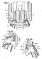
- FIG 11illustrates a possible embodiment where an anchoring table 53 is mounted which is connected to the rotating body 11, in the bottom thereof.
- the anchoring table 53has pick-up attachments 54 which are provided with a larger diameter than the rotating body 11, with the result that, due to the fact that they are suspended in the pick-up attachments 54 in the table 53, the mooring cables 21 acquire a larger lever arm relative to the rotating body 11.
- vertical guides 55are illustrated for lifting means 56 for raising the anchoring table 53 towards the rotating part 11.
- connecting means 57see figures 12 and 13 .
- the risers 22are connected to the anchoring table 53, and in the rotating body 11 are mounted suitable coupling ends 58 for interaction with the risers 22 when they are raised together with the table 53.
- the anchoring tablemay be connected to the rotating body in several possible ways: it may be welded in against the rotating body at the shipyard; it may be attached to the rotating body via a bolted/mounted connection, which enables everything to be easily dismantled; it may be pulled in towards the rotating body in the field and connected to the rotating body manually from the ship; or it may be connected up in a more remotely controlled manner.
- the anchoring table 53 with associated riser 22is located anchored submerged in the water when the ship 1 is moved in over it.
- the lifting means (wires) 55are attached to the anchoring table 53, and by means of winches (not shown) the anchoring table 53 is raised and connected with the rotating body 11 by means of the couplings 57 illustrated in figures 12 and 13 .
- the same or a similar winch arrangement as in figure 1may, for example, be employed.
- the couplings 57contain rotatably mounted claws 59, which by means of working cylinders 60 can be brought into engagement with cut-outs inside the anchoring table 53.
- the anchoring table 53In order to keep the anchoring table 53 afloat, submerged in the water, before connection, the anchoring table 53 is attached to a buoy, as can be seen, for. example, in figure 7 or 9 .
- a buoy 62is provided on the upper side of the anchoring table 53.
- a wire 63(or several) is lowered from the ship from a non-illustrated ship's crane to the buoy 62.
- the lifting means 56(not shown) are attached to the anchoring table 53, in this case by being connected to the wires 64.
- the buoy 62is inflated.
- the buoy 62can be neutralised and released from the anchoring table 53, suspended in the wire 63.
- the buoy 62can then be moved sideways in a controlled manner and away into the water (not shown), whereupon the anchoring table 53 can be raised by the lifting means 56 and connected to the rotating body 11, as shown in figures 11-13 .
- the buoy 65is arranged under the table 53 and accompanies the anchoring table 53 up towards the rotating body 11 after the wires 56 are connected. In this case too the buoy's buoyancy can be controlled with air and water, as will be known to a person skilled in the art.
- the risers 22are passed through the buoy 65.
Landscapes
- Chemical & Material Sciences (AREA)
- Engineering & Computer Science (AREA)
- Combustion & Propulsion (AREA)
- Mechanical Engineering (AREA)
- Ocean & Marine Engineering (AREA)
- Earth Drilling (AREA)
- Sealing Of Bearings (AREA)
- Sliding-Contact Bearings (AREA)
- Sealing Devices (AREA)
- Laying Of Electric Cables Or Lines Outside (AREA)
- Other Liquid Machine Or Engine Such As Wave Power Use (AREA)
Description
- The present invention relates to offshore production of hydrocarbons with the use of a geostationarily anchored vessel. Such a vessel is anchored to the seabed via a body rotatably mounted in the vessel, a so-called turret, from which mooring cables extend to the seabed. From below the vessel risers also ascend through the rotatable body. These risers are connected to a fluid manifold mounted above the rotatable body, from which lines extend for transferring fluid to tanks on board the vessel.
- An object of the invention is to provide an improved geostationary anchoring and riser arrangement on a ship, particularly a converted tanker.
- The invention is specially developed in connection with a conversion of a tanker as specified in the parallel patent application from the same applicant: "Method for conversion of a tanker", published as
WO 2007/089159 , but is not limited to use in connection therewith. The use of the solution according to the invention may well be envisaged in new systems or as a replacement for existing bearing systems. According to the aforementioned parallel application a tanker is provided with a hull containing tanks. In the hull, in one or more tanks, a vertical opening is made, structural elements in the hull, such as frames and stiffeners, being cut and parts of the projected opening removed. A cassette-like structure (cassette) with plate elements is provided designed to fit and connect with the said cut structural elements in the vertical opening, which cassette has a vertical, through-going shaft. The cassette is inserted in the cut-out vertical opening in the hull and connected via the plate elements with the cut structural elements, thereby forming a structure which is incorporated in the hull and forms part of the strength of the surrounding hull. A body is rotatably mounted about a vertical axis in the vertical shaft. The cassette is incorporated in the existing hull in such a manner that the hull's strength is not impaired. - The vertical shaft may advantageously be provided with a lower cylindrical section and an upper cylindrical section extended relative to the lower section, which lower cylindrical section in the cassette's incorporated state will be located near or in the hull's bottom area, the body being rotatably mounted in the transition between the two sections.
- By mounting the said body in the transition between the two sections, far down in the hull, preferably near the hull's bottom area, the hull strength that exists in the hull's bottom area is exploited in an advantageous manner.
- At the top of the said body a fluid manifold may advantageously be located in the shaft.
- This offers the possibility of mounting the fluid manifold in a protected position under the vessel's main deck, in a dry working space in the upper part of the shaft.
- The geostationary anchoring and riser arrangement in a vessel according to the invention comprises a body mounted in a vertical shaft in the vessel, which body is rotatably mounted in a wet vessel area about a vertical axis by means of axial and radial, segmented annular bearings, which body has a top side and a bottom side, vertical guides for risers, between top and bottom side, and is provided with an overlying fluid manifold connected to the risers, the arrangement being characterised in that above the said axial/radial bearing there is mounted a dynamic primary seal between the body and the shaft, and that under the said axial/radial bearing there is mounted a secondary seal between the body and the shaft.
- The dynamic primary seal permits the space in the shaft above the rotatably mounted body (turret) to be maintained as a dry space, where the fluid manifold can be mounted and to which personnel can have access. The secondary seal is preferably a static seal which only comes into effect when the dynamic primary seal is neutralised in order to provide access to the axial/radial bearing for maintenance and other work.
- The mooring cables may be connected to the rotatably mounted body via a structure (anchoring table), thereby obtaining a larger respective lever arm for the mooring cables relative to the body.
- A fluid manifold column may particularly advantageously be supported in the shaft by a central stem projecting from the body's top side. This central stem is advantageously provided with an encircling operating deck above the body's top side, and the individual riser is advantageously connected to a suitable block with an ESD (emergency shut-down) valve on a level with the operating deck.
- In an advantageous embodiment the body rotatably mounted about a vertical axis is characterised in that it is constructed as a cylindrical plate structure with a top side and a bottom side, with a central stem projecting from the bottom side up through the top side and round the stem, between the bottom side and the top side, distributed casings for risers, which stem is designed to support the fluid manifold.
- The support for a body in a vertical shaft in a vessel comprises a segmented annular bearing with adjustable bearing segments, characterised in that the individual bearing segment contains a wearing part against the body, which wearing part may be pressure-lubricated, an intermediate part with a degree of resilience, and a mechanical height-adjustable bottom part against the shaft/the vessel.
- Such a design of the individual bearing segment permits it to be adapted to uneven patches in the hull as well as to the hull movements that occur at sea. The mechanically height-adjustable bottom part in the bearing segment permits adjustments to be made during both mounting and dismantling of the bearing segment. Thus by shifting a bearing segment the bottom part can be adjusted so that the load on the bearing segment is relieved relative to the body, thereby permitting it to be easily removed and reinserted or replaced with a new one.
- A specially preferred mechanically height-adjustable embodiment of the bottom part is one where the bottom part contains interacting wedges movable relative to each other for the said height adjustment. By moving the wedges relative to each other, the desired adjustment of the bearing segment's height can be achieved. Devices other than a wedge solution may be envisaged for adjusting the bearing segments' height.
- In a specially advantageous embodiment the bearing may be disposed in a system for pressure feed of a medium suitable for lubrication of the bearing's bearing segments.
- The lubricating medium may, for example, be known per se lubricants, but may also advantageously be pressurised water, particularly when a certain "lift" of the body relative to the annular bearing is required, a film being formed between the body and the bearing segments. The pressure lubrication is important for preventing too much "drag" of the rotatable body when the vessel rotates under the influence of wind and weather. For water lubrication in particular it is an advantage that it is performed in a wet area, basically open to the sea.
- The invention will now be explained in more detail with reference to the drawing, in which:
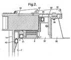
Fig. 1 is a section of a cross section through a converted tanker with the anchoring and riser arrangement,Fig. 2 is a section through the axial and radial bearing of the rotatable body, with primary seal and secondary seal,Fig. 3 is a perspective section viewed from above of the axial and radial annular bearings respectively infig. 2 ,Fig. 4 is a section viewed from above of the bearing infigs. 2 and3 ,Fig. 5 is an isometric view of a bearing segment according to the invention,Fig. 6 is a section through the bearing segment infig. 5 ,Fig. 7 illustrates the front part of a converted tanker, with an anchoring table mounted under the ship,Fig. 8 illustrates the anchoring table with buoy, on a larger scale,Fig. 9 illustrates the front part of a converted tanker, with a modified anchoring table mounted under the ship,Fig. 10 illustrates the anchoring table infigure 9 , on a larger scale,Fig. 11 is a section through the vertical shaft in a ship, with rotating body and connected anchoring table,Figs. 12 and 13 are respective detail sections illustrating a possible interlocking of rotating body and anchoring table.- In
fig. 1 therotatable body 11 is depicted set in position in avertical shaft 6 in a ship'shull 1. Theshaft 6 may be provided in a cassette 5 which is incorporated in thehull 1, as described in the parallel patent application mentioned at the beginning. - The
body 11 has abottom side 12 and atop side 13 and, as illustrated infig. 1 , is constructed as a cylindrical plate structure with anexternal cylinder 14 and acentral stem 15 extending from the body's 11bottom side 12 up through thetop side 13. Infig. 1 there are illustrated two horizontalannular plates central stem 15 and theexternal cylinder 14. Stiffeners and other structural elements known to a person skilled in the art are not shown. Thebody 11 may of course be constructed in other ways which will be well-known to the skilled person. - At its
top side 13 thebody 11 has aflange 18, see alsofig. 2 . Thisflange 18 is used for the rotational mounting of thebody 11, as illustrated infig. 2 . This will be described in more detail below. - In the annular space between the
central stem 15 and theexternal cylinder 14, thebody 11 has a number ofcasings mooring cables 21 andrisers 22 respectively. - The
mooring cables 21 are tightened by means of awinch 23 on the vessel'sdeck 24. On the deck are mounted a number of cable guides 25 (only one is illustrated infig. 1 ), thus enabling themooring cables 21 to be operated by one and thesame winch 23. Themooring cables 21 are suspended in a manner not shown in greater detail at 26 on the body's 11top side 13, with the result that the mooring cables do not extend up into the shaft after anchoring is accomplished. - The
individual risers 22 ascend to arespective valve block 27 mounted on the top of thecentral stem 15. Eachsuch valve block 27 comprises an ESD (emergency shut-down) valve. - On the
central stem 15 is mounted afluid manifold column 28, from whichfluid lines 29 extend to the tanks on board the vessel. - Round the
central stem 15 there is also provided anoperating deck 30. - The space in the
shaft 6 above the body's 11top side 13 is dry. Thebody 11 is arranged in the tanker's bottom area, and is considered to be a wet area. - We now refer to
fig. 2 and succeedingfigures 3-6 for an account of the body's 11 mounting in theshaft 6. In the transition between the shaft'slower section 7 and the shaft'supper section 8 there is provided a packing and bearing arrangement, comprising a segmented axialannular bearing 31 and a segmented radialannular bearing 32. Theaxial bearing 31 has a number ofbearing segments 33. The radialannular bearing 32 also includesbearing segments 34, in this case a smaller number (half) than the bearingsegments 33 in the axial bearing. - Above the two
annular bearings primary seal 35 between the body's 11flange 18 and aconsole 36. Above this dynamic primary seal is mounted a back-upbearing 37, in order to prevent therotatable body 11 from being lifted up. This back-up bearing 37 forms a part ofseveral plate segments 38 that are screwed to theconsole 36 by a number ofscrews 39, see alsofig. 3 . Theplate elements 38 are provided with connectingflanges 40 which can be screwed together with the connecting flanges on adjacent plate elements, thereby forming an encircling deck shield. - Under the
flange 18 is mounted asecondary seal 41. This is intended to only be activated during inspection/replacement of the bearingelements seal 42. This is only intended for use if thesecondary seal 41 has to be replaced, in which case, therefore, it is only a matter of a mounting seal. - As mentioned above, the two
annular bearings segments bearing segment 33 will be described in detail below, with reference tofigs. 5 and 6 . - As illustrated in
figs. 5 and 6 , the bearingsegment 33 is composed of abox 43 on which are mounted an upper wearingpart 44, anintermediate part 45 and a height-adjustable bottom part 46, consisting of two interactingwedge elements part 44 is made of a suitable material, which will be well-known to a person skilled in the art, and theintermediate part 45 is advantageously made of a reinforced rubber material, which will provide a degree of resilience. Thewedges elements 49 only outlined infig. 10 . By altering the relative position of the wedge elements, the height of the bearingsegment 33 can be adjusted. - The bearing
segment 33 is envisaged provided with pressure lubrication, as indicated by thepipe 50, from whichbranch pipes 51 extend tocruciform grooves 52 in the wearingpart 44. As already mentioned, pressurised water lubrication may be employed to particular advantage. - It should be mentioned at this point that the bearing segments can operate in several modes depending on the operating conditions; passive without any kind of lubrication, standard slide bearing; slide bearing with the capability of injecting grease; active pressure lubrication by injecting a medium, typically water, which provides separation of the surfaces, i.e. a hydrostatic bearing.
- The
body 11 is also mounted at the ship's bottom in a known per se manner. The lower radial bearing is not shown, but it too is in the form of a segmented annular bearing. In order to reduce the body's 11 non-circularity to a minimum, it will be advantageous to mount a machined stainless steel ring at the bearing point. The steel ring will ensure a uniform and continuous load distribution round the body's 11 circumference. In order to protect the steel ring against corrosion, a cathodic protective system is provided. - It is a significant advantage that there is access for inspection, adjustment and replacement of all bearings and their segments.
- In
figure 1 mooring cables and risers are passed up through guides in the rotatably mountedbody 11. It is known that the rotatingbody 11, as a geostationarily mounted body, will have a tendency to follow the ship's rotation under the influence of wind and weather or when the ship rotates under the influence of a DP-system (dynamic positioning). This is due to the inertia in the mounting of the rotating body. One way of avoiding this is to have a driving unit in the rotating body, thus enabling it to be turned positively. Another way is to provide larger lever arms for the mooring cables, where they are connected to the rotating body, i.e. at the lower annular bearing for the rotating body in the shaft. Figure 11 illustrates a possible embodiment where an anchoring table 53 is mounted which is connected to therotating body 11, in the bottom thereof. The anchoring table 53 has pick-upattachments 54 which are provided with a larger diameter than the rotatingbody 11, with the result that, due to the fact that they are suspended in the pick-upattachments 54 in the table 53, themooring cables 21 acquire a larger lever arm relative to therotating body 11. Infigure 11 vertical guides 55 are illustrated for lifting means 56 for raising the anchoring table 53 towards the rotatingpart 11. Between therotating part 11 and the anchoring table 53 are provided connectingmeans 57, seefigures 12 and 13 . Therisers 22 are connected to the anchoring table 53, and in therotating body 11 are mounted suitable coupling ends 58 for interaction with therisers 22 when they are raised together with the table 53.- The anchoring table may be connected to the rotating body in several possible ways: it may be welded in against the rotating body at the shipyard; it may be attached to the rotating body via a bolted/mounted connection, which enables everything to be easily dismantled; it may be pulled in towards the rotating body in the field and connected to the rotating body manually from the ship; or it may be connected up in a more remotely controlled manner.
- The anchoring table 53 with associated
riser 22 is located anchored submerged in the water when theship 1 is moved in over it. The lifting means (wires) 55 are attached to the anchoring table 53, and by means of winches (not shown) the anchoring table 53 is raised and connected with the rotatingbody 11 by means of thecouplings 57 illustrated infigures 12 and 13 . The same or a similar winch arrangement as infigure 1 may, for example, be employed. Thecouplings 57 contain rotatably mountedclaws 59, which by means of workingcylinders 60 can be brought into engagement with cut-outs inside the anchoring table 53. - In order to keep the anchoring table 53 afloat, submerged in the water, before connection, the anchoring table 53 is attached to a buoy, as can be seen, for. example, in
figure 7 or9 . - In
figure 7 abuoy 62 is provided on the upper side of the anchoring table 53. When connection between therotating body 11 and the anchoring table 53 is to be undertaken, a wire 63 (or several) is lowered from the ship from a non-illustrated ship's crane to thebuoy 62. The lifting means 56 (not shown) are attached to the anchoring table 53, in this case by being connected to thewires 64. Thebuoy 62 is inflated. By a controlled release of air from and introduction of water into thebuoy 62, after the anchoring table 53 is attached to the lifting means 56, thebuoy 62 can be neutralised and released from the anchoring table 53, suspended in thewire 63. Thebuoy 62 can then be moved sideways in a controlled manner and away into the water (not shown), whereupon the anchoring table 53 can be raised by the lifting means 56 and connected to therotating body 11, as shown infigures 11-13 . - In
figure 9 thebuoy 65 is arranged under the table 53 and accompanies the anchoring table 53 up towards the rotatingbody 11 after thewires 56 are connected. In this case too the buoy's buoyancy can be controlled with air and water, as will be known to a person skilled in the art. Here, therisers 22 are passed through thebuoy 65. - It will be apparent from
figures 7 and9 that the anchoring and riser arrangement, as known, is arranged near forward perpendicular, where the ship's 1 beam moment and deformations are small, while sufficient structural strength is retained. - The invention has now been explained with non-limiting embodiments. A skilled person will appreciate that a multiplicity of changes and modifications can be made with regard to the described embodiments which are within the scope of the invention as defined in the following claims.
Claims (10)
- A geostationary anchoring and riser arrangement in a vessel comprising a body (11), which in a wet vessel area is rotatably mounted about a vertical axis by means of axial and radial, segmented annular bearings (31, 32) to the vessel, which body (11) has a top side (13) and a bottom side (12), guides (19, 20) for risers (22) between the top side (13) and the bottom side (12), is provided with an overlying fluid manifold (28) connected to the risers (22), and is anchored to the seabed by a number of mooring cables (21),
characterised by a dynamic primary seal (35) between the body (11) and the vessel, above the said axial/radial bearing (31, 32), and by a secondary seal (41) between the body (11) and the vessel, under the said bearing (31, 32). - A geostationary anchoring and riser arrangement according to claim 1,
characterised in that the mooring cables (21) are connected to an anchoring table (53) mounted under the body (11) at points (54) which have a larger diameter than the body (11). - A geostationary anchoring and riser arrangement according to claim 2,
characterised in that the anchoring table (53) is attached to a buoy (62;65), thereby enabling it to float submerged in the water when it is not connected to the body (11). - A geostationary anchoring and riser arrangement according to claims 1-3,
characterised in that a fluid manifold column (28) is supported by a central stem (15) projecting from the body's (11) top side (13). - A geostationary anchoring and riser arrangement according to one of the preceding claims,
characterised in that the central stem (15) supports an encircling operating deck (30) above the body's (11) top side (13). - A geostationary anchoring and riser arrangement according to claim 5,
characterised in that each riser (22) is connected to a block (27) with an ESD (emergency shut-down) valve on a level with the operating deck (30). - A geostationary anchoring and riser arrangement according to one of the claims 1-6,
characterised in that the body (11) is constructed as a cylindrical plate structure with a top side (13) and a bottom side (12), with a central stem (15) projecting from the bottom side (12) up through the top side (13) and round the stem (15), between the bottom side (12) and the top side (13), distributed casings (19, 20) for risers (22), which stem (15) is designed to support the fluid manifold (28). - A geostationary anchoring and riser arrangement according to one of the claims 1-7,
characterised in that at least one of the segmented annular bearings (31, 32) comprises a bearing segment (33, 34) comprising a wearing part (44) against the body (11), which wearing part (44) may be pressure lubricated, an intermediate part (45) with a certain degree of resilience, and a height-adjustable bottom part (46) against the vessel. - A geostationary anchoring and riser arrangement according to claim 8,
characterised in that the bottom part (46) comprises interacting wedges (47, 48) which can be moved relative to each other for the said height adjustment. - A geostationary anchoring and riser arrangement according to claim 8 or 9,
characterised in that a system is provided for pressure feed of a suitable medium for lubrication of the bearing's bearing segments (33, 34).
Applications Claiming Priority (2)
| Application Number | Priority Date | Filing Date | Title |
|---|---|---|---|
| NO20060547ANO332014B1 (en) | 2006-02-02 | 2006-02-02 | Geostated docking and riser arrangement in a vessel |
| PCT/NO2007/000033WO2007089157A1 (en) | 2006-02-02 | 2007-02-01 | Geostationary anchoring and riser arrangement on a ship |
Publications (3)
| Publication Number | Publication Date |
|---|---|
| EP1981753A1 EP1981753A1 (en) | 2008-10-22 |
| EP1981753A4 EP1981753A4 (en) | 2014-05-07 |
| EP1981753B1true EP1981753B1 (en) | 2015-06-10 |
Family
ID=38327658
Family Applications (1)
| Application Number | Title | Priority Date | Filing Date |
|---|---|---|---|
| EP07709216.1AActiveEP1981753B1 (en) | 2006-02-02 | 2007-02-01 | Geostationary anchoring and riser arrangement on a ship |
Country Status (9)
| Country | Link |
|---|---|
| US (1) | US8061291B2 (en) |
| EP (1) | EP1981753B1 (en) |
| CN (1) | CN101378953B (en) |
| AU (1) | AU2007210321B2 (en) |
| BR (1) | BRPI0707466A2 (en) |
| CA (1) | CA2638011C (en) |
| NO (1) | NO332014B1 (en) |
| RU (1) | RU2416544C2 (en) |
| WO (1) | WO2007089157A1 (en) |
Families Citing this family (2)
| Publication number | Priority date | Publication date | Assignee | Title |
|---|---|---|---|---|
| FR2928898B1 (en)* | 2008-03-21 | 2010-04-16 | Saipem Sa | FLOATING SUPPORT COMPRISING A TURRET EQUIPPED WITH A MOORING BUOY FOR DOWNLINK / DECKABLE SURFACE LINK PIPES |
| NL1038599C2 (en)* | 2011-02-22 | 2012-08-24 | Baan | Turret mooring with disconnectable submerged buoy with interconnected vertically sliding riser tubes. |
Family Cites Families (11)
| Publication number | Priority date | Publication date | Assignee | Title |
|---|---|---|---|---|
| US4601252A (en)* | 1984-01-03 | 1986-07-22 | Hermann Wuttudal | Turret for mooring VLCC size vessels |
| NO160914C (en)* | 1986-03-24 | 1989-06-14 | Svensen Niels Alf | BUILDING LOADING SYSTEM FOR OFFSHORE PETROLEUM PRODUCTION. |
| US5316509A (en)* | 1991-09-27 | 1994-05-31 | Sofec, Inc. | Disconnectable mooring system |
| US5346314A (en)* | 1993-01-21 | 1994-09-13 | Single Buoy Moorings, Inc. | Bearing assembly and vessel turret assembly |
| NO309933B1 (en)* | 1995-08-07 | 2001-04-23 | Norske Stats Oljeselskap | Multipurpose swivel |
| US5893784A (en)* | 1996-06-17 | 1999-04-13 | Fmc Corporation | Bearing support structure for a turret in mooring system and method for its installation |
| NO310506B1 (en)* | 1997-10-08 | 2001-07-16 | Hitec Systems As | Swivel device for ships such as drilling and production vessels |
| US5957076A (en)* | 1997-08-15 | 1999-09-28 | Imodco, Inc. | Offshore turret upper bearing |
| KR100593476B1 (en)* | 1999-08-09 | 2006-06-28 | 에스케이 텔레콤주식회사 | Handoff Method between Upper Cell and Lower Cell in Nested Cell Structure |
| US6502524B1 (en)* | 2000-10-10 | 2003-01-07 | Prosafe Production Pte Ltd. | Turret support system and bearing unit |
| NO313584B1 (en)* | 2001-11-01 | 2002-10-28 | Statoil Asa I & K Ir Pat | Device for supplying cooling water from the lake to a process aboard a turret anchored vessel |
- 2006
- 2006-02-02NONO20060547Apatent/NO332014B1/enunknown
- 2007
- 2007-02-01EPEP07709216.1Apatent/EP1981753B1/enactiveActive
- 2007-02-01WOPCT/NO2007/000033patent/WO2007089157A1/enactiveApplication Filing
- 2007-02-01CACA2638011Apatent/CA2638011C/ennot_activeExpired - Fee Related
- 2007-02-01CNCN2007800042534Apatent/CN101378953B/ennot_activeExpired - Fee Related
- 2007-02-01AUAU2007210321Apatent/AU2007210321B2/ennot_activeCeased
- 2007-02-01RURU2008134855/11Apatent/RU2416544C2/ennot_activeIP Right Cessation
- 2007-02-01BRBRPI0707466-2Apatent/BRPI0707466A2/ennot_activeIP Right Cessation
- 2007-02-01USUS12/162,882patent/US8061291B2/enactiveActive
Also Published As
| Publication number | Publication date |
|---|---|
| RU2416544C2 (en) | 2011-04-20 |
| US8061291B2 (en) | 2011-11-22 |
| AU2007210321A1 (en) | 2007-08-09 |
| RU2008134855A (en) | 2010-03-10 |
| US20090217858A1 (en) | 2009-09-03 |
| EP1981753A1 (en) | 2008-10-22 |
| WO2007089157A1 (en) | 2007-08-09 |
| CA2638011C (en) | 2013-04-02 |
| CA2638011A1 (en) | 2007-08-09 |
| NO332014B1 (en) | 2012-05-21 |
| NO20060547L (en) | 2007-08-03 |
| BRPI0707466A2 (en) | 2011-05-03 |
| CN101378953A (en) | 2009-03-04 |
| CN101378953B (en) | 2011-03-02 |
| AU2007210321B2 (en) | 2011-12-15 |
| EP1981753A4 (en) | 2014-05-07 |
Similar Documents
| Publication | Publication Date | Title |
|---|---|---|
| JP5362819B2 (en) | Separable turret mooring system with rotatable turntable | |
| US4841895A (en) | Mooring system | |
| EP0613440B1 (en) | Loading/unloading buoy | |
| US7614927B2 (en) | Device for loading and/or unloading flowable media | |
| JP2655338B2 (en) | Mooring turret device | |
| KR102349095B1 (en) | External turret having bogie wheels | |
| EP1981753B1 (en) | Geostationary anchoring and riser arrangement on a ship | |
| EP1981752B1 (en) | Method for conversion of a tanker | |
| MX2008009736A (en) | Geostationary anchoring and riser arrangement on a ship | |
| Knudsen et al. | Turret Operations In the North Sea: Experience From Norne And Åsgard A | |
| AU2003201516B2 (en) | Mooring arrangement | |
| BR112016024082B1 (en) | EXTERNAL TOWER ASSEMBLY FOR MOORING A FLOATING VESSEL AND OFFSHORE VESSEL THAT COMPRISES THE EXTERNAL TOWER ASSEMBLY |
Legal Events
| Date | Code | Title | Description |
|---|---|---|---|
| PUAI | Public reference made under article 153(3) epc to a published international application that has entered the european phase | Free format text:ORIGINAL CODE: 0009012 | |
| 17P | Request for examination filed | Effective date:20080902 | |
| AK | Designated contracting states | Kind code of ref document:A1 Designated state(s):AT BE BG CH CY CZ DE DK EE ES FI FR GB GR HU IE IS IT LI LT LU LV MC NL PL PT RO SE SI SK TR | |
| DAX | Request for extension of the european patent (deleted) | ||
| A4 | Supplementary search report drawn up and despatched | Effective date:20140404 | |
| RIC1 | Information provided on ipc code assigned before grant | Ipc:B63B 21/50 20060101AFI20140331BHEP Ipc:B63B 22/02 20060101ALI20140331BHEP | |
| RIC1 | Information provided on ipc code assigned before grant | Ipc:B63B 21/50 20060101AFI20141105BHEP Ipc:B63B 22/02 20060101ALI20141105BHEP | |
| GRAP | Despatch of communication of intention to grant a patent | Free format text:ORIGINAL CODE: EPIDOSNIGR1 | |
| INTG | Intention to grant announced | Effective date:20150107 | |
| GRAS | Grant fee paid | Free format text:ORIGINAL CODE: EPIDOSNIGR3 | |
| GRAA | (expected) grant | Free format text:ORIGINAL CODE: 0009210 | |
| AK | Designated contracting states | Kind code of ref document:B1 Designated state(s):AT BE BG CH CY CZ DE DK EE ES FI FR GB GR HU IE IS IT LI LT LU LV MC NL PL PT RO SE SI SK TR | |
| REG | Reference to a national code | Ref country code:GB Ref legal event code:FG4D | |
| REG | Reference to a national code | Ref country code:CH Ref legal event code:EP | |
| REG | Reference to a national code | Ref country code:AT Ref legal event code:REF Ref document number:730778 Country of ref document:AT Kind code of ref document:T Effective date:20150715 | |
| REG | Reference to a national code | Ref country code:DE Ref legal event code:R096 Ref document number:602007041734 Country of ref document:DE | |
| REG | Reference to a national code | Ref country code:IE Ref legal event code:FG4D | |
| PG25 | Lapsed in a contracting state [announced via postgrant information from national office to epo] | Ref country code:LT Free format text:LAPSE BECAUSE OF FAILURE TO SUBMIT A TRANSLATION OF THE DESCRIPTION OR TO PAY THE FEE WITHIN THE PRESCRIBED TIME-LIMIT Effective date:20150610 Ref country code:ES Free format text:LAPSE BECAUSE OF FAILURE TO SUBMIT A TRANSLATION OF THE DESCRIPTION OR TO PAY THE FEE WITHIN THE PRESCRIBED TIME-LIMIT Effective date:20150610 Ref country code:FI Free format text:LAPSE BECAUSE OF FAILURE TO SUBMIT A TRANSLATION OF THE DESCRIPTION OR TO PAY THE FEE WITHIN THE PRESCRIBED TIME-LIMIT Effective date:20150610 | |
| REG | Reference to a national code | Ref country code:AT Ref legal event code:MK05 Ref document number:730778 Country of ref document:AT Kind code of ref document:T Effective date:20150610 | |
| REG | Reference to a national code | Ref country code:NL Ref legal event code:MP Effective date:20150610 | |
| PG25 | Lapsed in a contracting state [announced via postgrant information from national office to epo] | Ref country code:LV Free format text:LAPSE BECAUSE OF FAILURE TO SUBMIT A TRANSLATION OF THE DESCRIPTION OR TO PAY THE FEE WITHIN THE PRESCRIBED TIME-LIMIT Effective date:20150610 Ref country code:BG Free format text:LAPSE BECAUSE OF FAILURE TO SUBMIT A TRANSLATION OF THE DESCRIPTION OR TO PAY THE FEE WITHIN THE PRESCRIBED TIME-LIMIT Effective date:20150910 Ref country code:GR Free format text:LAPSE BECAUSE OF FAILURE TO SUBMIT A TRANSLATION OF THE DESCRIPTION OR TO PAY THE FEE WITHIN THE PRESCRIBED TIME-LIMIT Effective date:20150911 | |
| PG25 | Lapsed in a contracting state [announced via postgrant information from national office to epo] | Ref country code:EE Free format text:LAPSE BECAUSE OF FAILURE TO SUBMIT A TRANSLATION OF THE DESCRIPTION OR TO PAY THE FEE WITHIN THE PRESCRIBED TIME-LIMIT Effective date:20150610 | |
| PG25 | Lapsed in a contracting state [announced via postgrant information from national office to epo] | Ref country code:IS Free format text:LAPSE BECAUSE OF FAILURE TO SUBMIT A TRANSLATION OF THE DESCRIPTION OR TO PAY THE FEE WITHIN THE PRESCRIBED TIME-LIMIT Effective date:20151010 Ref country code:CZ Free format text:LAPSE BECAUSE OF FAILURE TO SUBMIT A TRANSLATION OF THE DESCRIPTION OR TO PAY THE FEE WITHIN THE PRESCRIBED TIME-LIMIT Effective date:20150610 Ref country code:PL Free format text:LAPSE BECAUSE OF FAILURE TO SUBMIT A TRANSLATION OF THE DESCRIPTION OR TO PAY THE FEE WITHIN THE PRESCRIBED TIME-LIMIT Effective date:20150610 Ref country code:RO Free format text:LAPSE BECAUSE OF NON-PAYMENT OF DUE FEES Effective date:20150610 Ref country code:AT Free format text:LAPSE BECAUSE OF FAILURE TO SUBMIT A TRANSLATION OF THE DESCRIPTION OR TO PAY THE FEE WITHIN THE PRESCRIBED TIME-LIMIT Effective date:20150610 Ref country code:PT Free format text:LAPSE BECAUSE OF FAILURE TO SUBMIT A TRANSLATION OF THE DESCRIPTION OR TO PAY THE FEE WITHIN THE PRESCRIBED TIME-LIMIT Effective date:20151012 Ref country code:SK Free format text:LAPSE BECAUSE OF FAILURE TO SUBMIT A TRANSLATION OF THE DESCRIPTION OR TO PAY THE FEE WITHIN THE PRESCRIBED TIME-LIMIT Effective date:20150610 | |
| REG | Reference to a national code | Ref country code:DE Ref legal event code:R097 Ref document number:602007041734 Country of ref document:DE | |
| PLBE | No opposition filed within time limit | Free format text:ORIGINAL CODE: 0009261 | |
| STAA | Information on the status of an ep patent application or granted ep patent | Free format text:STATUS: NO OPPOSITION FILED WITHIN TIME LIMIT | |
| PG25 | Lapsed in a contracting state [announced via postgrant information from national office to epo] | Ref country code:DK Free format text:LAPSE BECAUSE OF FAILURE TO SUBMIT A TRANSLATION OF THE DESCRIPTION OR TO PAY THE FEE WITHIN THE PRESCRIBED TIME-LIMIT Effective date:20150610 Ref country code:IT Free format text:LAPSE BECAUSE OF FAILURE TO SUBMIT A TRANSLATION OF THE DESCRIPTION OR TO PAY THE FEE WITHIN THE PRESCRIBED TIME-LIMIT Effective date:20150610 | |
| 26N | No opposition filed | Effective date:20160311 | |
| PG25 | Lapsed in a contracting state [announced via postgrant information from national office to epo] | Ref country code:SI Free format text:LAPSE BECAUSE OF FAILURE TO SUBMIT A TRANSLATION OF THE DESCRIPTION OR TO PAY THE FEE WITHIN THE PRESCRIBED TIME-LIMIT Effective date:20150610 Ref country code:BE Free format text:LAPSE BECAUSE OF NON-PAYMENT OF DUE FEES Effective date:20160229 | |
| REG | Reference to a national code | Ref country code:DE Ref legal event code:R119 Ref document number:602007041734 Country of ref document:DE | |
| PG25 | Lapsed in a contracting state [announced via postgrant information from national office to epo] | Ref country code:LU Free format text:LAPSE BECAUSE OF FAILURE TO SUBMIT A TRANSLATION OF THE DESCRIPTION OR TO PAY THE FEE WITHIN THE PRESCRIBED TIME-LIMIT Effective date:20160201 Ref country code:MC Free format text:LAPSE BECAUSE OF FAILURE TO SUBMIT A TRANSLATION OF THE DESCRIPTION OR TO PAY THE FEE WITHIN THE PRESCRIBED TIME-LIMIT Effective date:20150610 | |
| REG | Reference to a national code | Ref country code:CH Ref legal event code:PL | |
| PG25 | Lapsed in a contracting state [announced via postgrant information from national office to epo] | Ref country code:CH Free format text:LAPSE BECAUSE OF NON-PAYMENT OF DUE FEES Effective date:20160229 Ref country code:LI Free format text:LAPSE BECAUSE OF NON-PAYMENT OF DUE FEES Effective date:20160229 | |
| REG | Reference to a national code | Ref country code:FR Ref legal event code:ST Effective date:20161028 | |
| REG | Reference to a national code | Ref country code:IE Ref legal event code:MM4A | |
| PG25 | Lapsed in a contracting state [announced via postgrant information from national office to epo] | Ref country code:BE Free format text:LAPSE BECAUSE OF FAILURE TO SUBMIT A TRANSLATION OF THE DESCRIPTION OR TO PAY THE FEE WITHIN THE PRESCRIBED TIME-LIMIT Effective date:20150610 | |
| PG25 | Lapsed in a contracting state [announced via postgrant information from national office to epo] | Ref country code:FR Free format text:LAPSE BECAUSE OF NON-PAYMENT OF DUE FEES Effective date:20160229 Ref country code:IE Free format text:LAPSE BECAUSE OF NON-PAYMENT OF DUE FEES Effective date:20160201 Ref country code:DE Free format text:LAPSE BECAUSE OF NON-PAYMENT OF DUE FEES Effective date:20160901 | |
| PG25 | Lapsed in a contracting state [announced via postgrant information from national office to epo] | Ref country code:NL Free format text:LAPSE BECAUSE OF FAILURE TO SUBMIT A TRANSLATION OF THE DESCRIPTION OR TO PAY THE FEE WITHIN THE PRESCRIBED TIME-LIMIT Effective date:20150610 Ref country code:SE Free format text:LAPSE BECAUSE OF FAILURE TO SUBMIT A TRANSLATION OF THE DESCRIPTION OR TO PAY THE FEE WITHIN THE PRESCRIBED TIME-LIMIT Effective date:20150610 | |
| PG25 | Lapsed in a contracting state [announced via postgrant information from national office to epo] | Ref country code:CY Free format text:LAPSE BECAUSE OF FAILURE TO SUBMIT A TRANSLATION OF THE DESCRIPTION OR TO PAY THE FEE WITHIN THE PRESCRIBED TIME-LIMIT Effective date:20150610 Ref country code:HU Free format text:LAPSE BECAUSE OF FAILURE TO SUBMIT A TRANSLATION OF THE DESCRIPTION OR TO PAY THE FEE WITHIN THE PRESCRIBED TIME-LIMIT; INVALID AB INITIO Effective date:20070201 | |
| PG25 | Lapsed in a contracting state [announced via postgrant information from national office to epo] | Ref country code:TR Free format text:LAPSE BECAUSE OF FAILURE TO SUBMIT A TRANSLATION OF THE DESCRIPTION OR TO PAY THE FEE WITHIN THE PRESCRIBED TIME-LIMIT Effective date:20150610 | |
| PGFP | Annual fee paid to national office [announced via postgrant information from national office to epo] | Ref country code:GB Payment date:20241212 Year of fee payment:19 |