EP1980785A1 - Lighting system - Google Patents
Lighting systemDownload PDFInfo
- Publication number
- EP1980785A1 EP1980785A1EP08007182AEP08007182AEP1980785A1EP 1980785 A1EP1980785 A1EP 1980785A1EP 08007182 AEP08007182 AEP 08007182AEP 08007182 AEP08007182 AEP 08007182AEP 1980785 A1EP1980785 A1EP 1980785A1
- Authority
- EP
- European Patent Office
- Prior art keywords
- lamp
- lighting system
- lighting
- units
- plug
- Prior art date
- Legal status (The legal status is an assumption and is not a legal conclusion. Google has not performed a legal analysis and makes no representation as to the accuracy of the status listed.)
- Withdrawn
Links
- 239000011521glassSubstances0.000claimsdescription4
- 239000000463materialSubstances0.000claimsdescription4
- 238000009434installationMethods0.000description22
- 238000010276constructionMethods0.000description6
- 238000005286illuminationMethods0.000description3
- XAGFODPZIPBFFR-UHFFFAOYSA-NaluminiumChemical compound[Al]XAGFODPZIPBFFR-UHFFFAOYSA-N0.000description1
- 229910052782aluminiumInorganic materials0.000description1
- 239000003086colorantSubstances0.000description1
- 238000011161developmentMethods0.000description1
- 230000018109developmental processEffects0.000description1
- 238000004043dyeingMethods0.000description1
- 238000000034methodMethods0.000description1
- 230000001681protective effectEffects0.000description1
- 229910001220stainless steelInorganic materials0.000description1
- 239000010935stainless steelSubstances0.000description1
Images


Classifications
- F—MECHANICAL ENGINEERING; LIGHTING; HEATING; WEAPONS; BLASTING
- F21—LIGHTING
- F21V—FUNCTIONAL FEATURES OR DETAILS OF LIGHTING DEVICES OR SYSTEMS THEREOF; STRUCTURAL COMBINATIONS OF LIGHTING DEVICES WITH OTHER ARTICLES, NOT OTHERWISE PROVIDED FOR
- F21V23/00—Arrangement of electric circuit elements in or on lighting devices
- F21V23/06—Arrangement of electric circuit elements in or on lighting devices the elements being coupling devices, e.g. connectors
- F—MECHANICAL ENGINEERING; LIGHTING; HEATING; WEAPONS; BLASTING
- F21—LIGHTING
- F21S—NON-PORTABLE LIGHTING DEVICES; SYSTEMS THEREOF; VEHICLE LIGHTING DEVICES SPECIALLY ADAPTED FOR VEHICLE EXTERIORS
- F21S2/00—Systems of lighting devices, not provided for in main groups F21S4/00 - F21S10/00 or F21S19/00, e.g. of modular construction
- F21S2/005—Systems of lighting devices, not provided for in main groups F21S4/00 - F21S10/00 or F21S19/00, e.g. of modular construction of modular construction
- F—MECHANICAL ENGINEERING; LIGHTING; HEATING; WEAPONS; BLASTING
- F21—LIGHTING
- F21V—FUNCTIONAL FEATURES OR DETAILS OF LIGHTING DEVICES OR SYSTEMS THEREOF; STRUCTURAL COMBINATIONS OF LIGHTING DEVICES WITH OTHER ARTICLES, NOT OTHERWISE PROVIDED FOR
- F21V21/00—Supporting, suspending, or attaching arrangements for lighting devices; Hand grips
- F21V21/005—Supporting, suspending, or attaching arrangements for lighting devices; Hand grips for several lighting devices in an end-to-end arrangement, i.e. light tracks
- F—MECHANICAL ENGINEERING; LIGHTING; HEATING; WEAPONS; BLASTING
- F21—LIGHTING
- F21S—NON-PORTABLE LIGHTING DEVICES; SYSTEMS THEREOF; VEHICLE LIGHTING DEVICES SPECIALLY ADAPTED FOR VEHICLE EXTERIORS
- F21S8/00—Lighting devices intended for fixed installation
- F21S8/02—Lighting devices intended for fixed installation of recess-mounted type, e.g. downlighters
- F—MECHANICAL ENGINEERING; LIGHTING; HEATING; WEAPONS; BLASTING
- F21—LIGHTING
- F21Y—INDEXING SCHEME ASSOCIATED WITH SUBCLASSES F21K, F21L, F21S and F21V, RELATING TO THE FORM OR THE KIND OF THE LIGHT SOURCES OR OF THE COLOUR OF THE LIGHT EMITTED
- F21Y2115/00—Light-generating elements of semiconductor light sources
- F21Y2115/10—Light-emitting diodes [LED]
Definitions
- the present inventionrelates to a lighting system, comprising a number of electrically interconnectable lighting units, each having at least one lamp board on which a plurality of LED lighting means are arranged.
- Modular constructed lighting systems with a number of electrically interconnectable lighting unitsare already known from the prior art in various embodiments.
- a disadvantage of the known solutionsis that the lamp units are electrically connected to each other in the known lighting systems using cables.
- the wiring of the lighting units in the assembly of such lighting systemsis relatively time-consuming and labor-intensive.
- the present inventionis based on the object to provide a lighting system of the type mentioned, in which the lamp units can be electrically connected to each other during assembly in a simple manner and with little effort.
- a lighting systemcomprises a number of electrically interconnectable lighting units, each having at least one lamp board on which a plurality of LED lighting means are arranged.
- Neighboring lamp units according to the inventionare electrically connected to one another via a plug-in system with a number of plug contacts wirelessly.
- the mounting of the lighting systemcompared to the known from the prior art solutions, in which the electrical connection of adjacent lighting units by means of cables, can be considerably simplified.
- a plurality of lamp units of a LED lampwhich is essentially linear after installation, can be connected to one another wirelessly by means of the plug-in system.
- the modular constructionallows a simple mounting of the lighting system with a plurality of individual lighting units.
- the luminaire system according to the inventioncan be used as an indoor or outdoor luminaire, as a wall, ceiling or floor lamp, as surface or recessed luminaire.
- the lighting systemcan for example be installed in one or more installation channels or mounted on one or more mounting plates.
- a mechanical connection of adjacent lighting unitscan be made available to a certain extent via the plug-in system, so that at least in some installation and assembly situations additional connecting means which mechanically connect adjacent lighting units with one another can be dispensed with.
- each of the lamp boards of a lamp unitcomprises a number of plug pins and sockets, which with the assembly corresponding plug sockets and plug pins of an adjacent lamp unit are connectable. It may be provided in a preferred embodiment that at least some of the connector pins and / or sockets are arranged on the end faces of the lamp boards. There is also the possibility that all connector pins and sockets are arranged on the front sides of the lamp boards. In particular, the plug pins on the one hand and the plug sockets on the other hand can each be arranged on opposite end faces of the lamp boards.
- Each of the lighting units of the lighting systemhas in a preferred embodiment, a profile body, which is designed as a lamp housing. Within the profile body at least one light board is housed in each case.
- the profile bodyare preferably made flat construction, so that the lighting system builds relatively flat overall.
- the light systemin an advantageous embodiment may comprise connecting means, suitable to mechanically connect adjacent lamp units together.
- the connecting meansmay advantageously be designed, for example, as spring locking means, which are formed between two adjacent lighting units. With such a spring lock can be ensured that the lamp units, for example, in a floating (movable in) floor covering always stay in firm contact with each other, so that a proper function of the lighting system is guaranteed.
- the individual LED lighting means of a lighting unitcan be, for example, single-color light-emitting diodes (LEDs); so that a lamp unit emits light with a specific, predetermined wavelength during operation.
- LEDssingle-color light-emitting diodes
- so-called RGB LED bulbscan also be used as LED bulbs.
- At least one of the lamp unitscan thus have a number of RGB lamps.
- Each of the RGB LED illuminantshas a red LED, a green LED and a blue LED, which are arranged close to each other on the luminaire board.
- the luminaire board of at least one of the luminaire unitsmay in a preferred embodiment comprise an RGB light-emitting diode controller for color mixing.
- connection between adjacent lighting unitsare made, as in the embodiments already described above, via a number of plug pins and corresponding plug sockets, which can be arranged in particular on the end faces of the lamp boards.
- plug pins and corresponding plug socketswhich can be arranged in particular on the end faces of the lamp boards.
- a 3-channel data signal with one channel per basic light color red, green and blueis filtered out of the supply line for each individual lighting unit and further processed by the microprocessor. The color mixing is done by dimming the individual RGB colors.
- RGB control modulescan be used.
- the lighting system with RGB color light controlcan be powered by a conventional power supply as in the basic lighting unit (without RGB color light control).
- a 3-channel DMX slave(fully DMX 512 compatible) and an integrated sequencer (works without DMX master) are provided to output specified color sequences.
- each of the lighting unitscomprises an at least partially transparent, essentially plate-shaped cover element.
- the substantially plate-shaped cover elements of the lamp unitsare resistant to treading and, moreover, advantageously also designed to be slip-resistant.
- the cover elementsmay in particular consist of glass.
- a film of a light-directing materialis arranged on the undersides of the cover elements, which point into the interior of the profile body after assembly.
- the lamp boards with the profile bodiesform a preassembled unit.
- the plug-in system 7,by means of which two mutually adjacent lighting units 2 can be electrically connected to each other, is used to power the lighting system 1.
- the length of the light linewhich is formed from the adjacent lighting units 2, with one and the same power supply individually selectable.
- a mechanical connection of adjacent lighting units 2can be made available to a certain extent via the plug-in system 7, so that at least in some installation and assembly situations additional connecting means, which mechanically connect adjacent lighting units 2, can be dispensed with ,
- the lamp units 2each have one, serving as a light housing profile body 3 for receiving a lamp board 4, 4 ', which are each equipped with a plurality of LED bulbs (LEDs 5).
- the LEDs 5 of the lamp units 2can be designed monochrome.
- so-called RGB light-emitting diodescan also be used as LED lamps, at least in some of the lamp units 2.
- an RGB LED controlis then provided, which may be integrated, for example, in one of the lamp units 2.
- the profile body 3 of the lamp units 2can be made in particular of aluminum, plastic or an alternative suitable material.
- Each of the lamp units 2further comprises a substantially plate-shaped cover member 6 for the profile body 3, which may be inserted into the profile body 3 or may be attached to the profile body 3 and at least partially transparent.
- the cover 6is designed anti-slip and can in particular have a slip resistance R12 (according to DIN 51130).
- the cover element 6may in particular be made of a glass which has the slip resistance R12.
- a film (not provided with reference numerals) of a light-directing materialis preferably arranged to improve the illumination of the environment of the light system 1 in operation and appear honiogener allow.
- a lamp board 4is shown according to a first construction variant
- the lamp board 4is made substantially flat and a Variety of LEDs 5 are arranged on the lamp board 4.
- the LEDs 5are arranged offset in this embodiment in two parallel rows to each other.
- the light-emitting diodes 5are arranged distributed in a row, in more than two rows (preferably substantially parallel to one another) or irregularly on the lamp board 4.
- the lighting boards 4 of the lighting units 2can be constructed the same and thus be exchanged with each other in an advantageous manner.
- the plug-in system 7 with plug contactsthe individual lamp boards 4 of the lamp units 2 are assembled into a lighting system 1.
- two pin contactsplug pins 50a, 50b
- two socket contactsplug sockets 51a, 51b
- Each of the lighting boards 4has in this embodiment, about fifty light emitting diodes 5, which are operated with a current of 15 mA.
- a homogeneous, uniform illumination of the cover elements 6 of the light units 2is advantageous.
- an entire (linear) light strip formed from a plurality of lamp units 2should preferably have the same brightness as the lamp boards 4 of the individual lamp units 2.
- On the lamp boards 4more regulators may be arranged, each associated with one of the light emitting diodes 5 to a to achieve uniform brightness of the LEDs 5.
- the luminaire circuit board 4has at a first end face 40 two plug pins 50a, 50b arranged substantially parallel to one another and spaced apart from one another.
- the lamp board 40has two substantially mutually parallel and spaced-apart sockets 51a, 51b.
- the plug pins 50a, 50b and the corresponding sockets 51a, 51b of adjacent lamp units 2thus form the plug-in system 7, by means of which the two adjacent lamp units 2 can be electrically connected to one another wirelessly.
- the plug pins 50a, 50b of one of the lamp units 2 of the lighting system 1respectively engage in the corresponding plug sockets 51a, 51b of an adjacent lamp unit 2 in order to electrically connect the two lamp units 2 to one another.
- the lighting system 1thus consists of individual lighting units 2, which can be wirelessly connected to each other by means of the above-described plug contacts (plug pins 50a, 50b and plug pins 51a, 51b).
- plug pins 50a, 50b and plug pins 51a, 51bThe advantage of the solution proposed here is that the lighting system 1 can be modularly constructed from individual, similarly constructed lighting units 2 and moreover can be easily mounted.
- the lighting system 1furthermore has a voltage supply device, not explicitly shown here, to which the plug pins 50a, 50b of a lighting unit 2 terminating at the end of the mounting of the light system 1 can be connected.
- the voltage supply deviceis variably suitable for a connection of one to n lamp units 2 and preferably has a wide-range input on the primary side, so that it can be operated directly from the electrical supply network.
- the voltage supply devicesupplies a protective extra-low voltage (24 VDC).
- the secondary line the power supply devicecan be connected to a separate feed module 12 during assembly directly to a, the light system 1 after assembly end final lighting unit 2 or, 'as will be explained in more detail below.
- Fig. 7is a lamp board 4 'shown according to a second advantageous construction variant.
- the basic structure of this lamp board 4 'is basically similar to that described above with reference to Fig. 6 has already been explained in more detail.
- the luminaire circuit board 4 'is in turn substantially flat and has a multiplicity of light-emitting diodes 5.
- the LEDs 5are in turn arranged offset in this embodiment in two parallel rows to each other. According to further variants, it is also possible for the LEDs 5 to be distributed in one row, in more than two (preferably substantially parallel) rows, or irregularly distributed on the lamp board 4 '.
- the luminaire plate 4 'in this exemplary embodimenthas no plug pins on the first end face 40.
- Two substantially parallel and mutually offset and spaced plug pins 50a ', 50b'are in the longitudinal direction of the lamp board 4 'axially inwardly, in the region of two recesses 42a, 42b of the lamp board 40' is provided.
- the lamp board 4On the second end face 41, the lamp board 4 'turn two substantially mutually parallel and spaced apart sockets 51 a, 51 b, in which the plug pins 50a, 50b of an adjacent lamp unit 2 can intervene according to the above-explained principle during assembly , Further, the lamp board 4 'has a substantially circular passage opening 43 through which, for example, a electrical connection cable can be performed and can then be connected to the connector pins 50a, 50b:
- the variant of the lamp board 4 'shown hereis thus particularly suitable for a lighting system 2 end of the lamp system 2 after mounting end.
- the luminaire boards 4, 4 'are preferably cast during assembly of the lamp units 2 with the corresponding profile bodies 3.
- the end faces of the profile body 3can each be completed with a transparent end element (not explicitly shown here).
- a closure pieceis attached to the end of the lighting system 1 to the last lamp unit 2, which can protect the free plug-in contact elements of this lamp unit 2.
- the lighting system 1can also be closed on the front side and thus waterproof, so that, for example, electrical short circuits can be effectively prevented.
- Fig. 8is an example of an end view of a lamp unit 2 shown in the in the FIGS. 1 to 7 shown light system 1 can be used.
- the profiled body 3 of the luminaire unit 2 serving as a luminaire housinghas a substantially U-shaped cross section. It also recognizes one of the lighting boards 4, 4 ', which is housed in the profile body 3, and the substantially plate-shaped cover member 6, which covers the profile body 3. Furthermore, the two frontally arranged sockets 51 a, 51 b can be seen, which are suitable for receiving the corresponding connector pins 50a, 50b of a further lamp unit 2.
- the profile body 3is made comparatively flat in this embodiment, so that a structural height of the lamp unit 2 of about 25 mm can be achieved.
- the lamp unit 2 shown hereis particularly suitable for so-called laying floors and allows optimal light control in the cover element preferably made of glass 6.
- the profile body 3 of the lamp unit 2 on opposite longitudinal sidesin each case a mounting guide 8a, 8b, located in Preferably extend longitudinal direction over the entire length or at least almost over the entire length of the profile body 3 and extend substantially orthogonal to the profile walls of the profile body 3 away.
- the mounting guides 8a, 8b formed on the profile wallsare designed for mounting the lamp unit 2 in floor elements (for example laminate or parquet floor elements) which are not explicitly shown here.
- the lateral mounting guides 8a, 8bare suitable for the groove and spring system basically known from the prior art for laying floors.
- connection meansare provided in the area of the front sides of the lamp units 2, which are suitable and arranged for a non-positive and / or a positive mechanical connection of two lamp units 2.
- two spring elements 9a, 9bare arranged on one of the two lateral faces of each of the profile elements 3, which can engage with them during mounting in correspondingly shaped receiving sections of an adjacent lighting unit 2.
- structurally differently designed connecting meanscan be provided as the spring elements 9a, 9b shown here, to two lamp units 2 during assembly non-positively and / or positively with each other connect.
- the mechanical connection of the adjacent lighting units 2can ensure that the lighting units 2 of the lighting system 1 always remain in firm contact with one another in the case of a floating (ie movable) floor covering, so that proper functioning of the lighting system 1 can be ensured.
- FIG. 9 to 12Two further variants of the lighting system 1 will be explained in more detail below.
- the basic system structure of the two variants of the light system 1is comparable to that of the first embodiment.
- a surface mounted luminairewhich can be attached to a wall or ceiling.
- a recessed luminairewhich during installation in a mounting channel 11, the in Fig. 12 is shown, is installed.
- the profile body 3 of the lighting units 2have the same cross-sectional shape.
- the cross section of the profile body 3in turn is substantially U-shaped.
- the profile body 3 serving as a luminaire housinghas a step 30a, 30b on both longitudinal sides, which extends in the longitudinal direction, in order to ensure a tight installation in the mounting channel 11.
- the lighting system 1as in Fig. 9 shown by way of example for the surface-mounted luminaire variant, have an infeed block 12 at the front end via which the luminaire units 2 can be supplied with electric current.
- the feed block 12is first attached to the wall or ceiling or in the mounting channel 11 during assembly of the light system 1 by means of the mounting plate 10 which is screwed to the wall or ceiling.
- the feed block 12serves for making electrical contact with the first lighting unit 2 of the lighting system 1.
- the profile body 3 of the following on the feed block 12 lamp unit 2is pushed onto the mounting plate 10 on the feed block 12.
- the electrical connectiontakes place by means of the end-side plug contact elements already described above (plug pins 50a, 50b or plug sockets 51a, 51b).
- the mounting plate 10takes the respective lamp unit 2 via two correspondingly shaped guides 13a; 13b, which extend in the longitudinal direction over the entire length of the profile body 3.
- next lamp unit 2By screwing the next mounting plate 10 on the wall / ceiling or the inlet channel 11, the next lamp unit 2 is then mounted. This assembly process is repeated until the last lamp unit 2 is connected.
- a closure pieceis mounted, which is the free plug-in contact elements of the last Luminaire unit 2 protects.
- the lighting system 1can be closed on the face side and made watertight, so that, for example, electrical short circuits can be effectively prevented. Furthermore, slippage of the lamp units 2 on the mounting plates 10 can be effectively prevented.
- the variant shownis the length of the installation channel 11, the profile shape of which is adapted to the profile cross section of the profile body 3 of the lamp units 2, regardless of the length of the lamp units 2, so that the installation channel 11 can also be mounted endlessly.
- An extension of the installation channel 11, for example, the next six meterscan be ensured by a plurality of lateral pin guides 14a - 14d.
- two adjacent installation channels 11can be guided by the introduction of commercially executed stainless steel pins or the like and thus an offset of the joint between the two adjacent installation channels 11 can be prevented.
- the built-in channel 11is poured into a wall, ceiling or in a floor.
- the installation channel 11also has one or more screw channels 15 into which a respective mounting screw 16 extending through a bore 17 of the mounting plate 10 can engage in order to fix the lamp unit 2 in the installation channel 11.
- the lamp unit 2 / the lamp units 2 with the help of the installation channel 11 / the installation channels 11can be installed flush in a wall, ceiling or in a floor / can.
- lamp units 2can be provided with different lengths of the profile body 3 in order to be able to individually adapt the overall length of the lighting system 1 by a combination of a plurality of lamp units 2 to the conditions at the installation site.
Landscapes
- Engineering & Computer Science (AREA)
- General Engineering & Computer Science (AREA)
- Non-Portable Lighting Devices Or Systems Thereof (AREA)
- Arrangement Of Elements, Cooling, Sealing, Or The Like Of Lighting Devices (AREA)
Abstract
Description
Translated fromGermanDie vorliegende Erfindung betrifft ein Leuchtensystem, umfassend eine Anzahl elektrisch miteinander verbindbarer Leuchteneinheiten mit jeweils mindestens einer Leuchtenplatine, auf der mehrere LED-Leuchtmittel angeordnet sind.The present invention relates to a lighting system, comprising a number of electrically interconnectable lighting units, each having at least one lamp board on which a plurality of LED lighting means are arranged.
Modular aufgebaute Leuchtensysteme mit einer Anzahl elektrisch miteinander verbindbarer Leuchteneinheiten sind aus dem Stand der Technik in verschiedenen Ausführungsformen bereits bekannt. Ein Nachteil der bekannten Lösungen besteht darin, dass die Leuchteneinheiten bei den bekannten Leuchtensystemen mit Hilfe von Kabeln elektrisch miteinander verbunden werden. Die Verkabelung der Leuchteneinheiten bei der Montage derartiger Leuchtensysteme ist relativ zeit- und arbeitsintensiv.Modular constructed lighting systems with a number of electrically interconnectable lighting units are already known from the prior art in various embodiments. A disadvantage of the known solutions is that the lamp units are electrically connected to each other in the known lighting systems using cables. The wiring of the lighting units in the assembly of such lighting systems is relatively time-consuming and labor-intensive.
Hier setzt die vorliegende Erfindung an.This is where the present invention begins.
Der vorliegenden Erfindung liegt die Aufgabe zu Grunde, ein Leuchtensystem der eingangs genannten Art zur Verfügung zu stellen, bei dem die Leuchteneinheiten bei der Montage auf einfache Weise und mit einem geringen Aufwand elektrisch miteinander verbunden werden können.The present invention is based on the object to provide a lighting system of the type mentioned, in which the lamp units can be electrically connected to each other during assembly in a simple manner and with little effort.
Diese Aufgabe wird durch ein Leuchtensystem der eingangs genannten Art mit mit den Merkmalen des kennzeichnenden Teils des Anspruchs 1 gelöst. Die Unteransprüche betreffen vorteilhafte Weiterbildungen der Erfindung.This object is achieved by a lighting system of the type mentioned with with the features of the characterizing part of
Gemäß Anspruch 1 umfasst ein Leuchtensystem eine Anzahl elektrisch miteinander verbindbarer Leuchteneinheiten mit jeweils mindestens einer Leuchtenplatine, auf der mehrere LED-Leuchtmittel angeordnet sind. Benachbarte Leuchteneinheiten sind bei der Montage erfindungsgemäß über ein Stecksystem mit einer Anzahl von Steckkontakten kabellos elektrisch miteinander verbindbar. Dadurch kann die Montage des Leuchtensystems im Vergleich zu den aus dem Stand der Technik bekannten Lösungen, bei denen die elektrische Verbindung benachbarter Leuchteneinheiten mit Hilfe von Kabeln erfolgt, erheblich vereinfacht werden. Mit Hilfe der hier vorgeschlagenen erfindungsgemäßen Lösung können zum Beispiel mehrere Leuchteneinheiten einer nach der Montage im Wesentlichen linienförmige LED-Leuchte mittels des Stecksystems kabellos miteinander verbunden werden. Der modulare Aufbau ermöglicht insbesondere eine einfache Montage des Leuchtensystems mit einer Mehrzahl einzelner Leuchteneinheiten.According to
Das erfindungsgemäße Leuchtensystem kann als Innen- oder als Außenleuchte, als Wand-, Decken- oder Bodenleuchte, als Anbau- oder Einbauleuchte eingesetzt werden. Das Leuchtensystem kann beispielsweise in einen oder mehrere Einbaukanäle eingebaut oder auf einer oder mehreren Montageplatten montiert werden. Neben der elektrischen Verbindung kann über das Stecksystem bis zu einem gewissen Grad auch eine mechanische Verbindung benachbarter Leuchteneinheiten zur Verfügung gestellt werden, so dass zumindest in einigen Einbau- und Montagesituationen auf zusätzliche Verbindungsmittel, die benachbarte Leuchteneinheiten mechanisch miteinander verbinden, verzichtet werden kann.The luminaire system according to the invention can be used as an indoor or outdoor luminaire, as a wall, ceiling or floor lamp, as surface or recessed luminaire. The lighting system can for example be installed in one or more installation channels or mounted on one or more mounting plates. In addition to the electrical connection, a mechanical connection of adjacent lighting units can be made available to a certain extent via the plug-in system, so that at least in some installation and assembly situations additional connecting means which mechanically connect adjacent lighting units with one another can be dispensed with.
In einer bevorzugten Ausführungsform wird vorgeschlagen, dass jede der Leuchtenplatinen einer Leuchteneinheit eine Anzahl von Steckerstiften und Steckerbuchsen umfasst, die bei der Montage mit korrespondierenden Steckerbuchsen und Steckerstiften einer benachbarten Leuchteneinheit verbindbar sind. Es kann in einer bevorzugten Ausführungsform vorgesehen sein, dass zumindest einige der Steckerstifte und/oder Steckerbuchsen an den Stirnseiten der Leuchtenplatinen angeordnet sind. Es besteht auch die Möglichkeit, dass alle Steckerstifte und Steckerbuchsen an den Stirnseiten der Leuchtenplatinen angeordnet sind.
Insbesondere können die Steckerstifte einerseits und die Steckerbuchsen andererseits jeweils an gegenüberliegenden Stirnseiten der Leuchtenplatinen angeordnet sein.In a preferred embodiment, it is proposed that each of the lamp boards of a lamp unit comprises a number of plug pins and sockets, which with the assembly corresponding plug sockets and plug pins of an adjacent lamp unit are connectable. It may be provided in a preferred embodiment that at least some of the connector pins and / or sockets are arranged on the end faces of the lamp boards. There is also the possibility that all connector pins and sockets are arranged on the front sides of the lamp boards.
In particular, the plug pins on the one hand and the plug sockets on the other hand can each be arranged on opposite end faces of the lamp boards.
Jede der Leuchteneinheiten des Leuchtensystems weist in einer bevorzugten Ausführungsform einen Profilkörper auf, der als Leuchtengehäuse ausgebildet ist. Innerhalb der Profilkörper ist jeweils mindestens eine Leuchtenplatine untergebracht. Die Profilkörper sind vorzugsweise flach bauend ausgeführt, so dass das Leuchtensystem insgesamt relativ flach baut.Each of the lighting units of the lighting system has in a preferred embodiment, a profile body, which is designed as a lamp housing. Within the profile body at least one light board is housed in each case. The profile body are preferably made flat construction, so that the lighting system builds relatively flat overall.
Wenn die Leuchteneinheiten nicht durch Anschrauben oder in sonstiger Weise im Bodenbereich befestigt werden können, kann das Leuchtensystem in einer vorteilhaften Ausführungsform Verbindungsmittel umfassen, geeignet, benachbarte Leuchteneinheiten mechanisch miteinander zu verbinden. Die Verbindungsmittel können vorteilhaft zum Beispiel als Federarretierungsmittel ausgeführt sein, die zwischen zwei benachbarten Leuchteneinheiten ausgebildet sind. Mit einer derartigen Federarretierung kann gewährleistet werden, dass die Leuchteneinheiten zum Beispiel bei einem schwimmenden (in sich bewegbaren) Fußbodenbelag immer in einem festen Kontakt miteinander bleiben, so dass eine einwandfreie Funktion des Leuchtensystems gewährleistet bleibt.If the lamp units can not be fastened by screwing or otherwise in the floor area, the light system in an advantageous embodiment may comprise connecting means, suitable to mechanically connect adjacent lamp units together. The connecting means may advantageously be designed, for example, as spring locking means, which are formed between two adjacent lighting units. With such a spring lock can be ensured that the lamp units, for example, in a floating (movable in) floor covering always stay in firm contact with each other, so that a proper function of the lighting system is guaranteed.
Die einzelnen LED-Leuchtmittel einer Leuchteneinheit können zum Beispiel einfarbige Leuchtdioden (LEDs) sein; so dass eine Leuchteneinheit im Betrieb Licht mit einer bestimmten, vorgegebenen Wellenlänge emittiert. In einer alternativen Ausführungsform können als LED-Leuchtmittel auch so genannte RGB-LED-Leuchtmittel eingesetzt werden. Mindestens eine der Leuchteneinheiten kann somit eine Anzahl von RGB-Leuchtmitteln aufweisen. Jedes der RGB-LED-Leuchtmittel-weist eine rote Leuchtdiode, eine grüne Leuchtdiode sowie eine blaue Leuchtdiode auf, die auf der Leuchtenplatine dicht nebeneinander angeordnet sind. Durch eine geeignete Ansteuerung der drei Leuchtdioden der RGB-LED-Leuchtmittel kann die abgestrahlte Lichtfarbe (Wellenlänge) der entsprechenden Leuchteneinheit gezielt eingestellt werden. Die Leuchtenplatine mindestens einer der Leuchteneinheiten kann in einer bevorzugten Ausführungsform eine RGB-Leuchtdiodensteuerung zur Farbmischung umfassen.The individual LED lighting means of a lighting unit can be, for example, single-color light-emitting diodes (LEDs); so that a lamp unit emits light with a specific, predetermined wavelength during operation. In an alternative embodiment, so-called RGB LED bulbs can also be used as LED bulbs. At least one of the lamp units can thus have a number of RGB lamps. Each of the RGB LED illuminants has a red LED, a green LED and a blue LED, which are arranged close to each other on the luminaire board. By suitable control of the three LEDs of the RGB LED bulbs, the radiated light color (wavelength) of the corresponding lamp unit can be set specifically. The luminaire board of at least one of the luminaire units may in a preferred embodiment comprise an RGB light-emitting diode controller for color mixing.
Da es besonders vorteilhaft ist, Leuchteneinheiten mit Leuchtenplatinen, die für eine RGB-LED-Steuerung zur Farbmischung geeignet sind, mit Leuchteneinheiten mit kostengünstigeren Leuchtenplatinen, die ausschließlich mit einfarbigen Leuchtdioden bestückt sind, zu kombinieren, besteht in einer vorteilhaften Ausführungsform die Möglichkeit, dass der Aufbau der Leuchteneinheiten hinsichtlich der elektrischen Kontaktierung mit einer benachbarten Leuchteneinheit über zwei Steckkontakte zur Stromversorgung identisch ist. Aus diesem Grunde wird in einer vorteilhaften Ausführungsform vorgeschlagen, dass die RGB-Färbansteuerung über die Stromversorgung der Leuchteneinheiten erfolgt. Es besteht somit die Möglichkeit, dass eine RGB-Leuchteneinheit zwischen zwei herkömmlichen (einfarbigen) LED-Leuchteneinheiten installiert werden kann, wobei die Steuerung über die gleiche Stromversorgung erfolgt.Since it is particularly advantageous to combine lighting units with light panels, which are suitable for RGB LED control for color mixing, with light units with less expensive light panels that are equipped exclusively with single-color light-emitting diodes, in an advantageous embodiment, the possibility that the Structure of the lamp units with respect to the electrical contact with an adjacent lamp unit via two plug contacts for power supply is identical. For this reason, it is proposed in an advantageous embodiment that the RGB dyeing control takes place via the power supply of the lighting units. There is thus the possibility that an RGB lighting unit can be installed between two conventional (single-color) LED lighting units, with control being provided by the same power supply.
Folgende Komponenten können beispielsweise auf einer Leuchtenplatine, die für eine RGB-Farbansteuerung geeignet ist, integriert sein:
- DMX - Über 24 V Empfänger (DMX=DigitalMultiplex);
- mikroprozessorgesteuerte Elektronik
- dimmfähige Leistungselektronik
- 50 RGB - Leuchtdioden mit einer Gesamtleistung von etwa 9 Watt
- DMX - About 24 V receiver (DMX =D igitalM ultiplex);
- microprocessor-controlled electronics
- Dimmable power electronics
- 50 RGB LEDs with a total power of about 9 watts
Die Steckverbindungen zwischen benachbarten Leuchteneinheiten erfolgen wie in den oben bereits beschriebenen Ausführungsformen über eine Anzahl von Steckerstiften und damit korrespondierenden Steckerbuchsen, die insbesondere an den Stirnseiten der Leuchtenplatinen angeordnet sein können. Bei dieser Ausführungsform ist es zum Beispiel in vorteilhafter Weise möglich, für die Versorgung und für Steuersignale lediglich eine zweiadrige, nicht abgeschirmte Leitung mit einer Länge von bis zu 20m zu verwenden. Ein 3-kanaliges Datensignal mit einem Kanal pro Basislichtfarbe rot, grün und blau wird bei jeder einzelnen Leuchteneinheit aus der Versorgungsleitung herausgefiltert und durch den Mikroprozessor weiterverarbeitet. Die Farbmischung erfolgt über die Dimmung der einzelnen RGB- Farben.The connections between adjacent lighting units are made, as in the embodiments already described above, via a number of plug pins and corresponding plug sockets, which can be arranged in particular on the end faces of the lamp boards. In this embodiment, for example, it is advantageously possible to use for the supply and for control signals only a two-wire, unshielded wire with a length of up to 20m. A 3-channel data signal with one channel per basic light color red, green and blue is filtered out of the supply line for each individual lighting unit and further processed by the microprocessor. The color mixing is done by dimming the individual RGB colors.
Grundsätzlich können herkömmliche RGB-Steuerungsmodule eingesetzt werden. Die Stromversorgung des Leuchtensystems mit RGB-Farblichtsteuerung kann über ein herkömmliches Netzteil wie bei der Basisleuchteneinheit (ohne RGB-Farblichtsteuerung) erfolgen. Zusätzlich ist ein 3-kanaliger DMX-Slave (voll DMX 512 kompatibel) und ein integrierter Sequenzer (funktioniert ohne DMX-Master) vorgesehen, um festgelegte Farbabläufe auszugeben.In principle, conventional RGB control modules can be used. The lighting system with RGB color light control can be powered by a conventional power supply as in the basic lighting unit (without RGB color light control). In addition, a 3-channel DMX slave (fully DMX 512 compatible) and an integrated sequencer (works without DMX master) are provided to output specified color sequences.
In einer besonders vorteilhaften Ausführungsform wird vorgeschlagen, dass jede der Leuchteneinheiten ein zumindest abschnittsweise transparentes, im Wesentlichen plattenförmiges Abdeckelement umfasst. Vorzugsweise sind die im Wesentlichen plattenförmigen Abdeckelemente der Leuchteneinheiten trittfest und darüber hinaus vorteilhaft auch rutschhemmend ausgeführt. Die Abdeckelemente können insbesondere aus Glas bestehen.In a particularly advantageous embodiment, it is proposed that each of the lighting units comprises an at least partially transparent, essentially plate-shaped cover element. Preferably, the substantially plate-shaped cover elements of the lamp units are resistant to treading and, moreover, advantageously also designed to be slip-resistant. The cover elements may in particular consist of glass.
Um die Ausleuchtung der Umgebung des Leuchtensystems während des Betriebs zu verbessern und homogener erscheinen zu lassen, wird in einer besonders bevorzugten Ausführungsform vorgeschlagen, dass an den Unterseiten der Abdeckelemente, die nach der Montage in das Innere des Profilkörpers weisen, eine Folie aus einem lichtlenkenden Material angeordnet ist.In order to improve the illumination of the surroundings of the lighting system during operation and to make it appear more homogeneous, it is proposed in a particularly preferred embodiment that on the undersides of the cover elements, which point into the interior of the profile body after assembly, a film of a light-directing material is arranged.
Es besteht in einer besonders bevorzugten Ausführungsform die Möglichkeit, dass die Leuchtenplatinen mit den Profilkörpern vergossen sind. Dadurch bilden die Leuchtenplatinen mit den Profilkörpern eine vormontierte Einheit.There is in a particularly preferred embodiment, the possibility that the lamp boards are cast with the profile bodies. As a result, the lamp boards with the profile bodies form a preassembled unit.
Weitere Merkmale und Vorteile der vorliegender, Erfindung werden deutlich anhand der nachfolgenden Beschreibung bevorzugter Ausführungsbeispiele unter Bezugnahme auf die beiliegenden Abbildungen. Darin zeigen
- Fig. 1
- eine Draufsicht auf ein Leuchtensystem gemäß einem ersten Ausführungsbeispiel der vorliegenden Erfindung;
- Fig. 2
- eine Seitenansicht des Leuchtensystems gemäß
Fig. 1 ; - Fig. 3
- eine Einzelheit gemäß III in
Fig. 1 ; - Fig. 4
- eine Einzelheit gemäß IV in
Fig. 2 ; - Fig. 5
- eine perspektivische Darstellung der Steckverbindung zweier Leuchteneinheiten;
- Fig. 6
- eine Draufsicht auf eine Leuchtenplatine gemäß einer ersten Aufbauvariante;
- Fig. 7
- eine Draufsicht auf eine Leuchtenplatine gemäß einer zweiten Aufbauvariante;
- Fig. 8
- eine Stirnseitenansicht einer Leuchteneinheit des Leuchtensystems gemäß dem ersten Ausführungsbeispiel der vorliegenden Erfindung;
- Fig. 9
- eine perspektivische Darstellung eines Leuchtensystems gemäß einem zweiten Ausführungsbeispiel der vorliegenden Erfindung;
- Fig. 10
- einen Querschnitt durch eine Leuchteneinheit des Leuchtensystems gemäß
Fig. 9 ; - Fig. 11
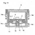
- einen Querschnitt durch eine Leuchteneinheit gemäß einem dritten Ausführungsbeispiel der vorliegenden Erfindung, nach dem Einbau in einen Einbaukanal;
- Fig. 12
- eine schematische Darstellung des Einbaukanals gemäß
Fig. 11 .
- Fig. 1
- a plan view of a lighting system according to a first embodiment of the present invention;
- Fig. 2
- a side view of the lighting system according to
Fig. 1 ; - Fig. 3
- a detail according to III in
Fig. 1 ; - Fig. 4
- a detail according to IV in
Fig. 2 ; - Fig. 5
- a perspective view of the connector of two lamp units;
- Fig. 6
- a plan view of a lamp board according to a first construction variant;
- Fig. 7
- a plan view of a lamp board according to a second construction variant;
- Fig. 8
- an end view of a lamp unit of the lighting system according to the first embodiment of the present invention;
- Fig. 9
- a perspective view of a lighting system according to a second embodiment of the present invention;
- Fig. 10
- a cross section through a lamp unit of the lighting system according to
Fig. 9 ; - Fig. 11
- a cross section through a lamp unit according to a third embodiment of the present invention, after installation in a mounting channel;
- Fig. 12
- a schematic representation of the installation channel according to
Fig. 11 ,
Unter Bezugnahme auf
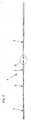
Wie in
Die Leuchteneinheiten 2 weisen jeweils einen, als Leuchtengehäuse dienenden Profilkörper 3 zur Aufnahme einer Leuchtenplatine 4, 4' auf, die jeweils mit einer Mehrzahl von LED-Leuchtmitteln (Leuchtdioden 5) bestückt sind. Die Leuchtdioden 5 der Leuchteneinheiten 2 können einfarbig ausgeführt sein. Zwecks Farbmischung können aber zumindest bei einigen der Leuchteneinheiten 2 auch so genannte RGB-Leuchtdioden als LED-Leuchtmittel eingesetzt werden. Vorzugsweise ist dann auch eine RGB-Leuchtdiodensteuerung vorgesehen, die zum Beispiel in eine der Leuchteneinheiten 2 integriert sein kann.The
Die Profilkörper 3 der Leuchteneinheiten 2 können insbesondere aus Aluminium, aus Kunststoff oder einem alternativen geeigneten Material hergestellt sein. Jede der Leuchteneinheiten 2 weist ferner ein im Wesentlichen plattenförmiges Abdeckelement 6 für den Profilkörper 3 auf, das in den Profilkörper 3 eingesetzt sein kann oder an dem Profilkörper 3 angebracht sein kann und zumindest abschnittsweise transparent ausgeführt ist. Vorzugsweise ist das Abdeckelement 6 rutschhemmend ausgeführt und kann insbesondere eine Rutschhemmung R12 (nach DIN 51130) aufweisen. Das Abdeckelement 6 kann insbesondere aus einem Glas hergestellt sein, welches die Rutschhemmung R12 aufweist. An einer Unterseite des Abdeckelements 6, die nach der Montage in das Innere des Profilkörpers 3 weist, ist vorzugsweise eine Folie (nicht mit Bezugszeichen versehen) aus einem lichtlenkenden Material angeordnet, um die Ausleuchtung der Umgebung des Leuchtensystems 1 im Betrieb zu verbessern und honiogener erscheinen zu lassen.The
Unter Bezugnahme auf
Die Leuchtenplatinen 4 der Leuchteneinheiten 2 können gleich aufgebaut sein und damit in vorteilhafter Weise untereinander ausgetauscht werden. Durch das Stecksystem 7 mit Steckkontakten werden die einzelnen Leuchtenplatinen 4 der Leuchteneinheiten 2 zu einem Leuchtensystem 1 zusammengesetzt. Eingangsseitig sind bei jeder Leuchteneinheit 2 zwei Stiftkontakte (Steckerstifte 50a, 50b) und ausgangsseitig zwei Buchsenkontakte (Steckerbuchsen 51 a, 51 b) vorgesehen.The
Jede der Leuchtenplatinen 4 weist in diesem Ausführungsbeispiel etwa fünfzig Leuchtdioden 5 auf, die mit einem Strom von 15 mA betrieben werden. Bei der Platzierung der Leuchtdioden 5 auf den Leuchtenplatinen 4 ist ein homogenes, gleichmäßiges Ausleuchten der Abdeckelemente 6 der Leuchteneinheiten 2 vorteilhaft. Auch ein gesamtes, aus mehreren Leuchteneinheiten 2 gebildetes (lineares) Leuchtenband sollte vorzugsweise die gleiche Helligkeit aufweisen wie die Leuchtenplatinen 4 der einzelnen Leuchteneinheiten 2. Auf der Leuchtenplatinen 4 können ferner mehrere Regler angeordnet sein, die jeweils einer der Leuchtdioden 5 zugeordnet sind, um eine gleichmäßige Helligkeit der Leuchtdioden 5 zu erreichen.Each of the
Man erkennt, dass die Leuchtenplatine 4 an einer ersten Stirnseite 40 zwei im Wesentlichen parallel zueinander angeordnete und voneinander beabstandete Steckerstifte 50a, 50b aufweist. An der gegenüberliegenden zweiten Stirnseite 41 weist die Leuchtenplatine 40 zwei im Wesentlichen parallel zueinander angeordnete und voneinander beabstandete Steckerbuchsen 51a, 51b auf. Die Steckerstifte 50a, 50b und die korrespondierenden Steckerbuchsen 51 a, 51 b benachbarter Leuchteneinheiten 2 bilden somit das Stecksystem 7, mittels dessen die beiden benachbarten Leuchteneinheiten 2 kabellos elektrisch miteinander verbunden werden können. Bei der Montage greifen also die Steckerstifte 50a, 50b einer der Leuchteneinheiten 2 des Leuchtensystems 1 jeweils in die korrespondierenden Steckerbuchsen 51a, 51b einer benachbarten Leuchteneinheit 2 ein, um beide Leuchteneinheiten 2 elektrisch miteinander zu verbinden.It can be seen that the
Das Leuchtensystem 1 besteht somit aus einzelnen Leuchteneinheiten 2, die mittels der vorstehend beschriebenen Steckkontakte (Steckerstifte 50a, 50b und Steckerstifte 51a, 51b) kabellos miteinander verbunden werden können. Der Vorteil der hier vorgeschlagenen Lösung besteht darin, dass das Leuchtensystem 1 modular aus einzelnen, gleichartig aufgebauten Leuchteneinheiten 2 aufgebaut werden kann und darüber hinaus einfach montiert werden kann.The
Das Leuchtensystem 1 weist ferner eine,hier nicht explizit dargestellte Spannungsversorgungseinrichtung, an die die Steckerstifte 50a, 50b einer, das Leuchtensystem 1 nach der Montage endseitig abschließenden Leuchteneinheit 2 angeschlossen werden können. Die Spannungsversorgungseinrichtung ist variabel für einen Anschluss von einer bis n Leuchteneinheiten 2 geeignet und weist vorzugsweise auf der Primärseite einen Weitbereichseingang auf, so dass sie direkt aus dem elektrischen Versorgungsnetz betrieben werden kann. Auf der Sekundärseite liefert die Spannungsversorgungseinrichtung eine Schutzkleinspannung (24 Volt-Gleichspannung). Die Sekundärleitung der Spannungsversorgungseinrichtung kann bei der Montage direkt an eine, das Leuchtensystem 1 nach der Montage endseitig abschließende Leuchteneinheit 2 oder,'wie weiter unten näher erläutert werden wird, an ein separates Einspeisemodul 12 angeschlossen werden.The
In
Es wird deutlich, dass die Leuchtenplatine 4' in diesem Ausführungsbeispiel an der ersten Stirnseite 40 keine Steckerstifte aufweist. Zwei im Wesentlichen parallele und versetzt zueinander angeordnete und voneinander beabstandete Steckerstifte 50a', 50b' sind in Längsrichtung der Leuchtenplatine 4' axial einwärts, und zwar im Bereich zweier Aussparungen 42a, 42b der Leuchtenplatine 40' vorgesehen. An der zweiten Stirnseite 41 weist die Leuchtenplatine 4' wiederum zwei im Wesentlichen parallel zueinander angeordnete und voneinander beabstandete Steckerbuchsen 51 a, 51 b auf, in die die Steckerstifte 50a, 50b einer benachbarten Leuchteneinheit 2 nach dem oben bereits erläuterten Prinzip bei der Montage eingreifen können. Ferner weist die Leuchtenplatine 4' eine im Wesentlichen kreisförmige Durchgangsöffnung 43 auf, durch die zum Beispiel ein elektrisches Anschlusskabel geführt werden kann und dann an die Steckerstifte 50a, 50b angeschlossen werden kann: Die hier gezeigte Variante der Leuchtenplatine 4' eignet sich somit insbesondere für eine das Leuchtensystem 1 nach der Montage endseitig abschließende Leuchteneinheit 2.It becomes clear that the luminaire plate 4 'in this exemplary embodiment has no plug pins on the
Die Leuchtenplatinen 4, 4' werden beim Zusammenbau der Leuchteneinheiten 2 vorzugsweise mit den entsprechenden Profilkörpern 3 vergossen. Die Stirnseiten der Profilkörper 3 können jeweils mit einem transparenten Abschlusselement (hier nicht explizit gezeigt) abgeschlossen sein. Bei der Montage wird am Ende des Leuchtensystems 1 an der letzten Leuchteneinheit 2 ein Verschlussstück angebracht, welches die freien Steckkontaktelemente dieser Leuchteneinheit 2 schützen kann. Durch diese Maßnahme kann das Leuchtensystem 1 auch stirnseitig verschlossen werden und damit wasserdicht ausgeführt werden, so dass zum Beispiel elektrische Kurzschlüsse wirksam verhindert werden können.The
In
Der Profilkörper 3 ist in diesem Ausführungsbeispiel vergleichsweise flach ausgeführt, so dass eine Aufbauhöhe der Leuchteneinheit 2 von etwa 25 mm erreicht werden kann. Die hier dargestellte Leuchteneinheit 2 ist insbesondere für so genannte Verlegeböden geeignet und ermöglicht eine-optimale Lichtlenkung in dem vorzugsweise aus Glas bestehenden Abdeckelement 6. Zu Montagezwecken weist der Profilkörper 3 der Leuchteneinheit 2 an gegenüberliegenden Längsseiten jeweils eine Montageführung 8a, 8b auf, die sich in Längsrichtung vorzugsweise über die gesamte Länge beziehungsweise zumindest nahezu über die gesamte Länge des Profilkörpers 3 erstrecken und sich im Wesentlichen orthogonal von den Profilwänden des Profilkörpers 3 weg erstrecken. Die an den Profilwänden ausgebildeten Montageführungen 8a, 8b sind für die Montage der Leuchteneinheit 2 in hier nicht explizit dargestellten Fußbodenelementen (zum Beispiel Laminat- oder Parkettfußbodenelementen) eingerichtet. Insbesondere sind die seitlichen Montageführungen 8a, 8b für die aus dem Stand der Technik grundsätzlich bekannten Nut- und Federsystem bei Verlegeböden geeignet.The
Da die einzelnen Leuchteneinheiten 2 in diesem Ausführungsbeispiel bei der Montage nicht im Bodenbereich befestigt werden können, sind im Bereich der Stirnseiten der Leuchteneinheiten 2 mehrere Verbindungsmittel vorgesehen, die für eine kraftschlüssige und/oder eine formschlüssige mechanische Verbindung zweier Leuchteneinheiten 2 geeignet und eingerichtet sind. Unter erneuter Bezugnahme auf
Unter Bezugnahme auf
In beiden Varianten des Leuchtensystems 1 weisen die Profilkörper 3 der Leuchteneinheiten 2 die gleiche Querschnittsform auf. Wie beispielsweise in
Bei der Montage des Leuchtensystems 1 als Anbauleuchte werden die einzelnen Leuchteneinheiten 2, wie in
Bei diesen Varianten kann das Leuchtensystem 1, wie in
Durch das Anschrauben der nächsten Montageplatte 10 an der Wand/Decke beziehungsweise am Einlaufkanal 11 wird dann die nächste Leuchteneinheit 2 montiert. Dieser Montagevorgang wiederholt sich, bis die letzte Leuchteneinheit 2 angeschlossen ist.By screwing the next mounting
Am Ende des Leuchtensystems 1 wird schließlich ein Verschlussstück montiert, welches die freien Steckkontaktelemente der letzten Leuchteneinheit 2 schützt. Durch diese Maßnahme kann das Leuchtensystem 1 stirnseitig verschlossen werden und wasserdicht ausgeführt werden, so dass zum Beispiel elektrische Kurzschlüsse wirksam verhindert werden können. Ferner kann ein Verrutschen der Leuchteneinheiten 2 auf den Montageplatten 10 wirksam verhindert werden.At the end of the
Bei der in
Der Einbaukanal 11 weist ferner einen oder mehrere Schraubkanäle 15 auf, in den / die jeweils eine sich durch eine Bohrung 17 der Montageplatte 10 hindurch erstreckende Montageschraube 16 eingreifen kann, um die Leuchteneinheit 2 im Einbaukanal 11 zu befestigen.The
Es wird deutlich, dass die Leuchteneinheit 2 / die Leuchteneinheiten 2 mit Hilfe des Einbaukanals 11 / der Einbaukanäle 11 bündig in eine Wand, Decke oder in einen Boden eingebaut werden kann / können.It is clear that the
In allen hier gezeigten Ausführungsbeispielen können Leuchteneinheiten 2 mit unterschiedlichen Längen der Profilkörper 3 vorgehalten werden, um die Gesamtlänge des Leuchtensystems 1 durch eine Kombination mehrerer Leuchteneinheiten 2 an die Gegebenheiten am Ort der Montage individuell anpassen zu können.In all embodiments shown here,
Obwohl vorstehend nur Leuchtensysteme 1 dargestellt wurde, bei denen durch die Aneinanderreihung der Leuchteneinheiten 2 eine Leuchte mit einem linearen Erscheinungsbild hergestellt wird, ist es möglich, durch eine entsprechende konstruktive Ausgestaltung einzelner Leuchteneinheiten 2 diese (beispielsweise über Steckkontaktelemente an den Längsseiten) auch über Eck miteinander zu verbinden. Neben den hier dargestellten geraden Profilformen der Profilkörper 3 der Leuchteneinheiten 2 ist es darüber hinaus auch möglich, zumindest abschnittsweise gekrümmt geformte Profilkörper 3 einzusetzen.Although only
Claims (13)
Translated fromGermanApplications Claiming Priority (1)
| Application Number | Priority Date | Filing Date | Title |
|---|---|---|---|
| DE102007017866 | 2007-04-13 |
Publications (1)
| Publication Number | Publication Date |
|---|---|
| EP1980785A1true EP1980785A1 (en) | 2008-10-15 |
Family
ID=39469449
Family Applications (1)
| Application Number | Title | Priority Date | Filing Date |
|---|---|---|---|
| EP08007182AWithdrawnEP1980785A1 (en) | 2007-04-13 | 2008-04-11 | Lighting system |
Country Status (1)
| Country | Link |
|---|---|
| EP (1) | EP1980785A1 (en) |
Cited By (13)
| Publication number | Priority date | Publication date | Assignee | Title |
|---|---|---|---|---|
| EP2157357A1 (en)* | 2008-08-21 | 2010-02-24 | Gewiss S.P.A. | Modular lighting system for recessed mounting in floor or wall |
| EP2214455A1 (en)* | 2009-01-29 | 2010-08-04 | Yamagata Promotional Organization for Industrial Technology | Illuminating device |
| WO2011012375A1 (en)* | 2009-07-30 | 2011-02-03 | Osram Gesellschaft mit beschränkter Haftung | Lighting module, lighting strip having a plurality of connected lighting modules and method for finishing a lighting strip |
| WO2013050913A1 (en)* | 2011-10-06 | 2013-04-11 | Koninklijke Philips Electronics N.V. | Modular lighting system |
| WO2013026915A3 (en)* | 2011-08-25 | 2013-06-20 | Zumtobel Lighting Gmbh | Luminaire unit for a luminaire, and luminaire |
| EP2389535B1 (en)* | 2009-05-12 | 2013-07-10 | OSRAM GmbH | Light band and method for producing a light band |
| EP2811226A1 (en)* | 2013-06-06 | 2014-12-10 | Giovanella | Decorative lighting element |
| DE102016104649A1 (en)* | 2015-12-09 | 2017-06-14 | Ibv Holding Gmbh | Luminaire for a modular luminaire system, modular luminaire system and connector |
| EP3217086A1 (en)* | 2016-03-11 | 2017-09-13 | Simon, S.A.U. | Modular lighting system |
| US10018343B2 (en) | 2012-06-26 | 2018-07-10 | Num Lighting Ltd. | Modular light system |
| WO2018172700A1 (en)* | 2017-03-24 | 2018-09-27 | Led-Ner | Led filament and lighting line with led filaments |
| CN114413233A (en)* | 2022-02-22 | 2022-04-29 | 赛诺韦尔科技有限公司 | Lamp set |
| US12092298B2 (en)* | 2022-02-22 | 2024-09-17 | Sinowell (Shanghai) Co., Ltd. | Lamp |
Citations (7)
| Publication number | Priority date | Publication date | Assignee | Title |
|---|---|---|---|---|
| US4581687A (en)* | 1984-05-16 | 1986-04-08 | Abc Trading Company, Ltd. | Lighting means for illuminative or decorative purpose and modular lighting tube used therefor |
| US6354714B1 (en)* | 2000-04-04 | 2002-03-12 | Michael Rhodes | Embedded led lighting system |
| US20020114155A1 (en)* | 2000-11-24 | 2002-08-22 | Masayuki Katogi | Illumination system and illumination unit |
| US6582103B1 (en)* | 1996-12-12 | 2003-06-24 | Teledyne Lighting And Display Products, Inc. | Lighting apparatus |
| WO2005024291A2 (en)* | 2003-09-04 | 2005-03-17 | Space Cannon Vh S.P.A. | Bar provided with led light |
| DE202006002728U1 (en)* | 2006-02-21 | 2006-04-13 | Wiltec Wildanger Technik Gmbh | Illuminant for use as motor vehicle`s underbody light, has support arranged on side of housing that is turned away from rod of housing with U-shaped profile, and switch carrier and housing are molded with casting mass |
| DE202006011477U1 (en)* | 2006-03-10 | 2006-09-21 | NINGBO ANDY OPTOELECTRONIC CO., LTD., Yuyao City | Illumination device has first connector part with first plug connector part protruding from end part of housing and first receiver part arranged relative to plug connector part |
- 2008
- 2008-04-11EPEP08007182Apatent/EP1980785A1/ennot_activeWithdrawn
Patent Citations (7)
| Publication number | Priority date | Publication date | Assignee | Title |
|---|---|---|---|---|
| US4581687A (en)* | 1984-05-16 | 1986-04-08 | Abc Trading Company, Ltd. | Lighting means for illuminative or decorative purpose and modular lighting tube used therefor |
| US6582103B1 (en)* | 1996-12-12 | 2003-06-24 | Teledyne Lighting And Display Products, Inc. | Lighting apparatus |
| US6354714B1 (en)* | 2000-04-04 | 2002-03-12 | Michael Rhodes | Embedded led lighting system |
| US20020114155A1 (en)* | 2000-11-24 | 2002-08-22 | Masayuki Katogi | Illumination system and illumination unit |
| WO2005024291A2 (en)* | 2003-09-04 | 2005-03-17 | Space Cannon Vh S.P.A. | Bar provided with led light |
| DE202006002728U1 (en)* | 2006-02-21 | 2006-04-13 | Wiltec Wildanger Technik Gmbh | Illuminant for use as motor vehicle`s underbody light, has support arranged on side of housing that is turned away from rod of housing with U-shaped profile, and switch carrier and housing are molded with casting mass |
| DE202006011477U1 (en)* | 2006-03-10 | 2006-09-21 | NINGBO ANDY OPTOELECTRONIC CO., LTD., Yuyao City | Illumination device has first connector part with first plug connector part protruding from end part of housing and first receiver part arranged relative to plug connector part |
Cited By (22)
| Publication number | Priority date | Publication date | Assignee | Title |
|---|---|---|---|---|
| EP2157357A1 (en)* | 2008-08-21 | 2010-02-24 | Gewiss S.P.A. | Modular lighting system for recessed mounting in floor or wall |
| EP2214455A1 (en)* | 2009-01-29 | 2010-08-04 | Yamagata Promotional Organization for Industrial Technology | Illuminating device |
| EP2389535B1 (en)* | 2009-05-12 | 2013-07-10 | OSRAM GmbH | Light band and method for producing a light band |
| US9109765B2 (en) | 2009-07-30 | 2015-08-18 | Osram Gmbh | Lighting module, lighting strip including a plurality of contiguous lighting modules, and method for preparing a lighting strip |
| WO2011012375A1 (en)* | 2009-07-30 | 2011-02-03 | Osram Gesellschaft mit beschränkter Haftung | Lighting module, lighting strip having a plurality of connected lighting modules and method for finishing a lighting strip |
| CN102472467A (en)* | 2009-07-30 | 2012-05-23 | 欧司朗股份有限公司 | Light emitting module, light emitting strip with a plurality of connected light emitting modules, and method for the mass production of light emitting strips |
| WO2013026915A3 (en)* | 2011-08-25 | 2013-06-20 | Zumtobel Lighting Gmbh | Luminaire unit for a luminaire, and luminaire |
| US9222655B2 (en) | 2011-10-06 | 2015-12-29 | Koninklijke Philips N.V. | Modular lighting system |
| CN103842713A (en)* | 2011-10-06 | 2014-06-04 | 皇家飞利浦有限公司 | Modular lighting system |
| WO2013050913A1 (en)* | 2011-10-06 | 2013-04-11 | Koninklijke Philips Electronics N.V. | Modular lighting system |
| CN103842713B (en)* | 2011-10-06 | 2017-03-01 | 皇家飞利浦有限公司 | Modular illuminator |
| US10018343B2 (en) | 2012-06-26 | 2018-07-10 | Num Lighting Ltd. | Modular light system |
| EP2811226A1 (en)* | 2013-06-06 | 2014-12-10 | Giovanella | Decorative lighting element |
| DE102016104649B4 (en)* | 2015-12-09 | 2020-08-20 | Ibv Holding Gmbh | Luminaire for a modular lighting system, modular lighting system and connector |
| DE102016104649A1 (en)* | 2015-12-09 | 2017-06-14 | Ibv Holding Gmbh | Luminaire for a modular luminaire system, modular luminaire system and connector |
| DE102016015924B3 (en)* | 2015-12-09 | 2020-09-24 | Ibv Holding Gmbh | Luminaire for a modular lighting system, modular lighting system and connector |
| CN107178768A (en)* | 2016-03-11 | 2017-09-19 | 西蒙股份有限公司 | Modular lighting system |
| EP3217086A1 (en)* | 2016-03-11 | 2017-09-13 | Simon, S.A.U. | Modular lighting system |
| FR3064337A1 (en)* | 2017-03-24 | 2018-09-28 | Led-Ner | LED FILAMENT AND LIGHT LINE WITH LED FILAMENTS |
| WO2018172700A1 (en)* | 2017-03-24 | 2018-09-27 | Led-Ner | Led filament and lighting line with led filaments |
| CN114413233A (en)* | 2022-02-22 | 2022-04-29 | 赛诺韦尔科技有限公司 | Lamp set |
| US12092298B2 (en)* | 2022-02-22 | 2024-09-17 | Sinowell (Shanghai) Co., Ltd. | Lamp |
Similar Documents
| Publication | Publication Date | Title |
|---|---|---|
| EP1980785A1 (en) | Lighting system | |
| EP2078895B1 (en) | Lighting system | |
| EP1016821B1 (en) | Strip lighting system comprising a support rail to be mounted to a wall or to a ceiling | |
| EP2151899B1 (en) | Light strip system | |
| EP2153125A1 (en) | Lighting fixture and rail module | |
| EP2850705B1 (en) | Support rail for holding and supplying power to a plurality of lighting modules, and light strip system with such a support rail | |
| WO2009121559A1 (en) | Lamp | |
| DE20214879U1 (en) | lighting device | |
| EP1498656A2 (en) | Lighting device, in particular tunnel lighting | |
| EP2177823B1 (en) | LED built-in module, illumination assembly and ceiling or wall construction with the LED built-in module | |
| DE69215076T2 (en) | LIGHTING SYSTEM | |
| DE10326063B4 (en) | lighting device | |
| DE102016221130A1 (en) | Flexible light module, support assembly for mounting plate elements and method for mounting a flexible light module | |
| AT12157U1 (en) | LED LIGHT AND LUMINAIRE BODY FOR THIS AND LED CARRIER PLATE | |
| CH694820A5 (en) | Modular lighting system. | |
| AT516443B1 (en) | Luminaire with contacting module | |
| DE10256300B4 (en) | Use of LEDs in an LED system | |
| EP4142080B1 (en) | Electrical installation box for surface installation with an opening closed by a removable insert | |
| DE102020208809B4 (en) | Lighting arrangement with a tubular lighting device | |
| DE102010018253A1 (en) | Light source module for lighting facility in e.g. stores, has electrical connectors rotatably mounted around rotational axis relative to LED and arranged along rotational axis, where LED is arranged in sides of carrier | |
| DE102023133047A1 (en) | Luminaire, in particular traffic route luminaire with replaceable control unit | |
| DE102021118078A1 (en) | PROFILE ELEMENT FOR LAMP, LAMP, PENDANT LAMP | |
| DE202024100831U1 (en) | light strip with intermediate piece | |
| WO2017108174A1 (en) | Lighting module for laterally illuminating lighting surfaces | |
| DE19833217A1 (en) | Lamp, especially film, television or photography lamp has housing with cross-section allowing sequential array of several such lamps and connecting devices which allow holding of housings together |
Legal Events
| Date | Code | Title | Description |
|---|---|---|---|
| PUAI | Public reference made under article 153(3) epc to a published international application that has entered the european phase | Free format text:ORIGINAL CODE: 0009012 | |
| AK | Designated contracting states | Kind code of ref document:A1 Designated state(s):AT BE BG CH CY CZ DE DK EE ES FI FR GB GR HR HU IE IS IT LI LT LU LV MC MT NL NO PL PT RO SE SI SK TR | |
| AX | Request for extension of the european patent | Extension state:AL BA MK RS | |
| AKX | Designation fees paid | ||
| STAA | Information on the status of an ep patent application or granted ep patent | Free format text:STATUS: THE APPLICATION IS DEEMED TO BE WITHDRAWN | |
| 18D | Application deemed to be withdrawn | Effective date:20090416 | |
| REG | Reference to a national code | Ref country code:DE Ref legal event code:8566 |