EP1980065B1 - Automatic and secure configuration of wireless medical networks - Google Patents
Automatic and secure configuration of wireless medical networksDownload PDFInfo
- Publication number
- EP1980065B1 EP1980065B1EP07709981.0AEP07709981AEP1980065B1EP 1980065 B1EP1980065 B1EP 1980065B1EP 07709981 AEP07709981 AEP 07709981AEP 1980065 B1EP1980065 B1EP 1980065B1
- Authority
- EP
- European Patent Office
- Prior art keywords
- peer
- patient
- identification
- communication interface
- body coupled
- Prior art date
- Legal status (The legal status is an assumption and is not a legal conclusion. Google has not performed a legal analysis and makes no representation as to the accuracy of the status listed.)
- Not-in-force
Links
- 238000004891communicationMethods0.000claimsdescription107
- 238000000034methodMethods0.000claimsdescription16
- 230000004044responseEffects0.000claimsdescription4
- 230000003213activating effectEffects0.000claims1
- 238000005516engineering processMethods0.000description7
- 238000012544monitoring processMethods0.000description3
- 230000008569processEffects0.000description3
- 230000008901benefitEffects0.000description2
- 230000005540biological transmissionEffects0.000description2
- 230000036772blood pressureEffects0.000description2
- 230000010354integrationEffects0.000description2
- 230000009471actionEffects0.000description1
- 230000004075alterationEffects0.000description1
- 238000013475authorizationMethods0.000description1
- 230000008878couplingEffects0.000description1
- 238000010168coupling processMethods0.000description1
- 238000005859coupling reactionMethods0.000description1
- 230000001934delayEffects0.000description1
- 230000006870functionEffects0.000description1
- 230000036541healthEffects0.000description1
- 230000003993interactionEffects0.000description1
- 238000005259measurementMethods0.000description1
- 230000007246mechanismEffects0.000description1
- 238000012986modificationMethods0.000description1
- 230000004048modificationEffects0.000description1
- 230000006855networkingEffects0.000description1
- 230000002093peripheral effectEffects0.000description1
- 230000000241respiratory effectEffects0.000description1
- 230000036387respiratory rateEffects0.000description1
- 210000000707wristAnatomy0.000description1
Images


Classifications
- A—HUMAN NECESSITIES
- A61—MEDICAL OR VETERINARY SCIENCE; HYGIENE
- A61B—DIAGNOSIS; SURGERY; IDENTIFICATION
- A61B5/00—Measuring for diagnostic purposes; Identification of persons
- A61B5/0002—Remote monitoring of patients using telemetry, e.g. transmission of vital signals via a communication network
- A61B5/0026—Remote monitoring of patients using telemetry, e.g. transmission of vital signals via a communication network characterised by the transmission medium
- A61B5/0028—Body tissue as transmission medium, i.e. transmission systems where the medium is the human body
- G—PHYSICS
- G16—INFORMATION AND COMMUNICATION TECHNOLOGY [ICT] SPECIALLY ADAPTED FOR SPECIFIC APPLICATION FIELDS
- G16H—HEALTHCARE INFORMATICS, i.e. INFORMATION AND COMMUNICATION TECHNOLOGY [ICT] SPECIALLY ADAPTED FOR THE HANDLING OR PROCESSING OF MEDICAL OR HEALTHCARE DATA
- G16H40/00—ICT specially adapted for the management or administration of healthcare resources or facilities; ICT specially adapted for the management or operation of medical equipment or devices
- G16H40/20—ICT specially adapted for the management or administration of healthcare resources or facilities; ICT specially adapted for the management or operation of medical equipment or devices for the management or administration of healthcare resources or facilities, e.g. managing hospital staff or surgery rooms
- G—PHYSICS
- G16—INFORMATION AND COMMUNICATION TECHNOLOGY [ICT] SPECIALLY ADAPTED FOR SPECIFIC APPLICATION FIELDS
- G16H—HEALTHCARE INFORMATICS, i.e. INFORMATION AND COMMUNICATION TECHNOLOGY [ICT] SPECIALLY ADAPTED FOR THE HANDLING OR PROCESSING OF MEDICAL OR HEALTHCARE DATA
- G16H40/00—ICT specially adapted for the management or administration of healthcare resources or facilities; ICT specially adapted for the management or operation of medical equipment or devices
- G16H40/60—ICT specially adapted for the management or administration of healthcare resources or facilities; ICT specially adapted for the management or operation of medical equipment or devices for the operation of medical equipment or devices
- G16H40/67—ICT specially adapted for the management or administration of healthcare resources or facilities; ICT specially adapted for the management or operation of medical equipment or devices for the operation of medical equipment or devices for remote operation
- H—ELECTRICITY
- H04—ELECTRIC COMMUNICATION TECHNIQUE
- H04B—TRANSMISSION
- H04B13/00—Transmission systems characterised by the medium used for transmission, not provided for in groups H04B3/00 - H04B11/00
- H04B13/005—Transmission systems in which the medium consists of the human body
- H—ELECTRICITY
- H04—ELECTRIC COMMUNICATION TECHNIQUE
- H04W—WIRELESS COMMUNICATION NETWORKS
- H04W12/00—Security arrangements; Authentication; Protecting privacy or anonymity
- H04W12/06—Authentication
- H—ELECTRICITY
- H04—ELECTRIC COMMUNICATION TECHNIQUE
- H04W—WIRELESS COMMUNICATION NETWORKS
- H04W84/00—Network topologies
- H04W84/18—Self-organising networks, e.g. ad-hoc networks or sensor networks
Definitions
- the followingrelates to the network systems and methods. It finds particular application in conjunction with short-range medical wireless network systems and will be described with particular reference thereto. However, it is to be appreciated that the following will also find application in conjunction with other network systems and the like.
- Short-range wireless systemstypically have a range of less than one hundred meters, but may connect to the Internet to provide communication over longer distances.
- Short-range wireless systemsinclude, but are not limited to, a wireless personal area network (PAN) and a wireless local area network (LAN).
- PANpersonal area network
- LANwireless local area network
- a wireless PANuses low-cost, low-power wireless devices that have a typical range of about ten meters.
- An example of a wireless PAN technologyis the IEEE 802.15.1 Bluetooth Standard.
- An example of a wireless LAN technologyis the IEEE 802.11x Wireless LAN Standards.
- Typical short-range network devicesinclude, but are not limited to, mobile telephones, personal or laptop computers, and personal electronic devices such as personal digital assistants (PDA), pagers, portable-computing devices, or medical devices.
- PDApersonal digital assistants
- Each Bluetooth deviceincludes application and operating system programs including service discovery protocols which are designed to discover other Bluetooth devices (i.e. peer devices) as they enter or leave the communication range of the Bluetooth device. Devices can dynamically join or leave a Bluetooth network.
- wireless medical sensors and devicesare used to obtain, process or display telemetric data of the patient such as patient's weight, blood pressure, vital functions, and the like.
- the wireless medical sensors and devicesuse radio links for communication and transmission of data to other devices within the network or external care providers.
- the monitoring systemstypically include several devices (such as sensors, measurement devices, displays, servers, communication devices which connect to external medical services) which have to communicate with each other to provide the desired service.
- EP 1 024 626 A1there is disclosed a method, apparatus and communication system for the exchange of information in networked pervasive environments.
- the disclosed method, apparatus and communication systemallows achieving an authenticated and secure communication session.
- the methodcomprises using a first device and at least a remote second device.
- a unidirectional wireless communication channel between the first device and the remote second deviceis initiated and a sequence of data is communicated from the first device to the second device via this unidirectional wireless communication channel to furnish the remote second device with encryption information.
- an encrypted messageis sent via a wireless broadcast medium from the second device to the first device by using said encryption information for encryption.
- EP 1 220 501 A2there is presented a group creation method for wireless communication terminals.
- This methodcomprises detecting a physical contact between users of wireless terminals and identifying a group therefrom.
- the step of detecting the physical contactcomprises the step of transferring a signal via the physical contact between the users of the wireless terminals using a first communication circuit in the wireless terminals.
- the step of transferring a signalcomprises the steps of generating the signal in the circuit, transferring the generated signals to a body of the user and to a body of the second user wherein both users are physically connected.
- the step of establishing the groupcomprises the step of confirming the establishment of the group between the users of the wireless terminals using a message that is transmitted using the second circuit.
- Wireless peer deviceseach includes a peer body coupled (BCC) interface module for authenticating a patient and transmitting the device identification of a selected peer device via the patient body, and a short-range network interface module for setting up a communication connection between the peer devices.
- BCCpeer body coupled
- An active identification devicewhich is linked to the patient, configured to authenticate each selected peer device and automatically associates each selected peer device with the patient.
- a patient body coupled communication (BCC) interface moduleis coupled with the patient for transmitting network parameters from the active identification device to the peer devices, configured to communicate patient identification from the active identification device via a patient body to the peer body coupled communication interface module of each selected peer device and to receive the device identification from each selected peer body coupled communication interface module via the patient body when the patient body coupled communication interface is temporarily coupled to the selected peer body coupled communication interface module.
- BCCpatient body coupled communication
- an adapter for wirelessly interconnecting peer deviceswhich each includes a short-range wireless interface unit, as set forth in claim 7 is disclosed.
- a first portionis coupled to a person and includes a person BCC interface for transmitting person identification and network configuration parameters via a person body.
- a second portionis associated with each individual peer device and respective short-range wireless interface unit, and includes a peer BCC interface for transmitting device identification via the person body when the person and a selected peer device are temporarily coupled and a communication controller which is configured to transmit the device identification of the selected peer device to the first portion via a respective peer body coupled communication interface.
- a BCC interfaceconnected to a patient, is temporarily linked to BCC interface modules connected to first and second peer devices.
- the first and second peer devicesare automatically connected into a wireless network in response to the first and second peer devices being linked to the patient BCC interface, wherein the step of automatically connecting includes receiving patient identification via a patient body at the first device; receiving device identification of the first peer device via the patient body at the patient body coupled communication interface; and associating the first peer device identification with the patient identification.
- a wireless peer device as claimed in claim 6 and an active identification device as claimed in claim 12are disclosed.
- a medical system 10includes a network adapter 12 which associates various devices with a user or patient 14 and configures the associated devices into a network.
- the network adapter 12includes a first portion 16 which is linked to the patient 14 and a second portion 18 which is included with each of first, second, ..., n th peer devices 22 1 , 22 2 , ..., 22 n , such as wireless medical devices, communication devices, and the like.
- the examples of the peer devicesinclude a sensor node 22 1 disposed on the patient 14 to monitor vital signs such as electrocardiographic (ECG) data, heart rate, respiratory rate, respiratory cycle, blood pressure, or so forth; and a communication device, such as an illustrated home television set 22 2 , a remote control, a VCR, a cable box, a computer, and the like.
- ECGelectrocardiographic
- the illustrated devicesare examples, and those skilled in the art can readily include additional or other devices such as high resolution sensors, bedside monitors, ventilators, and the like that can be coupled into the network.
- the devicescan be arranged into the network on an ad hoc basis by adding or removing medical or communication devices.
- Each second portion 18includes a first or peer body coupled communication (BCC) interface device or module or unit 24 1 , 24 2 , ... , 24 n capable of wireless communication via near-feld body-communication technology, which is based on capacitive coupling to the patient 14 , a communication controller 26 1 , 26 2 , ... , 26 n for establishing wireless communications with a patient's active identification device or means or module 28 , as described below, and controlling a wireless short-range communication interface device or module or unit 30 1 , 30 2 , ..., 30 n such as a Bluetooth communication interface for establishing wireless communications between the peer devices.
- BCCpeer body coupled communication
- Bluetooth Special Interest GroupSpecification of the Bluetooth Standard, version 1.0B, volumes 1 and 2, December 1999 and Bluetooth Specification, Version 2.0, November 2004 .
- the peer devicecan use other short-range technologies such as IEEE 802.15.4 ZigBee, 802.11 WLAN and the like short-range communication technologies.
- Each Bluetooth interface device 30 1 , 30 2 , ... , 30 nincludes application and operating system programs designed to find other Bluetooth devices as the other devices enter and leave the communication range of the network.
- the active identification device or means or module 28is attached to or associated with the patient or user or patient's body 14 as a band at a wrist, leg, built into a watch, an ID card, or the like.
- the active identification device 28is a noncontact device and is disposed in a close proximity, e.g. within 10cm, of the patient's body 14 .
- the active identification device 28utilizes a near-field body-communication technology to communicate with the peer devices 22 1 , 22 2 , ... , 22 n when the patient 14 is coupled to a selected peer device.
- the active identification device 28includes a body coupled second or patient or user communication (BCC) interface 36 and a communication manager 38 .
- BCCpatient or user communication
- the communication controllers 26 1 , 26 2 of each touched device 22 1 , 22 2 and the active identification device communication manager 38communicate with each other via the peer BCC interface devices 24 1 , 24 2 and patient BCC interface device 36.
- the first and second devices 22 1 , 22 2send the corresponding device data to the active identification device 28 , after which the network configuration parameters are received by the touched first and second peer devices 22 1 , 22 2 from the active identification device 28 .
- the communication controllers 26 1 , 26 2 and wireless communication interface modules 30 1 , 30 2 of each first and second peer device 22 1 , 22 2are activated and initiate establishing a wireless ad-hoc network 40 .
- the application datais exchanged among the first and second peer devices 22 1 , 22 2 , e.g. the network members.
- a third or additional wireless devicecan join an existing established wireless network 40 when the user 14 touches the n th device (not shown) and any device belonging to the established network 40 such as the first and second peer devices 22 1 , 22 2 of the example above.
- the user 14touches 46 the first device 22 1 .
- the active identification device communication manager 38communicates with the first device communication controller 26 1 via body coupled communications.
- the first device 22 1authenticates 48 the active identification device 28 and the user, e.g. the first device 22 1 reads the patient's identification to avoid usage by unauthorized users.
- the active identification device 28authenticates 50 the first device 22 1 via body coupled communications.
- the active identification device communication manager 38requests 52 the first device 22 1 to transmit a first device Bluetooth Address and Preferred Bluetooth Role such as master, slave or both.
- the first device datais stored 54 in an active identification device memory 60 for a fixed period of Bluetooth data timeout time T out .
- the active identification device communication controller 38sends 62 to the first device communication controller 26 1 a pin number (PIN) to be used during the network connection establishment, a command message to activate the first peer device Bluetooth interface 28 1 , and a command for the first device 22 1 to remain 64 in a page scan mode for a page scan duration time T pg_scan .
- PINpin number
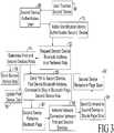
- the user 14touches 66 the second device 22 2 .
- the active identification device communication manager 38communicates with the second device communication controller 26 2 via body coupled communications.
- the second device 22 2authenticates 68 the active identification device 28 and the user to avoid usage by unauthorized users.
- the active identification device 28authenticates 70 the second device 22 2 .
- the active identification device communication manager 38requests 72 the second device communication controller 26 2 to transmit a second device Bluetooth Address and Preferred Bluetooth Role such as master, slave or both.
- the active identification device communication controller 38determines 74 which of the first and second devices 22 1 , 22 2 is the master of the network 40 , e.g.
- the network rolesare assigned to the first and second devices.
- the data of the second device 22 2including at least its role as a master or a slave, is stored 76 in the active identification device memory 60 for a fixed period of Bluetooth data timeout time T out .
- the device role, e.g. master or slave, of the first device 22 1is updated 78 in the active identification device memory 60 if required. It is important to keep the data of the master of the connection - at least this data needs to be stored in the active identification device memory 60 .
- the active identification device communication manager 38sends 80 to the second device communication controller 26 2 a command message to perform a Bluetooth page to the first device 22 1 . More specifically, the active identification device 28 sends 80 the second device communication controller 26 2 a message including the first device Bluetooth address, pin number PIN, a Bluetooth page duration time T pg and the second device network role such as a master or a slave.
- the second device wireless interface 30 2performs 82 the Bluetooth page while the first device wireless interface 30 1 is in the page scan mode, i.e. the Bluetooth interface connection set up between the first and second devices 22 1 , 22 2 is activated 84 . This results in a network connection establishment between the first and second devices for a first-second devices connection establishment duration time T D1-D2 .
- the active identification device communication controller 38sends 90 to the second device 22 2 a request to stay in the page scan mode after the connection between the first and second devices 22 1 , 22 2 has been established.
- the second device 22 2remains 92 in the page scan mode for a time equal to the difference between the Bluetooth data timeout T out and the first-second devices connection establishment duration time T D1-D2 .
- the user 14can touch the first and second peer devices 22 1 , 22 2 at the same time to initiate interconnection of the first and second devices 22 1 , 22 2 into the network 40 .
- the Bluetooth data timeout time T out of the active identification device 28times out, the data of the first and second devices 22 1 , 22 2 is deleted. The connection of the two devices remains unless terminated by other actions or control software on the devices.
- the user 14touches the third device.
- the following situationsare distinguished:
- the systemtakes into account whether the touched network member is the master or one of the slaves and whether the network supports scatternets or not.
- the Bluetooth page time T pg and page scan time T pg_scanare the timeouts for the devices performing Bluetooth Page or Bluetooth Page Scan, respectively.
- the Bluetooth page time T pg and page scan time T pg-scancan be different due to some delays on the body coupled communication.
- the active identification device 28is aware of the introduced delay, e.g. using an internal clock, and modifies accordingly the Bluetooth page time T pg and page scan time T pg_scan in the command message sent to the devices. If the active identification device 28 determines that there is no delay, the active identification device 28 sets the Bluetooth page time T pg to be equal to the page scan time T pg_scan .
- the active identification device 28sets the values of the Bluetooth page time T pg and page scan time T pg_scan according to the application. For example, a value of the Bluetooth data timeout T out is selected to be from about 10 seconds to about 60 seconds. In one embodiment, the value of the Bluetooth data timeout T out is greater than or equal to the Bluetooth page time T pg . In one embodiment, the equal value such as 10 seconds for the Bluetooth data timeout T out , the Bluetooth page time T pg and page scan time T pg_scan is selected. E.g., it is assumed it takes about 10 seconds to touch two devices sequentially.
- Bluetooth discoverydirectly, the user might discover the available devices. The user then selects from a list of all found devices. In this case all devices being in Bluetooth range would be discovered. (This is not really a user friendly solution.)
- the active identification unitis used as a middleman for storage and transmission of necessary information to set up a network connection.
- the BCC interfaceneeds less power as compared to the Bluetooth interface
- using BCC interface for connection set upsaves power compared to using mechanisms of Bluetooth directly as the Bluetooth interface can sleep until needed.
- the method and apparatus described abovecan be applied in all domains where wireless ad hoc networks are being deployed and to all types of wireless technologies such as Bluetooth, WLAN (IEEE 802.11), ZigBee (IEEE 802.15.4) and the like.
- the application areasinclude: (a) Easy and secure set-up of wireless networks for Personal Area Networks as in PHC, including user-specific configuration of devices; (b) Association of body-worn devices with peripheral devices, for example ECG sensor and bedside monitor for home monitoring of vital signs, integration of wireless scale to body area network for personal healthcare applications; and (e) Application in consumer-related application, allowing easy integration of home monitoring functionality into in-home networks.
- some devicescan be on more than one local network. In this manner, two patients in the same household can communicate their medical information to a central location with the same communication device.
Landscapes
- Engineering & Computer Science (AREA)
- Health & Medical Sciences (AREA)
- Biomedical Technology (AREA)
- Medical Informatics (AREA)
- Public Health (AREA)
- General Business, Economics & Management (AREA)
- Life Sciences & Earth Sciences (AREA)
- Computer Networks & Wireless Communication (AREA)
- Business, Economics & Management (AREA)
- General Health & Medical Sciences (AREA)
- Epidemiology (AREA)
- Primary Health Care (AREA)
- Signal Processing (AREA)
- Computer Security & Cryptography (AREA)
- Physics & Mathematics (AREA)
- Biophysics (AREA)
- Pathology (AREA)
- Heart & Thoracic Surgery (AREA)
- Molecular Biology (AREA)
- Surgery (AREA)
- Animal Behavior & Ethology (AREA)
- Veterinary Medicine (AREA)
- Mobile Radio Communication Systems (AREA)
Description
- The following relates to the network systems and methods. It finds particular application in conjunction with short-range medical wireless network systems and will be described with particular reference thereto. However, it is to be appreciated that the following will also find application in conjunction with other network systems and the like.
- Short-range wireless systems typically have a range of less than one hundred meters, but may connect to the Internet to provide communication over longer distances. Short-range wireless systems include, but are not limited to, a wireless personal area network (PAN) and a wireless local area network (LAN). A wireless PAN uses low-cost, low-power wireless devices that have a typical range of about ten meters. An example of a wireless PAN technology is the IEEE 802.15.1 Bluetooth Standard. An example of a wireless LAN technology is the IEEE 802.11x Wireless LAN Standards.
- Typical short-range network devices include, but are not limited to, mobile telephones, personal or laptop computers, and personal electronic devices such as personal digital assistants (PDA), pagers, portable-computing devices, or medical devices. Each Bluetooth device includes application and operating system programs including service discovery protocols which are designed to discover other Bluetooth devices (i.e. peer devices) as they enter or leave the communication range of the Bluetooth device. Devices can dynamically join or leave a Bluetooth network.
- Personal Healthcare systems are increasingly using wireless communication. Typically, wireless medical sensors and devices are used to obtain, process or display telemetric data of the patient such as patient's weight, blood pressure, vital functions, and the like. The wireless medical sensors and devices use radio links for communication and transmission of data to other devices within the network or external care providers. For example, the monitoring systems typically include several devices (such as sensors, measurement devices, displays, servers, communication devices which connect to external medical services) which have to communicate with each other to provide the desired service.
- Setting up such a wireless system is a difficult task. Manual configuration is time-consuming and requires complex interactions and detailed knowledge of communication systems and networking. The user, for example, has to configure network type, network name, network addresses and security parameters (e.g. PINs) for all involved devices. While professionals are typically available to set up and maintain commercial networks in hospitals and health care facilities, this support is not necessarily available for home networks. When it is available, the costs are high. Manual configuration and set up are often not feasible by the patients, as many patients are elderly people who are not technologically literate.
- In addition, when a non-expert user controls the network set up and configuration, an unauthorized user might connect to the devices and make possible the misuse of the system.
- In
EP 1 024 626 A1 - In
EP 1 220 501 A2 - Other solutions use semi-automatic configuration and setup of the wireless communication system. The semi-automatic solutions require additional dedicated setup devices, similar to the manual setup solution, and are complex to use. The present application provides new and improved apparatuses and methods which overcome the above-referenced problems and others.
- In accordance with one aspect, a system for automatic configuration and set up of an ad hoc wireless medical network as set forth in
claim 1 is disclosed. Wireless peer devices each includes a peer body coupled (BCC) interface module for authenticating a patient and transmitting the device identification of a selected peer device via the patient body, and a short-range network interface module for setting up a communication connection between the peer devices. An active identification device, which is linked to the patient, configured to authenticate each selected peer device and automatically associates each selected peer device with the patient. A patient body coupled communication (BCC) interface module is coupled with the patient for transmitting network parameters from the active identification device to the peer devices, configured to communicate patient identification from the active identification device via a patient body to the peer body coupled communication interface module of each selected peer device and to receive the device identification from each selected peer body coupled communication interface module via the patient body when the patient body coupled communication interface is temporarily coupled to the selected peer body coupled communication interface module. - In accordance with another aspect, an adapter for wirelessly interconnecting peer devices, which each includes a short-range wireless interface unit, as set forth in claim 7 is disclosed. A first portion is coupled to a person and includes a person BCC interface for transmitting person identification and network configuration parameters via a person body. A second portion is associated with each individual peer device and respective short-range wireless interface unit, and includes a peer BCC interface for transmitting device identification via the person body when the person and a selected peer device are temporarily coupled and a communication controller which is configured to transmit the device identification of the selected peer device to the first portion via a respective peer body coupled communication interface.
- In accordance with another aspect, a method as set forth in claim 9 is disclosed. A BCC interface, connected to a patient, is temporarily linked to BCC interface modules connected to first and second peer devices. The first and second peer devices are automatically connected into a wireless network in response to the first and second peer devices being linked to the patient BCC interface, wherein the step of automatically connecting includes receiving patient identification via a patient body at the first device; receiving device identification of the first peer device via the patient body at the patient body coupled communication interface; and associating the first peer device identification with the patient identification.
- In accordance with other aspects a wireless peer device as claimed in claim 6 and an active identification device as claimed in
claim 12 are disclosed. - Still further advantages and benefits of the present application will become apparent to those of ordinary skill in the art upon reading and understanding the following detailed description of the preferred embodiments.
- The application may take form in various components and arrangements of components, and in various steps and arrangements of steps. The drawings are only for purposes of illustrating the preferred embodiments and are not to be construed as limiting the application.
FIGURE 1 is a diagrammatic illustration of an identification system;FIGURE 2 shows a process flow of the identification system;FIGURE 3 shows a process flow of the second identification system.- With reference to
FIGURE 1 , amedical system 10 includes anetwork adapter 12 which associates various devices with a user orpatient 14 and configures the associated devices into a network. Thenetwork adapter 12 includes a first portion16 which is linked to thepatient 14 and asecond portion 18 which is included with each of first, second, ..., nth peer devices221, 222, ..., 22n, such as wireless medical devices, communication devices, and the like. - The examples of the peer devices include a
sensor node 221 disposed on the patient14 to monitor vital signs such as electrocardiographic (ECG) data, heart rate, respiratory rate, respiratory cycle, blood pressure, or so forth; and a communication device, such as an illustratedhome television set 222, a remote control, a VCR, a cable box, a computer, and the like. The illustrated devices are examples, and those skilled in the art can readily include additional or other devices such as high resolution sensors, bedside monitors, ventilators, and the like that can be coupled into the network. Moreover, the devices can be arranged into the network on an ad hoc basis by adding or removing medical or communication devices. - Each
second portion 18 includes a first or peer body coupled communication (BCC) interface device or module or unit241, 242, ... , 24n capable of wireless communication via near-feld body-communication technology, which is based on capacitive coupling to thepatient 14, acommunication controller module 28, as described below, and controlling a wireless short-range communication interface device or module orunit Bluetooth interface device - The active identification device or means or
module 28 is attached to or associated with the patient or user or patient'sbody 14 as a band at a wrist, leg, built into a watch, an ID card, or the like. Alternatively, theactive identification device 28 is a noncontact device and is disposed in a close proximity, e.g. within 10cm, of the patient'sbody 14. Theactive identification device 28 utilizes a near-field body-communication technology to communicate with thepeer devices patient 14 is coupled to a selected peer device. Theactive identification device 28 includes a body coupled second or patient or user communication (BCC)interface 36 and acommunication manager 38. As described in detail below, when theuser 14 touches, for example, at least one of the first andsecond devices communication controllers device device communication manager 38 communicate with each other via the peer BCC interface devices241, 242 and patientBCC interface device 36. After verifying the user's authorization, the first andsecond devices active identification device 28, after which the network configuration parameters are received by the touched first andsecond peer devices active identification device 28. Thecommunication controllers communication interface modules second peer device hoc network 40. After thenetwork 40 is established, the application data is exchanged among the first andsecond peer devices wireless network 40 when theuser 14 touches thenth device (not shown) and any device belonging to the establishednetwork 40 such as the first andsecond peer devices - With continuing reference to
FIGURE 1 and further reference toFIGURE 2 , theuser 14 touches46 thefirst device 221. The active identificationdevice communication manager 38 communicates with the firstdevice communication controller 261 via body coupled communications. Thefirst device 221 authenticates48 theactive identification device 28 and the user, e.g. thefirst device 221 reads the patient's identification to avoid usage by unauthorized users. Theactive identification device 28 authenticates50 thefirst device 221 via body coupled communications. After successful mutual authentication, the active identificationdevice communication manager 38 requests52 thefirst device 221 to transmit a first device Bluetooth Address and Preferred Bluetooth Role such as master, slave or both. The first device data is stored54 in an activeidentification device memory 60 for a fixed period of Bluetooth data timeout timeTout. The active identificationdevice communication controller 38 sends62 to the first device communication controller261 a pin number (PIN) to be used during the network connection establishment, a command message to activate the first peerdevice Bluetooth interface 281, and a command for thefirst device 221 to remain64 in a page scan mode for a page scan duration timeTpg_scan. - With continuing reference to
FIGURE 1 and further reference toFIGURE 3 , to connect thesecond device 222 into thenetwork 40, theuser 14 touches66 thesecond device 222. The active identificationdevice communication manager 38 communicates with the seconddevice communication controller 262 via body coupled communications. Thesecond device 222 authenticates68 theactive identification device 28 and the user to avoid usage by unauthorized users. Theactive identification device 28 authenticates70 thesecond device 222. After successful mutual authentication, the active identificationdevice communication manager 38requests 72 the seconddevice communication controller 262 to transmit a second device Bluetooth Address and Preferred Bluetooth Role such as master, slave or both. The active identificationdevice communication controller 38 determines74 which of the first andsecond devices network 40, e.g. the network roles are assigned to the first and second devices. The data of thesecond device 222, including at least its role as a master or a slave, is stored76 in the activeidentification device memory 60 for a fixed period of Bluetooth data timeout timeTout. The device role, e.g. master or slave, of thefirst device 221 is updated78 in the activeidentification device memory 60 if required. It is important to keep the data of the master of the connection - at least this data needs to be stored in the activeidentification device memory 60. - The active identification
device communication manager 38 sends80 to the second device communication controller262 a command message to perform a Bluetooth page to thefirst device 221. More specifically, theactive identification device 28 sends80 the second device communication controller262 a message including the first device Bluetooth address, pin number PIN, a Bluetooth page duration timeTpg and the second device network role such as a master or a slave. The seconddevice wireless interface 302 performs82 the Bluetooth page while the firstdevice wireless interface 301 is in the page scan mode, i.e. the Bluetooth interface connection set up between the first andsecond devices - The active identification
device communication controller 38 sends90 to the second device222 a request to stay in the page scan mode after the connection between the first andsecond devices second device 222 remains92 in the page scan mode for a time equal to the difference between the Bluetooth data timeoutTout and the first-second devices connection establishment duration timeTD1-D2. - Of course, it is also contemplated that the
user 14 can touch the first andsecond peer devices second devices network 40. - If the Bluetooth data timeout timeTout of the
active identification device 28 times out, the data of the first andsecond devices - To connect the third device (not shown) into the established
network 40 between the first andsecond devices user 14 touches the third device. The following situations are distinguished: - (a) The
second device 222 is in the page scan mode: The user touches the third device. The connection is established similar to the establishment of the second device connection described above. - (b) The
second device 222 is in the page scan mode: The connection can be established by the user touching the network member, and subsequently the third device. - (c) The
second device 222 page scan duration timeTpg_scan is expired: The connection can be established by the user touching the third device, and subsequently thenetwork member - (d) The second device page scan duration timeTpg_scan is expired: The connection can be established by the user touching the
network member - The system takes into account whether the touched network member is the master or one of the slaves and whether the network supports scatternets or not.
- The Bluetooth page timeTpg and page scan timeTpg_scan are the timeouts for the devices performing Bluetooth Page or Bluetooth Page Scan, respectively. During the procedure to connect two devices that are not connected to any network, the Bluetooth page timeTpg and page scan timeTpg-scan can be different due to some delays on the body coupled communication. The
active identification device 28 is aware of the introduced delay, e.g. using an internal clock, and modifies accordingly the Bluetooth page time Tpg and page scan timeTpg_scan in the command message sent to the devices. If theactive identification device 28 determines that there is no delay, theactive identification device 28 sets the Bluetooth page timeTpg to be equal to the page scan timeTpg_scan. Theactive identification device 28 sets the values of the Bluetooth page timeTpg and page scan timeTpg_scan according to the application. For example, a value of the Bluetooth data timeoutTout is selected to be from about10 seconds to about 60 seconds. In one embodiment, the value of the Bluetooth data timeoutTout is greater than or equal to the Bluetooth page timeTpg. In one embodiment, the equal value such as 10 seconds for the Bluetooth data timeoutTout, the Bluetooth page timeTpg and page scan time Tpg_scan is selected. E.g., it is assumed it takes about 10 seconds to touch two devices sequentially. - In this manner, intuitive automatic and secure configuration and set-up of wireless networks is accomplished where devices are connected when the user touches the devices simultaneously or subsequently. By mutual authentication between each of the
devices active identification device 28 worn by theuser 14, who is touching the devices to be connected, the connection set-up is limited to authorized persons only. The identified user can connect only to the devices particularly designated for use by the identified user when he/she touches the devices. - As another example, using Bluetooth discovery directly, the user might discover the available devices. The user then selects from a list of all found devices. In this case all devices being in Bluetooth range would be discovered. (This is not really a user friendly solution.)
- In the manner described above, the active identification unit is used as a middleman for storage and transmission of necessary information to set up a network connection. As the BCC interface needs less power as compared to the Bluetooth interface, using BCC interface for connection set up saves power compared to using mechanisms of Bluetooth directly as the Bluetooth interface can sleep until needed.
- The method and apparatus described above can be applied in all domains where wireless ad hoc networks are being deployed and to all types of wireless technologies such as Bluetooth, WLAN (IEEE 802.11), ZigBee (IEEE 802.15.4) and the like. The application areas include: (a) Easy and secure set-up of wireless networks for Personal Area Networks as in PHC, including user-specific configuration of devices; (b) Association of body-worn devices with peripheral devices, for example ECG sensor and bedside monitor for home monitoring of vital signs, integration of wireless scale to body area network for personal healthcare applications; and (e) Application in consumer-related application, allowing easy integration of home monitoring functionality into in-home networks.
- It is also contemplated that some devices, particularly communication devices, can be on more than one local network. In this manner, two patients in the same household can communicate their medical information to a central location with the same communication device.
- The above has been described with reference to the preferred embodiments. Modifications and alterations may occur to others upon a reading and understanding of the preceding detailed description.
Claims (12)
- A system (10) for automatic configuration and set up of an ad hoc wireless medical network (40) comprising:wireless peer devices (221, 222, ... , 22n) which each includes:a peer body coupled communication interface module (241, 242,..., 24n) for authenticating a patient and transmitting device identification of a selected peer device (221, 222, ... , 22n) via the patient body, anda short-range network interface module (301, 302, ..., 30n) for setting up a communication connection between the peer devices (221, 222, ..., 22n); andan active identification device (28), linked to the patient (14), which active identification device (28) is configured to authenticate each selected peer device (221, 222, ..., 22n) and automatically associate each selected peer device (221, 222,..., 22n) with the patient (14), the active identification device including:a patient body coupled communication interface module (36), coupled with the patient (14) for transmitting network parameters from the active identification device (28) to the peer devices (221, 222, ..., 22n), configured to communicate patient identification from the active identification device (28) via a patient body to the peer body coupled communication interface module (241, 242,..., 24n) of each selected peer device (221, 222, ..., 22n) and to receive the device identification from each selected peer body coupled communication interface module (241, 242,..., 24n) via the patient body when the patient body coupled communication interface (36) is temporarily coupled to the selected peer body coupled communication interface module (241, 242,..., 24n).
- The system as set forth in claim 1, wherein the active identification device (28) further includes:a communication manager (38) which is configured to automatically associate the transmitted device identification with the patient identification and assign network configuration parameters to each selected peer device to configure the selected peer devices (221, 222, ... , 22n) into the network (40).
- The system as set forth in claim 2, wherein each peer device (221, 222, ..., 22n) further includes:a communication controller (261, 262, ..., 26n) which is configured to transmit the device identification to the communication manager (38) and receive the network configuration parameters from the communication manager (38), the communication controller (261, 262, ... , 26n) and communication manager (38) configured to communicate with one another via the selected peer body coupled communication interface module and patient body coupled communication interface module.
- The system as set forth in claim 3, wherein the communication manager (38) is configured to configure the short-range network interface modules (301, 302, ..., 30n) of the selected peer devices (221, 222, ..., 22n) to establish network connection between the selected peer devices (221, 222, ... , 22n).
- The system as set forth in claim 2, wherein the active identification device (28) further includes:a memory (60) which is configured to store the transmitted device identification and assigned network parameters of the selected peer devices for a data timeout time (Tout).
- A wireless peer device (221, 222, ..., 22n) for use in the system of claim 1, the wireless peer device including:said peer body coupled communication interface module (241, 242,..., 24n) and said short range network interface module (301, 302, ..., 30n); anda communication controller (261, 262, ..., 26n) which is configured to transmit the device identification to a communication manager (38) comprised in the active identification device and receive the network configuration parameters from the communication manager (38), the communication controller (261, 262, ... , 26n) and communication manager (38) are configured to bidirectionally communicate with one another via a patient body.
- An adapter (12) for wirelessly interconnecting peer devices (221, 222, ..., 22n), which each includes a short-range wireless interface unit (301, 302, ..., 30n), the adapter (12) comprising:a first portion (16) coupled to a person (14) and including a person body coupled communication interface (36) for transmitting person identification and network configuration parameters via a person body; anda second portion (18) associated with each individual peer device (221, 222, ..., 22n) and respective short-range wireless interface unit (301, 302, ..., 30n), which second portion (18) includes a peer body coupled communication interface (241, 242,..., 24n) for transmitting device identification via the person body when the person (14) and a selected peer device (221, 222, ..., , 22n) are temporarily coupled and a communication controller (261, 262, ..., 26n) which is configured to transmit the device identification of the selected peer device (221, 222, ..., 22n) to the first portion (16) via a respective peer body coupled communication interface (241, 242, ..., 24n).
- The adapter as set forth in claim 7, wherein the first portion (16) further includes:a communication manager (38) which is configured to automatically associate the transmitted device identification with the person identification and transmit the network configuration parameters to a communication controller (261, 262, ... , 26n) of the selected peer device (221, 222, ... , 22n) to interconnect the short-range wireless interface unit (301, 302, ..., 30n) of each selected peer device (221, 222, ..., 22n) so that the selected peer devices (221, 222, ..., , 22n) form the network (40).
- A method comprising:temporarily linking a body coupled communication interface, connected to a patient, to body coupled communication interface modules connected to first and second peer devices; andautomatically connecting the first and second peer devices into a wireless network in response to the first and second peer devices being linked to the patient body coupled communication interface, wherein the step of automatically connecting includes receiving patient identification via a patient body at the first peer device;receiving device identification of the first peer device via the patient body at the patient body coupled communication interface; andassociating the first peer device identification with the patient identification.
- The method as set forth in claim 9, further including:receiving patient identification via the patient body at the second peer device;receiving device identification of the second peer device via the patient body at the patient body coupled communication interface;associating the second peer device with the patient identification;transmitting network configuration parameters to the second peer device; andactivating a second short-range network interface module on the second peer device.
- The method as set forth in claim 10, wherein the step of linking includes one of:contemporaneously linking the patient body coupled communication interface to the body coupled communication interface modules connected to the first and second peer devices, andlinking the patient body coupled communication interface to the body coupled communication interface module connected to the second peer device subsequent to linking the patient body coupled communication interface to the body coupled communication interface module connected to the first peer device.
- An active identification device (28) for automatically connecting first and second peer devices into a wireless network, said active identification device (28) being configured to
temporarily link a body coupled communication interface, connected to a patient, to body coupled communication interface modules connected to the first and second peer devices; and
automatically connect the first and second peer devices into a wireless network in response to the first and second peer devices being linked to the patient body coupled communication interface;
communicate patient identification via a patient body to the first peer device;
receive device identification of the first peer device via the patient body at the patient body coupled communication interface; and
associate the first peer device identification with the patient identification.
Applications Claiming Priority (2)
| Application Number | Priority Date | Filing Date | Title |
|---|---|---|---|
| US76002006P | 2006-01-18 | 2006-01-18 | |
| PCT/US2007/060204WO2007084807A1 (en) | 2006-01-18 | 2007-01-08 | Automatic and secure configuration of wireless medical networks |
Publications (2)
| Publication Number | Publication Date |
|---|---|
| EP1980065A1 EP1980065A1 (en) | 2008-10-15 |
| EP1980065B1true EP1980065B1 (en) | 2017-05-24 |
Family
ID=38110289
Family Applications (1)
| Application Number | Title | Priority Date | Filing Date |
|---|---|---|---|
| EP07709981.0ANot-in-forceEP1980065B1 (en) | 2006-01-18 | 2007-01-08 | Automatic and secure configuration of wireless medical networks |
Country Status (4)
| Country | Link |
|---|---|
| US (1) | US20090070472A1 (en) |
| EP (1) | EP1980065B1 (en) |
| CN (1) | CN101371530B (en) |
| WO (1) | WO2007084807A1 (en) |
Families Citing this family (29)
| Publication number | Priority date | Publication date | Assignee | Title |
|---|---|---|---|---|
| CN101606159A (en)* | 2007-02-15 | 2009-12-16 | 皇家飞利浦电子股份有限公司 | Resident annotations for wireless sensors |
| KR101540475B1 (en)* | 2007-11-30 | 2015-07-29 | 삼성전자주식회사 | Method and system for sharing data in a local area network |
| US8332495B2 (en)* | 2008-06-27 | 2012-12-11 | Affinegy, Inc. | System and method for securing a wireless network |
| CN102132281B (en) | 2008-08-28 | 2016-02-03 | 皇家飞利浦电子股份有限公司 | Sensor for wearing for patient provides the method and system of patient's identification beacon |
| US9585562B2 (en)* | 2008-12-03 | 2017-03-07 | Carefusion 303, Inc. | Method and apparatus for automatically integrating a medical device into a medical facility network |
| ES2388488T3 (en) | 2008-12-23 | 2012-10-15 | Koninklijke Philips Electronics N.V. | Combination of body coupled communication and radio frequency communication |
| US20110028091A1 (en)* | 2009-08-03 | 2011-02-03 | Motorola, Inc. | Method and system for near-field wireless device pairing |
| US8850196B2 (en)* | 2010-03-29 | 2014-09-30 | Motorola Solutions, Inc. | Methods for authentication using near-field |
| US8744803B2 (en) | 2010-09-30 | 2014-06-03 | Fitbit, Inc. | Methods, systems and devices for activity tracking device data synchronization with computing devices |
| US9253168B2 (en)* | 2012-04-26 | 2016-02-02 | Fitbit, Inc. | Secure pairing of devices via pairing facilitator-intermediary device |
| JP5923519B2 (en) | 2010-12-22 | 2016-05-24 | コーニンクレッカ フィリップス エヌ ヴェKoninklijke Philips N.V. | System and method for providing medical care provider and device management for patient care |
| US8776246B2 (en)* | 2011-03-11 | 2014-07-08 | Abbott Point Of Care, Inc. | Systems, methods and analyzers for establishing a secure wireless network in point of care testing |
| CN103379580B (en)* | 2012-04-13 | 2018-12-14 | 华为技术有限公司 | The method, apparatus and system of equipment discovery |
| US8935411B2 (en)* | 2012-08-22 | 2015-01-13 | Nokia Corporation | Method and apparatus for utilizing advertisements to provide information regarding connection setup |
| US8806205B2 (en) | 2012-12-27 | 2014-08-12 | Motorola Solutions, Inc. | Apparatus for and method of multi-factor authentication among collaborating communication devices |
| US9332431B2 (en) | 2012-12-27 | 2016-05-03 | Motorola Solutions, Inc. | Method of and system for authenticating and operating personal communication devices over public safety networks |
| US8782766B1 (en) | 2012-12-27 | 2014-07-15 | Motorola Solutions, Inc. | Method and apparatus for single sign-on collaboration among mobile devices |
| US8955081B2 (en) | 2012-12-27 | 2015-02-10 | Motorola Solutions, Inc. | Method and apparatus for single sign-on collaboraton among mobile devices |
| EP2811770A1 (en)* | 2013-06-07 | 2014-12-10 | Gemalto SA | Pairing device |
| EP3014516A1 (en)* | 2013-06-28 | 2016-05-04 | Koninklijke Philips N.V. | System for managing access to medical data |
| WO2015180937A1 (en) | 2014-05-27 | 2015-12-03 | Koninklijke Philips N.V. | Body coupled communication device with synchronization |
| CN106716881A (en) | 2014-09-23 | 2017-05-24 | 皇家飞利浦有限公司 | Dynamic configuration of body coupled communication devices |
| CN107113067B (en)* | 2014-11-27 | 2021-02-09 | 索尼公司 | Communication apparatus, communication method, and communication system |
| CN105704837B (en)* | 2014-11-28 | 2020-02-14 | 华为终端有限公司 | Method and equipment for establishing wireless connection |
| CN104510478B (en)* | 2014-12-08 | 2017-01-25 | 华南理工大学 | Wearable device based blood oxygen saturation degree detection device |
| US20160212194A1 (en)* | 2015-01-16 | 2016-07-21 | Nokia Technologies Oy | Method, apparatus, and computer program product for device control |
| US9712256B2 (en)* | 2015-02-03 | 2017-07-18 | Sony Corporation | Method and system for capturing media by using BAN |
| US10582981B2 (en) | 2016-02-02 | 2020-03-10 | Stryker Corporation | Accessory support and coupling systems for an accessory support |
| US11271662B2 (en)* | 2019-06-11 | 2022-03-08 | Qualcomm Incorporated | Low power communication links between wireless devices |
Family Cites Families (14)
| Publication number | Priority date | Publication date | Assignee | Title |
|---|---|---|---|---|
| US6968375B1 (en)* | 1997-03-28 | 2005-11-22 | Health Hero Network, Inc. | Networked system for interactive communication and remote monitoring of individuals |
| EP0824799B1 (en)* | 1995-05-08 | 2002-08-21 | Massachusetts Institute Of Technology | System for non-contact sensing and signalling using human body as signal transmission medium |
| US6211799B1 (en)* | 1997-11-06 | 2001-04-03 | Massachusetts Institute Of Technology | Method and apparatus for transbody transmission of power and information |
| EP1024626A1 (en)* | 1999-01-27 | 2000-08-02 | International Business Machines Corporation | Method, apparatus, and communication system for exchange of information in pervasive environments |
| JP2001195368A (en)* | 1999-11-01 | 2001-07-19 | Sony Corp | Authentication information communication system, authentication information communication method, portable information processor and program provision medium |
| FI110560B (en)* | 2000-12-27 | 2003-02-14 | Nokia Corp | Group setup for wireless communication terminals |
| US7051120B2 (en)* | 2001-12-28 | 2006-05-23 | International Business Machines Corporation | Healthcare personal area identification network method and system |
| JP3885597B2 (en)* | 2002-02-05 | 2007-02-21 | ソニー株式会社 | Wireless communication system, wireless communication control method, wireless communication apparatus, wireless communication method, and computer program |
| AU2002343514A1 (en)* | 2002-10-15 | 2004-05-04 | Otis Elevator Company | Elevator wireless communication infrastructure using piconet modules |
| WO2004064340A1 (en)* | 2003-01-10 | 2004-07-29 | Philips Intellectual Property & Standards Gmbh | Network and terminal for forming an adhoc network by responsive to an inquiry forwarded by a slave terminal, setting up by the master unit a connection with the terminal to be incorporated into the network |
| KR100490429B1 (en)* | 2003-04-25 | 2005-05-17 | 삼성전자주식회사 | System and method for managing the association of device to a piconet |
| US7895053B2 (en)* | 2003-10-07 | 2011-02-22 | Hospira, Inc. | Medication management system |
| US20050086071A1 (en)* | 2003-10-15 | 2005-04-21 | Fox Charles S.Jr. | System and method for managing patient care |
| JP4865733B2 (en)* | 2005-02-17 | 2012-02-01 | コーニンクレッカ フィリップス エレクトロニクス エヌ ヴィ | Device capable of being operated in a network, network system, method for operating a device in a network, program element and computer-readable medium |
- 2007
- 2007-01-08EPEP07709981.0Apatent/EP1980065B1/ennot_activeNot-in-force
- 2007-01-08USUS12/160,892patent/US20090070472A1/ennot_activeAbandoned
- 2007-01-08CNCN200780002571.7Apatent/CN101371530B/ennot_activeExpired - Fee Related
- 2007-01-08WOPCT/US2007/060204patent/WO2007084807A1/enactiveApplication Filing
Also Published As
| Publication number | Publication date |
|---|---|
| CN101371530B (en) | 2017-08-29 |
| CN101371530A (en) | 2009-02-18 |
| EP1980065A1 (en) | 2008-10-15 |
| US20090070472A1 (en) | 2009-03-12 |
| WO2007084807A1 (en) | 2007-07-26 |
Similar Documents
| Publication | Publication Date | Title |
|---|---|---|
| EP1980065B1 (en) | Automatic and secure configuration of wireless medical networks | |
| Baldus et al. | Reliable set-up of medical body-sensor networks | |
| CN104584677B (en) | The communicator independent of treater of network availability and method | |
| US8405502B2 (en) | Identification and connectivity gateway wristband for hospital and medical applications | |
| JP6195344B2 (en) | X-ray imaging system, control method of X-ray imaging system, and program | |
| CN101411113B (en) | Authentication relay device, authentication relay system, integrated circuit and authentication relay method | |
| US20220167155A1 (en) | System for secure passive wireless communication with bluetooth vitals devices | |
| Aragues et al. | Trends and challenges of the emerging technologies toward interoperability and standardization in e-health communications | |
| JP2008522459A (en) | Time synchronization in wireless ad hoc networks of medical devices and sensors | |
| US20190215369A1 (en) | Secure Wireless Communication Platform | |
| US20140020081A1 (en) | Portable Token Device | |
| EP2922314B1 (en) | A method and technical equipment for short range data transmission | |
| TW200410525A (en) | Bluetooth remote access device | |
| CN101120527A (en) | Device capable of operating within a network, network system, method of operating a device within a network, program components, and computer-readable medium | |
| US10484363B2 (en) | Method and apparatus for authenticating a device using Bluetooth technology | |
| Frehill et al. | Using zigbee to integrate medical devices | |
| WO2008085131A1 (en) | A wireless network for personal computer human interface devices | |
| WO2022051289A1 (en) | Automatic pairing of devices to a communication gateway | |
| CN103518409A (en) | Method and device for selecting a channel according to a device's mobility | |
| KR100250477B1 (en) | Location tracking method of mobile terminal using radio lan | |
| JP2006526324A (en) | How to establish a wireless communication connection | |
| JP7324199B2 (en) | Protect headless devices from malicious (re)configuration | |
| KR100655576B1 (en) | How to register Bluetooth ID using Bluetooth access point registration function | |
| JP2001285956A (en) | Wireless communication network system and its wireless station device | |
| EP3989610B1 (en) | Device, system and method for clustering ble devices |
Legal Events
| Date | Code | Title | Description |
|---|---|---|---|
| PUAI | Public reference made under article 153(3) epc to a published international application that has entered the european phase | Free format text:ORIGINAL CODE: 0009012 | |
| 17P | Request for examination filed | Effective date:20080818 | |
| AK | Designated contracting states | Kind code of ref document:A1 Designated state(s):AT BE BG CH CY CZ DE DK EE ES FI FR GB GR HU IE IS IT LI LT LU LV MC NL PL PT RO SE SI SK TR | |
| DAX | Request for extension of the european patent (deleted) | ||
| 17Q | First examination report despatched | Effective date:20130514 | |
| RAP1 | Party data changed (applicant data changed or rights of an application transferred) | Owner name:KONINKLIJKE PHILIPS N.V. | |
| REG | Reference to a national code | Ref country code:DE Ref legal event code:R079 Ref document number:602007051107 Country of ref document:DE Free format text:PREVIOUS MAIN CLASS: H04L0012560000 Ipc:A61B0005000000 | |
| GRAP | Despatch of communication of intention to grant a patent | Free format text:ORIGINAL CODE: EPIDOSNIGR1 | |
| RIC1 | Information provided on ipc code assigned before grant | Ipc:H04W 12/06 20090101ALN20161110BHEP Ipc:G06F 19/00 20110101ALN20161110BHEP Ipc:H04W 84/18 20090101ALN20161110BHEP Ipc:A61B 5/00 20060101AFI20161110BHEP | |
| RIC1 | Information provided on ipc code assigned before grant | Ipc:A61B 5/00 20060101AFI20161114BHEP Ipc:G06F 19/00 20110101ALN20161114BHEP Ipc:H04W 12/06 20090101ALN20161114BHEP Ipc:H04W 84/18 20090101ALN20161114BHEP | |
| INTG | Intention to grant announced | Effective date:20161214 | |
| GRAS | Grant fee paid | Free format text:ORIGINAL CODE: EPIDOSNIGR3 | |
| GRAA | (expected) grant | Free format text:ORIGINAL CODE: 0009210 | |
| AK | Designated contracting states | Kind code of ref document:B1 Designated state(s):AT BE BG CH CY CZ DE DK EE ES FI FR GB GR HU IE IS IT LI LT LU LV MC NL PL PT RO SE SI SK TR | |
| REG | Reference to a national code | Ref country code:GB Ref legal event code:FG4D | |
| REG | Reference to a national code | Ref country code:CH Ref legal event code:EP | |
| REG | Reference to a national code | Ref country code:IE Ref legal event code:FG4D | |
| REG | Reference to a national code | Ref country code:AT Ref legal event code:REF Ref document number:895590 Country of ref document:AT Kind code of ref document:T Effective date:20170615 | |
| REG | Reference to a national code | Ref country code:DE Ref legal event code:R096 Ref document number:602007051107 Country of ref document:DE | |
| REG | Reference to a national code | Ref country code:NL Ref legal event code:MP Effective date:20170524 | |
| REG | Reference to a national code | Ref country code:LT Ref legal event code:MG4D | |
| REG | Reference to a national code | Ref country code:AT Ref legal event code:MK05 Ref document number:895590 Country of ref document:AT Kind code of ref document:T Effective date:20170524 | |
| PG25 | Lapsed in a contracting state [announced via postgrant information from national office to epo] | Ref country code:FI Free format text:LAPSE BECAUSE OF FAILURE TO SUBMIT A TRANSLATION OF THE DESCRIPTION OR TO PAY THE FEE WITHIN THE PRESCRIBED TIME-LIMIT Effective date:20170524 Ref country code:AT Free format text:LAPSE BECAUSE OF FAILURE TO SUBMIT A TRANSLATION OF THE DESCRIPTION OR TO PAY THE FEE WITHIN THE PRESCRIBED TIME-LIMIT Effective date:20170524 Ref country code:LT Free format text:LAPSE BECAUSE OF FAILURE TO SUBMIT A TRANSLATION OF THE DESCRIPTION OR TO PAY THE FEE WITHIN THE PRESCRIBED TIME-LIMIT Effective date:20170524 Ref country code:GR Free format text:LAPSE BECAUSE OF FAILURE TO SUBMIT A TRANSLATION OF THE DESCRIPTION OR TO PAY THE FEE WITHIN THE PRESCRIBED TIME-LIMIT Effective date:20170825 Ref country code:ES Free format text:LAPSE BECAUSE OF FAILURE TO SUBMIT A TRANSLATION OF THE DESCRIPTION OR TO PAY THE FEE WITHIN THE PRESCRIBED TIME-LIMIT Effective date:20170524 | |
| PG25 | Lapsed in a contracting state [announced via postgrant information from national office to epo] | Ref country code:NL Free format text:LAPSE BECAUSE OF FAILURE TO SUBMIT A TRANSLATION OF THE DESCRIPTION OR TO PAY THE FEE WITHIN THE PRESCRIBED TIME-LIMIT Effective date:20170524 Ref country code:BG Free format text:LAPSE BECAUSE OF FAILURE TO SUBMIT A TRANSLATION OF THE DESCRIPTION OR TO PAY THE FEE WITHIN THE PRESCRIBED TIME-LIMIT Effective date:20170824 Ref country code:SE Free format text:LAPSE BECAUSE OF FAILURE TO SUBMIT A TRANSLATION OF THE DESCRIPTION OR TO PAY THE FEE WITHIN THE PRESCRIBED TIME-LIMIT Effective date:20170524 Ref country code:IS Free format text:LAPSE BECAUSE OF FAILURE TO SUBMIT A TRANSLATION OF THE DESCRIPTION OR TO PAY THE FEE WITHIN THE PRESCRIBED TIME-LIMIT Effective date:20170924 Ref country code:LV Free format text:LAPSE BECAUSE OF FAILURE TO SUBMIT A TRANSLATION OF THE DESCRIPTION OR TO PAY THE FEE WITHIN THE PRESCRIBED TIME-LIMIT Effective date:20170524 | |
| REG | Reference to a national code | Ref country code:FR Ref legal event code:PLFP Year of fee payment:12 | |
| PG25 | Lapsed in a contracting state [announced via postgrant information from national office to epo] | Ref country code:EE Free format text:LAPSE BECAUSE OF FAILURE TO SUBMIT A TRANSLATION OF THE DESCRIPTION OR TO PAY THE FEE WITHIN THE PRESCRIBED TIME-LIMIT Effective date:20170524 Ref country code:RO Free format text:LAPSE BECAUSE OF FAILURE TO SUBMIT A TRANSLATION OF THE DESCRIPTION OR TO PAY THE FEE WITHIN THE PRESCRIBED TIME-LIMIT Effective date:20170524 Ref country code:DK Free format text:LAPSE BECAUSE OF FAILURE TO SUBMIT A TRANSLATION OF THE DESCRIPTION OR TO PAY THE FEE WITHIN THE PRESCRIBED TIME-LIMIT Effective date:20170524 Ref country code:CZ Free format text:LAPSE BECAUSE OF FAILURE TO SUBMIT A TRANSLATION OF THE DESCRIPTION OR TO PAY THE FEE WITHIN THE PRESCRIBED TIME-LIMIT Effective date:20170524 Ref country code:SK Free format text:LAPSE BECAUSE OF FAILURE TO SUBMIT A TRANSLATION OF THE DESCRIPTION OR TO PAY THE FEE WITHIN THE PRESCRIBED TIME-LIMIT Effective date:20170524 | |
| REG | Reference to a national code | Ref country code:DE Ref legal event code:R097 Ref document number:602007051107 Country of ref document:DE | |
| PG25 | Lapsed in a contracting state [announced via postgrant information from national office to epo] | Ref country code:PL Free format text:LAPSE BECAUSE OF FAILURE TO SUBMIT A TRANSLATION OF THE DESCRIPTION OR TO PAY THE FEE WITHIN THE PRESCRIBED TIME-LIMIT Effective date:20170524 Ref country code:IT Free format text:LAPSE BECAUSE OF FAILURE TO SUBMIT A TRANSLATION OF THE DESCRIPTION OR TO PAY THE FEE WITHIN THE PRESCRIBED TIME-LIMIT Effective date:20170524 | |
| PLBE | No opposition filed within time limit | Free format text:ORIGINAL CODE: 0009261 | |
| STAA | Information on the status of an ep patent application or granted ep patent | Free format text:STATUS: NO OPPOSITION FILED WITHIN TIME LIMIT | |
| 26N | No opposition filed | Effective date:20180227 | |
| PG25 | Lapsed in a contracting state [announced via postgrant information from national office to epo] | Ref country code:SI Free format text:LAPSE BECAUSE OF FAILURE TO SUBMIT A TRANSLATION OF THE DESCRIPTION OR TO PAY THE FEE WITHIN THE PRESCRIBED TIME-LIMIT Effective date:20170524 | |
| REG | Reference to a national code | Ref country code:CH Ref legal event code:PL | |
| PG25 | Lapsed in a contracting state [announced via postgrant information from national office to epo] | Ref country code:LU Free format text:LAPSE BECAUSE OF NON-PAYMENT OF DUE FEES Effective date:20180108 | |
| REG | Reference to a national code | Ref country code:IE Ref legal event code:MM4A | |
| REG | Reference to a national code | Ref country code:BE Ref legal event code:MM Effective date:20180131 | |
| PG25 | Lapsed in a contracting state [announced via postgrant information from national office to epo] | Ref country code:LI Free format text:LAPSE BECAUSE OF NON-PAYMENT OF DUE FEES Effective date:20180131 Ref country code:CH Free format text:LAPSE BECAUSE OF NON-PAYMENT OF DUE FEES Effective date:20180131 Ref country code:BE Free format text:LAPSE BECAUSE OF NON-PAYMENT OF DUE FEES Effective date:20180131 | |
| PG25 | Lapsed in a contracting state [announced via postgrant information from national office to epo] | Ref country code:IE Free format text:LAPSE BECAUSE OF NON-PAYMENT OF DUE FEES Effective date:20180108 | |
| PG25 | Lapsed in a contracting state [announced via postgrant information from national office to epo] | Ref country code:MC Free format text:LAPSE BECAUSE OF FAILURE TO SUBMIT A TRANSLATION OF THE DESCRIPTION OR TO PAY THE FEE WITHIN THE PRESCRIBED TIME-LIMIT Effective date:20170524 | |
| PG25 | Lapsed in a contracting state [announced via postgrant information from national office to epo] | Ref country code:TR Free format text:LAPSE BECAUSE OF FAILURE TO SUBMIT A TRANSLATION OF THE DESCRIPTION OR TO PAY THE FEE WITHIN THE PRESCRIBED TIME-LIMIT Effective date:20170524 | |
| PGFP | Annual fee paid to national office [announced via postgrant information from national office to epo] | Ref country code:GB Payment date:20200129 Year of fee payment:14 | |
| PG25 | Lapsed in a contracting state [announced via postgrant information from national office to epo] | Ref country code:HU Free format text:LAPSE BECAUSE OF FAILURE TO SUBMIT A TRANSLATION OF THE DESCRIPTION OR TO PAY THE FEE WITHIN THE PRESCRIBED TIME-LIMIT; INVALID AB INITIO Effective date:20070108 Ref country code:PT Free format text:LAPSE BECAUSE OF FAILURE TO SUBMIT A TRANSLATION OF THE DESCRIPTION OR TO PAY THE FEE WITHIN THE PRESCRIBED TIME-LIMIT Effective date:20170524 | |
| PG25 | Lapsed in a contracting state [announced via postgrant information from national office to epo] | Ref country code:CY Free format text:LAPSE BECAUSE OF FAILURE TO SUBMIT A TRANSLATION OF THE DESCRIPTION OR TO PAY THE FEE WITHIN THE PRESCRIBED TIME-LIMIT Effective date:20170524 | |
| PGFP | Annual fee paid to national office [announced via postgrant information from national office to epo] | Ref country code:FR Payment date:20200128 Year of fee payment:14 | |
| GBPC | Gb: european patent ceased through non-payment of renewal fee | Effective date:20210108 | |
| PG25 | Lapsed in a contracting state [announced via postgrant information from national office to epo] | Ref country code:FR Free format text:LAPSE BECAUSE OF NON-PAYMENT OF DUE FEES Effective date:20210131 | |
| PG25 | Lapsed in a contracting state [announced via postgrant information from national office to epo] | Ref country code:GB Free format text:LAPSE BECAUSE OF NON-PAYMENT OF DUE FEES Effective date:20210108 | |
| PGFP | Annual fee paid to national office [announced via postgrant information from national office to epo] | Ref country code:DE Payment date:20220127 Year of fee payment:16 | |
| REG | Reference to a national code | Ref country code:DE Ref legal event code:R119 Ref document number:602007051107 Country of ref document:DE | |
| PG25 | Lapsed in a contracting state [announced via postgrant information from national office to epo] | Ref country code:DE Free format text:LAPSE BECAUSE OF NON-PAYMENT OF DUE FEES Effective date:20230801 |