EP1977256B1 - Swing performance analysis device - Google Patents
Swing performance analysis deviceDownload PDFInfo
- Publication number
- EP1977256B1 EP1977256B1EP06794662AEP06794662AEP1977256B1EP 1977256 B1EP1977256 B1EP 1977256B1EP 06794662 AEP06794662 AEP 06794662AEP 06794662 AEP06794662 AEP 06794662AEP 1977256 B1EP1977256 B1EP 1977256B1
- Authority
- EP
- European Patent Office
- Prior art keywords
- swing
- accelerometer
- processor
- analysis device
- performance analysis
- Prior art date
- Legal status (The legal status is an assumption and is not a legal conclusion. Google has not performed a legal analysis and makes no representation as to the accuracy of the status listed.)
- Not-in-force
Links
- 238000004458analytical methodMethods0.000titleclaimsabstractdescription27
- 238000005259measurementMethods0.000claimsabstractdescription30
- 230000001133accelerationEffects0.000claimsabstractdescription18
- 238000001514detection methodMethods0.000claimsdescription3
- 238000000034methodMethods0.000description6
- 238000010586diagramMethods0.000description5
- 238000012937correctionMethods0.000description2
- 238000012544monitoring processMethods0.000description2
- 238000012549trainingMethods0.000description2
- 210000000707wristAnatomy0.000description2
- 241000950638Symphysodon discusSpecies0.000description1
- 230000002411adverseEffects0.000description1
- 230000003321amplificationEffects0.000description1
- 238000010276constructionMethods0.000description1
- 230000001419dependent effectEffects0.000description1
- 238000006073displacement reactionMethods0.000description1
- 230000000694effectsEffects0.000description1
- 238000005516engineering processMethods0.000description1
- 238000001914filtrationMethods0.000description1
- 210000004247handAnatomy0.000description1
- HOQADATXFBOEGG-UHFFFAOYSA-NisofenphosChemical compoundCCOP(=S)(NC(C)C)OC1=CC=CC=C1C(=O)OC(C)CHOQADATXFBOEGG-UHFFFAOYSA-N0.000description1
- 239000004973liquid crystal related substanceSubstances0.000description1
- 238000003199nucleic acid amplification methodMethods0.000description1
Images


Classifications
- A—HUMAN NECESSITIES
- A63—SPORTS; GAMES; AMUSEMENTS
- A63B—APPARATUS FOR PHYSICAL TRAINING, GYMNASTICS, SWIMMING, CLIMBING, OR FENCING; BALL GAMES; TRAINING EQUIPMENT
- A63B69/00—Training appliances or apparatus for special sports
- A63B69/36—Training appliances or apparatus for special sports for golf
- A63B69/3623—Training appliances or apparatus for special sports for golf for driving
- A63B69/3632—Clubs or attachments on clubs, e.g. for measuring, aligning
- A—HUMAN NECESSITIES
- A63—SPORTS; GAMES; AMUSEMENTS
- A63B—APPARATUS FOR PHYSICAL TRAINING, GYMNASTICS, SWIMMING, CLIMBING, OR FENCING; BALL GAMES; TRAINING EQUIPMENT
- A63B2220/00—Measuring of physical parameters relating to sporting activity
- A63B2220/40—Acceleration
- A—HUMAN NECESSITIES
- A63—SPORTS; GAMES; AMUSEMENTS
- A63B—APPARATUS FOR PHYSICAL TRAINING, GYMNASTICS, SWIMMING, CLIMBING, OR FENCING; BALL GAMES; TRAINING EQUIPMENT
- A63B2225/00—Miscellaneous features of sport apparatus, devices or equipment
- A63B2225/50—Wireless data transmission, e.g. by radio transmitters or telemetry
Definitions
- the present inventionrelates to a device for analysing swing performance that is particularly applicable for use in golf training.
- Speed indicatorsare typically either free-standing or attach to, or form part of, the club.
- Free standing indicatorstypically employ a sensor arrangement that uses magnetic forces, light beams or microwave radar to measure club activity and motion. More complex methods use gyroscopes and multi-axis accelerometers or video cameras/recorders connected to a computer for analysis.
- Radar and light/laser devicesare typically expensive, obtrusive, inaccurate, and can be difficult to set up. In the case of the radar devices, the point of measurement is not well defined. As the speed of, and therefore distance travelled by, the ball is dependent on the speed of the club head at impact, measurements at other times are not useful in this respect. Radar and laser devices also only produce speed information, which is, by itself, insufficient. More complex methods produce detailed results, but these require considerable skill and/or expertise to interpret, and so are not useful to the majority of golfers.
- Speed measuring devicesexist, such as that disclosed in US 3,815,427 , which fix to the club typically use one or more accelerometers to derive club head speed indirectly, by combining centripetal acceleration with radius of curvature. However these tend to be inaccurate for a number of reasons.
- Some methodsrequire knowledge of properties of the equipment, such as the weight of the club head, and/or the ball. Furthermore, none of the systems or devices known to the applicant take into account the slowing distance of the club (the distance travelled by the club head between reaching peak speed and the instant of impact with the ball) which clearly affects the accuracy of any measurements provided.
- JP 10127845 Adiscloses a swing performance analysis device according to the preamble of claim 1.
- the devicecomprises a housing securable to the shaft of the golf club, the accelerometer being mounted in the housing such that upon securement of the device to the shaft of the golf club, the axis of measurement of the accelerometer is parallel to the longitudinal axis of the shaft.
- the one or more parametersmay include the length of the user's arm.
- the processoris arranged to monitor measurement data from the accelerometer to determine when a swing is being taken and a point of impact, wherein measurement data corresponding to a swing being taken comprises a low frequency waveform and measurement data corresponding to a point of impact comprises a high frequency burst or sudden reduction in centripetal acceleration.
- a swingmay be deemed to have started, when the output of the accelerometer reaches a predetermined threshold.
- the processormay be arranged to sample measurement data more frequently once a swing is deemed to have started.
- the processoris preferably arranged to determine a peak speed of the swing, the peak speed comprising measurement data received from the accelerometer having a smaller magnitude than its predecessor.
- the devicewould preferably be easy to set up, and would require only one measurement to be input by the user, which should, be easy to determine. It would be easy to clip onto the shaft of most clubs, and would be secure in use.
- the deviceshould ideally work in both imperial and metric units, it should be reliable, and have adequate battery life.
- the inventionovercomes the problems of prior art.
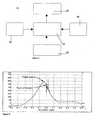
- Figure 1is a schematic diagram of an analysis device according to an embodiment of the present invention.
- the analysis device 10includes a single-axis accelerometer 20, a processor 30, a display 40, and user controls 50.
- Figures 2 and 3are perspective views of the analysis device of Figure 1 ;
- the device 10is self-contained and includes an aperture 11 and securing means 12 enabling the device to be secured to the shaft of a golf club, as is shown in Figure 4 .
- the deviceis secured on the shaft 60 as close as possible to the club head 70.
- the accelerometer 20is orientated such that the measurement axis of the accelerometer is parallel to the axis of the shaft and the direction of the acceleration to be measured is towards the club head.
- the output from the accelerometer 20is preconditioned by analogue circuitry, and the resultant signal is input to the processor 30 in which the signal is converted into the digital domain, and is processed to analyze the swing. Data on the swing is output to the display 40.
- Preconditioningdepends on the technology used in the accelerometer. Some will require temperature compensation, most will need amplification. Low pass filtering may also be desirable to control EMC susceptibility. The important thing is that the signal has sufficient magnitude and stability to properly drive the ADC, and thus achieve suitable measurement accuracy and resolution.
- the user controls 50are preferably push-button switches. One would switch the unit on and off, and reset the display after each stroke. The other would allow the user to scroll through the various results. A combination of presses would allow setting up of the device 10 and any other settings which may be desired.
- the usersets up the device by inputting a parameter corresponding to the length of their arm plus the length of the club. Following a swing, the device displays the peak speed, speed at impact and slowing distance on the display 40. Using this information, the golfer is able to make adjustments to the swing to improve his or her technique by seeking to increase club head speed at impact and reduce slowing distance.
- the accelerometeris oriented to measure centripetal acceleration along the length of the shaft. It produces an electrical output which is processed by a processor 30. During a typical golf swing this output has the form shown in Figure 5 .
- the processor 30monitors the accelerometer output at regular intervals. The swing is deemed to have started when the output of the accelerometer reaches a preset threshold. The monitoring of the processor 30 ensures that spurious outputs due to vibration, etc. do not cause invalid results. Once the swing has been determined to have begun, measurements are taken more frequently, as necessary to achieve the displayed distance resolution (at 100 mph, the club head typically travels 45 mm (almost 2 inches) every millisecond). Peak speed is deemed to have been reached when the succeeding measurement has a smaller magnitude than its predecessor.
- Rate of change of accelerationWhen impact occurs, rate of change will rise (increase in magnitude).
- the actual change in the waveformmay be a rise or a fall - the distinguishing feature is the frequency content.
- Datais collected and stored in a memory until the impact is detected, at which time the most recent reading, corresponding to the acceleration just prior to impact is used to calculate club head velocity.
- the processor 30uses this data, together with the user-supplied parameter, to calculate the results, which are then presented to the user via the display device (e.g. a liquid crystal display) 40.
- the display devicee.g. a liquid crystal display
- results or combinations of resultscan be displayed, including peak speed, speed at impact and slowing distance.
- the processor 30calculates the results as follows:
- the club headWhen a golf club is swung, the club head follows a curved path about two connected centres of rotation, as is illustrated in Figure 6 .
- a first centre of rotationis located generally between the golfer's shoulders.
- a second centre of rotationis formed by the golfer's wrists.
- the club headAt the time when the club head strikes the golf ball, the club head is generally aligned with the centres of rotation, and the direction of motion of the golfer's hands is generally parallel to the direction of motion of the club head.
- the radius factor r in the above equationsis the distance between a notional centre of rotation and the accelerometer.
- the distance between the accelerometer and the notional centre of rotationwill depend on factors including the length of the user's arm and length of the club shaft.
- the radius factor ris derived from the combined length of the arm and club.
- the usermeasures their arm length and the length of their club, adds these together, and enters this number into the device 10 on setup. This would only need to be done once for each person/club combination and the device 10 may include a memory for maintaining a number of user/club profiles.
- a small correction factoris applied by the device to arrive at the true radius, and to correct for the displacement between the device and the centre of mass of the club head.
- the correction factoris necessary to account for the fact that the point of measurement is a small distance (typically less than 100 mm) from the centre of mass of the cub head.
- resultscould be calculated from the data gathered, e.g. swing count per hour / per session / per week, etc., average club head speed, average peak speed, average slowing distance, minimum slowing distance, maximum values, best strokes, swing tempo.
- Another way of calculating the radius factor rcould be to use the player's height, which field trials have indicated show a good correlation to the radius.
- the device 10could include a memory and be pre-programmed to indicate to the user after each swing whether that swing was better or worse than some other swing, for example a stored 'best' value, or perhaps the previous swing.
- the radius factor rcould be entered as two separate numbers, arm length and club length. This would have the advantage of being able to enter just club length on change of clubs for the same person. A number of different arm lengths and club lengths could be stored and recalled as required.
- Datacould be stored in the device, or on removable media, and later transferred to a personal digital assistant (PDA), Personal Computer (PC), or some other device for further analysis.
- PDApersonal digital assistant
- PCPersonal Computer
- Resultscould be transmitted wirelessly to another device, e.g. a PDA or a PC, using Bluetooth or the like, Indeed, results could be uploaded to a user's mobile telephone for storage and analysis.
- the device 10need not necessarily include a display 40 or use controls 50 as these could be integrated with a remote device such as a mobile phone 100, as is shown in Figure 7 .
- a userconfigures a profile in the remote device 100 in advance by providing the data needed to calculate the radius factor r, this in turn is processed and uploaded wirelessly to the device 10 on the club which, after the stroke has been taken provides results back to the remote device 100.
- the displaycould also take the form of a 'wristwatch' coupled to the measuring unit via a wireless data link.
- Embodiments of the present inventionare also applicable to swing analysis for clubs other than drivers, to aid the golfer in achieving consistency in the weight of a stroke, and therefore improve the player's game.
- embodiments of the present inventionare also applicable for use in swing analysis in other sports involving swinging an implement (like a bat or club) and hitting a ball, e.g. tennis, baseball, etc.
- Embodiments of the present inventionwould also be applicable in sports where a rotational movement, but no impact, is involved (e.g. discus, hammer-throwing).
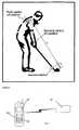
- the devicecould then be attached to the athlete's wrist, and it would be necessary to detect the point of release instead of point of impact. This could be done by using a pressure sensor or other switching device held in the hand or housed in a glove 200, as is shown in Figure 8 . The sensor would provide a signal when the projectile was released, and this would be used to trigger the device.
Landscapes
- Health & Medical Sciences (AREA)
- General Health & Medical Sciences (AREA)
- Physical Education & Sports Medicine (AREA)
- Golf Clubs (AREA)
- Measurement Of Mechanical Vibrations Or Ultrasonic Waves (AREA)
- Automatic Analysis And Handling Materials Therefor (AREA)
- Stringed Musical Instruments (AREA)
- Length Measuring Devices With Unspecified Measuring Means (AREA)
Abstract
Description
- The present invention relates to a device for analysing swing performance that is particularly applicable for use in golf training.
- Current systems of training for golfers are many and various. Some are purely mechanical, and help to train the user in technique by guiding the cub into a motion thought to be preferable to achieve good results. Others measure some aspect of the player's performance during practice, and provide information which the player can use to improve their swing.
- Many different schemes have been proposed for measuring and analysing various aspects of a golf swing. The depth of the analysis provided varies from a simple speed indicator to complex 3-dimensional motion and/or video analysis.
- Speed indicators are typically either free-standing or attach to, or form part of, the club. Free standing indicators typically employ a sensor arrangement that uses magnetic forces, light beams or microwave radar to measure club activity and motion. More complex methods use gyroscopes and multi-axis accelerometers or video cameras/recorders connected to a computer for analysis.
- Radar and light/laser devices are typically expensive, obtrusive, inaccurate, and can be difficult to set up. In the case of the radar devices, the point of measurement is not well defined. As the speed of, and therefore distance travelled by, the ball is dependent on the speed of the club head at impact, measurements at other times are not useful in this respect. Radar and laser devices also only produce speed information, which is, by itself, insufficient. More complex methods produce detailed results, but these require considerable skill and/or expertise to interpret, and so are not useful to the majority of golfers.
- Speed measuring devices exist, such as that disclosed in
US 3,815,427 , which fix to the club typically use one or more accelerometers to derive club head speed indirectly, by combining centripetal acceleration with radius of curvature. However these tend to be inaccurate for a number of reasons. - Firstly, they do not properly take into account the radius of curvature of the swing at the point of impact. Secondly, if the device is not attached close to the club head, then accurate measurement will not be possible. One reason for this difficulty is the inability to take account of shaft flexion. All these problems may be overcome by building the device into the head of the club, but this is expensive and very inconvenient.
- Some methods require knowledge of properties of the equipment, such as the weight of the club head, and/or the ball. Furthermore, none of the systems or devices known to the applicant take into account the slowing distance of the club (the distance travelled by the club head between reaching peak speed and the instant of impact with the ball) which clearly affects the accuracy of any measurements provided.
JP 10127845 A claim 1.- According to an aspect of the present invention, there is provided a swing performance analysis device according to
claim 1. - Preferably, the device comprises a housing securable to the shaft of the golf club, the accelerometer being mounted in the housing such that upon securement of the device to the shaft of the golf club, the axis of measurement of the accelerometer is parallel to the longitudinal axis of the shaft.
- The one or more parameters may include the length of the user's arm.
- Preferably, the processor is arranged to monitor measurement data from the accelerometer to determine when a swing is being taken and a point of impact, wherein measurement data corresponding to a swing being taken comprises a low frequency waveform and measurement data corresponding to a point of impact comprises a high frequency burst or sudden reduction in centripetal acceleration.
- A swing may be deemed to have started, when the output of the accelerometer reaches a predetermined threshold.
- In order to save energy, the processor may be arranged to sample measurement data more frequently once a swing is deemed to have started.
- The processor is preferably arranged to determine a peak speed of the swing, the peak speed comprising measurement data received from the accelerometer having a smaller magnitude than its predecessor.
- Upon detection of a point of impact, the processor is arranged to calculate club head velocity:

- where ai = measurement data from the accelerometer immediately preceding the point of impact
- r = distance to centre of rotation calculated in dependence on the one or more parameters.
- By fixing a. detachable device to the shaft, as close to the head of the club as possible, and making accurate measurements of the centripetal acceleration throughout the stroke, suitable mathematical formulae can be used to calculate the required quantities. This data should consist of at least the following: club head speed at impact, peak speed, and slowing distance. These results can be immediately presented to the golfer, clearly and unambiguously, and in such a way that they are easy to interpret, without requiring special skill or knowledge.
- The device would preferably be easy to set up, and would require only one measurement to be input by the user, which should, be easy to determine. It would be easy to clip onto the shaft of most clubs, and would be secure in use. The device should ideally work in both imperial and metric units, it should be reliable, and have adequate battery life.
- Being positioned close to the club head, having an accurate measurement capability, and properly taking into account the radius of curvature at the point of impact, the invention overcomes the problems of prior art.
- Any mass added to the club, especially near the head, is likely to adversely affect the balance of the club. It is therefore essential to keep the mass of the device as low as possible, preferably below 50 grams. This can be achieved by using highly integrated electronics and tightly controlled construction techniques.
- Embodiments of the present invention will now be described in detail, by way of example only, with reference to the accompanying drawings in which:
Figure 1 is a schematic diagram of an analysis device according to an embodiment of the present invention;Figures 2 and3 are perspective views of the analysis device ofFigure 1 ;Figure 4 is a perspective view of the device ofFigures 2 and3 secured to the shaft of a golf club;Figure 5 is a graph illustrating detection of analysis events;Figure 6 is a diagram illustrating factors used in calculating a radius factor;Figure 7 is a schematic diagram of an embodiment according to an aspect of the present invention in which selected functionality is provided by a remote device; and,Figure 8 is a schematic diagram of an alternate device according to an embodiment of the present invention.Figure 1 is a schematic diagram of an analysis device according to an embodiment of the present invention.- The
analysis device 10 includes a single-axis accelerometer 20, aprocessor 30, adisplay 40, anduser controls 50. Figures 2 and3 are perspective views of the analysis device ofFigure 1 ;- Preferably, the
device 10 is self-contained and includes anaperture 11 and securing means 12 enabling the device to be secured to the shaft of a golf club, as is shown inFigure 4 . - The device is secured on the
shaft 60 as close as possible to theclub head 70. - In order to measure centripetal acceleration along the axis of the
shaft 60, theaccelerometer 20 is orientated such that the measurement axis of the accelerometer is parallel to the axis of the shaft and the direction of the acceleration to be measured is towards the club head. - The output from the
accelerometer 20 is preconditioned by analogue circuitry, and the resultant signal is input to theprocessor 30 in which the signal is converted into the digital domain, and is processed to analyze the swing. Data on the swing is output to thedisplay 40. Preconditioning depends on the technology used in the accelerometer. Some will require temperature compensation, most will need amplification. Low pass filtering may also be desirable to control EMC susceptibility. The important thing is that the signal has sufficient magnitude and stability to properly drive the ADC, and thus achieve suitable measurement accuracy and resolution. - The user controls 50 are preferably push-button switches. One would switch the unit on and off, and reset the display after each stroke. The other would allow the user to scroll through the various results. A combination of presses would allow setting up of the
device 10 and any other settings which may be desired. - The user sets up the device by inputting a parameter corresponding to the length of their arm plus the length of the club. Following a swing, the device displays the peak speed, speed at impact and slowing distance on the
display 40. Using this information, the golfer is able to make adjustments to the swing to improve his or her technique by seeking to increase club head speed at impact and reduce slowing distance. - The accelerometer is oriented to measure centripetal acceleration along the length of the shaft. It produces an electrical output which is processed by a
processor 30. During a typical golf swing this output has the form shown inFigure 5 . - Two events occur during the stroke that are relevant: the swing itself, and the impact between the club head and the ball. During the swing the output changes smoothly and is characterised by a low frequency waveform. At the point of impact, very high tangential forces are produced, and these result in a disturbance in the sensor output which manifests as a high frequency burst. The difference in frequency content at the sensor output is used to distinguish between these two events.
- The
processor 30 monitors the accelerometer output at regular intervals. The swing is deemed to have started when the output of the accelerometer reaches a preset threshold. The monitoring of theprocessor 30 ensures that spurious outputs due to vibration, etc. do not cause invalid results. Once the swing has been determined to have begun, measurements are taken more frequently, as necessary to achieve the displayed distance resolution (at 100 mph, the club head typically travels 45 mm (almost 2 inches) every millisecond). Peak speed is deemed to have been reached when the succeeding measurement has a smaller magnitude than its predecessor. - Impact with the ball is detected by monitoring the rate of change of acceleration. When impact occurs, rate of change will rise (increase in magnitude). The actual change in the waveform may be a rise or a fall - the distinguishing feature is the frequency content. Characteristically, there will be an HF burst accompanied by a sudden fall in centripetal acceleration, as shown in
Figure 5 - Data is collected and stored in a memory until the impact is detected, at which time the most recent reading, corresponding to the acceleration just prior to impact is used to calculate club head velocity.
- The
processor 30 uses this data, together with the user-supplied parameter, to calculate the results, which are then presented to the user via the display device (e.g. a liquid crystal display) 40. Various results or combinations of results can be displayed, including peak speed, speed at impact and slowing distance. - The
processor 30 calculates the results as follows: - Peak Speed

- Impact Speed

- Slowing Distance

- Where: vpk = peak tangential velocity
- vi = tangential velocity at impact
- apk = peak centripetal acceleration
- ai = centripetal acceleration at time of impact
- r = distance to centre of rotation
- ti = time of impact
- tpk = time of peak centripetal acceleration
- d = slowing distance
- Note that during the very short time when the ball is in contact with the club head (~ 1 or 2 ms), tangential velocity approximates closely to linear speed.
- When a golf club is swung, the club head follows a curved path about two connected centres of rotation, as is illustrated in
Figure 6 . A first centre of rotation is located generally between the golfer's shoulders. A second centre of rotation is formed by the golfer's wrists. At the time when the club head strikes the golf ball, the club head is generally aligned with the centres of rotation, and the direction of motion of the golfer's hands is generally parallel to the direction of motion of the club head. - The radius factor r in the above equations is the distance between a notional centre of rotation and the accelerometer. The distance between the accelerometer and the notional centre of rotation will depend on factors including the length of the user's arm and length of the club shaft. The radius factor r is derived from the combined length of the arm and club.
- The user measures their arm length and the length of their club, adds these together, and enters this number into the
device 10 on setup. This would only need to be done once for each person/club combination and thedevice 10 may include a memory for maintaining a number of user/club profiles. A small correction factor is applied by the device to arrive at the true radius, and to correct for the displacement between the device and the centre of mass of the club head. - The correction factor is necessary to account for the fact that the point of measurement is a small distance (typically less than 100 mm) from the centre of mass of the cub head. The true velocity at the head is thus:

- Where: v = true tangential velocity of club head
- am = centripetal acceleration at measuring point
- r = distance from measuring point to centre of rotation
- r'= distance from measuring point to centre of mass of club head
- Other results could be calculated from the data gathered, e.g. swing count per hour / per session / per week, etc., average club head speed, average peak speed, average slowing distance, minimum slowing distance, maximum values, best strokes, swing tempo.
- Another way of calculating the radius factor r could be to use the player's height, which field trials have indicated show a good correlation to the radius.
- The
device 10 could include a memory and be pre-programmed to indicate to the user after each swing whether that swing was better or worse than some other swing, for example a stored 'best' value, or perhaps the previous swing. - The radius factor r could be entered as two separate numbers, arm length and club length. This would have the advantage of being able to enter just club length on change of clubs for the same person. A number of different arm lengths and club lengths could be stored and recalled as required.
- Data could be stored in the device, or on removable media, and later transferred to a personal digital assistant (PDA), Personal Computer (PC), or some other device for further analysis.
- Results could be transmitted wirelessly to another device, e.g. a PDA or a PC, using Bluetooth or the like, Indeed, results could be uploaded to a user's mobile telephone for storage and analysis. The
device 10 need not necessarily include adisplay 40 or use controls 50 as these could be integrated with a remote device such as amobile phone 100, as is shown inFigure 7 . A user configures a profile in theremote device 100 in advance by providing the data needed to calculate the radius factor r, this in turn is processed and uploaded wirelessly to thedevice 10 on the club which, after the stroke has been taken provides results back to theremote device 100. - The display could also take the form of a 'wristwatch' coupled to the measuring unit via a wireless data link.
- Embodiments of the present invention are also applicable to swing analysis for clubs other than drivers, to aid the golfer in achieving consistency in the weight of a stroke, and therefore improve the player's game.
- Additionally, embodiments of the present invention are also applicable for use in swing analysis in other sports involving swinging an implement (like a bat or club) and hitting a ball, e.g. tennis, baseball, etc.
- Embodiments of the present invention would also be applicable in sports where a rotational movement, but no impact, is involved (e.g. discus, hammer-throwing). In such cases, the device could then be attached to the athlete's wrist, and it would be necessary to detect the point of release instead of point of impact. This could be done by using a pressure sensor or other switching device held in the hand or housed in a
glove 200, as is shown inFigure 8 . The sensor would provide a signal when the projectile was released, and this would be used to trigger the device.


Claims (10)
- A swing performance analysis device (10) comprising a sole single axis accelerometer (20) and a processor (30), the accelerometer being securable on a shaft (60) of a golf cub substantially adjacent to the golf club's head (70) to measure centripetal acceleration, the accelerometer being arranged to communicate with a processor, wherein the processor is arranged to accept one or more parameters on the swing to be analysed and measurement data on the swing from the accelerometer, the processor being operative to determine the radius of curvature of the swing calculate in dependence on the one or more parameters and to determine one or more attributes on the swing in dependence on the radius and measurement data,characterised in that the one ore more attributes includes slowing distance, d:
 Where: vpk = peak tangential velocity =
 vi = tangential velocity at impact =
 ai = centripetal acceleration at time of impactapk = peak centripetal accelerationr = distance to centre of rotation.
 - A swing performance analysis device according to claim 1, wherein the device comprises a housing securable to the shaft of the golf club, the accelerometer being mounted in the housing such that upon securement of the device to the shaft of the golf club, the axis of measurement of the accelerometer is parallel to the longitudinal axis of the shaft.
- A swing performance analysis device according to any preceding claim, wherein the one or more parameters include the length of the user's arm.
- A swing performance analysis device according to claim 3, wherein the processor is arranged to monitor measurement data from the accelerometer to determine when a swing is being taken and a point of impact, wherein measurement data corresponding to a swing being taken comprises a low frequency waveform and measurement data corresponding to a point of impact comprises a high frequency burst or sudden reduction in centripetal acceleration.
- A swing performance analysis device according to claim 4, wherein a swing is deemed to have started when the output of the accelerometer reaches a predetermined threshold.
- A swing performance analysis device according to claim 5, wherein the processor being arranged to sample measurement data more frequently once a swing is deemed to have started.
- A swing performance analysis device according to claim 4, 5 or 6, wherein upon detection of a point of impact, the processor is arranged to calculate club head velocity by the formula:
 where ai = measurement data from the accelerometer immediately preceding the point of impactr = distance to centre of rotation calculated in dependence on the one or more parameters.
 - A swing performance analysis device according to any preceding claim, wherein the processor is arranged to determine a peak speed of the swing, the peak speed comprising measurement data received from the accelerometer having a smaller magnitude than its predecessor.
- A swing performance analysis device according to any preceding claim, wherein the processor is remote from the accelerometer.
- A swing performance analysis device according to claim 9, wherein the processor and accelerometer communicate wirelessly.


Applications Claiming Priority (2)
| Application Number | Priority Date | Filing Date | Title |
|---|---|---|---|
| GB0520373AGB2430890A (en) | 2005-10-06 | 2005-10-06 | Swing performance analysis device |
| PCT/GB2006/003711WO2007039748A2 (en) | 2005-10-06 | 2006-10-05 | Swing performance analysis device |
Publications (2)
| Publication Number | Publication Date |
|---|---|
| EP1977256A2 EP1977256A2 (en) | 2008-10-08 |
| EP1977256B1true EP1977256B1 (en) | 2009-05-06 |
Family
ID=35429948
Family Applications (1)
| Application Number | Title | Priority Date | Filing Date |
|---|---|---|---|
| EP06794662ANot-in-forceEP1977256B1 (en) | 2005-10-06 | 2006-10-05 | Swing performance analysis device |
Country Status (6)
| Country | Link |
|---|---|
| US (1) | US8052539B2 (en) |
| EP (1) | EP1977256B1 (en) |
| AT (1) | ATE430941T1 (en) |
| DE (1) | DE602006006726D1 (en) |
| GB (1) | GB2430890A (en) |
| WO (1) | WO2007039748A2 (en) |
Families Citing this family (68)
| Publication number | Priority date | Publication date | Assignee | Title |
|---|---|---|---|---|
| US9802129B2 (en)* | 2000-05-12 | 2017-10-31 | Wilbert Q. Murdock | Internet sports computer cellular device |
| US8303428B2 (en)* | 2007-02-15 | 2012-11-06 | Wagen Thomas A | Short game training device for use with golf club |
| US8589114B2 (en) | 2008-08-19 | 2013-11-19 | Angelo Gregory Papadourakis | Motion capture and analysis |
| US9149693B2 (en) | 2009-01-20 | 2015-10-06 | Nike, Inc. | Golf club and golf club head structures |
| US8668595B2 (en) | 2011-04-28 | 2014-03-11 | Nike, Inc. | Golf clubs and golf club heads |
| US9192831B2 (en) | 2009-01-20 | 2015-11-24 | Nike, Inc. | Golf club and golf club head structures |
| US20110306435A1 (en)* | 2009-02-23 | 2011-12-15 | Min Ho Seo | Golf swing action correcting unit, and a golf swing action correcting device comprising the same |
| US11117033B2 (en) | 2010-04-26 | 2021-09-14 | Wilbert Quinc Murdock | Smart system for display of dynamic movement parameters in sports and training |
| US8827824B2 (en) | 2010-08-26 | 2014-09-09 | Blast Motion, Inc. | Broadcasting system for broadcasting images with augmented motion data |
| US9247212B2 (en) | 2010-08-26 | 2016-01-26 | Blast Motion Inc. | Intelligent motion capture element |
| US9619891B2 (en) | 2010-08-26 | 2017-04-11 | Blast Motion Inc. | Event analysis and tagging system |
| US9646209B2 (en) | 2010-08-26 | 2017-05-09 | Blast Motion Inc. | Sensor and media event detection and tagging system |
| US9401178B2 (en) | 2010-08-26 | 2016-07-26 | Blast Motion Inc. | Event analysis system |
| US8944928B2 (en) | 2010-08-26 | 2015-02-03 | Blast Motion Inc. | Virtual reality system for viewing current and previously stored or calculated motion data |
| US9940508B2 (en) | 2010-08-26 | 2018-04-10 | Blast Motion Inc. | Event detection, confirmation and publication system that integrates sensor data and social media |
| US9604142B2 (en) | 2010-08-26 | 2017-03-28 | Blast Motion Inc. | Portable wireless mobile device motion capture data mining system and method |
| US9396385B2 (en) | 2010-08-26 | 2016-07-19 | Blast Motion Inc. | Integrated sensor and video motion analysis method |
| US8903521B2 (en) | 2010-08-26 | 2014-12-02 | Blast Motion Inc. | Motion capture element |
| US9418705B2 (en) | 2010-08-26 | 2016-08-16 | Blast Motion Inc. | Sensor and media event detection system |
| US9320957B2 (en) | 2010-08-26 | 2016-04-26 | Blast Motion Inc. | Wireless and visual hybrid motion capture system |
| US9039527B2 (en) | 2010-08-26 | 2015-05-26 | Blast Motion Inc. | Broadcasting method for broadcasting images with augmented motion data |
| US9076041B2 (en) | 2010-08-26 | 2015-07-07 | Blast Motion Inc. | Motion event recognition and video synchronization system and method |
| US8702516B2 (en) | 2010-08-26 | 2014-04-22 | Blast Motion Inc. | Motion event recognition system and method |
| US8994826B2 (en) | 2010-08-26 | 2015-03-31 | Blast Motion Inc. | Portable wireless mobile device motion capture and analysis system and method |
| US9607652B2 (en) | 2010-08-26 | 2017-03-28 | Blast Motion Inc. | Multi-sensor event detection and tagging system |
| US9626554B2 (en) | 2010-08-26 | 2017-04-18 | Blast Motion Inc. | Motion capture system that combines sensors with different measurement ranges |
| US8905855B2 (en) | 2010-08-26 | 2014-12-09 | Blast Motion Inc. | System and method for utilizing motion capture data |
| US9261526B2 (en) | 2010-08-26 | 2016-02-16 | Blast Motion Inc. | Fitting system for sporting equipment |
| US9406336B2 (en) | 2010-08-26 | 2016-08-02 | Blast Motion Inc. | Multi-sensor event detection system |
| US8465376B2 (en) | 2010-08-26 | 2013-06-18 | Blast Motion, Inc. | Wireless golf club shot count system |
| US8941723B2 (en) | 2010-08-26 | 2015-01-27 | Blast Motion Inc. | Portable wireless mobile device motion capture and analysis system and method |
| US9235765B2 (en) | 2010-08-26 | 2016-01-12 | Blast Motion Inc. | Video and motion event integration system |
| US9687705B2 (en) | 2010-11-30 | 2017-06-27 | Nike, Inc. | Golf club head or other ball striking device having impact-influencing body features |
| EP2646122B1 (en) | 2010-11-30 | 2015-03-18 | NIKE Innovate C.V. | Golf club heads or other ball striking devices having distributed impact response and a stiffened face plate |
| US9433844B2 (en) | 2011-04-28 | 2016-09-06 | Nike, Inc. | Golf clubs and golf club heads |
| US9409076B2 (en) | 2011-04-28 | 2016-08-09 | Nike, Inc. | Golf clubs and golf club heads |
| US9433845B2 (en) | 2011-04-28 | 2016-09-06 | Nike, Inc. | Golf clubs and golf club heads |
| US8986130B2 (en) | 2011-04-28 | 2015-03-24 | Nike, Inc. | Golf clubs and golf club heads |
| US9409073B2 (en) | 2011-04-28 | 2016-08-09 | Nike, Inc. | Golf clubs and golf club heads |
| US9925433B2 (en) | 2011-04-28 | 2018-03-27 | Nike, Inc. | Golf clubs and golf club heads |
| US9375624B2 (en) | 2011-04-28 | 2016-06-28 | Nike, Inc. | Golf clubs and golf club heads |
| WO2012158955A2 (en)* | 2011-05-19 | 2012-11-22 | NEWMAN, Harvey H. | Golf swing analyzer and analysis methods |
| CN107583254B (en) | 2011-08-23 | 2020-03-27 | 耐克创新有限合伙公司 | Golf club head with cavity |
| US8913134B2 (en) | 2012-01-17 | 2014-12-16 | Blast Motion Inc. | Initializing an inertial sensor using soft constraints and penalty functions |
| US8517850B1 (en) | 2012-12-11 | 2013-08-27 | Cobra Golf Incorporated | Golf club grip with device housing |
| US9053256B2 (en) | 2012-05-31 | 2015-06-09 | Nike, Inc. | Adjustable golf club and system and associated golf club heads and shafts |
| US9409068B2 (en) | 2012-05-31 | 2016-08-09 | Nike, Inc. | Adjustable golf club and system and associated golf club heads and shafts |
| JP6168279B2 (en)* | 2013-02-15 | 2017-07-26 | セイコーエプソン株式会社 | Analysis control device, motion analysis system, program, recording medium, and orientation adjusting method |
| US20140295983A1 (en)* | 2013-03-15 | 2014-10-02 | Butler Nooner | Exercise, training, and therapy tool and related systems and methods |
| US20140274439A1 (en) | 2013-03-15 | 2014-09-18 | Sanwood Llc | Impact Indication and Data Tracking Devices and Methods |
| US10520557B2 (en) | 2014-04-24 | 2019-12-31 | Arthrokinetic Institute, Llc | Systems, devices, and methods for recording and transmitting data |
| US20150367204A1 (en) | 2014-06-20 | 2015-12-24 | Nike, Inc. | Golf Club Head or Other Ball Striking Device Having Impact-Influencing Body Features |
| US10974121B2 (en) | 2015-07-16 | 2021-04-13 | Blast Motion Inc. | Swing quality measurement system |
| CA3031040C (en) | 2015-07-16 | 2021-02-16 | Blast Motion Inc. | Multi-sensor event correlation system |
| US9694267B1 (en) | 2016-07-19 | 2017-07-04 | Blast Motion Inc. | Swing analysis method using a swing plane reference frame |
| US11565163B2 (en) | 2015-07-16 | 2023-01-31 | Blast Motion Inc. | Equipment fitting system that compares swing metrics |
| US11577142B2 (en) | 2015-07-16 | 2023-02-14 | Blast Motion Inc. | Swing analysis system that calculates a rotational profile |
| US10124230B2 (en) | 2016-07-19 | 2018-11-13 | Blast Motion Inc. | Swing analysis method using a sweet spot trajectory |
| US10265602B2 (en) | 2016-03-03 | 2019-04-23 | Blast Motion Inc. | Aiming feedback system with inertial sensors |
| US10220285B2 (en) | 2016-05-02 | 2019-03-05 | Nike, Inc. | Golf clubs and golf club heads having a sensor |
| US10137347B2 (en) | 2016-05-02 | 2018-11-27 | Nike, Inc. | Golf clubs and golf club heads having a sensor |
| US10159885B2 (en) | 2016-05-02 | 2018-12-25 | Nike, Inc. | Swing analysis system using angular rate and linear acceleration sensors |
| US10226681B2 (en) | 2016-05-02 | 2019-03-12 | Nike, Inc. | Golf clubs and golf club heads having a plurality of sensors for detecting one or more swing parameters |
| US10786728B2 (en) | 2017-05-23 | 2020-09-29 | Blast Motion Inc. | Motion mirroring system that incorporates virtual environment constraints |
| USD849166S1 (en) | 2017-12-07 | 2019-05-21 | Ssg International, Llc | Golf putter grip |
| US10099101B1 (en) | 2017-12-07 | 2018-10-16 | Ssg International, Llc | Golf club grip with sensor housing |
| US10493340B1 (en)* | 2018-10-25 | 2019-12-03 | Acushnet Company | Wedge golf club fitting system |
| US12053682B2 (en) | 2021-12-30 | 2024-08-06 | Acushnet Company | Wedge golf club fitting system and method |
Family Cites Families (10)
| Publication number | Priority date | Publication date | Assignee | Title |
|---|---|---|---|---|
| US5688183A (en)* | 1992-05-22 | 1997-11-18 | Sabatino; Joseph | Velocity monitoring system for golf clubs |
| JPH10127845A (en)* | 1996-10-30 | 1998-05-19 | Pentel Kk | Golf practice equipment |
| US6045364A (en)* | 1997-05-19 | 2000-04-04 | Dugan; Brian M. | Method and apparatus for teaching proper swing tempo |
| US6173610B1 (en)* | 1998-12-23 | 2001-01-16 | Robert L. Pace | Sports swing impact speed indicator |
| US6441745B1 (en)* | 1999-03-22 | 2002-08-27 | Cassen L. Gates | Golf club swing path, speed and grip pressure monitor |
| US6224493B1 (en) | 1999-05-12 | 2001-05-01 | Callaway Golf Company | Instrumented golf club system and method of use |
| GB0109836D0 (en)* | 2001-04-21 | 2001-06-13 | Kimber Peter J | Velocity display device |
| US20020173364A1 (en)* | 2001-05-17 | 2002-11-21 | Bogie Boscha | Apparatus for measuring dynamic characteristics of golf game and method for asessment and analysis of hits and movements in golf |
| US7736242B2 (en)* | 2004-03-23 | 2010-06-15 | Nike, Inc. | System for determining performance characteristics of a golf swing |
| US7771263B2 (en)* | 2004-09-09 | 2010-08-10 | Telford Golf Enterprises, LLC | Portable swing speed analyzer |
- 2005
- 2005-10-06GBGB0520373Apatent/GB2430890A/ennot_activeWithdrawn
- 2006
- 2006-10-05WOPCT/GB2006/003711patent/WO2007039748A2/enactiveApplication Filing
- 2006-10-05EPEP06794662Apatent/EP1977256B1/ennot_activeNot-in-force
- 2006-10-05DEDE602006006726Tpatent/DE602006006726D1/ennot_activeExpired - Fee Related
- 2006-10-05USUS12/089,392patent/US8052539B2/ennot_activeExpired - Fee Related
- 2006-10-05ATAT06794662Tpatent/ATE430941T1/ennot_activeIP Right Cessation
Also Published As
| Publication number | Publication date |
|---|---|
| DE602006006726D1 (en) | 2009-06-18 |
| US20090131190A1 (en) | 2009-05-21 |
| ATE430941T1 (en) | 2009-05-15 |
| GB2430890A (en) | 2007-04-11 |
| GB0520373D0 (en) | 2005-11-16 |
| US8052539B2 (en) | 2011-11-08 |
| WO2007039748A2 (en) | 2007-04-12 |
| EP1977256A2 (en) | 2008-10-08 |
| WO2007039748A3 (en) | 2007-06-14 |
Similar Documents
| Publication | Publication Date | Title |
|---|---|---|
| EP1977256B1 (en) | Swing performance analysis device | |
| US20240091589A1 (en) | Integrated portable device and method implementing an accelerometer for analyzing biomechanical parameters of a stride | |
| US9884233B2 (en) | Golf clubs and golf club heads having digital lie and/or other angle measuring equipment | |
| US7140248B1 (en) | Speed measuring device and method | |
| US5688183A (en) | Velocity monitoring system for golf clubs | |
| US8840483B1 (en) | Device, system, and method for evaluation of a swing of a piece of athletic equipment | |
| EP1991877B1 (en) | Method and apparatus for estimating a motion parameter | |
| US8265900B2 (en) | Motion analysis device for sports | |
| US9155935B2 (en) | Gyroscopic exercise ball | |
| JPH09215808A (en) | Practice device for swing type exercise tool, and swing type exercise tool | |
| KR100634523B1 (en) | Exercise motion monitoring device and method | |
| US20030017882A1 (en) | Sport apparatus with impact sensing and display | |
| US20060211523A1 (en) | Bat speed sensing device and methods | |
| KR101736489B1 (en) | System for analyzing sport exercise by club device based on complex motion detecting senssor | |
| JP2012200540A (en) | Swing analyzing system and swing analyzing apparatus | |
| KR20060060436A (en) | Golf club with putting impact measuring device, measuring method and measuring device | |
| KR100856426B1 (en) | Exercise device trajectory measuring device using a plurality of acceleration sensors and method | |
| KR20110006005A (en) | Angular velocity sensor for golf | |
| US20080066545A1 (en) | Speed measuring device | |
| HK1226931A1 (en) | Integrated portable device and method using an accelerometer to analyze biomechanical parameters of the stride | |
| HK1227270A1 (en) | Integrated portable device and method using an accelerometer to analyse biomechanical parameters of the stride | |
| CA2385367A1 (en) | Sport apparatus with impact sensing and display |
Legal Events
| Date | Code | Title | Description |
|---|---|---|---|
| PUAI | Public reference made under article 153(3) epc to a published international application that has entered the european phase | Free format text:ORIGINAL CODE: 0009012 | |
| 17P | Request for examination filed | Effective date:20080331 | |
| AK | Designated contracting states | Kind code of ref document:A2 Designated state(s):AT BE BG CH CY CZ DE DK EE ES FI FR GB GR HU IE IS IT LI LT LU LV MC NL PL PT RO SE SI SK TR | |
| GRAP | Despatch of communication of intention to grant a patent | Free format text:ORIGINAL CODE: EPIDOSNIGR1 | |
| GRAS | Grant fee paid | Free format text:ORIGINAL CODE: EPIDOSNIGR3 | |
| GRAA | (expected) grant | Free format text:ORIGINAL CODE: 0009210 | |
| AK | Designated contracting states | Kind code of ref document:B1 Designated state(s):AT BE BG CH CY CZ DE DK EE ES FI FR GB GR HU IE IS IT LI LT LU LV MC NL PL PT RO SE SI SK TR | |
| REG | Reference to a national code | Ref country code:GB Ref legal event code:FG4D | |
| REG | Reference to a national code | Ref country code:CH Ref legal event code:EP | |
| REG | Reference to a national code | Ref country code:IE Ref legal event code:FG4D | |
| REF | Corresponds to: | Ref document number:602006006726 Country of ref document:DE Date of ref document:20090618 Kind code of ref document:P | |
| PG25 | Lapsed in a contracting state [announced via postgrant information from national office to epo] | Ref country code:PT Free format text:LAPSE BECAUSE OF FAILURE TO SUBMIT A TRANSLATION OF THE DESCRIPTION OR TO PAY THE FEE WITHIN THE PRESCRIBED TIME-LIMIT Effective date:20090906 Ref country code:LT Free format text:LAPSE BECAUSE OF FAILURE TO SUBMIT A TRANSLATION OF THE DESCRIPTION OR TO PAY THE FEE WITHIN THE PRESCRIBED TIME-LIMIT Effective date:20090506 Ref country code:FI Free format text:LAPSE BECAUSE OF FAILURE TO SUBMIT A TRANSLATION OF THE DESCRIPTION OR TO PAY THE FEE WITHIN THE PRESCRIBED TIME-LIMIT Effective date:20090506 Ref country code:ES Free format text:LAPSE BECAUSE OF FAILURE TO SUBMIT A TRANSLATION OF THE DESCRIPTION OR TO PAY THE FEE WITHIN THE PRESCRIBED TIME-LIMIT Effective date:20090817 Ref country code:AT Free format text:LAPSE BECAUSE OF FAILURE TO SUBMIT A TRANSLATION OF THE DESCRIPTION OR TO PAY THE FEE WITHIN THE PRESCRIBED TIME-LIMIT Effective date:20090506 | |
| NLV1 | Nl: lapsed or annulled due to failure to fulfill the requirements of art. 29p and 29m of the patents act | ||
| PG25 | Lapsed in a contracting state [announced via postgrant information from national office to epo] | Ref country code:SE Free format text:LAPSE BECAUSE OF FAILURE TO SUBMIT A TRANSLATION OF THE DESCRIPTION OR TO PAY THE FEE WITHIN THE PRESCRIBED TIME-LIMIT Effective date:20090806 Ref country code:NL Free format text:LAPSE BECAUSE OF FAILURE TO SUBMIT A TRANSLATION OF THE DESCRIPTION OR TO PAY THE FEE WITHIN THE PRESCRIBED TIME-LIMIT Effective date:20090506 Ref country code:LV Free format text:LAPSE BECAUSE OF FAILURE TO SUBMIT A TRANSLATION OF THE DESCRIPTION OR TO PAY THE FEE WITHIN THE PRESCRIBED TIME-LIMIT Effective date:20090506 Ref country code:PL Free format text:LAPSE BECAUSE OF FAILURE TO SUBMIT A TRANSLATION OF THE DESCRIPTION OR TO PAY THE FEE WITHIN THE PRESCRIBED TIME-LIMIT Effective date:20090506 Ref country code:IS Free format text:LAPSE BECAUSE OF FAILURE TO SUBMIT A TRANSLATION OF THE DESCRIPTION OR TO PAY THE FEE WITHIN THE PRESCRIBED TIME-LIMIT Effective date:20090906 Ref country code:SI Free format text:LAPSE BECAUSE OF FAILURE TO SUBMIT A TRANSLATION OF THE DESCRIPTION OR TO PAY THE FEE WITHIN THE PRESCRIBED TIME-LIMIT Effective date:20090506 | |
| PG25 | Lapsed in a contracting state [announced via postgrant information from national office to epo] | Ref country code:CZ Free format text:LAPSE BECAUSE OF FAILURE TO SUBMIT A TRANSLATION OF THE DESCRIPTION OR TO PAY THE FEE WITHIN THE PRESCRIBED TIME-LIMIT Effective date:20090506 Ref country code:RO Free format text:LAPSE BECAUSE OF FAILURE TO SUBMIT A TRANSLATION OF THE DESCRIPTION OR TO PAY THE FEE WITHIN THE PRESCRIBED TIME-LIMIT Effective date:20090506 Ref country code:EE Free format text:LAPSE BECAUSE OF FAILURE TO SUBMIT A TRANSLATION OF THE DESCRIPTION OR TO PAY THE FEE WITHIN THE PRESCRIBED TIME-LIMIT Effective date:20090506 Ref country code:DK Free format text:LAPSE BECAUSE OF FAILURE TO SUBMIT A TRANSLATION OF THE DESCRIPTION OR TO PAY THE FEE WITHIN THE PRESCRIBED TIME-LIMIT Effective date:20090506 | |
| PG25 | Lapsed in a contracting state [announced via postgrant information from national office to epo] | Ref country code:BE Free format text:LAPSE BECAUSE OF FAILURE TO SUBMIT A TRANSLATION OF THE DESCRIPTION OR TO PAY THE FEE WITHIN THE PRESCRIBED TIME-LIMIT Effective date:20090506 Ref country code:SK Free format text:LAPSE BECAUSE OF FAILURE TO SUBMIT A TRANSLATION OF THE DESCRIPTION OR TO PAY THE FEE WITHIN THE PRESCRIBED TIME-LIMIT Effective date:20090506 | |
| PLBE | No opposition filed within time limit | Free format text:ORIGINAL CODE: 0009261 | |
| STAA | Information on the status of an ep patent application or granted ep patent | Free format text:STATUS: NO OPPOSITION FILED WITHIN TIME LIMIT | |
| PG25 | Lapsed in a contracting state [announced via postgrant information from national office to epo] | Ref country code:BG Free format text:LAPSE BECAUSE OF FAILURE TO SUBMIT A TRANSLATION OF THE DESCRIPTION OR TO PAY THE FEE WITHIN THE PRESCRIBED TIME-LIMIT Effective date:20090806 | |
| 26N | No opposition filed | Effective date:20100209 | |
| PG25 | Lapsed in a contracting state [announced via postgrant information from national office to epo] | Ref country code:MC Free format text:LAPSE BECAUSE OF NON-PAYMENT OF DUE FEES Effective date:20091031 | |
| REG | Reference to a national code | Ref country code:IE Ref legal event code:MM4A | |
| REG | Reference to a national code | Ref country code:FR Ref legal event code:ST Effective date:20100630 | |
| PG25 | Lapsed in a contracting state [announced via postgrant information from national office to epo] | Ref country code:DE Free format text:LAPSE BECAUSE OF NON-PAYMENT OF DUE FEES Effective date:20100501 Ref country code:FR Free format text:LAPSE BECAUSE OF NON-PAYMENT OF DUE FEES Effective date:20091102 | |
| PG25 | Lapsed in a contracting state [announced via postgrant information from national office to epo] | Ref country code:GR Free format text:LAPSE BECAUSE OF FAILURE TO SUBMIT A TRANSLATION OF THE DESCRIPTION OR TO PAY THE FEE WITHIN THE PRESCRIBED TIME-LIMIT Effective date:20090807 Ref country code:IE Free format text:LAPSE BECAUSE OF NON-PAYMENT OF DUE FEES Effective date:20091005 | |
| PG25 | Lapsed in a contracting state [announced via postgrant information from national office to epo] | Ref country code:IT Free format text:LAPSE BECAUSE OF FAILURE TO SUBMIT A TRANSLATION OF THE DESCRIPTION OR TO PAY THE FEE WITHIN THE PRESCRIBED TIME-LIMIT Effective date:20090506 | |
| PG25 | Lapsed in a contracting state [announced via postgrant information from national office to epo] | Ref country code:LU Free format text:LAPSE BECAUSE OF NON-PAYMENT OF DUE FEES Effective date:20091005 | |
| REG | Reference to a national code | Ref country code:CH Ref legal event code:PL | |
| PG25 | Lapsed in a contracting state [announced via postgrant information from national office to epo] | Ref country code:HU Free format text:LAPSE BECAUSE OF FAILURE TO SUBMIT A TRANSLATION OF THE DESCRIPTION OR TO PAY THE FEE WITHIN THE PRESCRIBED TIME-LIMIT Effective date:20091107 | |
| PG25 | Lapsed in a contracting state [announced via postgrant information from national office to epo] | Ref country code:CH Free format text:LAPSE BECAUSE OF NON-PAYMENT OF DUE FEES Effective date:20101031 Ref country code:LI Free format text:LAPSE BECAUSE OF NON-PAYMENT OF DUE FEES Effective date:20101031 | |
| PG25 | Lapsed in a contracting state [announced via postgrant information from national office to epo] | Ref country code:TR Free format text:LAPSE BECAUSE OF FAILURE TO SUBMIT A TRANSLATION OF THE DESCRIPTION OR TO PAY THE FEE WITHIN THE PRESCRIBED TIME-LIMIT Effective date:20090506 | |
| PG25 | Lapsed in a contracting state [announced via postgrant information from national office to epo] | Ref country code:CY Free format text:LAPSE BECAUSE OF FAILURE TO SUBMIT A TRANSLATION OF THE DESCRIPTION OR TO PAY THE FEE WITHIN THE PRESCRIBED TIME-LIMIT Effective date:20090506 | |
| PGFP | Annual fee paid to national office [announced via postgrant information from national office to epo] | Ref country code:GB Payment date:20161125 Year of fee payment:11 | |
| GBPC | Gb: european patent ceased through non-payment of renewal fee | Effective date:20171005 | |
| PG25 | Lapsed in a contracting state [announced via postgrant information from national office to epo] | Ref country code:GB Free format text:LAPSE BECAUSE OF NON-PAYMENT OF DUE FEES Effective date:20171005 |