EP1976246B1 - Multi-button control headset for a mobile communication device - Google Patents
Multi-button control headset for a mobile communication deviceDownload PDFInfo
- Publication number
- EP1976246B1 EP1976246B1EP07105171AEP07105171AEP1976246B1EP 1976246 B1EP1976246 B1EP 1976246B1EP 07105171 AEP07105171 AEP 07105171AEP 07105171 AEP07105171 AEP 07105171AEP 1976246 B1EP1976246 B1EP 1976246B1
- Authority
- EP
- European Patent Office
- Prior art keywords
- headset
- control signal
- mobile communication
- communication device
- button
- Prior art date
- Legal status (The legal status is an assumption and is not a legal conclusion. Google has not performed a legal analysis and makes no representation as to the accuracy of the status listed.)
- Active
Links
- 238000010295mobile communicationMethods0.000titleclaimsabstractdescription54
- 239000003990capacitorSubstances0.000claimsdescription7
- 230000009977dual effectEffects0.000claimsdescription3
- 238000003079width controlMethods0.000claimsdescription3
- 230000003213activating effectEffects0.000claimsdescription2
- 230000005540biological transmissionEffects0.000claimsdescription2
- 230000005669field effectEffects0.000claimsdescription2
- 238000010586diagramMethods0.000description8
- 238000000034methodMethods0.000description8
- 230000001419dependent effectEffects0.000description2
- 230000008569processEffects0.000description2
- 230000004044responseEffects0.000description2
- 230000004075alterationEffects0.000description1
- 230000008901benefitEffects0.000description1
- 239000004020conductorSubstances0.000description1
- 238000011982device technologyMethods0.000description1
- 210000005069earsAnatomy0.000description1
- 230000006870functionEffects0.000description1
- 230000002045lasting effectEffects0.000description1
- 238000012986modificationMethods0.000description1
- 230000004048modificationEffects0.000description1
- 230000002035prolonged effectEffects0.000description1
- 238000012552reviewMethods0.000description1
- 238000006467substitution reactionMethods0.000description1
Images


Classifications
- H—ELECTRICITY
- H04—ELECTRIC COMMUNICATION TECHNIQUE
- H04M—TELEPHONIC COMMUNICATION
- H04M1/00—Substation equipment, e.g. for use by subscribers
- H04M1/60—Substation equipment, e.g. for use by subscribers including speech amplifiers
- H04M1/6033—Substation equipment, e.g. for use by subscribers including speech amplifiers for providing handsfree use or a loudspeaker mode in telephone sets
- H04M1/6041—Portable telephones adapted for handsfree use
- H04M1/6058—Portable telephones adapted for handsfree use involving the use of a headset accessory device connected to the portable telephone
- H—ELECTRICITY
- H04—ELECTRIC COMMUNICATION TECHNIQUE
- H04R—LOUDSPEAKERS, MICROPHONES, GRAMOPHONE PICK-UPS OR LIKE ACOUSTIC ELECTROMECHANICAL TRANSDUCERS; DEAF-AID SETS; PUBLIC ADDRESS SYSTEMS
- H04R1/00—Details of transducers, loudspeakers or microphones
- H04R1/10—Earpieces; Attachments therefor ; Earphones; Monophonic headphones
- H04R1/1041—Mechanical or electronic switches, or control elements
- H—ELECTRICITY
- H04—ELECTRIC COMMUNICATION TECHNIQUE
- H04R—LOUDSPEAKERS, MICROPHONES, GRAMOPHONE PICK-UPS OR LIKE ACOUSTIC ELECTROMECHANICAL TRANSDUCERS; DEAF-AID SETS; PUBLIC ADDRESS SYSTEMS
- H04R1/00—Details of transducers, loudspeakers or microphones
- H04R1/10—Earpieces; Attachments therefor ; Earphones; Monophonic headphones
- H04R1/1083—Reduction of ambient noise
- H—ELECTRICITY
- H04—ELECTRIC COMMUNICATION TECHNIQUE
- H04R—LOUDSPEAKERS, MICROPHONES, GRAMOPHONE PICK-UPS OR LIKE ACOUSTIC ELECTROMECHANICAL TRANSDUCERS; DEAF-AID SETS; PUBLIC ADDRESS SYSTEMS
- H04R2201/00—Details of transducers, loudspeakers or microphones covered by H04R1/00 but not provided for in any of its subgroups
- H04R2201/10—Details of earpieces, attachments therefor, earphones or monophonic headphones covered by H04R1/10 but not provided for in any of its subgroups
- H04R2201/107—Monophonic and stereophonic headphones with microphone for two-way hands free communication
- H—ELECTRICITY
- H04—ELECTRIC COMMUNICATION TECHNIQUE
- H04R—LOUDSPEAKERS, MICROPHONES, GRAMOPHONE PICK-UPS OR LIKE ACOUSTIC ELECTROMECHANICAL TRANSDUCERS; DEAF-AID SETS; PUBLIC ADDRESS SYSTEMS
- H04R2420/00—Details of connection covered by H04R, not provided for in its groups
- H04R2420/09—Applications of special connectors, e.g. USB, XLR, in loudspeakers, microphones or headphones
Definitions
- the present inventionrelates generally to headsets for a mobile communication device. More particularly, the present invention relates to a headset for a mobile communication device having a multi-button control and a standard headset jack.
- a headsetIn order for users to listen to an MP3 player, a headset is typically required which preferably includes a remote control so that the user is able to control the MP3 player within the mobile communication device.
- these headsetsare typically individualized for each mobile communication device.
- Existing headsetsinclude non-standard headset jacks which are then plugged into a corresponding slot within the unique mobile communication device. Therefore users are required to buy a specific headset which is dependent on the mobile communication device they are using.
- headsets with standard jacks which are used with mobile communication deviceshave only a single button which is used to mute a call or to initiate voice activated dialing.
- a single press, or a long presscan activate different functions.
- these single button controlscan only provide two different control signals.
- some headsets with multiple button controlsare implemented with non-standard jacks and thusly, the mobile communication devices are required to be updated in order to be able to receive the non-standard jack. Therefore, additional hardware is required in each mobile communication device in order to receive the non-standard jack. Additional conductors are also required in each of the headsets.
- US-A-2003/008311 Adiscloses a navigational control for a wireless computer resource access device.
- the controlincludes headphones and a multiple buttons.
- a connector secured to the body of the controlconnects the control to a wireless access device.
- the inventionmay be directed at a headset for a mobile communication device having a multi-button control and is implemented with a standard headset jack.
- the multi-buttons controlmay be decoded by a microprocessor after which an encoded signal is then transmitted, via the microphone line from the processor to the handset. In this manner, by using the standard jack, no additional hardware is required in the handset. Only software to decode the signal on the microphone input may be required on the handset.
- a headset having a set of speakers for transmitting sound to a usercomprising a standard headset jack plug a multi-button control capable of activating commands on a mobile communication device, the mobile communication device having means for receiving said standard headset jack plug, the multi-button control including: a set of buttons, each representing one of said commands; and a controller, connected to each button of said set of buttons; wherein when said controller detects the depression of one of said buttons in said set of buttons, said controller determines which button was pressed and transmits a control signal via a microphone line to said standard headset jack plug corresponding to said button.
- the controllermay be a processor or an application specific integrated circuit (ASIC).
- ASICapplication specific integrated circuit
- control signal being transmittedmay be encoded in an encoding control signal mode whereby the encoding control signal mode is selected from a group consisting of a multiple presses control signal mode, a pulse train control signal mode, a unique frequency control signal mode, a dual tone multiple frequency (DTMF) control signal mode and a pulse width control signal mode.
- encoding control signal modeis selected from a group consisting of a multiple presses control signal mode, a pulse train control signal mode, a unique frequency control signal mode, a dual tone multiple frequency (DTMF) control signal mode and a pulse width control signal mode.
- the controllermay be a database for storing control signal information associated with each of said set of buttons; and a module for associating said button depression with a control signal.
- a headset for a mobile communication devicecomprising a set of speakers for transmitting sound from the mobile communication device to a user; a multi-button control for controlling sound from the mobile communication device; and a standard jack plug for connecting the headset to the mobile communication device and for transmitting signals from the multi-button control to the mobile communication device to provide sound to the speakers.
- the present embodimentprovides a method and system for a headset for a mobile communication device.
- the headsetincludes a multi-button control and uses a standard jack for connecting to the mobile communication device.
- FIG. 1a schematic diagram of a mobile communication device, or handset, 10 having a headset 12 thereby connected is provided.
- the headset 12further comprises a multiple button controller 14 having a plurality of buttons 16.
- the number of buttonsis theoretically limitless however, the number is dictated by the size of the controller 14.
- the headset 12further includes at least one ear bud 18 each housing a speaker (as shown in Figure 2 ).
- the headset 12is connected to the mobile communication device 10 via standard jack.
- a microphone 15is also included in the headset 12.
- circuitry 20, typically mounted to a printed circuit board assembly 21, for a standard headset 12is shown.
- the headset 12includes a standard jack, or plug, 22 for connecting the headset to the handset.
- the plug 22comprises a microphone portion 24, a left speaker portion 26, a right speaker portion 28 and a ground portion 30.
- the jack 22is connected to the circuitry 20 via a plurality of wires 32.
- the circuitry 20comprises a set of connectors 34 for receiving the wires 32 from their corresponding locations within the jack 22.
- the microphone connector 34ais connected to a first capacitor 36 and an inductor 38.
- An output of the inductor 38is connected to plurality of elements connected in parallel.
- the plurality of elementsincludes a switch 40, a zener diode 42, a second capacitor 44, a microphone 46 and a third capacitor 48.
- a second inductor 50is located between the ground connector 34b and the output of the parallel elements.
- the output from the second inductor 50is connected to ground along with one side of a pair of speakers 52.
- the left speaker portion connector 34c and the right speaker portion connector 34dare also connected to their respective, left and right speakers 52.
- the speakersare typically located within the ear buds 18 of the headset 12 which are then inserted into a user's ears so that they may listen of the output from the mobile communication device.
- the zener diode 42is used to control the electrostatic discharge (ESD) which may be experienced within the headset 12.
- ESDelectrostatic discharge
- the inductor 38 and the first capacitor 36provide a wide band filter for the various General Packet radio Services (GPRS) bands. This filter reduces and/or prevents the headset from picking up and transmitting GSM pulses via the microphone line. This is also known as GSM buzz.
- the switch 40shorts out the microphone bias current which is detected by the handset as a signal.
- FIG. 3a schematic diagram of an embodiment of a headset 12 having a multi-button control 60 in accordance with one embodiment is shown.
- the headset 12is implemented with the standard headset jack 22 for connection with the mobile communication device 10.
- the circuitry 62 for implementing the multi-button control 60is shown connected to the standard headset circuitry 20 of Figure 2 with one substitution.
- the switch 40is replaced with a Field-Effect Transistor (FET) 64.
- FETField-Effect Transistor
- the implementation of the multi-button control using a standard headset and standard jackprovides the benefit that mobile communication devices do not have to be altered in order to operate with the headset. In this manner, since the mobile communication device does not have to be updated to include extra hardware to receive the headset jack, the mobile communication device may be able to receive the headset disclosed herein or existing headsets with standard jacks and one control button.
- the handsetpreferably includes circuitry to make this determination.
- a predetermined signalmay be transmitted by the headset to be decoded by the handset. This may be implemented by simply connecting an output of a controller 66 to the microphone portion of the plug output of the processor.
- a filter network 71may also be located along this connection in order to reduce noise.
- the circuitry 62includes the controller 66, such as a processor, preferably having low power consumption and a battery 68.
- the battery 68is preferably a rechargeable battery or a super capacitor which may be charged by a microphone bias when the headset is connected to the mobile communication device. If a microphone bias is used, a voltage boost circuit is likely to be required to boost the voltage on the microphone bias to above 1.8 V. Alternatively, the battery may be a one-time use battery and replaced when the power has been entirely discharged from the battery 68.
- a series of switches 70representing each button on the multi-button control, is connected to the processor 66.
- the switches 70have been labeled as B1, B2, B3, B4, B5 and B6.
- B1may represent a mute button
- B2may represent a volume up button
- B3may represent a volume down button
- B4may represent a rewind button
- B5may represent a fast forward button
- B6may represent a play/stop button.
- the number of switchesis limitless but is dependent on the physical size of the multi-button control.
- Each of the switchesis also connected to ground 72.
- a memory, or database 67for storing control information and a module 69 for determining which switch 70 has been pressed.
- an output of the processor 66is connected to the FET 64. As will be described below with respect to the operation of the control 60, this connection provides the necessary signals to control the handset.
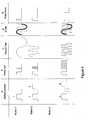
- FIG. 4provides examples of various methods of encoding the control signals being transmitted from the headset to the handset.
- Encoding control signal mode Ais directed at multiple presses
- encoding control signal mode Bis directed at pulse trains
- encoding control signal mode Cis directed at unique frequencies
- encoding control signal mode Dis directed a dual tone multiple frequency (DTMF)
- encoding control signal mode Eis directed at pulse width. It will be understood that each headset preferably operates in only one of the encoding control signal modes but in some embodiments, the headset may operate under multiple control signal modes depending on the required functionality.
- DTMFdual tone multiple frequency
- the circuitryis implemented for a multi-button control 60 operating under control signal mode A, control signal mode B or control signal mode E, as shown in Figure 4 .
- each headsetpreferably operates in a single control signal mode.
- some embodimentsmay employ multiple control signal modes.
- the software module 69determines B6 was pressed and accesses the database/memory 67 to determine the signal that needs to be transmitted from the multi-button control to play music.
- the signal corresponding to B6 for mode Ais a series of 6 pulses.
- the pulsesare then transmitted from the processor 66 to the FET 64.
- the pulsesare recognized by the FET 64 which then translates this pulse signal to the jack 22 (step 206) by shorting out the microphone to ground.
- the jack 22then transmits this information to the handset (step 208 ) which receives the pulse signal.
- a processor within the handsetthen processes the pulse signal to determine the command corresponding to the signal transmitted (step 209).
- the processordetermines that a play music command has been issued and then executes the command and transmits the response to the headset (step 211). Therefore, in this example, the mobile communication device plays music which is then transmitted back through the jack 22 to the headset which then receives the response and transmits the music to the speakers (step 210).
- the useris then able to enjoy listening to music on their headset. Similarly, if music is already playing, the user may choose to stop the music, turn the volume up or down by pressing the relevant button. As before, the method outlined in Figure 6 is performed to transmit the necessary signal to the handset to have the command be performed.
- a start pulseis typically transmitted to the FET indicating that a button has been pressed.
- the start pulseis then followed up with a series of pulses corresponding to the button number that was pressed. For instance if B1 is pressed, a single pulse is provided after the start pulse, if B2 is pressed, two pulses are provided. Similar pulse streams are provided for buttons B3, B4, B5 and B6.
- the start pulsemay be a 20ms pulse with a 10ms break before the transmission of the stream of control signal pulses, each pulse lasting for 1 ms.
- the circuitrywhen square wave pulses are used, the circuitry further includes a set of electronic elements which limit the slew rate of the square wave pulse in order to reduce the potential of the buttons from being heard in the audio transmitted to the speakers. In one embodiment, this may be implemented by adding a resistor/capacitor (RC) network between the FET and the processor 66. Finer slew rate control may be implemented by standard pulse width modulation (PWM) methods.
- PWMpulse width modulation
- the pulse trainis then transmitted from the FET to the headset 10 via the jack 22.
- the processor within the headset 10recognizes the start pulse and processes the following series of pulses to determine which button is pressed. After determining the command from the control, the mobile communication proceeds to execute the demand and the result is transmitted to the user via the speakers.
- FIG. 5a second embodiment of a multiple button control 14 for a mobile communication device 10 is shown.
- the output of the processoris directed connected directly to the jack 22, however the output is transmitted through a voltage divider 74 which is used to ensure that the signal being transmitted to the jack is at a predetermined level comparable to the microphone output.
- Operation of the embodimentis in an identical manner with respect to the method outlined in Figure 6 .
- the nature of the signals being transmitted by the processordiffers.
- the control signalswhen operating in Mode C, the control signals are transmitted at different frequencies such that the jack transmits the signal to the headset which deciphers the frequency and then performs the requested task.
- the output of the processormay also be connected to the FET 64.
- the processor 66transmits a signal at 3400Hz which is then received by the handset 10 via the jack 22. Once the handset receives a signal at 3400Hz, the processor recognizes that B1 has been pressed. Similarly, if B2 is pressed, a signal is transmitted at 3600Hz to the mobile communication device. In order to prevent any interference, each of the frequencies which are selected and associated with the buttons are outside of the audible range so the user does not experience any interference or distraction.
- the battery 68allows the control to be self-sufficient and does not drain the battery within the mobile communication device. Therefore by utilizing a low power processor, the life of the battery 68 is prolonged and does not have to be changed on a constant basis. The importance of the battery is that no additional connection is required from the handset to provide power to the processor in the headset.
- the signalsare selected and differentiated using DTMF.
- the processor 66may be replaced by an Application Specific Integrated Circuit (ASIC) to lower cost, power consumption and size of the control 16.
- ASICApplication Specific Integrated Circuit
- Mode Amay be used to control an MP3 player while Mode B may be used as a joystick to play a game on the mobile communication device.
- the multiple button controlincludes a switch or control to determine which mode the headset is operating in order to ensure that the encoding is performed correctly by the processor 66.
- Another embodimentmay include the controller 16 being used as a multi-media control in one mode and as a phone dialer in a second mode.
- the embodiment having multiple encoding control signal modesmay also allow the headset to have a more universal use in that different handsets may require specific encoding control signal modes.
- mobile communication devicesmay operate currently under one mode but in future implementations, may operate under a second mode.
- the headsetmay be used for both the currently and future versions of a mobile communication device provide more flexibility to the user.
Landscapes
- Engineering & Computer Science (AREA)
- Signal Processing (AREA)
- Physics & Mathematics (AREA)
- Acoustics & Sound (AREA)
- Telephone Function (AREA)
- Mobile Radio Communication Systems (AREA)
- Headphones And Earphones (AREA)
- Telephone Set Structure (AREA)
- Transceivers (AREA)
Abstract
Description
- The present invention relates generally to headsets for a mobile communication device. More particularly, the present invention relates to a headset for a mobile communication device having a multi-button control and a standard headset jack.
- When mobile communication devices were first developed, their main functionality was to provide a way for individuals to communicate with other individuals without the need for a landline. As the mobile communication device technology improved, further functionalities such as email, a contact database or a calendar were added. In the latest wave of mobile communication devices, new functionality such as an MP3 player and cameras have been added resulting in a multi-purpose mobile communication device.
- In order for users to listen to an MP3 player, a headset is typically required which preferably includes a remote control so that the user is able to control the MP3 player within the mobile communication device. However, these headsets are typically individualized for each mobile communication device. Existing headsets include non-standard headset jacks which are then plugged into a corresponding slot within the unique mobile communication device. Therefore users are required to buy a specific headset which is dependent on the mobile communication device they are using.
- Currently, headsets with standard jacks which are used with mobile communication devices have only a single button which is used to mute a call or to initiate voice activated dialing. Typically a single press, or a long press, can activate different functions. However, these single button controls can only provide two different control signals.
- Alternatively, some headsets with multiple button controls are implemented with non-standard jacks and thusly, the mobile communication devices are required to be updated in order to be able to receive the non-standard jack. Therefore, additional hardware is required in each mobile communication device in order to receive the non-standard jack. Additional conductors are also required in each of the headsets.
- It is, therefore, desirable to provide a novel headset for a mobile communication device having a multi-button control using a standard headset jack.
US-A-2003/008311 A discloses a navigational control for a wireless computer resource access device. The control includes headphones and a multiple buttons. A connector secured to the body of the control connects the control to a wireless access device.- The invention may be directed at a headset for a mobile communication device having a multi-button control and is implemented with a standard headset jack. The multi-buttons control may be decoded by a microprocessor after which an encoded signal is then transmitted, via the microphone line from the processor to the handset. In this manner, by using the standard jack, no additional hardware is required in the handset. Only software to decode the signal on the microphone input may be required on the handset.
- In one aspect, there is provided below a headset having a set of speakers for transmitting sound to a user, comprising a standard headset jack plug a multi-button control capable of activating commands on a mobile communication device, the mobile communication device having means for receiving said standard headset jack plug, the multi-button control including: a set of buttons, each representing one of said commands; and a controller, connected to each button of said set of buttons; wherein when said controller detects the depression of one of said buttons in said set of buttons, said controller determines which button was pressed and transmits a control signal via a microphone line to said standard headset jack plug corresponding to said button.
- In an embodiment, the controller may be a processor or an application specific integrated circuit (ASIC).
- Furthermore, the control signal being transmitted may be encoded in an encoding control signal mode whereby the encoding control signal mode is selected from a group consisting of a multiple presses control signal mode, a pulse train control signal mode, a unique frequency control signal mode, a dual tone multiple frequency (DTMF) control signal mode and a pulse width control signal mode.
- Within, one embodiment, the controller may be a database for storing control signal information associated with each of said set of buttons; and a module for associating said button depression with a control signal.
- In a further embodiment, there may be provided a headset for a mobile communication device comprising a set of speakers for transmitting sound from the mobile communication device to a user; a multi-button control for controlling sound from the mobile communication device; and a standard jack plug for connecting the headset to the mobile communication device and for transmitting signals from the multi-button control to the mobile communication device to provide sound to the speakers.
- Other aspects and features of the present invention will become apparent to those ordinarily skilled in the art upon review of the following description of specific embodiments of the invention in conjunction with the accompanying figures.
- Embodiments of the present invention will now be described, by way of example only, with reference to the attached Figures, wherein:
Fig. 1 is a schematic diagram of a mobile communication device and headset;Fig. 2 is a schematic diagram of circuitry for a headset;Fig. 3 is a schematic diagram of circuitry for a headset in accordance with an embodiment;Fig. 4 is a diagram of coding schemes for use with the headset;Fig. 5 is a schematic diagram of circuitry for a headset in accordance with another embodiment; andFig. 6 is a flowchart outlining a method of headset use.- Generally, the present embodiment provides a method and system for a headset for a mobile communication device. The headset includes a multi-button control and uses a standard jack for connecting to the mobile communication device.
- Turning to
Figure 1 , a schematic diagram of a mobile communication device, or handset,10 having aheadset 12 thereby connected is provided. Theheadset 12 further comprises amultiple button controller 14 having a plurality ofbuttons 16. The number of buttons is theoretically limitless however, the number is dictated by the size of thecontroller 14. Theheadset 12 further includes at least oneear bud 18 each housing a speaker (as shown inFigure 2 ). Theheadset 12 is connected to themobile communication device 10 via standard jack. Amicrophone 15 is also included in theheadset 12. - Turning to
Figure 2 ,circuitry 20, typically mounted to a printedcircuit board assembly 21, for astandard headset 12 is shown. Theheadset 12 includes a standard jack, or plug,22 for connecting the headset to the handset. Theplug 22 comprises amicrophone portion 24, aleft speaker portion 26, aright speaker portion 28 and aground portion 30. Thejack 22 is connected to thecircuitry 20 via a plurality ofwires 32. - In the current embodiment, the
circuitry 20 comprises a set of connectors34 for receiving thewires 32 from their corresponding locations within thejack 22. Themicrophone connector 34a is connected to afirst capacitor 36 and aninductor 38. An output of theinductor 38 is connected to plurality of elements connected in parallel. The plurality of elements includes aswitch 40, azener diode 42, asecond capacitor 44, amicrophone 46 and athird capacitor 48. Asecond inductor 50 is located between theground connector 34b and the output of the parallel elements. The output from thesecond inductor 50 is connected to ground along with one side of a pair ofspeakers 52. The leftspeaker portion connector 34c and the rightspeaker portion connector 34d are also connected to their respective, left andright speakers 52. As will be understood, the speakers are typically located within theear buds 18 of theheadset 12 which are then inserted into a user's ears so that they may listen of the output from the mobile communication device. - In operation, the
zener diode 42 is used to control the electrostatic discharge (ESD) which may be experienced within theheadset 12. Theinductor 38 and thefirst capacitor 36 provide a wide band filter for the various General Packet radio Services (GPRS) bands. This filter reduces and/or prevents the headset from picking up and transmitting GSM pulses via the microphone line. This is also known as GSM buzz. Finally, theswitch 40 shorts out the microphone bias current which is detected by the handset as a signal. - Turning to
Figure 3 , a schematic diagram of an embodiment of aheadset 12 having amulti-button control 60 in accordance with one embodiment is shown. In each of the embodiments, theheadset 12 is implemented with thestandard headset jack 22 for connection with themobile communication device 10. In this embodiment, thecircuitry 62 for implementing themulti-button control 60 is shown connected to thestandard headset circuitry 20 ofFigure 2 with one substitution. Theswitch 40 is replaced with a Field-Effect Transistor (FET)64. The implementation of the multi-button control using a standard headset and standard jack provides the benefit that mobile communication devices do not have to be altered in order to operate with the headset. In this manner, since the mobile communication device does not have to be updated to include extra hardware to receive the headset jack, the mobile communication device may be able to receive the headset disclosed herein or existing headsets with standard jacks and one control button. - Therefore, in order for the handset to recognize which type of headset has been connected, the handset preferably includes circuitry to make this determination. In one embodiment, when the headset detects a microphone bias voltage, a predetermined signal may be transmitted by the headset to be decoded by the handset. This may be implemented by simply connecting an output of a
controller 66 to the microphone portion of the plug output of the processor. Afilter network 71 may also be located along this connection in order to reduce noise. - The
circuitry 62 includes thecontroller 66, such as a processor, preferably having low power consumption and abattery 68. Thebattery 68 is preferably a rechargeable battery or a super capacitor which may be charged by a microphone bias when the headset is connected to the mobile communication device. If a microphone bias is used, a voltage boost circuit is likely to be required to boost the voltage on the microphone bias to above 1.8 V. Alternatively, the battery may be a one-time use battery and replaced when the power has been entirely discharged from thebattery 68. - A series of
switches 70, representing each button on the multi-button control, is connected to theprocessor 66. InFigure 3 , theswitches 70 have been labeled as B1, B2, B3, B4, B5 and B6. For instance, B1 may represent a mute button, B2 may represent a volume up button, B3 may represent a volume down button, B4 may represent a rewind button, B5 may represent a fast forward button and B6 may represent a play/stop button. As will be understood, the number of switches is limitless but is dependent on the physical size of the multi-button control. Each of the switches is also connected to ground72. Within the processor is a memory, ordatabase 67, for storing control information and amodule 69 for determining which switch70 has been pressed. - In the present embodiment, an output of the
processor 66 is connected to theFET 64. As will be described below with respect to the operation of thecontrol 60, this connection provides the necessary signals to control the handset. Figure 4 provides examples of various methods of encoding the control signals being transmitted from the headset to the handset. Encoding control signal mode A is directed at multiple presses, encoding control signal mode B is directed at pulse trains, encoding control signal mode C is directed at unique frequencies, encoding control signal mode D is directed a dual tone multiple frequency (DTMF) and encoding control signal mode E is directed at pulse width. It will be understood that each headset preferably operates in only one of the encoding control signal modes but in some embodiments, the headset may operate under multiple control signal modes depending on the required functionality.- In this embodiment, the circuitry is implemented for a
multi-button control 60 operating under control signal mode A, control signal mode B or control signal mode E, as shown inFigure 4 . As will be understood, each headset preferably operates in a single control signal mode. However, it will be understood that some embodiments may employ multiple control signal modes. When one of the series ofswitches 70, or buttons, is pushed, a signal is transmitted to theprocessor 66 from the switch. Themodule 69 within theprocessor 66 receives this signal (step200 ofFigure 6 ) and then determines which of theswitches 70 has been pressed (step202). After determining the switch, the module then accesses thedatabase 67 to determine a control signal corresponding to or associated with the pressed switch70 (step204). - For instance, if the user wishes to play music, after pressing B6, the
software module 69 determines B6 was pressed and accesses the database/memory 67 to determine the signal that needs to be transmitted from the multi-button control to play music. - As shown in
Figure 4 , the signal corresponding to B6 for mode A, is a series of 6 pulses. The pulses are then transmitted from theprocessor 66 to theFET 64. The pulses are recognized by theFET 64 which then translates this pulse signal to the jack22 (step206) by shorting out the microphone to ground. Thejack 22 then transmits this information to the handset (step208) which receives the pulse signal. A processor within the handset then processes the pulse signal to determine the command corresponding to the signal transmitted (step209). In this example, the processor determines that a play music command has been issued and then executes the command and transmits the response to the headset (step211). Therefore, in this example, the mobile communication device plays music which is then transmitted back through thejack 22 to the headset which then receives the response and transmits the music to the speakers (step210). - The user is then able to enjoy listening to music on their headset. Similarly, if music is already playing, the user may choose to stop the music, turn the volume up or down by pressing the relevant button. As before, the method outlined in
Figure 6 is performed to transmit the necessary signal to the handset to have the command be performed. - In an alternative embodiment, for instance if the multiple button control was operating in encoding control signal mode B, using a pulse train, the nature of the signals being transmitted from the processor to the headset are shown in
Figure 4 . A start pulse is typically transmitted to the FET indicating that a button has been pressed. The start pulse is then followed up with a series of pulses corresponding to the button number that was pressed. For instance if B1 is pressed, a single pulse is provided after the start pulse, if B2 is pressed, two pulses are provided. Similar pulse streams are provided for buttons B3, B4, B5 and B6. - In a more specific example, the start pulse may be a 20ms pulse with a 10ms break before the transmission of the stream of control signal pulses, each pulse lasting for 1 ms.
- In another embodiment, when square wave pulses are used, the circuitry further includes a set of electronic elements which limit the slew rate of the square wave pulse in order to reduce the potential of the buttons from being heard in the audio transmitted to the speakers. In one embodiment, this may be implemented by adding a resistor/capacitor (RC) network between the FET and the
processor 66. Finer slew rate control may be implemented by standard pulse width modulation (PWM) methods. - The pulse train is then transmitted from the FET to the
headset 10 via thejack 22. The processor within theheadset 10 recognizes the start pulse and processes the following series of pulses to determine which button is pressed. After determining the command from the control, the mobile communication proceeds to execute the demand and the result is transmitted to the user via the speakers. - Turning to
Figure 5 , a second embodiment of amultiple button control 14 for amobile communication device 10 is shown. In this embodiment, the output of the processor is directed connected directly to thejack 22, however the output is transmitted through avoltage divider 74 which is used to ensure that the signal being transmitted to the jack is at a predetermined level comparable to the microphone output. Operation of the embodiment is in an identical manner with respect to the method outlined inFigure 6 . However, the nature of the signals being transmitted by the processor differs. In this embodiment, when operating in Mode C, the control signals are transmitted at different frequencies such that the jack transmits the signal to the headset which deciphers the frequency and then performs the requested task. In an alternative embodiment, the output of the processor may also be connected to theFET 64. - In one implementation, if B1 is pressed, the
processor 66 transmits a signal at 3400Hz which is then received by thehandset 10 via thejack 22. Once the handset receives a signal at 3400Hz, the processor recognizes that B1 has been pressed. Similarly, if B2 is pressed, a signal is transmitted at 3600Hz to the mobile communication device. In order to prevent any interference, each of the frequencies which are selected and associated with the buttons are outside of the audible range so the user does not experience any interference or distraction. - The
battery 68 allows the control to be self-sufficient and does not drain the battery within the mobile communication device. Therefore by utilizing a low power processor, the life of thebattery 68 is prolonged and does not have to be changed on a constant basis. The importance of the battery is that no additional connection is required from the handset to provide power to the processor in the headset. - If the headset is operating under Mode D, the signals are selected and differentiated using DTMF.
- In an alternative embodiment, the
processor 66 may be replaced by an Application Specific Integrated Circuit (ASIC) to lower cost, power consumption and size of thecontrol 16. - In an alternative embodiment, where multiple encoding control signal modes are combined, different functionalities may be provided which are controlled via separate control signal modes. For instance Mode A may be used to control an MP3 player while Mode B may be used as a joystick to play a game on the mobile communication device. In this embodiment, the multiple button control includes a switch or control to determine which mode the headset is operating in order to ensure that the encoding is performed correctly by the
processor 66. Another embodiment may include thecontroller 16 being used as a multi-media control in one mode and as a phone dialer in a second mode. - The embodiment having multiple encoding control signal modes may also allow the headset to have a more universal use in that different handsets may require specific encoding control signal modes.
- Alternatively, mobile communication devices may operate currently under one mode but in future implementations, may operate under a second mode. In this manner, the headset may be used for both the currently and future versions of a mobile communication device provide more flexibility to the user.
- In the preceding description, for purposes of explanation, numerous details are set forth in order to provide a thorough understanding of the embodiments of a novel headset. However, it will be apparent to one skilled in the art that these specific details are not required in order to practice the invention. In other instances, well-known electrical structures and circuits are shown in block diagram form in order not to obscure the invention. For example, specific details are not provided as to whether the embodiments of the invention described herein are implemented as a software routine, hardware circuit, firmware, or a combination thereof.
- The above-described embodiments of the invention are intended to be examples only. Alterations, modifications and variations can be effected to the particular embodiments by those of skill in the art without departing from the scope of the invention, which is defined solely by the claims appended hereto.
Claims (17)
- A headset (12) for use with a mobile communication device having a set of speakers for transmitting sound to a user, comprising:a standard headset jack plug (22)a multi-button control (60) capable of activating commands on a mobile communication device, the mobile communication device having means for receiving said standard headset jack plug (22), the multi-button control (60) including:a set of buttons (70), each representing one of said commands; anda controller (66), connected to each button of said set of buttons (70);wherein when said controller (66) detects the depression of one of said buttons in said set of buttons, said controller determines which button was pressed and transmits a control signal via a microphone line to said standard headset jack plug (22) corresponding to said button.
- The headset of Claim 1 wherein said controller (66) is a processor or an application specific integrated circuit 'ASIC'.
- The headset of Claim 1 or Claim 2 wherein said control signal is encoded in an encoding control signal mode.
- The headset of Claim 3 wherein said encoding control signal mode comprises any of a pulse train control signal mode, a unique frequency control signal mode, a dual tone multiple frequency 'DTMF' control signal mode or a pulse width control signal mode.
- The headset of Claim 4 wherein if said control signal mode is said pulse train control signal mode or said pulse width control signal mode, the headset further comprises:a filter for limiting a slew rate of said control signal.
- The headset of Claim 5 wherein said filter comprises an RC network.
- The headset of any one of the preceding Claims wherein said controller further comprises:a database (67) for storing control signal information associated with each of said set of buttons; anda module (69) for associating said button depression with a control signal.
- The headset of any one of the preceding Claims wherein said control signal is transmitted by said controller to a Field Effect Transistor 'FET' (64) within said headset for transmission to said standard headset jack plug.
- The headset of any one of the preceding claims wherein multi-button control (60) further comprises a voltage divider (74).
- The headset of Claim 9 wherein said control signal is transmitted to said standard headset jack plug via said voltage divider (74).
- The headset of any one of the preceding Claims further comprising a battery for powering said controller.
- The headset of Claim 11 wherein said battery comprises any of a rechargeable battery, a super capacitor or a one-time use battery.
- The headset of any one of claims 1 to 10, wherein said controller is powered by a microphone bias voltage supplied by said mobile communication device when said standard headset jack plug (22) is received in said mobile communication device.
- The headset of any one of the preceding Claims further comprising apparatus for indicating to said mobile communication device a presence of said multi-button control when said standard headset jack plug (22) is received in said mobile communication device.
- The headset of any preceding claim adapted to control an audio function of the mobile communication device in which the commands include one or more of mute, volume up, volume down, rewind, fast forward and play/stop.
- A mobile communication device having connected thereto the headset of any one of the preceding claims.
- The mobile communication device of Claim 17 wherein said mobile communication device comprises a processor for receiving a control signal from said multi-button control of said headset and for executing an associated command.
Priority Applications (10)
| Application Number | Priority Date | Filing Date | Title |
|---|---|---|---|
| ES10164613TES2397534T3 (en) | 2007-03-29 | 2007-03-29 | Mobile communication device with plug socket port |
| EP07105171AEP1976246B9 (en) | 2007-03-29 | 2007-03-29 | Multi-button control headset for a mobile communication device |
| EP11167974.2AEP2362619B1 (en) | 2007-03-29 | 2007-03-29 | Multi-button control headset for a mobile communication device |
| EP10164613AEP2216971B1 (en) | 2007-03-29 | 2007-03-29 | Mobile communication device with jack plug port |
| DE602007006909TDE602007006909D1 (en) | 2007-03-29 | 2007-03-29 | Multi-button control headset for a mobile communication device |
| ES11167974.2TES2438843T3 (en) | 2007-03-29 | 2007-03-29 | Multi-button control headphones for a mobile communication device |
| AT07105171TATE470309T1 (en) | 2007-03-29 | 2007-03-29 | MULTIPLE BUTTON CONTROL HEADSET FOR A MOBILE COMMUNICATION DEVICE |
| CA2626654ACA2626654C (en) | 2007-03-29 | 2008-03-20 | Multi-button control headset for a mobile communication device |
| CNA2008100858727ACN101277323A (en) | 2007-03-29 | 2008-03-28 | Multi-button control headset for mobile communication device |
| CN2011100653377ACN102143257A (en) | 2007-03-29 | 2008-03-28 | Mobile communication device with jack plug port |
Applications Claiming Priority (1)
| Application Number | Priority Date | Filing Date | Title |
|---|---|---|---|
| EP07105171AEP1976246B9 (en) | 2007-03-29 | 2007-03-29 | Multi-button control headset for a mobile communication device |
Related Child Applications (1)
| Application Number | Title | Priority Date | Filing Date |
|---|---|---|---|
| EP10164613.1Division-Into | 2010-06-01 |
Publications (3)
| Publication Number | Publication Date |
|---|---|
| EP1976246A1 EP1976246A1 (en) | 2008-10-01 |
| EP1976246B1true EP1976246B1 (en) | 2010-06-02 |
| EP1976246B9 EP1976246B9 (en) | 2010-09-08 |
Family
ID=38362841
Family Applications (3)
| Application Number | Title | Priority Date | Filing Date |
|---|---|---|---|
| EP11167974.2AActiveEP2362619B1 (en) | 2007-03-29 | 2007-03-29 | Multi-button control headset for a mobile communication device |
| EP10164613AActiveEP2216971B1 (en) | 2007-03-29 | 2007-03-29 | Mobile communication device with jack plug port |
| EP07105171AActiveEP1976246B9 (en) | 2007-03-29 | 2007-03-29 | Multi-button control headset for a mobile communication device |
Family Applications Before (2)
| Application Number | Title | Priority Date | Filing Date |
|---|---|---|---|
| EP11167974.2AActiveEP2362619B1 (en) | 2007-03-29 | 2007-03-29 | Multi-button control headset for a mobile communication device |
| EP10164613AActiveEP2216971B1 (en) | 2007-03-29 | 2007-03-29 | Mobile communication device with jack plug port |
Country Status (6)
| Country | Link |
|---|---|
| EP (3) | EP2362619B1 (en) |
| CN (2) | CN101277323A (en) |
| AT (1) | ATE470309T1 (en) |
| CA (1) | CA2626654C (en) |
| DE (1) | DE602007006909D1 (en) |
| ES (2) | ES2438843T3 (en) |
Families Citing this family (15)
| Publication number | Priority date | Publication date | Assignee | Title |
|---|---|---|---|---|
| GB2460501B (en)* | 2008-01-14 | 2010-07-28 | Apple Inc | Electronic device accessory |
| US8600080B2 (en) | 2008-01-14 | 2013-12-03 | Apple Inc. | Methods for communicating with electronic device accessories |
| US8913771B2 (en)* | 2009-03-04 | 2014-12-16 | Apple Inc. | Portable electronic device having a water exposure indicator label |
| US8019096B2 (en) | 2009-04-10 | 2011-09-13 | Apple Inc. | Electronic device and external equipment with configurable audio path circuitry |
| US7769187B1 (en) | 2009-07-14 | 2010-08-03 | Apple Inc. | Communications circuits for electronic devices and accessories |
| EP2320628B1 (en) | 2009-11-09 | 2012-07-18 | Research In Motion Limited | Multi-button remote control headset with improved signalling |
| CN102004712B (en)* | 2010-12-06 | 2013-04-17 | 威盛电子股份有限公司 | Electronic system supporting multiple modes of operation and related method of operation |
| WO2011137870A2 (en)* | 2011-07-25 | 2011-11-10 | 华为终端有限公司 | Mobile terminal and method, device, system for controlling mobile terminal |
| EP3087758B1 (en)* | 2013-12-28 | 2019-04-17 | Intel Corporation | System and method for data transmission and power supply capability over an audio jack for mobile devices |
| CN104811528A (en)* | 2014-01-27 | 2015-07-29 | 上海斐讯数据通信技术有限公司 | Line control headset dialing method and mobile terminal device |
| JP6281886B2 (en)* | 2014-05-30 | 2018-02-21 | ホアウェイ・テクノロジーズ・カンパニー・リミテッド | Circuit for detecting button action on earphone, terminal, and earphone |
| KR102243235B1 (en)* | 2014-08-14 | 2021-04-22 | 삼성전자주식회사 | Electronic device, controlling method thereof, recording medium and ear jack terminal cap works with the electronic device |
| CN104967740A (en)* | 2015-06-17 | 2015-10-07 | 上海斐讯数据通信技术有限公司 | Terminal unlocking method and terminal device |
| CN105161122B (en)* | 2015-09-23 | 2018-11-27 | 敲敲科技(北京)有限公司 | Data processing method and device based on earphone |
| CN105895129A (en)* | 2016-03-31 | 2016-08-24 | 乐视控股(北京)有限公司 | Multimedia playing state adjusting method and device |
Family Cites Families (12)
| Publication number | Priority date | Publication date | Assignee | Title |
|---|---|---|---|---|
| US5851799A (en) | 1997-03-19 | 1998-12-22 | Incyte Pharmaceuticals, Inc. | Histone-like protein |
| US5978689A (en)* | 1997-07-09 | 1999-11-02 | Tuoriniemi; Veijo M. | Personal portable communication and audio system |
| TW397314U (en)* | 1998-07-21 | 2000-07-01 | Cotron Corp | Converter for the earphone type microphone |
| SE9904102L (en)* | 1999-04-26 | 2000-10-27 | Hamid Delalat | Device for controlling a mobile phone |
| WO2000070779A1 (en)* | 1999-05-14 | 2000-11-23 | Lee Ki Chang | Combined-use assembly of mobile telephone and audio |
| US20030095525A1 (en)* | 2000-04-13 | 2003-05-22 | Daniel Lavin | Navigation control unit for a wireless computer resource access device, such as a wireless web content access device |
| US20030083114A1 (en)* | 2000-04-13 | 2003-05-01 | Daniel Lavin | Hardware configuration for a navigation control unit for a wireless computer resource access device, such as a wireless web content access device |
| US20050255817A1 (en)* | 2002-06-13 | 2005-11-17 | Wolfgang Edeler | Method and device for background monitoring of an audio source |
| US7215766B2 (en)* | 2002-07-22 | 2007-05-08 | Lightspeed Aviation, Inc. | Headset with auxiliary input jack(s) for cell phone and/or other devices |
| US20040203975A1 (en)* | 2003-03-18 | 2004-10-14 | Kun-Huei Chen | Remote control for a cellular phone |
| TWI237987B (en)* | 2004-04-02 | 2005-08-11 | Wistron Neweb Corp | Electronic system and mobile communication apparatus |
| US20070041582A1 (en)* | 2005-08-22 | 2007-02-22 | Lam Bin W | Methods and systems for enabling users to inject sound effects into telephone conversations |
- 2007
- 2007-03-29EPEP11167974.2Apatent/EP2362619B1/enactiveActive
- 2007-03-29ESES11167974.2Tpatent/ES2438843T3/enactiveActive
- 2007-03-29ATAT07105171Tpatent/ATE470309T1/ennot_activeIP Right Cessation
- 2007-03-29EPEP10164613Apatent/EP2216971B1/enactiveActive
- 2007-03-29ESES10164613Tpatent/ES2397534T3/enactiveActive
- 2007-03-29DEDE602007006909Tpatent/DE602007006909D1/enactiveActive
- 2007-03-29EPEP07105171Apatent/EP1976246B9/enactiveActive
- 2008
- 2008-03-20CACA2626654Apatent/CA2626654C/enactiveActive
- 2008-03-28CNCNA2008100858727Apatent/CN101277323A/enactivePending
- 2008-03-28CNCN2011100653377Apatent/CN102143257A/enactivePending
Also Published As
| Publication number | Publication date |
|---|---|
| CN101277323A (en) | 2008-10-01 |
| CN102143257A (en) | 2011-08-03 |
| EP1976246A1 (en) | 2008-10-01 |
| ES2397534T3 (en) | 2013-03-07 |
| DE602007006909D1 (en) | 2010-07-15 |
| EP1976246B9 (en) | 2010-09-08 |
| EP2362619A1 (en) | 2011-08-31 |
| EP2216971A1 (en) | 2010-08-11 |
| ATE470309T1 (en) | 2010-06-15 |
| ES2438843T3 (en) | 2014-01-20 |
| EP2216971B1 (en) | 2012-12-12 |
| CA2626654C (en) | 2016-12-13 |
| CA2626654A1 (en) | 2008-09-29 |
| EP2362619B1 (en) | 2013-09-11 |
Similar Documents
| Publication | Publication Date | Title |
|---|---|---|
| US8812064B2 (en) | Multi-button control headset for a mobile communication device | |
| EP1976246B9 (en) | Multi-button control headset for a mobile communication device | |
| RU2704335C1 (en) | Acoustic headset with built-in digital and analog components for duplex communication | |
| US7409064B2 (en) | Music reproduction apparatus, audio player, and headphone | |
| US8019096B2 (en) | Electronic device and external equipment with configurable audio path circuitry | |
| US20110316664A1 (en) | Remote control for sound system | |
| US20080226112A1 (en) | Structure of cordless earphones | |
| GB2420048A (en) | Bluetooth headset and bluetooth device connectable to audio equipment | |
| US20070060195A1 (en) | Communication apparatus for playing sound signals | |
| WO2007076325A2 (en) | Full-duplex radio speaker system and associated method | |
| CN210536921U (en) | Multifunctional TWS Bluetooth earphone sound box | |
| CN209845235U (en) | Bluetooth headset with wireless transmission function | |
| HK1155016A (en) | Mobile communication device with jack plug port | |
| JP2005191651A (en) | Mobile phone system | |
| CN205670771U (en) | A kind of wall embedded Bluetooth phone system | |
| CN223414986U (en) | Wireless microphone compatible with any headset | |
| JPH0823366A (en) | Acoustic signal controller for mobile phone | |
| KR200356181Y1 (en) | Compatible multi-functional earphone device for portable handheld radiotelephone and audio apparatus | |
| KR100672512B1 (en) | Output Control Method of Audio Equipment | |
| JP4725491B2 (en) | External speaker system | |
| KR100655102B1 (en) | Wireless FM stereo transmitter for mobile phone | |
| US20080268777A1 (en) | Apparatus for combining bluetooth headset and speaker base | |
| KR200374149Y1 (en) | An acoustic signal processing equipment | |
| KR20060010635A (en) | Audio output system of MP3 mobile phone using MP3 mobile phone, external speaker to output music files played through this mobile phone and optical transmission | |
| KR20010103838A (en) | Handsfree with earphones controlled by an electrical signal |
Legal Events
| Date | Code | Title | Description |
|---|---|---|---|
| PUAI | Public reference made under article 153(3) epc to a published international application that has entered the european phase | Free format text:ORIGINAL CODE: 0009012 | |
| 17P | Request for examination filed | Effective date:20070329 | |
| AK | Designated contracting states | Kind code of ref document:A1 Designated state(s):AT BE BG CH CY CZ DE DK EE ES FI FR GB GR HU IE IS IT LI LT LU LV MC MT NL PL PT RO SE SI SK TR | |
| AX | Request for extension of the european patent | Extension state:AL BA HR MK RS | |
| AKX | Designation fees paid | Designated state(s):AT BE BG CH CY CZ DE DK EE ES FI FR GB GR HU IE IS IT LI LT LU LV MC MT NL PL PT RO SE SI SK TR | |
| AXX | Extension fees paid | Extension state:HR Payment date:20070329 Extension state:MK Payment date:20070329 Extension state:BA Payment date:20070329 Extension state:RS Payment date:20070329 Extension state:AL Payment date:20070329 | |
| 17Q | First examination report despatched | Effective date:20090529 | |
| GRAP | Despatch of communication of intention to grant a patent | Free format text:ORIGINAL CODE: EPIDOSNIGR1 | |
| GRAS | Grant fee paid | Free format text:ORIGINAL CODE: EPIDOSNIGR3 | |
| GRAA | (expected) grant | Free format text:ORIGINAL CODE: 0009210 | |
| AK | Designated contracting states | Kind code of ref document:B1 Designated state(s):AT BE BG CH CY CZ DE DK EE ES FI FR GB GR HU IE IS IT LI LT LU LV MC MT NL PL PT RO SE SI SK TR | |
| AX | Request for extension of the european patent | Extension state:AL BA HR MK RS | |
| REG | Reference to a national code | Ref country code:GB Ref legal event code:FG4D | |
| REG | Reference to a national code | Ref country code:CH Ref legal event code:EP | |
| REG | Reference to a national code | Ref country code:IE Ref legal event code:FG4D | |
| REF | Corresponds to: | Ref document number:602007006909 Country of ref document:DE Date of ref document:20100715 Kind code of ref document:P | |
| REG | Reference to a national code | Ref country code:NL Ref legal event code:VDEP Effective date:20100602 | |
| PG25 | Lapsed in a contracting state [announced via postgrant information from national office to epo] | Ref country code:SE Free format text:LAPSE BECAUSE OF FAILURE TO SUBMIT A TRANSLATION OF THE DESCRIPTION OR TO PAY THE FEE WITHIN THE PRESCRIBED TIME-LIMIT Effective date:20100602 Ref country code:LT Free format text:LAPSE BECAUSE OF FAILURE TO SUBMIT A TRANSLATION OF THE DESCRIPTION OR TO PAY THE FEE WITHIN THE PRESCRIBED TIME-LIMIT Effective date:20100602 | |
| LTIE | Lt: invalidation of european patent or patent extension | Effective date:20100602 | |
| PG25 | Lapsed in a contracting state [announced via postgrant information from national office to epo] | Ref country code:AT Free format text:LAPSE BECAUSE OF FAILURE TO SUBMIT A TRANSLATION OF THE DESCRIPTION OR TO PAY THE FEE WITHIN THE PRESCRIBED TIME-LIMIT Effective date:20100602 Ref country code:SI Free format text:LAPSE BECAUSE OF FAILURE TO SUBMIT A TRANSLATION OF THE DESCRIPTION OR TO PAY THE FEE WITHIN THE PRESCRIBED TIME-LIMIT Effective date:20100602 Ref country code:LV Free format text:LAPSE BECAUSE OF FAILURE TO SUBMIT A TRANSLATION OF THE DESCRIPTION OR TO PAY THE FEE WITHIN THE PRESCRIBED TIME-LIMIT Effective date:20100602 Ref country code:FI Free format text:LAPSE BECAUSE OF FAILURE TO SUBMIT A TRANSLATION OF THE DESCRIPTION OR TO PAY THE FEE WITHIN THE PRESCRIBED TIME-LIMIT Effective date:20100602 | |
| PG25 | Lapsed in a contracting state [announced via postgrant information from national office to epo] | Ref country code:PL Free format text:LAPSE BECAUSE OF FAILURE TO SUBMIT A TRANSLATION OF THE DESCRIPTION OR TO PAY THE FEE WITHIN THE PRESCRIBED TIME-LIMIT Effective date:20100602 Ref country code:CY Free format text:LAPSE BECAUSE OF FAILURE TO SUBMIT A TRANSLATION OF THE DESCRIPTION OR TO PAY THE FEE WITHIN THE PRESCRIBED TIME-LIMIT Effective date:20100602 | |
| PG25 | Lapsed in a contracting state [announced via postgrant information from national office to epo] | Ref country code:NL Free format text:LAPSE BECAUSE OF FAILURE TO SUBMIT A TRANSLATION OF THE DESCRIPTION OR TO PAY THE FEE WITHIN THE PRESCRIBED TIME-LIMIT Effective date:20100602 Ref country code:GR Free format text:LAPSE BECAUSE OF FAILURE TO SUBMIT A TRANSLATION OF THE DESCRIPTION OR TO PAY THE FEE WITHIN THE PRESCRIBED TIME-LIMIT Effective date:20100903 Ref country code:EE Free format text:LAPSE BECAUSE OF FAILURE TO SUBMIT A TRANSLATION OF THE DESCRIPTION OR TO PAY THE FEE WITHIN THE PRESCRIBED TIME-LIMIT Effective date:20100602 | |
| PG25 | Lapsed in a contracting state [announced via postgrant information from national office to epo] | Ref country code:SK Free format text:LAPSE BECAUSE OF FAILURE TO SUBMIT A TRANSLATION OF THE DESCRIPTION OR TO PAY THE FEE WITHIN THE PRESCRIBED TIME-LIMIT Effective date:20100602 Ref country code:BE Free format text:LAPSE BECAUSE OF FAILURE TO SUBMIT A TRANSLATION OF THE DESCRIPTION OR TO PAY THE FEE WITHIN THE PRESCRIBED TIME-LIMIT Effective date:20100602 Ref country code:CZ Free format text:LAPSE BECAUSE OF FAILURE TO SUBMIT A TRANSLATION OF THE DESCRIPTION OR TO PAY THE FEE WITHIN THE PRESCRIBED TIME-LIMIT Effective date:20100602 Ref country code:IS Free format text:LAPSE BECAUSE OF FAILURE TO SUBMIT A TRANSLATION OF THE DESCRIPTION OR TO PAY THE FEE WITHIN THE PRESCRIBED TIME-LIMIT Effective date:20101002 Ref country code:PT Free format text:LAPSE BECAUSE OF FAILURE TO SUBMIT A TRANSLATION OF THE DESCRIPTION OR TO PAY THE FEE WITHIN THE PRESCRIBED TIME-LIMIT Effective date:20101004 Ref country code:RO Free format text:LAPSE BECAUSE OF FAILURE TO SUBMIT A TRANSLATION OF THE DESCRIPTION OR TO PAY THE FEE WITHIN THE PRESCRIBED TIME-LIMIT Effective date:20100602 | |
| PG25 | Lapsed in a contracting state [announced via postgrant information from national office to epo] | Ref country code:IT Free format text:LAPSE BECAUSE OF FAILURE TO SUBMIT A TRANSLATION OF THE DESCRIPTION OR TO PAY THE FEE WITHIN THE PRESCRIBED TIME-LIMIT Effective date:20100602 | |
| PLBE | No opposition filed within time limit | Free format text:ORIGINAL CODE: 0009261 | |
| STAA | Information on the status of an ep patent application or granted ep patent | Free format text:STATUS: NO OPPOSITION FILED WITHIN TIME LIMIT | |
| PG25 | Lapsed in a contracting state [announced via postgrant information from national office to epo] | Ref country code:DK Free format text:LAPSE BECAUSE OF FAILURE TO SUBMIT A TRANSLATION OF THE DESCRIPTION OR TO PAY THE FEE WITHIN THE PRESCRIBED TIME-LIMIT Effective date:20100602 | |
| 26N | No opposition filed | Effective date:20110303 | |
| REG | Reference to a national code | Ref country code:DE Ref legal event code:R097 Ref document number:602007006909 Country of ref document:DE Effective date:20110302 | |
| PG25 | Lapsed in a contracting state [announced via postgrant information from national office to epo] | Ref country code:MC Free format text:LAPSE BECAUSE OF NON-PAYMENT OF DUE FEES Effective date:20110331 | |
| REG | Reference to a national code | Ref country code:CH Ref legal event code:PL | |
| PG25 | Lapsed in a contracting state [announced via postgrant information from national office to epo] | Ref country code:MT Free format text:LAPSE BECAUSE OF FAILURE TO SUBMIT A TRANSLATION OF THE DESCRIPTION OR TO PAY THE FEE WITHIN THE PRESCRIBED TIME-LIMIT Effective date:20100602 | |
| REG | Reference to a national code | Ref country code:IE Ref legal event code:MM4A | |
| PG25 | Lapsed in a contracting state [announced via postgrant information from national office to epo] | Ref country code:CH Free format text:LAPSE BECAUSE OF NON-PAYMENT OF DUE FEES Effective date:20110331 Ref country code:LI Free format text:LAPSE BECAUSE OF NON-PAYMENT OF DUE FEES Effective date:20110331 Ref country code:IE Free format text:LAPSE BECAUSE OF NON-PAYMENT OF DUE FEES Effective date:20110329 | |
| PG25 | Lapsed in a contracting state [announced via postgrant information from national office to epo] | Ref country code:LU Free format text:LAPSE BECAUSE OF NON-PAYMENT OF DUE FEES Effective date:20110329 | |
| PG25 | Lapsed in a contracting state [announced via postgrant information from national office to epo] | Ref country code:TR Free format text:LAPSE BECAUSE OF FAILURE TO SUBMIT A TRANSLATION OF THE DESCRIPTION OR TO PAY THE FEE WITHIN THE PRESCRIBED TIME-LIMIT Effective date:20100602 Ref country code:BG Free format text:LAPSE BECAUSE OF FAILURE TO SUBMIT A TRANSLATION OF THE DESCRIPTION OR TO PAY THE FEE WITHIN THE PRESCRIBED TIME-LIMIT Effective date:20100902 | |
| PG25 | Lapsed in a contracting state [announced via postgrant information from national office to epo] | Ref country code:HU Free format text:LAPSE BECAUSE OF FAILURE TO SUBMIT A TRANSLATION OF THE DESCRIPTION OR TO PAY THE FEE WITHIN THE PRESCRIBED TIME-LIMIT Effective date:20100602 Ref country code:ES Free format text:LAPSE BECAUSE OF FAILURE TO SUBMIT A TRANSLATION OF THE DESCRIPTION OR TO PAY THE FEE WITHIN THE PRESCRIBED TIME-LIMIT Effective date:20100913 | |
| REG | Reference to a national code | Ref country code:DE Ref legal event code:R082 Ref document number:602007006909 Country of ref document:DE Representative=s name:MERH-IP MATIAS ERNY REICHL HOFFMANN, DE | |
| REG | Reference to a national code | Ref country code:DE Ref legal event code:R082 Ref document number:602007006909 Country of ref document:DE Representative=s name:MERH-IP MATIAS ERNY REICHL HOFFMANN, DE Effective date:20140925 Ref country code:DE Ref legal event code:R081 Ref document number:602007006909 Country of ref document:DE Owner name:BLACKBERRY LIMITED, WATERLOO, CA Free format text:FORMER OWNER: RESEARCH IN MOTION LTD., WATERLOO, ONTARIO, CA Effective date:20140925 Ref country code:DE Ref legal event code:R082 Ref document number:602007006909 Country of ref document:DE Representative=s name:MERH-IP MATIAS ERNY REICHL HOFFMANN PATENTANWA, DE Effective date:20140925 | |
| REG | Reference to a national code | Ref country code:FR Ref legal event code:PLFP Year of fee payment:10 | |
| REG | Reference to a national code | Ref country code:FR Ref legal event code:PLFP Year of fee payment:11 | |
| REG | Reference to a national code | Ref country code:FR Ref legal event code:PLFP Year of fee payment:12 | |
| REG | Reference to a national code | Ref country code:DE Ref legal event code:R082 Ref document number:602007006909 Country of ref document:DE Ref country code:DE Ref legal event code:R081 Ref document number:602007006909 Country of ref document:DE Owner name:MALIKIE INNOVATIONS LTD., IE Free format text:FORMER OWNER: BLACKBERRY LIMITED, WATERLOO, ONTARIO, CA | |
| PGFP | Annual fee paid to national office [announced via postgrant information from national office to epo] | Ref country code:DE Payment date:20250327 Year of fee payment:19 | |
| PGFP | Annual fee paid to national office [announced via postgrant information from national office to epo] | Ref country code:FR Payment date:20250324 Year of fee payment:19 | |
| PGFP | Annual fee paid to national office [announced via postgrant information from national office to epo] | Ref country code:GB Payment date:20250325 Year of fee payment:19 |