EP1973501B1 - Self expanding stent - Google Patents
Self expanding stentDownload PDFInfo
- Publication number
- EP1973501B1 EP1973501B1EP07716704.7AEP07716704AEP1973501B1EP 1973501 B1EP1973501 B1EP 1973501B1EP 07716704 AEP07716704 AEP 07716704AEP 1973501 B1EP1973501 B1EP 1973501B1
- Authority
- EP
- European Patent Office
- Prior art keywords
- stent
- struts
- resilient wire
- stent graft
- graft
- Prior art date
- Legal status (The legal status is an assumption and is not a legal conclusion. Google has not performed a legal analysis and makes no representation as to the accuracy of the status listed.)
- Active
Links
Images


Classifications
- A—HUMAN NECESSITIES
- A61—MEDICAL OR VETERINARY SCIENCE; HYGIENE
- A61F—FILTERS IMPLANTABLE INTO BLOOD VESSELS; PROSTHESES; DEVICES PROVIDING PATENCY TO, OR PREVENTING COLLAPSING OF, TUBULAR STRUCTURES OF THE BODY, e.g. STENTS; ORTHOPAEDIC, NURSING OR CONTRACEPTIVE DEVICES; FOMENTATION; TREATMENT OR PROTECTION OF EYES OR EARS; BANDAGES, DRESSINGS OR ABSORBENT PADS; FIRST-AID KITS
- A61F2/00—Filters implantable into blood vessels; Prostheses, i.e. artificial substitutes or replacements for parts of the body; Appliances for connecting them with the body; Devices providing patency to, or preventing collapsing of, tubular structures of the body, e.g. stents
- A61F2/82—Devices providing patency to, or preventing collapsing of, tubular structures of the body, e.g. stents
- A61F2/856—Single tubular stent with a side portal passage
- A—HUMAN NECESSITIES
- A61—MEDICAL OR VETERINARY SCIENCE; HYGIENE
- A61F—FILTERS IMPLANTABLE INTO BLOOD VESSELS; PROSTHESES; DEVICES PROVIDING PATENCY TO, OR PREVENTING COLLAPSING OF, TUBULAR STRUCTURES OF THE BODY, e.g. STENTS; ORTHOPAEDIC, NURSING OR CONTRACEPTIVE DEVICES; FOMENTATION; TREATMENT OR PROTECTION OF EYES OR EARS; BANDAGES, DRESSINGS OR ABSORBENT PADS; FIRST-AID KITS
- A61F2/00—Filters implantable into blood vessels; Prostheses, i.e. artificial substitutes or replacements for parts of the body; Appliances for connecting them with the body; Devices providing patency to, or preventing collapsing of, tubular structures of the body, e.g. stents
- A61F2/02—Prostheses implantable into the body
- A61F2/04—Hollow or tubular parts of organs, e.g. bladders, tracheae, bronchi or bile ducts
- A61F2/06—Blood vessels
- A61F2/07—Stent-grafts
- A—HUMAN NECESSITIES
- A61—MEDICAL OR VETERINARY SCIENCE; HYGIENE
- A61F—FILTERS IMPLANTABLE INTO BLOOD VESSELS; PROSTHESES; DEVICES PROVIDING PATENCY TO, OR PREVENTING COLLAPSING OF, TUBULAR STRUCTURES OF THE BODY, e.g. STENTS; ORTHOPAEDIC, NURSING OR CONTRACEPTIVE DEVICES; FOMENTATION; TREATMENT OR PROTECTION OF EYES OR EARS; BANDAGES, DRESSINGS OR ABSORBENT PADS; FIRST-AID KITS
- A61F2/00—Filters implantable into blood vessels; Prostheses, i.e. artificial substitutes or replacements for parts of the body; Appliances for connecting them with the body; Devices providing patency to, or preventing collapsing of, tubular structures of the body, e.g. stents
- A61F2/82—Devices providing patency to, or preventing collapsing of, tubular structures of the body, e.g. stents
- A61F2/86—Stents in a form characterised by the wire-like elements; Stents in the form characterised by a net-like or mesh-like structure
- A61F2/89—Stents in a form characterised by the wire-like elements; Stents in the form characterised by a net-like or mesh-like structure the wire-like elements comprising two or more adjacent rings flexibly connected by separate members
- A—HUMAN NECESSITIES
- A61—MEDICAL OR VETERINARY SCIENCE; HYGIENE
- A61F—FILTERS IMPLANTABLE INTO BLOOD VESSELS; PROSTHESES; DEVICES PROVIDING PATENCY TO, OR PREVENTING COLLAPSING OF, TUBULAR STRUCTURES OF THE BODY, e.g. STENTS; ORTHOPAEDIC, NURSING OR CONTRACEPTIVE DEVICES; FOMENTATION; TREATMENT OR PROTECTION OF EYES OR EARS; BANDAGES, DRESSINGS OR ABSORBENT PADS; FIRST-AID KITS
- A61F2/00—Filters implantable into blood vessels; Prostheses, i.e. artificial substitutes or replacements for parts of the body; Appliances for connecting them with the body; Devices providing patency to, or preventing collapsing of, tubular structures of the body, e.g. stents
- A61F2/02—Prostheses implantable into the body
- A61F2/04—Hollow or tubular parts of organs, e.g. bladders, tracheae, bronchi or bile ducts
- A61F2/06—Blood vessels
- A61F2002/065—Y-shaped blood vessels
- A61F2002/067—Y-shaped blood vessels modular
- A—HUMAN NECESSITIES
- A61—MEDICAL OR VETERINARY SCIENCE; HYGIENE
- A61F—FILTERS IMPLANTABLE INTO BLOOD VESSELS; PROSTHESES; DEVICES PROVIDING PATENCY TO, OR PREVENTING COLLAPSING OF, TUBULAR STRUCTURES OF THE BODY, e.g. STENTS; ORTHOPAEDIC, NURSING OR CONTRACEPTIVE DEVICES; FOMENTATION; TREATMENT OR PROTECTION OF EYES OR EARS; BANDAGES, DRESSINGS OR ABSORBENT PADS; FIRST-AID KITS
- A61F2/00—Filters implantable into blood vessels; Prostheses, i.e. artificial substitutes or replacements for parts of the body; Appliances for connecting them with the body; Devices providing patency to, or preventing collapsing of, tubular structures of the body, e.g. stents
- A61F2/02—Prostheses implantable into the body
- A61F2/04—Hollow or tubular parts of organs, e.g. bladders, tracheae, bronchi or bile ducts
- A61F2/06—Blood vessels
- A61F2/07—Stent-grafts
- A61F2002/075—Stent-grafts the stent being loosely attached to the graft material, e.g. by stitching
- A—HUMAN NECESSITIES
- A61—MEDICAL OR VETERINARY SCIENCE; HYGIENE
- A61F—FILTERS IMPLANTABLE INTO BLOOD VESSELS; PROSTHESES; DEVICES PROVIDING PATENCY TO, OR PREVENTING COLLAPSING OF, TUBULAR STRUCTURES OF THE BODY, e.g. STENTS; ORTHOPAEDIC, NURSING OR CONTRACEPTIVE DEVICES; FOMENTATION; TREATMENT OR PROTECTION OF EYES OR EARS; BANDAGES, DRESSINGS OR ABSORBENT PADS; FIRST-AID KITS
- A61F2220/00—Fixations or connections for prostheses classified in groups A61F2/00 - A61F2/26 or A61F2/82 or A61F9/00 or A61F11/00 or subgroups thereof
- A61F2220/0025—Connections or couplings between prosthetic parts, e.g. between modular parts; Connecting elements
- A61F2220/0075—Connections or couplings between prosthetic parts, e.g. between modular parts; Connecting elements sutured, ligatured or stitched, retained or tied with a rope, string, thread, wire or cable
- A—HUMAN NECESSITIES
- A61—MEDICAL OR VETERINARY SCIENCE; HYGIENE
- A61F—FILTERS IMPLANTABLE INTO BLOOD VESSELS; PROSTHESES; DEVICES PROVIDING PATENCY TO, OR PREVENTING COLLAPSING OF, TUBULAR STRUCTURES OF THE BODY, e.g. STENTS; ORTHOPAEDIC, NURSING OR CONTRACEPTIVE DEVICES; FOMENTATION; TREATMENT OR PROTECTION OF EYES OR EARS; BANDAGES, DRESSINGS OR ABSORBENT PADS; FIRST-AID KITS
- A61F2230/00—Geometry of prostheses classified in groups A61F2/00 - A61F2/26 or A61F2/82 or A61F9/00 or A61F11/00 or subgroups thereof
- A61F2230/0002—Two-dimensional shapes, e.g. cross-sections
- A61F2230/0017—Angular shapes
Definitions
- This inventionrelates to a stent graft including a self expanding stent.
- Self expanding stentsare used either bare or in conjunction with a biocompatible graft material in endovascular therapies in which the stent is placed in a body lumen to reinforce the lumen or a tubular graft placed into the lumen.
- Self expanding stentsare generally formed from a resilient wire such as NitinolTM or stainless steel and made in a zig-zag form with the ends joined to form a cylindrical or polygonal body.
- the cylindrical or polygonal bodycan be reduced in diameter by compressing the stent against its resilient forces to permit placement by endovascular techniques and then released to expand in a desired position in the vasculature.
- the joining of the ends of the resilient wirecan be a problem because joining requires welding or soldering and the heating involved can induce brittleness around the joint.
- NitinolTM in particularis difficult to join and the region around the joint may need to be annealed which could remove the resilient nature of the material.
- This inventionproposes an alternative method of forming self expanding stents and a stent so formed or at least provides a practitioner with a useful alternative.
- distal with respect to a portion of the aorta, a deployment device or a prosthesisis the end of the aorta, deployment device or prosthesis further away in the direction of blood flow away from the heart and the term proximal means the portion of the aorta, deployment device or end of the prosthesis nearer to the heart.
- proximalmeans the portion of the aorta, deployment device or end of the prosthesis nearer to the heart.
- the stentis retained in a cylindrical (or polygonal) form without the need for welding or soldering the ends of the wire.
- the self expanding stentcomprises a first loop of the resilient wire at the terminal end of the first strut and a second loop of the resilient wire at the terminal end of the final strut.
- the loopspreferably comprise at least one and a quarter turns of the resilient wire.
- the terminal loopsare positioned at opposite ends of the cylindrical or polygonal body.
- the terminal loopsare positioned at the same end of the cylindrical or polygonal body.
- the resilient wirecan be selected from the group comprising NitinolTM, stainless steel, cobalt alloys and titanium alloys.
- the stentis formed into its cylindrical form by being stitched onto a tubular body of a biocompatible graft material with at least the first strut and the last strut overlapping.
- a self expanding stentthat is mounted onto a tubular body of graft material and is made into the desirable cylindrical form but does not have any welded joint which reduces the chance of fracture caused by embrittlement which may occur during welding or soldering. This is particularly desirable for NitinolTM wire.
- a stent-graft according to the preamble of claim 1is known from document EP-A-0997115 .
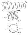
- the stent 10is formed from a resilient wire such as NitinolTM wire or stainless steel and comprises a plurality of struts 12 with a bend 14 between each pair of struts 12. There are seven struts 12 and six bends 14 between them.
- the terminal struts 16 at each endterminate in a loop 18 which comprises at least one turn of the resilient wire and preferably one and a quarter turns. The use of the loops 18 prevents sharp ends from the wire stent from digging into the vasculature into which a stent graft, incorporating the self expanding stent, is deployed.
- the struts, bends and loopsare in a single plane and when they are to be used they are formed into a cylindrical or polygonal body 20 as shown in Figure 2 .
- the terminal struts 16overlap each other to give in effect an at least one strut overlap.
- the terminal loops 18are positioned at the opposite ends of the cylindrical or polygonal body 20.
- FIG. 1 to 3has seven struts 12 and six bends 14 between them and hence when formed into cylindrical or polygonal body 20 has a plan view in the shape of a hexagon as can be seen in Figure 3 .
- the stentWhen assembled onto a stent graft the stent is maintained into its cylindrical or polygonal body form by being stitched to the tubular body of the graft material.
- NitinolTMis a shape memory metal formed from a nickel-titanium (NiTi) alloy that "remembers" its geometry. The wire is formed into the desired zig-zag shape and then heat treated to retain that shape. After cooling, if it is deformed, it will return to the desired zig-zag shape.
- NiTinickel-titanium
- the stent 30is formed from a resilient wire such as NitinolTM wire or stainless steel and comprises a zig-zag structure formed from a plurality of struts 32 with a bends 34 and 35 between each pair of struts 32.
- a resilient wiresuch as NitinolTM wire or stainless steel
- the terminal struts 36 at each endterminate in a loop 38 which comprises at least one turn of the resilient wire and preferably one and a quarter or more turns.
- the use of the loops 38prevents sharp ends from the wire stent from digging into the vasculature into which a stent graft, incorporating the self expanding stent of the present invention, is deployed.
- the stentis comprised of struts, bends and loops is in a single plane and when it is to be used it is formed into a cylindrical or polygonal body 40 as shown in Figure 5 .
- the strutsare overlapped with each other to give a two strut overlap.
- the terminal loops 38are positioned at the same end of the cylindrical or polygonal body 20.
- Figure 5also shows that when the stent is formed into the substantially cylindrical shape then the bends 34 define a first circular shape shown by dotted line 37 and the bends 35 define a second circular shape shown by dotted line 39.
- the stent 30 shown in Figures 4 to 6has twelve struts 32 and six bends 34, 35 between them and hence when formed into cylindrical or polygonal body 40 with an overlap of two struts has a plan view in the shape of a decagon as can be seen in Figure 3 .
- the stentWhen assembled onto a stent graft the stent is maintained into its cylindrical or polygonal body form by being stitched to the tubular body of the graft material.
- connection socket of a stent graftmay be for a side arm for a stent graft adapted for deployment into the common iliac artery or may be for a terminal end of a leg of a bifurcated stent graft such as a for a stent graft adapted to be deployed into the aortic bifurcation.
- the tube 50may be a side arm for a stent graft or may be a terminal end of a leg of a bifurcated graft.
- the tube 50has a socket arrangement 52 into which may be placed a self-expanding stent, a balloon expandable stent or a composite stent or leg extension.
- the tube 50has a first ring 54 stitched to its terminal end and a second ring 56 spaced apart from the first ring 54.
- Each ring 54 and 56is formed from at least two turns and preferably three turns of a nitinol wire and the ends of the nitinol wire terminate in loops 58.
- the use of the loops 58prevents sharp ends from the NitinolTM wire from digging into the vasculature into which the stent graft is deployed.
- the stent 60is formed from a resilient wire such as nitinol wire or stainless steel and comprises a plurality of struts 62 with bends 64 between a pair of struts 62.
- the terminal struts 66 at each endterminate in a loop 68 which comprises at least one turn of the resilient wire and preferably one and a quarter turns.
- Stitching 70is used to both hold the stent onto the tubular body 50 as well as to maintain the stent in its cylindrical or polygonal form.
- the resilient stent 60 when stitched in its cylindrical or polygonal formis made to be of a size which is at rest slightly smaller than the diameter of the tube 50 and hence when sewn on to the outside of the tube 50 using stitching 70 it provides a diameter reducing effect on the tube 50.
- the rings 54 and 56provide firm locking for the balloon expanded covered stent and the resilient stent 60, which is expanded by the balloon expanded stent while it is being balloon expanded, provides a compressive effect to keep tension on the balloon expanded stent.
- a firm connection and an improved sealcan be obtained between a stent leg or arm and a bridging stent.
- a similar gripping effectcan be obtained with the use of a self-expanding stent, a composite stent or other form of leg extension incorporating a stent according to the present invention.
- the side tubemay have a diameter of 8 mm and hence a circumference of 26 mm.
- Each of the ringsmay have a diameter at rest of 7 mm and the resilient stent 60 when formed into its cylindrical or polygonal form may have a diameter at rest of 6 mm.
- the first and second ringsmay be spaced apart by 10 mm and the length of the resilient stent 60 may be 6 mm. Hence there may be a gap between the rings and the resilient stent of 2 mm.
- the side armmay have a diameter of 8 mm and a length after the join to a main stent graft of up to 25 mm. It will be realised that for stent grafts to be deployed into the ascending or descending aorta with side arms to extend into their respective branch vessels other lengths and diameters will be applicable.
- Figure 8shows a side branch stent graft or prosthesis of the type adapted for deployment into the iliac arteries, for instance, such that a bridging stent can extend from the side arm into the internal iliac or hypogastric artery.
- the stent graft 71has a main tubular body 72 and a side arm 74. Both the main tubular body and the side arm are formed from a seamless tube of a biocompatible graft material such as Dacron. A triangular aperture is formed in the main tube and a bevel cut into the inner end of the side arm and the side arm stitched into the triangular aperture with stitching 78.
- the side armhas a connection socket arrangement 76 at its distal end 77.
- the connection socket arrangement 76comprises a first ring 79 stitched to its terminal or distal end 77 and a second ring 80 spaced apart from the first ring 79.
- Each ring 79 and 80is formed from at least two turns and preferably three turns of nitinol wire and the ends of the nitinol wire terminate in loops 81.
- the use of the loops 81prevent sharp ends from the nitinol wire from digging into the vasculature into which the stent graft is deployed.
- the stent 82is formed from a resilient wire such as nitinol wire or stainless steel and comprises a plurality of struts with bends between a pair of struts. In this embodiment there are seven struts and six bends between them.
- the terminal struts at each endterminate in a loop 85 which comprises at least one turn of the resilient wire and preferably one and a quarter turns. Stitching is used to both hold the stent onto the tubular body as well as to maintain the stent in its cylindrical or polygonal form.
- a bridging stentsuch as a balloon expandable stent
- the rings 79 and 80provide firm locking for the balloon expanded stent and the resilient stent 82 which is expanded by the balloon expanded stent while it is being balloon expanded provides a compressive effect to keep tension on the balloon expanded stent.
- a firm connection and an improved sealcan be obtained between the side arm and a bridging stent.
- a similar gripping effectcan be obtained with the use of a bridging stent in the form of a self-expanding stent, a composite stent or other form of leg extension.
Landscapes
- Health & Medical Sciences (AREA)
- Engineering & Computer Science (AREA)
- Biomedical Technology (AREA)
- Heart & Thoracic Surgery (AREA)
- Public Health (AREA)
- Transplantation (AREA)
- Cardiology (AREA)
- Veterinary Medicine (AREA)
- Oral & Maxillofacial Surgery (AREA)
- Vascular Medicine (AREA)
- Life Sciences & Earth Sciences (AREA)
- Animal Behavior & Ethology (AREA)
- General Health & Medical Sciences (AREA)
- Gastroenterology & Hepatology (AREA)
- Pulmonology (AREA)
- Prostheses (AREA)
- Media Introduction/Drainage Providing Device (AREA)
Description
- This invention relates to a stent graft including a self expanding stent.
- Self expanding stents are used either bare or in conjunction with a biocompatible graft material in endovascular therapies in which the stent is placed in a body lumen to reinforce the lumen or a tubular graft placed into the lumen.
- Self expanding stents are generally formed from a resilient wire such as Nitinol™ or stainless steel and made in a zig-zag form with the ends joined to form a cylindrical or polygonal body. The cylindrical or polygonal body can be reduced in diameter by compressing the stent against its resilient forces to permit placement by endovascular techniques and then released to expand in a desired position in the vasculature. The joining of the ends of the resilient wire can be a problem because joining requires welding or soldering and the heating involved can induce brittleness around the joint.
- Nitinol™ in particular, is difficult to join and the region around the joint may need to be annealed which could remove the resilient nature of the material. This invention proposes an alternative method of forming self expanding stents and a stent so formed or at least provides a practitioner with a useful alternative.
- Throughout this specification the term distal with respect to a portion of the aorta, a deployment device or a prosthesis is the end of the aorta, deployment device or prosthesis further away in the direction of blood flow away from the heart and the term proximal means the portion of the aorta, deployment device or end of the prosthesis nearer to the heart. When applied to other vessels similar terms such as caudal and cranial should be understood.
- According to the invention, there is provided a stent graft according to the appended claims.
- Thus the stent is retained in a cylindrical (or polygonal) form without the need for welding or soldering the ends of the wire.
- Preferably the self expanding stent comprises a first loop of the resilient wire at the terminal end of the first strut and a second loop of the resilient wire at the terminal end of the final strut. The loops preferably comprise at least one and a quarter turns of the resilient wire.
- There may be an odd number of struts such as the stent comprising seven struts and six bends. In this case, the terminal loops are positioned at opposite ends of the cylindrical or polygonal body.
- Alternatively there can be an even number of struts and at least two struts overlapping when the stent is formed into the substantially cylindrical form. In this case, the terminal loops are positioned at the same end of the cylindrical or polygonal body.
- The resilient wire can be selected from the group comprising Nitinol™, stainless steel, cobalt alloys and titanium alloys.
- The stent is formed into its cylindrical form by being stitched onto a tubular body of a biocompatible graft material with at least the first strut and the last strut overlapping.
- It will be seen that by this invention there is provided a self expanding stent that is mounted onto a tubular body of graft material and is made into the desirable cylindrical form but does not have any welded joint which reduces the chance of fracture caused by embrittlement which may occur during welding or soldering. This is particularly desirable for Nitinol™ wire. A stent-graft according to the preamble of claim 1 is known from document
EP-A-0997115 . - Preferred embodiments of the invention will now be described by way of example only and with reference to the accompanying drawings in which:
Figure 1 shows one form of stent;Figure 2 shows a perspective view the embodiment ofFigure 1 formed into a cylindrical self expanding stent;Figure 3 shows a plan view ofFigure 2 ;Figure 4 shows an alternative form of stent;Figure 5 shows a perspective view ofFigure 4 formed into a cylindrical self expanding stent;Figure 6 shows a plan view ofFigure 4 ;Figure 7 shows a connection socket; andFigure 8 shows a side branch stent graft or prosthesis of the type adapted for deployment into the iliac arteries and including a connection socket having a stent according to an aspect of this invention.- In
Figures 1 to 3 , thestent 10 is formed from a resilient wire such as Nitinol™ wire or stainless steel and comprises a plurality ofstruts 12 with abend 14 between each pair ofstruts 12. There are sevenstruts 12 and sixbends 14 between them. The terminal struts 16 at each end terminate in aloop 18 which comprises at least one turn of the resilient wire and preferably one and a quarter turns. The use of theloops 18 prevents sharp ends from the wire stent from digging into the vasculature into which a stent graft, incorporating the self expanding stent, is deployed. As formed, the struts, bends and loops are in a single plane and when they are to be used they are formed into a cylindrical orpolygonal body 20 as shown inFigure 2 . In the cylindrical form the terminal struts 16 overlap each other to give in effect an at least one strut overlap. When there are an odd number of struts then theterminal loops 18 are positioned at the opposite ends of the cylindrical orpolygonal body 20. - The example shown in
Figures 1 to 3 has sevenstruts 12 and sixbends 14 between them and hence when formed into cylindrical orpolygonal body 20 has a plan view in the shape of a hexagon as can be seen inFigure 3 . - When assembled onto a stent graft the stent is maintained into its cylindrical or polygonal body form by being stitched to the tubular body of the graft material.
- Nitinol™ is a shape memory metal formed from a nickel-titanium (NiTi) alloy that "remembers" its geometry. The wire is formed into the desired zig-zag shape and then heat treated to retain that shape. After cooling, if it is deformed, it will return to the desired zig-zag shape.
- Now looking at the example shown in
Figures 4 to 6 , thestent 30 is formed from a resilient wire such as Nitinol™ wire or stainless steel and comprises a zig-zag structure formed from a plurality ofstruts 32 with abends struts 32. In this embodiment there are twelvestruts 32, five bends 34 at one side of the zig-zag structure and sixbends 35 at the other side of the zig-zag structure between them. The terminal struts 36 at each end terminate in aloop 38 which comprises at least one turn of the resilient wire and preferably one and a quarter or more turns. The use of theloops 38 prevents sharp ends from the wire stent from digging into the vasculature into which a stent graft, incorporating the self expanding stent of the present invention, is deployed. As formed the stent is comprised of struts, bends and loops is in a single plane and when it is to be used it is formed into a cylindrical orpolygonal body 40 as shown inFigure 5 . In the cylindrical form the struts are overlapped with each other to give a two strut overlap. As there is an even number of struts then theterminal loops 38 are positioned at the same end of the cylindrical orpolygonal body 20.Figure 5 also shows that when the stent is formed into the substantially cylindrical shape then thebends 34 define a first circular shape shown by dottedline 37 and thebends 35 define a second circular shape shown by dottedline 39. - The
stent 30 shown inFigures 4 to 6 has twelvestruts 32 and sixbends polygonal body 40 with an overlap of two struts has a plan view in the shape of a decagon as can be seen inFigure 3 . - When assembled onto a stent graft the stent is maintained into its cylindrical or polygonal body form by being stitched to the tubular body of the graft material.
Figure 7 shows a connection socket of a stent graft according to the present invention. The connection socket may be for a side arm for a stent graft adapted for deployment into the common iliac artery or may be for a terminal end of a leg of a bifurcated stent graft such as a for a stent graft adapted to be deployed into the aortic bifurcation.- In this embodiment the
tube 50 may be a side arm for a stent graft or may be a terminal end of a leg of a bifurcated graft. Thetube 50 has asocket arrangement 52 into which may be placed a self-expanding stent, a balloon expandable stent or a composite stent or leg extension. Thetube 50 has afirst ring 54 stitched to its terminal end and asecond ring 56 spaced apart from thefirst ring 54. Eachring loops 58. The use of theloops 58 prevents sharp ends from the Nitinol™ wire from digging into the vasculature into which the stent graft is deployed. - Between the
first ring 54 and thesecond ring 56 is astent 60 according to the present invention formed from a resilient material. Thestent 60 is formed from a resilient wire such as nitinol wire or stainless steel and comprises a plurality ofstruts 62 withbends 64 between a pair ofstruts 62. The terminal struts 66 at each end terminate in aloop 68 which comprises at least one turn of the resilient wire and preferably one and a quarter turns.Stitching 70 is used to both hold the stent onto thetubular body 50 as well as to maintain the stent in its cylindrical or polygonal form. - The
resilient stent 60 when stitched in its cylindrical or polygonal form is made to be of a size which is at rest slightly smaller than the diameter of thetube 50 and hence when sewn on to the outside of thetube 50 usingstitching 70 it provides a diameter reducing effect on thetube 50. - When a balloon expandable stent or balloon expanded covered stent is placed into the
socket 52 and expanded, therings resilient stent 60, which is expanded by the balloon expanded stent while it is being balloon expanded, provides a compressive effect to keep tension on the balloon expanded stent. By this means a firm connection and an improved seal can be obtained between a stent leg or arm and a bridging stent. A similar gripping effect can be obtained with the use of a self-expanding stent, a composite stent or other form of leg extension incorporating a stent according to the present invention. - In one particular embodiment the side tube may have a diameter of 8 mm and hence a circumference of 26 mm. Each of the rings may have a diameter at rest of 7 mm and the
resilient stent 60 when formed into its cylindrical or polygonal form may have a diameter at rest of 6 mm. The first and second rings may be spaced apart by 10 mm and the length of theresilient stent 60 may be 6 mm. Hence there may be a gap between the rings and the resilient stent of 2 mm. - In the case of a stent graft to be deployed into the common iliac artery with the side arm adapted to extend towards the internal iliac artery the side arm may have a diameter of 8 mm and a length after the join to a main stent graft of up to 25 mm. It will be realised that for stent grafts to be deployed into the ascending or descending aorta with side arms to extend into their respective branch vessels other lengths and diameters will be applicable.
Figure 8 shows a side branch stent graft or prosthesis of the type adapted for deployment into the iliac arteries, for instance, such that a bridging stent can extend from the side arm into the internal iliac or hypogastric artery.- The
stent graft 71 has a maintubular body 72 and aside arm 74. Both the main tubular body and the side arm are formed from a seamless tube of a biocompatible graft material such as Dacron. A triangular aperture is formed in the main tube and a bevel cut into the inner end of the side arm and the side arm stitched into the triangular aperture withstitching 78. The side arm has aconnection socket arrangement 76 at itsdistal end 77. Theconnection socket arrangement 76 comprises afirst ring 79 stitched to its terminal ordistal end 77 and asecond ring 80 spaced apart from thefirst ring 79. Eachring - Between the
first ring 79 and thesecond ring 80 is astent 82 according to the present invention formed from a resilient material. Thestent 82 is formed from a resilient wire such as nitinol wire or stainless steel and comprises a plurality of struts with bends between a pair of struts. In this embodiment there are seven struts and six bends between them. The terminal struts at each end terminate in aloop 85 which comprises at least one turn of the resilient wire and preferably one and a quarter turns. Stitching is used to both hold the stent onto the tubular body as well as to maintain the stent in its cylindrical or polygonal form. - When a bridging stent such as a balloon expandable stent is placed into the
socket 77 and expanded, therings resilient stent 82 which is expanded by the balloon expanded stent while it is being balloon expanded provides a compressive effect to keep tension on the balloon expanded stent. By this means a firm connection and an improved seal can be obtained between the side arm and a bridging stent. A similar gripping effect can be obtained with the use of a bridging stent in the form of a self-expanding stent, a composite stent or other form of leg extension.
Claims (12)
- A stent graft including a self-expanding stent (10, 30, 60, 82), the stent comprising a resilient wire, the resilient wire comprising a plurality of struts (12, 32, 62) and a bend (14, 34, 35, 64) between each strut, the stent as formed being substantially planar,characterised in that the stent in use is formed into a substantially cylindrical or polygonal form (20, 40) with at least the first strut and the last strut overlapping and contacting each other, the stent thereby being retained in said substantially cylindrical or polygonal formin situ by being stitched onto a tubular body (50) of graft material thus avoiding the need of a welded joint.
- A stent graft (10, 30, 60, 82) as claimed in claim 1, wherein the self-expanding stent comprises a first loop (18, 38) of the resilient wire at the terminal end of the first strut (16, 36, 66) and a second loop (18, 68) of the resilient wire at the terminal end of the last strut (16, 36, 66).
- A stent graft (10, 30, 60, 82) as claimed in claim 2, wherein the loops (18, 38, 85) comprise at least one and a quarter turns of the resilient wire.
- A stent graft (10, 30, 60, 82) as claimed in claim 1, 2 or 3, wherein there are an odd number of struts (12, 32, 62).
- A stent graft (10, 30, 60, 82) as claimed in claim 4, comprising seven struts (12, 32, 62) and six bends (14, 34, 35, 64).
- A stent graft (10, 30, 60, 82) as claimed in claim 1, 2 or 3, wherein there are an even number of struts (12, 32, 62) and at least two struts overlapping when the stent is formed into the substantially cylindrical form (20, 40).
- A stent graft (10, 30, 60, 82) as claimed in any preceding claim, wherein the resilient wire is selected from the group comprising Nitinol™, stainless steel, cobalt alloys and titanium alloys.
- A stent graft (10, 30, 60, 82) as claimed in claim 1, wherein the resilient wire comprises a zig-zag form, a first loop (18, 38) of the resilient wire at the terminal end of the first strut (16, 36, 66) and a second loop (18, 38) of the resilient wire at the terminal end of the last strut (16, 36, 66).
- A stent graft (10, 30, 60, 82) as claimed in claim 8, wherein the resilient wire is Nitinol™ and includes seven struts.
- A connection socket (52, 76) for a stent graft, including a stent graft as claimed in any preceding claim.
- A connection socket (52, 76) as claimed in claim 10, wherein the self-expanding stent is of a size which is, at rest, smaller than the diameter of the tubular body (50).
- A connection socket (52, 76) as claimed in claim 10 or 11, including a first ring (54) stitched to its terminal end, and a second ring (56) spaced apart from the first ring.
Applications Claiming Priority (2)
| Application Number | Priority Date | Filing Date | Title |
|---|---|---|---|
| US75985106P | 2006-01-18 | 2006-01-18 | |
| PCT/US2007/001195WO2007084537A2 (en) | 2006-01-18 | 2007-01-17 | Self expanding stent |
Publications (2)
| Publication Number | Publication Date |
|---|---|
| EP1973501A2 EP1973501A2 (en) | 2008-10-01 |
| EP1973501B1true EP1973501B1 (en) | 2013-10-16 |
Family
ID=38006776
Family Applications (1)
| Application Number | Title | Priority Date | Filing Date |
|---|---|---|---|
| EP07716704.7AActiveEP1973501B1 (en) | 2006-01-18 | 2007-01-17 | Self expanding stent |
Country Status (4)
| Country | Link |
|---|---|
| US (2) | US8840657B2 (en) |
| EP (1) | EP1973501B1 (en) |
| AU (1) | AU2007207602B2 (en) |
| WO (1) | WO2007084537A2 (en) |
Families Citing this family (29)
| Publication number | Priority date | Publication date | Assignee | Title |
|---|---|---|---|---|
| US7147661B2 (en) | 2001-12-20 | 2006-12-12 | Boston Scientific Santa Rosa Corp. | Radially expandable stent |
| EP3103422A1 (en)* | 2003-03-14 | 2016-12-14 | Intersect ENT, Inc. | Sinus delivery of sustained release therapeutics |
| JP5247428B2 (en) | 2005-04-04 | 2013-07-24 | インターセクト エント, インコーポレイテッド | Apparatus and method for treating sinus symptoms |
| US8535707B2 (en) | 2006-07-10 | 2013-09-17 | Intersect Ent, Inc. | Devices and methods for delivering active agents to the osteomeatal complex |
| US20080300671A1 (en)* | 2007-06-04 | 2008-12-04 | Gil Vardi | Stent having high expansion ratio |
| EP3791826B1 (en) | 2007-12-18 | 2025-01-29 | Intersect ENT, Inc. | Self-expanding devices |
| KR100943255B1 (en)* | 2008-07-21 | 2010-02-19 | (주) 태웅메디칼 | Stent |
| AU2009276505B2 (en) | 2008-08-01 | 2015-04-23 | Intersect Ent, Inc. | Methods and devices for crimping self-expanding devices |
| EP2754463B1 (en) | 2009-05-15 | 2016-06-22 | Intersect ENT, Inc. | Expandable devices |
| US8741660B2 (en)* | 2009-05-19 | 2014-06-03 | Stokes Bio Limited | Sampling device |
| AU2009202301B8 (en) | 2009-06-10 | 2009-12-03 | Cook Incorporated | Reinforcing ring |
| US9265599B2 (en)* | 2011-08-31 | 2016-02-23 | Cleveland Clinic Foundation | Retention system for an endoluminal device |
| US10561509B2 (en) | 2013-03-13 | 2020-02-18 | DePuy Synthes Products, Inc. | Braided stent with expansion ring and method of delivery |
| AU2014236729B2 (en) | 2013-03-14 | 2018-11-22 | Intersect Ent, Inc. | Systems, devices, and method for treating a sinus condition |
| CN104116577B (en)* | 2014-06-27 | 2017-07-14 | 先健科技(深圳)有限公司 | Branch type overlay film frame |
| US10206796B2 (en) | 2014-08-27 | 2019-02-19 | DePuy Synthes Products, Inc. | Multi-strand implant with enhanced radiopacity |
| WO2016090112A1 (en) | 2014-12-04 | 2016-06-09 | Trivascular, Inc. | Internal iliac preservation devices and methods |
| JP2018504209A (en) | 2015-01-22 | 2018-02-15 | インターセクト エント, インコーポレイテッド | Drug coated balloon |
| US10076428B2 (en) | 2016-08-25 | 2018-09-18 | DePuy Synthes Products, Inc. | Expansion ring for a braided stent |
| US10292851B2 (en) | 2016-09-30 | 2019-05-21 | DePuy Synthes Products, Inc. | Self-expanding device delivery apparatus with dual function bump |
| US11523920B2 (en) | 2017-03-16 | 2022-12-13 | Keyvon Rashidi | Stent with a smooth surface in its expanded configuration |
| AU2019204522A1 (en) | 2018-07-30 | 2020-02-13 | DePuy Synthes Products, Inc. | Systems and methods of manufacturing and using an expansion ring |
| US10456280B1 (en) | 2018-08-06 | 2019-10-29 | DePuy Synthes Products, Inc. | Systems and methods of using a braided implant |
| US10278848B1 (en) | 2018-08-06 | 2019-05-07 | DePuy Synthes Products, Inc. | Stent delivery with expansion assisting delivery wire |
| US11039944B2 (en) | 2018-12-27 | 2021-06-22 | DePuy Synthes Products, Inc. | Braided stent system with one or more expansion rings |
| US20220211524A1 (en)* | 2019-03-28 | 2022-07-07 | Jms Co., Ltd. | Synthetic resin stent and stent delivery system |
| WO2020236834A1 (en)* | 2019-05-20 | 2020-11-26 | Seshadri Raju | Modified z stents for iliac vein stenting |
| US12403291B2 (en) | 2019-08-30 | 2025-09-02 | Intersect Ent, Inc. | Submucosal bioresorbable drug eluting platform |
| KR102486166B1 (en)* | 2022-07-04 | 2023-01-09 | 주식회사 제가텍 | Stent, Method and Pin-combined Jig for Forming the Same |
Family Cites Families (25)
| Publication number | Priority date | Publication date | Assignee | Title |
|---|---|---|---|---|
| US4800882A (en) | 1987-03-13 | 1989-01-31 | Cook Incorporated | Endovascular stent and delivery system |
| US5133732A (en) | 1987-10-19 | 1992-07-28 | Medtronic, Inc. | Intravascular stent |
| US5035706A (en)* | 1989-10-17 | 1991-07-30 | Cook Incorporated | Percutaneous stent and method for retrieval thereof |
| EP0545091B1 (en)* | 1991-11-05 | 1999-07-07 | The Children's Medical Center Corporation | Occluder for repair of cardiac and vascular defects |
| CA2157575C (en) | 1994-04-01 | 2000-03-07 | Lilip Lau | Self-expandable stent and stent-graft and method of using them |
| US6352561B1 (en)* | 1996-12-23 | 2002-03-05 | W. L. Gore & Associates | Implant deployment apparatus |
| US5733330A (en)* | 1997-01-13 | 1998-03-31 | Advanced Cardiovascular Systems, Inc. | Balloon-expandable, crush-resistant locking stent |
| US7452371B2 (en)* | 1999-06-02 | 2008-11-18 | Cook Incorporated | Implantable vascular device |
| EP1087727B1 (en)* | 1998-06-02 | 2004-11-10 | Cook Incorporated | Multiple-sided intraluminal medical device |
| US6656218B1 (en)* | 1998-07-24 | 2003-12-02 | Micrus Corporation | Intravascular flow modifier and reinforcement device |
| US6733523B2 (en)* | 1998-12-11 | 2004-05-11 | Endologix, Inc. | Implantable vascular graft |
| US7628803B2 (en)* | 2001-02-05 | 2009-12-08 | Cook Incorporated | Implantable vascular device |
| EP1487380B1 (en)* | 2002-03-25 | 2008-02-27 | Cook Incorporated | Branched vessel prothesis |
| US20040117004A1 (en)* | 2002-05-16 | 2004-06-17 | Osborne Thomas A. | Stent and method of forming a stent with integral barbs |
| ATE377398T1 (en)* | 2002-11-22 | 2007-11-15 | Cook Inc | STENT VESSEL TRANSPLANT |
| US7846198B2 (en)* | 2002-12-24 | 2010-12-07 | Novostent Corporation | Vascular prosthesis and methods of use |
| US6966923B2 (en)* | 2003-01-24 | 2005-11-22 | Medtronic Vascular, Inc. | Stent delivery system and low profile stent |
| WO2004075789A2 (en)* | 2003-02-26 | 2004-09-10 | Cook Incorporated | PROTHESIS ADAPTED FOR PLACEDd UNDER EXTERNAL IMAGING |
| EP3424463A1 (en)* | 2003-11-08 | 2019-01-09 | Cook Medical Technologies LLC | Aorta and branch vessel stent grafts and system |
| JP4464972B2 (en)* | 2003-12-17 | 2010-05-19 | クック・インコーポレイテッド | Interconnected leg extensions for endoluminal prostheses |
| AU2005206200B2 (en)* | 2004-01-20 | 2010-12-09 | Cook Medical Technologies Llc | Multiple stitches for attaching stent to graft |
| AU2005286843B2 (en)* | 2004-09-21 | 2011-07-14 | Cook Incorporated | Side branch stent graft |
| DE602005023033D1 (en)* | 2004-09-21 | 2010-09-30 | Cook Inc | STENT GRAFT CONNECTION ARRANGEMENT |
| US8864819B2 (en)* | 2004-12-17 | 2014-10-21 | Cook Medical Technologies Llc | Stented side branch graft |
| US7399314B2 (en)* | 2005-11-15 | 2008-07-15 | Cordis Corporation | Systems and methods for securing graft material to intraluminal devices |
- 2007
- 2007-01-17WOPCT/US2007/001195patent/WO2007084537A2/enactiveApplication Filing
- 2007-01-17EPEP07716704.7Apatent/EP1973501B1/enactiveActive
- 2007-01-17USUS11/654,423patent/US8840657B2/enactiveActive
- 2007-01-17AUAU2007207602Apatent/AU2007207602B2/enactiveActive
- 2014
- 2014-08-21USUS14/465,073patent/US20170258610A9/ennot_activeAbandoned
Also Published As
| Publication number | Publication date |
|---|---|
| EP1973501A2 (en) | 2008-10-01 |
| WO2007084537A3 (en) | 2007-09-07 |
| AU2007207602B2 (en) | 2012-08-23 |
| US20170258610A9 (en) | 2017-09-14 |
| WO2007084537A2 (en) | 2007-07-26 |
| US20070191922A1 (en) | 2007-08-16 |
| AU2007207602A1 (en) | 2007-07-26 |
| US20140364936A1 (en) | 2014-12-11 |
| US8840657B2 (en) | 2014-09-23 |
Similar Documents
| Publication | Publication Date | Title |
|---|---|---|
| EP1973501B1 (en) | Self expanding stent | |
| US11771573B2 (en) | Side branch stent graft | |
| US9237959B2 (en) | Stent and barb | |
| US9775731B2 (en) | Ring stent | |
| US20210093472A1 (en) | Stent attachment and deployment mechanism | |
| US9848977B2 (en) | Aortic graft device | |
| US6860900B2 (en) | Stent and stent-graft for treating branched vessels | |
| EP2055264B1 (en) | Percutaneous endoprosthesis using suprarenal fixation and barbed anchors | |
| US7025779B2 (en) | Endoluminal device having enhanced affixation characteristics | |
| US8177833B2 (en) | System and method for forming a junction between elements of a modular endovascular prosthesis | |
| US20050033406A1 (en) | Branch vessel stent and graft | |
| EP2074968A1 (en) | Endoprosthesis for vascular bifurcation | |
| EP2659860B1 (en) | Stent graft adaptor | |
| JP2003521995A (en) | Stent matrix |
Legal Events
| Date | Code | Title | Description |
|---|---|---|---|
| PUAI | Public reference made under article 153(3) epc to a published international application that has entered the european phase | Free format text:ORIGINAL CODE: 0009012 | |
| 17P | Request for examination filed | Effective date:20080721 | |
| AK | Designated contracting states | Kind code of ref document:A2 Designated state(s):AT BE BG CH CY CZ DE DK EE ES FI FR GB GR HU IE IS IT LI LT LU LV MC NL PL PT RO SE SI SK TR | |
| RAP1 | Party data changed (applicant data changed or rights of an application transferred) | Owner name:WILLIAM A. COOK AUSTRALIA PTY. LTD. Owner name:COOK MEDICAL TECHNOLOGIES LLC | |
| RAP1 | Party data changed (applicant data changed or rights of an application transferred) | Owner name:COOK MEDICAL TECHNOLOGIES LLC Owner name:WILLIAM A. COOK AUSTRALIA PTY. LTD. | |
| DAX | Request for extension of the european patent (deleted) | ||
| GRAP | Despatch of communication of intention to grant a patent | Free format text:ORIGINAL CODE: EPIDOSNIGR1 | |
| GRAP | Despatch of communication of intention to grant a patent | Free format text:ORIGINAL CODE: EPIDOSNIGR1 | |
| INTG | Intention to grant announced | Effective date:20130624 | |
| GRAS | Grant fee paid | Free format text:ORIGINAL CODE: EPIDOSNIGR3 | |
| GRAA | (expected) grant | Free format text:ORIGINAL CODE: 0009210 | |
| AK | Designated contracting states | Kind code of ref document:B1 Designated state(s):AT BE BG CH CY CZ DE DK EE ES FI FR GB GR HU IE IS IT LI LT LU LV MC NL PL PT RO SE SI SK TR | |
| REG | Reference to a national code | Ref country code:GB Ref legal event code:FG4D | |
| REG | Reference to a national code | Ref country code:CH Ref legal event code:EP | |
| REG | Reference to a national code | Ref country code:IE Ref legal event code:FG4D | |
| REG | Reference to a national code | Ref country code:AT Ref legal event code:REF Ref document number:636084 Country of ref document:AT Kind code of ref document:T Effective date:20131115 | |
| REG | Reference to a national code | Ref country code:DE Ref legal event code:R096 Ref document number:602007033342 Country of ref document:DE Effective date:20131212 | |
| REG | Reference to a national code | Ref country code:NL Ref legal event code:VDEP Effective date:20131016 | |
| REG | Reference to a national code | Ref country code:AT Ref legal event code:MK05 Ref document number:636084 Country of ref document:AT Kind code of ref document:T Effective date:20131016 | |
| REG | Reference to a national code | Ref country code:LT Ref legal event code:MG4D | |
| PG25 | Lapsed in a contracting state [announced via postgrant information from national office to epo] | Ref country code:LT Free format text:LAPSE BECAUSE OF FAILURE TO SUBMIT A TRANSLATION OF THE DESCRIPTION OR TO PAY THE FEE WITHIN THE PRESCRIBED TIME-LIMIT Effective date:20131016 Ref country code:FI Free format text:LAPSE BECAUSE OF FAILURE TO SUBMIT A TRANSLATION OF THE DESCRIPTION OR TO PAY THE FEE WITHIN THE PRESCRIBED TIME-LIMIT Effective date:20131016 Ref country code:BE Free format text:LAPSE BECAUSE OF FAILURE TO SUBMIT A TRANSLATION OF THE DESCRIPTION OR TO PAY THE FEE WITHIN THE PRESCRIBED TIME-LIMIT Effective date:20131016 Ref country code:NL Free format text:LAPSE BECAUSE OF FAILURE TO SUBMIT A TRANSLATION OF THE DESCRIPTION OR TO PAY THE FEE WITHIN THE PRESCRIBED TIME-LIMIT Effective date:20131016 Ref country code:IS Free format text:LAPSE BECAUSE OF FAILURE TO SUBMIT A TRANSLATION OF THE DESCRIPTION OR TO PAY THE FEE WITHIN THE PRESCRIBED TIME-LIMIT Effective date:20140216 Ref country code:SE Free format text:LAPSE BECAUSE OF FAILURE TO SUBMIT A TRANSLATION OF THE DESCRIPTION OR TO PAY THE FEE WITHIN THE PRESCRIBED TIME-LIMIT Effective date:20131016 | |
| PG25 | Lapsed in a contracting state [announced via postgrant information from national office to epo] | Ref country code:AT Free format text:LAPSE BECAUSE OF FAILURE TO SUBMIT A TRANSLATION OF THE DESCRIPTION OR TO PAY THE FEE WITHIN THE PRESCRIBED TIME-LIMIT Effective date:20131016 Ref country code:CY Free format text:LAPSE BECAUSE OF FAILURE TO SUBMIT A TRANSLATION OF THE DESCRIPTION OR TO PAY THE FEE WITHIN THE PRESCRIBED TIME-LIMIT Effective date:20131016 Ref country code:ES Free format text:LAPSE BECAUSE OF FAILURE TO SUBMIT A TRANSLATION OF THE DESCRIPTION OR TO PAY THE FEE WITHIN THE PRESCRIBED TIME-LIMIT Effective date:20131016 Ref country code:LV Free format text:LAPSE BECAUSE OF FAILURE TO SUBMIT A TRANSLATION OF THE DESCRIPTION OR TO PAY THE FEE WITHIN THE PRESCRIBED TIME-LIMIT Effective date:20131016 | |
| PG25 | Lapsed in a contracting state [announced via postgrant information from national office to epo] | Ref country code:PT Free format text:LAPSE BECAUSE OF FAILURE TO SUBMIT A TRANSLATION OF THE DESCRIPTION OR TO PAY THE FEE WITHIN THE PRESCRIBED TIME-LIMIT Effective date:20140217 | |
| REG | Reference to a national code | Ref country code:DE Ref legal event code:R097 Ref document number:602007033342 Country of ref document:DE | |
| PG25 | Lapsed in a contracting state [announced via postgrant information from national office to epo] | Ref country code:EE Free format text:LAPSE BECAUSE OF FAILURE TO SUBMIT A TRANSLATION OF THE DESCRIPTION OR TO PAY THE FEE WITHIN THE PRESCRIBED TIME-LIMIT Effective date:20131016 | |
| PLBE | No opposition filed within time limit | Free format text:ORIGINAL CODE: 0009261 | |
| STAA | Information on the status of an ep patent application or granted ep patent | Free format text:STATUS: NO OPPOSITION FILED WITHIN TIME LIMIT | |
| PG25 | Lapsed in a contracting state [announced via postgrant information from national office to epo] | Ref country code:CZ Free format text:LAPSE BECAUSE OF FAILURE TO SUBMIT A TRANSLATION OF THE DESCRIPTION OR TO PAY THE FEE WITHIN THE PRESCRIBED TIME-LIMIT Effective date:20131016 Ref country code:RO Free format text:LAPSE BECAUSE OF FAILURE TO SUBMIT A TRANSLATION OF THE DESCRIPTION OR TO PAY THE FEE WITHIN THE PRESCRIBED TIME-LIMIT Effective date:20131016 Ref country code:IT Free format text:LAPSE BECAUSE OF FAILURE TO SUBMIT A TRANSLATION OF THE DESCRIPTION OR TO PAY THE FEE WITHIN THE PRESCRIBED TIME-LIMIT Effective date:20131016 Ref country code:MC Free format text:LAPSE BECAUSE OF FAILURE TO SUBMIT A TRANSLATION OF THE DESCRIPTION OR TO PAY THE FEE WITHIN THE PRESCRIBED TIME-LIMIT Effective date:20131016 Ref country code:SK Free format text:LAPSE BECAUSE OF FAILURE TO SUBMIT A TRANSLATION OF THE DESCRIPTION OR TO PAY THE FEE WITHIN THE PRESCRIBED TIME-LIMIT Effective date:20131016 Ref country code:PL Free format text:LAPSE BECAUSE OF FAILURE TO SUBMIT A TRANSLATION OF THE DESCRIPTION OR TO PAY THE FEE WITHIN THE PRESCRIBED TIME-LIMIT Effective date:20131016 Ref country code:LU Free format text:LAPSE BECAUSE OF FAILURE TO SUBMIT A TRANSLATION OF THE DESCRIPTION OR TO PAY THE FEE WITHIN THE PRESCRIBED TIME-LIMIT Effective date:20140117 | |
| REG | Reference to a national code | Ref country code:CH Ref legal event code:PL | |
| 26N | No opposition filed | Effective date:20140717 | |
| PG25 | Lapsed in a contracting state [announced via postgrant information from national office to epo] | Ref country code:DK Free format text:LAPSE BECAUSE OF FAILURE TO SUBMIT A TRANSLATION OF THE DESCRIPTION OR TO PAY THE FEE WITHIN THE PRESCRIBED TIME-LIMIT Effective date:20131016 | |
| REG | Reference to a national code | Ref country code:DE Ref legal event code:R097 Ref document number:602007033342 Country of ref document:DE Effective date:20140717 | |
| PG25 | Lapsed in a contracting state [announced via postgrant information from national office to epo] | Ref country code:LI Free format text:LAPSE BECAUSE OF NON-PAYMENT OF DUE FEES Effective date:20140131 Ref country code:CH Free format text:LAPSE BECAUSE OF NON-PAYMENT OF DUE FEES Effective date:20140131 | |
| REG | Reference to a national code | Ref country code:FR Ref legal event code:ST Effective date:20140930 | |
| PG25 | Lapsed in a contracting state [announced via postgrant information from national office to epo] | Ref country code:FR Free format text:LAPSE BECAUSE OF NON-PAYMENT OF DUE FEES Effective date:20140131 | |
| PG25 | Lapsed in a contracting state [announced via postgrant information from national office to epo] | Ref country code:SI Free format text:LAPSE BECAUSE OF FAILURE TO SUBMIT A TRANSLATION OF THE DESCRIPTION OR TO PAY THE FEE WITHIN THE PRESCRIBED TIME-LIMIT Effective date:20131016 | |
| PG25 | Lapsed in a contracting state [announced via postgrant information from national office to epo] | Ref country code:BG Free format text:LAPSE BECAUSE OF FAILURE TO SUBMIT A TRANSLATION OF THE DESCRIPTION OR TO PAY THE FEE WITHIN THE PRESCRIBED TIME-LIMIT Effective date:20131016 | |
| PG25 | Lapsed in a contracting state [announced via postgrant information from national office to epo] | Ref country code:GR Free format text:LAPSE BECAUSE OF FAILURE TO SUBMIT A TRANSLATION OF THE DESCRIPTION OR TO PAY THE FEE WITHIN THE PRESCRIBED TIME-LIMIT Effective date:20140117 | |
| PG25 | Lapsed in a contracting state [announced via postgrant information from national office to epo] | Ref country code:HU Free format text:LAPSE BECAUSE OF FAILURE TO SUBMIT A TRANSLATION OF THE DESCRIPTION OR TO PAY THE FEE WITHIN THE PRESCRIBED TIME-LIMIT; INVALID AB INITIO Effective date:20070117 Ref country code:TR Free format text:LAPSE BECAUSE OF FAILURE TO SUBMIT A TRANSLATION OF THE DESCRIPTION OR TO PAY THE FEE WITHIN THE PRESCRIBED TIME-LIMIT Effective date:20131016 | |
| P01 | Opt-out of the competence of the unified patent court (upc) registered | Effective date:20230602 | |
| REG | Reference to a national code | Ref country code:GB Ref legal event code:732E Free format text:REGISTERED BETWEEN 20240815 AND 20240821 | |
| REG | Reference to a national code | Ref country code:DE Ref legal event code:R081 Ref document number:602007033342 Country of ref document:DE Owner name:COOK MEDICAL TECHNOLOGIES, LLC, BLOOMINGTON, US Free format text:FORMER OWNERS: COOK MEDICAL TECHNOLOGIES LLC, BLOOMINGTON, IND., US; WILLIAM A. COOK AUSTRALIA PTY. LTD., BRISBANE, QUEENSLAND, AU | |
| PGFP | Annual fee paid to national office [announced via postgrant information from national office to epo] | Ref country code:DE Payment date:20250129 Year of fee payment:19 | |
| PGFP | Annual fee paid to national office [announced via postgrant information from national office to epo] | Ref country code:IE Payment date:20250128 Year of fee payment:19 | |
| PGFP | Annual fee paid to national office [announced via postgrant information from national office to epo] | Ref country code:GB Payment date:20250121 Year of fee payment:19 |