EP1972874B1 - Automated substance warehouse - Google Patents
Automated substance warehouseDownload PDFInfo
- Publication number
- EP1972874B1 EP1972874B1EP08004526.3AEP08004526AEP1972874B1EP 1972874 B1EP1972874 B1EP 1972874B1EP 08004526 AEP08004526 AEP 08004526AEP 1972874 B1EP1972874 B1EP 1972874B1
- Authority
- EP
- European Patent Office
- Prior art keywords
- zone
- transport
- storage
- chamber according
- elevator
- Prior art date
- Legal status (The legal status is an assumption and is not a legal conclusion. Google has not performed a legal analysis and makes no representation as to the accuracy of the status listed.)
- Active
Links
Images


Classifications
- F—MECHANICAL ENGINEERING; LIGHTING; HEATING; WEAPONS; BLASTING
- F25—REFRIGERATION OR COOLING; COMBINED HEATING AND REFRIGERATION SYSTEMS; HEAT PUMP SYSTEMS; MANUFACTURE OR STORAGE OF ICE; LIQUEFACTION SOLIDIFICATION OF GASES
- F25D—REFRIGERATORS; COLD ROOMS; ICE-BOXES; COOLING OR FREEZING APPARATUS NOT OTHERWISE PROVIDED FOR
- F25D25/00—Charging, supporting, and discharging the articles to be cooled
- F25D25/04—Charging, supporting, and discharging the articles to be cooled by conveyors
- A—HUMAN NECESSITIES
- A47—FURNITURE; DOMESTIC ARTICLES OR APPLIANCES; COFFEE MILLS; SPICE MILLS; SUCTION CLEANERS IN GENERAL
- A47B—TABLES; DESKS; OFFICE FURNITURE; CABINETS; DRAWERS; GENERAL DETAILS OF FURNITURE
- A47B63/00—Cabinets, racks or shelf units, specially adapted for storing books, documents, forms, or the like
- A47B63/06—Cabinets, racks or shelf units, specially adapted for storing books, documents, forms, or the like with parts, e.g. trays, card containers, movable on pivots or on chains or belts
- F—MECHANICAL ENGINEERING; LIGHTING; HEATING; WEAPONS; BLASTING
- F25—REFRIGERATION OR COOLING; COMBINED HEATING AND REFRIGERATION SYSTEMS; HEAT PUMP SYSTEMS; MANUFACTURE OR STORAGE OF ICE; LIQUEFACTION SOLIDIFICATION OF GASES
- F25D—REFRIGERATORS; COLD ROOMS; ICE-BOXES; COOLING OR FREEZING APPARATUS NOT OTHERWISE PROVIDED FOR
- F25D13/00—Stationary devices, e.g. cold-rooms
- F25D13/06—Stationary devices, e.g. cold-rooms with conveyors carrying articles to be cooled through the cooling space
- F—MECHANICAL ENGINEERING; LIGHTING; HEATING; WEAPONS; BLASTING
- F25—REFRIGERATION OR COOLING; COMBINED HEATING AND REFRIGERATION SYSTEMS; HEAT PUMP SYSTEMS; MANUFACTURE OR STORAGE OF ICE; LIQUEFACTION SOLIDIFICATION OF GASES
- F25D—REFRIGERATORS; COLD ROOMS; ICE-BOXES; COOLING OR FREEZING APPARATUS NOT OTHERWISE PROVIDED FOR
- F25D3/00—Devices using other cold materials; Devices using cold-storage bodies
- F25D3/10—Devices using other cold materials; Devices using cold-storage bodies using liquefied gases, e.g. liquid air
- F25D3/11—Devices using other cold materials; Devices using cold-storage bodies using liquefied gases, e.g. liquid air with conveyors carrying articles to be cooled through the cooling space
- A—HUMAN NECESSITIES
- A47—FURNITURE; DOMESTIC ARTICLES OR APPLIANCES; COFFEE MILLS; SPICE MILLS; SUCTION CLEANERS IN GENERAL
- A47B—TABLES; DESKS; OFFICE FURNITURE; CABINETS; DRAWERS; GENERAL DETAILS OF FURNITURE
- A47B63/00—Cabinets, racks or shelf units, specially adapted for storing books, documents, forms, or the like
- A47B63/06—Cabinets, racks or shelf units, specially adapted for storing books, documents, forms, or the like with parts, e.g. trays, card containers, movable on pivots or on chains or belts
- A47B63/062—Cabinets, racks or shelf units, specially adapted for storing books, documents, forms, or the like with parts, e.g. trays, card containers, movable on pivots or on chains or belts with trays revolving on a vertical axis
- A—HUMAN NECESSITIES
- A47—FURNITURE; DOMESTIC ARTICLES OR APPLIANCES; COFFEE MILLS; SPICE MILLS; SUCTION CLEANERS IN GENERAL
- A47B—TABLES; DESKS; OFFICE FURNITURE; CABINETS; DRAWERS; GENERAL DETAILS OF FURNITURE
- A47B63/00—Cabinets, racks or shelf units, specially adapted for storing books, documents, forms, or the like
- A47B63/06—Cabinets, racks or shelf units, specially adapted for storing books, documents, forms, or the like with parts, e.g. trays, card containers, movable on pivots or on chains or belts
- A47B63/065—Cabinets, racks or shelf units, specially adapted for storing books, documents, forms, or the like with parts, e.g. trays, card containers, movable on pivots or on chains or belts with trays revolving on a horizontal axis
- A—HUMAN NECESSITIES
- A47—FURNITURE; DOMESTIC ARTICLES OR APPLIANCES; COFFEE MILLS; SPICE MILLS; SUCTION CLEANERS IN GENERAL
- A47B—TABLES; DESKS; OFFICE FURNITURE; CABINETS; DRAWERS; GENERAL DETAILS OF FURNITURE
- A47B63/00—Cabinets, racks or shelf units, specially adapted for storing books, documents, forms, or the like
- A47B63/06—Cabinets, racks or shelf units, specially adapted for storing books, documents, forms, or the like with parts, e.g. trays, card containers, movable on pivots or on chains or belts
- A47B63/067—Cabinets, racks or shelf units, specially adapted for storing books, documents, forms, or the like with parts, e.g. trays, card containers, movable on pivots or on chains or belts with a noria lift
- B—PERFORMING OPERATIONS; TRANSPORTING
- B65—CONVEYING; PACKING; STORING; HANDLING THIN OR FILAMENTARY MATERIAL
- B65G—TRANSPORT OR STORAGE DEVICES, e.g. CONVEYORS FOR LOADING OR TIPPING, SHOP CONVEYOR SYSTEMS OR PNEUMATIC TUBE CONVEYORS
- B65G1/00—Storing articles, individually or in orderly arrangement, in warehouses or magazines
- B65G1/02—Storage devices
- B65G1/04—Storage devices mechanical
- B65G1/12—Storage devices mechanical with separate article supports or holders movable in a closed circuit to facilitate insertion or removal of articles the articles being books, documents, forms or the like
- B65G1/127—Storage devices mechanical with separate article supports or holders movable in a closed circuit to facilitate insertion or removal of articles the articles being books, documents, forms or the like the circuit being confined in a vertical plane
- B—PERFORMING OPERATIONS; TRANSPORTING
- B65—CONVEYING; PACKING; STORING; HANDLING THIN OR FILAMENTARY MATERIAL
- B65G—TRANSPORT OR STORAGE DEVICES, e.g. CONVEYORS FOR LOADING OR TIPPING, SHOP CONVEYOR SYSTEMS OR PNEUMATIC TUBE CONVEYORS
- B65G1/00—Storing articles, individually or in orderly arrangement, in warehouses or magazines
- B65G1/02—Storage devices
- B65G1/04—Storage devices mechanical
- B65G1/12—Storage devices mechanical with separate article supports or holders movable in a closed circuit to facilitate insertion or removal of articles the articles being books, documents, forms or the like
- B65G1/133—Storage devices mechanical with separate article supports or holders movable in a closed circuit to facilitate insertion or removal of articles the articles being books, documents, forms or the like the circuit being confined in a horizontal plane
Definitions
- the inventionrelates to a climate chamber according to the preamble of claim 1.
- Known systemsuse a transport robot which is movably arranged in a corridor between shelves with drawers.
- the robotis able to pull out the drawers and remove the contents from them.
- the robotthen moves to a periphery at the end of the aisle.
- the robotmoves only between the shelves when access is made.
- the area of the peripheryhas a higher temperature than the area of the racks.
- a disadvantage of the known systemsis that they are either suitable exclusively for large storage facilities, or that they leave a lot of space unused. Furthermore, in the known arrangements processing devices can not be easily integrated space-saving while maintaining the footprint.
- a vertical transport mechanismis provided with which the objects between the lower - colder zone - and the upper - warmer zone - can be transported.
- the objectsare transported by a horizontal transport mechanism, which is located at least partially in the upper zone, in a horizontal or oblique direction to the lock.
- the vertical transport mechanismis formed by a transport lift or a paternoster system.
- the proposed storage systemis especially suitable for small and medium-sized warehouse sizes as well as storage systems with integrated processing devices.
- good space utilizationas well as simple and cost-effective solutions of the transport mechanisms are of paramount importance.
- the objectis to provide a climatic cabinet, which is particularly suitable for very high temperatures.
- This objectis achieved in that at least one heater is provided in the upper zone, with which at least the upper zone is heated and in the upper zone a higher temperature is generated than in the lower zone.
- a transport mechanismis provided, with which the objects (13) between the upper zone and the lock can be moved back and forth.
- a compact constructionis achieved in that in the storage zone a plurality of horizontally movable carriers are arranged, which carry the storage bins.
- the carriersare displaceable in such a way that the formation of a transport gap for receiving the lift carriage is made possible for each carrier. This can increase the transport capacity in the horizontal direction.
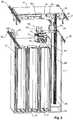
- FIGS. 1 and 2show a first embodiment of a climate cabinet with a lower zone 10 and an upper zone 11.
- the stored materialis stored in the lower zone 10, which forms the storage zone of the device in removable cassettes 12.
- Each cassette 12provides space for receiving a plurality of objects 13 to be stored one above the other.
- the objects 13are preferably so-called microtiter plates.
- the present inventioncan also be used for the storage of other laboratory items, such as bottles, trays, test tube holders, etc.
- the climate chamberforms a cooling trough 14 in which a cooling unit 15 maintains a low temperature. This allows low-temperature storage, while the components in the upper zone 11 are exposed to less low temperatures.
- the upper zone 11is covered by a cover 16 and is also cooled, albeit at a lower temperature.
- a dryer 17is provided, which extracts moisture from the atmosphere in the climatic chamber, in order to avoid icing of the components.
- the dryer 17is a cooling device through which the air is conducted in the climatic chamber and in which the air is brought to a temperature which is lower than the temperature in the other parts of the device. As a result, the air is targeted and deprived of moisture at a defined location.
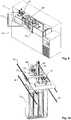
- each support 22can accommodate a plurality, preferably at least three, cassettes 12 in a horizontal direction X side by side, ie each carrier provides space for a variety of storage next to and above each other.
- a plurality of carriers 22are provided, in horizontal Direction Y arranged side by side, wherein the direction Y is perpendicular to the direction X.
- the carriers 22are slidably suspended in the direction Y on guides 35 located opposite one another on a support frame 21 of the upper zone 11.
- the number of carriers 22is selected so that they fill the space available to them in the direction Y up to a transport gap 25.
- the transport gap 25can be formed in front of each of the carriers 22, so that the transport mechanism described later can access the storage locations in the cassettes 12.
- a transport lift 50is suspended.
- the transport lift 50is arranged in the direction Y along the carrier 22 by means of a longitudinal sliding table 31 and in the direction X between the carrier 22 by means of a Querverschiebeticians 41 horizontally movable on the support frame 21.
- the longitudinal displacement table 31is attached to longitudinal guides 32 on the support frame 21 and can be moved with a longitudinal displacement drive 33 in the Y direction.
- the transverse displacement table 41is attached to a transverse guide 42 on the longitudinal displacement table 31 and can be moved with a transverse displacement drive 43 in the direction X.
- the transport lift 50carries a height-movable lifter car 51.
- a turntable 61is arranged, which can be pivoted by a pivot drive 63 about a vertical axis.
- the transport lift 50For access to the stored goods, the transport lift 50 is moved along the carrier 22 to the transport gap 25.
- the lifter car 51can now be moved into the transport gap 25 between the carrier 22 to the desired storage space for the storage object 13.
- the carriersFor the longitudinal process, the carriers have a passage 24 through which the lift column 52 of the transport lift 50 can be moved horizontally in the Y direction.
- the carriers 22are suspended on the guides 35 in the upper zone 11.
- a sliding deviceconsisting of a sliding motor 23 and a slide pinion 23a is provided in the upper zone 11.
- an automatically operable lock(in Fig. 1 and 2 not shown).
- the lockseparates the climate in the interior of the room from the surrounding climate.
- the transport lifttransports the stored goods through the lock.
- a second embodiment of the climatic cabinet(not claimed) is in the FIGS. 3 and 4 represented and uses two carousels 100 for receiving the stored goods.
- the carousels 100are arranged in the lower zone 10.
- the cassettes 12in turn serve to receive the stored goods by providing each cassette 12 with space for several objects 13 one above the other.
- Each turntable 29is suspended on a vertical rotating rod 26 on the support frame 21 of the upper zone 11 and rotatably supported.
- a turntable drive 27 in the upper zone 11each carousel 100 can be rotated relative to the transporting lift 50, so that each cassette 12 can be positioned at the transporting lift 50.
- the transport lift 50is arranged laterally between the carousels 100.
- the transport lift 50is also attached to the support frame 21 in the upper zone 11. It has a vertical drive 53, a pivot drive 63 and a horizontal displacement device, driven by a blade drive 73.
- a lift carriage 51is mounted on a lift column 52 and vertically movable with the vertical drive 53. The travel path of the lift carriage 51 extends from the height of the turntable 29 to over the support frame 21st
- a lock 81is also provided in this climatic cabinet in the upper zone 11 on the vertical side wall, through which the objects 13 can be exchanged with the environment.
- a third embodiment(not claimed) incorporated in the FIGS. 5 and 6 is shown, only one carousel 100 is used by way of example, which in turn is arranged in the lower zone 10.
- a transport lift 50is arranged in the center of rotation of the carousel 100.
- the stored materialis in removable cassettes 12, which are arranged concentrically on the turntable 29 and in a star shape around the transport lift 50 around.
- the transport lift 50has a blade 74, which is pivotable about the carousel axis, parallel to the carousel axis vertically movable and horizontally extendable.
- the blade 74is arranged on the lift carriage 51.
- the transport lift 50rotates with the blade 74 to the cassette 12, in which the desired storage object is located.
- the Liftwagen 51moves to the floor of the cassette with the storage object.
- the blade 74is extended and the object is charged.
- the lift car 51brings the storage object 13 from the lower zone 10 with the cassettes 12 into the upper zone 11, in which the automatically operable lock 81 is located.
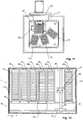
- the stored materialis housed in a paternoster system.
- the paternoster systemconsists of a plurality of paternoster 101, which are arranged in the lower zone 10.
- Each paternoster 101includes a plurality of gondola-type storage tables 103 for the objects 13.
- the storage tables 103are guided to travel along closed transport paths move up and down along the sides of the paternoster, and the paternoster can be moved from one side of the paternoster to the other side of the paternoster at the top and bottom of the paternoster.
- the storage tables 103are only moved in parallel and not tilted.
- each paternoster 101provided on each paternoster 101 a plurality of transport paths for the storage tables 103 in the X direction side by side. In the Y direction several paternoster 101 are arranged side by side.
- the paternoster systemhangs on the support frame 21, which is arranged in the upper zone 11.
- a transport gripper 75is provided in the upper zone 11, which can be moved over each transport path of the paternoster 101.
- the transport gripper 75in the direction of X and Y is moved horizontally.
- the storage table 103is brought to the upper apex position 104 of its transport path and the paternoster 101 is put into operation until the desired storage position is in the apex position 104.
- the transport gripper 75is positioned above the storage table 103, so that the storage object 13 can be picked up from the storage table 103 at the vertex position 104 of the respective paternoster 101 and transported to the lock 81, or vice versa.
- a storage position 85 and a transfer position 86are provided for transport through the lock 81 are in the execution of the FIGS. 7 and 8 .
- the storage position 85is located within the lock 81 and the transfer position 86 outside.
- a processing device 91located.
- Thishas at least one receiving table 92, which one or more the objects 13 can record.
- a processing mechanismis provided (not shown), such as an optical analysis system with which on the objects 13, or the samples therein, on the receiving table 92 manipulations can be made.
- the climatic chamberis subdivided into a lower zone 10 and an upper zone 11, and a cooling unit 15 is provided, which allows a substantially lower temperature to be maintained in the lower zone 10 than in the upper zone 11
- the temperature in the lower zoneis preferably below -30 ° C, especially at about -80 ° C, while in the upper zone preferably more than -30 ° C prevail, eg -20 ° C, so that mechanical components, cable insulation, sensors etc. function without special measures.
- 10 storage bins for storing the objects 13are provided in the lower zone.
- a vertical transport mechanismis provided with which the objects 13 between the lower zone 10 and the upper zone 11 can be moved vertically.
- the vertical transport mechanismis formed by the transport lift 50, according to the embodiment FIGS. 7 and 8 from the paternosters 101.
- the lock 81 and at least part of a horizontal transport mechanismare provided.
- the horizontal transport mechanismmakes it possible to convey the objects 13 in a horizontal or oblique direction between the vertical transport mechanism and the lock 81.
- oblique directionis meant a direction with a horizontal component. If the vertical and horizontal transport mechanism at least partially consist of the same components, it needs no explicit transfer of the object between vertical and horizontal transport mechanism to take place.
- the horizontal transport mechanismis formed by the longitudinal displacement table 31, the longitudinal guide 32, the longitudinal displacement drive 33 and the transverse displacement table 41, the transverse guide 42 and the transverse displacement drive 43; in the execution after FIGS. 3 and 4 from the lift car 51 and the bucket 74; in the execution after FIGS. 5 and 6 also from the lifter carriage 51 and the bucket 74 as well as from the parts 85 and 86 and the transport mechanism arranged therebetween; and in the execution FIGS. 7 and 8 from the transport gripper 75, which can be moved horizontally in the direction X and Y, and from the parts 85 and 86 and the transport mechanism arranged therebetween.
- FIGS. 9 and 10Another embodiment of the invention is disclosed in FIGS. 9 and 10 shown. This corresponds largely to the execution Fig. 1 and 2 , so that only the differences are described below.
- Fig. 9how out Fig. 9 can be seen, in this embodiment in the cover 16 two user doors 110 and 111 are arranged, which provide access to the arranged in the upper zone 11 components.
- User door 110is disposed at a processing device 91. So that the transport lift 50 can bring the objects 13 to the processing device 91 or pick it up from there, it is opposite to the embodiment Fig. 1 and 2 extended upwards.
- an opening 106is provided in the longitudinal displacement table 31 through which the lift column 52 protrudes.
- Fig. 11shows a (not claimed) embodiment of a slightly smaller device with only three stationary cartridges 12. It corresponds approximately to the in Fig. 3 from US 6,478,524
- the climate chamberagain, as in the previous embodiment, is divided into a lower and an upper zone, wherein in the lower Zone is at a lower temperature than in the upper zone.
- the cassettes 12are arranged in the lower zone.
- the lift column 52 of the transport lift 50extends from the lower to the upper zone, so that the lift truck 51 can reciprocate the objects between the two zones.
- the lock 81is, as in the embodiment according to FIGS. 9 and 10 , located in the upper zone, so that an opening of the same does not disturb the temperature equilibrium in the lower zone.
- the same principlecan also be used for climate cabinets, in which the objects 13 are stored at elevated temperature.
- the apparatus shown so faris to be reversed, such that the storage zone is formed by the upper zone 11, while the lock opening 81 comes to lie in the lower zone 10.
- the warm airremains in the storage zone when the lock opening 81 is opened.
- the upper zonecan also be very high temperatures prevail (for example, 100 ° C and more), especially when the guides and bearings of the moving parts are largely arranged in the lower zone 10.
- Fig. 12An example of such a device is in Fig. 12 illustrated. It uses the construction analogous to that of Fig. 10 However, the carriers 22 are arranged in the upper zone 11. The carriers 22 are guided on guides 35 in the lower zone 10 and displaceable in the direction Y. The number of carriers 22 is in turn selected so that they have their available space in the direction Y to to fill in a transport gap 25. By moving individual carriers 22 in the direction Y, the transport gap 25 can be formed in front of each carrier 22, so that the transport mechanism can access the storage locations in the cassettes 12.
- the lift column 52is mounted in this case on a longitudinal guide 32 in the lower zone 10 and projects into the upper zone 11. It carries the transport lift 50 with the rotary carriage 61.
- the transport lift or the lift column 52is in turn horizontally displaceable, in the direction Y as well as in direction X (direction X in FIG Fig. 12 perpendicular to the drawing plane).
- the lift column 52is mounted on a longitudinal displacement table 31, analogous to the embodiment 10.
- a heater 112is mounted at least in the upper zone.
- Reference numeral Directory 10Lower zone 73 bucket drive 11 Upper zone 74 shovel 12 cassette 75 transport gripper 13 object 81 lock 14 cooling trough 82 lock door 15 refrigeration unit 85 storage position 16 cover 86 transfer position 17 dryers 91 processing device 20 object storage 92 shooting table 21 supporting frame 100 carousel 22 carriers 101 paternoster 23 sliding motor 102 conveyor belt 23a slide pinion 103 storage tables 24 gear 104 vertex position 25 transport gap 106 opening 26 turning bar 110, 111 user door 27 turntable drive 112 heating 28 turntable suspension 29 turntable 30 paternoster 31 longitudinal displacement table 32 longitudinal guide 33 longitudinal displacement drive 41 transverse shift table 42 transverse guide 43 transverse displacement drive 50 transport lift 51 lifter cars 52 lift column 53 vertical drive 61 cars 63 Swivel drive 72 bucket guide
Landscapes
- Engineering & Computer Science (AREA)
- Chemical & Material Sciences (AREA)
- Combustion & Propulsion (AREA)
- Physics & Mathematics (AREA)
- Mechanical Engineering (AREA)
- Thermal Sciences (AREA)
- General Engineering & Computer Science (AREA)
- Warehouses Or Storage Devices (AREA)
Description
Translated fromGermanDie Erfindung bezieht sich auf einen Klimaschrank gemäss Oberbegriff von Anspruch 1.The invention relates to a climate chamber according to the preamble of
Mit steigendem Automatisierungsgrad in der Medizinaltechnik steigt das Bedürfnis, Substanzen aus einem Langzeitlager automatisch bewirtschaften zu können. Zur Vermeidung chemischer Veränderungen der Substanzen werden diese vielfach bei möglichst tiefen Temperaturen gelagert. Hierbei kommen den Temperaturbereichen unter -80°C eine steigende Bedeutung zu. Der Transport von Lagergut bei diesen Tiefsttemperaturen stellt besondere Anforderungen an die Mechanik und Steuerung eines Lagersystems.As the level of automation in medical technology increases, so does the need to be able to automatically process substances from a long-term storage facility. To avoid chemical changes of the substances, these are often stored at the lowest possible temperatures. In this case, the temperature ranges below -80 ° C are becoming increasingly important. The transport of stored goods at these lowest temperatures places special demands on the mechanics and control of a storage system.
Bekannte Systeme verwenden einen Transportroboter, der in einem Gang zwischen Regalen mit Schubladen verfahrbar angeordnet ist. Der Roboter ist in der Lage, die Schubladen herauszuziehen und den Inhalt daraus zu entnehmen. Der Roboter fährt alsdann zu einer Peripherie am Ende des Ganges. Der Roboter verfährt dabei nur zwischen die Regale, wenn ein Zugriff erfolgt. Der Bereich der Peripherie weist eine höhere Temperatur als der Bereich der Gestelle auf.Known systems use a transport robot which is movably arranged in a corridor between shelves with drawers. The robot is able to pull out the drawers and remove the contents from them. The robot then moves to a periphery at the end of the aisle. The robot moves only between the shelves when access is made. The area of the periphery has a higher temperature than the area of the racks.
Ein anderes System, welches in
Nachteilig an den bekannten Systemen ist, dass sie entweder ausschliesslich für grosse Lagereinrichtungen geeignet sind, oder dass sie viel Raum ungenutzt lassen. Ferner lassen sich bei den bekannten Anordnungen Bearbeitungsvorrichtungen nicht ohne weiteres raumsparend unter Einhaltung der Standfläche integrieren.A disadvantage of the known systems is that they are either suitable exclusively for large storage facilities, or that they leave a lot of space unused. Furthermore, in the known arrangements processing devices can not be easily integrated space-saving while maintaining the footprint.
Ausgehend von
Demgemäss ist also ein Vertikaltransportmechanismus vorgesehen, mit welchem die Objekte zwischen der unteren - kälteren Zone - und der oberen - wärmeren Zone - transportiert werden können. Die Objekte werden von einem Horizontaltransportmechanismus, welcher sich mindestens teilweise in der oberen Zone befindet, in horizontaler oder schräger Richtung zur Schleuse transportiert.Accordingly, therefore, a vertical transport mechanism is provided with which the objects between the lower - colder zone - and the upper - warmer zone - can be transported. The objects are transported by a horizontal transport mechanism, which is located at least partially in the upper zone, in a horizontal or oblique direction to the lock.
Vorzugsweise wird der Vertikaltransportmechanismus von einem Transportlift oder einem Paternostersystem gebildet.Preferably, the vertical transport mechanism is formed by a transport lift or a paternoster system.
Das vorgestellte Lagersystem eignet sich speziell für kleine und mittlere Lagergrössen sowie Lagersysteme mit integrierten Bearbeitungsvorrichtungen. Bei Systemen dieser Grösse sind gute Raumnutzung sowie einfache und kostengünstige Lösungen der Transportmechanismen von vordringlicher Bedeutung.The proposed storage system is especially suitable for small and medium-sized warehouse sizes as well as storage systems with integrated processing devices. For systems of this size, good space utilization as well as simple and cost-effective solutions of the transport mechanisms are of paramount importance.
In einem zweiten bevorzugten Aspekt der Erfindung stellt sich die Aufgabe, einen Klimaschrank bereitzustellen, welcher insbesondere auch für sehr hohe Temperaturen geeignet ist. Diese Aufgabe wird dadurch gelöst, dass in der oberen Zone mindestens eine Heizung vorgesehen ist, mit welcher zumindest die obere Zone erwärmt und in der oberen Zone eine höhere Temperatur erzeugt wird als in der unteren Zone. Weiter ist ein Transportmechanismus vorgesehen, mit welchem die Objekte (13) zwischen der oberen Zone und der Schleuse hin- und herbewegt werden können.In a second preferred aspect of the invention, the object is to provide a climatic cabinet, which is particularly suitable for very high temperatures. This object is achieved in that at least one heater is provided in the upper zone, with which at least the upper zone is heated and in the upper zone a higher temperature is generated than in the lower zone. Further, a transport mechanism is provided, with which the objects (13) between the upper zone and the lock can be moved back and forth.
Ein kompakter Aufbau wird dadurch erfüllt, dass in der Lagerzone mehrere, horizontal verfahrbare Träger angeordnet sind, welche die Lagerplätze tragen. Die Träger sind derart verschiebbar, dass bei jedem Träger die Bildung einer Transportlücke zur Aufnahme des Liftwagens ermöglicht wird. Dadurch kann die Transportkapazität in horizontaler Richtung erhöht werden.A compact construction is achieved in that in the storage zone a plurality of horizontally movable carriers are arranged, which carry the storage bins. The carriers are displaceable in such a way that the formation of a transport gap for receiving the lift carriage is made possible for each carrier. This can increase the transport capacity in the horizontal direction.
Weitere bevorzugte Ausführungen sowie Anwendungen der Erfindung ergeben sich aus den abhängigen Ansprüchen sowie aus der nun folgenden Beschreibung anhand der Figuren. Dabei zeigen
Figur 1Figur 2Figur 1Figur 3 eine zweite Ausführung eines Klimaschranks (nicht beansprucht) von oben mit abgenommener Abdeckung,Figur 4 einen vertikalen Schnitt durch den Klimaschrank nachFigur 3 ,Figur 5 eine dritte Ausführung eines Klimaschranks (nicht beansprucht) von oben mit abgenommener Abdeckung,Figur 6 einen vertikalen Schnitt durch den Klimaschrank nachFigur 5 ,Figur 7Figur 8 einen vertikalen Schnitt durch den Klimaschrank nachFigur 7Figur 9 eine Variante zur Ausführung nachFig. 1 mit Bearbeitungsvorrichtung,Figur 10Fig. 9 ,Fig. 11 eine weitere Ausführung (nicht beansprucht) mit stationären Kassetten von oben gesehen undFig. 12 ein Klimaschrank mit Hochtemperaturzone.
FIG. 1 a first view of a climatic cabinet,FIG. 2 a shelf and the transport lift according to the executionFIG. 1 .FIG. 3 a second embodiment of a climatic cabinet (not claimed) from above with the cover removed,FIG. 4 a vertical section through the climatic cabinet afterFIG. 3 .FIG. 5 a third embodiment of a climatic cabinet (not claimed) from above with the cover removed,FIG. 6 a vertical section through the climatic cabinet afterFIG. 5 .FIG. 7 a fourth embodiment of a climatic cabinet (not claimed) from above with the cover removed,FIG. 8 a vertical section through the climatic cabinet afterFIG. 7 .FIG. 9 a variant according to the executionFig. 1 with processing device,FIG. 10 the arrangement of the transport lift and the processing device according to the executionFig. 9 .Fig. 11 Another embodiment (not claimed) with stationary cassettes seen from above andFig. 12 a climate chamber with high temperature zone.
Die
In der unteren Zone 10 bildet der Klimaschrank eine Kühlwanne 14, in welcher von einem Kühlaggregat 15 eine tiefe Temperatur aufrecht erhalten wird. Damit wird eine Tieftemperaturlagerung ermöglicht, während die Komponenten in der oberen Zone 11 weniger tiefen Temperaturen ausgesetzt sind.In the
Die obere Zone 11 ist von einer Abdeckung 16 abgedeckt und wird ebenfalls gekühlt, wenn auch auf eine weniger tiefe Temperatur. In der oberen Zone 11 ist ein Trockner 17 vorgesehen, welcher der Atmosphäre im Klimaschrank Feuchte entzieht, um ein Vereisen der Komponenten zu vermeiden. Beim Trockner 17 handelt es sich um eine Kühlvorrichtung, durch welche die Luft im Klimaschrank geführt wird und in welcher die Luft auf eine Temperatur gebracht wird, die tiefer ist als die Temperatur in den übrigen Teilen des Geräts. Dadurch wird der Luft gezielt und an einem definierten Ort Feuchte entzogen.The
Die Kassetten 12 ruhen auf nebeneinander angeordneten regalartigen Trägern 22, wobei jeder Träger 22 mehrere, vorzugsweise mindestens drei, Kassetten 12 in einer horizontalen Richtung X nebeneinander aufnehmen kann, d.h. jeder Träger bietet Platz für eine Vielzahl von Lagerplätzen neben- und übereinander. In der unteren Zone 10 sind mehrere Träger 22 vorgesehen, und zwar in horizontaler Richtung Y nebeneinander angeordnet, wobei die Richtung Y senkrecht zur Richtung X steht.The
Die Träger 22 sind in Richtung Y verschiebbar an einander gegenüber liegenden Führungen 35 an einem Tragrahmen 21 der oberen Zone 11 aufgehängt. Die Anzahl der Träger 22 ist so gewählt, dass sie den ihnen zur Verfügung stehenden Raum in Richtung Y bis auf eine Transportlücke 25 ausfüllen. Durch Verschieben einzelner Träger 22 in Richtung Y kann die Transportlücke 25 vor jedem der Träger 22 gebildet werden, so dass der später beschriebene Transportmechanismus auf die Lagerplätze in den Kassetten 12 zugreifen kann.The
In der oberen Zone 11 ist ein Transportlift 50 aufgehängt. Der Transportlift 50 ist in Richtung Y entlang der Träger 22 mittels eines Längsverschiebetisches 31 sowie in Richtung X zwischen den Träger 22 mittels eines Querverschiebetisches 41 horizontal verfahrbar am Tragrahmen 21 angeordnet. Der Längsverschiebetisch 31 ist an Längsführungen 32 am Tragrahmen 21 befestigt und kann mit einem Längsverschiebeantrieb 33 in Richtung Y bewegt werden. Der Querverschiebetisch 41 ist an einer Querführung 42 am Längsverschiebetisch 31 befestigt und kann mit einem Querverschiebeantrieb 43 in Richtung X bewegt werden.In the
Der Transportlift 50 trägt einen in der Höhe verfahrbaren Liftwagen 51. Am Liftwagen 51 ist ein Drehtisch 61 angeordnet, der von einem Schwenkantrieb 63 um eine vertikale Achse verschwenkt werden kann.The
Am Drehtisch 61 ist eine über einen Schaufelantrieb 73 horizontal verfahrbare Transportschaufel 74 angeordnet. Während des Transports liegt jeweils ein Lagerobjekt 13 auf der Transportschaufel 74.On the
Für den Zugriff auf das Lagergut wird der Transportlift 50 entlang der Träger 22 zur Transportlücke 25 gefahren. Der Liftwagen 51 kann nunmehr in die Transportlücke 25 zwischen die Träger 22 zum gewünschten Lagerplatz für das Lagerobjekt 13 gefahren werden. Für das Längsverfahren weisen die Träger einen Gang 24 auf, durch den die Liftsäule 52 des Transportlifts 50 horizontal in Richtung Y bewegt werden kann.For access to the stored goods, the
Die Träger 22 sind an den Führungen 35 in der oberen Zone 11 aufgehängt. Zur Verschiebung der Träger 22 in Richtung Y ist in der oberen Zone 11 eine Schiebevorrichtung bestehend aus einem Schiebemotor 23 und einem Schieberitzel 23a vorgesehen.The
An einer Aussenwand der oberen Zone 11 ist auf der Höhe des Tragrahmens 21 eine automatisch betätigbare Schleuse (in
Ein zweites Ausführungsbeispiel des Klimaschranks (nicht beansprucht) ist in den
Der Transportlift 50 ist ebenfalls am Tragrahmen 21 in der oberen Zone 11 befestigt. Er verfügt über einen Vertikalantrieb 53, einen Schwenkantrieb 63 und eine horizontale Verschiebevorrichtung, angetrieben von einem Schaufelantrieb 73. An einer Liftsäule 52 ist ein Liftwagen 51 gelagert und mit dem Vertikalantrieb 53 vertikal verfahrbar. Der Verfahrweg des Liftwagens 51 reicht von der Höhe der Drehteller 29 bis über den Tragrahmen 21.The
Wiederum ist auch in diesem Klimaschrank in der oberen Zone 11 an der vertikalen Seitenwand eine Schleuse 81 vorgesehen, durch welche die Objekte 13 mit der Umgebung ausgetauscht werden können.Again, a
In einem dritten Ausführungsbeispiel (nicht beansprucht), welches in den
Wiederum besitzt der Transportlift 50 eine Schaufel 74, welche um die Karussellachse schwenkbar, parallel zur Karussellachse vertikal verfahrbar und horizontal ausfahrbar ist. Die Schaufel 74 ist am Liftwagen 51 angeordnet.Again, the
Zum Transport eines Lagerobjektes 13 dreht sich der Transportlift 50 mit der Schaufel 74 zu der Kassette 12, in der sich das gewünschte Lagerobjekt befindet. Der Liftwagen 51 verfährt auf die Etage der Kassette mit dem Lagerobjekt. Die Schaufel 74 wird ausgefahren und das Objekt wird aufgeladen. Der Liftwagen 51 bringt das Lagerobjekt 13 von der unteren Zone 10 mit den Kassetten 12 in die obere Zone 11, in der sich die automatisch betätigbare Schleuse 81 befindet.To transport a
In einem vierten Ausführungsbeispiel (nicht beansprucht), welches in den
Vorzugsweise sind, wie aus
Das Paternostersystem hängt am Tragrahmen 21, der in der oberen Zone 11 angeordnet ist. Weiter ist in der oberen Zone 11 ein Transportgreifer 75 vorgesehen, welcher über jede Transportbahn der Paternoster 101 verfahren werden kann. Hierzu ist der Transportgreifer 75 in Richtung X und Y horizontal verfahrbar. Für den Zugriff auf eine gewünschte Lagerposition wird der Lagertisch 103 auf die obere Scheitelposition 104 seiner Transportbahn gebracht und der Paternoster 101 wird so lange in Betrieb gesetzt, bis sich die gewünschte Lagerposition in der Scheitelposition 104 befindet. Der Transportgreifer 75 wird über dem Lagertisch 103 positioniert, so dass das Lagerobjekt 13 vom Lagertisch 103 an Scheitelposition 104 des jeweiligen Paternosters 101 aufgegriffen und zur Schleuse 81 transportiert werden kann, oder umgekehrt.The paternoster system hangs on the
Zum Transport durch die Schleuse 81 sind in der Ausführung nach den
Weiter ist in
In allen soweit beschriebenen Ausführungsbeispielen ist der Klimaschrank in eine untere Zone 10 und eine obere Zone 11 unterteilt, und es ist ein Kühlaggregat 15 vorgesehen, welches es erlaubt, in der unteren Zone 10 eine wesentlich tiefere Temperatur aufrecht zu erhalten als in der oberen Zone 11. Die Temperatur in der unteren Zone liegt vorzugsweise unterhalb von -30°C, insbesondere bei ca. -80°C, während in der oberen Zone vorzugsweise mehr als -30°C herrschen, z.B. -20°C, so dass mechanische Komponenten, Kabelisolierungen, Sensoren etc. noch ohne Spezialmassnahmen funktionieren.In all embodiments described thus far, the climatic chamber is subdivided into a
Zudem sind in der unteren Zone 10 Lagerplätze zur Aufbewahrung der Objekte 13 vorgesehen. Zum Zugreifen auf die Objekte 13 an den Lagerplätzen in der unteren Zone 10 ist ein Vertikaltransportmechanismus vorgesehen, mit welchem die Objekte 13 zwischen der unteren Zone 10 und der oberen Zone 11 vertikal verschoben werden können. In den Ausführungen nach
In der oberen Zone 11 sind die Schleuse 81 sowie mindestens ein Teil eines Horizontaltransportmechanismus vorgesehen. Der Horizontaltransportmechanismus erlaubt es, die Objekte 13 in horizontaler oder schräger Richtung zwischen dem Vertikaltransportmechanismus und der Schleuse 81 zu befördern. Unter "schräger Richtung" ist dabei eine Richtung mit einer Horizontalkomponente zu verstehen. Falls der Vertikal- und Horizontaltransportmechanismus mindestens teilweise aus den selben Komponenten bestehen, braucht dabei keine explizite Übergabe des Objekts zwischen Vertikal- und Horizontaltransportmechanismus zu erfolgen.In the
In der Ausführung nach
Eine weitere Ausführung der Erfindung wird in
Wie aus
Benutzertüre 110 ist bei einer Bearbeitungsvorrichtung 91 angeordnet. Damit der Transportlift 50 die Objekte 13 zur Bearbeitungsvorrichtung 91 bringen bzw. von dort abholen kann, ist er gegenüber der Ausführung nach
Denkbar ist auch eine Anordnung mit genau einem Kassette, oder mit zwei Kassetten, oder mit einer grösseren Kassettenzahl.Also conceivable is an arrangement with exactly one cassette, or with two cassettes, or with a larger number of cassettes.
In allen soweit gezeigten Ausführungen ermöglich die gezeigte Unterteilung in zwei Zonen 10, 11, von denen in der unteren eine tiefere Temperatur herrscht als in der oberen, die Lagerung der Objekte 13 bei sehr tiefen Temperaturen.In all the embodiments shown so far, the subdivision shown in two
Das gleiche Prinzip kann auch für Klimaschränke angewendet werden, bei denen die Objekte 13 bei erhöhter Temperatur gelagert werden. In diesem Fall ist das soweit gezeigte Gerät jedoch umzukehren, derart, dass die Lagerzone von der oberen Zone 11 gebildet wird, während die Schleusenöffnung 81 in der unteren Zone 10 zu liegen kommt. Auf diese Weise ist sichergestellt, dass die Warme Luft in der Lagerzone verbleibt, wenn die Schleusenöffnung 81 geöffnet wird. In der oberen Zone können dabei auch sehr hohe Temperaturen herrschen (beispielsweise 100 °C und mehr), insbesondere wenn die Führungen und Lager der beweglichen Teile weitgehend in der unteren Zone 10 angeordnet sind.The same principle can also be used for climate cabinets, in which the
Ein Beispiel für ein solches Gerät ist in
Wie ersichtlich, ist die Liftsäule 52 in diesem Fall an einer Längsführung 32 in der unteren Zone 10 gelagert und ragt in die obere Zone 11. Sie trägt den Transportlift 50 mit dem Drehwagen 61. Der Transportlift bzw. die Liftsäule 52 ist wiederum horizontal verschiebbar, und zwar in Richtung Y sowie in Richtung X (wobei Richtung X in
Zum Heizen ist zumindest in der oberen Zone eine Heizung 112 angebracht.
Claims (17)
- Climate chamber for laboratory goods, with
a storage zone having storage locations for keeping the laboratory goods,
a transport mechanism (31 - 33, 41 - 43, 50) having an elevator carriage (51) which is movable horizontally and vertically for accessing the storage locations of the storage zone,
a top zone (11) and a bottom zone (10), wherein the storage locations are arranged for keeping objects in the bottom zone (11),
at least a cooling device (15), by means of which at least the bottom zone (10) is cooled and in the bottom zone a lower temperature than in the top zone (11) is generated,
an airlock (81) and
a horizontal transport mechanism (50; 101) arranged at least partially in the top zone, wherein the horizontal transport mechanism (50; 101) is a part of the transport mechanism,
wherein the transport mechanism has a vertical transport mechanism (31 - 33, 41 - 43; 51, 74; 75) by means of which the objects (13) are movable between the bottom zone (10) and the top zone (11), wherein the objects (13) are movable horizontally or transversely to the airlock (81) with the horizontal transport mechanism (31 - 33, 41 - 43; 51, 74; 75),
wherein the vertical transport mechanism (31 - 33, 41 - 43; 51, 74; 75) has a transport elevator (50) with the elevator carriage (51) and
multiple movable carriers (22) carrying the storage locations are arranged in the storage zone along a horizontal direction Y, wherein the carriers (22) are shiftable horizontally in such a way that for each carrier (22) the formation of a transport gap (25) for receiving the elevator carriage (51) is made possible, wherein each carrier (22) offers space for multiple storage locations one above the other,
wherein each carrier (22) has furthermore space for multiple adjacent storage locations, wherein multiple cassettes (12) are arranged in adjacent manner in a direction X on each carrier (22), wherein each cassette (12) forms multiple storage locations one above the other, and wherein the direction X is perpendicular to the direction Y, and
wherein the transport elevator (50) is movable to the transport gap (25) along the carrier (22) for accessing the storage goods, a corridor (24) being provided for this task, through which an elevator column (52) of the transport elevator (50) is movable horizontally in direction Y, and wherein the transport elevator (50) is movable thereafter into the transport gap (25) between the carriers (22) to a desired storage location for the storage object. - Climate chamber according to claim 1, wherein the elevator column (52) protrudes from the top zone (11) into the bottom zone (10), and particularly wherein the elevator column (52) is attached in the top zone (10).
- Climate chamber according to one of the claims 1 or 2, wherein the transport elevator (50) is movable horizontally in the directions X and Y.
- Climate chamber according to one of the preceding claims, wherein the carriers (22) are suspended in a shiftable manner on a supporting frame (21) of the top zone (11).
- Climate chamber according to one of the preceding claims, wherein the transport elevator (50) has a shovel (74) which is pivotable about a vertical axis.
- Climate chamber according to one of the preceding claims, wherein at least a treatment device (91) for receiving at least an object (13) is arranged in the top zone (11).
- Climate chamber according to one of the preceding claims, wherein the storage locations are arranged in a cooling vat (14).
- Climate chamber according one of the preceding claims, wherein the airlock (81) is arranged in the top zone.
- Climate chamber according to one of the preceding claims, with a dryer (17) in the top zone (11).
- Climate chamber according to one of the preceding claims, wherein at least a user door (110) is arranged in the top zone (11).
- Climate chamber according to claim 1, with
a top zone (11) and a bottom zone (10), wherein the storage locations are arranged for keeping objects in the top zone (11),
at least a heating (112), by means of which at least the top zone (11) is heated and a higher temperature is generated in the upper zone (11) than in the bottom zone (10),
an airlock (81) in the bottom zone (10) and
wherein the objects (13) are movable between the top zone (11) and the airlock (81) with the transport mechanism (50, 52). - Climate chamber according to claim 11, wherein the objects (13) are movable between the top zone (11) and the bottom zone (10) with the vertical transport mechanism (52) and wherein the objects (13) are movable horizontally or transversely to the airlock (81) with the horizontal transport mechanism (50).
- Climate chamber according to one of the claims 11 or 12, wherein the elevator column (52) protrudes from the bottom zone (10) into the top zone (11), and particularly wherein the elevator column (52) is attached in the bottom zone (10).
- Climate chamber according to claim 13, wherein the elevator column (52) is movable horizontally in a first and a second direction (X, Y).
- Climate chamber according to one of the preceding claims, wherein the carriers (22) form a path in direction Y, inside which the elevator column (52) of the transport mechanism is movable horizontally, wherein the elevator carriage (51) is arranged at the elevator column (52) .
- Climate chamber according to one of the preceding claims, wherein each carrier (22) has a shifting motor (23), by means of which it is shiftable horizontally.
- Climate chamber according to one of the preceding claims, wherein the storage zone forms a bottom zone (10) of the storage chamber, which is located below a top zone (11) of the storage chamber, and wherein the carriers (22) are suspended in the top zone, particularly on two guides (35) which face each other.
Applications Claiming Priority (1)
| Application Number | Priority Date | Filing Date | Title |
|---|---|---|---|
| CH4412007 | 2007-03-20 |
Publications (3)
| Publication Number | Publication Date |
|---|---|
| EP1972874A2 EP1972874A2 (en) | 2008-09-24 |
| EP1972874A3 EP1972874A3 (en) | 2010-03-17 |
| EP1972874B1true EP1972874B1 (en) | 2019-02-13 |
Family
ID=39591433
Family Applications (1)
| Application Number | Title | Priority Date | Filing Date |
|---|---|---|---|
| EP08004526.3AActiveEP1972874B1 (en) | 2007-03-20 | 2008-03-12 | Automated substance warehouse |
Country Status (2)
| Country | Link |
|---|---|
| US (1) | US8857208B2 (en) |
| EP (1) | EP1972874B1 (en) |
Cited By (1)
| Publication number | Priority date | Publication date | Assignee | Title |
|---|---|---|---|---|
| CN108813996A (en)* | 2018-06-04 | 2018-11-16 | 张晓峰 | A kind of education material storage device with accurate positioning function |
Families Citing this family (62)
| Publication number | Priority date | Publication date | Assignee | Title |
|---|---|---|---|---|
| ITBO20020607A1 (en)* | 2002-09-26 | 2004-03-27 | Cryorobotics | AUTOMATIC TEMPERATURE STORAGE SYSTEM |
| EP2208951B1 (en) | 2009-01-19 | 2018-05-30 | Liconic Ag | Low-temperature automated storage for laboratory samples with automated access |
| US9723832B2 (en)* | 2009-10-19 | 2017-08-08 | Brooks Automation, Inc. | Modular sample store |
| US20120021452A1 (en)* | 2010-07-22 | 2012-01-26 | Biomerieux, Inc. | Belt Agitation System For Culture Bottles |
| CH704128A1 (en) | 2010-11-24 | 2012-05-31 | Liconic Ag | Storage facility for low temperatures and bearing cartridge for laboratory objects. |
| EP2482079B1 (en) | 2011-01-28 | 2021-01-06 | Liconic Ag | Device for storing and handling Petri dishes, storage device and storage shaft for laboratory objects |
| FR2980262B1 (en)* | 2011-09-20 | 2019-11-22 | Imv Technologies | METHOD OF FREEZING A PLURALITY OF PACKAGING TUBES FILLED EACH OF A PREDETERMINED VOLUME OF BIOLOGICAL SUBSTANCE AND SYSTEM FOR IMPLEMENTING SUCH A METHOD |
| GB201208215D0 (en)* | 2012-05-10 | 2012-06-20 | Ttp Labtech Ltd | Storage apparatus |
| EP2743614B1 (en) | 2012-12-12 | 2019-10-02 | Liconic Ag | Storage cartridge for laboratory objects |
| US20140377041A1 (en)* | 2013-06-25 | 2014-12-25 | Kevin Edwin Humphreys | Lift And Storage Racking Apparatus For Human Remains |
| US20150130343A1 (en)* | 2013-11-14 | 2015-05-14 | David Earl Morris | Cooling appliance with interior lift |
| EP3077738A4 (en)* | 2013-12-07 | 2017-06-07 | Trumed Systems, Inc. | Automated smart storage of temperature sensitive products |
| US10124341B2 (en) | 2014-09-22 | 2018-11-13 | Liconic Ag | Low-temperature storage device with cassette handler |
| EP3006867B1 (en) | 2014-09-22 | 2017-08-23 | Liconic Ag | Low-temperature storage device with rotating lock chamber |
| CN104236191A (en)* | 2014-09-23 | 2014-12-24 | 青岛海信医疗设备股份有限公司 | Medical treatment cooler |
| JP6177216B2 (en)* | 2014-10-31 | 2017-08-09 | 株式会社椿本チエイン | Low temperature storage system, transfer mechanism, and low temperature hangar |
| DE102015102967B4 (en)* | 2015-03-02 | 2020-10-01 | E. Braun GmbH Entwicklung und Vertrieb von technischem Zubehör | Magazine tower |
| US11341346B2 (en) | 2015-09-12 | 2022-05-24 | Cleveron As | Self-service parcel terminal with optimized shelving arrangement |
| EP3142085B1 (en)* | 2015-09-12 | 2022-03-02 | Cleveron AS | Parcel terminal and a method for optimizing a capacity of packages in said terminal |
| US10625561B2 (en) | 2015-11-13 | 2020-04-21 | Thermo King Corporation | Methods and systems for coordinated zone operation of a multi-zone transport refrigeration system |
| CN105571256B (en)* | 2016-03-16 | 2018-06-29 | 重庆市臻憬科技开发有限公司 | A kind of intelligent refrigerator of identity-based recognition management |
| DE102016124723B4 (en)* | 2016-12-16 | 2019-03-28 | KD Maennel GmbH | Storage device for storing samples, in particular for the cryogenic storage of biological samples |
| DE102016124720B4 (en) | 2016-12-16 | 2019-08-14 | KD Maennel GmbH | Cryogenic storage device for storing samples, in particular for the cryogenic storage of biological samples |
| DE102016124721B4 (en)* | 2016-12-16 | 2019-08-29 | KD Maennel GmbH | Modular cryogenic storage system for storing samples, in particular for the cryogenic storage of biological samples |
| US9888615B1 (en) | 2016-12-22 | 2018-02-06 | Amazon Technologies, Inc. | Tape library rack module with environmentally isolated interior |
| US10045457B1 (en) | 2017-03-16 | 2018-08-07 | International Business Machines Corporation | System for maintaining the environment of a self-cooled data storage library |
| US10418071B2 (en) | 2017-03-16 | 2019-09-17 | International Business Machines Corporation | Data storage library with positive pressure system |
| US10026455B1 (en) | 2017-03-16 | 2018-07-17 | International Business Machines Corporation | System and method for controlling environmental conditions within an automated data storage library |
| US9916869B1 (en) | 2017-03-16 | 2018-03-13 | International Business Machines Corporation | Method for servicing a self-cooled data storage library |
| US10890955B2 (en) | 2017-03-16 | 2021-01-12 | International Business Machines Corporation | System for controlling environmental conditions within an automated data storage library |
| US9916871B1 (en)* | 2017-03-16 | 2018-03-13 | International Business Machines Corporation | Data storage library with acclimation chamber |
| US10303376B2 (en) | 2017-03-16 | 2019-05-28 | International Business Machines Corporation | Data storage library with pass-through connected media acclimation chamber |
| US11500430B2 (en) | 2017-03-16 | 2022-11-15 | International Business Machines Corporation | Data storage library with service mode for protecting data storage drives |
| US10551806B2 (en) | 2017-03-16 | 2020-02-04 | International Business Machines Corporation | System for providing an access area for a data storage library |
| US10431254B2 (en) | 2017-03-16 | 2019-10-01 | International Business Machines Corporation | System for providing an acclimation enclosure for a data storage library |
| US10660240B2 (en) | 2017-03-16 | 2020-05-19 | International Business Machines Corporation | Method for providing an access area for a data storage library |
| US10026445B1 (en) | 2017-03-16 | 2018-07-17 | International Business Machines Corporation | Data storage library with interior access regulation |
| US10395695B2 (en) | 2017-03-16 | 2019-08-27 | International Business Machines Corporation | Data storage library with media acclimation device and methods of acclimating data storage media |
| US10566023B2 (en) | 2017-03-16 | 2020-02-18 | International Business Machines Corporation | Data storage library with service mode for protecting data storage drives |
| US10417851B2 (en) | 2017-03-16 | 2019-09-17 | International Business Machines Corporation | Data storage library with service mode |
| US9940976B1 (en) | 2017-03-16 | 2018-04-10 | International Business Machines Corporation | Data storage library with component locker for environmental acclimation |
| US10509421B2 (en) | 2017-03-16 | 2019-12-17 | International Business Machines Corproation | Method for controlling environmental conditions within an automated data storage library |
| DE102017110373A1 (en) | 2017-05-12 | 2018-11-15 | Witron Logistik + Informatik Gmbh | GOODS EXTRACTING BUFFER FOR A COMMISSIONING SYSTEM |
| ES2693271B2 (en)* | 2017-06-07 | 2019-04-08 | Corporacion Alimentaria Guissona S A | Device and procedure for storage and handling of refrigerated and non-refrigerated products |
| EP3415005B1 (en)* | 2017-06-16 | 2022-08-03 | Liconic Ag | Automatic blood bank |
| CN107242704B (en)* | 2017-06-21 | 2021-04-02 | 嘉兴学院 | Automatic pick up bookshelf |
| WO2019040441A1 (en)* | 2017-08-24 | 2019-02-28 | Taylor Commercial Foodservice Inc. | Product storage and automation of transferring product from a refrigerated carousel to cook station |
| US10368467B2 (en)* | 2017-10-10 | 2019-07-30 | Facebook, Inc. | System and method for data center heat containment |
| JP7321182B2 (en) | 2018-03-23 | 2023-08-04 | アゼンタ・インコーポレーテッド | Automated cryogenic storage and recovery system |
| CN108835943B (en)* | 2018-06-19 | 2020-06-12 | 华北理工大学 | An automated library bookshelf structure |
| CN111561797B (en)* | 2018-12-29 | 2023-05-26 | 青岛海尔特种电冰柜有限公司 | Automatic refrigerator |
| US11945652B2 (en) | 2019-04-03 | 2024-04-02 | Trumed Systems, Inc. | Automated smart storage of products |
| CA3080540A1 (en)* | 2019-05-14 | 2020-11-14 | Cleveron As | An automated outdoor terminal for storage and handover of online grocery orders and a method to operate the terminal |
| RU2717874C1 (en)* | 2019-07-08 | 2020-03-26 | Николай Виленович Кученев | Piece goods storage and dispensing device |
| RU2717879C1 (en)* | 2019-07-08 | 2020-03-26 | Николай Виленович Кученев | Automatic device for storage and dispensing of piece goods |
| CN110422537B (en)* | 2019-09-05 | 2024-10-15 | 苏州艾隆科技股份有限公司 | Low-temperature intelligent access secondary warehouse |
| CN112167845B (en)* | 2020-09-29 | 2022-10-18 | 安阳师范学院 | Multi-layer classification data collection device for exploration of music and dance forms in oracle bone script |
| WO2022089869A1 (en) | 2020-10-28 | 2022-05-05 | Liconic Ag | Automated storage device for storing laboratory objects |
| CN112450621A (en)* | 2020-12-08 | 2021-03-09 | 安徽信息工程学院 | Multifunctional bookshelf convenient to install |
| CN113057451B (en)* | 2021-03-08 | 2022-06-10 | 焦作大学 | Intelligent filing cabinet of usefulness is stored to enterprise's archives |
| US11594261B1 (en) | 2021-03-16 | 2023-02-28 | Amazon Technologies, Inc. | Modular rack sized data storage tape library with hermetically sealed tape compartment |
| CN115388597B (en)* | 2022-09-20 | 2025-05-13 | 上海葆能生物科技有限公司 | An intelligent refrigerator for storing biological samples |
Family Cites Families (65)
| Publication number | Priority date | Publication date | Assignee | Title |
|---|---|---|---|---|
| DE2254218A1 (en) | 1972-11-06 | 1974-05-16 | Schoett Joachim | REFRIGERATOR WITH REVOLVING COOLERS |
| FR2477273A1 (en)* | 1980-02-29 | 1981-09-04 | Bonnet Ets | FAST CONTINUOUS REGRIGERATION OR FREEZING CELL |
| FR2565598B1 (en) | 1984-06-06 | 1986-10-03 | Inst Nat Sante Rech Med | MODULAR APPARATUS FOR CELL CULTURE |
| GB8510386D0 (en) | 1985-04-24 | 1985-05-30 | Whitley Scient Ltd Don | Producing anaerobic conditions |
| US4643879A (en) | 1985-07-01 | 1987-02-17 | American Hospital Supply Corporation | Tower for analyzing system |
| AT387234B (en) | 1987-03-05 | 1988-12-27 | Vogelbusch Gmbh | DEVICE FOR BREEDING PERMANENT SHAPES, IN PARTICULAR FILAMENTOUS MICROORGANISMS |
| US4871676A (en) | 1987-05-28 | 1989-10-03 | Sumitomo Electric Industries, Ltd. | Cell culture incubator |
| US5143193A (en) | 1988-06-30 | 1992-09-01 | Ronald Geraci | Automated library article terminal |
| DE3825451A1 (en) | 1988-07-27 | 1990-02-01 | Proline Innovation Zur Fabrika | DEVICE AND SYSTEM FOR HANDLING AND STORING PALLETS AND PALLET-LIKE OR ANY OTHER ITEMS |
| US5139384A (en) | 1989-02-23 | 1992-08-18 | Philip Tuttobene | Article vending machine |
| GB2228989B (en) | 1989-03-11 | 1992-11-25 | Leec Limited | Apparatus for maintaining a desired temperature in a chamber |
| JPH04143959A (en) | 1990-10-05 | 1992-05-18 | Mitsubishi Electric Corp | Disk storage device |
| US5192506A (en) | 1991-02-14 | 1993-03-09 | P B Diagnostic Systems, Inc. | Incubator port closure for automated assay system |
| US5233844A (en)* | 1991-08-15 | 1993-08-10 | Cryo-Cell International, Inc. | Storage apparatus, particularly with automatic insertion and retrieval |
| JPH05116708A (en) | 1991-10-28 | 1993-05-14 | Mazda Motor Corp | Automated storage and retrieval system |
| US5266272A (en) | 1991-10-31 | 1993-11-30 | Baxter Diagnostics Inc. | Specimen processing and analyzing systems with a station for holding specimen trays during processing |
| US5345395A (en) | 1991-10-31 | 1994-09-06 | Baxter Diagnostics Inc. | Specimen processing and analyzing systems and methods using photometry |
| US5277534A (en) | 1992-01-23 | 1994-01-11 | Storage Technology Corporation | Expandable magnetic tape cartridge storage system |
| US5240139A (en)* | 1992-03-06 | 1993-08-31 | Munroe Chirnomas | Package vending machine |
| US5223844B1 (en)* | 1992-04-17 | 2000-01-25 | Auto Trac Inc | Vehicle tracking and security system |
| JP3254803B2 (en)* | 1993-04-26 | 2002-02-12 | 富士電機株式会社 | Storage and dispensing equipment for bagged foods |
| US5470744A (en) | 1994-04-14 | 1995-11-28 | Astle; Thomas W. | Bioassay incubator for use with robotic arms |
| US5449262A (en)* | 1994-05-26 | 1995-09-12 | Diamond Machine Co. | Inserter/extractor used with carousel of storage bins |
| US5449229A (en) | 1994-07-07 | 1995-09-12 | Storage Technology Corporation | Tambour door customer access port |
| JPH08213446A (en) | 1994-12-08 | 1996-08-20 | Tokyo Electron Ltd | Processing equipment |
| US5735587A (en) | 1995-02-06 | 1998-04-07 | Liconic Ag | Climatic cabinet, turntable and use of the turntable |
| US6027190A (en) | 1995-09-07 | 2000-02-22 | Stewart; Edward C. | High density linear motion storage system |
| US5733024A (en) | 1995-09-13 | 1998-03-31 | Silicon Valley Group, Inc. | Modular system |
| US5820366A (en) | 1996-07-10 | 1998-10-13 | Eaton Corporation | Dual vertical thermal processing furnace |
| EP0853657B1 (en)* | 1996-08-05 | 2007-12-26 | Thermo Electron LED GmbH | Storage device for objects, storage station, and air-conditioned cabinet |
| US6059507A (en) | 1997-04-21 | 2000-05-09 | Brooks Automation, Inc. | Substrate processing apparatus with small batch load lock |
| US6323035B1 (en)* | 1997-09-24 | 2001-11-27 | Glaxo Wellcome, Inc. | Systems and methods for handling and manipulating multi-well plates |
| US6036812A (en) | 1997-12-05 | 2000-03-14 | Automated Prescription Systems, Inc. | Pill dispensing system |
| JP3799876B2 (en) | 1999-06-23 | 2006-07-19 | 松下電器産業株式会社 | incubator |
| FR2788042A1 (en)* | 1999-01-04 | 2000-07-07 | Pierre Chaumat | Automatic modular system for storage of microtitration plates or tubes containing samples, enables thousands to be handled, conditioned, traced and retrieved for e.g. pharmaceuticals development |
| DE19903958C2 (en) | 1999-01-26 | 2002-01-31 | Mabag Medizinische App Bau Ag | Cooling storage system |
| CH690645C1 (en) | 1999-09-02 | 2002-08-30 | Liconic Ag | STORAGE SYSTEM AND STORAGE SYSTEM WITH storage container |
| DE10024581A1 (en)* | 2000-05-19 | 2001-11-29 | Kendro Lab Prod Gmbh | Climate cabinet |
| DE10058564A1 (en) | 2000-11-24 | 2002-06-06 | Kendro Lab Prod Gmbh | Object storage station and climate cabinet |
| DE20220550U1 (en) | 2001-01-26 | 2003-12-04 | Liconic Ag | Air-conditioned storage cabinet |
| US6669432B2 (en) | 2001-08-13 | 2003-12-30 | Matrix Technologies Corp. | Apparatus and method for handling pipetting tip magazines |
| DE10140958A1 (en) | 2001-08-27 | 2003-04-03 | Hartmut Lang | Shelf storage with sliders in the shelves |
| DE10202873A1 (en) | 2002-01-27 | 2003-08-14 | Kendro Lab Prod Gmbh | Object storage device and climate cabinet |
| CH696326A5 (en) | 2002-04-22 | 2007-04-13 | Liconic Ag | A multifunctional adjustable climate chamber for laboratory use has different compartments for temperature and moisture control with cooling, heating and humidity control systems |
| US6694767B2 (en)* | 2002-06-19 | 2004-02-24 | Jouan | Work enclosure having article supports that obstruct access openings |
| JP3882714B2 (en)* | 2002-08-21 | 2007-02-21 | 日立工機株式会社 | Automatic storage device |
| ITBO20020607A1 (en) | 2002-09-26 | 2004-03-27 | Cryorobotics | AUTOMATIC TEMPERATURE STORAGE SYSTEM |
| JP2004131249A (en)* | 2002-10-10 | 2004-04-30 | Tsubakimoto Chain Co | Automatic storage warehouse |
| WO2004055521A1 (en) | 2002-12-16 | 2004-07-01 | Thermo Crs Ltd. | An automatic storage device with a cylindrical rack |
| ATE546225T1 (en) | 2002-12-18 | 2012-03-15 | Liconic Ag | AIR CONDITIONING CABINET WITH MOVABLE SUPPORT |
| US7314341B2 (en) | 2003-01-10 | 2008-01-01 | Liconic Ag | Automatic storage device and climate controlled cabinet with such a device |
| DE10303736B4 (en) | 2003-01-30 | 2007-05-10 | Thermo Electron Led Gmbh | Air conditioning cabinet and in particular air conditioning refrigerator |
| US7596251B2 (en)* | 2003-01-31 | 2009-09-29 | Nexus Biosystems, Inc. | Automated sample analysis system and method |
| DE10304012B4 (en)* | 2003-02-01 | 2007-05-03 | Thermo Electron Led Gmbh | climate chamber |
| DE10304011A1 (en) | 2003-02-01 | 2004-08-05 | Kendro Laboratory Products Gmbh | Climate control system has defrosting system with gas circulation path blocking to prevent frosting in user area |
| US20050007692A1 (en)* | 2003-06-26 | 2005-01-13 | Spectra Logic Corporation | Magazine-Based Data Cartridge Library |
| US20060006774A1 (en) | 2004-07-09 | 2006-01-12 | Kendro Laboratory Products, Lp | Microplate storage apparatus and method |
| DE102004043909A1 (en) | 2004-09-10 | 2006-03-30 | Kendro Laboratory Products Gmbh | Heating device for samples in the field of life science |
| US20090026905A1 (en) | 2005-01-12 | 2009-01-29 | Malin Cosmas G | Automatic storage device and climate controlled cabinet for laboratory objects |
| DE102005001888A1 (en) | 2005-01-14 | 2006-07-20 | Liconic Ag | Automatic storage device and climate cabinet for laboratory goods |
| US20060177922A1 (en)* | 2005-02-10 | 2006-08-10 | Velocity 11 | Environmental control incubator with removable drawer and robot |
| ATE396250T1 (en) | 2005-05-09 | 2008-06-15 | Liconic Ag | STORAGE DEVICE FOR LABORATORY SAMPLES WITH STORAGE SHAFT AND SHAKER DRIVE |
| JP4730000B2 (en)* | 2005-07-01 | 2011-07-20 | 株式会社ニコン | incubator |
| JP2007257735A (en)* | 2006-03-23 | 2007-10-04 | Nec Corp | Library device, library control method and program |
| EP1939561A3 (en)* | 2006-12-07 | 2008-07-23 | Tecan Trading AG | Compact bearing element and its use |
- 2008
- 2008-03-12EPEP08004526.3Apatent/EP1972874B1/enactiveActive
- 2008-03-19USUS12/051,020patent/US8857208B2/enactiveActive
Non-Patent Citations (1)
| Title |
|---|
| None* |
Cited By (1)
| Publication number | Priority date | Publication date | Assignee | Title |
|---|---|---|---|---|
| CN108813996A (en)* | 2018-06-04 | 2018-11-16 | 张晓峰 | A kind of education material storage device with accurate positioning function |
Also Published As
| Publication number | Publication date |
|---|---|
| EP1972874A3 (en) | 2010-03-17 |
| US8857208B2 (en) | 2014-10-14 |
| US20080231152A1 (en) | 2008-09-25 |
| EP1972874A2 (en) | 2008-09-24 |
Similar Documents
| Publication | Publication Date | Title |
|---|---|---|
| EP1972874B1 (en) | Automated substance warehouse | |
| DE60125380T2 (en) | AUTOMATED STORAGE AND REMOVAL DEVICE FOR FREEZER AND CORRESPONDING METHOD | |
| EP3581864B1 (en) | Storage system for storing laboratory objects in low temperatures | |
| EP1074488B1 (en) | Air conditioned cabinet with storage device | |
| EP1836292B1 (en) | Automatic storing device and climatic chamber for laboratory equipment | |
| DE69230405T2 (en) | STORAGE DEVICE, ESPECIALLY WITH AUTOMATIC STORAGE AND OUTSIDE | |
| DE102013101176B4 (en) | Cooling box with a rack equipped with tube-shaped vessels for automatic filling with a pipetting machine | |
| EP2644537B1 (en) | Sample archive | |
| EP1939561A2 (en) | Compact bearing element and its use | |
| DE102011012887A1 (en) | cryostorage | |
| DE102016124723B4 (en) | Storage device for storing samples, in particular for the cryogenic storage of biological samples | |
| EP0853657A1 (en) | Storage device for objects, storage station, and air-conditioned cabinet | |
| EP1447441B1 (en) | Air-conditioned cabinet | |
| EP1332987A2 (en) | Storage apparatus | |
| DE102004053170B4 (en) | storage system | |
| DE102005001888A1 (en) | Automatic storage device and climate cabinet for laboratory goods | |
| DE102016124720B4 (en) | Cryogenic storage device for storing samples, in particular for the cryogenic storage of biological samples | |
| CH689253A5 (en) | Automatically beschickbarer climate chamber. | |
| DE102016124721B4 (en) | Modular cryogenic storage system for storing samples, in particular for the cryogenic storage of biological samples | |
| DE102016124722A1 (en) | Handling device, in particular for a storage device | |
| DE202021106835U1 (en) | picking device | |
| DE19903958A1 (en) | Cooling storage system for storing biological and/or medical samples, e.g. blood reserves comprises a storage container, transport device and a controller | |
| DE102021004093A1 (en) | Method for repairing an order-picking device | |
| DE102010019776B4 (en) | Climate cabinet with several input and output stations | |
| CH714226B1 (en) | Storage device for storing laboratory objects at cryogenic temperatures. |
Legal Events
| Date | Code | Title | Description |
|---|---|---|---|
| PUAI | Public reference made under article 153(3) epc to a published international application that has entered the european phase | Free format text:ORIGINAL CODE: 0009012 | |
| AK | Designated contracting states | Kind code of ref document:A2 Designated state(s):AT BE BG CH CY CZ DE DK EE ES FI FR GB GR HR HU IE IS IT LI LT LU LV MC MT NL NO PL PT RO SE SI SK TR | |
| AX | Request for extension of the european patent | Extension state:AL BA MK RS | |
| PUAL | Search report despatched | Free format text:ORIGINAL CODE: 0009013 | |
| AK | Designated contracting states | Kind code of ref document:A3 Designated state(s):AT BE BG CH CY CZ DE DK EE ES FI FR GB GR HR HU IE IS IT LI LT LU LV MC MT NL NO PL PT RO SE SI SK TR | |
| AX | Request for extension of the european patent | Extension state:AL BA MK RS | |
| 17P | Request for examination filed | Effective date:20100910 | |
| 17Q | First examination report despatched | Effective date:20101020 | |
| AKX | Designation fees paid | Designated state(s):AT BE BG CH CY CZ LI | |
| RBV | Designated contracting states (corrected) | Designated state(s):AT BE BG CH CY CZ DE DK EE ES FI FR GB GR HR HU IE IS IT LI LT LU LV MC MT NL NO PL PT RO SE SI SK TR | |
| REG | Reference to a national code | Ref country code:DE Ref legal event code:8566 | |
| STAA | Information on the status of an ep patent application or granted ep patent | Free format text:STATUS: EXAMINATION IS IN PROGRESS | |
| GRAP | Despatch of communication of intention to grant a patent | Free format text:ORIGINAL CODE: EPIDOSNIGR1 | |
| STAA | Information on the status of an ep patent application or granted ep patent | Free format text:STATUS: GRANT OF PATENT IS INTENDED | |
| GRAJ | Information related to disapproval of communication of intention to grant by the applicant or resumption of examination proceedings by the epo deleted | Free format text:ORIGINAL CODE: EPIDOSDIGR1 | |
| STAA | Information on the status of an ep patent application or granted ep patent | Free format text:STATUS: EXAMINATION IS IN PROGRESS | |
| INTG | Intention to grant announced | Effective date:20180725 | |
| INTC | Intention to grant announced (deleted) | ||
| GRAP | Despatch of communication of intention to grant a patent | Free format text:ORIGINAL CODE: EPIDOSNIGR1 | |
| STAA | Information on the status of an ep patent application or granted ep patent | Free format text:STATUS: GRANT OF PATENT IS INTENDED | |
| INTG | Intention to grant announced | Effective date:20180907 | |
| GRAS | Grant fee paid | Free format text:ORIGINAL CODE: EPIDOSNIGR3 | |
| GRAA | (expected) grant | Free format text:ORIGINAL CODE: 0009210 | |
| STAA | Information on the status of an ep patent application or granted ep patent | Free format text:STATUS: THE PATENT HAS BEEN GRANTED | |
| AK | Designated contracting states | Kind code of ref document:B1 Designated state(s):AT BE BG CH CY CZ DE DK EE ES FI FR GB GR HR HU IE IS IT LI LT LU LV MC MT NL NO PL PT RO SE SI SK TR | |
| REG | Reference to a national code | Ref country code:GB Ref legal event code:FG4D Free format text:NOT ENGLISH | |
| REG | Reference to a national code | Ref country code:CH Ref legal event code:EP Ref country code:AT Ref legal event code:REF Ref document number:1096458 Country of ref document:AT Kind code of ref document:T Effective date:20190215 | |
| REG | Reference to a national code | Ref country code:IE Ref legal event code:FG4D Free format text:LANGUAGE OF EP DOCUMENT: GERMAN | |
| REG | Reference to a national code | Ref country code:DE Ref legal event code:R096 Ref document number:502008016597 Country of ref document:DE | |
| REG | Reference to a national code | Ref country code:CH Ref legal event code:NV Representative=s name:E. BLUM AND CO. AG PATENT- UND MARKENANWAELTE , CH | |
| REG | Reference to a national code | Ref country code:LT Ref legal event code:MG4D | |
| REG | Reference to a national code | Ref country code:NL Ref legal event code:MP Effective date:20190213 | |
| PG25 | Lapsed in a contracting state [announced via postgrant information from national office to epo] | Ref country code:PT Free format text:LAPSE BECAUSE OF FAILURE TO SUBMIT A TRANSLATION OF THE DESCRIPTION OR TO PAY THE FEE WITHIN THE PRESCRIBED TIME-LIMIT Effective date:20190613 Ref country code:SE Free format text:LAPSE BECAUSE OF FAILURE TO SUBMIT A TRANSLATION OF THE DESCRIPTION OR TO PAY THE FEE WITHIN THE PRESCRIBED TIME-LIMIT Effective date:20190213 Ref country code:NL Free format text:LAPSE BECAUSE OF FAILURE TO SUBMIT A TRANSLATION OF THE DESCRIPTION OR TO PAY THE FEE WITHIN THE PRESCRIBED TIME-LIMIT Effective date:20190213 Ref country code:NO Free format text:LAPSE BECAUSE OF FAILURE TO SUBMIT A TRANSLATION OF THE DESCRIPTION OR TO PAY THE FEE WITHIN THE PRESCRIBED TIME-LIMIT Effective date:20190513 Ref country code:FI Free format text:LAPSE BECAUSE OF FAILURE TO SUBMIT A TRANSLATION OF THE DESCRIPTION OR TO PAY THE FEE WITHIN THE PRESCRIBED TIME-LIMIT Effective date:20190213 Ref country code:LT Free format text:LAPSE BECAUSE OF FAILURE TO SUBMIT A TRANSLATION OF THE DESCRIPTION OR TO PAY THE FEE WITHIN THE PRESCRIBED TIME-LIMIT Effective date:20190213 | |
| PG25 | Lapsed in a contracting state [announced via postgrant information from national office to epo] | Ref country code:BG Free format text:LAPSE BECAUSE OF FAILURE TO SUBMIT A TRANSLATION OF THE DESCRIPTION OR TO PAY THE FEE WITHIN THE PRESCRIBED TIME-LIMIT Effective date:20190513 Ref country code:IS Free format text:LAPSE BECAUSE OF FAILURE TO SUBMIT A TRANSLATION OF THE DESCRIPTION OR TO PAY THE FEE WITHIN THE PRESCRIBED TIME-LIMIT Effective date:20190613 Ref country code:GR Free format text:LAPSE BECAUSE OF FAILURE TO SUBMIT A TRANSLATION OF THE DESCRIPTION OR TO PAY THE FEE WITHIN THE PRESCRIBED TIME-LIMIT Effective date:20190514 Ref country code:HR Free format text:LAPSE BECAUSE OF FAILURE TO SUBMIT A TRANSLATION OF THE DESCRIPTION OR TO PAY THE FEE WITHIN THE PRESCRIBED TIME-LIMIT Effective date:20190213 Ref country code:LV Free format text:LAPSE BECAUSE OF FAILURE TO SUBMIT A TRANSLATION OF THE DESCRIPTION OR TO PAY THE FEE WITHIN THE PRESCRIBED TIME-LIMIT Effective date:20190213 | |
| PG25 | Lapsed in a contracting state [announced via postgrant information from national office to epo] | Ref country code:IT Free format text:LAPSE BECAUSE OF FAILURE TO SUBMIT A TRANSLATION OF THE DESCRIPTION OR TO PAY THE FEE WITHIN THE PRESCRIBED TIME-LIMIT Effective date:20190213 Ref country code:RO Free format text:LAPSE BECAUSE OF FAILURE TO SUBMIT A TRANSLATION OF THE DESCRIPTION OR TO PAY THE FEE WITHIN THE PRESCRIBED TIME-LIMIT Effective date:20190213 Ref country code:ES Free format text:LAPSE BECAUSE OF FAILURE TO SUBMIT A TRANSLATION OF THE DESCRIPTION OR TO PAY THE FEE WITHIN THE PRESCRIBED TIME-LIMIT Effective date:20190213 Ref country code:CZ Free format text:LAPSE BECAUSE OF FAILURE TO SUBMIT A TRANSLATION OF THE DESCRIPTION OR TO PAY THE FEE WITHIN THE PRESCRIBED TIME-LIMIT Effective date:20190213 Ref country code:DK Free format text:LAPSE BECAUSE OF FAILURE TO SUBMIT A TRANSLATION OF THE DESCRIPTION OR TO PAY THE FEE WITHIN THE PRESCRIBED TIME-LIMIT Effective date:20190213 Ref country code:EE Free format text:LAPSE BECAUSE OF FAILURE TO SUBMIT A TRANSLATION OF THE DESCRIPTION OR TO PAY THE FEE WITHIN THE PRESCRIBED TIME-LIMIT Effective date:20190213 Ref country code:SK Free format text:LAPSE BECAUSE OF FAILURE TO SUBMIT A TRANSLATION OF THE DESCRIPTION OR TO PAY THE FEE WITHIN THE PRESCRIBED TIME-LIMIT Effective date:20190213 | |
| REG | Reference to a national code | Ref country code:DE Ref legal event code:R097 Ref document number:502008016597 Country of ref document:DE | |
| PG25 | Lapsed in a contracting state [announced via postgrant information from national office to epo] | Ref country code:PL Free format text:LAPSE BECAUSE OF FAILURE TO SUBMIT A TRANSLATION OF THE DESCRIPTION OR TO PAY THE FEE WITHIN THE PRESCRIBED TIME-LIMIT Effective date:20190213 Ref country code:LU Free format text:LAPSE BECAUSE OF NON-PAYMENT OF DUE FEES Effective date:20190312 | |
| REG | Reference to a national code | Ref country code:BE Ref legal event code:MM Effective date:20190331 | |
| PLBE | No opposition filed within time limit | Free format text:ORIGINAL CODE: 0009261 | |
| STAA | Information on the status of an ep patent application or granted ep patent | Free format text:STATUS: NO OPPOSITION FILED WITHIN TIME LIMIT | |
| PG25 | Lapsed in a contracting state [announced via postgrant information from national office to epo] | Ref country code:MC Free format text:LAPSE BECAUSE OF FAILURE TO SUBMIT A TRANSLATION OF THE DESCRIPTION OR TO PAY THE FEE WITHIN THE PRESCRIBED TIME-LIMIT Effective date:20190213 | |
| 26N | No opposition filed | Effective date:20191114 | |
| PG25 | Lapsed in a contracting state [announced via postgrant information from national office to epo] | Ref country code:IE Free format text:LAPSE BECAUSE OF NON-PAYMENT OF DUE FEES Effective date:20190312 | |
| PG25 | Lapsed in a contracting state [announced via postgrant information from national office to epo] | Ref country code:SI Free format text:LAPSE BECAUSE OF FAILURE TO SUBMIT A TRANSLATION OF THE DESCRIPTION OR TO PAY THE FEE WITHIN THE PRESCRIBED TIME-LIMIT Effective date:20190213 Ref country code:BE Free format text:LAPSE BECAUSE OF NON-PAYMENT OF DUE FEES Effective date:20190331 | |
| PG25 | Lapsed in a contracting state [announced via postgrant information from national office to epo] | Ref country code:TR Free format text:LAPSE BECAUSE OF FAILURE TO SUBMIT A TRANSLATION OF THE DESCRIPTION OR TO PAY THE FEE WITHIN THE PRESCRIBED TIME-LIMIT Effective date:20190213 | |
| PG25 | Lapsed in a contracting state [announced via postgrant information from national office to epo] | Ref country code:MT Free format text:LAPSE BECAUSE OF FAILURE TO SUBMIT A TRANSLATION OF THE DESCRIPTION OR TO PAY THE FEE WITHIN THE PRESCRIBED TIME-LIMIT Effective date:20190213 | |
| REG | Reference to a national code | Ref country code:AT Ref legal event code:MM01 Ref document number:1096458 Country of ref document:AT Kind code of ref document:T Effective date:20190312 | |
| PG25 | Lapsed in a contracting state [announced via postgrant information from national office to epo] | Ref country code:AT Free format text:LAPSE BECAUSE OF NON-PAYMENT OF DUE FEES Effective date:20190312 | |
| PG25 | Lapsed in a contracting state [announced via postgrant information from national office to epo] | Ref country code:CY Free format text:LAPSE BECAUSE OF FAILURE TO SUBMIT A TRANSLATION OF THE DESCRIPTION OR TO PAY THE FEE WITHIN THE PRESCRIBED TIME-LIMIT Effective date:20190213 | |
| PG25 | Lapsed in a contracting state [announced via postgrant information from national office to epo] | Ref country code:HU Free format text:LAPSE BECAUSE OF FAILURE TO SUBMIT A TRANSLATION OF THE DESCRIPTION OR TO PAY THE FEE WITHIN THE PRESCRIBED TIME-LIMIT; INVALID AB INITIO Effective date:20080312 | |
| PGFP | Annual fee paid to national office [announced via postgrant information from national office to epo] | Ref country code:DE Payment date:20250319 Year of fee payment:18 | |
| PGFP | Annual fee paid to national office [announced via postgrant information from national office to epo] | Ref country code:FR Payment date:20250325 Year of fee payment:18 | |
| PGFP | Annual fee paid to national office [announced via postgrant information from national office to epo] | Ref country code:GB Payment date:20250319 Year of fee payment:18 | |
| PGFP | Annual fee paid to national office [announced via postgrant information from national office to epo] | Ref country code:CH Payment date:20250401 Year of fee payment:18 |