EP1972178B1 - Electrostatic loudspeakers - Google Patents
Electrostatic loudspeakersDownload PDFInfo
- Publication number
- EP1972178B1 EP1972178B1EP06820693.7AEP06820693AEP1972178B1EP 1972178 B1EP1972178 B1EP 1972178B1EP 06820693 AEP06820693 AEP 06820693AEP 1972178 B1EP1972178 B1EP 1972178B1
- Authority
- EP
- European Patent Office
- Prior art keywords
- membrane
- loudspeaker according
- membranes
- loudspeaker
- outer membranes
- Prior art date
- Legal status (The legal status is an assumption and is not a legal conclusion. Google has not performed a legal analysis and makes no representation as to the accuracy of the status listed.)
- Active
Links
- 239000012528membraneSubstances0.000claimsdescription55
- 239000000463materialSubstances0.000claimsdescription4
- 239000011159matrix materialSubstances0.000claimsdescription2
- 238000005513bias potentialMethods0.000claims3
- 230000008901benefitEffects0.000description5
- 238000001465metallisationMethods0.000description4
- 239000000123paperSubstances0.000description4
- 229920005597polymer membranePolymers0.000description4
- 230000005236sound signalEffects0.000description3
- 238000010276constructionMethods0.000description2
- 238000010586diagramMethods0.000description2
- 230000005684electric fieldEffects0.000description2
- 230000005284excitationEffects0.000description2
- 238000000034methodMethods0.000description2
- 239000011148porous materialSubstances0.000description2
- 230000008569processEffects0.000description2
- 230000004044responseEffects0.000description2
- 239000010409thin filmSubstances0.000description2
- RYGMFSIKBFXOCR-UHFFFAOYSA-NCopperChemical compound[Cu]RYGMFSIKBFXOCR-UHFFFAOYSA-N0.000description1
- 239000004411aluminiumSubstances0.000description1
- XAGFODPZIPBFFR-UHFFFAOYSA-NaluminiumChemical compound[Al]XAGFODPZIPBFFR-UHFFFAOYSA-N0.000description1
- 229910052782aluminiumInorganic materials0.000description1
- 239000005030aluminium foilSubstances0.000description1
- 239000002801charged materialSubstances0.000description1
- 239000011248coating agentSubstances0.000description1
- 238000000576coating methodMethods0.000description1
- 239000011889copper foilSubstances0.000description1
- 208000018999crinkleDiseases0.000description1
- 238000000151depositionMethods0.000description1
- 230000008021depositionEffects0.000description1
- 238000006073displacement reactionMethods0.000description1
- 230000000694effectsEffects0.000description1
- 230000005686electrostatic fieldEffects0.000description1
- 239000004744fabricSubstances0.000description1
- 239000011888foilSubstances0.000description1
- 239000011084greaseproof paperSubstances0.000description1
- 230000007246mechanismEffects0.000description1
- 239000003973paintSubstances0.000description1
- 239000004033plasticSubstances0.000description1
- 229920000642polymerPolymers0.000description1
- 229920006254polymer filmPolymers0.000description1
- 230000009467reductionEffects0.000description1
- 239000011435rockSubstances0.000description1
- 238000007650screen-printingMethods0.000description1
- 238000000926separation methodMethods0.000description1
- 125000006850spacer groupChemical group0.000description1
- 238000013316zoningMethods0.000description1
Images

Classifications
- H—ELECTRICITY
- H04—ELECTRIC COMMUNICATION TECHNIQUE
- H04R—LOUDSPEAKERS, MICROPHONES, GRAMOPHONE PICK-UPS OR LIKE ACOUSTIC ELECTROMECHANICAL TRANSDUCERS; DEAF-AID SETS; PUBLIC ADDRESS SYSTEMS
- H04R19/00—Electrostatic transducers
- H04R19/02—Loudspeakers
- H—ELECTRICITY
- H04—ELECTRIC COMMUNICATION TECHNIQUE
- H04R—LOUDSPEAKERS, MICROPHONES, GRAMOPHONE PICK-UPS OR LIKE ACOUSTIC ELECTROMECHANICAL TRANSDUCERS; DEAF-AID SETS; PUBLIC ADDRESS SYSTEMS
- H04R29/00—Monitoring arrangements; Testing arrangements
Definitions
- Loudspeakerscan generally be grouped into three classes of device, namely electrostatic (coil and magnet), piezoelectric and capacitative. Electromagnetic loudspeakers are used in many applications, such as hi-fi systems, radios, televisions and computers. They generate high quality sound and are cheap to produce and are well established, however they suffer from the fact that they are relatively bulky and heavy, and have limited control over the directionality of the generated sound. Whilst electromagnetic loudspeakers can be made which cover the range of frequency from sub-audio (10 Hz) to the top of the hearing range (20 kHz), it is usual for two or three separate loudspeakers to be used together to span the whole audio frequency range if high fidelity reproduction is required.
- Loudspeakers based on piezoelectric principlesare currently of considerable interest as they can be used to produce flat loudspeakers which are relatively thin (several mm), and are particularly advantageous where space is at a premium, for example in aircraft or in cars.
- loudspeakerscan be relatively expensive to produce and are inflexible, limiting their flexibility of use.
- Piezoelectric sound sourceswith very low sound quality
- an example of this class of piezoelectric sound sourceis the "unimorph" used in singing Christmas cards.
- Electrostatic loudspeakersare often considered to give the highest quality audio reproduction.
- such loudspeakersuse an electrically conducting thin membrane between two electrode planes.
- the membraneis electrostatically charged with a high (DC) polarising voltage.
- ACAC
- a varying electric fieldwill be established which will have the effect of causing the diaphragm to move back and forth at the frequency of this voltage generating sound.
- loudspeakersuse very high voltages (1000V and above) and require a bulky enclosure. They also have reduced low-frequency (bass) response.
- US3942029describes an electrostatic transducer based on an electret diaphragm clamped between two fixed and rigid electrodes.
- the electret diaphragmis spaced apart from the fixed electrodes by an annular spacer and support rings, which produces an air gap between the electret diaphragm and the fixed electrodes. Only the electret diaphragm vibrates to generate acoustic sound within the air gap.
- DE2330800describes a three terminal electroacoustic transducer in which the vibrating diaphragm (or electret) is electrically conducting and is tensioned and clamped between the two spaced apart fixed electrodes. A signal generator is electrically connected to the two fixed electrodes and the vibrating diaphragm.
- GB 356778describes another electrostatic transducer comprising a rigid frame over which is tensioned a dielectric sheet with an electrode coating and an electrode sheet.
- the sheetshave to be manually tensioned using a threaded bushing and knob. The result is a large and inflexible electrostatic transducer.
- WO02/19764discloses an electrostatic audio loudspeaker comprising a multi-layer panel incorporating an electrically insulating middle layer sandwiched between first and second electrically conducting outer layers, at least one of the layers having a profiled surface where it contacts the surface of another of the layers, and signal means for applying an alternating electrical voltage across the first and second layers to initiate vibration due to variation of the electrostatic forces acting between the layers.
- a loudspeakeroperates satisfactorily in many applications, but does not provide the best quality sound reproduction, or the loudest output for a given drive voltage.
- an electrostatic audio loudspeakercomprising a flexible multi-layer panel incorporating a flexible electrically insulating middle membrane, a first flexible electrically conducting outer membrane, and a second flexible electrically conducting outer membrane, where the middle membrane is sandwiched between first and second electrically conducting outer membranes, and signal generating means for applying an alternating electrical voltage across the first and second electrically conducting outer membranes to initiate vibration due to variation of the electrostatic forces acting between the first and second outer membranes, wherein the first and second electrically conducting outer membranes are electrically connected to the signal generating means and the three membranes are sandwiched so as to be capable of vibrating relative to one another and at least one of the first and second outer membranes being permeable to air displaced by such vibration.
- One (or more) of the outer membranesmay be manufactured from a porous material, such as a mesh. Furthermore one or more of the membranes may be profiled to increase sound output and quality, although this is not always necessary.
- Such a loudspeakercan serve as a low cost audio loudspeaker which can be made lightweight and flexible so as to render it suitable for a wide range of applications.
- a loudspeakermay be in the form of a large area sheet which can be directly mounted on or close to a wall to provide sound reproduction in a home environment without the need for a bulky enclosure, or in a public address system such as may be required in a railway station.
- a loudspeakerwould be particularly suitable for use in applications where space is at a particular premium, for example in a notebook computer or mobile telephone, or integrated into a thin-film flexible display. Since the loudspeaker may also be made transparent or translucent, it would be possible to incorporate it in a computer screen or in a car side window. Because such a loudspeaker can be produced at low cost, it may also be suitable for novelty items, such as noisy posters and talking or singing cards.
- a large, flat area sourcemay produce a directional beam of sound, which may be desirable in an airport for zoning messages, i.e. only giving sound messages in a particular area. or in a supermarket for advertising a product only in the area in which the product is being displayed.
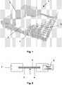
- the loudspeaker 1comprises a multi-layer panel consisting essentially of three or more layers of thin, flexible material, and more particularly an electrically insulating middle layer 2 sandwiched between top and bottom electrically conducting outer layers 3 and 4.
- the middle layer 2is a polymer membrane optionally having a profiled surface having circular pits (not shown) in contact with the top outer layer 3.
- the top outer layer 3comprises a thin polymer membrane provided with a layer of metallisation applied to its outer surface by a known metallisation process, such as vapour deposition. Although the top outer layer 3 is shown as a separate layer in Figure 1 , this outer layer 3 may be replaced by a layer of metallisation applied to the back surface of the middle layer 2 by a conventional metallisation process.
- the top outer layer 3may be made from, for example, domestic aluminium foil, metallised foil, paper coated with a layer of conducting paint or copper foil.
- a thin polymer membrane provided with a layer of metalisation on its outer surfaceis preferred. This has a very low mass and is therefore better able to couple its motion to the air generating the sound.
- the displayitself can be used as a layer in the loudspeaker.
- the middle layer 2may be made from, for example, paper, greaseproof paper, cloth or plastic. However it would appear that the output is optimised if a polymer membrane is used. Usually this middle layer 2 does not require any kind of profiling in order to optimise the audio reproduction. However profiling of this layer is not excluded. This layer may be permanently electrostatically charged to eliminate or minimise the applied DC bias.
- the bottom outer layer 4is a thin porous conducting membrane comprising a regular matrix of holes extending through the layer 4.
- the use of a porous bottom layer 4helps facilitate the movement of the membranes of the loudspeaker as it ensures the other membranes are not constrained against any forward movement by a pressure imbalance, in the form of a partial vacuum behind the insulating middle layer 2.
- the porous bottom layer 4may, by way of example, be formed from an interwoven mesh of aluminium wire of 0.1 mm diameter comprising parallel strands of wire extending in one direction woven together with strands of wire extending in a perpendicular direction using a twill weave pattern (a twill weave is formed by individual strands going over two strands and then under two strands).
- the size of the aperture between the wiresis typically 0.11 mm and the number of wires used per inch is typically 120.
- the percentage of open area, governed by the gauge of the wire,is approximately 27%.
- a d.c. power supply 7is provided for supplying a d.c. potential, of, for example, 300V across the top and bottom conducting layers 3 and 4.
- a signal generator 8is connected across the top and bottom conducting layers 3 and 4 for applying an alternating signal to drive the loudspeaker 1.
- capacitative decouplingmay be used to separate the d.c. and a.c. voltages.
- the d.c. potentialcauses the top outer layer 3 to be drawn onto the bottom layer 4.
- the audio (AC) signalis applied by the signal generator 8 across the outer layers 3 and 4
- the electrostatic forces acting between the layers 3 and 2are caused to vary and this in turn causes the layers to vibrate and the air immediately above it generates the required sound.
- the construction of the speakeris also key to the quality of the reproduced sound.
- both conducting layerswill vibrate as a rigid piston across the entire area to produce sound.
- the application of the DC biascauses the top layer to be drawn onto the middle layer which in turn is drawn onto the bottom layer.
- the electrostatic forces acting between the layersare caused to vary and this in turn causes the layers to vibrate.
- the layers move as a whole in operationit is important for the layers to be uniform across their surfaces. Any slight deviation caused, for example, by a crease or crinkle will alter the force felt by the layers at that point, thus altering the motion and leading to distortion in the reproduced audio signal.
- Such a loudspeakerdoes not require the large voltages required by conventional electrostatic loudspeakers since the electrostatic field is large because the separation of the electrodes is small.
- a reasonably small voltage(for example 36V) may therefore be used to produce such an electric field, although higher voltages of 300V may be required in some cases to generate larger acoustic amplitudes.
- the first outer layer 3may be profiled instead of (or in addition to) the middle layer 2.
- the d.c. supplymay be eliminated completely by using a permanently charged material for the membrane and/or the middle layer 2.
- the middle layeris formed by a sheet of a thin porous material, such as paper or tissue. Use of a porous middle layer 2 helps the movement of the top layer in that it is not constrained against movement in the forward direction (i.e. away from the middle layer) by a pressure imbalance, in the form of a partial vacuum behind the layer. This is particularly so for lower acoustic frequencies which require greater displacements, and would generate a greater partial vacuum.
- the compressibility of a materialsuch as paper or tissue provides a resilient force which complements or replaces the drumskin tensional forces described previously.
- Figure 3shows a drive circuit, which may be used to drive such a loudspeaker, having an audio input 10 for receiving an audio input signal to be amplified by a preamplifier 12.
- the signalis then applied to a pair of MOSFET's 13, 14 which are biased by resistors 18, 19 and supplied with power from a voltage supply rail 20, which is typically connected to a +200V supply.
- the output 15 from this circuitis connected to drive the loudspeakers.
- resistors 16, 17, 21the output can be adjusted to have a suitable d.c. bias voltage, as well as an a.c. signal voltage.
- the loudspeakers in accordance with the invention described aboveare not only very thin, i.e. less than 0.5 mm, but are also flexible allowing them to be easily contoured.
- Such contouringcan either be used to fit the loudspeaker to suit its environment, for example to fit within a room with curved walls or within a curved computer casing or screen, or to modify the emitted acoustic field, for example by being made concave to focus the sound or convex to spread the sound.
- Such a loudspeakercan be adapted very easily to have a frequency bandwidth in air well above the audible range, up to 2 MHz. Whilst such loudspeaker may have poorer low-frequency response, this can be improved by careful design of the loudspeaker components.
- the loudspeakersare inherently efficient at generating sound from electrical signals and can consequently be considered to be low power. This is of particular advantage where power consumption is at a premium, for example with battery powered devices such as notebook computers, novelty Christmas cards, or even novel audio advertising posters. There are advantages in having high electrical efficiency loudspeakers with very-high power public address systems, such as are heard at rock concerts.
- the ability to produce large areas of loudspeaker at relatively low cost using such a constructionalso offers novel applications for home audio systems, allowing loudspeakers to be hung as wallpaper on walls or ceilings.
- large area sound sourceshave potential advantages for the sound field of such audio systems.
- a permanently charged polymer filmis attached to the rear of the loudspeaker, the resulting electrostatic forces can be used to stick the loudspeaker to the wall, enabling the loudspeaker to be rolled up and moved to a new location when required.
- a further application of the inventionis to noise cancellation systems in which ambient noise is cancelled by the generation of anti-noise by a loudspeaker component in accordance with the invention.
Landscapes
- Physics & Mathematics (AREA)
- Engineering & Computer Science (AREA)
- Acoustics & Sound (AREA)
- Signal Processing (AREA)
- Piezo-Electric Transducers For Audible Bands (AREA)
- Electrostatic, Electromagnetic, Magneto- Strictive, And Variable-Resistance Transducers (AREA)
Description
- Loudspeakers can generally be grouped into three classes of device, namely electrostatic (coil and magnet), piezoelectric and capacitative. Electromagnetic loudspeakers are used in many applications, such as hi-fi systems, radios, televisions and computers. They generate high quality sound and are cheap to produce and are well established, however they suffer from the fact that they are relatively bulky and heavy, and have limited control over the directionality of the generated sound. Whilst electromagnetic loudspeakers can be made which cover the range of frequency from sub-audio (10 Hz) to the top of the hearing range (20 kHz), it is usual for two or three separate loudspeakers to be used together to span the whole audio frequency range if high fidelity reproduction is required.
- Loudspeakers based on piezoelectric principles are currently of considerable interest as they can be used to produce flat loudspeakers which are relatively thin (several mm), and are particularly advantageous where space is at a premium, for example in aircraft or in cars. However such loudspeakers can be relatively expensive to produce and are inflexible, limiting their flexibility of use.
- Other Piezoelectric sound sources (with very low sound quality) are produced, and an example of this class of piezoelectric sound source is the "unimorph" used in singing Christmas cards.
- Recently, flat panel loudspeakers have appeared on the market, which have a distributed mode source, offering better directionality that has been possible with previous loudspeaker arrangements. These are flat, but still require an excitation mechanism (generally an electromagnetic arrangement, but variants using piezoelectric excitation are possible). There is a maximum size of this class of transducer, meaning that large area sources (desired for some applications) must be made from an array of these devices, limiting the directionality of the source.
- Electrostatic loudspeakers are often considered to give the highest quality audio reproduction. Generally such loudspeakers use an electrically conducting thin membrane between two electrode planes. During operation the membrane is electrostatically charged with a high (DC) polarising voltage. If an (AC) audio signal is applied between the two electrode planes a varying electric field will be established which will have the effect of causing the diaphragm to move back and forth at the frequency of this voltage generating sound. However such loudspeakers use very high voltages (1000V and above) and require a bulky enclosure. They also have reduced low-frequency (bass) response.
US3942029 describes an electrostatic transducer based on an electret diaphragm clamped between two fixed and rigid electrodes. The electret diaphragm is spaced apart from the fixed electrodes by an annular spacer and support rings, which produces an air gap between the electret diaphragm and the fixed electrodes. Only the electret diaphragm vibrates to generate acoustic sound within the air gap. Similarly,DE2330800 describes a three terminal electroacoustic transducer in which the vibrating diaphragm (or electret) is electrically conducting and is tensioned and clamped between the two spaced apart fixed electrodes. A signal generator is electrically connected to the two fixed electrodes and the vibrating diaphragm.GB 356778 WO02/19764 - It is an object of the present invention to provide a novel electrostatic loudspeaker which is capable of better quality and louder sound reproduction than that disclosed in
WO02/19764 - According to the present invention there is provided an electrostatic audio loudspeaker comprising a flexible multi-layer panel incorporating a flexible electrically insulating middle membrane, a first flexible electrically conducting outer membrane, and a second flexible electrically conducting outer membrane, where the middle membrane is sandwiched between first and second electrically conducting outer membranes, and signal generating means for applying an alternating electrical voltage across the first and second electrically conducting outer membranes to initiate vibration due to variation of the electrostatic forces acting between the first and second outer membranes, wherein the first and second electrically conducting outer membranes are electrically connected to the signal generating means and the three membranes are sandwiched so as to be capable of vibrating relative to one another and at least one of the first and second outer membranes being permeable to air displaced by such vibration.
- One (or more) of the outer membranes may be manufactured from a porous material, such as a mesh. Furthermore one or more of the membranes may be profiled to increase sound output and quality, although this is not always necessary.
- Such a loudspeaker can serve as a low cost audio loudspeaker which can be made lightweight and flexible so as to render it suitable for a wide range of applications. For example such a loudspeaker may be in the form of a large area sheet which can be directly mounted on or close to a wall to provide sound reproduction in a home environment without the need for a bulky enclosure, or in a public address system such as may be required in a railway station. Furthermore such a loudspeaker would be particularly suitable for use in applications where space is at a particular premium, for example in a notebook computer or mobile telephone, or integrated into a thin-film flexible display. Since the loudspeaker may also be made transparent or translucent, it would be possible to incorporate it in a computer screen or in a car side window. Because such a loudspeaker can be produced at low cost, it may also be suitable for novelty items, such as noisy posters and talking or singing cards.
- The ability to have large (or small) area acoustic sources, operating in a "planar piston" mode, with the capacity to shape the source, and have an easily manufactured array of sources (all of which are possible features of embodiments of the invention) allows a designer of sound systems great control over the directionality of the sound field. For example a large, flat area source may produce a directional beam of sound, which may be desirable in an airport for zoning messages, i.e. only giving sound messages in a particular area. or in a supermarket for advertising a product only in the area in which the product is being displayed.
- In order that the invention may be more fully understood, reference will now be made, by way of example, to the accompanying drawings, in which:
Figure 1 is a partly cut-away view of part of a preferred embodiment of the invention;Figure 2 is a generalised diagram of a drive circuit for use with the preferred embodiment of the invention; andFigure 3 is a circuit diagram of a drive circuit suitable for use with the preferred embodiment of the invention.- A preferred embodiment of
loudspeaker 1 in accordance with the invention will now be described with reference toFigures 1 and 2 . Theloudspeaker 1 comprises a multi-layer panel consisting essentially of three or more layers of thin, flexible material, and more particularly an electrically insulatingmiddle layer 2 sandwiched between top and bottom electrically conductingouter layers middle layer 2 is a polymer membrane optionally having a profiled surface having circular pits (not shown) in contact with the topouter layer 3. The topouter layer 3 comprises a thin polymer membrane provided with a layer of metallisation applied to its outer surface by a known metallisation process, such as vapour deposition. Although the topouter layer 3 is shown as a separate layer inFigure 1 , thisouter layer 3 may be replaced by a layer of metallisation applied to the back surface of themiddle layer 2 by a conventional metallisation process. - The top
outer layer 3 may be made from, for example, domestic aluminium foil, metallised foil, paper coated with a layer of conducting paint or copper foil. However, in order to maximise the output from the loudspeaker, a thin polymer membrane provided with a layer of metalisation on its outer surface is preferred. This has a very low mass and is therefore better able to couple its motion to the air generating the sound. In the case of a thin-film display, the display itself can be used as a layer in the loudspeaker. - The
middle layer 2 may be made from, for example, paper, greaseproof paper, cloth or plastic. However it would appear that the output is optimised if a polymer membrane is used. Usually thismiddle layer 2 does not require any kind of profiling in order to optimise the audio reproduction. However profiling of this layer is not excluded. This layer may be permanently electrostatically charged to eliminate or minimise the applied DC bias. - Furthermore at least one of the two electrically-conducting outer layers is porous, that is permeable to air generated by vibration of the loudspeaker. In the illustrated embodiment the bottom
outer layer 4 is a thin porous conducting membrane comprising a regular matrix of holes extending through thelayer 4. The use of aporous bottom layer 4 helps facilitate the movement of the membranes of the loudspeaker as it ensures the other membranes are not constrained against any forward movement by a pressure imbalance, in the form of a partial vacuum behind theinsulating middle layer 2. - The
porous bottom layer 4 may, by way of example, be formed from an interwoven mesh of aluminium wire of 0.1 mm diameter comprising parallel strands of wire extending in one direction woven together with strands of wire extending in a perpendicular direction using a twill weave pattern (a twill weave is formed by individual strands going over two strands and then under two strands). The size of the aperture between the wires is typically 0.11 mm and the number of wires used per inch is typically 120. The percentage of open area, governed by the gauge of the wire, is approximately 27%. - From experimentation it has been found that forcing the mesh through a pair of precision rollers, such that the individual wires forming the mesh are flattened across their outer surface (which is referred to as calenderisation) increases the sound pressure level from the loudspeaker.
- As shown diagrammatically in
Figure 2 , a d.c.power supply 7 is provided for supplying a d.c. potential, of, for example, 300V across the top andbottom conducting layers signal generator 8 is connected across the top andbottom conducting layers loudspeaker 1. Although not shown inFigure 2 , capacitative decoupling may be used to separate the d.c. and a.c. voltages. The d.c. potential causes the topouter layer 3 to be drawn onto thebottom layer 4. When the audio (AC) signal is applied by thesignal generator 8 across theouter layers layers - The construction of the speaker is also key to the quality of the reproduced sound. When an a.c. signal is applied both conducting layers will vibrate as a rigid piston across the entire area to produce sound. It should be noted that, with a mass difference between the conducting layers, most of the vibration can occur in the top layer. The application of the DC bias causes the top layer to be drawn onto the middle layer which in turn is drawn onto the bottom layer. When an audio signal is applied, the electrostatic forces acting between the layers are caused to vary and this in turn causes the layers to vibrate. As the layers move as a whole in operation, it is important for the layers to be uniform across their surfaces. Any slight deviation caused, for example, by a crease or crinkle will alter the force felt by the layers at that point, thus altering the motion and leading to distortion in the reproduced audio signal.
- Such a loudspeaker does not require the large voltages required by conventional electrostatic loudspeakers since the electrostatic field is large because the separation of the electrodes is small. A reasonably small voltage (for example 36V) may therefore be used to produce such an electric field, although higher voltages of 300V may be required in some cases to generate larger acoustic amplitudes.
- In a variation of such a loudspeaker the first
outer layer 3 may be profiled instead of (or in addition to) themiddle layer 2. In a further variation the d.c. supply may be eliminated completely by using a permanently charged material for the membrane and/or themiddle layer 2. In a further variation the middle layer is formed by a sheet of a thin porous material, such as paper or tissue. Use of a porousmiddle layer 2 helps the movement of the top layer in that it is not constrained against movement in the forward direction (i.e. away from the middle layer) by a pressure imbalance, in the form of a partial vacuum behind the layer. This is particularly so for lower acoustic frequencies which require greater displacements, and would generate a greater partial vacuum. For movement in the reverse direction (towards the middle layer) the compressibility of a material such as paper or tissue provides a resilient force which complements or replaces the drumskin tensional forces described previously. Figure 3 shows a drive circuit, which may be used to drive such a loudspeaker, having an audio input 10 for receiving an audio input signal to be amplified by apreamplifier 12. The signal is then applied to a pair of MOSFET's 13, 14 which are biased byresistors voltage supply rail 20, which is typically connected to a +200V supply. Theoutput 15 from this circuit is connected to drive the loudspeakers. By careful choice ofresistors - Because of the thinness of the layers, the loudspeakers in accordance with the invention described above are not only very thin, i.e. less than 0.5 mm, but are also flexible allowing them to be easily contoured. Such contouring can either be used to fit the loudspeaker to suit its environment, for example to fit within a room with curved walls or within a curved computer casing or screen, or to modify the emitted acoustic field, for example by being made concave to focus the sound or convex to spread the sound. Such a loudspeaker can be adapted very easily to have a frequency bandwidth in air well above the audible range, up to 2 MHz. Whilst such loudspeaker may have poorer low-frequency response, this can be improved by careful design of the loudspeaker components.
- The thin profile of such loudspeakers gives them an advantage over more conventional loudspeakers in applications where space is at a premium, for example in notebook computers and mobile telephones. Furthermore, by using transparent polymers and electrodes, it would be possible to produce transparent loudspeaker panels which can be used either in front of computer screens, giving advantages in terms of directionality of sound, or within car windows, both for the purposes of audio reproduction and noise reduction. The low weight of the loudspeakers, together with their thin profile, also offers considerable potential for use in aerospace and other specialist applications, either for audio reproduction or for noise cancellation.
- The loudspeakers are inherently efficient at generating sound from electrical signals and can consequently be considered to be low power. This is of particular advantage where power consumption is at a premium, for example with battery powered devices such as notebook computers, novelty Christmas cards, or even novel audio advertising posters. There are advantages in having high electrical efficiency loudspeakers with very-high power public address systems, such as are heard at rock concerts.
- The ability to produce large areas of loudspeaker at relatively low cost using such a construction also offers novel applications for home audio systems, allowing loudspeakers to be hung as wallpaper on walls or ceilings. In this regard large area sound sources have potential advantages for the sound field of such audio systems. Furthermore, if a permanently charged polymer film is attached to the rear of the loudspeaker, the resulting electrostatic forces can be used to stick the loudspeaker to the wall, enabling the loudspeaker to be rolled up and moved to a new location when required.
- It would also be a relatively straightforward task to enable a single loudspeaker sheet to be separated into separate elements, either by cutting the sheet or by screenprinting rear electrodes in multiple areas. This would provide the ability to produce very high quality surround sound by controlling separate speaker elements to provide the required audio image in a sound stage.
- A further application of the invention is to noise cancellation systems in which ambient noise is cancelled by the generation of anti-noise by a loudspeaker component in accordance with the invention.
Claims (16)
- An electrostatic loudspeaker comprising:a flexible multi-layer panel incorporating:a flexible electrically insulating middle membrane (2);a first flexible electrically conducting outer membrane (3); anda second flexible electrically conducting outer membrane (4);wherein the middle membrane is sandwiched between the first and second electrically conducting outer membranes (3, 4); andsignal generating means (8) for applying an alternating electrical voltage across the first and second electrically conducting outer membranes (3, 4) to initiate vibration due to variation of the electrostatic forces acting between the first and second outer membranes (3, 4);wherein the first and second electrically conducting outer membranes are electrically connected to the signal generating means (8) and the three membranes (2, 3, 4) are sandwiched so as to be capable of vibrating relative to one another and at least one of the first and second outer membranes (3, 4) being permeable to air displaced by such vibration.
- A loudspeaker according to claim 1, wherein at least one of the outer membranes (3, 4) is provided with a regular matrix of holes extending therethrough.
- A loudspeaker according to claim 1 or 2, wherein at least one of the outer membranes (3, 4) is in the form of a woven mesh.
- A loudspeaker according to claim 1, 2 or 3, wherein biasing means (7) is provided for applying a steady-state bias potential across the outer membranes (3, 4).
- A loudspeaker according to claim 4, wherein the middle membrane (2) and the first and second outer membranes (3, 4) are arranged such that the steady-state bias potential across the outer membranes (3, 4) causes the first outer membrane (3) to be drawn onto the middle membrane (2) which in turn is drawn onto the second outer membrane (4).
- A loudspeaker according to claim 4 or 5, wherein means are provided for capacitatively decoupling the steady-state bias potential applied by the biasing means (7) from the alternating voltage generated by the signal generating means (8).
- A loudspeaker according to any preceding claim, wherein the middle membrane (2) is electrostatically charged such that the first and second outer membranes (3, 4) are drawn to the middle membrane (2).
- A loudspeaker according to any preceding claim, wherein the middle membrane (2) is made of a polymeric material.
- A loudspeaker according to any preceding claim, wherein at least one of the outer membranes (3, 4) comprises an electrically conducting film applied to the outer surface of an electrically insulating membrane.
- A loudspeaker according to claim 9, wherein the electrically insulating membrane of the at least one outer membrane (3, 4) is made of a polymeric material.
- A loudspeaker according to any preceding claim, wherein the middle membrane (2) has a profiled surface in contact with the first outer membrane (3), and the second outer membrane (4) is permeable to air displaced by the vibration.
- A loudspeaker according to claim 11, wherein the middle membrane (2) is provided with pits over which the first outer membrane (3) extends.
- A loudspeaker according to any preceding claim, wherein the multi-layer panel has a thickness of less than 0.5 mm.
- A loudspeaker according to any preceding claim, wherein the multi-layer panel is at least partly transparent.
- A loudspeaker according to any preceding claim, wherein a plurality of loudspeakers are provided on a single panel.
- A loudspeaker according to any preceding claim, wherein the first outer membrane (3) and the second outer membrane (4) are arranged so that a mass difference between the first and second outer membranes (3, 4) causes most of the vibration to occur in the first outer membrane (3) when the alternating voltage is applied across the first and second outer membranes (3, 4).
Applications Claiming Priority (2)
| Application Number | Priority Date | Filing Date | Title |
|---|---|---|---|
| GBGB0600014.5AGB0600014D0 (en) | 2006-01-03 | 2006-01-03 | Electrostatic loudspeakers |
| PCT/GB2006/050468WO2007077438A1 (en) | 2006-01-03 | 2006-12-19 | Electrostatic loudspeakers |
Publications (2)
| Publication Number | Publication Date |
|---|---|
| EP1972178A1 EP1972178A1 (en) | 2008-09-24 |
| EP1972178B1true EP1972178B1 (en) | 2019-06-19 |
Family
ID=35841433
Family Applications (1)
| Application Number | Title | Priority Date | Filing Date |
|---|---|---|---|
| EP06820693.7AActiveEP1972178B1 (en) | 2006-01-03 | 2006-12-19 | Electrostatic loudspeakers |
Country Status (6)
| Country | Link |
|---|---|
| US (1) | US8416973B2 (en) |
| EP (1) | EP1972178B1 (en) |
| JP (1) | JP5075836B2 (en) |
| CN (1) | CN101395957B (en) |
| GB (1) | GB0600014D0 (en) |
| WO (1) | WO2007077438A1 (en) |
Families Citing this family (24)
| Publication number | Priority date | Publication date | Assignee | Title |
|---|---|---|---|---|
| US8625824B2 (en) | 2007-09-04 | 2014-01-07 | Industrial Technology Research Institute | Flat speaker unit and speaker device therewith |
| TWI330500B (en)* | 2007-09-04 | 2010-09-11 | Ind Tech Res Inst | Speaker structure |
| CN101494810B (en)* | 2008-01-22 | 2013-02-06 | 普诚科技股份有限公司 | Sound playing device and method thereof |
| US8666097B2 (en)* | 2009-09-30 | 2014-03-04 | Yamaha Corporation | Electrostatic speaker |
| US8831253B2 (en) | 2009-10-22 | 2014-09-09 | Industrial Technology Research Institute | Electroacoustic apparatus with optical energy conversion function |
| TW201204062A (en)* | 2010-07-15 | 2012-01-16 | Taiwan Electrets Electronics Co Ltd | Electrostatic speaker and manufacturing method thereof and conducting plate of the speaker |
| GB2490930A (en)* | 2011-05-19 | 2012-11-21 | Warwick Audio Technologies Ltd | A switching amplifier arrangement providing both signal drive and a high bias voltage for an electrostatic loudspeaker |
| GB2490931A (en) | 2011-05-19 | 2012-11-21 | Warwick Audio Technologies Ltd | Electrostatic acoustic transducer |
| US9417213B1 (en)* | 2011-07-11 | 2016-08-16 | The Boeing Company | Non-destructive evaluation system for aircraft |
| RU2547897C2 (en)* | 2013-07-26 | 2015-04-10 | Открытое акционерное общество "Военно-промышленная корпорация "Научно-производственное объединение машиностроения" | Wide-beam electrostatic loudspeaker |
| DE102013225046A1 (en)* | 2013-12-05 | 2015-06-11 | Lufthansa Technik Ag | Aircraft engine, passenger aircraft, active noise reduction method, and method of retrofitting a gas turbine aircraft engine |
| GB2522931A (en) | 2014-02-11 | 2015-08-12 | Warwick Audio Technologies Ltd | Improved electrostatic transducer |
| GB2522932A (en) | 2014-02-11 | 2015-08-12 | Warwick Audio Technologies Ltd | Improved electrostatic transducer |
| KR102369124B1 (en) | 2014-12-26 | 2022-03-03 | 삼성디스플레이 주식회사 | Image display apparatus |
| US9725047B2 (en)* | 2015-06-22 | 2017-08-08 | Ford Global Technologies, Llc | Loudspeaker arrangement in a vehicle |
| CN105228065A (en)* | 2015-11-02 | 2016-01-06 | 李崇 | There is the wafer speaker of good acoustical quality |
| CN106454667B (en)* | 2016-08-24 | 2022-04-22 | 深圳市炜鼎科技有限公司 | Electrostatic speaker system |
| KR102691540B1 (en) | 2016-11-04 | 2024-08-05 | 삼성전자주식회사 | Planar magnet speaker |
| CN112334867A (en) | 2018-05-24 | 2021-02-05 | 纽约州立大学研究基金会 | Capacitive sensor |
| US11153690B2 (en)* | 2018-08-22 | 2021-10-19 | Dsp Group Ltd. | Electrostatic speaker and a method for generating acoustic signals |
| CN110087175A (en)* | 2019-04-17 | 2019-08-02 | 海菲曼(天津)科技有限公司 | A kind of electrostatic loudspeaker stator plate and electrostatic loudspeaker |
| GB201906425D0 (en) | 2019-05-07 | 2019-06-19 | Warwick Acoustics Ltd | Electrostatic transducer and diaphragm |
| WO2024257668A1 (en)* | 2023-06-14 | 2024-12-19 | 旭化成株式会社 | Automobile interior material including flexible thin speaker |
| TWI870019B (en)* | 2023-09-13 | 2025-01-11 | 英業達股份有限公司 | Method for arranging the electrostatic loudspeaker at the laptop computer |
Citations (2)
| Publication number | Priority date | Publication date | Assignee | Title |
|---|---|---|---|---|
| US1764008A (en)* | 1928-10-24 | 1930-06-17 | United Reproducers Patents Cor | Push-pull electrostatic sound reproducer |
| GB2245451A (en)* | 1990-04-13 | 1992-01-02 | Sansui Electric Co | Diaphragm for speaker |
Family Cites Families (13)
| Publication number | Priority date | Publication date | Assignee | Title |
|---|---|---|---|---|
| US1759809A (en) | 1929-04-03 | 1930-05-20 | Ephraim Banning | Acoustic condenser |
| DE2330800C3 (en) | 1973-06-16 | 1981-10-01 | Sennheiser Electronic Kg, 3002 Wedemark | Electroacoustic transducer based on the electrostatic principle and process for its manufacture |
| JPS5419172B2 (en)* | 1973-07-23 | 1979-07-13 | ||
| US4515997A (en)* | 1982-09-23 | 1985-05-07 | Stinger Jr Walter E | Direct digital loudspeaker |
| US4533794A (en) | 1983-05-23 | 1985-08-06 | Beveridge Harold N | Electrode for electrostatic transducer |
| AT386505B (en)* | 1986-12-09 | 1988-09-12 | Akg Akustische Kino Geraete | ELECTROACOUSTIC OR ELECTROMECHANICAL TRANSDUCER ACCORDING TO THE ELECTROSTATIC CONVERSION PRINCIPLE |
| JP3246685B2 (en)* | 1993-02-18 | 2002-01-15 | フオスター電機株式会社 | Electroacoustic transducer |
| JP3502524B2 (en)* | 1997-02-19 | 2004-03-02 | 日本碍子株式会社 | Transducer array |
| US7095864B1 (en) | 2000-09-02 | 2006-08-22 | University Of Warwick | Electrostatic audio loudspeakers |
| JP3662505B2 (en)* | 2001-03-16 | 2005-06-22 | シャープ株式会社 | Time display device with integrated transparent speaker and microphone |
| DE10300063A1 (en) | 2003-01-03 | 2004-07-22 | W.L. Gore & Associates Gmbh | Membrane for acoustic transducers |
| US6943448B2 (en)* | 2003-01-23 | 2005-09-13 | Akustica, Inc. | Multi-metal layer MEMS structure and process for making the same |
| JP3873990B2 (en)* | 2004-06-11 | 2007-01-31 | セイコーエプソン株式会社 | Ultrasonic transducer and ultrasonic speaker using the same |
- 2006
- 2006-01-03GBGBGB0600014.5Apatent/GB0600014D0/ennot_activeCeased
- 2006-12-19CNCN200680053688.3Apatent/CN101395957B/enactiveActive
- 2006-12-19EPEP06820693.7Apatent/EP1972178B1/enactiveActive
- 2006-12-19WOPCT/GB2006/050468patent/WO2007077438A1/enactiveApplication Filing
- 2006-12-19USUS12/159,882patent/US8416973B2/enactiveActive
- 2006-12-19JPJP2008549054Apatent/JP5075836B2/enactiveActive
Patent Citations (2)
| Publication number | Priority date | Publication date | Assignee | Title |
|---|---|---|---|---|
| US1764008A (en)* | 1928-10-24 | 1930-06-17 | United Reproducers Patents Cor | Push-pull electrostatic sound reproducer |
| GB2245451A (en)* | 1990-04-13 | 1992-01-02 | Sansui Electric Co | Diaphragm for speaker |
Also Published As
| Publication number | Publication date |
|---|---|
| EP1972178A1 (en) | 2008-09-24 |
| JP2009522899A (en) | 2009-06-11 |
| WO2007077438A1 (en) | 2007-07-12 |
| CN101395957B (en) | 2013-03-20 |
| GB0600014D0 (en) | 2006-02-08 |
| JP5075836B2 (en) | 2012-11-21 |
| CN101395957A (en) | 2009-03-25 |
| US8416973B2 (en) | 2013-04-09 |
| US20090016552A1 (en) | 2009-01-15 |
Similar Documents
| Publication | Publication Date | Title |
|---|---|---|
| EP1972178B1 (en) | Electrostatic loudspeakers | |
| JP2009522899A5 (en) | ||
| USRE40860E1 (en) | Electrostatic audio loudspeakers | |
| CN101656904B (en) | speaker system | |
| US4246448A (en) | Electromechanical transducer | |
| US3345469A (en) | Electrostatic loudspeakers | |
| US6188772B1 (en) | Electrostatic speaker with foam stator | |
| KR100574711B1 (en) | Speaker device and sound wave energy propagation method | |
| CN1997243A (en) | Pliable loudspeaker and its making method | |
| CN102082987B (en) | Sound equipment actuating device and sound equipment actuating device system | |
| CN110505557A (en) | A speaker and terminal equipment | |
| JP3502524B2 (en) | Transducer array | |
| US6819769B1 (en) | Electrolytic loudspeaker assembly | |
| Klug et al. | Design, fabrication, and customized driving of dielectric loudspeaker arrays | |
| EP3105941B1 (en) | Improved electrostatic transducer | |
| JP2002535945A (en) | Composite electrolytic speaker assembly | |
| JP6495866B2 (en) | Speaker unit | |
| US8085957B2 (en) | Method for converting electric signals into acoustic oscillations and an electric gas-kinetic transducer | |
| JP4862700B2 (en) | Electrostatic speaker | |
| Ko et al. | Study and application of free-form electret actuators | |
| KR102855978B1 (en) | Sound generator capable of changing membrane dynamic properties through tension control | |
| JP2007274342A (en) | Electrostatic speaker | |
| JP2013051665A (en) | Electro acoustic transducer and cover for electro acoustic transducer | |
| JP2007274363A (en) | Electrostatic speaker |
Legal Events
| Date | Code | Title | Description |
|---|---|---|---|
| PUAI | Public reference made under article 153(3) epc to a published international application that has entered the european phase | Free format text:ORIGINAL CODE: 0009012 | |
| 17P | Request for examination filed | Effective date:20080724 | |
| AK | Designated contracting states | Kind code of ref document:A1 Designated state(s):AT BE BG CH CY CZ DE DK EE ES FI FR GB GR HU IE IS IT LI LT LU LV MC NL PL PT RO SE SI SK TR | |
| 17Q | First examination report despatched | Effective date:20120201 | |
| DAX | Request for extension of the european patent (deleted) | ||
| RAP1 | Party data changed (applicant data changed or rights of an application transferred) | Owner name:WARWICK AUDIO TECHNOLOGIES LIMITED | |
| STAA | Information on the status of an ep patent application or granted ep patent | Free format text:STATUS: EXAMINATION IS IN PROGRESS | |
| GRAP | Despatch of communication of intention to grant a patent | Free format text:ORIGINAL CODE: EPIDOSNIGR1 | |
| STAA | Information on the status of an ep patent application or granted ep patent | Free format text:STATUS: GRANT OF PATENT IS INTENDED | |
| INTG | Intention to grant announced | Effective date:20190103 | |
| RAP1 | Party data changed (applicant data changed or rights of an application transferred) | Owner name:WARWICK ACOUSTICS LIMITED | |
| GRAS | Grant fee paid | Free format text:ORIGINAL CODE: EPIDOSNIGR3 | |
| GRAA | (expected) grant | Free format text:ORIGINAL CODE: 0009210 | |
| STAA | Information on the status of an ep patent application or granted ep patent | Free format text:STATUS: THE PATENT HAS BEEN GRANTED | |
| AK | Designated contracting states | Kind code of ref document:B1 Designated state(s):AT BE BG CH CY CZ DE DK EE ES FI FR GB GR HU IE IS IT LI LT LU LV MC NL PL PT RO SE SI SK TR | |
| REG | Reference to a national code | Ref country code:GB Ref legal event code:FG4D | |
| REG | Reference to a national code | Ref country code:CH Ref legal event code:EP | |
| REG | Reference to a national code | Ref country code:IE Ref legal event code:FG4D | |
| REG | Reference to a national code | Ref country code:DE Ref legal event code:R096 Ref document number:602006058181 Country of ref document:DE | |
| REG | Reference to a national code | Ref country code:AT Ref legal event code:REF Ref document number:1147041 Country of ref document:AT Kind code of ref document:T Effective date:20190715 | |
| REG | Reference to a national code | Ref country code:NL Ref legal event code:MP Effective date:20190619 | |
| PG25 | Lapsed in a contracting state [announced via postgrant information from national office to epo] | Ref country code:FI Free format text:LAPSE BECAUSE OF FAILURE TO SUBMIT A TRANSLATION OF THE DESCRIPTION OR TO PAY THE FEE WITHIN THE PRESCRIBED TIME-LIMIT Effective date:20190619 Ref country code:LT Free format text:LAPSE BECAUSE OF FAILURE TO SUBMIT A TRANSLATION OF THE DESCRIPTION OR TO PAY THE FEE WITHIN THE PRESCRIBED TIME-LIMIT Effective date:20190619 Ref country code:SE Free format text:LAPSE BECAUSE OF FAILURE TO SUBMIT A TRANSLATION OF THE DESCRIPTION OR TO PAY THE FEE WITHIN THE PRESCRIBED TIME-LIMIT Effective date:20190619 | |
| REG | Reference to a national code | Ref country code:LT Ref legal event code:MG4D | |
| PG25 | Lapsed in a contracting state [announced via postgrant information from national office to epo] | Ref country code:GR Free format text:LAPSE BECAUSE OF FAILURE TO SUBMIT A TRANSLATION OF THE DESCRIPTION OR TO PAY THE FEE WITHIN THE PRESCRIBED TIME-LIMIT Effective date:20190920 Ref country code:BG Free format text:LAPSE BECAUSE OF FAILURE TO SUBMIT A TRANSLATION OF THE DESCRIPTION OR TO PAY THE FEE WITHIN THE PRESCRIBED TIME-LIMIT Effective date:20190919 Ref country code:LV Free format text:LAPSE BECAUSE OF FAILURE TO SUBMIT A TRANSLATION OF THE DESCRIPTION OR TO PAY THE FEE WITHIN THE PRESCRIBED TIME-LIMIT Effective date:20190619 | |
| REG | Reference to a national code | Ref country code:AT Ref legal event code:MK05 Ref document number:1147041 Country of ref document:AT Kind code of ref document:T Effective date:20190619 | |
| PG25 | Lapsed in a contracting state [announced via postgrant information from national office to epo] | Ref country code:SK Free format text:LAPSE BECAUSE OF FAILURE TO SUBMIT A TRANSLATION OF THE DESCRIPTION OR TO PAY THE FEE WITHIN THE PRESCRIBED TIME-LIMIT Effective date:20190619 Ref country code:EE Free format text:LAPSE BECAUSE OF FAILURE TO SUBMIT A TRANSLATION OF THE DESCRIPTION OR TO PAY THE FEE WITHIN THE PRESCRIBED TIME-LIMIT Effective date:20190619 Ref country code:PT Free format text:LAPSE BECAUSE OF FAILURE TO SUBMIT A TRANSLATION OF THE DESCRIPTION OR TO PAY THE FEE WITHIN THE PRESCRIBED TIME-LIMIT Effective date:20191021 Ref country code:AT Free format text:LAPSE BECAUSE OF FAILURE TO SUBMIT A TRANSLATION OF THE DESCRIPTION OR TO PAY THE FEE WITHIN THE PRESCRIBED TIME-LIMIT Effective date:20190619 Ref country code:NL Free format text:LAPSE BECAUSE OF FAILURE TO SUBMIT A TRANSLATION OF THE DESCRIPTION OR TO PAY THE FEE WITHIN THE PRESCRIBED TIME-LIMIT Effective date:20190619 Ref country code:RO Free format text:LAPSE BECAUSE OF FAILURE TO SUBMIT A TRANSLATION OF THE DESCRIPTION OR TO PAY THE FEE WITHIN THE PRESCRIBED TIME-LIMIT Effective date:20190619 Ref country code:CZ Free format text:LAPSE BECAUSE OF FAILURE TO SUBMIT A TRANSLATION OF THE DESCRIPTION OR TO PAY THE FEE WITHIN THE PRESCRIBED TIME-LIMIT Effective date:20190619 | |
| PG25 | Lapsed in a contracting state [announced via postgrant information from national office to epo] | Ref country code:IT Free format text:LAPSE BECAUSE OF FAILURE TO SUBMIT A TRANSLATION OF THE DESCRIPTION OR TO PAY THE FEE WITHIN THE PRESCRIBED TIME-LIMIT Effective date:20190619 Ref country code:ES Free format text:LAPSE BECAUSE OF FAILURE TO SUBMIT A TRANSLATION OF THE DESCRIPTION OR TO PAY THE FEE WITHIN THE PRESCRIBED TIME-LIMIT Effective date:20190619 Ref country code:IS Free format text:LAPSE BECAUSE OF FAILURE TO SUBMIT A TRANSLATION OF THE DESCRIPTION OR TO PAY THE FEE WITHIN THE PRESCRIBED TIME-LIMIT Effective date:20191019 | |
| PG25 | Lapsed in a contracting state [announced via postgrant information from national office to epo] | Ref country code:TR Free format text:LAPSE BECAUSE OF FAILURE TO SUBMIT A TRANSLATION OF THE DESCRIPTION OR TO PAY THE FEE WITHIN THE PRESCRIBED TIME-LIMIT Effective date:20190619 | |
| PG25 | Lapsed in a contracting state [announced via postgrant information from national office to epo] | Ref country code:PL Free format text:LAPSE BECAUSE OF FAILURE TO SUBMIT A TRANSLATION OF THE DESCRIPTION OR TO PAY THE FEE WITHIN THE PRESCRIBED TIME-LIMIT Effective date:20190619 Ref country code:DK Free format text:LAPSE BECAUSE OF FAILURE TO SUBMIT A TRANSLATION OF THE DESCRIPTION OR TO PAY THE FEE WITHIN THE PRESCRIBED TIME-LIMIT Effective date:20190619 | |
| PG25 | Lapsed in a contracting state [announced via postgrant information from national office to epo] | Ref country code:IS Free format text:LAPSE BECAUSE OF FAILURE TO SUBMIT A TRANSLATION OF THE DESCRIPTION OR TO PAY THE FEE WITHIN THE PRESCRIBED TIME-LIMIT Effective date:20200224 | |
| REG | Reference to a national code | Ref country code:DE Ref legal event code:R097 Ref document number:602006058181 Country of ref document:DE | |
| PLBE | No opposition filed within time limit | Free format text:ORIGINAL CODE: 0009261 | |
| STAA | Information on the status of an ep patent application or granted ep patent | Free format text:STATUS: NO OPPOSITION FILED WITHIN TIME LIMIT | |
| PG2D | Information on lapse in contracting state deleted | Ref country code:IS | |
| REG | Reference to a national code | Ref country code:CH Ref legal event code:PL | |
| 26N | No opposition filed | Effective date:20200603 | |
| REG | Reference to a national code | Ref country code:BE Ref legal event code:MM Effective date:20191231 | |
| PG25 | Lapsed in a contracting state [announced via postgrant information from national office to epo] | Ref country code:MC Free format text:LAPSE BECAUSE OF FAILURE TO SUBMIT A TRANSLATION OF THE DESCRIPTION OR TO PAY THE FEE WITHIN THE PRESCRIBED TIME-LIMIT Effective date:20190619 Ref country code:SI Free format text:LAPSE BECAUSE OF FAILURE TO SUBMIT A TRANSLATION OF THE DESCRIPTION OR TO PAY THE FEE WITHIN THE PRESCRIBED TIME-LIMIT Effective date:20190619 | |
| PG25 | Lapsed in a contracting state [announced via postgrant information from national office to epo] | Ref country code:LU Free format text:LAPSE BECAUSE OF NON-PAYMENT OF DUE FEES Effective date:20191219 Ref country code:IE Free format text:LAPSE BECAUSE OF NON-PAYMENT OF DUE FEES Effective date:20191219 | |
| PG25 | Lapsed in a contracting state [announced via postgrant information from national office to epo] | Ref country code:BE Free format text:LAPSE BECAUSE OF NON-PAYMENT OF DUE FEES Effective date:20191231 Ref country code:CH Free format text:LAPSE BECAUSE OF NON-PAYMENT OF DUE FEES Effective date:20191231 Ref country code:LI Free format text:LAPSE BECAUSE OF NON-PAYMENT OF DUE FEES Effective date:20191231 | |
| PG25 | Lapsed in a contracting state [announced via postgrant information from national office to epo] | Ref country code:CY Free format text:LAPSE BECAUSE OF FAILURE TO SUBMIT A TRANSLATION OF THE DESCRIPTION OR TO PAY THE FEE WITHIN THE PRESCRIBED TIME-LIMIT Effective date:20190619 | |
| PG25 | Lapsed in a contracting state [announced via postgrant information from national office to epo] | Ref country code:HU Free format text:LAPSE BECAUSE OF FAILURE TO SUBMIT A TRANSLATION OF THE DESCRIPTION OR TO PAY THE FEE WITHIN THE PRESCRIBED TIME-LIMIT; INVALID AB INITIO Effective date:20061219 | |
| PGFP | Annual fee paid to national office [announced via postgrant information from national office to epo] | Ref country code:DE Payment date:20241210 Year of fee payment:19 | |
| PGFP | Annual fee paid to national office [announced via postgrant information from national office to epo] | Ref country code:GB Payment date:20241010 Year of fee payment:19 | |
| PGFP | Annual fee paid to national office [announced via postgrant information from national office to epo] | Ref country code:FR Payment date:20241223 Year of fee payment:19 |