EP1971972B1 - System and method for transmitting an rf control signal - Google Patents
System and method for transmitting an rf control signalDownload PDFInfo
- Publication number
- EP1971972B1 EP1971972B1EP06848381.7AEP06848381AEP1971972B1EP 1971972 B1EP1971972 B1EP 1971972B1EP 06848381 AEP06848381 AEP 06848381AEP 1971972 B1EP1971972 B1EP 1971972B1
- Authority
- EP
- European Patent Office
- Prior art keywords
- transmitter
- frequency
- user input
- remote system
- rolling code
- Prior art date
- Legal status (The legal status is an assumption and is not a legal conclusion. Google has not performed a legal analysis and makes no representation as to the accuracy of the status listed.)
- Active
Links
Images


Classifications
- G—PHYSICS
- G08—SIGNALLING
- G08C—TRANSMISSION SYSTEMS FOR MEASURED VALUES, CONTROL OR SIMILAR SIGNALS
- G08C17/00—Arrangements for transmitting signals characterised by the use of a wireless electrical link
- G08C17/02—Arrangements for transmitting signals characterised by the use of a wireless electrical link using a radio link
- G—PHYSICS
- G08—SIGNALLING
- G08C—TRANSMISSION SYSTEMS FOR MEASURED VALUES, CONTROL OR SIMILAR SIGNALS
- G08C2201/00—Transmission systems of control signals via wireless link
- G08C2201/60—Security, fault tolerance
- G08C2201/62—Rolling code
- G—PHYSICS
- G08—SIGNALLING
- G08C—TRANSMISSION SYSTEMS FOR MEASURED VALUES, CONTROL OR SIMILAR SIGNALS
- G08C2201/00—Transmission systems of control signals via wireless link
- G08C2201/60—Security, fault tolerance
- G08C2201/63—Redundant transmissions
Definitions
- the present inventionrelates generally to the field of RF transmitters and more particularly to a transmitter and method for transmitting an RF control signal at multiple frequencies.
- Wireless control systemsare used in many different applications to provide a method of remote control of devices or systems.
- Wireless control systemssuch as garage door opener systems, home security systems, gate controllers, etc.
- a portable, hand-held transmitteri.e., an original transmitter
- a garage door opener systemtypically includes a receiver located within a home owner's garage and coupled to the garage door opener.
- a userpresses a button on the original transmitter to transmit a radio frequency signal to the receiver to activate the garage door opener to open and close a garage door.
- the receiveris tuned to the frequency of its associated original transmitter and demodulates a predetermined code programmed into the original transmitter and the receiver for operating the garage door.
- a transmitter identifiersometimes called a serial number
- an encrypted counter valuesometimes called a hop code
- An encryption algorithmencrypts the counter value to create a new encrypted code or value.
- the receiveralso stores the counter value in unencrypted form.
- the counter valueis unencrypted and compared to the previously stored counter value to determine whether the garage door opener should be activated. If the new value is less than or the same as the previously stored counter value, it may have come from a code grabber, and, therefore, the receiver does not activate the garage door opener. If the new value is greater than the previously stored counter value but less than a predefined number, the garage door is activated. If the new value is greater than the predefined number ahead of the previously stored counter value, the receiver stores the value, but does not activate the garage door opener. Upon receipt of the next counter value from the transmitter, if the receiver determines that the two values are in sequence, the garage door is activated and the most recently received counter value is stored in memory.
- the system described aboveis just one example of many types of rolling code based systems.
- a trainable (or universal) transmitter or transceivermay be provided in, for example, a vehicle, for use with remote control devices or systems.
- An example of a trainable or universal transmitteris the HomeLink® trainable transmitter manufactured by Johnson Controls Interiors, LLC, Holland, Michigan.
- a trainable transmittermay be configurable by a user to activate one or more of a plurality of different receivers using different radio frequency messages.
- a trainable transmittermay be trained to an existing original transmitter for a wireless control system by holding the two transmitters in close range and pressing buttons on the original transmitter and trainable transmitter simultaneously. The trainable transmitter identifies the type of wireless control system associated with the original transmitter based on the radio frequency signal received from the original transmitter.
- the trainable transmittermay then identify and store the control data and RF carrier frequency of the original transmitter radio frequency control signal.
- the trainable transmitter and wireless control system receiverare then synchronized so that, for example, the counters of the trainable transmitter and the receiver begin at the same value.
- the trainable transmittermay be used to transmit RF signals to the receiver to control the wireless control system such trainable transceiver is disclosed by GB 2315892 .
- An original transmitter or trainable transmitteris configured to send a control signal at the frequency to which the receiver of a wireless control system is tuned. If, however, a wireless control system is dual- or multiple-frequency (i.e., capable of operating at one of multiple frequencies), it is possible that certain existing trainable transmitters or receivers may not be compatible with one or more of the operating frequencies of the wireless control system. Such a problem may also occur when a manufacturer of a wireless control system changes the frequency of operation for new versions of the wireless control system. Accordingly, there is a need for a transmitter that is capable of transmitting an RF control signal at two frequencies in response to a single user input. Further, there is a need for a transmitter that is configured to, in response to a single user input, transmit a rolling code message at a first frequency and to transmit the same rolling code message at a second frequency.
- a transmitter for transmitting an RF control signal to a remote systemincludes a user input device, a memory having control data associated with the remote device including a first frequency and a second frequency, and a transmitter circuit coupled to the user input device and memory, the transmitter circuit configured to, in response to a single user input, generate a rolling code signal, to transmit the rolling code signal at the first frequency for a predetermined amount of time, and, upon expiration of the predetermined amount of time, to transmit the rolling code signal at the second frequency.
- a method for transmitting an RF control signal to a remote systemincludes receiving a single user input to request transmission of an RF control signal, generating a rolling code signal based on control data associated with the remote system in response to the single user input, the control data including a first frequency and a second frequency, transmitting the rolling code signal at the first frequency for a predetermined amount of time, and upon expiration of the predetermined amount of time, transmitting the rolling code signal at the second frequency.
- FIG. 1is a schematic block diagram of a wireless control system in accordance with an embodiment.
- Wireless control system 100includes a transmitter 102 and a remote system 104.
- Transmitter 102is a radio frequency transmitter configured to send wireless radio frequency messages to a receiver 106 of the remote system 104 to activate remote system 104.
- Transmitter 102may be, for example, an original transmitter for wireless control system 100, a trainable transmitter or a trainable transceiver.
- An original transmitteris a transmitter, typically a hand-held transmitter, which is sold with remote system 104 or as an after market item, and which is configured to transmit an activation signal at a predetermined carrier frequency and having control data configured to activate remote system 104.
- a trainable transmitter or transceivermay be configurable by a user to activate one or more of a plurality of different receivers and associated remote systems using different radio frequency messages.
- a trainable transmitter or transceivermay be, for example, mounted in a vehicle and coupled to a vehicle interior element such as a visor, an overhead compartment, an instrument panel, a seat, a center console, a door panel or any other vehicle interior element.
- a trainable transmittermay be embodied in a hand-held device such as a portable housing, a key fob, a key chain, etc.
- Remote system 104may be, for example, a garage door opener, a gate opener or operator, a home alarm system, a home lighting system, a heating ventilation air conditioning (HVAC) system, a deadbolt door lock or entry door lock system, a home appliance, a remote keyless entry (RKE) system for an automobile, or other security or access-control system for residential and/or commercial applications.
- Remote system 104includes or is coupled to a receiver 106 and an antenna (not shown) for receiving radio frequency messages including control data to control remote system 104.
- Each radio frequency control signal or message transmitted by transmitter 102may be configured to activate remote system 104 via receiver 106 to cause remote system 104 to take some action, to synchronize, to arm or disarm a security system, to open a garage door or gate, to lock or unlock a deadbolt lock system, to lock or unlock a vehicle RKE system, to create a panic/alarm condition at a vehicle, or to cause some other function or effect.
- Transmitter 102includes a user input device 110 which may be, for example, a push button switch, a dial, knobs, a touch-screen display, a voice or speech-recognition system (e.g., a voice actuated input control circuit configured to receive voice signals from a user), or a biometric scanning device for improved security (e.g., a fingerprint scanner).
- Transmitter 102 and receiver 106may include digital and/or analog circuitry to perform the functions described herein and may include, for example, one or more microprocessors, microcontrollers, application-specific integrated circuits, volatile and/or non-volatile memory and radio frequency transmit and/or receive components, such as transistors, inductors, antennas, etc.
- transmitter 102 and receiver 106communicate using encryption technology, for example, a rolling or variable code. Any of a variety of rolling code or non-rolling code encryption algorithms may be used, including those implemented in remote keyless entry systems and garage door opener systems.
- transmitter 102In response to a single user input received via user input device 110 (e.g., a single button press), transmitter 102 is configured to generate and transmit an encrypted (e.g., rolling code) message. In particular, in response to the single user input, transmitter 102 is configured to generate and transmit an encrypted message at a first frequency for a predetermined period of time. Upon expiration of the predetermined period of time, transmitter 102 transmits the same encrypted message at a second frequency. The first and second frequencies may be associated with the remote system 104 and receiver 106. Receiver 106 may be configured to receive either of the first and second frequencies or only one of the first and second frequencies.
- Figure 2is a schematic block diagram of a transmitter in accordance with an embodiment.
- Transmitter 200includes a transmitter circuit 204 that is coupled to an antenna 202.
- a single dual function transceiver having transmit and receive circuitrymay be provided in place of transmitter circuit 204.
- transmitter 200may be, for example, an original transmitter or a trainable transmitter.
- Transmitter 200may be trainable by way of receiving a signal from an original transmitter, by receiving user inputs for training, or by guessing a plurality of possible signals corresponding to receiver 106.
- Transmitter circuit 204is also coupled to a control circuit 206.
- Control circuit 206may include various types of control circuitry, digital and/or analog, and may include a microprocessor, microcontroller, application specific integrated circuit (ASIC), or other digital and/or analog circuitry configured to perform various input/output, control, analysis, and other functions to be described herein.
- Control circuit 206is coupled to user input device(s) 210 and a memory 208.
- User input device(s) 210may be, for example, push buttons, switches, knobs, dials, voice actuated input, etc.
- Memory 208includes volatile and/or non-volatile memory to, for example, store a computer program or other software to perform the functions described herein.
- Memory 208is also configured to store information such as control data, carrier frequencies, and/or rolling code or other encryption algorithms associated with a remote system or systems.
- the control data, frequency data and encryption algorithmsare pre-stored in memory 208.
- the control data and frequency datamay be learned and then stored in memory 208.
- At least one remote system for which information is stored in memory 208may have more than one frequency of operation.
- a remote systemmay have a first frequency of operation and a second frequency of operation. Both the first and second frequencies associated with the particular remote system are stored in memory 208.
- User input device(s) 210may comprise any number of user input devices, which may each be configured during a training mode or during manufacture to transmit a different control signal based on data stored in memory 208 and/or learned during a training operation.
- Transmitter circuit 204communicates with a remote system via antenna 202.
- transmitter circuit 204is configured, under control from control circuit 206, to generate and transmit a control signal using carrier frequency, control data and/or encryption algorithm information associated with a particular remote system.
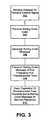
- Figure 3illustrates a method of transmitting an RF control signal in accordance with an embodiment, wherein the transmitter can be an original transmitter, trainable transmitter, trainable transceiver, or other transmitting device.
- a requestis received at the transmitter to transmit a control signal.
- a single user inputsuch as actuation of a push button or other user input device may be used to initiate an operating mode or training mode of the transmitter.
- the single user inputmay be, for example, a button press of short duration (e.g., approximately one second or less) or of a more sustained duration (e.g., greater than one second).
- Alternative duration thresholds and configurationsare contemplated.
- the single user inputmay be a combination of key presses using user input devices of the transmitter or selecting a menu item on a display.
- rolling code data(or other encryption data), control data and/or frequency data is retrieved from memory of the transmitter.
- the control circuit and/or transmitter circuit of the transmittermay be configured to retrieve encryption, control and/or frequency data from the memory of the transmitter.
- the frequency datamay include a first pre-stored frequency and a second pre-stored frequency associated with the remote system. One of the frequencies may be a preferred frequency of operation for the remote system.
- a rolling code messageis generated using the information associated with the remote system that is retrieved from memory.
- the transmittertransmits the rolling code message at a first frequency for a predetermined amount of time. In one embodiment, a counter may be used to track the length of time the rolling code message is transmitted at the first frequency.
- the first frequencymay be a preferred frequency of operation for the remote system.
- the same rolling code messageis transmitted at a second frequency.
- a rolling code messagemay be transmitted at 315 MHz for a predetermined time such as four (4) seconds and then, upon expiration of the predetermined time, the rolling code message is transmitted at 390 MHz.
- the same rolling code signal or messagemay comprise the same rolling code in both transmissions, or alternatively may comprise two different rolling codes having the same rolling code format (the format being defined by the garage door opener manufacturer). While Figure 3 illustrates an operating mode, the steps may also be performed during a training mode.
- FIG 4is a schematic block diagram of a wireless control system including a trainable transmitter in accordance with an embodiment.
- a trainable transmitter 402is shown.
- Trainable transmitter 402includes a user input device 410, a receiver circuit 404 and a transmitter circuit 414.
- Trainable transmitter 402is trainable or configurable by a user to activate one or more remote systems, e.g., remote system 408, using different radio frequency control signals.
- trainable transmitter 402may be a HomeLink® trainable transmitter manufactured by Johnson Controls Interiors, LLC, Holland, Michigan. Trainable transmitter 402 may operate, for example, as shown in any one of U.S. Patent Nos.
- Trainable transmitter 402may be a hand-held transmitter or can be integrated into or coupled to a vehicle interior element such as a visor, an overhead compartment, an instrument panel, a seat, a center console, a door panel, etc.
- remote system 408is configured to operate at two frequencies, a first frequency and a second frequency, and trainable transmitter 402 is configured to operate at one of the first frequency and the second frequency.
- Trainable transmitter 402may be trained using original transmitter 406. Trainable transmitter 402 and original transmitter 406 are brought within range of each other.
- a user input device 410 of trainable transmitter 402is actuated to place trainable transmitter 402 in a training mode. For example, a user may press a push button on trainable transmitter 402.
- a user input device 412 of the original transmitter 406is actuated to transmit an RF control signal, for example, a rolling code signal.
- a usermay press a push button on original transmitter 406.
- Original transmitter 406is configured, in response to the single user input, to transmit a rolling code control signal at the first frequency and the second frequency at which the remote system 408 operates.
- original transmitter 406transmits the rolling code control signal at the first frequency for a predetermined amount of time. Upon expiration of the predetermined amount of time, the original transmitter 406 transmits the same rolling code control signal at the second frequency. Trainable transmitter receives the rolling code control signal at the frequency at which it is configured to operate, for example, the second frequency. Trainable transmitter 402 may then identify the carrier frequency, control data and/or encryption algorithm associated with the original transmitter 406 (and remote system 408) based on the rolling code control signal received from the original transmitter 406. The identified carrier frequency, control data and/or encryption algorithm may then be stored in memory (not shown) and associated with a particular user input device 410 (e.g., a push button) of the trainable transmitter 402. Once trained, a user may transmit an RF control signal to remote system 408 by pressing the appropriate user input device 410 of trainable transmitter 402.
- a particular user input device 410e.g., a push button
- trainable transmitter 402may not compatible with the first frequency (e.g., 800 MHz) but is compatible with the second frequency (e.g., 390 MHz)
- original transmitter 406may transmit the fixed code at the first frequency followed by the second frequency.
- Trainable transmitter 402may receive the second frequency and train to the fixed code at that second frequency.
- Remote system 408may be compatible with both first and second frequencies in this embodiment.
Landscapes
- Engineering & Computer Science (AREA)
- Computer Networks & Wireless Communication (AREA)
- Physics & Mathematics (AREA)
- General Physics & Mathematics (AREA)
- Selective Calling Equipment (AREA)
Description
- The present invention relates generally to the field of RF transmitters and more particularly to a transmitter and method for transmitting an RF control signal at multiple frequencies.
- Wireless control systems are used in many different applications to provide a method of remote control of devices or systems. Wireless control systems, such as garage door opener systems, home security systems, gate controllers, etc., typically employ a portable, hand-held transmitter (i.e., an original transmitter) to transmit a control signal to a receiver located at a remote system or device. For example, a garage door opener system typically includes a receiver located within a home owner's garage and coupled to the garage door opener. A user presses a button on the original transmitter to transmit a radio frequency signal to the receiver to activate the garage door opener to open and close a garage door. Accordingly, the receiver is tuned to the frequency of its associated original transmitter and demodulates a predetermined code programmed into the original transmitter and the receiver for operating the garage door.
- To enhance security of wireless control systems, such as a garage door opener system, manufacturers commonly use encryption technology to encrypt the radio frequency signal sent from a transmitter to a receiver. One such encryption method is a rolling code system, where each digital message sent from the transmitter to the receiver has a different code from the previous digital message. In one such system, a transmitter identifier (sometimes called a serial number) and an encrypted counter value (sometimes called a hop code) are sent with each transmission. A counter value in the transmitter increments each time the transmitter button is pressed. An encryption algorithm encrypts the counter value to create a new encrypted code or value. When the encrypted counter value is transmitted, it appears to bear no predictable relationship to the previously sent encrypted counter value, and thereby appears to "hop" from one value to another. The receiver also stores the counter value in unencrypted form. Upon receipt of an encrypted counter value for a particular transmitter identifier, the counter value is unencrypted and compared to the previously stored counter value to determine whether the garage door opener should be activated. If the new value is less than or the same as the previously stored counter value, it may have come from a code grabber, and, therefore, the receiver does not activate the garage door opener. If the new value is greater than the previously stored counter value but less than a predefined number, the garage door is activated. If the new value is greater than the predefined number ahead of the previously stored counter value, the receiver stores the value, but does not activate the garage door opener. Upon receipt of the next counter value from the transmitter, if the receiver determines that the two values are in sequence, the garage door is activated and the most recently received counter value is stored in memory. The system described above is just one example of many types of rolling code based systems.
- As an alternative to a portable, hand-held original transmitter, a trainable (or universal) transmitter or transceiver may be provided in, for example, a vehicle, for use with remote control devices or systems. An example of a trainable or universal transmitter is the HomeLink® trainable transmitter manufactured by Johnson Controls Interiors, LLC, Holland, Michigan. A trainable transmitter may be configurable by a user to activate one or more of a plurality of different receivers using different radio frequency messages. In one example, a trainable transmitter may be trained to an existing original transmitter for a wireless control system by holding the two transmitters in close range and pressing buttons on the original transmitter and trainable transmitter simultaneously. The trainable transmitter identifies the type of wireless control system associated with the original transmitter based on the radio frequency signal received from the original transmitter. The trainable transmitter may then identify and store the control data and RF carrier frequency of the original transmitter radio frequency control signal. For systems employing a rolling code (or other encryption method), the trainable transmitter and wireless control system receiver are then synchronized so that, for example, the counters of the trainable transmitter and the receiver begin at the same value. Once trained, the trainable transmitter may be used to transmit RF signals to the receiver to control the wireless control system such trainable transceiver is disclosed by
GB 2315892 - An original transmitter or trainable transmitter is configured to send a control signal at the frequency to which the receiver of a wireless control system is tuned. If, however, a wireless control system is dual- or multiple-frequency (i.e., capable of operating at one of multiple frequencies), it is possible that certain existing trainable transmitters or receivers may not be compatible with one or more of the operating frequencies of the wireless control system. Such a problem may also occur when a manufacturer of a wireless control system changes the frequency of operation for new versions of the wireless control system. Accordingly, there is a need for a transmitter that is capable of transmitting an RF control signal at two frequencies in response to a single user input. Further, there is a need for a transmitter that is configured to, in response to a single user input, transmit a rolling code message at a first frequency and to transmit the same rolling code message at a second frequency.
- In accordance with an embodiment, a transmitter for transmitting an RF control signal to a remote system includes a user input device, a memory having control data associated with the remote device including a first frequency and a second frequency, and a transmitter circuit coupled to the user input device and memory, the transmitter circuit configured to, in response to a single user input, generate a rolling code signal, to transmit the rolling code signal at the first frequency for a predetermined amount of time, and, upon expiration of the predetermined amount of time, to transmit the rolling code signal at the second frequency.
- In accordance with another embodiment, a method for transmitting an RF control signal to a remote system includes receiving a single user input to request transmission of an RF control signal, generating a rolling code signal based on control data associated with the remote system in response to the single user input, the control data including a first frequency and a second frequency, transmitting the rolling code signal at the first frequency for a predetermined amount of time, and upon expiration of the predetermined amount of time, transmitting the rolling code signal at the second frequency.
- The invention will be more readily understood by reference to the following description taken with the accompanying drawings, in which:
FIG. 1 is a schematic block diagram of a wireless control system in accordance with an embodiment.FIG. 2 is a block diagram of a transmitter in accordance with an exemplary embodiment.FIG. 3 illustrates a method for transmitting an RF control signal in accordance with an embodiment.FIG. 4 is a schematic block diagram of a wireless control signal including a trainable transmitter in accordance with an embodiment.Figure 1 is a schematic block diagram of a wireless control system in accordance with an embodiment.Wireless control system 100 includes atransmitter 102 and aremote system 104.Transmitter 102 is a radio frequency transmitter configured to send wireless radio frequency messages to areceiver 106 of theremote system 104 to activateremote system 104.Transmitter 102 may be, for example, an original transmitter forwireless control system 100, a trainable transmitter or a trainable transceiver. An original transmitter is a transmitter, typically a hand-held transmitter, which is sold withremote system 104 or as an after market item, and which is configured to transmit an activation signal at a predetermined carrier frequency and having control data configured to activateremote system 104. A trainable transmitter or transceiver may be configurable by a user to activate one or more of a plurality of different receivers and associated remote systems using different radio frequency messages. A trainable transmitter or transceiver may be, for example, mounted in a vehicle and coupled to a vehicle interior element such as a visor, an overhead compartment, an instrument panel, a seat, a center console, a door panel or any other vehicle interior element. Alternatively, a trainable transmitter may be embodied in a hand-held device such as a portable housing, a key fob, a key chain, etc.Remote system 104 may be, for example, a garage door opener, a gate opener or operator, a home alarm system, a home lighting system, a heating ventilation air conditioning (HVAC) system, a deadbolt door lock or entry door lock system, a home appliance, a remote keyless entry (RKE) system for an automobile, or other security or access-control system for residential and/or commercial applications.Remote system 104 includes or is coupled to areceiver 106 and an antenna (not shown) for receiving radio frequency messages including control data to controlremote system 104. Each radio frequency control signal or message transmitted bytransmitter 102 may be configured to activateremote system 104 viareceiver 106 to causeremote system 104 to take some action, to synchronize, to arm or disarm a security system, to open a garage door or gate, to lock or unlock a deadbolt lock system, to lock or unlock a vehicle RKE system, to create a panic/alarm condition at a vehicle, or to cause some other function or effect.Transmitter 102 includes a user input device 110 which may be, for example, a push button switch, a dial, knobs, a touch-screen display, a voice or speech-recognition system (e.g., a voice actuated input control circuit configured to receive voice signals from a user), or a biometric scanning device for improved security (e.g., a fingerprint scanner).Transmitter 102 andreceiver 106 may include digital and/or analog circuitry to perform the functions described herein and may include, for example, one or more microprocessors, microcontrollers, application-specific integrated circuits, volatile and/or non-volatile memory and radio frequency transmit and/or receive components, such as transistors, inductors, antennas, etc. In one embodiment,transmitter 102 andreceiver 106 communicate using encryption technology, for example, a rolling or variable code. Any of a variety of rolling code or non-rolling code encryption algorithms may be used, including those implemented in remote keyless entry systems and garage door opener systems.- In response to a single user input received via user input device 110 (e.g., a single button press),
transmitter 102 is configured to generate and transmit an encrypted (e.g., rolling code) message. In particular, in response to the single user input,transmitter 102 is configured to generate and transmit an encrypted message at a first frequency for a predetermined period of time. Upon expiration of the predetermined period of time,transmitter 102 transmits the same encrypted message at a second frequency. The first and second frequencies may be associated with theremote system 104 andreceiver 106.Receiver 106 may be configured to receive either of the first and second frequencies or only one of the first and second frequencies.Figure 2 is a schematic block diagram of a transmitter in accordance with an embodiment.Transmitter 200 includes atransmitter circuit 204 that is coupled to anantenna 202. In an alternative embodiment, a single dual function transceiver having transmit and receive circuitry may be provided in place oftransmitter circuit 204. As mentioned above,transmitter 200 may be, for example, an original transmitter or a trainable transmitter.Transmitter 200 may be trainable by way of receiving a signal from an original transmitter, by receiving user inputs for training, or by guessing a plurality of possible signals corresponding toreceiver 106. Transmitter circuit 204 is also coupled to acontrol circuit 206.Control circuit 206 may include various types of control circuitry, digital and/or analog, and may include a microprocessor, microcontroller, application specific integrated circuit (ASIC), or other digital and/or analog circuitry configured to perform various input/output, control, analysis, and other functions to be described herein.Control circuit 206 is coupled to user input device(s) 210 and amemory 208. User input device(s) 210 may be, for example, push buttons, switches, knobs, dials, voice actuated input, etc.Memory 208 includes volatile and/or non-volatile memory to, for example, store a computer program or other software to perform the functions described herein.Memory 208 is also configured to store information such as control data, carrier frequencies, and/or rolling code or other encryption algorithms associated with a remote system or systems. In one embodiment, the control data, frequency data and encryption algorithms are pre-stored inmemory 208. In an alternative embodiment, the control data and frequency data may be learned and then stored inmemory 208. At least one remote system for which information is stored inmemory 208 may have more than one frequency of operation. For example, a remote system may have a first frequency of operation and a second frequency of operation. Both the first and second frequencies associated with the particular remote system are stored inmemory 208. User input device(s) 210 may comprise any number of user input devices, which may each be configured during a training mode or during manufacture to transmit a different control signal based on data stored inmemory 208 and/or learned during a training operation.Transmitter circuit 204 communicates with a remote system viaantenna 202. In response to a single user input via user input device(s) 210 (e.g., a push button),transmitter circuit 204 is configured, under control fromcontrol circuit 206, to generate and transmit a control signal using carrier frequency, control data and/or encryption algorithm information associated with a particular remote system.Figure 3 illustrates a method of transmitting an RF control signal in accordance with an embodiment, wherein the transmitter can be an original transmitter, trainable transmitter, trainable transceiver, or other transmitting device. Atblock 302, a request is received at the transmitter to transmit a control signal. For example, a single user input such as actuation of a push button or other user input device may be used to initiate an operating mode or training mode of the transmitter. The single user input may be, for example, a button press of short duration (e.g., approximately one second or less) or of a more sustained duration (e.g., greater than one second). Alternative duration thresholds and configurations are contemplated. In alternative embodiments, the single user input may be a combination of key presses using user input devices of the transmitter or selecting a menu item on a display.- At
block 304, rolling code data (or other encryption data), control data and/or frequency data is retrieved from memory of the transmitter. For example, the control circuit and/or transmitter circuit of the transmitter may be configured to retrieve encryption, control and/or frequency data from the memory of the transmitter. The frequency data may include a first pre-stored frequency and a second pre-stored frequency associated with the remote system. One of the frequencies may be a preferred frequency of operation for the remote system. Atblock 306, a rolling code message is generated using the information associated with the remote system that is retrieved from memory. Atblock 308, the transmitter transmits the rolling code message at a first frequency for a predetermined amount of time. In one embodiment, a counter may be used to track the length of time the rolling code message is transmitted at the first frequency. The first frequency may be a preferred frequency of operation for the remote system. Upon expiration of the predetermined time, at block 310, the same rolling code message is transmitted at a second frequency. For example, a rolling code message may be transmitted at 315 MHz for a predetermined time such as four (4) seconds and then, upon expiration of the predetermined time, the rolling code message is transmitted at 390 MHz. The same rolling code signal or message may comprise the same rolling code in both transmissions, or alternatively may comprise two different rolling codes having the same rolling code format (the format being defined by the garage door opener manufacturer). WhileFigure 3 illustrates an operating mode, the steps may also be performed during a training mode. Figure 4 is a schematic block diagram of a wireless control system including a trainable transmitter in accordance with an embodiment. InFigure 4 , atrainable transmitter 402 is shown.Trainable transmitter 402 includes a user input device 410, areceiver circuit 404 and atransmitter circuit 414.Trainable transmitter 402 is trainable or configurable by a user to activate one or more remote systems, e.g.,remote system 408, using different radio frequency control signals. In one exemplary embodiment,trainable transmitter 402 may be a HomeLink® trainable transmitter manufactured by Johnson Controls Interiors, LLC, Holland, Michigan.Trainable transmitter 402 may operate, for example, as shown in any one ofU.S. Patent Nos. 5,686,903 ,5,661,804 or5,614,891 , which are incorporated by reference herein in their entirety.Trainable transmitter 402 may be a hand-held transmitter or can be integrated into or coupled to a vehicle interior element such as a visor, an overhead compartment, an instrument panel, a seat, a center console, a door panel, etc. In an embodiment,remote system 408 is configured to operate at two frequencies, a first frequency and a second frequency, andtrainable transmitter 402 is configured to operate at one of the first frequency and the second frequency.Trainable transmitter 402 may be trained usingoriginal transmitter 406.Trainable transmitter 402 andoriginal transmitter 406 are brought within range of each other. A user input device 410 oftrainable transmitter 402 is actuated to placetrainable transmitter 402 in a training mode. For example, a user may press a push button ontrainable transmitter 402. In addition, a user input device 412 of theoriginal transmitter 406 is actuated to transmit an RF control signal, for example, a rolling code signal. For example, a user may press a push button onoriginal transmitter 406.Original transmitter 406 is configured, in response to the single user input, to transmit a rolling code control signal at the first frequency and the second frequency at which theremote system 408 operates. In particular,original transmitter 406 transmits the rolling code control signal at the first frequency for a predetermined amount of time. Upon expiration of the predetermined amount of time, theoriginal transmitter 406 transmits the same rolling code control signal at the second frequency. Trainable transmitter receives the rolling code control signal at the frequency at which it is configured to operate, for example, the second frequency.Trainable transmitter 402 may then identify the carrier frequency, control data and/or encryption algorithm associated with the original transmitter 406 (and remote system 408) based on the rolling code control signal received from theoriginal transmitter 406. The identified carrier frequency, control data and/or encryption algorithm may then be stored in memory (not shown) and associated with a particular user input device 410 (e.g., a push button) of thetrainable transmitter 402. Once trained, a user may transmit an RF control signal toremote system 408 by pressing the appropriate user input device 410 oftrainable transmitter 402.- While the exemplary embodiments illustrated in the FIGS. and described above are presently preferred, it should be understood that these embodiments are offered by way of example only. Accordingly, the present invention is not limited to a particular embodiment, but extends to various modifications that nevertheless fall within the scope of the appended claims. The order or sequence of any process or method steps may be varied or re-sequenced according to alternative embodiments. According to one alternative embodiment, the system and method of
Figure 3 may be modified to transmit a fixed code (e.g., dip switch-based, "billion code" based, etc.) at the first and second frequencies instead of (or in addition to) the rolling code. For example, wheretrainable transmitter 402 is not compatible with the first frequency (e.g., 800 MHz) but is compatible with the second frequency (e.g., 390 MHz),original transmitter 406 may transmit the fixed code at the first frequency followed by the second frequency.Trainable transmitter 402 may receive the second frequency and train to the fixed code at that second frequency.Remote system 408 may be compatible with both first and second frequencies in this embodiment.
Claims (9)
- A system comprising a transmitter (102), a remote system and a trainable transceiver, wherein the transmitter transmits a RF control signal to a remote system and the transmitter (102) comprises:a user input device;a memory (208) having control data associated with the remote system including a first frequency and a second frequency; anda transmitter circuit (204) coupled to the user input device and memory, the transmitter circuit configured to, in response to a single user input, generate a rolling code signal (306), to transmit the rolling code signal at the first frequency for a predetermined amount of time (308), and, upon expiration of the predetermined amount of time, to transmit the rolling code signal at the second frequency (310);
characterized in, that
the first frequency is a preferred frequency of operation of the remote system but is not compatible with the trainable transceiver configured to learn to transmit to the remote system, and wherein the second frequency is compatible with the trainable transceiver. - A system according to claim 1, wherein the control data further includes a rolling code encryption algorithm.
- A system according to claim 1, wherein the transmitter is an original transmitter associated with the remote system.
- A system according to claim 1, wherein the user input device is a push button.
- A system according to claim 4, wherein the single user input is a button press.
- A system according to claim 1, further comprising a control circuit coupled to the user input device, memory and transmitter circuit, the control circuit configured to retrieve the control data from memory and to provide the control data to the transmitter circuit.
- A method for transmitting an RF control signal to a remote system, the method comprising:receiving a single user input to request transmission of an RF control signal;generating a rolling code signal (306) based on control data associated with the remote system in response to the single user input, the control data including a first frequency and a second frequency;transmitting the rolling code signal at the first frequency for a predetermined amount of time (308); andupon expiration of the predetermined amount of time, transmitting the rolling code signal at the second frequency (310);
characterized in, that
the first frequency is a preferred frequency of operation of the remote system but is not compatible with a trainable transceiver configured to learn to transmit to the remote system, and wherein the second frequency is compatible with the trainable transceiver. - A method according to claim 7, wherein the control data further includes a rolling code encryption algorithm.
- A method according to claim 7, wherein the single user input is a button press.
Applications Claiming Priority (2)
| Application Number | Priority Date | Filing Date | Title |
|---|---|---|---|
| US11/324,745US8384513B2 (en) | 2006-01-03 | 2006-01-03 | Transmitter and method for transmitting an RF control signal |
| PCT/US2006/049646WO2007081586A1 (en) | 2006-01-03 | 2006-12-29 | Transmitter and method for transmitting an rf control signal |
Publications (2)
| Publication Number | Publication Date |
|---|---|
| EP1971972A1 EP1971972A1 (en) | 2008-09-24 |
| EP1971972B1true EP1971972B1 (en) | 2014-06-04 |
Family
ID=38042517
Family Applications (1)
| Application Number | Title | Priority Date | Filing Date |
|---|---|---|---|
| EP06848381.7AActiveEP1971972B1 (en) | 2006-01-03 | 2006-12-29 | System and method for transmitting an rf control signal |
Country Status (4)
| Country | Link |
|---|---|
| US (1) | US8384513B2 (en) |
| EP (1) | EP1971972B1 (en) |
| CN (2) | CN101390138A (en) |
| WO (1) | WO2007081586A1 (en) |
Families Citing this family (48)
| Publication number | Priority date | Publication date | Assignee | Title |
|---|---|---|---|---|
| US8330569B2 (en)* | 2003-05-28 | 2012-12-11 | Johnson Controls Technology Company | System and method for receiving data for training a trainable transmitter |
| US7922086B2 (en) | 2004-09-30 | 2011-04-12 | The Invention Science Fund I, Llc | Obtaining user assistance |
| US10687166B2 (en) | 2004-09-30 | 2020-06-16 | Uber Technologies, Inc. | Obtaining user assistance |
| US10445799B2 (en) | 2004-09-30 | 2019-10-15 | Uber Technologies, Inc. | Supply-chain side assistance |
| US10514816B2 (en) | 2004-12-01 | 2019-12-24 | Uber Technologies, Inc. | Enhanced user assistance |
| US8384513B2 (en) | 2006-01-03 | 2013-02-26 | Johnson Controls Technology Company | Transmitter and method for transmitting an RF control signal |
| US8180293B2 (en) | 2006-03-24 | 2012-05-15 | The Invention Science Fund I, Llc | Vehicle control and communication via device in proximity |
| US8358976B2 (en) | 2006-03-24 | 2013-01-22 | The Invention Science Fund I, Llc | Wireless device with an aggregate user interface for controlling other devices |
| US8126400B2 (en)* | 2006-03-24 | 2012-02-28 | The Invention Science Fund I, Llc | Method for an aggregate user interface for controlling other devices |
| US8538331B2 (en)* | 2006-03-24 | 2013-09-17 | The Invention Science Fund I, LC | Vehicle control and communication via device in proximity |
| US8195106B2 (en)* | 2006-05-31 | 2012-06-05 | The Invention Science Fund I, Llc | Vehicle control and communication via device in proximity |
| WO2008105944A2 (en)* | 2006-09-29 | 2008-09-04 | Linx Technologies, Inc. | Encoder and decoder apparatus and methods |
| PL2092275T3 (en)* | 2006-12-20 | 2013-03-29 | Johnson Controls Tech Co | System and method for providing route calculation and information to a vehicle |
| EP2091784B1 (en) | 2006-12-20 | 2012-02-01 | Johnson Controls Technology Company | Remote display reproduction system and method |
| WO2008091727A1 (en)* | 2007-01-23 | 2008-07-31 | Johnson Controls Technology Company | Mobile device gateway systems and methods |
| US8198988B2 (en)* | 2007-11-16 | 2012-06-12 | Sony Corporation | Secure link between controller and device |
| WO2009073806A2 (en) | 2007-12-05 | 2009-06-11 | Johnson Controls Technology Company | Vehicle user interface systems and methods |
| US9324230B2 (en) | 2008-12-04 | 2016-04-26 | Gentex Corporation | System and method for configuring a wireless control system of a vehicle using induction field communication |
| DE102008001555A1 (en)* | 2008-05-05 | 2009-11-12 | Robert Bosch Gmbh | Procedure for submitting at least one date |
| US8581695B2 (en)* | 2009-05-27 | 2013-11-12 | Grant B. Carlson | Channel-switching remote controlled barrier opening system |
| WO2010138118A1 (en)* | 2009-05-27 | 2010-12-02 | Overhead Door Corporation | Channel switching remote controlled barrier opening system |
| US9819498B2 (en) | 2010-02-04 | 2017-11-14 | Gentex Corporation | System and method for wireless re-programming of memory in a communication system |
| CN101931523A (en)* | 2010-05-10 | 2010-12-29 | 胡章儒 | Inversed chip-stage decoding time synchronization rolling codes |
| WO2012103394A1 (en) | 2011-01-28 | 2012-08-02 | Johnson Controls Technology Company | Wireless trainable transceiver device with integrated interface and gps modules |
| CN102708665B (en)* | 2012-06-04 | 2014-05-28 | 深圳市励创微电子有限公司 | Broadband code signal detection circuit and wireless remote signal decoding circuit thereof |
| US9316038B2 (en) | 2013-03-15 | 2016-04-19 | Overhead Door Corporation | Factory programming of paired authorization codes in wireless transmitter and door operator |
| US20140266583A1 (en)* | 2013-03-15 | 2014-09-18 | Keylessride | Capturing Code Sequences |
| US9873387B2 (en)* | 2013-12-27 | 2018-01-23 | Huf North America Automotive Parts Mfg. Corp. | Vehicle closure release with attached deployable camera |
| US10458801B2 (en) | 2014-05-06 | 2019-10-29 | Uber Technologies, Inc. | Systems and methods for travel planning that calls for at least one transportation vehicle unit |
| US11100434B2 (en) | 2014-05-06 | 2021-08-24 | Uber Technologies, Inc. | Real-time carpooling coordinating system and methods |
| US9552559B2 (en) | 2014-05-06 | 2017-01-24 | Elwha Llc | System and methods for verifying that one or more directives that direct transport of a second end user does not conflict with one or more obligations to transport a first end user |
| US9483744B2 (en) | 2014-05-06 | 2016-11-01 | Elwha Llc | Real-time carpooling coordinating systems and methods |
| WO2016042509A1 (en)* | 2014-09-19 | 2016-03-24 | Silca S.P.A. | Method for creating of an improved rolling code radio control |
| CN104283674A (en)* | 2014-10-27 | 2015-01-14 | 北海市蕴芯电子科技有限公司 | TTF RFID with both rolling code and secret key encrypted |
| WO2016134158A1 (en) | 2015-02-20 | 2016-08-25 | Gentex Corporation | Resistor multiplexed switch wake-up circuit |
| RU2702848C2 (en)* | 2015-03-10 | 2019-10-11 | Кейм С.п.А. | Radio control panel for electric devices and method of transmitting command to electric device |
| EP3555872B1 (en)* | 2017-02-06 | 2021-03-31 | Gentex Corporation | Selective transmission of commands associated with a single transceiver channel |
| WO2018148577A2 (en)* | 2017-02-10 | 2018-08-16 | Gentex Corporation | Training and controlling multiple functions of a remote device with a single channel of a trainable transceiver |
| US10652743B2 (en) | 2017-12-21 | 2020-05-12 | The Chamberlain Group, Inc. | Security system for a moveable barrier operator |
| US10682983B2 (en) | 2018-01-05 | 2020-06-16 | Voxx International Corporation | Device for secure tire and wheel protection |
| US10424193B1 (en)* | 2018-04-10 | 2019-09-24 | Gentex Corporation | Locking mechanisms for enabling or disabling the operations of trainable transceivers |
| US11074773B1 (en) | 2018-06-27 | 2021-07-27 | The Chamberlain Group, Inc. | Network-based control of movable barrier operators for autonomous vehicles |
| CA3107457A1 (en) | 2018-08-01 | 2020-02-06 | The Chamberlain Group, Inc. | Movable barrier operator and transmitter pairing over a network |
| US11220856B2 (en) | 2019-04-03 | 2022-01-11 | The Chamberlain Group Llc | Movable barrier operator enhancement device and method |
| US10997810B2 (en) | 2019-05-16 | 2021-05-04 | The Chamberlain Group, Inc. | In-vehicle transmitter training |
| US11423761B2 (en) | 2019-10-29 | 2022-08-23 | Gentex Corporation | Connected monitoring system |
| CA3182192A1 (en) | 2021-11-24 | 2023-05-24 | Gmi Holdings, Inc. | Multi-channel signaling for a barrier operator system |
| DE102022120733B3 (en)* | 2022-08-17 | 2023-12-07 | Hörmann KG Antriebstechnik | Method for remotely controlling an automatic building or fencing lock, radio remote control transmitter therefor, building or fencing locking system and computer program |
Family Cites Families (33)
| Publication number | Priority date | Publication date | Assignee | Title |
|---|---|---|---|---|
| DE4308441A1 (en)* | 1993-03-17 | 1994-09-22 | Thomson Brandt Gmbh | Remote control method and apparatus |
| GB2315892B (en) | 1996-07-26 | 1998-06-24 | Prince Corp | Multiple frequency transmitter |
| DE19645808B4 (en)* | 1996-11-07 | 2005-12-15 | Kiekert Ag | Motor vehicle with a central locking system and with a remote control installation |
| US6181255B1 (en)* | 1997-02-27 | 2001-01-30 | The Chamberlain Group, Inc. | Multi-frequency radio frequency transmitter with code learning capability |
| US6078271A (en)* | 1998-02-20 | 2000-06-20 | Lear Automotive Dearborn, Inc. | Multiple-frequency programmable transmitter |
| US6486795B1 (en)* | 1998-07-31 | 2002-11-26 | The Chamberlain Group, Inc. | Universal transmitter |
| US7346374B2 (en)* | 1999-05-26 | 2008-03-18 | Johnson Controls Technology Company | Wireless communications system and method |
| EP1246414B1 (en)* | 1999-05-26 | 2012-05-23 | Johnson Controls Technology Company | Wireless communications system and method therefor |
| FR2808633B1 (en)* | 2000-05-04 | 2002-07-26 | Sagem | MULTIBAND SHORT RADIO RECEIVER FOR MOTOR VEHICLE DATA |
| US20020163440A1 (en)* | 2001-03-01 | 2002-11-07 | Tsui Philip Y.W. | Programmable universal transmitter |
| US8325008B2 (en)* | 2001-04-25 | 2012-12-04 | The Chamberlain Group, Inc. | Simplified method and apparatus for programming a universal transmitter |
| US20040110472A1 (en)* | 2002-04-23 | 2004-06-10 | Johnson Controls Technology Company | Wireless communication system and method |
| US20040203379A1 (en)* | 2002-04-23 | 2004-10-14 | Johnson Controls Technology Company | Bluetooth transmission of vehicle diagnostic information |
| US7254182B2 (en)* | 2002-07-09 | 2007-08-07 | Tsui Philip Y W | Transmitter for operating multiple devices |
| WO2004034352A1 (en)* | 2002-10-08 | 2004-04-22 | Johnson Controls Technology Company | System and method for wireless control of remote electronic systems including functionality based on location |
| US7911358B2 (en)* | 2002-10-08 | 2011-03-22 | Johnson Controls Technology Company | System and method for enrollment of a remotely controlled device in a trainable transmitter |
| WO2004036526A2 (en)* | 2002-10-18 | 2004-04-29 | Johnson Controls Technology Company | System and method for receiving a wireless status signal in a vehicle from a remote electronic system |
| US8531266B2 (en)* | 2002-10-18 | 2013-09-10 | Johnson Controls Technology Company | System and method for providing an in-vehicle transmitter having multi-colored LED |
| WO2004077729A2 (en) | 2003-02-21 | 2004-09-10 | Johnson Controls Technology Company | Trainable remote controller and method for determining the frequency of a learned control signal |
| JP2006519981A (en)* | 2003-02-24 | 2006-08-31 | ジョンソン コントロールズ テクノロジー カンパニー | System and method for compensating motor magnetic disturbances in compass measurement |
| US7088218B2 (en)* | 2003-07-30 | 2006-08-08 | Lear Corporation | Wireless appliance activation transceiver |
| US7269416B2 (en)* | 2003-07-30 | 2007-09-11 | Lear Corporation | Universal vehicle based garage door opener control system and method |
| US7183940B2 (en)* | 2003-07-30 | 2007-02-27 | Lear Corporation | Radio relay appliance activation |
| US7161466B2 (en)* | 2003-07-30 | 2007-01-09 | Lear Corporation | Remote control automatic appliance activation |
| US7039397B2 (en)* | 2003-07-30 | 2006-05-02 | Lear Corporation | User-assisted programmable appliance control |
| US7183941B2 (en)* | 2003-07-30 | 2007-02-27 | Lear Corporation | Bus-based appliance remote control |
| US7068181B2 (en)* | 2003-07-30 | 2006-06-27 | Lear Corporation | Programmable appliance remote control |
| US7084781B2 (en)* | 2003-07-30 | 2006-08-01 | Lear Corporation | Programmable vehicle-based appliance remote control |
| CN100419811C (en)* | 2003-11-11 | 2008-09-17 | 浙江中控技术股份有限公司 | Infrared signal learning type control device and method |
| US7656931B2 (en)* | 2003-12-31 | 2010-02-02 | Ut-Battelle, Llc | Hybrid spread spectrum radio system |
| US7864070B2 (en)* | 2005-03-22 | 2011-01-04 | Johnson Controls Technology Company | System and method for training a trainable transmitter |
| US7786843B2 (en)* | 2005-04-19 | 2010-08-31 | Johnson Controls Technology Company | System and method for training a trainable transmitter and a remote control system receiver |
| US8384513B2 (en) | 2006-01-03 | 2013-02-26 | Johnson Controls Technology Company | Transmitter and method for transmitting an RF control signal |
- 2006
- 2006-01-03USUS11/324,745patent/US8384513B2/enactiveActive
- 2006-12-29EPEP06848381.7Apatent/EP1971972B1/enactiveActive
- 2006-12-29CNCNA200680053389XApatent/CN101390138A/enactivePending
- 2006-12-29WOPCT/US2006/049646patent/WO2007081586A1/enactiveApplication Filing
- 2006-12-29CNCN201010213112.7Apatent/CN101872542B/enactiveActive
Also Published As
| Publication number | Publication date |
|---|---|
| CN101390138A (en) | 2009-03-18 |
| US20070152798A1 (en) | 2007-07-05 |
| US8384513B2 (en) | 2013-02-26 |
| CN101872542A (en) | 2010-10-27 |
| WO2007081586A1 (en) | 2007-07-19 |
| CN101872542B (en) | 2013-06-12 |
| EP1971972A1 (en) | 2008-09-24 |
Similar Documents
| Publication | Publication Date | Title |
|---|---|---|
| EP1971972B1 (en) | System and method for transmitting an rf control signal | |
| EP1875333B1 (en) | System and method for training a trainable transmitter and a remote control system receiver | |
| US8138883B2 (en) | System and method of training a transmit/receive system | |
| EP1864269B1 (en) | System and method for training a trainable transmitter | |
| EP2078291B1 (en) | System and method for training a trainable transmitter | |
| US8253528B2 (en) | Trainable transceiver system | |
| US8174357B2 (en) | System and method for training a transmitter to control a remote control system | |
| EP1872350B1 (en) | System and method for determining a receiver threshold for a trainable transmitter system | |
| US6377173B1 (en) | Garage door opener signal incorporated into vehicle key/fob combination | |
| EP1057152B1 (en) | Multiple-frequency programmable transmitter | |
| EP1629450B1 (en) | System and method for training a transmitter to control a remote control system |
Legal Events
| Date | Code | Title | Description |
|---|---|---|---|
| PUAI | Public reference made under article 153(3) epc to a published international application that has entered the european phase | Free format text:ORIGINAL CODE: 0009012 | |
| 17P | Request for examination filed | Effective date:20080804 | |
| AK | Designated contracting states | Kind code of ref document:A1 Designated state(s):AT BE BG CH CY CZ DE DK EE ES FI FR GB GR HU IE IS IT LI LT LU LV MC NL PL PT RO SE SI SK TR | |
| 17Q | First examination report despatched | Effective date:20100716 | |
| DAX | Request for extension of the european patent (deleted) | ||
| GRAP | Despatch of communication of intention to grant a patent | Free format text:ORIGINAL CODE: EPIDOSNIGR1 | |
| INTG | Intention to grant announced | Effective date:20131216 | |
| GRAS | Grant fee paid | Free format text:ORIGINAL CODE: EPIDOSNIGR3 | |
| GRAA | (expected) grant | Free format text:ORIGINAL CODE: 0009210 | |
| AK | Designated contracting states | Kind code of ref document:B1 Designated state(s):AT BE BG CH CY CZ DE DK EE ES FI FR GB GR HU IE IS IT LI LT LU LV MC NL PL PT RO SE SI SK TR | |
| REG | Reference to a national code | Ref country code:GB Ref legal event code:FG4D | |
| REG | Reference to a national code | Ref country code:CH Ref legal event code:EP | |
| REG | Reference to a national code | Ref country code:AT Ref legal event code:REF Ref document number:671442 Country of ref document:AT Kind code of ref document:T Effective date:20140615 | |
| REG | Reference to a national code | Ref country code:IE Ref legal event code:FG4D | |
| REG | Reference to a national code | Ref country code:DE Ref legal event code:R096 Ref document number:602006041834 Country of ref document:DE Effective date:20140717 | |
| RAP2 | Party data changed (patent owner data changed or rights of a patent transferred) | Owner name:GENTEX CORPORATION | |
| REG | Reference to a national code | Ref country code:DE Ref legal event code:R081 Ref document number:602006041834 Country of ref document:DE Owner name:GENTEX CORPORATION, ZEELAND, US Free format text:FORMER OWNER: JOHNSON CONTROLS TECHNOLOGY CO., HOLLAND, MICH., US Effective date:20140826 | |
| REG | Reference to a national code | Ref country code:AT Ref legal event code:MK05 Ref document number:671442 Country of ref document:AT Kind code of ref document:T Effective date:20140604 | |
| REG | Reference to a national code | Ref country code:NL Ref legal event code:VDEP Effective date:20140604 | |
| PG25 | Lapsed in a contracting state [announced via postgrant information from national office to epo] | Ref country code:LT Free format text:LAPSE BECAUSE OF FAILURE TO SUBMIT A TRANSLATION OF THE DESCRIPTION OR TO PAY THE FEE WITHIN THE PRESCRIBED TIME-LIMIT Effective date:20140604 Ref country code:GR Free format text:LAPSE BECAUSE OF FAILURE TO SUBMIT A TRANSLATION OF THE DESCRIPTION OR TO PAY THE FEE WITHIN THE PRESCRIBED TIME-LIMIT Effective date:20140905 Ref country code:FI Free format text:LAPSE BECAUSE OF FAILURE TO SUBMIT A TRANSLATION OF THE DESCRIPTION OR TO PAY THE FEE WITHIN THE PRESCRIBED TIME-LIMIT Effective date:20140604 Ref country code:CY Free format text:LAPSE BECAUSE OF FAILURE TO SUBMIT A TRANSLATION OF THE DESCRIPTION OR TO PAY THE FEE WITHIN THE PRESCRIBED TIME-LIMIT Effective date:20140604 | |
| REG | Reference to a national code | Ref country code:LT Ref legal event code:MG4D | |
| PG25 | Lapsed in a contracting state [announced via postgrant information from national office to epo] | Ref country code:SE Free format text:LAPSE BECAUSE OF FAILURE TO SUBMIT A TRANSLATION OF THE DESCRIPTION OR TO PAY THE FEE WITHIN THE PRESCRIBED TIME-LIMIT Effective date:20140604 Ref country code:AT Free format text:LAPSE BECAUSE OF FAILURE TO SUBMIT A TRANSLATION OF THE DESCRIPTION OR TO PAY THE FEE WITHIN THE PRESCRIBED TIME-LIMIT Effective date:20140604 Ref country code:LV Free format text:LAPSE BECAUSE OF FAILURE TO SUBMIT A TRANSLATION OF THE DESCRIPTION OR TO PAY THE FEE WITHIN THE PRESCRIBED TIME-LIMIT Effective date:20140604 | |
| PG25 | Lapsed in a contracting state [announced via postgrant information from national office to epo] | Ref country code:RO Free format text:LAPSE BECAUSE OF FAILURE TO SUBMIT A TRANSLATION OF THE DESCRIPTION OR TO PAY THE FEE WITHIN THE PRESCRIBED TIME-LIMIT Effective date:20140604 Ref country code:SK Free format text:LAPSE BECAUSE OF FAILURE TO SUBMIT A TRANSLATION OF THE DESCRIPTION OR TO PAY THE FEE WITHIN THE PRESCRIBED TIME-LIMIT Effective date:20140604 Ref country code:CZ Free format text:LAPSE BECAUSE OF FAILURE TO SUBMIT A TRANSLATION OF THE DESCRIPTION OR TO PAY THE FEE WITHIN THE PRESCRIBED TIME-LIMIT Effective date:20140604 Ref country code:PT Free format text:LAPSE BECAUSE OF FAILURE TO SUBMIT A TRANSLATION OF THE DESCRIPTION OR TO PAY THE FEE WITHIN THE PRESCRIBED TIME-LIMIT Effective date:20141006 Ref country code:ES Free format text:LAPSE BECAUSE OF FAILURE TO SUBMIT A TRANSLATION OF THE DESCRIPTION OR TO PAY THE FEE WITHIN THE PRESCRIBED TIME-LIMIT Effective date:20140604 Ref country code:EE Free format text:LAPSE BECAUSE OF FAILURE TO SUBMIT A TRANSLATION OF THE DESCRIPTION OR TO PAY THE FEE WITHIN THE PRESCRIBED TIME-LIMIT Effective date:20140604 | |
| PG25 | Lapsed in a contracting state [announced via postgrant information from national office to epo] | Ref country code:IS Free format text:LAPSE BECAUSE OF FAILURE TO SUBMIT A TRANSLATION OF THE DESCRIPTION OR TO PAY THE FEE WITHIN THE PRESCRIBED TIME-LIMIT Effective date:20141004 Ref country code:NL Free format text:LAPSE BECAUSE OF FAILURE TO SUBMIT A TRANSLATION OF THE DESCRIPTION OR TO PAY THE FEE WITHIN THE PRESCRIBED TIME-LIMIT Effective date:20140604 Ref country code:PL Free format text:LAPSE BECAUSE OF FAILURE TO SUBMIT A TRANSLATION OF THE DESCRIPTION OR TO PAY THE FEE WITHIN THE PRESCRIBED TIME-LIMIT Effective date:20140604 | |
| REG | Reference to a national code | Ref country code:DE Ref legal event code:R097 Ref document number:602006041834 Country of ref document:DE | |
| PLBE | No opposition filed within time limit | Free format text:ORIGINAL CODE: 0009261 | |
| STAA | Information on the status of an ep patent application or granted ep patent | Free format text:STATUS: NO OPPOSITION FILED WITHIN TIME LIMIT | |
| PG25 | Lapsed in a contracting state [announced via postgrant information from national office to epo] | Ref country code:DK Free format text:LAPSE BECAUSE OF FAILURE TO SUBMIT A TRANSLATION OF THE DESCRIPTION OR TO PAY THE FEE WITHIN THE PRESCRIBED TIME-LIMIT Effective date:20140604 | |
| 26N | No opposition filed | Effective date:20150305 | |
| REG | Reference to a national code | Ref country code:DE Ref legal event code:R097 Ref document number:602006041834 Country of ref document:DE Effective date:20150305 | |
| PG25 | Lapsed in a contracting state [announced via postgrant information from national office to epo] | Ref country code:BE Free format text:LAPSE BECAUSE OF FAILURE TO SUBMIT A TRANSLATION OF THE DESCRIPTION OR TO PAY THE FEE WITHIN THE PRESCRIBED TIME-LIMIT Effective date:20140604 | |
| PG25 | Lapsed in a contracting state [announced via postgrant information from national office to epo] | Ref country code:SI Free format text:LAPSE BECAUSE OF FAILURE TO SUBMIT A TRANSLATION OF THE DESCRIPTION OR TO PAY THE FEE WITHIN THE PRESCRIBED TIME-LIMIT Effective date:20140604 Ref country code:LU Free format text:LAPSE BECAUSE OF FAILURE TO SUBMIT A TRANSLATION OF THE DESCRIPTION OR TO PAY THE FEE WITHIN THE PRESCRIBED TIME-LIMIT Effective date:20141229 | |
| REG | Reference to a national code | Ref country code:CH Ref legal event code:PL | |
| REG | Reference to a national code | Ref country code:IE Ref legal event code:MM4A | |
| PG25 | Lapsed in a contracting state [announced via postgrant information from national office to epo] | Ref country code:IE Free format text:LAPSE BECAUSE OF NON-PAYMENT OF DUE FEES Effective date:20141229 Ref country code:CH Free format text:LAPSE BECAUSE OF NON-PAYMENT OF DUE FEES Effective date:20141231 Ref country code:LI Free format text:LAPSE BECAUSE OF NON-PAYMENT OF DUE FEES Effective date:20141231 | |
| REG | Reference to a national code | Ref country code:FR Ref legal event code:PLFP Year of fee payment:10 | |
| PG25 | Lapsed in a contracting state [announced via postgrant information from national office to epo] | Ref country code:MC Free format text:LAPSE BECAUSE OF FAILURE TO SUBMIT A TRANSLATION OF THE DESCRIPTION OR TO PAY THE FEE WITHIN THE PRESCRIBED TIME-LIMIT Effective date:20140604 Ref country code:BG Free format text:LAPSE BECAUSE OF FAILURE TO SUBMIT A TRANSLATION OF THE DESCRIPTION OR TO PAY THE FEE WITHIN THE PRESCRIBED TIME-LIMIT Effective date:20140604 | |
| PG25 | Lapsed in a contracting state [announced via postgrant information from national office to epo] | Ref country code:TR Free format text:LAPSE BECAUSE OF FAILURE TO SUBMIT A TRANSLATION OF THE DESCRIPTION OR TO PAY THE FEE WITHIN THE PRESCRIBED TIME-LIMIT Effective date:20140604 Ref country code:HU Free format text:LAPSE BECAUSE OF FAILURE TO SUBMIT A TRANSLATION OF THE DESCRIPTION OR TO PAY THE FEE WITHIN THE PRESCRIBED TIME-LIMIT; INVALID AB INITIO Effective date:20061229 | |
| REG | Reference to a national code | Ref country code:FR Ref legal event code:PLFP Year of fee payment:11 | |
| PG25 | Lapsed in a contracting state [announced via postgrant information from national office to epo] | Ref country code:IT Free format text:LAPSE BECAUSE OF NON-PAYMENT OF DUE FEES Effective date:20151229 | |
| PG25 | Lapsed in a contracting state [announced via postgrant information from national office to epo] | Ref country code:IT Free format text:LAPSE BECAUSE OF NON-PAYMENT OF DUE FEES Effective date:20151229 | |
| PGRI | Patent reinstated in contracting state [announced from national office to epo] | Ref country code:IT Effective date:20170710 | |
| REG | Reference to a national code | Ref country code:FR Ref legal event code:PLFP Year of fee payment:12 | |
| PGFP | Annual fee paid to national office [announced via postgrant information from national office to epo] | Ref country code:IT Payment date:20201123 Year of fee payment:15 | |
| P01 | Opt-out of the competence of the unified patent court (upc) registered | Effective date:20230503 | |
| PG25 | Lapsed in a contracting state [announced via postgrant information from national office to epo] | Ref country code:IT Free format text:LAPSE BECAUSE OF NON-PAYMENT OF DUE FEES Effective date:20211231 | |
| PGFP | Annual fee paid to national office [announced via postgrant information from national office to epo] | Ref country code:DE Payment date:20241121 Year of fee payment:19 | |
| PGFP | Annual fee paid to national office [announced via postgrant information from national office to epo] | Ref country code:GB Payment date:20241122 Year of fee payment:19 | |
| PGFP | Annual fee paid to national office [announced via postgrant information from national office to epo] | Ref country code:FR Payment date:20241121 Year of fee payment:19 |