EP1971460B1 - A method of forming a multilayer test sensor - Google Patents
A method of forming a multilayer test sensorDownload PDFInfo
- Publication number
- EP1971460B1 EP1971460B1EP06848776.8AEP06848776AEP1971460B1EP 1971460 B1EP1971460 B1EP 1971460B1EP 06848776 AEP06848776 AEP 06848776AEP 1971460 B1EP1971460 B1EP 1971460B1
- Authority
- EP
- European Patent Office
- Prior art keywords
- base
- layer
- ribbon strip
- conductive
- electrodes
- Prior art date
- Legal status (The legal status is an assumption and is not a legal conclusion. Google has not performed a legal analysis and makes no representation as to the accuracy of the status listed.)
- Active
Links
Images


Classifications
- C—CHEMISTRY; METALLURGY
- C12—BIOCHEMISTRY; BEER; SPIRITS; WINE; VINEGAR; MICROBIOLOGY; ENZYMOLOGY; MUTATION OR GENETIC ENGINEERING
- C12Q—MEASURING OR TESTING PROCESSES INVOLVING ENZYMES, NUCLEIC ACIDS OR MICROORGANISMS; COMPOSITIONS OR TEST PAPERS THEREFOR; PROCESSES OF PREPARING SUCH COMPOSITIONS; CONDITION-RESPONSIVE CONTROL IN MICROBIOLOGICAL OR ENZYMOLOGICAL PROCESSES
- C12Q1/00—Measuring or testing processes involving enzymes, nucleic acids or microorganisms; Compositions therefor; Processes of preparing such compositions
- C12Q1/001—Enzyme electrodes
- B—PERFORMING OPERATIONS; TRANSPORTING
- B23—MACHINE TOOLS; METAL-WORKING NOT OTHERWISE PROVIDED FOR
- B23K—SOLDERING OR UNSOLDERING; WELDING; CLADDING OR PLATING BY SOLDERING OR WELDING; CUTTING BY APPLYING HEAT LOCALLY, e.g. FLAME CUTTING; WORKING BY LASER BEAM
- B23K26/00—Working by laser beam, e.g. welding, cutting or boring
- B23K26/36—Removing material
- B23K26/38—Removing material by boring or cutting
- G—PHYSICS
- G01—MEASURING; TESTING
- G01N—INVESTIGATING OR ANALYSING MATERIALS BY DETERMINING THEIR CHEMICAL OR PHYSICAL PROPERTIES
- G01N27/00—Investigating or analysing materials by the use of electric, electrochemical, or magnetic means
- G01N27/26—Investigating or analysing materials by the use of electric, electrochemical, or magnetic means by investigating electrochemical variables; by using electrolysis or electrophoresis
- G01N27/28—Electrolytic cell components
- G01N27/30—Electrodes, e.g. test electrodes; Half-cells
- G01N27/327—Biochemical electrodes, e.g. electrical or mechanical details for in vitro measurements
- G01N27/3271—Amperometric enzyme electrodes for analytes in body fluids, e.g. glucose in blood
- G01N27/3272—Test elements therefor, i.e. disposable laminated substrates with electrodes, reagent and channels
- B—PERFORMING OPERATIONS; TRANSPORTING
- B23—MACHINE TOOLS; METAL-WORKING NOT OTHERWISE PROVIDED FOR
- B23K—SOLDERING OR UNSOLDERING; WELDING; CLADDING OR PLATING BY SOLDERING OR WELDING; CUTTING BY APPLYING HEAT LOCALLY, e.g. FLAME CUTTING; WORKING BY LASER BEAM
- B23K2101/00—Articles made by soldering, welding or cutting
- B23K2101/18—Sheet panels
- B—PERFORMING OPERATIONS; TRANSPORTING
- B23—MACHINE TOOLS; METAL-WORKING NOT OTHERWISE PROVIDED FOR
- B23K—SOLDERING OR UNSOLDERING; WELDING; CLADDING OR PLATING BY SOLDERING OR WELDING; CUTTING BY APPLYING HEAT LOCALLY, e.g. FLAME CUTTING; WORKING BY LASER BEAM
- B23K2101/00—Articles made by soldering, welding or cutting
- B23K2101/20—Tools
- Y—GENERAL TAGGING OF NEW TECHNOLOGICAL DEVELOPMENTS; GENERAL TAGGING OF CROSS-SECTIONAL TECHNOLOGIES SPANNING OVER SEVERAL SECTIONS OF THE IPC; TECHNICAL SUBJECTS COVERED BY FORMER USPC CROSS-REFERENCE ART COLLECTIONS [XRACs] AND DIGESTS
- Y10—TECHNICAL SUBJECTS COVERED BY FORMER USPC
- Y10T—TECHNICAL SUBJECTS COVERED BY FORMER US CLASSIFICATION
- Y10T156/00—Adhesive bonding and miscellaneous chemical manufacture
- Y10T156/10—Methods of surface bonding and/or assembly therefor
- Y10T156/1052—Methods of surface bonding and/or assembly therefor with cutting, punching, tearing or severing
- Y10T156/1056—Perforating lamina
- Y10T156/1057—Subsequent to assembly of laminae
- Y—GENERAL TAGGING OF NEW TECHNOLOGICAL DEVELOPMENTS; GENERAL TAGGING OF CROSS-SECTIONAL TECHNOLOGIES SPANNING OVER SEVERAL SECTIONS OF THE IPC; TECHNICAL SUBJECTS COVERED BY FORMER USPC CROSS-REFERENCE ART COLLECTIONS [XRACs] AND DIGESTS
- Y10—TECHNICAL SUBJECTS COVERED BY FORMER USPC
- Y10T—TECHNICAL SUBJECTS COVERED BY FORMER US CLASSIFICATION
- Y10T156/00—Adhesive bonding and miscellaneous chemical manufacture
- Y10T156/10—Methods of surface bonding and/or assembly therefor
- Y10T156/1052—Methods of surface bonding and/or assembly therefor with cutting, punching, tearing or severing
- Y10T156/1062—Prior to assembly
- Y10T156/1064—Partial cutting [e.g., grooving or incising]
Definitions
- the present inventiongenerally relates to a method of forming a test sensor. More specifically, the present invention generally relates to a method of forming a multilayer test sensor that is adapted to assist in determining a concentration of an analyte.
- test sensorsare used to test a sample of blood.
- a test sensorcontains biosensing or reagent material that reacts with blood glucose.
- One type of test sensoris a multilayer test sensor that includes a base and a lid. The base has been attached to the lid in the multi-layer test sensor.
- One method of attaching the base to the lidis lamination. The act of laminating the base and the lid often has high, less desirable tolerances. In other words, the laminating of the base and the lid tends to have variances that are less than desirable (i.e., +/- 0.015 in.). When the lamination of the base and the lid is not properly aligned, the base and the lid are said to be misregistered.
- FIG. 1adepicts a sensor-ribbon strip 10 that includes a base-ribbon strip 20 and a lid-ribbon strip 30.
- the base-ribbon strip 20includes a plurality of laser cuts 22a-c that defines a plurality of conductive leads or traces 26a-d thereon.
- the conductive leads or tracesare the lead portions of the electrodes.
- the laser cuts 22a-chave been shown extending upwardly above respective apertures 28 formed in the lid-ribbon strip 30 even though they would be partially hidden by the lid-ribbon strip 30.
- FIGs. 1a-chighlight only the areas that will form a portion of the conductive leads or traces, while the actual cuts to form the electrodes or other features of the test sensor are not depicted.
- the lid-ribbon strip 30 of FIG. 1aforms a plurality of registration apertures 32a,b.
- the lid-ribbon strip 30is laminated to the base-ribbon strip 20.
- the lamination of the lid-ribbon strip 30 and the base-ribbon strip 20is not properly aligned (i.e., misregistered).
- the misregistration of the lid-ribbon strip 30 and the base-ribbon strip 20 of FIG. 1aresults in conductive leads 26a-d being of unequal widths.
- the plurality of test sensors formed from the sensor-ribbon strip 10would have conductive leads 26a-d of unequal widths.
- misregistrationmay result in a short between the conductive leads of the test sensors and contacts of the instrument. If a short occurs, the instrument produces an erroneous reading of an analyte concentration or does not produce any reading of the analyte concentration. Misregistration may also result in an erroneous reading of an analyte concentration because the areas of the conductive leads are incorrect.
- the present inventionis directed to an improved method of forming a multilayer test sensor by eliminating or reducing problems between the conductive leads or traces and the contacts of the instrument caused by misregistering the base and the lid in the attachment (e.g., lamination) act. By eliminating or reducing such problems, erroneous readings of an analyte concentration are reduced, as well as no readings of an analyte concentration are reduced.
- a test sensoris adapted to receive a fluid sample and is analyzed using an instrument or meter.
- the test sensorassists in determining the concentrations of analytes.
- Analytes that may be measuredinclude glucose, lipid profiles (e.g., cholesterol, triglycerides, LDL and HDL), microalbumin, hemoglobin A 1C , fructose, lactate, or bilirubin. It is contemplated that other analyte concentrations may be determined.
- the analytesmay be in, for example, a whole blood sample, a blood serum sample, a blood plasma sample, other body fluids like ISF (interstitial fluid) and urine, and non-body fluids.
- the multilayer test sensors to be made using the inventive processinclude at least a base and a second layer such as a lid.
- the multilayer test sensorsare electrochemical test sensors.
- the base and lidmay be made from a variety of materials such as polymeric materials.
- Non-limiting examples of polymeric materials that may be used to form the base and lidinclude polycarbonate, polyethylene terephthalate (PET), polystyrene, polyimide, and combinations thereof.
- PETpolyethylene terephthalate
- the multilayer test sensorsmay include additional layers such as a spacer.
- a base, spacer and lidmay form the multilayer test sensor in another embodiment.
- FIGs. 2a, 2bOne non-limiting example of a test sensor is shown in FIGs. 2a, 2b .
- the test sensormay be formed from a sensor-ribbon strip that includes a base-ribbon strip and a lid-ribbon strip.
- FIGs. 2a, 2bdepict a test sensor 70 that includes a base 72, capillary channel 74, a lid 76, a plurality of electrodes 78, 80, 82 and 84, and a plurality of conductive leads or traces 78a, 80a, 82a and 84a of the respective electrodes 78, 80, 82 and 84.
- the capillary channel 74is formed when the base and the lid are attached to each other.
- the capillary channel 74provides an enclosed flow path for introducing the sample into the test sensor 70 and eventually contacting the electrodes 78, 80, 82 and 84 and, thus, forms a reaction zone.
- the test sensor 70(without the lid 76) includes a reactive or fluid-receiving area 86 that contains an enzyme.
- the enzymeis selected to react with the desired analyte or analytes to be tested so as to assist in determining an analyte concentration of a fluid sample.
- the reactive area 86includes a reagent for converting an analyte of interest (e.g., glucose) in a fluid test sample (e.g., blood) into a chemical species that is electrochemically measurable, in terms of the electrical current it produces, by the components of the electrode pattern.
- the reagenttypically contains an enzyme (e.g., glucose oxidase), which reacts with the analyte (e.g., glucose) and with an electron acceptor (e.g., a ferricyanide salt) to produce an electrochemically measurable species that can be detected by the electrodes.
- the reactive area 86may comprise a polymer, an enzyme, and an electron acceptor.
- the reactive area 86also may include additional ingredients such as a buffer and a surfactant in some embodiments of the present invention. It is contemplated that other enzymes may be used to react with glucose such as glucose dehydrogenase. If the concentration of another analyte is to be determined, an appropriate enzyme is selected to react with the analytes.
- the plurality of electrodes of FIG. 2bincludes at least a counter electrode 78 and a working electrode 80 according to this embodiment.
- Other electrodessuch as a detection electrode 82 and a hematocrit electrode 84 are shown in FIG. 2b .
- the test sensormay include exactly two electrodes or at least three electrodes.
- the exactly two electrodesmay be a working electrode and a counter electrode in which an electrochemically created current flow when these electrodes are electrically connected and a potential is created between them.
- the detection electrodemay be an electrode that detects an underfill condition. It is contemplated that other electrodes may be used such as a hematocrit electrode that assists in correcting for the bias that occurs with selected hematocrit concentrations. Additional electrodes include, but are not limited to, electrodes that detect other analytes or species that may potentially interfere with the measurement of the desired analyte. Also, a second working electrode that assists in determining the concentration of another analyte may be used.
- the electrodesare formed of conductive materials such as, for example, metallic materials (e.g., gold, platinum, palladium, rhodium, ruthenium, or combinations thereof) or carbon.
- metallic materialse.g., gold, platinum, palladium, rhodium, ruthenium, or combinations thereof
- carbone.g., carbon
- components of electrochemical test sensorsincluding their operation, may be found at, for example, U.S. Patent No. 6,531,040 . It is contemplated that other components of electrochemical test sensors may be used other than that disclosed in, for example, U.S. Patent No. 6,531,040 .
- the present inventionis directed to an inventive process for forming a test sensor and, more specifically, an electrochemical test sensor.
- the electrochemical multilayer test sensorsmay be formed from a test-sensor ribbon.
- the ribbonis made from processes such as a multiple sheet process or a web process.
- a base-ribbon strip 110is adapted to form a plurality of bases to be used in forming an electrochemical test sensor.
- the test sensors 180 to be formed from the base-ribbon strip 110are depicted in FIG. 3 as dashed lines since they are not generally formed in the base-ribbon strip at this stage of processing. For improved efficiency, the test sensors are generally formed after the base-ribbon strip and the lid-ribbon strip have been attached.
- the base-ribbon strip 110 of FIG. 3is adapted to be attached (e.g., laminated) with a second layer such as, for example, a lid-ribbon strip.
- the base-ribbon strip 110includes a conductive/reactive area 120, which will eventually form a plurality of conductive leads that is adapted to contact a meter or instrument. These conductive leads electrically connect the plurality of electrodes with the meter.
- the base-ribbon strip 110also forms a plurality of apertures 153 that will assist in defining the test sensors.
- FIG. 3depicts the areas that will form a portion of the conductive leads or traces in later processing, while the actual cuts to form the electrodes or other features of the test sensor are not depicted.
- FIGs. 2a, 2bSome of these features are depicted above in FIGs. 2a, 2b . It is contemplated that other patterns of electrodes may be used other than the pattern depicted in FIG. 2b .
- the electrodes, as well as other features,are typically formed on the base-ribbon strip at this stage of the processing.
- the base-ribbon strip 110 of FIG. 3Before attachment to the lid-ribbon strip, the base-ribbon strip 110 of FIG. 3 , however, has not fully defined the plurality of conductive leads in the conductive area 120. In other words, the conductive leads of the plurality of electrodes are partially defined.
- a plurality of laser cuts 114a-cbegins the process of defining the plurality of conductive leads in the conductive area 120. In this process, the plurality of electrodes has been partially defined but, as discussed above, are not shown in FIG. 3 . The plurality of electrodes is not fully defined until the base-ribbon strip is attached to a second layer, which defines a reaction zone.
- One process of defining the electrodesis by cutting the base-ribbon strip.
- the plurality of electrodesmay be defined by using a mask and a laser such as, for example, an Excimer laser or a carbon dioxide-based laser.
- a maskis a chrome-on-glass mask in which the beam of light is only allowed to pass through selected areas.
- the plurality of electrodes on the base-ribbon strip 110is partially formed with a laser using direct writing of the lines.
- the plurality of electrodesis not fully defined until the base-ribbon strip is attached to a second layer so as to define a reaction zone.
- a laser beam of lightis moved so as to partially define the plurality of electrodes.
- Lasers that produce a beam of energy capable of removing a layer and that can be moved to form a patternmay be used in this method.
- Non-limiting examples of such lasersare carbon dioxide-based lasers and yttrium-based lasers such as yttrium aluminum garnet (YAG) lasers.
- the plurality of electrodesmay be defined on the base-ribbon strip by other methods such as, for example, printing (e.g., screen-printing), coating (e.g., reverse roll), vapor deposition, sputtering and electrochemical deposition.
- the base-ribbon strip 110is attached to a second layer.
- the base-ribbon strip 110is attached to a lid-ribbon strip 160 to form a sensor-ribbon strip 100 such as shown in FIG. 4a .
- the second layermay be a spacer-ribbon strip such as shown in FIGs. 7-9 .
- the second layermay be a spacer-lid ribbon strip combination in which the spacer-ribbon strip and lid-ribbon strip have been previously attached before the spacer-lid ribbon strip combination is later attached to the base-ribbon strip.
- the base-ribbon strip(e.g., base-ribbon strip 110) may be attached to the second layer (e.g., lid-ribbon strip 160) using, for example, a pressure-sensitive adhesive and/or a hot melt adhesive.
- a pressure-sensitive adhesive and/or a hot melt adhesivemay be used to attach the base-ribbon strip to the second surface.
- other materialsmay be used to attach the base-ribbon strip to the second surface.
- the base-ribbon strip and the lid-ribbon stripmay be attached using ultrasonic energy or solvent welding.
- the sensor-ribbon strip 100includes the base-ribbon strip 110 and a lid-ribbon strip 160.
- the lid ribbon-strip 160is adapted to form a plurality of lids.
- the lid ribbon-strip 160forms a plurality of registration apertures 152a,b therein and also forms a plurality of apertures 154 adapted to allow access to respective conductive areas 120 of the base-ribbon strip 110.
- the conductive areas 120are the areas in which the meter is adapted to contact the test sensors.
- the lid-ribbon strip 160also forms a plurality of apertures 155 that assists in defining the periphery of the lid of the test sensor.
- the plurality of apertures 155 and the plurality of apertures 153are slightly offset, which allows for a slight overhang of the lid relative to the base in the test sensor. This is shown in FIG. 4a as offset area 157. The slight overhang assists in receiving and guiding the sample to the reactive or fluid-receiving area (not shown in FIG. 4a ). It is contemplated that the test sensor may not include an overhang at the fluid-receiving area (i.e., neither the base nor the lid extends outwardly from the other at the fluid-receiving area).
- a plurality of laser cuts 170a-cfully defines the plurality of conductive leads 120a-d after the base-ribbon strip 110 and the lid-ribbon strip 160 have been laminated.
- the conductive leads 120a-dmay be formed by the processes discussed above in connection with the plurality of electrodes, including laser processes.
- the laser cuts 170a-c and the laser cuts 114a-care performed at distinct times and are considered to be separate acts.
- the laser used in forming the laser cuts 170a-cmay be the same laser used in the separate act of forming the laser cuts 114a-c. It is contemplated that the laser used in forming the laser cuts 170a-c and 114a-c may be different.
- the laseruses a guide or mark (registration apertures 152a,b in FIG. 4a ). It is contemplated that other guides may be used to register the laser such as a plurality of marks formed from a laser-cutting operation on the base-ribbon strip. Laser-cutting is desirable because of the ability to maintain low manufacturing tolerances (typically less than 0.005 in.) when using mechanical or optical guides. By defining the conductive leads 120a-d using a laser and the same registration apertures used for excising the test sensors allows for tighter tolerances as compared to the prior art process discussed above in connection with prior art FIGs. 1a-1c .
- each of the plurality of laser cuts 170a-cis formed in a shape of a general "T". It is contemplated that the laser cuts may be of different shapes than depicted in FIGs. 4a , 4d .
- the laser cuts 170a-c of FIG. 4ahave respective generally.horizontal portions 172a-c and respective generally vertical portions 174a-c.
- the laser cuts 170a-care formed so as to assist in physically connecting with respective plurality of cuts 114a-c.
- the length (L1) of the generally horizontal portions 172a-c(shown in FIG. 4d ) is selected to take into account the manufacturing variances of the respective cuts 114a-c.
- the greater the potential variance of the respective cuts 114a-c in the horizontal direction (directions of arrow A)the longer the length L1 of the generally horizontal portions 172a-c.
- respective laser cuts 114a-cdesirably should not be misregistered to the left or the right of the respective generally horizontal portions 172a-c as viewed in FIGs. 4a , 4d .
- the generally horizontal portions 172a-c of FIGs. 4a , 4dmay be replaced by angled portions that physical connect with the plurality of cuts 114a-c.
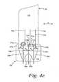
- One non-limiting exampleis shown in FIG. 4e with laser cuts 171a-c including angular portions 173a-c. The angular portions 173a-c extend into and physically connect with the plurality of cuts 114a-c.
- a mechanical punchis used to excise a plurality of test sensors in the sensor-ribbon strip (plurality of test sensors 180 in FIGs. 4a-4d and test sensor 181 in FIG. 4e ).
- the mechanical punchextends through the base-ribbon strip 110 and the lid-ribbon strip 160. It is contemplated that the plurality of test sensors may be excised by other methods.
- the registration apertures 152a,b of FIG. 4aassist in locating the mechanical punch that excises the test sensors from the sensor-ribbon strip 100.
- a sensor-ribbon strip 200includes base-ribbon strip 175 of FIG. 5 and the lid-ribbon strip 160 described above.
- the sensor-ribbon strip 200 of FIG. 6forms a plurality of test sensors 280.
- the sensor-ribbon strip 200 of FIG. 6is the same as the sensor-ribbon strip 100 of FIG. 4a except that the laser cuts 184a-c of FIGs. 5 , 6 have been properly positioned, unlike the laser cuts 114a-c of FIGs. 3 , 4a .
- the laser cuts 170a-c of the sensor-ribbon strip 200 of FIG. 6are formed in the same location as the laser cuts 170a-c of the sensor-ribbon strip 100 of FIG.
- the test sensormay include a spacer.
- the spacer-ribbon strip 305includes a plurality of apertures 307 formed therein to allow access to the conductive areas 120 of the base-ribbon strip 175. It is contemplated that the apertures 307 may be shaped differently as long as the conductive areas 120 of the base-ribbon strip are accessible for later processing.
- the spacer-ribbon strip 305also forms a plurality of apertures 309.
- the apertures 309 of FIG. 7aare generally U-shaped such that the U-shape portion is open to provide a capillary space or fluid chamber between the base and the lid in the test sensor. It is contemplated that the aperture to form a capillary space or fluid chamber may be shaped differently than depicted in FIGs. 7a, 7b and 8 .
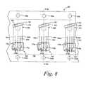
- FIG. 8depicts a sensor-ribbon strip 300 that includes the base-ribbon strip 175 and the spacer-ribbon strip 305 of FIGs. 7a, 7b and the lid-ribbon strip 160.
- the lid-sensor ribbon strip 160is the same as described above in connection of FIG. 6 .
- only a small portion of the spacer-ribbon strip 305is visible through the aperture 155 of the lid-ribbon strip 160.
- the cuts 170a-care formed after the lid-ribbon strip 160, the spacer-ribbon strip 305 and the base-ribbon strip 175 are attached.
- the cuts 170a-care formed in separate acts from the cuts 184a-c. It is contemplated that the spacer-ribbon strip may include the registration apertures instead of the lid-ribbon strip.
- a method of forming an electrochemical multilayer test sensorcomprising the acts of:
- the method of alternative process A wherein the act of partially defining the plurality of electrodesincludes using a laser.
- the method of alternative process Afurther including excising the multi-layer test sensor from the attached base and the second layer.
- a method of forming an electrochemical multilayer test sensorcomprising the acts of:
Landscapes
- Chemical & Material Sciences (AREA)
- Life Sciences & Earth Sciences (AREA)
- Health & Medical Sciences (AREA)
- Engineering & Computer Science (AREA)
- Physics & Mathematics (AREA)
- Organic Chemistry (AREA)
- Biophysics (AREA)
- General Health & Medical Sciences (AREA)
- Wood Science & Technology (AREA)
- Molecular Biology (AREA)
- Zoology (AREA)
- Proteomics, Peptides & Aminoacids (AREA)
- Immunology (AREA)
- Analytical Chemistry (AREA)
- Biochemistry (AREA)
- Hematology (AREA)
- Optics & Photonics (AREA)
- Electrochemistry (AREA)
- Pathology (AREA)
- Chemical Kinetics & Catalysis (AREA)
- Biotechnology (AREA)
- Microbiology (AREA)
- Mechanical Engineering (AREA)
- Plasma & Fusion (AREA)
- General Physics & Mathematics (AREA)
- Bioinformatics & Cheminformatics (AREA)
- General Engineering & Computer Science (AREA)
- Genetics & Genomics (AREA)
- Investigating Or Analysing Biological Materials (AREA)
- Apparatus Associated With Microorganisms And Enzymes (AREA)
- Measurement Of The Respiration, Hearing Ability, Form, And Blood Characteristics Of Living Organisms (AREA)
- Measuring Or Testing Involving Enzymes Or Micro-Organisms (AREA)
Description
- The present invention generally relates to a method of forming a test sensor. More specifically, the present invention generally relates to a method of forming a multilayer test sensor that is adapted to assist in determining a concentration of an analyte.
- The quantitative determination of analytes in body fluids is of great importance in the diagnoses and maintenance of certain physiological abnormalities. For example, lactate, cholesterol and bilirubin should be monitored in certain individuals. In particular, it is important that diabetic individuals frequently check the glucose level in their body fluids to regulate the glucose intake in their diets. The results of such tests can be used to determine what, if any, insulin or other medication needs to be administered. In one type of blood-glucose testing system, test sensors are used to test a sample of blood.
- A test sensor contains biosensing or reagent material that reacts with blood glucose. One type of test sensor is a multilayer test sensor that includes a base and a lid. The base has been attached to the lid in the multi-layer test sensor. One method of attaching the base to the lid is lamination. The act of laminating the base and the lid often has high, less desirable tolerances. In other words, the laminating of the base and the lid tends to have variances that are less than desirable (i.e., +/- 0.015 in.). When the lamination of the base and the lid is not properly aligned, the base and the lid are said to be misregistered.
- An example of a misregistered base and lid is shown in prior art
FIGs. 1a-c. FIG. 1a depicts a sensor-ribbon strip 10 that includes a base-ribbon strip 20 and a lid-ribbon strip 30. The base-ribbon strip 20 includes a plurality oflaser cuts 22a-c that defines a plurality of conductive leads ortraces 26a-d thereon. The conductive leads or traces are the lead portions of the electrodes. To better show thelaser cuts 22a-c formed on the base-ribbon strip 20, thelaser cuts 22a-c have been shown extending upwardly aboverespective apertures 28 formed in the lid-ribbon strip 30 even though they would be partially hidden by the lid-ribbon strip 30. Additionally,FIGs. 1a-c highlight only the areas that will form a portion of the conductive leads or traces, while the actual cuts to form the electrodes or other features of the test sensor are not depicted. - The lid-
ribbon strip 30 ofFIG. 1a forms a plurality ofregistration apertures 32a,b. The lid-ribbon strip 30 is laminated to the base-ribbon strip 20. As shown inFIG. 1a , the lamination of the lid-ribbon strip 30 and the base-ribbon strip 20 is not properly aligned (i.e., misregistered). The misregistration of the lid-ribbon strip 30 and the base-ribbon strip 20 ofFIG. 1a results inconductive leads 26a-d being of unequal widths. Thus, the plurality of test sensors formed from the sensor-ribbon strip 10 would haveconductive leads 26a-d of unequal widths. - When the base and the lid are misregistered, conductive problems between the conductive leads of the test sensor and the meter or instrument may result. For example, misregistration may result in a short between the conductive leads of the test sensors and contacts of the instrument. If a short occurs, the instrument produces an erroneous reading of an analyte concentration or does not produce any reading of the analyte concentration. Misregistration may also result in an erroneous reading of an analyte concentration because the areas of the conductive leads are incorrect.
- Therefore, it would be desirable to use a method that eliminates the lamination tolerances of the base and the lid.
- Subject matter of the present invention is the method of
claim 1 and the claims dependent thereon. FIG. 1a is a top view of a prior art sensor-ribbon strip in which a base-ribbon strip and a lid-ribbon strip have been misregistered.FIG. 1b is a cross-sectional view taken generally alonglines 1b-1b of prior artFIG. 1a .FIG. 1c is a cross-sectional view taken generally alonglines 1c-1c of prior artFIG. 1a .FIG. 2a is a top view of a test sensor including a lid according to one embodiment.FIG. 2b is a top view of the test sensor ofFIG. 2a without the lid.FIG. 3 is a top view of a base-ribbon strip according to one embodiment.FIG. 4a is a top view of the base-ribbon strip ofFIG. 3 laminated to a lid-ribbon strip according to one embodiment in which the base-ribbon strip and lid-ribbon strip are misregistered.FIG. 4b is a cross-sectional view taken generally alonglines 4b-4b ofFIG. 4a .FIG. 4c is a cross-sectional view taken generally alonglines 4c-4c ofFIG. 4a .FIG. 4d is an enlarged top view of a portion of the base-ribbon strip ofFIG. 3 and the lid-ribbon strip ofFIG. 4a with a straight cut according to one embodiment.FIG. 4e is an enlarged top view of a portion of a base ribbon ofFIG. 3 and a lid-ribbon strip ofFIG. 4a with an angled cut according to one embodiment.FIG. 5 is a top view of a base-ribbon strip according to another embodiment.FIG. 6 is a top view of the base-ribbon strip ofFIG. 5 laminated to a lid-ribbon strip in which the base-ribbon strip and the lid-ribbon strip are properly aligned according to another embodiment.FIG. 7a is a top view of a spacer-ribbon strip overlying the base-ribbon strip ofFIG. 5 according to a further embodiment.FIG. 7a is a top view of a spacer-ribbon strip overlying the base-ribbon strip ofFIG. 5 according to a further embodiment.FIG. 7b is a cross-sectional view taken generally alonglines 7b-7b ofFIG. 7a .FIG. 8 is a top view of the base and spacer-ribbon strip ofFIG. 7a laminated to a lid-ribbon strip in which the base-ribbon strip, spacer-ribbon strip and the lid-ribbon strip are properly aligned according to a further embodiment.FIG. 9a is a cross-sectional view taken generally alonglines 9a-9a ofFIG. 8 .FIG. 9b is a cross-sectional view of a test sensor formed from the base/spacer/lid ribbon strip ofFIG. 8 taken generally alonglines 9a-9a ofFIG. 8 .- The present invention is directed to an improved method of forming a multilayer test sensor by eliminating or reducing problems between the conductive leads or traces and the contacts of the instrument caused by misregistering the base and the lid in the attachment (e.g., lamination) act. By eliminating or reducing such problems, erroneous readings of an analyte concentration are reduced, as well as no readings of an analyte concentration are reduced.
- In one embodiment, a test sensor is adapted to receive a fluid sample and is analyzed using an instrument or meter. The test sensor assists in determining the concentrations of analytes. Analytes that may be measured include glucose, lipid profiles (e.g., cholesterol, triglycerides, LDL and HDL), microalbumin, hemoglobin A1C, fructose, lactate, or bilirubin. It is contemplated that other analyte concentrations may be determined. The analytes may be in, for example, a whole blood sample, a blood serum sample, a blood plasma sample, other body fluids like ISF (interstitial fluid) and urine, and non-body fluids.
- The multilayer test sensors to be made using the inventive process include at least a base and a second layer such as a lid. The multilayer test sensors are electrochemical test sensors. The base and lid may be made from a variety of materials such as polymeric materials. Non-limiting examples of polymeric materials that may be used to form the base and lid include polycarbonate, polyethylene terephthalate (PET), polystyrene, polyimide, and combinations thereof. As will be discussed below, the multilayer test sensors may include additional layers such as a spacer. For example, a base, spacer and lid may form the multilayer test sensor in another embodiment.
- One non-limiting example of a test sensor is shown in
FIGs. 2a, 2b . The test sensor may be formed from a sensor-ribbon strip that includes a base-ribbon strip and a lid-ribbon strip.FIGs. 2a, 2b depict atest sensor 70 that includes a base 72,capillary channel 74, a lid 76, a plurality ofelectrodes respective electrodes capillary channel 74 is formed when the base and the lid are attached to each other. Thecapillary channel 74 provides an enclosed flow path for introducing the sample into thetest sensor 70 and eventually contacting theelectrodes - As shown in
FIG. 2b , the test sensor 70 (without the lid 76) includes a reactive or fluid-receivingarea 86 that contains an enzyme. The enzyme is selected to react with the desired analyte or analytes to be tested so as to assist in determining an analyte concentration of a fluid sample. Thereactive area 86 includes a reagent for converting an analyte of interest (e.g., glucose) in a fluid test sample (e.g., blood) into a chemical species that is electrochemically measurable, in terms of the electrical current it produces, by the components of the electrode pattern. The reagent typically contains an enzyme (e.g., glucose oxidase), which reacts with the analyte (e.g., glucose) and with an electron acceptor (e.g., a ferricyanide salt) to produce an electrochemically measurable species that can be detected by the electrodes. Thereactive area 86 may comprise a polymer, an enzyme, and an electron acceptor. Thereactive area 86 also may include additional ingredients such as a buffer and a surfactant in some embodiments of the present invention. It is contemplated that other enzymes may be used to react with glucose such as glucose dehydrogenase. If the concentration of another analyte is to be determined, an appropriate enzyme is selected to react with the analytes. - The plurality of electrodes of
FIG. 2b includes at least a counter electrode 78 and a working electrode 80 according to this embodiment. Other electrodes such as adetection electrode 82 and ahematocrit electrode 84 are shown inFIG. 2b . It is contemplated that more or less electrodes can be formed in the method of the present invention. For example, the test sensor may include exactly two electrodes or at least three electrodes. The exactly two electrodes may be a working electrode and a counter electrode in which an electrochemically created current flow when these electrodes are electrically connected and a potential is created between them. - The detection electrode may be an electrode that detects an underfill condition. It is contemplated that other electrodes may be used such as a hematocrit electrode that assists in correcting for the bias that occurs with selected hematocrit concentrations. Additional electrodes include, but are not limited to, electrodes that detect other analytes or species that may potentially interfere with the measurement of the desired analyte. Also, a second working electrode that assists in determining the concentration of another analyte may be used.
- The electrodes are formed of conductive materials such as, for example, metallic materials (e.g., gold, platinum, palladium, rhodium, ruthenium, or combinations thereof) or carbon. Examples of components of electrochemical test sensors, including their operation, may be found at, for example,
U.S. Patent No. 6,531,040 . It is contemplated that other components of electrochemical test sensors may be used other than that disclosed in, for example,U.S. Patent No. 6,531,040 . - The present invention is directed to an inventive process for forming a test sensor and, more specifically, an electrochemical test sensor. In one method, the electrochemical multilayer test sensors may be formed from a test-sensor ribbon. The ribbon is made from processes such as a multiple sheet process or a web process.
- Referring to
FIG. 3 , a base-ribbon strip 110 is adapted to form a plurality of bases to be used in forming an electrochemical test sensor. Thetest sensors 180 to be formed from the base-ribbon strip 110 are depicted inFIG. 3 as dashed lines since they are not generally formed in the base-ribbon strip at this stage of processing. For improved efficiency, the test sensors are generally formed after the base-ribbon strip and the lid-ribbon strip have been attached. - The base-
ribbon strip 110 ofFIG. 3 is adapted to be attached (e.g., laminated) with a second layer such as, for example, a lid-ribbon strip. The base-ribbon strip 110 includes a conductive/reactive area 120, which will eventually form a plurality of conductive leads that is adapted to contact a meter or instrument. These conductive leads electrically connect the plurality of electrodes with the meter. The base-ribbon strip 110 also forms a plurality ofapertures 153 that will assist in defining the test sensors.FIG. 3 depicts the areas that will form a portion of the conductive leads or traces in later processing, while the actual cuts to form the electrodes or other features of the test sensor are not depicted. Some of these features are depicted above inFIGs. 2a, 2b . It is contemplated that other patterns of electrodes may be used other than the pattern depicted inFIG. 2b . The electrodes, as well as other features, are typically formed on the base-ribbon strip at this stage of the processing. - Before attachment to the lid-ribbon strip, the base-
ribbon strip 110 ofFIG. 3 , however, has not fully defined the plurality of conductive leads in theconductive area 120. In other words, the conductive leads of the plurality of electrodes are partially defined. In one process, a plurality oflaser cuts 114a-c begins the process of defining the plurality of conductive leads in theconductive area 120. In this process, the plurality of electrodes has been partially defined but, as discussed above, are not shown inFIG. 3 . The plurality of electrodes is not fully defined until the base-ribbon strip is attached to a second layer, which defines a reaction zone. - One process of defining the electrodes is by cutting the base-ribbon strip. For example, the plurality of electrodes may be defined by using a mask and a laser such as, for example, an Excimer laser or a carbon dioxide-based laser. One example of a mask is a chrome-on-glass mask in which the beam of light is only allowed to pass through selected areas.
- According to another method, the plurality of electrodes on the base-
ribbon strip 110 is partially formed with a laser using direct writing of the lines. As discussed above, the plurality of electrodes is not fully defined until the base-ribbon strip is attached to a second layer so as to define a reaction zone. In a method using a laser with direct writing of the lines, a laser beam of light is moved so as to partially define the plurality of electrodes. Lasers that produce a beam of energy capable of removing a layer and that can be moved to form a pattern may be used in this method. Non-limiting examples of such lasers are carbon dioxide-based lasers and yttrium-based lasers such as yttrium aluminum garnet (YAG) lasers. - It is contemplated that the plurality of electrodes may be defined on the base-ribbon strip by other methods such as, for example, printing (e.g., screen-printing), coating (e.g., reverse roll), vapor deposition, sputtering and electrochemical deposition.
- After partially defining the plurality of electrodes, the base-
ribbon strip 110 is attached to a second layer. In one embodiment, the base-ribbon strip 110 is attached to a lid-ribbon strip 160 to form a sensor-ribbon strip 100 such as shown inFIG. 4a . After attachment of the base-ribbon strip 110 and the lid-ribbon strip 160 so as to define a reaction zone, the plurality of electrodes is fully defined. It is contemplated that the second layer may be a spacer-ribbon strip such as shown inFIGs. 7-9 . According to another embodiment, the second layer may be a spacer-lid ribbon strip combination in which the spacer-ribbon strip and lid-ribbon strip have been previously attached before the spacer-lid ribbon strip combination is later attached to the base-ribbon strip. - The base-ribbon strip (e.g., base-ribbon strip 110) may be attached to the second layer (e.g., lid-ribbon strip 160) using, for example, a pressure-sensitive adhesive and/or a hot melt adhesive. Thus, the attachment between the base-ribbon strip and the second surface uses pressure, heat or a combination thereof. It is contemplated that other materials may be used to attach the base-ribbon strip to the second surface. It is also contemplated that the base-ribbon strip and the lid-ribbon strip may be attached using ultrasonic energy or solvent welding.
- As shown in
FIG. 4a , the sensor-ribbon strip 100 includes the base-ribbon strip 110 and a lid-ribbon strip 160. The lid ribbon-strip 160 is adapted to form a plurality of lids. The lid ribbon-strip 160 forms a plurality ofregistration apertures 152a,b therein and also forms a plurality ofapertures 154 adapted to allow access to respectiveconductive areas 120 of the base-ribbon strip 110. Theconductive areas 120 are the areas in which the meter is adapted to contact the test sensors. The lid-ribbon strip 160 also forms a plurality ofapertures 155 that assists in defining the periphery of the lid of the test sensor. In one embodiment, the plurality ofapertures 155 and the plurality ofapertures 153 are slightly offset, which allows for a slight overhang of the lid relative to the base in the test sensor. This is shown inFIG. 4a as offsetarea 157. The slight overhang assists in receiving and guiding the sample to the reactive or fluid-receiving area (not shown inFIG. 4a ). It is contemplated that the test sensor may not include an overhang at the fluid-receiving area (i.e., neither the base nor the lid extends outwardly from the other at the fluid-receiving area). - As shown in
FIGs. 4a ,4d , a plurality oflaser cuts 170a-c fully defines the plurality ofconductive leads 120a-d after the base-ribbon strip 110 and the lid-ribbon strip 160 have been laminated. The conductive leads 120a-d may be formed by the processes discussed above in connection with the plurality of electrodes, including laser processes. The laser cuts 170a-c and thelaser cuts 114a-c are performed at distinct times and are considered to be separate acts. The laser used in forming thelaser cuts 170a-c, however, may be the same laser used in the separate act of forming thelaser cuts 114a-c. It is contemplated that the laser used in forming thelaser cuts 170a-c and 114a-c may be different. - The plurality of
laser cuts 170a-c gains assess to theconductive area 120 of the base-ribbon strip 110 throughrespective apertures 154 formed in the lid-ribbon strip 160. As shown inFIG. 4d , the plurality oflaser cuts 170a-c is aligned such that the plurality ofconductive leads 120a-d have generally the same widths W1-W4. Additionally, as best shown inFIG. 4d , a portion of thelaser cuts 114a-c is exposed through theaperture 154. - To prevent or inhibit the plurality of
conductive leads 120a-d from being misregistered, the laser uses a guide or mark (registration apertures 152a,b inFIG. 4a ). It is contemplated that other guides may be used to register the laser such as a plurality of marks formed from a laser-cutting operation on the base-ribbon strip. Laser-cutting is desirable because of the ability to maintain low manufacturing tolerances (typically less than 0.005 in.) when using mechanical or optical guides. By defining the conductive leads 120a-d using a laser and the same registration apertures used for excising the test sensors allows for tighter tolerances as compared to the prior art process discussed above in connection with prior artFIGs. 1a-1c . - As shown in
FIGs. 4a ,4d , each of the plurality oflaser cuts 170a-c is formed in a shape of a general "T". It is contemplated that the laser cuts may be of different shapes than depicted inFIGs. 4a ,4d . The laser cuts 170a-c ofFIG. 4a have respective generally.horizontal portions 172a-c and respective generallyvertical portions 174a-c. The laser cuts 170a-c are formed so as to assist in physically connecting with respective plurality ofcuts 114a-c. - The length (L1) of the generally
horizontal portions 172a-c (shown inFIG. 4d ) is selected to take into account the manufacturing variances of therespective cuts 114a-c. In other words, the greater the potential variance of therespective cuts 114a-c in the horizontal direction (directions of arrow A), the longer the length L1 of the generallyhorizontal portions 172a-c. Thus,respective laser cuts 114a-c desirably should not be misregistered to the left or the right of the respective generallyhorizontal portions 172a-c as viewed inFIGs. 4a ,4d . Additionally, to reduce the effect of manufacturing tolerances of thelaser cuts 114a-c in the vertical direction (as viewed inFIGs. 4a ,4d ), it is desirable for thelaser cuts 114a-c to partially extend into the area accessible throughapertures 154. - It is contemplated that the generally
horizontal portions 172a-c ofFIGs. 4a ,4d may be replaced by angled portions that physical connect with the plurality ofcuts 114a-c. One non-limiting example is shown inFIG. 4e withlaser cuts 171a-c includingangular portions 173a-c. Theangular portions 173a-c extend into and physically connect with the plurality ofcuts 114a-c. - In one method, a mechanical punch is used to excise a plurality of test sensors in the sensor-ribbon strip (plurality of
test sensors 180 inFIGs. 4a-4d and test sensor 181 inFIG. 4e ). The mechanical punch extends through the base-ribbon strip 110 and the lid-ribbon strip 160. It is contemplated that the plurality of test sensors may be excised by other methods. In a desired embodiment, theregistration apertures 152a,b ofFIG. 4a assist in locating the mechanical punch that excises the test sensors from the sensor-ribbon strip 100. - Referring to
FIG. 6 , a sensor-ribbon strip 200 includes base-ribbon strip 175 ofFIG. 5 and the lid-ribbon strip 160 described above. The sensor-ribbon strip 200 ofFIG. 6 forms a plurality oftest sensors 280. The sensor-ribbon strip 200 ofFIG. 6 is the same as the sensor-ribbon strip 100 ofFIG. 4a except that thelaser cuts 184a-c ofFIGs. 5 ,6 have been properly positioned, unlike thelaser cuts 114a-c ofFIGs. 3 ,4a . The laser cuts 170a-c of the sensor-ribbon strip 200 ofFIG. 6 are formed in the same location as thelaser cuts 170a-c of the sensor-ribbon strip 100 ofFIG. 4a even though thelaser cuts 114a-c ofFIGs. 4a ,4d were misregistered and thelaser cuts 184a-c ofFIGs. 5 ,6 were properly registered. This is because thelaser cuts 170a-c were formed usingrespective registration apertures 152a,b. - . As discussed above, it is contemplated that the test sensor may include a spacer. In one embodiment depicted in
FIGs. 7a, 7b , a base-ribbon strip 175 ofFIG. 5 with a spacer-ribbon strip 305 attached thereto. The spacer-ribbon strip 305 includes a plurality ofapertures 307 formed therein to allow access to theconductive areas 120 of the base-ribbon strip 175. It is contemplated that theapertures 307 may be shaped differently as long as theconductive areas 120 of the base-ribbon strip are accessible for later processing. - The spacer-
ribbon strip 305 also forms a plurality ofapertures 309. Theapertures 309 ofFIG. 7a are generally U-shaped such that the U-shape portion is open to provide a capillary space or fluid chamber between the base and the lid in the test sensor. It is contemplated that the aperture to form a capillary space or fluid chamber may be shaped differently than depicted inFIGs. 7a, 7b and8 . FIG. 8 depicts a sensor-ribbon strip 300 that includes the base-ribbon strip 175 and the spacer-ribbon strip 305 ofFIGs. 7a, 7b and the lid-ribbon strip 160. The lid-sensor ribbon strip 160 is the same as described above in connection ofFIG. 6 . As shown inFIG. 8 , only a small portion of the spacer-ribbon strip 305 is visible through theaperture 155 of the lid-ribbon strip 160. Thecuts 170a-c are formed after the lid-ribbon strip 160, the spacer-ribbon strip 305 and the base-ribbon strip 175 are attached. As discussed above, thecuts 170a-c are formed in separate acts from thecuts 184a-c. It is contemplated that the spacer-ribbon strip may include the registration apertures instead of the lid-ribbon strip.- A method of forming an electrochemical multilayer test sensor, the multilayer test sensor including a base, a second layer and a reactive layer, the reactive area including an enzyme, the test sensor being adapted to be used in a meter and assist in determining the concentration of an analyte, the method comprising the acts of:
- partially defining a plurality of electrodes and their respective conductive leads on the base;
- after partially defining the plurality of electrodes and their respective conductive leads on the base, attaching the base to a second layer to define a reaction zone in which the plurality of electrodes are fully defined; and
- after attaching the base to the second layer, fully defining the plurality of conductive leads on the base of the test sensor.
- The method of alternative process A wherein the plurality of conductive leads and plurality of electrodes are defined by a laser.
- The method of alternative process A wherein the plurality of conductive leads and plurality of electrodes are defined by printing, coating, vapor deposition, sputtering or electrochemical deposition.
- The method of alternative process A wherein the act of partially defining the plurality of electrodes includes using a laser.
- The method of alternative process A wherein the second layer is a lid.
- The method of alternative process A wherein the second layer is a spacer.
- The method of alternative process A wherein the second layer is a spacer-lid combination.
- The method of alternative process A wherein the second layer forms a plurality of guides.
- The method of alternative process H wherein the plurality of guides is a plurality of registration apertures.
- The method of alternative process A further including excising the multi-layer test sensor from the attached base and the second layer.
- The method of alternative process J wherein the act of excising the multi-layer test sensor from the attached base and the second layer includes using a mechanical punch.
- The method of alternative process J wherein the act of excising the multiple-test sensor and the act of defining the plurality of conductive traces are registered with each other.
- The method of alternative process A wherein the base and the second layer are attached using an adhesive.
- The method of alternative process A wherein the plurality of electrodes comprises a metallic conductive material.
- The method of alternative process A wherein the enzyme is glucose oxidase or glucose dehydrogenase.
- A method of forming an electrochemical multilayer test sensor, the multilayer test sensor including a base, a second layer and a reactive layer, the reactive area including an enzyme, the test sensor being adapted to be used in a meter and assist in determining the concentration of an analyte, the method comprising the acts of:
- partially defining a plurality of electrodes and their respective conductive leads on the base via a laser;
- after partially defining the plurality of electrodes and their respective conductive leads on the base, attaching the base to a second layer to define a reaction zone in which the plurality of electrodes are fully defined;
- after attaching the base to the second layer, fully defining the plurality of conductive leads on the base of the test sensor; and
- excising the test sensor from the attached base and the second layer.
- The method of alternative process P wherein the second layer is a lid.
- The method of alternative process P wherein the second layer is a spacer.
- The method of alternative process P wherein the second layer is a spacer-lid combination.
- The method of alternative process P wherein the act of excising the multi-layer test sensor from the attached base and the second layer includes using a mechanical punch.
- The method of alternative process P wherein the act of excising the multiple-test sensor and the act of defining the plurality of conductive traces are registered with each other.
- The method of alternative process P wherein the base and the second layer are attached using an adhesive.
- The method of alternative process P wherein the plurality of electrodes comprises a metallic conductive material.
- The method of alternative process P wherein the enzyme is glucose oxidase or glucose dehydrogenase.
Claims (13)
- A method of forming an electrochemical multilayer test sensor (180, 181, 280, 380), the multilayer test sensor (180, 181, 280, 380) including a base (110, 175, 210), a second layer (160, 305) and a reactive area, the reactive area including an enzyme, the test sensor (180, 181, 280, 380) being adapted to be used in a meter and assist in determining the concentration of an analyte, the base (110, 175, 210) including a conductive area (120) adapted to contact the meter, the method comprising the acts of:partially defining a plurality of electrodes on the base (110, 175, 210) outside the conductive area (120) and defining a plurality of respective first conductive leads that extend from outside the conductive area (120) only partially into the conductive area (120);after partially defining the plurality of electrodes and the plurality of respective first conductive leads on the base (110, 175, 210), attaching the base (110, 175, 210) to the second layer (160, 305) thereby(i) forming a capillary space which forms a reaction zone in which the plurality of electrodes are fully defined; and(ii) leaving the conductive area (120) uncovered by the second layer (160, 305) and exposing only the portions of the first conductive leads that extend partially into the conductive area (120); andafter attaching the base (110, 175, 210) to the second layer (160, 205), further processing to define a plurality of second conductive leads (120a-d) in the conductive area (120) whereby the plurality of first conductive leads together with the plurality of second conductive leads (120a-d) form a plurality of fully defined conductive leads on the base of the test sensor adapted to connect the plurality of electrodes with the meter.
- The method of claim 1, wherein the acts of defining the plurality of first conductive leads, defining the plurality of second conductive leads (120a-d) and partially defining the plurality of electrodes include using a laser.
- The method of claim 1, wherein the acts of defining the plurality of first conductive leads, defining the plurality of second conductive leads and partially defining the plurality of electrodes are carried out by printing, coating, vapor deposition, sputtering or electrochemical deposition.
- The method of one of the claims 1 to 3, wherein the second layer (160) is a lid.
- The method of one of the claims 1 to 3, wherein the second layer (305) is a spacer.
- The method of one of the claims 1 to 5, wherein the base (110, 175, 210) and the second layer (160, 305) are in the form of respective base and second layer-ribbon strips.
- The method of claim 6, further including excising the multi-layer test sensor (180, 181, 280, 380) from the respective attached base-ribbon strip and the second layer-ribbon strip.
- The method of claim 7, wherein the act of excising the multi-layer test sensor (180, 181, 280, 380) from the attached base-ribbon strip and the second layer-ribbon strip includes using a mechanical punch.
- The method of claim 7, wherein the act of excising the multiple-test sensor (180, 181, 280, 380) and the act of defining the plurality of second conductive leads (120a-d) are registered with each other.
- The method of one of the claims 1 to 9, wherein the base (110, 175, 210) and the second layer (160, 305) are attached using an adhesive.
- The method of one of the claims 1 to 10, wherein the plurality of electrodes comprises a metallic conductive material.
- The method of one of the claims 1 to 11, wherein the enzyme is glucose oxidase or glucose dehydrogenase.
- The method of claim 1, wherein the act of partially defining a plurality of electrodes and defining a plurality of respective first conductive leads includes forming a plurality of first laser cuts (114a-c, 184a-c) in the base (110, 175, 210) outside the conductive area (120) and extending only partially into the conductive area (120); and
wherein the act of further processing to define a plurality of second conductive leads (120a-d) includes forming a plurality of second laser cuts (170a-c) in the base in the conductive area (120).
Priority Applications (1)
| Application Number | Priority Date | Filing Date | Title |
|---|---|---|---|
| PL06848776TPL1971460T3 (en) | 2005-12-27 | 2006-12-21 | A method of forming a multilayer test sensor |
Applications Claiming Priority (2)
| Application Number | Priority Date | Filing Date | Title |
|---|---|---|---|
| US75414105P | 2005-12-27 | 2005-12-27 | |
| PCT/US2006/048872WO2007075935A2 (en) | 2005-12-27 | 2006-12-21 | A method of forming a multilayer test sensor |
Publications (2)
| Publication Number | Publication Date |
|---|---|
| EP1971460A2 EP1971460A2 (en) | 2008-09-24 |
| EP1971460B1true EP1971460B1 (en) | 2015-09-09 |
Family
ID=38110270
Family Applications (1)
| Application Number | Title | Priority Date | Filing Date |
|---|---|---|---|
| EP06848776.8AActiveEP1971460B1 (en) | 2005-12-27 | 2006-12-21 | A method of forming a multilayer test sensor |
Country Status (8)
| Country | Link |
|---|---|
| US (1) | US8083884B2 (en) |
| EP (1) | EP1971460B1 (en) |
| JP (1) | JP4942763B2 (en) |
| CN (1) | CN101410218B (en) |
| BR (1) | BRPI0620731A2 (en) |
| ES (1) | ES2550583T3 (en) |
| PL (1) | PL1971460T3 (en) |
| WO (1) | WO2007075935A2 (en) |
Families Citing this family (7)
| Publication number | Priority date | Publication date | Assignee | Title |
|---|---|---|---|---|
| WO2009046161A1 (en) | 2007-10-05 | 2009-04-09 | Bayer Healthcare Llc | Method of defining electrodes using laser-ablation and dielectric material |
| WO2009054291A1 (en)* | 2007-10-26 | 2009-04-30 | Mitsubishi Pencil Co., Ltd. | Mechanical pencil |
| US8888973B2 (en) | 2011-07-29 | 2014-11-18 | Roche Diagnostics Operations, Inc. | Encoded biosensors and methods of manufacture and use thereof |
| US9754708B2 (en) | 2011-07-29 | 2017-09-05 | Roche Diabetes Care, Inc. | Encoded biosensors and methods of manufacture and use thereof |
| US9097659B2 (en)* | 2013-03-14 | 2015-08-04 | Bayer Healthcare Llc | Maintaining electrode function during manufacture with a protective layer |
| US10197522B2 (en) | 2015-03-18 | 2019-02-05 | Materion Corporation | Multilayer constructs for metabolite strips providing inert surface and mechanical advantage |
| US10378098B2 (en) | 2015-03-18 | 2019-08-13 | Materion Corporation | Methods for optimized production of multilayer metal/transparent conducting oxide (TCO) constructs |
Family Cites Families (9)
| Publication number | Priority date | Publication date | Assignee | Title |
|---|---|---|---|---|
| JPS6044298A (en)* | 1983-08-22 | 1985-03-09 | 光洋自動機株式会社 | Manufacture of punching label, etc. |
| CA2305922C (en)* | 1999-08-02 | 2005-09-20 | Bayer Corporation | Improved electrochemical sensor design |
| US6662439B1 (en)* | 1999-10-04 | 2003-12-16 | Roche Diagnostics Corporation | Laser defined features for patterned laminates and electrodes |
| US6767441B1 (en)* | 2001-07-31 | 2004-07-27 | Nova Biomedical Corporation | Biosensor with peroxidase enzyme |
| KR100969452B1 (en)* | 2001-08-09 | 2010-07-14 | 오르보테크 엘티디. | Target exposure system and method of multilayered electrical circuits |
| US7645373B2 (en)* | 2003-06-20 | 2010-01-12 | Roche Diagnostic Operations, Inc. | System and method for coding information on a biosensor test strip |
| CN1579697A (en)* | 2003-08-07 | 2005-02-16 | 鸿富锦精密工业(深圳)有限公司 | Laser working method |
| JP4334969B2 (en)* | 2003-10-02 | 2009-09-30 | パナソニック株式会社 | Blood component analysis sensor |
| JP4458802B2 (en)* | 2003-10-02 | 2010-04-28 | パナソニック株式会社 | Method for measuring glucose in blood and sensor used therefor |
- 2006
- 2006-12-21EPEP06848776.8Apatent/EP1971460B1/enactiveActive
- 2006-12-21PLPL06848776Tpatent/PL1971460T3/enunknown
- 2006-12-21CNCN2006800495173Apatent/CN101410218B/enactiveActive
- 2006-12-21ESES06848776.8Tpatent/ES2550583T3/enactiveActive
- 2006-12-21WOPCT/US2006/048872patent/WO2007075935A2/enactiveApplication Filing
- 2006-12-21BRBRPI0620731-6Apatent/BRPI0620731A2/ennot_activeApplication Discontinuation
- 2006-12-21USUS12/086,240patent/US8083884B2/enactiveActive
- 2006-12-21JPJP2008548637Apatent/JP4942763B2/enactiveActive
Also Published As
| Publication number | Publication date |
|---|---|
| EP1971460A2 (en) | 2008-09-24 |
| ES2550583T3 (en) | 2015-11-10 |
| CN101410218A (en) | 2009-04-15 |
| JP2009521702A (en) | 2009-06-04 |
| BRPI0620731A2 (en) | 2011-11-22 |
| US20090159197A1 (en) | 2009-06-25 |
| JP4942763B2 (en) | 2012-05-30 |
| WO2007075935A2 (en) | 2007-07-05 |
| US8083884B2 (en) | 2011-12-27 |
| WO2007075935A3 (en) | 2008-10-23 |
| PL1971460T3 (en) | 2016-01-29 |
| CN101410218B (en) | 2012-11-21 |
Similar Documents
| Publication | Publication Date | Title |
|---|---|---|
| AU2010212483B2 (en) | Electrochemical cell and method of making an electrochemical cell | |
| US8529741B2 (en) | System and methods for determining an analyte concentration incorporating a hematocrit correction | |
| EP1971460B1 (en) | A method of forming a multilayer test sensor | |
| US8124014B2 (en) | Auto-calibration circuit or label and method of forming the same | |
| US9261479B2 (en) | Electrochemical test sensor and method of making the same | |
| US9658188B2 (en) | Electrochemical test sensor | |
| US20090078030A1 (en) | Test Sensor With a Fluid Chamber Opening | |
| US8273226B2 (en) | Wear-resistant electrochemical test sensor and method of forming the same | |
| US7797987B2 (en) | Test sensor with a side vent and method of making the same | |
| US8399070B2 (en) | Method of defining electrodes using laser-ablation and dielectric material | |
| EP2098161A1 (en) | Test sensor with a side vent and method of making the same |
Legal Events
| Date | Code | Title | Description |
|---|---|---|---|
| PUAI | Public reference made under article 153(3) epc to a published international application that has entered the european phase | Free format text:ORIGINAL CODE: 0009012 | |
| AK | Designated contracting states | Kind code of ref document:A2 Designated state(s):AT BE BG CH CY CZ DE DK EE ES FI FR GB GR HU IE IS IT LI LT LU LV MC NL PL PT RO SE SI SK TR | |
| AX | Request for extension of the european patent | Extension state:AL BA HR MK RS | |
| R17D | Deferred search report published (corrected) | Effective date:20081023 | |
| 17P | Request for examination filed | Effective date:20090423 | |
| RBV | Designated contracting states (corrected) | Designated state(s):AT BE BG CH CY CZ DE DK EE ES FI FR GB GR HU IE IS IT LI LT LU LV MC NL PL PT RO SE SI SK TR | |
| 17Q | First examination report despatched | Effective date:20091012 | |
| DAX | Request for extension of the european patent (deleted) | ||
| RAP1 | Party data changed (applicant data changed or rights of an application transferred) | Owner name:BAYER HEALTHCARE LLC | |
| GRAP | Despatch of communication of intention to grant a patent | Free format text:ORIGINAL CODE: EPIDOSNIGR1 | |
| INTG | Intention to grant announced | Effective date:20150430 | |
| GRAS | Grant fee paid | Free format text:ORIGINAL CODE: EPIDOSNIGR3 | |
| GRAA | (expected) grant | Free format text:ORIGINAL CODE: 0009210 | |
| AK | Designated contracting states | Kind code of ref document:B1 Designated state(s):AT BE BG CH CY CZ DE DK EE ES FI FR GB GR HU IE IS IT LI LT LU LV MC NL PL PT RO SE SI SK TR | |
| REG | Reference to a national code | Ref country code:GB Ref legal event code:FG4D | |
| REG | Reference to a national code | Ref country code:AT Ref legal event code:REF Ref document number:747721 Country of ref document:AT Kind code of ref document:T Effective date:20150915 Ref country code:CH Ref legal event code:EP | |
| REG | Reference to a national code | Ref country code:IE Ref legal event code:FG4D | |
| REG | Reference to a national code | Ref country code:DE Ref legal event code:R096 Ref document number:602006046627 Country of ref document:DE | |
| REG | Reference to a national code | Ref country code:ES Ref legal event code:FG2A Ref document number:2550583 Country of ref document:ES Kind code of ref document:T3 Effective date:20151110 | |
| REG | Reference to a national code | Ref country code:FR Ref legal event code:PLFP Year of fee payment:10 | |
| REG | Reference to a national code | Ref country code:NL Ref legal event code:MP Effective date:20150909 | |
| PG25 | Lapsed in a contracting state [announced via postgrant information from national office to epo] | Ref country code:GR Free format text:LAPSE BECAUSE OF FAILURE TO SUBMIT A TRANSLATION OF THE DESCRIPTION OR TO PAY THE FEE WITHIN THE PRESCRIBED TIME-LIMIT Effective date:20151210 Ref country code:LT Free format text:LAPSE BECAUSE OF FAILURE TO SUBMIT A TRANSLATION OF THE DESCRIPTION OR TO PAY THE FEE WITHIN THE PRESCRIBED TIME-LIMIT Effective date:20150909 Ref country code:LV Free format text:LAPSE BECAUSE OF FAILURE TO SUBMIT A TRANSLATION OF THE DESCRIPTION OR TO PAY THE FEE WITHIN THE PRESCRIBED TIME-LIMIT Effective date:20150909 Ref country code:FI Free format text:LAPSE BECAUSE OF FAILURE TO SUBMIT A TRANSLATION OF THE DESCRIPTION OR TO PAY THE FEE WITHIN THE PRESCRIBED TIME-LIMIT Effective date:20150909 | |
| REG | Reference to a national code | Ref country code:LT Ref legal event code:MG4D | |
| REG | Reference to a national code | Ref country code:AT Ref legal event code:MK05 Ref document number:747721 Country of ref document:AT Kind code of ref document:T Effective date:20150909 | |
| PG25 | Lapsed in a contracting state [announced via postgrant information from national office to epo] | Ref country code:SE Free format text:LAPSE BECAUSE OF FAILURE TO SUBMIT A TRANSLATION OF THE DESCRIPTION OR TO PAY THE FEE WITHIN THE PRESCRIBED TIME-LIMIT Effective date:20150909 | |
| PGFP | Annual fee paid to national office [announced via postgrant information from national office to epo] | Ref country code:PL Payment date:20151216 Year of fee payment:10 Ref country code:ES Payment date:20151228 Year of fee payment:10 | |
| PG25 | Lapsed in a contracting state [announced via postgrant information from national office to epo] | Ref country code:NL Free format text:LAPSE BECAUSE OF FAILURE TO SUBMIT A TRANSLATION OF THE DESCRIPTION OR TO PAY THE FEE WITHIN THE PRESCRIBED TIME-LIMIT Effective date:20150909 | |
| PG25 | Lapsed in a contracting state [announced via postgrant information from national office to epo] | Ref country code:CZ Free format text:LAPSE BECAUSE OF FAILURE TO SUBMIT A TRANSLATION OF THE DESCRIPTION OR TO PAY THE FEE WITHIN THE PRESCRIBED TIME-LIMIT Effective date:20150909 Ref country code:EE Free format text:LAPSE BECAUSE OF FAILURE TO SUBMIT A TRANSLATION OF THE DESCRIPTION OR TO PAY THE FEE WITHIN THE PRESCRIBED TIME-LIMIT Effective date:20150909 Ref country code:IS Free format text:LAPSE BECAUSE OF FAILURE TO SUBMIT A TRANSLATION OF THE DESCRIPTION OR TO PAY THE FEE WITHIN THE PRESCRIBED TIME-LIMIT Effective date:20160109 Ref country code:SK Free format text:LAPSE BECAUSE OF FAILURE TO SUBMIT A TRANSLATION OF THE DESCRIPTION OR TO PAY THE FEE WITHIN THE PRESCRIBED TIME-LIMIT Effective date:20150909 | |
| PG25 | Lapsed in a contracting state [announced via postgrant information from national office to epo] | Ref country code:RO Free format text:LAPSE BECAUSE OF FAILURE TO SUBMIT A TRANSLATION OF THE DESCRIPTION OR TO PAY THE FEE WITHIN THE PRESCRIBED TIME-LIMIT Effective date:20150909 Ref country code:BE Free format text:LAPSE BECAUSE OF NON-PAYMENT OF DUE FEES Effective date:20151231 Ref country code:PT Free format text:LAPSE BECAUSE OF FAILURE TO SUBMIT A TRANSLATION OF THE DESCRIPTION OR TO PAY THE FEE WITHIN THE PRESCRIBED TIME-LIMIT Effective date:20160111 Ref country code:AT Free format text:LAPSE BECAUSE OF FAILURE TO SUBMIT A TRANSLATION OF THE DESCRIPTION OR TO PAY THE FEE WITHIN THE PRESCRIBED TIME-LIMIT Effective date:20150909 | |
| REG | Reference to a national code | Ref country code:DE Ref legal event code:R097 Ref document number:602006046627 Country of ref document:DE | |
| PLBE | No opposition filed within time limit | Free format text:ORIGINAL CODE: 0009261 | |
| STAA | Information on the status of an ep patent application or granted ep patent | Free format text:STATUS: NO OPPOSITION FILED WITHIN TIME LIMIT | |
| PG25 | Lapsed in a contracting state [announced via postgrant information from national office to epo] | Ref country code:MC Free format text:LAPSE BECAUSE OF FAILURE TO SUBMIT A TRANSLATION OF THE DESCRIPTION OR TO PAY THE FEE WITHIN THE PRESCRIBED TIME-LIMIT Effective date:20150909 Ref country code:LU Free format text:LAPSE BECAUSE OF FAILURE TO SUBMIT A TRANSLATION OF THE DESCRIPTION OR TO PAY THE FEE WITHIN THE PRESCRIBED TIME-LIMIT Effective date:20151221 | |
| 26N | No opposition filed | Effective date:20160610 | |
| PG25 | Lapsed in a contracting state [announced via postgrant information from national office to epo] | Ref country code:SI Free format text:LAPSE BECAUSE OF FAILURE TO SUBMIT A TRANSLATION OF THE DESCRIPTION OR TO PAY THE FEE WITHIN THE PRESCRIBED TIME-LIMIT Effective date:20150909 Ref country code:DK Free format text:LAPSE BECAUSE OF FAILURE TO SUBMIT A TRANSLATION OF THE DESCRIPTION OR TO PAY THE FEE WITHIN THE PRESCRIBED TIME-LIMIT Effective date:20150909 | |
| REG | Reference to a national code | Ref country code:IE Ref legal event code:MM4A | |
| PG25 | Lapsed in a contracting state [announced via postgrant information from national office to epo] | Ref country code:IE Free format text:LAPSE BECAUSE OF NON-PAYMENT OF DUE FEES Effective date:20151221 | |
| REG | Reference to a national code | Ref country code:FR Ref legal event code:PLFP Year of fee payment:11 | |
| PG25 | Lapsed in a contracting state [announced via postgrant information from national office to epo] | Ref country code:BE Free format text:LAPSE BECAUSE OF FAILURE TO SUBMIT A TRANSLATION OF THE DESCRIPTION OR TO PAY THE FEE WITHIN THE PRESCRIBED TIME-LIMIT Effective date:20150909 | |
| PG25 | Lapsed in a contracting state [announced via postgrant information from national office to epo] | Ref country code:IT Free format text:LAPSE BECAUSE OF NON-PAYMENT OF DUE FEES Effective date:20151221 | |
| PG25 | Lapsed in a contracting state [announced via postgrant information from national office to epo] | Ref country code:BG Free format text:LAPSE BECAUSE OF FAILURE TO SUBMIT A TRANSLATION OF THE DESCRIPTION OR TO PAY THE FEE WITHIN THE PRESCRIBED TIME-LIMIT Effective date:20150909 Ref country code:HU Free format text:LAPSE BECAUSE OF FAILURE TO SUBMIT A TRANSLATION OF THE DESCRIPTION OR TO PAY THE FEE WITHIN THE PRESCRIBED TIME-LIMIT; INVALID AB INITIO Effective date:20061221 | |
| PG25 | Lapsed in a contracting state [announced via postgrant information from national office to epo] | Ref country code:CY Free format text:LAPSE BECAUSE OF FAILURE TO SUBMIT A TRANSLATION OF THE DESCRIPTION OR TO PAY THE FEE WITHIN THE PRESCRIBED TIME-LIMIT Effective date:20150909 | |
| PG25 | Lapsed in a contracting state [announced via postgrant information from national office to epo] | Ref country code:TR Free format text:LAPSE BECAUSE OF FAILURE TO SUBMIT A TRANSLATION OF THE DESCRIPTION OR TO PAY THE FEE WITHIN THE PRESCRIBED TIME-LIMIT Effective date:20150909 Ref country code:IT Free format text:LAPSE BECAUSE OF NON-PAYMENT OF DUE FEES Effective date:20151221 | |
| PGFP | Annual fee paid to national office [announced via postgrant information from national office to epo] | Ref country code:IT Payment date:20151222 Year of fee payment:10 | |
| PGRI | Patent reinstated in contracting state [announced from national office to epo] | Ref country code:IT Effective date:20170710 | |
| PG25 | Lapsed in a contracting state [announced via postgrant information from national office to epo] | Ref country code:IT Free format text:LAPSE BECAUSE OF NON-PAYMENT OF DUE FEES Effective date:20161221 | |
| PGRI | Patent reinstated in contracting state [announced from national office to epo] | Ref country code:IT Effective date:20170710 | |
| REG | Reference to a national code | Ref country code:FR Ref legal event code:PLFP Year of fee payment:12 | |
| PG25 | Lapsed in a contracting state [announced via postgrant information from national office to epo] | Ref country code:PL Free format text:LAPSE BECAUSE OF NON-PAYMENT OF DUE FEES Effective date:20161221 | |
| PG25 | Lapsed in a contracting state [announced via postgrant information from national office to epo] | Ref country code:ES Free format text:LAPSE BECAUSE OF NON-PAYMENT OF DUE FEES Effective date:20161222 | |
| REG | Reference to a national code | Ref country code:ES Ref legal event code:FD2A Effective date:20181120 | |
| PGFP | Annual fee paid to national office [announced via postgrant information from national office to epo] | Ref country code:CH Payment date:20210106 Year of fee payment:15 | |
| REG | Reference to a national code | Ref country code:CH Ref legal event code:PL | |
| PG25 | Lapsed in a contracting state [announced via postgrant information from national office to epo] | Ref country code:LI Free format text:LAPSE BECAUSE OF NON-PAYMENT OF DUE FEES Effective date:20211231 Ref country code:CH Free format text:LAPSE BECAUSE OF NON-PAYMENT OF DUE FEES Effective date:20211231 | |
| P01 | Opt-out of the competence of the unified patent court (upc) registered | Effective date:20230511 | |
| PGFP | Annual fee paid to national office [announced via postgrant information from national office to epo] | Ref country code:GB Payment date:20231227 Year of fee payment:18 | |
| PGFP | Annual fee paid to national office [announced via postgrant information from national office to epo] | Ref country code:FR Payment date:20231227 Year of fee payment:18 | |
| PGFP | Annual fee paid to national office [announced via postgrant information from national office to epo] | Ref country code:DE Payment date:20231229 Year of fee payment:18 | |
| REG | Reference to a national code | Ref country code:DE Ref legal event code:R119 Ref document number:602006046627 Country of ref document:DE | |
| GBPC | Gb: european patent ceased through non-payment of renewal fee | Effective date:20241221 |