EP1971276B1 - Surgical ligature clip - Google Patents
Surgical ligature clipDownload PDFInfo
- Publication number
- EP1971276B1 EP1971276B1EP06762529AEP06762529AEP1971276B1EP 1971276 B1EP1971276 B1EP 1971276B1EP 06762529 AEP06762529 AEP 06762529AEP 06762529 AEP06762529 AEP 06762529AEP 1971276 B1EP1971276 B1EP 1971276B1
- Authority
- EP
- European Patent Office
- Prior art keywords
- ligature clip
- clip according
- arms
- ligature
- clamping portion
- Prior art date
- Legal status (The legal status is an assumption and is not a legal conclusion. Google has not performed a legal analysis and makes no representation as to the accuracy of the status listed.)
- Active
Links
Images


Classifications
- A—HUMAN NECESSITIES
- A61—MEDICAL OR VETERINARY SCIENCE; HYGIENE
- A61B—DIAGNOSIS; SURGERY; IDENTIFICATION
- A61B17/00—Surgical instruments, devices or methods
- A61B17/12—Surgical instruments, devices or methods for ligaturing or otherwise compressing tubular parts of the body, e.g. blood vessels or umbilical cord
- A61B17/122—Clamps or clips, e.g. for the umbilical cord
- A61B17/1222—Packages or dispensers therefor
- A—HUMAN NECESSITIES
- A61—MEDICAL OR VETERINARY SCIENCE; HYGIENE
- A61B—DIAGNOSIS; SURGERY; IDENTIFICATION
- A61B17/00—Surgical instruments, devices or methods
- A61B17/12—Surgical instruments, devices or methods for ligaturing or otherwise compressing tubular parts of the body, e.g. blood vessels or umbilical cord
- A61B17/128—Surgical instruments, devices or methods for ligaturing or otherwise compressing tubular parts of the body, e.g. blood vessels or umbilical cord for applying or removing clamps or clips
- A61B17/1285—Surgical instruments, devices or methods for ligaturing or otherwise compressing tubular parts of the body, e.g. blood vessels or umbilical cord for applying or removing clamps or clips for minimally invasive surgery
Definitions
- the inventionrelates to a surgical ligature clip with two retaining arms, which are connected to each other at one end via a deformable connection point and are mutually bendable, that the arms from an open position in which they have a greater distance from each other, reach a closed position, in the mutually facing inner sides of the arms are permanently approximated to each other, wherein the Ligaturclip consists of a self-contained web which forms two adjacent sections in the region of the two arms and the connection point, which merge into one another at the junction of the free ends of the arms ,
- ligating clipsfor the safe and rapid occlusion of blood vessels and other hollow organs, e.g. from bile ducts, to a best practice.
- the ligature of vessels and hollow organsis required when tissue parts are to be resected and when the tissue is cut, a bleeding occurs which can be controlled with difficulty or in an uncertain manner by means of coagulation.
- clips made of pure titaniumare used. This is a proven material with excellent biocompatibility properties. But there are also known clips of resorbable materials, these are usually clips of Polylactaten or clips made of other plastics, such as polyetheretherketone.
- Ligation clips of this typeare sold, for example, by the company AESCULAP AG & Co. KG under the brand name Challenger Ti (brochure sheets the company AESCULAP AG & Co. KG "Titanium ligature clips and applying forceps" C 468 11, date of publication September 2003; Challenger Ti, C461 11, release date February 2002).
- Known clips of this typeare often V-shaped, the width of the clips varies depending on the size between 0.5 and 1.2 millimeters.
- the inner surfacesare usually provided with a profiling to effect a better fit on the hollow organ in the longitudinal direction.
- a double clip with two adjacent arm partsthrough this double training of the arm parts, the investment of the ligature clip on the hollow organ is significantly improved.
- a ligature clipas an assembly of two adjacent Ligaturclips, which are connected to each other in the region of the free end of the arms by a bridge. The two parts of the clip thus stabilize each other, so that the holding properties of the applied ligature on the hollow organ ligature are so good that can generally be dispensed with, according to previous practice on a remaining body in the hollow organ independently of each other to place two side by side such Ligaturclips.
- Such a ligature clipis for example particularly suitable for the connection of two hollow organs, which are bent laterally outwards at the abutting ends with their edge, so that a flange-shaped supernatant is formed.
- a plurality of ligature clips in the circumferential directioncan be arranged side by side such that the laterally projecting transverse sections follow the outer contour of the hollow organs.
- the bridge over the entire lengthhas a constant width and / or height.
- the web over its entire lengthmay have a constant cross-section. This can be rectangular, for example.
- the juxtaposed sectionsare rectilinear and in particular parallel to each other.
- transversal sections of an armat their outer ends facing away from the adjacent sections, merge into a clamping section which extends at a distance from the transverse sections on their side facing away from the adjacent sections.
- the transversal sections and the clamping section connecting themthus form a clamping surface at the free end of the arms, which projects from the arms on both sides.
- clamping sectionextends substantially parallel to the transverse sections.
- the transversal sectionscan at the outer ends arcuate transition into the clamping section, in particular a circular arc. This results in an atraumatic design of the clamping surfaces in the region of the outer ends.
- the transverse sections and optionally the clamping sectionlie in the same plane as the adjoining the transverse sections adjacent sections.
- the clamping portionmay be rectilinear, but according to a particularly preferred embodiment, it extends arcuately, in particular circular arc.
- the ligature clipsare made with clamping portions of different curvature, that is, there are in a set of multiple ligature clips with different curvature, so that the clips can be used adapted to the respective dimensions of the hollow organs.
- At least one clamping portioncarries a projection which dips in adjacent clamping portions of the two arms in a recess of the other clamping portion.
- a plurality of projections and recesses corresponding to the clamping section of the other armcan be arranged on the clamping section of an arm, so that a fixation of the fabric over the entire length of the clamping section takes place.
- the webis profiled on its side forming the inside of the arms. This results in a secure fit on a hollow organ.
- the profiling in the region of the free end of the armscan be a mouse tooth profiling, that is, have interlocking teeth. This reliably prevents the hollow organ grasped between the arms from sliding out of the space between the arms.
- the armscarry at their free end a locking device, which leads to the approach of the arms in this area to a latching connection of the arms. This also ensures that the gripped hollow organ can not slide laterally out of the space between the arms.
- the latching devicecomprises at least one projection on an arm which engages behind a part of the other arm with the ligature clip closed.
- the projection at its free endmay have a broadening or a bend or be formed as a hook.
- the webis a one-piece component.
- the webmay be a self-contained band of titanium or a titanium alloy, this self-contained band is bent by folding about a center line, in the region of the center line then forms the web of the connection point of the ligature clip.
- this self-contained bandis bent by folding about a center line, in the region of the center line then forms the web of the connection point of the ligature clip.
- the two adjacent sectionsare connected together in the region of the connection point by a web. This increases the stability of the ligature clip, in particular prevents the two adjacent sections from changing their spacing during the deformation of the ligature clip.
- the self-contained band 2is arranged so that it forms over a large part of its length two straight, parallel spaced adjacent to each other running areas, which merge at their ends by an arcuate course of the tape into each other.
- the two halves of the self-contained band 2are folded onto one another, so that two opposing arms 3, 4 are formed which form a substantially arcuately deformed connection point 5 in the region of said center line.
- the two parallel adjacent parts of the band 2in the form of straight sections 6, 7 in a plane, this is followed by further straight sections 8, 9, which are also in a plane, the two levels about are inclined at an angle of 30 ° to each other.
- the two sections 8, 9merge into one another in the region of the free end of the arms 3, 4 in the form of a circular arc extending over 180 °.
- both arms 3, 4carry a profiling in the form of projecting in the direction of the other arm, tapered teeth 10, this profiling extends over the entire length of the belt second
- FIG. 6a Ligaturclip 1 is shown, which is essentially that of FIG. 1 corresponds, corresponding parts carry therefore the same reference numerals.
- the two arms 3, 4 of the ligature clip 1wear the two arms 3, 4 of the ligature clip 1 at its free end additional projections 18, 19, 20 which are arranged so that when the ligature clip is closed, the projection 18 on one of the two arms between the projections 19, 20 is immersed on the other arm and thereby on the one hand the space between the both arms 3, 4 closes towards the front and on the other hand secures the two arms against lateral displacement relative to each other.
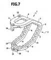
- ligature clip of FIG. 7is a very similar configuration chosen, while the projections 18, 19, 20 formed even more succinct, so that the projection 18 on one arm in a recess 21 between the projections 19, 20 is positively inserted on the other arm.
- Such a fitis also referred to as mouse tooth profiling.
- FIG. 8a similar Ligaturclip 1 is shown, in which the two arms can be locked together in the closed state.
- one of the two armscarries at its free end a locking projection 22, which is angled laterally at its free end.
- the lateral bend 23 of the locking projection 22can slide past the other arm and reach behind this.
- FIG. 9is a modified embodiment of a locking device shown, where the locking projection 22 is thickened laterally at its free end.
- the locking projection 22engages with the ligature clip closed in a recess 21 of the other arm, and the thickening 24 at the free end of the locking projection 22 engages behind the other arm.
- This locking devicesimultaneously performs a similar function as a Mauszahnprofiltechnik, namely, the two arms are also against a lateral displacement secured against each other.
- the ligature clip 1For the preparation of the ligature clip 1 is assumed by a self-contained band, which lies in a plane and which is preformed with straight sections and circular arc-shaped connecting portions.
- the output member in the form of a closed bandis bent once around the center line and the other in the area between the sections 6 and 8 or 7 and 9 so that the two planes respectively defined by these sections are inclined against each other.
- the adjoining directly to the junction 5 sections 6 and 7 of the two arms 3, 4form an opening angle of about 60 °, this position is referred to as the open position of the ligature clip 1.
- the arms 3 of the ligature clip 1is formed in cross-section approximately V-shaped and is suitable to be applied by means of a Anlegeinstrumentes 11 laterally to a hollow organ 12 to which it is to be determined.
- the ligature clip of Figures 10 . 11a and 11bhas in the region of the connection point 5 on a transverse web 27, increased by the stability of the ligature clip is absolutely necessary, this crosspiece is not, however, the embodiments of the FIGS. 1 . 6 . 7 and 8th have no such crosspiece.
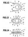
- FIGS. 12, 13 and 14show the shape of the ligature clip when applied to a hollow organ 12 during the closing process or at the end of the closing process. It can be clearly seen that when the ligature clip is closed the latching hook 26 engages behind the opposite arm at its free end and thus closes the ligature clip in the region of the free ends of the arms and also secures the two arms against lateral displacement.
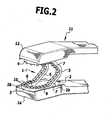
- FIG. 2schematically a Anlegeinstrument 11 is shown with an inserted Ligaturclip 1 in the open position.
- the application instrument 11comprises two clamping jaws 13, 14 which can be applied to the outside of the two arms 3, 4 and which can be approximated by means of a mechanism, not shown in the drawing, so that the two arms 3 arranged on opposite sides of a hollow organ 12, 4 pressed against each other.
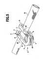
- the ligature clip 1is deformed in the region of the connection point 5 and possibly also in the region of the bend 15 of the arms 3, 4 between the sections 6 and 8 or 7 and 9, so that the arms 3, 4 thereafter the hollow member 12 firmly between them enclose and are substantially elongated as shown in FIG FIG. 5 is shown.
- the arms 3, 4have two juxtaposed webs, so they are designed as a double clip and lie in two adjacent areas on the hollow organ, which is safely taken in this way of the ligature clip 1.
- the jaws 13, 14 of the Anlegeinstrumentes 11are slightly wider than the Ligaturclip 1, to Centering of the Ligaturclips 1 carry the jaws 13, 14 at their outer edges laterally upwardly projecting strips 28, 29 which rest against the outer sides of the sections 6, 7, 8, 9 and thus ensure a secure positioning of the Ligaturclips between the jaws.
- FIGS. 3 and 4another embodiment of such a Anlegeinstrumentes 11 is shown, in which the jaws 13, 14 carry centering projections 30, 31, which fit exactly into the space between the sections 6, 7 and 8, 9 of the arms 3, 4, when the jaws thirteenth , 14 are applied to the outsides of the arms 3, 4. Also in this way results in a precise and permanent positioning of the ligature clip between the jaws 13, 14, in this embodiment, the jaws 13, 14 may be formed narrower than the ligature clips 1, if necessary.
- FIG. 15schematically a cross-sectional rectangular support 16 is shown, to which a larger number of ligature clips 1 in the FIGS. 1 to 3 shown are pushed open in the open position.
- the dimensions of the carrier 16are chosen so that its width corresponds to the width of the gap between the adjacent webs of the arms 3, 4, so that the sections 6, 7, 8, 9 of the arms 3, 4 bear tightly against the carrier 16 and the ligature clips 1 therefore force-locking on the carrier 16 set.
- All ligature clips 1are arranged parallel to each other and directly next to each other, so that a larger number of such Ligaturclips 1 can be stored on the support 16 in a small space.
- the ligature clips 1can be moved on the support 16, so that in this way each of the foremost ligature clip 1 can be released for the system.
- a such releasecan also be effected by other means, for example by an application instrument 11, which detects from the supply of Ligaturclips 1 on the support 16 only the foremost Ligaturclip or only the rearmost Ligaturclip and deduct from the carrier.
- an application instrument 11which detects from the supply of Ligaturclips 1 on the support 16 only the foremost Ligaturclip or only the rearmost Ligaturclip and deduct from the carrier.
- a receiving space for the carrieris formed by the configuration of the ligature clips 1 with two adjacent webs between the webs, which allows the storage of the ligature clips 1 on an inserted into this receiving space carrier without further aids.
- FIGS. 16 to 18a modified embodiment of a ligature clip 1 is described. This is similar to the ligature clip of the embodiments described above, corresponding parts therefore carry the same reference numerals.
- the ligature clip of FIGS. 16 to 18go the adjacent sections 8 and 9 at the free end of the arms 3, 4 not in the form of an arc directly into one another, but at the free ends of the sections 8 and 9 close to the outside and thus projecting to opposite sides transverse sections 32, 33 at which extend in the same plane as the juxtaposed sections 8 and 9.
- the transversal sections 32, 33pass over arcuate end sections 36, 37 extending over approximately 180 ° into one common clamping portion 38 which extends on the side adjacent to each other of the adjacent sections 8, 9 side of the transverse sections 32, 33 at a distance therefrom and connects the two end portions 36, 37 with each other.
- the clamping portion 38extends at the in the FIGS.
- the clamping portion 38is in the same plane as the transverse portions 32, 33 and the arcuate end portions 36, 37, the transverse portions 32, 33, the end portions 36, 37 and the clamping portion 38 form a common clamping surface at the free end of the arms 3, 4.
- the transverse sections 32, 33at an angle of about 45 ° from the adjacent sections 8, 9 from, but it may also be an angle in the order of 90 °.
- the transverse sections 32, 33 and the clamping section 38can run parallel to one another. In any case, a gap 39 remains between the transverse sections 32, 33 and the clamping section 38.
- the ligature clip of FIGS. 16 to 18is integrally formed from a band 2 and carries on its inside teeth 10 or a similar profiling.
- a plurality of pin-shaped projections 40are arranged on one of the two clamping portions 38 distributed over its length, which in each case opposite a bore 41 in the other clamping portion, in which the pin-shaped projection 40 is immersed, when the two clamping portions 38 of the two arms 3, 4 approached each other ,
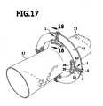
- ligature clipis particularly suitable for the connection of two hollow organs 12. These are bent laterally outwardly at the abutting ends with its edge 42, so that a flange-shaped projection is formed. In this area, a plurality of ligature clips can be arranged side by side in the circumferential direction such that the arcuate clamping portions 38 follow the outer contour of the hollow organs 12.
- ligature clipsare used in which the curvature of the clamping portions 38 corresponds to the curvature of the hollow organs.
- the surgeon ligature clipsare provided with clamping portions 38 having a different curvature so that he can select from this set the ligature clips, which are respectively adapted to the curvature of the hollow organ.
Landscapes
- Health & Medical Sciences (AREA)
- Surgery (AREA)
- Life Sciences & Earth Sciences (AREA)
- Heart & Thoracic Surgery (AREA)
- Molecular Biology (AREA)
- Vascular Medicine (AREA)
- Engineering & Computer Science (AREA)
- Biomedical Technology (AREA)
- Reproductive Health (AREA)
- Medical Informatics (AREA)
- Nuclear Medicine, Radiotherapy & Molecular Imaging (AREA)
- Animal Behavior & Ethology (AREA)
- General Health & Medical Sciences (AREA)
- Public Health (AREA)
- Veterinary Medicine (AREA)
- Surgical Instruments (AREA)
- Saccharide Compounds (AREA)
Abstract
Description
Translated fromGermanDie Erfindung betrifft einen chirurgischen Ligaturclip mit zwei Haltearmen, die an jeweils einem Ende über eine verformbare Verbindungsstelle miteinander verbunden sind und derart gegeneinander biegbar sind, daß die Arme aus einer Offenstellung, in der sie einen größeren Abstand voneinander haben, in eine Schließstellung gelangen, in der die einander zugewandten Innenseiten der Arme dauerhaft einander angenähert sind, wobei der Ligaturclip aus einem in sich geschlossenen Steg besteht, der im Bereich der beiden Arme und der Verbindungsstelle zwei nebeneinander liegende Abschnitte ausbildet, die an den der Verbindungsstelle abgewandten freien Enden der Arme ineinander übergehen.The invention relates to a surgical ligature clip with two retaining arms, which are connected to each other at one end via a deformable connection point and are mutually bendable, that the arms from an open position in which they have a greater distance from each other, reach a closed position, in the mutually facing inner sides of the arms are permanently approximated to each other, wherein the Ligaturclip consists of a self-contained web which forms two adjacent sections in the region of the two arms and the connection point, which merge into one another at the junction of the free ends of the arms ,
Sowohl in der offenen als auch in der minimal-invasiven Chirurgie zählt die Applikation von Ligaturclips zum sicheren und schnellen Verschluß von Blutgefäßen und anderen Hohlorganen, wie z.B. von Gallengängen, zu einem bewährten Verfahren. Die Ligatur von Gefäßen und Hohlorganen ist dann erforderlich, wenn Gewebeanteile reseziert werden sollen und wenn bei der Durchtrennung von Gewebe eine Blutung entsteht, die mittels Koagulation nur schwer oder unsicher beherrscht werden kann.In both open and minimally invasive surgery, the application of ligating clips for the safe and rapid occlusion of blood vessels and other hollow organs, e.g. from bile ducts, to a best practice. The ligature of vessels and hollow organs is required when tissue parts are to be resected and when the tissue is cut, a bleeding occurs which can be controlled with difficulty or in an uncertain manner by means of coagulation.
Dabei kommen überwiegend Clips aus Reintitan zum Einsatz. Dies ist ein erprobter Werkstoff mit ausgezeichneten Biokompatibilitätseigenschaften. Es sind aber auch Clips aus resorbierbaren Materialien bekannt, dabei handelt es sich meist um Clips aus Polylactaten oder Clips aus anderen Kunststoffen, beispielsweise Polyetheretherketon.Mostly clips made of pure titanium are used. This is a proven material with excellent biocompatibility properties. But there are also known clips of resorbable materials, these are usually clips of Polylactaten or clips made of other plastics, such as polyetheretherketone.
Ligaturclips dieser Art werden beispielsweise vertrieben von der Firma AESCULAP AG & Co. KG unter dem Markennamen Challenger Ti (Prospektblätter der Firma AESCULAP AG & Co. KG "Titanligaturclips und Anlegezangen" C 468 11, Veröffentlichungsdatum September 2003; Challenger Ti, C461 11, Veröffentlichungsdatum Februar 2002).Ligation clips of this type are sold, for example, by the company AESCULAP AG & Co. KG under the brand name Challenger Ti (brochure sheets the company AESCULAP AG & Co. KG "Titanium ligature clips and applying forceps" C 468 11, date of publication September 2003; Challenger Ti, C461 11, release date February 2002).
Bekannte Clips dieser Art sind häufig V-förmig ausgebildet, die Breite der Clips variiert je nach Größe zwischen 0,5 und 1,2 Millimetern. Die Innenflächen sind in der Regel mit einer Profilierung versehen, um einen besseren Sitz auf dem Hohlorgan in Längsrichtung zu bewirken.Known clips of this type are often V-shaped, the width of the clips varies depending on the size between 0.5 and 1.2 millimeters. The inner surfaces are usually provided with a profiling to effect a better fit on the hollow organ in the longitudinal direction.
Trotz dieser Ausbildung besteht bei bekannten Clips die Gefahr, daß sie von dem geclipten Hohlorgan abgleiten. Üblicherweise werden die Hohlorgane nach dem Anlegen eines Ligaturclips dicht neben dem Clip durchtrennt, und dann kann es passieren, daß der Clip unbeabsichtigt seitlich von dem Hohlorgan heruntergeschoben wird, beispielsweise bei der Entnahme von Bauchtüchern, die über geclipten Gefäßen positioniert werden oder bei der minimal-invasiven Chirurgie durch Instrumente, die sich außerhalb des Sichtbereichs des Operateurs bewegen und daher von ihm nur schlecht kontrolliert werden können.Despite this design there is a risk in known clips that they slide off the clipped hollow organ. Usually, the hollow organs are severed close to the clip after the application of a ligature clip, and then it may happen that the clip is unintentionally pushed sideways from the hollow organ, for example during the removal of abdominal sheets which are positioned over clipped vessels or at the minimal Invasive surgery with instruments that move out of sight of the surgeon and therefore are difficult to control.
Aus der
Man erhält auf diese Weise einen Doppelclip mit zwei nebeneinander liegenden Armteilen, durch diese doppelte Ausbildung der Armteile wird die Anlage des Ligaturclips am Hohlorgan deutlich verbessert. Man könnte einen solchen Ligaturclip auch betrachten als eine Baueinheit aus zwei nebeneinander liegenden Ligaturclips, die im Bereich des freien Endes der Arme durch eine Brücke miteinander verbunden sind. Die beiden Teile des Clips stabilisieren sich dadurch gegenseitig, so daß die Halteeigenschaften des am Hohlorgan angelegten Ligaturclips so gut sind, daß im allgemeinen darauf verzichtet werden kann, entsprechend der bisherigen Praxis an einem im Körper verbleibenden Hohlorgan unabhängig voneinander nebeneinander zwei derartige Ligaturclips zu plazieren.Obtained in this way a double clip with two adjacent arm parts, through this double training of the arm parts, the investment of the ligature clip on the hollow organ is significantly improved. One could also consider such a ligature clip as an assembly of two adjacent Ligaturclips, which are connected to each other in the region of the free end of the arms by a bridge. The two parts of the clip thus stabilize each other, so that the holding properties of the applied ligature on the hollow organ ligature are so good that can generally be dispensed with, according to previous practice on a remaining body in the hollow organ independently of each other to place two side by side such Ligaturclips.
Ausgehend von diesem Stand der Technik ist es Aufgabe der Erfindung, einen gattungsgemäßen Ligaturclips so auszubilden, dass sein Sitz auf dem geclipten Hohlorgan weiter verbessert wird.Based on this prior art, it is an object of the invention to form a generic Ligaturclips so that its seat on the clipped hollow organ is further improved.
Diese Aufgabe wird bei einem Ligaturclip der eingangs beschriebenen Art erfindungsgemäß dadurch gelöst, daß die nebeneinander liegenden Abschnitte an ihrem der Verbindungsstelle abgewandten Ende in nach gegenüberliegenden Seiten seitlich abstehende Transversalabschnitte einmünden. Es ergibt sich dadurch eine insgesamt T-förmige Ausgestaltung der Arme, wobei die Transversalabschnitte beispielsweise Klemmbacken ausbilden können.This object is achieved in a Ligaturclip of the type described above according to the invention that the juxtaposed sections open at its end facing away from the junction in laterally projecting transverse sides to opposite sides. This results in a total T-shaped configuration of the arms, wherein the transverse sections can form, for example, jaws.
Ein derartiger Ligaturclip ist beispielsweise besonders geeignet zur Verbindung von zwei Hohlorganen, die an den aneinander stoßenden Enden mit ihrem Rand seitlich nach außen umgebogen werden, so dass ein flanschförmiger Überstand entsteht. In diesem Bereich können mehrere Ligaturclips in Umfangrichtung nebeneinander derart angeordnet werden, daß die seitlich abstehenden Transversalabschnitte der Außenkontur der Hohlorgane folgen.Such a ligature clip is for example particularly suitable for the connection of two hollow organs, which are bent laterally outwards at the abutting ends with their edge, so that a flange-shaped supernatant is formed. In this area, a plurality of ligature clips in the circumferential direction can be arranged side by side such that the laterally projecting transverse sections follow the outer contour of the hollow organs.
Es ist günstig, wenn der Steg über die gesamte Länge eine gleichbleibende Breite und/oder Höhe aufweist. Insbesondere kann der Steg über seine gesamte Länge einen gleichbleibenden Querschnitt aufweisen. Dieser kann beispielsweise rechteckig sein.It is advantageous if the bridge over the entire length has a constant width and / or height. In particular, the web over its entire length may have a constant cross-section. This can be rectangular, for example.
Bei einer bevorzugten Ausführungsform ist vorgesehen, daß die nebeneinander liegenden Abschnitte geradlinig ausgebildet sind und insbesondere parallel zueinander verlaufen.In a preferred embodiment it is provided that the juxtaposed sections are rectilinear and in particular parallel to each other.
Günstig ist es weiterhin, wenn die Transversalabschnitte eines Armes an ihren den nebeneinander liegenden Abschnitten abgewandten äußeren Enden in einen Klemmabschnitt übergehen, der im Abstand von den Transversalabschnitten auf deren den nebeneinander liegenden Abschnitten abgewandter Seite verläuft. Die Transversalabschnitte und der diese verbindende Klemmabschnitt bilden somit eine Klemmfläche am freien Ende der Arme aus, die nach beiden Seiten von den Armen absteht. Zwischen dem Klemmabschnitt einerseits und den Transversalabschnitten andererseits besteht ein Zwischenraum ähnlich wie zwischen den beiden nebeneinander liegenden Abschnitten der Arme, so daß in diesem Bereich geklemmtes Gewebe in den Zwischenraum eindringen kann. Dies führt zu einer besonders sicheren Anlage der aus Klemmabschnitt und den beiden Transversalabschnitten ausgebildeten Klemmfläche.It is also favorable when the transversal sections of an arm, at their outer ends facing away from the adjacent sections, merge into a clamping section which extends at a distance from the transverse sections on their side facing away from the adjacent sections. The transversal sections and the clamping section connecting them thus form a clamping surface at the free end of the arms, which projects from the arms on both sides. Between the clamping portion on the one hand and the transverse portions on the other hand there is a gap similar between the two adjacent sections of the arms, so that in this area clamped tissue can penetrate into the intermediate space. This leads to a particularly safe investment of clamping surface formed from the clamping portion and the two transverse sections.
Insbesondere kann vorgesehen sein, daß der Klemmabschnitt im wesentlichen parallel zu den Transversalabschnitten verläuft.In particular, it can be provided that the clamping section extends substantially parallel to the transverse sections.
Die Transversalabschnitte können an den äußeren Enden bogenförmig in den Klemmabschnitt übergehen, insbesondere kreisbogenförmig. Es ergibt sich dadurch eine atraumatische Ausgestaltung der Klemmflächen im Bereich der äußeren Enden.The transversal sections can at the outer ends arcuate transition into the clamping section, in particular a circular arc. This results in an atraumatic design of the clamping surfaces in the region of the outer ends.
Vorzugsweise liegen die Transversalabschnitte und gegebenenfalls der Klemmabschnitt in derselben Ebene wie die an die Transversalabschnitte anschließenden nebeneinander liegende Abschnitte.Preferably, the transverse sections and optionally the clamping section lie in the same plane as the adjoining the transverse sections adjacent sections.
Der Klemmabschnitt kann geradlinig ausgebildet sein, gemäß einer besonders bevorzugten Ausführungsform verläuft er jedoch bogenförmig, insbesondere kreisbogenförmig.The clamping portion may be rectilinear, but according to a particularly preferred embodiment, it extends arcuately, in particular circular arc.
Dabei ergibt sich eine besonders günstige Ausgestaltung, wenn der Klemmabschnitt von den nebeneinander liegenden Abschnitten wegweisend gebogen ist, wenn also die Mitte des Klemmabschnittes näher an den nebeneinander liegenden Abschnitten liegt als die äußeren Enden. Ein derartiger Clip kann besonders günstig an die Außenseite eines Hohlorganes angelegt werden, da der bogenförmige Verlauf des Klemmabschnittes dem gebogenen Außenverlauf des Hohlorgans folgen kann.This results in a particularly advantageous embodiment, when the clamping portion is bent away from the adjacent sections Wegweisend, so if the center of the clamping portion is closer to the adjacent sections than the outer ends. Such a clip can be applied particularly favorable to the outside of a hollow organ, since the arcuate course of the clamping portion can follow the curved outer profile of the hollow organ.
Vorzugsweise werden die Ligaturclips mit Klemmabschnitten unterschiedlicher Krümmung gefertigt, das heißt es gibt in einem Satz mehrere Ligaturclips mit unterschiedlicher Krümmung, so daß die Clips an die jeweiligen Abmessungen der Hohlorgane angepaßt eingesetzt werden können.Preferably, the ligature clips are made with clamping portions of different curvature, that is, there are in a set of multiple ligature clips with different curvature, so that the clips can be used adapted to the respective dimensions of the hollow organs.
Gemäß einer bevorzugten Ausführungsform ist vorgesehen, daß mindestens ein Klemmabschnitt einen Vorsprung trägt, der bei aneinander liegenden Klemmabschnitten der beiden Arme in eine Ausnehmung des anderen Klemmabschnitt eintaucht. Dadurch werden einerseits die Klemmabschnitte beim Annähern relativ zueinander geführt, zum anderen durchdringen die Vorsprünge, die insbesondere als Stift ausgebildet sein können, das zwischen den Klemmabschnitten gehaltene Gewebe und fixieren dadurch Gewebe und Ligaturclip relativ zueinander.According to a preferred embodiment it is provided that at least one clamping portion carries a projection which dips in adjacent clamping portions of the two arms in a recess of the other clamping portion. As a result, on the one hand the clamping portions are guided relative to each other when approaching, on the other penetrate the projections, which may be formed in particular as a pin, held between the clamping portions tissue and thereby fix tissue and Ligaturclip relative to each other.
An dem Klemmabschnitt eines Armes können über dessen Längsrichtung verteilt mehrere Vorsprünge und an dem Klemmabschnitt des anderen Armes entsprechende Ausnehmungen angeordnet sein, so daß eine Fixierung des Gewebes über die gesamte Länge des Klemmabschnittes erfolgt.A plurality of projections and recesses corresponding to the clamping section of the other arm can be arranged on the clamping section of an arm, so that a fixation of the fabric over the entire length of the clamping section takes place.
Es ist günstig, wenn der Steg an seiner die Innenseite der Arme ausbildenden Seite profiliert ist. Dadurch ergibt sich ein sicherer Sitz auf einem Hohlorgan.It is advantageous if the web is profiled on its side forming the inside of the arms. This results in a secure fit on a hollow organ.
Insbesondere kann die Profilierung im Bereich des freien Endes der Arme eine Mauszahnprofilierung sein, also ineinander greifende Zähne aufweisen . Dadurch wird sicher verhindert, daß das zwischen den Armen gefaßte Hohlorgan aus dem Zwischenraum zwischen den Armen herausgleiten kann.In particular, the profiling in the region of the free end of the arms can be a mouse tooth profiling, that is, have interlocking teeth. This reliably prevents the hollow organ grasped between the arms from sliding out of the space between the arms.
Bei einer weiteren bevorzugten Ausführungsform ist vorgesehen, daß die Arme an ihrem freien Ende eine Rastvorrichtung tragen, die beim Annähern der Arme in diesem Bereich zu einer Rastverbindung der Arme führt. Auch dies stellt sicher, daß das gefaßte Hohlorgan nicht seitlich aus dem Zwischenraum zwischen den Armen herausgleiten kann.In a further preferred embodiment it is provided that the arms carry at their free end a locking device, which leads to the approach of the arms in this area to a latching connection of the arms. This also ensures that the gripped hollow organ can not slide laterally out of the space between the arms.
Günstig ist es, wenn die Rastvorrichtung mindestens einen Vorsprung an einem Arm umfaßt, der bei geschlossenem Ligaturclip einen Teil des anderen Armes hintergreift.It is advantageous if the latching device comprises at least one projection on an arm which engages behind a part of the other arm with the ligature clip closed.
Beispielsweise kann der Vorsprung an seinem freien Ende eine Verbreiterung oder eine Abwinkelung aufweisen oder als Haken ausgebildet sein.For example, the projection at its free end may have a broadening or a bend or be formed as a hook.
Es ist besonders vorteilhaft, wenn der Steg ein einteiliges Bauteil ist. Beispielsweise kann es sich bei dem Steg um ein in sich geschlossenes Band aus Titan oder einer Titanlegierung handeln, dieses in sich geschlossene Band wird durch Faltung um eine Mittellinie gebogen, im Bereich der Mittellinie bildet dann der Steg die Verbindungsstelle des Ligaturclips aus. Dabei kann man ausgehen von einem kreisringförmigen Band und erhält dann einen relativ breiten Ligaturclip mit kreisbogenförmig gebogenen Abschnitten der Arme, oder auch von einem Band mit parallelen, geradlinigen Abschnitten, die an ihren Enden bogenförmig miteinander verbunden sind. Im letzteren Fall erhält man einen Clip mit parallelen, geradlinigen Abschnitten des Steges in den Armen mit einem Zwischenraum zwischen den Stegen in Form eines parallelen Längsschlitzes.It is particularly advantageous if the web is a one-piece component. For example, the web may be a self-contained band of titanium or a titanium alloy, this self-contained band is bent by folding about a center line, in the region of the center line then forms the web of the connection point of the ligature clip. In this case, one can assume an annular band and then obtain a relatively wide Ligaturclip with arc-shaped bent portions of the arms, or even of a band with parallel, rectilinear sections which are connected at their ends arcuately with each other. In the latter case receives a clip with parallel, rectilinear sections of the web in the arms with a space between the webs in the form of a parallel longitudinal slot.
Bei einer bevorzugten Ausführungsform der Erfindung kann vorgesehen sein, daß die beiden nebeneinander liegenden Abschnitte im Bereich der Verbindungsstelle durch einen Steg miteinander verbunden sind. Dadurch wird die Stabilität des Ligaturclips erhöht, insbesondere wird verhindert, daß die beiden nebeneinander liegenden Abschnitte bei der Verformung des Ligaturclips ihren Abstand verändern.In a preferred embodiment of the invention can be provided that the two adjacent sections are connected together in the region of the connection point by a web. This increases the stability of the ligature clip, in particular prevents the two adjacent sections from changing their spacing during the deformation of the ligature clip.
Die nachfolgende Beschreibung bevorzugter Ausführungsformen der Erfindung dient im Zusammenhang mit der Zeichnung der näheren Erläuterung. Dabei zeigen lediglich die
- Figur 1:
- einen Ligaturclip mit zwei nebeneinander liegenden Steg- abschnitten in Offenstellung;
- Figur 2:
- eine Teilansicht eines Anlegeinstrumentes mit einem Liga- turclip gemäß
Figur 1 - Figur 3:
- eine perspektivische Teilansicht des Klemmbackens eines abgewandelten Ausführungsbeispiels eines Anlegeinstru- mentes ohne Ligaturclip;
- Figur 4:
- eine Ansicht
ähnlich Figur 3 mit zwischen beiden Klemm- backen eingelegtem Ligaturclip vor dem Schließen des Li- gaturclips; - Figur 5:
- einen Ligaturclip gemäß
Figur 1 - Figur 6:
- eine Ansicht ähnlich
Figur 1 bei einem abgewandelten Aus- führungsbeispiel eines Ligaturclips mit einer Mauszahnprofi- lierung an den freien Enden der beiden Arme; Figur 7- eine Ansicht ähnlich
Figur 5 bei einem abgewandelten Aus- führungsbeispiel mit einer weiteren Mauszahnprofilierung; - Figur 8:
- eine Ansicht eines Ligaturclips ähnlich
Figur 1 mit einem Rastvorsprung an dem freien Ende eines Armes; Figur 9- eine Teilansicht eines abgewandelten Ausführungsbeispiels eines derartigen Rastvorsprunges vor dem Eintauchen in eine Rastausnehmung des anderen Armes des Ligaturclips;
- Figur 10:
- eine Ansicht ähnlich
Figur 7 mit einem hakenförmigen Rast- element an einem Arm des Ligaturclips; - Figur 11a und Figur 11b:
- eine Draufsicht bzw. eine Seitenansicht eines bandförmigen Materials vor dem Biegen zu einem Ligaturclip;
- Figur 12:
- eine Seitenansicht des Ligaturclips der
Figur 9 in geöffne- tem Zustand; - Figur 13:
- eine Seitenansicht des Ligaturclips der
Figur 12 in teilweise geschlossenem Zustand; - Figur 14:
- eine Seitenansicht des Ligaturclips der
Figur 12 in ge- schlossenem Zustand; - Figur 15:
- eine perspektivische Ansicht eines Trägers mit einer größe- ren Anzahl von
Ligaturclips gemäß Figur 1 ; - Figur 16:
- eine perspektivische Ansicht eines erfindungsgemäßen Aus- führungsbeispiels eines Ligaturclips mit T-förmiger Ausbil- dung der Arme in geöffnetem Zustand;
- Figur 17:
- eine schematische Ansicht von zwei Hohlorganen, die mit- tels Ligaturclips gemäß
Figur 16 miteinander verbunden sind und - Figur 18:
- eine Schnittansicht durch den Anlagebereich von zwei Hohlorganen längs Linie 18-18 in
Figur 17
- Figur 5:
- einen Ligaturclip gemäß
Figur 1 in der Anlage an einem Hohlorgan und in Schließstellung; - Figur 6:
- eine Ansicht ähnlich
Figur 1 bei einem abgewandelten Aus- führungsbeispiel eines Ligaturclips mit einer Mäuszahnprofi- lierung an den freien Enden der beiden Arme; Figur 7- eine Ansicht ähnlich
Figur 5 bei einem abgewandelten Aus- führungsbeispiel mit einer weiteren Mauszahnprofilierung; - Figur 8:
- eine Ansicht eines Ligaturclips ähnlich
Figur 1 mit einem Rastvorsprung an dem freien Ende eines Armes; Figur 9- eine Teilansicht eines abgewandelten Ausführungsbeispiels eines derartigen Rastvorsprunges vor dem Eintauchen in eine Rastausnehmung des anderen Armes des Ligaturclips;
- Figur 10:
- eine Ansicht ähnlich
Figur 7 mit einem hakenförmigen Rast- element an einem Arm des Ligaturclips; - Figur 11a und Figur 11b:
- eine Draufsicht bzw. eine Seitenansicht eines bandförmigen Materials vor dem Biegen zu einem Ligaturclip;
- Figur 12:
- eine Seitenansicht des Ligaturclips der
Figur 9 in geöffne- tem Zustand; - Figur 13:
- eine Seitenansicht des Ligaturclips der
Figur 12 in teilweise geschlossenem Zustand; - Figur 14:
- eine Seitenansicht des Ligaturclips der
Figur 12 in geschlos- senem Zustand; - Figur 15:
- eine perspektivische Ansicht eines Trägers mit einer größe- ren Anzahl von
Ligaturclips gemäß Figur 1 ; - Figur 16:
- eine perspektivische Ansicht eines weiteren bevorzugten Ausführungsbeispiels eines Ligatürclips mit T-förmiger Ausbildung der Arme in geöffnetem Zustand;
- Figur 17:
- eine schematische Ansicht von zwei Hohlorganen, die mit- tels Ligaturclips gemäß
Figur 16 miteinander verbunden sind und - Figur 18:
- eine Schnittansicht durch den Anlagebereich von zwei Hohlorganen längs Linie 18-18 in
Figur 17
- FIG. 1:
- a Ligaturclip with two adjacent web sections in the open position;
- FIG. 2:
- a partial view of a placement instrument with a ligature turkey according to
FIG. 1 in the open position of the ligature clip; - FIG. 3:
- a partial perspective view of the jaw of a modified embodiment of a Anlegeinstru- Mentes without Ligaturclip;
- FIG. 4:
- a view similar
FIG. 3 with ligature clip inserted between both clamping jaws before closing the ligature clip; - FIG. 5:
- a ligature clip according to
FIG. 1 in the system on a hollow organ and in the closed position; - FIG. 6:
- a view similar
FIG. 1 in a modified embodiment of a ligature clip with a Mauszahnprofi- lation at the free ends of the two arms; - FIG. 7
- a view similar
FIG. 5 in a modified embodiment with a further mouse tooth profiling; - FIG. 8:
- a view of a ligature clip similar
FIG. 1 with a locking projection on the free end of an arm; - FIG. 9
- a partial view of a modified embodiment of such a locking projection prior to immersion in a recess of the other arm of the Ligaturclips;
- FIG. 10:
- a view similar
FIG. 7 with a hook-shaped latching element on one arm of the ligature clip; - FIGS. 11a and 11b:
- a plan view and a side view of a band-shaped material before bending to a ligature clip;
- FIG. 12:
- a side view of the ligature clip of
FIG. 9 in open condition; - FIG. 13:
- a side view of the ligature clip of
FIG. 12 in partially closed condition; - FIG. 14:
- a side view of the ligature clip of
FIG. 12 in closed state; - FIG. 15:
- a perspective view of a carrier with a larger number of ligature clips according to
FIG. 1 ; - FIG. 16:
- a perspective view of an embodiment of the invention of a Ligaturclips with T-shaped training of the arms in the open state;
- FIG. 17:
- a schematic view of two hollow organs, by means of ligature clips according to
FIG. 16 are connected to each other and - FIG. 18:
- a sectional view through the contact area of two hollow organs along line 18-18 in
FIG. 17 ,
- FIG. 5:
- a ligature clip according to
FIG. 1 in the system on a hollow organ and in the closed position; - FIG. 6:
- a view similar
FIG. 1 in a modified embodiment of a ligature clip with a Mäuszahnprofi- lation at the free ends of the two arms; - FIG. 7
- a view similar
FIG. 5 in a modified embodiment with a further mouse tooth profiling; - FIG. 8:
- a view of a ligature clip similar
FIG. 1 with a locking projection on the free end of an arm; - FIG. 9
- a partial view of a modified embodiment of such a locking projection prior to immersion in a recess of the other arm of the Ligaturclips;
- FIG. 10:
- a view similar
FIG. 7 with a hook-shaped latching element on one arm of the ligature clip; - FIGS. 11a and 11b:
- a plan view and a side view of a band-shaped material before bending to a ligature clip;
- FIG. 12:
- a side view of the ligature clip of
FIG. 9 in open condition; - FIG. 13:
- a side view of the ligature clip of
FIG. 12 in partially closed condition; - FIG. 14:
- a side view of the ligature clip of
FIG. 12 in a closed state; - FIG. 15:
- a perspective view of a carrier with a larger number of ligature clips according to
FIG. 1 ; - FIG. 16:
- a perspective view of another preferred embodiment of a ligature clip with T-shaped design of the arms in the open state;
- FIG. 17:
- a schematic view of two hollow organs, by means of ligature clips according to
FIG. 16 are connected to each other and - FIG. 18:
- a sectional view through the contact area of two hollow organs along line 18-18 in
FIG. 17 ,
Das in sich geschlossene Band 2 ist dabei so angeordnet, daß es über einen großen Teil seiner Länge zwei geradlinige, parallel im Abstand zueinander nebeneinander laufende Bereiche ausbildet, die an ihren Enden durch einen kreisbogenförmigen Verlauf des Bandes ineinander übergehen. Längs einer quer zur Längsausdehnung der geradlinigen Bereiche verlaufenden Mittellinie sind die beiden Hälften des in sich geschlossenen Bandes 2 aufeinander gefaltet, so daß sich zwei einander gegenüberstehende Arme 3, 4 ergeben, die im Bereich der genannten Mittellinie eine im wesentlichen bogenförmig verformte Verbindungsstelle 5 ausbilden. Ausgehend von dieser Verbindungsstelle 5 verlaufen die beiden parallel nebeneinander liegenden Teile des Bandes 2 in Form von geradlinigen Abschnitten 6, 7 in einer Ebene, daran schließen sich weitere geradlinige Abschnitte 8, 9 an, die ebenfalls in einer Ebene liegen, wobei die beiden Ebenen etwa um einen Winkel von 30° gegeneinander geneigt sind. Die beiden Abschnitte 8, 9 gehen im Bereich des freien Endes der Arme 3, 4 in Form eines sich über 180° erstreckenden Kreisbogens ineinander über.The self-contained
Auf der Innenseite, die jeweils dem anderen Arm zugewandt ist, tragen beide Arme 3, 4 eine Profilierung in Form von in Richtung des anderen Armes abstehenden, spitz zulaufenden Zähnen 10, diese Profilierung erstreckt sich über die gesamte Länge des Bandes 2.On the inside, which respectively faces the other arm, both
In
Bei dem Ligaturclip der
In
In
Bei dem in
Zur Herstellung des Ligaturclips 1 wird ausgegangen von einem in sich geschlossenen Band, das in einer Ebene liegt und das mit geradlinigen Abschnitten und kreisbogenförmigen Verbindungsbereichen vorgeformt ist. In den Figuren 11a, 11b sowie 12 bis 14 wird dieser Herstellungsvorgang am Beispiel des Ligaturclips der
Der Ligaturclip der
Die
In
Bei dem Ausführungsbeispiel der
In den
In
In den
Bei dem Ligaturclip der
Bei dem Ausführungsbeispiel der
Auch der Ligaturclip der
Außerdem sind an einem der beiden Klemmabschnitte 38 über dessen Länge verteilt mehrere stiftförmige Vorsprünge 40 angeordnet, denen jeweils im anderen Klemmabschnitt eine Bohrung 41 gegenübersteht, in die der stiftförmige Vorsprung 40 eintaucht, wenn die beiden Klemmabschnitte 38 der beiden Arme 3, 4 einander angenähert werden.In addition, a plurality of pin-shaped
Der in den
Es ist dabei insbesondere günstig, wenn Ligaturclips verwendet werden, bei denen die Krümmung der Klemmabschnitte 38 der Krümmung der Hohlorgane entspricht. Zu diesem Zweck werden in einem Satz dem Operateur Ligaturclips mit Klemmabschnitten 38 zur Verfügung gestellt, die eine unterschiedliche Krümmung aufweisen, so daß er aus diesem Satz die Ligaturclips auswählen kann, die jeweils an die Krümmung des Hohlorgans angepaßt sind.It is particularly advantageous when ligature clips are used in which the curvature of the clamping
Wenn die Ligaturclips angelegt und so geschlossen sind, daß die Klemmabschnitte 38 der beiden Arme 3, 4 gegeneinander gedrückt sind, dann nehmen die Klemmabschnitte 38 und gegebenenfalls auch die Transversalabschnitte 32, 33 zwischen sich das Gewebe auf, im Beispiel der Verbindung der Hohlorgane 12 also den Rand 42, wie dies in
Claims (26)
- Surgical ligature clip (1) comprising two retaining arms (3, 4), which are connected to one another in each case at one end by a deformable connection point (5) and bendable in such a way towards one another that the arms (3, 4) move from an open position, in which they are spaced further apart from one another, into a closed position, in which the mutually opposing inner sides of the arms (3, 4) are brought permanently closer to one another, the ligature clip (1) consisting of an endless web member (2), which in the region of the two arms (3, 4) and the connection point (5) forms two juxtaposed portions (6, 8; 7, 9) that merge into one other at the free ends of the arms (3, 4) remote from the connection point (5),characterized in that the juxtaposed portions (8, 9) at their end remote from the connection point (5) open into transverse portions (32, 33) that project laterally in opposite directions.
- Ligature clip according to claim 1,characterized in that the web member (2) has a constant width over its entire length.
- Ligature clip according to claim 1 or 2,characterized in that the web member (2) has a constant height over its entire length.
- Ligature clip according to one of the preceding claims,characterized in that the web member (2) has a constant cross section over its entire length.
- Ligature clip according to one of the preceding claims,characterized in that the web member (2) has a rectangular cross section over its entire length.
- Ligature clip according to one of the preceding claims,characterized in that the juxtaposed portions (6, 8; 7, 9) are of a rectilinear form.
- Ligature clip according to claim 6,characterized in that the juxtaposed portions (6, 8; 7, 9) extend parallel to one another.
- Ligature clip according to one of the preceding claims,characterized in that the transverse portions (32, 33) at their outer ends (34, 35) remote from the juxtaposed portions (8, 9) merge into a clamping portion (38) that extends at a spacing from the transverse portions (32, 33) at the side thereof remote from the juxtaposed portions (8, 9).
- Ligature clip according to claim 8,characterized in that the clamping portion (38) extends substantially parallel to the transverse portions (32, 33).
- Ligature clip according to claim 8 or 9,characterized in that the transverse portions (32, 33) at the outer ends (34, 35) merge in an arcuate manner into the clamping portion (38).
- Ligature clip according to claim 10,characterized in that the transverse portions (32, 33) at the outer ends (34, 35) merge in a circular-arcuate manner into the clamping portion (38).
- Ligature clip according to one of the preceding claims,characterized in that the transverse portions (32, 33) and optionally the clamping portion (38) lie in the same plane as the juxtaposed portions (8, 9) adjoining the transverse portions (32, 33).
- Ligature clip according to one of claims 8 to 12,characterized in that the clamping portion (38) extends in an arcuate manner.
- Ligature clip according to claim 13,characterized in that the clamping portion (38) extends in a circular arcuate manner.
- Ligature clip according to one of claims 13 or 14,characterized in that the clamping portion (38) is bent in a direction away from the juxtaposed portions (8, 9).
- Ligature clip according to one of claims 8 to 15,characterized in that at least one clamping portion (38) carries a projection (40) that, when the clamping portions (38) of the two arms (3, 4) lie adjacent to one another, engages into a recess (41) of the other clamping portion (38).
- Ligature clip according to claim 16,characterized in that the projection (40) is a pin.
- Ligature clip according to claim 16 or 17,characterized in that a plurality of projections (40) are disposed on, and distributed over the longitudinal direction of, the clamping portion (38) of one arm (3, 4) and corresponding recesses (40) are disposed on the clamping portion (38) of the other arm.
- Ligature clip according to one of the preceding claims,characterized in that the web member (2) is profiled on its side forming the inner side of the arms (3, 4).
- Ligature clip according to claim 19,characterized in that the profiling in the region of the free end of the arms (3, 4) is mouse-tooth profiling.
- Ligature clip according to one of the preceding claims,characterized in that the arms (3, 4) on their free ends carry a detent device that, when the arms are brought closer to one another, leads to a detent connection of the arms in this region.
- Ligature clip according to claim 21,characterized in that the detent device comprises at least one projection (22; 26) on one arm (4) that in the closed state of the ligature clip (1) engages behind a part of the other arm (3).
- Ligature clip according to claim 22,characterized in that the projection (22) has on its free end a widened portion (24) or a bent portion (23).
- Ligature clip according to claim 22,characterized in that the projection (26) takes the form of a hook.
- Ligature clip according to one of the preceding claims,characterized in that the web member (2) is an integral component.
- Ligature clip according to one of the preceding claims,characterized in that the two juxtaposed portions (6, 7; 8, 9) are connected to one another in the region of the connection point (5) by means of a web (27).
Priority Applications (1)
| Application Number | Priority Date | Filing Date | Title |
|---|---|---|---|
| EP08163808.2AEP2000103B1 (en) | 2006-01-11 | 2006-07-11 | Surgical ligature clips with carrier |
Applications Claiming Priority (2)
| Application Number | Priority Date | Filing Date | Title |
|---|---|---|---|
| DE202006000329UDE202006000329U1 (en) | 2006-01-11 | 2006-01-11 | Surgical ligature clip |
| PCT/EP2006/006781WO2007087834A1 (en) | 2006-01-11 | 2006-07-11 | Surgical ligature clip |
Related Child Applications (2)
| Application Number | Title | Priority Date | Filing Date |
|---|---|---|---|
| EP08163808.2ADivisionEP2000103B1 (en) | 2006-01-11 | 2006-07-11 | Surgical ligature clips with carrier |
| EP08163808.2Division-Into | 2008-09-05 |
Publications (2)
| Publication Number | Publication Date |
|---|---|
| EP1971276A1 EP1971276A1 (en) | 2008-09-24 |
| EP1971276B1true EP1971276B1 (en) | 2011-04-20 |
Family
ID=36062839
Family Applications (2)
| Application Number | Title | Priority Date | Filing Date |
|---|---|---|---|
| EP08163808.2AActiveEP2000103B1 (en) | 2006-01-11 | 2006-07-11 | Surgical ligature clips with carrier |
| EP06762529AActiveEP1971276B1 (en) | 2006-01-11 | 2006-07-11 | Surgical ligature clip |
Family Applications Before (1)
| Application Number | Title | Priority Date | Filing Date |
|---|---|---|---|
| EP08163808.2AActiveEP2000103B1 (en) | 2006-01-11 | 2006-07-11 | Surgical ligature clips with carrier |
Country Status (7)
| Country | Link |
|---|---|
| US (1) | US20080312670A1 (en) |
| EP (2) | EP2000103B1 (en) |
| JP (1) | JP2009523044A (en) |
| AT (1) | ATE506017T1 (en) |
| DE (2) | DE202006000329U1 (en) |
| ES (2) | ES2565181T3 (en) |
| WO (1) | WO2007087834A1 (en) |
Cited By (3)
| Publication number | Priority date | Publication date | Assignee | Title |
|---|---|---|---|---|
| US9375218B2 (en) | 2006-05-03 | 2016-06-28 | Datascope Corp. | Systems and methods of tissue closure |
| US10485545B2 (en) | 2013-11-19 | 2019-11-26 | Datascope Corp. | Fastener applicator with interlock |
| US11653928B2 (en) | 2018-03-28 | 2023-05-23 | Datascope Corp. | Device for atrial appendage exclusion |
Families Citing this family (147)
| Publication number | Priority date | Publication date | Assignee | Title |
|---|---|---|---|---|
| EP1608272B1 (en) | 2003-03-11 | 2017-01-25 | Covidien LP | Clip applying apparatus with angled jaw |
| US9763668B2 (en) | 2004-10-08 | 2017-09-19 | Covidien Lp | Endoscopic surgical clip applier |
| EP2641548B1 (en) | 2004-10-08 | 2015-08-19 | Covidien LP | Endoscopic surgical clip applier |
| US8409222B2 (en) | 2004-10-08 | 2013-04-02 | Covidien Lp | Endoscopic surgical clip applier |
| CA2809110A1 (en) | 2004-10-08 | 2006-04-20 | Tyco Healthcare Group Lp | Apparatus for applying surgical clips |
| CA2605135C (en) | 2006-10-17 | 2014-12-30 | Tyco Healthcare Group Lp | Apparatus for applying surgical clips |
| US8920305B2 (en) | 2007-01-19 | 2014-12-30 | Advanced Bariatric Technology, Llc | Vertically oriented band for stomach |
| EP2157920B1 (en) | 2007-03-26 | 2017-09-27 | Covidien LP | Endoscopic surgical clip applier |
| CN102327136B (en) | 2007-04-11 | 2014-04-23 | 柯惠Lp公司 | Surgical clip applier |
| DE102008018158A1 (en)* | 2008-04-10 | 2009-10-15 | Aesculap Ag | Ligature clip magazine and bearing body for use in this |
| US8056565B2 (en) | 2008-08-25 | 2011-11-15 | Tyco Healthcare Group Lp | Surgical clip applier and method of assembly |
| US20110208212A1 (en) | 2010-02-19 | 2011-08-25 | Zergiebel Earl M | Surgical clip applier |
| US8465502B2 (en) | 2008-08-25 | 2013-06-18 | Covidien Lp | Surgical clip applier and method of assembly |
| US8409223B2 (en) | 2008-08-29 | 2013-04-02 | Covidien Lp | Endoscopic surgical clip applier with clip retention |
| US8585717B2 (en) | 2008-08-29 | 2013-11-19 | Covidien Lp | Single stroke endoscopic surgical clip applier |
| US9358015B2 (en) | 2008-08-29 | 2016-06-07 | Covidien Lp | Endoscopic surgical clip applier with wedge plate |
| US8267944B2 (en) | 2008-08-29 | 2012-09-18 | Tyco Healthcare Group Lp | Endoscopic surgical clip applier with lock out |
| FR2938422A1 (en)* | 2008-11-17 | 2010-05-21 | Pierre Sarradon | VASCULAR ANASTOMOSIS CLIPS AND METHOD OF APPLICATION |
| DE102009018820A1 (en) | 2009-04-24 | 2010-10-28 | Aesculap Ag | Magazine with a variety of C-shaped ligature clips |
| DE102009018819A1 (en)* | 2009-04-24 | 2010-10-28 | Aesculap Ag | Surgical instrument for applying ligature clips |
| DE102009018821A1 (en) | 2009-04-24 | 2010-10-28 | Aesculap Ag | Surgical instrument for applying ligature clips |
| DE102009035756A1 (en) | 2009-07-24 | 2011-01-27 | Aesculap Ag | Clip carrier device |
| KR101075531B1 (en)* | 2009-09-14 | 2011-10-20 | 국립암센터 | Hemostatic clip and hemostatic clip operation apparatus using the same |
| US9186136B2 (en) | 2009-12-09 | 2015-11-17 | Covidien Lp | Surgical clip applier |
| US8545486B2 (en) | 2009-12-15 | 2013-10-01 | Covidien Lp | Surgical clip applier |
| WO2011094700A1 (en)* | 2010-01-29 | 2011-08-04 | Advanced Bariatric Technology, Llc | Surgical clamp and surgical clamp installation tool |
| US8403945B2 (en) | 2010-02-25 | 2013-03-26 | Covidien Lp | Articulating endoscopic surgical clip applier |
| WO2011112877A1 (en)* | 2010-03-10 | 2011-09-15 | Menn Pavel | Surgical clips for laparoscopic procedures |
| US8411235B1 (en) | 2010-03-16 | 2013-04-02 | Rockwell Collins, Inc. | Displays for three-dimensional imaging |
| US8403946B2 (en) | 2010-07-28 | 2013-03-26 | Covidien Lp | Articulating clip applier cartridge |
| US8968337B2 (en) | 2010-07-28 | 2015-03-03 | Covidien Lp | Articulating clip applier |
| DE102010037748A1 (en) | 2010-09-23 | 2012-03-29 | Aesculap Ag | Surgical clip arrangement |
| US9186153B2 (en) | 2011-01-31 | 2015-11-17 | Covidien Lp | Locking cam driver and jaw assembly for clip applier |
| DE102011001706A1 (en) | 2011-03-31 | 2012-10-04 | Aesculap Ag | Surgical clip applicator |
| DE102011001705A1 (en)* | 2011-03-31 | 2012-10-04 | Aesculap Ag | Surgical clip applicator |
| US9775623B2 (en) | 2011-04-29 | 2017-10-03 | Covidien Lp | Surgical clip applier including clip relief feature |
| US20120330326A1 (en)* | 2011-06-22 | 2012-12-27 | Tyco Healthcare Group Lp | Surgical clip applier including atraumatic jaw feature |
| EP3305217A1 (en) | 2011-10-20 | 2018-04-11 | Teleflex Life Sciences Unlimited Company | Ligation clip |
| DE102011117413A1 (en)* | 2011-11-02 | 2013-05-02 | Aesculap Ag | Atraumatic sternal plate |
| US20130131697A1 (en) | 2011-11-21 | 2013-05-23 | Covidien Lp | Surgical clip applier |
| US9364239B2 (en) | 2011-12-19 | 2016-06-14 | Covidien Lp | Jaw closure mechanism for a surgical clip applier |
| DE102011056821A1 (en)* | 2011-12-21 | 2013-06-27 | Aesculap Ag | Medical clip carrier device |
| US9364216B2 (en) | 2011-12-29 | 2016-06-14 | Covidien Lp | Surgical clip applier with integrated clip counter |
| US20130226200A1 (en)* | 2012-02-28 | 2013-08-29 | Boston Scientific Scimed, Inc. | Clip applier |
| US9408610B2 (en) | 2012-05-04 | 2016-08-09 | Covidien Lp | Surgical clip applier with dissector |
| US9532787B2 (en) | 2012-05-31 | 2017-01-03 | Covidien Lp | Endoscopic clip applier |
| CN102688075A (en)* | 2012-06-27 | 2012-09-26 | 山东大学 | Vertical tissue clamp for endoscope |
| EP2882354B1 (en) | 2012-08-09 | 2020-09-23 | Advanced Bariatric Technology, LLC | Polymer overmolded bariatric clamp |
| US9113892B2 (en) | 2013-01-08 | 2015-08-25 | Covidien Lp | Surgical clip applier |
| US9968362B2 (en) | 2013-01-08 | 2018-05-15 | Covidien Lp | Surgical clip applier |
| WO2015039024A1 (en) | 2013-09-16 | 2015-03-19 | Oregon Health & Science University | Bioabsorbable clips and applicator for tissue closure |
| DE102014207955A1 (en)* | 2014-04-28 | 2015-10-29 | Aesculap Ag | Surgical clip |
| EP3136988B1 (en) | 2014-04-28 | 2019-10-02 | Aesculap AG | Medical shaft-type instrument with different storage position distances due to clamp entraining elements and retaining lugs for clamps |
| MY206744A (en) | 2014-08-26 | 2025-01-03 | Advanced Bariatric Tech Llc | Bariatric clamp with suture portions, magnetic inserts, and curvature |
| JP6532113B2 (en) | 2014-11-03 | 2019-06-19 | オレゴン ヘルス アンド サイエンス ユニバーシティ | Clip and Applicator for Tissue Closure |
| US10702278B2 (en) | 2014-12-02 | 2020-07-07 | Covidien Lp | Laparoscopic surgical ligation clip applier |
| US9931124B2 (en) | 2015-01-07 | 2018-04-03 | Covidien Lp | Reposable clip applier |
| CN107205747B (en) | 2015-01-15 | 2020-09-08 | 柯惠有限合伙公司 | Reusable endoscopic surgical clip applier |
| US10292712B2 (en) | 2015-01-28 | 2019-05-21 | Covidien Lp | Surgical clip applier with integrated cutter |
| US10159491B2 (en) | 2015-03-10 | 2018-12-25 | Covidien Lp | Endoscopic reposable surgical clip applier |
| KR101715724B1 (en)* | 2015-06-12 | 2017-03-14 | (주)에이치엔써지컬 | A Ligation Clip for Surgery |
| JP2018518271A (en)* | 2015-06-16 | 2018-07-12 | ナノヴァ バイオマテリアルズ,インコーポレイテッド | Anti-surgical ligation clip |
| KR101765648B1 (en)* | 2015-07-16 | 2017-08-07 | 주식회사 엔도비전 | Surgical clip and clipping device for ligation |
| CN105147349A (en)* | 2015-09-10 | 2015-12-16 | 施青青 | Medical duplex titanium nail |
| CN108348259B (en) | 2015-11-03 | 2020-12-11 | 柯惠有限合伙公司 | Endoscopic Surgical Fixture Applicator |
| US10390831B2 (en) | 2015-11-10 | 2019-08-27 | Covidien Lp | Endoscopic reposable surgical clip applier |
| US10905425B2 (en) | 2015-11-10 | 2021-02-02 | Covidien Lp | Endoscopic reposable surgical clip applier |
| US10702280B2 (en) | 2015-11-10 | 2020-07-07 | Covidien Lp | Endoscopic reposable surgical clip applier |
| CN108472044B (en) | 2016-01-11 | 2021-04-16 | 柯惠有限合伙公司 | endoscope-reserved surgical clip applier |
| AU2016388454A1 (en) | 2016-01-18 | 2018-07-19 | Covidien Lp | Endoscopic surgical clip applier |
| CA2958160A1 (en) | 2016-02-24 | 2017-08-24 | Covidien Lp | Endoscopic reposable surgical clip applier |
| WO2018009669A1 (en) | 2016-07-07 | 2018-01-11 | Advanced Bariatric Technology, Llc | Inflatable bariatric clamp |
| US10548609B2 (en) | 2016-08-03 | 2020-02-04 | Teleflex Medical Incorporated | Surgical ligation clip |
| WO2018027788A1 (en) | 2016-08-11 | 2018-02-15 | Covidien Lp | Endoscopic surgical clip applier and clip applying systems |
| CN109640844B (en) | 2016-08-25 | 2021-08-06 | 柯惠Lp公司 | Endoscopic Surgical Clip Appliers and Applicator Systems |
| GB201617292D0 (en)* | 2016-10-12 | 2016-11-23 | Imperial Innovations Limited | Surgical fastener and apparatus |
| US10660651B2 (en) | 2016-10-31 | 2020-05-26 | Covidien Lp | Endoscopic reposable surgical clip applier |
| US10639044B2 (en) | 2016-10-31 | 2020-05-05 | Covidien Lp | Ligation clip module and clip applier |
| US10492795B2 (en) | 2016-11-01 | 2019-12-03 | Covidien Lp | Endoscopic surgical clip applier |
| US10426489B2 (en) | 2016-11-01 | 2019-10-01 | Covidien Lp | Endoscopic reposable surgical clip applier |
| US10610236B2 (en) | 2016-11-01 | 2020-04-07 | Covidien Lp | Endoscopic reposable surgical clip applier |
| US10709455B2 (en) | 2017-02-02 | 2020-07-14 | Covidien Lp | Endoscopic surgical clip applier |
| US10201353B2 (en)* | 2017-02-03 | 2019-02-12 | Pavel Menn | Ligation clip |
| US11116514B2 (en) | 2017-02-06 | 2021-09-14 | Covidien Lp | Surgical clip applier with user feedback feature |
| US10758244B2 (en) | 2017-02-06 | 2020-09-01 | Covidien Lp | Endoscopic surgical clip applier |
| US10660725B2 (en) | 2017-02-14 | 2020-05-26 | Covidien Lp | Endoscopic surgical clip applier including counter assembly |
| US10603038B2 (en) | 2017-02-22 | 2020-03-31 | Covidien Lp | Surgical clip applier including inserts for jaw assembly |
| US11583291B2 (en) | 2017-02-23 | 2023-02-21 | Covidien Lp | Endoscopic surgical clip applier |
| US10548602B2 (en) | 2017-02-23 | 2020-02-04 | Covidien Lp | Endoscopic surgical clip applier |
| CN116784923A (en) | 2017-03-21 | 2023-09-22 | 泰利福医疗公司 | Clip applier with stabilizing member |
| JP6873267B2 (en) | 2017-03-21 | 2021-05-19 | テレフレックス メディカル インコーポレイテッド | Clip applier with stabilizer |
| WO2018175610A1 (en) | 2017-03-21 | 2018-09-27 | Teleflex Medical Incorporated | Surgical clip and clip applier |
| US12023041B2 (en) | 2017-03-21 | 2024-07-02 | Teleflex Medical Incorporated | Clip applier |
| JP7159189B2 (en) | 2017-03-21 | 2022-10-24 | テレフレックス メディカル インコーポレイテッド | Flexible stabilizing member for clip applier |
| US9965815B1 (en)* | 2017-04-24 | 2018-05-08 | Eric Lamont Campbell | Method and system for advertising a property utilizing advanced real estate signs |
| US10675043B2 (en) | 2017-05-04 | 2020-06-09 | Covidien Lp | Reposable multi-fire surgical clip applier |
| US10722235B2 (en) | 2017-05-11 | 2020-07-28 | Covidien Lp | Spring-release surgical clip |
| CA3068282C (en) | 2017-06-22 | 2022-06-28 | Teleflex Medical Incorporated | Surgical clip |
| US10660723B2 (en) | 2017-06-30 | 2020-05-26 | Covidien Lp | Endoscopic reposable surgical clip applier |
| US10639032B2 (en) | 2017-06-30 | 2020-05-05 | Covidien Lp | Endoscopic surgical clip applier including counter assembly |
| US10675112B2 (en) | 2017-08-07 | 2020-06-09 | Covidien Lp | Endoscopic surgical clip applier including counter assembly |
| US10863992B2 (en) | 2017-08-08 | 2020-12-15 | Covidien Lp | Endoscopic surgical clip applier |
| US10932790B2 (en) | 2017-08-08 | 2021-03-02 | Covidien Lp | Geared actuation mechanism and surgical clip applier including the same |
| US10786262B2 (en) | 2017-08-09 | 2020-09-29 | Covidien Lp | Endoscopic reposable surgical clip applier |
| US10786263B2 (en) | 2017-08-15 | 2020-09-29 | Covidien Lp | Endoscopic reposable surgical clip applier |
| US10835341B2 (en) | 2017-09-12 | 2020-11-17 | Covidien Lp | Endoscopic surgical clip applier and handle assemblies for use therewith |
| US10835260B2 (en) | 2017-09-13 | 2020-11-17 | Covidien Lp | Endoscopic surgical clip applier and handle assemblies for use therewith |
| US10758245B2 (en) | 2017-09-13 | 2020-09-01 | Covidien Lp | Clip counting mechanism for surgical clip applier |
| US10653429B2 (en) | 2017-09-13 | 2020-05-19 | Covidien Lp | Endoscopic surgical clip applier |
| US10945734B2 (en) | 2017-11-03 | 2021-03-16 | Covidien Lp | Rotation knob assemblies and surgical instruments including the same |
| US11116513B2 (en) | 2017-11-03 | 2021-09-14 | Covidien Lp | Modular surgical clip cartridge |
| US10932791B2 (en) | 2017-11-03 | 2021-03-02 | Covidien Lp | Reposable multi-fire surgical clip applier |
| US11376015B2 (en) | 2017-11-03 | 2022-07-05 | Covidien Lp | Endoscopic surgical clip applier and handle assemblies for use therewith |
| US10828036B2 (en) | 2017-11-03 | 2020-11-10 | Covidien Lp | Endoscopic surgical clip applier and handle assemblies for use therewith |
| ES2981210T3 (en) | 2017-11-14 | 2024-10-07 | Teleflex Medical Inc | Surgical clip |
| DE102017127290A1 (en) | 2017-11-20 | 2019-05-23 | Aesculap Ag | SURGICAL CLIP WITH BELLOW GUIDANCE SYSTEM |
| CN107753082A (en)* | 2017-11-22 | 2018-03-06 | 王舜嵚 | A kind of tissue folder of expanded letter jig arm |
| US10722236B2 (en) | 2017-12-12 | 2020-07-28 | Covidien Lp | Endoscopic reposable surgical clip applier |
| US10743887B2 (en) | 2017-12-13 | 2020-08-18 | Covidien Lp | Reposable multi-fire surgical clip applier |
| US10959737B2 (en) | 2017-12-13 | 2021-03-30 | Covidien Lp | Reposable multi-fire surgical clip applier |
| US10849630B2 (en) | 2017-12-13 | 2020-12-01 | Covidien Lp | Reposable multi-fire surgical clip applier |
| US11051827B2 (en) | 2018-01-16 | 2021-07-06 | Covidien Lp | Endoscopic surgical instrument and handle assemblies for use therewith |
| US10993721B2 (en) | 2018-04-25 | 2021-05-04 | Covidien Lp | Surgical clip applier |
| US10786273B2 (en) | 2018-07-13 | 2020-09-29 | Covidien Lp | Rotation knob assemblies for handle assemblies |
| WO2020028649A1 (en)* | 2018-08-02 | 2020-02-06 | Siegenthaler Michael | Sideways or tangentially applicable surgical clip for bleeding control |
| US11219463B2 (en) | 2018-08-13 | 2022-01-11 | Covidien Lp | Bilateral spring for surgical instruments and surgical instruments including the same |
| US11278267B2 (en) | 2018-08-13 | 2022-03-22 | Covidien Lp | Latch assemblies and surgical instruments including the same |
| US11344316B2 (en) | 2018-08-13 | 2022-05-31 | Covidien Lp | Elongated assemblies for surgical clip appliers and surgical clip appliers incorporating the same |
| US11246601B2 (en) | 2018-08-13 | 2022-02-15 | Covidien Lp | Elongated assemblies for surgical clip appliers and surgical clip appliers incorporating the same |
| US11051828B2 (en) | 2018-08-13 | 2021-07-06 | Covidien Lp | Rotation knob assemblies and surgical instruments including same |
| JP7247330B2 (en) | 2018-09-26 | 2023-03-28 | テレフレックス メディカル インコーポレイテッド | Clip applier with stabilizing member |
| US11147566B2 (en) | 2018-10-01 | 2021-10-19 | Covidien Lp | Endoscopic surgical clip applier |
| CN113613567A (en)* | 2019-03-18 | 2021-11-05 | 国立大学法人熊本大学 | Fixing clamp for residual end of organ excision part |
| US11524398B2 (en) | 2019-03-19 | 2022-12-13 | Covidien Lp | Gear drive mechanisms for surgical instruments |
| CN112168237A (en)* | 2019-07-03 | 2021-01-05 | 北京大学第三医院(北京大学第三临床医学院) | Push type buckle chain and application thereof |
| DE102019120640A1 (en) | 2019-07-31 | 2021-02-04 | Aesculap Ag | Open-pored surgical vascular clip for closing blood vessels |
| WO2021062170A1 (en) | 2019-09-26 | 2021-04-01 | Teleflex Medical Incorporated | Clip applier |
| EP4076216A1 (en) | 2019-12-19 | 2022-10-26 | Teleflex Medical Incorporated | Surgical clip |
| US11779340B2 (en) | 2020-01-02 | 2023-10-10 | Covidien Lp | Ligation clip loading device |
| US11723669B2 (en) | 2020-01-08 | 2023-08-15 | Covidien Lp | Clip applier with clip cartridge interface |
| US12114866B2 (en) | 2020-03-26 | 2024-10-15 | Covidien Lp | Interoperative clip loading device |
| US11812966B2 (en) | 2020-04-24 | 2023-11-14 | NeuraMedica Inc. | Clips, appliers, and cartridges |
| WO2022010464A1 (en) | 2020-07-08 | 2022-01-13 | A2 Medical Systems LLC | Ligation clips with anti-migration features |
| CN112603451A (en)* | 2020-12-25 | 2021-04-06 | 江苏诺瑞思医疗器械有限公司 | Repeating clip applier |
| FR3118572B1 (en)* | 2021-01-07 | 2023-03-31 | Peters Surgical | Surgical staple for pinching biological tissue |
| US12419648B2 (en) | 2022-09-26 | 2025-09-23 | Covidien Lp | Two-part fasteners for surgical clip appliers and surgical clip appliers for deploying the same |
| CN119700233A (en)* | 2025-02-10 | 2025-03-28 | 苏州奥芮济医疗科技有限公司 | pom polymer vascular closure clip |
Family Cites Families (25)
| Publication number | Priority date | Publication date | Assignee | Title |
|---|---|---|---|---|
| US2785302A (en)* | 1955-12-19 | 1957-03-12 | Adams James Jewett | Automatic gain control with noise limiter application |
| US3856016A (en)* | 1972-11-03 | 1974-12-24 | H Davis | Method for mechanically applying an occlusion clip to an anatomical tubular structure |
| US3954108A (en)* | 1972-11-03 | 1976-05-04 | Davis Hugh J | Occlusion clip and instrument for applying same |
| US5366459A (en)* | 1987-05-14 | 1994-11-22 | Inbae Yoon | Surgical clip and clip application procedures |
| US5171250A (en) | 1987-05-14 | 1992-12-15 | Inbae Yoon | Surgical clips and surgical clip applicator and cutting and transection device |
| US5217473A (en)* | 1989-12-05 | 1993-06-08 | Inbae Yoon | Multi-functional instruments and stretchable ligating and occluding devices |
| US5160339A (en)* | 1991-06-18 | 1992-11-03 | Ethicon, Inc. | Endoscopic suture clip |
| CA2094463A1 (en)* | 1992-04-28 | 1993-10-29 | Claude Vidal | Vessel clips |
| CH687060A5 (en)* | 1994-02-11 | 1996-09-13 | Alice Walder Utz Dr | Piece surgical clip. |
| USD371390S (en)* | 1995-06-22 | 1996-07-02 | Johnson Melvin T | Paperclip |
| US5609599A (en)* | 1995-07-27 | 1997-03-11 | Levin; John M. | Leak clip |
| US6015417A (en)* | 1996-01-25 | 2000-01-18 | Reynolds, Jr.; Walker | Surgical fastener |
| USD401626S (en)* | 1996-07-05 | 1998-11-24 | Jenq-Pyng Shyu | Paper clip with wide end |
| AU4490097A (en)* | 1996-10-25 | 1998-05-22 | Smith & Nephew, Inc. | Surgical vessel clips and methods for closing vessels |
| US5788716A (en)* | 1997-01-13 | 1998-08-04 | Kobren; Myles S. | Surgical instrument and method for fallopian tube ligation and biopsy |
| US6350269B1 (en)* | 1999-03-01 | 2002-02-26 | Apollo Camera, L.L.C. | Ligation clip and clip applier |
| US6911032B2 (en)* | 1999-11-18 | 2005-06-28 | Scimed Life Systems, Inc. | Apparatus and method for compressing body tissue |
| US6428548B1 (en)* | 1999-11-18 | 2002-08-06 | Russell F. Durgin | Apparatus and method for compressing body tissue |
| JP3723164B2 (en)* | 2002-08-26 | 2005-12-07 | 株式会社トップ | Ligation treatment tool |
| US7678125B2 (en)* | 2002-11-12 | 2010-03-16 | Apollo Camera, L.L.C. | Surgical ligation clip |
| US6869438B2 (en)* | 2003-01-27 | 2005-03-22 | Seh-Huang Chao | Gastric partition clip |
| US7572266B2 (en)* | 2003-10-21 | 2009-08-11 | Young Wayne P | Clip applier tool having a discharge configuration |
| US20060212049A1 (en)* | 2005-03-16 | 2006-09-21 | Mohiuddin Mohammed M | Pyeloplasty clip |
| USD600750S1 (en)* | 2007-12-28 | 2009-09-22 | Idt Venture Capital Corporation | Plane paper clip attachment accessory |
| USD600749S1 (en)* | 2007-12-28 | 2009-09-22 | Idt Venture Capital Corporation | Fighter paper clip |
- 2006
- 2006-01-11DEDE202006000329Upatent/DE202006000329U1/ennot_activeExpired - Lifetime
- 2006-07-11ESES08163808.2Tpatent/ES2565181T3/enactiveActive
- 2006-07-11WOPCT/EP2006/006781patent/WO2007087834A1/enactiveApplication Filing
- 2006-07-11ATAT06762529Tpatent/ATE506017T1/enactive
- 2006-07-11ESES06762529Tpatent/ES2361181T3/enactiveActive
- 2006-07-11DEDE502006009373Tpatent/DE502006009373D1/enactiveActive
- 2006-07-11EPEP08163808.2Apatent/EP2000103B1/enactiveActive
- 2006-07-11EPEP06762529Apatent/EP1971276B1/enactiveActive
- 2006-07-11JPJP2008549770Apatent/JP2009523044A/enactivePending
- 2008
- 2008-06-23USUS12/215,050patent/US20080312670A1/ennot_activeAbandoned
Cited By (8)
| Publication number | Priority date | Publication date | Assignee | Title |
|---|---|---|---|---|
| US9375218B2 (en) | 2006-05-03 | 2016-06-28 | Datascope Corp. | Systems and methods of tissue closure |
| US10595861B2 (en) | 2006-05-03 | 2020-03-24 | Datascope Corp. | Systems and methods of tissue closure |
| US11369374B2 (en) | 2006-05-03 | 2022-06-28 | Datascope Corp. | Systems and methods of tissue closure |
| US11992211B2 (en) | 2006-05-03 | 2024-05-28 | Datascope Corp. | Systems and methods of tissue closure |
| US10485545B2 (en) | 2013-11-19 | 2019-11-26 | Datascope Corp. | Fastener applicator with interlock |
| US11564689B2 (en) | 2013-11-19 | 2023-01-31 | Datascope Corp. | Fastener applicator with interlock |
| US12396729B2 (en) | 2013-11-19 | 2025-08-26 | Datascope Corporation | Fastener applicator with interlock |
| US11653928B2 (en) | 2018-03-28 | 2023-05-23 | Datascope Corp. | Device for atrial appendage exclusion |
Also Published As
| Publication number | Publication date |
|---|---|
| JP2009523044A (en) | 2009-06-18 |
| EP1971276A1 (en) | 2008-09-24 |
| WO2007087834A1 (en) | 2007-08-09 |
| EP2000103A3 (en) | 2010-08-04 |
| EP2000103B1 (en) | 2016-02-17 |
| ES2361181T3 (en) | 2011-06-14 |
| EP2000103A2 (en) | 2008-12-10 |
| US20080312670A1 (en) | 2008-12-18 |
| ES2565181T3 (en) | 2016-04-01 |
| DE502006009373D1 (en) | 2011-06-01 |
| DE202006000329U1 (en) | 2006-03-02 |
| ATE506017T1 (en) | 2011-05-15 |
Similar Documents
| Publication | Publication Date | Title |
|---|---|---|
| EP1971276B1 (en) | Surgical ligature clip | |
| DE102006001344A1 (en) | Surgical ligature clip for closing blood vessel, has closed bar that forms sections in area of arms and joint, where sections are laid in parallel and are merged into each other at free ends of arms, where ends are opposite to joint | |
| DE69022115T2 (en) | Hemostatic, surgical clips. | |
| DE69214200T2 (en) | Endoscopic suture clip | |
| DE602004002605T2 (en) | Laminated surgical clip | |
| DE3886977T2 (en) | Surgical hemostatic staples. | |
| DE3344213C2 (en) | ||
| DE60216309T2 (en) | ENDOSCOPIC SYSTEM FOR APPLYING A VARIETY OF BLOOD VESSEL CLIPS | |
| DE69736174T2 (en) | DEVICE FOR MOUNTING HOLDING CLIPS | |
| DE60224186T2 (en) | SET WITH MEDICAL FASTENING ELEMENT AND DEVICE FOR ARRANGEMENT OF FASTENING ELEMENT | |
| EP2335609B1 (en) | Surgical instrument | |
| DE10159181A1 (en) | Surgical auxiliary instrument | |
| WO2015165601A1 (en) | Medical shaft-type instrument with an immersion recess in the tip of the tongue | |
| DE202006011054U1 (en) | Ligature clip to be used in surgery, made all in a piece of spiked band with long parallel segments | |
| CH648476A5 (en) | HAEMOSTATIC CLAMP AND DEVICE FOR ATTACHING THE SAME. | |
| DE202011051344U1 (en) | Spinal stabilization system and surgical device for temporarily stiffening a flexible intermediate portion of a spinal stabilization system connector | |
| EP3136990B1 (en) | Jaw for a surgical tubular shaft instrument | |
| EP2361040B1 (en) | Instrument for laparoscopic surgery | |
| EP2814406B1 (en) | Device for applying a surgical clip | |
| DE102004015223A1 (en) | Surgical staple assembled of two elements and appropriate stapler in particular for joining outer ends of intestine segments | |
| EP2618749A1 (en) | Surgical clip device | |
| DE202012001672U1 (en) | Surgical clip | |
| DE102012103501A1 (en) | Surgical device for producing purse-string stitch on hollow organ of human or animal, has needle guide channel that runs in region in arcuate manner so that corresponding arcuate stitch line is generated at hollow organ | |
| DE102009019062A1 (en) | Applicator for use as circular clip seam device in surgical clip utilized during minimally-invasive and microscopic surgery to close e.g. skin of patient, has applicator tube provided with bend at distal end and exhibiting circular arc form | |
| DE1089923B (en) | Stapling device for end-to-end connection of tubular body organs using wound clips |
Legal Events
| Date | Code | Title | Description |
|---|---|---|---|
| PUAI | Public reference made under article 153(3) epc to a published international application that has entered the european phase | Free format text:ORIGINAL CODE: 0009012 | |
| 17P | Request for examination filed | Effective date:20080708 | |
| AK | Designated contracting states | Kind code of ref document:A1 Designated state(s):AT BE BG CH CY CZ DE DK EE ES FI FR GB GR HU IE IS IT LI LT LU LV MC NL PL PT RO SE SI SK TR | |
| RAP1 | Party data changed (applicant data changed or rights of an application transferred) | Owner name:AESCULAP AG & CO. KG | |
| RAP1 | Party data changed (applicant data changed or rights of an application transferred) | Owner name:AESCULAP AG | |
| GRAP | Despatch of communication of intention to grant a patent | Free format text:ORIGINAL CODE: EPIDOSNIGR1 | |
| GRAS | Grant fee paid | Free format text:ORIGINAL CODE: EPIDOSNIGR3 | |
| GRAA | (expected) grant | Free format text:ORIGINAL CODE: 0009210 | |
| AK | Designated contracting states | Kind code of ref document:B1 Designated state(s):AT BE BG CH CY CZ DE DK EE ES FI FR GB GR HU IE IS IT LI LT LU LV MC NL PL PT RO SE SI SK TR | |
| REG | Reference to a national code | Ref country code:GB Ref legal event code:FG4D Free format text:NOT ENGLISH | |
| REG | Reference to a national code | Ref country code:CH Ref legal event code:EP | |
| REG | Reference to a national code | Ref country code:IE Ref legal event code:FG4D Free format text:LANGUAGE OF EP DOCUMENT: GERMAN | |
| REF | Corresponds to: | Ref document number:502006009373 Country of ref document:DE Date of ref document:20110601 Kind code of ref document:P | |
| REG | Reference to a national code | Ref country code:DE Ref legal event code:R096 Ref document number:502006009373 Country of ref document:DE Effective date:20110601 | |
| REG | Reference to a national code | Ref country code:ES Ref legal event code:FG2A Ref document number:2361181 Country of ref document:ES Kind code of ref document:T3 Effective date:20110614 | |
| REG | Reference to a national code | Ref country code:NL Ref legal event code:VDEP Effective date:20110420 | |
| LTIE | Lt: invalidation of european patent or patent extension | Effective date:20110420 | |
| PG25 | Lapsed in a contracting state [announced via postgrant information from national office to epo] | Ref country code:SE Free format text:LAPSE BECAUSE OF FAILURE TO SUBMIT A TRANSLATION OF THE DESCRIPTION OR TO PAY THE FEE WITHIN THE PRESCRIBED TIME-LIMIT Effective date:20110420 Ref country code:PT Free format text:LAPSE BECAUSE OF FAILURE TO SUBMIT A TRANSLATION OF THE DESCRIPTION OR TO PAY THE FEE WITHIN THE PRESCRIBED TIME-LIMIT Effective date:20110822 Ref country code:LT Free format text:LAPSE BECAUSE OF FAILURE TO SUBMIT A TRANSLATION OF THE DESCRIPTION OR TO PAY THE FEE WITHIN THE PRESCRIBED TIME-LIMIT Effective date:20110420 | |
| REG | Reference to a national code | Ref country code:IE Ref legal event code:FD4D | |
| PG25 | Lapsed in a contracting state [announced via postgrant information from national office to epo] | Ref country code:SI Free format text:LAPSE BECAUSE OF FAILURE TO SUBMIT A TRANSLATION OF THE DESCRIPTION OR TO PAY THE FEE WITHIN THE PRESCRIBED TIME-LIMIT Effective date:20110420 Ref country code:CY Free format text:LAPSE BECAUSE OF FAILURE TO SUBMIT A TRANSLATION OF THE DESCRIPTION OR TO PAY THE FEE WITHIN THE PRESCRIBED TIME-LIMIT Effective date:20110420 Ref country code:IS Free format text:LAPSE BECAUSE OF FAILURE TO SUBMIT A TRANSLATION OF THE DESCRIPTION OR TO PAY THE FEE WITHIN THE PRESCRIBED TIME-LIMIT Effective date:20110820 Ref country code:GR Free format text:LAPSE BECAUSE OF FAILURE TO SUBMIT A TRANSLATION OF THE DESCRIPTION OR TO PAY THE FEE WITHIN THE PRESCRIBED TIME-LIMIT Effective date:20110721 Ref country code:FI Free format text:LAPSE BECAUSE OF FAILURE TO SUBMIT A TRANSLATION OF THE DESCRIPTION OR TO PAY THE FEE WITHIN THE PRESCRIBED TIME-LIMIT Effective date:20110420 Ref country code:LV Free format text:LAPSE BECAUSE OF FAILURE TO SUBMIT A TRANSLATION OF THE DESCRIPTION OR TO PAY THE FEE WITHIN THE PRESCRIBED TIME-LIMIT Effective date:20110420 | |
| PG25 | Lapsed in a contracting state [announced via postgrant information from national office to epo] | Ref country code:NL Free format text:LAPSE BECAUSE OF FAILURE TO SUBMIT A TRANSLATION OF THE DESCRIPTION OR TO PAY THE FEE WITHIN THE PRESCRIBED TIME-LIMIT Effective date:20110420 | |
| BERE | Be: lapsed | Owner name:AESCULAP A.G. Effective date:20110731 | |
| PG25 | Lapsed in a contracting state [announced via postgrant information from national office to epo] | Ref country code:EE Free format text:LAPSE BECAUSE OF FAILURE TO SUBMIT A TRANSLATION OF THE DESCRIPTION OR TO PAY THE FEE WITHIN THE PRESCRIBED TIME-LIMIT Effective date:20110420 Ref country code:CZ Free format text:LAPSE BECAUSE OF FAILURE TO SUBMIT A TRANSLATION OF THE DESCRIPTION OR TO PAY THE FEE WITHIN THE PRESCRIBED TIME-LIMIT Effective date:20110420 Ref country code:IE Free format text:LAPSE BECAUSE OF FAILURE TO SUBMIT A TRANSLATION OF THE DESCRIPTION OR TO PAY THE FEE WITHIN THE PRESCRIBED TIME-LIMIT Effective date:20110420 | |
| PLBE | No opposition filed within time limit | Free format text:ORIGINAL CODE: 0009261 | |
| STAA | Information on the status of an ep patent application or granted ep patent | Free format text:STATUS: NO OPPOSITION FILED WITHIN TIME LIMIT | |
| PG25 | Lapsed in a contracting state [announced via postgrant information from national office to epo] | Ref country code:DK Free format text:LAPSE BECAUSE OF FAILURE TO SUBMIT A TRANSLATION OF THE DESCRIPTION OR TO PAY THE FEE WITHIN THE PRESCRIBED TIME-LIMIT Effective date:20110420 Ref country code:RO Free format text:LAPSE BECAUSE OF FAILURE TO SUBMIT A TRANSLATION OF THE DESCRIPTION OR TO PAY THE FEE WITHIN THE PRESCRIBED TIME-LIMIT Effective date:20110420 Ref country code:MC Free format text:LAPSE BECAUSE OF NON-PAYMENT OF DUE FEES Effective date:20110731 Ref country code:PL Free format text:LAPSE BECAUSE OF FAILURE TO SUBMIT A TRANSLATION OF THE DESCRIPTION OR TO PAY THE FEE WITHIN THE PRESCRIBED TIME-LIMIT Effective date:20110420 Ref country code:SK Free format text:LAPSE BECAUSE OF FAILURE TO SUBMIT A TRANSLATION OF THE DESCRIPTION OR TO PAY THE FEE WITHIN THE PRESCRIBED TIME-LIMIT Effective date:20110420 | |
| REG | Reference to a national code | Ref country code:CH Ref legal event code:PL | |
| 26N | No opposition filed | Effective date:20120123 | |
| PG25 | Lapsed in a contracting state [announced via postgrant information from national office to epo] | Ref country code:BE Free format text:LAPSE BECAUSE OF NON-PAYMENT OF DUE FEES Effective date:20110731 Ref country code:CH Free format text:LAPSE BECAUSE OF NON-PAYMENT OF DUE FEES Effective date:20110731 Ref country code:LI Free format text:LAPSE BECAUSE OF NON-PAYMENT OF DUE FEES Effective date:20110731 | |
| REG | Reference to a national code | Ref country code:DE Ref legal event code:R097 Ref document number:502006009373 Country of ref document:DE Effective date:20120123 | |
| REG | Reference to a national code | Ref country code:AT Ref legal event code:MM01 Ref document number:506017 Country of ref document:AT Kind code of ref document:T Effective date:20110711 | |
| PG25 | Lapsed in a contracting state [announced via postgrant information from national office to epo] | Ref country code:AT Free format text:LAPSE BECAUSE OF NON-PAYMENT OF DUE FEES Effective date:20110711 | |
| PG25 | Lapsed in a contracting state [announced via postgrant information from national office to epo] | Ref country code:LU Free format text:LAPSE BECAUSE OF NON-PAYMENT OF DUE FEES Effective date:20110711 | |
| PG25 | Lapsed in a contracting state [announced via postgrant information from national office to epo] | Ref country code:BG Free format text:LAPSE BECAUSE OF FAILURE TO SUBMIT A TRANSLATION OF THE DESCRIPTION OR TO PAY THE FEE WITHIN THE PRESCRIBED TIME-LIMIT Effective date:20110720 | |
| PG25 | Lapsed in a contracting state [announced via postgrant information from national office to epo] | Ref country code:TR Free format text:LAPSE BECAUSE OF FAILURE TO SUBMIT A TRANSLATION OF THE DESCRIPTION OR TO PAY THE FEE WITHIN THE PRESCRIBED TIME-LIMIT Effective date:20110420 | |
| PG25 | Lapsed in a contracting state [announced via postgrant information from national office to epo] | Ref country code:HU Free format text:LAPSE BECAUSE OF FAILURE TO SUBMIT A TRANSLATION OF THE DESCRIPTION OR TO PAY THE FEE WITHIN THE PRESCRIBED TIME-LIMIT Effective date:20110420 | |
| REG | Reference to a national code | Ref country code:DE Ref legal event code:R082 Ref document number:502006009373 Country of ref document:DE Representative=s name:HOEGER, STELLRECHT & PARTNER PATENTANWAELTE MB, DE | |
| REG | Reference to a national code | Ref country code:FR Ref legal event code:PLFP Year of fee payment:11 | |
| PGFP | Annual fee paid to national office [announced via postgrant information from national office to epo] | Ref country code:IT Payment date:20160721 Year of fee payment:11 | |
| PGFP | Annual fee paid to national office [announced via postgrant information from national office to epo] | Ref country code:FR Payment date:20160722 Year of fee payment:11 | |
| REG | Reference to a national code | Ref country code:FR Ref legal event code:ST Effective date:20180330 | |
| PG25 | Lapsed in a contracting state [announced via postgrant information from national office to epo] | Ref country code:FR Free format text:LAPSE BECAUSE OF NON-PAYMENT OF DUE FEES Effective date:20170731 | |
| PG25 | Lapsed in a contracting state [announced via postgrant information from national office to epo] | Ref country code:IT Free format text:LAPSE BECAUSE OF NON-PAYMENT OF DUE FEES Effective date:20170711 | |
| REG | Reference to a national code | Ref country code:DE Ref legal event code:R082 Ref document number:502006009373 Country of ref document:DE Representative=s name:HOEGER, STELLRECHT & PARTNER PATENTANWAELTE MB, DE | |
| P01 | Opt-out of the competence of the unified patent court (upc) registered | Effective date:20230922 | |
| PGFP | Annual fee paid to national office [announced via postgrant information from national office to epo] | Ref country code:DE Payment date:20240719 Year of fee payment:19 | |
| PGFP | Annual fee paid to national office [announced via postgrant information from national office to epo] | Ref country code:GB Payment date:20240723 Year of fee payment:19 | |
| PGFP | Annual fee paid to national office [announced via postgrant information from national office to epo] | Ref country code:ES Payment date:20250819 Year of fee payment:20 |