EP1971259B1 - Adaptive real time ecg triggering and uses thereof - Google Patents
Adaptive real time ecg triggering and uses thereofDownload PDFInfo
- Publication number
- EP1971259B1 EP1971259B1EP06844852.1AEP06844852AEP1971259B1EP 1971259 B1EP1971259 B1EP 1971259B1EP 06844852 AEP06844852 AEP 06844852AEP 1971259 B1EP1971259 B1EP 1971259B1
- Authority
- EP
- European Patent Office
- Prior art keywords
- wave
- trigger
- amplitude
- expected
- threshold
- Prior art date
- Legal status (The legal status is an assumption and is not a legal conclusion. Google has not performed a legal analysis and makes no representation as to the accuracy of the status listed.)
- Active
Links
- 230000003044adaptive effectEffects0.000titledescription7
- 238000000034methodMethods0.000claimsdescription29
- 230000000747cardiac effectEffects0.000claimsdescription17
- 238000012545processingMethods0.000claimsdescription9
- FGUUSXIOTUKUDN-IBGZPJMESA-NC1(=CC=CC=C1)N1C2=C(NC([C@H](C1)NC=1OC(=NN=1)C1=CC=CC=C1)=O)C=CC=C2Chemical compoundC1(=CC=CC=C1)N1C2=C(NC([C@H](C1)NC=1OC(=NN=1)C1=CC=CC=C1)=O)C=CC=C2FGUUSXIOTUKUDN-IBGZPJMESA-N0.000claimsdescription5
- 206010003119arrhythmiaDiseases0.000claimsdescription5
- 230000004872arterial blood pressureEffects0.000claimsdescription5
- 238000001514detection methodMethods0.000description6
- 210000002027skeletal muscleAnatomy0.000description4
- 230000002452interceptive effectEffects0.000description3
- 230000036770blood supplyEffects0.000description2
- 210000000038chestAnatomy0.000description2
- 238000001914filtrationMethods0.000description2
- 238000005086pumpingMethods0.000description2
- 230000009885systemic effectEffects0.000description2
- 208000009729Ventricular Premature ComplexesDiseases0.000description1
- 230000006793arrhythmiaEffects0.000description1
- 230000009286beneficial effectEffects0.000description1
- 238000007675cardiac surgeryMethods0.000description1
- 230000001010compromised effectEffects0.000description1
- 230000001934delayEffects0.000description1
- 239000003814drugSubstances0.000description1
- 230000000694effectsEffects0.000description1
- 230000000004hemodynamic effectEffects0.000description1
- 230000036039immunityEffects0.000description1
- 210000005240left ventricleAnatomy0.000description1
- 238000005259measurementMethods0.000description1
- 238000000691measurement methodMethods0.000description1
- 230000002107myocardial effectEffects0.000description1
- 210000000056organAnatomy0.000description1
- 230000033764rhythmic processEffects0.000description1
- 238000012360testing methodMethods0.000description1
- 238000002560therapeutic procedureMethods0.000description1
- 230000001960triggered effectEffects0.000description1
- 230000002861ventricularEffects0.000description1
Images


Classifications
- A—HUMAN NECESSITIES
- A61—MEDICAL OR VETERINARY SCIENCE; HYGIENE
- A61N—ELECTROTHERAPY; MAGNETOTHERAPY; RADIATION THERAPY; ULTRASOUND THERAPY
- A61N1/00—Electrotherapy; Circuits therefor
- A61N1/18—Applying electric currents by contact electrodes
- A61N1/32—Applying electric currents by contact electrodes alternating or intermittent currents
- A61N1/36—Applying electric currents by contact electrodes alternating or intermittent currents for stimulation
- A61N1/362—Heart stimulators
- A61N1/365—Heart stimulators controlled by a physiological parameter, e.g. heart potential
- A61N1/36507—Heart stimulators controlled by a physiological parameter, e.g. heart potential controlled by gradient or slope of the heart potential
- A—HUMAN NECESSITIES
- A61—MEDICAL OR VETERINARY SCIENCE; HYGIENE
- A61B—DIAGNOSIS; SURGERY; IDENTIFICATION
- A61B5/00—Measuring for diagnostic purposes; Identification of persons
- A61B5/24—Detecting, measuring or recording bioelectric or biomagnetic signals of the body or parts thereof
- A61B5/316—Modalities, i.e. specific diagnostic methods
- A61B5/318—Heart-related electrical modalities, e.g. electrocardiography [ECG]
- A61B5/346—Analysis of electrocardiograms
- A61B5/349—Detecting specific parameters of the electrocardiograph cycle
- A61B5/352—Detecting R peaks, e.g. for synchronising diagnostic apparatus; Estimating R-R interval
- A—HUMAN NECESSITIES
- A61—MEDICAL OR VETERINARY SCIENCE; HYGIENE
- A61M—DEVICES FOR INTRODUCING MEDIA INTO, OR ONTO, THE BODY; DEVICES FOR TRANSDUCING BODY MEDIA OR FOR TAKING MEDIA FROM THE BODY; DEVICES FOR PRODUCING OR ENDING SLEEP OR STUPOR
- A61M60/00—Blood pumps; Devices for mechanical circulatory actuation; Balloon pumps for circulatory assistance
- A61M60/10—Location thereof with respect to the patient's body
- A61M60/122—Implantable pumps or pumping devices, i.e. the blood being pumped inside the patient's body
- A61M60/126—Implantable pumps or pumping devices, i.e. the blood being pumped inside the patient's body implantable via, into, inside, in line, branching on, or around a blood vessel
- A61M60/135—Implantable pumps or pumping devices, i.e. the blood being pumped inside the patient's body implantable via, into, inside, in line, branching on, or around a blood vessel inside a blood vessel, e.g. using grafting
- A61M60/139—Implantable pumps or pumping devices, i.e. the blood being pumped inside the patient's body implantable via, into, inside, in line, branching on, or around a blood vessel inside a blood vessel, e.g. using grafting inside the aorta, e.g. intra-aortic balloon pumps
- A—HUMAN NECESSITIES
- A61—MEDICAL OR VETERINARY SCIENCE; HYGIENE
- A61M—DEVICES FOR INTRODUCING MEDIA INTO, OR ONTO, THE BODY; DEVICES FOR TRANSDUCING BODY MEDIA OR FOR TAKING MEDIA FROM THE BODY; DEVICES FOR PRODUCING OR ENDING SLEEP OR STUPOR
- A61M60/00—Blood pumps; Devices for mechanical circulatory actuation; Balloon pumps for circulatory assistance
- A61M60/20—Type thereof
- A61M60/295—Balloon pumps for circulatory assistance
- A—HUMAN NECESSITIES
- A61—MEDICAL OR VETERINARY SCIENCE; HYGIENE
- A61M—DEVICES FOR INTRODUCING MEDIA INTO, OR ONTO, THE BODY; DEVICES FOR TRANSDUCING BODY MEDIA OR FOR TAKING MEDIA FROM THE BODY; DEVICES FOR PRODUCING OR ENDING SLEEP OR STUPOR
- A61M60/00—Blood pumps; Devices for mechanical circulatory actuation; Balloon pumps for circulatory assistance
- A61M60/50—Details relating to control
- A61M60/508—Electronic control means, e.g. for feedback regulation
- A61M60/515—Regulation using real-time patient data
- A61M60/531—Regulation using real-time patient data using blood pressure data, e.g. from blood pressure sensors
- A—HUMAN NECESSITIES
- A61—MEDICAL OR VETERINARY SCIENCE; HYGIENE
- A61N—ELECTROTHERAPY; MAGNETOTHERAPY; RADIATION THERAPY; ULTRASOUND THERAPY
- A61N1/00—Electrotherapy; Circuits therefor
- A61N1/18—Applying electric currents by contact electrodes
- A61N1/32—Applying electric currents by contact electrodes alternating or intermittent currents
- A61N1/36—Applying electric currents by contact electrodes alternating or intermittent currents for stimulation
- A61N1/362—Heart stimulators
- A61N1/365—Heart stimulators controlled by a physiological parameter, e.g. heart potential
- A61N1/36592—Heart stimulators controlled by a physiological parameter, e.g. heart potential controlled by the heart rate variability
- A—HUMAN NECESSITIES
- A61—MEDICAL OR VETERINARY SCIENCE; HYGIENE
- A61M—DEVICES FOR INTRODUCING MEDIA INTO, OR ONTO, THE BODY; DEVICES FOR TRANSDUCING BODY MEDIA OR FOR TAKING MEDIA FROM THE BODY; DEVICES FOR PRODUCING OR ENDING SLEEP OR STUPOR
- A61M2205/00—General characteristics of the apparatus
- A61M2205/33—Controlling, regulating or measuring
- A61M2205/3303—Using a biosensor
- A—HUMAN NECESSITIES
- A61—MEDICAL OR VETERINARY SCIENCE; HYGIENE
- A61N—ELECTROTHERAPY; MAGNETOTHERAPY; RADIATION THERAPY; ULTRASOUND THERAPY
- A61N1/00—Electrotherapy; Circuits therefor
- A61N1/18—Applying electric currents by contact electrodes
- A61N1/32—Applying electric currents by contact electrodes alternating or intermittent currents
- A61N1/36—Applying electric currents by contact electrodes alternating or intermittent currents for stimulation
- A61N1/362—Heart stimulators
- A61N1/365—Heart stimulators controlled by a physiological parameter, e.g. heart potential
- A—HUMAN NECESSITIES
- A61—MEDICAL OR VETERINARY SCIENCE; HYGIENE
- A61N—ELECTROTHERAPY; MAGNETOTHERAPY; RADIATION THERAPY; ULTRASOUND THERAPY
- A61N1/00—Electrotherapy; Circuits therefor
- A61N1/18—Applying electric currents by contact electrodes
- A61N1/32—Applying electric currents by contact electrodes alternating or intermittent currents
- A61N1/38—Applying electric currents by contact electrodes alternating or intermittent currents for producing shock effects
- A61N1/39—Heart defibrillators
- A61N1/3956—Implantable devices for applying electric shocks to the heart, e.g. for cardioversion
Definitions
- the present inventionis directed to methods and apparatus for generating a trigger from the R wave of an electrocardiogram (ECG) waveform using a threshold that adapts to changes in slope of the leading edge of the R wave.
- ECGelectrocardiogram
- the inventioncan be used, for example, to trigger an intra-aortic balloon pump (IABP) to control an intra-aortic balloon (IAB), to trigger an interactive cardiac device such as a cardiac stimulator or defibrillator, and as an ECG monitor.
- IABPintra-aortic balloon pump
- IABintraaortic balloon
- the IABis inflated by means of the pumping device after the end of the ejection phase of the left ventricle of the heart, and is deflated again before the commencement of the following ejection phase. It has been suggested that systemic hemodynamics and myocardial efficiency can be improved by balloon deflation approaching or simultaneous with left ventricular ejection (Kern et al., 1999). For optimal functioning of the IABP, it is important that the IAB be inflated and deflated at the correct times in the cardiac cycle.
- Deflation of the IABcan be triggered using the electrocardiogram (ECG) of the subject's heart (e.g., Ohley et al., 2002; U.S. Patent Nos. 4,692,148 , 4,809,681 , 6,290,641 and 6,679,829 ).
- ECGelectrocardiogram
- Methods and apparatus for determining a trigger signal from an ECGhave been described (e.g., U.S. Patent Nos. 4,571,547 and 5,355,891 ).
- the timing of deflation of the IABis based on the R Wave of the ECG. There is a need for accurate R wave triggering where the trigger adapts in real time to changes in R wave amplitude and rise time during the leading phase of the R wave.
- the present inventionsatisfies this need by providing improved methods and apparatus for generating a trigger from the R wave of an electrocardiogram (ECG) waveform using a threshold that adapts to the slope of the R wave while still within the leading edge of the R wave.
- ECGelectrocardiogram
- the methodcomprises the steps according to the subject-matter of claim 1.
- the apparatus of the present inventioncomprises a processing unit according to the subject-matter of claim 2.
- the present inventionadvances the state of R wave triggering by providing real time triggering during the leading edge of the R wave with improved trigger recognition and reduced false triggers and missed triggers.
- the present inventionis directed to methods and apparatus for generating a trigger from an R wave of an electrocardiogram (ECG) waveform using a threshold that adapts to the slope of the R wave while still within the leading edge of the R wave.
- ECGelectrocardiogram
- the inventioncan be used in subjects with a normal cardiac rhythm. However, the invention is particularly useful in subjects who have cardiac arrhythmia because it allows earlier R wave recognition, during the leading edge of the R wave. The earlier an R wave is recognized during cardiac arrhythmia, the more time that is available to deflate an IAB before the next cardiac cycle.
- the inventionmay be used in the treatment of human subjects or in veterinary medicine.
- the method of the present inventioncomprises the following steps a)-f).
- Step a)involves normalizing the amplitude of the expected R wave based on preceding R waves recorded from the same subject.
- Step b)involves setting a minimum threshold for the trigger, where the minimum threshold is a percentage of the amplitude of the expected R wave.
- the R wavemay represent an increase or a decrease in voltage from the ECG baseline depending on the polarity of the ECG signal that is recorded. Thus, the leading edge of the R wave may represent either a rise or fall from the baseline of the ECG.
- the amplitude of the expected R waveis typically normalized based on preceding R waves recorded from the same subject.
- the minimum threshold criteriais important to prevent falsely triggering on small amplitude artifacts or noise.
- the minimum thresholdcan be set, for example, at about 1/3 to about 1 ⁇ 2 of the amplitude of the expected R wave. Preferably, the minimum threshold is set at 1/3 of the amplitude of the expected R wave.
- the adaptive trigger threshold feature of the present inventionallows a lower initial minimum threshold to be used to allow better detection of R waves with a slowly changing leading edge, while not increasing the false trigger rate.
- Step c)involves measuring slopes of the R wave over successive small time periods during the leading edge of the R wave, where slopes corresponding to waveforms that consist of frequencies greater than the expected R wave prevent generation of a trigger.
- the individual time periodsmay be, for example, 1 msec to 5 msec in duration. Preferably, individual time periods are at least 4 msec in duration.
- the total duration of the successive time periodsmay be, for example, 16 - 40 msec.
- This stepcan involve using a weighted average of the observed slope, with the most recent values getting the most weight and successively less weight applied as the values gets older. This is a dynamic measurement and adjustment that solely relies on the values seen within the existing R wave and not on previous R waves.
- slopes corresponding to waveforms that consist of frequencies greater than or equal to 30-40 Hzare excluded from generating a trigger.
- the methodcan further comprise excluding slopes corresponding to waveforms that consist of frequencies less than or equal to 5-10 Hz from generating a trigger.
- Step d)involves adjusting the threshold for the trigger for the R wave during the leading edge of the R wave, where the minimum threshold is increased if the slopes measured in c) are greater than expected for the R wave.
- the adjusted thresholdis not allowed to exceed a maximum percentage of the amplitude of the expected R wave. More preferably, the adjusted threshold is not allowed to exceed 2/3 rd of the amplitude of the expected R wave.
- the minimum threshold criterion set in step b)is critical in that it allows time to sample several small increments of the leading edge of the R wave in order to adjust the threshold value before the minimum threshold value is exceeded.
- Step e)involves applying a scalar value to the slopes measured in c) to set a frequency above which signal frequencies are not considered valid for recognition as an R wave. This feature further improves the recognition of the R wave.
- the scalar valuecan be applied using various mathematical operations.
- a preferred methodcomprises multiplying the slopes obtained in step c) by a frequency scalar value that determines the frequencies that are allowed to generate a trigger in step f). This will eliminate triggers based on frequencies greater than what the chosen scalar will allow, as illustrated in Table 1. Table 1. Effects of frequency scalar on rejection of frequencies for ECG trigger detection. Frequencies in Hz. Frequency Scalar 2 2.5 3 3.5 4 5 6 Frequencies ⁇ that are rejected 70 48 40 32 28 22 18
- Step f)involves generating a trigger within the leading edge of the R wave when the amplitude of the R wave reaches the threshold.
- the generated triggermay be used to trigger an intra-aortic balloon pump (IABP).
- the triggermay be used to trigger deflation of an intra-aortic balloon (IAB) by an intra-aortic balloon pump (IABP).
- the generated triggercan be used to trigger an interactive cardiac device such as a cardiac stimulator or defibrillator, and as an ECG monitor.
- the inventionalso provides apparatus for generating a trigger from an R wave of an electrocardiogram (ECG) waveform using a threshold that adapts to the slope of the R wave while still within the leading edge of the R wave, where the apparatus comprises a processing unit for:
- the apparatusalso includes inputs from the subject's electrocardiogram (ECG) and from the subject's arterial pressure (AP), and a processing unit for detecting cardiac arrhythmia in the subject from the subject's electrocardiogram (ECG) and/or from the subject's arterial pressure.
- ECGelectrocardiogram
- AParterial pressure
- the apparatusalso includes an output that triggers an IABP, in particular deflation of the IAB.
- IABPin particular deflation of the IAB.
- the apparatuscan be incorporated in an intra-aortic balloon pump console system.
- the apparatuscan include an output that triggers an interactive cardiac device such as a cardiac stimulator or defibrillator, and/or an output to an ECG monitor.
- the method or processing unitcan further comprise requiring that a minimum number of changes in amplitude of the R wave measured over successive time periods in step c) are in the same direction of change in order to generate a trigger. Requiring a minimum number of segments moving in the same direction helps to rule out a trigger on frequencies higher than the expected R wave. This check is done starting with the first time period of the leading edge of the R wave to pre-validate the trigger so as not to impose any delay in issuing the trigger once the amplitude criteria are satisfied.
- the method or processing unitcan further comprise requiring that a change in amplitude of the R wave measured over an individual time period in step c) has a minimum change with respect to the change in amplitude measured for the preceding time period in order for a trigger to be generated.
- the method or processing unitcan further comprise increasing the threshold for the trigger in the presence of ECG signals having a frequency component in the higher range expected for the R wave.
- the ECGnormally has a frequency range of about 10 to 30 Hz.
- the threshold for the triggercan be increased, for example, in the presence of ECG signals having a 25-30 Hz frequency component.
- the threshold for the trigger of an R wavecan be increased in the presence of signals that are consistent with frequencies of an R wave such that noise that is less than 2/3 rd of the threshold is excluded from being falsely called an R wave, but the true R wave is still recognized if and when it exceeds the threshold. This can be achieved by setting the frequency scalar multiplier to a value such that it is within the upper range of expected R wave.
- Another refinementis to have the ECG waveform normalized in amplitude, such that the amplitude of the ECG is gained to achieve a target value. This allows for a fixed set of thresholds for triggering and filter coefficients that would not have to be scaled for the strength of the signal received.
- the time period during which the threshold is checked for a triggercan be specified.
- the time periodcan be a limited time period, for example a time period of 16 to 40 ms.
- the threshold for the triggercan also be checked looking back, for example, at 16, 20, 24, 28, 32 and 40 ms intervals. These specified time intervals help define the frequencies that are allowed to generate a trigger.
- the method or processing unitfurther provides that after a trigger is generated in step f) , a second trigger cannot be generated within a specified time period.
- This time periodmay be set, for example, at around 280 ms.
- the goalis to reliably trigger on the leading edge of the R wave in real time.
- the ECGnormally has a frequency range of 10 to 30 Hz.
- the R wave of the ECGcan have slopes and rise times that differ by a factor of 5 or more.
- the leading edge of the R wavecan have a rise time from 16 msec to 100 msec.
- Trigger thresholds set to detect the slowest R wavesmay also end up detecting ECG T waves and P waves in the faster ECG morphologies.
- an adaptive trigger thresholdthat adjusts in real time for differing ECG morphologies.
- One purpose of the present inventionis to prevent triggering on a signal that has frequencies above the normal range that would otherwise have sufficient slope and amplitude to be considered the leading edge of the R wave.
- a further purpose of the inventionis based on the need to recognize the leading edge of the ECG R wave as soon as possible, so that the IABP can determine when the next cardiac cycle is taking place. This requirement does not allow for traditional filtering techniques that cause a significant propagation delay in the signal and result in late recognition of the start of the R wave.
- the present inventionwas incorporated into a currently used IABP device (Arrow International AUTOCAT® version 2.22).
- AHAAmerican Heart Association
- the present inventionprovides better detection of a wide range of R waves while at the same time reducing the incidence of false detection.
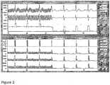
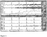
- the results and apparatus disclosed hereinprovide correct triggering on the leading edge of the R wave during periods of normal ECG signals and wide ECG signals, as well as during periods of 60 Hz noise from electrical apparatus and during electromyographic (EMG) noise from skeletal muscles.
- Figure 1shows R wave triggering during different ECG morphologies. The wide ECG shapes shown on the right hand side of the figure can occur during premature ventricular contraction.
- Figure 2illustrates how the threshold for R wave triggering quickly adapts to changes in the noise level on the ECG signal.
- Figures 3 and 4show correct R wave triggering during periods where the ECG signal is contaminated with 60 Hz noise such as occurs from pickup from electrical apparatus.
- Figure 5shows that the threshold for R wave triggering actively adapts to electromyographic (EMG) noise from skeletal muscle by increasing the threshold level to prevent the occurrence of a false trigger.
- EMGelectromyographic
- the adaptive trigger threshold of the present inventionallows a lower initial threshold to be utilized to allow better detection of wide or slow R waves while not increasing the false trigger rate.
- Noise immunityis also improved because noise and artifacts tend to be bipolar or random, while the R wave trigger described herein is based on unipolar trigger recognition.
- the present inventiondoes not require convention signal filtering, which causes signal delays, to reliably trigger on the ECG. This is especially beneficial in times of an arrhythmia when rapid and accurate triggering of the IABP from the ECG is important.
Landscapes
- Health & Medical Sciences (AREA)
- Cardiology (AREA)
- Heart & Thoracic Surgery (AREA)
- Engineering & Computer Science (AREA)
- Life Sciences & Earth Sciences (AREA)
- Public Health (AREA)
- Animal Behavior & Ethology (AREA)
- Biomedical Technology (AREA)
- Veterinary Medicine (AREA)
- General Health & Medical Sciences (AREA)
- Mechanical Engineering (AREA)
- Anesthesiology (AREA)
- Hematology (AREA)
- Biophysics (AREA)
- Medical Informatics (AREA)
- Vascular Medicine (AREA)
- Physiology (AREA)
- Radiology & Medical Imaging (AREA)
- Nuclear Medicine, Radiotherapy & Molecular Imaging (AREA)
- Transplantation (AREA)
- Physics & Mathematics (AREA)
- Pathology (AREA)
- Molecular Biology (AREA)
- Surgery (AREA)
- Measurement And Recording Of Electrical Phenomena And Electrical Characteristics Of The Living Body (AREA)
- Electrotherapy Devices (AREA)
- External Artificial Organs (AREA)
Description
- The present invention is directed to methods and apparatus for generating a trigger from the R wave of an electrocardiogram (ECG) waveform using a threshold that adapts to changes in slope of the leading edge of the R wave. The invention can be used, for example, to trigger an intra-aortic balloon pump (IABP) to control an intra-aortic balloon (IAB), to trigger an interactive cardiac device such as a cardiac stimulator or defibrillator, and as an ECG monitor.
- Throughout this application various publications are referred to in parenthesis. Full citations for these references may be found at the end of the specification immediately preceding the claims.
- Subjects with poorly functioning hearts can have compromised blood supply to vital organs. The pumping action of the heart and the systemic blood supply can be improved by the use of an intra-aortic balloon pump (IABP) to control an intraaortic balloon (IAB). IABPs are used in cardiology patients and cardiac surgery patients (Baskett et al., 2002; Mehlhorn et al., 1999).
- In each cardiac cycle, the IAB is inflated by means of the pumping device after the end of the ejection phase of the left ventricle of the heart, and is deflated again before the commencement of the following ejection phase. It has been suggested that systemic hemodynamics and myocardial efficiency can be improved by balloon deflation approaching or simultaneous with left ventricular ejection (Kern et al., 1999). For optimal functioning of the IABP, it is important that the IAB be inflated and deflated at the correct times in the cardiac cycle.
- Methods and apparatus for controlling the inflation of an IAB have been described, for example, in
Sakamoto et al., 1995; U.S. Patent Nos. 4,692,148 ,6,258,035 ,6,569,103 and6,887,206 ; andU.S. Patent Application Publication Nos. 20040059183 and20050148812 . - Deflation of the IAB can be triggered using the electrocardiogram (ECG) of the subject's heart (e.g.,
Ohley et al., 2002; U.S. Patent Nos. 4,692,148 ,4,809,681 ,6,290,641 and6,679,829 ). Methods and apparatus for determining a trigger signal from an ECG have been described (e.g.,U.S. Patent Nos. 4,571,547 and5,355,891 ). Typically, the timing of deflation of the IAB is based on the R Wave of the ECG. There is a need for accurate R wave triggering where the trigger adapts in real time to changes in R wave amplitude and rise time during the leading phase of the R wave. - The present invention satisfies this need by providing improved methods and apparatus for generating a trigger from the R wave of an electrocardiogram (ECG) waveform using a threshold that adapts to the slope of the R wave while still within the leading edge of the R wave.
- The method comprises the steps according to the subject-matter of
claim 1. - The apparatus of the present invention comprises a processing unit according to the subject-matter of claim 2.
- The present invention advances the state of R wave triggering by providing real time triggering during the leading edge of the R wave with improved trigger recognition and reduced false triggers and missed triggers.
- Additional objects of the invention will be apparent from the description which follows.
Figure 1 . R wave triggering during different ECG morphologies. Top panels inFigures 1-5 show, from top to bottom, simulated ECG, slope of ECG over 4 ms periods, and length filter or adaptive threshold for the R wave trigger. Bottom panels show, from top to bottom, occurrence of trigger, and ECG height over periods of 32 ms, 24 ms and 16 ms. The figure illustrates that the adaptive threshold can adjust the threshold for the R wave trigger during changes in R wave shape or morphology. The time scale on the X-axis ofFigures 1-5 is in seconds.Figure 2 . R wave triggering during changes in noise level. The figure illustrates how the threshold for R wave triggering quickly adapts to changes in the noise level on the ECG signal. The time period over which the ECG height is checked (bottom panel) prevents signal frequencies higher than expected for the R wave from meeting the trigger criteria.Figure 3 . R wave triggering during introduction of 60 cycle noise on ECG. The threshold actively adapts to the 60 cycle noise by increasing the threshold level during real time. The time period over which the ECG height is checked prevents frequencies outside of the range of the R wave from generating a trigger.Figure 4 . R wave triggering during modulated 60 cycle noise on ECG. The threshold rapidly adapts to changes in the amplitude of the 60 cycle noise.Figure 5 . R wave triggering during skeletal muscle noise on the ECG. The threshold actively adapts to electromyographic (EMG) noise from skeletal muscles by increasing the threshold level to prevent the occurrence of a false trigger.- The present invention is directed to methods and apparatus for generating a trigger from an R wave of an electrocardiogram (ECG) waveform using a threshold that adapts to the slope of the R wave while still within the leading edge of the R wave. The invention can be used in subjects with a normal cardiac rhythm. However, the invention is particularly useful in subjects who have cardiac arrhythmia because it allows earlier R wave recognition, during the leading edge of the R wave. The earlier an R wave is recognized during cardiac arrhythmia, the more time that is available to deflate an IAB before the next cardiac cycle. The invention may be used in the treatment of human subjects or in veterinary medicine.
- The method of the present invention comprises the following steps a)-f). Step a) involves normalizing the amplitude of the expected R wave based on preceding R waves recorded from the same subject. Step b) involves setting a minimum threshold for the trigger, where the minimum threshold is a percentage of the amplitude of the expected R wave. The R wave may represent an increase or a decrease in voltage from the ECG baseline depending on the polarity of the ECG signal that is recorded. Thus, the leading edge of the R wave may represent either a rise or fall from the baseline of the ECG. The amplitude of the expected R wave is typically normalized based on preceding R waves recorded from the same subject. More recently occurring R waves can be weighted more heavily in determining the amplitude of the expected R wave than less recently occurring R waves. The minimum threshold criteria is important to prevent falsely triggering on small amplitude artifacts or noise. The minimum threshold can be set, for example, at about 1/3 to about ½ of the amplitude of the expected R wave. Preferably, the minimum threshold is set at 1/3 of the amplitude of the expected R wave. The adaptive trigger threshold feature of the present invention allows a lower initial minimum threshold to be used to allow better detection of R waves with a slowly changing leading edge, while not increasing the false trigger rate.
- Step c) involves measuring slopes of the R wave over successive small time periods during the leading edge of the R wave, where slopes corresponding to waveforms that consist of frequencies greater than the expected R wave prevent generation of a trigger. The individual time periods may be, for example, 1 msec to 5 msec in duration. Preferably, individual time periods are at least 4 msec in duration. The total duration of the successive time periods may be, for example, 16 - 40 msec. This step can involve using a weighted average of the observed slope, with the most recent values getting the most weight and successively less weight applied as the values gets older. This is a dynamic measurement and adjustment that solely relies on the values seen within the existing R wave and not on previous R waves. Preferably, slopes corresponding to waveforms that consist of frequencies greater than or equal to 30-40 Hz are excluded from generating a trigger. The method can further comprise excluding slopes corresponding to waveforms that consist of frequencies less than or equal to 5-10 Hz from generating a trigger.
- Step d) involves adjusting the threshold for the trigger for the R wave during the leading edge of the R wave, where the minimum threshold is increased if the slopes measured in c) are greater than expected for the R wave. Preferably, the adjusted threshold is not allowed to exceed a maximum percentage of the amplitude of the expected R wave. More preferably, the adjusted threshold is not allowed to exceed 2/3rd of the amplitude of the expected R wave. The minimum threshold criterion set in step b) is critical in that it allows time to sample several small increments of the leading edge of the R wave in order to adjust the threshold value before the minimum threshold value is exceeded.
- Step e) involves applying a scalar value to the slopes measured in c) to set a frequency above which signal frequencies are not considered valid for recognition as an R wave. This feature further improves the recognition of the R wave. The scalar value can be applied using various mathematical operations. A preferred method comprises multiplying the slopes obtained in step c) by a frequency scalar value that determines the frequencies that are allowed to generate a trigger in step f). This will eliminate triggers based on frequencies greater than what the chosen scalar will allow, as illustrated in Table 1.
Table 1. Effects of frequency scalar on rejection of frequencies for ECG trigger detection. Frequencies in Hz. Frequency Scalar 2 2.5 3 3.5 4 5 6 Frequencies ≥ that are rejected 70 48 40 32 28 22 18 - Step f) involves generating a trigger within the leading edge of the R wave when the amplitude of the R wave reaches the threshold. The generated trigger may be used to trigger an intra-aortic balloon pump (IABP). In particular, the trigger may be used to trigger deflation of an intra-aortic balloon (IAB) by an intra-aortic balloon pump (IABP). In addition, the generated trigger can be used to trigger an interactive cardiac device such as a cardiac stimulator or defibrillator, and as an ECG monitor.
- The invention also provides apparatus for generating a trigger from an R wave of an electrocardiogram (ECG) waveform using a threshold that adapts to the slope of the R wave while still within the leading edge of the R wave, where the apparatus comprises a processing unit for:
- a) normalizing the amplitude of the expected R wave based on preceding R waves recorded from the same subject;
- b) setting a minimum threshold for the trigger, where the minimum threshold is a percentage of the amplitude of the expected R wave;
- c) measuring slopes of the R wave over successive small time periods during the leading edge of the R wave, where slopes corresponding to waveforms that consist of frequencies greater than the expected R wave prevent generation of a trigger;
- d) adjusting the threshold for the trigger for the R wave during the leading edge of the R wave, where the minimum threshold is increased if the slopes measured in c) are greater than expected for the R wave;
- e) applying a scalar value to the slopes measured in c) to set a frequency above which signal frequencies are not considered valid for recognition as an R wave; and
- f) generating a trigger within the leading edge of the R wave when the amplitude of the R wave reaches the threshold.
- Preferably, the apparatus also includes inputs from the subject's electrocardiogram (ECG) and from the subject's arterial pressure (AP), and a processing unit for detecting cardiac arrhythmia in the subject from the subject's electrocardiogram (ECG) and/or from the subject's arterial pressure. Preferably, the apparatus also includes an output that triggers an IABP, in particular deflation of the IAB. The apparatus can be incorporated in an intra-aortic balloon pump console system. The apparatus can include an output that triggers an interactive cardiac device such as a cardiac stimulator or defibrillator, and/or an output to an ECG monitor.
- The method or processing unit can further comprise requiring that a minimum number of changes in amplitude of the R wave measured over successive time periods in step c) are in the same direction of change in order to generate a trigger. Requiring a minimum number of segments moving in the same direction helps to rule out a trigger on frequencies higher than the expected R wave. This check is done starting with the first time period of the leading edge of the R wave to pre-validate the trigger so as not to impose any delay in issuing the trigger once the amplitude criteria are satisfied.
- The method or processing unit can further comprise requiring that a change in amplitude of the R wave measured over an individual time period in step c) has a minimum change with respect to the change in amplitude measured for the preceding time period in order for a trigger to be generated.
- The method or processing unit can further comprise increasing the threshold for the trigger in the presence of ECG signals having a frequency component in the higher range expected for the R wave. The ECG normally has a frequency range of about 10 to 30 Hz. The threshold for the trigger can be increased, for example, in the presence of ECG signals having a 25-30 Hz frequency component. For example, the threshold for the trigger of an R wave can be increased in the presence of signals that are consistent with frequencies of an R wave such that noise that is less than 2/3rd of the threshold is excluded from being falsely called an R wave, but the true R wave is still recognized if and when it exceeds the threshold. This can be achieved by setting the frequency scalar multiplier to a value such that it is within the upper range of expected R wave.
- Another refinement is to have the ECG waveform normalized in amplitude, such that the amplitude of the ECG is gained to achieve a target value. This allows for a fixed set of thresholds for triggering and filter coefficients that would not have to be scaled for the strength of the signal received.
- The time period during which the threshold is checked for a trigger can be specified. For example, the time period can be a limited time period, for example a time period of 16 to 40 ms. The threshold for the trigger can also be checked looking back, for example, at 16, 20, 24, 28, 32 and 40 ms intervals. These specified time intervals help define the frequencies that are allowed to generate a trigger.
- The method or processing unit further provides that after a trigger is generated in step f) , a second trigger cannot be generated within a specified time period. This time period may be set, for example, at around 280 ms.
- The present invention is illustrated in the following Experimental Details section, which is set forth to aid in the understanding of the invention, and should not be construed to limit in any way the scope of the invention as defined in the claims that follow thereafter.
- A problem existed in recognizing the various morphologies that can occur for the QRS segment of an ECG. The goal is to reliably trigger on the leading edge of the R wave in real time. The ECG normally has a frequency range of 10 to 30 Hz. The R wave of the ECG can have slopes and rise times that differ by a factor of 5 or more. The leading edge of the R wave can have a rise time from 16 msec to 100 msec. Trigger thresholds set to detect the slowest R waves may also end up detecting ECG T waves and P waves in the faster ECG morphologies. Thus, there is the need to have an adaptive trigger threshold that adjusts in real time for differing ECG morphologies.
- One purpose of the present invention is to prevent triggering on a signal that has frequencies above the normal range that would otherwise have sufficient slope and amplitude to be considered the leading edge of the R wave. A further purpose of the invention is based on the need to recognize the leading edge of the ECG R wave as soon as possible, so that the IABP can determine when the next cardiac cycle is taking place. This requirement does not allow for traditional filtering techniques that cause a significant propagation delay in the signal and result in late recognition of the start of the R wave.
- The present invention was incorporated into a currently used IABP device (Arrow International AUTOCAT® version 2.22). In testing against a subset of the American Heart Association (AHA) ECG database (42 tapes), the following improvements in R wave triggering were obtained with the present invention compared to the version of the IABP without the present invention. The percentage of missed triggers was reduced 40% and the percentage of false triggers was reduced 90%. Thus, the present invention provides better detection of a wide range of R waves while at the same time reducing the incidence of false detection.
- As shown in
Figures 1-5 , the results and apparatus disclosed herein provide correct triggering on the leading edge of the R wave during periods of normal ECG signals and wide ECG signals, as well as during periods of 60 Hz noise from electrical apparatus and during electromyographic (EMG) noise from skeletal muscles.Figure 1 shows R wave triggering during different ECG morphologies. The wide ECG shapes shown on the right hand side of the figure can occur during premature ventricular contraction.Figure 2 illustrates how the threshold for R wave triggering quickly adapts to changes in the noise level on the ECG signal.Figures 3 and4 show correct R wave triggering during periods where the ECG signal is contaminated with 60 Hz noise such as occurs from pickup from electrical apparatus.Figure 5 shows that the threshold for R wave triggering actively adapts to electromyographic (EMG) noise from skeletal muscle by increasing the threshold level to prevent the occurrence of a false trigger. - Use of the adaptive trigger threshold of the present invention allows a lower initial threshold to be utilized to allow better detection of wide or slow R waves while not increasing the false trigger rate. Noise immunity is also improved because noise and artifacts tend to be bipolar or random, while the R wave trigger described herein is based on unipolar trigger recognition. The present invention does not require convention signal filtering, which causes signal delays, to reliably trigger on the ECG. This is especially beneficial in times of an arrhythmia when rapid and accurate triggering of the IABP from the ECG is important.
- Baskett RJ, Ghali WA, Maitland A, Hirsch GM. The intraaortic balloon pump in cardiac surgery. Ann. Thorac. Surg. 74(4):1276-87, 2002.
- Kern, M, Aguirre, F, Caracciolo, E, Bach, R, Donohue, T, Lasorda, D, Ohman, M, Schnitzler, R, King, D, Ohley, W, Grayzel, J. Hemodynamic effects of new intra-aortic balloon counterpulsation timing method in patients: A multicenter evaluation. American Heart Journal 137:1129-6, 1999.
- Mehlhorn U, Kroner A, de Vivie ER. 30 years clinical intra-aortic balloon pumping: facts and figures. Thorac. Cardiovasc. Surg. 47 Suppl 2:298-303, 1999.
- Ohley, WJ, Nigroni, P, Williams, J, Sarras, L, Hamilton, R. Intraaortic balloon pump response to arrhythmias: Development and implementation of algorithms. Cardioangiology 51(5): 483-7, 2002.
- Sakamoto, T, Arai, H, Toshiyuki, M, Suzuki, A. A new algorithm of intra aortic balloon pumping in patients with atrial fibrillation. ASAIO Journal 41:79-83, 1995.
U.S. Patent No. 4,571,547, Adaptive signal detection system especially for physiological signals such as the R waves of ECG signals, which is desensitized to artifacts, Day, issued February 18, 1986 .U.S. Patent No. 4,692,148, Intra-aortic balloon pump apparatus and method of using same, Kantrowitz et al., issued September 8, 1987 .U.S. Patent No. 4,809,681, Electrocardiographic measurement method for controlling an intra-aortic balloon pump, Kantrowitz et al., issued March 7, 1989 .U.S. Patent No. 5,355,891, ECG analyzer, Wateridge et al., issued October 18, 1994 .U.S. Patent No. 6,258,035, Device for determining a characteristic point in the cardiac cycle, Hoeksel et al., issued July 10, 2001 .U.S. Patent No. 6,290,641, Intra-aortic balloon pump having improved automated electrocardiogram based intra-aortic balloon deflation timing, Nigroni et al., issued September 18, 2001 .U.S. Patent No. 6,569,103, Device for determining a characteristic point in the cardiac cycle, Hoeksel et al., issued May 27, 2003 .U.S. Patent No. 6,679,829, Intra-aortic balloon pump having improved automated electrocardiogram based intra-aortic balloon deflation timing, Nigroni et al., issued January 20, 2004 .U.S. Patent No. 6,887,206, Device for determining a characteristic point in the cardiac cycle, Hoeksel et al., issued May 3, 2005 .U.S. Patent Application Publication No. 2004/0059183, Apparatus for controlling heart assist devices, Jansen et al., published March 25, 2004 .U.S. Patent Application Publication No. 2005/0148812, Timing of intra-aortic balloon pump therapy, Nigroni et al., published July 7, 2005 .
Claims (16)
- A method of generating a trigger from an R wave of an electrocardiogram (ECG) waveform using a threshold that adapts to the slope of the R wave while still within the leading edge of the R wave, the method comprising:a) normalizing the amplitude of the expected R wave based on preceding R waves recorded from the same subject;b) setting a minimum threshold for the trigger, where the minimum threshold is a percentage of the amplitude of the expected R wave;c) measuring slopes of the R wave over successive small time periods during the leading edge of the R wave, where slopes corresponding to waveforms that consist of frequencies greater than or equal to the expected R wave are prevented from generating a trigger;d) adjusting the threshold for the trigger for the R wave during the leading edge of the R wave, where the minimum threshold is increased if the slopes measured in c) are greater than expected for the R wave;e) applying a scalar value to the slopes measured in c) to set a frequency above which signal frequencies are not considered valid for recognition as an R wave; andf) generating a trigger within the leading edge of the R wave when the amplitude of the R wave reaches the threshold.
- An apparatus for generating a trigger from an R wave of an electrocardiogram (ECG) waveform using a threshold that adapts to the slope of the R wave while still within the leading edge of the R wave, the apparatus comprising a processing unit for executing the following steps:a) normalizing the amplitude of the expected R wave based on preceding R waves recorded from the same subject;b) setting a minimum threshold for the trigger, where the minimum threshold is a percentage of the amplitude of the expected R wave;c) measuring slopes of the R wave over successive small time periods during the leading edge of the R wave, where slopes corresponding to waveforms that consist of frequencies greater than or equal to the expected R wave are prevented from generating a trigger;d) adjusting the threshold for the trigger for the R wave during the leading edge of the R wave, where the minimum threshold is increased if the slopes measured in c) are greater than expected for the R wave;e) applying a scalar value to the slopes measured in c) to set a frequency above which signal frequencies are not considered valid for recognition as an R wave; andf) generating a trigger within the leading edge of the R wave when the amplitude of the R wave reaches the threshold.
- The apparatus of Claim 2, wherein the apparatus comprises an input from the electrocardiogram (ECG) of a subject and/or an input from the subject's arterial pressure, for example where the apparatus comprises a processing unit for detecting cardiac arrhythmia from a subject's electrocardiogram (ECG) and/or from a subject's arterial pressure.
- The method of Claim 1 or the apparatus of Claim 2 or 3, wherein, when the amplitude of the expected R wave is normalized based on preceding R waves in the ECG, more recently occurring R waves are weighted more heavily in determining the amplitude of the expected R wave than less recently occurring R waves.
- The method of Claim 1 or 4 or the apparatus of any of Claims 2-4, wherein the minimum threshold in step b) is set at 1/3rd of the amplitude of the expected R wave or at ½ of the amplitude of the expected R wave.
- The method of any of Claims 1, 4 or 5 or the apparatus of any of Claims 2-5, wherein individual time periods in step c) are 1 msec to 5 msec in duration or at least 4 msec in duration.
- The method of any of Claims 1 or 5-6 or the apparatus of any of Claims 2-6, wherein the successive time periods in step c) have a total duration of 16 - 40 msec.
- The method of any of Claims 1 or 5-7 or the apparatus of any of Claims 2-7, wherein slopes corresponding to waveforms that predominately have frequencies greater than or equal to 40 Hz are excluded from generating a trigger or wherein slopes corresponding to waveforms that predominately have frequencies greater than or equal to 30 Hz are excluded from generating a trigger.
- The method of any of Claims 1 or 5-8 or the apparatus of any of Claims 2-8, wherein the adjusted threshold is not allowed to exceed a maximum percentage of the amplitude of the expected R wave or wherein the adjusted threshold is not allowed to exceed 2/3rd of the amplitude of the expected R wave.
- The method of any of Claims 1 or 5-9 or the apparatus of any of Claims 2-9, which further comprises excluding slopes corresponding to waveforms that predominately have frequencies less than or equal to 5 Hz or 10 Hz from generating a trigger.
- The method of any of Claims 1 or 5-10 or the apparatus of any of Claims 2-10, which further comprises requiring that a minimum number of changes in amplitude of the R wave measured over successive time periods in step c) are in the same direction of change in order to generate a trigger.
- The method of any of Claims 1 or 5-11 or the apparatus of any of Claims 2-11, which further comprises requiring that a change in amplitude of the R wave measured over a time period in step c) has a minimum change with respect to the change in amplitude measured over the preceding time period in order to generate a trigger.
- The method of any of Claims 1 or 5-12 or the apparatus of any of Claims 2-12, which further comprises increasing the threshold for the trigger in the presence of ECG signals having a frequency component in the higher range expected for the R wave.
- The method of any of Claims 1 or 5-13, wherein the trigger generated in step f) is appropriate to trigger an intra-aortic balloon pump (IABP), or the apparatus of any of Claims 2-13 wherein the apparatus comprises an output that triggers an intra-aortic balloon pump (IABP), in particular where the trigger triggers deflation of an intra-aortic balloon (IAB) by an intra-aortic balloon pump (IABP).
- The method of any of Claims 1 or 5-13, wherein the trigger generated in step f) is appropriate to trigger a cardiac device, in particular where the cardiac device is a cardiac stimulator, a defibrillator, or an ECG monitor.
- The apparatus of any of Claims 2-13, wherein the apparatus is incorporated in an intra-aortic balloon pump console system.
Applications Claiming Priority (2)
| Application Number | Priority Date | Filing Date | Title |
|---|---|---|---|
| US75896206P | 2006-01-12 | 2006-01-12 | |
| PCT/US2006/046441WO2007087014A2 (en) | 2006-01-12 | 2006-12-06 | Adaptive real time ecg triggering and uses thereof |
Publications (3)
| Publication Number | Publication Date |
|---|---|
| EP1971259A2 EP1971259A2 (en) | 2008-09-24 |
| EP1971259A4 EP1971259A4 (en) | 2010-01-06 |
| EP1971259B1true EP1971259B1 (en) | 2017-02-15 |
Family
ID=38309696
Family Applications (1)
| Application Number | Title | Priority Date | Filing Date |
|---|---|---|---|
| EP06844852.1AActiveEP1971259B1 (en) | 2006-01-12 | 2006-12-06 | Adaptive real time ecg triggering and uses thereof |
Country Status (5)
| Country | Link |
|---|---|
| US (1) | US8204582B2 (en) |
| EP (1) | EP1971259B1 (en) |
| JP (1) | JP5372521B2 (en) |
| CA (1) | CA2635746C (en) |
| WO (1) | WO2007087014A2 (en) |
Families Citing this family (60)
| Publication number | Priority date | Publication date | Assignee | Title |
|---|---|---|---|---|
| US8078274B2 (en) | 2003-02-21 | 2011-12-13 | Dtherapeutics, Llc | Device, system and method for measuring cross-sectional areas in luminal organs |
| US10413211B2 (en) | 2003-02-21 | 2019-09-17 | 3Dt Holdings, Llc | Systems, devices, and methods for mapping organ profiles |
| US10172538B2 (en) | 2003-02-21 | 2019-01-08 | 3Dt Holdings, Llc | Body lumen junction localization |
| US7818053B2 (en) | 2003-02-21 | 2010-10-19 | Dtherapeutics, Llc | Devices, systems and methods for plaque type determination |
| US8784336B2 (en) | 2005-08-24 | 2014-07-22 | C. R. Bard, Inc. | Stylet apparatuses and methods of manufacture |
| US8388546B2 (en) | 2006-10-23 | 2013-03-05 | Bard Access Systems, Inc. | Method of locating the tip of a central venous catheter |
| US7794407B2 (en) | 2006-10-23 | 2010-09-14 | Bard Access Systems, Inc. | Method of locating the tip of a central venous catheter |
| US9649048B2 (en) | 2007-11-26 | 2017-05-16 | C. R. Bard, Inc. | Systems and methods for breaching a sterile field for intravascular placement of a catheter |
| US9636031B2 (en) | 2007-11-26 | 2017-05-02 | C.R. Bard, Inc. | Stylets for use with apparatus for intravascular placement of a catheter |
| US9521961B2 (en) | 2007-11-26 | 2016-12-20 | C. R. Bard, Inc. | Systems and methods for guiding a medical instrument |
| US10524691B2 (en) | 2007-11-26 | 2020-01-07 | C. R. Bard, Inc. | Needle assembly including an aligned magnetic element |
| US8781555B2 (en) | 2007-11-26 | 2014-07-15 | C. R. Bard, Inc. | System for placement of a catheter including a signal-generating stylet |
| US10449330B2 (en) | 2007-11-26 | 2019-10-22 | C. R. Bard, Inc. | Magnetic element-equipped needle assemblies |
| US10751509B2 (en) | 2007-11-26 | 2020-08-25 | C. R. Bard, Inc. | Iconic representations for guidance of an indwelling medical device |
| US8849382B2 (en) | 2007-11-26 | 2014-09-30 | C. R. Bard, Inc. | Apparatus and display methods relating to intravascular placement of a catheter |
| ES2465915T3 (en) | 2007-11-26 | 2014-06-09 | C.R. Bard, Inc. | Integrated system for intravascular catheter placement |
| US8676540B1 (en) | 2007-12-11 | 2014-03-18 | Sandia Corporation | Methods for automatic trigger threshold adjustment |
| US9901714B2 (en) | 2008-08-22 | 2018-02-27 | C. R. Bard, Inc. | Catheter assembly including ECG sensor and magnetic assemblies |
| US8437833B2 (en) | 2008-10-07 | 2013-05-07 | Bard Access Systems, Inc. | Percutaneous magnetic gastrostomy |
| JP5795576B2 (en) | 2009-06-12 | 2015-10-14 | バード・アクセス・システムズ,インコーポレーテッド | Method of operating a computer-based medical device that uses an electrocardiogram (ECG) signal to position an intravascular device in or near the heart |
| US9532724B2 (en) | 2009-06-12 | 2017-01-03 | Bard Access Systems, Inc. | Apparatus and method for catheter navigation using endovascular energy mapping |
| EP2464407A4 (en) | 2009-08-10 | 2014-04-02 | Bard Access Systems Inc | Devices and methods for endovascular electrography |
| WO2011097312A1 (en) | 2010-02-02 | 2011-08-11 | C.R. Bard, Inc. | Apparatus and method for catheter navigation and tip location |
| EP4122385A1 (en) | 2010-05-28 | 2023-01-25 | C. R. Bard, Inc. | Insertion guidance system for needles and medical components |
| EP2912999B1 (en) | 2010-05-28 | 2022-06-29 | C. R. Bard, Inc. | Apparatus for use with needle insertion guidance system |
| BR112013002431B1 (en) | 2010-08-20 | 2021-06-29 | C.R. Bard, Inc | SYSTEM FOR RECONFIRMING THE POSITION OF A CATHETER INSIDE A PATIENT |
| US8801693B2 (en) | 2010-10-29 | 2014-08-12 | C. R. Bard, Inc. | Bioimpedance-assisted placement of a medical device |
| RU2609203C2 (en) | 2011-07-06 | 2017-01-30 | Си.Ар. Бард, Инк. | Determination and calibration of needle length for needle guidance system |
| US8849388B2 (en) | 2011-09-08 | 2014-09-30 | Apn Health, Llc | R-wave detection method |
| JP2015516846A (en) | 2012-04-05 | 2015-06-18 | バード・アクセス・システムズ,インコーポレーテッド | Device and system for navigating and positioning a central venous catheter within a patient |
| US11759268B2 (en) | 2012-04-05 | 2023-09-19 | C. R. Bard, Inc. | Apparatus and methods relating to intravascular positioning of distal end of catheter |
| US10159531B2 (en) | 2012-04-05 | 2018-12-25 | C. R. Bard, Inc. | Apparatus and methods relating to intravascular positioning of distal end of catheter |
| CN103006208B (en)* | 2012-12-29 | 2014-05-28 | 重庆邮电大学 | Method and device for calibrating R wave of electrocardiosignal |
| US8812091B1 (en) | 2013-03-15 | 2014-08-19 | Apn Health, Llc | Multi-channel cardiac measurements |
| US8788024B1 (en) | 2013-03-15 | 2014-07-22 | Apn Health, Llc | Multi-channel cardiac measurements |
| US9814816B2 (en) | 2013-06-21 | 2017-11-14 | Corvivo, Inc. | Artificial ventricles |
| US9320841B2 (en)* | 2013-06-21 | 2016-04-26 | Corvivo, Inc. | Ventricular assist device |
| US9326793B2 (en)* | 2013-07-16 | 2016-05-03 | Fawaz ALHUMAID | Needle for physically separating and penetrating the pericardium |
| US9078575B2 (en) | 2013-10-30 | 2015-07-14 | Apn Health, Llc | Heartbeat categorization |
| US9078572B2 (en) | 2013-10-30 | 2015-07-14 | Apn Health, Llc | Heartbeat detection and categorization |
| WO2015120256A2 (en) | 2014-02-06 | 2015-08-13 | C.R. Bard, Inc. | Systems and methods for guidance and placement of an intravascular device |
| US9517102B2 (en)* | 2014-03-25 | 2016-12-13 | Fawaz ALHUMAID | Cautery needle for separating and/or penetrating the pericardium |
| US9314179B1 (en) | 2014-09-25 | 2016-04-19 | Apn Health, Llc | Time transformation of local activation times |
| US10973584B2 (en) | 2015-01-19 | 2021-04-13 | Bard Access Systems, Inc. | Device and method for vascular access |
| US10271795B2 (en) | 2015-06-12 | 2019-04-30 | C. R. Bard, Inc. | Systems and methods for confirmation of prior catheter tip placement |
| WO2016210325A1 (en) | 2015-06-26 | 2016-12-29 | C.R. Bard, Inc. | Connector interface for ecg-based catheter positioning system |
| WO2017061386A1 (en)* | 2015-10-07 | 2017-04-13 | 学校法人 久留米大学 | Heartbeat-synchronous type blood circulation support system and control method, and heartbeat-synchronous type electrical stimulation device |
| CN105411579B (en)* | 2015-12-28 | 2018-06-08 | 中科院微电子研究所昆山分所 | A kind of electrocardiogram R wave detection method and device |
| JP6603584B2 (en)* | 2016-01-14 | 2019-11-06 | 株式会社クロスウェル | Periodic wave detection device, periodic wave detection method and program |
| US11000207B2 (en) | 2016-01-29 | 2021-05-11 | C. R. Bard, Inc. | Multiple coil system for tracking a medical device |
| US10357168B2 (en) | 2016-03-07 | 2019-07-23 | Apn Health, Llc | Time transformation of local activation times |
| JP6632511B2 (en)* | 2016-11-04 | 2020-01-22 | 日本ライフライン株式会社 | Intracardiac defibrillation catheter system |
| CN107361764B (en)* | 2017-06-16 | 2020-05-22 | 华南理工大学 | A Rapid Extraction Method of ECG Signal Characteristic Waveform R Wave |
| WO2019236664A1 (en)* | 2018-06-06 | 2019-12-12 | Zoll Medical Corporation | Systems and methods of synchronizing chest compressions with myocardial activity |
| US10992079B2 (en) | 2018-10-16 | 2021-04-27 | Bard Access Systems, Inc. | Safety-equipped connection systems and methods thereof for establishing electrical connections |
| US11285313B2 (en) | 2019-05-02 | 2022-03-29 | Nupulsecv, Inc. | Predictive QRS detection and R-to-R timing systems and methods |
| US20200345911A1 (en)* | 2019-05-02 | 2020-11-05 | Nupulsecv, Inc. | Predictive qrs detection and r-to-r timing systems and methods |
| DE102020004697A1 (en)* | 2020-08-03 | 2022-02-03 | Hochschule Offenburg | Control for extracorporeal circulatory support |
| DE102021005828A1 (en)* | 2021-11-24 | 2023-05-25 | Hochschule für Technik, Wirtschaft und Medien Offenburg | Apparatus and method for monitoring and optimizing temporal trigger stability |
| US20250018170A1 (en)* | 2023-07-14 | 2025-01-16 | Nupulsecv, Inc. | Real-time detection of r-waves and methods therefor |
Family Cites Families (16)
| Publication number | Priority date | Publication date | Assignee | Title |
|---|---|---|---|---|
| US139605A (en) | 1873-06-03 | Improvement in gas-retorts | ||
| US4571547A (en) | 1983-06-27 | 1986-02-18 | Clinical Data Inc. | Adaptive signal detection system especially for physiological signals such as the R waves of ECG signals, which is desensitized to artifacts |
| US4617938A (en)* | 1984-12-26 | 1986-10-21 | Yair Shimoni | Method and system for distinguishing R-wave electrocardiograph signals for synchronizing purposes |
| US4692148A (en)* | 1986-03-28 | 1987-09-08 | Aisin Seiki Kabushiki Kaisha | Intra-aortic balloon pump apparatus and method of using same |
| US4809681A (en) | 1986-03-28 | 1989-03-07 | Aisin Seiki Kabushiki Kaisha | Electrocardiographic measurement method for controlling an intra-aortic balloon pump |
| GB9200586D0 (en) | 1992-01-13 | 1992-03-11 | Oxford Medical Ltd | Ecg analyzer |
| US5365932A (en)* | 1993-09-02 | 1994-11-22 | Telectronics Pacing System, Inc. | Cardiac signal sensing device having sensitivity automatically controlled in response to metabolic demand |
| NL1001979C1 (en) | 1995-12-22 | 1997-06-24 | Cardiovasculair Research Insti | Device for determining a characteristic point in the heart cycle. |
| US6569103B2 (en)* | 1995-12-22 | 2003-05-27 | Arrow International Investment Corp. | Device for determining a characteristic point in the cardiac cycle |
| US5913814A (en) | 1997-08-26 | 1999-06-22 | Belmont Instrument Corporation | Method and apparatus for deflation of an intra-aortic balloon |
| US6070097A (en)* | 1998-12-30 | 2000-05-30 | General Electric Company | Method for generating a gating signal for cardiac MRI |
| US6290641B1 (en)* | 1999-05-20 | 2001-09-18 | Datascope Investment Corp. | Intra-aortic balloon pump having improved automated electrocardiogram based intra-aortic balloon deflation timing |
| NL1016320C2 (en) | 2000-10-03 | 2002-04-04 | Jozef Reinier Cornelis Jansen | Device for controlling heart supporting devices. |
| US7139605B2 (en)* | 2003-03-18 | 2006-11-21 | Massachusetts Institute Of Technology | Heart rate monitor |
| US7250025B2 (en)* | 2003-08-29 | 2007-07-31 | Datascope Investment Corp. | Timing of intra-aortic balloon pump therapy |
| US7283870B2 (en)* | 2005-07-21 | 2007-10-16 | The General Electric Company | Apparatus and method for obtaining cardiac data |
- 2006
- 2006-12-06CACA2635746Apatent/CA2635746C/enactiveActive
- 2006-12-06EPEP06844852.1Apatent/EP1971259B1/enactiveActive
- 2006-12-06WOPCT/US2006/046441patent/WO2007087014A2/enactiveApplication Filing
- 2006-12-06JPJP2008550312Apatent/JP5372521B2/enactiveActive
- 2006-12-06USUS11/634,687patent/US8204582B2/enactiveActive
Non-Patent Citations (1)
| Title |
|---|
| None* |
Also Published As
| Publication number | Publication date |
|---|---|
| EP1971259A2 (en) | 2008-09-24 |
| EP1971259A4 (en) | 2010-01-06 |
| CA2635746C (en) | 2017-01-10 |
| JP5372521B2 (en) | 2013-12-18 |
| WO2007087014A2 (en) | 2007-08-02 |
| US8204582B2 (en) | 2012-06-19 |
| CA2635746A1 (en) | 2007-08-02 |
| WO2007087014A3 (en) | 2008-12-18 |
| JP2009523483A (en) | 2009-06-25 |
| US20070161916A1 (en) | 2007-07-12 |
Similar Documents
| Publication | Publication Date | Title |
|---|---|---|
| EP1971259B1 (en) | Adaptive real time ecg triggering and uses thereof | |
| CN107530021B (en) | Implantable medical device having means for determining whether shockable rhythm classification criteria are met including determining T-wave oversensing | |
| US6440082B1 (en) | Method and apparatus for using heart sounds to determine the presence of a pulse | |
| US5163429A (en) | Hemodynamically responsive system for treating a malfunctioning heart | |
| US9981142B2 (en) | Pulse detection apparatus, software, and methods using patient physiological signals | |
| US5738105A (en) | Method and apparatus for sensing R-waves using both near field and far field sensing simultaneously | |
| JP5457376B2 (en) | Accurate cardiac event detection in implantable cardiac stimulation devices | |
| US5792195A (en) | Acceleration sensed safe upper rate envelope for calculating the hemodynamic upper rate limit for a rate adaptive cardiac rhythm management device | |
| US4984572A (en) | Hemodynamically responsive system for and method of treating a malfunctioning heart | |
| US9950178B2 (en) | Pulse detection method and apparatus using patient impedance | |
| US20020161407A1 (en) | Method for improving cardiac function following delivery of a defibrillation shock | |
| US20080208070A1 (en) | Defibrillator with Automatic Shock First/Cpr First Algorithm | |
| JPH01110345A (en) | Apparatus and method for detecting heart character by electric stimulation | |
| US11541246B2 (en) | Device and method for detecting ventricular fibrillation | |
| EP1968666A2 (en) | Methods and apparatus for selecting intra-aortic balloon deflation timing | |
| US20130046194A1 (en) | Arrhythmia Classification | |
| US8738120B2 (en) | Implantable medical device and method comprising means for detecting and classifying an arrhythmia | |
| EP4353306A1 (en) | Defibrillator for assessing a likelihood of patient refibrillation | |
| HK40057039A (en) | Device and method for detecting ventricular fibrillation | |
| Padala et al. | B-PO03-045 LEFT BUNDLE BRANCH AREA PACING IN PATIENTS WITH AV NODAL AND INFRA NODAL DISEASE: A MULTICENTER PROSPECTIVE STUDY | |
| CN113229780A (en) | Apparatus and method for detecting ventricular fibrillation | |
| JP2021129604A (en) | Device and method for detecting ventricular fibrillation | |
| Tchoudovski et al. | New approach in developing of the algorithms for resuscitation assistance | |
| CN111407234A (en) | T wave over-sensing detection method and medical equipment |
Legal Events
| Date | Code | Title | Description |
|---|---|---|---|
| PUAI | Public reference made under article 153(3) epc to a published international application that has entered the european phase | Free format text:ORIGINAL CODE: 0009012 | |
| 17P | Request for examination filed | Effective date:20080710 | |
| AK | Designated contracting states | Kind code of ref document:A2 Designated state(s):AT BE BG CH CY CZ DE DK EE ES FI FR GB GR HU IE IS IT LI LT LU LV MC NL PL PT RO SE SI SK TR | |
| AX | Request for extension of the european patent | Extension state:AL BA HR MK RS | |
| R17D | Deferred search report published (corrected) | Effective date:20081218 | |
| REG | Reference to a national code | Ref country code:HK Ref legal event code:DE Ref document number:1121359 Country of ref document:HK | |
| A4 | Supplementary search report drawn up and despatched | Effective date:20091208 | |
| 17Q | First examination report despatched | Effective date:20100219 | |
| DAX | Request for extension of the european patent (deleted) | ||
| GRAP | Despatch of communication of intention to grant a patent | Free format text:ORIGINAL CODE: EPIDOSNIGR1 | |
| INTG | Intention to grant announced | Effective date:20160825 | |
| GRAS | Grant fee paid | Free format text:ORIGINAL CODE: EPIDOSNIGR3 | |
| GRAA | (expected) grant | Free format text:ORIGINAL CODE: 0009210 | |
| AK | Designated contracting states | Kind code of ref document:B1 Designated state(s):AT BE BG CH CY CZ DE DK EE ES FI FR GB GR HU IE IS IT LI LT LU LV MC NL PL PT RO SE SI SK TR | |
| REG | Reference to a national code | Ref country code:CH Ref legal event code:EP Ref country code:GB Ref legal event code:FG4D | |
| REG | Reference to a national code | Ref country code:IE Ref legal event code:FG4D | |
| REG | Reference to a national code | Ref country code:AT Ref legal event code:REF Ref document number:867442 Country of ref document:AT Kind code of ref document:T Effective date:20170315 | |
| REG | Reference to a national code | Ref country code:DE Ref legal event code:R096 Ref document number:602006051742 Country of ref document:DE | |
| REG | Reference to a national code | Ref country code:NL Ref legal event code:MP Effective date:20170215 | |
| REG | Reference to a national code | Ref country code:LT Ref legal event code:MG4D | |
| REG | Reference to a national code | Ref country code:AT Ref legal event code:MK05 Ref document number:867442 Country of ref document:AT Kind code of ref document:T Effective date:20170215 | |
| PG25 | Lapsed in a contracting state [announced via postgrant information from national office to epo] | Ref country code:LT Free format text:LAPSE BECAUSE OF FAILURE TO SUBMIT A TRANSLATION OF THE DESCRIPTION OR TO PAY THE FEE WITHIN THE PRESCRIBED TIME-LIMIT Effective date:20170215 Ref country code:GR Free format text:LAPSE BECAUSE OF FAILURE TO SUBMIT A TRANSLATION OF THE DESCRIPTION OR TO PAY THE FEE WITHIN THE PRESCRIBED TIME-LIMIT Effective date:20170516 Ref country code:FI Free format text:LAPSE BECAUSE OF FAILURE TO SUBMIT A TRANSLATION OF THE DESCRIPTION OR TO PAY THE FEE WITHIN THE PRESCRIBED TIME-LIMIT Effective date:20170215 | |
| PG25 | Lapsed in a contracting state [announced via postgrant information from national office to epo] | Ref country code:AT Free format text:LAPSE BECAUSE OF FAILURE TO SUBMIT A TRANSLATION OF THE DESCRIPTION OR TO PAY THE FEE WITHIN THE PRESCRIBED TIME-LIMIT Effective date:20170215 Ref country code:NL Free format text:LAPSE BECAUSE OF FAILURE TO SUBMIT A TRANSLATION OF THE DESCRIPTION OR TO PAY THE FEE WITHIN THE PRESCRIBED TIME-LIMIT Effective date:20170215 Ref country code:ES Free format text:LAPSE BECAUSE OF FAILURE TO SUBMIT A TRANSLATION OF THE DESCRIPTION OR TO PAY THE FEE WITHIN THE PRESCRIBED TIME-LIMIT Effective date:20170215 Ref country code:LV Free format text:LAPSE BECAUSE OF FAILURE TO SUBMIT A TRANSLATION OF THE DESCRIPTION OR TO PAY THE FEE WITHIN THE PRESCRIBED TIME-LIMIT Effective date:20170215 Ref country code:PT Free format text:LAPSE BECAUSE OF FAILURE TO SUBMIT A TRANSLATION OF THE DESCRIPTION OR TO PAY THE FEE WITHIN THE PRESCRIBED TIME-LIMIT Effective date:20170615 Ref country code:SE Free format text:LAPSE BECAUSE OF FAILURE TO SUBMIT A TRANSLATION OF THE DESCRIPTION OR TO PAY THE FEE WITHIN THE PRESCRIBED TIME-LIMIT Effective date:20170215 Ref country code:BG Free format text:LAPSE BECAUSE OF FAILURE TO SUBMIT A TRANSLATION OF THE DESCRIPTION OR TO PAY THE FEE WITHIN THE PRESCRIBED TIME-LIMIT Effective date:20170515 | |
| PG25 | Lapsed in a contracting state [announced via postgrant information from national office to epo] | Ref country code:CZ Free format text:LAPSE BECAUSE OF FAILURE TO SUBMIT A TRANSLATION OF THE DESCRIPTION OR TO PAY THE FEE WITHIN THE PRESCRIBED TIME-LIMIT Effective date:20170215 Ref country code:RO Free format text:LAPSE BECAUSE OF FAILURE TO SUBMIT A TRANSLATION OF THE DESCRIPTION OR TO PAY THE FEE WITHIN THE PRESCRIBED TIME-LIMIT Effective date:20170215 Ref country code:SK Free format text:LAPSE BECAUSE OF FAILURE TO SUBMIT A TRANSLATION OF THE DESCRIPTION OR TO PAY THE FEE WITHIN THE PRESCRIBED TIME-LIMIT Effective date:20170215 Ref country code:EE Free format text:LAPSE BECAUSE OF FAILURE TO SUBMIT A TRANSLATION OF THE DESCRIPTION OR TO PAY THE FEE WITHIN THE PRESCRIBED TIME-LIMIT Effective date:20170215 | |
| REG | Reference to a national code | Ref country code:DE Ref legal event code:R097 Ref document number:602006051742 Country of ref document:DE | |
| PG25 | Lapsed in a contracting state [announced via postgrant information from national office to epo] | Ref country code:DK Free format text:LAPSE BECAUSE OF FAILURE TO SUBMIT A TRANSLATION OF THE DESCRIPTION OR TO PAY THE FEE WITHIN THE PRESCRIBED TIME-LIMIT Effective date:20170215 Ref country code:PL Free format text:LAPSE BECAUSE OF FAILURE TO SUBMIT A TRANSLATION OF THE DESCRIPTION OR TO PAY THE FEE WITHIN THE PRESCRIBED TIME-LIMIT Effective date:20170215 | |
| PLBE | No opposition filed within time limit | Free format text:ORIGINAL CODE: 0009261 | |
| STAA | Information on the status of an ep patent application or granted ep patent | Free format text:STATUS: NO OPPOSITION FILED WITHIN TIME LIMIT | |
| REG | Reference to a national code | Ref country code:FR Ref legal event code:PLFP Year of fee payment:12 | |
| 26N | No opposition filed | Effective date:20171116 | |
| PG25 | Lapsed in a contracting state [announced via postgrant information from national office to epo] | Ref country code:SI Free format text:LAPSE BECAUSE OF FAILURE TO SUBMIT A TRANSLATION OF THE DESCRIPTION OR TO PAY THE FEE WITHIN THE PRESCRIBED TIME-LIMIT Effective date:20170215 | |
| REG | Reference to a national code | Ref country code:HK Ref legal event code:WD Ref document number:1121359 Country of ref document:HK | |
| REG | Reference to a national code | Ref country code:CH Ref legal event code:PL | |
| REG | Reference to a national code | Ref country code:IE Ref legal event code:MM4A | |
| PG25 | Lapsed in a contracting state [announced via postgrant information from national office to epo] | Ref country code:LU Free format text:LAPSE BECAUSE OF NON-PAYMENT OF DUE FEES Effective date:20171206 | |
| REG | Reference to a national code | Ref country code:BE Ref legal event code:MM Effective date:20171231 | |
| PG25 | Lapsed in a contracting state [announced via postgrant information from national office to epo] | Ref country code:IE Free format text:LAPSE BECAUSE OF NON-PAYMENT OF DUE FEES Effective date:20171206 | |
| PG25 | Lapsed in a contracting state [announced via postgrant information from national office to epo] | Ref country code:LI Free format text:LAPSE BECAUSE OF NON-PAYMENT OF DUE FEES Effective date:20171231 Ref country code:CH Free format text:LAPSE BECAUSE OF NON-PAYMENT OF DUE FEES Effective date:20171231 Ref country code:BE Free format text:LAPSE BECAUSE OF NON-PAYMENT OF DUE FEES Effective date:20171231 | |
| PG25 | Lapsed in a contracting state [announced via postgrant information from national office to epo] | Ref country code:HU Free format text:LAPSE BECAUSE OF FAILURE TO SUBMIT A TRANSLATION OF THE DESCRIPTION OR TO PAY THE FEE WITHIN THE PRESCRIBED TIME-LIMIT; INVALID AB INITIO Effective date:20061206 Ref country code:MC Free format text:LAPSE BECAUSE OF FAILURE TO SUBMIT A TRANSLATION OF THE DESCRIPTION OR TO PAY THE FEE WITHIN THE PRESCRIBED TIME-LIMIT Effective date:20170215 | |
| PG25 | Lapsed in a contracting state [announced via postgrant information from national office to epo] | Ref country code:CY Free format text:LAPSE BECAUSE OF NON-PAYMENT OF DUE FEES Effective date:20170215 | |
| PG25 | Lapsed in a contracting state [announced via postgrant information from national office to epo] | Ref country code:TR Free format text:LAPSE BECAUSE OF FAILURE TO SUBMIT A TRANSLATION OF THE DESCRIPTION OR TO PAY THE FEE WITHIN THE PRESCRIBED TIME-LIMIT Effective date:20170215 | |
| PG25 | Lapsed in a contracting state [announced via postgrant information from national office to epo] | Ref country code:IS Free format text:LAPSE BECAUSE OF FAILURE TO SUBMIT A TRANSLATION OF THE DESCRIPTION OR TO PAY THE FEE WITHIN THE PRESCRIBED TIME-LIMIT Effective date:20170615 | |
| REG | Reference to a national code | Ref country code:DE Ref legal event code:R079 Ref document number:602006051742 Country of ref document:DE Free format text:PREVIOUS MAIN CLASS: A61B0005040000 Ipc:A61B0005240000 | |
| REG | Reference to a national code | Ref country code:DE Ref legal event code:R081 Ref document number:602006051742 Country of ref document:DE Owner name:TELEFLEX LIFE SCIENCES LIMITED, MT Free format text:FORMER OWNER: ARROW INTERNATIONAL, INC., READING, PA., US | |
| REG | Reference to a national code | Ref country code:GB Ref legal event code:732E Free format text:REGISTERED BETWEEN 20220623 AND 20220629 | |
| PGFP | Annual fee paid to national office [announced via postgrant information from national office to epo] | Ref country code:GB Payment date:20241227 Year of fee payment:19 | |
| PGFP | Annual fee paid to national office [announced via postgrant information from national office to epo] | Ref country code:FR Payment date:20241226 Year of fee payment:19 | |
| PGFP | Annual fee paid to national office [announced via postgrant information from national office to epo] | Ref country code:IT Payment date:20241218 Year of fee payment:19 | |
| PGFP | Annual fee paid to national office [announced via postgrant information from national office to epo] | Ref country code:DE Payment date:20241227 Year of fee payment:19 |