EP1970677A1 - Dosing device for an intravenous infusion system - Google Patents
Dosing device for an intravenous infusion systemDownload PDFInfo
- Publication number
- EP1970677A1 EP1970677A1EP07104240AEP07104240AEP1970677A1EP 1970677 A1EP1970677 A1EP 1970677A1EP 07104240 AEP07104240 AEP 07104240AEP 07104240 AEP07104240 AEP 07104240AEP 1970677 A1EP1970677 A1EP 1970677A1
- Authority
- EP
- European Patent Office
- Prior art keywords
- dosing
- substance
- volume
- cylinder
- reservoir
- Prior art date
- Legal status (The legal status is an assumption and is not a legal conclusion. Google has not performed a legal analysis and makes no representation as to the accuracy of the status listed.)
- Granted
Links
Images


Classifications
- A—HUMAN NECESSITIES
- A61—MEDICAL OR VETERINARY SCIENCE; HYGIENE
- A61M—DEVICES FOR INTRODUCING MEDIA INTO, OR ONTO, THE BODY; DEVICES FOR TRANSDUCING BODY MEDIA OR FOR TAKING MEDIA FROM THE BODY; DEVICES FOR PRODUCING OR ENDING SLEEP OR STUPOR
- A61M5/00—Devices for bringing media into the body in a subcutaneous, intra-vascular or intramuscular way; Accessories therefor, e.g. filling or cleaning devices, arm-rests
- A61M5/14—Infusion devices, e.g. infusing by gravity; Blood infusion; Accessories therefor
- A61M5/142—Pressure infusion, e.g. using pumps
- A61M5/14212—Pumping with an aspiration and an expulsion action
- A61M5/14216—Reciprocating piston type
- A—HUMAN NECESSITIES
- A61—MEDICAL OR VETERINARY SCIENCE; HYGIENE
- A61M—DEVICES FOR INTRODUCING MEDIA INTO, OR ONTO, THE BODY; DEVICES FOR TRANSDUCING BODY MEDIA OR FOR TAKING MEDIA FROM THE BODY; DEVICES FOR PRODUCING OR ENDING SLEEP OR STUPOR
- A61M5/00—Devices for bringing media into the body in a subcutaneous, intra-vascular or intramuscular way; Accessories therefor, e.g. filling or cleaning devices, arm-rests
- A61M5/14—Infusion devices, e.g. infusing by gravity; Blood infusion; Accessories therefor
- A61M5/168—Means for controlling media flow to the body or for metering media to the body, e.g. drip meters, counters ; Monitoring media flow to the body
- A—HUMAN NECESSITIES
- A61—MEDICAL OR VETERINARY SCIENCE; HYGIENE
- A61M—DEVICES FOR INTRODUCING MEDIA INTO, OR ONTO, THE BODY; DEVICES FOR TRANSDUCING BODY MEDIA OR FOR TAKING MEDIA FROM THE BODY; DEVICES FOR PRODUCING OR ENDING SLEEP OR STUPOR
- A61M39/00—Tubes, tube connectors, tube couplings, valves, access sites or the like, specially adapted for medical use
- A61M39/22—Valves or arrangement of valves
- A61M39/24—Check- or non-return valves
- A—HUMAN NECESSITIES
- A61—MEDICAL OR VETERINARY SCIENCE; HYGIENE
- A61M—DEVICES FOR INTRODUCING MEDIA INTO, OR ONTO, THE BODY; DEVICES FOR TRANSDUCING BODY MEDIA OR FOR TAKING MEDIA FROM THE BODY; DEVICES FOR PRODUCING OR ENDING SLEEP OR STUPOR
- A61M5/00—Devices for bringing media into the body in a subcutaneous, intra-vascular or intramuscular way; Accessories therefor, e.g. filling or cleaning devices, arm-rests
- A61M5/14—Infusion devices, e.g. infusing by gravity; Blood infusion; Accessories therefor
- A61M5/142—Pressure infusion, e.g. using pumps
- A61M5/145—Pressure infusion, e.g. using pumps using pressurised reservoirs, e.g. pressurised by means of pistons
- A61M5/148—Pressure infusion, e.g. using pumps using pressurised reservoirs, e.g. pressurised by means of pistons flexible, e.g. independent bags
- A61M5/152—Pressure infusion, e.g. using pumps using pressurised reservoirs, e.g. pressurised by means of pistons flexible, e.g. independent bags pressurised by contraction of elastic reservoirs
- A—HUMAN NECESSITIES
- A61—MEDICAL OR VETERINARY SCIENCE; HYGIENE
- A61M—DEVICES FOR INTRODUCING MEDIA INTO, OR ONTO, THE BODY; DEVICES FOR TRANSDUCING BODY MEDIA OR FOR TAKING MEDIA FROM THE BODY; DEVICES FOR PRODUCING OR ENDING SLEEP OR STUPOR
- A61M5/00—Devices for bringing media into the body in a subcutaneous, intra-vascular or intramuscular way; Accessories therefor, e.g. filling or cleaning devices, arm-rests
- A61M5/14—Infusion devices, e.g. infusing by gravity; Blood infusion; Accessories therefor
- A61M5/168—Means for controlling media flow to the body or for metering media to the body, e.g. drip meters, counters ; Monitoring media flow to the body
- A61M5/16804—Flow controllers
- A61M5/16809—Flow controllers by repeated filling and emptying of an intermediate volume
- A—HUMAN NECESSITIES
- A61—MEDICAL OR VETERINARY SCIENCE; HYGIENE
- A61M—DEVICES FOR INTRODUCING MEDIA INTO, OR ONTO, THE BODY; DEVICES FOR TRANSDUCING BODY MEDIA OR FOR TAKING MEDIA FROM THE BODY; DEVICES FOR PRODUCING OR ENDING SLEEP OR STUPOR
- A61M5/00—Devices for bringing media into the body in a subcutaneous, intra-vascular or intramuscular way; Accessories therefor, e.g. filling or cleaning devices, arm-rests
- A61M5/14—Infusion devices, e.g. infusing by gravity; Blood infusion; Accessories therefor
- A61M5/168—Means for controlling media flow to the body or for metering media to the body, e.g. drip meters, counters ; Monitoring media flow to the body
- A61M5/16831—Monitoring, detecting, signalling or eliminating infusion flow anomalies
- A61M5/1684—Monitoring, detecting, signalling or eliminating infusion flow anomalies by detecting the amount of infusate remaining, e.g. signalling end of infusion
- A—HUMAN NECESSITIES
- A61—MEDICAL OR VETERINARY SCIENCE; HYGIENE
- A61M—DEVICES FOR INTRODUCING MEDIA INTO, OR ONTO, THE BODY; DEVICES FOR TRANSDUCING BODY MEDIA OR FOR TAKING MEDIA FROM THE BODY; DEVICES FOR PRODUCING OR ENDING SLEEP OR STUPOR
- A61M5/00—Devices for bringing media into the body in a subcutaneous, intra-vascular or intramuscular way; Accessories therefor, e.g. filling or cleaning devices, arm-rests
- A61M5/14—Infusion devices, e.g. infusing by gravity; Blood infusion; Accessories therefor
- A61M5/168—Means for controlling media flow to the body or for metering media to the body, e.g. drip meters, counters ; Monitoring media flow to the body
- A61M5/16831—Monitoring, detecting, signalling or eliminating infusion flow anomalies
- A61M5/16854—Monitoring, detecting, signalling or eliminating infusion flow anomalies by monitoring line pressure
- A61M5/16859—Evaluation of pressure response, e.g. to an applied pulse
- A—HUMAN NECESSITIES
- A61—MEDICAL OR VETERINARY SCIENCE; HYGIENE
- A61M—DEVICES FOR INTRODUCING MEDIA INTO, OR ONTO, THE BODY; DEVICES FOR TRANSDUCING BODY MEDIA OR FOR TAKING MEDIA FROM THE BODY; DEVICES FOR PRODUCING OR ENDING SLEEP OR STUPOR
- A61M5/00—Devices for bringing media into the body in a subcutaneous, intra-vascular or intramuscular way; Accessories therefor, e.g. filling or cleaning devices, arm-rests
- A61M5/14—Infusion devices, e.g. infusing by gravity; Blood infusion; Accessories therefor
- A61M5/168—Means for controlling media flow to the body or for metering media to the body, e.g. drip meters, counters ; Monitoring media flow to the body
- A61M5/16877—Adjusting flow; Devices for setting a flow rate
- A61M5/16881—Regulating valves
- A—HUMAN NECESSITIES
- A61—MEDICAL OR VETERINARY SCIENCE; HYGIENE
- A61M—DEVICES FOR INTRODUCING MEDIA INTO, OR ONTO, THE BODY; DEVICES FOR TRANSDUCING BODY MEDIA OR FOR TAKING MEDIA FROM THE BODY; DEVICES FOR PRODUCING OR ENDING SLEEP OR STUPOR
- A61M5/00—Devices for bringing media into the body in a subcutaneous, intra-vascular or intramuscular way; Accessories therefor, e.g. filling or cleaning devices, arm-rests
- A61M5/178—Syringes
- A61M5/31—Details
- A61M5/315—Pistons; Piston-rods; Guiding, blocking or restricting the movement of the rod or piston; Appliances on the rod for facilitating dosing ; Dosing mechanisms
- A61M5/31525—Dosing
- F—MECHANICAL ENGINEERING; LIGHTING; HEATING; WEAPONS; BLASTING
- F04—POSITIVE - DISPLACEMENT MACHINES FOR LIQUIDS; PUMPS FOR LIQUIDS OR ELASTIC FLUIDS
- F04B—POSITIVE-DISPLACEMENT MACHINES FOR LIQUIDS; PUMPS
- F04B53/00—Component parts, details or accessories not provided for in, or of interest apart from, groups F04B1/00 - F04B23/00 or F04B39/00 - F04B47/00
- F04B53/16—Casings; Cylinders; Cylinder liners or heads; Fluid connections
- F04B53/162—Adaptations of cylinders
- G—PHYSICS
- G01—MEASURING; TESTING
- G01F—MEASURING VOLUME, VOLUME FLOW, MASS FLOW OR LIQUID LEVEL; METERING BY VOLUME
- G01F11/00—Apparatus requiring external operation adapted at each repeated and identical operation to measure and separate a predetermined volume of fluid or fluent solid material from a supply or container, without regard to weight, and to deliver it
- G01F11/02—Apparatus requiring external operation adapted at each repeated and identical operation to measure and separate a predetermined volume of fluid or fluent solid material from a supply or container, without regard to weight, and to deliver it with measuring chambers which expand or contract during measurement
- G01F11/04—Apparatus requiring external operation adapted at each repeated and identical operation to measure and separate a predetermined volume of fluid or fluent solid material from a supply or container, without regard to weight, and to deliver it with measuring chambers which expand or contract during measurement of the free-piston type
- A—HUMAN NECESSITIES
- A61—MEDICAL OR VETERINARY SCIENCE; HYGIENE
- A61M—DEVICES FOR INTRODUCING MEDIA INTO, OR ONTO, THE BODY; DEVICES FOR TRANSDUCING BODY MEDIA OR FOR TAKING MEDIA FROM THE BODY; DEVICES FOR PRODUCING OR ENDING SLEEP OR STUPOR
- A61M5/00—Devices for bringing media into the body in a subcutaneous, intra-vascular or intramuscular way; Accessories therefor, e.g. filling or cleaning devices, arm-rests
- A61M5/14—Infusion devices, e.g. infusing by gravity; Blood infusion; Accessories therefor
- A61M5/168—Means for controlling media flow to the body or for metering media to the body, e.g. drip meters, counters ; Monitoring media flow to the body
- A61M5/16831—Monitoring, detecting, signalling or eliminating infusion flow anomalies
- A61M2005/16863—Occlusion detection
- A—HUMAN NECESSITIES
- A61—MEDICAL OR VETERINARY SCIENCE; HYGIENE
- A61M—DEVICES FOR INTRODUCING MEDIA INTO, OR ONTO, THE BODY; DEVICES FOR TRANSDUCING BODY MEDIA OR FOR TAKING MEDIA FROM THE BODY; DEVICES FOR PRODUCING OR ENDING SLEEP OR STUPOR
- A61M2205/00—General characteristics of the apparatus
- A61M2205/15—Detection of leaks
- A—HUMAN NECESSITIES
- A61—MEDICAL OR VETERINARY SCIENCE; HYGIENE
- A61M—DEVICES FOR INTRODUCING MEDIA INTO, OR ONTO, THE BODY; DEVICES FOR TRANSDUCING BODY MEDIA OR FOR TAKING MEDIA FROM THE BODY; DEVICES FOR PRODUCING OR ENDING SLEEP OR STUPOR
- A61M2205/00—General characteristics of the apparatus
- A61M2205/33—Controlling, regulating or measuring
- A61M2205/3331—Pressure; Flow
- A—HUMAN NECESSITIES
- A61—MEDICAL OR VETERINARY SCIENCE; HYGIENE
- A61M—DEVICES FOR INTRODUCING MEDIA INTO, OR ONTO, THE BODY; DEVICES FOR TRANSDUCING BODY MEDIA OR FOR TAKING MEDIA FROM THE BODY; DEVICES FOR PRODUCING OR ENDING SLEEP OR STUPOR
- A61M2205/00—General characteristics of the apparatus
- A61M2205/33—Controlling, regulating or measuring
- A61M2205/3379—Masses, volumes, levels of fluids in reservoirs, flow rates
- A—HUMAN NECESSITIES
- A61—MEDICAL OR VETERINARY SCIENCE; HYGIENE
- A61M—DEVICES FOR INTRODUCING MEDIA INTO, OR ONTO, THE BODY; DEVICES FOR TRANSDUCING BODY MEDIA OR FOR TAKING MEDIA FROM THE BODY; DEVICES FOR PRODUCING OR ENDING SLEEP OR STUPOR
- A61M2205/00—General characteristics of the apparatus
- A61M2205/75—General characteristics of the apparatus with filters
- A61M2205/7536—General characteristics of the apparatus with filters allowing gas passage, but preventing liquid passage, e.g. liquophobic, hydrophobic, water-repellent membranes
Definitions
- the present inventionrelates to a dosing and Fordervoriques and in particular to a device for dosing a dispensed example by means of an infusion set to a patient substance.
- an implantable device for the metered delivery of pharmaceutical fluids in the human or animal bodycomprising a cam-controlled, valveless axial piston pump with a rotatably driven and axially displaceable piston, connected to the suction side of the pump liquid reservoir and a controllable, connected to the piston Having a rotary drive.
- a suction opening and a pressure openingis arranged at a lower end of a cylinder, wherein the two openings are diametrically opposed and extend coaxially.
- the US 6,010,485discloses a power cylinder having a similar construction as in FIG CH 688 224 A5 ,
- the US 6,749,587 B2discloses a modular infusion device having a metering section that can directly control fluid flow between a reservoir and a cannula.
- the measuring sectionmay include a peristaltic mechanism, a positive displacement pump or other pumping device.
- a device for administering insulin to a patientwherein in a pumping chamber a piston is arranged, a cannula is connected to the pumping chamber and a piston rod is connected to the piston.
- the pistonWhen the piston is withdrawn, the reservoir is connected to the pumping chamber to fill up the pumping chamber and when the piston is moved forwards, by means of a Valve closed the passage from the reservoir to the pumping chamber, so that the substance can be administered via a cannula.
- a fluid measuring element for an implantable delivery systemwhich is coupled between a pressurized fluid source and an outlet port to provide discrete flow pulses at a predetermined rate.
- the US 2004/0069044 A1discloses an apparatus for measuring a volume of a drug.
- the apparatusincludes a first chamber containing the liquid drug, a measuring chamber in fluid communication with the first chamber, and a measuring assembly.
- the US 5,207,666discloses a fluid meter for implantable drug delivery systems that may be disposed between a pressurized fluid source and an outlet port to provide discrete flow implants at a predetermined rate.
- the EP 1 633 417 B1discloses a dispenser having a storage chamber and an infection chamber coupled via a fluid connection and in each of which plungers are disposed.
- a dosing device for an infusion systemhas a variable volume dosing unit, such as a cylinder with a piston moving in the cylinder and volume increasing or decreasing volume.
- the metering devicehas a supply and a discharge port, which is preferably formed by a single port, such as a single port, e.g., on the cylinder or on a port or sleeve, and is otherwise preferably closed.
- the variable volume of the dosing unitcan be filled with the substance to be dispensed, for example from a storage container, such as an ampoule, as the volume of the dosing unit increases.
- the metering deviceis designed so that the supply and discharge port, so for example the only opening of the metering unit, preferably alternately with a reservoir, such as an ampoule, and a dispensing or administering unit, such as an infusion set, can be connected.
- a reservoirsuch as an ampoule
- a dispensing or administering unitsuch as an infusion set
- leakage or inadvertent and uncontrolled passage of a substance from a reservoir to a delivery unit, such as an infusion setcan be prevented because the dosing unit is coupled either to the reservoir only or to the delivery device only the administration unit completely decoupled, so the reservoir is advantageously never connected directly to the output.
- the supply and discharge portcan also be formed by a plurality of openings, which should then always be connected to an external terminal, that the metering unit is either only filled or only emptied through all or part of the openings, ie a simultaneous recording or dispensing one Substance is not possible.
- the one or more inlet-outlet connections or ports or holes of the dosing unitare coupled so that they can either be coupled to a reservoir and thus act as an inlet to the dosing unit, or with an administering device such as an infusion device , can be coupled, and so act as an outlet for the metering unit.
- the connections of the dosing unitare preferably closed when no substance is taken up or dispensed.
- the dosing unitcan be displaceable or rotatable in order to be connected to one of two or more external connections for filling the dosing unit and for dispensing and forwarding the substance dispensed by the dosing unit, depending on the displacement position or rotational position.
- one or more of the external terminalscan be slidably or rotatably provided on the dosing unit, so that the displaceable connections are connected, for example, alternately to the supply and discharge opening of the dosing unit.
- a valve actioncan be obtained by a kind of switching valve.
- a motoris provided, with which the dosing unit or the supply and discharge connection of the dosing unit can be moved and, for example, rotated or displaced, wherein the motor alternatively or additionally also for movement, for example, for displacement or rotation, the external supply and delivery ports may be used to alternately connect them to the feed and delivery ports of the metering unit.
- the or another motorcan be used to increase or decrease the volume, for example, to move the piston.
- the piston of the cylinderis designed so that it can be moved exactly to a predetermined position within the cylinder, so for example exactly to a predefined maximum extension position of the piston, which is advantageously still within the cylinder.
- the piston of the cylinderis designed so that it can be moved exactly to a predetermined position within the cylinder, so for example exactly to a predefined maximum extension position of the piston, which is advantageously still within the cylinder.
- connection points or connecting lines which lead to the supply or discharge connection of the dosing unitadvantageously each have at least one valve, wherein only a single valve may be provided either in the supply or in the delivery line or in the supply and discharge connection,
- a valvecan ensure in one or both of the lines, for example as a check valve, that a substance to be dispensed in a metered manner is conveyed only in one direction, whereby the return flow of the substance in the opposite direction is prevented or prevented.
- the one or more valves used on or in the feed and discharge lines and / or on or in the metering unitmay be check valves, which allow a flow of a substance or a liquid in one direction only or may also be designed as pressure relief valves, which is a passage of a Material or a liquid only after applying a minimum pressure allow.
- the storage containerwhich contains the metered after passage through the metering substance to be dispensed substance may be pressurized or depressurized.
- the reservoirmay be an ampoule in which a pressurized plug acts on the substance to be dispensed, so that the substance to be dispensed only needs to be dispensed and no further energy for the actual substance release from the ampoule or, the metering or transfer into the microdosing required becomes.
- the pressurization of the plugcan be done for example by means of a spring or a pressurized gas.
- the reservoirmay have an elastic region or be formed entirely of an elastic material, such as a bag, which is filled with the substance to be dispensed.
- a force or a pressurecan act on the elastic region or pouch by means of a spring in order to displace and dispense the substance contained in the reservoir, if this is made possible by the dosing device connected downstream of the reservoir.
- a reservoir or reservoiris designed or constructed such that positive pressure is applied to an exit or discharge opening of the reservoir, such as by pressurized containers or bags, or by an active drive mechanism acting on a displacement element of the reservoir or the reservoir itself acts, can be achieved
- the dosing devicehas at least one sensor for checking the functionality or detecting a malfunction, such as a leak sensor, galvanic or Leitwertsensor, a bubble sensor, a pressure sensor or a force sensor, which can determine, for example, whether a substance or liquid has leaked out of the metering device, whether, for example, bubbles are contained in the substance to be dispensed, or if, for example, there is an occlusion.
- a leak sensorgalvanic or Leitwertsensor
- a bubble sensore.g., a bubble sensor
- a pressure sensor or a force sensore.g., a pressure sensor or a force sensor
- This at least one sensorcan be equipped with a warning or alarm display or a control of Metering device may be connected to turn off the metering device, for example, if a malfunction is detected or to issue in the case of a detected malfunction of the metering device, for example, an optical or audible alarm signal.
- a gas or air-permeable material for the metering device and / or a connecting line of the metering devicesuch as a supply line or a discharge line is used.
- an air-permeable supply hosefor example, which connects the metering device to the reservoir and thus precedes the metering, can create the possibility that the gas contained in the substance to be dispensed can be used together with the Substance is passed through this line, can escape, in the ideal case in the dosing unit no more gas inclusions in the substance.
- a sealsuch as a gasket, is provided on the metering device to seal the supply and discharge ports of the metering unit when this port is not connected to a supply or discharge line and, for example, to the metering unit from the connection to the supply line is turned to the connection with the discharge line.
- the metering deviceis preferably designed such that the maximum volume of the variable volume of the metering unit VOL cylinder, max , that is, for example, the volume of a cylinder in a nearly or fully withdrawn piston, is smaller than 0.1 times the volume of the reservoir or a reservoir VOL Reservoir , in which the entire dosed substance to be dispensed is contained.
- the maximum volume of the dosing unitis greater than twice or even, for example, 10 times the volume of a minimum dose to be dispensed VOL can, min .
- the ratio of the inner diameter of a cylindrical metering unit to the cylinder lengthis equal to or about 1: 4.
- the inventionrelates to a method for dosing a substance to be dispensed from a reservoir or a reservoir, wherein the substance from the reservoir or reservoir via or through a single port or an opening in a variable-dose unit and in the case of As the volume increases, the connection or opening is connected to a discharge line after the metering or filling of the volume to be filled up, and the volume containing the substance is then reduced again in order to dispense the substance through the connection or opening ,
- the dosing unitis advantageously displaced or rotated with the substance to be dispensed, in order to decouple the opening of the dosing unit from the supply line and to connect it to the dispensing line.
- a metering deviceregardless of the formation and size of a reservoir or a reservoir, a precise dosage of the substance to be dispensed, wherein the metering unit in the case of using a single supply and discharge opening has a relatively small leakage or sealing risk.
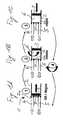
- Figure 1Ashows a metering device 1 with a cylinder 2, which has at a front or bottom a single opening 2a.
- the opening 2ais connected to a supply line 4, which is connected to a not shown, for example, pressurized reservoir containing a metered substance to be dispensed, such as insulin.
- a movable piston 3is arranged in the cylinder 2.
- FIG. 1Bshows the metering device 1 according to Figure 1A after metering the metering unit 2, 3 by retracting the piston 3 within the cylinder 2, whereby a metered substance to be dispensed through the supply line 4 was introduced into the variable volume 6 of the cylinder 2.
- the cylinder 2has already been rotated a part about its longitudinal axis after completion of the filling, as indicated by the arrow, so that the opening 2a of the cylinder 2 is no longer connected to the supply line 4 or is in fluid communication with this.
- the opening 2ais in the in FIG. 1B shown in the direction of the derivative 5 has been shifted or rotated, wherein in the in FIG. 1B shown intermediate state, the opening 2a is closed by means of a voltage applied to the cylinder 2 seal 7.
- the cylinder 2If the cylinder 2 is rotated until the opening 2a abuts the drain 5, as in Figure 1C 2, by inserting the piston 3 into the cylinder 2, the metered substance contained in the volume 6 can be delivered through the opening 2a to the drain 5, which is connected to an infusion set or a needle (not shown). After partial or complete discharge of the substance contained in the variable volume 6 of the cylinder 2, the cylinder 2 can be rotated, for example, with the piston 3 fully inserted into the cylinder 2 so that the opening 2a rests against the supply line 4 again, as in FIG FIG. 1 indicated by the state (4), so that the in FIG. 1 cycle can be run again.
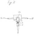
- FIG. 2shows an embodiment of the metering device according to the invention with a made of plastic or eg elastic material rotatable cylinder 2, which between two lines 4, 5, for example made of elastic material and eg also within a Sealing sleeve is arranged with eg two openings.
- the supply line 4 shown on the leftthe variable volume 6 can be filled within the cylinder 2 by the retraction of the piston 3 with a metered substance to be dispensed when the provided on a side surface or the cylinder jacket opening 2a in conjunction with the supply line 4.
- the opening 2amay be a simple hole in the plastic cylinder 2, which closes by the elastic property of the material of the cylinder 2 and which allows passage of a substance only when a pressure or suction acts on the substance, such as by the withdrawal or insertion of the piston 3 in the cylinder. 2
- the cylinder 2After the metering of the cylinder 2, in which a substance passes through the supply line 4 through the lateral opening 2a in the cylinder 2, the cylinder 2 is rotated so in the embodiment by 180 degrees about its longitudinal axis, that the only opening 2a of the cylinder. 2 in connection in the derivative 5 stands. In this state, the piston 3 can be pushed back into the cylinder 2 to thereby displace the substance contained in the cylinder 2 and to discharge through the open self-closing opening 2a of the cylinder 2 to the drain 5, which is connected to an infusion set (not shown) is.
- the cylinder 2can be turned back again or further rotated until the lateral opening 2a of the cylinder 2 is again in fluid communication with the supply line 4, to receive again a metered substance to be dispensed through the supply line 4.
- FIG. 3shows a circular process, which illustrates a functional sequence during dosing with an embodiment of the dosing device according to the invention.
- sealing elements 7 and 8are provided in the embodiment shown, which are arranged around the openings of the supply line 4 and the discharge line 5 around and a leakage of the to prevent in these lines 4, 5 guided substance or liquid.
- the seals 7 and 8may consist of disc-shaped or annular elements, for example, as in FIG. 3I shown, which are formed for example by an elastic material, wherein the cylinder 2 or an end face of the cylinder 2 preferably can easily slide over the sealing elements 7 and 8.
- VOL cylindermax .
- the cylinder 2is rotated about its longitudinal axis, as in Figure 3D shown to switch from the filling operation of the cylinder 2 to the dispensing operation.
- the rotation of the cylinder 2is carried out until the opening 2a is located on the discharge line 5, as in FIG. 3E shown, so that a fluid connection between the variable volume 6 of the cylinder 2 and the discharge line 5 is made through the opening 2a.
- the piston 3is retracted into the cylinder 2, as in FIG. 3F shown, the substance contained in the variable volume 6 is discharged through the opening 2a and the drain 5, for example, to an infusion set. This can be done until the cylinder 2 is completely or almost completely emptied, as in Figure 3G shown. In this case, the piston 3 is retracted as far as possible to a front or discharge end of the cylinder 2 in this.
- the metering unitare switched back to replenish after the dispensing process, the variable volume 6 again.
- the cylinder 2is again rotated so that the opening 2a is again in front of the feed line 4, as in FIG. 3A shown.
- Turning around or moving the cylinder 2, as in the Figures 3D and 3H shown,can be done either by a rotation in the same direction, ie, for example, relative to the longitudinal axis of the cylinder always clockwise or always counterclockwise.
- the cylinder 2it is also possible for the cylinder 2 to switch from a refilling operation to the dispensing operation, as in FIG Figure 3D is rotated in a first direction, such as to the left, and to switch from the dispensing operation to the refilling operation, as in FIG. 3H
- Thisis particularly advantageous when a reciprocating motion of the plug 3 is to be realized with a single motor, wherein the motor also for reciprocating or rotating the Cylinder 2 is used.
- FIG. 3Ishows in perspective view a sealing element 7, 8 with the passage opening 7a or 8a arranged therein, to which the supply line 4 in the states according to FIGS. 3A to 3C or the derivative 5 in the states according to Figures 3E to 3G followed.
- FIG. 4shows a further embodiment of the invention, wherein the functional sequence similar to FIG. 3 is and has a cylinder 2 at its end serving for filling and dispensing openings 2a and 2b, which, for example, based on a center of the end face of the cylinder 2 may be arranged opposite to each other.
- a sealing element 7is arranged, in which a through opening 7a is provided; please refer Fig. 4I ,
- the sealing element 7is relative to the cylinder 2 and the supply line 4, and the discharge line 5, rotatable or movable.
- the cylinder 2, the supply line 4 and the discharge line 5are in a defined or fixed positional relationship.
- the opening 7a of the sealing element 7is in a position in which a fluid connection between the supply line 4 and the variable volume 6 can be made.
- the sealing element 7is rotated about its central axis M, as in Figure 4D shown until the opening 7 a of the sealing element 7 is arranged so that the supply port 2 a of the cylinder 2 is closed and the discharge port 2 b of the cylinder with the discharge line 5 is fluidically coupled to the in the Figures 4E, 4F and 4G To perform shown dispensing process.
- FIG. 4Ishows a perspective view of the sealing element 7 with an offset from the center or pivot point M of the sealing element 7 in the radial direction passage or passage piece 7a.
Landscapes
- Health & Medical Sciences (AREA)
- Engineering & Computer Science (AREA)
- Heart & Thoracic Surgery (AREA)
- Public Health (AREA)
- Biomedical Technology (AREA)
- Anesthesiology (AREA)
- Hematology (AREA)
- Life Sciences & Earth Sciences (AREA)
- Animal Behavior & Ethology (AREA)
- General Health & Medical Sciences (AREA)
- Veterinary Medicine (AREA)
- Vascular Medicine (AREA)
- Physics & Mathematics (AREA)
- Fluid Mechanics (AREA)
- General Physics & Mathematics (AREA)
- Mechanical Engineering (AREA)
- General Engineering & Computer Science (AREA)
- Pulmonology (AREA)
- Infusion, Injection, And Reservoir Apparatuses (AREA)
- Medical Preparation Storing Or Oral Administration Devices (AREA)
Abstract
Translated fromGermanDescription
Translated fromGermanDie vorliegende Erfindung bezieht sich auf eine Dosier- und Fordervorrichtung und insbesondere auf eine Vorrichtung zum Dosieren einer zum Beispiel mittels eines Infusions-Sets an einen Patienten abzugebende Substanz.The present invention relates to a dosing and Fordervorrichtung and in particular to a device for dosing a dispensed example by means of an infusion set to a patient substance.
Aus der
Die
Die
Aus der
Aus der
Die
Die
Aus der
Die
Es ist eine Aufgabe der vorliegenden Erfindung eine Dosiervorrichtung für ein Infusionssystem vorzuschlagen, welche ein einfaches und genaues Dosieren einer abzugebenden Substanz ermöglicht.It is an object of the present invention to propose a dosing device for an infusion system, which allows a simple and accurate dosing of a substance to be dispensed.
Diese Aufgabe wird durch eine Dosiervorrichtung gemäß Anspruch 1 gelöst. Vorteilhafte Ausführungsformen ergeben sich aus den abhängigen Ansprüchen.This object is achieved by a metering device according to
Eine Dosiervorrichtung für ein Infusionssystem weist eine Dosiereinheit mit einem veränderbaren Volumen, wie zum Beispiel einen Zylinder mit einem sich in dem Zylinder bewegenden und das Volumen vergrößernden oder verkleinernden Kolben auf. Die Dosiervorrichtung hat einen Zufuhr- und einen Abgabeanschluss, welcher vorzugsweise durch einen einzigen Anschluss, wie zum Beispiel eine einzige Öffnung, z.B, am Zylinder oder an einem Anschlussteil oder an einer Hülse, gebildet wird und ist ansonsten vorzugsweise geschlossen. Durch die Zufuhr- und Abgabeöffnung kann das veränderbare Volumen der Dosiereinheit mit der abzugebenden Substanz zum Beispiel aus einem Vorratsbehälter, wie zum Beispiel einer Ampulle, gefüllt werden, wenn sich das Volumen der Dosiereinheit vergrößert. Wird das veränderbare Volumen der gefüllten Dosiereinheit wieder verkleinert, kann durch die Abgabeöffnung die dosiert abzugebende Substanz wieder ausgegeben werden. Bevorzugt ist die Dosiervorrichtung so ausgebildet, dass der Zufuhr- und Abgabeanschluss, also zum Beispiel die einzige Öffnung der Dosiereinheit, bevorzugt alternierend mit einem Vorratsbehälter, wie zum Beispiel einer Ampulle, und einer Abgabe- oder Verabreichungseinheit, wie zum Beispiel einem Infusions-Set, verbunden werden kann.A dosing device for an infusion system has a variable volume dosing unit, such as a cylinder with a piston moving in the cylinder and volume increasing or decreasing volume. The metering device has a supply and a discharge port, which is preferably formed by a single port, such as a single port, e.g., on the cylinder or on a port or sleeve, and is otherwise preferably closed. Through the supply and discharge opening, the variable volume of the dosing unit can be filled with the substance to be dispensed, for example from a storage container, such as an ampoule, as the volume of the dosing unit increases. If the variable volume of the filled metering unit is reduced again, the metered substance to be dispensed can be dispensed again through the discharge opening. Preferably, the metering device is designed so that the supply and discharge port, so for example the only opening of the metering unit, preferably alternately with a reservoir, such as an ampoule, and a dispensing or administering unit, such as an infusion set, can be connected.
Erfindungsgemäß kann somit ein Leck oder ein unbeabsichtigt und unkontrolliertes Durchtreten einer Substanz aus einem Reservoir zu einer Abgabeeinheit, wie einem Infusions-Set, verhindert werden, da die Dosiereinheit entweder nur mit dem Reservoir oder nur mit der Verabreichungsvorrichtung gekoppelt ist, Das Reservoir ist somit von der Verabreichungseinheit vollständig entkoppelt, also das Reservoir ist vorteilhaft nie direkt mit dem Ausgang verbunden.Thus, according to the present invention, leakage or inadvertent and uncontrolled passage of a substance from a reservoir to a delivery unit, such as an infusion set, can be prevented because the dosing unit is coupled either to the reservoir only or to the delivery device only the administration unit completely decoupled, so the reservoir is advantageously never connected directly to the output.
Der Zufuhr- und Abgabenanschluss kann auch durch mehrere Öffnungen gebildet werden, welche dann immer so mit einem externen Anschluss verbunden sein sollten, dass die Dosiereinheit durch alle oder einen Teil der Öffnungen entweder nur befüllt oder nur entleert wird, also ein gleichzeitiges Aufnehmen oder Abgeben einer Substanz nicht möglich ist. Das oder die gleichzeitig als Einlass und Auslass wirkenden Verbindungen oder Zugänge oder Löcher der Dosiereinheit ist beziehungsweise sind so koppelbar, dass sie entweder mit einem Reservoir gekoppelt werden können und somit als Einlass für die Dosiereinheit wirken, oder mit einer Verabreichungsvorrichtung, wie zum Beispiel einem Infusionsgerät, gekoppelt werden können, und so als Auslass für die Dosiereinheit wirken. Vorzugsweise sind die Anschlüsse der Dosiereinheit verschlossen, wenn keine Substanz aufgenommen oder abgegeben wird.The supply and discharge port can also be formed by a plurality of openings, which should then always be connected to an external terminal, that the metering unit is either only filled or only emptied through all or part of the openings, ie a simultaneous recording or dispensing one Substance is not possible. The one or more inlet-outlet connections or ports or holes of the dosing unit are coupled so that they can either be coupled to a reservoir and thus act as an inlet to the dosing unit, or with an administering device such as an infusion device , can be coupled, and so act as an outlet for the metering unit. The connections of the dosing unit are preferably closed when no substance is taken up or dispensed.
Es ist auch möglich in einer Ruheposition zwischen einer Abgabe oder Aufnahme einer Substanz die Öffnungen aktiv z.B. durch ein verschiebbares Dichtelement zu verschließen.It is also possible in a rest position between delivery or reception of a substance to actively expose the openings e.g. to close by a sliding sealing element.
Beispielsweise kann die Dosiereinheit verschiebbar oder drehbar sein, um je nach Verschiebeposition oder Drehstellung mit einem von zwei oder mehr externen Anschlüssen zur Befüllung der Dosiereinheit und zur Abgabe und Weiterleitung der von der Dosiereinheit abgegebenen Substanz verbunden zu werden. Ebenso können auch einer oder mehrere der externen Anschlüsse verschiebbar oder drehbar an der Dosiereinheit vorgesehen sein, so dass die verschiebbaren Anschlüsse zum Beispiel abwechselnd mit der Zufuhr- und Abgabeöffnung der Dosiereinheit verbunden werden. Somit kann eine Ventilwirkung durch eine Art Umschaltventil erhalten werden.For example, the dosing unit can be displaceable or rotatable in order to be connected to one of two or more external connections for filling the dosing unit and for dispensing and forwarding the substance dispensed by the dosing unit, depending on the displacement position or rotational position. Likewise, one or more of the external terminals can be slidably or rotatably provided on the dosing unit, so that the displaceable connections are connected, for example, alternately to the supply and discharge opening of the dosing unit. Thus, a valve action can be obtained by a kind of switching valve.
Vorteilhaft ist ein Motor vorgesehen, mit welcher die Dosiereinheit oder der Zufuhr- und Abgabeanschluss der Dosiereinheit bewegt und zum Beispiel gedreht oder verschoben werden kann, wobei der Motor alternativ oder ergänzend auch zur Bewegung, also zum Beispiel zur Verschiebung oder Drehung, der externen Zufuhr- und Abgabeanschlüsse verwendet werden kann, um diese abwechselnd mit der Zufular- und Abgabeöffnung der Dosiereinheit zu verbinden. Ebenso kann der oder ein anderer Motor zur Vergrößerung oder Verkleinerung des Volumens zum Beispiel zur Bewegung des Kolbens verwendet werden. Vorzugsweise ist der Kolben des Zylinders so ausgebildet, dass er genau zu einer vorgegebenen Position innerhalb des Zylinders bewegt werden kann, also zum Beispiel exakt zu einer vordefinierten maximalen Auszugsstellung des Kolbens, welche sich vorteilhaft noch innerhalb des Zylinders befindet. Somit kann anders als bei bekannten so genannten "single stroke" Verfahren auch nur ein Teil des veränderbaren (Zylinder-)Volumens zur Dosierung verwendet werden.Advantageously, a motor is provided, with which the dosing unit or the supply and discharge connection of the dosing unit can be moved and, for example, rotated or displaced, wherein the motor alternatively or additionally also for movement, for example, for displacement or rotation, the external supply and delivery ports may be used to alternately connect them to the feed and delivery ports of the metering unit. Likewise, the or another motor can be used to increase or decrease the volume, for example, to move the piston. Preferably, the piston of the cylinder is designed so that it can be moved exactly to a predetermined position within the cylinder, so for example exactly to a predefined maximum extension position of the piston, which is advantageously still within the cylinder. Thus, unlike known so-called "single-stroke" methods, only a portion of the variable (cylinder) volume can be used for dosing.
Die Verbindungsstellen oder Verbindungsleitungen, welche zu dem Zufuhr- oder Abgabeanschluss der Dosiereinheit führen, weisen vorteilhaft jeweils mindestens ein Ventil auf, wobei auch nur ein einziges Ventil entweder in der Zufuhr- oder in der Abgabeleitung oder in dem Zufuhr- und Abgabeanschluss vorgesehen sein kann, Ein solches Ventil kann in einer oder beiden der Leitungen zum Beispiel als Rückschlagventil sicherstellen, dass eine dosiert abzugebende Substanz nur in eine Richtung gefördert wird, wobei der Rückfluss der Substanz in die Gegenrichtung unterbunden oder verhindert wird.The connection points or connecting lines which lead to the supply or discharge connection of the dosing unit advantageously each have at least one valve, wherein only a single valve may be provided either in the supply or in the delivery line or in the supply and discharge connection, Such a valve can ensure in one or both of the lines, for example as a check valve, that a substance to be dispensed in a metered manner is conveyed only in one direction, whereby the return flow of the substance in the opposite direction is prevented or prevented.
Das oder die verwendeten Ventile am oder in den Zu- und Ableitungen und/oder an oder in der Dosiereinheit können Rückschlagventile sein, welche einen Fluss einer Substanz oder einer Flüssigkeit nur in eine Richtung ermöglichen oder können auch als Überdruckventile ausgebildet sein, welche einen Durchgang eines Materials oder einer Flüssigkeit erst nach Anliegen eines Mindestdruckes ermöglichen.The one or more valves used on or in the feed and discharge lines and / or on or in the metering unit may be check valves, which allow a flow of a substance or a liquid in one direction only or may also be designed as pressure relief valves, which is a passage of a Material or a liquid only after applying a minimum pressure allow.
Der Vorratsbehälter, welcher die nach Durchlauf durch die Dosiervorrichtung dosiert abzugebende Substanz enthält, kann druckbeaufschlagt oder drucklos sein. Beispielsweise kann der Vorratsbehälter eine Ampulle sein, in welcher ein druckbeaufschlagter Stopfen auf die abzugebende Substanz einwirkt, so dass die abzugebende Substanz nur noch dosiert werden muss und keine weitere Energie für die eigentliche Substanzabgabe aus der Ampulle bzw, das Aufdosieren oder Umfüllen in den Mikrodosierzylinder benötigt wird. Die Druckbeaufschlagung des Stopfens kann beispielsweise mittels einer Feder oder eines unter Überdruck stehenden Gases erfolgen. Ebenso kann der Vorratsbehälter einen elastischen Bereich aufweisen oder vollständig aus einem elastischen Material gebildet sein, wie zum Beispiel ein Beutel, welcher mit der abzugebenden Substanz gefüllt ist. Auf den elastischen Bereich oder Beutel kann zum Beispiel mittels einer Feder eine Kraft oder ein Druck einwirken, um die in dem Vorratsbehälter enthaltene Substanz zu verdrängen und abzugeben, wenn dies durch die dem Vorratsbehälter nachgeschaltete Dosiervorrichtung ermöglicht wird.The storage container, which contains the metered after passage through the metering substance to be dispensed substance may be pressurized or depressurized. For example, the reservoir may be an ampoule in which a pressurized plug acts on the substance to be dispensed, so that the substance to be dispensed only needs to be dispensed and no further energy for the actual substance release from the ampoule or, the metering or transfer into the microdosing required becomes. The pressurization of the plug can be done for example by means of a spring or a pressurized gas. Likewise, the reservoir may have an elastic region or be formed entirely of an elastic material, such as a bag, which is filled with the substance to be dispensed. For example, a force or a pressure can act on the elastic region or pouch by means of a spring in order to displace and dispense the substance contained in the reservoir, if this is made possible by the dosing device connected downstream of the reservoir.
Vorzugsweise ist ein Vorratsbehälter oder Reservoir so ausgelegt oder konstruiert, dass bei einem Ausgang oder einer Abgabeöffnung des Reservoirs ein positiver Druck anliegt, was zum Beispiel durch mit Kraft oder Druck beaufschlagte Behälter oder Beutel, oder durch einen aktiven Antriebsmechanismus, welcher auf ein Verdrängungselement des Reservoirs oder das Reservoir selbst einwirkt, erreicht werden kann,Preferably, a reservoir or reservoir is designed or constructed such that positive pressure is applied to an exit or discharge opening of the reservoir, such as by pressurized containers or bags, or by an active drive mechanism acting on a displacement element of the reservoir or the reservoir itself acts, can be achieved
Vorzugsweise weist die Dosiervorrichtung mindestens einen Sensor zur Überprüfung der Funktionsfähigkeit oder zur Feststellung einer Fehlfunktion auf, wie zum Beispiel einen Leck-Sensor, galvanischen oder Leitwertsensor, einen Blasen-Sensor, einen Druck-Sensor oder einen Kraftsensor, welche zum Beispiel feststellen können, ob eine Substanz oder Flüssigkeit aus der Dosiervorrichtung ausgetreten ist, ob zum Beispiel Blasen in der abzugebenden Substanz enthalten sind, oder ob zum Beispiel eine Okklusion vorliegt. Dieser mindestens eine Sensor kann mit einer Warn- oder Alarmanzeige oder einer Steuerung der Dosiervorrichtung verbunden sein, um die Dosiervorrichtung zum Beispiel abzuschalten, wenn eine Fehlfunktion festgestellt wird oder um im Falle einer festgestellten Störung der Dosiervorrichtung ein zum Beispiel optisches oder akustisches Alarmsignal auszugeben.Preferably, the dosing device has at least one sensor for checking the functionality or detecting a malfunction, such as a leak sensor, galvanic or Leitwertsensor, a bubble sensor, a pressure sensor or a force sensor, which can determine, for example, whether a substance or liquid has leaked out of the metering device, whether, for example, bubbles are contained in the substance to be dispensed, or if, for example, there is an occlusion. This at least one sensor can be equipped with a warning or alarm display or a control of Metering device may be connected to turn off the metering device, for example, if a malfunction is detected or to issue in the case of a detected malfunction of the metering device, for example, an optical or audible alarm signal.
Vorteilhaft wird ein gas- oder luftdurchlässiges Material für die Dosiervorrichtung und/oder eine Verbindungsleitung der Dosiervorrichtung, wie zum Beispiel eine Zuführleitung oder eine Abgabeleitung, verwendet. Ist in der abzugebenden Substanz Luft oder ein Gas vorhanden, so kann ein zum Beispiel luftdurchlässiger Zuführschlauch, welcher die Dosiervorrichtung mit dem Vorratsbehälter verbindet und somit der Dosierung vorgeschaltet ist, die Möglichkeit schaffen, dass das in der abzugebenden Substanz enthaltene Gas, welches zusammen mit der Substanz durch diese Leitung geführt wird, entweichen kann, um im Idealfall in der Dosiereinheit keine Gaseinschlüsse mehr in der Substanz zu haben.Advantageously, a gas or air-permeable material for the metering device and / or a connecting line of the metering device, such as a supply line or a discharge line is used. If there is air or a gas in the substance to be dispensed, an air-permeable supply hose, for example, which connects the metering device to the reservoir and thus precedes the metering, can create the possibility that the gas contained in the substance to be dispensed can be used together with the Substance is passed through this line, can escape, in the ideal case in the dosing unit no more gas inclusions in the substance.
Vorzugsweise ist an der Dosiervorrichtung eine Dichtung, wie zum Beispiel eine Dichtungsmanschettc, vorgesehen, um den Zufuhr- und Abgabeanschluss der Dosiereinheit abzudichten, wenn dieser Anschluss nicht mit einer Zufuhr- oder Abgabeleitung verbunden ist und zum Beispiel mit der Dosiereinheit von der Verbindung mit der Zufuhrleitung zu der Verbindung mit der Abgabeleitung gedreht wird.Preferably, a seal, such as a gasket, is provided on the metering device to seal the supply and discharge ports of the metering unit when this port is not connected to a supply or discharge line and, for example, to the metering unit from the connection to the supply line is turned to the connection with the discharge line.
Die Dosiervorrichtung ist vorzugsweise so ausgelegt, dass das Maximalvolumen des veränderbaren Volumens der Dosiereinheit VOLZylinder,max, also zum Beispiel das Volumen eines Zylinders bei einem fast oder vollständig herausgezogenen Kolben, kleiner ist als das 0,1-fache Volumen des Vorratsbehälters oder eines Reservoirs VOLReservoir, in welchem die gesamte dosiert abzugebende Substanz enthalten ist. Bevorzugt ist das maximale Volumen der Dosiereinheit größer als das 2-fache oder auch z.B. 1 0-fache des Volumens einer minimal abzugebenden Dosis VOLDose, min. Vorzugsweise ist das maximale Volumen der Dosiereinheit gleich dem minimalen Volumen der abzugebenden Dosis multipliziert mit der Wurzel aus dem Quotienten gebildet aus dem Volumen des Reservoirs und dem minimalen Volumen der minimal abzugebenden Dosis und genügt somit der Formel:
Bevorzugt ist die Dosiervorrichtung so ausgelegt dass:
- 2...10xVolDose,min< VolZylinder,max < 1/10...1/2 VolReservoir
- 2 ... 10xVolcan, min <Volcylinder, max <1/10 ... 1/2 volreservoir
Vorteilhaft ist das Verhältnis des Innendurchmessers einer zylinderförmigen Dosiereinheit zu der Zylinderlänge gleich oder etwa 1:4.Advantageously, the ratio of the inner diameter of a cylindrical metering unit to the cylinder length is equal to or about 1: 4.
Gemäß einem weiteren Aspekt bezieht sich die Erfindung auf ein Verfahren zur Dosierung einer aus einem Vorratsbehälter oder einem Reservoir abzugebenden Substanz, wobei die Substanz aus dem Vorratsbehälter oder Reservoir über oder durch einen einzigen Anschluss oder eine Öffnung in eine Dosiereinheit mit einem veränderbaren und im Falle der Aufdosierung sich vergrößernden Volumen gebracht wird, der Anschluss oder die Öffnung nach dem Aufdosieren oder Auffüllen des zur Auffüllung sich vergrößernden Volumens mit einer Abgabeleitung verbunden wird und anschließend das die Substanz enthaltende Volumen wieder verkleinert wird, um durch den Anschluss oder diese Öffnung die Substanz dosiert abzugeben.According to a further aspect, the invention relates to a method for dosing a substance to be dispensed from a reservoir or a reservoir, wherein the substance from the reservoir or reservoir via or through a single port or an opening in a variable-dose unit and in the case of As the volume increases, the connection or opening is connected to a discharge line after the metering or filling of the volume to be filled up, and the volume containing the substance is then reduced again in order to dispense the substance through the connection or opening ,
Vorteilhaft wird die Dosiereinheit nach dem Befüllen des veränderbaren Volumens mit der abzugebenden Substanz verschoben oder gedreht, um die Öffnung der Dosiereinheit von der Zufuhrleitung zu entkoppeln und mit der Abgabeleitung zu verbinden.After the variable volume has been filled, the dosing unit is advantageously displaced or rotated with the substance to be dispensed, in order to decouple the opening of the dosing unit from the supply line and to connect it to the dispensing line.
Erfindungsgemäß kann somit durch eine Dosiervorrichtung unabhängig von der Ausbildung und Größe eines Reservoirs oder eines Vorratsbehälters eine genaue Dosierung der abzugebenden Substanz vorgenommen werden, wobei die Dosiereinheit im Falle der Verwendung einer einzigen Zufuhr- und Abgabeöffnung ein relativ kleines Leck- oder Dichtungsrisiko aufweist.According to the invention can thus be made by a metering device, regardless of the formation and size of a reservoir or a reservoir, a precise dosage of the substance to be dispensed, wherein the metering unit in the case of using a single supply and discharge opening has a relatively small leakage or sealing risk.
Die Erfindung wird nachfolgend anhand von Ausführungsbeispielen beschrieben, wobei die beiliegenden Figuren zeigen:
- Figuren 1A, B, C
- einen prinzipiellen Funktionsablauf beim Dosieren mit der Dosiervorrichtung;
- Figur2
- eine Ausführungsform der Dosiervorrichtung;
Figur 3- einen Kreisprozess bei einer Ausführungsform der Erfindung; und
Figur 4- einen Kreisprozess bei einer weiteren Ausführungsform der Erfindung.
- FIGS. 1A, B, C
- a basic functional sequence when dosing with the metering device;
- Figur2
- an embodiment of the metering device;
- FIG. 3
- a cyclic process in one embodiment of the invention; and
- FIG. 4
- a cyclic process in another embodiment of the invention.
Wird der Zylinder 2 so weit gedreht, bis die Öffnung 2a an der Ableitung 5 anliegt, wie in
Nach dem Aufdosieren des Zylinders 2, bei welchem eine Substanz über die Zuleitung 4 durch die seitliche Öffnung 2a in den Zylinder 2 gelangt, wird der Zylinder 2 so gedreht, im Ausführungsbeispiel um 180 Grad um seine Längsachse, dass die einzige Öffnung 2a des Zylinders 2 in Verbindung in der Ableitung 5 steht. In diesem Zustand kann der Kolben 3 wieder in den Zylinder 2 eingeschoben werden, um dadurch die in dem Zylinder 2 enthaltene Substanz zu verdrängen und durch die geöffnete selbst schließende Öffnung 2a des Zylinders 2 an die Ableitung 5 abzugeben, welche mit einem nicht gezeigten lnfusionsset verbunden ist.After the metering of the
Anschließend kann der Zylinder 2 wieder zurückgedreht oder weitergedreht werden, bis die seitliche Öffnung 2a des Zylinders 2 wieder in Fluid-Verbindung mit der Zuleitung 4 steht, um erneut eine dosiert abzugebende Substanz durch die Zuleitung 4 aufzunehmen.Subsequently, the
An der Vorderseite bzw. der Verbindungs- oder Kontaktseite der Zuleitung 4 und der Ableitung 5 mit dem Zylinder 2 sind in der gezeigten Ausführungsform Dichtelemente 7 und 8 vorgesehen, welche um die Öffnungen der Zuleitung 4 und der Ableitung 5 herum angeordnet sind und ein Austreten der in diesen Leitungen 4, 5 geführten Substanz oder Flüssigkeit verhindern sollen. Die Dichtungen 7 und 8 können z.B. aus scheibenförmigen oder ringförmigen Elementen bestehen, wie in
Wie aus
Anschließend wird der Zylinder 2 um seine Längsachse gedreht, wie in
Wird nun der Kolben 3 wieder in den Zylinder 2 eingefahren, wie in
Anschließend kann, wie in
Das Hin- und Herdrehen oder Bewegen des Zylinders 2, wie in den
Während des Auffüllvorganges, wie in dem Ablauf der
Anschließend kann von dem Abgabevorgang wieder in den Auffüllvorgang umgeschaltet werden, wie in
Claims (14)
Translated fromGermanPriority Applications (21)
| Application Number | Priority Date | Filing Date | Title |
|---|---|---|---|
| DE502007001678TDE502007001678D1 (en) | 2007-03-15 | 2007-03-15 | Infusion system with a dosing device |
| EP07104240AEP1970677B1 (en) | 2007-03-15 | 2007-03-15 | Intravenous infusion system with dosing device |
| DK07104240.2TDK1970677T3 (en) | 2007-03-15 | 2007-03-15 | Infusion system with a dosing device |
| ES07104240TES2331546T3 (en) | 2007-03-15 | 2007-03-15 | INFUSION SYSTEM WITH A DOSAGE DEVICE. |
| AT07104240TATE445145T1 (en) | 2007-03-15 | 2007-03-15 | INFUSION SYSTEM WITH A DOSING DEVICE |
| EP17179898.6AEP3258223A1 (en) | 2007-03-15 | 2008-02-26 | Dosing device for an infusion system |
| EP15165236.9AEP3012600B1 (en) | 2007-03-15 | 2008-02-26 | Dosing device for an infusion system |
| HK10105332.4AHK1139457B (en) | 2007-03-15 | 2008-02-26 | Metering device for an infusion system |
| CN2008800085407ACN101652639B (en) | 2007-03-15 | 2008-02-26 | Metering device for an infusion system |
| PCT/EP2008/001516WO2008110263A1 (en) | 2007-03-15 | 2008-02-26 | Metering device for an infusion system |
| DK15165236.9TDK3012600T3 (en) | 2007-03-15 | 2008-02-26 | Dosage device for an infusion system |
| PL15165236TPL3012600T3 (en) | 2007-03-15 | 2008-02-26 | Dosing device for an infusion system |
| EP08716055AEP2118624A1 (en) | 2007-03-15 | 2008-02-26 | Metering device for an infusion system |
| US12/559,851US7955302B2 (en) | 2007-03-15 | 2009-09-15 | Dosing device for an infusion system and method thereof |
| US13/097,880US8277423B2 (en) | 2007-03-15 | 2011-04-29 | Dosing device for an infusion system and method thereof |
| US13/097,894US8277434B2 (en) | 2007-03-15 | 2011-04-29 | Dosing device for an infusion system and method thereof |
| US13/588,042US8790316B2 (en) | 2007-03-15 | 2012-08-17 | Dosing device for an infusion system and method thereof |
| US14/308,006US9687604B2 (en) | 2007-03-15 | 2014-06-18 | Dosing device for an infusion system and method thereof |
| US15/367,580US10029046B2 (en) | 2007-03-15 | 2016-12-02 | Dosing device for an infusion system and method thereof |
| US15/384,880US10034983B2 (en) | 2007-03-15 | 2016-12-20 | Dosing device for an infusion system and method thereof |
| US15/386,026US10034977B2 (en) | 2007-03-15 | 2016-12-21 | Dosing device for an infusion system and method thereof |
Applications Claiming Priority (1)
| Application Number | Priority Date | Filing Date | Title |
|---|---|---|---|
| EP07104240AEP1970677B1 (en) | 2007-03-15 | 2007-03-15 | Intravenous infusion system with dosing device |
Publications (2)
| Publication Number | Publication Date |
|---|---|
| EP1970677A1true EP1970677A1 (en) | 2008-09-17 |
| EP1970677B1 EP1970677B1 (en) | 2009-10-07 |
Family
ID=38375237
Family Applications (4)
| Application Number | Title | Priority Date | Filing Date |
|---|---|---|---|
| EP07104240AActiveEP1970677B1 (en) | 2007-03-15 | 2007-03-15 | Intravenous infusion system with dosing device |
| EP08716055ACeasedEP2118624A1 (en) | 2007-03-15 | 2008-02-26 | Metering device for an infusion system |
| EP15165236.9AActiveEP3012600B1 (en) | 2007-03-15 | 2008-02-26 | Dosing device for an infusion system |
| EP17179898.6APendingEP3258223A1 (en) | 2007-03-15 | 2008-02-26 | Dosing device for an infusion system |
Family Applications After (3)
| Application Number | Title | Priority Date | Filing Date |
|---|---|---|---|
| EP08716055ACeasedEP2118624A1 (en) | 2007-03-15 | 2008-02-26 | Metering device for an infusion system |
| EP15165236.9AActiveEP3012600B1 (en) | 2007-03-15 | 2008-02-26 | Dosing device for an infusion system |
| EP17179898.6APendingEP3258223A1 (en) | 2007-03-15 | 2008-02-26 | Dosing device for an infusion system |
Country Status (9)
| Country | Link |
|---|---|
| US (8) | US7955302B2 (en) |
| EP (4) | EP1970677B1 (en) |
| CN (1) | CN101652639B (en) |
| AT (1) | ATE445145T1 (en) |
| DE (1) | DE502007001678D1 (en) |
| DK (2) | DK1970677T3 (en) |
| ES (1) | ES2331546T3 (en) |
| PL (1) | PL3012600T3 (en) |
| WO (1) | WO2008110263A1 (en) |
Cited By (29)
| Publication number | Priority date | Publication date | Assignee | Title |
|---|---|---|---|---|
| EP2163273A1 (en)* | 2008-09-12 | 2010-03-17 | F.Hoffmann-La Roche Ag | Dosing unit and ambulatory infusion device comprising dosing unit |
| EP2196231A1 (en) | 2008-12-12 | 2010-06-16 | F.Hoffmann-La Roche Ag | System for ambulatory drug infusion comprising a filling apparatus for flexible containers |
| EP2229967A1 (en) | 2009-03-17 | 2010-09-22 | F. Hoffmann-La Roche AG | Cannula assembly and ambulatory infusion system with a pressure sensor made of stackes coplanar layers |
| EP2322238A1 (en) | 2009-11-11 | 2011-05-18 | F. Hoffmann-La Roche AG | Device and method for determining the fill level of a flexible medicine reservoir |
| WO2012019726A1 (en) | 2010-08-07 | 2012-02-16 | Roche Diagnostics Gmbh | Valve for an ambulatory infusion system and ambulatory infusion system including a valve |
| EP2455126A1 (en) | 2010-11-15 | 2012-05-23 | F. Hoffmann-La Roche AG | Container for storing medical or pharmaceutical liquids |
| EP2457602A1 (en) | 2010-11-25 | 2012-05-30 | F. Hoffmann-La Roche AG | Infusion pump having dosing unit with safety valve |
| EP2469432A1 (en) | 2010-12-24 | 2012-06-27 | F. Hoffmann-La Roche AG | Ambulatory infusion system with alert prioritizing features |
| EP2503312A1 (en) | 2011-03-22 | 2012-09-26 | F. Hoffmann-La Roche AG | Sensor device for use in a medical fluid delivery system |
| US8277423B2 (en) | 2007-03-15 | 2012-10-02 | Roche Diagnostics International Ag | Dosing device for an infusion system and method thereof |
| EP2510962A1 (en) | 2011-04-12 | 2012-10-17 | F. Hoffmann-La Roche AG | Infusion pump device with re-filling scheme for cylinder-piston dosing unit |
| EP2510961A1 (en) | 2011-04-12 | 2012-10-17 | F. Hoffmann-La Roche AG | Infusion pump device with improved priming of the fluidic system and method for priming such an infusion pump device |
| EP2510960A1 (en) | 2011-04-12 | 2012-10-17 | F. Hoffmann-La Roche AG | Infusion pump device with cylinder-piston dosing unit and optical piston position detection |
| WO2013029999A1 (en)* | 2011-09-02 | 2013-03-07 | F. Hoffmann-La Roche Ag | Dosing unit for an ambulatory infusion device |
| EP2815778A1 (en) | 2013-06-21 | 2014-12-24 | F. Hoffmann-La Roche AG | Portable infusion device for infants with refillable small volume dosing unit |
| EP2881128A1 (en) | 2013-12-04 | 2015-06-10 | F. Hoffmann-La Roche AG | Ambulatory infusion system including a step switching mechanism for valve control |
| EP2921189A1 (en) | 2014-03-17 | 2015-09-23 | F. Hoffmann-La Roche AG | Initalization of a dosing unit for drug infusion |
| US9421327B2 (en) | 2011-09-02 | 2016-08-23 | Roche Diagnostics International Ag | Dosing unit for an ambulatory infusion device |
| EP3138597A1 (en) | 2015-09-03 | 2017-03-08 | F. Hoffmann-La Roche AG | Dosing unit with low radial sealing forces during storage |
| EP3138593A1 (en) | 2015-09-03 | 2017-03-08 | F. Hoffmann-La Roche AG | Valve clutch device and dosing unit with a valve clutch device |
| WO2018007502A1 (en) | 2016-07-08 | 2018-01-11 | Roche Diabetes Care Gmbh | Flow detector |
| WO2018007361A1 (en) | 2016-07-05 | 2018-01-11 | Roche Diabetes Care Gmbh | Infusion device drive unit with blocking device |
| EP3290071A1 (en) | 2016-09-06 | 2018-03-07 | Roche Diabetes Care GmbH | Supervsion device for ambulatroy infusion |
| EP3335745A1 (en) | 2016-12-14 | 2018-06-20 | Roche Diabetes Care GmbH | Ambulatory infusion system initialization |
| EP3335746A1 (en) | 2016-12-14 | 2018-06-20 | Roche Diabetes Care GmbH | Ambulatory infusion device |
| EP3441975A1 (en) | 2017-08-09 | 2019-02-13 | Roche Diabetes Care GmbH | Dosing unit refilling schedule |
| WO2019162098A1 (en) | 2018-02-23 | 2019-08-29 | Roche Diabetes Care Gmbh | Dosing unit refilling scheduling |
| US11071819B2 (en) | 2016-06-07 | 2021-07-27 | Roche Diabetes Care, Inc. | Valve drive unit with shape memory alloy actuator |
| RU2784997C2 (en)* | 2018-02-23 | 2022-12-01 | Ф. Хоффманн-Ля Рош Аг | Planning of refueling of dosing device |
Families Citing this family (16)
| Publication number | Priority date | Publication date | Assignee | Title |
|---|---|---|---|---|
| US9133833B2 (en)* | 2008-12-04 | 2015-09-15 | Alltech Associates, Inc. | Methods and apparatus for moving aliquot samples of fluid |
| DK2371408T3 (en) | 2010-03-31 | 2013-11-04 | Hoffmann La Roche | Liquid drug degassing device and outpatient infusion system containing a degassing device |
| ES2666795T3 (en) | 2012-05-08 | 2018-05-07 | Roche Diagniostics Gmbh | Cartridge for dispensing a fluid |
| EP2862586B1 (en) | 2013-10-21 | 2021-09-01 | F. Hoffmann-La Roche AG | Control unit for infusion pump units, including a controlled intervention unit |
| DK2865325T3 (en) | 2013-10-23 | 2018-02-19 | Hoffmann La Roche | STANDING ON THE SKIN OF INFUSION PUMP OR CONTINUOUS BLOOD SUGAR MONITOR WITH OPTICAL INDICATION ORGANIZATION |
| US9416775B2 (en)* | 2014-07-02 | 2016-08-16 | Becton, Dickinson And Company | Internal cam metering pump |
| ES2985905T3 (en) | 2016-11-22 | 2024-11-07 | Lts Device Tech Ltd | Apparatus for delivering a therapeutic substance |
| EP3381560A1 (en)* | 2017-03-28 | 2018-10-03 | Eppendorf AG | Method and a dosing device for contact dosing of liquids |
| EP3697470A1 (en)* | 2017-10-19 | 2020-08-26 | Sanofi | A medical pump |
| US11174852B2 (en) | 2018-07-20 | 2021-11-16 | Becton, Dickinson And Company | Reciprocating pump |
| IT201800007477A1 (en)* | 2018-07-24 | 2020-01-24 | EQUIPMENT FOR THE STORAGE OF A HUMAN BREATH SAMPLE AND RELATED PROCEDURE FOR THE STORAGE OF A HUMAN BREATH SAMPLE | |
| ES2986346T3 (en) | 2018-10-05 | 2024-11-11 | Lts Device Tech Ltd | Activation sequence |
| US11034468B2 (en)* | 2019-08-22 | 2021-06-15 | Chin-Tui Lin | Filling machine |
| US12232708B2 (en)* | 2020-02-11 | 2025-02-25 | Andrea Munoz | Vaginal speculum and related methods |
| US12138418B2 (en)* | 2021-11-24 | 2024-11-12 | Medtronic, Inc. | Fluid drug spread-promoting pump |
| EP4393575A1 (en)* | 2022-12-28 | 2024-07-03 | Eveon | Mixing device and mixing method |
Citations (11)
| Publication number | Priority date | Publication date | Assignee | Title |
|---|---|---|---|---|
| US3631654A (en)* | 1968-10-03 | 1972-01-04 | Pall Corp | Gas purge device |
| DE3832028A1 (en)* | 1988-09-21 | 1990-03-22 | Minh Bach Dr Ing Dr Med Quang | DEVICE FOR VENTING LIQUIDS FLOWING IN MEDICAL LIQUID SYSTEMS |
| WO1993004714A1 (en) | 1991-08-30 | 1993-03-18 | Infusaid, Inc. | Metering device for implantable delivery system |
| US5807321A (en) | 1995-11-28 | 1998-09-15 | Merit Medical | System for electronically monitoring the delivery of contrast media |
| EP0980690A2 (en) | 1998-08-19 | 2000-02-23 | Weston Medical Limited | Device for metered fluid delivery |
| US20040069044A1 (en) | 1999-04-29 | 2004-04-15 | Gilad Lavi | Device for measuring a volume of drug |
| EP1486218A2 (en)* | 1998-09-08 | 2004-12-15 | Disetronic Licensing AG | Remote control and monitoring device for a drug delivery device |
| US20050159708A1 (en) | 2002-07-24 | 2005-07-21 | Rudolf Sidler | Infusion pump, control program, semiconductor means and method for the dosed administration of a medicinal liquid |
| WO2007000064A1 (en) | 2005-06-29 | 2007-01-04 | F. Hoffmann-La Roche Ag | Micro-dosing device for liquid materials |
| EP1633417B1 (en) | 2003-05-30 | 2007-01-31 | Eli Lilly And Company | Multiple chamber medication dispensing apparatus |
| EP1754505A1 (en) | 2005-08-19 | 2007-02-21 | The Automation Partnership (Cambridge) Limited | Syringe pump |
Family Cites Families (16)
| Publication number | Priority date | Publication date | Assignee | Title |
|---|---|---|---|---|
| NL8403937A (en) | 1984-12-24 | 1986-07-16 | Cornelis Smit | DEVICE FOR DELIVERING A NUMBER OF LIQUID DOSES. |
| US5014750A (en)* | 1988-03-14 | 1991-05-14 | Baxter International Inc. | Systems having fixed and variable flow rate control mechanisms |
| US5033714A (en)* | 1988-03-14 | 1991-07-23 | Baxter International Inc. | Systems having fixed and variable flow rate control mechanisms |
| US5100389A (en)* | 1988-06-21 | 1992-03-31 | Vaillancourt Vincent L | Ambulatory infusion pump |
| DK47992D0 (en)* | 1992-04-10 | 1992-04-10 | Novo Nordisk As | APPARATUS |
| ES2137243T3 (en)* | 1993-10-01 | 1999-12-16 | Wilhelm A Keller | DEVICE FOR MEASURING FLUIDS. |
| CH688224A5 (en) | 1994-06-03 | 1997-06-30 | Saphirwerk Ind Prod | Implanted dosing unit for e.g. controlled, long term delivery of insulin |
| ES2169380T3 (en) | 1996-09-20 | 2002-07-01 | Novo Nordisk As | OPERATING CYLINDER |
| US6179583B1 (en)* | 1997-02-25 | 2001-01-30 | Weston Medical Limited | Metered fluid delivery device |
| US5961303A (en)* | 1997-11-18 | 1999-10-05 | King; Kenyon M. | Positive displacement dispensing pump system |
| US6568923B2 (en) | 2000-12-21 | 2003-05-27 | Kazumasa Ikuta | Fluid suction and discharge apparatus |
| EP1381408A4 (en) | 2001-02-22 | 2007-06-13 | Insulet Corp | Modular infusion device and method |
| CN101429932A (en)* | 2004-11-29 | 2009-05-13 | 蒂埃里·那瓦罗 | Positive displacement pump with reciprocating rotary piston |
| ITBO20060276A1 (en) | 2006-04-13 | 2007-10-14 | Arcotronics Technologies Srl | VOLUMETRIC DOSING DEVICE AND RELATIVE HANDLING DEVICE |
| BRPI0711250A2 (en)* | 2006-06-02 | 2011-08-30 | Nomet Man Services B V | volumetric pump and drive mechanism for a volumetric pump |
| EP1970677B1 (en)* | 2007-03-15 | 2009-10-07 | F. Hoffmann-La Roche AG | Intravenous infusion system with dosing device |
- 2007
- 2007-03-15EPEP07104240Apatent/EP1970677B1/enactiveActive
- 2007-03-15ATAT07104240Tpatent/ATE445145T1/enactive
- 2007-03-15DKDK07104240.2Tpatent/DK1970677T3/enactive
- 2007-03-15ESES07104240Tpatent/ES2331546T3/enactiveActive
- 2007-03-15DEDE502007001678Tpatent/DE502007001678D1/enactiveActive
- 2008
- 2008-02-26DKDK15165236.9Tpatent/DK3012600T3/enactive
- 2008-02-26EPEP08716055Apatent/EP2118624A1/ennot_activeCeased
- 2008-02-26WOPCT/EP2008/001516patent/WO2008110263A1/enactiveApplication Filing
- 2008-02-26CNCN2008800085407Apatent/CN101652639B/enactiveActive
- 2008-02-26EPEP15165236.9Apatent/EP3012600B1/enactiveActive
- 2008-02-26PLPL15165236Tpatent/PL3012600T3/enunknown
- 2008-02-26EPEP17179898.6Apatent/EP3258223A1/enactivePending
- 2009
- 2009-09-15USUS12/559,851patent/US7955302B2/enactiveActive
- 2011
- 2011-04-29USUS13/097,880patent/US8277423B2/enactiveActive
- 2011-04-29USUS13/097,894patent/US8277434B2/enactiveActive
- 2012
- 2012-08-17USUS13/588,042patent/US8790316B2/enactiveActive
- 2014
- 2014-06-18USUS14/308,006patent/US9687604B2/enactiveActive
- 2016
- 2016-12-02USUS15/367,580patent/US10029046B2/enactiveActive
- 2016-12-20USUS15/384,880patent/US10034983B2/enactiveActive
- 2016-12-21USUS15/386,026patent/US10034977B2/enactiveActive
Patent Citations (13)
| Publication number | Priority date | Publication date | Assignee | Title |
|---|---|---|---|---|
| US3631654A (en)* | 1968-10-03 | 1972-01-04 | Pall Corp | Gas purge device |
| DE3832028A1 (en)* | 1988-09-21 | 1990-03-22 | Minh Bach Dr Ing Dr Med Quang | DEVICE FOR VENTING LIQUIDS FLOWING IN MEDICAL LIQUID SYSTEMS |
| WO1993004714A1 (en) | 1991-08-30 | 1993-03-18 | Infusaid, Inc. | Metering device for implantable delivery system |
| US5207666A (en) | 1991-08-30 | 1993-05-04 | Infusaid, Inc. | Passive shuttle metering device for implantable drug delivery system |
| EP0600948B1 (en) | 1991-08-30 | 1996-10-09 | Strato/Infusaid Inc. | Metering device for implantable delivery system |
| US5807321A (en) | 1995-11-28 | 1998-09-15 | Merit Medical | System for electronically monitoring the delivery of contrast media |
| EP0980690A2 (en) | 1998-08-19 | 2000-02-23 | Weston Medical Limited | Device for metered fluid delivery |
| EP1486218A2 (en)* | 1998-09-08 | 2004-12-15 | Disetronic Licensing AG | Remote control and monitoring device for a drug delivery device |
| US20040069044A1 (en) | 1999-04-29 | 2004-04-15 | Gilad Lavi | Device for measuring a volume of drug |
| US20050159708A1 (en) | 2002-07-24 | 2005-07-21 | Rudolf Sidler | Infusion pump, control program, semiconductor means and method for the dosed administration of a medicinal liquid |
| EP1633417B1 (en) | 2003-05-30 | 2007-01-31 | Eli Lilly And Company | Multiple chamber medication dispensing apparatus |
| WO2007000064A1 (en) | 2005-06-29 | 2007-01-04 | F. Hoffmann-La Roche Ag | Micro-dosing device for liquid materials |
| EP1754505A1 (en) | 2005-08-19 | 2007-02-21 | The Automation Partnership (Cambridge) Limited | Syringe pump |
Cited By (78)
| Publication number | Priority date | Publication date | Assignee | Title |
|---|---|---|---|---|
| US10029046B2 (en) | 2007-03-15 | 2018-07-24 | Roche Diabetes Care, Inc. | Dosing device for an infusion system and method thereof |
| US8790316B2 (en) | 2007-03-15 | 2014-07-29 | Roche Diagnostics International Ag | Dosing device for an infusion system and method thereof |
| US10034983B2 (en) | 2007-03-15 | 2018-07-31 | Roche Diabetes Care, Inc. | Dosing device for an infusion system and method thereof |
| US8277434B2 (en) | 2007-03-15 | 2012-10-02 | Roche Diagnostics International Ag | Dosing device for an infusion system and method thereof |
| US8277423B2 (en) | 2007-03-15 | 2012-10-02 | Roche Diagnostics International Ag | Dosing device for an infusion system and method thereof |
| US10034977B2 (en) | 2007-03-15 | 2018-07-31 | Roche Diabetes Care, Inc. | Dosing device for an infusion system and method thereof |
| US9687604B2 (en) | 2007-03-15 | 2017-06-27 | Roche Diagnostics International Ag | Dosing device for an infusion system and method thereof |
| EP2361646A1 (en)* | 2008-09-12 | 2011-08-31 | Roche Diagnostics GmbH | Dosing unit and ambulatory infusion device comprising dosing unit |
| US9119911B2 (en) | 2008-09-12 | 2015-09-01 | Roche Diagnostics International Ag | Dosing unit, ambulatory infusion device comprising dosing unit and method for operating a dosing unit |
| WO2010028719A1 (en)* | 2008-09-12 | 2010-03-18 | Roche Diagnostics Gmbh | Dosing unit and ambulatory infusion device comprising dosing unit |
| EP2163273A1 (en)* | 2008-09-12 | 2010-03-17 | F.Hoffmann-La Roche Ag | Dosing unit and ambulatory infusion device comprising dosing unit |
| US8469930B2 (en) | 2008-09-12 | 2013-06-25 | Roche Diagnostics International Ag | Dosing unit, ambulatory infusion device comprising dosing unit and method for operating a dosing unit |
| US8500700B2 (en) | 2008-09-12 | 2013-08-06 | Roche Diagnostics International Ag | Dosing unit, ambulatory infusion device comprising dosing unit and method for operating a dosing unit |
| US8827976B2 (en) | 2008-12-12 | 2014-09-09 | Roche Diagnostics International Ag | System for ambulatory drug infusion comprising a filling apparatus for flexible containers, container assembly, and use of a flexible container |
| EP2196231A1 (en) | 2008-12-12 | 2010-06-16 | F.Hoffmann-La Roche Ag | System for ambulatory drug infusion comprising a filling apparatus for flexible containers |
| EP2229967A1 (en) | 2009-03-17 | 2010-09-22 | F. Hoffmann-La Roche AG | Cannula assembly and ambulatory infusion system with a pressure sensor made of stackes coplanar layers |
| EP2322238A1 (en) | 2009-11-11 | 2011-05-18 | F. Hoffmann-La Roche AG | Device and method for determining the fill level of a flexible medicine reservoir |
| EP2327435A1 (en) | 2009-11-11 | 2011-06-01 | F. Hoffmann-La Roche AG | Device and method for determining the fill level of a flexible medicine reservoir |
| US8286484B2 (en) | 2009-11-11 | 2012-10-16 | Roche Diagnostics International Ag | Device and method for determining the fill level of a flexible medicine reservoir |
| US8516883B2 (en) | 2009-11-11 | 2013-08-27 | Roche Diagnostics International Ag | Device and method for determining the fill level of a flexible medicine reservoir |
| WO2012019726A1 (en) | 2010-08-07 | 2012-02-16 | Roche Diagnostics Gmbh | Valve for an ambulatory infusion system and ambulatory infusion system including a valve |
| EP2455126A1 (en) | 2010-11-15 | 2012-05-23 | F. Hoffmann-La Roche AG | Container for storing medical or pharmaceutical liquids |
| US9724267B2 (en) | 2010-11-15 | 2017-08-08 | Roche Diagnostics International Ag | Container for storing medical or pharmaceutical liquids |
| WO2012065780A2 (en) | 2010-11-15 | 2012-05-24 | F. Hoffmann-La Roche Ag | Container for storing medical or pharmaceutical liquids |
| WO2012069308A1 (en) | 2010-11-25 | 2012-05-31 | F. Hoffmann-La Roche Ag | Infusion pump having dosing unit with safety valve |
| EP2457602A1 (en) | 2010-11-25 | 2012-05-30 | F. Hoffmann-La Roche AG | Infusion pump having dosing unit with safety valve |
| WO2012084128A1 (en) | 2010-12-24 | 2012-06-28 | Roche Diagnostics Gmbh | Ambulatory infusion system with alert prioritizing features |
| EP2469432A1 (en) | 2010-12-24 | 2012-06-27 | F. Hoffmann-La Roche AG | Ambulatory infusion system with alert prioritizing features |
| WO2012126980A1 (en) | 2011-03-22 | 2012-09-27 | F. Hoffmann-La Roche Ag | Sensor device for use in a medical fluid delivery system |
| US10022496B2 (en) | 2011-03-22 | 2018-07-17 | Roche Diabetes Care, Inc. | Sensor device for use in a medical fluid delivery system |
| EP2503312A1 (en) | 2011-03-22 | 2012-09-26 | F. Hoffmann-La Roche AG | Sensor device for use in a medical fluid delivery system |
| US9248230B2 (en) | 2011-03-22 | 2016-02-02 | Roche Diagnostics International Ag | Sensor device for use in a medical fluid delivery system |
| EP2510962A1 (en) | 2011-04-12 | 2012-10-17 | F. Hoffmann-La Roche AG | Infusion pump device with re-filling scheme for cylinder-piston dosing unit |
| WO2012140056A1 (en) | 2011-04-12 | 2012-10-18 | F. Hoffmann-La Roche Ag | Infusion pump device with improved priming of the fluidic system and method for priming such an infusion pump device |
| US10525211B2 (en) | 2011-04-12 | 2020-01-07 | Roche Diabetes Care, Inc. | Infusion pump and method for improved filling of a fluidic system |
| EP2510961A1 (en) | 2011-04-12 | 2012-10-17 | F. Hoffmann-La Roche AG | Infusion pump device with improved priming of the fluidic system and method for priming such an infusion pump device |
| EP2510960A1 (en) | 2011-04-12 | 2012-10-17 | F. Hoffmann-La Roche AG | Infusion pump device with cylinder-piston dosing unit and optical piston position detection |
| US9402951B2 (en) | 2011-04-12 | 2016-08-02 | Roche Diagnostics International Ag | Infusion pump device and method for improved dosing |
| WO2012140063A1 (en) | 2011-04-12 | 2012-10-18 | F. Hoffmann-La Roche Ag | Infusion pump device with re-filling scheme for cylinder - piston dosing unit |
| US9446193B2 (en) | 2011-04-12 | 2016-09-20 | Roche Diagnostics International Ag | Dosing unit for an infusion pump device |
| WO2012140052A1 (en) | 2011-04-12 | 2012-10-18 | F. Hoffmann-La Roche Ag | Infusion pump device with cylinder-piston dosing unit and optical piston position detection |
| US9421327B2 (en) | 2011-09-02 | 2016-08-23 | Roche Diagnostics International Ag | Dosing unit for an ambulatory infusion device |
| US9662453B2 (en) | 2011-09-02 | 2017-05-30 | Roche Diagnostics International Ag | Dosing unit for an ambulatory infusion device |
| WO2013029999A1 (en)* | 2011-09-02 | 2013-03-07 | F. Hoffmann-La Roche Ag | Dosing unit for an ambulatory infusion device |
| US9889253B2 (en) | 2011-09-02 | 2018-02-13 | Roche Diagnostic International AG | Dosing unit for an ambulatory infusion device |
| EP2815778A1 (en) | 2013-06-21 | 2014-12-24 | F. Hoffmann-La Roche AG | Portable infusion device for infants with refillable small volume dosing unit |
| US10183113B2 (en) | 2013-12-04 | 2019-01-22 | Roche Diabetes Care Inc. | Ambulatory infusion system including a step switching mechanism for valve control |
| EP2881128A1 (en) | 2013-12-04 | 2015-06-10 | F. Hoffmann-La Roche AG | Ambulatory infusion system including a step switching mechanism for valve control |
| EP2921189A1 (en) | 2014-03-17 | 2015-09-23 | F. Hoffmann-La Roche AG | Initalization of a dosing unit for drug infusion |
| US10159784B2 (en) | 2014-03-17 | 2018-12-25 | Roche Diabetes Care, Inc. | Initialization of a dosing unit for drug infusion |
| WO2015139905A1 (en)* | 2014-03-17 | 2015-09-24 | F. Hoffmann-La Roche Ag | Initialization of a dosing unit for drug infusion |
| US10980937B2 (en) | 2015-09-03 | 2021-04-20 | Roche Diabetes Care, Inc. | Dosing unit for use in ambulatory infusion systems |
| EP3138597A1 (en) | 2015-09-03 | 2017-03-08 | F. Hoffmann-La Roche AG | Dosing unit with low radial sealing forces during storage |
| EP3138593A1 (en) | 2015-09-03 | 2017-03-08 | F. Hoffmann-La Roche AG | Valve clutch device and dosing unit with a valve clutch device |
| US10912886B2 (en) | 2015-09-03 | 2021-02-09 | Roche Diabetes Care, Inc. | Valve clutch device and dosing unit with a valve clutch device |
| RU2727575C2 (en)* | 2015-09-03 | 2020-07-22 | Ф.Хоффманн-Ля Рош Аг | Proportioning device with low radial sealing forces during storage |
| JP2018526129A (en)* | 2015-09-03 | 2018-09-13 | エフ ホフマン−ラ ロッシュ アクチェン ゲゼルシャフト | Dosing unit with low radial sealing during storage |
| US11071819B2 (en) | 2016-06-07 | 2021-07-27 | Roche Diabetes Care, Inc. | Valve drive unit with shape memory alloy actuator |
| WO2018007361A1 (en) | 2016-07-05 | 2018-01-11 | Roche Diabetes Care Gmbh | Infusion device drive unit with blocking device |
| US11097060B2 (en) | 2016-07-05 | 2021-08-24 | Roche Diabetes Care, Inc. | Infusion device drive unit with blocking device |
| RU2724045C1 (en)* | 2016-07-05 | 2020-06-18 | Ф. Хоффманн-Ля Рош Аг | Driving device of infusion device with locking device |
| WO2018007502A1 (en) | 2016-07-08 | 2018-01-11 | Roche Diabetes Care Gmbh | Flow detector |
| US11446436B2 (en) | 2016-07-08 | 2022-09-20 | Roche Diabetes Care, Inc. | Flow detector |
| EP3290071A1 (en) | 2016-09-06 | 2018-03-07 | Roche Diabetes Care GmbH | Supervsion device for ambulatroy infusion |
| WO2018046420A1 (en) | 2016-09-06 | 2018-03-15 | Roche Diabetes Care Gmbh | Supervision device for ambulatory infusion |
| US11389586B2 (en) | 2016-09-06 | 2022-07-19 | Roche Diabetes Care, Inc. | Supervision device for ambulatory infusion |
| EP3335746A1 (en) | 2016-12-14 | 2018-06-20 | Roche Diabetes Care GmbH | Ambulatory infusion device |
| EP3335745A1 (en) | 2016-12-14 | 2018-06-20 | Roche Diabetes Care GmbH | Ambulatory infusion system initialization |
| WO2018109005A1 (en) | 2016-12-14 | 2018-06-21 | Roche Diabetes Care Gmbh | Ambulatory infusion device |
| WO2018108996A1 (en) | 2016-12-14 | 2018-06-21 | F. Hoffmann-La Roche Ag | Ambulatory infusion system initialization |
| US11583632B2 (en) | 2016-12-14 | 2023-02-21 | Roche Diabetes Care, Inc. | Ambulatory infusion device |
| RU2766253C2 (en)* | 2017-08-09 | 2022-02-10 | Ф. Хоффманн-Ля Рош Аг | Refilling planning for dosing device |
| WO2019030265A1 (en) | 2017-08-09 | 2019-02-14 | Roche Diabetes Care Gmbh | Dosing unit refilling schedule |
| US11406757B2 (en) | 2017-08-09 | 2022-08-09 | Roche Diabetes Care, Inc. | Controller and method for refilling a dosing unit |
| EP3441975A1 (en) | 2017-08-09 | 2019-02-13 | Roche Diabetes Care GmbH | Dosing unit refilling schedule |
| WO2019162098A1 (en) | 2018-02-23 | 2019-08-29 | Roche Diabetes Care Gmbh | Dosing unit refilling scheduling |
| RU2784997C2 (en)* | 2018-02-23 | 2022-12-01 | Ф. Хоффманн-Ля Рош Аг | Planning of refueling of dosing device |
| US12194273B2 (en) | 2018-02-23 | 2025-01-14 | Roche Diabetes Care, Inc. | Dosing unit refilling scheduling |
Also Published As
| Publication number | Publication date |
|---|---|
| US10034983B2 (en) | 2018-07-31 |
| US20100049127A1 (en) | 2010-02-25 |
| EP3012600A1 (en) | 2016-04-27 |
| DE502007001678D1 (en) | 2009-11-19 |
| EP2118624A1 (en) | 2009-11-18 |
| US10034977B2 (en) | 2018-07-31 |
| US20170080150A1 (en) | 2017-03-23 |
| US8277423B2 (en) | 2012-10-02 |
| HK1139457A1 (en) | 2010-09-17 |
| PL3012600T3 (en) | 2018-05-30 |
| US20120310163A1 (en) | 2012-12-06 |
| CN101652639B (en) | 2011-09-14 |
| ATE445145T1 (en) | 2009-10-15 |
| EP1970677B1 (en) | 2009-10-07 |
| EP3258223A1 (en) | 2017-12-20 |
| US20110208127A1 (en) | 2011-08-25 |
| EP3012600B1 (en) | 2017-12-20 |
| US8790316B2 (en) | 2014-07-29 |
| DK3012600T3 (en) | 2018-03-26 |
| ES2331546T3 (en) | 2010-01-07 |
| DK1970677T3 (en) | 2010-02-15 |
| US20140301868A1 (en) | 2014-10-09 |
| US20170100546A1 (en) | 2017-04-13 |
| US20170100537A1 (en) | 2017-04-13 |
| US7955302B2 (en) | 2011-06-07 |
| US20110208154A1 (en) | 2011-08-25 |
| US9687604B2 (en) | 2017-06-27 |
| CN101652639A (en) | 2010-02-17 |
| US10029046B2 (en) | 2018-07-24 |
| WO2008110263A1 (en) | 2008-09-18 |
| US8277434B2 (en) | 2012-10-02 |
Similar Documents
| Publication | Publication Date | Title |
|---|---|---|
| EP3012600B1 (en) | Dosing device for an infusion system | |
| EP3050585B1 (en) | Dosing device for dispensing a fluid under aseptic conditions | |
| DE69029972T2 (en) | SELF-CONTROLLED PUMPING DEVICE | |
| EP1448252B1 (en) | Medical pump device | |
| EP3003426B1 (en) | Device for dispensing a fluid to a patient | |
| DE69016982T2 (en) | Portable medication delivery device with a pump having a conical cylinder. | |
| DE69708894T2 (en) | WORKING CYLINDER | |
| DE3876143T2 (en) | DISPOSABLE INFUSION CASSETTE WITH PUMP CHAMBER AND ENGINE DAFUER. | |
| DE102012209314B4 (en) | Device and method for dispensing or receiving a liquid volume | |
| EP2050477B1 (en) | Ampoule unit with adapter | |
| EP1890744A1 (en) | Device for administering a fluid product | |
| EP2788046B1 (en) | Pump for medical purposes | |
| EP0624379B1 (en) | Double acting piston pump for medical use | |
| EP3468639B1 (en) | Device for dispensing a fluid | |
| EP3142727A1 (en) | Spindle device for a piston of a reservoir with medicament fluid | |
| EP1523354B1 (en) | Administration device comprising an osmotic drive | |
| DE3515624A1 (en) | Medicament metering device having a main store and a metering chamber | |
| EP2535071B1 (en) | Medication device for metered discharge of a liquid media | |
| DE102017111299A1 (en) | Infusion pump with a different operating conditions ingestible pump module | |
| DE19648326A1 (en) | Fluid administration apparatus for a patient to self-administer doses of medication | |
| DE3321472C2 (en) | ||
| DE3317536A1 (en) | Metering device for a medicament | |
| DE60225045T2 (en) | PORTABLE MEDICAL DISTRIBUTION SYSTEM AND ASSOCIATED DEVICE UNIT WHERE THE PRESSURE IN THE CONTAINER IS PRODUCED BY MEANS OF A PUMPED LIQUID | |
| CH705428A2 (en) | Infusion adapter for fluid product administering apparatus used for administering e.g. liquid form medicament, has diaphragm valve arranged at the center of valve seat or in periphery of valve membrane, to simplify assembly of adapter | |
| WO2008106810A1 (en) | Hydraulic occlusion detection in a medical administration device |
Legal Events
| Date | Code | Title | Description |
|---|---|---|---|
| PUAI | Public reference made under article 153(3) epc to a published international application that has entered the european phase | Free format text:ORIGINAL CODE: 0009012 | |
| 17P | Request for examination filed | Effective date:20070608 | |
| AK | Designated contracting states | Kind code of ref document:A1 Designated state(s):AT BE BG CH CY CZ DE DK EE ES FI FR GB GR HU IE IS IT LI LT LU LV MC MT NL PL PT RO SE SI SK TR | |
| AX | Request for extension of the european patent | Extension state:AL BA HR MK RS | |
| RTI1 | Title (correction) | Free format text:INTRAVENOUS INFUSION SYSTEM WITH DOSING DEVICE | |
| GRAP | Despatch of communication of intention to grant a patent | Free format text:ORIGINAL CODE: EPIDOSNIGR1 | |
| AKX | Designation fees paid | Designated state(s):AT BE BG CH CY CZ DE DK EE ES FI FR GB GR HU IE IS IT LI LT LU LV MC MT NL PL PT RO SE SI SK TR | |
| GRAS | Grant fee paid | Free format text:ORIGINAL CODE: EPIDOSNIGR3 | |
| GRAA | (expected) grant | Free format text:ORIGINAL CODE: 0009210 | |
| AK | Designated contracting states | Kind code of ref document:B1 Designated state(s):AT BE BG CH CY CZ DE DK EE ES FI FR GB GR HU IE IS IT LI LT LU LV MC MT NL PL PT RO SE SI SK TR | |
| REG | Reference to a national code | Ref country code:GB Ref legal event code:FG4D Free format text:NOT ENGLISH | |
| REG | Reference to a national code | Ref country code:CH Ref legal event code:NV Representative=s name:RIEDERER HASLER & PARTNER PATENTANWAELTE AG Ref country code:CH Ref legal event code:EP | |
| REG | Reference to a national code | Ref country code:IE Ref legal event code:FG4D | |
| REF | Corresponds to: | Ref document number:502007001678 Country of ref document:DE Date of ref document:20091119 Kind code of ref document:P | |
| REG | Reference to a national code | Ref country code:ES Ref legal event code:FG2A Ref document number:2331546 Country of ref document:ES Kind code of ref document:T3 | |
| REG | Reference to a national code | Ref country code:DK Ref legal event code:T3 | |
| PG25 | Lapsed in a contracting state [announced via postgrant information from national office to epo] | Ref country code:SI Free format text:LAPSE BECAUSE OF FAILURE TO SUBMIT A TRANSLATION OF THE DESCRIPTION OR TO PAY THE FEE WITHIN THE PRESCRIBED TIME-LIMIT Effective date:20091007 | |
| LTIE | Lt: invalidation of european patent or patent extension | Effective date:20091007 | |
| PG25 | Lapsed in a contracting state [announced via postgrant information from national office to epo] | Ref country code:LT Free format text:LAPSE BECAUSE OF FAILURE TO SUBMIT A TRANSLATION OF THE DESCRIPTION OR TO PAY THE FEE WITHIN THE PRESCRIBED TIME-LIMIT Effective date:20091007 Ref country code:PT Free format text:LAPSE BECAUSE OF FAILURE TO SUBMIT A TRANSLATION OF THE DESCRIPTION OR TO PAY THE FEE WITHIN THE PRESCRIBED TIME-LIMIT Effective date:20100208 Ref country code:FI Free format text:LAPSE BECAUSE OF FAILURE TO SUBMIT A TRANSLATION OF THE DESCRIPTION OR TO PAY THE FEE WITHIN THE PRESCRIBED TIME-LIMIT Effective date:20091007 Ref country code:IS Free format text:LAPSE BECAUSE OF FAILURE TO SUBMIT A TRANSLATION OF THE DESCRIPTION OR TO PAY THE FEE WITHIN THE PRESCRIBED TIME-LIMIT Effective date:20100207 Ref country code:SE Free format text:LAPSE BECAUSE OF FAILURE TO SUBMIT A TRANSLATION OF THE DESCRIPTION OR TO PAY THE FEE WITHIN THE PRESCRIBED TIME-LIMIT Effective date:20091007 | |
| REG | Reference to a national code | Ref country code:IE Ref legal event code:FD4D | |
| PG25 | Lapsed in a contracting state [announced via postgrant information from national office to epo] | Ref country code:LV Free format text:LAPSE BECAUSE OF FAILURE TO SUBMIT A TRANSLATION OF THE DESCRIPTION OR TO PAY THE FEE WITHIN THE PRESCRIBED TIME-LIMIT Effective date:20091007 Ref country code:PL Free format text:LAPSE BECAUSE OF FAILURE TO SUBMIT A TRANSLATION OF THE DESCRIPTION OR TO PAY THE FEE WITHIN THE PRESCRIBED TIME-LIMIT Effective date:20091007 | |
| PG25 | Lapsed in a contracting state [announced via postgrant information from national office to epo] | Ref country code:EE Free format text:LAPSE BECAUSE OF FAILURE TO SUBMIT A TRANSLATION OF THE DESCRIPTION OR TO PAY THE FEE WITHIN THE PRESCRIBED TIME-LIMIT Effective date:20091007 Ref country code:IE Free format text:LAPSE BECAUSE OF FAILURE TO SUBMIT A TRANSLATION OF THE DESCRIPTION OR TO PAY THE FEE WITHIN THE PRESCRIBED TIME-LIMIT Effective date:20091007 Ref country code:RO Free format text:LAPSE BECAUSE OF FAILURE TO SUBMIT A TRANSLATION OF THE DESCRIPTION OR TO PAY THE FEE WITHIN THE PRESCRIBED TIME-LIMIT Effective date:20091007 Ref country code:BG Free format text:LAPSE BECAUSE OF FAILURE TO SUBMIT A TRANSLATION OF THE DESCRIPTION OR TO PAY THE FEE WITHIN THE PRESCRIBED TIME-LIMIT Effective date:20100107 | |
| PLBE | No opposition filed within time limit | Free format text:ORIGINAL CODE: 0009261 | |
| STAA | Information on the status of an ep patent application or granted ep patent | Free format text:STATUS: NO OPPOSITION FILED WITHIN TIME LIMIT | |
| PG25 | Lapsed in a contracting state [announced via postgrant information from national office to epo] | Ref country code:SK Free format text:LAPSE BECAUSE OF FAILURE TO SUBMIT A TRANSLATION OF THE DESCRIPTION OR TO PAY THE FEE WITHIN THE PRESCRIBED TIME-LIMIT Effective date:20091007 | |
| 26N | No opposition filed | Effective date:20100708 | |
| BERE | Be: lapsed | Owner name:F. HOFFMANN-LA ROCHE A.G. Effective date:20100331 Owner name:ROCHE DIAGNOSTICS G.M.B.H. Effective date:20100331 | |
| PG25 | Lapsed in a contracting state [announced via postgrant information from national office to epo] | Ref country code:MC Free format text:LAPSE BECAUSE OF NON-PAYMENT OF DUE FEES Effective date:20100331 Ref country code:GR Free format text:LAPSE BECAUSE OF FAILURE TO SUBMIT A TRANSLATION OF THE DESCRIPTION OR TO PAY THE FEE WITHIN THE PRESCRIBED TIME-LIMIT Effective date:20100108 | |
| PG25 | Lapsed in a contracting state [announced via postgrant information from national office to epo] | Ref country code:BE Free format text:LAPSE BECAUSE OF NON-PAYMENT OF DUE FEES Effective date:20100331 | |
| PG25 | Lapsed in a contracting state [announced via postgrant information from national office to epo] | Ref country code:MT Free format text:LAPSE BECAUSE OF FAILURE TO SUBMIT A TRANSLATION OF THE DESCRIPTION OR TO PAY THE FEE WITHIN THE PRESCRIBED TIME-LIMIT Effective date:20091007 | |
| PGFP | Annual fee paid to national office [announced via postgrant information from national office to epo] | Ref country code:IT Payment date:20110319 Year of fee payment:5 Ref country code:CZ Payment date:20110304 Year of fee payment:5 | |
| PGRI | Patent reinstated in contracting state [announced from national office to epo] | Ref country code:IT Effective date:20110501 | |
| PGFP | Annual fee paid to national office [announced via postgrant information from national office to epo] | Ref country code:ES Payment date:20110318 Year of fee payment:5 | |
| PG25 | Lapsed in a contracting state [announced via postgrant information from national office to epo] | Ref country code:CY Free format text:LAPSE BECAUSE OF FAILURE TO SUBMIT A TRANSLATION OF THE DESCRIPTION OR TO PAY THE FEE WITHIN THE PRESCRIBED TIME-LIMIT Effective date:20091007 | |
| PG25 | Lapsed in a contracting state [announced via postgrant information from national office to epo] | Ref country code:LU Free format text:LAPSE BECAUSE OF NON-PAYMENT OF DUE FEES Effective date:20100315 Ref country code:HU Free format text:LAPSE BECAUSE OF FAILURE TO SUBMIT A TRANSLATION OF THE DESCRIPTION OR TO PAY THE FEE WITHIN THE PRESCRIBED TIME-LIMIT Effective date:20100408 | |
| PG25 | Lapsed in a contracting state [announced via postgrant information from national office to epo] | Ref country code:TR Free format text:LAPSE BECAUSE OF FAILURE TO SUBMIT A TRANSLATION OF THE DESCRIPTION OR TO PAY THE FEE WITHIN THE PRESCRIBED TIME-LIMIT Effective date:20091007 Ref country code:CZ Free format text:LAPSE BECAUSE OF NON-PAYMENT OF DUE FEES Effective date:20120315 | |
| PG25 | Lapsed in a contracting state [announced via postgrant information from national office to epo] | Ref country code:IT Free format text:LAPSE BECAUSE OF NON-PAYMENT OF DUE FEES Effective date:20120315 | |
| REG | Reference to a national code | Ref country code:AT Ref legal event code:MM01 Ref document number:445145 Country of ref document:AT Kind code of ref document:T Effective date:20120315 | |
| REG | Reference to a national code | Ref country code:ES Ref legal event code:FD2A Effective date:20130716 | |
| PG25 | Lapsed in a contracting state [announced via postgrant information from national office to epo] | Ref country code:ES Free format text:LAPSE BECAUSE OF NON-PAYMENT OF DUE FEES Effective date:20120316 Ref country code:AT Free format text:LAPSE BECAUSE OF NON-PAYMENT OF DUE FEES Effective date:20120315 | |
| REG | Reference to a national code | Ref country code:FR Ref legal event code:PLFP Year of fee payment:9 | |
| REG | Reference to a national code | Ref country code:FR Ref legal event code:PLFP Year of fee payment:10 | |
| REG | Reference to a national code | Ref country code:FR Ref legal event code:PLFP Year of fee payment:11 | |
| REG | Reference to a national code | Ref country code:FR Ref legal event code:PLFP Year of fee payment:12 | |
| REG | Reference to a national code | Ref country code:DE Ref legal event code:R082 Ref document number:502007001678 Country of ref document:DE Ref country code:DE Ref legal event code:R081 Ref document number:502007001678 Country of ref document:DE Owner name:ROCHE DIABETES CARE GMBH, DE Free format text:FORMER OWNERS: ROCHE DIAGNOSTICS GMBH, 68305 MANNHEIM, DE; F. HOFFMANN-LA ROCHE AG, 4070 BASEL, CH | |
| PGFP | Annual fee paid to national office [announced via postgrant information from national office to epo] | Ref country code:NL Payment date:20250219 Year of fee payment:19 | |
| PGFP | Annual fee paid to national office [announced via postgrant information from national office to epo] | Ref country code:DE Payment date:20250218 Year of fee payment:19 | |
| PGFP | Annual fee paid to national office [announced via postgrant information from national office to epo] | Ref country code:DK Payment date:20250218 Year of fee payment:19 | |
| PGFP | Annual fee paid to national office [announced via postgrant information from national office to epo] | Ref country code:FR Payment date:20250218 Year of fee payment:19 | |
| PGFP | Annual fee paid to national office [announced via postgrant information from national office to epo] | Ref country code:GB Payment date:20250221 Year of fee payment:19 | |
| PGFP | Annual fee paid to national office [announced via postgrant information from national office to epo] | Ref country code:CH Payment date:20250401 Year of fee payment:19 |