EP1969395B1 - Object-detecting lighting system and method - Google Patents
Object-detecting lighting system and methodDownload PDFInfo
- Publication number
- EP1969395B1 EP1969395B1EP06840494.6AEP06840494AEP1969395B1EP 1969395 B1EP1969395 B1EP 1969395B1EP 06840494 AEP06840494 AEP 06840494AEP 1969395 B1EP1969395 B1EP 1969395B1
- Authority
- EP
- European Patent Office
- Prior art keywords
- light
- visible
- emitting diodes
- emitting
- lighting system
- Prior art date
- Legal status (The legal status is an assumption and is not a legal conclusion. Google has not performed a legal analysis and makes no representation as to the accuracy of the status listed.)
- Active
Links
Images


Classifications
- G—PHYSICS
- G08—SIGNALLING
- G08G—TRAFFIC CONTROL SYSTEMS
- G08G1/00—Traffic control systems for road vehicles
- G08G1/09—Arrangements for giving variable traffic instructions
- G08G1/095—Traffic lights
- G—PHYSICS
- G01—MEASURING; TESTING
- G01P—MEASURING LINEAR OR ANGULAR SPEED, ACCELERATION, DECELERATION, OR SHOCK; INDICATING PRESENCE, ABSENCE, OR DIRECTION, OF MOVEMENT
- G01P13/00—Indicating or recording presence, absence, or direction, of movement
- G—PHYSICS
- G01—MEASURING; TESTING
- G01S—RADIO DIRECTION-FINDING; RADIO NAVIGATION; DETERMINING DISTANCE OR VELOCITY BY USE OF RADIO WAVES; LOCATING OR PRESENCE-DETECTING BY USE OF THE REFLECTION OR RERADIATION OF RADIO WAVES; ANALOGOUS ARRANGEMENTS USING OTHER WAVES
- G01S17/00—Systems using the reflection or reradiation of electromagnetic waves other than radio waves, e.g. lidar systems
- G01S17/02—Systems using the reflection of electromagnetic waves other than radio waves
- G01S17/06—Systems determining position data of a target
- G01S17/42—Simultaneous measurement of distance and other co-ordinates
- G—PHYSICS
- G01—MEASURING; TESTING
- G01S—RADIO DIRECTION-FINDING; RADIO NAVIGATION; DETERMINING DISTANCE OR VELOCITY BY USE OF RADIO WAVES; LOCATING OR PRESENCE-DETECTING BY USE OF THE REFLECTION OR RERADIATION OF RADIO WAVES; ANALOGOUS ARRANGEMENTS USING OTHER WAVES
- G01S17/00—Systems using the reflection or reradiation of electromagnetic waves other than radio waves, e.g. lidar systems
- G01S17/88—Lidar systems specially adapted for specific applications
- G01S17/93—Lidar systems specially adapted for specific applications for anti-collision purposes
- G01S17/931—Lidar systems specially adapted for specific applications for anti-collision purposes of land vehicles
- G—PHYSICS
- G01—MEASURING; TESTING
- G01S—RADIO DIRECTION-FINDING; RADIO NAVIGATION; DETERMINING DISTANCE OR VELOCITY BY USE OF RADIO WAVES; LOCATING OR PRESENCE-DETECTING BY USE OF THE REFLECTION OR RERADIATION OF RADIO WAVES; ANALOGOUS ARRANGEMENTS USING OTHER WAVES
- G01S7/00—Details of systems according to groups G01S13/00, G01S15/00, G01S17/00
- G01S7/48—Details of systems according to groups G01S13/00, G01S15/00, G01S17/00 of systems according to group G01S17/00
- G01S7/481—Constructional features, e.g. arrangements of optical elements
- G01S7/4814—Constructional features, e.g. arrangements of optical elements of transmitters alone
- G—PHYSICS
- G08—SIGNALLING
- G08G—TRAFFIC CONTROL SYSTEMS
- G08G1/00—Traffic control systems for road vehicles
- G08G1/01—Detecting movement of traffic to be counted or controlled
- G08G1/04—Detecting movement of traffic to be counted or controlled using optical or ultrasonic detectors
- B—PERFORMING OPERATIONS; TRANSPORTING
- B60—VEHICLES IN GENERAL
- B60W—CONJOINT CONTROL OF VEHICLE SUB-UNITS OF DIFFERENT TYPE OR DIFFERENT FUNCTION; CONTROL SYSTEMS SPECIALLY ADAPTED FOR HYBRID VEHICLES; ROAD VEHICLE DRIVE CONTROL SYSTEMS FOR PURPOSES NOT RELATED TO THE CONTROL OF A PARTICULAR SUB-UNIT
- B60W40/00—Estimation or calculation of non-directly measurable driving parameters for road vehicle drive control systems not related to the control of a particular sub unit, e.g. by using mathematical models
- B60W40/02—Estimation or calculation of non-directly measurable driving parameters for road vehicle drive control systems not related to the control of a particular sub unit, e.g. by using mathematical models related to ambient conditions
- B60W40/04—Traffic conditions
- Y—GENERAL TAGGING OF NEW TECHNOLOGICAL DEVELOPMENTS; GENERAL TAGGING OF CROSS-SECTIONAL TECHNOLOGIES SPANNING OVER SEVERAL SECTIONS OF THE IPC; TECHNICAL SUBJECTS COVERED BY FORMER USPC CROSS-REFERENCE ART COLLECTIONS [XRACs] AND DIGESTS
- Y02—TECHNOLOGIES OR APPLICATIONS FOR MITIGATION OR ADAPTATION AGAINST CLIMATE CHANGE
- Y02B—CLIMATE CHANGE MITIGATION TECHNOLOGIES RELATED TO BUILDINGS, e.g. HOUSING, HOUSE APPLIANCES OR RELATED END-USER APPLICATIONS
- Y02B20/00—Energy efficient lighting technologies, e.g. halogen lamps or gas discharge lamps
- Y02B20/40—Control techniques providing energy savings, e.g. smart controller or presence detection
Definitions
- the present inventiongenerally relates to lighting systems and more particularly to object- detection using visible light emitted by a lighting system.
- LEDswhite light-emitting diodes
- LEDscan provide light that in some ways reproduces incandescent or fluorescent lighting systems with higher efficiency. These LEDs also emit light almost instantaneously (very fast turn on) and also stop emitting light almost instantaneously as well (very fast shut down response) .
- LEDswere not showing sufficient power output in a single unit to provide ambient lighting or to be part of lamps and luminaires. For a few years, LEDs have been a part of flashlights or small lighting devices that can be used for leisure or as security lighting requiring small electrical power consumption. LEDs have been used for decades as light sources in remote controls and sensors in different types of appliances, industrial applications, and home utilities.
- LEDsare developed by many manufacturers in order to make them a part of applications requiring powerful lighting such as headlamps in the automotive industry, lamps in household or industrial applications, and streetlights or luminaires.
- Advantages associated with LEDsinclude lower power consumption through an increased electrical to visible light conversion efficiency, longer lifetime, faster switching time, relative directivity of light coming out from them, and compactness allowing special designs to be developed. It is a question of a few years before LEDs will be part of powerful lighting systems replacing currently used incandescent and fluorescent lighting systems.
- Document EP-A-1 334 869concerns a beam radiator that radiates visible light beams having a predetermined wavelength onto a road surface to inform drivers of other vehicles of the existence of a self-owned vehicle or to let a driver of the self owned vehicle confirm a traveling path thereof is disposed in a front portion of a body of the self-owned vehicle.
- a vehicle operation supporting devicecomprises a beam radiating portion that radiates visible light beams onto a road surface according to a predetermined pattern, and an obstacle detecting portion that detects an obstacle that exists between a vehicle and a road surface onto which visible light beams are to be radiated.
- An optical filteris disposed substantially all over a windshield in front of a driver seat and is designed to have a characteristic of being more permeable to light having wavelengths close to a wavelength of visible light beams radiated from the beam radiator than to light having a wavelength different from those wavelengths.
- Document WO 2005/072358concerns a red, green, blue, distance (RGB-Z) sensor, comprising a beam splitter such as a hot mirror, which receives and separates incoming first and second spectral band optical energy from a target object into preferably RGB image components and preferably NIR Z components.
- the RGB image and Z componentsare detected by respective RGB and NIR pixel detector array regions, which output respective image data and Z data.
- a display using the image datacan be augmented with Z data to help recognize a target object.
- the sensorcan acquire Z data by sensing the modulated LED wavelength. In this case, Z data could be acquired from a pedestrian or other target object illuminated only by the LED headlights of a vehicle having the sensor, without the need to provide an additional second spectral band illumination source.
- a method for detecting an object using visible lightaccording to claim 1.
- Claims 2-4concern embodiments of the method for detecting an object using visible light.
- an object-detecting lighting systemaccording to claim 5.
- Claims 6-10concern embodiments of the object-detecting lighting system.
- an object-detecting lighting system in accordance with a preferred embodiment of the present inventionis generally shown at 10.
- the system 10has a visible-light source 12.
- the visible-light source 12has a first function the emission of visible light with enough intensity such that a user can collect information from its environment in a direct way (by seeing the light source 12) or indirect way (from scene illumination) through human vision, whether it be by illumination of the environment or emission of a signal. Examples of such lighting systems include lamps, illuminators, signs and displays, status indicators, amongst others.
- the visible-light source 12has one or more LEDs, in accordance with the selected application of the system 10, a few of which are described hereinafter.
- the visible-light source 12may be in the form of a home lighting fixture (e.g., lamp, illuminators), a traffic light, a street light system, a car headlight, taillight and/or brakelight, to only name a few applications.
- a home lighting fixturee.g., lamp, illuminators
- a traffic lighte.g., a street light system
- a car headlighte.g., car headlight, taillight and/or brakelight
- the visible-light source 12is connected to a source controller 14, so as to be driven into producing light.
- the system 10performs detection of objects A (objects can include solids, airborne particles, gases and liquids, as long as the object provides enough reflected light to be detected) when these objects are part of the environment/scene illuminated by the light source 12.
- the source controller 14drives the visible-light source 12 in a predetermined mode, such that the emitted light takes the form of a light signal, for instance by way of amplitude-modulated or pulsed light emission.
- These light signalsare such that they can be used to provide the lighting illumination level required by the application, through data/signal processor 18 and source controller 14, while providing the required lighting. This means a detectable signal is present. Accordingly, it is possible to obtain a light level equivalent to a continuous light source by modulating the light signal fast enough (e.g., more than 100Hz frequency) to be imperceptible to the eye and having an average light power equivalent to a continuous light source.
- the light signal fast enoughe.g., more than 100Hz frequency
- the source controller 14is designed to provide an illumination drive signal, such as. a constant DC signal or a pulse-width modulated (PWM) signal, that is normally used in lighting systems to produce the required illumination and control its intensity.
- the illumination drive signalis produced by the illumination driver sub-module 14A of the controller 14.
- a modulated/pulsed driving signalsupplies the fast modulation/pulse sequence required for remote object detection.
- This modulated/pulsed drive signalis produced by a modulation driver sub-module 14B of the controller 14. Both driving signals can be produced independently or in combination. Sequencing of the drive signal is controlled by the data/signal processor 18.
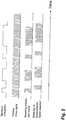
- Fig. 2it is considered to combine both modulation and pulsing to provide a signature to the emitted light. More specifically, there is illustrated in Fig. 2 a signature modulation that is combined to a pulsing drive signal, so as to produce a light signal combining both modulation and pulsing.
- This combination of pulsing and modulationis suitably used when a plurality of items are using the lighting system 10, so as to avoid interference between signals. For instance, if most cars are equipped with the object-detecting lighting system 10, the combination of modulation and pulsing is advantageously used.
- the visible-light source 12has in a preferred embodiment LEDs. More specifically, LEDs are well suited to be used in the lighting system 10 as LED intensity can be efficiently modulated/pulsed at high speed. Using this possibility, current lighting systems already installed for standard lighting applications can be used as the light source 12 for sensing applications.
- a detector 16is associated with the visible- light source 12.
- the detector 16is an optical detector (or detectors) provided so as to collect the light signal for instance reflected or diffused (i.e., backscattered) by the object A.
- the light signalcan also come from an object A being the direct source of this light (such as a remote control) in order to send information to the data/signal processor through the optical detector 16.
- the optical detector 16is as an example any of photodiodes, avalanche photodiodes (APD) or photomultipliers (PMT).
- Filtersare typically provided with the detector 16 to control ambient light background emitted from sources other than the lighting system 10. Filters can also be used for spectroscopic measurements and to enhance performance of the light source 12. For instance, there is illustrated in Fig. 3 a pulsed visible-light signal from a white LED filtered to blue as shown at L1 as compared with an unfiltered light signal shown at L2. In the case of white LEDs, the phosphor used converts the blue light of the LED junction into visible light with a certain time delay because of the phosphorescence emission lifetime.
- the blue part Ll' of the emission spectrum of white phosphorescent LEDsis preferably used, with proper wavelength filtering at detection, to allow faster light modulation, since the blue part Ll' will not suffer the phosphorescent material usual modulation speed reduction, as is illustrated in Fig. 4 by L2 ' . This would allow either faster modulation speed or light pulses while keeping the broadband illumination of the white LED for the scene illumination.
- a data/signal processor 18is connected to the detector 16, and receives detected light data therefrom.
- the data/signal processor 18is also connected to the source controller 14, so as to receive driving data therefrom.
- the data/signal processor 18has a processing unit (e.g., CPU) so as to interpret the detected light data from the detector 16, in comparison with the driving data of the source controller 14, which provides information about the predetermined mode of emission of the light signals emitted by the visible- light source 12.
- information about the objecte.g., presence, distance, speed of displacement, composition, dimension
- the data/signal processor 18is calculable by the data/signal processor 18 as a function of the relation (e.g., phase difference, relative intensity, spectral content, time of flight, etc.) between the driving data and the detected light data.
- a database 20may be provided in association with the data/signal processor 18 so as to provide historical data, or tabulated data to accelerate the calculation of the object parameters.
- the data/signal processor 18controls the source controller 14 and thus the light output of the visible-light source 12.
- the visible-light source 12may be required to increase or reduce its intensity, or change the parameters of its output.
- the data/signal processor 18may send the calculation output to an external system B in such a way that the external system B acts upon the information provided by the data/signal processor 18.
- the external system Bmay be the processing unit of a cruise-control system of a vehicle.
- the external system Bmay be a traffic-light central controlling unit.
- the external system Bcan also give input parameters to be used to the data/signal processor 18. These parameters can be adjustments to be performed to current calibration, new programs to be implemented for the current application, or data to be added to the database 20.
- the configuration of the detector 16 and of the data/signal processor 18is dependent on the application's requirements.
- One difficulty in many applicationsis to obtain an appropriate distance measurement when multiple objects are located at different positions within the fields of view of both the light source 12 and the optical detector 16. In such a case, each object in the field of view will contribute to the final distance value, weighed according to its real distance and reflectivity.
- One of the ways to get around this issueis to restrict the field of view of the detector (s), which limits the volume of space being probed.
- Sensor configurationsare arranged according to the specifications required from the application.
- an alternative embodiment of the sensor configurationinvolves a plurality of discrete detectors 16A to 16D, each observing a respective fixed field of view FOVA through FOVD within a volume of space illuminated by the light source 12 and comprising objects A1 through A4.
- Fields of view of the detectors 16A to 16Dare narrow or might be a combination of narrow and wide field of views as a trade-off between distance accuracy and number of detectors necessary.
- the optical detector 16is as an example any of photodiodes, APD or PMT. Such a configuration provides simplicity of design at the price of increased number of components and less intuitive integration.
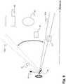
- FIG. 6Another alternative embodiment of the sensor configuration is depicted in Fig. 6 .
- the light source 12illuminates the same scene enclosing objects A1 through A4 , but only one discrete detector 16' having a narrow field of view FOV is used in combination with a scanning mechanism 50.
- the scanning mechanism 50changes the portion of the illuminated volume being probed by the detector, in essence changing the field of view FOV to FOV .
- detector 16'might be any of a photodiode, an APD, a PMT or equivalent thereof.
- This configurationminimizes the number of components but requires sequential probing of the illuminated volume and the use of a mobile part in the scanning mechanism 50.
- a motion of the scanning mechanism 50must be actuated by the data/signal processor 18 as the orientation of the scanning mechanism 50 will have an effect on the calculation of the position of the object.
- the light source 12 and illuminated sceneare similar to that of Fig. 6 (objects A1 through A4), but a detection array 16" is used with a large field of view FOVM encompassing the whole illuminated scene.
- Each pixel of the array 16"acts as a discrete detector with a very narrow field of view and probes a specific portion of the illuminated scene, as determined by any secondary optics in front of the array.
- the array 16"is any linear or 2D type array, such as APD or photodiode arrays , CCD and CMOS sensors.
- the light source 12is composed of multiple individual lighting elements 60 (e.g. LEDs or small clusters of LEDs) that are driven together by the illumination drive signal (without modulation), providing constant illumination of the scene.
- individual lighting elements 60e.g. LEDs or small clusters of LEDs
- each lighting element 60can be switched in turn from the illumination signal only to the modulated signal (or a combination of both illumination and modulation drive signals) required by the predetermined driving mode for a specific duration in a cycle.
- the modulated light elementillustrated by 60', illuminates only a portion of the scene with a narrow field of view FOVS, as determined by the appropriately designed secondary optics 61, while the other elements 60 are fed the illumination drive signal only, illuminating the rest of the scene without modulation.
- the secondary optics 61may take various forms (e.g., bulk, fiber) in accordance with the application.
- a discrete detector 16 with a large field of view FOVL encompassing the entire illuminated scenewill be sensitive only to objects within FOVS (for example, Object A3 in Fig. 8 ) .
- the discrete detector 16may be any of a photodiode, an APD, a PMT or equivalent thereof.
- This configurationis well adapted to applications where the light source 12 is or can be a group of lighting elements and simplifies the detection stage design, at the price of possible lower brightness of the modulated or pulsed source, more sophisticated design of the secondary source optics and sequential probing of the spatial volume of interest.
- the lighting system 10is particularly well suited for such applications.
- the automotive industryis looking for automated means to detect and measure the distance to cars and pedestrians around automobiles in order to automatically control the speed and brakes of the vehicles in collision avoidance systems and for adaptive cruise controls. These collisions are responsible for multiple deaths and injuries every year.
- the automotive industryis moving toward new technologies (e.g., collision avoidance systems, pedestrian safety systems, blind spot detection, occupant position detectors, etc) in order to decrease the number of fatalities related to collisions.
- One way of performing thisis to automatically detect obstacles along and beside the road with the lighting system 10 and to make the car or the driver react accordingly.
- cruise control systemsand other safety systems
- Such adaptive cruise controlcan be used to allow a car to automatically adapt its speed to a preceding car.
- LIDAR systemshave been described in the prior art as being used in cars.
- a laseris generally required for sufficient suppression of background sunlight or other cars' headlights.
- the laserhas to scan all around the car, or many lasers have to be used making this an expensive and complicated lighting device.
- the lighting system 10may use the headlights or signal lights based on LEDs (or other similar solid-state lighting devices) already present in cars as light source 12, whereby a large field of view would be covered without moving mechanical parts.
- the LEDs of the headlightscan be modulated or pulsed in order to get the capability to discriminate more easily against the background lights.
- the modulation frequencies usedcould then be swept (or shifted in time such as in optical-frequency-domain reflectometry) in order to allow discrimination of a large amount of cars lighting devices without possible interference.
- the method of signature modulation described above for Fig. 2could also be used.
- the amplitude modulation or pulsescan be used through known phase shift or time of flight measurements to get the distance between the car and other cars or objects (such as pedestrians) in the field of illumination of the headlights.
- Thiscoupled with adaptive cruise control, can be used to control the car's speed or brakes to avoid possible collisions at a lower cost and possibly with better efficiency and larger diffusion in all car market categories from low- to high-budget cars.
- all the already installed lighting systems around and in the car(such as brake, turn lights, or car ceiling lights) could be used in a similar manner to collect information on the presence and distance (up to 5 to 10m) of objects or individuals, by designing/retrofitting them into the lighting system 10, provided the light source 12 is suitable.
- detectorswork better at short range and with a limited field of view and, since many streetlights are placed on long posts, they would suffer many calibration problems for that application. Even if streetlights were to show characteristics allowing them to be adjusted in intensity on demand, this would probably be one reason why such detectors would not be placed on streetlights.
- An adapted detectorwould need to cover a large field of view, not being sensitive only to heat difference, but being sensitive enough inside the field of view to detect as well pedestrians than trucks. Finally, it would also need to be technologically available and integrated at low costs.
- Traffic lightsare another lighting application that is currently using LEDs as a light source.
- the increased irradiance, lifetime, switching time and efficiencyare beneficial to the application.
- an improvementwould be to add the features of the lighting system 10 to these lights by esigning/retrofitting the lights with the various components of the lighting system 10, rather than to use inductive or capacitive sensors placed at high cost into the ground under the road pavement.
- sensorsare placed under the pavement. Then, when a vehicle arrives at road crossings, it is detected (by electrical induction or capacitive sensing) and the traffic lights are activated with predetermined timing settings.
- electrical induction or capacitive sensingthe traffic lights are activated with predetermined timing settings.
- to place these sensors under the pavementrequires costly excavation work to be performed for each road crossing.
- the detectionoccurs only at the level of the sensors, so the speed and the number of cars cannot readily be estimated.
- the features of the lighting system 10would allow further intelligence to be implemented into the traffic light systems, and thus more possibility of lowering the risk of car accidents.
- an optical detectorto detect cars beneath or beside the lights, as proposed by the lighting system 10, would allow cheaper detection, since the pavement would not need to be removed to put the detector into place. Maintenance and repairs would also be less costly. Furthermore, using multiple detectors having different fields of view would allow detection of many vehicles at the same time and/or their speed, making it a useful tool for traffic measurement and control.
- the speed of the vehiclescould also be measured with the modulation phase shift measurement (or time of flight of pulsed light) technique described previously.
- the visibility changes in different weather conditionscould also be measured.
- the signaling yellow lights seen along roads in the vicinity of rivers to signal poor visibility conditions caused by fogcould be used as visible-light sources that would allow such visibility to be measured with proper detection.
- the lighting system 10could be used to detect an encoded light source placed on emergency vehicles (that could be the vehicle emergency lights themselves if based on LEDs) having a specific modulation scheme allowing to send a signal to the traffic lights to make them turn green in their favor.
- the optical detector 16 of the lighting system 10can be used to detect an encoded incoming light signal from external (or other) light sources such as a remote control that would allow communication in order to control, calibrate or configure the lighting unit for the current location and usage requirements.
- the measurement of vehicle speedis also possible either by distance measurement or by measurement of their time of passage at different points along the street lane beneath the LED street-lighting devices. This makes possible gathering of information that would not otherwise be possible, without installing special devices or sensors.
- the same type of possibilitycould be implemented, through the use of already installed lighting, allowing the detection of the presence of individuals or vehicles beneath the lights in order to control the light level accordingly. When no circulation is detected, the light level can be lowered to decrease the energy required.
- streetlights and traffic lights equipped with the detection capabilities provided by the lighting system 10could be the base of a network allowing to manage traffic and vehicle circulation inside cities and emergency situations having impacts on traffic. This could be made possible by putting their data/signal processing units 18 in communication with a central external traffic managing system (i.e., external system B) through RF links or through power lines.
- a central external traffic managing systemi.e., external system B
- the detectioncan include the presence and activity of individuals to control the light level accordingly or for surveillance to replace current movement detectors (e.g., in publicity, to flash an advertisement upon detection of the presence of a person), the detection of smog, the detection of hazardous gases .
- the LED lightingscan easily be modulated, in case of emergency situations, they can be made to blink so that people are more easily aware. The blinking sequence of different LED lightings located along an exit path can even be made to indicate the direction of the emergency exits.
- the lighting units of a buildingcan be made intelligent if they can communicate with each other through a local network.
- the networkcould be based on wireless communication links, on the light generated by one unit if it can reach other units, or on actual power lines.
- the communication between the lighting moduleswould allow them to be lit in a sequence along a path for people walking, for example, in a corridor.
- the communication capabilitiescan also be extended to the external system B being centralized in a house to record regular human activities and to adjust house heating, security level and comfort to these activities. Such information could also be used by centralized security system to check for possible emergency situations, such as people being inactive for more than 12 hours in a room.
- the lighting system 10includes interior and exterior lighting used in homes, farms, industrial buildings, commercial buildings, stadiums, etc.
Landscapes
- Physics & Mathematics (AREA)
- Engineering & Computer Science (AREA)
- General Physics & Mathematics (AREA)
- Computer Networks & Wireless Communication (AREA)
- Electromagnetism (AREA)
- Radar, Positioning & Navigation (AREA)
- Remote Sensing (AREA)
- Circuit Arrangement For Electric Light Sources In General (AREA)
- Measurement Of Optical Distance (AREA)
- Optical Radar Systems And Details Thereof (AREA)
- Geophysics And Detection Of Objects (AREA)
- Lighting Device Outwards From Vehicle And Optical Signal (AREA)
Description
- The present invention generally relates to lighting systems and more particularly to object- detection using visible light emitted by a lighting system.
- It has been known since the 1990' s that white light-emitting diodes (hereinafter "LEDs") can provide light that in some ways reproduces incandescent or fluorescent lighting systems with higher efficiency. These LEDs also emit light almost instantaneously (very fast turn on) and also stop emitting light almost instantaneously as well (very fast shut down response) . However, until recently these LEDs were not showing sufficient power output in a single unit to provide ambient lighting or to be part of lamps and luminaires. For a few years, LEDs have been a part of flashlights or small lighting devices that can be used for leisure or as security lighting requiring small electrical power consumption. LEDs have been used for decades as light sources in remote controls and sensors in different types of appliances, industrial applications, and home utilities.
- Nowadays, LEDs are developed by many manufacturers in order to make them a part of applications requiring powerful lighting such as headlamps in the automotive industry, lamps in household or industrial applications, and streetlights or luminaires. Advantages associated with LEDs include lower power consumption through an increased electrical to visible light conversion efficiency, longer lifetime, faster switching time, relative directivity of light coming out from them, and compactness allowing special designs to be developed. It is a question of a few years before LEDs will be part of powerful lighting systems replacing currently used incandescent and fluorescent lighting systems.
- Document
EP-A-1 334 869 concerns a beam radiator that radiates visible light beams having a predetermined wavelength onto a road surface to inform drivers of other vehicles of the existence of a self-owned vehicle or to let a driver of the self owned vehicle confirm a traveling path thereof is disposed in a front portion of a body of the self-owned vehicle. A vehicle operation supporting device comprises a beam radiating portion that radiates visible light beams onto a road surface according to a predetermined pattern, and an obstacle detecting portion that detects an obstacle that exists between a vehicle and a road surface onto which visible light beams are to be radiated. An optical filter is disposed substantially all over a windshield in front of a driver seat and is designed to have a characteristic of being more permeable to light having wavelengths close to a wavelength of visible light beams radiated from the beam radiator than to light having a wavelength different from those wavelengths. - Document
WO 2005/072358 concerns a red, green, blue, distance (RGB-Z) sensor, comprising a beam splitter such as a hot mirror, which receives and separates incoming first and second spectral band optical energy from a target object into preferably RGB image components and preferably NIR Z components. The RGB image and Z components are detected by respective RGB and NIR pixel detector array regions, which output respective image data and Z data. A display using the image data can be augmented with Z data to help recognize a target object. In case of motor vehicle headlights being high intensity LEDs, if such headlights include a modulated light component, the sensor can acquire Z data by sensing the modulated LED wavelength. In this case, Z data could be acquired from a pedestrian or other target object illuminated only by the LED headlights of a vehicle having the sensor, without the need to provide an additional second spectral band illumination source. - It is an object of the present invention to provide a novel object-detecting lighting system.
- It is a further object of the present invention to provide a novel method for detecting objects using visible light.
- Therefore, in accordance with the present invention, there is provided a method for detecting an object using visible light according to
claim 1. Claims 2-4 concern embodiments of the method for detecting an object using visible light. Further in accordance with the present invention, there is provided an object-detecting lighting system according to claim 5. Claims 6-10 concern embodiments of the object-detecting lighting system. - Having thus generally described the nature of the invention, reference will now be made to the accompanying drawings, showing by way of illustration a preferred embodiment thereof and in which:
Fig. 1 is a block diagram illustrating an object-detecting lighting system of the present invention;Fig. 2 is a schematic view illustrating a light signal of the object-detecting lighting system ofFig. 1 , resulting from a combination of a pulsing drive signal with signature modulation;Fig. 3 is a graph illustrating an amplitude of blue light over time as compared with unfiltered light from a high-brightness white LED;Fig. 4 is a graph illustrating an amplitude of blue light over time emitted by a high-brightness white LED as compared to light from a phosphor light emission isolated with another filter;Fig. 5 is a schematic view of an alternative sensor configuration for the object-detecting lighting system ofFig. 1 , with multiple detectors;Fig. 6 is a schematic view of an alternative sensor configuration for the object-detecting lighting system ofFig. 1 , with a scanning mechanism;Fig. 7 is a schematic view of an alternative sensor configuration for the object-detecting lighting system ofFig. 1 , using a detector array;- and
Fig. 8 is a schematic view of an alternative sensor configuration for the object-detecting lighting system ofFig. 1 , using a light source array. - Referring to
Fig. 1 , an object-detecting lighting system in accordance with a preferred embodiment of the present invention is generally shown at 10. - The
system 10 has a visible-light source 12. The visible-light source 12 has a first function the emission of visible light with enough intensity such that a user can collect information from its environment in a direct way (by seeing the light source 12) or indirect way (from scene illumination) through human vision, whether it be by illumination of the environment or emission of a signal. Examples of such lighting systems include lamps, illuminators, signs and displays, status indicators, amongst others. In a preferred embodiment, the visible-light source 12 has one or more LEDs, in accordance with the selected application of thesystem 10, a few of which are described hereinafter. As examples, the visible-light source 12 may be in the form of a home lighting fixture (e.g., lamp, illuminators), a traffic light, a street light system, a car headlight, taillight and/or brakelight, to only name a few applications. - The visible-
light source 12 is connected to asource controller 14, so as to be driven into producing light. In addition to emitting light, thesystem 10 performs detection of objects A (objects can include solids, airborne particles, gases and liquids, as long as the object provides enough reflected light to be detected) when these objects are part of the environment/scene illuminated by thelight source 12. Accordingly, thesource controller 14 drives the visible-light source 12 in a predetermined mode, such that the emitted light takes the form of a light signal, for instance by way of amplitude-modulated or pulsed light emission. - These light signals are such that they can be used to provide the lighting illumination level required by the application, through data/
signal processor 18 andsource controller 14, while providing the required lighting. This means a detectable signal is present. Accordingly, it is possible to obtain a light level equivalent to a continuous light source by modulating the light signal fast enough (e.g., more than 100Hz frequency) to be imperceptible to the eye and having an average light power equivalent to a continuous light source. - In an embodiment, the
source controller 14 is designed to provide an illumination drive signal, such as. a constant DC signal or a pulse-width modulated (PWM) signal, that is normally used in lighting systems to produce the required illumination and control its intensity. The illumination drive signal is produced by the illumination driver sub-module 14A of thecontroller 14. A modulated/pulsed driving signal supplies the fast modulation/pulse sequence required for remote object detection. This modulated/pulsed drive signal is produced by a modulation driver sub-module 14B of thecontroller 14. Both driving signals can be produced independently or in combination. Sequencing of the drive signal is controlled by the data/signal processor 18. - Referring to
Fig. 2 , it is considered to combine both modulation and pulsing to provide a signature to the emitted light. More specifically, there is illustrated inFig. 2 a signature modulation that is combined to a pulsing drive signal, so as to produce a light signal combining both modulation and pulsing. This combination of pulsing and modulation is suitably used when a plurality of items are using thelighting system 10, so as to avoid interference between signals. For instance, if most cars are equipped with the object-detectinglighting system 10, the combination of modulation and pulsing is advantageously used. - The visible-
light source 12 has in a preferred embodiment LEDs. More specifically, LEDs are well suited to be used in thelighting system 10 as LED intensity can be efficiently modulated/pulsed at high speed. Using this possibility, current lighting systems already installed for standard lighting applications can be used as thelight source 12 for sensing applications. - These applications range from presence detection for home lighting controls, to distance measurements between cars for adaptive cruise control, passing through fog or smoke detection, and going through spectroscopic measurements for gas emission or smog detection.
- A
detector 16 is associated with the visible-light source 12. Thedetector 16 is an optical detector (or detectors) provided so as to collect the light signal for instance reflected or diffused (i.e., backscattered) by the object A. The light signal can also come from an object A being the direct source of this light (such as a remote control) in order to send information to the data/signal processor through theoptical detector 16. Theoptical detector 16 is as an example any of photodiodes, avalanche photodiodes (APD) or photomultipliers (PMT). - Filters are typically provided with the
detector 16 to control ambient light background emitted from sources other than thelighting system 10. Filters can also be used for spectroscopic measurements and to enhance performance of thelight source 12. For instance, there is illustrated inFig. 3 a pulsed visible-light signal from a white LED filtered to blue as shown at L1 as compared with an unfiltered light signal shown at L2. In the case of white LEDs, the phosphor used converts the blue light of the LED junction into visible light with a certain time delay because of the phosphorescence emission lifetime. - In some applications, the blue part Ll' of the emission spectrum of white phosphorescent LEDs is preferably used, with proper wavelength filtering at detection, to allow faster light modulation, since the blue part Ll' will not suffer the phosphorescent material usual modulation speed reduction, as is illustrated in
Fig. 4 by L2 ' . This would allow either faster modulation speed or light pulses while keeping the broadband illumination of the white LED for the scene illumination. - A data/
signal processor 18 is connected to thedetector 16, and receives detected light data therefrom. The data/signal processor 18 is also connected to thesource controller 14, so as to receive driving data therefrom. The data/signal processor 18 has a processing unit (e.g., CPU) so as to interpret the detected light data from thedetector 16, in comparison with the driving data of thesource controller 14, which provides information about the predetermined mode of emission of the light signals emitted by the visible-light source 12. - Accordingly, information about the object (e.g., presence, distance, speed of displacement, composition, dimension) is calculable by the data/
signal processor 18 as a function of the relation (e.g., phase difference, relative intensity, spectral content, time of flight, etc.) between the driving data and the detected light data. Adatabase 20 may be provided in association with the data/signal processor 18 so as to provide historical data, or tabulated data to accelerate the calculation of the object parameters. - In view of the calculation it performs, the data/
signal processor 18 controls thesource controller 14 and thus the light output of the visible-light source 12. For instance, the visible-light source 12 may be required to increase or reduce its intensity, or change the parameters of its output. - Additionally, the data/
signal processor 18 may send the calculation output to an external system B in such a way that the external system B acts upon the information provided by the data/signal processor 18. For instance, the external system B may be the processing unit of a cruise-control system of a vehicle. As another non-exclusive example, the external system B may be a traffic-light central controlling unit. The external system B can also give input parameters to be used to the data/signal processor 18. These parameters can be adjustments to be performed to current calibration, new programs to be implemented for the current application, or data to be added to thedatabase 20. - The configuration of the
detector 16 and of the data/signal processor 18 is dependent on the application's requirements. One difficulty in many applications is to obtain an appropriate distance measurement when multiple objects are located at different positions within the fields of view of both thelight source 12 and theoptical detector 16. In such a case, each object in the field of view will contribute to the final distance value, weighed according to its real distance and reflectivity. One of the ways to get around this issue is to restrict the field of view of the detector (s), which limits the volume of space being probed. Sensor configurations are arranged according to the specifications required from the application. - Referring to
Fig. 5 , an alternative embodiment of the sensor configuration involves a plurality ofdiscrete detectors 16A to 16D, each observing a respective fixed field of view FOVA through FOVD within a volume of space illuminated by thelight source 12 and comprising objects A1 through A4. Fields of view of thedetectors 16A to 16D are narrow or might be a combination of narrow and wide field of views as a trade-off between distance accuracy and number of detectors necessary. Theoptical detector 16 is as an example any of photodiodes, APD or PMT. Such a configuration provides simplicity of design at the price of increased number of components and less intuitive integration. - Another alternative embodiment of the sensor configuration is depicted in
Fig. 6 . In this case, thelight source 12 illuminates the same scene enclosing objects A1 through A4 , but only one discrete detector 16' having a narrow field of view FOV is used in combination with ascanning mechanism 50. Thescanning mechanism 50 changes the portion of the illuminated volume being probed by the detector, in essence changing the field of view FOV to FOV . Again, detector 16' might be any of a photodiode, an APD, a PMT or equivalent thereof. This configuration minimizes the number of components but requires sequential probing of the illuminated volume and the use of a mobile part in thescanning mechanism 50. Moreover, a motion of thescanning mechanism 50 must be actuated by the data/signal processor 18 as the orientation of thescanning mechanism 50 will have an effect on the calculation of the position of the object. - In another alternative embodiment of the sensor configuration illustrated by
Fig. 7 , thelight source 12 and illuminated scene are similar to that ofFig. 6 (objects A1 through A4), but adetection array 16" is used with a large field of view FOVM encompassing the whole illuminated scene. Each pixel of thearray 16" acts as a discrete detector with a very narrow field of view and probes a specific portion of the illuminated scene, as determined by any secondary optics in front of the array. Thearray 16" is any linear or 2D type array, such as APD or photodiode arrays , CCD and CMOS sensors. - Another alternative embodiment presented in
Fig. 8 transfers to the source side the need to select a field of view of detection from within the field of view of illumination. In this embodiment, thelight source 12 is composed of multiple individual lighting elements 60 (e.g. LEDs or small clusters of LEDs) that are driven together by the illumination drive signal (without modulation), providing constant illumination of the scene. - Using a sequencing component within the
source controller 14, eachlighting element 60 can be switched in turn from the illumination signal only to the modulated signal (or a combination of both illumination and modulation drive signals) required by the predetermined driving mode for a specific duration in a cycle. The modulated light element, illustrated by 60', illuminates only a portion of the scene with a narrow field of view FOVS, as determined by the appropriately designedsecondary optics 61, while theother elements 60 are fed the illumination drive signal only, illuminating the rest of the scene without modulation. Thesecondary optics 61 may take various forms (e.g., bulk, fiber) in accordance with the application. - After the specified duration, another
element 60 is switched to modulated mode and the initial element 60' falls back to the illumination drive signal only. This operation is repeated according to programming of the data/signal processor 18, which controls drive sequencing (as shown inFig. 1 ) . In essence, the modulated or pulsed light emission is being scanned in discrete steps in the illuminated spatial volume. - In such a configuration, a
discrete detector 16 with a large field of view FOVL encompassing the entire illuminated scene will be sensitive only to objects within FOVS (for example, Object A3 inFig. 8 ) . Again, thediscrete detector 16 may be any of a photodiode, an APD, a PMT or equivalent thereof. This configuration is well adapted to applications where thelight source 12 is or can be a group of lighting elements and simplifies the detection stage design, at the price of possible lower brightness of the modulated or pulsed source, more sophisticated design of the secondary source optics and sequential probing of the spatial volume of interest. - Solutions are sought in the fields of the automotive industry and urban power management efficiency, and the
lighting system 10 is particularly well suited for such applications. For example, the automotive industry is looking for automated means to detect and measure the distance to cars and pedestrians around automobiles in order to automatically control the speed and brakes of the vehicles in collision avoidance systems and for adaptive cruise controls. These collisions are responsible for multiple deaths and injuries every year. - The automotive industry is moving toward new technologies (e.g., collision avoidance systems, pedestrian safety systems, blind spot detection, occupant position detectors, etc) in order to decrease the number of fatalities related to collisions. One way of performing this is to automatically detect obstacles along and beside the road with the
lighting system 10 and to make the car or the driver react accordingly. - For example, it is contemplated to link cruise control systems (and other safety systems) as the external system B associated with the
lighting system 10. Such adaptive cruise control can be used to allow a car to automatically adapt its speed to a preceding car. - LIDAR systems have been described in the prior art as being used in cars. In such applications, a laser is generally required for sufficient suppression of background sunlight or other cars' headlights. Furthermore, in order to cover a large field of view allowing the driving lane and also the lanes on each side to be seen, the laser has to scan all around the car, or many lasers have to be used making this an expensive and complicated lighting device.
- On the other hand, the
lighting system 10 may use the headlights or signal lights based on LEDs (or other similar solid-state lighting devices) already present in cars aslight source 12, whereby a large field of view would be covered without moving mechanical parts. The LEDs of the headlights can be modulated or pulsed in order to get the capability to discriminate more easily against the background lights. As the background lights of other vehicles could be equipped with thelighting system 10 as well, the modulation frequencies used could then be swept (or shifted in time such as in optical-frequency-domain reflectometry) in order to allow discrimination of a large amount of cars lighting devices without possible interference. Alternatively, the method of signature modulation described above forFig. 2 could also be used. - Furthermore, the amplitude modulation or pulses can be used through known phase shift or time of flight measurements to get the distance between the car and other cars or objects (such as pedestrians) in the field of illumination of the headlights. This, coupled with adaptive cruise control, can be used to control the car's speed or brakes to avoid possible collisions at a lower cost and possibly with better efficiency and larger diffusion in all car market categories from low- to high-budget cars. In fact, all the already installed lighting systems around and in the car (such as brake, turn lights, or car ceiling lights) could be used in a similar manner to collect information on the presence and distance (up to 5 to 10m) of objects or individuals, by designing/retrofitting them into the
lighting system 10, provided thelight source 12 is suitable. The visibility in bad weather could also be estimated through light-diffusion measurements on snow, fog, dust or rain. Police or governmental vehicles could even be equipped with more capable detection systems to detect cars with bad gas emissions causing pollution problems. Other applications considered include parking assistance, blind-spot detector. - Energy consumption is an increasing concern because of the rising costs of energy. Efficient street lighting power consumption, and thus energy budgets of cities, will benefit from LEDs when they reach this application. Controlling the light level is readily achieved with LEDs compared to current sodium luminaires which have a restrike time in the order of minutes. Thus, with LEDs it becomes feasible to control streetlight level when no civilians are circulating under these lights, and this also allows energy savings.
- Current street-lighting systems do not allow the adjustment of light level on demand which would readily be performed using the
lighting system 10. Such adjustment capability would allow a decrease in their energy consumption. For example, sodium lights can hardly be adjusted in intensity. Usually, no detection systems are present, or they are based on movement detection sensors, which are usually based on infrared detectors that can hardly detect moving people or vehicles at hot ambient temperatures or people covered in winter clothes in cold weather. - Furthermore, such detectors work better at short range and with a limited field of view and, since many streetlights are placed on long posts, they would suffer many calibration problems for that application. Even if streetlights were to show characteristics allowing them to be adjusted in intensity on demand, this would probably be one reason why such detectors would not be placed on streetlights. An adapted detector would need to cover a large field of view, not being sensitive only to heat difference, but being sensitive enough inside the field of view to detect as well pedestrians than trucks. Finally, it would also need to be technologically available and integrated at low costs.
- Traffic lights are another lighting application that is currently using LEDs as a light source. In this case, the increased irradiance, lifetime, switching time and efficiency are beneficial to the application. In this latter case, an improvement would be to add the features of the
lighting system 10 to these lights by esigning/retrofitting the lights with the various components of thelighting system 10, rather than to use inductive or capacitive sensors placed at high cost into the ground under the road pavement. - In the case of prior art traffic lights with detection capabilities, sensors are placed under the pavement. Then, when a vehicle arrives at road crossings, it is detected (by electrical induction or capacitive sensing) and the traffic lights are activated with predetermined timing settings. However, to place these sensors under the pavement requires costly excavation work to be performed for each road crossing.
- With such sensors, the detection occurs only at the level of the sensors, so the speed and the number of cars cannot readily be estimated. The features of the
lighting system 10 would allow further intelligence to be implemented into the traffic light systems, and thus more possibility of lowering the risk of car accidents. - Using an optical detector to detect cars beneath or beside the lights, as proposed by the
lighting system 10, would allow cheaper detection, since the pavement would not need to be removed to put the detector into place. Maintenance and repairs would also be less costly. Furthermore, using multiple detectors having different fields of view would allow detection of many vehicles at the same time and/or their speed, making it a useful tool for traffic measurement and control. - The speed of the vehicles could also be measured with the modulation phase shift measurement (or time of flight of pulsed light) technique described previously. Here again, the visibility changes in different weather conditions could also be measured. In fact, the signaling yellow lights seen along roads in the vicinity of rivers to signal poor visibility conditions caused by fog could be used as visible-light sources that would allow such visibility to be measured with proper detection. The
lighting system 10 could be used to detect an encoded light source placed on emergency vehicles (that could be the vehicle emergency lights themselves if based on LEDs) having a specific modulation scheme allowing to send a signal to the traffic lights to make them turn green in their favor. Theoptical detector 16 of thelighting system 10 can be used to detect an encoded incoming light signal from external (or other) light sources such as a remote control that would allow communication in order to control, calibrate or configure the lighting unit for the current location and usage requirements. - The measurement of vehicle speed is also possible either by distance measurement or by measurement of their time of passage at different points along the street lane beneath the LED street-lighting devices. This makes possible gathering of information that would not otherwise be possible, without installing special devices or sensors.
- It is even possible to envision the possibility of implementing spectroscopic detection at two (or more) different wavelengths of gas emission from vehicles or other sources in the vicinity of the streetlights (for homeland security issues) . The different wavelengths would then allow detection (with two detectors detecting different wavelengths) of a difference in signals from either different absorption or diffusion levels from gases. Here again, the visibility changes in different weather conditions could also be measured.
- For luminaires or streetlights based on LEDs, the same type of possibility could be implemented, through the use of already installed lighting, allowing the detection of the presence of individuals or vehicles beneath the lights in order to control the light level accordingly. When no circulation is detected, the light level can be lowered to decrease the energy required.
- In fact, streetlights and traffic lights equipped with the detection capabilities provided by the
lighting system 10 could be the base of a network allowing to manage traffic and vehicle circulation inside cities and emergency situations having impacts on traffic. This could be made possible by putting their data/signal processing units 18 in communication with a central external traffic managing system (i.e., external system B) through RF links or through power lines. - In the case of lights used inside and outside houses and offices, two things need to be considered. The possibility of adjusting their intensity would allow better energy usage, while detection capabilities would allow adjustment of light intensity related to room usage and surveillance sensing for security systems. Current lighting systems used in and outside homes do not provide automatic adjustment of light level, or, if they do, they usually use IR movement detectors that are integrated apart from the light enclosure itself, or they are not based on the detection of the actual lighting itself. This results in higher production and installation costs.
- In interior applications, the detection can include the presence and activity of individuals to control the light level accordingly or for surveillance to replace current movement detectors (e.g., in publicity, to flash an advertisement upon detection of the presence of a person), the detection of smog, the detection of hazardous gases . Since the LED lightings can easily be modulated, in case of emergency situations, they can be made to blink so that people are more easily aware. The blinking sequence of different LED lightings located along an exit path can even be made to indicate the direction of the emergency exits.
- In fact, the lighting units of a building can be made intelligent if they can communicate with each other through a local network. The network could be based on wireless communication links, on the light generated by one unit if it can reach other units, or on actual power lines. The communication between the lighting modules would allow them to be lit in a sequence along a path for people walking, for example, in a corridor. The communication capabilities can also be extended to the external system B being centralized in a house to record regular human activities and to adjust house heating, security level and comfort to these activities. Such information could also be used by centralized security system to check for possible emergency situations, such as people being inactive for more than 12 hours in a room.
- There are numerous other applications for the
lighting system 10. This includes interior and exterior lighting used in homes, farms, industrial buildings, commercial buildings, stadiums, etc.
Claims (10)
- A method for detecting an object (A) using visible light, comprising:providing a visible-light source (12) in the form of one or more white light-emitting diodes adapted to emit visible light having a first function of being visible to a person in an illumination mode;connecting a source controller (14) to the visible-light source (12);actuating the visible-light source (12) to emit visible light in the illumination mode to illuminate an environment,characterized in that the one or more white light-emitting diodes are one or more white phosphorescent light-emitting diodes and it further comprises :driving the one or more white phosphorescent light-emitting diodes with the source controller (14) to emit visible light in a predetermined mode, the emitted visible light comprising a detectable signal, with visible light in the predetermined mode being emitted such that the one or more white phosphorescent light-emitting diodes maintains said first function of being visible to an unaided human eye while being driven by the source controller (14); said driving comprising combining both modulation and pulsing to provide a signature modulation to the emitted light, wherein the modulation is carried out a frequency exceeding 100 Hz,receiving a reflection or backscatter of the emitted visible light from an object (A), wherein said receiving the reflection or backscatter comprises filtering the reflection or backscatter to blue ; andcalculating a distance of the object (A) as a function of the reflection or backscatter received and of the predetermined mode.
- The method according to claim 1, wherein the first function is at least one of illuminating an environment of the one or more white phosphorescent light-emitting diodes and emitting a signal to a person in the environment.
- The method according to claim 3, wherein the step of calculating a distance of the object is performed by measuring a time delay between emitting the visible light and receiving the reflection or backscatter from the object.
- The method according to claim 1, further comprising a step of triggering an action as a function of the position of the object.
- An object-detecting lighting system (10) comprising:a light source (12) emitting visible light and having a first function of emitting visible light in an illumination mode for at least one of illuminating an environment and emitting a signal to a person in the environment;a source controller (14) for driving the light source (12) into emitting the visible light in a predetermined mode, with visible light comprising a detectable signal, with visible light in the predetermined mode being emitted such that the light source (12) maintains said first function of illuminating an environment or emitting a signal visible to an unaided human eye in the environment while being driven by the source controller (14);said object-detecting lighting system (10) beingcharacterized in that
the light source (12) is provided in the form of one or more white phosphorescent light-emitting diodes,
the source controller (14) is designed to combine both modulation and pulsing to provide a signature modulation to the emitted light, wherein the modulation is carried out a frequency exceeding 100Hz, andin that it further comprises :an optical detector (16) positioned with respect to the one or more white phosphorescent light-emitting diodes and adapted to detect the visible light as reflected or backscattered by an object (A), wherein the optical detector (16) has a filtering device to filter the reflected or backscattered visible light to blue; anda data or signal processor (18) for receiving detection data from the optical detector, the data or signal processor calculating the distance of the object as a function of the predetermined mode and the detection data. - The object-detecting lighting system (10) according to claim 5, wherein the optical detector (16) has a plurality of sub-detectors (16A, 16B, 16C, 16D) each detecting a narrow range, with each sub-detector (16A, 16B, 16C, 16D) combining to cover a wide range of emitted light of the one or more white phosphorescent light-emitting diodes.
- The object-detecting lighting system (10) according to claim 5, further comprising a scanning mechanism (50) in association with the optical detector (16') so as to cause a scanning motion of a field of view of the optical detector (16') within a range of illumination of emitted light of the one or more white phosphorescent light-emitting diodes.
- The object-detecting lighting system (10) according to claim 5, wherein the optical detector (16) has an array of sub-detectors (16").
- The object-detecting lighting system (10) according to claim 5, wherein the source controller (14) has a pulse or modulation driver (14B) to drive the one or more white phosphorescent light-emitting diodes into emitting visible-light in the predetermined mode, and an illumination driver (14A) to drive the one or more white phosphorescent light-emitting diodesinto emitting visible-light of suitable intensity to illuminate an environment.
- The object-detecting lighting system (10) according to claim 9, wherein the one or more white phosphorescent light-emitting diodes has a plurality of white phosphorescent light-emitting diodes, with at least one of the white phosphorescent light-emitting diodes (60) being driven by the illumination driver to illuminate the environment, while at least another one of the white phosphorescent light-emitting diodes (60') is driven by the pulse or modulation driver to emit the visible light in the predetermined mode.
Applications Claiming Priority (2)
| Application Number | Priority Date | Filing Date | Title |
|---|---|---|---|
| US75128405P | 2005-12-19 | 2005-12-19 | |
| PCT/CA2006/002067WO2007071032A1 (en) | 2005-12-19 | 2006-12-19 | Object-detecting lighting system and method |
Publications (3)
| Publication Number | Publication Date |
|---|---|
| EP1969395A1 EP1969395A1 (en) | 2008-09-17 |
| EP1969395A4 EP1969395A4 (en) | 2010-09-08 |
| EP1969395B1true EP1969395B1 (en) | 2017-08-09 |
Family
ID=38188213
Family Applications (1)
| Application Number | Title | Priority Date | Filing Date |
|---|---|---|---|
| EP06840494.6AActiveEP1969395B1 (en) | 2005-12-19 | 2006-12-19 | Object-detecting lighting system and method |
Country Status (6)
| Country | Link |
|---|---|
| US (1) | US7855376B2 (en) |
| EP (1) | EP1969395B1 (en) |
| JP (2) | JP2009520194A (en) |
| CN (1) | CN101356450B (en) |
| CA (1) | CA2633377C (en) |
| WO (1) | WO2007071032A1 (en) |
Cited By (1)
| Publication number | Priority date | Publication date | Assignee | Title |
|---|---|---|---|---|
| WO2021078511A1 (en) | 2019-10-22 | 2021-04-29 | Valeo Schalter Und Sensoren Gmbh | Method for detecting objects in a monitored region using an optical detection apparatus, and optical detection apparatus |
Families Citing this family (159)
| Publication number | Priority date | Publication date | Assignee | Title |
|---|---|---|---|---|
| WO2008154736A1 (en)* | 2007-06-18 | 2008-12-24 | Leddartech Inc. | Lighting system with driver assistance capabilities |
| EP1969395B1 (en)* | 2005-12-19 | 2017-08-09 | Leddartech Inc. | Object-detecting lighting system and method |
| US8242476B2 (en) | 2005-12-19 | 2012-08-14 | Leddartech Inc. | LED object detection system and method combining complete reflection traces from individual narrow field-of-view channels |
| DE102007013299A1 (en)* | 2007-03-06 | 2008-09-11 | Cedes Ag | Sensor device and system with a conveyor and a sensor device |
| US8767215B2 (en) | 2007-06-18 | 2014-07-01 | Leddartech Inc. | Method for detecting objects with light |
| US8319949B2 (en)* | 2007-06-18 | 2012-11-27 | Leddartech Inc. | Method for detecting objects with visible light |
| EP2158579B1 (en) | 2007-06-18 | 2014-10-15 | Leddartech Inc. | Lighting system with traffic management capabilities |
| DE102007049618A1 (en)* | 2007-10-17 | 2009-04-23 | Audi Ag | Device and method for determining an operating parameter of at least one light source of a light source of a motor vehicle |
| DE102007053138A1 (en)* | 2007-11-08 | 2009-01-29 | Adc Automotive Distance Control Systems Gmbh | Relevant surrounding object e.g. pedestrian, displaying device for vehicle, has controller connected with sensor system for surrounding detection over uni-directional data exchange device |
| EP2235561B8 (en) | 2007-12-21 | 2017-05-31 | Leddartech Inc. | Detection and ranging methods and systems |
| US8723689B2 (en)* | 2007-12-21 | 2014-05-13 | Leddartech Inc. | Parking management system and method using lighting system |
| NL1035051C2 (en) | 2008-02-20 | 2009-08-24 | Markus Henricus Beuvink | Method, system and optical communication composition for obtaining traffic information. |
| US7667855B2 (en)* | 2008-02-29 | 2010-02-23 | International Business Machines Corporation | Providing position information to computing equipment installed in racks of a datacenter |
| RU2383032C1 (en)* | 2008-06-02 | 2010-02-27 | Валерий Георгиевич Бондарев | Method of measuring coordinates of flickering point on earth's surface and device for realising said method |
| WO2010093391A1 (en)* | 2009-02-10 | 2010-08-19 | Consolidated Edison Company Of New York, Inc. | Optical reading system and method of operation |
| WO2010093389A1 (en)* | 2009-02-10 | 2010-08-19 | Consolidated Edison Company Of New York, Inc. | Optical reading system |
| WO2010093390A1 (en)* | 2009-02-10 | 2010-08-19 | Consolidated Edison Company Of New York, Inc. | Remote monitoring system |
| CN101825697B (en)* | 2009-03-06 | 2013-01-23 | 财团法人工业技术研究院 | Positioning method and system based on light intensity |
| US9405000B2 (en) | 2009-03-06 | 2016-08-02 | Industrial Technology Research Institute | Positioning method and positioning system based on light intensity |
| US8587222B2 (en)* | 2009-04-15 | 2013-11-19 | Empire Technology Development Llc | Energy saver for area lights |
| US9800017B1 (en) | 2009-05-29 | 2017-10-24 | Soraa Laser Diode, Inc. | Laser device and method for a vehicle |
| DE102010025114B4 (en)* | 2009-07-23 | 2014-08-07 | Leica Instruments (Singapore) Pte. Ltd. | Microscope with a microscope body and a tripod made of several components to fulfill a carrying function or a positioning of the microscope in space |
| ITMO20090210A1 (en)* | 2009-08-07 | 2011-02-08 | Zetech S R L | ROAD SIGNALING SYSTEM |
| PL2306425T3 (en)* | 2009-10-01 | 2011-12-30 | Kapsch Trafficcom Ag | Device and method for detecting wheel axles |
| PT2306428E (en)* | 2009-10-01 | 2012-02-06 | Kapsch Trafficcom Ag | Device and method for determining the direction, speed and/or distance of vehicles |
| FR2953602B1 (en)* | 2009-12-04 | 2012-07-27 | Valeo Vision | OBSTACLE DETECTION SYSTEM FOR VEHICLE |
| US20120218107A1 (en)* | 2009-12-14 | 2012-08-30 | Yvan Mimeault | Entity detection system and method for monitoring an area |
| CN102959599B (en) | 2009-12-22 | 2015-07-15 | 莱达科技股份有限公司 | Active 3D monitoring system for traffic detection |
| US9179106B2 (en)* | 2009-12-28 | 2015-11-03 | Canon Kabushiki Kaisha | Measurement system, image correction method, and computer program |
| DE102010001113B4 (en) | 2010-01-21 | 2023-02-16 | pmdtechnologies ag | Illumination for a time-of-flight camera |
| US8891067B2 (en)* | 2010-02-01 | 2014-11-18 | Microsoft Corporation | Multiple synchronized optical sources for time-of-flight range finding systems |
| JP4918732B2 (en)* | 2010-03-05 | 2012-04-18 | 日本電気株式会社 | Light measuring apparatus and method |
| DE102010026564B4 (en)* | 2010-07-08 | 2024-08-29 | HELLA GmbH & Co. KGaA | Method for detecting visibility conditions outside a motor vehicle |
| US8743023B2 (en) | 2010-07-23 | 2014-06-03 | Biological Illumination, Llc | System for generating non-homogenous biologically-adjusted light and associated methods |
| CA2802487C (en) | 2010-07-23 | 2016-06-28 | Leddartech Inc. | 3d optical detection system and method for a mobile storage system |
| US9681522B2 (en) | 2012-05-06 | 2017-06-13 | Lighting Science Group Corporation | Adaptive light system and associated methods |
| US8841864B2 (en) | 2011-12-05 | 2014-09-23 | Biological Illumination, Llc | Tunable LED lamp for producing biologically-adjusted light |
| US8686641B2 (en) | 2011-12-05 | 2014-04-01 | Biological Illumination, Llc | Tunable LED lamp for producing biologically-adjusted light |
| US9827439B2 (en) | 2010-07-23 | 2017-11-28 | Biological Illumination, Llc | System for dynamically adjusting circadian rhythm responsive to scheduled events and associated methods |
| US8760370B2 (en) | 2011-05-15 | 2014-06-24 | Lighting Science Group Corporation | System for generating non-homogenous light and associated methods |
| US9024536B2 (en) | 2011-12-05 | 2015-05-05 | Biological Illumination, Llc | Tunable LED lamp for producing biologically-adjusted light and associated methods |
| US9532423B2 (en) | 2010-07-23 | 2016-12-27 | Lighting Science Group Corporation | System and methods for operating a lighting device |
| TW201208477A (en)* | 2010-08-02 | 2012-02-16 | Hon Hai Prec Ind Co Ltd | Smart street lamp controlling system and the controlling method thereof |
| US8401231B2 (en) | 2010-11-09 | 2013-03-19 | Biological Illumination, Llc | Sustainable outdoor lighting system for use in environmentally photo-sensitive area |
| CN101995576A (en)* | 2010-11-12 | 2011-03-30 | 中国神华能源股份有限公司 | Vehicle position determining system |
| CN102162832A (en)* | 2010-12-23 | 2011-08-24 | 江苏兆伏新能源有限公司 | Method and system for detecting solar cell panel array faults |
| DE102011010334B4 (en)* | 2011-02-04 | 2014-08-28 | Eads Deutschland Gmbh | Camera system and method for observing objects at a great distance, in particular for monitoring target objects at night, mist, dust or rain |
| EP2498583B1 (en)* | 2011-03-07 | 2017-05-03 | Zedel | LED lamp provided with a safety device |
| TWI430066B (en)* | 2011-03-16 | 2014-03-11 | Young Lighting Technology Corp | Lighting device and method for adjusting sensing region thereof |
| US8384984B2 (en) | 2011-03-28 | 2013-02-26 | Lighting Science Group Corporation | MEMS wavelength converting lighting device and associated methods |
| US8908159B2 (en) | 2011-05-11 | 2014-12-09 | Leddartech Inc. | Multiple-field-of-view scannerless optical rangefinder in high ambient background light |
| US9173269B2 (en) | 2011-05-15 | 2015-10-27 | Lighting Science Group Corporation | Lighting system for accentuating regions of a layer and associated methods |
| US8901850B2 (en) | 2012-05-06 | 2014-12-02 | Lighting Science Group Corporation | Adaptive anti-glare light system and associated methods |
| US8754832B2 (en) | 2011-05-15 | 2014-06-17 | Lighting Science Group Corporation | Lighting system for accenting regions of a layer and associated methods |
| EP2721593B1 (en) | 2011-06-17 | 2017-04-05 | Leddartech Inc. | System and method for traffic side detection and characterization |
| US8515289B2 (en) | 2011-11-21 | 2013-08-20 | Environmental Light Technologies Corp. | Wavelength sensing lighting system and associated methods for national security application |
| US8866414B2 (en) | 2011-12-05 | 2014-10-21 | Biological Illumination, Llc | Tunable LED lamp for producing biologically-adjusted light |
| US9913341B2 (en) | 2011-12-05 | 2018-03-06 | Biological Illumination, Llc | LED lamp for producing biologically-adjusted light including a cyan LED |
| US9289574B2 (en) | 2011-12-05 | 2016-03-22 | Biological Illumination, Llc | Three-channel tuned LED lamp for producing biologically-adjusted light |
| US9220202B2 (en) | 2011-12-05 | 2015-12-29 | Biological Illumination, Llc | Lighting system to control the circadian rhythm of agricultural products and associated methods |
| US8963450B2 (en) | 2011-12-05 | 2015-02-24 | Biological Illumination, Llc | Adaptable biologically-adjusted indirect lighting device and associated methods |
| JP6190381B2 (en)* | 2011-12-08 | 2017-08-30 | フィリップス ライティング ホールディング ビー ヴィ | lighting equipment |
| DE102012002922A1 (en)* | 2012-02-14 | 2013-08-14 | Audi Ag | Time-of-flight camera for a motor vehicle, motor vehicle and method for operating a time-of-flight camera |
| JP2013167559A (en)* | 2012-02-16 | 2013-08-29 | Mitsuru Sato | Illumination device with localization mechanism, and localization system |
| CA2865733C (en) | 2012-03-02 | 2023-09-26 | Leddartech Inc. | System and method for multipurpose traffic detection and characterization |
| JP5916443B2 (en)* | 2012-03-08 | 2016-05-11 | 株式会社トプコン | Light wave distance meter |
| CN102625546A (en)* | 2012-04-18 | 2012-08-01 | 张家炎 | Automatic dimming constant light control system |
| CN102665333A (en)* | 2012-04-19 | 2012-09-12 | 广东工业大学 | Light source system self-adapting according to size and brightness of space |
| BR112014026016A8 (en)* | 2012-04-20 | 2021-03-09 | Rensselaer Polytech Inst | sensory lighting system and method to characterize a lighting space |
| US9402294B2 (en) | 2012-05-08 | 2016-07-26 | Lighting Science Group Corporation | Self-calibrating multi-directional security luminaire and associated methods |
| US9006987B2 (en) | 2012-05-07 | 2015-04-14 | Lighting Science Group, Inc. | Wall-mountable luminaire and associated systems and methods |
| US8680457B2 (en) | 2012-05-07 | 2014-03-25 | Lighting Science Group Corporation | Motion detection system and associated methods having at least one LED of second set of LEDs to vary its voltage |
| EP2703836B1 (en) | 2012-08-30 | 2015-06-24 | Softkinetic Sensors N.V. | TOF illuminating system and TOF camera and method for operating, with control means for driving electronic devices located in the scene |
| US9174067B2 (en) | 2012-10-15 | 2015-11-03 | Biological Illumination, Llc | System for treating light treatable conditions and associated methods |
| CN103808981B (en)* | 2012-11-13 | 2016-12-21 | 昆山西钛微电子科技有限公司 | There is the image sensor dice test fixture of testing light source |
| US9347655B2 (en) | 2013-03-11 | 2016-05-24 | Lighting Science Group Corporation | Rotatable lighting device |
| DE102013102608A1 (en) | 2013-03-14 | 2014-09-18 | Audi Ag | Collision protection device for a hinged flap of a motor vehicle, flap, motor vehicle and corresponding method |
| US20140268731A1 (en) | 2013-03-15 | 2014-09-18 | Lighting Science Group Corpporation | Low bay lighting system and associated methods |
| DE102013104274A1 (en)* | 2013-04-26 | 2014-10-30 | Hella Kgaa Hueck & Co. | Method for the determination of the proportion of own light in reflected light |
| AT514218B1 (en)* | 2013-05-06 | 2015-05-15 | Bluetechnix Gmbh | vehicle headlights |
| ITRM20130274A1 (en)* | 2013-05-08 | 2014-11-09 | Smart I S R L | DISTRIBUTED AND INTELLIGENT OPTICAL SENSOR SYSTEM FOR ADAPTIVE, PREDICTIVE AND ON-DEMAND CONTROL OF PUBLIC LIGHTING |
| CN104344248A (en)* | 2013-08-05 | 2015-02-11 | 上海广茂达光艺科技股份有限公司 | Intelligent light-mixing system and method |
| EP3036132B1 (en)* | 2013-08-19 | 2019-02-27 | Gentex Corporation | Vehicle imaging system and method for distinguishing reflective objects from lights of another vehicle |
| WO2015025497A1 (en) | 2013-08-23 | 2015-02-26 | パナソニックIpマネジメント株式会社 | Distance measurement system and signal generation device |
| CN104470045B (en)* | 2013-09-23 | 2018-10-26 | 深圳市海洋王照明工程有限公司 | A kind of ranging flashlight circuit and device |
| CN104470043B (en)* | 2013-09-23 | 2019-05-03 | 深圳市海洋王照明工程有限公司 | A kind of flashlight circuit for ranging |
| US8960954B1 (en) | 2013-10-08 | 2015-02-24 | Geoffrey Farrell | Sea turtle light control system and method |
| JP6371158B2 (en)* | 2013-11-14 | 2018-08-08 | ルネサスエレクトロニクス株式会社 | LED lamp, projector, data processing method, and collision prevention apparatus |
| US9420674B2 (en) | 2013-11-21 | 2016-08-16 | General Electric Company | System and method for monitoring street lighting luminaires |
| US10509101B2 (en) | 2013-11-21 | 2019-12-17 | General Electric Company | Street lighting communications, control, and special services |
| US9646495B2 (en) | 2013-11-21 | 2017-05-09 | General Electric Company | Method and system for traffic flow reporting, forecasting, and planning |
| US9621265B2 (en) | 2013-11-21 | 2017-04-11 | General Electric Company | Street lighting control, monitoring, and data transportation system and method |
| US9622323B2 (en) | 2013-11-21 | 2017-04-11 | General Electric Company | Luminaire associate |
| CN103675830A (en)* | 2013-12-09 | 2014-03-26 | 苏州市峰之火数码科技有限公司 | Outdoor distance measurement glasses |
| JP6359828B2 (en)* | 2013-12-20 | 2018-07-18 | 株式会社メガチップス | Lighting system and control device |
| WO2015128192A1 (en) | 2014-02-26 | 2015-09-03 | Koninklijke Philips N.V. | Light reflectance based detection |
| US11143749B2 (en) | 2014-05-23 | 2021-10-12 | Signify Holding B.V. | Object detection system and method |
| US9671495B2 (en) | 2014-06-11 | 2017-06-06 | Intersil Americas LLC | Systems and methods for optical proximity detection with multiple field of views |
| US9753351B2 (en)* | 2014-06-30 | 2017-09-05 | Quanergy Systems, Inc. | Planar beam forming and steering optical phased array chip and method of using same |
| JP6606549B2 (en)* | 2014-08-08 | 2019-11-13 | パーセプティメッド インコーポレイテッド | Tablet speed and position sensor |
| JP6938371B2 (en) | 2014-09-09 | 2021-09-22 | レッダーテック インコーポレイテッド | Discretization of detection zones |
| FR3027654B1 (en) | 2014-10-24 | 2019-08-02 | Valeo Vision | LIGHTING AND / OR SIGNALING SYSTEM COMPRISING TELEMETRY MEANS |
| US9433065B2 (en)* | 2014-11-05 | 2016-08-30 | Stmicroelectronics (Research & Development) Limited | Lighting system including time of flight ranging system |
| US10114112B2 (en) | 2015-03-26 | 2018-10-30 | Qualcomm Incorporated | Communicating service information from one light detection and ranging (LIDAR) system to another LIDAR system |
| US10834065B1 (en) | 2015-03-31 | 2020-11-10 | F5 Networks, Inc. | Methods for SSL protected NTLM re-authentication and devices thereof |
| DE102015104965A1 (en) | 2015-03-31 | 2016-10-06 | Valeo Schalter Und Sensoren Gmbh | Driver assistance system for side monitoring of a motor vehicle, motor vehicle and method |
| ES2710022T3 (en)* | 2015-04-27 | 2019-04-22 | Huebner Gmbh & Co Kg | Procedure to position an access and load device in the fuselage of an aircraft |
| FR3036771B1 (en)* | 2015-05-26 | 2021-05-07 | Valeo Vision | LIGHTING AND / OR SIGNALING DEVICE FOR VEHICLES |
| CN106371101B (en)* | 2015-07-20 | 2019-08-16 | 北醒(北京)光子科技有限公司 | A kind of device of intelligent distance-measuring and avoidance |
| US10938182B2 (en) | 2015-08-19 | 2021-03-02 | Soraa Laser Diode, Inc. | Specialized integrated light source using a laser diode |
| US11437774B2 (en) | 2015-08-19 | 2022-09-06 | Kyocera Sld Laser, Inc. | High-luminous flux laser-based white light source |
| US10879673B2 (en) | 2015-08-19 | 2020-12-29 | Soraa Laser Diode, Inc. | Integrated white light source using a laser diode and a phosphor in a surface mount device package |
| US9992477B2 (en) | 2015-09-24 | 2018-06-05 | Ouster, Inc. | Optical system for collecting distance information within a field |
| US10063849B2 (en) | 2015-09-24 | 2018-08-28 | Ouster, Inc. | Optical system for collecting distance information within a field |
| US11294038B2 (en) | 2015-10-06 | 2022-04-05 | Pioneer Corporation | Light control device, light control method and program |
| WO2017104954A1 (en)* | 2015-12-16 | 2017-06-22 | (주)쎄미시스코 | Emitted light detection module and management system using same |
| US10404698B1 (en) | 2016-01-15 | 2019-09-03 | F5 Networks, Inc. | Methods for adaptive organization of web application access points in webtops and devices thereof |
| DE102016200653A1 (en)* | 2016-01-20 | 2017-07-20 | Robert Bosch Gmbh | Headlamp module, headlamp, headlamp system and operating method for a headlamp module |
| CN106019226B (en)* | 2016-01-22 | 2017-11-28 | 北京理工大学 | Visible ray indoor orientation method outside a kind of region based on double detector |
| TWI572224B (en)* | 2016-02-04 | 2017-02-21 | D-Link Corp | A network camera structure and method for detecting the strength of wireless network signals |
| JP6406289B2 (en)* | 2016-03-14 | 2018-10-17 | オムロン株式会社 | Road surface shape measuring apparatus, measuring method, and program |
| ES2826850T3 (en)* | 2016-04-27 | 2021-05-19 | Sensormatic Electronics Llc | Procedure and apparatus for detecting floods and spills using li-fi |
| US20230204168A1 (en)* | 2016-05-04 | 2023-06-29 | Ideapond Llc | Adaptive Flashlight Control Module |
| CN106019302A (en)* | 2016-06-16 | 2016-10-12 | 窦少校 | Single-line scanning type laser radar |
| CA3035094A1 (en) | 2016-08-24 | 2018-03-01 | Ouster, Inc. | Optical system for collecting distance information within a field |
| US10845470B2 (en)* | 2016-11-16 | 2020-11-24 | Waymo Llc | Methods and systems for protecting a light detection and ranging (LIDAR) device |
| US11359611B2 (en) | 2016-12-16 | 2022-06-14 | Innergex Inc. | System and method for monitoring blade deflection of wind turbines |
| US10774814B2 (en)* | 2016-12-16 | 2020-09-15 | Innergex Inc. | System and method for monitoring blade deflection of wind turbines |
| US10520592B2 (en)* | 2016-12-31 | 2019-12-31 | Waymo Llc | Light detection and ranging (LIDAR) device with an off-axis receiver |
| DE102017101945A1 (en)* | 2017-02-01 | 2018-08-02 | Osram Opto Semiconductors Gmbh | Measuring arrangement with an optical transmitter and an optical receiver |
| JP6851018B2 (en) | 2017-03-24 | 2021-03-31 | パナソニックIpマネジメント株式会社 | In-car lighting and automobiles |
| TWI669001B (en)* | 2017-03-24 | 2019-08-11 | 及至微機電股份有限公司 | Image projection device |
| DE202018006696U1 (en) | 2017-05-15 | 2022-04-01 | Ouster, Inc. | Optical image transmitter with brightness improvement |
| CN107690565A (en)* | 2017-08-14 | 2018-02-13 | 深圳市汇顶科技股份有限公司 | 3D imaging system and electronic device |
| CN111095031B (en)* | 2017-09-12 | 2023-06-13 | 三菱电机株式会社 | Human body detection device and lighting device |
| US11353556B2 (en) | 2017-12-07 | 2022-06-07 | Ouster, Inc. | Light ranging device with a multi-element bulk lens system |
| KR101958315B1 (en)* | 2017-12-07 | 2019-03-14 | 주식회사 에스원 | Movement Monitering System based on Light Flow of Visible Ray and System thereof |
| CN108061904B (en) | 2017-12-29 | 2020-12-22 | 华为技术有限公司 | Multi-line LiDAR |
| CN108597228B (en)* | 2018-05-30 | 2023-08-29 | 中国科学技术大学 | Intelligent traffic flow sensing system and method based on visible light sensing |
| US11536805B2 (en) | 2018-06-25 | 2022-12-27 | Silc Technologies, Inc. | Optical switching for tuning direction of LIDAR output signals |
| US10739189B2 (en) | 2018-08-09 | 2020-08-11 | Ouster, Inc. | Multispectral ranging/imaging sensor arrays and systems |
| US10760957B2 (en) | 2018-08-09 | 2020-09-01 | Ouster, Inc. | Bulk optics for a scanning array |
| US12025749B2 (en)* | 2018-10-12 | 2024-07-02 | Silc Technologies, Inc. | LIDAR system generating multiple lidar output signals |
| CN109493341A (en)* | 2018-11-29 | 2019-03-19 | 上海田平自动化设备有限公司 | Automobile tail light animation detection method, electronic equipment |
| US11421843B2 (en) | 2018-12-21 | 2022-08-23 | Kyocera Sld Laser, Inc. | Fiber-delivered laser-induced dynamic light system |
| US11239637B2 (en) | 2018-12-21 | 2022-02-01 | Kyocera Sld Laser, Inc. | Fiber delivered laser induced white light system |
| US11884202B2 (en)* | 2019-01-18 | 2024-01-30 | Kyocera Sld Laser, Inc. | Laser-based fiber-coupled white light system |
| US12152742B2 (en) | 2019-01-18 | 2024-11-26 | Kyocera Sld Laser, Inc. | Laser-based light guide-coupled wide-spectrum light system |
| US11604345B2 (en)* | 2019-01-28 | 2023-03-14 | Stanley Electric Co., Ltd. | Apparatuses and methods for backscattering elimination via spatial and temporal modulations |
| US12429569B2 (en) | 2019-05-17 | 2025-09-30 | Silc Technologies, Inc. | Identification of materials illuminated by LIDAR systems |
| CN112085962B (en)* | 2019-06-14 | 2022-10-25 | 富士通株式会社 | Image-based parking detection method and device and electronic equipment |
| US11650317B2 (en) | 2019-06-28 | 2023-05-16 | Silc Technologies, Inc. | Use of frequency offsets in generation of LIDAR data |
| CA3153288A1 (en)* | 2019-08-29 | 2021-03-04 | Brian Parker | Electrically driven shelving system with a lidar operating system |
| DE102019124200A1 (en)* | 2019-09-10 | 2021-03-11 | HELLA GmbH & Co. KGaA | Glare-free headlights and motor vehicles |
| CN114467036A (en)* | 2019-10-02 | 2022-05-10 | 株式会社小糸制作所 | Distance measuring device |
| JP2021063832A (en)* | 2021-01-12 | 2021-04-22 | パイオニア株式会社 | Light control device |
| US12411213B2 (en) | 2021-10-11 | 2025-09-09 | Silc Technologies, Inc. | Separation of light signals in a LIDAR system |
| US12422618B2 (en) | 2022-10-13 | 2025-09-23 | Silc Technologies, Inc. | Buried taper with reflecting surface |
| WO2025120181A1 (en)* | 2023-12-06 | 2025-06-12 | Valeo Vision | Optical system for detecting obstacles |
Family Cites Families (28)
| Publication number | Priority date | Publication date | Assignee | Title |
|---|---|---|---|---|
| US1497264A (en)* | 1922-10-20 | 1924-06-10 | Superior Hard Rubber Company | Spray syringe |
| US3967111A (en)* | 1974-12-20 | 1976-06-29 | Scientific Technology Incorporated | Pulsed light source discriminator system |
| US4733961A (en)* | 1983-03-07 | 1988-03-29 | Texas Instruments Incorporated | Amplifier for integrated laser/FLIR rangefinder |
| JP2666386B2 (en)* | 1988-07-05 | 1997-10-22 | 松下電器産業株式会社 | Vehicle headlights |
| JP2759975B2 (en)* | 1988-08-25 | 1998-05-28 | 松下電器産業株式会社 | Vehicle ranging device and vehicle |
| JPH0552957A (en)* | 1991-08-22 | 1993-03-02 | Olympus Optical Co Ltd | Distance-measuring device |
| JPH07218632A (en)* | 1994-02-01 | 1995-08-18 | Nikon Corp | Distance measuring device |
| GB9408252D0 (en)* | 1994-04-26 | 1994-06-15 | Towers Paul | A detection system |
| JP3254928B2 (en)* | 1994-09-12 | 2002-02-12 | 日産自動車株式会社 | Radar position detection sensor and radar using the same |
| JP3510736B2 (en)* | 1996-07-26 | 2004-03-29 | セコム株式会社 | Object detector |
| US6049171A (en)* | 1998-09-18 | 2000-04-11 | Gentex Corporation | Continuously variable headlamp control |
| JP2000231700A (en)* | 1999-02-10 | 2000-08-22 | Mazda Motor Corp | Preceding vehicle start notification device for vehicle |
| JP4428831B2 (en)* | 1999-07-30 | 2010-03-10 | Hoya株式会社 | 3D image detection device |
| JP2002006040A (en)* | 2000-06-22 | 2002-01-09 | Honda Motor Co Ltd | Object detection device |
| US7287884B2 (en)* | 2002-02-07 | 2007-10-30 | Toyota Jidosha Kabushiki Kaisha | Vehicle operation supporting device and vehicle operation supporting system |
| US6821003B2 (en) | 2002-07-16 | 2004-11-23 | Visteon Global Technologies, Inc. | Vehicle lamp and vehicle illumination and data transmission system incorporating same |
| DE10251133B3 (en)* | 2002-10-31 | 2004-07-29 | Gerd Reime | Device for controlling lighting, in particular for vehicle interiors, and method for controlling it |
| JP2005030838A (en)* | 2003-07-09 | 2005-02-03 | Sumitomo Osaka Cement Co Ltd | Monitoring apparatus and monitoring method |
| EP1522870B1 (en)* | 2003-10-06 | 2013-07-17 | Triple-IN Holding AG | Distance measurement |
| US20050117364A1 (en)* | 2003-10-27 | 2005-06-02 | Mark Rennick | Method and apparatus for projecting a turn signal indication |
| JP4423951B2 (en)* | 2003-12-04 | 2010-03-03 | 日産自動車株式会社 | LED lamp device with distance measuring function |
| JP4449443B2 (en)* | 2003-12-10 | 2010-04-14 | 日産自動車株式会社 | LED lamp device with radar function |
| JP2007526453A (en)* | 2004-01-28 | 2007-09-13 | カネスタ インコーポレイテッド | Single chip red, green, blue, distance (RGB-Z) sensor |
| JP2005331468A (en)* | 2004-05-21 | 2005-12-02 | Sharp Corp | Lighting device with ranging function |
| JP2006021720A (en)* | 2004-07-09 | 2006-01-26 | Nissan Motor Co Ltd | Lamp device with distance measurement function |
| JP2006038686A (en)* | 2004-07-28 | 2006-02-09 | Nissan Motor Co Ltd | Lamp device with distance measurement function |
| JP2006172210A (en)* | 2004-12-16 | 2006-06-29 | Matsushita Electric Works Ltd | Distance image sensor for vehicle, and obstacle monitoring device using the same |
| EP1969395B1 (en)* | 2005-12-19 | 2017-08-09 | Leddartech Inc. | Object-detecting lighting system and method |
- 2006
- 2006-12-19EPEP06840494.6Apatent/EP1969395B1/enactiveActive
- 2006-12-19CNCN200680048009.3Apatent/CN101356450B/enactiveActive
- 2006-12-19JPJP2008546050Apatent/JP2009520194A/enactivePending
- 2006-12-19WOPCT/CA2006/002067patent/WO2007071032A1/enactiveSearch and Examination
- 2006-12-19CACA2633377Apatent/CA2633377C/enactiveActive
- 2006-12-19USUS11/612,678patent/US7855376B2/enactiveActive
- 2014
- 2014-04-01JPJP2014075371Apatent/JP2014170001A/enactivePending
Non-Patent Citations (1)
| Title |
|---|
| None* |
Cited By (1)
| Publication number | Priority date | Publication date | Assignee | Title |
|---|---|---|---|---|
| WO2021078511A1 (en) | 2019-10-22 | 2021-04-29 | Valeo Schalter Und Sensoren Gmbh | Method for detecting objects in a monitored region using an optical detection apparatus, and optical detection apparatus |
Also Published As
| Publication number | Publication date |
|---|---|
| JP2014170001A (en) | 2014-09-18 |
| EP1969395A4 (en) | 2010-09-08 |
| CN101356450A (en) | 2009-01-28 |
| WO2007071032A1 (en) | 2007-06-28 |
| US20070228262A1 (en) | 2007-10-04 |
| JP2009520194A (en) | 2009-05-21 |
| CA2633377C (en) | 2016-05-10 |
| US7855376B2 (en) | 2010-12-21 |
| EP1969395A1 (en) | 2008-09-17 |
| CN101356450B (en) | 2015-08-05 |
| CA2633377A1 (en) | 2007-06-28 |
Similar Documents
| Publication | Publication Date | Title |
|---|---|---|
| EP1969395B1 (en) | Object-detecting lighting system and method | |
| CA2691141C (en) | Lighting system with traffic management capabilities | |
| JP6488327B2 (en) | Lighting system with driver assistance function | |
| NL2021612B1 (en) | Luminaire system for determining weather related information | |
| US8723689B2 (en) | Parking management system and method using lighting system | |
| US7400266B2 (en) | Method for improving vision in a motor vehicle | |
| KR20210002663U (en) | colour temperature control register for street lamps | |
| KR102754875B1 (en) | Outdoor lighting apparatus for corresponding color temperature changeable using intelligent smart sensor | |
| KR101675308B1 (en) | Lighting Systems | |
| JP7373784B2 (en) | Lighting equipment and lighting systems | |
| JP3664095B2 (en) | Self-luminous gaze guidance device | |
| KR102273977B1 (en) | Color Control System of Car light | |
| KR20240108265A (en) | Control method for detecting and determining a state of road surface | |
| JP2023036385A (en) | Vehicle lamp control device | |
| MXPA99008906A (en) | Control system to automatically dim vehicle head lamps |
Legal Events
| Date | Code | Title | Description |
|---|---|---|---|
| PUAI | Public reference made under article 153(3) epc to a published international application that has entered the european phase | Free format text:ORIGINAL CODE: 0009012 | |
| 17P | Request for examination filed | Effective date:20080718 | |
| AK | Designated contracting states | Kind code of ref document:A1 Designated state(s):AT BE BG CH CY CZ DE DK EE ES FI FR GB GR HU IE IS IT LI LT LU LV MC NL PL PT RO SE SI SK TR | |
| AX | Request for extension of the european patent | Extension state:AL BA HR MK RS | |
| RIN1 | Information on inventor provided before grant (corrected) | Inventor name:GALLANT, PASCAL Inventor name:CANTIN, DANIEL Inventor name:MIMEAULT, YVAN | |
| RAP1 | Party data changed (applicant data changed or rights of an application transferred) | Owner name:LEDDARTECH INC. | |
| A4 | Supplementary search report drawn up and despatched | Effective date:20100806 | |
| 17Q | First examination report despatched | Effective date:20111208 | |
| GRAP | Despatch of communication of intention to grant a patent | Free format text:ORIGINAL CODE: EPIDOSNIGR1 | |
| RIC1 | Information provided on ipc code assigned before grant | Ipc:G01S 17/06 20060101AFI20170203BHEP Ipc:G01S 17/42 20060101ALI20170203BHEP Ipc:G01P 13/00 20060101ALI20170203BHEP Ipc:G08G 1/04 20060101ALI20170203BHEP Ipc:B60W 40/04 20060101ALN20170203BHEP Ipc:G01S 7/481 20060101ALI20170203BHEP Ipc:G01S 17/93 20060101ALI20170203BHEP Ipc:G08G 1/095 20060101ALI20170203BHEP | |
| INTG | Intention to grant announced | Effective date:20170301 | |
| GRAS | Grant fee paid | Free format text:ORIGINAL CODE: EPIDOSNIGR3 | |
| GRAA | (expected) grant | Free format text:ORIGINAL CODE: 0009210 | |
| AK | Designated contracting states | Kind code of ref document:B1 Designated state(s):AT BE BG CH CY CZ DE DK EE ES FI FR GB GR HU IE IS IT LI LT LU LV MC NL PL PT RO SE SI SK TR | |
| AX | Request for extension of the european patent | Extension state:AL BA HR MK RS | |
| REG | Reference to a national code | Ref country code:GB Ref legal event code:FG4D | |
| REG | Reference to a national code | Ref country code:CH Ref legal event code:EP Ref country code:AT Ref legal event code:REF Ref document number:917441 Country of ref document:AT Kind code of ref document:T Effective date:20170815 | |
| REG | Reference to a national code | Ref country code:IE Ref legal event code:FG4D | |
| REG | Reference to a national code | Ref country code:DE Ref legal event code:R096 Ref document number:602006053312 Country of ref document:DE | |
| REG | Reference to a national code | Ref country code:NL Ref legal event code:MP Effective date:20170809 | |
| REG | Reference to a national code | Ref country code:FR Ref legal event code:PLFP Year of fee payment:12 | |
| REG | Reference to a national code | Ref country code:LT Ref legal event code:MG4D | |
| REG | Reference to a national code | Ref country code:AT Ref legal event code:MK05 Ref document number:917441 Country of ref document:AT Kind code of ref document:T Effective date:20170809 | |
| PG25 | Lapsed in a contracting state [announced via postgrant information from national office to epo] | Ref country code:SE Free format text:LAPSE BECAUSE OF FAILURE TO SUBMIT A TRANSLATION OF THE DESCRIPTION OR TO PAY THE FEE WITHIN THE PRESCRIBED TIME-LIMIT Effective date:20170809 Ref country code:AT Free format text:LAPSE BECAUSE OF FAILURE TO SUBMIT A TRANSLATION OF THE DESCRIPTION OR TO PAY THE FEE WITHIN THE PRESCRIBED TIME-LIMIT Effective date:20170809 Ref country code:NL Free format text:LAPSE BECAUSE OF FAILURE TO SUBMIT A TRANSLATION OF THE DESCRIPTION OR TO PAY THE FEE WITHIN THE PRESCRIBED TIME-LIMIT Effective date:20170809 Ref country code:FI Free format text:LAPSE BECAUSE OF FAILURE TO SUBMIT A TRANSLATION OF THE DESCRIPTION OR TO PAY THE FEE WITHIN THE PRESCRIBED TIME-LIMIT Effective date:20170809 Ref country code:LT Free format text:LAPSE BECAUSE OF FAILURE TO SUBMIT A TRANSLATION OF THE DESCRIPTION OR TO PAY THE FEE WITHIN THE PRESCRIBED TIME-LIMIT Effective date:20170809 | |
| PG25 | Lapsed in a contracting state [announced via postgrant information from national office to epo] | Ref country code:LV Free format text:LAPSE BECAUSE OF FAILURE TO SUBMIT A TRANSLATION OF THE DESCRIPTION OR TO PAY THE FEE WITHIN THE PRESCRIBED TIME-LIMIT Effective date:20170809 Ref country code:ES Free format text:LAPSE BECAUSE OF FAILURE TO SUBMIT A TRANSLATION OF THE DESCRIPTION OR TO PAY THE FEE WITHIN THE PRESCRIBED TIME-LIMIT Effective date:20170809 Ref country code:PL Free format text:LAPSE BECAUSE OF FAILURE TO SUBMIT A TRANSLATION OF THE DESCRIPTION OR TO PAY THE FEE WITHIN THE PRESCRIBED TIME-LIMIT Effective date:20170809 Ref country code:BG Free format text:LAPSE BECAUSE OF FAILURE TO SUBMIT A TRANSLATION OF THE DESCRIPTION OR TO PAY THE FEE WITHIN THE PRESCRIBED TIME-LIMIT Effective date:20171109 Ref country code:GR Free format text:LAPSE BECAUSE OF FAILURE TO SUBMIT A TRANSLATION OF THE DESCRIPTION OR TO PAY THE FEE WITHIN THE PRESCRIBED TIME-LIMIT Effective date:20171110 Ref country code:IS Free format text:LAPSE BECAUSE OF FAILURE TO SUBMIT A TRANSLATION OF THE DESCRIPTION OR TO PAY THE FEE WITHIN THE PRESCRIBED TIME-LIMIT Effective date:20171209 | |
| PG25 | Lapsed in a contracting state [announced via postgrant information from national office to epo] | Ref country code:CZ Free format text:LAPSE BECAUSE OF FAILURE TO SUBMIT A TRANSLATION OF THE DESCRIPTION OR TO PAY THE FEE WITHIN THE PRESCRIBED TIME-LIMIT Effective date:20170809 Ref country code:RO Free format text:LAPSE BECAUSE OF FAILURE TO SUBMIT A TRANSLATION OF THE DESCRIPTION OR TO PAY THE FEE WITHIN THE PRESCRIBED TIME-LIMIT Effective date:20170809 Ref country code:DK Free format text:LAPSE BECAUSE OF FAILURE TO SUBMIT A TRANSLATION OF THE DESCRIPTION OR TO PAY THE FEE WITHIN THE PRESCRIBED TIME-LIMIT Effective date:20170809 | |
| REG | Reference to a national code | Ref country code:DE Ref legal event code:R097 Ref document number:602006053312 Country of ref document:DE | |
| PG25 | Lapsed in a contracting state [announced via postgrant information from national office to epo] | Ref country code:SK Free format text:LAPSE BECAUSE OF FAILURE TO SUBMIT A TRANSLATION OF THE DESCRIPTION OR TO PAY THE FEE WITHIN THE PRESCRIBED TIME-LIMIT Effective date:20170809 Ref country code:IT Free format text:LAPSE BECAUSE OF FAILURE TO SUBMIT A TRANSLATION OF THE DESCRIPTION OR TO PAY THE FEE WITHIN THE PRESCRIBED TIME-LIMIT Effective date:20170809 Ref country code:EE Free format text:LAPSE BECAUSE OF FAILURE TO SUBMIT A TRANSLATION OF THE DESCRIPTION OR TO PAY THE FEE WITHIN THE PRESCRIBED TIME-LIMIT Effective date:20170809 | |
| PLBE | No opposition filed within time limit | Free format text:ORIGINAL CODE: 0009261 | |
| STAA | Information on the status of an ep patent application or granted ep patent | Free format text:STATUS: NO OPPOSITION FILED WITHIN TIME LIMIT | |
| 26N | No opposition filed | Effective date:20180511 | |
| REG | Reference to a national code | Ref country code:CH Ref legal event code:PL | |
| PG25 | Lapsed in a contracting state [announced via postgrant information from national office to epo] | Ref country code:SI Free format text:LAPSE BECAUSE OF FAILURE TO SUBMIT A TRANSLATION OF THE DESCRIPTION OR TO PAY THE FEE WITHIN THE PRESCRIBED TIME-LIMIT Effective date:20170809 | |
| REG | Reference to a national code | Ref country code:IE Ref legal event code:MM4A | |
| PG25 | Lapsed in a contracting state [announced via postgrant information from national office to epo] | Ref country code:LU Free format text:LAPSE BECAUSE OF NON-PAYMENT OF DUE FEES Effective date:20171219 | |
| REG | Reference to a national code | Ref country code:BE Ref legal event code:MM Effective date:20171231 | |
| PG25 | Lapsed in a contracting state [announced via postgrant information from national office to epo] | Ref country code:IE Free format text:LAPSE BECAUSE OF NON-PAYMENT OF DUE FEES Effective date:20171219 | |
| PG25 | Lapsed in a contracting state [announced via postgrant information from national office to epo] | Ref country code:BE Free format text:LAPSE BECAUSE OF NON-PAYMENT OF DUE FEES Effective date:20171231 Ref country code:LI Free format text:LAPSE BECAUSE OF NON-PAYMENT OF DUE FEES Effective date:20171231 Ref country code:CH Free format text:LAPSE BECAUSE OF NON-PAYMENT OF DUE FEES Effective date:20171231 | |
| PG25 | Lapsed in a contracting state [announced via postgrant information from national office to epo] | Ref country code:HU Free format text:LAPSE BECAUSE OF FAILURE TO SUBMIT A TRANSLATION OF THE DESCRIPTION OR TO PAY THE FEE WITHIN THE PRESCRIBED TIME-LIMIT; INVALID AB INITIO Effective date:20061219 Ref country code:MC Free format text:LAPSE BECAUSE OF FAILURE TO SUBMIT A TRANSLATION OF THE DESCRIPTION OR TO PAY THE FEE WITHIN THE PRESCRIBED TIME-LIMIT Effective date:20170809 | |
| PG25 | Lapsed in a contracting state [announced via postgrant information from national office to epo] | Ref country code:CY Free format text:LAPSE BECAUSE OF NON-PAYMENT OF DUE FEES Effective date:20170809 | |
| PG25 | Lapsed in a contracting state [announced via postgrant information from national office to epo] | Ref country code:TR Free format text:LAPSE BECAUSE OF FAILURE TO SUBMIT A TRANSLATION OF THE DESCRIPTION OR TO PAY THE FEE WITHIN THE PRESCRIBED TIME-LIMIT Effective date:20170809 | |
| PG25 | Lapsed in a contracting state [announced via postgrant information from national office to epo] | Ref country code:PT Free format text:LAPSE BECAUSE OF FAILURE TO SUBMIT A TRANSLATION OF THE DESCRIPTION OR TO PAY THE FEE WITHIN THE PRESCRIBED TIME-LIMIT Effective date:20170809 | |
| PGFP | Annual fee paid to national office [announced via postgrant information from national office to epo] | Ref country code:DE Payment date:20241217 Year of fee payment:19 | |
| PGFP | Annual fee paid to national office [announced via postgrant information from national office to epo] | Ref country code:GB Payment date:20241212 Year of fee payment:19 | |
| PGFP | Annual fee paid to national office [announced via postgrant information from national office to epo] | Ref country code:FR Payment date:20241223 Year of fee payment:19 |