EP1968470B1 - System for dissociation and removal of proteinaceous tissue - Google Patents
System for dissociation and removal of proteinaceous tissueDownload PDFInfo
- Publication number
- EP1968470B1 EP1968470B1EP06849209AEP06849209AEP1968470B1EP 1968470 B1EP1968470 B1EP 1968470B1EP 06849209 AEP06849209 AEP 06849209AEP 06849209 AEP06849209 AEP 06849209AEP 1968470 B1EP1968470 B1EP 1968470B1
- Authority
- EP
- European Patent Office
- Prior art keywords
- tissue
- electrodes
- pulse
- probe
- field
- Prior art date
- Legal status (The legal status is an assumption and is not a legal conclusion. Google has not performed a legal analysis and makes no representation as to the accuracy of the status listed.)
- Active
Links
- 238000010494dissociation reactionMethods0.000titleclaimsdescription34
- 230000005593dissociationsEffects0.000titleclaimsdescription34
- 210000001519tissueAnatomy0.000claimsdescription149
- 230000005684electric fieldEffects0.000claimsdescription96
- 239000000523sampleSubstances0.000claimsdescription94
- 239000012530fluidSubstances0.000claimsdescription40
- 230000002262irrigationEffects0.000claimsdescription36
- 238000003973irrigationMethods0.000claimsdescription36
- 230000007246mechanismEffects0.000claimsdescription12
- 230000004913activationEffects0.000claimsdescription10
- 239000000853adhesiveSubstances0.000claimsdescription10
- 230000001070adhesive effectEffects0.000claimsdescription10
- 230000008859changeEffects0.000claimsdescription9
- 239000007788liquidSubstances0.000claimsdescription8
- 210000004872soft tissueAnatomy0.000claimsdescription6
- 239000004615ingredientSubstances0.000claimsdescription4
- 238000000034methodMethods0.000description52
- 210000002381plasmaAnatomy0.000description47
- 230000000694effectsEffects0.000description24
- 210000004379membraneAnatomy0.000description22
- 238000001356surgical procedureMethods0.000description22
- 239000000463materialSubstances0.000description21
- 239000012528membraneSubstances0.000description21
- 230000008569processEffects0.000description16
- 238000004520electroporationMethods0.000description15
- 238000000926separation methodMethods0.000description15
- 238000005516engineering processMethods0.000description13
- 108090000623proteins and genesProteins0.000description13
- 238000001825field-flow fractionationMethods0.000description12
- 102000004169proteins and genesHuman genes0.000description12
- 230000015572biosynthetic processEffects0.000description11
- 229920002521macromoleculePolymers0.000description11
- 235000018102proteinsNutrition0.000description11
- 230000000153supplemental effectEffects0.000description11
- 230000002207retinal effectEffects0.000description10
- 230000001052transient effectEffects0.000description10
- 210000004027cellAnatomy0.000description9
- 208000037265diseases, disorders, signs and symptomsDiseases0.000description9
- 208000035475disorderDiseases0.000description8
- 210000001525retinaAnatomy0.000description8
- XLYOFNOQVPJJNP-UHFFFAOYSA-NwaterSubstancesOXLYOFNOQVPJJNP-UHFFFAOYSA-N0.000description8
- 210000000170cell membraneAnatomy0.000description7
- 238000005520cutting processMethods0.000description7
- 238000001962electrophoresisMethods0.000description7
- 238000000605extractionMethods0.000description7
- 150000002500ionsChemical class0.000description7
- 239000002245particleSubstances0.000description7
- 238000011160researchMethods0.000description7
- 102000010834Extracellular Matrix ProteinsHuman genes0.000description6
- 108010037362Extracellular Matrix ProteinsProteins0.000description6
- FAPWRFPIFSIZLT-UHFFFAOYSA-MSodium chlorideChemical compound[Na+].[Cl-]FAPWRFPIFSIZLT-UHFFFAOYSA-M0.000description6
- 230000008275binding mechanismEffects0.000description6
- 230000001413cellular effectEffects0.000description6
- 229920001436collagenPolymers0.000description6
- 210000002744extracellular matrixAnatomy0.000description6
- 230000033001locomotionEffects0.000description6
- 102000008186CollagenHuman genes0.000description5
- 108010035532CollagenProteins0.000description5
- 230000006378damageEffects0.000description5
- 238000010586diagramMethods0.000description5
- 238000009760electrical discharge machiningMethods0.000description5
- 238000005370electroosmosisMethods0.000description5
- 239000003642reactive oxygen metaboliteSubstances0.000description5
- 239000011780sodium chlorideSubstances0.000description5
- 239000000243solutionSubstances0.000description5
- 102000007474Multiprotein ComplexesHuman genes0.000description4
- 108010085220Multiprotein ComplexesProteins0.000description4
- 230000009471actionEffects0.000description4
- 230000005540biological transmissionEffects0.000description4
- 238000011161developmentMethods0.000description4
- 230000018109developmental processEffects0.000description4
- 239000002360explosiveSubstances0.000description4
- 238000001125extrusionMethods0.000description4
- 230000002209hydrophobic effectEffects0.000description4
- 230000003993interactionEffects0.000description4
- 239000010410layerSubstances0.000description4
- 230000014759maintenance of locationEffects0.000description4
- 238000004519manufacturing processMethods0.000description4
- 238000001208nuclear magnetic resonance pulse sequenceMethods0.000description4
- 230000009467reductionEffects0.000description4
- 238000011282treatmentMethods0.000description4
- 238000010521absorption reactionMethods0.000description3
- 238000003491arrayMethods0.000description3
- 230000015556catabolic processEffects0.000description3
- 238000005202decontaminationMethods0.000description3
- 230000003588decontaminative effectEffects0.000description3
- 238000013461designMethods0.000description3
- 238000010790dilutionMethods0.000description3
- 239000012895dilutionSubstances0.000description3
- 238000009826distributionMethods0.000description3
- 238000012377drug deliveryMethods0.000description3
- 238000013467fragmentationMethods0.000description3
- 238000006062fragmentation reactionMethods0.000description3
- 230000006870functionEffects0.000description3
- 238000001727in vivoMethods0.000description3
- 239000011261inert gasSubstances0.000description3
- 239000013010irrigating solutionSubstances0.000description3
- 238000003754machiningMethods0.000description3
- 239000011159matrix materialSubstances0.000description3
- 238000010008shearingMethods0.000description3
- 230000001954sterilising effectEffects0.000description3
- 238000004659sterilization and disinfectionMethods0.000description3
- 238000000859sublimationMethods0.000description3
- 230000008022sublimationEffects0.000description3
- 239000000126substanceSubstances0.000description3
- 239000000725suspensionSubstances0.000description3
- 230000001225therapeutic effectEffects0.000description3
- 230000007704transitionEffects0.000description3
- 238000002604ultrasonographyMethods0.000description3
- 206010012689Diabetic retinopathyDiseases0.000description2
- 208000010412GlaucomaDiseases0.000description2
- 241001465754MetazoaSpecies0.000description2
- DBMJMQXJHONAFJ-UHFFFAOYSA-MSodium laurylsulphateChemical compound[Na+].CCCCCCCCCCCCOS([O-])(=O)=ODBMJMQXJHONAFJ-UHFFFAOYSA-M0.000description2
- 230000000712assemblyEffects0.000description2
- 238000000429assemblyMethods0.000description2
- 230000030833cell deathEffects0.000description2
- 238000007865dilutingMethods0.000description2
- 229940079593drugDrugs0.000description2
- 239000003814drugSubstances0.000description2
- 230000005611electricityEffects0.000description2
- 230000002255enzymatic effectEffects0.000description2
- 210000000981epitheliumAnatomy0.000description2
- 238000001704evaporationMethods0.000description2
- 230000008020evaporationEffects0.000description2
- 235000013305foodNutrition0.000description2
- 239000003574free electronSubstances0.000description2
- 230000002706hydrostatic effectEffects0.000description2
- 238000000338in vitroMethods0.000description2
- 208000014674injuryDiseases0.000description2
- 239000002563ionic surfactantSubstances0.000description2
- 238000002955isolationMethods0.000description2
- 238000013532laser treatmentMethods0.000description2
- 238000004811liquid chromatographyMethods0.000description2
- 238000002156mixingMethods0.000description2
- 239000000203mixtureSubstances0.000description2
- 230000035699permeabilityEffects0.000description2
- 238000009832plasma treatmentMethods0.000description2
- 230000008707rearrangementEffects0.000description2
- 238000012163sequencing techniqueMethods0.000description2
- 230000000638stimulationEffects0.000description2
- 210000001585trabecular meshworkAnatomy0.000description2
- 230000005641tunnelingEffects0.000description2
- 208000005590Choroidal NeovascularizationDiseases0.000description1
- 206010060823Choroidal neovascularisationDiseases0.000description1
- 102000004190EnzymesHuman genes0.000description1
- 108090000790EnzymesProteins0.000description1
- 208000001351Epiretinal MembraneDiseases0.000description1
- 208000032843HemorrhageDiseases0.000description1
- 208000002158Proliferative VitreoretinopathyDiseases0.000description1
- 102000016611ProteoglycansHuman genes0.000description1
- 108010067787ProteoglycansProteins0.000description1
- 201000001949Retinal VasculitisDiseases0.000description1
- 206010038848Retinal detachmentDiseases0.000description1
- 206010038934Retinopathy proliferativeDiseases0.000description1
- 208000027418Wounds and injuryDiseases0.000description1
- 238000002679ablationMethods0.000description1
- 230000006978adaptationEffects0.000description1
- 230000001464adherent effectEffects0.000description1
- 206010064930age-related macular degenerationDiseases0.000description1
- 230000002776aggregationEffects0.000description1
- 238000004220aggregationMethods0.000description1
- 230000032683agingEffects0.000description1
- 230000004075alterationEffects0.000description1
- 239000012491analyteSubstances0.000description1
- 230000003466anti-cipated effectEffects0.000description1
- 239000002246antineoplastic agentSubstances0.000description1
- 230000006907apoptotic processEffects0.000description1
- 238000013459approachMethods0.000description1
- 230000001580bacterial effectEffects0.000description1
- 239000003855balanced salt solutionSubstances0.000description1
- 230000008901benefitEffects0.000description1
- 238000010364biochemical engineeringMethods0.000description1
- 239000013060biological fluidSubstances0.000description1
- CREMABGTGYGIQB-UHFFFAOYSA-Ncarbon carbonChemical compoundC.CCREMABGTGYGIQB-UHFFFAOYSA-N0.000description1
- 239000011203carbon fibre reinforced carbonSubstances0.000description1
- 230000003915cell functionEffects0.000description1
- 230000017455cell-cell adhesionEffects0.000description1
- 230000004700cellular uptakeEffects0.000description1
- 238000012668chain scissionMethods0.000description1
- 230000000739chaotic effectEffects0.000description1
- 239000002801charged materialSubstances0.000description1
- 238000006243chemical reactionMethods0.000description1
- 231100000481chemical toxicantToxicity0.000description1
- 229940044683chemotherapy drugDrugs0.000description1
- 230000001684chronic effectEffects0.000description1
- 238000005345coagulationMethods0.000description1
- 230000015271coagulationEffects0.000description1
- 239000000084colloidal systemSubstances0.000description1
- 230000006835compressionEffects0.000description1
- 238000007906compressionMethods0.000description1
- 230000001010compromised effectEffects0.000description1
- 239000004020conductorSubstances0.000description1
- 239000000470constituentSubstances0.000description1
- 239000000356contaminantSubstances0.000description1
- 230000008878couplingEffects0.000description1
- 238000010168coupling processMethods0.000description1
- 238000005859coupling reactionMethods0.000description1
- 230000009849deactivationEffects0.000description1
- 230000034994deathEffects0.000description1
- 238000000354decomposition reactionMethods0.000description1
- 230000001687destabilizationEffects0.000description1
- 230000001627detrimental effectEffects0.000description1
- 238000004720dielectrophoresisMethods0.000description1
- 230000003467diminishing effectEffects0.000description1
- 201000010099diseaseDiseases0.000description1
- 238000004090dissolutionMethods0.000description1
- 230000005685electric field effectEffects0.000description1
- 239000003792electrolyteSubstances0.000description1
- 238000004146energy storageMethods0.000description1
- 238000006911enzymatic reactionMethods0.000description1
- 239000000835fiberSubstances0.000description1
- 230000001497fibrovascularEffects0.000description1
- 238000010304firingMethods0.000description1
- 230000004927fusionEffects0.000description1
- 238000001415gene therapyMethods0.000description1
- 238000010438heat treatmentMethods0.000description1
- 239000001307heliumSubstances0.000description1
- 229910052734heliumInorganic materials0.000description1
- SWQJXJOGLNCZEY-UHFFFAOYSA-Nhelium atomChemical compound[He]SWQJXJOGLNCZEY-UHFFFAOYSA-N0.000description1
- 210000004408hybridomaAnatomy0.000description1
- 230000036571hydrationEffects0.000description1
- 238000006703hydration reactionMethods0.000description1
- 230000006872improvementEffects0.000description1
- 238000003780insertionMethods0.000description1
- 230000037431insertionEffects0.000description1
- 230000003834intracellular effectEffects0.000description1
- 210000005061intracellular organelleAnatomy0.000description1
- 230000000302ischemic effectEffects0.000description1
- 238000002032lab-on-a-chipMethods0.000description1
- 235000021056liquid foodNutrition0.000description1
- 208000002780macular degenerationDiseases0.000description1
- 210000004962mammalian cellAnatomy0.000description1
- 239000002207metaboliteSubstances0.000description1
- 239000000693micelleSubstances0.000description1
- 230000005012migrationEffects0.000description1
- 238000013508migrationMethods0.000description1
- 230000004048modificationEffects0.000description1
- 238000012986modificationMethods0.000description1
- 239000003068molecular probeSubstances0.000description1
- 239000002105nanoparticleSubstances0.000description1
- 208000021971neovascular inflammatory vitreoretinopathyDiseases0.000description1
- 230000007935neutral effectEffects0.000description1
- 230000001575pathological effectEffects0.000description1
- 230000000149penetrating effectEffects0.000description1
- 230000035515penetrationEffects0.000description1
- 230000000737periodic effectEffects0.000description1
- 230000008823permeabilizationEffects0.000description1
- 238000011170pharmaceutical developmentMethods0.000description1
- 238000006303photolysis reactionMethods0.000description1
- 239000013612plasmidSubstances0.000description1
- 230000010287polarizationEffects0.000description1
- 229920000642polymerPolymers0.000description1
- 238000006116polymerization reactionMethods0.000description1
- 230000006785proliferative vitreoretinopathyEffects0.000description1
- 235000004252protein componentNutrition0.000description1
- 230000006432protein unfoldingEffects0.000description1
- 238000005086pumpingMethods0.000description1
- 230000008521reorganizationEffects0.000description1
- 238000012827research and developmentMethods0.000description1
- 230000004044responseEffects0.000description1
- 230000004264retinal detachmentEffects0.000description1
- 238000000518rheometryMethods0.000description1
- 239000012898sample dilutionSubstances0.000description1
- 238000007493shaping processMethods0.000description1
- 238000001228spectrumMethods0.000description1
- 238000010561standard procedureMethods0.000description1
- 210000004003subcutaneous fatAnatomy0.000description1
- 239000002344surface layerSubstances0.000description1
- 239000004094surface-active agentSubstances0.000description1
- 230000002123temporal effectEffects0.000description1
- 229940126585therapeutic drugDrugs0.000description1
- 239000003440toxic substanceSubstances0.000description1
- 238000013271transdermal drug deliveryMethods0.000description1
- 238000001890transfectionMethods0.000description1
- 230000008733traumaEffects0.000description1
- 210000004881tumor cellAnatomy0.000description1
- 230000002792vascularEffects0.000description1
- 210000003462veinAnatomy0.000description1
- 238000012800visualizationMethods0.000description1
- 208000000318vitreous detachmentDiseases0.000description1
Images


Classifications
- A—HUMAN NECESSITIES
- A61—MEDICAL OR VETERINARY SCIENCE; HYGIENE
- A61B—DIAGNOSIS; SURGERY; IDENTIFICATION
- A61B18/00—Surgical instruments, devices or methods for transferring non-mechanical forms of energy to or from the body
- A61B18/04—Surgical instruments, devices or methods for transferring non-mechanical forms of energy to or from the body by heating
- A61B18/12—Surgical instruments, devices or methods for transferring non-mechanical forms of energy to or from the body by heating by passing a current through the tissue to be heated, e.g. high-frequency current
- A—HUMAN NECESSITIES
- A61—MEDICAL OR VETERINARY SCIENCE; HYGIENE
- A61F—FILTERS IMPLANTABLE INTO BLOOD VESSELS; PROSTHESES; DEVICES PROVIDING PATENCY TO, OR PREVENTING COLLAPSING OF, TUBULAR STRUCTURES OF THE BODY, e.g. STENTS; ORTHOPAEDIC, NURSING OR CONTRACEPTIVE DEVICES; FOMENTATION; TREATMENT OR PROTECTION OF EYES OR EARS; BANDAGES, DRESSINGS OR ABSORBENT PADS; FIRST-AID KITS
- A61F9/00—Methods or devices for treatment of the eyes; Devices for putting in contact-lenses; Devices to correct squinting; Apparatus to guide the blind; Protective devices for the eyes, carried on the body or in the hand
- A61F9/007—Methods or devices for eye surgery
- A61F9/00736—Instruments for removal of intra-ocular material or intra-ocular injection, e.g. cataract instruments
- A—HUMAN NECESSITIES
- A61—MEDICAL OR VETERINARY SCIENCE; HYGIENE
- A61B—DIAGNOSIS; SURGERY; IDENTIFICATION
- A61B18/00—Surgical instruments, devices or methods for transferring non-mechanical forms of energy to or from the body
- A61B18/04—Surgical instruments, devices or methods for transferring non-mechanical forms of energy to or from the body by heating
- A61B18/12—Surgical instruments, devices or methods for transferring non-mechanical forms of energy to or from the body by heating by passing a current through the tissue to be heated, e.g. high-frequency current
- A61B18/14—Probes or electrodes therefor
- A—HUMAN NECESSITIES
- A61—MEDICAL OR VETERINARY SCIENCE; HYGIENE
- A61F—FILTERS IMPLANTABLE INTO BLOOD VESSELS; PROSTHESES; DEVICES PROVIDING PATENCY TO, OR PREVENTING COLLAPSING OF, TUBULAR STRUCTURES OF THE BODY, e.g. STENTS; ORTHOPAEDIC, NURSING OR CONTRACEPTIVE DEVICES; FOMENTATION; TREATMENT OR PROTECTION OF EYES OR EARS; BANDAGES, DRESSINGS OR ABSORBENT PADS; FIRST-AID KITS
- A61F9/00—Methods or devices for treatment of the eyes; Devices for putting in contact-lenses; Devices to correct squinting; Apparatus to guide the blind; Protective devices for the eyes, carried on the body or in the hand
- A61F9/007—Methods or devices for eye surgery
Definitions
- the present inventionpertains to the dissociation and removal of highly hydrated macroscopic volumes of proteinaceous tissue; more particularly, the present invention pertains to the dissociation and removal of highly hydrated macroscopic volumes of proteinaceous tissue using rapid variable direction energy field flow fractionization.
- a potential traction-free surgical method that has been used in generating conformational changes in protein componentsinvolves the application of high intensity pulsed electrical fields; however, the use of a high-intensity pulsed electrical field has not made its way into delicate surgical procedures such as vitreoretinal surgery.
- High-intensity pulsed electric fieldshave found numerous applications in the medical field, the food industry, and in the machining of micromechanical devices. Examples of medical field use include delivery of chemotherapeutic drugs into tumor cells, gene therapy, transdermal drug delivery, and bacterial decontamination of water and liquid foods. In the food industry, high-intensity ultrashort-pulsed electric fields have found commercial use in sterilization and decontamination. Finally, the machining and surface modification techniques used for Micro Electric Mechanical Systems (MEMS) chips employ high-intensity ultrashort-pulsed electrical fields.
- MEMSMicro Electric Mechanical Systems
- Electrorheologyis a phenomenon in which the rheology of fluids, to include biological fluids, is modified by the imposition of electrical fields (usually low DC fields).
- the electrical field imposed on the fluidinduces a bulk-phase transition in the fluid with the strength of the electrical field being the most important _ parameter, and the frequency of the electrical field generally being the least important parameter.
- Most colloidal ER fluidsdemonstrate an increase in viscoelastic effects with increased field amplitude.
- a decrease in viscoelasticity of the fluidappears at the highest field strengths, but definitive research into the effect of field strength on viscoelasticity of the fluid is lacking, and the mechanism of ER remains unknown.
- Electrophoresisinvolves the movement of particles in an electrical field toward one or another electric pole, anode, or cathode.
- the electrophoresis processis used to separate and purity biomolecules (e.g., DNA and RNA separation).
- biomoleculese.g., DNA and RNA separation.
- the electrophoresis processworks well for both highly specific isolation of materials and determination of material properties.
- electrical field induced phase transition in a confined suspensionis the subject of a spatially uniform AC electrical field. This electrical-field-induced phase transition follows the well-known field-induced formation of a columnar structure in a suspension.
- Ionic surfactante.g., sodium dodecyl sulfate SDS
- sample dilutionare often used to enhance macromolecular separation. Ionic surfactants have the ability to form a chemical bridge between hydrophobic and hydrophilic environments, thus disrupting or diminishing the hydrophobic connecting forces needed to maintain native protein structure.
- FFFField Flow Fractionation
- EFFFElectric Field Flow Fractionation
- Electroporationis another nonsurgical prior-art technology that has been used to reversibly and transiently increase the permeabilization of a cell membrane.
- electroporationto enhance the delivery of drugs and genes across cell membranes in-vitro has become a standard procedure in molecular biology laboratories in the last decade.
- Electroporationis a technique in which pulses of electrical energy, measured in kilovolts per centimeter, having a duration in the microsecond-to-millisecond range, cause a temporary loss of the semi-permeability of cell membranes. This temporary loss of the semi-permeability of cell membranes leads to ion leakage, escape of metabolites, and increased cellular uptake of drugs, molecular probes, and DNA.
- Some prior-art applications of electroporationinclude introduction of plasmids or foreign DNA into living cells for transfection, fusion of cells to prepare hybridomas, and insertion of proteins into cell membranes.
- pulse durationsin the order of 0.1 to 10 milliseconds and electrical field strength of kV/cm, depending on cell type and suspension media, have been utilized.
- the mechanism of electroporationi.e., the opening and closing of cellular channels) is not completely understood.
- U.S. Patent 5,869,326 and Published U.S. Patent Application 2004/0176716both describe instruments for transcutaneous drug delivery.
- Published U.S. Patent Application 2004/021966describes a catheter instrument for intravascular delivery of therapeutic drugs and in-vitro drug delivery using electrode array arrangements.
- U.S. Patent 6,653,114teaches a means for electrode switching.
- U.S. Patent 6,773,736 and U.S. Patent 6,746,613have adapted electroporation technology to decontaminate products and fluids by causing cell deactivation and death.
- U.S. Patent 6,795,728uses electroporation-induced cell death as the basis for an apparatus and method for reducing subcutaneous fat deposits in-vivo.
- WO-01/10319-Ais also representative of the art of electroporation.
- Nanosecond Pulsed Electrical Field (nsPEF) technologyis an extension of electroporation technology described above, to include in-vivo application, where a square or trapezoidal pulse formed with significantly shorter duration (1-300 ns), together with considerably higher electric fields (up to 300 kV/cm), is utilized.
- nsPEFevolved from advances in pulse-power technology. The use of this pulse-power technology has lead to the application of nanosecond-pulsed electronic fields (nsPEF) with field intensities several hundred times higher than the pulses of electrical energy used in electroporation to cells and tissues without causing biologically significant temperature increases in the samples tested. Using very few pulses of electrical energy, the effects of nsPEF are essentially non-thermal.
- nsPEFIn contrast to classical electroporation techniques, the effects of nsPEF on mammalian cells have only recently been explored. Application of nsPEF of appropriate amplitude and duration creates transient cellular permeability increases, cellular or subcellular damage, or even apoptosis. In in-vivo nanosecond electroporation, the goal is to obtain an even distribution of an efficacious electrical field within a narrow time window.
- Electro-osmosisis a technique used to transport or mix fluid for use in micro devices.
- a key conceptis to exploit different charging mechanisms and polarization strength of the double layer at the electrode/electrolyte interface, to produce a unidirectional Maxwell force on the fluid, which force generates throughflow pumping.
- ICEOinduced-charge electro-osmosis
- An effectis created which produces microvortices within a fluid to enhance mixing in microfluidic devices.
- Mixingcan be greatly enhanced in the laminar flow regime by subjecting the fluid to chaotic-flow kinematics. By changing the polarity and the applied voltage, the strength and direction of the radial electro-osmotic flow can be controlled.
- Electrokinetic phenomenaare not limited to that described above. Recent variants associated with very large voltages and unique electrical fields in MEMS research have demonstrated interesting and counter-intuitive effects occurring with variable applied electrical fields, including the finding that the electrophoretic mobility of colloids is sensitive to the distribution of charges, rather than simply the total net charge.
- super-charged plasmaWithin the super-charged plasma are charged electrons, ions, and molecules with an erratic motion which, when contacted with tissues or cells, attack bonds at the molecular level - thereby ablating or obliterating via sublimation the target tissue or tissue surface.
- the formation of super-charged plasmarelies on electron avalanche processes - high rate of tunneling by electrons from the valence band to the continuum to form electron plasma avalanche ionization.
- the density of this super-charged plasmarapidly builds up by virtue of additional tunneling as well as field-driven collisions between free electrons and molecules.
- a major goal of the treatment of tissue with super-charged plasmais nondestructive surgery; that is, controlled, high-precision removal of diseased sections with minimum damage to nondiseased tissue.
- the size and shape of the active plasmaare controlled by probe design, dimensions, and media. Both gaseous and fluid media have been employed. Within a liquid, an explosive vapor may be formed.
- Pulsed Electron Avalanche Knifedisclosed in Published U.S. Patent Application 2004/0236321 is described as a tractionless cold-cutting device.
- a high electrical field(nsPEF 1 to 8 kV, 150 to 670 uJ) is applied between an exposed microelectrode and a partially insulated electrode.
- the application of this high electrical fieldleads to a plasma formation manifested in the form of micrometer-length plasma streamers. It is the size of the exposed electrode which controls the dimensions of the plasma streamers.
- the plasma streamersin turn, create an explosive evaporation of water on a micron scale. Pulsed energy is critical. Precise, safe, and cost-effective tissue cutting has been demonstrated.
- the plasma dischargesmust be confined to the probe tip, because ionization and explosive evaporation of liquid medium can disrupt the adjacent tissue and result in cavitation bubble formation.
- the high pressure achieved during plasma formation, the fast expansion of vapor bubble (>100 m/sec), and the subsequent collapse of the cavity that can extend the zone of interactionis mainly mechanical due to rapid bubble vapor cool down.
- the volatility and aggressiveness of the effect caused by the use of a PEAKcould be detrimental to retinal integrity.
- Coblationuses radio frequency RF in a bipolar mode with a conductive solution, such as saline, to generate plasma which, when brought into contact with a target tissue, sublimates the surface layer of the target tissue.
- a conductive solutionsuch as saline
- the range of accelerated charged particlesis short and is confined to the plasma boundary layer about the probe and to the surface of tissue contact.
- Coblationenergizes the ions in a saline-conductive solution to form a small plasma field.
- the plasmahas enough energy to break the tissue's molecular bonds, creating an ablative path.
- the thermal effect of this processhas been reported to be approximately 45-85° C.
- Classically, RF electrosurgical devicesuse heat to modify tissue structure.
- the generation of a radio frequency induced plasma fieldis viewed as a "cold" process, since the influence of the plasma is constrained to the plasma proper, and the plasma layer maintained is microscopically thin.
- the plasmais comprised of highly ionized particles of sufficient energy to achieve molecular dissociation of the molecular bonds.
- the energy needed to break the carbon-carbon and carbon-nitrogen bondsis on the order of 3-4 eV. It is estimated that the Coblation technique supplies about 8 eV. Due to the bipolar configuration of the electrodes and the impedance differential between the tissues and the saline solution, most of the current passes through the conductive medium located between the electrodes, resulting in minimal current penetration into the tissue and minimal thermal injury to the tissue.
- the threshold of energy required to create plasmaIf the threshold of energy required to create plasma is not reached, current flows through the conductive medium and the tissue. Energy absorbed by both the tissue and the conductive medium are dissipated as heat. When the threshold of energy needed to create plasma is reached, impedance to RF current flow changes from almost purely resistive-type impedance into a more capacitive-type impedance. Similar to the drawbacks of the PEAK for ophthalmic surgery, the use of coblation techniques may be too aggressive for surgical applications near the retina.
- DE-197 40 530is further representative of the art of RF tissue removal.
- the plasma needleis yet another device that allows specific cell removal or rearrangement without influencing surrounding tissue.
- Use of the plasma needleis a very exalting technique which utilizes a microsize needle affixed to a hand-operated tool to create a small plasma discharge.
- An electrical fieldis created between the needle tip and a proximal electrode with an inert gas (helium) flowing there between.
- the small plasma dischargecontains electrons, ions, and radicals - with the ions and radicals controllable by the introduction of a contaminant, such as air, into the inert gas.
- the small size of the plasma sourcecreates ROS (reactive oxygen species) and UV light emissions at such minute levels as to alter cell function or cell adhesion without damaging the cells themselves.
- ROSreactive oxygen species
- UV light emissionsat such minute levels as to alter cell function or cell adhesion without damaging the cells themselves.
- an increase in ROS (i.e., air) in the inert gasalong with an increased irradiation time can lead to cell death.
- use of the plasma needleis not optimal in a total liquid environment, as often found in ophthalmic surgery.
- Spark erosion technologyis a cousin to the plasma technologies discussed above.
- the spark erosion deviceutilizes a pulsed energy field of 250 kHz, 10 ms duration, and up to 1.2 kV to produce a vapor. As the electric breakdown of vapor occurs, a small spark ( ⁇ 1 mm) is formed. With up to a 1.7 mm far-field effect, the cutting performance from spark erosion is similar to electrosurgery, but, like plasma — only the plasma contacts tissue.
- Lasersrepresent another traction-free technology that has been used to break down tissue macro molecules. Lasers have been utilized in ophthalmic surgery since about 1960. The greatest success in laser usage has been in the area of non-invasive retinal coagulation in diseases such as diabetic retinopathy, central vein occlusion, and choroidal neovascularization in age-related macular degeneration or ischemic retinal vasculitis. Lasers have also been used extensively in anterior eye applications for such applications as corneal sculpting and glaucoma. Attempts to utilize lasers in posterior ophthalmic surgeries have achieved mixed results. Non-invasive (transcorneal/lens or trans-sclera) techniques are not practical, due to the absorptive properties of these intervening tissues.
- the extraordinary precision needed in intraocular surgery of the retina and vitreousrequires the use of increasingly refined invasive techniques for tissue manipulation and removal.
- the tissue/laser interaction regimesinclude 1) thermal - conversion of electromagnetic energy into thermal energy; 2) photochemical - intrinsic (endogenous) or injected (exogenous) photosensitive chemicals (chromophores), activated by absorption of laser photos; 3) photoablative - direct photodissociation of intramolecular bonds of absorption of photons; and 4) electromechanical - thermionic emission or multiphoton production of free electrons leading to dielectric breakdown and plasma production.
- morcellationfragmentation
- liquefactionas accomplished by thermal (protein denaturizing) or enzymatic reactions
- sublimation via laser or plasma treatmentsactually compromises bonds on a molecular level, whereas morcellation and liquefaction affect the binding mechanism of lesser strength (i.e., non-covalent bonds).
- the present inventiondescribes an apparatus for the dissociation and removal of highly hydrated macroscopic volumes of proteinaceous tissues, such as vitreous and intraocular tissue, during vitreoretinal surgery.
- the disclosed inventionis described in terms of a new means of performing vitreoretinal surgery using a high-intensity short directionally changing electrical field, as opposed to classical mechanical means to engage, decompose, and remove vitreous and intraocular tissues.
- the following disclosureaffects the discovery that a transient change in tissue condition caused by the application of a high-intensity short directionally changing electrical field is satisfactory for removal of macroscopic volumes of proteinaceous tissue.
- the technical success of mechanical and liquefying meanssupports the contention that vitreous material need not be obliterated or disrupted on a molecular level to be removed - but, rather, an innocuous macroscopic change of state is all that is needed for tissue removal. Accordingly, the removal of intraocular tissue enabled by the disclosed invention is entirely traction-free.
- the apparatus disclosed hereincauses a local temporary dissociation of the adhesive and structural relations in components of intraocular proteinaceous tissue using a rapidly changing electrical field.
- This localized temporary dissociation of the adhesive and structural relations between components of intraocular proteinaceous tissueenables tractionless detachment between intraocular tissue components and the retinal membrane.
- Fluidic techniquesirrigation and aspiration
- tissue dissociation processto enhance the formation of a high-intensity ultrashort-pulsed electrical field and to remove disrupted tissue at the moment of dissociation. It is intended that only the material within the applied high-intensity ultrashort-pulsed electrical field is assaulted and removed. Therefore, because only the material assaulted by the applied ultrashort pulses receives the high-intensity ultrashort-pulsed electrical field, there is no far-field effect during the tissue extraction process.
- the design of the probe used to create the pulsed electrical field coupled with the use of fluidic techniquesentrains the target macroscopic volume of tissue to be dissociated. Simultaneously, therefore, the entrained target macroscopic volume of intraocular tissue is subjected to a high-intensity ultrashort-pulsed electric field assault.
- This high-intensity ultrashort-pulsed electrical field assaultleads to dissociation of the entrained macroscopic volume of intraocular proteinaceous tissue, and then aspiration removes the dissociated entrained macroscopic volume of tissue.
- a probe with two or more electrodesis inserted into the target hydrated tissue, vitreous or intraocular tissue.
- the ends of the electrodesare exposed at the distal end of the probe.
- An electrical pulseis transmitted down at least one of the electrodes while the other one or more electrodes act as the return conductors.
- a non-plasma electrical fieldis created between the delivery electrode(s) acting as an anode and the return electrode(s) acting as a cathode. With each electric pulse, the direction of the created electrical field is changed by reversing polarity, by electrode switching or by a combination of both.
- Pulsesmay be grouped into burst reoccurring at different frequencies and different amplitudes. Such pulse groups may be directed at heterogeneous tissue.
- the electrical pulse amplitude, duration, duty cycle and repetition ratealong with continual changing of field direction, create the disruptive electrical field created across the orifice of the aspiration lumen.
- Tissueis drawn into the orifice of the aspiration lumen by fluidic techniques (aspiration).
- the tissueis then mixed or diluted with irrigation fluid and disassociated as it traverses the high-intensity ultrashort-pulsed directionally changing electric field.
- disorderis created in the electrical field by changing the direction of the electrical field between one or more of the electrodes at the tip of the probe.
- the affected medium between the electrode terminations at the end of the probeconsists of a mix of target tissue (e.g. vitreous) and supplemental fluid (irrigation fluid).
- the electrical impedance of this target medium in which the electrical field is createdis maintained by the controlled delivery of supplemental fluid (irrigation fluid).
- supplemental fluidirrigation fluid
- the supplemental fluid providing the electrical impedanceis a conductive saline.
- the supplemental fluidmay be provided by an irrigation source external to the probe, through one or more lumens within the probe or a combination of both.
- the supplemental fluidmay have properties (e.g. pH) and ingredients (e.g. surfactants) that may be conducive to protein dissociation.
- Critical to the operation of the disclosed inventionare the properties of the generated electrical energy field within the target medium.
- high-intensity, ultrashort pulses (sub-microseconds) of electrical energyare used.
- Tissue impedance, conductivity and dilutionare maintained in the target medium by supplemental fluid irrigation.
- the pulse shape, the pulse repetition rate, and the pulse train lengthare tuned to the properties of the intraocular tissues. Multiple pulse patterns may be employed to address the heterogeneity of intraocular tissue.
- the spatial termination and the activation sequence of the electrodes at the tip of the probe, along with the generated field profileplay a significant role in tissue decomposition.
- the fluid aspiration rateis matched to the tissue dissociation rate.
- the pulsed rapid disruptive electric field effect in the target mediumis of such high intensity, but such short duration (i.e., low energy), that the actual dissociation of the targeted tissue from surrounding tissue is a transient effect (microseconds to milliseconds), which is non-thermal, and devoid of explosive cavitation.
- the energies delivered by the ultrashort duration, high-intensity electrical pulsesdo not cause plasma formation; thus, there is no aggressive far-field effect.
- the ultrashort duration, high-intensity electrical pulsesare used to create a non-contact disruptive electrical force within the tissue, not by an electron avalanche but, rather, by a continual change in field direction.
- a non-plasma, non-contact energized region of disorderis created in the proteinaceous tissue to be dissociated. Any charged material entering into the electric field will be affected by that field, and intraocular tissues (e.g., proteins) will be changed.
- This transient compromiseleads to a dissociation of tissue components - free of far-field perturbations.
- This transient compromise of tissue attachment mechanisms between the tissue complexesleads to the unfolding of protein complexes and the uncoiling of helices, thereby allowing for disruption of collagen segments and adhesive bonds (fragmentation of staggered fibrils).
- the intended purpose of the work leading to the discovery of the disclosed invention described hereinhas been the tractionless extraction of vitreous and intraocular membranous tissues from the posterior intraocular region of the eye.
- the disclosed apparatusengages and disrupts a hydrated proteinaceous gel matrix causing a transient compromise or dissociation of the adhesive mechanisms between tissue components.
- fluidic techniquesare employed to dilute and aspirate the dissociated tissue complex from the surrounding tissue.
- the purpose of the system disclosed hereinis also to alter the state of vitreous proteinaceous tissue for safe removal.
- This alteration of the state of vitreous proteinaceous tissueentails the disruption of proteinaceous tissue component interactions, the promotion of separation and detachment of proteinaceous tissue components from adjacent structures, and, while proteinaceous tissue components are separated and detached - their removal.
- Liquefaction(synchysis) is manifested in vitreous portion of the eye as a natural consequence of aging. As an individual reaches 70 to 90 years, roughly 50% of the vitreous gel structure has gone through a change of state or become liquefied.
- the results of synchysisare realized in the posterior vitreous as a destabilization of the vitreous matrix, dissolution of HA-collagen coupling, unwinding of collagen helices, molecular rearrangements, increases in the volume of liquefied spaces, loosening of entangled tethers, increases in vitreous detachment from the retina, collagen fiber fragmentation and aggregation, and loss of proteoglycans, non-covalent bound macromolecules and adhesive collagen (type IX).
- type IXadhesive collagen
- the apparatus of the disclosed inventiondelivers a variable direction, pulsed high-intensity and ultrashort duration disruptive electric field (low energy) at a pulse duration, repetition rate, pulse pattern, and pulse train length tuned to the properties of the components of the intraocular extracellular matrix (ECM) to create a short period of tissue dissociation.
- the recommended modality of ultrashort-pulsed disruptive electric field applicationrelies on the delivery of high powers of low energy.
- the disclosed apparatus for implementing the current inventionincludes a probe assembly 110 which delivers, channels, and distributes the energy applied to the soft tissue in such a fashion as to create a confined, localized, non-thermal dynamic region of electrical forces within a macroscopic volume of the extracellular matrix ECM (e.g., vitreous and intraocular membranes) leading to momentary dissociation of proteinaceous complexes and local liquefaction of the entrained macroscopic volume of tissue.
- ECMextracellular matrix
- the tip 112 of the hollow probe 114is positioned to encircle the entrained macroscopic volume of proteinaceous tissue.
- Fluidic techniquesare used first to provide a region of stable impedance and dilution between the electrodes 116 at the tip 112 of the hollow probe 114 and then draw in and remove (aspiration) the affected macroscopic volume of proteinaceous tissue before the reassembly of non-covalent proteinaceous relationships can occur.
- the fluidic techniques used with the probe assembly 110may include both saline irrigation and effluent aspiration.
- the directionally changing electrical field created at the tip 112 of the hollow probe 114is presented substantially perpendicular or orthogonal to the direction of carrier fluid movement (i.e., proteinaceous material in a water solution).
- the direction of the electrical fieldis changed with every or nearly every pulse.
- Pulse duration(nanoseconds) is short, relative to the dielectric relaxation time of protein complexes ( ⁇ 1 ms). Multiple pulse direction changes may occur within the dielectric relaxation time interval. Pulse duration, pulse repetition rate, pulse pattern, and pulse train length are chosen to avoid the development of thermal effects ("cold" process).
- the disclosed systemgenerates and delivers square-shaped pulses of variable direction with fast ( ⁇ 5 nanoseconds) rise time and fall time.
- pulse durationsare in the nanosecond range, and the electric field strength would be greater than 1 kV/cm, preferably in the range of hundreds (100s) of kV/cm.
- the apparatusutilizes ultrashort chaotic high-intensity pulsed electric field flow fractionation (CHIP EFFF) to engage, dissociate, and remove vitreous and intraocular membranous material.
- a stepwise continual change in direction of the field(by use of an array of electrodes 116) created by reversing polarity, switching active electrodes or a combination of both is incorporated into the tip 112 of the hollow probe 114 to create a disruptive effect on charges involved in the non-covalent bonds holding the vitreous complexes (groups of proteins) together.
- Paramount to the efficacy of the disclosed inventionis the choice of energy.
- the object of the assault on the bonds which hold proteinaceous tissue togetheris to create disorder among electrons in the outer shell of the macromolecules associated with non-covalent bonds.
- the preferable form of energyis electricity - energizing electrons by the direct creation of an electric field.
- Other sources of energysuch as microwaves, and ultrasound which utilize photons and phonons to energize electrons, may also be used to create a disruptive field. It is appreciated herein that lasers, particularly those operating with pulse durations in the femtosecond range and at frequencies substantially at the peak absorption frequency of water, may also be utilized as an alternative energy source.
- a rapid variable direction electric field flow fractionationis used to engage, to dissociate, and to remove vitreous and intraocular membranous material.
- the disclosed systemutilizes high-intensity ultrashort-pulsed disruptive electrical field characterized by continuous changes of field direction coupled with fluidic techniques both to facilitate creation of the electrical field and then to remove the proteinaceous dissociated tissue.
- the high-intensity ultrashort-pulsed disruptive electric fieldis generated using field strengths on the order of kV/cm with pulse widths on the order of nanoseconds.
- the high-intensity ultrashort-pulsed disruptive electrical fieldis kept substantially orthogonal to the direction of aspirating carrier fluid flow.
- a stepwise continual change in the direction of the high-intensity ultrashort-pulsed disruptive Electrical field(created by reversing polarity or switching between an array of electrodes) is adopted to create disorder among the electrons involved in the non-covalent bonds holding the tissue complexes (groups of proteins) together.
- the assault on the tissue-binding mechanismsis essentially a "cold" process and sufficient for momentary tissue matrix dissociation.
- the assault on the tissue-binding mechanismswill compromise the binding mechanisms of the adhesive macromolecules of the vitreous and associated intraocular tissue, thereby temporarily reducing a minute portion of the bulk vitreous material to a manageable proteinaceous liquid complex.
- the strength of the electrical field causing the disassociationobeys the inverse square law. As such, the strength of the field is highest in region between electrodes. In the preferred embodiment, this distance is less than 0.5 millimeters.
- the affected proteinaceous liquid complexis localized within the region of applied pulsed rapid variable direction electrical field between probe electrodes and is removed using fluidic techniques (aspiration) before the transient effects of the assault on the tissue-binding mechanism expire (relax). Once the volume of proteinaceous tissue is in the extraction channel (i.e., within the fluidic aspiration stream), the state of the altered proteinaceous complex may return to a quasi pre-assault state.
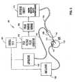
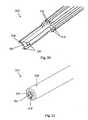
- the disclosed exemplary application of the system described hereinis for the treatment of pathologic retinal conditions whereby, as shown in Figure 1 , a hollow probe 114, as described herein, using a handle 120 is inserted by a surgeon into the posterior region of the eye 100 via a pars plana approach 101, as shown in Figure 3 .
- vitreous and/or intraocular membranes and tissueswould be engaged by the tip 112 of the hollow probe 114, irrigation 130 and aspiration 140 mechanisms would be activated, and ultrashort high-intensity pulsed electric power from a high voltage pulse generator 150 would be delivered through a pulse-forming network 160, switching circuit 170, and cable 124, creating a disruptive high-intensity ultrashort-pulsed electrical field within the entrained volume of tissue.
- the adhesive mechanisms of the entrained constituents of the tissue that are drawn toward the probe tip 112 via aspiration through an aspiration line 118 connected to an aspiration lumen 122 in the hollow probe 114would be dissociated, and the fluidic techniques employed would remove the disrupted tissue. Engagement may be axial to or lateral to the tip 112 of the hollow probe 114. Extracted tissue would be removed through the aspiration lumen 122 via a saline aspiration carrier to a distally located collection module.
- vitreous tissue, vitreoretinal membranes, and fibrovascular membranes from the posterior cavity of the eye and surfaces of the retinaare the critical processes pursued by vitreoretinal specialists, in order to surgically treat sight-threatening conditions, such as diabetic retinopathy, retinal detachment, proliferative vitreoretinopathy, traction of modalities, penetrating trauma, epi-macular membranes, and other retinopathologies.
- the device and modality described hereinis applicable to anterior ophthalmic treatments as well, including traction reduction (partial vitrectomy); micelle adhesion reduction; trabecular meshwork disruption, manipulation, reorganization, and/or stimulation; trabeculoplasty to treat chronic glaucoma; Schlemm's Canal manipulation, removal of residual lens epithelium, and removal of tissue trailers. Applicability of the disclosed apparatus to other medical treatments will become obvious to one skilled in the art.
- Control Unit180 ) Pulse Power Generator ( 150 ) Pulse-Forming Network ( 160 ) Switching Circuit ( 170 ) Transmission Line ( 124 ) Multi-Electrode Surgical Probe Assembly ( 110 ) Fluidics System ( 130 , 140 )
- the apparatus of the disclosed inventiondelivers pulsed high-intensity and ultrashort duration electrical field (low energy) at a pulse duration, repetition rate, pulse pattern, and pulse train length tuned to the properties of the components of the intraocular extracellular matrix (ECM).
- the pulse power generator 150 for the system 190delivers pulsed DC or gated AC against a low impedance of vitreous and the irrigating solution. Included in the system 190 are energy storage, pulse shaping, transmission, and load-matching components.
- the peak output voltage of the high voltage generator 150is sufficient to deliver up to a 300 kV/cm field strength using the electrodes 116 at the distal end 112 of the hollow surgical probe 114. Pulse duration would be short relative to the dielectric relaxation time of protein complexes.
- pulse duration, repetition rate, and pulse train lengthare chosen to avoid the development of thermal effects ("cold" process).
- the system 190generates and delivers square-shaped pulses with a fast ( ⁇ 5 nanoseconds) rise time and fall time.
- pulse durationswould be in the nanosecond range, and the voltage would be greater than one (1) kV and preferable in the range of tens (10s) of kV.
- a switching circuit 170is incorporated to control pulse duration, repetition rate, and generate a stepwise continual change in the direction of the electrical field by switching between electrodes, reversing polarity between electrodes or a combination of both in an array of electrodes at the tip 112 of the hollow probe 114, thus creating disorder in the electric field without causing dielectric breakdown of the carrier fluid between the electrodes or thermal effects.
- Paramount to the effectiveness of the disclosed inventionis the choice of energy.
- the objectis to create disorder among electrons in the outer shell of macromolecules associated with non-covalent bonds binding proteinaceous complexes together.
- the preferable form of energyis electricity - energizing electrons by the direct creation of an electrical field.
- Sources of energysuch as microwaves, laser, and ultrasound, which utilize photons and phonons to energize electrons may also be used to create the desired disorder among the electrons in the outer shell of macromolecules.
- the disclosed apparatusincludes a transmission line 124 and a hollow surgical probe 114 which delivers, channels, and distributes the applied energy in such a fashion as to create a confined, localized region of electrical force within a macroscopic volume of the extracellular matrix ECM (e.g., vitreous and intraocular membranes).
- ECMextracellular matrix
- the electrical fieldis presented essentially perpendicularly or orthogonally to the direction of carrier fluid movement (i.e., proteinaceous material in a water solution).
- Figures 4A , 4B , 4C , 4D , and 4Billustrate several possible electrode array embodiments at the distal end 112 of the surgical probe 114.
- reference number 1is used in Figures 4A , 4B , 4C , 4D , and 4E to refer to a polymer extrusion with one or more through lumens.
- Reference number 2designates the lumen for aspirated fluid flow.
- Reference numbers 3, 4, 5, 6, 7, 8, 9, and 10refer to the electrode wires embedded in extrusion 1.
- a centrally located electrode wire 11is used in Figures 4A , 4C , and 4D .
- a centrally located tubular electrode 12is used in Figure 4E .
- a centrally located lumen 13is used for fiberoptic equipment or some other form of instrumentation.
- each electrode 116may be axially staggered or aligned and may be either inset or protruding, or a combination of both, from the distal end 112 of the hollow probe 114. Though shown terminating in a plane perpendicular to the axial direction of the probe shaft, the electrodes 116 may terminate axially about a lateral window (not shown).
- the outside diameter of the extrusion 1is less than 0.1 cm (0.040 inches). It is envisioned that vitreous or intraocular tissue material would be drawn toward and into the aspiration channel(s), and, as the material approached the region orthogonal to the electrodes 116, the electrodes would be activated, creating an ultrashort, high-intensity disruptive electric field between electrodes 116.
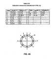
- Tables 5A, 58, 5C, 5D, and 5Eillustrate a plan of electrode activation for the embodiments shown in Figures 4A , 4B , 4C , 4D , and 4E , respectively.
- Table 5Athere are 12 pulses that are illustrative of a pulse sequence used on the embodiment of the end of the probe 114 shown in Figure 4A .
- the first pulseutilizes the electrode 116, given reference number 11, as an anode, and the cathodes are 3, 4, 5.
- the second pulseis just the opposite.
- the remaining pulsesare illustrative of a pulse arrangement to establish a variable direction electrical filed.
- a 10-pulse sequenceis shown for the probes shown in Figures 4D and 4E , respectively.
- Numerous other field patternsare envisioned, depending on the embodiment and the sequence of electrode activation.
- the object of the electrode activationis to utilize the polar properties of water and protein, create disorder with rapidly changing high-intensity electric field direction, and thus induce conformal changes of both water and protein, leading to momentary tissue dissociation.
- the dissociated tissue complex localized within the region of applied electrical fieldis then removed using concurrent fluidic techniques before the transient effects of the assault expire (relax).
- the central electrode 12may be a tubular conductive electrode with a center region 13.
- the central region 13could be a through lumen for an irrigation or instrument channel, or the central region could be a fiber-optic device for delivery of light.
- the position of electrodes in the arrays and the number of electrodesmay be configured to present the most efficacious disruptive electric fields.
- the electrodesmay also be axially positioned so that one or more of the electrodes does not terminate at the same length or same axial position.
- the terminal end of the electrodesmay be shaped in such a fashion as to optimize spatial field strength between the electrodes. Shapes of the terminal end of the electrodes may include straight edges, corners, sharps, curvatures (constant and variable) or combinations thereof chosen to project and optimize electric field strength distribution between the electrodes.
- Fluidic techniquesare included to draw in and remove the dissociated tissue volume before reassembly of non-covalent proteinaceous relationships can occur.
- the fluidic techniques used in the preferred embodimentinclude both saline irrigation and effluent aspiration.
- the fluidics systemincludes irrigation and aspiration features which are uniquely matched such that the volume and pressure within the eye are maintained within physiological limits.
- the posterior vitreouscontains more than 97% water, and an important function of the fluidics system is to ensure dilution, hydration and stable impedance of engaged material.
- the aspiration channelis incorporated into the hollow surgical probe 114 such that intraocular tissues are drawn into the aspiration lumen 122 or channels while being subjected to the disruptive electric field described above.
- the volume flow rate of the aspirated effluentis matched to the dissociation rate of the hydrated proteinaceous material under the influence of the disruptive electric field. It is anticipated that irrigation with BSS ® irrigating solution or BSS PLUS ® irrigating solution, both available from Alcon Laboratories, Inc., will be utilized. Innocuous properties and ingredients may be incorporated into the irrigation fluid to enhance dissociation.
- the irrigation route/channelmay be incorporated into the surgical probe, as illustrated in Figure 4E , it may be provided in an independent cannula, or it may be provided by a combination of both means.
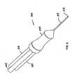
- FIG 6is a perspective of an alternate embodiment of a probe assembly 210 including three electrodes.
- the probe assembly 210includes a hollow probe 214 and a handle 220. Tissue would be engaged by the tip 212 of the hollow probe 214.
- the three electrodes 216are positioned at substantially equal angular intervals around a central spine 217 within the probe 214. Between the electrodes 216 are the irrigation channels 215. In the center of the central spine 217 is located an aspiration lumen 222. Covering the central spine 217, the irrigation channels 215, and the electrodes is an external jacket 219 which terminates in an atraumatic tip 221.
- the probe assembly 210is positioned so that the tissue to be removed is located just inside the atraumatic tip 221.
- the support system 290 for probe assembly 210is similar to that of the preferred embodiment shown in Figure 3 but for the inclusion of a probe tip irrigation system 235. Included is a global irrigation system 230, an aspiration system 240 connected to an aspiration line 218, a control unit 280, one or more high-voltage pulse generators 250, a switching circuit 270 connected to a transmission line 224, and a probe tip diluting irrigation system 235 connected to a probe tip irrigation tube 237 .
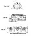
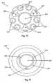
- Figures 11A and 11Billustrate alternate arrangements of electrodes 1, 2, 3, and 4 in the probe assembly 210.
- Figures 12A and 12Bcorrespond to Figures 11A and 11B showing exemplary sequences of electrode activation to create the non-plasma, non-contact energized disruptive region around the proteinaceous tissue.
- Figures 13A and 13Billustrate the field lines for the sequence of pulses illustrated in Figures 12A and 12B , respectively, where the polarity of the electrodes is not reversed.
- Figure 14is a schematic diagram of the three-channel pulse generator 250 which controls the duration of individual pulses, the repetition rate of the individual pulses, and the pulse length of the pulse train.
- Figure 15is a table illustrating the channel states of an exemplary single cycle of pulsing of the three-channel pulse generator 250 shown in Figure 14 .
- the probe assembly 210includes a plurality of through lumens 215 for supplemental irrigation, as shown in Figures 6 , 7, 8, and 9 , respectively.
- the flow rate of irrigationis less than the aspiration rate through the central lumen 222, such that the escape velocity of the supplemental irrigation fluid is less than the entrance velocity of diluted hydrated intraocular tissue.
- Additional irrigation fluidis presented by probe tip diluting irrigation mechanism 235 which is external to the probe ( Figure 10 ).
- the irrigation fluidis used both to dilute intraocular tissue and to maintain a stable or near constant impedance between the electrodes 216, thereby avoiding significant shifts in realized energy delivery and field strength. Properties of the irrigation fluid such as pH and ingredients may be chosen to enhance vitreous dissociation.
- a third conduit for irrigation 237connects the probe assembly 210 to the supplemental irrigation source 235. Also to be noted, in Figure 10 , the pulse forming network is incorporated into the high voltage pulse generator 250.
- the three-channel pulse generatorwhose schematic is illustrated in Figure 14 , shows that the triggering of one channel sends a pulse to an electrode, then triggers a second channel which, in turn, sends a pulse to a different electrode, then triggers the third channel which, in turn, sends a pulse to a different electrode and triggers the first channel to start the sequence over again.
- the other two channelsoffer zero resistance and act as return circuits for the fired pulse.
- the sequencing of channelsmay be ordered, or it may be random.
- Figure 15illustrates the polarity condition of each channel during a pulse firing.
- the polarity condition of each channelresults from electrode switching as opposed to actual polarity switching on any single channel.
- FIG. 16-23A further embodiment of probe assembly 210 is pictured in Figures 16-23 .
- Figures 16-19depict an embodiment with electrodes 216 that are flattened and axially elongated. These electrodes 216 are flattened with the large flat portion aligned radially with respect to the aspiration channel 222. The sharp corners of electrodes 216 allow for a more intensely focused electric field to be produced at the aspiration channel 222. These electrodes 216 terminate at the orifice of jacket 219.
- FIGS 20-23depict an embodiment with electrodes 216 that have pointed tips. These electrodes 216 are flattened with the large flat portion aligned radially with respect to the aspiration channel 222. These electrodes 216 terminate in a folded pointed tip with the pints directed radially inward toward the aspiration channel 222. The sharp corners of electrodes 216 allow for a more intensely focused electric field to be produced at the aspiration channel 222.
- the three electrodes 216are positioned at substantially equal angular intervals around a central spine 217 within the probe 214. Between the electrodes 216 are the irrigation channels 215. In the center of the central spine 217 is located an aspiration lumen 222. Covering the central spine 217, the irrigation channels 215, and the electrodes is an external jacket 219 which terminates in an atraumatic tip 221.
- the probe assembly 210is positioned so that the tissue to be removed is located just inside the atraumatic tip 221.
- an opening 227 between the jacket 219 and the aspiration channel 222allows irrigation fluid to pass in a waterfall effect near the electrodes 216.
Landscapes
- Health & Medical Sciences (AREA)
- Engineering & Computer Science (AREA)
- Life Sciences & Earth Sciences (AREA)
- Surgery (AREA)
- General Health & Medical Sciences (AREA)
- Veterinary Medicine (AREA)
- Heart & Thoracic Surgery (AREA)
- Biomedical Technology (AREA)
- Animal Behavior & Ethology (AREA)
- Nuclear Medicine, Radiotherapy & Molecular Imaging (AREA)
- Public Health (AREA)
- Ophthalmology & Optometry (AREA)
- Physics & Mathematics (AREA)
- Plasma & Fusion (AREA)
- Otolaryngology (AREA)
- Medical Informatics (AREA)
- Molecular Biology (AREA)
- Vascular Medicine (AREA)
- Medicines That Contain Protein Lipid Enzymes And Other Medicines (AREA)
- Surgical Instruments (AREA)
- Materials For Medical Uses (AREA)
- Peptides Or Proteins (AREA)
Description
- The present invention pertains to the dissociation and removal of highly hydrated macroscopic volumes of proteinaceous tissue; more particularly, the present invention pertains to the dissociation and removal of highly hydrated macroscopic volumes of proteinaceous tissue using rapid variable direction energy field flow fractionization.
- The present invention is described in terms of vitreoretinal surgery; however, those of ordinary skill in the art will understand the applicability of this invention to medical procedures in other areas in the body of humans or animals.
- For decades, prior art procedures for vitreoretinal posterior surgery have relied on mechanical or traction methods for: 1) tissue removal with shear cutting probes (utilizing either a reciprocating or rotary cutter); 2) membrane transection using scissors, a blade, or vitreous cutters; 3) membrane peeling with forceps and picks; and 4) membrane separation with forceps and viscous fluids. While improvements in mechanisms, materials, quality, manufacturability, system support, and efficacy have progressed, significant advancements in posterior intraocular surgical outcomes are primarily attributable to the knowledge, fortitude, skill, and dexterity of the operating ophthalmic physicians.
- Traction-free removal of intraocular tissue during vitreoretinal surgery is nearly impossible with the current arsenal of mechanical medical instruments. Through the application of skill, precise movement, experience, and knowledge, operating physicians have been able to minimize the traction from the use of mechanical medical instruments during tissue removal but are unable to eliminate it. Mechanical or traction surgical methods utilize a shearing action to sever tissue bonds. This shearing action inherently puts tension on the tissue to be removed, that tension, in turn, is transferred to the retinal membrane. Because of the use of mechanical or traction surgical methods, the forces which impart motion to the cutting element of the mechanical medical devices being used to sever tissue bonds are superimposed on the retinal membrane. Despite the skill and the care of the ophthalmic surgeon, this superimposition of the forces associated with traction surgical methods onto the retinal membrane gives rise to the possibility of damage to the retinal membrane.
- A potential traction-free surgical method that has been used in generating conformational changes in protein components involves the application of high intensity pulsed electrical fields; however, the use of a high-intensity pulsed electrical field has not made its way into delicate surgical procedures such as vitreoretinal surgery.
- High-intensity pulsed electric fields have found numerous applications in the medical field, the food industry, and in the machining of micromechanical devices. Examples of medical field use include delivery of chemotherapeutic drugs into tumor cells, gene therapy, transdermal drug delivery, and bacterial decontamination of water and liquid foods. In the food industry, high-intensity ultrashort-pulsed electric fields have found commercial use in sterilization and decontamination. Finally, the machining and surface modification techniques used for Micro Electric Mechanical Systems (MEMS) chips employ high-intensity ultrashort-pulsed electrical fields.
- Manipulation of biological structures, such as macromolecules, cellular membranes, intracellular organelles, and extracellular entities, has been the focus of recent research by both biophysics and biochemical engineering groups. Under the general heading of electrokinetics, the response of biological tissues to electric fields has been used in research, diagnostic, and therapeutic applications.
- Basic understanding of the invention described herein is best obtained through an appreciation of some of the prior-art nonsurgical technologies now in use for biochemical molecular research, therapeutic pharmaceutical developments, sterilization techniques, commercial polymerization, plasma research, and MEMS (lab-on-a-chip) advancements. Key aspects of these prior-art technologies are described below to demonstrate other systems in which proteinaceous material has been manipulated and compromised by the delivery of high-intensity pulsed electrical fields.
- Electrorheology (ER) is a phenomenon in which the rheology of fluids, to include biological fluids, is modified by the imposition of electrical fields (usually low DC fields). The electrical field imposed on the fluid induces a bulk-phase transition in the fluid with the strength of the electrical field being the most important _ parameter, and the frequency of the electrical field generally being the least important parameter. Most colloidal ER fluids demonstrate an increase in viscoelastic effects with increased field amplitude. Interestingly, a decrease in viscoelasticity of the fluid appears at the highest field strengths, but definitive research into the effect of field strength on viscoelasticity of the fluid is lacking, and the mechanism of ER remains unknown.
- Electrophoresis (or dielectrophoresis) involves the movement of particles in an electrical field toward one or another electric pole, anode, or cathode. The electrophoresis process is used to separate and purity biomolecules (e.g., DNA and RNA separation). For materials that are on the order of nanometers to micrometers, the electrophoresis process works well for both highly specific isolation of materials and determination of material properties. During electrophoresis, electrical field induced phase transition in a confined suspension is the subject of a spatially uniform AC electrical field. This electrical-field-induced phase transition follows the well-known field-induced formation of a columnar structure in a suspension. When subjected to an external electrical field, the particles within the electrical field align themselves along the field direction, forming chains and columns. The chains and columns of particles are then stretched by the actions of the electrical field and fluid flow. The time for separation and isolation of particles is on the order of minutes to hours and often involves the application of multiple secondary processes. An ionic surfactant (e.g., sodium dodecyl sulfate SDS) and sample dilution are often used to enhance macromolecular separation. Ionic surfactants have the ability to form a chemical bridge between hydrophobic and hydrophilic environments, thus disrupting or diminishing the hydrophobic connecting forces needed to maintain native protein structure.
- Field Flow Fractionation (FFF) is a laboratory solution separation method comparable in many ways to liquid chromatography. In general, both the materials and size range of materials separated in FFF systems are complimentary to those analyzed using electrophoresis and liquid chromatography. In FFF systems, the separation protagonist (electrical field) is applied in a direction perpendicular to the direction of separation and creates spatial and temporal separation of the sample components at the output of the FFF channel. Separation in an FFF channel is based on differences in the retention (time) of the sample components. In turn, the retention in FFF systems is a function of the differences in the physiochemical properties of the sample, the strength and mode of the applied assault, and the fluid velocity profile in the separation channel. Utilization of FFF has reduced electrophoresis times from hours to minutes.
- Arising from the work being done in machining Micro Electric Mechanical Systems (MEMS) is Electric Field Flow Fractionation (EFFF). EFFF is a process for the ex-vivo separation of nanoparticles, proteins, and macromolecules entrained in microchannels by applying electrical fields either in the axial or in the lateral direction. This technique is currently under study in connection with MEMS microphoresis devices. The method is based on axial flow of analyte under the action of an electrical potential (unidirectional lateral electrical field). The separation performance and the retention time of particulate samples in the flow channel depend on the interaction of the sample with the electrical field applied transverse to the flow field in the channel. Dissociation of protein complexes, disruption of protein connections, and subsequent fractionization has been achieved with EFFF. An increase in retention, resulting in much better separation, has also been seen with the application of periodic (oscillating) electrical fields in EFFF.
- In addition, the application of pulsed potentials with alternating polarity has been shown to increase the effectiveness of the electrical field. It has been postulated that shear plays a significant role in chain scission, since local deformation of proteinaceous tissue in any electrical field gradient is pure elongation. Quantified by a strain rate and axes of extension and compression, careful manipulation of array geometry and flow-field strength can result in significant extension of the majority of the macromolecules. Microchips have been designed that can generate rotational, extensional, and shear electrical field patterns, as long as the input voltages are changed. Separation time on a 1.25 cm chip has been reduced to approximately 5 seconds.
- Electroporation is another nonsurgical prior-art technology that has been used to reversibly and transiently increase the permeabilization of a cell membrane. Introduced in about 1994, electroporation (EP) to enhance the delivery of drugs and genes across cell membranes in-vitro has become a standard procedure in molecular biology laboratories in the last decade. Electroporation is a technique in which pulses of electrical energy, measured in kilovolts per centimeter, having a duration in the microsecond-to-millisecond range, cause a temporary loss of the semi-permeability of cell membranes. This temporary loss of the semi-permeability of cell membranes leads to ion leakage, escape of metabolites, and increased cellular uptake of drugs, molecular probes, and DNA. Some prior-art applications of electroporation include introduction of plasmids or foreign DNA into living cells for transfection, fusion of cells to prepare hybridomas, and insertion of proteins into cell membranes. Classically, pulse durations in the order of 0.1 to 10 milliseconds and electrical field strength of kV/cm, depending on cell type and suspension media, have been utilized. The mechanism of electroporation (i.e., the opening and closing of cellular channels) is not completely understood.
- Adaptations of the electroporation technology have been used for drug delivery.
U.S. Patent 5,869,326 and PublishedU.S. Patent Application 2004/0176716 both describe instruments for transcutaneous drug delivery. PublishedU.S. Patent Application 2004/021966 describes a catheter instrument for intravascular delivery of therapeutic drugs and in-vitro drug delivery using electrode array arrangements.U.S. Patent 6,653,114 teaches a means for electrode switching.U.S. Patent 6,773,736 andU.S. Patent 6,746,613 have adapted electroporation technology to decontaminate products and fluids by causing cell deactivation and death.U.S. Patent 6,795,728 uses electroporation-induced cell death as the basis for an apparatus and method for reducing subcutaneous fat deposits in-vivo. WO-01/10319-A - Nanosecond Pulsed Electrical Field (nsPEF) technology is an extension of electroporation technology described above, to include in-vivo application, where a square or trapezoidal pulse formed with significantly shorter duration (1-300 ns), together with considerably higher electric fields (up to 300 kV/cm), is utilized. nsPEF evolved from advances in pulse-power technology. The use of this pulse-power technology has lead to the application of nanosecond-pulsed electronic fields (nsPEF) with field intensities several hundred times higher than the pulses of electrical energy used in electroporation to cells and tissues without causing biologically significant temperature increases in the samples tested. Using very few pulses of electrical energy, the effects of nsPEF are essentially non-thermal. In contrast to classical electroporation techniques, the effects of nsPEF on mammalian cells have only recently been explored. Application of nsPEF of appropriate amplitude and duration creates transient cellular permeability increases, cellular or subcellular damage, or even apoptosis. In in-vivo nanosecond electroporation, the goal is to obtain an even distribution of an efficacious electrical field within a narrow time window.
- Current research has shown that the application of nanosecond pulses (kV/cm) to tissues can energize electrons without heating ions or neutral particles. It has been found that an ultrashort-pulsed energy field (Electromagnetic EM, Laser, or High Intensity Focused Ultrasound HIFU) can be used to temporarily and reversibly increase the permeability of cell membranes or even compromise intracellular components without affecting the cell membrane. It has also been found that higher energies will excite ions and may cause the formation of short-lived radicals (OH and O2+). This finding has lead to the development of processes for sterilization and decontamination whereby cells are killed. The use of still higher energies may cause the formation of super-charged plasma arcs which attack cellular bonds at the molecular level.
- Electro-osmosis (EO) is a technique used to transport or mix fluid for use in micro devices. A key concept is to exploit different charging mechanisms and polarization strength of the double layer at the electrode/electrolyte interface, to produce a unidirectional Maxwell force on the fluid, which force generates throughflow pumping. In "induced-charge electro-osmosis" (ICEO), an effect is created which produces microvortices within a fluid to enhance mixing in microfluidic devices. Mixing can be greatly enhanced in the laminar flow regime by subjecting the fluid to chaotic-flow kinematics. By changing the polarity and the applied voltage, the strength and direction of the radial electro-osmotic flow can be controlled.
- Electrokinetic phenomena are not limited to that described above. Recent variants associated with very large voltages and unique electrical fields in MEMS research have demonstrated interesting and counter-intuitive effects occurring with variable applied electrical fields, including the finding that the electrophoretic mobility of colloids is sensitive to the distribution of charges, rather than simply the total net charge.
- All of the processes described above are applicable to manipulation of macromolecules, but not to the extraction or removal of macroscopic volumes of proteinaceous tissue by tissue dissociation. As other systems using pulsed energy with tissues employ high levels of energy, it has been found that higher energies delivered through the use of longer pulse durations, pulse trains, repetition rates, and exposure times will cause thermal effects or the formation of super-charged plasma. These thermal effects or the formation of super-charged plasma have been effectively utilized in several devices to develop surgical instruments for tissue cutting. In these instruments, a microsize (thickness or projection) plasma region is created about an instrument. Within the super-charged plasma are charged electrons, ions, and molecules with an erratic motion which, when contacted with tissues or cells, attack bonds at the molecular level - thereby ablating or obliterating via sublimation the target tissue or tissue surface. The formation of super-charged plasma relies on electron avalanche processes - high rate of tunneling by electrons from the valence band to the continuum to form electron plasma avalanche ionization. The density of this super-charged plasma rapidly builds up by virtue of additional tunneling as well as field-driven collisions between free electrons and molecules. A major goal of the treatment of tissue with super-charged plasma is nondestructive surgery; that is, controlled, high-precision removal of diseased sections with minimum damage to nondiseased tissue. The size and shape of the active plasma are controlled by probe design, dimensions, and media. Both gaseous and fluid media have been employed. Within a liquid, an explosive vapor may be formed.
- The Pulsed Electron Avalanche Knife (PEAK) disclosed in Published
U.S. Patent Application 2004/0236321 is described as a tractionless cold-cutting device. A high electrical field (nsPEF 1 to 8 kV, 150 to 670 uJ) is applied between an exposed microelectrode and a partially insulated electrode. The application of this high electrical field leads to a plasma formation manifested in the form of micrometer-length plasma streamers. It is the size of the exposed electrode which controls the dimensions of the plasma streamers. The plasma streamers, in turn, create an explosive evaporation of water on a micron scale. Pulsed energy is critical. Precise, safe, and cost-effective tissue cutting has been demonstrated. Even with the electrode scaled down in size to the micron level, the plasma discharges must be confined to the probe tip, because ionization and explosive evaporation of liquid medium can disrupt the adjacent tissue and result in cavitation bubble formation. The high pressure achieved during plasma formation, the fast expansion of vapor bubble (>100 m/sec), and the subsequent collapse of the cavity that can extend the zone of interaction is mainly mechanical due to rapid bubble vapor cool down. In ophthalmic surgery, the volatility and aggressiveness of the effect caused by the use of a PEAK could be detrimental to retinal integrity. - Coblation, or "Cold Ablation," uses radio frequency RF in a bipolar mode with a conductive solution, such as saline, to generate plasma which, when brought into contact with a target tissue, sublimates the surface layer of the target tissue. The range of accelerated charged particles is short and is confined to the plasma boundary layer about the probe and to the surface of tissue contact. Coblation energizes the ions in a saline-conductive solution to form a small plasma field. The plasma has enough energy to break the tissue's molecular bonds, creating an ablative path. The thermal effect of this process has been reported to be approximately 45-85° C. Classically, RF electrosurgical devices use heat to modify tissue structure. The generation of a radio frequency induced plasma field, however, is viewed as a "cold" process, since the influence of the plasma is constrained to the plasma proper, and the plasma layer maintained is microscopically thin. The plasma is comprised of highly ionized particles of sufficient energy to achieve molecular dissociation of the molecular bonds. The energy needed to break the carbon-carbon and carbon-nitrogen bonds is on the order of 3-4 eV. It is estimated that the Coblation technique supplies about 8 eV. Due to the bipolar configuration of the electrodes and the impedance differential between the tissues and the saline solution, most of the current passes through the conductive medium located between the electrodes, resulting in minimal current penetration into the tissue and minimal thermal injury to the tissue. If the threshold of energy required to create plasma is not reached, current flows through the conductive medium and the tissue. Energy absorbed by both the tissue and the conductive medium are dissipated as heat. When the threshold of energy needed to create plasma is reached, impedance to RF current flow changes from almost purely resistive-type impedance into a more capacitive-type impedance. Similar to the drawbacks of the PEAK for ophthalmic surgery, the use of coblation techniques may be too aggressive for surgical applications near the retina.
DE-197 40 530 is further representative of the art of RF tissue removal.- The plasma needle is yet another device that allows specific cell removal or rearrangement without influencing surrounding tissue. Use of the plasma needle is a very exalting technique which utilizes a microsize needle affixed to a hand-operated tool to create a small plasma discharge. An electrical field is created between the needle tip and a proximal electrode with an inert gas (helium) flowing there between. The small plasma discharge contains electrons, ions, and radicals - with the ions and radicals controllable by the introduction of a contaminant, such as air, into the inert gas. It has been postulated that the small size of the plasma source (plasma needle) creates ROS (reactive oxygen species) and UV light emissions at such minute levels as to alter cell function or cell adhesion without damaging the cells themselves. However, an increase in ROS (i.e., air) in the inert gas along with an increased irradiation time can lead to cell death. While shown to exert an influence across thin liquid layers, use of the plasma needle is not optimal in a total liquid environment, as often found in ophthalmic surgery.
- Spark erosion technology is a cousin to the plasma technologies discussed above. The spark erosion device utilizes a pulsed energy field of 250 kHz, 10 ms duration, and up to 1.2 kV to produce a vapor. As the electric breakdown of vapor occurs, a small spark (<1 mm) is formed. With up to a 1.7 mm far-field effect, the cutting performance from spark erosion is similar to electrosurgery, but, like plasma — only the plasma contacts tissue.
- Lasers represent another traction-free technology that has been used to break down tissue macro molecules. Lasers have been utilized in ophthalmic surgery since about 1960. The greatest success in laser usage has been in the area of non-invasive retinal coagulation in diseases such as diabetic retinopathy, central vein occlusion, and choroidal neovascularization in age-related macular degeneration or ischemic retinal vasculitis. Lasers have also been used extensively in anterior eye applications for such applications as corneal sculpting and glaucoma. Attempts to utilize lasers in posterior ophthalmic surgeries have achieved mixed results. Non-invasive (transcorneal/lens or trans-sclera) techniques are not practical, due to the absorptive properties of these intervening tissues. The extraordinary precision needed in intraocular surgery of the retina and vitreous requires the use of increasingly refined invasive techniques for tissue manipulation and removal. The tissue/laser interaction regimes include 1) thermal - conversion of electromagnetic energy into thermal energy; 2) photochemical - intrinsic (endogenous) or injected (exogenous) photosensitive chemicals (chromophores), activated by absorption of laser photos; 3) photoablative - direct photodissociation of intramolecular bonds of absorption of photons; and 4) electromechanical - thermionic emission or multiphoton production of free electrons leading to dielectric breakdown and plasma production. It has been found that lasers are costly and require the use of shields and backstops on uniquely designed laser probes to protect fine intraocular tissues from stray laser energy and far-field thermal effects. However, recent developments in femtosecond-pulsed lasers have opened new possibilities in fine surgical applications.
- Methods currently employed to disrupt intraocular tissues include morcellation (fragmentation), which is the objective of mechanically shearing vitrectomy devices; liquefaction as accomplished by thermal (protein denaturizing) or enzymatic reactions; and sublimation via laser or plasma treatments. Sublimation via laser or plasma treatments actually compromises bonds on a molecular level, whereas morcellation and liquefaction affect the binding mechanism of lesser strength (i.e., non-covalent bonds).
- Accordingly, despite many advances in vitreoretinal surgery, a need still remains for an effective apparatus and method for the dissociation and removal of highly hydrated macroscopic volumes of protein tissues, such as vitreous and intraocular tissues, during vitreoretinal surgery.
- The present invention describes an apparatus for the dissociation and removal of highly hydrated macroscopic volumes of proteinaceous tissues, such as vitreous and intraocular tissue, during vitreoretinal surgery.
- While the disclosed invention is described in terms of an instrument for traction-free removal of vitreous and intraocular membranes from the posterior region of the eye without damaging the ultrafine structure and function of the adjacent or adherent retina, those of ordinary skill in the art will understand the applicability of the disclosed invention for other medical procedures on both humans and animals.
- The disclosed invention is described in terms of a new means of performing vitreoretinal surgery using a high-intensity short directionally changing electrical field, as opposed to classical mechanical means to engage, decompose, and remove vitreous and intraocular tissues. Specifically, the following disclosure affects the discovery that a transient change in tissue condition caused by the application of a high-intensity short directionally changing electrical field is satisfactory for removal of macroscopic volumes of proteinaceous tissue. The technical success of mechanical and liquefying means supports the contention that vitreous material need not be obliterated or disrupted on a molecular level to be removed - but, rather, an innocuous macroscopic change of state is all that is needed for tissue removal. Accordingly, the removal of intraocular tissue enabled by the disclosed invention is entirely traction-free.
- The apparatus disclosed herein causes a local temporary dissociation of the adhesive and structural relations in components of intraocular proteinaceous tissue using a rapidly changing electrical field. This localized temporary dissociation of the adhesive and structural relations between components of intraocular proteinaceous tissue enables tractionless detachment between intraocular tissue components and the retinal membrane. Fluidic techniques (irrigation and aspiration) are utilized during the tissue dissociation process to enhance the formation of a high-intensity ultrashort-pulsed electrical field and to remove disrupted tissue at the moment of dissociation. It is intended that only the material within the applied high-intensity ultrashort-pulsed electrical field is assaulted and removed. Therefore, because only the material assaulted by the applied ultrashort pulses receives the high-intensity ultrashort-pulsed electrical field, there is no far-field effect during the tissue extraction process.
- The design of the probe used to create the pulsed electrical field coupled with the use of fluidic techniques entrains the target macroscopic volume of tissue to be dissociated. Simultaneously, therefore, the entrained target macroscopic volume of intraocular tissue is subjected to a high-intensity ultrashort-pulsed electric field assault. This high-intensity ultrashort-pulsed electrical field assault leads to dissociation of the entrained macroscopic volume of intraocular proteinaceous tissue, and then aspiration removes the dissociated entrained macroscopic volume of tissue.
- According to the disclosed invention, a probe with two or more electrodes is inserted into the target hydrated tissue, vitreous or intraocular tissue. The ends of the electrodes are exposed at the distal end of the probe. An electrical pulse is transmitted down at least one of the electrodes while the other one or more electrodes act as the return conductors. A non-plasma electrical field is created between the delivery electrode(s) acting as an anode and the return electrode(s) acting as a cathode. With each electric pulse, the direction of the created electrical field is changed by reversing polarity, by electrode switching or by a combination of both. Pulses may be grouped into burst reoccurring at different frequencies and different amplitudes. Such pulse groups may be directed at heterogeneous tissue. The electrical pulse amplitude, duration, duty cycle and repetition rate along with continual changing of field direction, create the disruptive electrical field created across the orifice of the aspiration lumen. Tissue is drawn into the orifice of the aspiration lumen by fluidic techniques (aspiration). The tissue is then mixed or diluted with irrigation fluid and disassociated as it traverses the high-intensity ultrashort-pulsed directionally changing electric field. At any given instant, disorder is created in the electrical field by changing the direction of the electrical field between one or more of the electrodes at the tip of the probe. The affected medium between the electrode terminations at the end of the probe consists of a mix of target tissue (e.g. vitreous) and supplemental fluid (irrigation fluid). The electrical impedance of this target medium in which the electrical field is created is maintained by the controlled delivery of supplemental fluid (irrigation fluid). In the preferred embodiment, the supplemental fluid providing the electrical impedance is a conductive saline. The supplemental fluid may be provided by an irrigation source external to the probe, through one or more lumens within the probe or a combination of both. When the supplemental fluid is provided within an constrained to the probe interior, the supplemental fluid may have properties (e.g. pH) and ingredients (e.g. surfactants) that may be conducive to protein dissociation.
- Critical to the operation of the disclosed invention are the properties of the generated electrical energy field within the target medium. Herein, high-intensity, ultrashort pulses (sub-microseconds) of electrical energy are used. Tissue impedance, conductivity and dilution are maintained in the target medium by supplemental fluid irrigation. The pulse shape, the pulse repetition rate, and the pulse train length are tuned to the properties of the intraocular tissues. Multiple pulse patterns may be employed to address the heterogeneity of intraocular tissue. In addition, the spatial termination and the activation sequence of the electrodes at the tip of the probe, along with the generated field profile, play a significant role in tissue decomposition. The fluid aspiration rate is matched to the tissue dissociation rate. The pulsed rapid disruptive electric field effect in the target medium is of such high intensity, but such short duration (i.e., low energy), that the actual dissociation of the targeted tissue from surrounding tissue is a transient effect (microseconds to milliseconds), which is non-thermal, and devoid of explosive cavitation.
- The energies delivered by the ultrashort duration, high-intensity electrical pulses do not cause plasma formation; thus, there is no aggressive far-field effect. The ultrashort duration, high-intensity electrical pulses are used to create a non-contact disruptive electrical force within the tissue, not by an electron avalanche but, rather, by a continual change in field direction. Specifically, a non-plasma, non-contact energized region of disorder is created in the proteinaceous tissue to be dissociated. Any charged material entering into the electric field will be affected by that field, and intraocular tissues (e.g., proteins) will be changed. By creating a disruptive electric field about proteinaceous tissues without creating an electron avalanche, the attachment mechanisms between the tissue components experience a transient compromise. This transient compromise leads to a dissociation of tissue components - free of far-field perturbations. This transient compromise of tissue attachment mechanisms between the tissue complexes leads to the unfolding of protein complexes and the uncoiling of helices, thereby allowing for disruption of collagen segments and adhesive bonds (fragmentation of staggered fibrils).
- The intended purpose of the work leading to the discovery of the disclosed invention described herein has been the tractionless extraction of vitreous and intraocular membranous tissues from the posterior intraocular region of the eye. The disclosed apparatus engages and disrupts a hydrated proteinaceous gel matrix causing a transient compromise or dissociation of the adhesive mechanisms between tissue components. During this transient compromise or dissociation of the adhesive mechanisms between tissue components, fluidic techniques are employed to dilute and aspirate the dissociated tissue complex from the surrounding tissue.
- The purpose of the system disclosed herein is also to alter the state of vitreous proteinaceous tissue for safe removal. This alteration of the state of vitreous proteinaceous tissue entails the disruption of proteinaceous tissue component interactions, the promotion of separation and detachment of proteinaceous tissue components from adjacent structures, and, while proteinaceous tissue components are separated and detached - their removal.
- Accordingly, it is and object of this disclosure to present a new surgical device modality and device that addresses the needs of the modem vitreoretinal surgeon - namely, a device for improved and more precise extraction of vitreous and intraocular membranes while preserving retinal integrity. Though this disclosed system is focused on a new device for altering the state of and removal of the corpus vitreous and associated intraocular membranes, it will become obvious to one skilled in the art that the information presented herein is applicable to other surgical arenas besides ophthalmology.
- A better understanding of the disclosed system for dissociation and removal of proteinaceous tissue may be had by reference to the drawing figures wherein:
Figure 1 is a perspective view of a probe used for intraocular posterior surgery on which the system of the disclosed invention is used;Figure 2 is an enlarged perspective view of the tip of the probe shown inFigure 1 ;Figure 3 is a schematic diagram of a preferred embodiment of the disclosed system;Figures 4A ,4B ,4C ,4D , and4E are front views of alternative placements of electrodes on the tip of the probe;- Tables 5A, 5B; 5C, 5D, and 5E are activation schemes associated with the probe arrays shown in
Figures 4A ,4B ,4C ,4D , and4E , respectively; Figure 6 is a perspective view of three electrode embodiment of the probe used for intraocular posterior surgery employing the system of the disclosed invention;Figure 7 is an enlarged perspective view of the tip of the probe shown inFigure 6 including a transparent cover to reveal the interior features;Figure 8 is an end view of probe shown inFigure 7 ;Figure 9 is an expanded perspective view of the probe similar to that shown inFigure 7 ;Figure 10 is a schematic diagram of an alternate embodiment of the disclosed system with a supplemental irrigation means included in the probe;Figure 11A is an end view of the probe tip showing the placement of three electrodes as in the embodiment shown inFigures 7, 8, and 9 ;Figure 11B is an end view of a probe tip having four electrodes;Figure 12A is an activation scheme associated with the electrode array shown inFigure 11 A;Figure 12B is an activation scheme associated with the electrode array shown inFigure 11B ;Figure 13A is an illustration of exemplary field lines resulting from placement of a charge on one or more of the electrodes displayed inFigure 11A ;Figure 13B is an illustration of exemplary field lines resulting from placement of a charge on one or more of the electrodes displayed inFigure 11B ;Figure 14 is a schematic diagram of an exemplary three-channel pulse generator used with a three-electrode probe;Figure 15 is a schematic diagram of the channel states during a single cycle of pulsing of the generators shown inFigure 14 ;Figure 16 is an enlarged perspective view of another embodiment of the tip of the probe shown inFigure 6 including a transparent cover to reveal the interior features;Figure 17 is an enlarged perspective view of the probe shown inFigure 16 including a jacket that covers the interior features;Figure 18 is an end view of probe shown inFigure 16 ;Figure 19 is an end view of probe shown inFigure 17 ;Figure 20 is an enlarged perspective view of another embodiment of the tip of the probe shown inFigure 6 including a transparent cover to reveal the interior features;Figure 21 is an enlarged perspective view of the probe shown inFigure 20 including a jacket that covers the interior features;Figure 22 is an end view of probe shown inFigure 20 ; andFigure 23 is an end view of probe shown inFigure 21 .- Liquefaction (synchysis) is manifested in vitreous portion of the eye as a natural consequence of aging. As an individual reaches 70 to 90 years, roughly 50% of the vitreous gel structure has gone through a change of state or become liquefied. The results of synchysis are realized in the posterior vitreous as a destabilization of the vitreous matrix, dissolution of HA-collagen coupling, unwinding of collagen helices, molecular rearrangements, increases in the volume of liquefied spaces, loosening of entangled tethers, increases in vitreous detachment from the retina, collagen fiber fragmentation and aggregation, and loss of proteoglycans, non-covalent bound macromolecules and adhesive collagen (type IX). At the cellular level, many of the activities leading to liquefaction in the vitreous portion of the eye may be emulated by the present invention.
- The apparatus of the disclosed invention delivers a variable direction, pulsed high-intensity and ultrashort duration disruptive electric field (low energy) at a pulse duration, repetition rate, pulse pattern, and pulse train length tuned to the properties of the components of the intraocular extracellular matrix (ECM) to create a short period of tissue dissociation. The recommended modality of ultrashort-pulsed disruptive electric field application relies on the delivery of high powers of low energy.
- As shown in
Figure 1 , the disclosed apparatus for implementing the current invention includes aprobe assembly 110 which delivers, channels, and distributes the energy applied to the soft tissue in such a fashion as to create a confined, localized, non-thermal dynamic region of electrical forces within a macroscopic volume of the extracellular matrix ECM (e.g., vitreous and intraocular membranes) leading to momentary dissociation of proteinaceous complexes and local liquefaction of the entrained macroscopic volume of tissue. Thetip 112 of thehollow probe 114 is positioned to encircle the entrained macroscopic volume of proteinaceous tissue. Fluidic techniques (irrigation) are used first to provide a region of stable impedance and dilution between theelectrodes 116 at thetip 112 of thehollow probe 114 and then draw in and remove (aspiration) the affected macroscopic volume of proteinaceous tissue before the reassembly of non-covalent proteinaceous relationships can occur. The fluidic techniques used with theprobe assembly 110 may include both saline irrigation and effluent aspiration. - The directionally changing electrical field created at the
tip 112 of thehollow probe 114 is presented substantially perpendicular or orthogonal to the direction of carrier fluid movement (i.e., proteinaceous material in a water solution). The direction of the electrical field is changed with every or nearly every pulse. Pulse duration (nanoseconds) is short, relative to the dielectric relaxation time of protein complexes (~1 ms). Multiple pulse direction changes may occur within the dielectric relaxation time interval. Pulse duration, pulse repetition rate, pulse pattern, and pulse train length are chosen to avoid the development of thermal effects ("cold" process). The disclosed system generates and delivers square-shaped pulses of variable direction with fast (<5 nanoseconds) rise time and fall time. The shorter the rise and fall times of the pulse, the higher the frequency components in the Fourier spectrum of the pulse and, consequently, the smaller the structures that can be affected by the pulse. In the system for dissociation and removal of proteinaceous tissue disclosed herein, pulse durations are in the nanosecond range, and the electric field strength would be greater than 1 kV/cm, preferably in the range of hundreds (100s) of kV/cm. - The apparatus utilizes ultrashort chaotic high-intensity pulsed electric field flow fractionation (CHIP EFFF) to engage, dissociate, and remove vitreous and intraocular membranous material. A stepwise continual change in direction of the field (by use of an array of electrodes116) created by reversing polarity, switching active electrodes or a combination of both is incorporated into the
tip 112 of thehollow probe 114 to create a disruptive effect on charges involved in the non-covalent bonds holding the vitreous complexes (groups of proteins) together. By making the macroscopic volume of intraocular electrically unstable tissue, it is possible to further weaken the hydrophobic and hydrostatic bonds within the captured proteinaceous tissue, membranes, and multi-component enzymes, thereby increasing the fluidity or liquefaction of the tissue. The resulting assault on the hydrophobic and hydrostatic bonds of the proteinaceous tissue is sufficient for a momentary compromise of the binding mechanisms of the adhesive macromolecules of the vitreous and associated intraocular tissue, thereby temporarily reducing a minute portion of the bulk vitreous material to a manageable free proteinaceous liquid complex. - Paramount to the efficacy of the disclosed invention is the choice of energy. The object of the assault on the bonds which hold proteinaceous tissue together is to create disorder among electrons in the outer shell of the macromolecules associated with non-covalent bonds. The preferable form of energy is electricity - energizing electrons by the direct creation of an electric field. Other sources of energy, such as microwaves, and ultrasound which utilize photons and phonons to energize electrons, may also be used to create a disruptive field. It is appreciated herein that lasers, particularly those operating with pulse durations in the femtosecond range and at frequencies substantially at the peak absorption frequency of water, may also be utilized as an alternative energy source.
- In the preferred embodiment of the apparatus disclosed herein, a rapid variable direction electric field flow fractionation is used to engage, to dissociate, and to remove vitreous and intraocular membranous material. Specifically, the disclosed system utilizes high-intensity ultrashort-pulsed disruptive electrical field characterized by continuous changes of field direction coupled with fluidic techniques both to facilitate creation of the electrical field and then to remove the proteinaceous dissociated tissue. The high-intensity ultrashort-pulsed disruptive electric field is generated using field strengths on the order of kV/cm with pulse widths on the order of nanoseconds. The high-intensity ultrashort-pulsed disruptive electrical field is kept substantially orthogonal to the direction of aspirating carrier fluid flow. A stepwise continual change in the direction of the high-intensity ultrashort-pulsed disruptive Electrical field (created by reversing polarity or switching between an array of electrodes) is adopted to create disorder among the electrons involved in the non-covalent bonds holding the tissue complexes (groups of proteins) together. Using pulse durations and pulse trains that are short with respect to the time required for thermal effects, the assault on the tissue-binding mechanisms is essentially a "cold" process and sufficient for momentary tissue matrix dissociation. The assault on the tissue-binding mechanisms will compromise the binding mechanisms of the adhesive macromolecules of the vitreous and associated intraocular tissue, thereby temporarily reducing a minute portion of the bulk vitreous material to a manageable proteinaceous liquid complex. The strength of the electrical field causing the disassociation obeys the inverse square law. As such, the strength of the field is highest in region between electrodes. In the preferred embodiment, this distance is less than 0.5 millimeters. The affected proteinaceous liquid complex is localized within the region of applied pulsed rapid variable direction electrical field between probe electrodes and is removed using fluidic techniques (aspiration) before the transient effects of the assault on the tissue-binding mechanism expire (relax). Once the volume of proteinaceous tissue is in the extraction channel (i.e., within the fluidic aspiration stream), the state of the altered proteinaceous complex may return to a quasi pre-assault state.
- The disclosed exemplary application of the system described herein is for the treatment of pathologic retinal conditions whereby, as shown in
Figure 1 , ahollow probe 114, as described herein, using ahandle 120 is inserted by a surgeon into the posterior region of theeye 100 via apars plana approach 101, as shown inFigure 3 . Using standard visualization process, vitreous and/or intraocular membranes and tissues would be engaged by thetip 112 of thehollow probe 114,irrigation 130 andaspiration 140 mechanisms would be activated, and ultrashort high-intensity pulsed electric power from a highvoltage pulse generator 150 would be delivered through a pulse-formingnetwork 160, switchingcircuit 170, andcable 124, creating a disruptive high-intensity ultrashort-pulsed electrical field within the entrained volume of tissue. The adhesive mechanisms of the entrained constituents of the tissue that are drawn toward theprobe tip 112 via aspiration through anaspiration line 118 connected to anaspiration lumen 122 in thehollow probe 114 would be dissociated, and the fluidic techniques employed would remove the disrupted tissue. Engagement may be axial to or lateral to thetip 112 of thehollow probe 114. Extracted tissue would be removed through theaspiration lumen 122 via a saline aspiration carrier to a distally located collection module. - All of the posterior vitreous tissue could be removed, or just specific detachments of vitreous tissue from the retina or other intraocular tissues or membranes could be realized.
- Engagement disruption and removal of vitreous tissue, vitreoretinal membranes, and fibrovascular membranes from the posterior cavity of the eye and surfaces of the retina are the critical processes pursued by vitreoretinal specialists, in order to surgically treat sight-threatening conditions, such as diabetic retinopathy, retinal detachment, proliferative vitreoretinopathy, traction of modalities, penetrating trauma, epi-macular membranes, and other retinopathologies.
- Though intended for posterior intraocular surgery involving the vitreous and retina, it can be appreciated that the device and modality described herein is applicable to anterior ophthalmic treatments as well, including traction reduction (partial vitrectomy); micelle adhesion reduction; trabecular meshwork disruption, manipulation, reorganization, and/or stimulation; trabeculoplasty to treat chronic glaucoma; Schlemm's Canal manipulation, removal of residual lens epithelium, and removal of tissue trailers. Applicability of the disclosed apparatus to other medical treatments will become obvious to one skilled in the art.
Parts of System:
Control Unit (180)
Pulse Power Generator (150)
Pulse-Forming Network (160)
Switching Circuit (170)
Transmission Line (124)
Multi-Electrode Surgical Probe Assembly (110)
Fluidics System (130,140) - The apparatus of the disclosed invention delivers pulsed high-intensity and ultrashort duration electrical field (low energy) at a pulse duration, repetition rate, pulse pattern, and pulse train length tuned to the properties of the components of the intraocular extracellular matrix (ECM). The
pulse power generator 150 for thesystem 190 delivers pulsed DC or gated AC against a low impedance of vitreous and the irrigating solution. Included in thesystem 190 are energy storage, pulse shaping, transmission, and load-matching components. The peak output voltage of thehigh voltage generator 150 is sufficient to deliver up to a 300 kV/cm field strength using theelectrodes 116 at thedistal end 112 of the hollowsurgical probe 114. Pulse duration would be short relative to the dielectric relaxation time of protein complexes. Also, pulse duration, repetition rate, and pulse train length (i.e., duty cycle) are chosen to avoid the development of thermal effects ("cold" process). Thesystem 190 generates and delivers square-shaped pulses with a fast (<5 nanoseconds) rise time and fall time. In the apparatus disclosed herein, pulse durations would be in the nanosecond range, and the voltage would be greater than one (1) kV and preferable in the range of tens (10s) of kV. - A switching
circuit 170 is incorporated to control pulse duration, repetition rate, and generate a stepwise continual change in the direction of the electrical field by switching between electrodes, reversing polarity between electrodes or a combination of both in an array of electrodes at thetip 112 of thehollow probe 114, thus creating disorder in the electric field without causing dielectric breakdown of the carrier fluid between the electrodes or thermal effects. - Paramount to the effectiveness of the disclosed invention is the choice of energy. The object is to create disorder among electrons in the outer shell of macromolecules associated with non-covalent bonds binding proteinaceous complexes together. The preferable form of energy is electricity - energizing electrons by the direct creation of an electrical field. Sources of energy, such as microwaves, laser, and ultrasound, which utilize photons and phonons to energize electrons may also be used to create the desired disorder among the electrons in the outer shell of macromolecules.
- The disclosed apparatus includes a
transmission line 124 and a hollowsurgical probe 114 which delivers, channels, and distributes the applied energy in such a fashion as to create a confined, localized region of electrical force within a macroscopic volume of the extracellular matrix ECM (e.g., vitreous and intraocular membranes). The electrical field is presented essentially perpendicularly or orthogonally to the direction of carrier fluid movement (i.e., proteinaceous material in a water solution).Figures 4A ,4B ,4C ,4D , and4B illustrate several possible electrode array embodiments at thedistal end 112 of thesurgical probe 114. - For example,
reference number 1 is used inFigures 4A ,4B ,4C ,4D , and4E to refer to a polymer extrusion with one or more through lumens.Reference number 2 designates the lumen for aspirated fluid flow.Reference numbers extrusion 1. InFigures 4A ,4C , and4D , a centrally locatedelectrode wire 11 is used. InFigure 4E , a centrally locatedtubular electrode 12 is used. Also inFigure 4E , a centrally locatedlumen 13 is used for fiberoptic equipment or some other form of instrumentation. Those of ordinary skill in the art will understand that numerous other configurations are possible to generate the desired pulsed rapid strong electrical field pattern. Though shown in a substantially planar fashion, the distal face of eachelectrode 116 may be axially staggered or aligned and may be either inset or protruding, or a combination of both, from thedistal end 112 of thehollow probe 114. Though shown terminating in a plane perpendicular to the axial direction of the probe shaft, theelectrodes 116 may terminate axially about a lateral window (not shown). - In the preferred embodiments, the outside diameter of the
extrusion 1 is less than 0.1 cm (0.040 inches). It is envisioned that vitreous or intraocular tissue material would be drawn toward and into the aspiration channel(s), and, as the material approached the region orthogonal to theelectrodes 116, the electrodes would be activated, creating an ultrashort, high-intensity disruptive electric field betweenelectrodes 116. - Variable field projections with constantly changing direction would result from the placement and sequential activation of arrays of electrodes. Tables 5A, 58, 5C, 5D, and 5E illustrate a plan of electrode activation for the embodiments shown in
Figures 4A ,4B ,4C ,4D , and4E , respectively. In Table 5A, there are 12 pulses that are illustrative of a pulse sequence used on the embodiment of the end of theprobe 114 shown inFigure 4A . The first pulse utilizes theelectrode 116, givenreference number 11, as an anode, and the cathodes are3, 4, 5. The second pulse is just the opposite. The remaining pulses are illustrative of a pulse arrangement to establish a variable direction electrical filed. - In Table 5B, there are 11 pulses that are illustrative of a pulse sequence used on the embodiment of the
probe 114 shown inFigure 4B . - In Table 5C, a 12-pulse sequence is shown as in Figure 5A for use on the probe shown in
Figure 4C . - In Tables 5D and 5E, a 10-pulse sequence is shown for the probes shown in
Figures 4D and4E , respectively. Numerous other field patterns are envisioned, depending on the embodiment and the sequence of electrode activation. The object of the electrode activation is to utilize the polar properties of water and protein, create disorder with rapidly changing high-intensity electric field direction, and thus induce conformal changes of both water and protein, leading to momentary tissue dissociation. The dissociated tissue complex localized within the region of applied electrical field is then removed using concurrent fluidic techniques before the transient effects of the assault expire (relax). - In the case of embodiment 4E, the
central electrode 12 may be a tubular conductive electrode with acenter region 13. Thecentral region 13 could be a through lumen for an irrigation or instrument channel, or the central region could be a fiber-optic device for delivery of light. - As previously stated, the position of electrodes in the arrays and the number of electrodes may be configured to present the most efficacious disruptive electric fields. The electrodes may also be axially positioned so that one or more of the electrodes does not terminate at the same length or same axial position. The terminal end of the electrodes may be shaped in such a fashion as to optimize spatial field strength between the electrodes. Shapes of the terminal end of the electrodes may include straight edges, corners, sharps, curvatures (constant and variable) or combinations thereof chosen to project and optimize electric field strength distribution between the electrodes.
- Fluidic techniques (aspiration) are included to draw in and remove the dissociated tissue volume before reassembly of non-covalent proteinaceous relationships can occur. The fluidic techniques used in the preferred embodiment include both saline irrigation and effluent aspiration. In the preferred embodiment, the fluidics system includes irrigation and aspiration features which are uniquely matched such that the volume and pressure within the eye are maintained within physiological limits. The posterior vitreous contains more than 97% water, and an important function of the fluidics system is to ensure dilution, hydration and stable impedance of engaged material. In the preferred embodiment, the aspiration channel is incorporated into the hollow
surgical probe 114 such that intraocular tissues are drawn into theaspiration lumen 122 or channels while being subjected to the disruptive electric field described above. The volume flow rate of the aspirated effluent is matched to the dissociation rate of the hydrated proteinaceous material under the influence of the disruptive electric field. It is anticipated that irrigation with BSS® irrigating solution or BSS PLUS® irrigating solution, both available from Alcon Laboratories, Inc., will be utilized. Innocuous properties and ingredients may be incorporated into the irrigation fluid to enhance dissociation. The irrigation route/channel may be incorporated into the surgical probe, as illustrated inFigure 4E , it may be provided in an independent cannula, or it may be provided by a combination of both means. Figure 6 is a perspective of an alternate embodiment of aprobe assembly 210 including three electrodes. As in thepreferred embodiment 110, theprobe assembly 210 includes ahollow probe 214 and ahandle 220. Tissue would be engaged by thetip 212 of thehollow probe 214. A better understanding ofprobe assembly 210 may be had by reference toFigures 6 ,7, and 8 . The threeelectrodes 216 are positioned at substantially equal angular intervals around acentral spine 217 within theprobe 214. Between theelectrodes 216 are theirrigation channels 215. In the center of thecentral spine 217 is located anaspiration lumen 222. Covering thecentral spine 217, theirrigation channels 215, and the electrodes is anexternal jacket 219 which terminates in anatraumatic tip 221. Theprobe assembly 210 is positioned so that the tissue to be removed is located just inside theatraumatic tip 221.- The
support system 290 forprobe assembly 210, shown inFigure 10 , is similar to that of the preferred embodiment shown inFigure 3 but for the inclusion of a probetip irrigation system 235. Included is aglobal irrigation system 230, anaspiration system 240 connected to anaspiration line 218, acontrol unit 280, one or more high-voltage pulse generators 250, aswitching circuit 270 connected to atransmission line 224, and a probe tip dilutingirrigation system 235 connected to a probetip irrigation tube 237. - As in
Figures 4A ,4B ,4C ,4D , and4E which display the electrodes at the probe tip,Figures 11A and11B illustrate alternate arrangements ofelectrodes probe assembly 210.Figures 12A and12B correspond toFigures 11A and11B showing exemplary sequences of electrode activation to create the non-plasma, non-contact energized disruptive region around the proteinaceous tissue. To better understand the creation of this non-plasma, non-contact energized disruptive region,Figures 13A and13B illustrate the field lines for the sequence of pulses illustrated inFigures 12A and12B , respectively, where the polarity of the electrodes is not reversed. Figure 14 is a schematic diagram of the three-channel pulse generator 250 which controls the duration of individual pulses, the repetition rate of the individual pulses, and the pulse length of the pulse train.Figure 15 is a table illustrating the channel states of an exemplary single cycle of pulsing of the three-channel pulse generator 250 shown inFigure 14 .- A still better understanding of the
system 290, shown inFigure 10 , may be had by understanding that theprobe assembly 210 includes a plurality of throughlumens 215 for supplemental irrigation, as shown inFigures 6 ,7, 8, and 9 , respectively. The flow rate of irrigation is less than the aspiration rate through thecentral lumen 222, such that the escape velocity of the supplemental irrigation fluid is less than the entrance velocity of diluted hydrated intraocular tissue. Additional irrigation fluid is presented by probe tip dilutingirrigation mechanism 235 which is external to the probe (Figure 10 ). The irrigation fluid is used both to dilute intraocular tissue and to maintain a stable or near constant impedance between theelectrodes 216, thereby avoiding significant shifts in realized energy delivery and field strength. Properties of the irrigation fluid such as pH and ingredients may be chosen to enhance vitreous dissociation. - A third conduit for
irrigation 237 connects theprobe assembly 210 to thesupplemental irrigation source 235. Also to be noted, inFigure 10 , the pulse forming network is incorporated into the highvoltage pulse generator 250. - By reference to
Figures 11A and 12A , it may be seen that, in lieu of reversing polarity of theelectrodes 216 between pulses, the active anodes and cathodes are switched between the electrodes. The field lines created are shown inFigure 13A to illustrate an example of an electric field for each pulse. For the threeelectrode Figure 11A , a single cycle includes three pulses emanating from different directions. In the table atFigure 12A , sequencing examples are shown for cases involving electrode switching and not actual polarity (reversal). The table atFigure 12B and the field lines shown inFigure 13B illustrate the possible four-electrode embodiment Figure 11B , where the electrodes act in pairs as anodes and cathodes. - The three-channel pulse generator, whose schematic is illustrated in
Figure 14 , shows that the triggering of one channel sends a pulse to an electrode, then triggers a second channel which, in turn, sends a pulse to a different electrode, then triggers the third channel which, in turn, sends a pulse to a different electrode and triggers the first channel to start the sequence over again. As one channel fires a pulse, the other two channels offer zero resistance and act as return circuits for the fired pulse. The sequencing of channels may be ordered, or it may be random. Figure 15 illustrates the polarity condition of each channel during a pulse firing. The polarity condition of each channel results from electrode switching as opposed to actual polarity switching on any single channel.- A further embodiment of
probe assembly 210 is pictured inFigures 16-23 .Figures 16-19 depict an embodiment withelectrodes 216 that are flattened and axially elongated. Theseelectrodes 216 are flattened with the large flat portion aligned radially with respect to theaspiration channel 222. The sharp corners ofelectrodes 216 allow for a more intensely focused electric field to be produced at theaspiration channel 222. Theseelectrodes 216 terminate at the orifice ofjacket 219. Figures 20-23 depict an embodiment withelectrodes 216 that have pointed tips. Theseelectrodes 216 are flattened with the large flat portion aligned radially with respect to theaspiration channel 222. Theseelectrodes 216 terminate in a folded pointed tip with the pints directed radially inward toward theaspiration channel 222. The sharp corners ofelectrodes 216 allow for a more intensely focused electric field to be produced at theaspiration channel 222.- In the two embodiments depicted in
Figures 16-23 , the threeelectrodes 216 are positioned at substantially equal angular intervals around acentral spine 217 within theprobe 214. Between theelectrodes 216 are theirrigation channels 215. In the center of thecentral spine 217 is located anaspiration lumen 222. Covering thecentral spine 217, theirrigation channels 215, and the electrodes is anexternal jacket 219 which terminates in anatraumatic tip 221. Theprobe assembly 210 is positioned so that the tissue to be removed is located just inside theatraumatic tip 221. InFigures 17 ,19 ,21 , and23 , anopening 227 between thejacket 219 and theaspiration channel 222 allows irrigation fluid to pass in a waterfall effect near theelectrodes 216. - The operation of the probe assembly of
Figures 16-23 is similar to that depicted inFigures 11A, 12A, and 13A . Other modes of operation previously described are also appropriate with the assembly ofFigures 16-23 .
The disclosed system provides the following advantages: - a) Traction-free removal of intraocular tissues from the posterior segment of the eye.
- b) Manageable dissociation of small volumes of tissue with no far-field effect.
Specifically, there is no far-field migration, leakage, or scattering of the electrical field. Unlike enzymatic processes which affect the entire posterior of the eye, including the retina, the effect of the disclosed CHIP EFFF is localized. - c) Partial vitrectomy or traction release without total vitrectomy.
Most vitreoretinal surgical applications required extraction of all the vitreous in the posterior of the eye. Using the disclosed system, it is possible to selectively detach proteinaceous tissue and collagen from the retinal membrane without removing all the vitreous. Accordingly, the need for post-surgical artificial vitreous is eliminated. - d) No reactive oxygen species is created.
As opposed to ablative technologies, such as lasers, plasmas, and thermal-generating modalities, the disclosed system affects only the non-covalent adhesion aspects of the vitreous and intraocular membranes; therefore, no toxic chemicals or ROS are induced or released. Insufficient energy is delivered to cause thermal events. - e) Safety.
Discontinuation of energy delivery results in reassembly of proteinaceous tissue. Application of the disclosed device can be discontinued almost instantaneously at any time without permanent damage to target tissue. - f) Multimodal (extract, coagulate, cut, stimulate).
Since the probe has a plurality of electrodes, it is possible to change power settings to achieve different functional results. In the CHIP EFFF mode, the probe would be utilized to extract vitreous and intraocular membranes. In the coagulator mode, RF energy could be applied in order to stop vascular hemorrhage. In a cut mode, RF energy at the appropriate power and frequency could be applied as to actually create a plasma or spark erosion to effect cutting of tissue. In the stimulate mode, an electrical pulse of lower power could be delivered for therapeutic purposes. - g) Reduction in instrument exchange.
In posterior ocular surgery, an abundant number of custom and specialized instruments are required to engage, tease, separate, and remove vitreous and intraocular membranous material. Instrument exchange during surgery is a major factor in post-operation complications. Use of this disclosed invention renders many prior-art instruments obsolete and minimizes instrument exchange. - h) No moving parts.
Reduction in cost and labor for probe fabrication is realized. Fabrication of mechanical vitrectomy probes is labor-intensive. The disposable hollow probe perceived herein consists of a small handle with an attached multi-lumen co-extrusion or assemblies with wires in the lumens or crevices. Skill in assembly compared to current mechanical assemblies is reduced. - i) Posterior and anterior applications.
While designed for tractionless removal of vitreous and intraocular tissues, the disclosed apparatus may be utilized for certain anterior segment surgeries, such as trabecular meshwork stimulation, removal of residual lens epithelium, and removal of tissue trailers, anterior vitrectomy, among others. - j) Hybrid-friendly.
The simplicity of design in the disclosed probe assembly makes it useful as stand-alone or an adjunct to other tissue disruption and extraction means, such as mechanical vitrectomy, AquaLase® surgical instruments, available from Alcon Laboratories, Inc., and chemical vitrectomy (enzymatic action). - While the disclosed invention has been described in terms of its preferred and alternate embodiments, those of ordinary skill in the art will realize that still other embodiments have been enabled by the foregoing disclosure.
Claims (10)
- A system for breaking the bonds which hold portions of soft tissue together, said system comprising:a probe (110, 210) for surrounding the soft tissue;said probe including a plurality of electrodes (116, 216);a system (150-180; 250-280) for creating a pulsed rapid disruptive electrical field between multiple pairs of said plurality of electrodes;an aspiration system (118, 122; 218, 222) associated with said probe;whereby said pulsed rapid disruptive electrical field will partially liquefy a proteinaceous complex and cause momentary dissociation of the adhesive mechanism between consistent parts of the soft tissue, and said aspiration system will remove said dissociated tissue,characterized in that said pulse creation system is adapted to create a train of very short pulses with pulse widths in the order of nanoseconds and with field strengths in the order of kV/cm applied and adapted to create said rapid disruptive electrical field with a stepwise continual change in direction.
- The system, as defined in Claim 1, wherein said pulsed rapid disruptive electrical field is:substantially orthogonal to the soft tissue to be dissociated, oris created between multiple pairs of said electrodes (116, 216) by continual reversal of electrode polarity and sequential changing of active electrodes, oris created between multiple pairs of said electrodes by reversal of electrode polarity, by switching active electrodes, or by combinations of both.
- The system, as defined in Claim 1, wherein said aspiration system (118, 122; 218, 222) removes the dissociated soft tissue at the moment of dissociation.
- The system, as defined in Claim 1, wherein said plurality of electrodes (116, 216) is immersed in a conducting medium.
- The system, as defined in Claim 1, where irrigation fluid (130, 230) is provided to maintain stable impedance between electrodes (116, 216).
- The system, as defined in Claim 1, wherein the pulse shape, the pulse repetition rate, and the pulse train lengths are tuned to the tissue to be dissociated.
- The system of claim 1, wherein the pulse creation system (150-180; 250-280) is adapted to create a high-intensity, ultrashort-pulsed electrical field between electrodes of the tip of a hollow surgical probe surrounding a volume of tissue, said system comprising:a pulse power generator (150);a pulse-forming network (160) connected to said pulse power generator;a switching circuit (170) connected to said pulse-forming network, said switching circuit controlling the duration and the frequency of electrical pulses between the electrodes;whereby the high-intensity, ultrashort-pulsed electrical field is sufficient to create a proteinaceous liquid complex allowing for momentary dissociation of the volume of tissue.
- The system, as defined in Claim 7, wherein said switching circuit (170),
changes the activation sequence of the electrodes (116), or
changes the polarity of the electrodes, or
changes the field direction between electrodes, or
changes the voltage amplitude per pulse burst cycle, or
changes the frequency per pulse burst cycle, or
changes the duty cycle per pulse burst cycle, or
changes the pulse pattern per pulse burst cycle. - The system, as defined in Claim 7, further including a conducting medium between the electrodes (116, 216), or further including a fluid between the electrodes that maintains a stable electrical environment, and preferably further including an aspiration system (118, 122; 218, 222) to remove said dissociated tissue at said moment of dissociation.
- The system, as defined in Claim 7, further comprising irrigation fluid with pH properties, or with ingredients, conducive to electric field induced dissociation of proteinaceous tissue.
Applications Claiming Priority (2)
| Application Number | Priority Date | Filing Date | Title |
|---|---|---|---|
| US75583906P | 2006-01-03 | 2006-01-03 | |
| PCT/US2006/047185WO2007081474A2 (en) | 2006-01-03 | 2006-12-11 | System for dissociation and removal of proteinaceous tissue |
Publications (2)
| Publication Number | Publication Date |
|---|---|
| EP1968470A2 EP1968470A2 (en) | 2008-09-17 |
| EP1968470B1true EP1968470B1 (en) | 2010-05-05 |
Family
ID=38179730
Family Applications (1)
| Application Number | Title | Priority Date | Filing Date |
|---|---|---|---|
| EP06849209AActiveEP1968470B1 (en) | 2006-01-03 | 2006-12-11 | System for dissociation and removal of proteinaceous tissue |
Country Status (17)
| Country | Link |
|---|---|
| US (2) | US7824870B2 (en) |
| EP (1) | EP1968470B1 (en) |
| JP (1) | JP5032500B2 (en) |
| KR (1) | KR101296325B1 (en) |
| CN (1) | CN101389280B (en) |
| AR (1) | AR058905A1 (en) |
| AT (1) | ATE466537T1 (en) |
| AU (1) | AU2006335194B2 (en) |
| BR (1) | BRPI0620895B8 (en) |
| CA (1) | CA2632970C (en) |
| DE (1) | DE602006014206D1 (en) |
| ES (1) | ES2342790T3 (en) |
| IL (1) | IL192344A (en) |
| MX (1) | MX2008008598A (en) |
| RU (1) | RU2419394C2 (en) |
| TW (1) | TWI360410B (en) |
| WO (1) | WO2007081474A2 (en) |
Families Citing this family (89)
| Publication number | Priority date | Publication date | Assignee | Title |
|---|---|---|---|---|
| US8109981B2 (en) | 2005-01-25 | 2012-02-07 | Valam Corporation | Optical therapies and devices |
| JP4616683B2 (en) | 2005-03-31 | 2011-01-19 | 富士通株式会社 | Information processing apparatus and program |
| DK2094208T3 (en)* | 2006-11-10 | 2013-12-16 | Lars Michael Larsen | Apparatus for photo manipulation of an eye with no or minimal damage |
| WO2009026375A2 (en)* | 2007-08-21 | 2009-02-26 | Lehigh University | Spermicidal and microbicidal compositions |
| US9402643B2 (en) | 2008-01-15 | 2016-08-02 | Novartis Ag | Targeted illumination for surgical instrument |
| US8632534B2 (en) | 2009-04-03 | 2014-01-21 | Angiodynamics, Inc. | Irreversible electroporation (IRE) for congestive obstructive pulmonary disease (COPD) |
| WO2010138919A2 (en) | 2009-05-28 | 2010-12-02 | Angiodynamics, Inc. | System and method for synchronizing energy delivery to the cardiac rhythm |
| US9895189B2 (en) | 2009-06-19 | 2018-02-20 | Angiodynamics, Inc. | Methods of sterilization and treating infection using irreversible electroporation |
| US8083737B2 (en) | 2009-08-26 | 2011-12-27 | Tyco Healthcare Group Lp | Gas-enhanced surgical instrument with mechanism for cylinder puncture |
| US8835166B2 (en)* | 2009-09-04 | 2014-09-16 | The Regents Of The University Of California | Extracellular matrix material created using non-thermal irreversible electroporation |
| US20110118728A1 (en) | 2009-11-13 | 2011-05-19 | Alcon Research, Ltd. | Control of high-intensity pulsed electrical fields in surgical applications |
| US20110118729A1 (en) | 2009-11-13 | 2011-05-19 | Alcon Research, Ltd | High-intensity pulsed electric field vitrectomy apparatus with load detection |
| US20110118734A1 (en) | 2009-11-16 | 2011-05-19 | Alcon Research, Ltd. | Capsularhexis device using pulsed electric fields |
| US20110135626A1 (en)* | 2009-12-08 | 2011-06-09 | Alcon Research, Ltd. | Localized Chemical Lysis of Ocular Tissue |
| US20110144562A1 (en)* | 2009-12-14 | 2011-06-16 | Alcon Research, Ltd. | Localized Pharmacological Treatment of Ocular Tissue Using High-Intensity Pulsed Electrical Fields |
| US20110144638A1 (en)* | 2009-12-14 | 2011-06-16 | Alcon Research, Ltd. | Localized Shockwave-Induced Tissue Disruption |
| WO2011081897A1 (en) | 2009-12-15 | 2011-07-07 | Alcon Research, Ltd. | High-intensity pulsed electric field vitrectomy apparatus |
| US8953651B2 (en)* | 2010-02-24 | 2015-02-10 | Alcon Lensx, Inc. | High power femtosecond laser with repetition rate adjustable according to scanning speed |
| US20110288545A1 (en)* | 2010-04-22 | 2011-11-24 | Old Dominion University Research Foundation | Method and Device for Ablation of Cancer and Resistance to New Cancer Growth |
| US10631912B2 (en)* | 2010-04-30 | 2020-04-28 | Medtronic Xomed, Inc. | Interface module for use with nerve monitoring and electrosurgery |
| US8834462B2 (en) | 2010-06-01 | 2014-09-16 | Covidien Lp | System and method for sensing tissue characteristics |
| US20160074221A1 (en)* | 2010-06-14 | 2016-03-17 | Marie-Jose B. Tassignon | Femtosecond laser apparatus for plasma induced vitreous ablation in the eye |
| US9149388B2 (en) | 2010-09-29 | 2015-10-06 | Alcon Research, Ltd. | Attenuated RF power for automated capsulorhexis |
| EP2627274B1 (en) | 2010-10-13 | 2022-12-14 | AngioDynamics, Inc. | System for electrically ablating tissue of a patient |
| US20130041355A1 (en)* | 2011-08-11 | 2013-02-14 | Tammo Heeren | Reducing Damage From A Dielectric Breakdown in Surgical Applications |
| US9078665B2 (en) | 2011-09-28 | 2015-07-14 | Angiodynamics, Inc. | Multiple treatment zone ablation probe |
| CN112641960B (en)* | 2011-12-28 | 2023-01-06 | 雅培制药有限公司 | Method and apparatus for reducing bio-entrainment using induction heating |
| US9414881B2 (en) | 2012-02-08 | 2016-08-16 | Angiodynamics, Inc. | System and method for increasing a target zone for electrical ablation |
| AU2013300176B2 (en) | 2012-08-06 | 2017-08-17 | Shockwave Medical, Inc. | Low profile electrodes for an angioplasty shock wave catheter |
| US9554815B2 (en) | 2012-08-08 | 2017-01-31 | Shockwave Medical, Inc. | Shockwave valvuloplasty with multiple balloons |
| NL2009424C2 (en) | 2012-09-06 | 2014-03-10 | D O R C Dutch Ophthalmic Res Ct International B V | Irrigation/aspiration system, cartridge, pump unit, surgical machine, method for controlling. |
| US9522012B2 (en) | 2012-09-13 | 2016-12-20 | Shockwave Medical, Inc. | Shockwave catheter system with energy control |
| US9333000B2 (en) | 2012-09-13 | 2016-05-10 | Shockwave Medical, Inc. | Shockwave catheter system with energy control |
| US9730835B2 (en) | 2012-12-19 | 2017-08-15 | Novartis Ag | Burst mode vitrectomy system |
| US9888956B2 (en) | 2013-01-22 | 2018-02-13 | Angiodynamics, Inc. | Integrated pump and generator device and method of use |
| JP6574706B2 (en)* | 2013-03-07 | 2019-09-11 | アースロケア コーポレイション | Electrosurgical system and method |
| CN107831324B (en) | 2013-03-15 | 2021-11-19 | 雅培制药有限公司 | Automated diagnostic analyzer with rear accessible track system and related methods |
| US9549850B2 (en)* | 2013-04-26 | 2017-01-24 | Novartis Ag | Partial venting system for occlusion surge mitigation |
| WO2014197240A2 (en) | 2013-06-03 | 2014-12-11 | Nanoblate Corporation | Methods and devices for stimulating an immune response using nanosecond pulsed electric fields |
| US20160023020A1 (en)* | 2014-07-24 | 2016-01-28 | Strathspey Crown Holdings, LLC | System and Method for Inducing a Post-Operative Posterior Vitreous Detachment |
| US12114911B2 (en) | 2014-08-28 | 2024-10-15 | Angiodynamics, Inc. | System and method for ablating a tissue site by electroporation with real-time pulse monitoring |
| ES2900333T3 (en)* | 2014-09-18 | 2022-03-16 | Light Matter Interaction Inc | Laser device for the treatment of a cataractic lens |
| US9974689B2 (en) | 2014-11-06 | 2018-05-22 | Novartis Ag | Dual mode vitrectomy surgical system |
| WO2016089781A1 (en) | 2014-12-01 | 2016-06-09 | Electroblate, Inc. | Nanoelectroablation control and vaccination |
| US10070988B2 (en)* | 2014-12-18 | 2018-09-11 | Novartis Ag | Devices, systems, and methods for visualization of moving tissue with strobed illumination |
| CN105310821A (en)* | 2015-05-15 | 2016-02-10 | 以诺康医疗科技(苏州)有限公司 | Ultrasonic vitrectomy needle and device thereof |
| US10244931B2 (en) | 2015-07-13 | 2019-04-02 | Novartis Ag | Illuminated ophthalmic infusion line and associated devices, systems, and methods |
| PL3141204T3 (en) | 2015-09-10 | 2021-12-06 | Erbe Elektromedizin Gmbh | Ablation system for the large-scale surface coagulation of biological tissues |
| US11173008B2 (en) | 2015-11-01 | 2021-11-16 | Alcon Inc. | Illuminated ophthalmic cannula |
| WO2017087195A1 (en) | 2015-11-18 | 2017-05-26 | Shockwave Medical, Inc. | Shock wave electrodes |
| EP3181080A1 (en)* | 2015-12-15 | 2017-06-21 | Netvlieschirurg B.V. | Microsurgical fine gripping and diathermy forceps and scissors |
| US10624785B2 (en) | 2016-01-30 | 2020-04-21 | Carl Zeiss Meditec Cataract Technology Inc. | Devices and methods for ocular surgery |
| US9827066B2 (en) | 2016-02-16 | 2017-11-28 | Novartis Ag | Methods and systems for pulsed illumination |
| US9956053B2 (en) | 2016-03-04 | 2018-05-01 | Novartis Ag | Cannula with an integrated illumination feature |
| US20170319851A1 (en)* | 2016-05-06 | 2017-11-09 | Pulse Biosciences, Inc. | Low-voltage impedance check pulse generator |
| US12403305B2 (en) | 2016-06-27 | 2025-09-02 | Galvanize Therapeutics, Inc. | Immunostimulation in the treatment of viral infection |
| WO2018005511A1 (en) | 2016-06-27 | 2018-01-04 | Gala Therapeutics, Inc. | Generator and a catheter with an electrode and a method for treating a lung passageway |
| AU2017339980B2 (en) | 2016-10-06 | 2022-08-18 | Shockwave Medical, Inc. | Aortic leaflet repair using shock wave applicators |
| US10905492B2 (en) | 2016-11-17 | 2021-02-02 | Angiodynamics, Inc. | Techniques for irreversible electroporation using a single-pole tine-style internal device communicating with an external surface electrode |
| CN115002952B (en) | 2016-12-22 | 2025-04-29 | 雅培制药有限公司 | Induction heating system and control method for reducing biological carryover |
| US20220401261A1 (en)* | 2017-12-07 | 2022-12-22 | Harry Michael Lambert | Ophthalmological surgery microsurgery instruments and methods of use in pars plana vitrectomy for increasing surgical precision and reducing vitreoretinal instrument insertions and removals and related trauma |
| US20220265469A1 (en)* | 2017-09-08 | 2022-08-25 | Harry Michael Lambert | Ophthalmological surgery microsurgery instruments and methods of use for increasing surgical precision and reducing vitreoretinal instrument insertions and removals and related trauma |
| US11278450B2 (en) | 2017-05-04 | 2022-03-22 | Carl Zeiss Meditec Cataract Technology Inc. | Devices and methods for ocular surgery |
| EP3631407B1 (en)* | 2017-06-01 | 2024-02-14 | Becton, Dickinson and Company | Devices for dissociating a biological tissue sample and methods of use thereof |
| US10966737B2 (en) | 2017-06-19 | 2021-04-06 | Shockwave Medical, Inc. | Device and method for generating forward directed shock waves |
| AU2018318197B2 (en) | 2017-08-16 | 2023-09-28 | Old Dominion University Research Foundation | Targeted remote electrostimulation by interference of bipolar nanosecond pulses |
| US20190117196A1 (en)* | 2017-10-19 | 2019-04-25 | Canon Medical Systems Corporation | Ultrasound diagnostic apparatus and ultrasound probe |
| US10709462B2 (en) | 2017-11-17 | 2020-07-14 | Shockwave Medical, Inc. | Low profile electrodes for a shock wave catheter |
| KR102006907B1 (en)* | 2018-03-12 | 2019-10-01 | 주식회사 씨오아이 | Surgicalunit for ophthalmology |
| KR102782862B1 (en) | 2018-06-05 | 2025-03-19 | 칼 짜이스 메디텍 캐터랙트 테크놀로지 인크. | Ophthalmic Microsurgical Instruments, Systems and Methods of Use |
| EP3809988B1 (en) | 2018-06-21 | 2023-06-07 | Shockwave Medical, Inc. | System for treating occlusions in body lumens |
| JP7434340B2 (en) | 2019-02-01 | 2024-02-20 | カール・ツァイス・メディテック・キャタラクト・テクノロジー・インコーポレイテッド | Ophthalmic cutting instrument with integrated suction pump |
| US20200309760A1 (en)* | 2019-03-27 | 2020-10-01 | Alcon Inc. | Systems and methods for identifying material during an ophthalmic procedure using ac impedance measurement |
| KR20220010739A (en) | 2019-05-17 | 2022-01-26 | 칼 짜이스 메디텍 캐터랙트 테크놀로지 인크. | Ophthalmic Cutting Instrument with Integral Suction Pump |
| CA3142864A1 (en) | 2019-06-07 | 2020-12-10 | Carl Zeiss Meditec Cataract Technology Inc. | Multi-stage trigger for ophthalmology cutting tool |
| WO2021061523A1 (en) | 2019-09-24 | 2021-04-01 | Shockwave Medical, Inc. | System for treating thrombus in body lumens |
| WO2021061451A1 (en) | 2019-09-24 | 2021-04-01 | Shockwave Medical, Inc. | Lesion crossing shock wave catheter |
| EP4512350A3 (en) | 2019-09-24 | 2025-05-07 | Shockwave Medical, Inc. | Low profile electrodes for a shock wave catheter |
| US11992232B2 (en) | 2020-10-27 | 2024-05-28 | Shockwave Medical, Inc. | System for treating thrombus in body lumens |
| US12232755B2 (en)* | 2020-12-11 | 2025-02-25 | Shockwave Medical, Inc. | Lesion crossing shock wave catheter |
| EP4308708A4 (en)* | 2021-03-19 | 2025-02-26 | Aldevron, LLC | OCULAR ADMINISTRATION OF THERAPEUTIC AGENTS |
| US12023098B2 (en) | 2021-10-05 | 2024-07-02 | Shockwave Medical, Inc. | Lesion crossing shock wave catheter |
| US12290268B2 (en) | 2023-03-31 | 2025-05-06 | Shockwave Medical, Inc. | Shockwave catheters for treating rhinosinusitis |
| US12035932B1 (en) | 2023-04-21 | 2024-07-16 | Shockwave Medical, Inc. | Intravascular lithotripsy catheter with slotted emitter bands |
| US12220141B2 (en) | 2023-06-29 | 2025-02-11 | Shockwave Medical, Inc. | Catheter system with independently controllable bubble and arc generation |
| US12426904B2 (en) | 2023-11-17 | 2025-09-30 | Shockwave Medical, Inc. | Intravascular lithotripsy catheter with oscillating impactor |
| US12402899B2 (en) | 2023-11-30 | 2025-09-02 | Shockwave Medical, Inc. | Systems, devices, and methods for generating shock waves in a forward direction |
| US12433620B2 (en) | 2024-02-23 | 2025-10-07 | Shockwave Medical, Inc. | Locus emitter shock wave catheter devices with increased longevity and higher sonic output |
| US12178458B1 (en) | 2024-05-16 | 2024-12-31 | Shockwave Medical, Inc. | Guidewireless shock wave catheters |
Family Cites Families (92)
| Publication number | Priority date | Publication date | Assignee | Title |
|---|---|---|---|---|
| US4395258A (en)* | 1980-11-03 | 1983-07-26 | Cooper Medical Devices | Linear intra-ocular suction device |
| US4849355A (en)* | 1985-01-08 | 1989-07-18 | Wong Tai Kin | Method of transferring genes into cells |
| US4597388A (en) | 1983-12-15 | 1986-07-01 | Trutek Research, Inc. | Apparatus for removing cataracts |
| US7429262B2 (en)* | 1992-01-07 | 2008-09-30 | Arthrocare Corporation | Apparatus and methods for electrosurgical ablation and resection of target tissue |
| US5697882A (en)* | 1992-01-07 | 1997-12-16 | Arthrocare Corporation | System and method for electrosurgical cutting and ablation |
| US6749604B1 (en)* | 1993-05-10 | 2004-06-15 | Arthrocare Corporation | Electrosurgical instrument with axially-spaced electrodes |
| EP0651974B1 (en)* | 1993-11-10 | 2000-05-03 | Xomed, Inc. | Bipolar electrosurgical instrument and method for making the instrument |
| US6632193B1 (en)* | 1995-06-07 | 2003-10-14 | Arthrocare Corporation | Systems and methods for electrosurgical tissue treatment |
| US7507341B2 (en)* | 1999-01-13 | 2009-03-24 | Opencel Llc | Method of and apparatus for converting biological materials into energy resources |
| IL126086A (en)* | 1996-03-06 | 2001-10-31 | Belloch Corp I | Method for treating liquid materials |
| US6620155B2 (en)* | 1996-07-16 | 2003-09-16 | Arthrocare Corp. | System and methods for electrosurgical tissue contraction within the spine |
| US5869326A (en)* | 1996-09-09 | 1999-02-09 | Genetronics, Inc. | Electroporation employing user-configured pulsing scheme |
| US6352535B1 (en)* | 1997-09-25 | 2002-03-05 | Nanoptics, Inc. | Method and a device for electro microsurgery in a physiological liquid environment |
| US6117660A (en) | 1997-06-10 | 2000-09-12 | Cytopulse Sciences, Inc. | Method and apparatus for treating materials with electrical fields having varying orientations |
| US6855143B2 (en)* | 1997-06-13 | 2005-02-15 | Arthrocare Corporation | Electrosurgical systems and methods for recanalization of occluded body lumens |
| DE19740530A1 (en)* | 1997-09-15 | 1999-03-18 | Kreco Kreiner Consulting Ges F | Device for removing eye tissue, especially natural lens |
| US6479785B1 (en)* | 1998-07-09 | 2002-11-12 | Richard J. Fugo | Device for plasma incision of mater with a specifically tuned radiofrequencty electromagnetic field generator |
| US6508816B2 (en)* | 1998-03-27 | 2003-01-21 | John H. Shadduck | Medical instrument working end creating very high pressure gradients |
| US5989212A (en)* | 1998-06-04 | 1999-11-23 | Alcon Laboratories, Inc. | Pumping chamber for a liquefaction handpiece having a countersink electrode |
| US6787730B2 (en)* | 1998-07-09 | 2004-09-07 | Damian Coccio | Device for plasma incision of matter with a specifically tuned radiofrequency electromagnetic field generator |
| US7435247B2 (en)* | 1998-08-11 | 2008-10-14 | Arthrocare Corporation | Systems and methods for electrosurgical tissue treatment |
| US6192270B1 (en)* | 1998-08-14 | 2001-02-20 | Genetronics, Inc. | Apparatus and method for the delivery of drugs and genes into tissue |
| US6937890B2 (en)* | 1998-12-17 | 2005-08-30 | University Of South Florida | Nonpenetrating electroporation device |
| US6135998A (en)* | 1999-03-16 | 2000-10-24 | Board Of Trustees Of The Leland Stanford Junior University | Method and apparatus for pulsed plasma-mediated electrosurgery in liquid media |
| US6773736B1 (en) | 1999-03-24 | 2004-08-10 | Ato B.V. | Method for treating products by high voltage pulses |
| US6678558B1 (en)* | 1999-03-25 | 2004-01-13 | Genetronics, Inc. | Method and apparatus for reducing electroporation-mediated muscle reaction and pain response |
| US7171264B1 (en)* | 1999-05-10 | 2007-01-30 | Genetronics, Inc. | Intradermal delivery of active agents by needle-free injection and electroporation |
| US6890332B2 (en)* | 1999-05-24 | 2005-05-10 | Csaba Truckai | Electrical discharge devices and techniques for medical procedures |
| US7053063B2 (en)* | 1999-07-21 | 2006-05-30 | The Regents Of The University Of California | Controlled electroporation and mass transfer across cell membranes in tissue |
| US6326177B1 (en) | 1999-08-04 | 2001-12-04 | Eastern Virginia Medical School Of The Medical College Of Hampton Roads | Method and apparatus for intracellular electro-manipulation |
| US7146210B2 (en)* | 2000-02-17 | 2006-12-05 | Standen Ltd. | Apparatus and method for optimizing tumor treatment efficiency by electric fields |
| US6679879B2 (en)* | 2000-08-16 | 2004-01-20 | John H. Shadduck | Electrical discharge catheter system for extracting emboli in endovascular interventions |
| US6795728B2 (en) | 2001-08-17 | 2004-09-21 | Minnesota Medical Physics, Llc | Apparatus and method for reducing subcutaneous fat deposits by electroporation |
| EP1343800A4 (en)* | 2000-12-18 | 2005-06-29 | Univ Princeton | FRACTIONATION OF MACROMOLECULES USING ASYMMETRIC CHANGE ELECTROPHORESIS |
| US7011790B2 (en)* | 2001-05-07 | 2006-03-14 | Regents Of The University Of Minnesota | Non-thermal disinfection of biological fluids using non-thermal plasma |
| US6994706B2 (en)* | 2001-08-13 | 2006-02-07 | Minnesota Medical Physics, Llc | Apparatus and method for treatment of benign prostatic hyperplasia |
| US6730075B2 (en)* | 2001-10-12 | 2004-05-04 | The Board Of Trustees Of The Leland Stanford Junior University | Surgical probe for use in liquid media |
| US6783647B2 (en)* | 2001-10-19 | 2004-08-31 | Ut-Battelle, Llc | Microfluidic systems and methods of transport and lysis of cells and analysis of cell lysate |
| US7058269B2 (en)* | 2001-10-24 | 2006-06-06 | Institut National D'optique | Reconstructed glass for fiber optic applications |
| EP1450605B1 (en)* | 2001-10-26 | 2011-12-07 | Baylor College Of Medicine | Composition to alter bone properties in a subject |
| JP2005508396A (en)* | 2001-11-02 | 2005-03-31 | イントラディグム、コーポレイション | Therapeutic methods for nucleic acid delivery vehicles |
| AU2002360540A1 (en)* | 2001-12-04 | 2003-06-17 | University Of Southern California | Method for intracellular modifications within living cells using pulsed electric fields |
| US20040219660A1 (en)* | 2001-12-14 | 2004-11-04 | Dev Sukhendu B. | Electroporation-mediated intravascular delivery |
| US20070135875A1 (en)* | 2002-04-08 | 2007-06-14 | Ardian, Inc. | Methods and apparatus for thermally-induced renal neuromodulation |
| US8131371B2 (en)* | 2002-04-08 | 2012-03-06 | Ardian, Inc. | Methods and apparatus for monopolar renal neuromodulation |
| US8145316B2 (en)* | 2002-04-08 | 2012-03-27 | Ardian, Inc. | Methods and apparatus for renal neuromodulation |
| US8145317B2 (en)* | 2002-04-08 | 2012-03-27 | Ardian, Inc. | Methods for renal neuromodulation |
| US8175711B2 (en)* | 2002-04-08 | 2012-05-08 | Ardian, Inc. | Methods for treating a condition or disease associated with cardio-renal function |
| US20070129761A1 (en)* | 2002-04-08 | 2007-06-07 | Ardian, Inc. | Methods for treating heart arrhythmia |
| EP1494752B1 (en)* | 2002-04-16 | 2008-07-30 | Cyto Pulse Sciences, Inc. | Method of treating biological materials with translating electrical fields and electrode polarity reversal |
| US6780178B2 (en)* | 2002-05-03 | 2004-08-24 | The Board Of Trustees Of The Leland Stanford Junior University | Method and apparatus for plasma-mediated thermo-electrical ablation |
| US8043286B2 (en)* | 2002-05-03 | 2011-10-25 | The Board Of Trustees Of The Leland Stanford Junior University | Method and apparatus for plasma-mediated thermo-electrical ablation |
| US7141031B2 (en)* | 2002-05-24 | 2006-11-28 | W. G. Holdings, Llc. | Cervical collar with end-supported chin strap |
| FR2841796B1 (en)* | 2002-07-05 | 2005-03-04 | Commissariat Energie Atomique | TREATMENT OF EFFLUENTS ASSOCIATED WITH SOLID / LIQUID SEPARATION AND PULSED ELECTRIC FIELDS |
| US6746613B2 (en)* | 2002-11-04 | 2004-06-08 | Steris Inc. | Pulsed electric field system for treatment of a fluid medium |
| GB2395481B (en) | 2002-11-19 | 2006-06-28 | C Tech Innovation Ltd | Control of biocatalysis reactions |
| US7316682B2 (en)* | 2002-12-17 | 2008-01-08 | Aaron Medical Industries, Inc. | Electrosurgical device to generate a plasma stream |
| US7059269B2 (en)* | 2003-02-13 | 2006-06-13 | Steris, Inc. | Pulsed electric field system for decontamination of biological agents on a dielectric sheet material |
| US7736361B2 (en)* | 2003-02-14 | 2010-06-15 | The Board Of Trustees Of The Leland Stamford Junior University | Electrosurgical system with uniformly enhanced electric field and minimal collateral damage |
| EP1603474B1 (en)* | 2003-02-14 | 2013-09-11 | The Board Of Trustees Of The Leland Stanford Junior University | Electrosurgical system with uniformly enhanced electric field and minimal collateral damage |
| JP4006696B2 (en)* | 2003-02-21 | 2007-11-14 | 湘南デザイン株式会社 | Lost wax precision casting mold manufacturing method |
| US7211083B2 (en)* | 2003-03-17 | 2007-05-01 | Minnesota Medical Physics, Llc | Apparatus and method for hair removal by electroporation |
| EP1648280A4 (en)* | 2003-06-18 | 2007-08-15 | Univ Leland Stanford Junior | ELECTRO-ADHESIVE TISSUE MANIPULATOR |
| US6960978B2 (en)* | 2003-07-16 | 2005-11-01 | Hewlett-Packard Development Company, L.P. | Fuse structure |
| CA2926068C (en)* | 2003-07-18 | 2022-05-03 | Eastern Virginia Medical School | Apparatus for generating electrical pulses and methods of using the same |
| DE20312165U1 (en) | 2003-08-01 | 2004-12-16 | Belu Ag | Enclosure with openable and closable side walls and roof areas as well as a roller door for this |
| US8048067B2 (en)* | 2003-12-24 | 2011-11-01 | The Regents Of The University Of California | Tissue ablation with irreversible electroporation |
| US7182762B2 (en)* | 2003-12-30 | 2007-02-27 | Smith & Nephew, Inc. | Electrosurgical device |
| US20050209548A1 (en)* | 2004-03-19 | 2005-09-22 | Dev Sukhendu B | Electroporation-mediated intravascular delivery |
| EP1727592B1 (en)* | 2004-03-25 | 2017-04-19 | University College Cork-National University of Ireland, Cork | Apparatus for prophylaxis or treatment of tissue |
| US20050238539A1 (en)* | 2004-04-01 | 2005-10-27 | Gal Shafirstein | Apparatus for automated fresh tissue sectioning |
| US7572998B2 (en)* | 2004-05-28 | 2009-08-11 | Mohamed Abdel-Aleam H | Method and device for creating a micro plasma jet |
| NL1026422C2 (en) | 2004-06-15 | 2005-12-19 | Univ Eindhoven Tech | Device for creating a locally cold plasma at the location of an object. |
| RU42752U1 (en)* | 2004-08-12 | 2004-12-20 | Жильцов Сергей Геннадьевич | DEVICE FOR FRONT EYE CAMERA IRRIGATION AT SURGICAL TREATMENT OF CATARACT |
| JP2008514288A (en)* | 2004-09-24 | 2008-05-08 | ザ・ボード・オブ・トラスティーズ・オブ・ザ・レランド・スタンフォード・ジュニア・ユニバーシティ | Method and device for non-thermoelectrically induced closure of blood vessels |
| US8101169B2 (en)* | 2005-02-23 | 2012-01-24 | The Board Of Trustees Of The Leland Stanford Junior University | Ocular gene therapy using avalanche-mediated transfection |
| US20060264805A1 (en)* | 2005-05-11 | 2006-11-23 | Corium International, Inc. | Permeabilization of biological membranes |
| US20080039901A1 (en)* | 2005-06-03 | 2008-02-14 | Kronberg James W | Methods for modulating chondrocyte proliferation using pulsing electric fields |
| US20060293730A1 (en)* | 2005-06-24 | 2006-12-28 | Boris Rubinsky | Methods and systems for treating restenosis sites using electroporation |
| US8114070B2 (en)* | 2005-06-24 | 2012-02-14 | Angiodynamics, Inc. | Methods and systems for treating BPH using electroporation |
| US20060293725A1 (en)* | 2005-06-24 | 2006-12-28 | Boris Rubinsky | Methods and systems for treating fatty tissue sites using electroporation |
| US20060293731A1 (en)* | 2005-06-24 | 2006-12-28 | Boris Rubinsky | Methods and systems for treating tumors using electroporation |
| CA2547043C (en)* | 2005-08-05 | 2014-07-29 | Mcgill University | A plasma source and applications thereof |
| US20070265215A1 (en)* | 2006-05-11 | 2007-11-15 | Iversen Patrick L | Antisense restenosis composition and method |
| WO2008021321A2 (en)* | 2006-08-17 | 2008-02-21 | Rjf Holdings Iv, Inc | Method and apparatus for plasma incision of cardiovascular tissue |
| US7931811B2 (en)* | 2006-10-27 | 2011-04-26 | Regents Of The University Of Minnesota | Dielectric barrier reactor having concentrated electric field |
| GB2452103B (en)* | 2007-01-05 | 2011-08-31 | Arthrocare Corp | Electrosurgical system with suction control apparatus and system |
| US7655004B2 (en)* | 2007-02-15 | 2010-02-02 | Ethicon Endo-Surgery, Inc. | Electroporation ablation apparatus, system, and method |
| US8139339B2 (en)* | 2007-03-16 | 2012-03-20 | Old Dominion University Research Foundation | Modulation of neuromuscular functions with ultrashort electrical pulses |
| US9493765B2 (en)* | 2007-03-23 | 2016-11-15 | University Of Southern California | Compact subnanosecond high voltage pulse generation system for cell electro-manipulation |
| EP2142005B1 (en)* | 2007-03-29 | 2010-08-18 | Novozymes A/S | Process for treating vegetable material with an enzyme |
| US20110118734A1 (en)* | 2009-11-16 | 2011-05-19 | Alcon Research, Ltd. | Capsularhexis device using pulsed electric fields |
- 2006
- 2006-12-11JPJP2008549479Apatent/JP5032500B2/enactiveActive
- 2006-12-11MXMX2008008598Apatent/MX2008008598A/enactiveIP Right Grant
- 2006-12-11EPEP06849209Apatent/EP1968470B1/enactiveActive
- 2006-12-11USUS11/608,877patent/US7824870B2/enactiveActive
- 2006-12-11CNCN2006800535452Apatent/CN101389280B/ennot_activeExpired - Fee Related
- 2006-12-11KRKR1020087018975Apatent/KR101296325B1/ennot_activeExpired - Fee Related
- 2006-12-11DEDE602006014206Tpatent/DE602006014206D1/enactiveActive
- 2006-12-11RURU2008131943/14Apatent/RU2419394C2/ennot_activeIP Right Cessation
- 2006-12-11AUAU2006335194Apatent/AU2006335194B2/ennot_activeCeased
- 2006-12-11ATAT06849209Tpatent/ATE466537T1/ennot_activeIP Right Cessation
- 2006-12-11ESES06849209Tpatent/ES2342790T3/enactiveActive
- 2006-12-11BRBRPI0620895Apatent/BRPI0620895B8/ennot_activeIP Right Cessation
- 2006-12-11WOPCT/US2006/047185patent/WO2007081474A2/enactiveApplication Filing
- 2006-12-11CACA2632970Apatent/CA2632970C/ennot_activeExpired - Fee Related
- 2006-12-25TWTW095148737Apatent/TWI360410B/ennot_activeIP Right Cessation
- 2007
- 2007-01-02ARARP070100005Apatent/AR058905A1/ennot_activeApplication Discontinuation
- 2008
- 2008-06-19ILIL192344Apatent/IL192344A/ennot_activeIP Right Cessation
- 2010
- 2010-09-14USUS12/881,302patent/US20100331911A1/ennot_activeAbandoned
Also Published As
| Publication number | Publication date |
|---|---|
| AU2006335194A1 (en) | 2007-07-19 |
| CN101389280B (en) | 2011-02-16 |
| AR058905A1 (en) | 2008-03-05 |
| US20070156129A1 (en) | 2007-07-05 |
| CA2632970C (en) | 2012-01-24 |
| BRPI0620895B8 (en) | 2021-06-22 |
| IL192344A (en) | 2013-01-31 |
| US20100331911A1 (en) | 2010-12-30 |
| BRPI0620895B1 (en) | 2018-05-22 |
| KR20080092400A (en) | 2008-10-15 |
| AU2006335194B2 (en) | 2011-10-27 |
| WO2007081474A2 (en) | 2007-07-19 |
| RU2419394C2 (en) | 2011-05-27 |
| WO2007081474A3 (en) | 2007-09-07 |
| ATE466537T1 (en) | 2010-05-15 |
| EP1968470A2 (en) | 2008-09-17 |
| TW200730157A (en) | 2007-08-16 |
| BRPI0620895A2 (en) | 2011-11-29 |
| MX2008008598A (en) | 2008-09-26 |
| US7824870B2 (en) | 2010-11-02 |
| DE602006014206D1 (en) | 2010-06-17 |
| TWI360410B (en) | 2012-03-21 |
| IL192344A0 (en) | 2009-02-11 |
| ES2342790T3 (en) | 2010-07-14 |
| JP2009522047A (en) | 2009-06-11 |
| JP5032500B2 (en) | 2012-09-26 |
| CN101389280A (en) | 2009-03-18 |
| KR101296325B1 (en) | 2013-08-14 |
| CA2632970A1 (en) | 2007-07-19 |
| RU2008131943A (en) | 2010-02-10 |
Similar Documents
| Publication | Publication Date | Title |
|---|---|---|
| EP1968470B1 (en) | System for dissociation and removal of proteinaceous tissue | |
| AU2020201293B2 (en) | Rapid pulse electrohydraulic shockwave generator | |
| US20250170427A1 (en) | Pulsed acoustic wave dermal clearing system and method | |
| EP2893894B1 (en) | Endosurgical operating device and endoscopic device comprising same | |
| US6620160B2 (en) | Method and device for electro microsurgery in a physiological liquid environment | |
| JP2001523513A (en) | System and method for electrosurgical treatment of skin | |
| US20110135626A1 (en) | Localized Chemical Lysis of Ocular Tissue | |
| Palanker et al. | Optimization of the pulsed electron avalanche knife for anterior segment surgery |
Legal Events
| Date | Code | Title | Description |
|---|---|---|---|
| PUAI | Public reference made under article 153(3) epc to a published international application that has entered the european phase | Free format text:ORIGINAL CODE: 0009012 | |
| 17P | Request for examination filed | Effective date:20080612 | |
| AK | Designated contracting states | Kind code of ref document:A2 Designated state(s):AT BE BG CH CY CZ DE DK EE ES FI FR GB GR HU IE IS IT LI LT LU LV MC NL PL PT RO SE SI SK TR | |
| 17Q | First examination report despatched | Effective date:20090612 | |
| RAP1 | Party data changed (applicant data changed or rights of an application transferred) | Owner name:ALCON, INC. | |
| GRAP | Despatch of communication of intention to grant a patent | Free format text:ORIGINAL CODE: EPIDOSNIGR1 | |
| DAX | Request for extension of the european patent (deleted) | ||
| GRAS | Grant fee paid | Free format text:ORIGINAL CODE: EPIDOSNIGR3 | |
| GRAA | (expected) grant | Free format text:ORIGINAL CODE: 0009210 | |
| AK | Designated contracting states | Kind code of ref document:B1 Designated state(s):AT BE BG CH CY CZ DE DK EE ES FI FR GB GR HU IE IS IT LI LT LU LV MC NL PL PT RO SE SI SK TR | |
| REG | Reference to a national code | Ref country code:GB Ref legal event code:FG4D | |
| REG | Reference to a national code | Ref country code:CH Ref legal event code:EP | |
| REG | Reference to a national code | Ref country code:IE Ref legal event code:FG4D | |
| REF | Corresponds to: | Ref document number:602006014206 Country of ref document:DE Date of ref document:20100617 Kind code of ref document:P | |
| REG | Reference to a national code | Ref country code:ES Ref legal event code:FG2A Ref document number:2342790 Country of ref document:ES Kind code of ref document:T3 | |
| REG | Reference to a national code | Ref country code:NL Ref legal event code:VDEP Effective date:20100505 | |
| LTIE | Lt: invalidation of european patent or patent extension | Effective date:20100505 | |
| PG25 | Lapsed in a contracting state [announced via postgrant information from national office to epo] | Ref country code:LT Free format text:LAPSE BECAUSE OF FAILURE TO SUBMIT A TRANSLATION OF THE DESCRIPTION OR TO PAY THE FEE WITHIN THE PRESCRIBED TIME-LIMIT Effective date:20100505 Ref country code:SE Free format text:LAPSE BECAUSE OF FAILURE TO SUBMIT A TRANSLATION OF THE DESCRIPTION OR TO PAY THE FEE WITHIN THE PRESCRIBED TIME-LIMIT Effective date:20100505 Ref country code:NL Free format text:LAPSE BECAUSE OF FAILURE TO SUBMIT A TRANSLATION OF THE DESCRIPTION OR TO PAY THE FEE WITHIN THE PRESCRIBED TIME-LIMIT Effective date:20100505 | |
| PG25 | Lapsed in a contracting state [announced via postgrant information from national office to epo] | Ref country code:LV Free format text:LAPSE BECAUSE OF FAILURE TO SUBMIT A TRANSLATION OF THE DESCRIPTION OR TO PAY THE FEE WITHIN THE PRESCRIBED TIME-LIMIT Effective date:20100505 Ref country code:IS Free format text:LAPSE BECAUSE OF FAILURE TO SUBMIT A TRANSLATION OF THE DESCRIPTION OR TO PAY THE FEE WITHIN THE PRESCRIBED TIME-LIMIT Effective date:20100905 Ref country code:FI Free format text:LAPSE BECAUSE OF FAILURE TO SUBMIT A TRANSLATION OF THE DESCRIPTION OR TO PAY THE FEE WITHIN THE PRESCRIBED TIME-LIMIT Effective date:20100505 Ref country code:AT Free format text:LAPSE BECAUSE OF FAILURE TO SUBMIT A TRANSLATION OF THE DESCRIPTION OR TO PAY THE FEE WITHIN THE PRESCRIBED TIME-LIMIT Effective date:20100505 Ref country code:SI Free format text:LAPSE BECAUSE OF FAILURE TO SUBMIT A TRANSLATION OF THE DESCRIPTION OR TO PAY THE FEE WITHIN THE PRESCRIBED TIME-LIMIT Effective date:20100505 | |
| PG25 | Lapsed in a contracting state [announced via postgrant information from national office to epo] | Ref country code:PL Free format text:LAPSE BECAUSE OF FAILURE TO SUBMIT A TRANSLATION OF THE DESCRIPTION OR TO PAY THE FEE WITHIN THE PRESCRIBED TIME-LIMIT Effective date:20100505 Ref country code:CY Free format text:LAPSE BECAUSE OF FAILURE TO SUBMIT A TRANSLATION OF THE DESCRIPTION OR TO PAY THE FEE WITHIN THE PRESCRIBED TIME-LIMIT Effective date:20100602 | |
| PG25 | Lapsed in a contracting state [announced via postgrant information from national office to epo] | Ref country code:DK Free format text:LAPSE BECAUSE OF FAILURE TO SUBMIT A TRANSLATION OF THE DESCRIPTION OR TO PAY THE FEE WITHIN THE PRESCRIBED TIME-LIMIT Effective date:20100505 Ref country code:EE Free format text:LAPSE BECAUSE OF FAILURE TO SUBMIT A TRANSLATION OF THE DESCRIPTION OR TO PAY THE FEE WITHIN THE PRESCRIBED TIME-LIMIT Effective date:20100505 Ref country code:GR Free format text:LAPSE BECAUSE OF FAILURE TO SUBMIT A TRANSLATION OF THE DESCRIPTION OR TO PAY THE FEE WITHIN THE PRESCRIBED TIME-LIMIT Effective date:20100806 Ref country code:PT Free format text:LAPSE BECAUSE OF FAILURE TO SUBMIT A TRANSLATION OF THE DESCRIPTION OR TO PAY THE FEE WITHIN THE PRESCRIBED TIME-LIMIT Effective date:20100906 | |
| PG25 | Lapsed in a contracting state [announced via postgrant information from national office to epo] | Ref country code:SK Free format text:LAPSE BECAUSE OF FAILURE TO SUBMIT A TRANSLATION OF THE DESCRIPTION OR TO PAY THE FEE WITHIN THE PRESCRIBED TIME-LIMIT Effective date:20100505 Ref country code:RO Free format text:LAPSE BECAUSE OF FAILURE TO SUBMIT A TRANSLATION OF THE DESCRIPTION OR TO PAY THE FEE WITHIN THE PRESCRIBED TIME-LIMIT Effective date:20100505 Ref country code:CZ Free format text:LAPSE BECAUSE OF FAILURE TO SUBMIT A TRANSLATION OF THE DESCRIPTION OR TO PAY THE FEE WITHIN THE PRESCRIBED TIME-LIMIT Effective date:20100505 Ref country code:BE Free format text:LAPSE BECAUSE OF FAILURE TO SUBMIT A TRANSLATION OF THE DESCRIPTION OR TO PAY THE FEE WITHIN THE PRESCRIBED TIME-LIMIT Effective date:20100505 | |
| PLBE | No opposition filed within time limit | Free format text:ORIGINAL CODE: 0009261 | |
| STAA | Information on the status of an ep patent application or granted ep patent | Free format text:STATUS: NO OPPOSITION FILED WITHIN TIME LIMIT | |
| 26N | No opposition filed | Effective date:20110208 | |
| REG | Reference to a national code | Ref country code:DE Ref legal event code:R097 Ref document number:602006014206 Country of ref document:DE Effective date:20110207 | |
| PG25 | Lapsed in a contracting state [announced via postgrant information from national office to epo] | Ref country code:MC Free format text:LAPSE BECAUSE OF NON-PAYMENT OF DUE FEES Effective date:20101231 | |
| REG | Reference to a national code | Ref country code:CH Ref legal event code:PL | |
| PG25 | Lapsed in a contracting state [announced via postgrant information from national office to epo] | Ref country code:CH Free format text:LAPSE BECAUSE OF NON-PAYMENT OF DUE FEES Effective date:20101231 Ref country code:IE Free format text:LAPSE BECAUSE OF NON-PAYMENT OF DUE FEES Effective date:20101211 Ref country code:LI Free format text:LAPSE BECAUSE OF NON-PAYMENT OF DUE FEES Effective date:20101231 | |
| PG25 | Lapsed in a contracting state [announced via postgrant information from national office to epo] | Ref country code:BG Free format text:LAPSE BECAUSE OF FAILURE TO SUBMIT A TRANSLATION OF THE DESCRIPTION OR TO PAY THE FEE WITHIN THE PRESCRIBED TIME-LIMIT Effective date:20100505 Ref country code:HU Free format text:LAPSE BECAUSE OF FAILURE TO SUBMIT A TRANSLATION OF THE DESCRIPTION OR TO PAY THE FEE WITHIN THE PRESCRIBED TIME-LIMIT Effective date:20101106 Ref country code:LU Free format text:LAPSE BECAUSE OF NON-PAYMENT OF DUE FEES Effective date:20101211 | |
| PG25 | Lapsed in a contracting state [announced via postgrant information from national office to epo] | Ref country code:TR Free format text:LAPSE BECAUSE OF FAILURE TO SUBMIT A TRANSLATION OF THE DESCRIPTION OR TO PAY THE FEE WITHIN THE PRESCRIBED TIME-LIMIT Effective date:20100505 | |
| PG25 | Lapsed in a contracting state [announced via postgrant information from national office to epo] | Ref country code:BG Free format text:LAPSE BECAUSE OF FAILURE TO SUBMIT A TRANSLATION OF THE DESCRIPTION OR TO PAY THE FEE WITHIN THE PRESCRIBED TIME-LIMIT Effective date:20100805 | |
| REG | Reference to a national code | Ref country code:FR Ref legal event code:PLFP Year of fee payment:10 | |
| REG | Reference to a national code | Ref country code:FR Ref legal event code:PLFP Year of fee payment:11 | |
| REG | Reference to a national code | Ref country code:FR Ref legal event code:PLFP Year of fee payment:12 | |
| PGFP | Annual fee paid to national office [announced via postgrant information from national office to epo] | Ref country code:ES Payment date:20190102 Year of fee payment:13 | |
| REG | Reference to a national code | Ref country code:GB Ref legal event code:732E Free format text:REGISTERED BETWEEN 20200109 AND 20200115 | |
| REG | Reference to a national code | Ref country code:GB Ref legal event code:732E Free format text:REGISTERED BETWEEN 20200116 AND 20200122 | |
| REG | Reference to a national code | Ref country code:DE Ref legal event code:R082 Ref document number:602006014206 Country of ref document:DE Representative=s name:MEISSNER BOLTE PATENTANWAELTE RECHTSANWAELTE P, DE Ref country code:DE Ref legal event code:R081 Ref document number:602006014206 Country of ref document:DE Owner name:ALCON INC., CH Free format text:FORMER OWNER: ALCON, INC., HUENENBERG, CH | |
| PGFP | Annual fee paid to national office [announced via postgrant information from national office to epo] | Ref country code:IT Payment date:20191209 Year of fee payment:14 | |
| REG | Reference to a national code | Ref country code:ES Ref legal event code:PC2A Owner name:ALCON INC. Effective date:20200331 | |
| REG | Reference to a national code | Ref country code:ES Ref legal event code:FD2A Effective date:20210601 | |
| PG25 | Lapsed in a contracting state [announced via postgrant information from national office to epo] | Ref country code:ES Free format text:LAPSE BECAUSE OF NON-PAYMENT OF DUE FEES Effective date:20191212 | |
| PG25 | Lapsed in a contracting state [announced via postgrant information from national office to epo] | Ref country code:IT Free format text:LAPSE BECAUSE OF NON-PAYMENT OF DUE FEES Effective date:20201211 | |
| P01 | Opt-out of the competence of the unified patent court (upc) registered | Effective date:20230504 | |
| PGFP | Annual fee paid to national office [announced via postgrant information from national office to epo] | Ref country code:DE Payment date:20241120 Year of fee payment:19 | |
| PGFP | Annual fee paid to national office [announced via postgrant information from national office to epo] | Ref country code:GB Payment date:20241121 Year of fee payment:19 | |
| PGFP | Annual fee paid to national office [announced via postgrant information from national office to epo] | Ref country code:FR Payment date:20241121 Year of fee payment:19 |