EP1967888A2 - Electro-wetting displays - Google Patents
Electro-wetting displaysDownload PDFInfo
- Publication number
- EP1967888A2 EP1967888A2EP08005744AEP08005744AEP1967888A2EP 1967888 A2EP1967888 A2EP 1967888A2EP 08005744 AEP08005744 AEP 08005744AEP 08005744 AEP08005744 AEP 08005744AEP 1967888 A2EP1967888 A2EP 1967888A2
- Authority
- EP
- European Patent Office
- Prior art keywords
- fluid
- substrate
- display
- electrode
- adjacent
- Prior art date
- Legal status (The legal status is an assumption and is not a legal conclusion. Google has not performed a legal analysis and makes no representation as to the accuracy of the status listed.)
- Granted
Links
- 238000009736wettingMethods0.000titleclaimsabstractdescription27
- 239000012530fluidSubstances0.000claimsabstractdescription126
- 239000000758substrateSubstances0.000claimsabstractdescription106
- 239000002105nanoparticleSubstances0.000claimsabstractdescription12
- 239000000049pigmentSubstances0.000claimsabstractdescription12
- 239000000463materialSubstances0.000claimsabstractdescription6
- 239000010410layerSubstances0.000claimsdescription53
- 230000003287optical effectEffects0.000claimsdescription18
- 230000005684electric fieldEffects0.000claimsdescription15
- 239000003086colorantSubstances0.000claimsdescription10
- 239000012212insulatorSubstances0.000claimsdescription5
- 239000002245particleSubstances0.000claimsdescription5
- 239000002344surface layerSubstances0.000claimsdescription2
- 238000004040coloringMethods0.000abstract1
- 239000003921oilSubstances0.000description58
- 239000012071phaseSubstances0.000description21
- 239000000975dyeSubstances0.000description11
- 230000002209hydrophobic effectEffects0.000description10
- 239000007788liquidSubstances0.000description7
- XLYOFNOQVPJJNP-UHFFFAOYSA-NwaterSubstancesOXLYOFNOQVPJJNP-UHFFFAOYSA-N0.000description7
- -1poly(vinylidene fluoride)Polymers0.000description5
- 230000009977dual effectEffects0.000description4
- 230000007774longtermEffects0.000description4
- 230000000694effectsEffects0.000description3
- 239000011159matrix materialSubstances0.000description3
- 239000012736aqueous mediumSubstances0.000description2
- 239000008346aqueous phaseSubstances0.000description2
- 238000000576coating methodMethods0.000description2
- 230000005670electromagnetic radiationEffects0.000description2
- 238000005562fadingMethods0.000description2
- 238000000034methodMethods0.000description2
- 229920000642polymerPolymers0.000description2
- 206010073306Exposure to radiationDiseases0.000description1
- 241000255969Pieris brassicaeSpecies0.000description1
- 239000004698PolyethyleneSubstances0.000description1
- 230000002411adverseEffects0.000description1
- 238000003491arrayMethods0.000description1
- JRPBQTZRNDNNOP-UHFFFAOYSA-Nbarium titanateChemical compound[Ba+2].[Ba+2].[O-][Ti]([O-])([O-])[O-]JRPBQTZRNDNNOP-UHFFFAOYSA-N0.000description1
- 229910002113barium titanateInorganic materials0.000description1
- 230000015572biosynthetic processEffects0.000description1
- 239000003990capacitorSubstances0.000description1
- 239000000919ceramicSubstances0.000description1
- 239000011248coating agentSubstances0.000description1
- 230000000295complement effectEffects0.000description1
- 238000013500data storageMethods0.000description1
- 239000003989dielectric materialSubstances0.000description1
- 238000002845discolorationMethods0.000description1
- 230000005661hydrophobic surfaceEffects0.000description1
- 238000003384imaging methodMethods0.000description1
- 239000002609mediumSubstances0.000description1
- 230000007935neutral effectEffects0.000description1
- 229920006112polar polymerPolymers0.000description1
- 230000010287polarizationEffects0.000description1
- 229920000573polyethylenePolymers0.000description1
- 229920000139polyethylene terephthalatePolymers0.000description1
- 239000005020polyethylene terephthalateSubstances0.000description1
- 229920002981polyvinylidene fluoridePolymers0.000description1
- 230000005855radiationEffects0.000description1
- 230000027756respiratory electron transport chainEffects0.000description1
- 230000000284resting effectEffects0.000description1
- 239000007787solidSubstances0.000description1
- 239000000725suspensionSubstances0.000description1
Images


Classifications
- G—PHYSICS
- G02—OPTICS
- G02B—OPTICAL ELEMENTS, SYSTEMS OR APPARATUS
- G02B26/00—Optical devices or arrangements for the control of light using movable or deformable optical elements
- G02B26/004—Optical devices or arrangements for the control of light using movable or deformable optical elements based on a displacement or a deformation of a fluid
- G02B26/005—Optical devices or arrangements for the control of light using movable or deformable optical elements based on a displacement or a deformation of a fluid based on electrowetting
- G—PHYSICS
- G09—EDUCATION; CRYPTOGRAPHY; DISPLAY; ADVERTISING; SEALS
- G09F—DISPLAYING; ADVERTISING; SIGNS; LABELS OR NAME-PLATES; SEALS
- G09F9/00—Indicating arrangements for variable information in which the information is built-up on a support by selection or combination of individual elements
- G09F9/30—Indicating arrangements for variable information in which the information is built-up on a support by selection or combination of individual elements in which the desired character or characters are formed by combining individual elements
- G09F9/37—Indicating arrangements for variable information in which the information is built-up on a support by selection or combination of individual elements in which the desired character or characters are formed by combining individual elements being movable elements
- G09F9/372—Indicating arrangements for variable information in which the information is built-up on a support by selection or combination of individual elements in which the desired character or characters are formed by combining individual elements being movable elements the positions of the elements being controlled by the application of an electric field
- G—PHYSICS
- G09—EDUCATION; CRYPTOGRAPHY; DISPLAY; ADVERTISING; SEALS
- G09G—ARRANGEMENTS OR CIRCUITS FOR CONTROL OF INDICATING DEVICES USING STATIC MEANS TO PRESENT VARIABLE INFORMATION
- G09G3/00—Control arrangements or circuits, of interest only in connection with visual indicators other than cathode-ray tubes
- G09G3/20—Control arrangements or circuits, of interest only in connection with visual indicators other than cathode-ray tubes for presentation of an assembly of a number of characters, e.g. a page, by composing the assembly by combination of individual elements arranged in a matrix no fixed position being assigned to or needed to be assigned to the individual characters or partial characters
- G09G3/34—Control arrangements or circuits, of interest only in connection with visual indicators other than cathode-ray tubes for presentation of an assembly of a number of characters, e.g. a page, by composing the assembly by combination of individual elements arranged in a matrix no fixed position being assigned to or needed to be assigned to the individual characters or partial characters by control of light from an independent source
- G09G3/3433—Control arrangements or circuits, of interest only in connection with visual indicators other than cathode-ray tubes for presentation of an assembly of a number of characters, e.g. a page, by composing the assembly by combination of individual elements arranged in a matrix no fixed position being assigned to or needed to be assigned to the individual characters or partial characters by control of light from an independent source using light modulating elements actuated by an electric field and being other than liquid crystal devices and electrochromic devices
- G—PHYSICS
- G09—EDUCATION; CRYPTOGRAPHY; DISPLAY; ADVERTISING; SEALS
- G09G—ARRANGEMENTS OR CIRCUITS FOR CONTROL OF INDICATING DEVICES USING STATIC MEANS TO PRESENT VARIABLE INFORMATION
- G09G2300/00—Aspects of the constitution of display devices
- G09G2300/04—Structural and physical details of display devices
- G09G2300/0439—Pixel structures
- G09G2300/0452—Details of colour pixel setup, e.g. pixel composed of a red, a blue and two green components
- G—PHYSICS
- G09—EDUCATION; CRYPTOGRAPHY; DISPLAY; ADVERTISING; SEALS
- G09G—ARRANGEMENTS OR CIRCUITS FOR CONTROL OF INDICATING DEVICES USING STATIC MEANS TO PRESENT VARIABLE INFORMATION
- G09G2310/00—Command of the display device
- G09G2310/02—Addressing, scanning or driving the display screen or processing steps related thereto
- G09G2310/0202—Addressing of scan or signal lines
- G09G2310/0221—Addressing of scan or signal lines with use of split matrices
Definitions
- This inventionrelates to electro-wetting displays.
- ⁇ 0is the surface tension of the solid-liquid interface at the potential zero charge (i.e., when there is no charge at the surface of the solid)
- cis the capacitance per unit area, assuming that the charge layer can be modeled as a symmetric Helmholtz capacitor.
- electro-osmotic and electro-capillary displayshave also been developed; all these types of displays rely upon the change in wetting characteristics of a liquid in the presence of an electric field. See, for example, Sheridon, N.K., “Electrocapillary Imaging Devices for Display and Data Storage", Xerox Disclosure Journal 1979, 4, 385-386 ; and U.S. Patents Nos.
- a thin dielectric layer between the electrode and the liquid in an electro-wetting apparatuscan emulate the electric double layer present in conventional electro-wetting apparatus.
- the dielectric layercan block electron transfer while sustaining the high electric field at the interface that results in charge redistribution when a potential is applied.
- Using a hydrophobic dielectric and an aqueous liquidprovides a large initial contact angle, and thus room for a large change in contact angle upon electro-wetting.
- This displayis of the electro-wetting on dielectric type and uses a cell having at its base a transparent electrode disposed over a white substrate. The electrode is covered by a hydrophobic dielectric layer. The cell further contains a colored (dyed) oil and water. When no voltage is applied, the colored oil wets the hydrophobic dielectric, so that the color seen is that of the oil.
- CMYK color schemecan be realized by dividing a pixel into three sub-pixels, the sub-pixels each having a white substrate, but with each sub-pixel having two oil layers of differing colors, for example cyan and magenta.
- This type of displayhas a number of problems.
- the displayis not bistable, since the confinement of the oil to the small portion of the pixel only lasts as long as the field is applied. While this is not a serious disadvantage when the display is used continuously to display video, there are applications where a user may wish to pause a video and examine an individual frame and, especially in portable devices, it would be advantageous if the display could be made bistable so that such examination of individual frames could be done without continuous power drain on a battery.
- the visibility of the oil in a small portion of the pixelreduces the contrast ratio of the display.
- the use of a dye dissolved in the oilmay give rise to long term problems since most dyes in solution are adversely affected by long term exposure to radiation, which typically causes fading of the dye. This may be a particular problem in a display which relies upon the use of differently-colored oils, which are unlikely to fade at the same rate, so that the colors displayed may drift with time.
- the present inventionrelates to various improvements in electro-wetting displays which can reduce or eliminate the aforementioned problems.
- this inventionprovides a display comprising:
- light-transmissiveis used herein to mean that the second fluid must transmit sufficient light to enable an observer, viewing the movement of the first fluid through the second fluid, to see this movement.
- the term “light-transmissive”must of course be understood to mean transmissive of the wavelength(s) of electromagnetic radiation at which the display is read, and other terms used below referring to light should be construed accordingly.
- the light-transmissive second fluidwill be transparent, but we do not exclude the possibility that some color might be present in the second fluid to adjust the colors displayed.
- this displaymay hereinafter be called the "concealment member display” of the present invention.
- the substratemay comprise a dielectric surface adjacent the first fluid, and/or may comprise a colored or reflective layer.
- the substratehas a substantially planar surface and the concealment member includes a substantially planar section extending substantially parallel to, but spaced from, the substantially planar surface of the substrate.
- this inventionprovides a display comprising:
- this displaymay hereinafter be called the "color shifting display” of the present invention.
- the first fluidmay be capable of assuming a third position in which it covers both the first and second portions of the display.
- the substratemay have more than two portions of differing colors.
- the substratemay have a third portion having an optical characteristic differing from the first, second and third optical characteristics
- the displaymay further comprise a third electrode adjacent the third portion of the substrate, such that by controlling the potentials applied to the first, second and third electrodes, the first fluid can be made to assume a third position, wherein the first fluid substantially covers at least one of the first and second portions of the substrate, leaving the third portion uncovered.
- the first, second and third portions of the substratemay be red, green and blue, or yellow, cyan and magenta in any arrangement.
- the substratemay have a fourth portion having an optical characteristic differing from the first, second and third optical characteristics and from the optical characteristic of the third portion of the substrate
- the displaymay further comprise a fourth electrode adjacent the fourth portion of the substrate, such that by controlling the potentials applied to the first, second, third and fourth electrodes, the first fluid can be made to assume a fourth position, wherein the first fluid substantially covers at least one of the first, second and third portions of the substrate, leaving the fourth portion uncovered.
- the first, second, third and fourth portions of the substratemay be red, green, blue and black, or yellow, cyan, magenta and black, in any arrangement.
- first and second (and third and fourth, if present) portions of the substratewill be coplanar. These portions may assume various geometric forms. For example, these portions may have substantially the form of equilateral triangles. Alternatively, the first and second portions may have substantially the form of circles, the substantially circular first and second portions being connected by a neck section having a width smaller than the diameter of each substantially circular portion. An electrode may be disposed on or adjacent this neck section.
- this inventionprovides a display comprising:
- the substratemay comprise a dielectric surface adjacent the first fluid, and/or may comprise a colored or reflective layer.
- the displaymay further comprise an insulator block disposed adjacent the junction between the second substrate surface and a sidewall surface of the chamber, with the third electrode passing through the insulator block.
- this inventionprovides a display comprising:
- this displaymay hereinafter be called the "conductive via display” of the present invention.
- the conductive viasmay be arranged in a two-dimensional array.
- the fluidmay be aqueous, the exposed surface hydrophobic and the cap members formed of a hydrophilic material.
- this inventionprovides a display comprising:
- this displaymay hereinafter be called the “pigment/nanoparticle display” of the present invention.
- this inventionprovides a display comprising:
- this displaymay hereinafter be called the “dual colored fluid display” of the present invention.
- the first fluidmay comprise an oil and the second fluid be aqueous.
- the displaymay further comprise first and second dielectric layers disposed between the first and second electrodes respectively and the fluids.
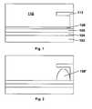
- Figure 1 of the accompanying drawingsis a schematic side elevation of a concealment member display of the present invention with the second fluid covering a large first area of a substrate;
- Figure 2is a schematic side elevation similar to Figure 1 but showing the second fluid confined to a smaller second area of the substrate.
- Figure 3is a top plan view of the substrate of a four-color color shifting display of the present invention.
- Figure 4is a schematic side elevation of a bistable dual colored fluid electro-wetting display of the present invention.
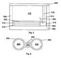
- Figure 5is schematic side elevation of a microcell display of the present invention.
- Figure 6is a top plan view of a second color shifting display of the present invention.
- Figure 7is a schematic side elevation of a conductive via display of the present invention.
- a microcell display of the inventionmight use a first fluid colored with pigment particles or nanoparticles in accordance with the pigment/nanoparticle aspect of the invention.
- the first (moving) fluidis typically an oil
- the second fluidis typically aqueous.
- oil and waterinstead of first and second fluids, but these terms “oil” and “water” should not be construed in a limitative sense.
- the present inventionprovides a concealment member display having a concealment member for concealing the oil when an electric field is applied; the present invention also provides a method for operating such a display.
- a specific concealment member display of the inventionis illustrated in Figures 1 and 2 of the accompanying drawings.
- the electro-wetting display(only a single pixel of which is illustrated) comprises a substrate 102 (typically colored white), a transparent first electrode 104, and a dielectric layer 106.
- a layer of a colored first fluid (oil)is spread over a large first area (illustrated as the whole) of the dielectric layer 106, and a transparent second fluid (water) 110 overlies the oil layer 108.
- the electro-wetting displayfurther comprises a concealment member 112 which has a first portion extending away from the dielectric layer 106 and a second portion extending parallel to the planar dielectric layer 106; the surface of the second portion of the concealment member 112 carries a second electrode (not shown).
- Figure 1shows the electro-wetting display with no field being applied between the two electrodes, so that a colored oil layer 108 is spread uniformly over the surface of the dielectric layer 106.
- the single pixel illustrateddisplays the color of the oil.
- Figure 2shows the display with a field applied between the two electrodes.
- the oil layeris no longer spread uniformly over the surface of the of the dielectric layer 106 but instead is gathered into the compact droplet 108' covering a second area lying beneath the concealment member 112, so that an observer viewing the display in the intended direction (namely from the opposed side of the concealment member 112 from the substrate 102, i.e., from above in Figures 1 and 2 ) sees primarily the white substrate 102, with the concealment member 112 concealing the oil droplet 108' from the observer.
- the contrast ratio of the pixelcan be altered by varying the color of the visible surface of the concealment member 112 (i.e., the surface remote from the dielectric layer 106). For example, making this visible surface white will increase the brightness of the white state of the pixel (as illustrated in Figure 2 ) although at some cost to the darkness of the dark state (shown in Figure 1 ). Alternatively, the maximum contrast ratio might be achieved by making the visible surface an intermediate gray shade.
- the second electrodebe located on the concealment member, so long as the second electrode is in electrical contact with the water 110.
- each pixel of the displaymay have a separate second electrode; instead, the display may use an electrode arrangement similar to that of conventional active matrix displays, with a common front electrode (shaped to appropriately direct the movement of the first fluid, as described below) extending across a large number of pixels and typically the whole display) but with individual first electrodes 104 for each pixel.
- the substratecould be transparent, so that the display acts as a light modulator.
- a colored filter or reflectorcould be disposed in any suitable location.
- Figure 3is a highly schematic top plan view of one pixel of the substrate of a four-color color shifting display of the present invention.
- the pixelis equilaterally triangular, and is composed of four equilaterally triangular sub-pixels, with the central sub-pixel being black (K) and the others red (R), green (G) and blue (B); obviously, cyan, yellow and magenta sub-pixels could be used in place of the red, green and blue ones if desired.
- This pixelis provided with four electrodes (not shown), one at each of the vertices of the triangular pixel and the fourth at its center.
- the electrodescould be provided on concealment members similar to that shown in Figures 1 and 2 , with the exposed surfaces of the concealment members colored to match the underlying portion of the pixel.
- the pixelis used in combination with a black colored oil, and functions in a manner very similar to the display shown in Figures 1 and 2 .
- the oilis spread uniformly over the entire pixel, which thus appears black throughout. If a voltage is applied using only the central electrode, the oil is gathered into the central black sub-pixel, leaving the red, green and blue sub-pixels exposed, so that the overall appearance of the pixel will be a "process white" (actually a gray).
- the inkwill cover the black and red sub-pixels and a cyan color will be displayed. It will readily be apparent that by applying voltages to one, two or three electrodes, a variety of colors can be displayed on the pixel.
- bistable electro-wetting displaysIt is also possible to produce bistable electro-wetting displays. Most prior art electro-wetting displays are only monostable because only the state in which no electric field is being applied is stable; the other state (similar to that shown in Figure 2 ) only persists as long as the field is applied.
- dual colored fluid electro-wetting displays of the present inventioncan be made having two states each of which is similar to that shown in Figure 1 .
- One pixel of one form of such a dual colored fluid bistable displayis illustrated in Figure 4 .
- This displaycomprises a substrate 102 (which, for reasons explained below, need not be colored), an electrode 104 (which need not be transparent), and a dielectric layer 106, all of which are, except as indicated, similar to the corresponding integers in Figure 1 .
- the displayfurther comprises a colored oil layer 108 and a colored aqueous layer 110', which has a color different from that of the oil layer 108.
- the display of Figure 4comprises a front transparent dielectric layer 114 and a transparent front electrode 116; in practice, it may be desirable to provide a front substrate (not shown) to provide mechanical support and protection for the display.
- the oil layer 108can be made to dewet from the dielectric layer 106, form a part-ellipsoidal droplet similar to the droplet 108' shown in Figure 2 , and thence (as the driving voltage is removed) wet the front transparent dielectric layer 114, thereby entering a second stable state, which is generally similar to that shown in Figure 4 except that the oil layer lies adjacent the front transparent dielectric layer 114.
- the pixeldisplays the color of the oil layer, which obscures the color of the aqueous layer 110'. It will readily be apparent that the pixel can be switched between these two stable states as often as desired.
- the displaysince a substantial voltage will have to be applied to the display to switch it between its two stable states, the display has a threshold for switching; such a threshold may enable such a display to be driven using a passive matrix approach instead of requiring the use of a more complicated active matrix approach.
- dyesare used to color the oil layer 108 and the aqueous layer 110' in the display of Figure 4 , it is important for long term stability of the display that these dyes not migrate between the two layers. In practice, this should not create great difficulties, since a variety of dyes are available which are water-soluble but not oil-soluble, or vice versa. However, it may be advantageous to employ pigment particles or nanoparticles rather than dyes as colorants. Such pigment particles or nanoparticles may be provided with coatings (see, for example, U.S. Published Patent Application No. 2002/0185378 ) to render them strongly hydrophilic or lipophilic so that they will not migrate between the oil and water layers.
- Figure 5 of the accompanying drawingsis a schematic side elevation, generally similar to that of Figure 4 , and showing a microcell electro-wetting display which operates in a manner generally similar to that of Figure 4 .
- Figure 5shows a single microcell of the display having a rear wall (second substrate) 502, side walls 504 and 506 and a front wall (first substrate) 508 through which the display is viewed.
- the microcellfurther comprises a rear transparent electrode 510, and a rear dielectric layer 512, which are similar to the corresponding integers shown in Figures 1 and 4 and are disposed adjacent the second substrate surface of the microcell.
- the microcellalso comprises a side (second) electrode 514 (which need not be transparent) disposed adjacent the sidewall surface, and an associated side dielectric layer 516.
- the electrodes 510 and 514are insulated from each other by an insulator block 518, from which a third electrode 520 emerges into an uncolored aqueous medium 110 which substantially fills the microcell.
- the microcellalso contains a colored oil phase 522.
- the first stable state of the microcell shown in Figure 5is similar to that of Figures 1 and 4 ; when no voltages are applied between the electrodes, the colored oil phase 522 wets the rear dielectric layer 512 so that an observer viewing the microcell through the front wall 508 sees the color of the oil phase 522 through the uncolored aqueous medium 110. However, upon sudden application of a voltage between the rear electrode 510 and the third electrode 520, the oil phase 522 will cease to wet the rear dielectric layer 512 and will form a droplet which will travel past the electrode 520 and end up in a second stable state in which it wets the side dielectric layer 516.
- a simple monochrome displaycan be provided by moving a black oil phase between a large white electrode and a small black one; obviously, when the black oil phase covers the white electrode, both the black and white electrodes appear black, while when the black oil phase is confined to the small black electrode, the overall appearance of the pixel is essentially white. More complex effects, including color, can be produced by using (for example) an oil phase having substantially the same color as a small electrode, while an adjacent larger electrode is of a complementary color. Thus, a color display might make use of individual pixels having the following oil/electrode combinations:
- the second color shifting display of the present invention shown in Figure 6may be useful.
- This displayis essentially dumb-bell shaped, with a dielectric surface having two circular portions 602 and 604 linked by a central, substantially rectangular "neck" portion 606.
- the display shown in Figure 6operates in the following manner.
- a colored oil phaseis disposed on the circular portion 602, with an aqueous phase overlying the colored oil phase and extending into contact with the rectangular electrode 612 and the circular portion 604.
- a voltageis applied to the electrode 608, thereby making this electrode hydrophilic, and no voltage is applied to the electrode 612, so that this electrode becomes hydrophobic. Accordingly, the oil phase moves from portion 602 to neck portion 606.
- a voltageis applied to electrode 612, while keeping the voltage applied to electrode 608, but no voltage is applied to the electrode 610. Accordingly, the oil phase moves from neck portion 606 to circular portion 604.
- the disposition of the oil phase on circular portion 604will typically be stable, so that once the oil phase is located on portion 604, no voltage need be applied to any of the electrodes.
- circular portions 602 and 604are shown as the same size in Figure 6 , these portions could of course vary in shape (for example, one portion could be elliptical rather than circular), size and/or color.
- one of the circular portionscould be provided with a concealment member, similar to concealment member 112 in Figure 1 , to obscure the oil phase present on that circular portion.
- FIG 7is a schematic side elevation of a conductive via electro-wetting display of the present invention.
- This displayuses an aqueous (and typically colored) medium as its working fluid.
- the display of Figure 7comprises a substrate 702 formed of a hydrophobic dielectric material.
- a very high K dielectricis preferred for this purpose, for example a suspension of a ceramic high K dielectric such as barium titanate in a polar polymer such as poly(vinylidene fluoride).
- a polar polymersuch as poly(vinylidene fluoride).
- the substrate 702could comprise a high K hydrophobic dielectric exposed surface layer on a base of a low K material, for example a polymer such as polyethylene or poly(ethylene terephthalate).
- a plurality of spaced conductive vias 704extend through the substrate 702, and terminate adjacent the exposed upper surface thereof.
- Each via 704is capped by a thin cap member 706 in the form of a hydrophilic coating covering the end of the conductive via 704 adjacent the exposed upper surface of the substrate 702.
- a larger numberwould typically be used, and the vias would be arranged in a two-dimensional array.
- aqueous working fluidrests upon the exposed surface of the substrate 702.
- the drop 708will not wet the hydrophobic surface of the substrate 702, but will "ball up” around the cap member 706 of one of the vias 704 (this is not the situation illustrated in Figure 7 ).
- the portion of the surface of the substrate 702 between these viasbecomes less hydrophobic, and consequently the drop 708 spreads out across the cap members of the two vias to which the voltage has been applied, and the intervening portion of the substrate 702, as illustrated in Figure 7 .
- the drop 708will be stable in the position shown in Figure 7 , i.e., the drop will remain in the same position even after removal of voltage from the two electrodes, since the drop is "pinned" at either end by the cap members 706 on the two vias.
- a voltagemay be applied to (say) the center and left vias 704. This renders the portion of the exposed surface of the substrate 702 between these vias less hydrophobic, and consequently the drop will flow on to the less hydrophobic portion of the surface, thus assuming the form 708' shown in Figure 7 .
- more elaborate manipulations of the aqueous fluidare possible, especially using two-dimensional arrays of vias.
- this inventionalso extends to the use of pigments and nanoparticles as coloring agents in electro-wetting displays.
- electro-wetting displayshave hitherto used dyes dissolved in the oil and/or aqueous phases, dyes in solution are notoriously susceptible to the long term effects of electromagnetic radiation, especially ultra-violet radiation, which tends to cause fading and/or discoloration of the dyes, and such effects may limit the operating lifetime of electro-wetting displays.
- Replacement of dissolved dyes with pigments or nanoparticlesprovides useful increases in the operating lifetime.
- pigments or nanoparticlesalso allows for control of the surface properties of the pigments or nanoparticles, for example, by the formation of charged or chargeable groups, or polymers, thereon (see, for example, U.S. Published Patent Application No. 2002/0185378 ).
Landscapes
- Physics & Mathematics (AREA)
- General Physics & Mathematics (AREA)
- Engineering & Computer Science (AREA)
- Theoretical Computer Science (AREA)
- Optics & Photonics (AREA)
- Computer Hardware Design (AREA)
- Electrochromic Elements, Electrophoresis, Or Variable Reflection Or Absorption Elements (AREA)
- Devices For Indicating Variable Information By Combining Individual Elements (AREA)
Abstract
Description
- This invention relates to electro-wetting displays.
- It has been known for more than a century that the interfacial tension between two immiscible media can be controlled by applying an electric potential across these media; see, for example,Lippmann, M.G., Ann. Chim. Phys., 5 ,494 (1875). It has also long been known that the mathematical relationship between the applied electric potential (V) and the resulting surface tension (γ) can be expressed in Lippmann's Equation:

- where γ0 is the surface tension of the solid-liquid interface at the potential zero charge (i.e., when there is no charge at the surface of the solid), and c is the capacitance per unit area, assuming that the charge layer can be modeled as a symmetric Helmholtz capacitor. So-called electro-osmotic and electro-capillary displays have also been developed; all these types of displays rely upon the change in wetting characteristics of a liquid in the presence of an electric field. See, for example,Sheridon, N.K., "Electrocapillary Imaging Devices for Display and Data Storage", Xerox Disclosure Journal 1979, 4, 385-386; and
U.S. Patents Nos. 5,956,005 ;5,808,593 ;5,757,345 ;5,731,792 ;5,659,330 ;4,569,575 ;6,603,444 ; and6,449,081 . A variety of displays using this principle have also been developed by Richard B. Fair and his co-workers at Duke University; see, for example, http://www.ee.duke.edu/Research/microfluidics. - More recently, it has been discovered that a thin dielectric layer between the electrode and the liquid in an electro-wetting apparatus (thereby forming a so-called "electro-wetting on dielectric" apparatus) can emulate the electric double layer present in conventional electro-wetting apparatus. The dielectric layer can block electron transfer while sustaining the high electric field at the interface that results in charge redistribution when a potential is applied. Using a hydrophobic dielectric and an aqueous liquid provides a large initial contact angle, and thus room for a large change in contact angle upon electro-wetting. Furthermore, by employing a dielectric layer between the liquid and electrode, virtually any kind of liquid can be used, regardless of the polarization of the interface; seeMoon, H., et al., "Low voltage electrowetting-on-dielectric", J. Appl. Phys, 2002, 92, 4080.
- Researchers at Philips Research Laboratories, Eindhoven, the Netherlands, have described an electro-wetting display which is stated to be capable of video rate applications; seeNature, 425, 383 (2003) and International Applications
WO 2004/068208 ;WO 2004/027489 ; andWO 03/071346 - This type of display has a number of problems. The display is not bistable, since the confinement of the oil to the small portion of the pixel only lasts as long as the field is applied. While this is not a serious disadvantage when the display is used continuously to display video, there are applications where a user may wish to pause a video and examine an individual frame and, especially in portable devices, it would be advantageous if the display could be made bistable so that such examination of individual frames could be done without continuous power drain on a battery. The visibility of the oil in a small portion of the pixel reduces the contrast ratio of the display. The use of a dye dissolved in the oil may give rise to long term problems since most dyes in solution are adversely affected by long term exposure to radiation, which typically causes fading of the dye. This may be a particular problem in a display which relies upon the use of differently-colored oils, which are unlikely to fade at the same rate, so that the colors displayed may drift with time.
- The present invention relates to various improvements in electro-wetting displays which can reduce or eliminate the aforementioned problems.
- In one aspect, this invention provides a display comprising:
- a substrate;
- a first fluid disposed adjacent the substrate, the first fluid absorbing at least one wavelength of light;
- a light-transmissive second fluid immiscible with the first fluid;
- at least one electrode for applying an electric field to the first fluid; and
- a concealment member spaced from the substrate and formed from a substantially opaque material,
- such that, in the absence of an electric field, the first fluid covers a first area of the substrate, but that upon application of an electric field to the first fluid by the at least one electrode, the first fluid moves to a second area smaller than the first area and substantially confined between the concealment member and the substrate, so that the concealment member substantially conceals the first fluid from an observer viewing the display from the opposed side of the concealment member from the substrate.
- The term "light-transmissive" is used herein to mean that the second fluid must transmit sufficient light to enable an observer, viewing the movement of the first fluid through the second fluid, to see this movement. (In the case of displays intended for machine reading at non-optical wavelengths, the term "light-transmissive" must of course be understood to mean transmissive of the wavelength(s) of electromagnetic radiation at which the display is read, and other terms used below referring to light should be construed accordingly.) Typically, the light-transmissive second fluid will be transparent, but we do not exclude the possibility that some color might be present in the second fluid to adjust the colors displayed. For example, many people prefer a "white" with a slightly blue hue over a strictly neutral white, so that, for example, in a display of the type described below with reference to
Figures 1 and 2 , in which the color change is from white to black, it may be advantageous to impart a slight blue color to render the white state slightly blue-white. - For convenience, this display may hereinafter be called the "concealment member display" of the present invention. In such a display, the substrate may comprise a dielectric surface adjacent the first fluid, and/or may comprise a colored or reflective layer. In one preferred form of such a display, the substrate has a substantially planar surface and the concealment member includes a substantially planar section extending substantially parallel to, but spaced from, the substantially planar surface of the substrate.
- In another aspect, this invention provides a display comprising:
- a substrate having at least first and second portions having first and second optical characteristics differing from one another;
- a first fluid, the first fluid absorbing at least one wavelength of light and having a third optical characteristic differing from at least one of the first and second optical characteristics;
- a light-transmissive second fluid immiscible with the first fluid; and
- a first electrode adjacent the first portion of the substrate and a second electrode adjacent the second portion of the substrate,
- such that by controlling the potentials applied to the first and second electrodes, the first fluid can be made to assume a first position, wherein the first fluid substantially covers the second portion of the substrate, leaving the first portion uncovered, and a second position, wherein the first fluid substantially covers the first portion of the substrate, leaving the second portion uncovered.
- For convenience, this display may hereinafter be called the "color shifting display" of the present invention. In such a display, the first fluid may be capable of assuming a third position in which it covers both the first and second portions of the display.
- In a color shifting display, the substrate may have more than two portions of differing colors. For example, the substrate may have a third portion having an optical characteristic differing from the first, second and third optical characteristics, and the display may further comprise a third electrode adjacent the third portion of the substrate, such that by controlling the potentials applied to the first, second and third electrodes, the first fluid can be made to assume a third position, wherein the first fluid substantially covers at least one of the first and second portions of the substrate, leaving the third portion uncovered. For example, the first, second and third portions of the substrate may be red, green and blue, or yellow, cyan and magenta in any arrangement. Further, the substrate may have a fourth portion having an optical characteristic differing from the first, second and third optical characteristics and from the optical characteristic of the third portion of the substrate, and the display may further comprise a fourth electrode adjacent the fourth portion of the substrate, such that by controlling the potentials applied to the first, second, third and fourth electrodes, the first fluid can be made to assume a fourth position, wherein the first fluid substantially covers at least one of the first, second and third portions of the substrate, leaving the fourth portion uncovered. For example, the first, second, third and fourth portions of the substrate may be red, green, blue and black, or yellow, cyan, magenta and black, in any arrangement.
- In a color shifting display of the invention typically the first and second (and third and fourth, if present) portions of the substrate will be coplanar. These portions may assume various geometric forms. For example, these portions may have substantially the form of equilateral triangles. Alternatively, the first and second portions may have substantially the form of circles, the substantially circular first and second portions being connected by a neck section having a width smaller than the diameter of each substantially circular portion. An electrode may be disposed on or adjacent this neck section.
- In another aspect, this invention provides a display comprising:
- a first substrate through which an observer can view the display, a second substrate spaced from the first substrate and at least one sidewall extending between the first and second substrates, the first and second substrates and the sidewall together defining a chamber having a first substrate surface, a second substrate surface and at least one sidewall surface;
- a first fluid disposed within the chamber, the first fluid absorbing at least one wavelength of light;
- a light-transmissive second fluid immiscible with the first fluid and disposed within the chamber;
- a first electrode disposed adjacent the second substrate surface of the chamber;
- a second electrode disposed adjacent a sidewall surface of the chamber; and
- a third electrode extending into the chamber and in electrical contact with the second fluid,
- such that, by controlling the potentials applied to the first, second and third electrodes, the first fluid can be made to assume a first position, wherein the first fluid lies adjacent the second substrate surface of the chamber, and a second position, wherein the first fluid lies adjacent a sidewall surface of the chamber.
- For convenience, this display may hereinafter be called the "microcell display" of the present invention. In such a display, the substrate may comprise a dielectric surface adjacent the first fluid, and/or may comprise a colored or reflective layer. The display may further comprise an insulator block disposed adjacent the junction between the second substrate surface and a sidewall surface of the chamber, with the third electrode passing through the insulator block.
- In another aspect, this invention provides a display comprising:
- a fluid;
- a substrate having an exposed surface resistant to wetting by the fluid;
- at least three conductive vias extending through the substrate and terminating adjacent the exposed surface thereof; and
- cap members covering the ends of the conductive vias adjacent the exposed surface, the cap members being formed of a material wetted by the fluid.
- For convenience, this display may hereinafter be called the "conductive via display" of the present invention. In such a display, the conductive vias may be arranged in a two-dimensional array. Also, the fluid may be aqueous, the exposed surface hydrophobic and the cap members formed of a hydrophilic material.
- In another aspect, this invention provides a display comprising:
- a substrate;
- a first fluid disposed adjacent the substrate, the first fluid absorbing at least one wavelength of light;
- a light-transmissive second fluid immiscible with the first fluid; and
- at least one electrode for applying an electric field to the first fluid,
- such that, in the absence of an electric field, the first fluid covers a first area of the substrate, but that upon application of an electric field to the first fluid by the at least one electrode, the first fluid moves to a second area smaller than the first area,
- wherein the first fluid is colored with pigment particles or nanoparticles.
- For convenience, this display may hereinafter be called the "pigment/nanoparticle display" of the present invention.
- Finally, this invention provides a display comprising:
- spaced first and second electrodes, the second electrode being light-transmissive;
- first and second fluids confined between the first and second electrodes, the first and second fluids being immiscible with each other, the first and second fluids being non-light-transmissive and having differing colors,
- the display having a first stable state wherein the first fluid lies adjacent the first electrode so that the color of the second fluid is visible to an observer viewing the display through the second electrode, and a second stable state wherein the first fluid lies adjacent the second electrode so that the color of the first fluid is visible to the observer.
- For convenience, this display may hereinafter be called the "dual colored fluid display" of the present invention. In such a display, the first fluid may comprise an oil and the second fluid be aqueous. The display may further comprise first and second dielectric layers disposed between the first and second electrodes respectively and the fluids.
Figure 1 of the accompanying drawings is a schematic side elevation of a concealment member display of the present invention with the second fluid covering a large first area of a substrate;Figure 2 is a schematic side elevation similar toFigure 1 but showing the second fluid confined to a smaller second area of the substrate.Figure 3 is a top plan view of the substrate of a four-color color shifting display of the present invention.Figure 4 is a schematic side elevation of a bistable dual colored fluid electro-wetting display of the present invention.Figure 5 is schematic side elevation of a microcell display of the present invention.Figure 6 is a top plan view of a second color shifting display of the present invention.Figure 7 is a schematic side elevation of a conductive via display of the present invention.- As already mentioned, this invention has several different aspects. These various aspects will be described separately below, but it should be understood that a single display may make use of multiple aspects of the invention. For example, a microcell display of the invention might use a first fluid colored with pigment particles or nanoparticles in accordance with the pigment/nanoparticle aspect of the invention.
- In the present displays, the first (moving) fluid is typically an oil, while the second fluid is typically aqueous. For ease of comprehension, the description below may use the terms "oil" and "water" instead of first and second fluids, but these terms "oil" and "water" should not be construed in a limitative sense.
- Firstly, as already mentioned, the present invention provides a concealment member display having a concealment member for concealing the oil when an electric field is applied; the present invention also provides a method for operating such a display. A specific concealment member display of the invention is illustrated in
Figures 1 and 2 of the accompanying drawings. As shown inFigure 1 , the electro-wetting display (only a single pixel of which is illustrated) comprises a substrate 102 (typically colored white), a transparentfirst electrode 104, and adielectric layer 106. A layer of a colored first fluid (oil) is spread over a large first area (illustrated as the whole) of thedielectric layer 106, and a transparent second fluid (water) 110 overlies theoil layer 108. The electro-wetting display further comprises aconcealment member 112 which has a first portion extending away from thedielectric layer 106 and a second portion extending parallel to theplanar dielectric layer 106; the surface of the second portion of theconcealment member 112 carries a second electrode (not shown). Figure 1 shows the electro-wetting display with no field being applied between the two electrodes, so that acolored oil layer 108 is spread uniformly over the surface of thedielectric layer 106. Thus, the single pixel illustrated displays the color of the oil.Figure 2 shows the display with a field applied between the two electrodes. The oil layer is no longer spread uniformly over the surface of the of thedielectric layer 106 but instead is gathered into the compact droplet 108' covering a second area lying beneath theconcealment member 112, so that an observer viewing the display in the intended direction (namely from the opposed side of theconcealment member 112 from thesubstrate 102, i.e., from above inFigures 1 and 2 ) sees primarily thewhite substrate 102, with theconcealment member 112 concealing the oil droplet 108' from the observer.- It will be apparent that the contrast ratio of the pixel can be altered by varying the color of the visible surface of the concealment member 112 (i.e., the surface remote from the dielectric layer 106). For example, making this visible surface white will increase the brightness of the white state of the pixel (as illustrated in
Figure 2 ) although at some cost to the darkness of the dark state (shown inFigure 1 ). Alternatively, the maximum contrast ratio might be achieved by making the visible surface an intermediate gray shade. - Numerous variations of the display shown in
Figures 1 and 2 are possible. For example, it is not necessary that the second electrode be located on the concealment member, so long as the second electrode is in electrical contact with thewater 110. Indeed, it is not necessary that each pixel of the display have a separate second electrode; instead, the display may use an electrode arrangement similar to that of conventional active matrix displays, with a common front electrode (shaped to appropriately direct the movement of the first fluid, as described below) extending across a large number of pixels and typically the whole display) but with individualfirst electrodes 104 for each pixel. Also, it is not necessary that one optical state of the display show the color of the substrate. For example, the substrate could be transparent, so that the display acts as a light modulator. Alternatively, a colored filter or reflector could be disposed in any suitable location. Figure 3 is a highly schematic top plan view of one pixel of the substrate of a four-color color shifting display of the present invention. As will be seen from this Figure, the pixel is equilaterally triangular, and is composed of four equilaterally triangular sub-pixels, with the central sub-pixel being black (K) and the others red (R), green (G) and blue (B); obviously, cyan, yellow and magenta sub-pixels could be used in place of the red, green and blue ones if desired. This pixel is provided with four electrodes (not shown), one at each of the vertices of the triangular pixel and the fourth at its center. (If desired, the electrodes could be provided on concealment members similar to that shown inFigures 1 and 2 , with the exposed surfaces of the concealment members colored to match the underlying portion of the pixel.) The pixel is used in combination with a black colored oil, and functions in a manner very similar to the display shown inFigures 1 and 2 . When no field is applied by any of the electrodes, the oil is spread uniformly over the entire pixel, which thus appears black throughout. If a voltage is applied using only the central electrode, the oil is gathered into the central black sub-pixel, leaving the red, green and blue sub-pixels exposed, so that the overall appearance of the pixel will be a "process white" (actually a gray). If, for example, a voltage is applied using both the central electrode and the electrode adjacent the red sub-pixel, the ink will cover the black and red sub-pixels and a cyan color will be displayed. It will readily be apparent that by applying voltages to one, two or three electrodes, a variety of colors can be displayed on the pixel.- It is also possible to produce bistable electro-wetting displays. Most prior art electro-wetting displays are only monostable because only the state in which no electric field is being applied is stable; the other state (similar to that shown in
Figure 2 ) only persists as long as the field is applied. However, dual colored fluid electro-wetting displays of the present invention can be made having two states each of which is similar to that shown inFigure 1 . One pixel of one form of such a dual colored fluid bistable display is illustrated inFigure 4 . This display comprises a substrate 102 (which, for reasons explained below, need not be colored), an electrode 104 (which need not be transparent), and adielectric layer 106, all of which are, except as indicated, similar to the corresponding integers inFigure 1 . The display further comprises acolored oil layer 108 and acolored aqueous layer 110', which has a color different from that of theoil layer 108. There is no concealment member, but instead the display ofFigure 4 comprises a front transparentdielectric layer 114 and a transparentfront electrode 116; in practice, it may be desirable to provide a front substrate (not shown) to provide mechanical support and protection for the display. - In the condition shown in
Figure 4 , which is equivalent to that shown inFigure 1 , with theoil layer 108 spread uniformly over thedielectric layer 106, the pixel displays (to an observer viewing the display through theelectrode 116 anddielectric layer 114, i.e., from above inFigure 4 ) the color of the aqueous layer 110', which obscures the color of theoil layer 108. However, by applying suddenly a voltage between theelectrode 104 and an electrode (not shown) in contact with the aqueous layer 110', theoil layer 108 can be made to dewet from thedielectric layer 106, form a part-ellipsoidal droplet similar to the droplet 108' shown inFigure 2 , and thence (as the driving voltage is removed) wet the front transparentdielectric layer 114, thereby entering a second stable state, which is generally similar to that shown inFigure 4 except that the oil layer lies adjacent the front transparentdielectric layer 114. In this second state stable, the pixel displays the color of the oil layer, which obscures the color of the aqueous layer 110'. It will readily be apparent that the pixel can be switched between these two stable states as often as desired. Furthermore, since a substantial voltage will have to be applied to the display to switch it between its two stable states, the display has a threshold for switching; such a threshold may enable such a display to be driven using a passive matrix approach instead of requiring the use of a more complicated active matrix approach. - If dyes are used to color the
oil layer 108 and the aqueous layer 110' in the display ofFigure 4 , it is important for long term stability of the display that these dyes not migrate between the two layers. In practice, this should not create great difficulties, since a variety of dyes are available which are water-soluble but not oil-soluble, orvice versa. However, it may be advantageous to employ pigment particles or nanoparticles rather than dyes as colorants. Such pigment particles or nanoparticles may be provided with coatings (see, for example,U.S. Published Patent Application No. 2002/0185378 ) to render them strongly hydrophilic or lipophilic so that they will not migrate between the oil and water layers. Figure 5 of the accompanying drawings is a schematic side elevation, generally similar to that ofFigure 4 , and showing a microcell electro-wetting display which operates in a manner generally similar to that ofFigure 4 .Figure 5 shows a single microcell of the display having a rear wall (second substrate) 502,side walls transparent electrode 510, and arear dielectric layer 512, which are similar to the corresponding integers shown inFigures 1 and4 and are disposed adjacent the second substrate surface of the microcell. However, the microcell also comprises a side (second) electrode 514 (which need not be transparent) disposed adjacent the sidewall surface, and an associated sidedielectric layer 516. Theelectrodes insulator block 518, from which athird electrode 520 emerges into an uncoloredaqueous medium 110 which substantially fills the microcell. The microcell also contains acolored oil phase 522.- The first stable state of the microcell shown in
Figure 5 is similar to that ofFigures 1 and4 ; when no voltages are applied between the electrodes, thecolored oil phase 522 wets therear dielectric layer 512 so that an observer viewing the microcell through thefront wall 508 sees the color of theoil phase 522 through the uncoloredaqueous medium 110. However, upon sudden application of a voltage between therear electrode 510 and thethird electrode 520, theoil phase 522 will cease to wet therear dielectric layer 512 and will form a droplet which will travel past theelectrode 520 and end up in a second stable state in which it wets theside dielectric layer 516. In this second stable state, an observer viewing the microcell through thefront wall 508 sees the color (if any) of therear electrode 510 or therear dielectric layer 512, either of which may be colored (theoil phase 522 lying adjacent theside dielectric layer 516 occupies only a small proportion of the cross-section of the microcell and is essentially invisible to the observer). Alternatively, both therear electrode 510 and therear dielectric layer 512 may be uncolored, and a colored backing or reflector may be provided behind the microcell, so that the microcell can operate in so-called "shutter mode" cf.U.S. Patents Nos. 6,130,774 and6,172,798 . - It will be appreciated that, in addition to the embodiments described above with reference to
Figures 1 to 5 , numerous other types of color electro-wetting displays can be produced using colored oil phases which are moved to cover electrodes having other colors and possibly differing in area. It is known that liquid droplets can be moved by electric fields between adjacent electrodes lying in the same plane by applying voltage to an electrode adjacent to one on which an oil phase is resting, thereby causing the oil phase to move to the electrode to which the voltage is applied. Such movement can of course be reversed. By using electrodes differing in color and optionally size, and colored oil phases, a variety of effects can be produced. A simple monochrome display can be provided by moving a black oil phase between a large white electrode and a small black one; obviously, when the black oil phase covers the white electrode, both the black and white electrodes appear black, while when the black oil phase is confined to the small black electrode, the overall appearance of the pixel is essentially white. More complex effects, including color, can be produced by using (for example) an oil phase having substantially the same color as a small electrode, while an adjacent larger electrode is of a complementary color. Thus, a color display might make use of individual pixels having the following oil/electrode combinations: - red oil/small red electrode/large cyan electrode;
- green oil/small green electrode/large magenta electrode; and
- blue oil/small blue electrode/large yellow electrode.
- In such displays, the second color shifting display of the present invention shown in
Figure 6 may be useful. This display is essentially dumb-bell shaped, with a dielectric surface having twocircular portions portion 606. There are three independently controllable electrodes, namely twocircular electrodes circular portions rectangular electrode 612 located in the center of theneck portion 606. - The display shown in
Figure 6 operates in the following manner. Suppose a colored oil phase is disposed on thecircular portion 602, with an aqueous phase overlying the colored oil phase and extending into contact with therectangular electrode 612 and thecircular portion 604. If it is desired to move the oil phase to occupy thecircular portion 604, a voltage is applied to theelectrode 608, thereby making this electrode hydrophilic, and no voltage is applied to theelectrode 612, so that this electrode becomes hydrophobic. Accordingly, the oil phase moves fromportion 602 toneck portion 606. Next, a voltage is applied toelectrode 612, while keeping the voltage applied toelectrode 608, but no voltage is applied to theelectrode 610. Accordingly, the oil phase moves fromneck portion 606 tocircular portion 604. The disposition of the oil phase oncircular portion 604 will typically be stable, so that once the oil phase is located onportion 604, no voltage need be applied to any of the electrodes. - Although the
circular portions Figure 6 , these portions could of course vary in shape (for example, one portion could be elliptical rather than circular), size and/or color. In addition, one of the circular portions could be provided with a concealment member, similar toconcealment member 112 inFigure 1 , to obscure the oil phase present on that circular portion. Figure 7 is a schematic side elevation of a conductive via electro-wetting display of the present invention. This display uses an aqueous (and typically colored) medium as its working fluid. The display ofFigure 7 comprises asubstrate 702 formed of a hydrophobic dielectric material. A very high K dielectric is preferred for this purpose, for example a suspension of a ceramic high K dielectric such as barium titanate in a polar polymer such as poly(vinylidene fluoride). For reasons which will appear below, provided that theentire substrate 702 is insulating, only the properties of the exposed upper surface (as illustrated inFigure 7 ) of thesubstrate 702 affect the operation of the display. Thus, thesubstrate 702 could comprise a high K hydrophobic dielectric exposed surface layer on a base of a low K material, for example a polymer such as polyethylene or poly(ethylene terephthalate).- A plurality of spaced
conductive vias 704 extend through thesubstrate 702, and terminate adjacent the exposed upper surface thereof. Each via 704 is capped by athin cap member 706 in the form of a hydrophilic coating covering the end of the conductive via 704 adjacent the exposed upper surface of thesubstrate 702. Although only threevias 704 arranged in a line are shown inFigure 7 , in practice a larger number would typically be used, and the vias would be arranged in a two-dimensional array. - An aqueous working fluid, illustrated as a
drop 708, rests upon the exposed surface of thesubstrate 702. In the absence of any voltage on any of thevias 704, thedrop 708 will not wet the hydrophobic surface of thesubstrate 702, but will "ball up" around thecap member 706 of one of the vias 704 (this is not the situation illustrated inFigure 7 ). However, by applying voltage to two adjacent vias 704 (say the center and right vias inFigure 7 ), the portion of the surface of thesubstrate 702 between these vias becomes less hydrophobic, and consequently thedrop 708 spreads out across the cap members of the two vias to which the voltage has been applied, and the intervening portion of thesubstrate 702, as illustrated inFigure 7 . Provided the characteristics of thecap members 706 and the exposed surface of thesubstrate 702 are chosen appropriately, thedrop 708 will be stable in the position shown inFigure 7 , i.e., the drop will remain in the same position even after removal of voltage from the two electrodes, since the drop is "pinned" at either end by thecap members 706 on the two vias. - To move the
drop 708 to a different position, a voltage may be applied to (say) the center and leftvias 704. This renders the portion of the exposed surface of thesubstrate 702 between these vias less hydrophobic, and consequently the drop will flow on to the less hydrophobic portion of the surface, thus assuming the form 708' shown inFigure 7 . Obviously, more elaborate manipulations of the aqueous fluid are possible, especially using two-dimensional arrays of vias. - As already indicated, this invention also extends to the use of pigments and nanoparticles as coloring agents in electro-wetting displays. Although electro-wetting displays have hitherto used dyes dissolved in the oil and/or aqueous phases, dyes in solution are notoriously susceptible to the long term effects of electromagnetic radiation, especially ultra-violet radiation, which tends to cause fading and/or discoloration of the dyes, and such effects may limit the operating lifetime of electro-wetting displays. Replacement of dissolved dyes with pigments or nanoparticles provides useful increases in the operating lifetime. The use of pigments or nanoparticles also allows for control of the surface properties of the pigments or nanoparticles, for example, by the formation of charged or chargeable groups, or polymers, thereon (see, for example,
U.S. Published Patent Application No. 2002/0185378 ).

Claims (15)
- A display comprising:spaced first (104) and second (116) electrodes, the second electrode (116) being light-transmissive; andfirst (108) and second (110') fluids confined between the first and second electrodes (104, 116), the first and second fluids (108, 110') being immiscible with each other,the display beingcharacterized in that the first and second fluids (108, 110') are non-light-transmissive and have differing colors,the display having a first stable state wherein the first fluid (108) lies adjacent the first electrode (104) so that the color of the second fluid (110') is visible to an observer viewing the display through the second electrode (116), and a second stable state, wherein the first fluid (108) lies adjacent the second electrode (116) so that the color of the first fluid (108) is visible to the observer.
- A display according to claim 1 further comprising first (106) and second (114) dielectric layers disposed between the first (104) and second (116) electrodes respectively and the fluids (108, 110').
- A display comprising:a substrate;a first fluid disposed adjacent the substrate, the first fluid absorbing at least one wavelength of light;a light-transmissive second fluid immiscible with the first fluid;at least one electrode for applying an electric field to the first fluid;the display beingcharacterized in that the substrate has at least first (R; 602) and second (G; 604) portions having first and second optical characteristics differing from one another;the first fluid has a third optical characteristic differing from at least one of the first and second optical characteristics;the display comprising a first electrode adjacent the first portion (R; 602) of the substrate and a second electrode adjacent the second portion (G; 604) of the substrate,such that .by controlling the potentials applied to the first and second electrodes, the first fluid can be made to assume a first position, wherein the first fluid substantially covers the second portion (G; 604) of the substrate, leaving the first portion (R; 602) uncovered, and a second position, wherein the first fluid substantially covers the first portion (R; 602) of the substrate, leaving the second portion (G; 604) uncovered.
- A display according to claim 3 wherein the first fluid can be made to assume a third position wherein it covers both the first and second portions (R, G) of the substrate.
- A display according to claim 3 wherein the substrate has a third portion (B) having an optical characteristic differing from the first, second and third optical characteristics, the display further comprising a third electrode adjacent the third portion (B) of the substrate, such that by controlling the potentials applied to the first, second and third electrodes, the first fluid can be made to assume a third position, wherein the first fluid substantially covers at least one of the first and second portions (R, G) of the substrate, leaving the third portion (B) uncovered.
- A display according to claim 5 wherein the substrate has a fourth portion (K) having an optical characteristic differing from the first, second and third optical characteristics and from the optical characteristic of the third portion (B) of the substrate, the display further comprising a fourth electrode adjacent the fourth portion (K) of the substrate, such that, by controlling the potentials applied to the first, second, third and fourth electrodes, the first fluid can be made to assume a fourth position, wherein the first fluid substantially covers at least one of the first, second and third portions (R, G, B) of the substrate, leaving the fourth portion (K) uncovered.
- A display according to claim 3 wherein the first and second portions (R, G) of the substrate have substantially the form of equilateral triangles.
- A display according to claim 3 wherein the first and second portions (602, 604) of the substrate have substantially the form of circles, the substantially circular first and second portions (602, 604) being connected by a neck section (606) having a width smaller than the diameter of each substantially circular portion (602, 604).
- A display according to claim 8 wherein an electrode (612) is disposed on or adjacent the neck section (606).
- A display comprising:a first substrate (508) through which an observer can view the display, a second substrate (502) spaced from the first substrate (508), and at least one sidewall (504, 506) extending between the first and second substrates (502, 508), the first and second substrates (502, 508) and the sidewall (504, 506) together defining a chamber having a first substrate surface, a second substrate surface and at least one sidewall surface;a first fluid (522) disposed within the chamber;a light-transmissive second fluid (110) immiscible with the first fluid (522) and disposed within the chamber; anda first electrode (510) disposed adjacent the second substrate surface of the chamber;the display beingcharacterized in that:the first fluid (522) absorbs at least one wavelength of light;a second electrode (514) is disposed adjacent a sidewall surface of the chamber; anda third electrode (520) extends into the chamber and is in electrical contact with the second fluid (110),such that, by controlling the potentials applied to the first, second and third electrodes (510, 514, 520), the first fluid (522) can be made to assume a first position, wherein the first fluid (522) lies adjacent the second substrate surface of the chamber, and a second position, wherein the first fluid (522) lies adjacent a sidewall surface of the chamber.
- A display according to claim 10 wherein the second substrate (502) comprises a dielectric surface layer (512) adjacent the first fluid (522).
- A display according to claim 10 wherein the second substrate (502) comprises a colored or reflective layer.
- A display according to claim 10 further comprising an insulator block (518) disposed adjacent the junction between the second substrate surface and a sidewall surface of the chamber, wherein the third electrode (520) passes through the insulator block (518).
- A displaycharacterized by:a fluid (708);a substrate (702) having an exposed surface resistant to wetting by the fluid (708);at least three conductive vias (704) extending through the substrate (702) and terminating adjacent the exposed surface thereof; andcap members (706) covering the ends of the conductive vias (704) adjacent the exposed surface, the cap members (706) being formed of a material wetted by the fluid (708).
- A display comprising:a substrate;a first fluid disposed adjacent the substrate, the first fluid absorbing at least one wavelength of light;a light-transmissive second fluid immiscible with the first fluid; andat least one electrode for applying an electric field to the first fluid,such that, in the absence of an electric field, the first fluid covers a first area of the substrate, but that upon application of an electric field to the first fluid by the at least one electrode, the first fluid moves to a second area smaller than the first area,the display beingcharacterized in that the first fluid is colored with pigment particles or nanoparticles.
Applications Claiming Priority (3)
| Application Number | Priority Date | Filing Date | Title |
|---|---|---|---|
| US48148203P | 2003-10-08 | 2003-10-08 | |
| EP04794240AEP1671304B1 (en) | 2003-10-08 | 2004-10-06 | Electro-wetting displays |
| PCT/US2004/032828WO2005038764A1 (en) | 2003-10-08 | 2004-10-06 | Electro-wetting displays |
Related Parent Applications (1)
| Application Number | Title | Priority Date | Filing Date |
|---|---|---|---|
| EP04794240ADivisionEP1671304B1 (en) | 2003-10-08 | 2004-10-06 | Electro-wetting displays |
Publications (3)
| Publication Number | Publication Date |
|---|---|
| EP1967888A2true EP1967888A2 (en) | 2008-09-10 |
| EP1967888A3 EP1967888A3 (en) | 2009-01-14 |
| EP1967888B1 EP1967888B1 (en) | 2018-09-19 |
Family
ID=34465054
Family Applications (2)
| Application Number | Title | Priority Date | Filing Date |
|---|---|---|---|
| EP04794240AExpired - LifetimeEP1671304B1 (en) | 2003-10-08 | 2004-10-06 | Electro-wetting displays |
| EP08005744.1AExpired - LifetimeEP1967888B1 (en) | 2003-10-08 | 2004-10-06 | Electro-wetting displays |
Family Applications Before (1)
| Application Number | Title | Priority Date | Filing Date |
|---|---|---|---|
| EP04794240AExpired - LifetimeEP1671304B1 (en) | 2003-10-08 | 2004-10-06 | Electro-wetting displays |
Country Status (7)
| Country | Link |
|---|---|
| US (1) | US7420549B2 (en) |
| EP (2) | EP1671304B1 (en) |
| JP (6) | JP4739218B2 (en) |
| CN (4) | CN101930118B (en) |
| AT (1) | ATE405916T1 (en) |
| DE (1) | DE602004016017D1 (en) |
| WO (1) | WO2005038764A1 (en) |
Cited By (2)
| Publication number | Priority date | Publication date | Assignee | Title |
|---|---|---|---|---|
| WO2010104392A1 (en)* | 2009-03-12 | 2010-09-16 | Polymer Vision Limited | Display apparatus comprising electrofluidic cells |
| WO2014149944A1 (en)* | 2013-03-15 | 2014-09-25 | Pixtronix, Inc. | Systems and methods for microbubble generation in a liquid-filled display |
Families Citing this family (383)
| Publication number | Priority date | Publication date | Assignee | Title |
|---|---|---|---|---|
| US7327511B2 (en) | 2004-03-23 | 2008-02-05 | E Ink Corporation | Light modulators |
| US7999787B2 (en) | 1995-07-20 | 2011-08-16 | E Ink Corporation | Methods for driving electrophoretic displays using dielectrophoretic forces |
| US7848006B2 (en) | 1995-07-20 | 2010-12-07 | E Ink Corporation | Electrophoretic displays with controlled amounts of pigment |
| US7583251B2 (en) | 1995-07-20 | 2009-09-01 | E Ink Corporation | Dielectrophoretic displays |
| US7411719B2 (en) | 1995-07-20 | 2008-08-12 | E Ink Corporation | Electrophoretic medium and process for the production thereof |
| US8139050B2 (en) | 1995-07-20 | 2012-03-20 | E Ink Corporation | Addressing schemes for electronic displays |
| US8040594B2 (en) | 1997-08-28 | 2011-10-18 | E Ink Corporation | Multi-color electrophoretic displays |
| DE69920228T2 (en) | 1998-07-08 | 2005-01-27 | E-Ink Corp., Cambridge | METHOD FOR IMPROVING COLOR REPRODUCTION IN ELECTROPHORETIC DEVICES USING MICROCAPSULES |
| US7119759B2 (en) | 1999-05-03 | 2006-10-10 | E Ink Corporation | Machine-readable displays |
| US8115729B2 (en) | 1999-05-03 | 2012-02-14 | E Ink Corporation | Electrophoretic display element with filler particles |
| US8009348B2 (en) | 1999-05-03 | 2011-08-30 | E Ink Corporation | Machine-readable displays |
| US6924792B1 (en) | 2000-03-10 | 2005-08-02 | Richard V. Jessop | Electrowetting and electrostatic screen display systems, colour displays and transmission means |
| AU2002250304A1 (en) | 2001-03-13 | 2002-09-24 | E Ink Corporation | Apparatus for displaying drawings |
| US7679814B2 (en) | 2001-04-02 | 2010-03-16 | E Ink Corporation | Materials for use in electrophoretic displays |
| US20050156340A1 (en) | 2004-01-20 | 2005-07-21 | E Ink Corporation | Preparation of capsules |
| US8390918B2 (en) | 2001-04-02 | 2013-03-05 | E Ink Corporation | Electrophoretic displays with controlled amounts of pigment |
| US7230750B2 (en) | 2001-05-15 | 2007-06-12 | E Ink Corporation | Electrophoretic media and processes for the production thereof |
| US7535624B2 (en) | 2001-07-09 | 2009-05-19 | E Ink Corporation | Electro-optic display and materials for use therein |
| US8593396B2 (en) | 2001-11-20 | 2013-11-26 | E Ink Corporation | Methods and apparatus for driving electro-optic displays |
| US9530363B2 (en) | 2001-11-20 | 2016-12-27 | E Ink Corporation | Methods and apparatus for driving electro-optic displays |
| US8558783B2 (en)* | 2001-11-20 | 2013-10-15 | E Ink Corporation | Electro-optic displays with reduced remnant voltage |
| US8125501B2 (en) | 2001-11-20 | 2012-02-28 | E Ink Corporation | Voltage modulated driver circuits for electro-optic displays |
| US7952557B2 (en) | 2001-11-20 | 2011-05-31 | E Ink Corporation | Methods and apparatus for driving electro-optic displays |
| CN1633622A (en)* | 2002-02-19 | 2005-06-29 | 皇家飞利浦电子股份有限公司 | display device |
| US7223672B2 (en) | 2002-04-24 | 2007-05-29 | E Ink Corporation | Processes for forming backplanes for electro-optic displays |
| US7190008B2 (en) | 2002-04-24 | 2007-03-13 | E Ink Corporation | Electro-optic displays, and components for use therein |
| US7583427B2 (en) | 2002-06-10 | 2009-09-01 | E Ink Corporation | Components and methods for use in electro-optic displays |
| US8049947B2 (en) | 2002-06-10 | 2011-11-01 | E Ink Corporation | Components and methods for use in electro-optic displays |
| US8363299B2 (en) | 2002-06-10 | 2013-01-29 | E Ink Corporation | Electro-optic displays, and processes for the production thereof |
| US7554712B2 (en) | 2005-06-23 | 2009-06-30 | E Ink Corporation | Edge seals for, and processes for assembly of, electro-optic displays |
| US7843621B2 (en) | 2002-06-10 | 2010-11-30 | E Ink Corporation | Components and testing methods for use in the production of electro-optic displays |
| US7649674B2 (en) | 2002-06-10 | 2010-01-19 | E Ink Corporation | Electro-optic display with edge seal |
| US9470950B2 (en) | 2002-06-10 | 2016-10-18 | E Ink Corporation | Electro-optic displays, and processes for the production thereof |
| US7110164B2 (en) | 2002-06-10 | 2006-09-19 | E Ink Corporation | Electro-optic displays, and processes for the production thereof |
| US20080024482A1 (en) | 2002-06-13 | 2008-01-31 | E Ink Corporation | Methods for driving electro-optic displays |
| EP3056941B1 (en) | 2002-09-03 | 2019-01-09 | E Ink Corporation | Electro-phoretic medium |
| US7839564B2 (en) | 2002-09-03 | 2010-11-23 | E Ink Corporation | Components and methods for use in electro-optic displays |
| US20130063333A1 (en) | 2002-10-16 | 2013-03-14 | E Ink Corporation | Electrophoretic displays |
| US7910175B2 (en) | 2003-03-25 | 2011-03-22 | E Ink Corporation | Processes for the production of electrophoretic displays |
| US10726798B2 (en) | 2003-03-31 | 2020-07-28 | E Ink Corporation | Methods for operating electro-optic displays |
| WO2004104671A1 (en)* | 2003-05-22 | 2004-12-02 | Koninklijke Philips Electronics N.V. | Display device |
| US8174490B2 (en) | 2003-06-30 | 2012-05-08 | E Ink Corporation | Methods for driving electrophoretic displays |
| US7672040B2 (en) | 2003-11-05 | 2010-03-02 | E Ink Corporation | Electro-optic displays, and materials for use therein |
| US7551346B2 (en) | 2003-11-05 | 2009-06-23 | E Ink Corporation | Electro-optic displays, and materials for use therein |
| US20110164301A1 (en) | 2003-11-05 | 2011-07-07 | E Ink Corporation | Electro-optic displays, and materials for use therein |
| EP2487674B1 (en) | 2003-11-05 | 2018-02-21 | E Ink Corporation | Electro-optic displays |
| US8177942B2 (en) | 2003-11-05 | 2012-05-15 | E Ink Corporation | Electro-optic displays, and materials for use therein |
| US7206119B2 (en) | 2003-12-31 | 2007-04-17 | E Ink Corporation | Electro-optic displays, and method for driving same |
| US7075703B2 (en) | 2004-01-16 | 2006-07-11 | E Ink Corporation | Process for sealing electro-optic displays |
| US7388572B2 (en) | 2004-02-27 | 2008-06-17 | E Ink Corporation | Backplanes for electro-optic displays |
| US7492339B2 (en) | 2004-03-26 | 2009-02-17 | E Ink Corporation | Methods for driving bistable electro-optic displays |
| EP1761819A1 (en)* | 2004-06-23 | 2007-03-14 | Koninklijke Philips Electronics N.V. | Bi-stable electrowetting optical element and driving method therefore |
| CN100557474C (en) | 2004-07-27 | 2009-11-04 | 伊英克公司 | Electro-optic display |
| US20080136774A1 (en) | 2004-07-27 | 2008-06-12 | E Ink Corporation | Methods for driving electrophoretic displays using dielectrophoretic forces |
| US11250794B2 (en) | 2004-07-27 | 2022-02-15 | E Ink Corporation | Methods for driving electrophoretic displays using dielectrophoretic forces |
| US7453445B2 (en) | 2004-08-13 | 2008-11-18 | E Ink Corproation | Methods for driving electro-optic displays |
| JP2008520001A (en)* | 2004-11-12 | 2008-06-12 | コーニンクレッカ フィリップス エレクトロニクス エヌ ヴィ | High brightness full color reflective display |
| WO2006081305A2 (en) | 2005-01-26 | 2006-08-03 | E Ink Corporation | Electrophoretic displays using gaseous fluids |
| JP5042865B2 (en)* | 2005-02-28 | 2012-10-03 | サムスン エルシーディ ネザーランド アールアンドディ センター ビー ヴィ | Display device |
| WO2006104182A1 (en)* | 2005-03-29 | 2006-10-05 | Sharp Kabushiki Kaisha | Display element and electric device using the same |
| KR101129435B1 (en)* | 2005-06-15 | 2012-03-27 | 삼성전자주식회사 | Electrowetting display panel and manufacturing method thereof |
| US20090079689A1 (en)* | 2005-07-14 | 2009-03-26 | Akio Miyata | Display Device And Electric Apparatus Using The Same |
| US20070075922A1 (en)* | 2005-09-28 | 2007-04-05 | Jessop Richard V | Electronic display systems |
| EP1938299A4 (en) | 2005-10-18 | 2010-11-24 | E Ink Corp | Components for electro-optic displays |
| US20080043318A1 (en) | 2005-10-18 | 2008-02-21 | E Ink Corporation | Color electro-optic displays, and processes for the production thereof |
| KR100646810B1 (en)* | 2005-11-30 | 2006-11-23 | 이미지랩(주) | Emissive electrowetting display device |
| KR101287203B1 (en)* | 2005-12-28 | 2013-07-16 | 엘지디스플레이 주식회사 | Flexible Display |
| KR101287200B1 (en)* | 2005-12-28 | 2013-07-16 | 엘지디스플레이 주식회사 | Flexible Display |
| TWI350793B (en) | 2006-03-08 | 2011-10-21 | E Ink Corp | Methods for production of electro-optic displays |
| US8390301B2 (en) | 2006-03-08 | 2013-03-05 | E Ink Corporation | Electro-optic displays, and materials and methods for production thereof |
| US7843624B2 (en) | 2006-03-08 | 2010-11-30 | E Ink Corporation | Electro-optic displays, and materials and methods for production thereof |
| US8610988B2 (en) | 2006-03-09 | 2013-12-17 | E Ink Corporation | Electro-optic display with edge seal |
| US7952790B2 (en) | 2006-03-22 | 2011-05-31 | E Ink Corporation | Electro-optic media produced using ink jet printing |
| WO2007113637A1 (en)* | 2006-03-31 | 2007-10-11 | Varioptic | Multi-phase liquid composition and optical lens driven by electrowetting |
| GB0611134D0 (en)* | 2006-06-06 | 2006-07-19 | Liquavista Bv | Optical apparatus |
| GB0611125D0 (en) | 2006-06-06 | 2006-07-19 | Liquavista Bv | Transflective electrowetting display device |
| US7903319B2 (en) | 2006-07-11 | 2011-03-08 | E Ink Corporation | Electrophoretic medium and display with improved image stability |
| US8018640B2 (en) | 2006-07-13 | 2011-09-13 | E Ink Corporation | Particles for use in electrophoretic displays |
| US7492497B2 (en) | 2006-08-02 | 2009-02-17 | E Ink Corporation | Multi-layer light modulator |
| KR100723431B1 (en)* | 2006-09-11 | 2007-05-30 | 삼성전자주식회사 | Electro-wetting oil display element and method for controlling voltage of electrowetting oil display element |
| EP2487540A1 (en) | 2006-09-18 | 2012-08-15 | E-Ink Corporation | Color electro-optic displays |
| US7477444B2 (en) | 2006-09-22 | 2009-01-13 | E Ink Corporation & Air Products And Chemical, Inc. | Electro-optic display and materials for use therein |
| US7986450B2 (en) | 2006-09-22 | 2011-07-26 | E Ink Corporation | Electro-optic display and materials for use therein |
| US20080074383A1 (en)* | 2006-09-27 | 2008-03-27 | Dean Kenneth A | Portable electronic device having appearance customizable housing |
| GB0622898D0 (en)* | 2006-11-16 | 2006-12-27 | Liquavista Bv | Driving of electrowetting displays |
| US20080130087A1 (en)* | 2006-12-05 | 2008-06-05 | Sharp Kabushiki Kaisha | Display device and electric apparatus using the same |
| US7649666B2 (en) | 2006-12-07 | 2010-01-19 | E Ink Corporation | Components and methods for use in electro-optic displays |
| KR101256709B1 (en) | 2007-01-22 | 2013-04-19 | 이 잉크 코포레이션 | Multi-layer sheet for use in electro-optic displays |
| US7688497B2 (en) | 2007-01-22 | 2010-03-30 | E Ink Corporation | Multi-layer sheet for use in electro-optic displays |
| KR100873283B1 (en) | 2007-01-30 | 2008-12-11 | 전북대학교산학협력단 | Total color electro wetting display |
| US7826129B2 (en) | 2007-03-06 | 2010-11-02 | E Ink Corporation | Materials for use in electrophoretic displays |
| KR20130130871A (en) | 2007-05-21 | 2013-12-02 | 이 잉크 코포레이션 | Methods for driving video electro-optic displays |
| TWI363920B (en) | 2007-05-25 | 2012-05-11 | Ind Tech Res Inst | Electrical field controlled surface tension displace devices and fabrication methods thereof |
| US7903061B2 (en)* | 2007-05-31 | 2011-03-08 | Motorola, Inc. | Self illuminating electro wetting display |
| US8034209B2 (en) | 2007-06-29 | 2011-10-11 | E Ink Corporation | Electro-optic displays, and materials and methods for production thereof |
| US8902153B2 (en) | 2007-08-03 | 2014-12-02 | E Ink Corporation | Electro-optic displays, and processes for their production |
| EP2188669B1 (en)* | 2007-09-12 | 2017-01-11 | University Of Cincinnati | Electrofluidic devices, visual displays, and methods for making and operating such electrofluidic devices |
| CN101424783B (en)* | 2007-11-02 | 2010-09-29 | 群康科技(深圳)有限公司 | Electrowetting display |
| US20090122389A1 (en) | 2007-11-14 | 2009-05-14 | E Ink Corporation | Electro-optic assemblies, and adhesives and binders for use therein |
| WO2009072866A1 (en)* | 2007-12-06 | 2009-06-11 | Miortech Holding B.V. | Electrowetting element |
| EP2071385B1 (en) | 2007-12-11 | 2020-07-22 | Miortech Holding B.V. | Electrowetting element |
| TWI366677B (en)* | 2007-12-28 | 2012-06-21 | Ind Tech Res Inst | Electrowetting display devices and fabrication methods thereof |
| TWI354113B (en)* | 2007-12-28 | 2011-12-11 | Ind Tech Res Inst | Display and fabricating method thereof |
| US8169690B2 (en)* | 2008-02-21 | 2012-05-01 | Sipix Imaging, Inc. | Color display devices |
| KR101237263B1 (en) | 2008-03-21 | 2013-02-27 | 이 잉크 코포레이션 | Electro-optic displays and color filters |
| CN102177463B (en) | 2008-04-03 | 2015-04-22 | 希毕克斯影像有限公司 | color display device |
| KR101214877B1 (en) | 2008-04-11 | 2012-12-24 | 이 잉크 코포레이션 | Methods for driving electro-optic displays |
| US8373649B2 (en)* | 2008-04-11 | 2013-02-12 | Seiko Epson Corporation | Time-overlapping partial-panel updating of a bistable electro-optic display |
| JP2011520137A (en) | 2008-04-14 | 2011-07-14 | イー インク コーポレイション | Method for driving an electro-optic display |
| GB0807667D0 (en) | 2008-04-28 | 2008-06-04 | Liquavista Bv | Display device |
| WO2009134889A1 (en)* | 2008-05-01 | 2009-11-05 | Sipix Imaging, Inc. | Color display devices |
| TWI436313B (en)* | 2008-05-22 | 2014-05-01 | Creator Technology Bv | A stacked display with a bended substrate, an electronic apparatus and a method for manufacturing the same |
| CN101593756B (en)* | 2008-05-28 | 2011-05-18 | 群康科技(深圳)有限公司 | Thin film transistor (TFT) substrate, manufacturing method thereof and display device |
| GB0814079D0 (en)* | 2008-08-01 | 2008-09-10 | Liquavista Bv | Electrowetting system |
| TWI380254B (en)* | 2008-08-08 | 2012-12-21 | Prime View Int Co Ltd | Flexible display panel and fabricating method thereof |
| TWI418848B (en)* | 2008-08-29 | 2013-12-11 | Prime View Int Co Ltd | Pixel structure for use in a display and display using the same |
| US8503063B2 (en)* | 2008-12-30 | 2013-08-06 | Sipix Imaging, Inc. | Multicolor display architecture using enhanced dark state |
| US8797258B2 (en)* | 2008-12-30 | 2014-08-05 | Sipix Imaging, Inc. | Highlight color display architecture using enhanced dark state |
| US8717664B2 (en) | 2012-10-02 | 2014-05-06 | Sipix Imaging, Inc. | Color display device |
| US8964282B2 (en) | 2012-10-02 | 2015-02-24 | E Ink California, Llc | Color display device |
| US9251736B2 (en) | 2009-01-30 | 2016-02-02 | E Ink California, Llc | Multiple voltage level driving for electrophoretic displays |
| TWI484273B (en) | 2009-02-09 | 2015-05-11 | E Ink Corp | Electrophoretic particles |
| US8098418B2 (en) | 2009-03-03 | 2012-01-17 | E. Ink Corporation | Electro-optic displays, and color filters for use therein |
| TW201033640A (en)* | 2009-03-03 | 2010-09-16 | Ind Tech Res Inst | Electrowetting display devices |
| TWI407146B (en) | 2009-06-10 | 2013-09-01 | Ind Tech Res Inst | Electrowetting display and method for fabricating the same |
| DE102009038469B4 (en)* | 2009-08-21 | 2015-02-12 | Advanced Display Technology Ag | Display element and method for driving a display element |
| CN102687103B (en) | 2009-10-28 | 2016-04-20 | 伊英克公司 | Electro-optic display with touch sensor |
| US8654436B1 (en) | 2009-10-30 | 2014-02-18 | E Ink Corporation | Particles for use in electrophoretic displays |
| GB2476799A (en)* | 2010-01-07 | 2011-07-13 | Sharp Kk | Reflective display, sensor and camera |
| WO2011097228A2 (en) | 2010-02-02 | 2011-08-11 | E Ink Corporation | Method for driving electro-optic displays |
| US20110217639A1 (en)* | 2010-03-02 | 2011-09-08 | Sprague Robert A | Electrophoretic display fluid |
| US8446664B2 (en) | 2010-04-02 | 2013-05-21 | E Ink Corporation | Electrophoretic media, and materials for use therein |
| TWI591604B (en) | 2010-04-09 | 2017-07-11 | 電子墨水股份有限公司 | Methods for driving electro-optic displays |
| US9140952B2 (en) | 2010-04-22 | 2015-09-22 | E Ink California, Llc | Electrophoretic display with enhanced contrast |
| TWI484275B (en) | 2010-05-21 | 2015-05-11 | E Ink Corp | Electro-optic display, method for driving the same and microcavity electrophoretic display |
| US8704756B2 (en) | 2010-05-26 | 2014-04-22 | Sipix Imaging, Inc. | Color display architecture and driving methods |
| US9116412B2 (en) | 2010-05-26 | 2015-08-25 | E Ink California, Llc | Color display architecture and driving methods |
| US8576470B2 (en) | 2010-06-02 | 2013-11-05 | E Ink Corporation | Electro-optic displays, and color alters for use therein |
| GB201010295D0 (en) | 2010-06-18 | 2010-08-04 | Liquavista Bv | Electrowetting display driving system |
| US8474146B2 (en) | 2010-06-22 | 2013-07-02 | Nike, Inc. | Article of footwear with color change portion and method of changing color |
| US8769836B2 (en) | 2010-06-22 | 2014-07-08 | Nike, Inc. | Article of footwear with color change portion and method of changing color |
| US9301569B2 (en) | 2010-06-22 | 2016-04-05 | Nike, Inc. | Article of footwear with color change portion and method of changing color |
| CN102346298B (en)* | 2010-08-04 | 2013-05-15 | 胜华科技股份有限公司 | Electrowetting pixel structure |
| US8917438B2 (en)* | 2010-08-12 | 2014-12-23 | Creator Technology B.V. | Electronic color display using an electrowetting principle wherein the display comprises black matrix patterns that are aligned with a control means |
| KR101652401B1 (en)* | 2010-09-07 | 2016-08-31 | 삼성전자주식회사 | 3D image display apparatus and 3D image display method |
| US8670174B2 (en) | 2010-11-30 | 2014-03-11 | Sipix Imaging, Inc. | Electrophoretic display fluid |
| US9146439B2 (en) | 2011-01-31 | 2015-09-29 | E Ink California, Llc | Color electrophoretic display |
| US10514583B2 (en) | 2011-01-31 | 2019-12-24 | E Ink California, Llc | Color electrophoretic display |
| JP2012181513A (en)* | 2011-02-10 | 2012-09-20 | Daikin Ind Ltd | Hydrophobic dielectric film for electrowetting |
| US8873129B2 (en) | 2011-04-07 | 2014-10-28 | E Ink Corporation | Tetrachromatic color filter array for reflective display |
| CN102749703B (en)* | 2011-04-18 | 2014-12-10 | 京东方科技集团股份有限公司 | Method and device for realizing full color display via electric wetting technology |
| TWI427321B (en)* | 2011-05-05 | 2014-02-21 | Au Optronics Corp | Electro-wetting display device and driving method thereof |
| CN102645743B (en)* | 2011-05-17 | 2014-03-12 | 京东方科技集团股份有限公司 | Electrowetting display method, electrowetting display device and manufacture method of electrowetting display device |
| WO2012162095A2 (en) | 2011-05-21 | 2012-11-29 | E Ink Corporation | Electro-optic displays |
| US8786935B2 (en) | 2011-06-02 | 2014-07-22 | Sipix Imaging, Inc. | Color electrophoretic display |
| US9013783B2 (en) | 2011-06-02 | 2015-04-21 | E Ink California, Llc | Color electrophoretic display |
| TWI460469B (en)* | 2011-06-15 | 2014-11-11 | Au Optronics Corp | Switchable transparent electrowetting display device |
| US8605354B2 (en) | 2011-09-02 | 2013-12-10 | Sipix Imaging, Inc. | Color display devices |
| US8649084B2 (en) | 2011-09-02 | 2014-02-11 | Sipix Imaging, Inc. | Color display devices |
| CN102707430B (en) | 2011-10-10 | 2014-10-15 | 京东方科技集团股份有限公司 | Electrowetting display panel |
| US20130125910A1 (en) | 2011-11-18 | 2013-05-23 | Avon Products, Inc. | Use of Electrophoretic Microcapsules in a Cosmetic Composition |
| US11030936B2 (en) | 2012-02-01 | 2021-06-08 | E Ink Corporation | Methods and apparatus for operating an electro-optic display in white mode |
| CN106448574B (en) | 2012-02-01 | 2019-07-12 | 伊英克公司 | Method for driving electro-optic displays |
| US8917439B2 (en) | 2012-02-09 | 2014-12-23 | E Ink California, Llc | Shutter mode for color display devices |
| TWI442088B (en)* | 2012-02-24 | 2014-06-21 | Ind Tech Res Inst | Electrowetting display element |
| US11467466B2 (en) | 2012-04-20 | 2022-10-11 | E Ink Corporation | Illumination systems for reflective displays |
| US10190743B2 (en) | 2012-04-20 | 2019-01-29 | E Ink Corporation | Illumination systems for reflective displays |
| US10282033B2 (en) | 2012-06-01 | 2019-05-07 | E Ink Corporation | Methods for updating electro-optic displays when drawing or writing on the display |
| US9513743B2 (en) | 2012-06-01 | 2016-12-06 | E Ink Corporation | Methods for driving electro-optic displays |
| KR101948316B1 (en) | 2012-07-25 | 2019-04-25 | 리쿠아비스타 비.브이. | Electrowetting display device and fabrication method of the same |
| EP2877895B1 (en) | 2012-07-27 | 2017-09-06 | E Ink Corporation | Processes for the production of electro-optic displays |
| TWI471598B (en)* | 2012-08-13 | 2015-02-01 | Nat Univ Tsing Hua | Tunable transmissive display system with electro-wetting and interference |
| US9360733B2 (en) | 2012-10-02 | 2016-06-07 | E Ink California, Llc | Color display device |
| US11017705B2 (en) | 2012-10-02 | 2021-05-25 | E Ink California, Llc | Color display device including multiple pixels for driving three-particle electrophoretic media |
| BR112015008333B1 (en) | 2012-10-15 | 2021-10-05 | Sun Chemical Corporation | PRINTING INK OR COATING TO IMPROVE THE COLOR PROPERTIES AND STAINING METHODS OF A SUBSTRATE IN CONTACT WITH PRINTING APPLICATIONS |
| US10037735B2 (en) | 2012-11-16 | 2018-07-31 | E Ink Corporation | Active matrix display with dual driving modes |
| KR101942968B1 (en)* | 2012-11-20 | 2019-04-17 | 삼성전자주식회사 | Electrowetting display apparatus having improved aperture ratio and method of driving the same |
| KR101942971B1 (en)* | 2012-12-03 | 2019-01-28 | 삼성전자주식회사 | Electrowetting display apparatus having low power consumption and method of driving the same |
| WO2014110394A1 (en) | 2013-01-10 | 2014-07-17 | E Ink Corporation | Electro-optic display with controlled electrochemical reactions |
| US9715155B1 (en) | 2013-01-10 | 2017-07-25 | E Ink Corporation | Electrode structures for electro-optic displays |
| US9436056B2 (en) | 2013-02-06 | 2016-09-06 | E Ink Corporation | Color electro-optic displays |
| US9195111B2 (en) | 2013-02-11 | 2015-11-24 | E Ink Corporation | Patterned electro-optic displays and processes for the production thereof |
| KR102007481B1 (en)* | 2013-02-15 | 2019-08-05 | 삼성전자주식회사 | Electrowetting display device, method of driving the same and method of manufacturing the electrowetting display device |
| US9721495B2 (en) | 2013-02-27 | 2017-08-01 | E Ink Corporation | Methods for driving electro-optic displays |
| CN105190740B (en) | 2013-03-01 | 2020-07-10 | 伊英克公司 | Method for driving an electro-optical display |
| US9285649B2 (en) | 2013-04-18 | 2016-03-15 | E Ink California, Llc | Color display device |
| US9697778B2 (en) | 2013-05-14 | 2017-07-04 | E Ink Corporation | Reverse driving pulses in electrophoretic displays |
| EP3264170B1 (en) | 2013-05-17 | 2020-01-29 | E Ink California, LLC | Color display device with color filters |
| US9383623B2 (en) | 2013-05-17 | 2016-07-05 | E Ink California, Llc | Color display device |
| JP6393746B2 (en) | 2013-05-17 | 2018-09-19 | イー・インク・カリフォルニア・リミテッド・ライアビリティ・カンパニーE Ink California,Llc | Color display device |
| US9620048B2 (en) | 2013-07-30 | 2017-04-11 | E Ink Corporation | Methods for driving electro-optic displays |
| KR102197976B1 (en) | 2013-07-31 | 2021-01-04 | 이 잉크 코포레이션 | Methods for driving electro-optic displays |
| JP6233596B2 (en) | 2013-09-09 | 2017-11-22 | パナソニックIpマネジメント株式会社 | Reflective display element |
| TWI534520B (en) | 2013-10-11 | 2016-05-21 | 電子墨水加利福尼亞有限責任公司 | Color display device |
| EP3060960B1 (en) | 2013-10-22 | 2018-12-05 | Vlyte Innovations Limited | A wide operating temperature range electrophoretic device |
| US9361836B1 (en) | 2013-12-20 | 2016-06-07 | E Ink Corporation | Aggregate particles for use in electrophoretic color displays |
| KR102117775B1 (en) | 2014-01-14 | 2020-06-01 | 이 잉크 캘리포니아 엘엘씨 | Full color display device |
| US9465206B1 (en) | 2014-02-04 | 2016-10-11 | Amazon Technologies, Inc. | Adhesive/sealing material for an electrowetting device |
| US10317767B2 (en) | 2014-02-07 | 2019-06-11 | E Ink Corporation | Electro-optic display backplane structure with drive components and pixel electrodes on opposed surfaces |
| HK1225848A1 (en) | 2014-02-07 | 2017-09-15 | 伊英克公司 | Electro-optic display backplane structures |
| PL3210076T3 (en) | 2014-02-19 | 2022-01-17 | E Ink California, Llc | Driving method for a color electrophoretic display |
| US10446585B2 (en) | 2014-03-17 | 2019-10-15 | E Ink Corporation | Multi-layer expanding electrode structures for backplane assemblies |
| US20150268531A1 (en) | 2014-03-18 | 2015-09-24 | Sipix Imaging, Inc. | Color display device |
| US9506243B1 (en) | 2014-03-20 | 2016-11-29 | E Ink Corporation | Thermally-responsive film |
| US9953588B1 (en) | 2014-03-25 | 2018-04-24 | E Ink Corporation | Nano-particle based variable transmission devices |
| US10380955B2 (en) | 2014-07-09 | 2019-08-13 | E Ink California, Llc | Color display device and driving methods therefor |
| US10891906B2 (en) | 2014-07-09 | 2021-01-12 | E Ink California, Llc | Color display device and driving methods therefor |
| EP3191892B1 (en) | 2014-09-10 | 2020-01-01 | E Ink Corporation | Colored electrophoretic displays |
| US10657869B2 (en) | 2014-09-10 | 2020-05-19 | E Ink Corporation | Methods for driving color electrophoretic displays |
| KR20200043519A (en) | 2014-09-26 | 2020-04-27 | 이 잉크 코포레이션 | Color sets for low resolution dithering in reflective color displays |
| US20160091709A1 (en)* | 2014-09-29 | 2016-03-31 | Amazon Technologies, Inc. | Electrowetting display device |
| WO2016073914A1 (en) | 2014-11-07 | 2016-05-12 | E Ink Corporation | Applications of electro-optic displays |
| US10147366B2 (en) | 2014-11-17 | 2018-12-04 | E Ink California, Llc | Methods for driving four particle electrophoretic display |
| US10197883B2 (en) | 2015-01-05 | 2019-02-05 | E Ink Corporation | Electro-optic displays, and methods for driving same |
| JP6430021B2 (en) | 2015-01-05 | 2018-11-28 | イー インク コーポレイション | Electro-optic display and method for driving the same |
| US9835925B1 (en) | 2015-01-08 | 2017-12-05 | E Ink Corporation | Electro-optic displays, and processes for the production thereof |
| EP3251112A4 (en) | 2015-01-30 | 2018-10-24 | E Ink Corporation | Font control for electro-optic displays and related apparatus and methods |
| ES2951682T3 (en) | 2015-02-04 | 2023-10-24 | E Ink Corp | Electro-optical display elements displaying in dark mode and light mode, and related apparatus and methods |
| WO2016133949A1 (en) | 2015-02-17 | 2016-08-25 | E Ink Corporation | Electromagnetic writing apparatus for electro-optic displays |
| JP6510055B2 (en) | 2015-02-18 | 2019-05-08 | イー インク コーポレイション | Addressable Electro-Optical Display |
| CN107646132B (en) | 2015-04-27 | 2021-02-12 | 伊英克公司 | Method and apparatus for driving display system |
| US10997930B2 (en) | 2015-05-27 | 2021-05-04 | E Ink Corporation | Methods and circuitry for driving display devices |
| US10040954B2 (en) | 2015-05-28 | 2018-08-07 | E Ink California, Llc | Electrophoretic medium comprising a mixture of charge control agents |
| CN113759630B (en) | 2015-06-29 | 2024-04-26 | 伊英克公司 | Method for mechanically and electrically connecting to display electrodes |
| EP3320395B1 (en) | 2015-06-30 | 2024-02-28 | E Ink Corporation | Composite electrophoretic displays |
| US9777201B2 (en) | 2015-07-23 | 2017-10-03 | E Ink Corporation | Polymer formulations for use with electro-optic media |
| US11287718B2 (en) | 2015-08-04 | 2022-03-29 | E Ink Corporation | Reusable display addressable with incident light |
| CN107924100B (en) | 2015-08-31 | 2021-03-23 | 伊英克公司 | Electronically Erase Drawing Device |
| US10803813B2 (en) | 2015-09-16 | 2020-10-13 | E Ink Corporation | Apparatus and methods for driving displays |
| US11657774B2 (en) | 2015-09-16 | 2023-05-23 | E Ink Corporation | Apparatus and methods for driving displays |
| CN108138023B (en) | 2015-09-30 | 2021-04-09 | 伊英克公司 | Polyurethane adhesive layer for electro-optical components |
| WO2017059179A1 (en) | 2015-10-01 | 2017-04-06 | E Ink Corporation | Variable color and transmission coverings |
| CN108138038B (en) | 2015-10-06 | 2020-10-09 | 伊英克公司 | Improved low temperature electrophoretic media |
| JP6717937B2 (en) | 2015-10-30 | 2020-07-08 | イー インク コーポレイション | Method for sealing microcell container with phenethylamine mixture |
| JP6660465B2 (en) | 2015-11-11 | 2020-03-11 | イー インク コーポレイション | Functionalized quinacridone pigments |
| US10209530B2 (en) | 2015-12-07 | 2019-02-19 | E Ink Corporation | Three-dimensional display |
| US10241319B2 (en)* | 2015-12-28 | 2019-03-26 | Amazon Technologies, Inc. | Electrowetting display pixels with fluid motion initiator |
| ES3029534T3 (en) | 2016-02-08 | 2025-06-24 | E Ink Corp | Methods and apparatus for operating an electro-optic display in white mode |
| US10254620B1 (en) | 2016-03-08 | 2019-04-09 | E Ink Corporation | Encapsulated photoelectrophoretic display |
| US10593272B2 (en) | 2016-03-09 | 2020-03-17 | E Ink Corporation | Drivers providing DC-balanced refresh sequences for color electrophoretic displays |
| CN113823232B (en) | 2016-03-09 | 2024-01-19 | 伊英克公司 | Method for driving electro-optic display |
| WO2017184816A1 (en) | 2016-04-22 | 2017-10-26 | E Ink Corporation | Foldable electro-optic display apparatus |
| US10545622B2 (en) | 2016-05-20 | 2020-01-28 | E Ink Corporation | Magnetically-responsive display including a recording layer configured for local and global write/erase |
| US10527899B2 (en) | 2016-05-31 | 2020-01-07 | E Ink Corporation | Backplanes for electro-optic displays |
| KR102229049B1 (en) | 2016-05-31 | 2021-03-16 | 이 잉크 코포레이션 | Stretchable electro-optical displays |
| JP6876727B2 (en) | 2016-06-10 | 2021-05-26 | イー インク コーポレイション | Electro-optic display device |
| JP6660514B2 (en) | 2016-08-08 | 2020-03-11 | イー インク コーポレイション | Wearable device with flexible electrophoretic display |
| CN106200083B (en)* | 2016-09-29 | 2020-07-31 | 京东方科技集团股份有限公司 | Display panel, control method thereof, and display device |
| US10130844B2 (en) | 2016-11-03 | 2018-11-20 | Ronald J. Meetin | Information-presentation structure with impact-sensitive color change to different colors dependent on impact conditions |
| US10010751B2 (en) | 2016-11-03 | 2018-07-03 | Ronald J. Meetin | Information-presentation structure with impact-sensitive color changing incorporated into football or baseball/softball field |
| US10258860B2 (en) | 2016-11-03 | 2019-04-16 | Ronald J. Meetin | Information-presentation structure with compensation to increase size of color-changed print area |
| US9855485B1 (en) | 2016-11-03 | 2018-01-02 | Ronald J. Meetin | Information-presentation structure with intelligently controlled impact-sensitive color change |
| US10071283B2 (en) | 2016-11-03 | 2018-09-11 | Ronald J. Meetin | Information-presentation structure with impact-sensitive color changing incorporated into sports-playing structure such as basketball or volleyball court |
| US10328306B2 (en) | 2016-11-03 | 2019-06-25 | Ronald J. Meetin | Information-presentation structure with impact-sensitive color change and overlying protection or/and surface color control |
| US10279215B2 (en) | 2016-11-03 | 2019-05-07 | Ronald J. Meetin | Information-presentation structure with impact-sensitive color change of pre-established deformation-controlled extended color-change duration |
| US10258825B2 (en) | 2016-11-03 | 2019-04-16 | Ronald J. Meetin | Information-presentation structure with separate impact-sensitive and color-change components |
| US10258827B2 (en) | 2016-11-03 | 2019-04-16 | Ronald J. Meetin | Information-presentation structure with impact-sensitive color-change and image generation |
| US9764216B1 (en) | 2016-11-03 | 2017-09-19 | Ronald J. Meetin | Information-presentation structure with impact-sensitive color change to different colors dependent on location in variable-color region of single normal color |
| US10357703B2 (en) | 2016-11-03 | 2019-07-23 | Ronald J. Meetin | Information-presentation structure having rapid impact-sensitive color change achieved with separate impact-sensing and color-change components |
| US10004948B2 (en) | 2016-11-03 | 2018-06-26 | Ronald J. Meetin | Information-presentation structure with impact-sensitive color changing incorporated into tennis court |
| US9744429B1 (en) | 2016-11-03 | 2017-08-29 | Ronald J. Meetin | Information-presentation structure with impact-sensitive color change and restitution matching |
| US10363474B2 (en) | 2016-11-03 | 2019-07-30 | Ronald J. Meetin | Information-presentation structure with impact-sensitive color change by light emission |
| US10112101B2 (en) | 2016-11-03 | 2018-10-30 | Ronald J. Meetin | Information-presentation structure with impact-sensitive color change and sound generation |
| US9789381B1 (en) | 2016-11-03 | 2017-10-17 | Ronald J. Meetin | Information-presentation structure with pressure spreading and pressure-sensitive color change |
| US10288500B2 (en) | 2016-11-03 | 2019-05-14 | Ronald J. Meetin | Information-presentation structure using electrode assembly for impact-sensitive color change |
| US10258859B2 (en) | 2016-11-03 | 2019-04-16 | Ronald J. Meetin | Information-presentation structure with visible record of color-changed print area at impact location |
| US10258826B2 (en) | 2016-11-03 | 2019-04-16 | Ronald J. Meetin | Information-presentation structure with post-impact duration-adjustable impact-sensitive color change |
| US10300336B2 (en) | 2016-11-03 | 2019-05-28 | Ronald J. Meetin | Information-presentation structure with cell arrangement for impact-sensing color change |
| US10252108B2 (en) | 2016-11-03 | 2019-04-09 | Ronald J. Meetin | Information-presentation structure with impact-sensitive color change dependent on object tracking |
| US9925415B1 (en) | 2016-11-03 | 2018-03-27 | Ronald J. Meetin | Information-presentation structure with impact-sensitive color change chosen to accommodate color vision deficiency |
| US10503041B2 (en) | 2016-11-30 | 2019-12-10 | E Ink Corporation | Laminated electro-optic displays and methods of making same |
| US10324577B2 (en) | 2017-02-28 | 2019-06-18 | E Ink Corporation | Writeable electrophoretic displays including sensing circuits and styli configured to interact with sensing circuits |
| RU2754814C2 (en) | 2017-03-03 | 2021-09-07 | Е Инк Корпорэйшн | Electrical-optical displays and their switching methods |
| CN112259034B (en) | 2017-03-06 | 2024-04-23 | 伊英克公司 | Method and apparatus for presenting color images |
| US10444592B2 (en) | 2017-03-09 | 2019-10-15 | E Ink Corporation | Methods and systems for transforming RGB image data to a reduced color set for electro-optic displays |
| EP3602193A4 (en) | 2017-03-28 | 2021-01-06 | E Ink Corporation | POROUS BACK PANEL FOR ELECTRO-OPTICAL DISPLAY |
| US10330919B2 (en) | 2017-03-31 | 2019-06-25 | Sharp Life Science (Eu) Limited | AM-EWOD device and control methods with intermittent actuation patterns |
| KR102531228B1 (en) | 2017-04-04 | 2023-05-10 | 이 잉크 코포레이션 | Methods for driving electro-optic displays |
| CN106920832B (en)* | 2017-05-12 | 2019-02-15 | 合肥鑫晟光电科技有限公司 | A pixel structure, its manufacturing method and display panel |
| CN112860018B (en) | 2017-05-19 | 2024-12-27 | 伊英克公司 | Foldable electro-optical display with digitization and touch sensing |
| KR20190133292A (en) | 2017-05-30 | 2019-12-02 | 이 잉크 코포레이션 | Electro-optic displays |
| US11404013B2 (en) | 2017-05-30 | 2022-08-02 | E Ink Corporation | Electro-optic displays with resistors for discharging remnant charges |
| EP3639087B1 (en) | 2017-06-16 | 2022-11-02 | E Ink Corporation | Variable transmission electrophoretic devices |
| US10962816B2 (en) | 2017-06-16 | 2021-03-30 | E Ink Corporation | Flexible color-changing fibers and fabrics |
| JP6959361B2 (en) | 2017-06-16 | 2021-11-02 | イー インク コーポレイション | An electro-optical medium containing a pigment encapsulated in a gelatin binder |
| WO2019055486A1 (en) | 2017-09-12 | 2019-03-21 | E Ink Corporation | Methods for driving electro-optic displays |
| US11721295B2 (en) | 2017-09-12 | 2023-08-08 | E Ink Corporation | Electro-optic displays, and methods for driving same |
| US10882042B2 (en) | 2017-10-18 | 2021-01-05 | E Ink Corporation | Digital microfluidic devices including dual substrates with thin-film transistors and capacitive sensing |
| GB201717566D0 (en)* | 2017-10-25 | 2017-12-06 | Bodle Tech Ltd | Display apparatus |
| US10824042B1 (en) | 2017-10-27 | 2020-11-03 | E Ink Corporation | Electro-optic display and composite materials having low thermal sensitivity for use therein |
| EP4137884B1 (en) | 2017-11-03 | 2025-05-28 | E Ink Corporation | Processes for producing electro-optic displays |
| JP6972334B2 (en) | 2017-11-14 | 2021-11-24 | イー インク カリフォルニア, エルエルシー | Electrophoretic active molecule delivery system with a porous conductive electrode layer |
| US11079651B2 (en) | 2017-12-15 | 2021-08-03 | E Ink Corporation | Multi-color electro-optic media |
| JP2021507293A (en) | 2017-12-19 | 2021-02-22 | イー インク コーポレイション | Application of electro-optical display |
| WO2019144097A1 (en) | 2018-01-22 | 2019-07-25 | E Ink Corporation | Electro-optic displays, and methods for driving same |
| US11081066B2 (en) | 2018-02-15 | 2021-08-03 | E Ink Corporation | Via placement for slim border electro-optic display backplanes with decreased capacitive coupling between t-wires and pixel electrodes |
| US11143929B2 (en) | 2018-03-09 | 2021-10-12 | E Ink Corporation | Reflective electrophoretic displays including photo-luminescent material and color filter arrays |
| WO2019209240A1 (en) | 2018-04-23 | 2019-10-31 | E Ink Corporation | Nano-particle based variable transmission devices |
| KR102387849B1 (en) | 2018-05-17 | 2022-04-15 | 이 잉크 캘리포니아 엘엘씨 | Piezo Electrophoresis Display |
| KR102609672B1 (en) | 2018-07-17 | 2023-12-05 | 이 잉크 코포레이션 | Electro-optical displays and driving methods |
| US11493821B2 (en) | 2018-08-14 | 2022-11-08 | E Ink California, Llc | Piezo electrophoretic display |
| US11353759B2 (en) | 2018-09-17 | 2022-06-07 | Nuclera Nucleics Ltd. | Backplanes with hexagonal and triangular electrodes |
| US10969604B2 (en) | 2018-09-20 | 2021-04-06 | E Ink Corporation | Three dimensional display apparatus |
| US11635640B2 (en) | 2018-10-01 | 2023-04-25 | E Ink Corporation | Switching fibers for textiles |
| CN112740087B (en) | 2018-10-01 | 2023-07-04 | 伊英克公司 | Electro-optic fiber and method for manufacturing same |
| US12181768B2 (en) | 2018-10-01 | 2024-12-31 | E Ink Corporation | Light-transmissive conductor with directional conductivity |
| TWI763526B (en) | 2018-10-15 | 2022-05-01 | 美商電子墨水股份有限公司 | Method for dispensing an aqueous chemical species to a surface |
| US11754903B1 (en) | 2018-11-16 | 2023-09-12 | E Ink Corporation | Electro-optic assemblies and materials for use therein |
| CA3115833C (en) | 2018-11-30 | 2023-01-24 | E Ink California, Llc | Electro-optic displays and driving methods |
| CN113168005B (en) | 2018-12-13 | 2023-05-02 | 伊英克公司 | Illumination system for reflective display |
| US11520211B2 (en) | 2018-12-17 | 2022-12-06 | E Ink Corporation | Anisotropically conductive moisture barrier films and electro-optic assemblies containing the same |
| WO2020132362A1 (en) | 2018-12-21 | 2020-06-25 | E Ink Corporation | Sub-threshold addressing and erasing in a magneto-electrophoretic writing medium |
| US11456397B2 (en) | 2019-03-12 | 2022-09-27 | E Ink Corporation | Energy harvesting electro-optic displays |
| WO2020223041A1 (en) | 2019-04-30 | 2020-11-05 | E Ink Corporation | Connectors for electro-optic displays |
| US11460722B2 (en) | 2019-05-10 | 2022-10-04 | E Ink Corporation | Colored electrophoretic displays |
| US11761123B2 (en) | 2019-08-07 | 2023-09-19 | E Ink Corporation | Switching ribbons for textiles |
| CN114174961B (en) | 2019-08-08 | 2022-10-21 | 伊英克公司 | Stylus for addressing magnetically driven display media |
| CN114270254B (en) | 2019-08-26 | 2025-07-25 | 伊英克公司 | Electro-optical device comprising identification mark |
| GB201914105D0 (en) | 2019-09-30 | 2019-11-13 | Vlyte Innovations Ltd | A see-through electrophoretic device having a visible grid |
| US11827816B2 (en) | 2019-10-07 | 2023-11-28 | E Ink Corporation | Adhesive composition comprising a polyurethane and a cationic dopant |
| WO2021097179A1 (en) | 2019-11-14 | 2021-05-20 | E Ink Corporation | Methods for driving electro-optic displays |
| JP2022553872A (en) | 2019-11-18 | 2022-12-26 | イー インク コーポレイション | How to drive an electro-optic display |
| WO2021102134A1 (en) | 2019-11-20 | 2021-05-27 | E Ink Corporation | Spatially variable hydrophobic layers for digital microfluidics |
| CN114728155B (en) | 2019-11-27 | 2024-04-26 | 伊英克公司 | Benefit agent delivery system including microcells with electrolytic seal layers |
| CA3160432A1 (en) | 2019-12-23 | 2021-07-01 | E Ink Corporation | Color electrophoretic layer including microcapsules with nonionic polymeric walls |
| KR102721288B1 (en) | 2019-12-23 | 2024-10-23 | 이 잉크 코포레이션 | Transferable light-transmitting electrode film for electro-optical devices |
| US11554374B2 (en) | 2020-01-17 | 2023-01-17 | Nuclera Nucleics Ltd. | Spatially variable dielectric layers for digital microfluidics |
| US11946901B2 (en) | 2020-01-27 | 2024-04-02 | Nuclera Ltd | Method for degassing liquid droplets by electrical actuation at higher temperatures |
| WO2021158744A1 (en) | 2020-02-07 | 2021-08-12 | E Ink Corporation | Electrophoretic display layer with thin film top electrode |
| CN115175764A (en) | 2020-02-18 | 2022-10-11 | 核酸有限公司 | Adaptive gate drive for high frequency AC drive of EWoD array |
| EP4106920A4 (en) | 2020-02-19 | 2024-03-20 | Nuclera Ltd | Latched transistor driving for high frequency ac driving of ewod arrays |
| CN111338150B (en)* | 2020-04-13 | 2021-03-16 | Tcl华星光电技术有限公司 | Display panel and preparation method thereof |
| WO2021222061A1 (en) | 2020-04-27 | 2021-11-04 | Nuclera Nucleics Ltd. | Segmented top plate for variable driving and short protection for digital microfluidics |
| JP7629031B2 (en) | 2020-05-31 | 2025-02-12 | イー インク コーポレイション | Electro-optic display and method for driving same - Patents.com |
| JP7496002B2 (en) | 2020-06-11 | 2024-06-05 | イー インク コーポレイション | Electro-optic display and method for driving same - Patents.com |
| US12105396B2 (en) | 2020-07-22 | 2024-10-01 | E Ink Corporation | Electro-optic device comprising integrated conductive edge seal and a method of production of the same |
| KR102797902B1 (en) | 2020-08-31 | 2025-04-17 | 이 잉크 코포레이션 | Electro-optical displays and driving methods |
| WO2022060700A1 (en) | 2020-09-15 | 2022-03-24 | E Ink Corporation | Improved driving voltages for advanced color electrophoretic displays and displays with improved driving voltages |
| US11846863B2 (en) | 2020-09-15 | 2023-12-19 | E Ink Corporation | Coordinated top electrode—drive electrode voltages for switching optical state of electrophoretic displays using positive and negative voltages of different magnitudes |
| JP7542140B2 (en) | 2020-09-15 | 2024-08-29 | イー インク コーポレイション | Four-particle electrophoretic medium providing fast and high contrast optical state switching |
| US12181767B2 (en) | 2020-09-15 | 2024-12-31 | E Ink Corporation | Five-particle electrophoretic medium with improved black optical state |
| EP4222732A4 (en) | 2020-10-01 | 2024-09-25 | E Ink Corporation | ELECTRO-OPTICAL DISPLAY DEVICES AND METHODS OF DRIVING THEM |
| US12326641B2 (en) | 2020-10-02 | 2025-06-10 | E Ink Corporation | Front plane laminates with outer surface electrical connections |
| EP4238086A4 (en) | 2020-11-02 | 2024-06-12 | E Ink Corporation | Methods for reducing image artifacts during partial updates of electrophoretic displays |
| JP7545588B2 (en) | 2020-12-08 | 2024-09-04 | イー インク コーポレイション | Method for driving an electro-optic display - Patents.com |
| EP4388370A4 (en) | 2021-08-18 | 2025-07-02 | E Ink Corp | METHOD FOR CONTROLLING ELECTRO-OPTICAL DISPLAYS |
| US11830448B2 (en) | 2021-11-04 | 2023-11-28 | E Ink Corporation | Methods for driving electro-optic displays |
| US12339559B1 (en) | 2021-12-09 | 2025-06-24 | E Ink Corporation | Electro-optic displays and methods for discharging remnant voltage using backlight |
| EP4453648A1 (en) | 2021-12-20 | 2024-10-30 | E Ink Corporation | A multi-layer device comprising a repair layer having conductive a hydrogel film or beads |
| US12307988B2 (en) | 2021-12-22 | 2025-05-20 | E Ink Corporation | Methods for globally applying voltages to the display pixels of electro-optic displays |
| CN119920209B (en) | 2021-12-27 | 2025-08-26 | 伊英克公司 | Method for driving an electro-optical display |
| CN118435269A (en) | 2021-12-30 | 2024-08-02 | 伊英克公司 | Method for driving electro-optic display |
| KR20250102116A (en) | 2022-02-25 | 2025-07-04 | 이 잉크 코포레이션 | Electro-optic displays with edge seal components and methods of making the same |
| WO2023164099A1 (en) | 2022-02-28 | 2023-08-31 | E Ink Corporation | Parking space management system |
| US20230273495A1 (en) | 2022-02-28 | 2023-08-31 | E Ink California, Llc | Piezo-electrophoretic film including patterned piezo polarities for creating images via electrophoretic media |
| KR20240155936A (en) | 2022-02-28 | 2024-10-29 | 이 잉크 코포레이션 | Piezoelectric film comprising ionic liquid and electrophoretic display film comprising piezoelectric film |
| JP2025512537A (en) | 2022-04-27 | 2025-04-17 | イー インク コーポレイション | Electro-optic display stack with segmented electrodes and method of making same - Patents.com |
| US12239188B2 (en) | 2022-07-08 | 2025-03-04 | Puma SE | Article of footwear having a textile display system |
| EP4565093A1 (en) | 2022-08-01 | 2025-06-11 | Puma Se | Article of footwear having a display system |
| EP4565094A1 (en) | 2022-08-02 | 2025-06-11 | Puma Se | Article of footwear having a display system |
| US20240225171A9 (en) | 2022-10-24 | 2024-07-11 | Puma SE | Article of footwear having a display system powered by motion |
| TW202424949A (en) | 2022-10-25 | 2024-06-16 | 美商電子墨水股份有限公司 | Methods for driving electro-optic displays |
| US20240158945A1 (en) | 2022-11-15 | 2024-05-16 | E Ink Corporation | Color-changing electrophoretic threads and fibers, and methods and apparatuses for making the same |
| US12190836B2 (en) | 2023-01-27 | 2025-01-07 | E Ink Corporation | Multi-element pixel electrode circuits for electro-optic displays and methods for driving the same |
| WO2024182264A1 (en) | 2023-02-28 | 2024-09-06 | E Ink Corporation | Drive scheme for improved color gamut in color electrophoretic displays |
| US20240321177A1 (en) | 2023-03-24 | 2024-09-26 | E Ink Corporation | Methods for driving electro-optic displays |
| WO2024223452A1 (en) | 2023-04-24 | 2024-10-31 | Puma SE | Article of footwear having a display system |
| WO2025023926A1 (en) | 2023-07-24 | 2025-01-30 | E Ink Corporation | Electro-optic assemblies and materials for use therein |
| US20250053058A1 (en) | 2023-08-08 | 2025-02-13 | E Ink Corporation | Backplanes for segmented electro-optic displays and methods of manufacturing same |
| WO2025049590A1 (en) | 2023-08-29 | 2025-03-06 | E Ink Corporation | Piezo-electrophoretic films and displays, and methods for manufacturing the same |
| EP4540656B1 (en) | 2023-08-30 | 2025-10-15 | E Ink Corporation | An electro-optic device having electrophoretic medium comprising an organic electroactive compound |
| US20250110378A1 (en) | 2023-09-29 | 2025-04-03 | E Ink Corporation | Electro-optic device comprising a barrier layer |
| WO2025096239A1 (en) | 2023-10-30 | 2025-05-08 | E Ink Corporation | Electro-optic display with an electro-optic material layer having a binder comprising a polymer with a quaternary ammonium group and a method for manufacturing the same |
| WO2025096260A1 (en) | 2023-10-31 | 2025-05-08 | E Ink Corporation | A color electro-optic display comprising a light fastness additive |
| US20250191547A1 (en) | 2023-12-06 | 2025-06-12 | E Ink Corporation | Method of driving a color electophoretic display to form images without dithering |
| WO2025144956A1 (en) | 2023-12-31 | 2025-07-03 | E Ink Corporation | Piezo-electrophoretic films and displays, and methods for manufacturing the same |
| US20250216737A1 (en) | 2024-01-02 | 2025-07-03 | E Ink Corporation | Electrophoretic media comprising a cationic charge control agent |
| US20250224645A1 (en) | 2024-01-05 | 2025-07-10 | E Ink Corporation | Electrophoretic medium comprising particles having a pigment core and a polymeric shell |
| US20250224646A1 (en) | 2024-01-08 | 2025-07-10 | E Ink Corporation | Adhesive Layer Comprising Conductive Filler Particles and a Polymeric Dispersant |
| US20250237922A1 (en) | 2024-01-19 | 2025-07-24 | E Ink Corporation | Flexible segmented electro-optic displays and methods of manufacture |
| US20250278006A1 (en) | 2024-02-29 | 2025-09-04 | E Ink Corporation | Wave switching for electro-optic displays |
| US20250284171A1 (en) | 2024-03-06 | 2025-09-11 | E Ink Corporation | Electro-optic displays with color filter arrays for reducing visible texture patterns in displayed images |
| CN118732253B (en)* | 2024-09-03 | 2024-11-26 | 惠科股份有限公司 | Electrowetting electronic paper display device |
Citations (13)
| Publication number | Priority date | Publication date | Assignee | Title |
|---|---|---|---|---|
| US4569575A (en) | 1983-06-30 | 1986-02-11 | Thomson-Csf | Electrodes for a device operating by electrically controlled fluid displacement |
| US5659330A (en) | 1996-05-31 | 1997-08-19 | Xerox Corporation | Electrocapillary color display sheet |
| US5731792A (en) | 1996-05-06 | 1998-03-24 | Xerox Corporation | Electrocapillary color display sheet |
| US5757345A (en) | 1996-05-06 | 1998-05-26 | Xerox Corportion | Electrocapillary color display sheet |
| US5808593A (en) | 1996-06-03 | 1998-09-15 | Xerox Corporation | Electrocapillary color display sheet |
| US5956005A (en) | 1995-12-29 | 1999-09-21 | Xerox Corporation | Electrocapillary display sheet which utilizes an applied electric field to move a liquid inside the display sheet |
| US6130774A (en) | 1998-04-27 | 2000-10-10 | E Ink Corporation | Shutter mode microencapsulated electrophoretic display |
| US6449081B1 (en) | 1999-06-16 | 2002-09-10 | Canon Kabushiki Kaisha | Optical element and optical device having it |
| US20020185378A1 (en) | 2001-05-15 | 2002-12-12 | Honeyman Charles H. | Electrophoretic particles and processes for the production thereof |
| US6603444B1 (en) | 1999-06-16 | 2003-08-05 | Canon Kabushiki Kaisha | Display element and display device having it |
| WO2003071346A1 (en) | 2002-02-19 | 2003-08-28 | Koninklijke Philips Electronics N.V. | Display device |
| WO2004027489A1 (en) | 2002-09-19 | 2004-04-01 | Koninklijke Philips Electronics N.V. | Switchable optical element |
| WO2004068208A1 (en) | 2003-01-27 | 2004-08-12 | Koninklijke Philips Electronics N.V. | Display device |
Family Cites Families (160)
| Publication number | Priority date | Publication date | Assignee | Title |
|---|---|---|---|---|
| NL7005615A (en)* | 1969-04-23 | 1970-10-27 | ||
| US3870517A (en)* | 1969-10-18 | 1975-03-11 | Matsushita Electric Industrial Co Ltd | Color image reproduction sheet employed in photoelectrophoretic imaging |
| US3668106A (en)* | 1970-04-09 | 1972-06-06 | Matsushita Electric Industrial Co Ltd | Electrophoretic display device |
| US3767392A (en) | 1970-04-15 | 1973-10-23 | Matsushita Electric Industrial Co Ltd | Electrophoretic light image reproduction process |
| US3792308A (en)* | 1970-06-08 | 1974-02-12 | Matsushita Electric Industrial Co Ltd | Electrophoretic display device of the luminescent type |
| JPS4917079B1 (en) | 1970-12-21 | 1974-04-26 | ||
| CA1013843A (en) | 1972-09-11 | 1977-07-12 | Tadao Kohashi | Light modulating device |
| US4079368A (en)* | 1976-05-17 | 1978-03-14 | International Business Machines Corporation | Information display through deformation of liquid dielectric media |
| US4418346A (en) | 1981-05-20 | 1983-11-29 | Batchelder J Samuel | Method and apparatus for providing a dielectrophoretic display of visual information |
| FR2543320B1 (en)* | 1983-03-23 | 1986-01-31 | Thomson Csf | INDICATOR DEVICE WITH ELECTRICALLY CONTROLLED MOVEMENT OF A FLUID |
| US4838660A (en)* | 1983-03-30 | 1989-06-13 | Manchester R & D Partnership | Colored encapsulated liquid crystal apparatus using enhanced scattering |
| US5745094A (en)* | 1994-12-28 | 1998-04-28 | International Business Machines Corporation | Electrophoretic display |
| US6137467A (en) | 1995-01-03 | 2000-10-24 | Xerox Corporation | Optically sensitive electric paper |
| JPH08278521A (en)* | 1995-04-07 | 1996-10-22 | Citizen Watch Co Ltd | Display device and its driving method |
| US6120839A (en) | 1995-07-20 | 2000-09-19 | E Ink Corporation | Electro-osmotic displays and materials for making the same |
| US6727881B1 (en)* | 1995-07-20 | 2004-04-27 | E Ink Corporation | Encapsulated electrophoretic displays and methods and materials for making the same |
| US6459418B1 (en) | 1995-07-20 | 2002-10-01 | E Ink Corporation | Displays combining active and non-active inks |
| US6710540B1 (en)* | 1995-07-20 | 2004-03-23 | E Ink Corporation | Electrostatically-addressable electrophoretic display |
| US6515649B1 (en)* | 1995-07-20 | 2003-02-04 | E Ink Corporation | Suspended particle displays and materials for making the same |
| US7259744B2 (en) | 1995-07-20 | 2007-08-21 | E Ink Corporation | Dielectrophoretic displays |
| US20050012980A1 (en)* | 2003-05-02 | 2005-01-20 | E Ink Corporation | Electrophoretic displays with controlled amounts of pigment |
| US6262706B1 (en)* | 1995-07-20 | 2001-07-17 | E Ink Corporation | Retroreflective electrophoretic displays and materials for making the same |
| US7071913B2 (en)* | 1995-07-20 | 2006-07-04 | E Ink Corporation | Retroreflective electrophoretic displays and materials for making the same |
| US6017584A (en)* | 1995-07-20 | 2000-01-25 | E Ink Corporation | Multi-color electrophoretic displays and materials for making the same |
| US7106296B1 (en)* | 1995-07-20 | 2006-09-12 | E Ink Corporation | Electronic book with multiple page displays |
| US6639578B1 (en) | 1995-07-20 | 2003-10-28 | E Ink Corporation | Flexible displays |
| US6664944B1 (en) | 1995-07-20 | 2003-12-16 | E-Ink Corporation | Rear electrode structures for electrophoretic displays |
| US6120588A (en)* | 1996-07-19 | 2000-09-19 | E Ink Corporation | Electronically addressable microencapsulated ink and display thereof |
| US6124851A (en)* | 1995-07-20 | 2000-09-26 | E Ink Corporation | Electronic book with multiple page displays |
| US6866760B2 (en)* | 1998-08-27 | 2005-03-15 | E Ink Corporation | Electrophoretic medium and process for the production thereof |
| US6118426A (en) | 1995-07-20 | 2000-09-12 | E Ink Corporation | Transducers and indicators having printed displays |
| US5760761A (en)* | 1995-12-15 | 1998-06-02 | Xerox Corporation | Highlight color twisting ball display |
| US5717283A (en)* | 1996-01-03 | 1998-02-10 | Xerox Corporation | Display sheet with a plurality of hourglass shaped capsules containing marking means responsive to external fields |
| US6055091A (en)* | 1996-06-27 | 2000-04-25 | Xerox Corporation | Twisting-cylinder display |
| US5808783A (en) | 1996-06-27 | 1998-09-15 | Xerox Corporation | High reflectance gyricon display |
| US6538801B2 (en)* | 1996-07-19 | 2003-03-25 | E Ink Corporation | Electrophoretic displays using nanoparticles |
| US6323989B1 (en) | 1996-07-19 | 2001-11-27 | E Ink Corporation | Electrophoretic displays using nanoparticles |
| US6721083B2 (en)* | 1996-07-19 | 2004-04-13 | E Ink Corporation | Electrophoretic displays using nanoparticles |
| US5930026A (en) | 1996-10-25 | 1999-07-27 | Massachusetts Institute Of Technology | Nonemissive displays and piezoelectric power supplies therefor |
| US5777782A (en)* | 1996-12-24 | 1998-07-07 | Xerox Corporation | Auxiliary optics for a twisting ball display |
| AU6004798A (en) | 1997-02-06 | 1998-08-26 | University College Dublin | Electrochromic system |
| US6980196B1 (en) | 1997-03-18 | 2005-12-27 | Massachusetts Institute Of Technology | Printable electronic display |
| US5961804A (en) | 1997-03-18 | 1999-10-05 | Massachusetts Institute Of Technology | Microencapsulated electrophoretic display |
| US6106685A (en)* | 1997-05-13 | 2000-08-22 | Sarnoff Corporation | Electrode combinations for pumping fluids |
| JPH1138336A (en)* | 1997-07-18 | 1999-02-12 | Fujitsu Ltd | Optical switching element |
| US6825829B1 (en) | 1997-08-28 | 2004-11-30 | E Ink Corporation | Adhesive backed displays |
| US6300932B1 (en) | 1997-08-28 | 2001-10-09 | E Ink Corporation | Electrophoretic displays with luminescent particles and materials for making the same |
| US6839158B2 (en)* | 1997-08-28 | 2005-01-04 | E Ink Corporation | Encapsulated electrophoretic displays having a monolayer of capsules and materials and methods for making the same |
| US6177921B1 (en)* | 1997-08-28 | 2001-01-23 | E Ink Corporation | Printable electrode structures for displays |
| US7002728B2 (en)* | 1997-08-28 | 2006-02-21 | E Ink Corporation | Electrophoretic particles, and processes for the production thereof |
| US6232950B1 (en)* | 1997-08-28 | 2001-05-15 | E Ink Corporation | Rear electrode structures for displays |
| US6067185A (en)* | 1997-08-28 | 2000-05-23 | E Ink Corporation | Process for creating an encapsulated electrophoretic display |
| US6252564B1 (en)* | 1997-08-28 | 2001-06-26 | E Ink Corporation | Tiled displays |
| US6054071A (en)* | 1998-01-28 | 2000-04-25 | Xerox Corporation | Poled electrets for gyricon-based electric-paper displays |
| US6753999B2 (en)* | 1998-03-18 | 2004-06-22 | E Ink Corporation | Electrophoretic displays in portable devices and systems for addressing such displays |
| US6704133B2 (en)* | 1998-03-18 | 2004-03-09 | E-Ink Corporation | Electro-optic display overlays and systems for addressing such displays |
| US6445489B1 (en) | 1998-03-18 | 2002-09-03 | E Ink Corporation | Electrophoretic displays and systems for addressing such displays |
| US6518949B2 (en)* | 1998-04-10 | 2003-02-11 | E Ink Corporation | Electronic displays using organic-based field effect transistors |
| US7075502B1 (en)* | 1998-04-10 | 2006-07-11 | E Ink Corporation | Full color reflective display with multichromatic sub-pixels |
| WO1999059101A2 (en)* | 1998-05-12 | 1999-11-18 | E-Ink Corporation | Microencapsulated electrophoretic electrostatically-addressed media for drawing device applications |
| US6241921B1 (en)* | 1998-05-15 | 2001-06-05 | Massachusetts Institute Of Technology | Heterogeneous display elements and methods for their fabrication |
| CA2333358A1 (en) | 1998-06-22 | 1999-12-29 | E Ink Corporation | Means of addressing microencapsulated display media |
| US20030102858A1 (en)* | 1998-07-08 | 2003-06-05 | E Ink Corporation | Method and apparatus for determining properties of an electrophoretic display |
| DE69920228T2 (en) | 1998-07-08 | 2005-01-27 | E-Ink Corp., Cambridge | METHOD FOR IMPROVING COLOR REPRODUCTION IN ELECTROPHORETIC DEVICES USING MICROCAPSULES |
| ATE228681T1 (en)* | 1998-07-08 | 2002-12-15 | E Ink Corp | METHOD AND DEVICE FOR MEASURING THE STATE OF AN ELECTROPHORETIC DISPLAY DEVICE |
| ATE215255T1 (en) | 1998-07-22 | 2002-04-15 | E Ink Corp | ELECTRONIC DISPLAY |
| USD485294S1 (en)* | 1998-07-22 | 2004-01-13 | E Ink Corporation | Electrode structure for an electronic display |
| US7256766B2 (en)* | 1998-08-27 | 2007-08-14 | E Ink Corporation | Electrophoretic display comprising optical biasing element |
| US6144361A (en) | 1998-09-16 | 2000-11-07 | International Business Machines Corporation | Transmissive electrophoretic display with vertical electrodes |
| US6184856B1 (en)* | 1998-09-16 | 2001-02-06 | International Business Machines Corporation | Transmissive electrophoretic display with laterally adjacent color cells |
| US6271823B1 (en) | 1998-09-16 | 2001-08-07 | International Business Machines Corporation | Reflective electrophoretic display with laterally adjacent color cells using a reflective panel |
| US6225971B1 (en)* | 1998-09-16 | 2001-05-01 | International Business Machines Corporation | Reflective electrophoretic display with laterally adjacent color cells using an absorbing panel |
| EP1118039B1 (en)* | 1998-10-07 | 2003-02-05 | E Ink Corporation | Illumination system for nonemissive electronic displays |
| AU6293499A (en)* | 1998-10-07 | 2000-04-26 | E-Ink Corporation | Capsules for electrophoretic displays and methods for making the same |
| US6128124A (en) | 1998-10-16 | 2000-10-03 | Xerox Corporation | Additive color electric paper without registration or alignment of individual elements |
| AU1811300A (en)* | 1998-11-02 | 2000-05-22 | E-Ink Corporation | Broadcast system for display devices made of electronic ink |
| US6147791A (en) | 1998-11-25 | 2000-11-14 | Xerox Corporation | Gyricon displays utilizing rotating elements and magnetic latching |
| US6097531A (en) | 1998-11-25 | 2000-08-01 | Xerox Corporation | Method of making uniformly magnetized elements for a gyricon display |
| US6312304B1 (en) | 1998-12-15 | 2001-11-06 | E Ink Corporation | Assembly of microencapsulated electronic displays |
| US6506438B2 (en)* | 1998-12-15 | 2003-01-14 | E Ink Corporation | Method for printing of transistor arrays on plastic substrates |
| WO2000036560A1 (en) | 1998-12-18 | 2000-06-22 | E Ink Corporation | Electronic ink display media for security and authentication |
| US6724519B1 (en)* | 1998-12-21 | 2004-04-20 | E-Ink Corporation | Protective electrodes for electrophoretic displays |
| AU2591400A (en) | 1998-12-22 | 2000-07-12 | E-Ink Corporation | Method of manufacturing of a discrete electronic device |
| JP2000194021A (en)* | 1998-12-28 | 2000-07-14 | Sony Corp | Display device |
| US6327072B1 (en) | 1999-04-06 | 2001-12-04 | E Ink Corporation | Microcell electrophoretic displays |
| EP1169121B1 (en)* | 1999-04-06 | 2012-10-31 | E Ink Corporation | Methods for producing droplets for use in capsule-based electrophoretic displays |
| US6842657B1 (en)* | 1999-04-09 | 2005-01-11 | E Ink Corporation | Reactive formation of dielectric layers and protection of organic layers in organic semiconductor device fabrication |
| US6498114B1 (en) | 1999-04-09 | 2002-12-24 | E Ink Corporation | Method for forming a patterned semiconductor film |
| US6504524B1 (en)* | 2000-03-08 | 2003-01-07 | E Ink Corporation | Addressing methods for displays having zero time-average field |
| US6531997B1 (en)* | 1999-04-30 | 2003-03-11 | E Ink Corporation | Methods for addressing electrophoretic displays |
| US7012600B2 (en) | 1999-04-30 | 2006-03-14 | E Ink Corporation | Methods for driving bistable electro-optic displays, and apparatus for use therein |
| US7119772B2 (en)* | 1999-04-30 | 2006-10-10 | E Ink Corporation | Methods for driving bistable electro-optic displays, and apparatus for use therein |
| WO2000067110A1 (en) | 1999-05-03 | 2000-11-09 | E Ink Corporation | Display unit for electronic shelf price label system |
| US7038655B2 (en) | 1999-05-03 | 2006-05-02 | E Ink Corporation | Electrophoretic ink composed of particles with field dependent mobilities |
| US6693620B1 (en)* | 1999-05-03 | 2004-02-17 | E Ink Corporation | Threshold addressing of electrophoretic displays |
| JP2002543625A (en) | 1999-05-05 | 2002-12-17 | イー−インク コーポレイション | Minimal patterned semiconductor devices for display applications |
| AU5779200A (en)* | 1999-07-01 | 2001-01-22 | E-Ink Corporation | Electrophoretic medium provided with spacers |
| EP1196814A1 (en) | 1999-07-21 | 2002-04-17 | E Ink Corporation | Use of a storage capacitor to enhance the performance of an active matrix driven electronic display |
| AU7137800A (en)* | 1999-07-21 | 2001-02-13 | E-Ink Corporation | Preferred methods for producing electrical circuit elements used to control an electronic display |
| JP2001042794A (en)* | 1999-07-26 | 2001-02-16 | Kobe Steel Ltd | Display device |
| AU7091400A (en)* | 1999-08-31 | 2001-03-26 | E-Ink Corporation | Transistor for an electronically driven display |
| WO2001017040A1 (en) | 1999-08-31 | 2001-03-08 | E Ink Corporation | A solvent annealing process for forming a thin semiconductor film with advantageous properties |
| EP1500969A1 (en)* | 1999-10-11 | 2005-01-26 | University College Dublin | Compound and its use in electrochromic devices |
| JP4168556B2 (en)* | 1999-11-19 | 2008-10-22 | Nok株式会社 | Electrophoretic display device |
| US6672921B1 (en)* | 2000-03-03 | 2004-01-06 | Sipix Imaging, Inc. | Manufacturing process for electrophoretic display |
| JP4424708B2 (en)* | 2000-02-17 | 2010-03-03 | キヤノン株式会社 | Optical system and photographing apparatus incorporating optical element, aperture or shutter in lens element |
| US6885495B2 (en)* | 2000-03-03 | 2005-04-26 | Sipix Imaging Inc. | Electrophoretic display with in-plane switching |
| US6788449B2 (en) | 2000-03-03 | 2004-09-07 | Sipix Imaging, Inc. | Electrophoretic display and novel process for its manufacture |
| CN1237623C (en) | 2000-04-18 | 2006-01-18 | 伊英克公司 | Method for forming transistor on substrate and substrate containing polyphenylene polyimide |
| US7893435B2 (en) | 2000-04-18 | 2011-02-22 | E Ink Corporation | Flexible electronic circuits and displays including a backplane comprising a patterned metal foil having a plurality of apertures extending therethrough |
| US6683333B2 (en)* | 2000-07-14 | 2004-01-27 | E Ink Corporation | Fabrication of electronic circuit elements using unpatterned semiconductor layers |
| US6816147B2 (en)* | 2000-08-17 | 2004-11-09 | E Ink Corporation | Bistable electro-optic display, and method for addressing same |
| US7216660B2 (en)* | 2000-11-02 | 2007-05-15 | Princeton University | Method and device for controlling liquid flow on the surface of a microfluidic chip |
| JP2004522179A (en)* | 2000-11-29 | 2004-07-22 | イー−インク コーポレイション | Addressing scheme for electronic displays |
| JP2002169105A (en)* | 2000-11-30 | 2002-06-14 | Ricoh Co Ltd | Display device |
| US20020090980A1 (en)* | 2000-12-05 | 2002-07-11 | Wilcox Russell J. | Displays for portable electronic apparatus |
| AU2002250304A1 (en) | 2001-03-13 | 2002-09-24 | E Ink Corporation | Apparatus for displaying drawings |
| KR100824249B1 (en) | 2001-04-02 | 2008-04-24 | 이 잉크 코포레이션 | Electrophoretic display including electrophoretic media with improved image stability |
| US6580545B2 (en)* | 2001-04-19 | 2003-06-17 | E Ink Corporation | Electrochromic-nanoparticle displays |
| US6870661B2 (en)* | 2001-05-15 | 2005-03-22 | E Ink Corporation | Electrophoretic displays containing magnetic particles |
| CN1268979C (en)* | 2001-06-05 | 2006-08-09 | 皇家菲利浦电子有限公司 | Display device based on frustrated total internal reflection |
| US7535624B2 (en)* | 2001-07-09 | 2009-05-19 | E Ink Corporation | Electro-optic display and materials for use therein |
| DE60216924T2 (en) | 2001-07-09 | 2007-04-05 | E Ink Corp., Cambridge | ELECTROOPTICAL DISPLAY AND ADHESIVE COMPOSITION |
| US7110163B2 (en) | 2001-07-09 | 2006-09-19 | E Ink Corporation | Electro-optic display and lamination adhesive for use therein |
| US6982178B2 (en)* | 2002-06-10 | 2006-01-03 | E Ink Corporation | Components and methods for use in electro-optic displays |
| WO2003007066A2 (en) | 2001-07-09 | 2003-01-23 | E Ink Corporation | Electro-optical display having a lamination adhesive layer |
| US6967640B2 (en) | 2001-07-27 | 2005-11-22 | E Ink Corporation | Microencapsulated electrophoretic display with integrated driver |
| US6819471B2 (en) | 2001-08-16 | 2004-11-16 | E Ink Corporation | Light modulation by frustration of total internal reflection |
| WO2003021642A2 (en)* | 2001-08-31 | 2003-03-13 | Applied Materials, Inc. | Method and apparatus for processing a wafer |
| US6825970B2 (en) | 2001-09-14 | 2004-11-30 | E Ink Corporation | Methods for addressing electro-optic materials |
| US7528822B2 (en)* | 2001-11-20 | 2009-05-05 | E Ink Corporation | Methods for driving electro-optic displays |
| US7202847B2 (en)* | 2002-06-28 | 2007-04-10 | E Ink Corporation | Voltage modulated driver circuits for electro-optic displays |
| US6865010B2 (en)* | 2001-12-13 | 2005-03-08 | E Ink Corporation | Electrophoretic electronic displays with low-index films |
| US7188685B2 (en)* | 2001-12-19 | 2007-03-13 | Schlumberge Technology Corporation | Hybrid rotary steerable system |
| US6900851B2 (en)* | 2002-02-08 | 2005-05-31 | E Ink Corporation | Electro-optic displays and optical systems for addressing such displays |
| US6950220B2 (en) | 2002-03-18 | 2005-09-27 | E Ink Corporation | Electro-optic displays, and methods for driving same |
| US7223672B2 (en)* | 2002-04-24 | 2007-05-29 | E Ink Corporation | Processes for forming backplanes for electro-optic displays |
| US7116318B2 (en) | 2002-04-24 | 2006-10-03 | E Ink Corporation | Backplanes for display applications, and components for use therein |
| US6958848B2 (en) | 2002-05-23 | 2005-10-25 | E Ink Corporation | Capsules, materials for use therein and electrophoretic media and displays containing such capsules |
| US6906851B2 (en)* | 2002-05-31 | 2005-06-14 | Canon Kabushiki Kaisha | Electrophoretic display device and method of producing the same |
| US7843621B2 (en)* | 2002-06-10 | 2010-11-30 | E Ink Corporation | Components and testing methods for use in the production of electro-optic displays |
| US7583427B2 (en)* | 2002-06-10 | 2009-09-01 | E Ink Corporation | Components and methods for use in electro-optic displays |
| CN100437714C (en) | 2002-06-13 | 2008-11-26 | 伊英克公司 | Method for driving an electro-optic display |
| US6842279B2 (en)* | 2002-06-27 | 2005-01-11 | E Ink Corporation | Illumination system for nonemissive electronic displays |
| EP1527371B1 (en)* | 2002-08-06 | 2012-10-03 | E Ink Corporation | Protection of electro-optic displays against thermal effects |
| US7312916B2 (en)* | 2002-08-07 | 2007-12-25 | E Ink Corporation | Electrophoretic media containing specularly reflective particles |
| AU2003260137A1 (en)* | 2002-09-03 | 2004-03-29 | E Ink Corporation | Electrophoretic medium with gaseous suspending fluid |
| EP3056941B1 (en) | 2002-09-03 | 2019-01-09 | E Ink Corporation | Electro-phoretic medium |
| JP2004144998A (en)* | 2002-10-24 | 2004-05-20 | Hitachi Ltd | Image display device |
| KR100937613B1 (en) | 2002-12-16 | 2010-01-20 | 이 잉크 코포레이션 | Backplanes for Electro-Optical Displays |
| US6922276B2 (en) | 2002-12-23 | 2005-07-26 | E Ink Corporation | Flexible electro-optic displays |
| US6987603B2 (en) | 2003-01-31 | 2006-01-17 | E Ink Corporation | Construction of electrophoretic displays |
| JP4491252B2 (en)* | 2003-01-31 | 2010-06-30 | 富士フイルム株式会社 | Electrowetting device and display device |
| US7339715B2 (en) | 2003-03-25 | 2008-03-04 | E Ink Corporation | Processes for the production of electrophoretic displays |
| CN100399109C (en)* | 2003-03-27 | 2008-07-02 | 伊英克公司 | Electro-optical components |
| KR101100980B1 (en)* | 2003-05-22 | 2011-12-29 | 삼성 엘씨디 네덜란드 알앤디 센터 비.브이. | Display devices |
| WO2004104671A1 (en)* | 2003-05-22 | 2004-12-02 | Koninklijke Philips Electronics N.V. | Display device |
| WO2005010598A2 (en)* | 2003-07-24 | 2005-02-03 | E Ink Corporation | Electro-optic displays |
| EP1656658A4 (en)* | 2003-08-19 | 2009-12-30 | E Ink Corp | Methods for controlling electro-optic displays |
| WO2005029458A1 (en)* | 2003-09-19 | 2005-03-31 | E Ink Corporation | Methods for reducing edge effects in electro-optic displays |
- 2004
- 2004-10-06CNCN2010101132758Apatent/CN101930118B/ennot_activeExpired - Lifetime
- 2004-10-06USUS10/711,802patent/US7420549B2/enactiveActive
- 2004-10-06EPEP04794240Apatent/EP1671304B1/ennot_activeExpired - Lifetime
- 2004-10-06JPJP2006534266Apatent/JP4739218B2/ennot_activeExpired - Fee Related
- 2004-10-06ATAT04794240Tpatent/ATE405916T1/ennot_activeIP Right Cessation
- 2004-10-06CNCNB2004800293774Apatent/CN100449595C/ennot_activeExpired - Lifetime
- 2004-10-06DEDE602004016017Tpatent/DE602004016017D1/ennot_activeExpired - Lifetime
- 2004-10-06EPEP08005744.1Apatent/EP1967888B1/ennot_activeExpired - Lifetime
- 2004-10-06CNCN2008100825206Apatent/CN101256278B/ennot_activeExpired - Lifetime
- 2004-10-06CNCN2010101132809Apatent/CN101930119B/ennot_activeExpired - Lifetime
- 2004-10-06WOPCT/US2004/032828patent/WO2005038764A1/enactiveApplication Filing
- 2010
- 2010-11-26JPJP2010264370Apatent/JP5426522B2/ennot_activeExpired - Lifetime
- 2013
- 2013-09-11JPJP2013188065Apatent/JP5719415B2/ennot_activeExpired - Fee Related
- 2014
- 2014-12-05JPJP2014246450Apatent/JP6097735B2/ennot_activeExpired - Lifetime
- 2016
- 2016-04-04JPJP2016074918Apatent/JP6200992B2/ennot_activeExpired - Fee Related
- 2017
- 2017-01-06JPJP2017000894Apatent/JP2017083877A/ennot_activeWithdrawn
Patent Citations (14)
| Publication number | Priority date | Publication date | Assignee | Title |
|---|---|---|---|---|
| US4569575A (en) | 1983-06-30 | 1986-02-11 | Thomson-Csf | Electrodes for a device operating by electrically controlled fluid displacement |
| US5956005A (en) | 1995-12-29 | 1999-09-21 | Xerox Corporation | Electrocapillary display sheet which utilizes an applied electric field to move a liquid inside the display sheet |
| US5731792A (en) | 1996-05-06 | 1998-03-24 | Xerox Corporation | Electrocapillary color display sheet |
| US5757345A (en) | 1996-05-06 | 1998-05-26 | Xerox Corportion | Electrocapillary color display sheet |
| US5659330A (en) | 1996-05-31 | 1997-08-19 | Xerox Corporation | Electrocapillary color display sheet |
| US5808593A (en) | 1996-06-03 | 1998-09-15 | Xerox Corporation | Electrocapillary color display sheet |
| US6130774A (en) | 1998-04-27 | 2000-10-10 | E Ink Corporation | Shutter mode microencapsulated electrophoretic display |
| US6172798B1 (en) | 1998-04-27 | 2001-01-09 | E Ink Corporation | Shutter mode microencapsulated electrophoretic display |
| US6449081B1 (en) | 1999-06-16 | 2002-09-10 | Canon Kabushiki Kaisha | Optical element and optical device having it |
| US6603444B1 (en) | 1999-06-16 | 2003-08-05 | Canon Kabushiki Kaisha | Display element and display device having it |
| US20020185378A1 (en) | 2001-05-15 | 2002-12-12 | Honeyman Charles H. | Electrophoretic particles and processes for the production thereof |
| WO2003071346A1 (en) | 2002-02-19 | 2003-08-28 | Koninklijke Philips Electronics N.V. | Display device |
| WO2004027489A1 (en) | 2002-09-19 | 2004-04-01 | Koninklijke Philips Electronics N.V. | Switchable optical element |
| WO2004068208A1 (en) | 2003-01-27 | 2004-08-12 | Koninklijke Philips Electronics N.V. | Display device |
Non-Patent Citations (3)
| Title |
|---|
| MOON, H. ET AL.: "Low voltage electrowetting-on-dielectric", J. APPL. PHYS, vol. 92, 2002, pages 4080, XP012057391, DOI: doi:10.1063/1.1504171 |
| NATURE, vol. 425, 2003, pages 383 |
| SHERIDON, N.K.: "Electrocapillary Imaging Devices for Display and Data Storage", XEROX DISCLOSURE JOURNAL, vol. 4, 1979, pages 385 - 386 |
Cited By (3)
| Publication number | Priority date | Publication date | Assignee | Title |
|---|---|---|---|---|
| WO2010104392A1 (en)* | 2009-03-12 | 2010-09-16 | Polymer Vision Limited | Display apparatus comprising electrofluidic cells |
| US8279166B2 (en) | 2009-03-12 | 2012-10-02 | Creator Technology B.V. | Display apparatus comprising electrofluidic cells |
| WO2014149944A1 (en)* | 2013-03-15 | 2014-09-25 | Pixtronix, Inc. | Systems and methods for microbubble generation in a liquid-filled display |
Also Published As
| Publication number | Publication date |
|---|---|
| CN101930119A (en) | 2010-12-29 |
| EP1967888B1 (en) | 2018-09-19 |
| JP2007508584A (en) | 2007-04-05 |
| HK1152569A1 (en) | 2012-03-02 |
| CN100449595C (en) | 2009-01-07 |
| CN101256278A (en) | 2008-09-03 |
| JP5426522B2 (en) | 2014-02-26 |
| EP1671304B1 (en) | 2008-08-20 |
| HK1120114A1 (en) | 2009-03-20 |
| JP2017083877A (en) | 2017-05-18 |
| WO2005038764A1 (en) | 2005-04-28 |
| JP2016122220A (en) | 2016-07-07 |
| HK1097941A1 (en) | 2007-07-06 |
| HK1152384A1 (en) | 2012-02-24 |
| EP1671304A4 (en) | 2007-02-14 |
| CN101930119B (en) | 2013-01-02 |
| JP5719415B2 (en) | 2015-05-20 |
| JP2013257595A (en) | 2013-12-26 |
| JP4739218B2 (en) | 2011-08-03 |
| JP6200992B2 (en) | 2017-09-20 |
| JP2015052809A (en) | 2015-03-19 |
| CN101930118B (en) | 2013-05-29 |
| ATE405916T1 (en) | 2008-09-15 |
| JP2011065182A (en) | 2011-03-31 |
| EP1671304A1 (en) | 2006-06-21 |
| CN101256278B (en) | 2012-01-11 |
| JP6097735B2 (en) | 2017-03-15 |
| CN101930118A (en) | 2010-12-29 |
| CN1864191A (en) | 2006-11-15 |
| DE602004016017D1 (en) | 2008-10-02 |
| US20050151709A1 (en) | 2005-07-14 |
| EP1967888A3 (en) | 2009-01-14 |
| US7420549B2 (en) | 2008-09-02 |
Similar Documents
| Publication | Publication Date | Title |
|---|---|---|
| US7420549B2 (en) | Electro-wetting displays | |
| US8319759B2 (en) | Electrowetting displays | |
| US11402718B2 (en) | Color sets for low resolution dithering in reflective color displays | |
| US6486866B1 (en) | Display device and method of driving the same | |
| KR101704983B1 (en) | Multi-color electro-optic displays | |
| WO2003071346A1 (en) | Display device | |
| HK1097941B (en) | Electro- wetting displays | |
| HK1120114B (en) | Electro- wetting display | |
| HK1152569B (en) | Electro- wetting displays | |
| HK1152384B (en) | Electro-wetting displays |
Legal Events
| Date | Code | Title | Description |
|---|---|---|---|
| PUAI | Public reference made under article 153(3) epc to a published international application that has entered the european phase | Free format text:ORIGINAL CODE: 0009012 | |
| 17P | Request for examination filed | Effective date:20080327 | |
| AC | Divisional application: reference to earlier application | Ref document number:1671304 Country of ref document:EP Kind code of ref document:P | |
| AK | Designated contracting states | Kind code of ref document:A2 Designated state(s):AT BE BG CH CY CZ DE DK EE ES FI FR GB GR HU IE IT LI LU MC NL PL PT RO SE SI SK TR | |
| RIC1 | Information provided on ipc code assigned before grant | Ipc:G09F 9/37 20060101ALI20081014BHEP Ipc:G09G 3/36 20060101ALI20081014BHEP Ipc:G02B 26/02 20060101ALI20081014BHEP Ipc:G09G 3/34 20060101ALI20081014BHEP Ipc:G09G 3/32 20060101AFI20081014BHEP | |
| PUAL | Search report despatched | Free format text:ORIGINAL CODE: 0009013 | |
| AK | Designated contracting states | Kind code of ref document:A3 Designated state(s):AT BE BG CH CY CZ DE DK EE ES FI FR GB GR HU IE IT LI LU MC NL PL PT RO SE SI SK TR | |
| AKX | Designation fees paid | Designated state(s):AT BE BG CH CY CZ DE DK EE ES FI FR GB GR HU IE IT LI LU MC NL PL PT RO SE SI SK TR | |
| 17Q | First examination report despatched | Effective date:20120509 | |
| REG | Reference to a national code | Ref country code:DE Ref legal event code:R079 Ref document number:602004053211 Country of ref document:DE Free format text:PREVIOUS MAIN CLASS: G02B0026020000 Ipc:G09G0003320000 | |
| RIC1 | Information provided on ipc code assigned before grant | Ipc:G02B 26/00 20060101ALI20180315BHEP Ipc:G09G 3/36 20060101ALI20180315BHEP Ipc:G09F 9/37 20060101ALI20180315BHEP Ipc:G02B 26/02 20060101ALI20180315BHEP Ipc:G09G 3/32 20060101AFI20180315BHEP Ipc:G09G 3/34 20060101ALI20180315BHEP | |
| GRAP | Despatch of communication of intention to grant a patent | Free format text:ORIGINAL CODE: EPIDOSNIGR1 | |
| RIN1 | Information on inventor provided before grant (corrected) | Inventor name:PAOLINI, RICHARD Inventor name:MCCREARY, MICHAEL D. Inventor name:WHITESIDES, THOMAS H. Inventor name:JACOBSON, JOSEPH M. | |
| RAP1 | Party data changed (applicant data changed or rights of an application transferred) | Owner name:E INK CORPORATION | |
| INTG | Intention to grant announced | Effective date:20180607 | |
| GRAS | Grant fee paid | Free format text:ORIGINAL CODE: EPIDOSNIGR3 | |
| GRAA | (expected) grant | Free format text:ORIGINAL CODE: 0009210 | |
| REG | Reference to a national code | Ref country code:FR Ref legal event code:PLFP Year of fee payment:15 | |
| AC | Divisional application: reference to earlier application | Ref document number:1671304 Country of ref document:EP Kind code of ref document:P | |
| AK | Designated contracting states | Kind code of ref document:B1 Designated state(s):AT BE BG CH CY CZ DE DK EE ES FI FR GB GR HU IE IT LI LU MC NL PL PT RO SE SI SK TR | |
| RAP1 | Party data changed (applicant data changed or rights of an application transferred) | Owner name:E INK CORPORATION | |
| REG | Reference to a national code | Ref country code:GB Ref legal event code:FG4D | |
| REG | Reference to a national code | Ref country code:CH Ref legal event code:EP | |
| REG | Reference to a national code | Ref country code:AT Ref legal event code:REF Ref document number:1044152 Country of ref document:AT Kind code of ref document:T Effective date:20181015 | |
| REG | Reference to a national code | Ref country code:IE Ref legal event code:FG4D | |
| REG | Reference to a national code | Ref country code:DE Ref legal event code:R096 Ref document number:602004053211 Country of ref document:DE | |
| REG | Reference to a national code | Ref country code:NL Ref legal event code:FP | |
| PG25 | Lapsed in a contracting state [announced via postgrant information from national office to epo] | Ref country code:GR Free format text:LAPSE BECAUSE OF FAILURE TO SUBMIT A TRANSLATION OF THE DESCRIPTION OR TO PAY THE FEE WITHIN THE PRESCRIBED TIME-LIMIT Effective date:20181220 Ref country code:BG Free format text:LAPSE BECAUSE OF FAILURE TO SUBMIT A TRANSLATION OF THE DESCRIPTION OR TO PAY THE FEE WITHIN THE PRESCRIBED TIME-LIMIT Effective date:20181219 Ref country code:SE Free format text:LAPSE BECAUSE OF FAILURE TO SUBMIT A TRANSLATION OF THE DESCRIPTION OR TO PAY THE FEE WITHIN THE PRESCRIBED TIME-LIMIT Effective date:20180919 Ref country code:FI Free format text:LAPSE BECAUSE OF FAILURE TO SUBMIT A TRANSLATION OF THE DESCRIPTION OR TO PAY THE FEE WITHIN THE PRESCRIBED TIME-LIMIT Effective date:20180919 | |
| REG | Reference to a national code | Ref country code:AT Ref legal event code:MK05 Ref document number:1044152 Country of ref document:AT Kind code of ref document:T Effective date:20180919 | |
| PG25 | Lapsed in a contracting state [announced via postgrant information from national office to epo] | Ref country code:ES Free format text:LAPSE BECAUSE OF FAILURE TO SUBMIT A TRANSLATION OF THE DESCRIPTION OR TO PAY THE FEE WITHIN THE PRESCRIBED TIME-LIMIT Effective date:20180919 Ref country code:AT Free format text:LAPSE BECAUSE OF FAILURE TO SUBMIT A TRANSLATION OF THE DESCRIPTION OR TO PAY THE FEE WITHIN THE PRESCRIBED TIME-LIMIT Effective date:20180919 Ref country code:EE Free format text:LAPSE BECAUSE OF FAILURE TO SUBMIT A TRANSLATION OF THE DESCRIPTION OR TO PAY THE FEE WITHIN THE PRESCRIBED TIME-LIMIT Effective date:20180919 Ref country code:RO Free format text:LAPSE BECAUSE OF FAILURE TO SUBMIT A TRANSLATION OF THE DESCRIPTION OR TO PAY THE FEE WITHIN THE PRESCRIBED TIME-LIMIT Effective date:20180919 Ref country code:CZ Free format text:LAPSE BECAUSE OF FAILURE TO SUBMIT A TRANSLATION OF THE DESCRIPTION OR TO PAY THE FEE WITHIN THE PRESCRIBED TIME-LIMIT Effective date:20180919 Ref country code:PL Free format text:LAPSE BECAUSE OF FAILURE TO SUBMIT A TRANSLATION OF THE DESCRIPTION OR TO PAY THE FEE WITHIN THE PRESCRIBED TIME-LIMIT Effective date:20180919 | |
| PG25 | Lapsed in a contracting state [announced via postgrant information from national office to epo] | Ref country code:PT Free format text:LAPSE BECAUSE OF FAILURE TO SUBMIT A TRANSLATION OF THE DESCRIPTION OR TO PAY THE FEE WITHIN THE PRESCRIBED TIME-LIMIT Effective date:20190119 Ref country code:SK Free format text:LAPSE BECAUSE OF FAILURE TO SUBMIT A TRANSLATION OF THE DESCRIPTION OR TO PAY THE FEE WITHIN THE PRESCRIBED TIME-LIMIT Effective date:20180919 | |
| REG | Reference to a national code | Ref country code:CH Ref legal event code:PL | |
| REG | Reference to a national code | Ref country code:DE Ref legal event code:R097 Ref document number:602004053211 Country of ref document:DE | |
| REG | Reference to a national code | Ref country code:BE Ref legal event code:MM Effective date:20181031 | |
| PG25 | Lapsed in a contracting state [announced via postgrant information from national office to epo] | Ref country code:LU Free format text:LAPSE BECAUSE OF NON-PAYMENT OF DUE FEES Effective date:20181006 | |
| REG | Reference to a national code | Ref country code:IE Ref legal event code:MM4A | |
| PLBE | No opposition filed within time limit | Free format text:ORIGINAL CODE: 0009261 | |
| STAA | Information on the status of an ep patent application or granted ep patent | Free format text:STATUS: NO OPPOSITION FILED WITHIN TIME LIMIT | |
| PG25 | Lapsed in a contracting state [announced via postgrant information from national office to epo] | Ref country code:MC Free format text:LAPSE BECAUSE OF FAILURE TO SUBMIT A TRANSLATION OF THE DESCRIPTION OR TO PAY THE FEE WITHIN THE PRESCRIBED TIME-LIMIT Effective date:20180919 Ref country code:DK Free format text:LAPSE BECAUSE OF FAILURE TO SUBMIT A TRANSLATION OF THE DESCRIPTION OR TO PAY THE FEE WITHIN THE PRESCRIBED TIME-LIMIT Effective date:20180919 | |
| 26N | No opposition filed | Effective date:20190620 | |
| PG25 | Lapsed in a contracting state [announced via postgrant information from national office to epo] | Ref country code:CH Free format text:LAPSE BECAUSE OF NON-PAYMENT OF DUE FEES Effective date:20181031 Ref country code:LI Free format text:LAPSE BECAUSE OF NON-PAYMENT OF DUE FEES Effective date:20181031 Ref country code:BE Free format text:LAPSE BECAUSE OF NON-PAYMENT OF DUE FEES Effective date:20181031 | |
| PG25 | Lapsed in a contracting state [announced via postgrant information from national office to epo] | Ref country code:SI Free format text:LAPSE BECAUSE OF FAILURE TO SUBMIT A TRANSLATION OF THE DESCRIPTION OR TO PAY THE FEE WITHIN THE PRESCRIBED TIME-LIMIT Effective date:20180919 Ref country code:IE Free format text:LAPSE BECAUSE OF NON-PAYMENT OF DUE FEES Effective date:20181006 | |
| PG25 | Lapsed in a contracting state [announced via postgrant information from national office to epo] | Ref country code:TR Free format text:LAPSE BECAUSE OF FAILURE TO SUBMIT A TRANSLATION OF THE DESCRIPTION OR TO PAY THE FEE WITHIN THE PRESCRIBED TIME-LIMIT Effective date:20180919 | |
| PG25 | Lapsed in a contracting state [announced via postgrant information from national office to epo] | Ref country code:HU Free format text:LAPSE BECAUSE OF FAILURE TO SUBMIT A TRANSLATION OF THE DESCRIPTION OR TO PAY THE FEE WITHIN THE PRESCRIBED TIME-LIMIT; INVALID AB INITIO Effective date:20041006 Ref country code:CY Free format text:LAPSE BECAUSE OF FAILURE TO SUBMIT A TRANSLATION OF THE DESCRIPTION OR TO PAY THE FEE WITHIN THE PRESCRIBED TIME-LIMIT Effective date:20180919 | |
| PGFP | Annual fee paid to national office [announced via postgrant information from national office to epo] | Ref country code:NL Payment date:20230922 Year of fee payment:20 Ref country code:IT Payment date:20230920 Year of fee payment:20 Ref country code:GB Payment date:20230920 Year of fee payment:20 | |
| PGFP | Annual fee paid to national office [announced via postgrant information from national office to epo] | Ref country code:FR Payment date:20230920 Year of fee payment:20 | |
| PGFP | Annual fee paid to national office [announced via postgrant information from national office to epo] | Ref country code:DE Payment date:20230920 Year of fee payment:20 | |
| REG | Reference to a national code | Ref country code:DE Ref legal event code:R071 Ref document number:602004053211 Country of ref document:DE | |
| REG | Reference to a national code | Ref country code:NL Ref legal event code:MK Effective date:20241005 | |
| REG | Reference to a national code | Ref country code:GB Ref legal event code:PE20 Expiry date:20241005 | |
| PG25 | Lapsed in a contracting state [announced via postgrant information from national office to epo] | Ref country code:GB Free format text:LAPSE BECAUSE OF EXPIRATION OF PROTECTION Effective date:20241005 | |
| PG25 | Lapsed in a contracting state [announced via postgrant information from national office to epo] | Ref country code:GB Free format text:LAPSE BECAUSE OF EXPIRATION OF PROTECTION Effective date:20241005 |