EP1967812A2 - Archery bow having a multiple tube structure - Google Patents
Archery bow having a multiple tube structureDownload PDFInfo
- Publication number
- EP1967812A2 EP1967812A2EP08152413AEP08152413AEP1967812A2EP 1967812 A2EP1967812 A2EP 1967812A2EP 08152413 AEP08152413 AEP 08152413AEP 08152413 AEP08152413 AEP 08152413AEP 1967812 A2EP1967812 A2EP 1967812A2
- Authority
- EP
- European Patent Office
- Prior art keywords
- bow
- tubes
- riser
- ports
- limbs
- Prior art date
- Legal status (The legal status is an assumption and is not a legal conclusion. Google has not performed a legal analysis and makes no representation as to the accuracy of the status listed.)
- Granted
Links
Images


Classifications
- F—MECHANICAL ENGINEERING; LIGHTING; HEATING; WEAPONS; BLASTING
- F41—WEAPONS
- F41B—WEAPONS FOR PROJECTING MISSILES WITHOUT USE OF EXPLOSIVE OR COMBUSTIBLE PROPELLANT CHARGE; WEAPONS NOT OTHERWISE PROVIDED FOR
- F41B5/00—Bows; Crossbows
- F41B5/0005—Single stave recurve bows
- F—MECHANICAL ENGINEERING; LIGHTING; HEATING; WEAPONS; BLASTING
- F41—WEAPONS
- F41B—WEAPONS FOR PROJECTING MISSILES WITHOUT USE OF EXPLOSIVE OR COMBUSTIBLE PROPELLANT CHARGE; WEAPONS NOT OTHERWISE PROVIDED FOR
- F41B5/00—Bows; Crossbows
- F41B5/0005—Single stave recurve bows
- F41B5/0026—Take-down or foldable bows
- F—MECHANICAL ENGINEERING; LIGHTING; HEATING; WEAPONS; BLASTING
- F41—WEAPONS
- F41B—WEAPONS FOR PROJECTING MISSILES WITHOUT USE OF EXPLOSIVE OR COMBUSTIBLE PROPELLANT CHARGE; WEAPONS NOT OTHERWISE PROVIDED FOR
- F41B5/00—Bows; Crossbows
- F41B5/0005—Single stave recurve bows
- F41B5/001—Single stave recurve bows characterised by the material
- F41B5/0015—Single stave recurve bows characterised by the material fibre reinforced
- F—MECHANICAL ENGINEERING; LIGHTING; HEATING; WEAPONS; BLASTING
- F41—WEAPONS
- F41B—WEAPONS FOR PROJECTING MISSILES WITHOUT USE OF EXPLOSIVE OR COMBUSTIBLE PROPELLANT CHARGE; WEAPONS NOT OTHERWISE PROVIDED FOR
- F41B5/00—Bows; Crossbows
- F41B5/0005—Single stave recurve bows
- F41B5/0026—Take-down or foldable bows
- F41B5/0052—Limbs
- F41B5/0057—Limbs characterised by the material
- F41B5/0063—Limbs characterised by the material fibre reinforced
- A—HUMAN NECESSITIES
- A63—SPORTS; GAMES; AMUSEMENTS
- A63B—APPARATUS FOR PHYSICAL TRAINING, GYMNASTICS, SWIMMING, CLIMBING, OR FENCING; BALL GAMES; TRAINING EQUIPMENT
- A63B60/00—Details or accessories of golf clubs, bats, rackets or the like
- A63B60/50—Details or accessories of golf clubs, bats, rackets or the like with through-holes
- A—HUMAN NECESSITIES
- A63—SPORTS; GAMES; AMUSEMENTS
- A63B—APPARATUS FOR PHYSICAL TRAINING, GYMNASTICS, SWIMMING, CLIMBING, OR FENCING; BALL GAMES; TRAINING EQUIPMENT
- A63B60/00—Details or accessories of golf clubs, bats, rackets or the like
- A63B60/52—Details or accessories of golf clubs, bats, rackets or the like with slits
Definitions
- the present inventionrelates to an archery bow, and, more particularly, to an archery bow composed of a composite material having ports defined in portions thereof.
- the traditional bowalso called a long bow, is typically a solid or laminated wood structure having a variable cross section which is larger in the handle region and which transitions to a generally flat cross section in the limb area, away from the central region.
- a more contemporary bowcalled a recurve bow, is shaped such that the tips of the limbs of the bow curve away from the archer. This allows for improved spring back and higher arrow velocities.
- a still more contemporary bow, called a compound bowhas a wheel and pulley mechanism, which further enhances arrow velocity.
- the boworiginated as a single piece structure made of a single piece of wood.
- the bow structurewas later designed with laminated wood to take advantage of combining different species of wood as well as using strengthening adhesives to bond the plies together.
- the laminated structurecan resist repeated flexing and is very durable, some disadvantages exist.
- a laminated structureis limited to a flat geometry, which is an inefficient design when the bow limb is traveling through the air. When the bow is fully loaded and the bow limbs are undergoing maximum deflection, the faster they are able to return, the higher arrow velocity.
- the flat panel shaped of a laminated structurehas very poor torsional properties. This can decrease the accuracy of the bow system.
- Fibers such as fiberglass, aramid, and carbon fiberhave been used in a variety of polymer matrices.
- the bowwas further advanced by separating the central region (the riser) from the two outer regions (the limbs).
- the combination of a rigid riser with flexible limbscreated a more powerful and accurate bow.
- the performance of an archery bowmeasured in terms of accuracy, arrow velocity, and numerous other factors, can be affected by a number of characteristics of the bow, such as weight, bending flex, resiliency, vibration damping, and strength.
- Arrow velocityis heavily dependent upon the resiliency of a bow, which is a measure of the ability of the bow to recover from a flexed state when the arrow is drawn back.
- the stiffness of the bow limbsis also important. The stiffness and stiffness distribution along the length of the limb can affect the pull back force required as well as the velocity of the shot.
- the accuracy of a bowis another important characteristic. Accuracy is determined by numerous factors. The limbs of the bow must deflect and return on a consistent basis, and the central portion of the bow, the riser, must be sufficiently rigid to not deflect or twist during aiming or shooting. Vibration damping is another critical performance factor. As the arrow is released, vibrations can be generated which can affect the trajectory of the arrow as it exits the bow.
- the weight of the bow limbs and the riseris also important.
- a lighter bow limbcan return faster, resulting in a faster shot.
- a light weight riserprovides for an overall lighter bow weight or allows for more weight to be added to the bow system to improve the stability and balance of the bow.
- U.S. Published Patent Application US2004/0084039 A1discloses a bow with a pair of limbs discloses a bow with a pair of limbs spaced a distance apart either side of the riser.
- Each bow limbis comprised of a braided fiber reinforced polymer. Apertures are formed at each end of the limb as a means of attaching the limbs to the riser and the wheel mechanism. There is no connection between the limbs which will result in an unstable performance because each limb can operate independently.
- Patents Nos. 4,644,929 (Peck ) and 6,964,271 (Andrews )also describe bow limbs formed of a pair of parallel limb elements.
- the bow system according to the present inventionsubstantially departs from the conventional concepts and designs of the prior art and in doing so provides an apparatus primarily developed for the purpose of maintaining light weight while providing tailored stiffness, greater strength, improved aerodynamics, improved vibration damping, as well as improved appearance.
- the present inventionrelates to a composite structure for a bow system, including both the limbs and riser, where at lest portions of the structure are comprised of multiple continuous tubes, fused together along their facing surfaces to provide one or more internal reinforcing walls, which provides strength and stiffness advantages.
- the tubescan be separated at various locations to form apertures or ports between the tubes.
- the portsare preferably oval or circular in shape, such as to form opposing arches, which provide additional stiffness, strength, aerodynamic and vibration damping benefits.
- Vibrationsare damped more effectively with the opposing arch construction. This is because the movement and displacement of the arches absorbs energy which damps vibrations. As the tubular parts deflect, the shape of the ports can change, allowing a relative movement between the portions of the tube either side of the port. This movement absorbs energy which damps vibrations. A quieter bow structure is said to be more accurate.
- the portsalso provide an aerodynamic advantage by allowing air to pass through the bow.
- the bow limbsaccelerate at a rapid rate when the arrow is released from a full draw.
- the improved maneuverability of the bow limbwill improve arrow velocity.
- the portsare very visible, and give the tubular part a very light weight look, which is important in bow marketing.
- the portscan also be painted a different color, to further enhance the signature look of the technology.
- the improved bow of the present inventionprovides a new and improved bow system of durable and reliable construction, which may be easily and efficiently manufactured at low cost with regard to both materials and labor
- the improved bowhas improved strength and fatigue resistance, improved vibration damping characteristics, and can provide specific stiffness zones at various locations along the length of the bow.
- the apertures or "ports" defined in the bowcan improve the aerodynamics of the bow limb, as well as provides a bow having a unique look and improved aesthetics.
- the bow systemis formed of two or more tubes which are fused together along facing surfaces to form internal, common wall(s).
- the internal, common wallsimprove the strength of the bow by acting as a brace to resist compression of the cross section resulting from bending loads.
- the facing surfaces of the tubesare kept apart at selected locations during molding, thereby forming openings.
- the tubesare joined together to form the internal wall.
- the resulting structureis found to have superior performance characteristics for several reasons, and can provide performance benefits for both the bow limbs and the bow riser.
- the portsare preferably in the shape of double opposing arches. This allows the structure to deflect, deforming the ports, and return with more resiliency.
- the portsalso allow greater bending flexibility than would traditionally be achieved in a tubular design.
- the internal wall between the hollow tubesadds strength to resist compressive buckling loads generated from the extreme bending of the bow limbs.
- the portsallow air to pass through, making the bow limbs more aerodynamic to improve the return velocity of the bow limb when the arrow is released.
- the structurecan also improve accuracy by providing stability of the bow limb and damping vibrations due to the deformation of the ports.
- the performance of the bow riseris improved by the internal wall between the tubes which, adds rigidity and strength.
- the ports formed between the tubescan have multiple orientations to achieve different performance benefits. Vibration damping is also improved because the ports can deform, which absorbs energy and damps vibration. This improves the accuracy of the bow system.
- Figure 1illustrates a bow, which is referred to generally by the reference numeral 10.
- the bow 10includes limb portions 12 and 12a that connect to the riser 14.
- the limb portions 12 and 12ahave tip portions 16 and 16a to which string 18 is connected.
- Bow limbs 12 and 12amay have ports 20 and 20a respectively molded into the structure.
- the bow riser 14may have ports 21 molded into the structure.
- Figure 2shows a front view of bow limb 12 showing a preferred embodiment of the invention in which ports 20 extend through bow limb 12, oriented in line and with axes parallel to the direction of travel of the bow limb.
- the ports 20may be located along the length of the bow limb 12.
- Limb 12awould typically be identical to limb 12, but may have a different configuration.
- FIG 2Ataken along the lines 2A---2A of Figure 2 , shows the two hollow tubes 22 which form the structure of the shaft in this embodiment.
- the hollow tubes 22are joined together to form an internal wall 24.
- the preferred location of the internal wall 24is near the central axis of the bow limb.
- Both of the hollow tubes 22are preferably about the same size and, when molded together, form a bow limb having a flattened "D" shape cross section.
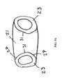
- Figure 2Btaken along the lines 2B---2B of Figure 2 , shows that, at the locations of the ports 20, hollow tubes 22 are separated from one another to form the walls defining the periphery of ports 20. It is advisable to have a radius (i.e., rounded edges 26) leading into the port so to reduce the stress concentration and to facilitate the molding process.
- a radiusi.e., rounded edges 26
- Figure 2Cis an isometric view of bow limb 12 showing one port in which hollow tubes 22 and internal wall 24 can be clearly seen. Also shown is port 20 formed by curved wall 30 which may have the shape of a portion of a cylinder. Curved wall 30 is formed from the facing walls of hollow tubes 22, where the facing walls have been kept separated to prevent them from fusing together during the molding process.
- Figure 3is a longitudinal section view along the bow limb that shows at locations other than the ports, hollow tubes 22 are positioned side-by-side and are fused together along much of their lengths to form common wall 24 that extends along the centerline of the bow limb, preferably bisecting the bow limb interior.
- facing surfaces 30a and 30b of tubes 22are separated during molding to form ports 20 in the shape of double opposing arches which act as geometric supports to allow deformation and return.
- internal wall 24provides structural reinforcement to resist cross section reduction and catastrophic buckling failures.
- Figure 4shows an alternative embodiment of the bow limb, in which bow limb 12 is designed using a multiple tube construction with allows for ports 20 and ports 20' to be positioned along 2 different rows. In this case, three tubes have been used.
- Figure 4Ashows a cross sectional view of bow limb 12 taken along the lines 4A---4A in Figure 4 .
- 3 tubes 42, 43 and 44are used to create the bow limb which creates two internal walls 46 and 48 therebetween.
- FIG 4Btaken along the lines 4B---4B of Figure 4 , shows that ports 20 are firmed when tubes 43 and 44 are separated from one another to form the walls defining such ports.
- tubes 42 and 43are separated from one another to form walls defining such ports.
- ports 20 and 20'be collocated or aligned along the length of bow limb 12. They may be offset from each other, in which case, the separations of tubes 42 and 43 and tubes 43 and 44 would be at different locations.
- Figure 5shows a side view of the bow riser 14 with ports 21 formed therein.
- Ports 21have axes which may be perpendicular to the direction of travel of the arrow or which may be oriented at different angular offsets from the perpendicular.
- the stiffness of the risercan be controlled with the size, location, shape, and number of ports.
- the portscan deform to absorb vibrations. Because no fibers are severed, the bow riser structure retains its stiffness and strength.
- the bow risermay also be lighter in weight as a result of the formation of the ports.
- Figure 5Ais cross sectional view of the bow riser taken along lines 5A---5A of Figure 5 .
- the hollow tubes 23are separated from one another to form walls 31 defining the peripheral walls of port 21. Again it is advisable to have radiused edges 27 leading into port 21 so to reduce the stress concentration and to facilitate the molding process.
- Figure 6shows a rear view of an alternative embodiment of the bow riser wherein the axes of ports 25 are aligned with the direction of travel of the arrow.
- port 27may be formed to serve as an arrow rest, which allows the arrow to pass through the center of the bow riser. This allows for a secure location to rest the arrow while retaining improved stiffness and strength in this area.
- Figure 6Ashows a cross sectional view of the bow riser 14 taken along the lines 6A---6A of Figure 6 .
- hollow tubes 23are separated from one another to form the peripheral wall 31 defining ports 21.
- Bow risers formed with ports oriented in this mannerwill have a greater stiffness fore to aft, and be more flexible side to side.
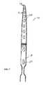
- Figure 7is a rear view of a one piece bow constructed in accordance with an alternative embodiment of the present invention.
- two tubesare used continuously from tip 16 of bow limb 12 through riser 14 to the other tip end 16a of bow limb 12a (not shown) to create a one piece bow system.
- Ports 20are located along the bow limb 12 as well as the riser 14.
- a particular port 27is positioned in the bow riser 14 to serve as an arrow rest.
- a conventional arrow restmay also be used.
- Figure 8shows an alternative embodiment of bow riser 14 in which utilizes a multiple tube construction which allows for ports 20 and 20a to be oriented at different angles.
- ports 20have axes oriented perpendicular to the direction of travel of the arrow, and ports 20a have axes which are parallel to the direction of travel of the arrow, although any angles may theoretically be used.
- a bow riser with this type of designwould be considered to have the benefits of the ports in two directions.
- This particular exampleshows ports 20 and 20a alternating. It is also possible arrange the ports in any desirable sequence, orientation and location.
- a conventional arrow rest 29is used. It is also possible to form a port to serve as an arrow rest, shown as reference number 29 in Figure 8 .
- FIG. 8B cross sectionis in the region of port 20a which has an axis which is parallel to the direction of travel of the arrow.
- hollow tubes 42 and 43have remained fused together, and hollow tubes 44 and 45 have remained fused together, however, tubes 42 and 43 are separated from the tubes 45 and 44 respectively during the molding process to create the port 20a.
- FIG 8Cis an isometric view of a cutaway portion of the bow riser 14 of Figure 8 showing ports 20 with axes oriented perpendicular to the direction of travel of the arrow, and ports 20a with axes oriented parallel to the direction of travel of the arrow.
- portsmay be formed by separating two tubes from the other two tubes.
- hollow tubes 42 and 45have remained together as well as hollow tubes 43 and 44.
- hollow tubes 42 and 43have remained together as well as hollow tubes 44 and 45.
- Molding the parts using multiple tubesallows greater design options. For example, separating the hollow tubes at selected axial locations along the bow in order to mold large oval shaped openings between the tubes, allows the characteristics of the bow to be varied as desired.
- Figure 9is an isometric cutaway view of a four tube structure 52 with ports for all tubes located in the same location.
- hollow tubes 47, 48, 49, and 50are all separated in the same location to form four ports 51 there between.
- Figure 9Ais a cross sectional view of tube structure 52 in Figure 9 taken along the lines 9A-9A.
- a port 51 having four openings 51 a-dis formed. This particular embodiment would provide more flexibility and resiliency in both the perpendicular and parallel directions with respect to the direction of travel of the arrow.
- a multiple tube designthere can be any number of ports and orientations of ports depending on the number of hollow tubes used and how many are separated to form these ports.
- the inventionis not meant to be limited to designs using only two or four tubes.
- the axis of the portwould not necessarily have to pass through the center of the bow riser, but would instead be offset to one side as shown in Figure 4 .
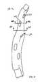
- Figure 10shows an example of a multiple tube design for a riser having three hollow tubes 200a, 200b and 200c, and irregularly-shaped ports 205 and port orientations.
- tubes 200a-care not restricted to being disposed in a single plane or with their longitudinal axes oriented parallel to each other.
- the tubeslie in varying planes and contact the other tubes at various points along their surfaces, defining irregular ports 205 between the tubes and short, irregularly-shaped internal walls at the attachment points of the tubes.
- attachment members 210which may be used to attach bow limbs (not shown) to the riser portion of the bow.
- the attachment membersmay be composed of a composite material, or some other material, such as metal or ceramic, and may be either co-molded with the riser or attached later via a mechanical means, such as a with a screw or an adhesive.
- the pre-formed partis placed into the mold with the uncured tubes and becomes attached as the composite material of which the tubes are composed cures.
- the attachment membersare to be composed of a composite material, they may be cured at the same time as the riser, making the riser and the attachment members appear as a single structure.
- insert members 212 and 214which are disposed in ports.
- insert member 212is an attachment device for various accessories that may be used with the bow
- insert 214is a weight to provide damping and to reduce vibrational movement of the bow.
- the insertsmay serve any function, for example, elastomeric inserts may be provided in various ports to provide vibrational damping.
- a riser having tubes arranged in this manneroffers several advantages.
- the tubescan be arranged so that the centroid of all tubes is located in a desired location to control the bending of the riser when the bow is flexed. This results in a more accurate shot.
- Another advantage of this arrangement of the tubesis to vary the stiffness of the riser in all directions by varying the tube diameters, positions, and contact locations with other tubes.
- the tubesalso look like branches of trees and bushes, to give the bow an improved camouflage look.
- Figures 12A-Dillustrate some examples of the variety of shapes possible for the ports. Depending on the performance required of the structure at a particular location, more decorative port shapes can also be used. The invention is not meant to be limited to only those ports shown, but can utilize ports of any shape.
- the quantity, size, and spacing of the portscan vary according to the performance desired.
- the internal wallassists in resisting the buckling of the tubular construction from the extreme bending of the bow limbs, especially ion the three tube design, which creates two internal walls.
- the preferred embodiments of the present inventionuse multiple continuous composite tubes which are separated to form apertures in the form of double opposing arches at various locations in the bow.
- Tubular structurescan also be too rigid due to their geometry, and therefore difficult to draw the arrow to the maximum position. Adding ports along the length of the bow limb increases flexibility in key areas for enhanced performance.
- the ported tubular structurealso is more stable.
- the ported bow limbacts like parallel limbs with bracing in between to increase the torsional stiffness and stability.
- the ported bow limballows for air to pass through the ports which allows the bow limbs to return with more velocity and therefore greater arrow velocity.
- the inventionallows the bow to be custom tuned during the manufacturing process in terms of its stiffness and resiliency by varying, in addition to the material used and the geometry of the bow itself, the size, number, orientation and spacing of the ports in the bow.
- the bowis preferably constructed of sheet of unidirectional reinforcement fibers, such as carbon fibers, embedded in an uncured resin such as epoxy.
- the resincures when heat is applied.
- This materialis often referred to as "prepreg".
- the prepreg tubes used to make the bow, or its various parts,may be formed by rolling sheets of prepreg into a tube. Alternately, the prepreg tubes may be formed of reinforcement fibers and a thermoplastic material, using a technique similar to that disclosed in U.S. patent No. 5,176,868 .
- the fiber reinforcement materialsmay be composed of, for example, carbon, fiberglass, aramid or boron, or any other such material known in the art.
- the resinmay be, for example, epoxy, polyester, vinyl ester, nylon, polyamide resins, ABS and PBT, or any other material known in the art for this purpose.
- each tubeWhen molding the same bow limb using two prepreg tubes, each tube should be approximately half the size of the cross section of the bow limb, with three, each should be about one third of the size of a cross section of the bow, etc.
- a polymer bladderis inserted into the middle of each prepreg tube and is used to generate internal pressure to consolidate the plies upon the application of heat.
- the mold packing processconsists of taking each prepreg tube and internal bladder and positioning them into a mold cavity. An air fitting is then attached to the bladder. The process is repeated for each tube depending on how many are used. Care should be taken for the position of each tube so that the internal wall formed between the tubes is oriented properly, and that pins can be inserted between the tubes to separate the tubes in selected locations to form the ports during pressurization. The pins are secured into portions of the mold and are easily removed.
- the moldis designed with a cavity that will form the external shape of the molded part.
- the moldis pressed closed in a heated platen press and air pressure for each tube is applied simultaneously to retain the size and position of each tube and the wall which is formed therebetween. Simultaneously, the tubes will form around the pins to form the ports.
- the viscosity of the epoxy resindecreases and the tubes expand, pressing against each other until expansion is complete and the epoxy resin is cross linked and cured.
- the moldis then opened, the pins and bladders removed, and the part is removed from the mold.
- multiple tubesmay be formed of a single, long tube which has been reversed upon itself.
- the additional tubescould also be a separate tube construction using internal air pressure for consolidation or have an expanding internal foam core to provide such pressure.
- the orientation of the wall in the bow risercan be positioned to take advantage of the anisotropy it offers. If more bending flexibility is desired, the wall can be positioned along the neutral axis of bending. If greater stiffness is needed, then the wall can be positioned like an "I Beam" at 90 degrees to the neutral axis to greatly improve the bending stiffness.
- a ported double tube structurehas a combination of exterior walls, which are continuous and form the majority of the structure, and ported walls, which are oriented at an angle to the exterior walls, which provide strut like reinforcement to the tubular structure.
- the cylindrical walls of the portsprevent the cross section of the tube from collapsing, which significantly improves the strength of the structure.
- the stiffness and resiliency of the ported double tube structurecan be adjusted to be greater or less than a standard single hollow tube. This is because of the option of orienting the internal wall between the tubes as well as the size, shape, angle and location of the ports.
- the portscan be stiff if desired, or resilient allowing more deflection and recovery, or can be designed using different materials or a lay-up of different fiber angles to produce the desired performance characteristics of the structure.
- the structurecan be further refined by using more than two tubes in a configuration where a facing side of each of the three tubes is fused to a facing side of the other two tubes, forming a "Y" shaped internal reinforcing wall.
- This type of three tube designalso allows for apertures to occur in 120 degree offsets, providing specific stiffness tailoring along those directions.
- using four tubesprovides the possibility of having apertures at ninety degree angles to each other and alternately located along the length of the tubular part to achieve unique performance and aesthetic levels. Another option is to locate the multiple ports in the same location to achieve more of an open truss design.
- the bowmay be formed from one or more pre-formed portions which are fused with a portion having a multiple tube design.
- the riser portionmay be pre-molded or pre-formed. The riser could then be co-molded with the limb portions or, alternatively, have the limb portions attached after molding using a conventional method of attachment.
- the single composite tubecan be a portion of the bow and co-molded with the multiple tubes to produce a lighter weight alternative to a 100 % multiple tube construction.
- the single tubecould also be composed of a composite material, or may be composed of an alternative material, such as metal, wood or plastic.
- the composite single tubecan be a portion of the bow riser and fused or co-molded with the multiple prepreg tubes which form the bow limbs. This can produce a lighter weight structure that can still achieve the performance and aesthetic requirements of the product.
- the forward ends 62 of a pair of prepreg tubes 60a, 60b, each having an inflatable bladder 64,are inserted into one end 65 of a composite single tube 66.
- the structureis then placed inside a mold, which should be shaped, on either side of the juncture 70 of the prepreg tubes 60a, 60b and the composite single tube 66, such that the outside surface of the unit is continuous.
- a pin or mold member(not shown) can be placed between the prepreg tubes 60a, 60b where a port 20 is to be formed.
- the moldis then closed and heated, as the bladders 64 are inflated, so that the prepreg tubes assume the shape of the mold, the mold member keeping the facing walls 71a, 71b apart so as to form the port 20. As shown, the tubes 60a, 60b will form a common wall at seam 72.
- frame member 74is removed from the mold, and the mold member or pin is removed, leaving port 20.
- seam 70 between the composite portions 60a, 60b of frame member 74 and composite single tube portion 66should be flush.
- the tube portion 66may also be made of metal to produce a less expensive product than using 100% composite materials.
- a double opposing arch structureusing 100% metal materials.
- the preferred method to produce this structureis to start with a metal tube with a "D" shaped cross section.
- the tubecan then be formed with a half arch bend along a portion of its length.
- a similar operationcan be done with another metal tube.
- the two tube halvescan then be attached by fixing the flat sides of the D shaped cross section so that the two half arches oppose each other.
- the tubescan be welded or bonded together resulting in a structure with an internal reinforcing wall and a double opposing arch shaped aperture.
- An alternative method to produce a multiple tube structure out of metalis to start with a metal tube such as aluminum, titanium, steel, or magnesium for example, and deform the tube in local areas to create dimples or craters in the surface of the tube on opposing sides. The centers of these dimples can be removed leaving a circular aperture through the tube. A tubular section can then be positioned through these circular apertures and fixed to the edges of this dimple area of the primary tube using a welding process to create the 3D structure. The result will be a structure with the primary tube being a single hollow tube with other single hollow tubes attached in a transverse manner internal to the primary tube.
- a metal tubesuch as aluminum, titanium, steel, or magnesium for example
- the portscan vary by shape, size, location, orientation and quantity.
- the portscan be used to enhance stiffness, resilience, strength, control, aerodynamics and aesthetics. For example in a low stress region, the size of the port can be very large to maximize its effect and appearance. If more deflection or resilience is desired, the shape of the aperture can be very long and narrow to allow more flexibility.
- the portsmay also use designer shapes to give the product a stronger appeal.
- the portscan be oriented and shaped at a particular angle, and constructed using fibers such as aramid or liquid crystal polymer. As the port deforms as a result of bending deflection, its return to shape can be controlled with various viscoelastic materials which will increase vibration damping. Another way to increase vibration damping is to insert an elastomeric material inside the port.
- FIG. 15illustrates a bow riser 14 with a port 80 located on a recessed surface 82.
- the bow limb 12has a corresponding port 80' which lines up with port 80 when the bow limb end 84 is placed on the recessed area 82.
- a fastening meansconnects the bow limb 12 to the riser 14 through the ports 80 and 80'.
- the multiple tube designcan also facilitate the attachment of the bow limbs to the riser, the attachment of accessories or the attachment of a wheel and pulley system for a compound bow.
- Figure 16shows an alternative design where the riser 14 has a slot 88 formed into the end of the structure. The upper and lower legs which form the slot 88 have a pair of aligned ports, one of which 80 is shown in Figure 16 .
- Bow limb 12has an end 86 with a reduced thickness to fit into the slot 88 of bow riser 14.
- a fastening meanssuch as a pin, connects bow limb 12 to bow riser 14 through the ports 80 and 80'.
- the bow limbsmay also be attached to the riser using an adhesive, or a combination of a pin and an adhesive.
- the ports used for attachment purposesmay be constructed in the same manner as discussed previously for structural and performance-enhancing ports.
- Figure 17illustrates generally a process which may be used to make the bow limb and riser.
- a pair of prepreg tubes 100, 102extends side-by-side from the butt end 29 towards the tip end 16.
- the inside, common wall 104 of the tubes 100, 102is cut out, the outside walls of the prepreg tubes 100, 102 are folded over one another, so as to close off the forward end and create a space 106 between the outside walls 108 and the forward end 105 of the common wall 104.
- An inflatable bladder 110extends through the interior of one prepreg tube 100, through the space 106 at the forward tip 16, and back through the other prepreg tube 102, so that opposite ends 112, 112a of the bladder 110 extend out of the open butt end 29 of the tubes.
- a mold pin 114is inserted between the facing walls 104 of the tubes 110, 112 to form a port. This structure is then placed in a mold which is heated, while the bladder 110 is inflated, to form the bow limb. After molding a cap may be secured by any suitable means to close off the butt end 29 of the bow.
- the bowcan be molded with the butt end 29 closed and the tip end 16 open (i.e., the opposite of Figure 17 ), in which case the bow tip is secured after molding.
- the bow limbcan be molded with both ends open, using a pair of inflatable bladders.
- the tip and/or buttmay, if desired, be closed off after molding by securing a tip and/or butt piece, respectively, to the bow limb. In such a case, the ends of the tubes would not be folded over one another.
Landscapes
- Engineering & Computer Science (AREA)
- General Engineering & Computer Science (AREA)
- Toys (AREA)
- Rigid Pipes And Flexible Pipes (AREA)
- Laminated Bodies (AREA)
- Golf Clubs (AREA)
Abstract
Description
- The present invention relates to an archery bow, and, more particularly, to an archery bow composed of a composite material having ports defined in portions thereof.
- The traditional bow, also called a long bow, is typically a solid or laminated wood structure having a variable cross section which is larger in the handle region and which transitions to a generally flat cross section in the limb area, away from the central region. A more contemporary bow, called a recurve bow, is shaped such that the tips of the limbs of the bow curve away from the archer. This allows for improved spring back and higher arrow velocities. A still more contemporary bow, called a compound bow, has a wheel and pulley mechanism, which further enhances arrow velocity.
- The bow originated as a single piece structure made of a single piece of wood. The bow structure was later designed with laminated wood to take advantage of combining different species of wood as well as using strengthening adhesives to bond the plies together. While the laminated structure can resist repeated flexing and is very durable, some disadvantages exist. A laminated structure is limited to a flat geometry, which is an inefficient design when the bow limb is traveling through the air. When the bow is fully loaded and the bow limbs are undergoing maximum deflection, the faster they are able to return, the higher arrow velocity. In addition, the flat panel shaped of a laminated structure has very poor torsional properties. This can decrease the accuracy of the bow system.
- Further improvements were made by adding fiber reinforced composites to the wood laminated bow structure. Fibers such as fiberglass, aramid, and carbon fiber have been used in a variety of polymer matrices.
- The bow was further advanced by separating the central region (the riser) from the two outer regions (the limbs). The combination of a rigid riser with flexible limbs created a more powerful and accurate bow.
- The performance of an archery bow, measured in terms of accuracy, arrow velocity, and numerous other factors, can be affected by a number of characteristics of the bow, such as weight, bending flex, resiliency, vibration damping, and strength.
- Arrow velocity is heavily dependent upon the resiliency of a bow, which is a measure of the ability of the bow to recover from a flexed state when the arrow is drawn back. The stiffness of the bow limbs is also important. The stiffness and stiffness distribution along the length of the limb can affect the pull back force required as well as the velocity of the shot.
- The accuracy of a bow is another important characteristic. Accuracy is determined by numerous factors. The limbs of the bow must deflect and return on a consistent basis, and the central portion of the bow, the riser, must be sufficiently rigid to not deflect or twist during aiming or shooting. Vibration damping is another critical performance factor. As the arrow is released, vibrations can be generated which can affect the trajectory of the arrow as it exits the bow.
- The weight of the bow limbs and the riser is also important. A lighter bow limb can return faster, resulting in a faster shot. A light weight riser provides for an overall lighter bow weight or allows for more weight to be added to the bow system to improve the stability and balance of the bow.
- Lastly, the sound the bow makes while shooting is also important when the bow is use for hunting. A more silent bow reduces the chance that the prey will hear the shot and become startled and run away.
- Numerous improvements in bow technology and construction have been patented. An example of a laminated structure is shown in
U.S. Patent No. 2,945,488 (Cravotta, et. al). Examples of changing the cross section of the bow limbs to enhance performance are shown inU.S. Patents Nos. 4,122,821 (Mamo ),6,105,564 (Suppan ) and6,718,962 (Adcock ). Examples of modifying the bow limb by adding grooves and slots for the string are shown inU.S. Patents Nos. 2,836,165 (Bear ),2,957,470 (Barna ) and5,609,146 (Izuta ). An example of a bow with tubular limbs in shown inU.S. Patent No. 4,338,909 (Plummer ). - There are also numerous examples of bow limbs having holes, primarily for the purpose of weight reduction of the limbs. Examples are
U.S. Patents Nos. 4,201,183 (Bodkin ),5,150,699 (Boissevain ),5,503,135 (Bunk ),6,698,413 (Ecklund ) and6,067,974 (Islas ). In each of these examples, the holes are formed by removing material from the bow structure post fabrication, which weakens the structure and causes instability. - U.S. Published Patent Application
US2004/0084039 A1 discloses a bow with a pair of limbs discloses a bow with a pair of limbs spaced a distance apart either side of the riser. Each bow limb is comprised of a braided fiber reinforced polymer. Apertures are formed at each end of the limb as a means of attaching the limbs to the riser and the wheel mechanism. There is no connection between the limbs which will result in an unstable performance because each limb can operate independently. U. S. Patents Nos. 4,644,929 (Peck ) and6,964,271 (Andrews ) also describe bow limbs formed of a pair of parallel limb elements.- There also exist numerous examples of improvements to the handle riser of the bow system to reduce the weight. These include holes and openings which are formed in the riser to reduce the weight, and constructing the riser from lightweight metals such as aluminum and magnesium.
U.S. Pat. No. 5,335,645 (Simonds, et. al ) describes an aluminum riser with recesses machined in the structure to reduce the weight. Examples in the market are the Martin Pro Series or Gold Series of compound bows, or the Samick Masters Series of recurve bows. Other examples are shown inU.S. Patents Nos. 6,257,220 (McPherson, et. al) and 7,066,165 (Perry). - Examples of bow limbs fabricated of fiber reinforced composites are shown in
U.S. Patents Nos. 5,392,756 and5,501,208 (Simmonds ) and5,657,739 (Smith ). Composite materials have also been used to make the bow riser lighter or for improved vibration damping. Examples includeU.S. Patents Nos. 4,693,230 (Sugouchi ),5,269,284 (Pujos, et. al ),5,845,388 and6,669,802 (Andrews, et. al ), and U.S. Published Patent Application No.US2005/0229912 A1 (Piopel, et. al ). - There exists a continuing need for an improved bow that has the combined features of light weight, improved bending stiffness, improved strength, improved aerodynamics and improved vibration damping. In this regard, the present invention substantially fulfills this need.
- The bow system according to the present invention substantially departs from the conventional concepts and designs of the prior art and in doing so provides an apparatus primarily developed for the purpose of maintaining light weight while providing tailored stiffness, greater strength, improved aerodynamics, improved vibration damping, as well as improved appearance.
- The present invention relates to a composite structure for a bow system, including both the limbs and riser, where at lest portions of the structure are comprised of multiple continuous tubes, fused together along their facing surfaces to provide one or more internal reinforcing walls, which provides strength and stiffness advantages. In addition, the tubes can be separated at various locations to form apertures or ports between the tubes. The ports are preferably oval or circular in shape, such as to form opposing arches, which provide additional stiffness, strength, aerodynamic and vibration damping benefits.
- Another advantage of the invention is vibration damping. Vibrations are damped more effectively with the opposing arch construction. This is because the movement and displacement of the arches absorbs energy which damps vibrations. As the tubular parts deflect, the shape of the ports can change, allowing a relative movement between the portions of the tube either side of the port. This movement absorbs energy which damps vibrations. A quieter bow structure is said to be more accurate.
- The ports also provide an aerodynamic advantage by allowing air to pass through the bow. The bow limbs accelerate at a rapid rate when the arrow is released from a full draw. The improved maneuverability of the bow limb will improve arrow velocity.
- Finally, there is a very distinguished appearance to a bow made according to the invention. The ports are very visible, and give the tubular part a very light weight look, which is important in bow marketing. The ports can also be painted a different color, to further enhance the signature look of the technology.
- There has thus been outlined, rather broadly, the more important features of the invention such that the detailed description thereof that follows may be better understood and in order that the present contribution to the art may be better appreciated. There are, of course, additional features of the invention that will be described hereinafter and which will form the subject matter of the claims attached.
- The improved bow of the present invention provides a new and improved bow system of durable and reliable construction, which may be easily and efficiently manufactured at low cost with regard to both materials and labor
- In addition, the improved bow has improved strength and fatigue resistance, improved vibration damping characteristics, and can provide specific stiffness zones at various locations along the length of the bow.
- The apertures or "ports" defined in the bow can improve the aerodynamics of the bow limb, as well as provides a bow having a unique look and improved aesthetics.
Figure 1 is a side view of a first embodiment of a bow constructed in accordance with the present invention.Figure 2 is a rear view of a first embodiment of a bow limb constructed in accordance with the present invention.Figure 2A is a cross sectional view of the bow limb taken alonglines 2A---2A ofFigure 2 .Figure 2B is a cross sectional view of the bow limb taken alonglines 2B---2B ofFigure 2 .Figure 2C is an isometric view of a portion of the bow limb shown inFigure 2 .Figure 3 is a longitudinal sectional view of a portion of the bow limb shown inFigure 2 .Figure 4 shows an alternative embodiment of a bow limb constructed in accordance with the present invention.Figure 4A is a cross sectional view along thelines 4A---4A ofFigure 4 .Figure 4B is a cross sectional view along the lines 4B---4B ofFigure 4 .Figure 5 is a side view of an embodiment of a bow riser constructed in accordance with the present invention.Figure 5A is cross sectional view of the bow riser taken along lines 5A --- 5A ofFigure 5 .Figure 6 is a rear view of an embodiment of a bow riser constructed in accordance with the present invention.Figure 6A is cross sectional view of the bow riser taken alonglines 6A---6A ofFigure 6 .Figure 7 is a rear view of an alternative embodiment of the invention in which the bow is constructed as a one-piece structure in accordance with the present invention.Figure 8 is an isometric view of a bow riser constructed with a multiple tube design.Figure 8A is a cross section of the bow riser inFigure 8 taken along lines 8A---8A.Figure 8B is a cross section of the bow riser inFigure 8 taken along lines 8B---8B.Figure 8C is an isometric cutaway view of a portion of the bow riser shown inFigure 8 .Figure 9 is an isometric cutaway view of an alternate embodiment of a bow riser made with a multiple tube construction having multiple, co-located ports.Figure 9A is a cross sectional view along thelines 9A---9A ofFigure 9 .Figures 10 and11 show various views of an embodiment of a bow riser constructed in accordance with the invention, in which three tubes are used which are fused together at various points along their lengths to create a riser with irregularly-shaped ports.Figures 12A-D show various possible shapes of ports.Figures 13 and 14 are perspective views illustrating a process for forming a frame member having a multiple tube construction to a member having a single tube construction.Figure 15 shows a means of attaching a bow limb and riser of the present invention.Figure 16 shows an alternative means of attaching a bow limb and riser of the present invention.Figure 17 is a longitudinal sectional view of an example of a bow structure prior to molding.- As described below, the bow system is formed of two or more tubes which are fused together along facing surfaces to form internal, common wall(s). The internal, common walls improve the strength of the bow by acting as a brace to resist compression of the cross section resulting from bending loads.
- To form the ports, the facing surfaces of the tubes are kept apart at selected locations during molding, thereby forming openings. On either side of the openings, the tubes are joined together to form the internal wall. These ports are formed without drilling any holes, which provides a strength advantage because no reinforcement fibers in the composite are severed to form the holes.
- The resulting structure is found to have superior performance characteristics for several reasons, and can provide performance benefits for both the bow limbs and the bow riser.
- For bow limbs, the ports are preferably in the shape of double opposing arches. This allows the structure to deflect, deforming the ports, and return with more resiliency. The ports also allow greater bending flexibility than would traditionally be achieved in a tubular design. The internal wall between the hollow tubes adds strength to resist compressive buckling loads generated from the extreme bending of the bow limbs. The ports allow air to pass through, making the bow limbs more aerodynamic to improve the return velocity of the bow limb when the arrow is released. Finally, the structure can also improve accuracy by providing stability of the bow limb and damping vibrations due to the deformation of the ports.
- The performance of the bow riser is improved by the internal wall between the tubes which, adds rigidity and strength. In addition, the ports formed between the tubes can have multiple orientations to achieve different performance benefits. Vibration damping is also improved because the ports can deform, which absorbs energy and damps vibration. This improves the accuracy of the bow system.
Figure 1 illustrates a bow, which is referred to generally by thereference numeral 10. Thebow 10 includeslimb portions 12 and 12a that connect to theriser 14. Thelimb portions 12 and 12a have tip portions 16 and 16a to whichstring 18 is connected.Bow limbs 12 and 12a may haveports bow riser 14 may haveports 21 molded into the structure.Figure 2 shows a front view ofbow limb 12 showing a preferred embodiment of the invention in whichports 20 extend throughbow limb 12, oriented in line and with axes parallel to the direction of travel of the bow limb. Theports 20 may be located along the length of thebow limb 12. Limb 12a would typically be identical tolimb 12, but may have a different configuration.Figure 2A , taken along thelines 2A---2A ofFigure 2 , shows the twohollow tubes 22 which form the structure of the shaft in this embodiment. Thehollow tubes 22 are joined together to form aninternal wall 24. The preferred location of theinternal wall 24 is near the central axis of the bow limb. Both of thehollow tubes 22 are preferably about the same size and, when molded together, form a bow limb having a flattened "D" shape cross section.Figure 2B , taken along thelines 2B---2B ofFigure 2 , shows that, at the locations of theports 20,hollow tubes 22 are separated from one another to form the walls defining the periphery ofports 20. It is advisable to have a radius (i.e., rounded edges 26) leading into the port so to reduce the stress concentration and to facilitate the molding process.Figure 2C is an isometric view ofbow limb 12 showing one port in which hollowtubes 22 andinternal wall 24 can be clearly seen. Also shown isport 20 formed bycurved wall 30 which may have the shape of a portion of a cylinder.Curved wall 30 is formed from the facing walls ofhollow tubes 22, where the facing walls have been kept separated to prevent them from fusing together during the molding process.Figure 3 is a longitudinal section view along the bow limb that shows at locations other than the ports,hollow tubes 22 are positioned side-by-side and are fused together along much of their lengths to formcommon wall 24 that extends along the centerline of the bow limb, preferably bisecting the bow limb interior. At selected locations whereports 20 are to be formed, facingsurfaces tubes 22 are separated during molding to formports 20 in the shape of double opposing arches which act as geometric supports to allow deformation and return. In addition,internal wall 24 provides structural reinforcement to resist cross section reduction and catastrophic buckling failures.Figure 4 shows an alternative embodiment of the bow limb, in which bowlimb 12 is designed using a multiple tube construction with allows forports 20 and ports 20' to be positioned along 2 different rows. In this case, three tubes have been used.- To form ports in multiple rows, multiple tubes are needed.
Figure 4A shows a cross sectional view ofbow limb 12 taken along thelines 4A---4A inFigure 4 . In this example, 3tubes internal walls Figure 4B , taken along the lines 4B---4B ofFigure 4 , shows thatports 20 are firmed whentubes tubes edge 26 and 26' leading into the port so to reduce the stress concentration and to facilitate the molding process. Note that it is not a requirement thatports 20 and 20' be collocated or aligned along the length ofbow limb 12. They may be offset from each other, in which case, the separations oftubes tubes Figure 5 shows a side view of thebow riser 14 withports 21 formed therein.Ports 21 have axes which may be perpendicular to the direction of travel of the arrow or which may be oriented at different angular offsets from the perpendicular. As the bow is drawn to full displacement, the stiffness of the riser can be controlled with the size, location, shape, and number of ports. As the arrow is released, the ports can deform to absorb vibrations. Because no fibers are severed, the bow riser structure retains its stiffness and strength. The bow riser may also be lighter in weight as a result of the formation of the ports.Figure 5A is cross sectional view of the bow riser taken along lines 5A---5A ofFigure 5 . Here it can be seen thehollow tubes 23 are separated from one another to formwalls 31 defining the peripheral walls ofport 21. Again it is advisable to have radiusededges 27 leading intoport 21 so to reduce the stress concentration and to facilitate the molding process.Figure 6 shows a rear view of an alternative embodiment of the bow riser wherein the axes ofports 25 are aligned with the direction of travel of the arrow. In addition,port 27 may be formed to serve as an arrow rest, which allows the arrow to pass through the center of the bow riser. This allows for a secure location to rest the arrow while retaining improved stiffness and strength in this area.Figure 6A shows a cross sectional view of thebow riser 14 taken along thelines 6A---6A ofFigure 6 . Here it can be seen thathollow tubes 23 are separated from one another to form theperipheral wall 31 definingports 21. Again it is advisable to have a radiused edge leading intoport 21 to reduce the stress concentration and to facilitate the molding process. Bow risers formed with ports oriented in this manner will have a greater stiffness fore to aft, and be more flexible side to side.Figure 7 is a rear view of a one piece bow constructed in accordance with an alternative embodiment of the present invention. In this example, two tubes are used continuously from tip 16 ofbow limb 12 throughriser 14 to the other tip end 16a of bow limb 12a (not shown) to create a one piece bow system.Ports 20 are located along thebow limb 12 as well as theriser 14. Aparticular port 27 is positioned in thebow riser 14 to serve as an arrow rest. A conventional arrow rest may also be used.- Should it be desired in this embodiment to have ports define in the riser having axes perpendicular to the direction of travel of the arrow, it is possible to construct the riser portion from four tubes and the bow limb portion from two tubes, and fuse them together, possibly with an overlapping single tube, to create the one-piece structure, in the manner shown in
Figures 11 and12 . Figure 8 shows an alternative embodiment ofbow riser 14 in which utilizes a multiple tube construction which allows forports ports 20 have axes oriented perpendicular to the direction of travel of the arrow, andports 20a have axes which are parallel to the direction of travel of the arrow, although any angles may theoretically be used. A bow riser with this type of design would be considered to have the benefits of the ports in two directions. This particular example showsports conventional arrow rest 29 is used. It is also possible to form a port to serve as an arrow rest, shown asreference number 29 inFigure 8 .- In order to form ports in multiple directions, multiple tubes are needed. In the example of
Figure 8A ,4 tubes internal wall 46 in the form of an "X". - The
Figure 8B cross section is in the region ofport 20a which has an axis which is parallel to the direction of travel of the arrow. In this example,hollow tubes hollow tubes tubes tubes port 20a. Figure 8C is an isometric view of a cutaway portion of thebow riser 14 ofFigure 8 showingports 20 with axes oriented perpendicular to the direction of travel of the arrow, andports 20a with axes oriented parallel to the direction of travel of the arrow. As described above in connection withFigures 8A and 8B , ports may be formed by separating two tubes from the other two tubes. In this example, to formport 20,hollow tubes hollow tubes port 20a,hollow tubes hollow tubes - Molding the parts using multiple tubes allows greater design options. For example, separating the hollow tubes at selected axial locations along the bow in order to mold large oval shaped openings between the tubes, allows the characteristics of the bow to be varied as desired.
Figure 9 is an isometric cutaway view of a fourtube structure 52 with ports for all tubes located in the same location. In this example,hollow tubes ports 51 there between.Figure 9A is a cross sectional view oftube structure 52 inFigure 9 taken along thelines 9A-9A. Here it can be seen that because all hollow tubes are separated at the same location, aport 51 having fouropenings 51 a-d is formed. This particular embodiment would provide more flexibility and resiliency in both the perpendicular and parallel directions with respect to the direction of travel of the arrow.- In a multiple tube design, there can be any number of ports and orientations of ports depending on the number of hollow tubes used and how many are separated to form these ports. The invention is not meant to be limited to designs using only two or four tubes. For example, with a 3 tube design, the axis of the port would not necessarily have to pass through the center of the bow riser, but would instead be offset to one side as shown in
Figure 4 . Figure 10 shows an example of a multiple tube design for a riser having threehollow tubes 200a, 200b and 200c, and irregularly-shapedports 205 and port orientations. In this design, tubes 200a-c are not restricted to being disposed in a single plane or with their longitudinal axes oriented parallel to each other. In this design, the tubes lie in varying planes and contact the other tubes at various points along their surfaces, definingirregular ports 205 between the tubes and short, irregularly-shaped internal walls at the attachment points of the tubes.- Also shown in
Figure 10 areattachment members 210 which may be used to attach bow limbs (not shown) to the riser portion of the bow. In this case, the attachment members may be composed of a composite material, or some other material, such as metal or ceramic, and may be either co-molded with the riser or attached later via a mechanical means, such as a with a screw or an adhesive. In the co-molding process, the pre-formed part is placed into the mold with the uncured tubes and becomes attached as the composite material of which the tubes are composed cures. If the attachment members are to be composed of a composite material, they may be cured at the same time as the riser, making the riser and the attachment members appear as a single structure. - Also shown in
Figures 10 and11 areinsert members insert member 212 is an attachment device for various accessories that may be used with the bow, and insert 214 is a weight to provide damping and to reduce vibrational movement of the bow. The inserts may serve any function, for example, elastomeric inserts may be provided in various ports to provide vibrational damping. - A riser having tubes arranged in this manner offers several advantages. The tubes can be arranged so that the centroid of all tubes is located in a desired location to control the bending of the riser when the bow is flexed. This results in a more accurate shot. Another advantage of this arrangement of the tubes is to vary the stiffness of the riser in all directions by varying the tube diameters, positions, and contact locations with other tubes. The tubes also look like branches of trees and bushes, to give the bow an improved camouflage look.
Figures 12A-D illustrate some examples of the variety of shapes possible for the ports. Depending on the performance required of the structure at a particular location, more decorative port shapes can also be used. The invention is not meant to be limited to only those ports shown, but can utilize ports of any shape.- In all orientations, the quantity, size, and spacing of the ports can vary according to the performance desired. In addition, the internal wall assists in resisting the buckling of the tubular construction from the extreme bending of the bow limbs, especially ion the three tube design, which creates two internal walls.
- The preferred embodiments of the present invention use multiple continuous composite tubes which are separated to form apertures in the form of double opposing arches at various locations in the bow.
- When considering tubular constructions for bow limbs, there exist other challenges. Because of the severe bending of the bow limbs when shooting an arrow, high compression buckling loads exist. A single tubular structure cannot withstand these compressive stresses and will buckle under the stress. However, the internal wall(s) created by the present invention adds sufficient strength to resist these stresses.
- Tubular structures can also be too rigid due to their geometry, and therefore difficult to draw the arrow to the maximum position. Adding ports along the length of the bow limb increases flexibility in key areas for enhanced performance.
- The ported tubular structure also is more stable. The ported bow limb acts like parallel limbs with bracing in between to increase the torsional stiffness and stability.
- Finally, the ported bow limb allows for air to pass through the ports which allows the bow limbs to return with more velocity and therefore greater arrow velocity.
- The invention allows the bow to be custom tuned during the manufacturing process in terms of its stiffness and resiliency by varying, in addition to the material used and the geometry of the bow itself, the size, number, orientation and spacing of the ports in the bow.
- The bow is preferably constructed of sheet of unidirectional reinforcement fibers, such as carbon fibers, embedded in an uncured resin such as epoxy. The resin cures when heat is applied. This material is often referred to as "prepreg". The prepreg tubes used to make the bow, or its various parts, may be formed by rolling sheets of prepreg into a tube. Alternately, the prepreg tubes may be formed of reinforcement fibers and a thermoplastic material, using a technique similar to that disclosed in
U.S. patent No. 5,176,868 . - The fiber reinforcement materials may be composed of, for example, carbon, fiberglass, aramid or boron, or any other such material known in the art. The resin may be, for example, epoxy, polyester, vinyl ester, nylon, polyamide resins, ABS and PBT, or any other material known in the art for this purpose.
- When molding the same bow limb using two prepreg tubes, each tube should be approximately half the size of the cross section of the bow limb, with three, each should be about one third of the size of a cross section of the bow, etc. A polymer bladder is inserted into the middle of each prepreg tube and is used to generate internal pressure to consolidate the plies upon the application of heat. The mold packing process consists of taking each prepreg tube and internal bladder and positioning them into a mold cavity. An air fitting is then attached to the bladder. The process is repeated for each tube depending on how many are used. Care should be taken for the position of each tube so that the internal wall formed between the tubes is oriented properly, and that pins can be inserted between the tubes to separate the tubes in selected locations to form the ports during pressurization. The pins are secured into portions of the mold and are easily removed.
- The mold is designed with a cavity that will form the external shape of the molded part. The mold is pressed closed in a heated platen press and air pressure for each tube is applied simultaneously to retain the size and position of each tube and the wall which is formed therebetween. Simultaneously, the tubes will form around the pins to form the ports. As the temperature rises in the mold, the viscosity of the epoxy resin decreases and the tubes expand, pressing against each other until expansion is complete and the epoxy resin is cross linked and cured. The mold is then opened, the pins and bladders removed, and the part is removed from the mold.
- If multiple tubes are used, they may be formed of a single, long tube which has been reversed upon itself. The additional tubes could also be a separate tube construction using internal air pressure for consolidation or have an expanding internal foam core to provide such pressure.
- The orientation of the wall in the bow riser can be positioned to take advantage of the anisotropy it offers. If more bending flexibility is desired, the wall can be positioned along the neutral axis of bending. If greater stiffness is needed, then the wall can be positioned like an "I Beam" at 90 degrees to the neutral axis to greatly improve the bending stiffness.
- Molding in of apertures, or ports, at selected locations results in a double opposing arch construction, depending upon the actual shape of the port. The ports, which are preferably oval in shape, create two opposing arches which allow the tubular part to deflect, while retaining the cross sectional shape of the tube because of the three dimensional wall structure provided by the port. For example, a ported double tube structure has a combination of exterior walls, which are continuous and form the majority of the structure, and ported walls, which are oriented at an angle to the exterior walls, which provide strut like reinforcement to the tubular structure. The cylindrical walls of the ports prevent the cross section of the tube from collapsing, which significantly improves the strength of the structure.
- The stiffness and resiliency of the ported double tube structure can be adjusted to be greater or less than a standard single hollow tube. This is because of the option of orienting the internal wall between the tubes as well as the size, shape, angle and location of the ports. The ports can be stiff if desired, or resilient allowing more deflection and recovery, or can be designed using different materials or a lay-up of different fiber angles to produce the desired performance characteristics of the structure.
- The structure can be further refined by using more than two tubes in a configuration where a facing side of each of the three tubes is fused to a facing side of the other two tubes, forming a "Y" shaped internal reinforcing wall. This type of three tube design also allows for apertures to occur in 120 degree offsets, providing specific stiffness tailoring along those directions. As shown in
Figure 9 , using four tubes provides the possibility of having apertures at ninety degree angles to each other and alternately located along the length of the tubular part to achieve unique performance and aesthetic levels. Another option is to locate the multiple ports in the same location to achieve more of an open truss design. - In other embodiments, the bow may be formed from one or more pre-formed portions which are fused with a portion having a multiple tube design. For example, the riser portion may be pre-molded or pre-formed. The riser could then be co-molded with the limb portions or, alternatively, have the limb portions attached after molding using a conventional method of attachment.
- Another option is to combine a single tube with a multiple tube composite design. In this example, the single composite tube can be a portion of the bow and co-molded with the multiple tubes to produce a lighter weight alternative to a 100 % multiple tube construction. The single tube could also be composed of a composite material, or may be composed of an alternative material, such as metal, wood or plastic.
- In this example, the composite single tube can be a portion of the bow riser and fused or co-molded with the multiple prepreg tubes which form the bow limbs. This can produce a lighter weight structure that can still achieve the performance and aesthetic requirements of the product.
- Referring to
Figs. 13-14 , to make this construction, the forward ends 62 of a pair ofprepreg tubes 60a, 60b, each having aninflatable bladder 64, are inserted into oneend 65 of a composite single tube 66. The structure is then placed inside a mold, which should be shaped, on either side of the juncture 70 of theprepreg tubes 60a, 60b and the composite single tube 66, such that the outside surface of the unit is continuous. A pin or mold member (not shown) can be placed between theprepreg tubes 60a, 60b where aport 20 is to be formed. The mold is then closed and heated, as thebladders 64 are inflated, so that the prepreg tubes assume the shape of the mold, the mold member keeping the facingwalls 71a, 71b apart so as to form theport 20. As shown, thetubes 60a, 60b will form a common wall at seam 72. After the prepreg tubes have cured,frame member 74 is removed from the mold, and the mold member or pin is removed, leavingport 20. In this embodiment, seam 70 between thecomposite portions 60a, 60b offrame member 74 and composite single tube portion 66 should be flush. - The tube portion 66 may also be made of metal to produce a less expensive product than using 100% composite materials.
- Yet another option is to construct a double opposing arch structure using 100% metal materials. The preferred method to produce this structure is to start with a metal tube with a "D" shaped cross section. The tube can then be formed with a half arch bend along a portion of its length. A similar operation can be done with another metal tube. The two tube halves can then be attached by fixing the flat sides of the D shaped cross section so that the two half arches oppose each other. The tubes can be welded or bonded together resulting in a structure with an internal reinforcing wall and a double opposing arch shaped aperture.
- An alternative method to produce a multiple tube structure out of metal is to start with a metal tube such as aluminum, titanium, steel, or magnesium for example, and deform the tube in local areas to create dimples or craters in the surface of the tube on opposing sides. The centers of these dimples can be removed leaving a circular aperture through the tube. A tubular section can then be positioned through these circular apertures and fixed to the edges of this dimple area of the primary tube using a welding process to create the 3D structure. The result will be a structure with the primary tube being a single hollow tube with other single hollow tubes attached in a transverse manner internal to the primary tube.
- There are unlimited combinations of options when considering a double opposing arch structure. The ports can vary by shape, size, location, orientation and quantity. The ports can be used to enhance stiffness, resilience, strength, control, aerodynamics and aesthetics. For example in a low stress region, the size of the port can be very large to maximize its effect and appearance. If more deflection or resilience is desired, the shape of the aperture can be very long and narrow to allow more flexibility. The ports may also use designer shapes to give the product a stronger appeal.
- If more vibration damping is desired, the ports can be oriented and shaped at a particular angle, and constructed using fibers such as aramid or liquid crystal polymer. As the port deforms as a result of bending deflection, its return to shape can be controlled with various viscoelastic materials which will increase vibration damping. Another way to increase vibration damping is to insert an elastomeric material inside the port.
- Another advantage of the invention could be to facilitate the attachment of the bow limb to the bow riser.
Figure 15 illustrates abow riser 14 with aport 80 located on a recessedsurface 82. Thebow limb 12 has a corresponding port 80' which lines up withport 80 when thebow limb end 84 is placed on the recessedarea 82. A fastening means connects thebow limb 12 to theriser 14 through theports 80 and 80'. - The multiple tube design can also facilitate the attachment of the bow limbs to the riser, the attachment of accessories or the attachment of a wheel and pulley system for a compound bow.
Figure 16 shows an alternative design where theriser 14 has aslot 88 formed into the end of the structure. The upper and lower legs which form theslot 88 have a pair of aligned ports, one of which 80 is shown inFigure 16 .Bow limb 12 has anend 86 with a reduced thickness to fit into theslot 88 ofbow riser 14. Once inserted, a fastening means, such as a pin, connectsbow limb 12 to bowriser 14 through theports 80 and 80'. The bow limbs may also be attached to the riser using an adhesive, or a combination of a pin and an adhesive. The ports used for attachment purposes may be constructed in the same manner as discussed previously for structural and performance-enhancing ports. Figure 17 illustrates generally a process which may be used to make the bow limb and riser. A pair ofprepreg tubes 100, 102 extends side-by-side from thebutt end 29 towards the tip end 16. At the tip end, the inside,common wall 104 of thetubes 100, 102 is cut out, the outside walls of theprepreg tubes 100, 102 are folded over one another, so as to close off the forward end and create aspace 106 between theoutside walls 108 and theforward end 105 of thecommon wall 104.- An
inflatable bladder 110 extends through the interior of oneprepreg tube 100, through thespace 106 at the forward tip 16, and back through the other prepreg tube 102, so that opposite ends 112, 112a of thebladder 110 extend out of theopen butt end 29 of the tubes. Amold pin 114 is inserted between the facingwalls 104 of thetubes 110, 112 to form a port. This structure is then placed in a mold which is heated, while thebladder 110 is inflated, to form the bow limb. After molding a cap may be secured by any suitable means to close off thebutt end 29 of the bow. - Alternately, the bow can be molded with the
butt end 29 closed and the tip end 16 open (i.e., the opposite ofFigure 17 ), in which case the bow tip is secured after molding. Or, the bow limb can be molded with both ends open, using a pair of inflatable bladders. In either such case, the tip and/or butt may, if desired, be closed off after molding by securing a tip and/or butt piece, respectively, to the bow limb. In such a case, the ends of the tubes would not be folded over one another. - With respect to the above description then, it is to be realized that the optimum dimensional relationships for the parts of the invention, to include variations in size, materials, shape, form, function and manner of operation, assembly and use, are intended to be within the scope of the invention, and all equivalent relationships to those illustrated in the drawings and described in the specification are also intended to be encompassed by the present invention. Also, it is to be understood that the phraseology and terminology employed herein are for the purpose of descriptions and should not be regarded as limiting.
- Therefore, the foregoing is considered as illustrative only of the principles of the invention. It is not desired to limit the invention to the exact construction and operation shown and described, and accordingly, all suitable modifications and equivalents may be resorted to, without deviating from the scope of the invention.
Claims (23)
- An archery bow comprising:a. a riser portion; andb. two limbs, attached to opposite ends of said riser portion;
characterized in thatc. at least one of said riser portion or said limbs comprises:i. two or more hollow tubes, each of said tubes having one or more portions of its surface touching one or more portions of the surface of one or more others of said tubes;ii. wherein said portions of said tubes touching others of said tubes are fused together at said touching portions;iii. wherein the portions of said tubes not touching others of said tubes form the external surface of said bow limbs or riser portion of said bow; andiv. wherein said bow limbs or said riser portion defines one or more ports extending therethrough, said ports being formed between said portions of said one or more tubes not touching others of said tubes. - The archery bow of claim 1characterized in that internal reinforcing walls are formed at said portions of said tubes which are fused together.
- The archery bow of claim 1characterized in that said bow limbs are constructed from an even number of tubes and further wherein said one or more ports extending through said bow limbs are aligned along said longitudinal axis of said bow.
- The archery bow of claim 1characterized in that said bow limbs are constructed from an odd number of tubes and further wherein said one or more ports extending through said bow limbs are offset from said longitudinal axis of said bow.
- The archery bow of claim 1characterized in that one or more ports defined in said riser have axes oriented in a first direction and further wherein one or more ports have axes oriented in a second direction orthogonal to said first direction.
- The archery bow of claim 5characterized in that at least one port having an axis oriented in said first direction and at least one port having an axis oriented in said second direction are collocated on said riser portion, forming a port having four openings.
- The archery bow of claim 1characterized in that said bow limbs and said riser portion are composed of a composite material.
- The archery bow of claim 7characterized in that said composite material is a fiber reinforced resin.
- The archery bow of claim 8characterized in that said fibers are selected from a group consisting of carbon, fiberglass, aramid and boron and further wherein said resin is selected from a group consisting of epoxy, polyester, vinyl ester, nylon, polyamide resins, ABS and PBT.
- The archery bow of claim 1characterized in that it further comprises an insert member composed of an elastomeric material, said insert member being disposed in one or more of said ports.
- The archery bow of claim 1characterized in that said bow limbs or said riser comprise a portion constructed from a single tube fused to a portion constructed from two or more tubes, said one or more ports being defined in said portion of said bow limbs or said riser being constructed from two or more tubes.
- The archery bow of claim 1characterized in that said bow limbs and said riser portion are formed from the same two or more tubes, forming a single structure.
- The archery bow of claim 1characterized in that at least a portion of said bow comprises a single metal tube joined to a multi-tube member.
- The archery bow of claim 1characterized in that said riser portion comprises three or more hollow tubes andin that said riser defines one or more irregularly-shaped ports therein.
- The archery bow of claim 14characterized in that the longitudinal axes of each of said three tubes are irregularly-shaped and oriented in a non-parallel relationship with respect to each other.
- The archery bow of claim 15characterized in that it further comprises an attachment member disposed at either end of said riser, for facilitating the attachment of said bow limbs to said riser.
- The archery bow of claim 16characterized in that said attachment members are pre-formed.
- The archery bow of claim 17characterized in that said attachment members are composed of a material selected from a group consisting of a composite material, metal or ceramic.
- The archery bow of claim 18characterized in that said attachment members are co-molded with said riser portion.
- The archery bow of claim 18characterized in that said attachment members are mechanically joined to said riser portion.
- The archery bow of claim 19characterized in that it further comprises one or more inserts disposed within said one or more ports, said one or more inserts being selected from a group consisting of accessory attachment members, weights and vibration damping members.
- An archery bow of claim 1characterized in that it comprises:a. a riser portion, wherein said riser portion comprises:i. three or more hollow tubes, each of said tubes having one or more portions of its surface touching one or more portions of the surface of one or more others of said tubes;ii. wherein said portions of said tubes touching others of said tubes are fused together at said touching portions;iii. wherein the portions of said tubes not touching others of said tubes form the external surface of said riser portion; andiv. wherein said riser portion defines one or more irregularly-shaped ports extending therethrough, said ports being formed between said portions of said one or more tubes not touching others of said tubes;b. an attachment member disposed at either end of said riser; andc. two limbs, attached to opposite ends of said riser portion via said attachment members.
- The archery bow of claim 22 wherein the longitudinal axes of each of said three tubes are irregularly-shaped and oriented in a non-parallel relationship with respect to each other.
Applications Claiming Priority (1)
| Application Number | Priority Date | Filing Date | Title |
|---|---|---|---|
| US90535807P | 2007-03-07 | 2007-03-07 |
Publications (3)
| Publication Number | Publication Date |
|---|---|
| EP1967812A2true EP1967812A2 (en) | 2008-09-10 |
| EP1967812A3 EP1967812A3 (en) | 2013-02-27 |
| EP1967812B1 EP1967812B1 (en) | 2014-08-06 |
Family
ID=39472611
Family Applications (1)
| Application Number | Title | Priority Date | Filing Date |
|---|---|---|---|
| EP08152413.4AActiveEP1967812B1 (en) | 2007-03-07 | 2008-03-06 | Archery bow having a multiple tube structure |
Country Status (7)
| Country | Link |
|---|---|
| US (1) | US8079353B2 (en) |
| EP (1) | EP1967812B1 (en) |
| JP (1) | JP5372391B2 (en) |
| KR (1) | KR20080082530A (en) |
| CN (1) | CN101308002B (en) |
| CA (1) | CA2624074C (en) |
| TW (1) | TWI443300B (en) |
Families Citing this family (29)
| Publication number | Priority date | Publication date | Assignee | Title |
|---|---|---|---|---|
| US8522762B2 (en) | 2008-07-03 | 2013-09-03 | Mcp Ip, Llc | Compound bow |
| TWI421855B (en)* | 2010-04-07 | 2014-01-01 | Yamaha Corp | Stick of string instrument bow, string instrument bow and methods of manufacturing stick of string instrument bow |
| US8776770B2 (en)* | 2010-07-22 | 2014-07-15 | Archery America, L.L.C. | Bow with adjustable limbs |
| US8807125B1 (en)* | 2010-10-05 | 2014-08-19 | Plasticomp, Inc. | Three dimensionally fiber-reinforced composite riser and methods of making the same |
| US8931464B2 (en) | 2011-01-06 | 2015-01-13 | Deerspace Llc | Custom recurve bow |
| US9605923B2 (en)* | 2012-01-26 | 2017-03-28 | Mcp Ip, Llc | Archery bow limb bedding |
| ITPD20120047A1 (en)* | 2012-02-24 | 2013-08-25 | Emmecipi S R L | PERFECT BODY OF BOW AND RELATIVE ARCH |
| US8844510B2 (en)* | 2012-11-08 | 2014-09-30 | Poe Lang Enterprise Co., Ltd. | Riser of compound bow |
| US9752843B2 (en) | 2013-06-17 | 2017-09-05 | Patrick Garver | Bow with adjustable handle |
| US10502517B1 (en)* | 2013-07-22 | 2019-12-10 | Exergy Outdoors L.L.C. | Double helix anti-phased archery limb |
| US9377266B2 (en)* | 2013-09-20 | 2016-06-28 | Perfect Form Manufacturing Llc | Riser for a bow |
| US20150362281A1 (en)* | 2014-06-13 | 2015-12-17 | Perfect Form Manufacturing Llc | Stiffener member and bow riser assembly and archery bow comprised thereof |
| US9395140B2 (en)* | 2014-10-13 | 2016-07-19 | Hoyt Archery, Inc. | Offset riser structure for archery bows |
| CN106606852B (en)* | 2015-10-27 | 2020-08-11 | 侯方勇 | Archery training device and method |
| USD820936S1 (en) | 2016-04-07 | 2018-06-19 | Elite Outdoors Llc | Archery bow riser |
| US10627185B2 (en) | 2016-04-25 | 2020-04-21 | Stress Engineering Services, Inc. | Bow limb and archery bow using same |
| US11428496B2 (en)* | 2016-04-25 | 2022-08-30 | Stress Engineering Services, Inc. | Limb having a core member and an archery bow including same |
| US11143483B2 (en)* | 2016-04-25 | 2021-10-12 | Stress Engineering Services, Inc. | Limb having a core member and an archery bow including same |
| US10126091B2 (en)* | 2016-07-26 | 2018-11-13 | Kirk L. Wendelburg | Zero torque riser |
| EP3491328A1 (en)* | 2016-07-29 | 2019-06-05 | Ateser, Engin | A limb used in archery |
| US10345169B2 (en) | 2016-08-26 | 2019-07-09 | Brady V. Dunham | Archery sensory feedback system and method of use |
| US10048035B2 (en) | 2016-09-30 | 2018-08-14 | Grace Engineering Corp. | Archery bow |
| US10082358B2 (en) | 2016-11-14 | 2018-09-25 | Mcp Ip, Llc | Compound bow with high string payout |
| CN106512363A (en)* | 2016-12-16 | 2017-03-22 | 青岛海之源智能技术有限公司 | Track bow for exercise |
| US10989491B2 (en) | 2017-02-10 | 2021-04-27 | Mcp Ip, Llc | Archery bow with wide ratio limb |
| CN108120341A (en)* | 2017-12-14 | 2018-06-05 | 梁志 | A kind of fiberglass bow and its processing method |
| US10837732B2 (en) | 2018-03-13 | 2020-11-17 | Mcp Ip, Llc | Hybrid riser for archery bow |
| US10883791B2 (en)* | 2019-05-06 | 2021-01-05 | Hoyt Archery, Inc. | Archery bow limb adjustment system |
| US12264893B2 (en) | 2022-11-09 | 2025-04-01 | Grace Engineering Corp. | Tubular archery bow riser |
Citations (27)
| Publication number | Priority date | Publication date | Assignee | Title |
|---|---|---|---|---|
| US2836165A (en) | 1956-08-13 | 1958-05-27 | Bear Archery Company | Archery bow |
| US2945488A (en) | 1956-09-04 | 1960-07-19 | Cravotta Brothers Inc | Composite bow for archers |
| US2957470A (en) | 1958-06-19 | 1960-10-25 | Alex J Barna | Bow |
| US4122821A (en) | 1976-12-30 | 1978-10-31 | Mamo Anthony C | Archery bow and method of advantageously altering bow characteristics |
| US4201183A (en) | 1978-05-08 | 1980-05-06 | Bodkin Lawrence E | Bow having a self held cock position |
| US4338909A (en) | 1980-05-07 | 1982-07-13 | Plummer Marvin E | Archery bow construction |
| US4644929A (en) | 1985-03-27 | 1987-02-24 | Archery Designs, Inc. | Limb structure for archery bows |
| US4693230A (en) | 1985-01-11 | 1987-09-15 | Nippon Gakki Seizo Kabushiki Kaisha | Archery bow handle riser |
| US5150699A (en) | 1989-11-22 | 1992-09-29 | Boissevain Mathew G | Compound bow |
| US5176868A (en) | 1991-01-24 | 1993-01-05 | Prince Manufacturing, Inc. | Long fiber reinforced thermoplastic frame especially for a tennis racquet |
| US5269284A (en) | 1991-02-27 | 1993-12-14 | Beman | Bow grip |
| US5335645A (en) | 1992-08-24 | 1994-08-09 | Bear Archery Inc. | Bow handle |
| US5392756A (en) | 1991-01-31 | 1995-02-28 | Bear Archery, Inc. | Improved molded archery bow limb |
| US5503135A (en) | 1994-06-13 | 1996-04-02 | Bunk; Paul H. | Archery apparatus for propelling an arrow |
| US5609146A (en) | 1994-04-22 | 1997-03-11 | Yamaha Corporation | Western style bow |
| US5657739A (en) | 1995-12-20 | 1997-08-19 | Precision Shooting Equipment, Inc. | Archery bow with reinforced limbs |
| US5845388A (en) | 1997-11-19 | 1998-12-08 | Spenco, Inc. | Method for production of archery bow risers of various shapes |
| US6067974A (en) | 1998-03-05 | 2000-05-30 | Islas; John J. | Compound bow |
| US6105564A (en) | 1997-12-19 | 2000-08-22 | Suppan; Herbert | Bow with limbs |
| US6257220B1 (en) | 1999-11-17 | 2001-07-10 | Mathew Mcpherson | Bow handle damper |
| US6669802B2 (en) | 2000-12-21 | 2003-12-30 | Spenco | Composite riser |
| US6698413B1 (en) | 2002-05-14 | 2004-03-02 | Mark D. Ecklund | Compression spring powered, rigid limb bow |
| US6718962B2 (en) | 2002-07-15 | 2004-04-13 | A&H Archery, Llc | Archery bow and limbs therefor |
| US20040084039A1 (en) | 2002-10-09 | 2004-05-06 | Andrews Albert A. | Archery bow braided spars |
| US20050229912A1 (en) | 2004-02-19 | 2005-10-20 | Gordon Composites, Inc. | Thermoplastic composite bow riser, limb, and cam |
| US6964271B2 (en) | 2002-02-08 | 2005-11-15 | Andrews Albert A | Bow suspension system |
| US7066165B2 (en) | 2003-08-21 | 2006-06-27 | Perry Kent M | Center-fire bow |
Family Cites Families (62)
| Publication number | Priority date | Publication date | Assignee | Title |
|---|---|---|---|---|
| US1810335A (en)* | 1927-10-15 | 1931-06-16 | George E Barnhart | Archer's bow |
| US2073418A (en)* | 1933-10-05 | 1937-03-09 | See Fabriks Aktiebolag | Bow |
| GB658441A (en)* | 1948-05-05 | 1951-10-10 | See Fabriks Aktiebolag | Improvements in archery bows and like spring bows |
| US2736309A (en)* | 1952-06-09 | 1956-02-28 | Hoffman Robert John | Archery bow |
| US3625193A (en)* | 1970-05-21 | 1971-12-07 | James R Palma | Archery bow with variable bow-tensioning device |
| US3923036A (en)* | 1973-11-12 | 1975-12-02 | Jennings Compound Bow Inc | Bow structure |
| US4088111A (en)* | 1976-04-14 | 1978-05-09 | Massachusetts Institute Of Technology | Archery bow |
| US4086901A (en)* | 1976-09-20 | 1978-05-02 | Clement Joseph J | Missile propelling device and missile therefor |
| US4350138A (en)* | 1980-08-01 | 1982-09-21 | Caldwell Joseph M | Axially-split archery bow limb |
| US4358113A (en)* | 1981-02-12 | 1982-11-09 | Mckinnon John D | Hockey stick |
| US4600193A (en)* | 1983-09-19 | 1986-07-15 | William Merritt | Hollow bat |
| US4669445A (en)* | 1984-04-16 | 1987-06-02 | Grand Slam Archery, Ltd. | Archery bow limb |
| JPS60225740A (en)* | 1984-04-25 | 1985-11-11 | Seikou Sangyo Kk | Manufacture of tubular product having internal reinforced part |
| JPS6170397A (en)* | 1984-09-11 | 1986-04-11 | ヤマハ株式会社 | Western-style bow |
| JPH0349721Y2 (en)* | 1984-09-13 | 1991-10-23 | ||
| US4644928A (en)* | 1985-03-22 | 1987-02-24 | Studanski Richard R | Compression string bow |
| US5099819A (en)* | 1989-10-02 | 1992-03-31 | Bear Archery Inc. | Compound bow having tubular risers |
| US5247920A (en)* | 1992-05-29 | 1993-09-28 | Harbin John J | Toy bow |
| US5454361A (en)* | 1993-05-10 | 1995-10-03 | Bronnert; Herve X. | Sequential bow |
| US5429106A (en)* | 1993-08-31 | 1995-07-04 | Martin Archery, Inc. | Archery bow and limb system for an archery bow |
| JPH07178200A (en)* | 1993-12-24 | 1995-07-18 | Bridgestone Sports Co Ltd | Racket frame |
| US5749351A (en)* | 1995-12-14 | 1998-05-12 | Indian Industries, Inc. | Compound archery bow |
| US5921227A (en)* | 1995-12-14 | 1999-07-13 | Indian Industries, Inc. | Compound archery bow |
| US5720267A (en)* | 1996-02-02 | 1998-02-24 | Hoyt Usa | Archery bow with limb mounting pockets |
| US5682871A (en)* | 1996-02-02 | 1997-11-04 | Hoyt Usa | Archery bow riser |
| US5722380A (en)* | 1996-08-23 | 1998-03-03 | High Country Archery, Inc. | Split-limb compound archery bow |
| US6588411B1 (en)* | 1996-09-27 | 2003-07-08 | Bear Archery, Llc | Method for manufacturing discrete compression molded archery bow limb portions and the archery bow limb portions produced thereby |
| US5894835A (en)* | 1996-09-27 | 1999-04-20 | Bear Archery, Inc. | Method for manufacturing continuous compression molded archery bow limb portions and the archery bow limb portions produced thereby |
| US5816233A (en)* | 1996-11-22 | 1998-10-06 | High Country Archery, Inc. | Archery bow limb and method |
| CN2300080Y (en)* | 1997-01-31 | 1998-12-09 | 赵渤军 | Bow and arrow |
| US6024076A (en)* | 1997-05-30 | 2000-02-15 | Bear Archery, Inc. | Archery bow having pivotal bow limb pockets |
| US6019097A (en)* | 1998-06-12 | 2000-02-01 | Cox; Jimmie D. | De-tensioning and breakdown system for a compound bow |
| US5947099A (en)* | 1999-03-11 | 1999-09-07 | Golden Eagle Satellite Archery, Llc. | Extended fork compound archery bow |
| US7308890B1 (en)* | 2001-01-15 | 2007-12-18 | Wheeler Mark G | Compound archery bow construction and methods of making and operating the bow |
| US6718963B1 (en)* | 2001-01-15 | 2004-04-13 | Mark Wheeler | Compound archery bow construction and methods of making and operating the bow |
| US6712057B2 (en)* | 2001-09-27 | 2004-03-30 | Albert A. Andrews | Archery bow assembly |
| US7089923B2 (en)* | 2002-02-23 | 2006-08-15 | Kenneth Johnson | Universal compound bow press |
| US6684870B1 (en)* | 2002-04-03 | 2004-02-03 | Spenco | Split limb archery bow apparatus |
| JP4173325B2 (en)* | 2002-06-28 | 2008-10-29 | Sriスポーツ株式会社 | Racket frame |
| US6786214B2 (en)* | 2002-09-27 | 2004-09-07 | Albert A. Andrews | Bow actuating system |
| US6715479B1 (en)* | 2003-02-21 | 2004-04-06 | Paul H. Bunk | Torqueless buss cable positioner for a compound bow |
| US6776148B1 (en)* | 2003-10-10 | 2004-08-17 | John J. Islas | Bowstring cam arrangement for compound bow |
| US8182375B2 (en)* | 2004-01-08 | 2012-05-22 | Michael Rigoli | Sports equipment stick with truss construction |
| FR2865271B1 (en)* | 2004-01-21 | 2008-03-28 | Plastiques Paillard | RECURVE ARC BRANCH ASSEMBLY AND METHOD OF MANUFACTURE |
| US20060011181A1 (en)* | 2004-06-09 | 2006-01-19 | Andrews Albert A | Limb suspension system |
| US7373934B2 (en)* | 2004-10-04 | 2008-05-20 | Smith Steve C | Compound bow |
| US7318429B2 (en)* | 2004-12-31 | 2008-01-15 | Nibal Achkar | Utility tool device for an archery bow |
| US20060247077A1 (en)* | 2005-04-28 | 2006-11-02 | Deetz Dayton J | Internal structure sports stick |
| US7201161B1 (en)* | 2005-07-18 | 2007-04-10 | York Merineth S | Compound spring-loaded archery bow |
| US20070084451A1 (en)* | 2005-10-13 | 2007-04-19 | Perry Kent M | Center-fire bow |
| US20070101980A1 (en)* | 2005-10-28 | 2007-05-10 | Steven Sims, Inc. | Compound bows |
| EP1795370B1 (en)* | 2005-12-09 | 2009-03-25 | Prince Sports, Inc. | Wheel having multiple tube frame structure. |
| EP1803635B1 (en)* | 2005-12-09 | 2009-03-25 | Prince Sports, Inc. | Bicycle having multiple tube frame structure |
| US20070193567A1 (en)* | 2006-02-17 | 2007-08-23 | D Acquisto Andrae T | Bow riser |
| KR100664420B1 (en)* | 2006-02-21 | 2007-01-04 | 이슬기 | Compound bow |
| ATE552894T1 (en)* | 2006-05-22 | 2012-04-15 | Prince Sports Inc | SPORTS RACKET WITH MULTIPLE TUBE STRUCTURE |
| US7793646B2 (en)* | 2007-06-28 | 2010-09-14 | Hoyt Archery, Inc. | Bowstring suppression device |
| US8347869B2 (en)* | 2007-10-12 | 2013-01-08 | Sims Vibration Laboratory, Inc. | Compound archery bows |
| US20090178327A1 (en)* | 2008-01-10 | 2009-07-16 | Davis Stephen J | Fishing Rod Having A Multiple Tube Structure |
| US8069847B2 (en)* | 2008-04-01 | 2011-12-06 | Bear Archery Incorporated | Limb pocket spacer |
| US20090260609A1 (en)* | 2008-04-22 | 2009-10-22 | Kyung Rae Park | Bow mitigating initial torque |
| US8522762B2 (en)* | 2008-07-03 | 2013-09-03 | Mcp Ip, Llc | Compound bow |
- 2008
- 2008-03-06USUS12/043,399patent/US8079353B2/enactiveActive
- 2008-03-06CACA2624074Apatent/CA2624074C/enactiveActive
- 2008-03-06JPJP2008056876Apatent/JP5372391B2/enactiveActive
- 2008-03-06EPEP08152413.4Apatent/EP1967812B1/enactiveActive
- 2008-03-07CNCN200810109288.0Apatent/CN101308002B/enactiveActive
- 2008-03-07TWTW097108251Apatent/TWI443300B/enactive
- 2008-03-07KRKR1020080021517Apatent/KR20080082530A/ennot_activeCeased
Patent Citations (28)
| Publication number | Priority date | Publication date | Assignee | Title |
|---|---|---|---|---|
| US2836165A (en) | 1956-08-13 | 1958-05-27 | Bear Archery Company | Archery bow |
| US2945488A (en) | 1956-09-04 | 1960-07-19 | Cravotta Brothers Inc | Composite bow for archers |
| US2957470A (en) | 1958-06-19 | 1960-10-25 | Alex J Barna | Bow |
| US4122821A (en) | 1976-12-30 | 1978-10-31 | Mamo Anthony C | Archery bow and method of advantageously altering bow characteristics |
| US4201183A (en) | 1978-05-08 | 1980-05-06 | Bodkin Lawrence E | Bow having a self held cock position |
| US4338909A (en) | 1980-05-07 | 1982-07-13 | Plummer Marvin E | Archery bow construction |
| US4693230A (en) | 1985-01-11 | 1987-09-15 | Nippon Gakki Seizo Kabushiki Kaisha | Archery bow handle riser |
| US4644929A (en) | 1985-03-27 | 1987-02-24 | Archery Designs, Inc. | Limb structure for archery bows |
| US5150699A (en) | 1989-11-22 | 1992-09-29 | Boissevain Mathew G | Compound bow |
| US5176868A (en) | 1991-01-24 | 1993-01-05 | Prince Manufacturing, Inc. | Long fiber reinforced thermoplastic frame especially for a tennis racquet |
| US5392756A (en) | 1991-01-31 | 1995-02-28 | Bear Archery, Inc. | Improved molded archery bow limb |
| US5501208A (en) | 1991-01-31 | 1996-03-26 | Bear Archery Inc. | Molded archery bow limb |
| US5269284A (en) | 1991-02-27 | 1993-12-14 | Beman | Bow grip |
| US5335645A (en) | 1992-08-24 | 1994-08-09 | Bear Archery Inc. | Bow handle |
| US5609146A (en) | 1994-04-22 | 1997-03-11 | Yamaha Corporation | Western style bow |
| US5503135A (en) | 1994-06-13 | 1996-04-02 | Bunk; Paul H. | Archery apparatus for propelling an arrow |
| US5657739A (en) | 1995-12-20 | 1997-08-19 | Precision Shooting Equipment, Inc. | Archery bow with reinforced limbs |
| US5845388A (en) | 1997-11-19 | 1998-12-08 | Spenco, Inc. | Method for production of archery bow risers of various shapes |
| US6105564A (en) | 1997-12-19 | 2000-08-22 | Suppan; Herbert | Bow with limbs |
| US6067974A (en) | 1998-03-05 | 2000-05-30 | Islas; John J. | Compound bow |
| US6257220B1 (en) | 1999-11-17 | 2001-07-10 | Mathew Mcpherson | Bow handle damper |
| US6669802B2 (en) | 2000-12-21 | 2003-12-30 | Spenco | Composite riser |
| US6964271B2 (en) | 2002-02-08 | 2005-11-15 | Andrews Albert A | Bow suspension system |
| US6698413B1 (en) | 2002-05-14 | 2004-03-02 | Mark D. Ecklund | Compression spring powered, rigid limb bow |
| US6718962B2 (en) | 2002-07-15 | 2004-04-13 | A&H Archery, Llc | Archery bow and limbs therefor |
| US20040084039A1 (en) | 2002-10-09 | 2004-05-06 | Andrews Albert A. | Archery bow braided spars |
| US7066165B2 (en) | 2003-08-21 | 2006-06-27 | Perry Kent M | Center-fire bow |
| US20050229912A1 (en) | 2004-02-19 | 2005-10-20 | Gordon Composites, Inc. | Thermoplastic composite bow riser, limb, and cam |
Also Published As
| Publication number | Publication date |
|---|---|
| CN101308002B (en) | 2015-01-14 |
| TW200916716A (en) | 2009-04-16 |
| JP5372391B2 (en) | 2013-12-18 |
| EP1967812A3 (en) | 2013-02-27 |
| TWI443300B (en) | 2014-07-01 |
| JP2008304179A (en) | 2008-12-18 |
| EP1967812B1 (en) | 2014-08-06 |
| US8079353B2 (en) | 2011-12-20 |
| CN101308002A (en) | 2008-11-19 |
| CA2624074C (en) | 2016-08-16 |
| US20090050125A1 (en) | 2009-02-26 |
| KR20080082530A (en) | 2008-09-11 |
| CA2624074A1 (en) | 2008-09-07 |
Similar Documents
| Publication | Publication Date | Title |
|---|---|---|
| EP1967812B1 (en) | Archery bow having a multiple tube structure | |
| US7909713B2 (en) | Shaft for a sports stick such as a hockey stick | |
| US7727095B2 (en) | Hockey stick having a single, hollow primary tube | |
| EP1803635A1 (en) | Bicycle having multiple tube frame structure. | |
| MX2007011558A (en) | Composite bat having a single, hollow primary tube structure. | |
| US20100240477A1 (en) | sports stick structure | |
| EP1859838A1 (en) | Golf shaft having a multiple tube structure | |
| US20070275800A1 (en) | Composite hockey stick system | |
| US20080184867A1 (en) | Drumstick with multiple tube structure | |
| US20090178327A1 (en) | Fishing Rod Having A Multiple Tube Structure | |
| JP4750086B2 (en) | Composite bat with multiple tube structure | |
| WO2008155684A1 (en) | Billiard cue having a multiple tube structure | |
| WO2008129361A2 (en) | Hockey stick system having a multiple tube structure with an insert | |
| EP2078457A1 (en) | A fishing rod having a multiple tube structure and a related manufacturing method | |
| WO2008062259A1 (en) | Boat oar having a ported structure | |
| WO2008149299A1 (en) | An improved sports pole | |
| WO2008135809A1 (en) | Furniture having a multiple tube structure |
Legal Events
| Date | Code | Title | Description |
|---|---|---|---|
| PUAI | Public reference made under article 153(3) epc to a published international application that has entered the european phase | Free format text:ORIGINAL CODE: 0009012 | |
| AK | Designated contracting states | Kind code of ref document:A2 Designated state(s):AT BE BG CH CY CZ DE DK EE ES FI FR GB GR HR HU IE IS IT LI LT LU LV MC MT NL NO PL PT RO SE SI SK TR | |
| AX | Request for extension of the european patent | Extension state:AL BA MK RS | |
| PUAL | Search report despatched | Free format text:ORIGINAL CODE: 0009013 | |
| AK | Designated contracting states | Kind code of ref document:A3 Designated state(s):AT BE BG CH CY CZ DE DK EE ES FI FR GB GR HR HU IE IS IT LI LT LU LV MC MT NL NO PL PT RO SE SI SK TR | |
| AX | Request for extension of the european patent | Extension state:AL BA MK RS | |
| RIC1 | Information provided on ipc code assigned before grant | Ipc:F41B 5/00 20060101AFI20130118BHEP | |
| 17P | Request for examination filed | Effective date:20130716 | |
| RBV | Designated contracting states (corrected) | Designated state(s):AT BE BG CH CY CZ DE DK EE ES FI FR GB GR HR HU IE IS IT LI LT LU LV MC MT NL NO PL PT RO SE SI SK TR | |
| AKX | Designation fees paid | Designated state(s):AT BE BG CH CY CZ DE DK EE ES FI FR GB GR HR HU IE IS IT LI LT LU LV MC MT NL NO PL PT RO SE SI SK TR | |
| RIC1 | Information provided on ipc code assigned before grant | Ipc:A63B 49/06 20060101ALI20131220BHEP Ipc:F41B 5/00 20060101AFI20131220BHEP Ipc:A63B 59/00 20060101ALI20131220BHEP | |
| GRAP | Despatch of communication of intention to grant a patent | Free format text:ORIGINAL CODE: EPIDOSNIGR1 | |
| INTG | Intention to grant announced | Effective date:20140203 | |
| GRAS | Grant fee paid | Free format text:ORIGINAL CODE: EPIDOSNIGR3 | |
| GRAA | (expected) grant | Free format text:ORIGINAL CODE: 0009210 | |
| AK | Designated contracting states | Kind code of ref document:B1 Designated state(s):AT BE BG CH CY CZ DE DK EE ES FI FR GB GR HR HU IE IS IT LI LT LU LV MC MT NL NO PL PT RO SE SI SK TR | |
| REG | Reference to a national code | Ref country code:GB Ref legal event code:FG4D | |
| REG | Reference to a national code | Ref country code:CH Ref legal event code:EP Ref country code:AT Ref legal event code:REF Ref document number:681239 Country of ref document:AT Kind code of ref document:T Effective date:20140815 | |
| REG | Reference to a national code | Ref country code:IE Ref legal event code:FG4D | |
| REG | Reference to a national code | Ref country code:DE Ref legal event code:R096 Ref document number:602008033674 Country of ref document:DE Effective date:20140918 | |
| RAP2 | Party data changed (patent owner data changed or rights of a patent transferred) | Owner name:PRINCE SPORTS, LLC | |
| REG | Reference to a national code | Ref country code:NL Ref legal event code:T3 | |
| REG | Reference to a national code | Ref country code:DE Ref legal event code:R081 Ref document number:602008033674 Country of ref document:DE Owner name:PRINCE SPORTS, LLC, NEW YORK, US Free format text:FORMER OWNER: PRINCE SPORTS, INC., BRODENTOWN, N.J., US Effective date:20141029 | |
| REG | Reference to a national code | Ref country code:AT Ref legal event code:MK05 Ref document number:681239 Country of ref document:AT Kind code of ref document:T Effective date:20140806 | |
| REG | Reference to a national code | Ref country code:NO Ref legal event code:T2 Effective date:20140806 | |
| REG | Reference to a national code | Ref country code:LT Ref legal event code:MG4D | |
| PG25 | Lapsed in a contracting state [announced via postgrant information from national office to epo] | Ref country code:ES Free format text:LAPSE BECAUSE OF FAILURE TO SUBMIT A TRANSLATION OF THE DESCRIPTION OR TO PAY THE FEE WITHIN THE PRESCRIBED TIME-LIMIT Effective date:20140806 Ref country code:BG Free format text:LAPSE BECAUSE OF FAILURE TO SUBMIT A TRANSLATION OF THE DESCRIPTION OR TO PAY THE FEE WITHIN THE PRESCRIBED TIME-LIMIT Effective date:20141106 Ref country code:SE Free format text:LAPSE BECAUSE OF FAILURE TO SUBMIT A TRANSLATION OF THE DESCRIPTION OR TO PAY THE FEE WITHIN THE PRESCRIBED TIME-LIMIT Effective date:20140806 Ref country code:GR Free format text:LAPSE BECAUSE OF FAILURE TO SUBMIT A TRANSLATION OF THE DESCRIPTION OR TO PAY THE FEE WITHIN THE PRESCRIBED TIME-LIMIT Effective date:20141107 Ref country code:FI Free format text:LAPSE BECAUSE OF FAILURE TO SUBMIT A TRANSLATION OF THE DESCRIPTION OR TO PAY THE FEE WITHIN THE PRESCRIBED TIME-LIMIT Effective date:20140806 Ref country code:LT Free format text:LAPSE BECAUSE OF FAILURE TO SUBMIT A TRANSLATION OF THE DESCRIPTION OR TO PAY THE FEE WITHIN THE PRESCRIBED TIME-LIMIT Effective date:20140806 Ref country code:PT Free format text:LAPSE BECAUSE OF FAILURE TO SUBMIT A TRANSLATION OF THE DESCRIPTION OR TO PAY THE FEE WITHIN THE PRESCRIBED TIME-LIMIT Effective date:20141209 | |
| REG | Reference to a national code | Ref country code:NL Ref legal event code:SD Effective date:20150217 | |
| PG25 | Lapsed in a contracting state [announced via postgrant information from national office to epo] | Ref country code:AT Free format text:LAPSE BECAUSE OF FAILURE TO SUBMIT A TRANSLATION OF THE DESCRIPTION OR TO PAY THE FEE WITHIN THE PRESCRIBED TIME-LIMIT Effective date:20140806 Ref country code:IS Free format text:LAPSE BECAUSE OF FAILURE TO SUBMIT A TRANSLATION OF THE DESCRIPTION OR TO PAY THE FEE WITHIN THE PRESCRIBED TIME-LIMIT Effective date:20141206 Ref country code:LV Free format text:LAPSE BECAUSE OF FAILURE TO SUBMIT A TRANSLATION OF THE DESCRIPTION OR TO PAY THE FEE WITHIN THE PRESCRIBED TIME-LIMIT Effective date:20140806 Ref country code:PL Free format text:LAPSE BECAUSE OF FAILURE TO SUBMIT A TRANSLATION OF THE DESCRIPTION OR TO PAY THE FEE WITHIN THE PRESCRIBED TIME-LIMIT Effective date:20140806 Ref country code:CY Free format text:LAPSE BECAUSE OF FAILURE TO SUBMIT A TRANSLATION OF THE DESCRIPTION OR TO PAY THE FEE WITHIN THE PRESCRIBED TIME-LIMIT Effective date:20140806 Ref country code:HR Free format text:LAPSE BECAUSE OF FAILURE TO SUBMIT A TRANSLATION OF THE DESCRIPTION OR TO PAY THE FEE WITHIN THE PRESCRIBED TIME-LIMIT Effective date:20140806 | |
| PG25 | Lapsed in a contracting state [announced via postgrant information from national office to epo] | Ref country code:EE Free format text:LAPSE BECAUSE OF FAILURE TO SUBMIT A TRANSLATION OF THE DESCRIPTION OR TO PAY THE FEE WITHIN THE PRESCRIBED TIME-LIMIT Effective date:20140806 Ref country code:SK Free format text:LAPSE BECAUSE OF FAILURE TO SUBMIT A TRANSLATION OF THE DESCRIPTION OR TO PAY THE FEE WITHIN THE PRESCRIBED TIME-LIMIT Effective date:20140806 Ref country code:DK Free format text:LAPSE BECAUSE OF FAILURE TO SUBMIT A TRANSLATION OF THE DESCRIPTION OR TO PAY THE FEE WITHIN THE PRESCRIBED TIME-LIMIT Effective date:20140806 Ref country code:CZ Free format text:LAPSE BECAUSE OF FAILURE TO SUBMIT A TRANSLATION OF THE DESCRIPTION OR TO PAY THE FEE WITHIN THE PRESCRIBED TIME-LIMIT Effective date:20140806 Ref country code:RO Free format text:LAPSE BECAUSE OF FAILURE TO SUBMIT A TRANSLATION OF THE DESCRIPTION OR TO PAY THE FEE WITHIN THE PRESCRIBED TIME-LIMIT Effective date:20140806 | |
| REG | Reference to a national code | Ref country code:DE Ref legal event code:R097 Ref document number:602008033674 Country of ref document:DE | |
| PLBE | No opposition filed within time limit | Free format text:ORIGINAL CODE: 0009261 | |
| STAA | Information on the status of an ep patent application or granted ep patent | Free format text:STATUS: NO OPPOSITION FILED WITHIN TIME LIMIT | |
| 26N | No opposition filed | Effective date:20150507 | |
| PG25 | Lapsed in a contracting state [announced via postgrant information from national office to epo] | Ref country code:LU Free format text:LAPSE BECAUSE OF FAILURE TO SUBMIT A TRANSLATION OF THE DESCRIPTION OR TO PAY THE FEE WITHIN THE PRESCRIBED TIME-LIMIT Effective date:20150306 Ref country code:MC Free format text:LAPSE BECAUSE OF FAILURE TO SUBMIT A TRANSLATION OF THE DESCRIPTION OR TO PAY THE FEE WITHIN THE PRESCRIBED TIME-LIMIT Effective date:20140806 | |
| REG | Reference to a national code | Ref country code:CH Ref legal event code:PL | |
| GBPC | Gb: european patent ceased through non-payment of renewal fee | Effective date:20150306 | |
| PG25 | Lapsed in a contracting state [announced via postgrant information from national office to epo] | Ref country code:SI Free format text:LAPSE BECAUSE OF FAILURE TO SUBMIT A TRANSLATION OF THE DESCRIPTION OR TO PAY THE FEE WITHIN THE PRESCRIBED TIME-LIMIT Effective date:20140806 | |
| REG | Reference to a national code | Ref country code:IE Ref legal event code:MM4A | |
| PG25 | Lapsed in a contracting state [announced via postgrant information from national office to epo] | Ref country code:LI Free format text:LAPSE BECAUSE OF NON-PAYMENT OF DUE FEES Effective date:20150331 Ref country code:GB Free format text:LAPSE BECAUSE OF NON-PAYMENT OF DUE FEES Effective date:20150306 Ref country code:CH Free format text:LAPSE BECAUSE OF NON-PAYMENT OF DUE FEES Effective date:20150331 Ref country code:IE Free format text:LAPSE BECAUSE OF NON-PAYMENT OF DUE FEES Effective date:20150306 | |
| REG | Reference to a national code | Ref country code:FR Ref legal event code:PLFP Year of fee payment:9 | |
| PG25 | Lapsed in a contracting state [announced via postgrant information from national office to epo] | Ref country code:BE Free format text:LAPSE BECAUSE OF FAILURE TO SUBMIT A TRANSLATION OF THE DESCRIPTION OR TO PAY THE FEE WITHIN THE PRESCRIBED TIME-LIMIT Effective date:20140806 | |
| PG25 | Lapsed in a contracting state [announced via postgrant information from national office to epo] | Ref country code:MT Free format text:LAPSE BECAUSE OF FAILURE TO SUBMIT A TRANSLATION OF THE DESCRIPTION OR TO PAY THE FEE WITHIN THE PRESCRIBED TIME-LIMIT Effective date:20140806 | |
| REG | Reference to a national code | Ref country code:FR Ref legal event code:PLFP Year of fee payment:10 | |
| PG25 | Lapsed in a contracting state [announced via postgrant information from national office to epo] | Ref country code:HU Free format text:LAPSE BECAUSE OF FAILURE TO SUBMIT A TRANSLATION OF THE DESCRIPTION OR TO PAY THE FEE WITHIN THE PRESCRIBED TIME-LIMIT; INVALID AB INITIO Effective date:20080306 | |
| PG25 | Lapsed in a contracting state [announced via postgrant information from national office to epo] | Ref country code:TR Free format text:LAPSE BECAUSE OF FAILURE TO SUBMIT A TRANSLATION OF THE DESCRIPTION OR TO PAY THE FEE WITHIN THE PRESCRIBED TIME-LIMIT Effective date:20140806 | |
| REG | Reference to a national code | Ref country code:FR Ref legal event code:PLFP Year of fee payment:11 | |
| PGFP | Annual fee paid to national office [announced via postgrant information from national office to epo] | Ref country code:DE Payment date:20250327 Year of fee payment:18 | |
| PGFP | Annual fee paid to national office [announced via postgrant information from national office to epo] | Ref country code:NL Payment date:20250327 Year of fee payment:18 | |
| PGFP | Annual fee paid to national office [announced via postgrant information from national office to epo] | Ref country code:NO Payment date:20250327 Year of fee payment:18 | |
| PGFP | Annual fee paid to national office [announced via postgrant information from national office to epo] | Ref country code:FR Payment date:20250325 Year of fee payment:18 | |
| PGFP | Annual fee paid to national office [announced via postgrant information from national office to epo] | Ref country code:IT Payment date:20250305 Year of fee payment:18 |