EP1962765B1 - Kit for making a modular casket - Google Patents
Kit for making a modular casketDownload PDFInfo
- Publication number
- EP1962765B1 EP1962765B1EP20060846533EP06846533AEP1962765B1EP 1962765 B1EP1962765 B1EP 1962765B1EP 20060846533EP20060846533EP 20060846533EP 06846533 AEP06846533 AEP 06846533AEP 1962765 B1EP1962765 B1EP 1962765B1
- Authority
- EP
- European Patent Office
- Prior art keywords
- casket
- kit
- side panel
- lid
- panel
- Prior art date
- Legal status (The legal status is an assumption and is not a legal conclusion. Google has not performed a legal analysis and makes no representation as to the accuracy of the status listed.)
- Not-in-force
Links
- 230000000712assemblyEffects0.000claims1
- 238000000429assemblyMethods0.000claims1
- 238000000034methodMethods0.000description36
- 239000010410layerSubstances0.000description33
- 239000002023woodSubstances0.000description18
- 238000002347injectionMethods0.000description17
- 239000007924injectionSubstances0.000description17
- 239000002184metalSubstances0.000description16
- 229910052751metalInorganic materials0.000description16
- 229910000831SteelInorganic materials0.000description15
- 239000004033plasticSubstances0.000description15
- 229920003023plasticPolymers0.000description15
- 239000010959steelSubstances0.000description15
- 239000004575stoneSubstances0.000description15
- 238000013461designMethods0.000description12
- 239000000463materialSubstances0.000description12
- 238000010276constructionMethods0.000description6
- 238000004519manufacturing processMethods0.000description6
- 239000000203mixtureSubstances0.000description5
- 238000003860storageMethods0.000description5
- 238000003856thermoformingMethods0.000description4
- 239000000853adhesiveSubstances0.000description3
- 230000001070adhesive effectEffects0.000description3
- 239000012790adhesive layerSubstances0.000description3
- 239000003086colorantSubstances0.000description3
- 239000004744fabricSubstances0.000description3
- 239000002991molded plasticSubstances0.000description3
- 238000012856packingMethods0.000description3
- 239000005060rubberSubstances0.000description3
- LYCAIKOWRPUZTN-UHFFFAOYSA-NEthylene glycolChemical compoundOCCOLYCAIKOWRPUZTN-UHFFFAOYSA-N0.000description2
- 239000004676acrylonitrile butadiene styreneSubstances0.000description2
- 230000009286beneficial effectEffects0.000description2
- 239000007795chemical reaction productSubstances0.000description2
- 238000003780insertionMethods0.000description2
- 230000037431insertionEffects0.000description2
- JEIPFZHSYJVQDO-UHFFFAOYSA-Niron(III) oxideInorganic materialsO=[Fe]O[Fe]=OJEIPFZHSYJVQDO-UHFFFAOYSA-N0.000description2
- 230000033001locomotionEffects0.000description2
- 230000003278mimic effectEffects0.000description2
- 239000002985plastic filmSubstances0.000description2
- 229920006255plastic filmPolymers0.000description2
- 229920000642polymerPolymers0.000description2
- 239000002987primer (paints)Substances0.000description2
- 239000011347resinSubstances0.000description2
- 229920005989resinPolymers0.000description2
- 239000000758substrateSubstances0.000description2
- 235000019738LimestoneNutrition0.000description1
- 239000004698PolyethyleneSubstances0.000description1
- 239000004820Pressure-sensitive adhesiveSubstances0.000description1
- XECAHXYUAAWDEL-UHFFFAOYSA-Nacrylonitrile butadiene styreneChemical compoundC=CC=C.C=CC#N.C=CC1=CC=CC=C1XECAHXYUAAWDEL-UHFFFAOYSA-N0.000description1
- 229920000122acrylonitrile butadiene styrenePolymers0.000description1
- 239000000654additiveSubstances0.000description1
- 230000003796beautyEffects0.000description1
- 230000015572biosynthetic processEffects0.000description1
- 238000007664blowingMethods0.000description1
- 239000011248coating agentSubstances0.000description1
- 238000000576coating methodMethods0.000description1
- 230000000295complement effectEffects0.000description1
- 239000002131composite materialSubstances0.000description1
- 238000007796conventional methodMethods0.000description1
- 238000001816coolingMethods0.000description1
- 230000008878couplingEffects0.000description1
- 238000010168coupling processMethods0.000description1
- 238000005859coupling reactionMethods0.000description1
- 230000001419dependent effectEffects0.000description1
- 238000007598dipping methodMethods0.000description1
- 238000009826distributionMethods0.000description1
- 238000001125extrusionMethods0.000description1
- 239000000835fiberSubstances0.000description1
- 239000011152fibreglassSubstances0.000description1
- 238000007647flexographyMethods0.000description1
- 239000010438graniteSubstances0.000description1
- 238000000227grindingMethods0.000description1
- WGCNASOHLSPBMP-UHFFFAOYSA-NhydroxyacetaldehydeNatural productsOCC=OWGCNASOHLSPBMP-UHFFFAOYSA-N0.000description1
- 239000004922lacquerSubstances0.000description1
- 239000005001laminate filmSubstances0.000description1
- 238000003475laminationMethods0.000description1
- 239000006028limestoneSubstances0.000description1
- 239000004579marbleSubstances0.000description1
- 150000002739metalsChemical class0.000description1
- 239000003973paintSubstances0.000description1
- 239000004417polycarbonateSubstances0.000description1
- 229920000515polycarbonatePolymers0.000description1
- -1polyethylenePolymers0.000description1
- 229920000573polyethylenePolymers0.000description1
- 238000003825pressingMethods0.000description1
- 239000013615primerSubstances0.000description1
- 239000011241protective layerSubstances0.000description1
- 230000002787reinforcementEffects0.000description1
- 239000004576sandSubstances0.000description1
- 230000035939shockEffects0.000description1
- 229910052709silverInorganic materials0.000description1
- 239000004332silverSubstances0.000description1
- 239000002356single layerSubstances0.000description1
- 239000007787solidSubstances0.000description1
- 239000002436steel typeSubstances0.000description1
- 238000005728strengtheningMethods0.000description1
- 238000003466weldingMethods0.000description1
Images


Classifications
- A—HUMAN NECESSITIES
- A61—MEDICAL OR VETERINARY SCIENCE; HYGIENE
- A61G—TRANSPORT, PERSONAL CONVEYANCES, OR ACCOMMODATION SPECIALLY ADAPTED FOR PATIENTS OR DISABLED PERSONS; OPERATING TABLES OR CHAIRS; CHAIRS FOR DENTISTRY; FUNERAL DEVICES
- A61G17/00—Coffins; Funeral wrappings; Funeral urns
- A61G17/04—Fittings for coffins
- A—HUMAN NECESSITIES
- A61—MEDICAL OR VETERINARY SCIENCE; HYGIENE
- A61G—TRANSPORT, PERSONAL CONVEYANCES, OR ACCOMMODATION SPECIALLY ADAPTED FOR PATIENTS OR DISABLED PERSONS; OPERATING TABLES OR CHAIRS; CHAIRS FOR DENTISTRY; FUNERAL DEVICES
- A61G17/00—Coffins; Funeral wrappings; Funeral urns
- A61G17/007—Coffins; Funeral wrappings; Funeral urns characterised by the construction material used, e.g. biodegradable material; Use of several materials
- A61G17/0136—Plastic material
- Y—GENERAL TAGGING OF NEW TECHNOLOGICAL DEVELOPMENTS; GENERAL TAGGING OF CROSS-SECTIONAL TECHNOLOGIES SPANNING OVER SEVERAL SECTIONS OF THE IPC; TECHNICAL SUBJECTS COVERED BY FORMER USPC CROSS-REFERENCE ART COLLECTIONS [XRACs] AND DIGESTS
- Y10—TECHNICAL SUBJECTS COVERED BY FORMER USPC
- Y10T—TECHNICAL SUBJECTS COVERED BY FORMER US CLASSIFICATION
- Y10T156/00—Adhesive bonding and miscellaneous chemical manufacture
- Y10T156/10—Methods of surface bonding and/or assembly therefor
- Y10T156/1002—Methods of surface bonding and/or assembly therefor with permanent bending or reshaping or surface deformation of self sustaining lamina
- Y10T156/1028—Methods of surface bonding and/or assembly therefor with permanent bending or reshaping or surface deformation of self sustaining lamina by bending, drawing or stretch forming sheet to assume shape of configured lamina while in contact therewith
Definitions
- the present inventionrelates to a kit for making a modular casket and, in one aspect, to a kit for making a modular casket having an integral image.
- Caskets or coffinsare typically purchased during a stressful time shortly after the unfortunate need arises due to the death of a loved one.
- casketshave been traditionally purchased through a funeral home, caskets could be more available from alternative point of sale locations such as directly from a funeral supply stores, the internet, and retail locations.
- the available selection of casketsis mostly limited to steel or wood caskets that are expensive.
- the bulky steel or wood casketsare also difficult to ship and prone to damage during shipment which increases the difficulty of using alternative point of sale locations.
- Casketsalso occupy considerable space when stored and require climate controlled storage. Consequently, a need exists for a less expensive casket.
- a needalso exists for a modular casket that can be easily shipped and assembled and can be stored in a non-climate controlled facility.
- the steel or wood casketstypically have a single, mono-tone color.
- wood casketsoften have a wood-looking, brown exterior.
- Steel casketsoften have a single steel-like color such as gray or silver.
- Application of exterior finishestypically occurs after the casket piece has been manufactured. Consequently, the addition of different designs to a steel or wood casket through application of a stain, primer, paint, lacquer, or other similar coating can be labor-intensive and therefore expensive to apply and such finishes are highly prone to damage during shipment and storage. Further, as the complexity of the design increases, the cost substantially increases. This is one reason that caskets typically have only single-color, monotone exteriors. Consequently, a need exists for a method of making a casket that incorporates one or more pre-made images, such as a color or design, to the casket exterior during or after the manufacturing process.
- U.S. Patent No. 1,388,426discloses a method of decorating the surface of a casket. The method involves a time-consuming labor-intensive process.
- U.S. Patent No. 6,223,404discloses a casket with a customized, decorative external surface and methods in which panels of an adhesive-backed substrate material with a digitally imaged design are fixed to the casket surface. This method also requires a time-consuming labor-intensive process including the steps of applying an acid-wash neutralizer to the external surface of the casket, buffing the surface, applying a primer, and finally applying the substrate material. The method also heavily emphasizes the complicated step of supplying a two-dimensional image that can be placed on a three-dimensional casket.
- U.S. Patent No. 6,018,853on which the pre-characterising portion of claim 1 is based, discloses a knockdown coffin structure.
- U.S. Patent No. 5,771,548discloses a flat-lid casket.
- GB247120discloses a collapsible coffin.
- the present inventionprovides a kit for making a modular casket, the kit being as defined in claim 1.
- each end panelhas a pair of vertical end panel sides wherein a vertical side of each side panel is slidably attachable to a vertical end panel side.
- the modular casketcomprises a base section slidably attachable to said opposed side panels and to said opposed end panels, wherein said base section and each of said side panels and end panels comprises an injection molded composition.
- FIG 1is a top perspective view of a casket made from a kit in accordance with one embodiment of the present invention.
- casketis synonymous with and meant to include the term “coffin.”
- Figure 2is a bottom perspective view of the casket.
- Figure 3is an overall exploded perspective view of the casket. Referring to Figure 3 , the casket comprises a pair of opposed sidewalls 110.
- the same reference numbersare used to identify the same corresponding elements throughout all drawings unless otherwise noted.
- the sidewalls 110comprise one or more side panels 120.
- Each sidewall 110comprises a pair of side panels 120 slidably connected together by a wedge member 130.
- Each side panel 120comprises a vertical side 122 designed to be slidably attached to a vertical end panel side 141 142.
- the base sectioncan comprise one or more pieces.
- the base sectioncomprises two base ends 210 and a middle base portion 220. The base section can be attached to the opposed side panels 120 and/or said opposed end panels 140.
- the lidcan comprise one or more sections.
- a first lid section 310 and a second lid section 320can be attached to the sidewall 110.
- the first lid section 310is attached to a first side panel 120 and the second lid section 320 is attached to an adjacent second side panel 120.
- the base section, side walls, end panels, and lidcan comprise a plastic composition.
- the base section, side walls, end panels, and lid components and the hinge assemblycan be formed from a variety of different materials using different manufacturing techniques, in one embodiment, they are injection molded from a suitable plastic containing fibers for reinforcement.
- Plastics that can be usedinclude, but are not limited to ABS, polycarbonate, fiberglass, metals, and mixtures thereof. Any injection molded composition can be used.
- an "injection molded composition”is defined as any material, resin or composite that can be injection molded. It should be further noted that different additives can be used for different injection molded parts. Strengthening ribs and other complex structures can be provided to make the components more rigid.
- each side panel 120comprises one rounded edge near the end panel 140.
- the end panelcomprises one or more rounded corners.
- a side panelcomprises a rounded corner.
- caskets made of sheet metalare still labor intensive because of the welding and grinding that is required in putting the caskets together.
- Wood casketsmore typically have rounded corners, but wood is relatively heavy, bulky, and expensive to ship. Both metal and wood caskets, if not assembled prior to shipment, are difficult to assemble at a point of distribution or use, unlike the present invention, which is easy to assemble for reasons discussed in more detail below.
- Figure 4is a partial cutaway detailed view depicting the connection between a side panel 120, an end panel 140, and a base section 210 in accordance with one embodiment of the present invention.
- the end panel 140is sized to be slidably connected into the side panel 120 receiving cavity 128.
- the term “slidably connected” and the term “slidably attached”is defined by the attachment or connection of two pieces such that the pieces are pressure-fit together.
- Pressure-fitis a term known to those skilled in the art. The term can refer to a bond caused by mutual pressure acting on the contact surfaces between two parts in contact, wherein the two parts require no weld, screw, or nail connection.
- the side panel 120 and receiving cavity 128are sized to maximize the contact between the side panel 120 outer periphery and receiving cavity 128 inner periphery.
- a male member 136 on the end panel 140is located so as to snap-fit into a female member 138 located on the side panel 120.
- Such members 136138help to further lock the two pieces together and secure the two pieces in place.
- Such membersnot only help hold the two pieces together, but they also further signal the assembler that the connection is complete. It should be pointed out that this specific connection is provided for purposes of illustration and not limitation. There can be any number of male and female pairs in any configuration.
- similar male and female membersare provided on the base section 210 and end panel 140 to further lock the end panel 140 and base section 210 together and/or signal the assembler that the connection is complete.
- similar male and female membersare provided on the base section and side panel for similar reasons.
- the panelscan be designed such that a side panel is sized to be slidably connected to an end panel receiving cavity (not shown). Such embodiment can occur if the end panel 140 is rounded and the side panel 120 is flat at the corner connection.
- the base end 210comprises L-shaped female side panel interlocking members 229 that can slidably connect to an L-shaped male side panel locking member 129.
- the base end 210comprises an L-shaped female end panel interlocking member 249 that can slidably connect to an L-shaped male end panel locking member 149.
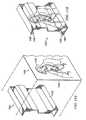
- Figure 5 ais an exploded perspective side view depicting the connection of two side panels 120 by a wedge member 130 of a kit in accordance with one embodiment of the present invention.
- the wedge member 130 showndepicts three pair of T-shaped female slots 132
- the wedge member 130can comprise any combination (number, shape, placement of male/female) of interlocking members.
- an interlocking memberis a male member or a female member. Providing interlocking members as an integral part of the side panels, end panels, and base section allows the interlocking in as many places as is required without the need for a separate weld, nail, screw, nut, bolt, or adhesive.
- the wedge member 130comprises one or more female T-shaped slots.
- the wedge member 130can comprise one or more pairs of T-shaped male protrusions and/or one or more pairs of T-shaped female slots.
- the side panels 120can comprise one or more pairs of T-shaped male protrusions or female slots.
- the T-shaped female slots 132 and T-shaped male protrusions 134 disposed on the side panels 120are tapered.
- the male T-shaped protrusions 134comprise a first distance D1 at the inner portion of the side panel 120 and a second, larger distance D2 at the outer portion of the side panel 120.
- the female T-shaped slots 132comprise a first distance D1 at the inner portion of the female slot 132 and a second, larger distance D2 at the outer portion of the female slot 132.
- the taperingcan be reversed resulting in a second, smaller distance D2.
- the male protrusions 134 and female T-shaped slots 132slidably connect to adjoin the two side panels 120 in a sturdy fashion.
- the wedge 130 and side panelare sized to maximize contact between the outer wedge periphery 131 and a portion of the inner side panel periphery 121.
- Male 136 and female 138 locking memberscan be provided to lock the wedge member 130 into place between the two side panels 120.
- the first side panel 120comprises a plurality of tapered or non-tapered integral alignment protrusions 182 that can be aligned with a plurality of corresponding tapered or non-tapered alignment slots 184 integral to a second side panel 120.
- a locking frame 135 on the wedge member 130can be used to lock the alignment protrusions 182 and alignment slots 184 in place and help absorb any shock loads on the sidewall assembly.
- the wedge member 130permits side panels 120 to be fastened together with virtually no tools. At most, a rubber mallet may be required to force the wedge member 130 into place between the two side panels 120.
- the configuration of the T-shaped protrusions and slotsdistributes any forces or tension placed on the wall joint over a larger area.
- the T-shaped protrusions and slotsprovide a resistance to forces normal to the side panel connection.
- connectionis intuitive to the user, the design facilitates assembly.
- connectioncan be made relatively quickly leading to more efficient casket assembly. Further, such connection is superior to nuts, bolts, screws, or nails because the fastening force is distributed over a larger surface area.
- connectioncan also be disassembled with few or no tools.
- FIG. 5 bis an exploded perspective side view depicting the connection of two side panels 120 by a wedge member 130 of a kit in accordance with an alternative embodiment of the present invention.
- the I-shaped wedge member 130comprises a hollow cylinder comprising a slot 132 in the center of the hollow cylinder.
- the side panel 120comprises a smaller cylindrical protrusion 134 sized such that it can be snugly placed into the slot 132.
- the wedge 130 and an integral portion of the inner side panel periphery 121are sized to maximize contact between the outer wedge periphery 131 and a portion of the inner side panel periphery 121.
- the protrusion 134 and corresponding slot 132can be tapered or non-tapered and may have male or female members (not shown) similar to those identified as numerals 136 and 138 in Figure 4 to help the wedge member snap into place.
- another fastening meansincluding but not limited to a wingnut with or without a washer (not shown), cotter pin or other device can be inserted through the protrusion 134 and slot 132.
- FIG. 5 cis an exploded perspective side view depicting the connection of two side panels 180 by a twist lock fastener in a kit not embodying the present invention.
- each side panel 180can be molded to include a plurality of cam receiving housings 280.
- An aperture 186can be provided adjacent the housing 280 to permit placement of a dowel 284.
- a first side panel 180can comprise a plurality of tapered or non-tapered alignment protrusions 182 that can be aligned with a plurality of corresponding tapered or non-tapered alignment slots 184 integral to a second side panel 180.
- the alignment slots 184 and alignment protrusions 182can help to align the two side panels 180 during assembly.
- the first and second side panels 180can then be pressure-fit and secured together by a twist lock fastener.
- the twist lock fastenercomprises two cams 282 and a dowel 284.
- the dowel 284is placed into a housing 280 and through the aperture 186 such that the dowel 284 resides partially in a housing 280 of each side panel 180.
- a cam 282can then be placed into each housing 280 over the dowel 284 and each cam 282 can then be turned in the direction of the arrow 286 to secure the side panels 180 together.
- cam 282can be configured such that it can be turned with a screwdriver as is depicted in Figure 5 c
- the cam 282in a construction not shown, can also be configured to have an extension similar to a wing nut that can be hand-tightened to help reduce the number of or eliminate all tools required for assembly.
- a single camcan be used with a dowel designed for single cam fastening.
- Figure 6 ais a perspective view showing how the base section can be further secured to a side panel.
- the base section 210slidably connects to the side panel 120 and the clip 240, as depicted in Figure 6 a , can be used merely add support and help secure the connection under heavier loads.
- One or more clips 240can be used to further secure each side of a base end 210 and/or a middle base portion 220 to the side panel 120 and/or the end panel 140.
- one or more clips 240are used at or near joints between the base end 210 and the middle base portion 220. Such configuration is beneficial for several reasons.
- the clips 240permit the side panels 120 to be securely fastened to the base end 210 or middle base portion 220 with no tools.
- the connectionis intuitive to the user, the design facilitates assembly.
- the connectioncan be made relatively quickly leading to more efficient casket assembly.
- the clip 240 mouthis designed to be slightly smaller than the ribs inside a side panel 120 or end panel 140 (not shown) or the base end 210 and/or base portion 220. This enables the clip 240 to pressure-fit onto and retain the ribs of the side panel 120 and portion of the base end 210 and/or base portion 220 to better secure the connection between the side panel 120 and any base section 210 220. Also depicted in Figure 6 a is a side panel handrail receiving member 124 which is discussed in more detail below.
- Figure 6 bis a perspective view depicting a base section.
- a portion 612 of the base section 610is disposed on the side panel ledge 232.
- a stiffening bar 630made of metal or plastic, can be placed into a housing 632 disposed near the side panel ledge 232.
- the housing 632is integral with the side panel 180.
- a joint protrusion 640can be provided to help hold the base section 610 in the proper position during and after assembly.
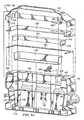
- Figure 7is a perspective view of a partially constructed casket made from a kit in accordance with one embodiment of the present invention.
- one or more side panel handrail receiving members 124are formed integrally with each side panel 120.
- one or more handrail receiving membersare formed integrally with a base section.
- at least one side panel or base sectionfurther comprises one or more handrail receiving members 124 wherein the handrail receiving member is integral to the side panel or base section.
- an integral handrail receiving member 124has greater strength and can withstand a heavier load that a non-integral, fastened handrail receiving member. Another advantage is that the hole in the handrail receiving member can be formed at the same time as the side panel or base section resulting in less assembly to the end-user.
- Figure 8is a perspective view depicting a pallbearer handrail 160 for attachment to the casket of Figure 7 .
- the side panel handrail receiving members 124each comprise a hole for insertion of the handrail 160.
- the handrail 160comprises four separate rails; two long handrails disposed through the handrail receiving members 124 and two shorter handrails adjacent the end panels 140.
- decorative handrail covers 126can be snap-fit over the side panel 120 handrail receiving members 124.
- the decorative handrail covers 126 146 156can comprise any decorative design feature including a cross or other emblem. The long handrails can then be inserted through the holes in the receiving members 124.
- the shorter handrailscan then be inserted through the decorative end panel covers 146 and through the four corner handrail covers 156.
- One advantage of such a configurationis that it permits attachment of a handrail without the use of tools.
- a coupling or corner union (not shown) inside the corner handrail covers 156connects the shorter handrails to the longer handrails.
- Any of the decorative handrail covers 126 146 156can be attached by any number of ways including a snap-fit connection, a fastener connection including a nut or bolt or screw, an adhesive such as double-sided tape, and/or can be held into place by the handrail 160 itself.
- the handrail 160comprises two separate rails adjacent the side panels 120.
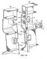
- FIG 9 ais a partial cutaway exploded view of the inside of one end of the casket of Figure 7 .
- Figure 9 bis an exploded perspective view depicting the hinge assembly of the casket of Figure 7 .
- the hinge assembly 400comprises a hinge base 410 slidably connected into a hinge slot 420, wherein the hinge slot 420 is located on the top portion of the side panel 120.
- Two pieces comprising a hinge pin 440can be placed into a receiving hole in the hinge base 410 and press-fit together.
- the entire hinge assembly 400is made from an injection molded plastic.
- One or more hinge pin 440 receiving members 450can be integral to the first lid section 310 and/or second lid section 320.
- screws 435can be used to attach a hinge bracket 430 to the lid 310 320.
- only a screwdriveris needed to attach the hinge assembly 400 to the lid 310 320. Consequently, in one embodiment of the present invention, the casket can be assembled with minimal tools, the only tools potentially necessary being a screwdriver and a rubber mallet.
- the screws 435can be replaced with a screw having a configuration that can permit the hinge to be fastened to the lid 310 320 in a manner that requires no tools.
- a pair of screws 435 having an extension similar to a wing nut that can be hand-tightenedcan be used. In one embodiment, such extension does not exceed the diameter of the head of the screw 435.
- a cotter-pin type fasteneris used.
- some embodiments of the present inventionprovide a kit for a modular casket that requires no tools for assembly.
- FIG 9 cis a partial exploded perspective view depicting the lid assembly of the casket of Figure 7 .
- a lid frame 330can be placed about the inner periphery of the lid 310.
- the lid frame 330can be injection molded such that a plurality of metal heart-shaped clips 314 can be snap-fit onto the lid frame 330, as best shown by Figure 9 a .
- the mouth end of the metal clip 314can engage a corresponding rib on the lid 310 to hold the lid frame 330 in place. Because the metal clip 314 comprises a sharp mouth surface, the mouth surface can grip an adjoining rib.
- a lid framecan similarly be joined to any other lid sections including a second lid section 320.
- Figure 9 dis a partial cutaway view depicting the end of the casket of Figure 7 from the inside.
- the casketcomprises a casket frame 340 and gasket 350 disposed about the outer, upper perimeter of the side panels 120 and end panels 140.
- the casket frame 340can provide aesthetic features such as a lip 342.
- the casket frame 340can be attached to the side panels 120 and end panels 140 by a plurality of metal clips 344 in the same manner that the lid frame is attached to the lid 310 as discussed above.
- a fabriccovers the inside of the side panels 120 and end panels 140.
- the fabriccan be attached to the upper side panels 120 and end panels 140 by the metal clips 344.
- a pan 230is placed in the bottom of the casket.
- a fabric materialmay or may not also cover the pan 230.
- an inflatable air mattressis also placed into the casket to provide the desired elevation of the body in an open casket or other ceremony.
- the gasket 350can be attached by an adhesive.
- a simple arm assembly 360can be attached to the lid locking arm mount 362 and the end panel locking arm mount 364 to prevent the lid from opening too widely. Each of these arm mounts 362 364 can be integrally injection molded with their respective pieces.
- the wingnuts 148used to fasten the decorative end panel handrail cover 146 to the outside of the end panel 140.
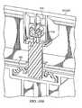
- Figure 10 ais a partial cutaway view of the portion labeled Fig. 10A in Figure 9 a depicting the locking mechanism in accordance with one embodiment of the present invention.
- Figure 10 bis an alternative partial cutaway view depicting the locking mechanism depicted in Figure 10 a .
- a latch assemblycomprises a clip 514, a male latch 510, and a female latch 530.
- the clip 514comprises a raised collar 516 that can be press fit around the cylindrical tip 518 integral to the latch 510.
- the mouth of the clip 514can then be press-fit onto a rib 312 integral to a lid section 310 320.
- a female latch 530can be slidably attached to the top portion of the sidewall 120.
- a male latch ledge 512mates with a female latch ledge 532 after insertion into the female latch 530.
- One advantage of such configurationis that no latches are visible on the outside of the casket. Thus, the latch is not fastened to an outer periphery of the side panel or lid.
- a rigid, flat carde.g. a credit-card like object
- a rigid, flat cardcan be placed between the lid frame 330 and the side panel 120 and can be used to push the male latch 510 inward to permit the lid 310 to open.
- a resilient, rubber-like L-shaped gasket 350is about the upper perimeter of the side panel 120 and the credit card-like object can press a portion of the gasket 350 into the male latch 510 to permit the lid 310 to open.
- the female latch portion 530is attached to the lid 310 320 and the male portion 510 extends from the side panel 120.
- both the female latch 530 and male latch 510can be attached to the lid 310 320 or the side panel 120 by a clip or by a pressure-fit mount.
- the present inventionshould therefore be construed to include all embodiments wherein male 510 or female latch 530 is attached to a lid 310 320, and wherein further said male latch 510 or said female latch 530 removably fastens the lid 310 320 to the side panel 120, wherein said latch assembly is snap-fit together. Another advantage of such configuration is that no tools are required to attach the latch assembly to the side panel 120 or lid 310 320.
- FIG 11is a top perspective view of the casket of Figure 7 .
- the present casketprovides an open casket viewing option.
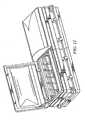
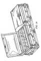
- FIG 12is a simplified perspective view of illustrating the packing configuration of a kit for making a modular casket in accordance with one embodiment of the present invention.
- the various parts of the casketcan be efficiently packaged as a kit in compact form for shipment or storage until partial or full assembly is desired.
- the lid sections 310can be adjacent one another and alternatively nested.
- the side panels 120can be can be grouped together between the lid section 310 and a base pan 230. Nested within the base pan 230 can be one or more nested base sections (not shown).
- Adjacent end panels 140can be oriented perpendicular to the side panels 120 or lid 310.
- the kitcomprises two end panels, two sidewalls and a base section.
- the exemplary packing configuration depicted in Figure 12is for purposes of illustration and not for purposes of limitation. Any compact or efficient shipping configuration can be used that minimizes the storage volume required by a disassembled casket.
- the stored or packaged volume of the casketis approximately 50% less than the assembled volume or volume of the casket when fully assembled.
- the disassembled casket comprising the kit for making the modular casketcan then be placed into a shipping container to protect the casket from damage during shipment.
- imageis defined as a visible design contrast as compared to the color of the molded casket piece prior to the application of a film and encompasses a single solid color in addition to patterns of varying colors.
- the imagecan be applied to a film sheet and the film sheet can then be mated to one or more casket pieces.
- a film sheet having an imageis placed into an injection mold prior to formation of a casket piece through an injection mold process.
- Figure 13 ais a simplified cross-sectional representation of an injection mold having a multi-layer film 1400 prior to the introduction of a molten plastic.
- Figure 13 bis a simplified cross-sectional representation of an injection mold having a multi-layer film 1400 disposed on the exterior 1332 of a molded casket side panel 1320.
- a movable mold 1304 and a stationary mold 1302defines a mold cavity 1310.
- a multi-layer film 1400is placed into the mold cavity 1310.
- the stationary mold 1302then engages the mold cavity 1310 and molten plastic is injected into the mold cavity 1310 through injection ports (not shown) to form a molded casket part, such as a casket side panel 1320, that corresponds to the shape of the mold and having a multi-layer film 1400 with an image disposed on the casket exterior 1332.
- the molded casket partis then cooled to solidify the casket part 1320.
- the multi-layer film 1400becomes embedded in the exterior 1332 of the casket side panel 1320.
- the multi-layer film 1400terminates at the terminal end of the casket piece 1320.
- the movable mold 1304opens by moving in the general direction depicted by the arrows and the solidified casket part 1320 is then removed from the mold cavity 1310.
- the multi-layer film 1400terminates not at the terminal end of the casket piece, but within the molded plastic piece by design.
- a methodcan be used, for example, to provide a two-tone color scheme - the first color can be provided by the injected plastic and the second color can be provided by the film.
- the filmwhich can comprise a multi-layer or laminate film 1400 comprises an image.
- Figure 14is a schematic cross of a prior art multi-layer film 1400.
- the imagecan be provided as by an ink layer 1420 on a multi-layer film.
- the multi-layer filmcomprises a transparent polymer protective layer 1410 having an ink graphic 1420 layer and an optional adhesive layer 1430.
- Such filmsare well known in the art.
- the image 1420can be reverse printed onto a Acrylonitrile Butadiene Styrene (ABS), glycol modified polyethylene terephthlate (PETg) 1410 or other suitable film 1410 by any suitable graphics application method.
- ABSAcrylonitrile Butadiene Styrene
- PETgglycol modified polyethylene terephthlate
- a holographic imageis printed using a metallic ink.
- the metallic inkis modified by a laser.
- the optional adhesive layer 1430can be applied over the ink layer 1420 by extrusion alone or by lamination.
- the above example of a multi-layer film having an imageis for purposes of illustration and not limitation. Any monolayer or multi-layer film that can be applied and/or embedded onto a casket piece can be used. Further, in one method, a transparent film is applied to a casket piece as a layer of protection for the casket.
- the method of placing the pre-made image onto the casket piececan be achieved in numerous ways well known in the art including, but not limited to, non-structural applique, vacuum thermoforming, and dipping.
- Figure 15 adepicts an exploded perspective view of a multi-layer film 1400 having an image 1420 of the Virgin of Guadalupe and a portion of a solidified casket side panel 1520 having an exterior 1532.
- the entire film sheet 1400is heated so that when the sheet is subsequently delivered to a forming station (not shown), an overall temperature balance has been attained.
- the sheetis conveyed to the forming station where by one of several methods it is forced over and contoured onto the casket piece 1520, as shown in Figure 15 b .
- thermoforming of the sheet onto the casket partcan be performed by means of different, conventional techniques, for instance, in vacuum thermoforming, a pre-cut sheet of multi-layer film sheet 1400 having an image 1420 is heated.
- a vacuumcan be applied to remove the air between the multi-layer film sheet 1400 and the casket piece 1520 and/or a counter mold can be used to help force the sheet onto the casket piece 1520.
- the residual heat on the film sheet 1400can be removed after forming.
- the end productis removed from the forming station and sent to a trim press where the end product is trimmed from the web.
- the adhesive layer 1430bonds the multi-layer film onto the casket exterior 1532.
- the image 1420may be printed onto the multi-layer film in a way that adjusts for distortion that will occur when the image is contoured onto the casket piece 1520.
- the adjustment for distortioncan be made as follows.
- the imageis first developed as a standard flat graphic.
- a sheetthe same size as the production sheet with a grid pattern printed on it is formed over the actual part (or representation of the part) to create a formed grid.
- the grid locations of the formed grid sheetare matched to the original flat graphic.
- the points on the flat graphicare moved using standard imaging software to a new location opposite the movement seen in the formed grid.
- the resultis a new final graphic that when formed over the casket part shows no distortion of the graphic regardless of the graphic used. Consequently, there is provided a way to compensate for distortion and results in a distrotionless graphic.
- a trap-forming processis used to apply the film to a casket part.
- Figure 13 cis a simplified cross-sectional representation depicting the trap forming process.
- Figure 13 dis a partial blown-up view of Figure 13c depicting the terminal end of the multi-layer film 1400.
- a sheet of film or film sheet 1400comprising a suitable resin, polymer, or similar material is heated in one method to the point where the sheet is malleable.
- the filmis not heated and comprises a pressure sensitive adhesive layer 1430.
- the sheetis then lowered onto a molded casket part 1320.
- the edges of the sheet 1400are pulled down around the periphery of the casket part until contact with the terminal ends 1322 of the casket part 1320 is made.
- the sheet 1400stretches and conforms to the casket part only to the extent of the pulling of the sheet 1400 down.
- a box 1303 having a box interior 1305roughly the size of the exterior 1332 dimension of the casket part 1320 engages and pushes the edges of the sheet against the casket part on the casket part exterior 1332 perimeter.
- the sheet 1400curls 1480 around the terminal edge 1322 of the casket part 1320.
- Figure 15 billustrates this in a perspective view.
- the excess 1490 of the sheet 1400can then be trimmed off leaving a clean edge that is unseen to the end user.
- the trap forming process described abovecan be particularly useful to apply an image to a casket part made from any material including wood or a metal such as steel.
- the multi-layer film 1400comprises semi-curled 1480 terminal ends to ensure the multi-layer film 1400 completely covers the entire exterior 1332 of the molded casket piece to prevent one from discerning the distinction between the film 1400 and the base plastic 1332.
- the multi-layer film terminal endwraps around at least a portion of the terminal end 1322 of the casket part 1320. Such a method advantageously provides greater holding power of the film 1400 to the casket part 1320 and provides greater aesthetic appeal. The remaining section 1490 of the film can then be removed.
- Figure 16is a perspective view of a casket attempting to illustrate a stone faux finish and made from a kit in accordance with one embodiment of the present invention.
- the image of stone faux finishis provided by the multilayer film. While Figure 16 is a somewhat crude attempt at showing a casket having a stone faux finish, those skilled in the art, armed with this disclosure, will recognize that the beauty that can be imparted to a casket by a faux stone finish is difficult to overstate.
- the stone faux finish imagecan mimic one or more desirable stone images such as granite, marble, limestone, travertine, and breccia. There is thereby provided a method for making caskets with a whole new dimension that is not present available. Making a casket out of stone is prohibitively difficult.
- the imagecomprises one or more patriotic symbols such as a flag, or symbols of the armed forces.
- the imagemimics a wood finish to less expensively provide the look of a wooden coffin.
- the imagemimics a steel finish to less expensively provide the look of a steel casket.
- the imagecomprises one or more colors to less expensively provide the look of a painted casket.
- these imagescan be configured through properly registering the image on the film with the corresponding casket piece such that when the modular casket pieces are assembled into the casket, two or more casket parts reveal a single complementary image in a way similar to that of a jigsaw puzzle.
- the casketcan mimic the appearance of a flag-draped casket.
- the imagecomprises a holographic image.
- Holographic film laminatesare known in the art as exemplified by U.S. Pat. Nos. 4,971,646 and 5,200,253 .
- the holographic imagerequires one to focus on the image before the image becomes apparent.
- the holographic imagemay be printed onto the thin plastic film by with a metallic ink.
- the holographic imagemay be printed by a metallic ink on a thin plastic film.
- the holographic imagesmay be created by using a laser that permits light to be diffracted in multiple directions giving the viewer the ability to see two images in one location.
- the imagecomprises one or more lenticular images.
- a lenticular imageis defined as an image that shows depth or motion as the viewing angle changes.
- Lenticular film laminatesare known in the art as exemplified by U.S. Pat. No. 6,373,636 .
- the imagecomprises one or more two-dimensional or three-dimensional religious symbols such as the Pope John Paul, the Virgin Mary, the Virgin of Guadalupe, a cross, Jesus, etc.
- a casket having a holographic or lenticular imagecan impart a special atmosphere to participants to a solemn funeral service when images such as religious images appear on the casket. There is therefore provided a way to convey symbolic meaning in a tasteful manner during a solemn occasion.
- the present inventionprovides numerous advantages over the prior art.
- plastic caskets made using kits of the present inventionare less expensive to fabricate than the traditional wood or steel caskets.
- the casketcan be easily shipped as a more compact set of parts than a traditional wood or steel casket, or a non-modular casket fabricated from other materials.
- a plastic casket made using a kit of the present inventionis not only less expensive to ship, but easier to handle, both in unassembled and assembled form. Further, the casket can be easily moved and stored.
- the kit according to the present inventionallows a casket to be quickly and easily constructed and assembled by a funeral home or by an individual with little or no assembly experience.
- the only tools that may be requiredinclude a rubber mallet and a screwdriver.
- the assembly of the snap-fit and pressure-fit piecesis intuitive in the way in which the pieces are put together.
- Such advantagescan be useful in areas of natural disasters.
- Such advantagealso provides the ability to direct-market the casket to consumers through a phone number or web-site without the added expense of a middle man.
- the casketcan be marketed to consumers through stores by-passing the traditional funeral home and resultant mark-up.
- the casketmay be made of materials that are more durable than the prior art caskets. For example, unlike wood, plastic does not swell or deform. Unlike metal, plastic does not rust or dent. Further, when a kit according to the present invention is packed, it can be shipped without worry of exposure to the elements. For example, the kit of the present invention can be stored outside with worry of exposure to the elements including, but not limited to temperature, humidity, moisture, blowing sand, etc. Such advantage can be useful in areas of natural disasters. Wood, on the other hand, must be stored in controlled climate conditions. Similarly, metal-type caskets, if subjected to high humidity or moisture conditions, are susceptible to rust, especially if any scratches were made through the painted metal during shipment. Thus, the present invention may provide a kit that is more durable under both shipping and storage conditions.
- the casketcan be made to emulate the caskets of wood design or steel designs.
- a wood grain finishcan be imparted into the injection molded plastic.
- rounded corners used in wood casketscan be provided in kits according to the present invention.
- the color of the plasticcan be easily changed to emulate steel-type colors.
- the kit of the present inventionmay have the same accessories as caskets of the prior art. Consequently, the present invention may provide a kit for making a casket having a similar look and design as prior art caskets with lower costs. Thus, there is little or no stigma attached to using a casket made from less expensive plastic materials of a kit according to the present invention.
Landscapes
- Health & Medical Sciences (AREA)
- Life Sciences & Earth Sciences (AREA)
- Animal Behavior & Ethology (AREA)
- General Health & Medical Sciences (AREA)
- Public Health (AREA)
- Veterinary Medicine (AREA)
- Rigid Containers With Two Or More Constituent Elements (AREA)
- Mirrors, Picture Frames, Photograph Stands, And Related Fastening Devices (AREA)
- Securing Of Glass Panes Or The Like (AREA)
- Steps, Ramps, And Handrails (AREA)
- Connection Of Plates (AREA)
- Injection Moulding Of Plastics Or The Like (AREA)
Description
- The present invention relates to a kit for making a modular casket and, in one aspect, to a kit for making a modular casket having an integral image.
- Caskets or coffins are typically purchased during a stressful time shortly after the unfortunate need arises due to the death of a loved one. Although caskets have been traditionally purchased through a funeral home, caskets could be more available from alternative point of sale locations such as directly from a funeral supply stores, the internet, and retail locations. The available selection of caskets, however, is mostly limited to steel or wood caskets that are expensive. The bulky steel or wood caskets are also difficult to ship and prone to damage during shipment which increases the difficulty of using alternative point of sale locations. Caskets also occupy considerable space when stored and require climate controlled storage. Consequently, a need exists for a less expensive casket. A need also exists for a modular casket that can be easily shipped and assembled and can be stored in a non-climate controlled facility.
- Further, the steel or wood caskets typically have a single, mono-tone color. For example, wood caskets often have a wood-looking, brown exterior. Steel caskets often have a single steel-like color such as gray or silver. Application of exterior finishes typically occurs after the casket piece has been manufactured. Consequently, the addition of different designs to a steel or wood casket through application of a stain, primer, paint, lacquer, or other similar coating can be labor-intensive and therefore expensive to apply and such finishes are highly prone to damage during shipment and storage. Further, as the complexity of the design increases, the cost substantially increases. This is one reason that caskets typically have only single-color, monotone exteriors. Consequently, a need exists for a method of making a casket that incorporates one or more pre-made images, such as a color or design, to the casket exterior during or after the manufacturing process.
- Prior art attempts have been made to decorate casket exteriors. For example,
U.S. Patent No. 1,388,426 discloses a method of decorating the surface of a casket. The method involves a time-consuming labor-intensive process. U.S. Patent No. 6,223,404 discloses a casket with a customized, decorative external surface and methods in which panels of an adhesive-backed substrate material with a digitally imaged design are fixed to the casket surface. This method also requires a time-consuming labor-intensive process including the steps of applying an acid-wash neutralizer to the external surface of the casket, buffing the surface, applying a primer, and finally applying the substrate material. The method also heavily emphasizes the complicated step of supplying a two-dimensional image that can be placed on a three-dimensional casket.U.S. Patent No. 6,018,853 , on which the pre-characterising portion ofclaim 1 is based, discloses a knockdown coffin structure.U.S. Patent No. 5,771,548 discloses a flat-lid casket.GB247120 - The present invention provides a kit for making a modular casket, the kit being as defined in
claim 1. - Optional features are recited in the dependent claims.
- In one embodiment, each end panel has a pair of vertical end panel sides wherein a vertical side of each side panel is slidably attachable to a vertical end panel side. In one embodiment, the modular casket comprises a base section slidably attachable to said opposed side panels and to said opposed end panels, wherein said base section and each of said side panels and end panels comprises an injection molded composition.
- The above as well as additional features and advantages of the present invention will become apparent in the following written detailed description.
- A more complete understanding of the present invention may be had by reference to the following detailed description when taken in conjunction with the accompanying drawings, wherein:
Figure 1 is a top perspective view of a casket made from a kit in accordance with one embodiment of the present invention.Figure 2 is a bottom perspective view of the casket ofFigure 1 .Figure 3 is an overall exploded perspective view of the casket ofFigure 1 .Figure 4 is a partial cutaway detailed view depicting the connection between a side panel, an end panel, and a base section of a kit in accordance with one embodiment of the present invention.Figure 5 a is an exploded perspective side view depicting the connection of two side panels by a wedge member of a kit in accordance with one embodiment of the present invention.Figure 5 b is an exploded perspective side view depicting the connection of two side panels by a wedge member of a kit in accordance with an alternative embodiment of the present invention.Figure 5 c is an exploded perspective side view depicting the connection of two side panels by a twist lock fastener.Figure 6 a is a perspective view showing how the base section can be further secured to a side panel.Figure 6 b is a perspective view depicting a base section.Figure 7 is a perspective view of a partially constructed casket made from a kit in accordance with one embodiment of the present invention.Figure 8 is a perspective view depicting a pallbearer handrail for attachment to the casket ofFigure 7 .Figure 9 a is a partial cutaway exploded view of the inside of one end of the casket ofFigure 7 .Figure 9 b is an exploded perspective view depicting the hinge assembly of the casket ofFigure 7 .Figure 9c is a partial exploded perspective view taken depicting the lid assembly of the casket ofFigure 7 .Figure 9 d is a partial cutaway view depicting the end of the casket ofFigure 7 from the inside.Figure 10 a is a partial cutaway view of the portion labeledFig. 10A inFigure 9 a depicting the locking mechanism.Figure 10 b is an alternative partial cutaway view depicting the locking mechanism depicted inFigure 10 a.Figure 11 is a top perspective view of the casket ofFigure 7 .Figure 12 is a simplified perspective view illustrating the packing configuration of a kit for making a modular casket in accordance with one embodiment of the present invention.Figure 13 a is a simplified cross-sectional representation of an injection mold having a multi-layer film.Figure 13 b is a simplified cross-sectional representation of an injection mold having a multi-layer film disposed on the exterior of a casket side panel.Figure 13 c is a simplified cross-sectional representation depicting the trap forming process.Figure 13 d is a partial blown-up view ofFigure 13 c depicting the terminal end of the multi-layer film.Figure 14 is a schematic cross-section of a prior art multi-layer film.Figure 15 a depicts an exploded perspective view of a multi-layer film having an image of the Virgin of Guadalupe and a portion of a solidified casket side panel having an exterior.Figure 15 b is a perspective view of a portion of a casket side panel having an image of the Virgin of Guadalupe; andFigure 16 is a perspective view of a casket attempting to illustrate a stone faux finish and made from a kit in accordance with one embodiment of the present invention.- Where used in the various figures of the drawing, the same numerals designate the same or similar parts. Furthermore, when the terms "top," "bottom," "first," "second," "upper," "lower," "height," "width," "length," "end," "side," "horizontal," "vertical," and similar terms are used herein, it should be understood that these terms have reference only to the structure shown in the drawing and are utilized only to facilitate describing the invention.
Figure 1 is a top perspective view of a casket made from a kit in accordance with one embodiment of the present invention. As used herein, the term "casket" is synonymous with and meant to include the term "coffin."Figure 2 is a bottom perspective view of the casket.Figure 3 is an overall exploded perspective view of the casket. Referring toFigure 3 , the casket comprises a pair ofopposed sidewalls 110. The same reference numbers are used to identify the same corresponding elements throughout all drawings unless otherwise noted. Thesidewalls 110 comprise one ormore side panels 120. Eachsidewall 110 comprises a pair ofside panels 120 slidably connected together by awedge member 130. Eachside panel 120 comprises a vertical side 122 designed to be slidably attached to a verticalend panel side 141 142. It should be pointed out that the "vertical" end panel sides141 142 do not need to be vertical and such sides can be rounded. The term "vertical" is simply used to denote the side141142 of theend panel 140 that is attached to theside panel 120. Similarly, the vertical side122 of theside panel 120 can be rounded or any other shape and is simply called "vertical" to denote the side122 of theside panel 120 that is attached to theend panel 140. The base section can comprise one or more pieces. In one embodiment, the base section comprises two base ends210 and amiddle base portion 220. The base section can be attached to theopposed side panels 120 and/or saidopposed end panels 140.- The lid can comprise one or more sections. In one embodiment, a
first lid section 310 and asecond lid section 320 can be attached to thesidewall 110. In one embodiment, thefirst lid section 310 is attached to afirst side panel 120 and thesecond lid section 320 is attached to an adjacentsecond side panel 120. - The base section, side walls, end panels, and lid can comprise a plastic composition. Although the base section, side walls, end panels, and lid components and the hinge assembly can be formed from a variety of different materials using different manufacturing techniques, in one embodiment, they are injection molded from a suitable plastic containing fibers for reinforcement. Plastics that can be used include, but are not limited to ABS, polycarbonate, fiberglass, metals, and mixtures thereof. Any injection molded composition can be used. As used herein, an "injection molded composition" is defined as any material, resin or composite that can be injection molded. It should be further noted that different additives can be used for different injection molded parts. Strengthening ribs and other complex structures can be provided to make the components more rigid.
- As shown in
Figure 3 , eachside panel 120 comprises one rounded edge near theend panel 140. Such illustration is just one example of how a rounded corner can be provided. In one embodiment (not shown), the end panel comprises one or more rounded corners. In one embodiment (not shown), a side panel comprises a rounded corner. Some consumers deem rounded corners to be desirable in caskets and caskets having rounded corners are more expensive to manufacture and are consequently more expensive in the marketplace. For example, the expenses of making a metal or steel casket with a rounded edge are significant because of the forming/stamping/pressing operation that is required to form the metal or steel material. Such forming equipment is expensive. Consequently, steel and metal caskets are typically cut to length and welded together to form square corners. However, caskets made of sheet metal are still labor intensive because of the welding and grinding that is required in putting the caskets together. Wood caskets more typically have rounded corners, but wood is relatively heavy, bulky, and expensive to ship. Both metal and wood caskets, if not assembled prior to shipment, are difficult to assemble at a point of distribution or use, unlike the present invention, which is easy to assemble for reasons discussed in more detail below. Figure 4 is a partial cutaway detailed view depicting the connection between aside panel 120, anend panel 140, and abase section 210 in accordance with one embodiment of the present invention. In the embodiment shown, theend panel 140 is sized to be slidably connected into theside panel 120 receivingcavity 128. As used herein the term "slidably connected" and the term "slidably attached" is defined by the attachment or connection of two pieces such that the pieces are pressure-fit together. "Pressure-fit," is a term known to those skilled in the art. The term can refer to a bond caused by mutual pressure acting on the contact surfaces between two parts in contact, wherein the two parts require no weld, screw, or nail connection. Thus, in one embodiment, theside panel 120 and receivingcavity 128 are sized to maximize the contact between theside panel 120 outer periphery and receivingcavity 128 inner periphery. In addition, amale member 136 on theend panel 140 is located so as to snap-fit into afemale member 138 located on theside panel 120. Such members136138 help to further lock the two pieces together and secure the two pieces in place. Such members not only help hold the two pieces together, but they also further signal the assembler that the connection is complete. It should be pointed out that this specific connection is provided for purposes of illustration and not limitation. There can be any number of male and female pairs in any configuration. For example, in an embodiment not shown, similar male and female members are provided on thebase section 210 andend panel 140 to further lock theend panel 140 andbase section 210 together and/or signal the assembler that the connection is complete. In one embodiment not shown, similar male and female members are provided on the base section and side panel for similar reasons.- It should also be pointed out that the panels can be designed such that a side panel is sized to be slidably connected to an end panel receiving cavity (not shown). Such embodiment can occur if the
end panel 140 is rounded and theside panel 120 is flat at the corner connection. - As shown in
Figure 4 , in one embodiment, thebase end 210 comprises L-shaped female sidepanel interlocking members 229 that can slidably connect to an L-shaped male sidepanel locking member 129. Similarly, thebase end 210 comprises an L-shaped female endpanel interlocking member 249 that can slidably connect to an L-shaped male endpanel locking member 149. It should be pointed out that while the embodiment depicted and discussed with reference toFigure 4 is directed towards L-shaped slots, any shape (tapered or untapered, L-shaped, T-shaped, etc.), number, and combination (male member on base and female on panel or female on panel and male on base) of interlocking-shaped members that can be used to slidably connect thebase section 210 to theside panel 120 and/orend panel 140 does not depart from the scope of the present invention. Figure 5 a is an exploded perspective side view depicting the connection of twoside panels 120 by awedge member 130 of a kit in accordance with one embodiment of the present invention. Although thewedge member 130 shown depicts three pair of T-shapedfemale slots 132, thewedge member 130 can comprise any combination (number, shape, placement of male/female) of interlocking members. In one aspect, an interlocking member is a male member or a female member. Providing interlocking members as an integral part of the side panels, end panels, and base section allows the interlocking in as many places as is required without the need for a separate weld, nail, screw, nut, bolt, or adhesive. In one embodiment, thewedge member 130 comprises one or more female T-shaped slots. Further, thewedge member 130 can comprise one or more pairs of T-shaped male protrusions and/or one or more pairs of T-shaped female slots. Similarly, theside panels 120 can comprise one or more pairs of T-shaped male protrusions or female slots. In one embodiment the T-shapedfemale slots 132 and T-shapedmale protrusions 134 disposed on theside panels 120 are tapered. Thus, in one embodiment, the male T-shapedprotrusions 134 comprise a first distanceD1 at the inner portion of theside panel 120 and a second, larger distanceD2 at the outer portion of theside panel 120. Similarly, in one embodiment, the female T-shapedslots 132 comprise a first distanceD1 at the inner portion of thefemale slot 132 and a second, larger distanceD2 at the outer portion of thefemale slot 132. Of course, the tapering can be reversed resulting in a second, smaller distanceD2. Themale protrusions 134 and female T-shapedslots 132 slidably connect to adjoin the twoside panels 120 in a sturdy fashion. In one embodiment, thewedge 130 and side panel are sized to maximize contact between theouter wedge periphery 131 and a portion of the innerside panel periphery 121.Male 136 and female138 locking members can be provided to lock thewedge member 130 into place between the twoside panels 120.- The
first side panel 120 comprises a plurality of tapered or non-taperedintegral alignment protrusions 182 that can be aligned with a plurality of corresponding tapered ornon-tapered alignment slots 184 integral to asecond side panel 120. A lockingframe 135 on thewedge member 130 can be used to lock thealignment protrusions 182 andalignment slots 184 in place and help absorb any shock loads on the sidewall assembly. - The above-described configuration is beneficial for several reasons. First, the
wedge member 130 permitsside panels 120 to be fastened together with virtually no tools. At most, a rubber mallet may be required to force thewedge member 130 into place between the twoside panels 120. Second, the configuration of the T-shaped protrusions and slots distributes any forces or tension placed on the wall joint over a larger area. Third, because the T-shaped protrusions and slots are oriented parallel to any normal forces exerted on the panels, e.g. forces that are perpendicular to the plane of the side panels, a sturdy connection can be made at the joint between the twoside panels 120. Thus, the T-shaped protrusions and slots provide a resistance to forces normal to the side panel connection. Fourth, because the connection is intuitive to the user, the design facilitates assembly. Fifth, because no screws or nails are required, the connection can be made relatively quickly leading to more efficient casket assembly. Further, such connection is superior to nuts, bolts, screws, or nails because the fastening force is distributed over a larger surface area. Sixth, the connection can also be disassembled with few or no tools. - While several embodiments discussed above are directed towards T-shaped protrusions and slots, any type and number of tapered or non-tapered interlocking-shaped members can be used to slidably connect two
side panels 120 together with awedge member 130 without departing from the scope of the present invention. For example,Figure 5 b is an exploded perspective side view depicting the connection of twoside panels 120 by awedge member 130 of a kit in accordance with an alternative embodiment of the present invention. Referring toFigure 5 b, the I-shapedwedge member 130 comprises a hollow cylinder comprising aslot 132 in the center of the hollow cylinder. Theside panel 120 comprises a smallercylindrical protrusion 134 sized such that it can be snugly placed into theslot 132. In one embodiment, thewedge 130 and an integral portion of the innerside panel periphery 121 are sized to maximize contact between theouter wedge periphery 131 and a portion of the innerside panel periphery 121. Theprotrusion 134 andcorresponding slot 132 can be tapered or non-tapered and may have male or female members (not shown) similar to those identified asnumerals Figure 4 to help the wedge member snap into place. Further, in one embodiment, another fastening means including but not limited to a wingnut with or without a washer (not shown), cotter pin or other device can be inserted through theprotrusion 134 andslot 132. - Further, other ways of fastening the side panels with minimal use of tools can also be provided without departing from the scope of the present invention.
Figure 5 c is an exploded perspective side view depicting the connection of twoside panels 180 by a twist lock fastener in a kit not embodying the present invention. As shown inFigure 5 c, eachside panel 180 can be molded to include a plurality ofcam receiving housings 280. Anaperture 186 can be provided adjacent thehousing 280 to permit placement of adowel 284. Afirst side panel 180 can comprise a plurality of tapered ornon-tapered alignment protrusions 182 that can be aligned with a plurality of corresponding tapered ornon-tapered alignment slots 184 integral to asecond side panel 180. Thealignment slots 184 andalignment protrusions 182 can help to align the twoside panels 180 during assembly. The first andsecond side panels 180 can then be pressure-fit and secured together by a twist lock fastener. In the construction shown, the twist lock fastener comprises twocams 282 and adowel 284. Thedowel 284 is placed into ahousing 280 and through theaperture 186 such that thedowel 284 resides partially in ahousing 280 of eachside panel 180. Acam 282 can then be placed into eachhousing 280 over thedowel 284 and eachcam 282 can then be turned in the direction of thearrow 286 to secure theside panels 180 together. Although thecam 282 can be configured such that it can be turned with a screwdriver as is depicted inFigure 5 c, thecam 282, in a construction not shown, can also be configured to have an extension similar to a wing nut that can be hand-tightened to help reduce the number of or eliminate all tools required for assembly. In one construction, a single cam can be used with a dowel designed for single cam fastening.Figure 6 a is a perspective view showing how the base section can be further secured to a side panel. As depicted inFigure 4 , thebase section 210 slidably connects to theside panel 120 and theclip 240, as depicted inFigure 6 a, can be used merely add support and help secure the connection under heavier loads. One ormore clips 240 can be used to further secure each side of abase end 210 and/or amiddle base portion 220 to theside panel 120 and/or theend panel 140. In one construction, one ormore clips 240 are used at or near joints between thebase end 210 and themiddle base portion 220. Such configuration is beneficial for several reasons.- First, the
clips 240 permit theside panels 120 to be securely fastened to thebase end 210 ormiddle base portion 220 with no tools. Second, because the connection is intuitive to the user, the design facilitates assembly. Third, because no screws or nails are required, the connection can be made relatively quickly leading to more efficient casket assembly. - In one construction, the
clip 240 mouth is designed to be slightly smaller than the ribs inside aside panel 120 or end panel140 (not shown) or thebase end 210 and/orbase portion 220. This enables theclip 240 to pressure-fit onto and retain the ribs of theside panel 120 and portion of thebase end 210 and/orbase portion 220 to better secure the connection between theside panel 120 and anybase section 210 220. Also depicted inFigure 6 a is a side panelhandrail receiving member 124 which is discussed in more detail below. Figure 6 b is a perspective view depicting a base section. Aportion 612 of thebase section 610 is disposed on theside panel ledge 232. A stiffeningbar 630, made of metal or plastic, can be placed into ahousing 632 disposed near theside panel ledge 232. In one construction, thehousing 632 is integral with theside panel 180. Ajoint protrusion 640 can be provided to help hold thebase section 610 in the proper position during and after assembly.Figure 7 is a perspective view of a partially constructed casket made from a kit in accordance with one embodiment of the present invention. In one embodiment, one or more side panelhandrail receiving members 124 are formed integrally with eachside panel 120. In an alternative embodiment (not shown), one or more handrail receiving members are formed integrally with a base section. Thus, in one embodiment, at least one side panel or base section further comprises one or morehandrail receiving members 124 wherein the handrail receiving member is integral to the side panel or base section. One advantage of an integralhandrail receiving member 124 is that forces imparted through the hole to thehandrail receiving member 124 by a handrail are spread more evenly over a larger area than would occur if thehandrail receiving member 124 were attached by some type of fastener. Consequently, an integralhandrail receiving member 124 has greater strength and can withstand a heavier load that a non-integral, fastened handrail receiving member. Another advantage is that the hole in the handrail receiving member can be formed at the same time as the side panel or base section resulting in less assembly to the end-user.Figure 8 is a perspective view depicting apallbearer handrail 160 for attachment to the casket ofFigure 7 . Referring toFigure 7 andFigure 8 , the side panelhandrail receiving members 124 each comprise a hole for insertion of thehandrail 160. In one embodiment, thehandrail 160 comprises four separate rails; two long handrails disposed through thehandrail receiving members 124 and two shorter handrails adjacent theend panels 140. Once the casket inFigure 7 has been constructed, decorative handrail covers126 can be snap-fit over theside panel 120handrail receiving members 124. The decorative handrail covers126 146 156 can comprise any decorative design feature including a cross or other emblem. The long handrails can then be inserted through the holes in the receivingmembers 124. The shorter handrails can then be inserted through the decorative end panel covers146 and through the four corner handrail covers156. One advantage of such a configuration is that it permits attachment of a handrail without the use of tools. A coupling or corner union (not shown) inside the corner handrail covers156 connects the shorter handrails to the longer handrails. Any of the decorative handrail covers126 146 156 can be attached by any number of ways including a snap-fit connection, a fastener connection including a nut or bolt or screw, an adhesive such as double-sided tape, and/or can be held into place by thehandrail 160 itself. In one embodiment, thehandrail 160 comprises two separate rails adjacent theside panels 120.Figure 9 a is a partial cutaway exploded view of the inside of one end of the casket ofFigure 7 .Figure 9 b is an exploded perspective view depicting the hinge assembly of the casket ofFigure 7 . Referring toFigures 9 a and9b, thehinge assembly 400 comprises ahinge base 410 slidably connected into ahinge slot 420, wherein thehinge slot 420 is located on the top portion of theside panel 120. Two pieces comprising ahinge pin 440 can be placed into a receiving hole in thehinge base 410 and press-fit together. In one embodiment, theentire hinge assembly 400 is made from an injection molded plastic. One ormore hinge pin 440 receivingmembers 450 can be integral to thefirst lid section 310 and/orsecond lid section 320. In one embodiment, screws435 can be used to attach ahinge bracket 430 to thelid 310 320. In one embodiment, only a screwdriver is needed to attach thehinge assembly 400 to thelid 310 320. Consequently, in one embodiment of the present invention, the casket can be assembled with minimal tools, the only tools potentially necessary being a screwdriver and a rubber mallet. It should also be pointed out that thescrews 435 can be replaced with a screw having a configuration that can permit the hinge to be fastened to thelid 310 320 in a manner that requires no tools. For example, a pair ofscrews 435 having an extension similar to a wing nut that can be hand-tightened can be used. In one embodiment, such extension does not exceed the diameter of the head of thescrew 435. In one embodiment, a cotter-pin type fastener is used. Thus, some embodiments of the present invention provide a kit for a modular casket that requires no tools for assembly.Figure 9 c is a partial exploded perspective view depicting the lid assembly of the casket ofFigure 7 . Referring toFigures 9 a and9c, alid frame 330 can be placed about the inner periphery of thelid 310. Thelid frame 330 can be injection molded such that a plurality of metal heart-shapedclips 314 can be snap-fit onto thelid frame 330, as best shown byFigure 9 a. The mouth end of themetal clip 314 can engage a corresponding rib on thelid 310 to hold thelid frame 330 in place. Because themetal clip 314 comprises a sharp mouth surface, the mouth surface can grip an adjoining rib. A lid frame can similarly be joined to any other lid sections including asecond lid section 320.Figure 9 d is a partial cutaway view depicting the end of the casket ofFigure 7 from the inside. Referring toFigures 9 a and9d, in one embodiment, the casket comprises acasket frame 340 andgasket 350 disposed about the outer, upper perimeter of theside panels 120 and endpanels 140. Thecasket frame 340 can provide aesthetic features such as alip 342. Thecasket frame 340 can be attached to theside panels 120 and endpanels 140 by a plurality ofmetal clips 344 in the same manner that the lid frame is attached to thelid 310 as discussed above.- In one embodiment, a fabric covers the inside of the
side panels 120 and endpanels 140. The fabric can be attached to theupper side panels 120 and endpanels 140 by the metal clips344. In one embodiment, apan 230 is placed in the bottom of the casket. A fabric material may or may not also cover thepan 230. In one embodiment an inflatable air mattress is also placed into the casket to provide the desired elevation of the body in an open casket or other ceremony. Thegasket 350 can be attached by an adhesive. Asimple arm assembly 360 can be attached to the lid lockingarm mount 362 and the end panel lockingarm mount 364 to prevent the lid from opening too widely. Each of these arm mounts362 364 can be integrally injection molded with their respective pieces. Also shown inFigure 9 d are thewingnuts 148 used to fasten the decorative endpanel handrail cover 146 to the outside of theend panel 140. Figure 10 a is a partial cutaway view of the portion labeledFig. 10A inFigure 9 a depicting the locking mechanism in accordance with one embodiment of the present invention.Figure 10 b is an alternative partial cutaway view depicting the locking mechanism depicted inFigure 10 a. Referring toFigures 10 a and10b, in one embodiment, a latch assembly comprises aclip 514, amale latch 510, and afemale latch 530. In one embodiment, theclip 514 comprises a raisedcollar 516 that can be press fit around thecylindrical tip 518 integral to thelatch 510. In one embodiment, the mouth of theclip 514 can then be press-fit onto arib 312 integral to alid section 310 320. Afemale latch 530 can be slidably attached to the top portion of thesidewall 120. Amale latch ledge 512 mates with afemale latch ledge 532 after insertion into thefemale latch 530. One advantage of such configuration is that no latches are visible on the outside of the casket. Thus, the latch is not fastened to an outer periphery of the side panel or lid.- To open, a rigid, flat card (e.g. a credit-card like object) can be placed between the
lid frame 330 and theside panel 120 and can be used to push themale latch 510 inward to permit thelid 310 to open. In one embodiment a resilient, rubber-like L-shapedgasket 350 is about the upper perimeter of theside panel 120 and the credit card-like object can press a portion of thegasket 350 into themale latch 510 to permit thelid 310 to open. - One skilled in the art would recognize that such feature could be reversed and in one embodiment the
female latch portion 530 is attached to thelid 310 320 and themale portion 510 extends from thesidepanel 120. Similarly, one skilled in the art would recognize that both thefemale latch 530 andmale latch 510 can be attached to thelid 310 320 or theside panel 120 by a clip or by a pressure-fit mount. The present invention should therefore be construed to include all embodiments wherein male510 orfemale latch 530 is attached to alid 310 320, and wherein further saidmale latch 510 or saidfemale latch 530 removably fastens thelid 310 320 to theside panel 120, wherein said latch assembly is snap-fit together. Another advantage of such configuration is that no tools are required to attach the latch assembly to theside panel 120 orlid 310 320. Figure 11 is a top perspective view of the casket ofFigure 7 . Like traditional caskets, the present casket provides an open casket viewing option.Figure 12 is a simplified perspective view of illustrating the packing configuration of a kit for making a modular casket in accordance with one embodiment of the present invention. As shown inFigure 12 , the various parts of the casket can be efficiently packaged as a kit in compact form for shipment or storage until partial or full assembly is desired. In one embodiment, thelid sections 310 can be adjacent one another and alternatively nested. Theside panels 120 can be can be grouped together between thelid section 310 and abase pan 230. Nested within thebase pan 230 can be one or more nested base sections (not shown).Adjacent end panels 140 can be oriented perpendicular to theside panels 120 orlid 310. The kit comprises two end panels, two sidewalls and a base section. It should be pointed out that the exemplary packing configuration depicted inFigure 12 is for purposes of illustration and not for purposes of limitation. Any compact or efficient shipping configuration can be used that minimizes the storage volume required by a disassembled casket. In one embodiment, the stored or packaged volume of the casket is approximately 50% less than the assembled volume or volume of the casket when fully assembled. The disassembled casket comprising the kit for making the modular casket can then be placed into a shipping container to protect the casket from damage during shipment.- There is now described a method of placing of an integral image on one or more modular casket parts. As used herein, the term "image" is defined as a visible design contrast as compared to the color of the molded casket piece prior to the application of a film and encompasses a single solid color in addition to patterns of varying colors. The image can be applied to a film sheet and the film sheet can then be mated to one or more casket pieces.
- In one method, a film sheet having an image is placed into an injection mold prior to formation of a casket piece through an injection mold process.
Figure 13 a is a simplified cross-sectional representation of an injection mold having amulti-layer film 1400 prior to the introduction of a molten plastic.Figure 13 b is a simplified cross-sectional representation of an injection mold having amulti-layer film 1400 disposed on theexterior 1332 of a moldedcasket side panel 1320. As shown inFigure 13 a, amovable mold 1304 and astationary mold 1302 defines amold cavity 1310. Amulti-layer film 1400 is placed into themold cavity 1310. Referring toFigure 13 b, thestationary mold 1302 then engages themold cavity 1310 and molten plastic is injected into themold cavity 1310 through injection ports (not shown) to form a molded casket part, such as acasket side panel 1320, that corresponds to the shape of the mold and having amulti-layer film 1400 with an image disposed on thecasket exterior 1332. The molded casket part is then cooled to solidify thecasket part 1320. In one method, as thecasket part 1320 is solidified, themulti-layer film 1400 becomes embedded in theexterior 1332 of thecasket side panel 1320. As shown, themulti-layer film 1400 terminates at the terminal end of thecasket piece 1320. Themovable mold 1304 opens by moving in the general direction depicted by the arrows and the solidifiedcasket part 1320 is then removed from themold cavity 1310. - In one method (not shown), the
multi-layer film 1400 terminates not at the terminal end of the casket piece, but within the molded plastic piece by design. Such a method can be used, for example, to provide a two-tone color scheme - the first color can be provided by the injected plastic and the second color can be provided by the film. - In one method, the film, which can comprise a multi-layer or
laminate film 1400 comprises an image.Figure 14 is a schematic cross of a priorart multi-layer film 1400. The image can be provided as by anink layer 1420 on a multi-layer film. As shown, the multi-layer film comprises a transparent polymerprotective layer 1410 having an ink graphic1420 layer and anoptional adhesive layer 1430. Such films are well known in the art. For example, to make such a film, theimage 1420 can be reverse printed onto a Acrylonitrile Butadiene Styrene (ABS), glycol modified polyethylene terephthlate (PETg)1410 or othersuitable film 1410 by any suitable graphics application method. There are several kinds of graphics application methods well-known in the art including gravure and flexography. In one method, a holographic image is printed using a metallic ink. In one method, the metallic ink is modified by a laser. Theoptional adhesive layer 1430 can be applied over theink layer 1420 by extrusion alone or by lamination. The above example of a multi-layer film having an image is for purposes of illustration and not limitation. Any monolayer or multi-layer film that can be applied and/or embedded onto a casket piece can be used. Further, in one method, a transparent film is applied to a casket piece as a layer of protection for the casket. - The method of placing the pre-made image onto the casket piece can be achieved in numerous ways well known in the art including, but not limited to, non-structural applique, vacuum thermoforming, and dipping.
Figure 15 a depicts an exploded perspective view of amulti-layer film 1400 having animage 1420 of the Virgin of Guadalupe and a portion of a solidifiedcasket side panel 1520 having anexterior 1532. In one method, theentire film sheet 1400 is heated so that when the sheet is subsequently delivered to a forming station (not shown), an overall temperature balance has been attained. On being heated, the sheet is conveyed to the forming station where by one of several methods it is forced over and contoured onto thecasket piece 1520, as shown inFigure 15 b.- The thermoforming of the sheet onto the casket part can be performed by means of different, conventional techniques, for instance, in vacuum thermoforming, a pre-cut sheet of
multi-layer film sheet 1400 having animage 1420 is heated. A vacuum can be applied to remove the air between themulti-layer film sheet 1400 and thecasket piece 1520 and/or a counter mold can be used to help force the sheet onto thecasket piece 1520. The residual heat on thefilm sheet 1400 can be removed after forming. After cooling, the end product is removed from the forming station and sent to a trim press where the end product is trimmed from the web. Theadhesive layer 1430 bonds the multi-layer film onto thecasket exterior 1532. - It should be pointed out that it may be advantageous for the
image 1420 to be printed onto the multi-layer film in a way that adjusts for distortion that will occur when the image is contoured onto thecasket piece 1520. The adjustment for distortion can be made as follows. The image is first developed as a standard flat graphic. A sheet the same size as the production sheet with a grid pattern printed on it is formed over the actual part (or representation of the part) to create a formed grid. The grid locations of the formed grid sheet are matched to the original flat graphic. The points on the flat graphic are moved using standard imaging software to a new location opposite the movement seen in the formed grid. The result is a new final graphic that when formed over the casket part shows no distortion of the graphic regardless of the graphic used. Consequently, there is provided a way to compensate for distortion and results in a distrotionless graphic. - In one method, a trap-forming process is used to apply the film to a casket part.
Figure 13 c is a simplified cross-sectional representation depicting the trap forming process.Figure 13 d is a partial blown-up view ofFigure 13c depicting the terminal end of themulti-layer film 1400. Referring toFigures 13 c and13d, a sheet of film orfilm sheet 1400 comprising a suitable resin, polymer, or similar material is heated in one method to the point where the sheet is malleable. In one method, the film is not heated and comprises a pressuresensitive adhesive layer 1430. The sheet is then lowered onto a moldedcasket part 1320. In one method, the edges of thesheet 1400 are pulled down around the periphery of the casket part until contact with the terminal ends1322 of thecasket part 1320 is made. - In one method, the
sheet 1400 stretches and conforms to the casket part only to the extent of the pulling of thesheet 1400 down. Next, abox 1303 having a box interior1305 roughly the size of the exterior1332 dimension of thecasket part 1320 engages and pushes the edges of the sheet against the casket part on thecasket part exterior 1332 perimeter. - Positive air pressure is applied to the
box interior 1305 causing thesheet 1400 to conform even further to thecasket part 1320. Simultaneously, thefixture 1313 holding thecasket part 1320 draws a vacuum to theinterior 1311 of thecasket part 1320. This causes thesheet 1400 to curl1480 around theterminal edge 1322 of thecasket part 1320. Likewise, the vacuum applied to thecasket part 1320 draws any additional air out from between thecasket part 1320 and theadjacent sheet 1400. The resulting combination is positive pressure on thebox interior 1305, asheet 1400 conformed to thecasket part exterior 1332, thecasket part 1320, a vacuum applied to thecasket part interior 1311, and afixture 1313 for holding thecasket part 1320. - Unlike a traditional thermoforming process, in trap forming, the
sheet 1400 curls1480 around theterminal edge 1322 of thecasket part 1320.Figure 15 b illustrates this in a perspective view. Theexcess 1490 of thesheet 1400 can then be trimmed off leaving a clean edge that is unseen to the end user. The trap forming process described above can be particularly useful to apply an image to a casket part made from any material including wood or a metal such as steel. - As shown in
Figure 13 d, placement of themulti-layer film 1400 into themold cavity 1310 occurs such that themulti-layer film 1400 comprises semi-curled1480 terminal ends to ensure themulti-layer film 1400 completely covers theentire exterior 1332 of the molded casket piece to prevent one from discerning the distinction between thefilm 1400 and thebase plastic 1332. Stated differently, in one method, the multi-layer film terminal end wraps around at least a portion of theterminal end 1322 of thecasket part 1320. Such a method advantageously provides greater holding power of thefilm 1400 to thecasket part 1320 and provides greater aesthetic appeal. The remainingsection 1490 of the film can then be removed. Figure 16 is a perspective view of a casket attempting to illustrate a stone faux finish and made from a kit in accordance with one embodiment of the present invention. The image of stone faux finish is provided by the multilayer film. WhileFigure 16 is a somewhat crude attempt at showing a casket having a stone faux finish, those skilled in the art, armed with this disclosure, will recognize that the beauty that can be imparted to a casket by a faux stone finish is difficult to overstate. The stone faux finish image can mimic one or more desirable stone images such as granite, marble, limestone, travertine, and breccia. There is thereby provided a method for making caskets with a whole new dimension that is not present available. Making a casket out of stone is prohibitively difficult. Further, for all practical purposes, the weight issue alone of a real stone casket forecloses any realistic commercial use. The difficulty and problems associated with the manufacture and shipping of a real stone casket further forecloses any realistic commercial use. There is therefore provided a method for making a modular casket having pieces which resemble stone, yet weigh just a tiny fraction of the weight of stone itself. Thus, there is provided a way to have a sophisticated, elegant stone finish applied to a casket.- In one embodiment, the image comprises one or more patriotic symbols such as a flag, or symbols of the armed forces. In one embodiment, the image mimics a wood finish to less expensively provide the look of a wooden coffin. In one embodiment the image mimics a steel finish to less expensively provide the look of a steel casket. In one embodiment, the image comprises one or more colors to less expensively provide the look of a painted casket.
- It should be pointed out that these images can be configured through properly registering the image on the film with the corresponding casket piece such that when the modular casket pieces are assembled into the casket, two or more casket parts reveal a single complementary image in a way similar to that of a jigsaw puzzle. For example, in one embodiment, the casket can mimic the appearance of a flag-draped casket.
- In one embodiment, the image comprises a holographic image. Holographic film laminates are known in the art as exemplified by
U.S. Pat. Nos. 4,971,646 and5,200,253 . In one embodiment, the holographic image requires one to focus on the image before the image becomes apparent. The holographic image may be printed onto the thin plastic film by with a metallic ink. The holographic image may be printed by a metallic ink on a thin plastic film. The holographic images may be created by using a laser that permits light to be diffracted in multiple directions giving the viewer the ability to see two images in one location. - In one embodiment, the image comprises one or more lenticular images. As used herein, a lenticular image is defined as an image that shows depth or motion as the viewing angle changes. Lenticular film laminates are known in the art as exemplified by
U.S. Pat. No. 6,373,636 . - In one embodiment the image comprises one or more two-dimensional or three-dimensional religious symbols such as the Pope John Paul, the Virgin Mary, the Virgin of Guadalupe, a cross, Jesus, etc. A casket having a holographic or lenticular image can impart a special atmosphere to participants to a solemn funeral service when images such as religious images appear on the casket. There is therefore provided a way to convey symbolic meaning in a tasteful manner during a solemn occasion.
- The present invention provides numerous advantages over the prior art. First, plastic caskets made using kits of the present invention are less expensive to fabricate than the traditional wood or steel caskets. Second, the casket can be easily shipped as a more compact set of parts than a traditional wood or steel casket, or a non-modular casket fabricated from other materials. Further, because plastic is lighter than wood or metal, a plastic casket made using a kit of the present invention is not only less expensive to ship, but easier to handle, both in unassembled and assembled form. Further, the casket can be easily moved and stored.
- Third, the kit according to the present invention allows a casket to be quickly and easily constructed and assembled by a funeral home or by an individual with little or no assembly experience. The only tools that may be required include a rubber mallet and a screwdriver. The assembly of the snap-fit and pressure-fit pieces is intuitive in the way in which the pieces are put together. Such advantages can be useful in areas of natural disasters. Such advantage also provides the ability to direct-market the casket to consumers through a phone number or web-site without the added expense of a middle man. Further, the casket can be marketed to consumers through stores by-passing the traditional funeral home and resultant mark-up.
- Fourth, the casket may be made of materials that are more durable than the prior art caskets. For example, unlike wood, plastic does not swell or deform. Unlike metal, plastic does not rust or dent. Further, when a kit according to the present invention is packed, it can be shipped without worry of exposure to the elements. For example, the kit of the present invention can be stored outside with worry of exposure to the elements including, but not limited to temperature, humidity, moisture, blowing sand, etc. Such advantage can be useful in areas of natural disasters. Wood, on the other hand, must be stored in controlled climate conditions. Similarly, metal-type caskets, if subjected to high humidity or moisture conditions, are susceptible to rust, especially if any scratches were made through the painted metal during shipment. Thus, the present invention may provide a kit that is more durable under both shipping and storage conditions.
- Fifth, the casket can be made to emulate the caskets of wood design or steel designs. For example, a wood grain finish can be imparted into the injection molded plastic. Further, rounded corners used in wood caskets can be provided in kits according to the present invention. Further, the color of the plastic can be easily changed to emulate steel-type colors. Moreover, the kit of the present invention may have the same accessories as caskets of the prior art. Consequently, the present invention may provide a kit for making a casket having a similar look and design as prior art caskets with lower costs. Thus, there is little or no stigma attached to using a casket made from less expensive plastic materials of a kit according to the present invention.
- There can be provided an image that is embedded into the material from which the casket is formed. Further, there can be provided an affordable alternative to higher-priced steel or wooden caskets without sacrificing the outward appearance of the casket. In fact, by providing a modular casket that looks just like stone but that weighs a tiny fraction of stone, there can be provided a far superior looking casket than those presently available on the market today.
- In sum, while this invention has been particularly shown and described with reference to preferred embodiments, it will be understood by those skilled in the art that various changes in form and detail may be made therein without departing from the scope of the invention.
Claims (14)
- A kit for making a modular casket, said kit comprising:two end panels (140);two sidewalls (110); anda base section slidably attached to said sidewalls (110);characterised by two wedge members (130);in that each sidewall (110) is configured to pressure-fit to an end panel (140); andin that each sidewall (110) comprises a first side panel (120) having at least one alignment protrusion (182) and a second side panel (120) having at least one alignment slot (184), wherein said first side panel (120) and said second side panel (120) are configured to be connected together by one of said wedge members (130), wherein said one of said wedge members (130) is usable to lock each said alignment protrusion (182) of the first side panel (120) and each said alignment slot (184) of said second side panel (120) in place.
- The kit of claim 1 wherein said base section further comprises two base ends (210) and a middle panel (220).
- The kit of claim 1 further comprising one or more hinge assemblies (400) wherein said hinge assembly is adapted to be pressure-fit to one of said sidewalls (110).
- The kit of claim 1 further comprising a lid, wherein said lid comprises one or more sections (310, 320) and wherein said lid is attached to one of said sidewalls (110).
- The kit of claim 4 further comprising a lid frame (330) attached to one or more lid sections (310, 320).
- The kit of claim 5 wherein said lid frame (330) is configured to be pressure-fit to said lid sections (310, 320).
- The kit of claim 4 further comprising a latch assembly (514, 510, 530), wherein said latch assembly (514, 510, 530) is adapted to be attached without the use of tools.
- The kit of claim 4 further comprising a latch assembly (514, 510, 530), wherein said latch assembly (514, 510,530) is not visible when said casket is closed.
- The kit of claim 4 wherein one or more of said end panels (140) is rounded.
- The kit of claim 1 further comprising a gasket (350) disposed about an upper perimeter of said sidewalls (110) and/or said end panels (140).
- The kit of claim 10 wherein said gasket (350) is configured to be pressure-fit to said sidewalls (110) or said end panels (140).
- The kit of claim 1 wherein said sidewalls (110) are adapted to permit attachment of a handrail (160) without the use of tools.
- The kit of claim 12 further comprising one or more decorative handrail covers (126, 146, 156) wherein one or more of said covers (126, 146, 156) is adapted to be attached without the use of tools.
- The kit of claim 1 wherein said kit comprises a packaged volume that is about 50% less than an assembled volume.
Applications Claiming Priority (2)
| Application Number | Priority Date | Filing Date | Title |
|---|---|---|---|
| US11/297,864US7730595B2 (en) | 2005-12-09 | 2005-12-09 | Injection molded modular casket |
| PCT/US2006/061803WO2007067985A2 (en) | 2005-12-09 | 2006-12-08 | Injection molded modular casket |
Publications (3)
| Publication Number | Publication Date |
|---|---|
| EP1962765A2 EP1962765A2 (en) | 2008-09-03 |
| EP1962765A4 EP1962765A4 (en) | 2013-04-03 |
| EP1962765B1true EP1962765B1 (en) | 2015-04-01 |
Family
ID=38123654
Family Applications (1)
| Application Number | Title | Priority Date | Filing Date |
|---|---|---|---|
| EP20060846533Not-in-forceEP1962765B1 (en) | 2005-12-09 | 2006-12-08 | Kit for making a modular casket |
Country Status (6)
| Country | Link |
|---|---|
| US (2) | US7730595B2 (en) |
| EP (1) | EP1962765B1 (en) |
| BR (1) | BRPI0620562A2 (en) |
| MX (1) | MX2008007372A (en) |
| RU (1) | RU2414205C2 (en) |
| WO (1) | WO2007067985A2 (en) |
Families Citing this family (54)
| Publication number | Priority date | Publication date | Assignee | Title |
|---|---|---|---|---|
| EP2494947A1 (en)* | 2008-08-01 | 2012-09-05 | Anima Design S.R.L. | External covering for coffins, sarcophagi, cinerary urns and the like |
| US7832584B2 (en)* | 2008-11-05 | 2010-11-16 | Custom-Pak, Inc. | Blow molded tool chest with sliding connector components |
| US8256727B2 (en)* | 2009-02-02 | 2012-09-04 | W&M Manufacturing, Inc. | Modular casket hardware |
| US20100263177A1 (en)* | 2009-04-15 | 2010-10-21 | Ayberk Abayhan | Folding Casket |
| US8763218B2 (en) | 2010-04-14 | 2014-07-01 | Clarion Technologies, Inc. | Structurally reinforced casket and manufacturing method |
| US8291556B2 (en) | 2010-04-14 | 2012-10-23 | Clarion Technologies, Inc. | Structurally reinforced casket and manufacturing method |
| US8468661B2 (en) | 2010-06-02 | 2013-06-25 | Clarion Technologies, Inc. | Latch for casket lid |
| US9812684B2 (en) | 2010-11-09 | 2017-11-07 | GM Global Technology Operations LLC | Using elastic averaging for alignment of battery stack, fuel cell stack, or other vehicle assembly |
| US9648998B2 (en) | 2011-04-08 | 2017-05-16 | Topseat International, Inc. | Composite toilet lid and seat and method for manufacturing |
| US9067379B2 (en) | 2012-04-28 | 2015-06-30 | GM Global Technologies Operations LLC | Stiffened multi-layer compartment door assembly utilizing elastic averaging |
| US9636896B2 (en)* | 2012-07-31 | 2017-05-02 | Topseat International, Inc. | Method and apparatus for toilet seat with three-dimensional image and smooth surface |
| US9618026B2 (en) | 2012-08-06 | 2017-04-11 | GM Global Technology Operations LLC | Semi-circular alignment features of an elastic averaging alignment system |
| US9061715B2 (en) | 2012-08-09 | 2015-06-23 | GM Global Technology Operations LLC | Elastic cantilever beam alignment system for precisely aligning components |
| US9463538B2 (en) | 2012-08-13 | 2016-10-11 | GM Global Technology Operations LLC | Alignment system and method thereof |
| US8584327B1 (en)* | 2012-09-25 | 2013-11-19 | James Allen Kodak | Magnetic modular casket |
| CN102962951A (en)* | 2012-10-31 | 2013-03-13 | 苏州吴中经济开发区搏宇模具加工厂 | Molding plastic mold for transparent explosion-proof jewelry display box |
| US20140208572A1 (en)* | 2013-01-29 | 2014-07-31 | GM Global Technology Operations LLC | Elastic insert alignment assembly and method of reducing positional variation |
| US9556890B2 (en) | 2013-01-31 | 2017-01-31 | GM Global Technology Operations LLC | Elastic alignment assembly for aligning mated components and method of reducing positional variation |
| US9156506B2 (en) | 2013-03-27 | 2015-10-13 | GM Global Technology Operations LLC | Elastically averaged alignment system |
| US9388838B2 (en) | 2013-04-04 | 2016-07-12 | GM Global Technology Operations LLC | Elastic retaining assembly for matable components and method of assembling |
| US9278642B2 (en) | 2013-04-04 | 2016-03-08 | GM Global Technology Operations LLC | Elastically deformable flange locator arrangement and method of reducing positional variation |
| US9382935B2 (en) | 2013-04-04 | 2016-07-05 | GM Global Technology Operations LLC | Elastic tubular attachment assembly for mating components and method of mating components |
| US9297400B2 (en) | 2013-04-08 | 2016-03-29 | GM Global Technology Operations LLC | Elastic mating assembly and method of elastically assembling matable components |
| US9067625B2 (en) | 2013-04-09 | 2015-06-30 | GM Global Technology Operations LLC | Elastic retaining arrangement for jointed components and method of reducing a gap between jointed components |
| US9447840B2 (en) | 2013-06-11 | 2016-09-20 | GM Global Technology Operations LLC | Elastically deformable energy management assembly and method of managing energy absorption |
| US9243655B2 (en) | 2013-06-13 | 2016-01-26 | GM Global Technology Operations LLC | Elastic attachment assembly and method of reducing positional variation and increasing stiffness |
| US9488205B2 (en) | 2013-07-12 | 2016-11-08 | GM Global Technology Operations LLC | Alignment arrangement for mated components and method |
| US9303667B2 (en) | 2013-07-18 | 2016-04-05 | Gm Global Technology Operations, Llc | Lobular elastic tube alignment system for providing precise four-way alignment of components |
| US9863454B2 (en) | 2013-08-07 | 2018-01-09 | GM Global Technology Operations LLC | Alignment system for providing precise alignment and retention of components of a sealable compartment |
| US9458876B2 (en) | 2013-08-28 | 2016-10-04 | GM Global Technology Operations LLC | Elastically deformable alignment fastener and system |
| US9463831B2 (en) | 2013-09-09 | 2016-10-11 | GM Global Technology Operations LLC | Elastic tube alignment and fastening system for providing precise alignment and fastening of components |
| US9457845B2 (en) | 2013-10-02 | 2016-10-04 | GM Global Technology Operations LLC | Lobular elastic tube alignment and retention system for providing precise alignment of components |
| US9511802B2 (en) | 2013-10-03 | 2016-12-06 | GM Global Technology Operations LLC | Elastically averaged alignment systems and methods |
| US9669774B2 (en) | 2013-10-11 | 2017-06-06 | GM Global Technology Operations LLC | Reconfigurable vehicle interior assembly |
| US9481317B2 (en) | 2013-11-15 | 2016-11-01 | GM Global Technology Operations LLC | Elastically deformable clip and method |
| US9447806B2 (en) | 2013-12-12 | 2016-09-20 | GM Global Technology Operations LLC | Self-retaining alignment system for providing precise alignment and retention of components |
| US9428123B2 (en) | 2013-12-12 | 2016-08-30 | GM Global Technology Operations LLC | Alignment and retention system for a flexible assembly |
| US9216704B2 (en) | 2013-12-17 | 2015-12-22 | GM Global Technology Operations LLC | Elastically averaged strap systems and methods |
| US9599279B2 (en) | 2013-12-19 | 2017-03-21 | GM Global Technology Operations LLC | Elastically deformable module installation assembly |
| US9446722B2 (en) | 2013-12-19 | 2016-09-20 | GM Global Technology Operations LLC | Elastic averaging alignment member |
| US9238488B2 (en) | 2013-12-20 | 2016-01-19 | GM Global Technology Operations LLC | Elastically averaged alignment systems and methods |
| US9541113B2 (en) | 2014-01-09 | 2017-01-10 | GM Global Technology Operations LLC | Elastically averaged alignment systems and methods |
| US9463829B2 (en) | 2014-02-20 | 2016-10-11 | GM Global Technology Operations LLC | Elastically averaged alignment systems and methods |
| US9428046B2 (en) | 2014-04-02 | 2016-08-30 | GM Global Technology Operations LLC | Alignment and retention system for laterally slideably engageable mating components |
| US9429176B2 (en) | 2014-06-30 | 2016-08-30 | GM Global Technology Operations LLC | Elastically averaged alignment systems and methods |
| US9445964B1 (en) | 2015-06-04 | 2016-09-20 | James Allen Kodak | Modular casket with tension cable system |
| USD844929S1 (en) | 2016-09-06 | 2019-04-02 | Andy Williams, Jr. | Bear coffin |
| US11141339B1 (en) | 2017-02-27 | 2021-10-12 | Edward C. Henderson | Casket lid |
| USD932730S1 (en) | 2019-08-29 | 2021-10-05 | Andy Williams, Jr. | Bear coffin |
| IT202200000911A1 (en)* | 2022-01-20 | 2023-07-20 | Alberto Recchioni | FUNERAL COFFIN |
| IT202200000902A1 (en)* | 2022-01-20 | 2023-07-20 | Alberto Recchioni | FUNERAL COFFIN |
| CA3214835A1 (en)* | 2022-09-30 | 2024-03-30 | Vandor Group, Inc. | Robust funerary tray |
| USD991618S1 (en) | 2022-11-03 | 2023-07-04 | Elijah David Hankins | Elastane cadaver cover |
| US12280562B2 (en) | 2022-12-06 | 2025-04-22 | Topseat International, Inc. | Toilet lid and seat comprising fiber reinforced cement board, fiber reinforced calcium silicate board or sintered stone |
Family Cites Families (77)
| Publication number | Priority date | Publication date | Assignee | Title |
|---|---|---|---|---|
| US246241A (en)* | 1881-08-23 | Panel-covering for coffins | ||
| US1290057A (en)* | 1918-03-29 | 1919-01-07 | Fred S Bintliff | Knockdown-casket-holding burial-box. |
| US1381908A (en) | 1920-03-31 | 1921-06-21 | Shirley Brothers Company Inc | Burial-casket |
| US1388426A (en) | 1920-08-17 | 1921-08-23 | Edmund J Greive | Surface-decorating |
| GB247120A (en)* | 1925-11-02 | 1926-02-11 | Jonah Lewis | Improvements in or relating to coffins, caskets, or other box-like burial receptacles |
| US2231995A (en)* | 1936-12-21 | 1941-02-18 | Hood Rubber Co Inc | Surface covering |
| US2111462A (en) | 1937-04-16 | 1938-03-15 | Simpson Robert | Burial vault |
| US2249283A (en)* | 1938-10-28 | 1941-07-15 | Marion Metal Products Company | Coated burial receptacle |
| GB589864A (en)* | 1944-08-02 | 1947-07-02 | Frank Coop | Improvements relating to the manufacture of coffins and burial caskets |
| GB654021A (en)* | 1948-10-19 | 1951-05-30 | Ingall Parsons Clive & Company | Improvements relating to the construction of coffins and caskets |
| DE911424C (en)* | 1951-07-20 | 1954-05-13 | Meyer Fa Rudolf | Metalless container |
| US2916797A (en) | 1957-06-21 | 1959-12-15 | Eugene W Mccombs | Casket and vault |
| US3406229A (en)* | 1962-03-09 | 1968-10-15 | Hitco | Method of manufacturing composite foamed resin caskets |
| US3545055A (en) | 1968-09-17 | 1970-12-08 | Donat S Pare | Coffin |
| US3692201A (en)* | 1970-09-23 | 1972-09-19 | Gerald G Garduna | Modular container panel |
| US3823447A (en) | 1970-12-30 | 1974-07-16 | B Johnson | Integral casket handle and base with concealed hinge |
| US3698037A (en) | 1970-12-30 | 1972-10-17 | Bennie R Johnson | Integral casket handle and base with concealed hinge |
| CA984127A (en) | 1972-07-11 | 1976-02-24 | William A. Rowland | Coffin kit and method of making coffins |
| US3831230A (en) | 1972-11-30 | 1974-08-27 | Rawlings Mfg Co Inc | Interior cap liner |
| US3981054A (en) | 1975-07-18 | 1976-09-21 | Johnson Sheet Metal Works Corporation | Burial casket with improved sealing system |
| US3997948A (en) | 1975-10-30 | 1976-12-21 | Hicks Keith P | Modular pet burial casket |
| US4077096A (en) | 1976-12-06 | 1978-03-07 | Christian Francis R | Casket handle structure |
| US4146948A (en)* | 1977-10-18 | 1979-04-03 | Elliott F. Royce | Casket |
| US4304031A (en) | 1980-03-31 | 1981-12-08 | Casket Shells Inc. | Aesthetic and structural trim strip for caskets |
| US4320562A (en) | 1980-06-13 | 1982-03-23 | Kelley Robert J | Nestable casket |
| US4730370A (en)* | 1983-10-03 | 1988-03-15 | Vandor Corporation | Casket and method of manufacture |
| US4727632A (en) | 1986-08-07 | 1988-03-01 | Yearsley David A | Article and method for enclosing and protecting entombment caskets |
| US4800631A (en) | 1987-07-02 | 1989-01-31 | Pellmann Russell R | Modular casket |
| US5223404A (en)* | 1988-01-20 | 1993-06-29 | Sunstar Kabushiki Kaisha | Composition for testing periodontal diseases |
| SU1602532A1 (en)* | 1988-02-25 | 1990-10-30 | Melnikov Gennadij F | Sectional coffin |
| US5113786A (en) | 1988-11-28 | 1992-05-19 | Clark Moulding Co., Inc. | Apparatus for producing an imitation stone finish |
| US4930197A (en)* | 1989-03-01 | 1990-06-05 | Mcclive Ralph T | Assembled casket |
| US4971646A (en) | 1989-03-21 | 1990-11-20 | Schell Russell W | Method for forming a hologram film laminate and the hologram laminated product formed thereby |
| US4951367A (en) | 1989-06-12 | 1990-08-28 | Wolfe Martin D | Casket liner |
| US5200253A (en) | 1989-08-09 | 1993-04-06 | Dai Nippon Insatsu Kabushiki Kaisha | Hologram forming sheet and process for producing the same |
| US5121529A (en) | 1991-03-01 | 1992-06-16 | Mcclure Wilbur F | Burial shell and method of making |
| US5201102A (en) | 1991-08-06 | 1993-04-13 | Mcclure Wilbur F | Casket bed system |
| US5261199A (en) | 1991-12-17 | 1993-11-16 | Build-A-Mold Limited | High density foam burial vault |
| US5222281A (en) | 1992-01-15 | 1993-06-29 | Guerin Andre J | Molded coffin |
| US5199589A (en)* | 1992-07-27 | 1993-04-06 | Noble William L | Collapsible bix box assembly formed of two separate collapsible bin boxes |
| US5743422A (en)* | 1992-08-10 | 1998-04-28 | Greif Bros. Corporation | Collapsible bulk container and method of making the same |
| US5419448A (en)* | 1993-01-19 | 1995-05-30 | Watson; John | Knock down bulk storage container |
| US5485661A (en) | 1993-07-09 | 1996-01-23 | Mcclure; Wilbur F. | Environmentally-protective combination burial/shipping/cremation case |
| US5448810A (en)* | 1993-08-23 | 1995-09-12 | Casket Shells, Incorporated | Metal casket construction |
| US5568677A (en) | 1993-09-02 | 1996-10-29 | Tobin; Robert A. | Environmentally safe and economical burial casket |
| US5457861A (en)* | 1994-03-07 | 1995-10-17 | Reliance Tool And Manufacturing Company, Inc. | Locking tube for a burial casket |
| US5606785A (en) | 1994-05-19 | 1997-03-04 | Position-Aire, Inc. | Air bladder positioner for cadavers |
| US5495648A (en) | 1995-01-06 | 1996-03-05 | Batesville Casket Company, Inc. | Snap-in recessed insert for dish of burial casket |
| JPH08227579A (en)* | 1995-02-22 | 1996-09-03 | Mitsubishi Electric Corp | Semiconductor memory device |
| US5619785A (en) | 1995-02-27 | 1997-04-15 | Tambussi; William C. | Method of making a metal casket |
| US5519923A (en) | 1995-03-27 | 1996-05-28 | Batesville Casket Company, Inc. | Non-invasive externally removable casket hardware |
| US5632073A (en) | 1995-06-02 | 1997-05-27 | Batesville Casket Company, Inc. | Dish support for burial casket cap |
| US5695415A (en)* | 1995-08-28 | 1997-12-09 | Sundberg-Ferar, Inc. | Basketball backboard aiming device |
| US5771550A (en)* | 1995-08-31 | 1998-06-30 | Batesville Casket Company, Inc. | Method of lining sheet metal casket with liquid impervious liner and casket with liner constructed by such method |
| US5701642A (en) | 1995-09-29 | 1997-12-30 | Order; Stanley E. | Ecological burial method and apparatus |
| US5680682A (en) | 1996-03-13 | 1997-10-28 | Watkins; Lyle | Casket |
| US5689869A (en)* | 1996-03-28 | 1997-11-25 | Batesville Casket Company, Inc. | Handle for a casket shell |
| US5771548A (en)* | 1996-09-06 | 1998-06-30 | Chesapeake Packaging Company | Casket |
| US5887321A (en)* | 1997-01-23 | 1999-03-30 | The York Group, Inc. | Bereavement casket having image receiving surface |
| US5762785A (en) | 1997-05-29 | 1998-06-09 | Aplister, S.A. | Swimming pool filter |
| US6314626B1 (en) | 1997-06-16 | 2001-11-13 | Padat, Ltd. | Collapsible casket |
| DE69724953D1 (en) | 1997-09-18 | 2003-10-23 | Zeljko Jurkovic | Environmentally friendly coffin |
| US5966786A (en) | 1997-12-19 | 1999-10-19 | Batesville Services, Inc. | Latch mechanism for a casket |
| US5974640A (en) | 1998-02-04 | 1999-11-02 | Batesville Casket Company | Lightweight burial casket |
| US6105221A (en) | 1998-08-28 | 2000-08-22 | Vandor Corporation | Casket top interior assembly having roll clamp |
| US6018853A (en) | 1998-09-24 | 2000-02-01 | Chen; Ting-Sheng | Knockdown coffin structure |
| US6223404B1 (en) | 1998-10-21 | 2001-05-01 | Whitelight, L.L.C. | Decorative casket cover system |
| US6154939A (en) | 1998-10-22 | 2000-12-05 | Woedl; Steve | Handle assembly for decedent confinement chamber |
| EP1034769A1 (en)* | 1999-03-09 | 2000-09-13 | Hsien-Chin Hsu | Casket |
| US6301758B1 (en) | 1999-07-19 | 2001-10-16 | Batesville Services, Inc. | Ready to assemble metal casket |
| CA2287739A1 (en) | 1999-10-29 | 2001-04-29 | Pascal Robert | Removable handle for casket |
| US6373636B1 (en) | 2000-09-08 | 2002-04-16 | Kenneth E. Conley | Heat stabilized and dimensionally stable thin lenticular film |
| RU22345U1 (en)* | 2001-10-24 | 2002-03-27 | Закрытое акционерное общество Экспериментальное научно-производственное объединение "САНТА" | Coffin |
| US7028859B2 (en)* | 2003-04-08 | 2006-04-18 | Suncast Corporation | Deck storage box |
| US7222400B2 (en)* | 2003-10-03 | 2007-05-29 | Leverett B Calvin | Modular casket system |
| CA2581256A1 (en)* | 2004-06-04 | 2005-12-15 | Gijsbert Michiel Zijlstra | Box |
| WO2006072132A1 (en)* | 2005-01-06 | 2006-07-13 | Allison Clive R | A casket |
- 2005
- 2005-12-09USUS11/297,864patent/US7730595B2/ennot_activeExpired - Fee Related
- 2006
- 2006-12-08BRBRPI0620562-3Apatent/BRPI0620562A2/ennot_activeIP Right Cessation
- 2006-12-08USUS11/608,444patent/US7434298B2/ennot_activeExpired - Fee Related
- 2006-12-08WOPCT/US2006/061803patent/WO2007067985A2/enactiveApplication Filing
- 2006-12-08EPEP20060846533patent/EP1962765B1/ennot_activeNot-in-force
- 2006-12-08MXMX2008007372Apatent/MX2008007372A/enactiveIP Right Grant
- 2006-12-08RURU2008126535Apatent/RU2414205C2/ennot_activeIP Right Cessation
Also Published As
| Publication number | Publication date |
|---|---|
| US20070144659A1 (en) | 2007-06-28 |
| EP1962765A4 (en) | 2013-04-03 |
| US7730595B2 (en) | 2010-06-08 |
| RU2008126535A (en) | 2010-01-20 |
| MX2008007372A (en) | 2008-09-11 |
| US7434298B2 (en) | 2008-10-14 |
| BRPI0620562A2 (en) | 2011-04-05 |
| RU2414205C2 (en) | 2011-03-20 |
| US20070130737A1 (en) | 2007-06-14 |
| WO2007067985A3 (en) | 2008-12-24 |
| WO2007067985A2 (en) | 2007-06-14 |
| EP1962765A2 (en) | 2008-09-03 |
Similar Documents
| Publication | Publication Date | Title |
|---|---|---|
| EP1962765B1 (en) | Kit for making a modular casket | |
| US8443496B2 (en) | Injection molded modular casket | |
| US8046881B2 (en) | Cremation urn, kit and system for retaining cremation remains | |
| US6899835B2 (en) | Articles of composite structure having appearance of wood | |
| US20070226969A1 (en) | Modular casket system | |
| CA2154841C (en) | Molded plastic footlocker | |
| US5454141A (en) | Casket structure, laminate covering therefor, and method of making same | |
| US6745442B2 (en) | Ready to assemble metal casket | |
| US11725400B2 (en) | Modular step for a window well | |
| US5121529A (en) | Burial shell and method of making | |
| US4249289A (en) | Combination burial vault and casket and funeral and burial method or system employing the same | |
| US9775760B1 (en) | Cremation urn and methods of manufacture | |
| US20060219693A1 (en) | Personalized appliance and method of making the same | |
| US10201949B1 (en) | Three-dimensional sticker with high-resolution image and removable adhesive | |
| US10201948B1 (en) | Three-dimensional sticker with high-resolution image and removable adhesive | |
| US5916843A (en) | Picture with integrated picture frame | |
| US6901934B1 (en) | System and methods for designing and displaying artificial nails | |
| US6826881B2 (en) | Mirror door and door molding with compo frame design | |
| US11279858B2 (en) | Three-dimensional sticker with high-resolution image and removable adhesive | |
| US20180185229A1 (en) | Cremation Urn and Methods of Manufacture | |
| US20080276420A1 (en) | Apparatus and method for connecting decorated panels | |
| US10213983B1 (en) | Three-dimensional sticker with high-resolution image and removable adhesive | |
| US20140116910A1 (en) | Keepsake Arrangement and Method of Making a Keepsake | |
| US20170128305A1 (en) | Customized urns and methods for manufacturing same | |
| GB2429322A (en) | Rendering an image onto an object |
Legal Events
| Date | Code | Title | Description |
|---|---|---|---|
| PUAI | Public reference made under article 153(3) epc to a published international application that has entered the european phase | Free format text:ORIGINAL CODE: 0009012 | |
| 17P | Request for examination filed | Effective date:20080709 | |
| AK | Designated contracting states | Kind code of ref document:A2 Designated state(s):AT BE BG CH CY CZ DE DK EE ES FI FR GB GR HU IE IS IT LI LT LU LV MC NL PL PT RO SE SI SK TR | |
| AX | Request for extension of the european patent | Extension state:AL BA HR MK RS | |
| R17D | Deferred search report published (corrected) | Effective date:20081224 | |
| RIC1 | Information provided on ipc code assigned before grant | Ipc:A61G 17/013 20060101AFI20090109BHEP | |
| DAX | Request for extension of the european patent (deleted) | ||
| REG | Reference to a national code | Ref country code:DE Ref legal event code:R079 Ref document number:602006044996 Country of ref document:DE Free format text:PREVIOUS MAIN CLASS: A61G0017000000 Ipc:A61G0017013000 | |
| A4 | Supplementary search report drawn up and despatched | Effective date:20130306 | |
| RIC1 | Information provided on ipc code assigned before grant | Ipc:A61G 17/013 20060101AFI20130228BHEP | |
| GRAP | Despatch of communication of intention to grant a patent | Free format text:ORIGINAL CODE: EPIDOSNIGR1 | |
| INTG | Intention to grant announced | Effective date:20140213 | |
| GRAP | Despatch of communication of intention to grant a patent | Free format text:ORIGINAL CODE: EPIDOSNIGR1 | |
| INTG | Intention to grant announced | Effective date:20140730 | |
| GRAS | Grant fee paid | Free format text:ORIGINAL CODE: EPIDOSNIGR3 | |
| GRAA | (expected) grant | Free format text:ORIGINAL CODE: 0009210 | |
| AK | Designated contracting states | Kind code of ref document:B1 Designated state(s):AT BE BG CH CY CZ DE DK EE ES FI FR GB GR HU IE IS IT LI LT LU LV MC NL PL PT RO SE SI SK TR | |
| REG | Reference to a national code | Ref country code:GB Ref legal event code:FG4D | |
| REG | Reference to a national code | Ref country code:CH Ref legal event code:EP | |
| REG | Reference to a national code | Ref country code:IE Ref legal event code:FG4D | |
| REG | Reference to a national code | Ref country code:DE Ref legal event code:R096 Ref document number:602006044996 Country of ref document:DE Effective date:20150513 | |
| REG | Reference to a national code | Ref country code:AT Ref legal event code:REF Ref document number:718653 Country of ref document:AT Kind code of ref document:T Effective date:20150515 | |
| REG | Reference to a national code | Ref country code:NL Ref legal event code:VDEP Effective date:20150401 | |
| REG | Reference to a national code | Ref country code:AT Ref legal event code:MK05 Ref document number:718653 Country of ref document:AT Kind code of ref document:T Effective date:20150401 | |
| REG | Reference to a national code | Ref country code:LT Ref legal event code:MG4D | |
| PG25 | Lapsed in a contracting state [announced via postgrant information from national office to epo] | Ref country code:NL Free format text:LAPSE BECAUSE OF FAILURE TO SUBMIT A TRANSLATION OF THE DESCRIPTION OR TO PAY THE FEE WITHIN THE PRESCRIBED TIME-LIMIT Effective date:20150401 | |
| PG25 | Lapsed in a contracting state [announced via postgrant information from national office to epo] | Ref country code:LT Free format text:LAPSE BECAUSE OF FAILURE TO SUBMIT A TRANSLATION OF THE DESCRIPTION OR TO PAY THE FEE WITHIN THE PRESCRIBED TIME-LIMIT Effective date:20150401 Ref country code:FI Free format text:LAPSE BECAUSE OF FAILURE TO SUBMIT A TRANSLATION OF THE DESCRIPTION OR TO PAY THE FEE WITHIN THE PRESCRIBED TIME-LIMIT Effective date:20150401 Ref country code:PT Free format text:LAPSE BECAUSE OF FAILURE TO SUBMIT A TRANSLATION OF THE DESCRIPTION OR TO PAY THE FEE WITHIN THE PRESCRIBED TIME-LIMIT Effective date:20150803 Ref country code:ES Free format text:LAPSE BECAUSE OF FAILURE TO SUBMIT A TRANSLATION OF THE DESCRIPTION OR TO PAY THE FEE WITHIN THE PRESCRIBED TIME-LIMIT Effective date:20150401 Ref country code:CZ Free format text:LAPSE BECAUSE OF FAILURE TO SUBMIT A TRANSLATION OF THE DESCRIPTION OR TO PAY THE FEE WITHIN THE PRESCRIBED TIME-LIMIT Effective date:20150401 | |
| PG25 | Lapsed in a contracting state [announced via postgrant information from national office to epo] | Ref country code:LV Free format text:LAPSE BECAUSE OF FAILURE TO SUBMIT A TRANSLATION OF THE DESCRIPTION OR TO PAY THE FEE WITHIN THE PRESCRIBED TIME-LIMIT Effective date:20150401 Ref country code:IS Free format text:LAPSE BECAUSE OF FAILURE TO SUBMIT A TRANSLATION OF THE DESCRIPTION OR TO PAY THE FEE WITHIN THE PRESCRIBED TIME-LIMIT Effective date:20150801 Ref country code:AT Free format text:LAPSE BECAUSE OF FAILURE TO SUBMIT A TRANSLATION OF THE DESCRIPTION OR TO PAY THE FEE WITHIN THE PRESCRIBED TIME-LIMIT Effective date:20150401 Ref country code:GR Free format text:LAPSE BECAUSE OF FAILURE TO SUBMIT A TRANSLATION OF THE DESCRIPTION OR TO PAY THE FEE WITHIN THE PRESCRIBED TIME-LIMIT Effective date:20150702 | |
| REG | Reference to a national code | Ref country code:DE Ref legal event code:R097 Ref document number:602006044996 Country of ref document:DE | |
| PG25 | Lapsed in a contracting state [announced via postgrant information from national office to epo] | Ref country code:EE Free format text:LAPSE BECAUSE OF FAILURE TO SUBMIT A TRANSLATION OF THE DESCRIPTION OR TO PAY THE FEE WITHIN THE PRESCRIBED TIME-LIMIT Effective date:20150401 Ref country code:DK Free format text:LAPSE BECAUSE OF FAILURE TO SUBMIT A TRANSLATION OF THE DESCRIPTION OR TO PAY THE FEE WITHIN THE PRESCRIBED TIME-LIMIT Effective date:20150401 | |
| PLBE | No opposition filed within time limit | Free format text:ORIGINAL CODE: 0009261 | |
| STAA | Information on the status of an ep patent application or granted ep patent | Free format text:STATUS: NO OPPOSITION FILED WITHIN TIME LIMIT | |
| PG25 | Lapsed in a contracting state [announced via postgrant information from national office to epo] | Ref country code:RO Free format text:LAPSE BECAUSE OF NON-PAYMENT OF DUE FEES Effective date:20150401 Ref country code:PL Free format text:LAPSE BECAUSE OF FAILURE TO SUBMIT A TRANSLATION OF THE DESCRIPTION OR TO PAY THE FEE WITHIN THE PRESCRIBED TIME-LIMIT Effective date:20150401 Ref country code:SK Free format text:LAPSE BECAUSE OF FAILURE TO SUBMIT A TRANSLATION OF THE DESCRIPTION OR TO PAY THE FEE WITHIN THE PRESCRIBED TIME-LIMIT Effective date:20150401 | |
| 26N | No opposition filed | Effective date:20160105 | |
| PG25 | Lapsed in a contracting state [announced via postgrant information from national office to epo] | Ref country code:IT Free format text:LAPSE BECAUSE OF FAILURE TO SUBMIT A TRANSLATION OF THE DESCRIPTION OR TO PAY THE FEE WITHIN THE PRESCRIBED TIME-LIMIT Effective date:20150401 | |
| PG25 | Lapsed in a contracting state [announced via postgrant information from national office to epo] | Ref country code:BE Free format text:LAPSE BECAUSE OF NON-PAYMENT OF DUE FEES Effective date:20151231 Ref country code:SI Free format text:LAPSE BECAUSE OF FAILURE TO SUBMIT A TRANSLATION OF THE DESCRIPTION OR TO PAY THE FEE WITHIN THE PRESCRIBED TIME-LIMIT Effective date:20150401 | |
| REG | Reference to a national code | Ref country code:DE Ref legal event code:R119 Ref document number:602006044996 Country of ref document:DE | |
| PG25 | Lapsed in a contracting state [announced via postgrant information from national office to epo] | Ref country code:MC Free format text:LAPSE BECAUSE OF FAILURE TO SUBMIT A TRANSLATION OF THE DESCRIPTION OR TO PAY THE FEE WITHIN THE PRESCRIBED TIME-LIMIT Effective date:20150401 Ref country code:LU Free format text:LAPSE BECAUSE OF FAILURE TO SUBMIT A TRANSLATION OF THE DESCRIPTION OR TO PAY THE FEE WITHIN THE PRESCRIBED TIME-LIMIT Effective date:20151208 | |
| REG | Reference to a national code | Ref country code:CH Ref legal event code:PL | |
| GBPC | Gb: european patent ceased through non-payment of renewal fee | Effective date:20151208 | |
| PG25 | Lapsed in a contracting state [announced via postgrant information from national office to epo] | Ref country code:BE Free format text:LAPSE BECAUSE OF FAILURE TO SUBMIT A TRANSLATION OF THE DESCRIPTION OR TO PAY THE FEE WITHIN THE PRESCRIBED TIME-LIMIT Effective date:20150401 | |
| REG | Reference to a national code | Ref country code:IE Ref legal event code:MM4A | |
| REG | Reference to a national code | Ref country code:FR Ref legal event code:ST Effective date:20160831 | |
| PG25 | Lapsed in a contracting state [announced via postgrant information from national office to epo] | Ref country code:LI Free format text:LAPSE BECAUSE OF NON-PAYMENT OF DUE FEES Effective date:20151231 Ref country code:DE Free format text:LAPSE BECAUSE OF NON-PAYMENT OF DUE FEES Effective date:20160701 Ref country code:IE Free format text:LAPSE BECAUSE OF NON-PAYMENT OF DUE FEES Effective date:20151208 Ref country code:GB Free format text:LAPSE BECAUSE OF NON-PAYMENT OF DUE FEES Effective date:20151208 Ref country code:CH Free format text:LAPSE BECAUSE OF NON-PAYMENT OF DUE FEES Effective date:20151231 | |
| PG25 | Lapsed in a contracting state [announced via postgrant information from national office to epo] | Ref country code:FR Free format text:LAPSE BECAUSE OF NON-PAYMENT OF DUE FEES Effective date:20151231 | |
| PG25 | Lapsed in a contracting state [announced via postgrant information from national office to epo] | Ref country code:BG Free format text:LAPSE BECAUSE OF FAILURE TO SUBMIT A TRANSLATION OF THE DESCRIPTION OR TO PAY THE FEE WITHIN THE PRESCRIBED TIME-LIMIT Effective date:20150401 Ref country code:HU Free format text:LAPSE BECAUSE OF FAILURE TO SUBMIT A TRANSLATION OF THE DESCRIPTION OR TO PAY THE FEE WITHIN THE PRESCRIBED TIME-LIMIT; INVALID AB INITIO Effective date:20061208 | |
| PG25 | Lapsed in a contracting state [announced via postgrant information from national office to epo] | Ref country code:CY Free format text:LAPSE BECAUSE OF FAILURE TO SUBMIT A TRANSLATION OF THE DESCRIPTION OR TO PAY THE FEE WITHIN THE PRESCRIBED TIME-LIMIT Effective date:20150401 Ref country code:SE Free format text:LAPSE BECAUSE OF FAILURE TO SUBMIT A TRANSLATION OF THE DESCRIPTION OR TO PAY THE FEE WITHIN THE PRESCRIBED TIME-LIMIT Effective date:20150401 | |
| PG25 | Lapsed in a contracting state [announced via postgrant information from national office to epo] | Ref country code:TR Free format text:LAPSE BECAUSE OF FAILURE TO SUBMIT A TRANSLATION OF THE DESCRIPTION OR TO PAY THE FEE WITHIN THE PRESCRIBED TIME-LIMIT Effective date:20150401 |