EP1960983B1 - Method, system and program for auditing vehicle speed compliance to an upcoming speed limit - Google Patents
Method, system and program for auditing vehicle speed compliance to an upcoming speed limitDownload PDFInfo
- Publication number
- EP1960983B1 EP1960983B1EP06793595AEP06793595AEP1960983B1EP 1960983 B1EP1960983 B1EP 1960983B1EP 06793595 AEP06793595 AEP 06793595AEP 06793595 AEP06793595 AEP 06793595AEP 1960983 B1EP1960983 B1EP 1960983B1
- Authority
- EP
- European Patent Office
- Prior art keywords
- vehicle
- speed
- car
- database
- speed limit
- Prior art date
- Legal status (The legal status is an assumption and is not a legal conclusion. Google has not performed a legal analysis and makes no representation as to the accuracy of the status listed.)
- Active
Links
- 238000000034methodMethods0.000titleclaimsdescription25
- 230000009471actionEffects0.000claimsdescription9
- 238000004891communicationMethods0.000claimsdescription7
- 238000004590computer programMethods0.000claimsdescription4
- 230000007613environmental effectEffects0.000description6
- 230000006399behaviorEffects0.000description4
- 238000012544monitoring processMethods0.000description4
- 238000012545processingMethods0.000description4
- 230000001419dependent effectEffects0.000description3
- 230000008569processEffects0.000description3
- 238000012550auditMethods0.000description2
- 230000008859changeEffects0.000description2
- 230000006378damageEffects0.000description2
- 238000010586diagramMethods0.000description2
- 238000012986modificationMethods0.000description2
- 230000004048modificationEffects0.000description2
- 230000001105regulatory effectEffects0.000description2
- 208000027418Wounds and injuryDiseases0.000description1
- 230000003213activating effectEffects0.000description1
- 238000010276constructionMethods0.000description1
- 230000001276controlling effectEffects0.000description1
- 238000013480data collectionMethods0.000description1
- 230000007123defenseEffects0.000description1
- 238000001514detection methodMethods0.000description1
- 208000014674injuryDiseases0.000description1
- 238000009434installationMethods0.000description1
- 230000002452interceptive effectEffects0.000description1
- 230000007246mechanismEffects0.000description1
- 230000000750progressive effectEffects0.000description1
- 230000000135prohibitive effectEffects0.000description1
- 238000011144upstream manufacturingMethods0.000description1
- 230000000007visual effectEffects0.000description1
Images


Classifications
- G—PHYSICS
- G08—SIGNALLING
- G08G—TRAFFIC CONTROL SYSTEMS
- G08G1/00—Traffic control systems for road vehicles
- G08G1/01—Detecting movement of traffic to be counted or controlled
- G08G1/052—Detecting movement of traffic to be counted or controlled with provision for determining speed or overspeed
Definitions
- the present inventionrelates generally to the field of vehicle speed regulation systems and, more particularly, to a method, system and program for auditing a vehicle speed compliance to an upcoming speed limit.
- Speed limits and driving conditions along any given routemay change frequently, particularly in urban settings.
- speed limitsmay change according to the time of day, such as during school hours or rush hours.
- the current and accepted method of informing the driver of the speed limitis through posted speed limit signs on the side of the road.
- driversmay intentionally or unintentionally exceed the posted speed limit.
- Exceeding a posted speed limitcan have negative consequences such as personal injury, property damage, and fines from speeding tickets.
- multiple speed limit signsare posted for a single section of road (e.g. a day speed limit and a night speed limit)
- a drivermust determine which speed is applicable.
- GPSGlobal Positioning System
- While such systemprovides alternative to posting speed limit signs, it is oriented as a reporting system and not as an reacting system to adjust the speed of the vehicle to the posted speed limit.
- Adjusting the speed of a vehiclehas been described for example in U.S. Pat. No. 6,462,675 from the Assignee by activating a speed controller.
- a drivermay include a preference for a speed controller application to automatically govern the speed of the vehicle when excessive speeds are dete'cted.
- the present inventionoffers such low cost solution by worming with the existing transportation infrastructure.
- a position of a vehicleis detected by a receiver at the vehicle from a global positioning system.
- a risk level associated with the vehicle position as regard to the upcoming posted speed limitis determined from a centralised database. Specific warning and/or adjustment actions are activated depending on the risk level and the current speed of the vehicle.
- a method for determining a vehicle speed compliance to an upcoming posted speed limitcomprises the steps of:
- a computer program product stored on a medium readable by a computer machineis disclosed.
- the computer program producttangibly embodies readable program means for causing the computer machine to perform the method as described in the appended claims.
- the inventionis implemented as an interactive traffic regulation system in a highway structure and uses existing installations.
- a communication protocolrefers to all the characteristics necessary to communicate using the protocol, including power levels, frequencies, data formats, etc.
- a vehicle 100is equipped with a Global Positioning System (GPS) receiver.
- GPSGlobal Positioning System
- the Global Positioning Systemdeveloped for the U.S. Department of Defense, allows anyone with a GPS receiver to identify his or her location on the earth's surface with a high degree of accuracy.
- the GPS receiverreceives signals from a number of GPS satellites (only one is shown 102) in non-geosynchronous orbit around the earth. A minimum of three satellites' signals must be received for the GPS receiver to determine a geographical location. Fortunately, sufficient GPS satellites orbit the earth such that at any given time at any given location on the earth's surface, there are more than the requisite number of satellites within reception range.
- the GPS receiverFrom reading the signals of the GPS satellites, the GPS receiver determines the geographical location of the vehicle. This location is then used as a search key to retrieve a numerical speed limit from a database.
- the databasemay be located within the vehicle 100 and stored in a memory or on a storage device such as a CD-ROM, which may be periodically updated by the vehicle's operator or owner to match with the real-time road conditions modifications.
- the database 104may be stored in a remote location, in which case the vehicle requests speed limit information from the remote location by transmitting a request through an antenna 106 mounted to the vehicle. The remote location 104 receives the request through its own antenna (not shown) and responds with the proper speed limit information.
- the databasemay be located in the vehicle 100, but periodically updated by a remote location 104 transmitting an update signal through a broadcast antenna.
- the vehiclereceives the update signal through its antenna and updates its database based on the update signal.
- the information providedmay concern speed limit information but also road conditions information.
- road conditionsrefers to many different types of conditions including, but not limited to, time of day, upcoming construction areas, upcoming traffic flow, weather conditions, road grades, distance to emergency exit ramps, road weight limits, shoulder widths and distances, and any other information which would be useful to a driver in order to more safely operate a vehicle.
- the information received from the databaseis provided to a processor (not shown) within the vehicle.
- the processorreceives the information and decodes it before instructing the driver with a resulting useful information for the roadway on which the vehicle is travelling.
- the informationmay be either presented to the user on a visual display, or as a voice audio, or as a combination of both.
- series of cameras(108, 110, 112) are mounted along a roadway to catch images of the traffic flow.
- the traffic flow informationis received by a centralised traffic database 104 and analysed to deliver accurate traffic regulations orders 114 on displays posted all along the roadway.
- the vehicleis further equipped with a RFID receiver 116 that allows to receive traffic information from the centralised traffic database 104.
- the traffic informationis then used and combined with the GPS information within a car processing system to deliver personalised information to the driver and generate specific actions as will be detailed below with reference to figure 4 .
- a communication interface block 118compatible with the RFID communication protocols as well as with the WIFI, the GPS and DGPS communication protocols.
- the interface blockallows the sending in real-time of the traffic information to the car to be processed by the car monitoring system for alerting the driver and/or regulating the car engine.
- the roadmay comprise one or several lanes (201-1 to 201-n) and the vehicle is moving on one of them.
- the roadis divided into at least four zones:
- the threshold value associated to the High Risk zoneis the posted speed limit
- the speed limits associated to the Warning zone and to the Critical zoneare speed limits specifically defined to audit the driver behaviour in each zone before entering the High risk zone.
- the boundaries of each zoneare defined by the watching area of each camera (108, 110, 112) posted along the roadway.
- the warning zone and the critical zoneare divided into sub-areas (202-1 to 202-n; 204-1 to 204-n) that fit each to one in-lane width. It is to be understood that with the real-time monitoring system of the present invention, all the specific control parameters computed for a vehicle that is travelling from one lane to another, either within a same risk zone or not, are updated in real-time to be fully compliant with the new sub-area the vehicle is in.
- the Warning Zone 202is the low speed control layer zone.
- the messages provided to the driverare information as regard to the car speed and the posted speed limit proximity to warn the driver.
- the Critical Zone 204is the last speed tolerance limit before entering the High Risk Zone.
- the messages provided to the driverare information as regard to the urgency of adapting the vehicle speed to the upcoming speed limit.
- Car engine regulationmay be forced in order to respect the highway-code requirements.
- the car position as well as the associated speed together with the expected zone limitationare stored to be provided in case of necessity.
- the High Risk Zone 206represents the posted speed limit zone. Speed control system and highway code monitoring and driving rules can be associated to this zone in a conventional way. As exemplified in figure 2 , the HRZ may be a urbanism zone where vehicles may travel on one lane.
- the vehicleWhen leaving the HRZ, the vehicle enters the Roadway Zone 208 wherein the car processing system is reset and set to the speed limitation allowed for the new road portion.
- each zone and sub-areasis configured to reflect the environmental structure in terms of speed limit and safety parameters.
- Traffic informationis provided in real-time from the traffic central database to the car computer using the GPS or RFID or WiFi capabilities.
- the car computerdecodes the information received and set up the appropriate actions as described above.
- the systemanticipates the driver attitude by analysing the way the vehicle is moving all along the road.
- the systemallows to track the driver behaviour by storing the violations into a log file to be reported to the central using the in-car wireless facilities.
- the in-car memory(not shown here) restores the content of the log file and the worst case violations of the driver attitude are transmitted to the traffic central for control.
- FIG. 3depicts in a high level, the functional blocks of the car speed regulation computing system 300 of the present invention.
- the apparatusis incorporated within vehicle 100 and provides a self regulated mechanism based on a combination of environmental data and vehicle data.
- a Traffic Monitoring Intelligent System (TMIS) 301is coupled to a data acquisition block 305 and receives via the wireless facilities information related to the road conditions from the traffic central. This information is used to give recommendations to the car driver as to the required driving attitude in the current road context. These directives have to be treated in real-time.
- the TMISdecodes these information to be applied to the environmental data acquisition system of the car computer.
- the data acquisition blockalso receives the position inputs from the GPS (or DGPS) receiver 302.
- the data acquisition blockreceives information issued from an Environmental Data Collection (EDC) block 303.
- EDCEnvironmental Data Collection
- the EDCcatches from the central the data related to the predefined risk zones. Additionally, the EDC may receive punctually data provided by the RFID facilities instead of the wireless ones.
- the data acquisition block 305senses the incoming data flow from the three upstream sources to provide a rotative arbitration to be transmitted to a 'compare and compute' block 306.
- the data acquisition blockdecodes the qualifiers included in the data flow to be further sampled and held by processing block 306.
- car speed sensors 304allow to detect the current speed of the vehicle in a conventional way not further described here.
- the present systemallows to combine in a 'compare and compute' processing block 306 the information of the car position (from 302), the driving environmental rules (from 301 and 303), the car current speed (from 304) to determine the appropriate actions and notifications to be set according to the risk zone in which the vehicle is travelling.
- An alarm notification block 307is coupled to the output of the compare block 306 to generate an in-car alarm when set by an appropriate signal issued from the compare block.
- An action notification block 307is coupled to the output of the compare block 306 to generate an in-car driver message when set by an appropriate signal issued from the compare block.
- a speed regulation block 309is coupled to the output of the compare block 306 to generate a car engine regulation order to adapt the speed of the vehicle to the appropriate risk zone taking into account the real-time environmental conditions. It is to be appreciated that the engine regulation becomes effective only if the driver has activated an option of automatic speed regulation. Then, the speed regulation order allows an engine speed regulator 310 to adjust to the previously determined speed the current car speed.
- a Tracking/Car log messagemay be sent to the traffic central for traceability of the driver attitude.
- the tracking messagecontains in a log file the violations of the driver that is reported to the central for use in case of paramount necessity.
- Block 402is preferably a 'sample and hold' circuit to hold the incoming data in a memory to be further used during a comparison phase.
- Block 402delivers to block 403 the reference values of the risk zones (namely the RZ,WZ,CZ and HRZ ones) that represent the threshold speeds.
- Block 402further delivers to block 405 the remaining data sampled not related to vehicle speed.
- Block 405allows to store the data received from block 402 to be further used as reference of road and traffic conditions.
- the vehicle speedis determined by the car speed sensors 304 and is provided to comparator blocks 406, 407, 408 and 409 which also input respectively the thresholds references from block 403. It is important to note that the threshold value for each risk zone may be dynamically updated depending on the information received from the central traffic information and the traffic road circumstances.
- a series of comparisonsbegins when the vehicle enters the first risk zone to determine whether the current speed of the vehicle is below the threshold value that corresponds to the risk zone the vehicle is travelling. If a speed limit is exceeded for a particular risk zone (branch Yes of any of the comparators 406 to 409) the process goes to block 410.
- Block 410is a Functional State Machine (FSM) which determines the appropriate directives to be delivered to block 413, based on the events and the condition coming from block 405 and comparator blocks 406 to 409.
- FSMFunctional State Machine
- block 413is represented as one functional block grouping blocks 307, 308 and 309. According to the result of the FSM computation, the output of block 413 led to an alarm, a driver recommendation and/or an engine regulation.
- Block 410also feeds block 411 with tracking log files of the car events in regard to both the traffic directives and the driver attitude that are transmitted to the central using the wireless facilities as already mentioned.
- the Tracking/Car log messagegives the traffic central the traceability of the driver attitude by pushing the different violations into a log file to be reported in case of paramount necessity.
Landscapes
- Physics & Mathematics (AREA)
- General Physics & Mathematics (AREA)
- Traffic Control Systems (AREA)
Description
- The present invention relates generally to the field of vehicle speed regulation systems and, more particularly, to a method, system and program for auditing a vehicle speed compliance to an upcoming speed limit.
- Speed limits and driving conditions along any given route may change frequently, particularly in urban settings. In addition, along a given route speed limits may change according to the time of day, such as during school hours or rush hours. The current and accepted method of informing the driver of the speed limit is through posted speed limit signs on the side of the road. However, it is easy for drivers to become distracted and not notice changes in speed limit sign postings. In addition, drivers may intentionally or unintentionally exceed the posted speed limit. Exceeding a posted speed limit can have negative consequences such as personal injury, property damage, and fines from speeding tickets. Moreover, when multiple speed limit signs are posted for a single section of road (e.g. a day speed limit and a night speed limit), a driver must determine which speed is applicable.
- Several systems have been developed to warn drivers about exceeding the posted speed limit. Most of the current systems are based on the use of a Global Positioning System (GPS) receiver that determines the position of the vehicle and compares it to the posted speed limit by searching a centralised database.
U.S. Pat. No. 6,515,596 from the Assignee is an example of such solutions and is incorporated by reference herein particularly for the description of the GPS communication protocol. - While such system provides alternative to posting speed limit signs, it is oriented as a reporting system and not as an reacting system to adjust the speed of the vehicle to the posted speed limit.
- Adjusting the speed of a vehicle has been described for example in
U.S. Pat. No. 6,462,675 from the Assignee by activating a speed controller. A driver may include a preference for a speed controller application to automatically govern the speed of the vehicle when excessive speeds are dete'cted. - While this patent provides an additional feature of controlling a vehicle speed limit, such system is operating when a posted speed limit is exceeded.
- However, there is no known solution to audit the behaviour of a driver to comply to an upcoming speed limit. Anticipation of an upcoming speed limit would leave him with the possibility to comply smoothly to the upcoming posted speed limit. Additional automatic adjusting of the speed would also be made in a progressive manner.
- Therefore, in view of the foregoing, a need exists for a method, system and program for alerting a driver of upcoming speed limits and for adjusting the speed of the vehicle in case of non compliance to the warnings.
- Moreover, it would be desirable that the cost of implementing such system would not be prohibitive. The present invention offers such low cost solution by worming with the existing transportation infrastructure.
- It is therefore an object of the present invention to provide a vehicle speed detection system.
- It is another object of the present invention to provide a method, system, and program for auditing a driver behaviour to comply to upcoming speed limits.
- It is yet another object of the present invention to provide a method, system and program for determining whether a vehicle's actual speed is within a current position-dependent speed limit range.
- In accordance with the present invention, a position of a vehicle is detected by a receiver at the vehicle from a global positioning system. A risk level associated with the vehicle position as regard to the upcoming posted speed limit is determined from a centralised database. Specific warning and/or adjustment actions are activated depending on the risk level and the current speed of the vehicle.
- All objects, features, and advantages of the present invention will become apparent in the following detailed written description.
- According to the invention there is provided a system and method for auditing a driver compliance to upcoming speed limit as described in the appended independent Claims.
- Further aspects of the invention are provided by the further embodiments described in the appended dependent Claims.
- According to a first embodiment, a method for determining a vehicle speed compliance to an upcoming posted speed limit comprises the steps of:
- acquiring the current speed and the geographical position of the vehicle;
- assigning a risk level to the vehicle as regard to its distance to the upcoming posted speed limit;
- linking the assigned risk level to a threshold speed value, wherein the threshold value being dependent on road and traffic conditions;
- comparing the current speed of the vehicle to the threshold speed value; and
- generating an appropriate set of in-car actions according to the result of the comparing step.
- According to a further aspect of the present invention, a computer program product stored on a medium readable by a computer machine is disclosed. The computer program product tangibly embodies readable program means for causing the computer machine to perform the method as described in the appended claims.
- Reference will now be made, by way of example, to the accompanying drawings in which:
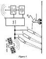
Figure 1 is a general view of the speed regulation system of the present invention;Figure 2 shows a roadway division into risk levels according to the principle of the present invention;Figure 3 is a high level functional block diagrams of the car speed regulation computing system;Figure 4 is a flow chart of the main steps of the method to operate the system of the present invention.- In the following description, numerous specific details are set forth to provide a thorough understanding of the present invention. However, it will be obvious to those skilled in the art that the present invention may be practised without such specific details. In other instances, well-known circuits may be shown in block diagram form in order not to obscure the present invention in unnecessary detail. For the most part, details concerning timing, data formats within communication protocols, and the like have been omitted in as much as such details are not necessary to obtain a complete understanding of the present invention and are within the skills of persons of ordinary skill in the relevant art.
- The invention is implemented as an interactive traffic regulation system in a highway structure and uses existing installations.
- Refer now to the drawings wherein depicted elements are not necessarily shown to scale and wherein like or similar elements are designated by the same reference numeral through the several views. The terms automobile, car, or vehicle may be used interchangeable to generally refer to a vehicle that travels on a highway. A communication protocol refers to all the characteristics necessary to communicate using the protocol, including power levels, frequencies, data formats, etc.
- As shown on
Figure 1 avehicle 100 is equipped with a Global Positioning System (GPS) receiver. The Global Positioning System, developed for the U.S. Department of Defense, allows anyone with a GPS receiver to identify his or her location on the earth's surface with a high degree of accuracy. The GPS receiver receives signals from a number of GPS satellites (only one is shown 102) in non-geosynchronous orbit around the earth. A minimum of three satellites' signals must be received for the GPS receiver to determine a geographical location. Fortunately, sufficient GPS satellites orbit the earth such that at any given time at any given location on the earth's surface, there are more than the requisite number of satellites within reception range. - From reading the signals of the GPS satellites, the GPS receiver determines the geographical location of the vehicle. This location is then used as a search key to retrieve a numerical speed limit from a database. In a first embodiment, the database may be located within the
vehicle 100 and stored in a memory or on a storage device such as a CD-ROM, which may be periodically updated by the vehicle's operator or owner to match with the real-time road conditions modifications. Alternatively, as shown on the figure, thedatabase 104 may be stored in a remote location, in which case the vehicle requests speed limit information from the remote location by transmitting a request through anantenna 106 mounted to the vehicle. Theremote location 104 receives the request through its own antenna (not shown) and responds with the proper speed limit information. - In yet another embodiment, the database may be located in the
vehicle 100, but periodically updated by aremote location 104 transmitting an update signal through a broadcast antenna. The vehicle receives the update signal through its antenna and updates its database based on the update signal. - In any of the above embodiments and furthers alternatives to implement the principle of the present invention, the information provided may concern speed limit information but also road conditions information. As utilised within the invention, the term "road conditions" refers to many different types of conditions including, but not limited to, time of day, upcoming construction areas, upcoming traffic flow, weather conditions, road grades, distance to emergency exit ramps, road weight limits, shoulder widths and distances, and any other information which would be useful to a driver in order to more safely operate a vehicle.
- The information received from the database is provided to a processor (not shown) within the vehicle. The processor receives the information and decodes it before instructing the driver with a resulting useful information for the roadway on which the vehicle is travelling. The information may be either presented to the user on a visual display, or as a voice audio, or as a combination of both.
- Returning to
Figure 1 , series of cameras (108, 110, 112) are mounted along a roadway to catch images of the traffic flow. The traffic flow information is received by acentralised traffic database 104 and analysed to deliver accurate traffic regulations orders 114 on displays posted all along the roadway. - The vehicle is further equipped with a
RFID receiver 116 that allows to receive traffic information from thecentralised traffic database 104. The traffic information is then used and combined with the GPS information within a car processing system to deliver personalised information to the driver and generate specific actions as will be detailed below with reference tofigure 4 . - Also shown on
figure 1 , is acommunication interface block 118 compatible with the RFID communication protocols as well as with the WIFI, the GPS and DGPS communication protocols. The interface block allows the sending in real-time of the traffic information to the car to be processed by the car monitoring system for alerting the driver and/or regulating the car engine. - Going now to
figure 2 , avirtual road division 200 into risk levels zones is now described. One may imagine a car driver being on its way to a urbanism zone. The road may comprise one or several lanes (201-1 to 201-n) and the vehicle is moving on one of them. The road is divided into at least four zones: - a Warning zone (WZ) 202, a Critical zone (CZ) 204, a High Risk zone (HRZ) 206 and a Roadway zone (RZ) 208. Before reaching the High Risk zone, a vehicle crosses a Warning zone and then a Critical zone. The vehicle enters the speed controled
road section 200 coming from a previous Roadway zone and exits the speed controled road section leaving the High Risk zone to enter a new Roadway zone. It is to be understood that the limit of the speed controled section is beyond the frontier between the HRZ and a new RZ section. As illustrated the new roadway zone may include one or more lanes(208-1 to 208-m, m being equal or different to 'n') while a new speed controled road section may include a different number of lanes (210-1 to 210-p, p being equal or different to 'm'). Each zone represents a specific road section for which a respective risk level is associated according to its proximity to the nearest posted speed limit which is within the high risk zone. For each zone, a threshold speed value is associated to allow compliance of the current vehicle speed to the upcoming posted speed limit. Moreover, each threshold value may be dynamically adjusted depending on real-time events such as a traffic and road conditions. - It is to be appreciated that the threshold value associated to the High Risk zone is the posted speed limit, whereas the speed limits associated to the Warning zone and to the Critical zone are speed limits specifically defined to audit the driver behaviour in each zone before entering the High risk zone. The boundaries of each zone are defined by the watching area of each camera (108, 110, 112) posted along the roadway.
- As shown on
figure 2 , the warning zone and the critical zone are divided into sub-areas (202-1 to 202-n; 204-1 to 204-n) that fit each to one in-lane width. It is to be understood that with the real-time monitoring system of the present invention, all the specific control parameters computed for a vehicle that is travelling from one lane to another, either within a same risk zone or not, are updated in real-time to be fully compliant with the new sub-area the vehicle is in. - The
Warning Zone 202 is the low speed control layer zone. During travel of the WZ, the messages provided to the driver are information as regard to the car speed and the posted speed limit proximity to warn the driver. - The
Critical Zone 204 is the last speed tolerance limit before entering the High Risk Zone. The messages provided to the driver are information as regard to the urgency of adapting the vehicle speed to the upcoming speed limit. Car engine regulation may be forced in order to respect the highway-code requirements. The car position as well as the associated speed together with the expected zone limitation are stored to be provided in case of necessity. - The
High Risk Zone 206 represents the posted speed limit zone. Speed control system and highway code monitoring and driving rules can be associated to this zone in a conventional way. As exemplified infigure 2 , the HRZ may be a urbanism zone where vehicles may travel on one lane. - When leaving the HRZ, the vehicle enters the
Roadway Zone 208 wherein the car processing system is reset and set to the speed limitation allowed for the new road portion. - It is to be appreciated that each zone and sub-areas is configured to reflect the environmental structure in terms of speed limit and safety parameters. Traffic information is provided in real-time from the traffic central database to the car computer using the GPS or RFID or WiFi capabilities. The car computer decodes the information received and set up the appropriate actions as described above. Thus the system anticipates the driver attitude by analysing the way the vehicle is moving all along the road.
- Furthermore the system allows to track the driver behaviour by storing the violations into a log file to be reported to the central using the in-car wireless facilities. The in-car memory (not shown here) restores the content of the log file and the worst case violations of the driver attitude are transmitted to the traffic central for control.
Figure 3 depicts in a high level, the functional blocks of the car speedregulation computing system 300 of the present invention. The apparatus is incorporated withinvehicle 100 and provides a self regulated mechanism based on a combination of environmental data and vehicle data. A Traffic Monitoring Intelligent System (TMIS) 301 is coupled to adata acquisition block 305 and receives via the wireless facilities information related to the road conditions from the traffic central. This information is used to give recommendations to the car driver as to the required driving attitude in the current road context. These directives have to be treated in real-time. The TMIS decodes these information to be applied to the environmental data acquisition system of the car computer. The data acquisition block also receives the position inputs from the GPS (or DGPS)receiver 302.- Finally, the data acquisition block receives information issued from an Environmental Data Collection (EDC)
block 303. The EDC catches from the central the data related to the predefined risk zones. Additionally, the EDC may receive punctually data provided by the RFID facilities instead of the wireless ones. - Then, the
data acquisition block 305 senses the incoming data flow from the three upstream sources to provide a rotative arbitration to be transmitted to a 'compare and compute'block 306. The data acquisition block decodes the qualifiers included in the data flow to be further sampled and held by processingblock 306. - Additionally,
car speed sensors 304 allow to detect the current speed of the vehicle in a conventional way not further described here. - Thus, the present system allows to combine in a 'compare and compute'
processing block 306 the information of the car position (from 302), the driving environmental rules (from 301 and 303), the car current speed (from 304) to determine the appropriate actions and notifications to be set according to the risk zone in which the vehicle is travelling. - An
alarm notification block 307 is coupled to the output of the compareblock 306 to generate an in-car alarm when set by an appropriate signal issued from the compare block. - An
action notification block 307 is coupled to the output of the compareblock 306 to generate an in-car driver message when set by an appropriate signal issued from the compare block. - A
speed regulation block 309 is coupled to the output of the compareblock 306 to generate a car engine regulation order to adapt the speed of the vehicle to the appropriate risk zone taking into account the real-time environmental conditions. It is to be appreciated that the engine regulation becomes effective only if the driver has activated an option of automatic speed regulation. Then, the speed regulation order allows anengine speed regulator 310 to adjust to the previously determined speed the current car speed. - Optionally, a Tracking/Car log message may be sent to the traffic central for traceability of the driver attitude. The tracking message contains in a log file the violations of the driver that is reported to the central for use in case of paramount necessity.
- Going to
figure 4 , a flow chart representation of the process of determining which message(s) and/or action(s) is/are to be generated is now described. The process starts atblock 402 to sample at predefined intervals the data provided by theData Acquisition block 305.Block 402 is preferably a 'sample and hold' circuit to hold the incoming data in a memory to be further used during a comparison phase.Block 402 delivers to block 403 the reference values of the risk zones (namely the RZ,WZ,CZ and HRZ ones) that represent the threshold speeds.Block 402 further delivers to block 405 the remaining data sampled not related to vehicle speed.Block 405 allows to store the data received fromblock 402 to be further used as reference of road and traffic conditions. - As previously mentioned, the vehicle speed is determined by the
car speed sensors 304 and is provided tocomparator blocks block 403. It is important to note that the threshold value for each risk zone may be dynamically updated depending on the information received from the central traffic information and the traffic road circumstances. - A series of comparisons begins when the vehicle enters the first risk zone to determine whether the current speed of the vehicle is below the threshold value that corresponds to the risk zone the vehicle is travelling. If a speed limit is exceeded for a particular risk zone (branch Yes of any of the
comparators 406 to 409) the process goes to block 410. Block 410 is a Functional State Machine (FSM) which determines the appropriate directives to be delivered to block 413, based on the events and the condition coming fromblock 405 andcomparator blocks 406 to 409.- For sake of clarity, block 413 is represented as one functional block grouping blocks 307, 308 and 309. According to the result of the FSM computation, the output of
block 413 led to an alarm, a driver recommendation and/or an engine regulation. - Block 410 also feeds
block 411 with tracking log files of the car events in regard to both the traffic directives and the driver attitude that are transmitted to the central using the wireless facilities as already mentioned. The Tracking/Car log message gives the traffic central the traceability of the driver attitude by pushing the different violations into a log file to be reported in case of paramount necessity. - Those skilled in the art will appreciate that the method and system of the present invention has been described for a preferred embodiment, but modifications and variations may be made to the above without departing from the scope of the invention.
Claims (11)
- A method for determining a vehicle speed compliance to an upcoming posted speed limit comprising the steps of:acquiring the current speed and the geographical position of the vehicle;characterized byassigning a risk level to the vehicle, wherein the risklevel corresponds to one of a plurality of risk zones, wherein each zone represents a road section to which a respective risk level is associated according to its distance to the upcoming posted speed limit;determining a threshold speed value based on road and traffic conditions in each of the risk zones and associated to allow compliance of the current vehicle speed to the upcoming posted speed limit;comparing the current speed of the vehicle to the threshold speed value; andgenerating an appropriate set of in-car actions according to the result of the comparing step.
- The method of claim 1, wherein the step of acquiring the current speed of the vehicle comprises the step of receiving such information from in-car sensors.
- The method of claim 1 or 2 wherein the step of acquiring the geographical position of the vehicle comprises the step of receiving such information from a Global Positioning System.
- The method of any one of claims 1 to 3, wherein the step of assigning a risk level comprises the step of accessing a first database of posted speed limits and comparing the vehicle position to the nearest posted speed limit.
- The method of claim 4 wherein the first database is one of an in-car or a remote centralised database.
- The method of any one of claims 1 to 5 wherein the linking step comprises the step of accessing a second database and acquiring a threshold speed value.
- The method of claim 6 wherein the second database is one of an in-car or a remote centralised database.
- The method of claim 7 wherein the second remote database is accessed through a Wireless protocol communication.
- The method of any one of claims 1 to 8 wherein the appropriate set of in-car actions comprise at least one of a driver recommendation message, an audible or visible alert, and an engine regulation.
- A system for determining a vehicle speed compliance to an upcoming posted speed limit comprising means for performing the steps of the method of any one of claims 1 to 9.
- A computer program product stored on a medium readable by a computer machine, the computer program product tangibly embodying readable program means for causing the computer machine to perform the method according to any one of claims 1 to 9.
Priority Applications (1)
| Application Number | Priority Date | Filing Date | Title |
|---|---|---|---|
| EP06793595AEP1960983B1 (en) | 2005-12-15 | 2006-09-18 | Method, system and program for auditing vehicle speed compliance to an upcoming speed limit |
Applications Claiming Priority (3)
| Application Number | Priority Date | Filing Date | Title |
|---|---|---|---|
| EP05301058 | 2005-12-15 | ||
| PCT/EP2006/066455WO2007068512A1 (en) | 2005-12-15 | 2006-09-18 | Method, system and program for auditing vehicle speed compliance to an upcoming speed limit |
| EP06793595AEP1960983B1 (en) | 2005-12-15 | 2006-09-18 | Method, system and program for auditing vehicle speed compliance to an upcoming speed limit |
Publications (2)
| Publication Number | Publication Date |
|---|---|
| EP1960983A1 EP1960983A1 (en) | 2008-08-27 |
| EP1960983B1true EP1960983B1 (en) | 2012-08-29 |
Family
ID=37526953
Family Applications (1)
| Application Number | Title | Priority Date | Filing Date |
|---|---|---|---|
| EP06793595AActiveEP1960983B1 (en) | 2005-12-15 | 2006-09-18 | Method, system and program for auditing vehicle speed compliance to an upcoming speed limit |
Country Status (4)
| Country | Link |
|---|---|
| US (1) | US8626418B2 (en) |
| EP (1) | EP1960983B1 (en) |
| CN (1) | CN101326555B (en) |
| WO (1) | WO2007068512A1 (en) |
Cited By (1)
| Publication number | Priority date | Publication date | Assignee | Title |
|---|---|---|---|---|
| CN105513393A (en)* | 2014-09-24 | 2016-04-20 | 小米科技有限责任公司 | Driving information processing method, device and terminal |
Families Citing this family (43)
| Publication number | Priority date | Publication date | Assignee | Title |
|---|---|---|---|---|
| GB0806166D0 (en)* | 2008-03-25 | 2008-05-14 | Fadahunsi Arc S | Sat nav speed check system |
| TWI338640B (en)* | 2008-10-28 | 2011-03-11 | Wistron Corp | Image recording systems and related recording methods for recording moving image of the vehicle, and machine readable medium thereof |
| CN101840633B (en)* | 2009-03-19 | 2013-04-03 | 创研光电股份有限公司 | Lane Departure Warning with Linked GPS |
| US9688286B2 (en)* | 2009-09-29 | 2017-06-27 | Omnitracs, Llc | System and method for integrating smartphone technology into a safety management platform to improve driver safety |
| GB2474660A (en)* | 2009-10-21 | 2011-04-27 | Rory O'gorman | Speed and location monitoring apparatus and method for vehicles |
| JP2011129106A (en)* | 2009-11-19 | 2011-06-30 | Sanyo Electric Co Ltd | Radio apparatus |
| US8598977B2 (en)* | 2010-04-16 | 2013-12-03 | Tiny Towne International Llc | System and method for driver training in a controlled driving environment |
| US9035796B2 (en)* | 2011-11-07 | 2015-05-19 | Ford Global Technologies | Reduce speed ahead information delivery |
| CN102542812B (en)* | 2012-01-14 | 2013-08-14 | 长安大学 | PDA (Personal Digital Assistant)-based overall speed detecting and data processing method |
| US9042872B1 (en) | 2012-04-26 | 2015-05-26 | Intelligent Technologies International, Inc. | In-vehicle driver cell phone detector |
| US9489839B2 (en) | 2012-08-06 | 2016-11-08 | Cloudparc, Inc. | Tracking a vehicle using an unmanned aerial vehicle |
| US8836788B2 (en) | 2012-08-06 | 2014-09-16 | Cloudparc, Inc. | Controlling use of parking spaces and restricted locations using multiple cameras |
| US9171382B2 (en)* | 2012-08-06 | 2015-10-27 | Cloudparc, Inc. | Tracking speeding violations and controlling use of parking spaces using cameras |
| CN103198687B (en)* | 2013-03-29 | 2016-04-06 | 毕晓光 | Restricted driving reminding method and system |
| US20210133871A1 (en) | 2014-05-20 | 2021-05-06 | State Farm Mutual Automobile Insurance Company | Autonomous vehicle operation feature usage recommendations |
| US11669090B2 (en) | 2014-05-20 | 2023-06-06 | State Farm Mutual Automobile Insurance Company | Autonomous vehicle operation feature monitoring and evaluation of effectiveness |
| US10599155B1 (en) | 2014-05-20 | 2020-03-24 | State Farm Mutual Automobile Insurance Company | Autonomous vehicle operation feature monitoring and evaluation of effectiveness |
| US9972054B1 (en) | 2014-05-20 | 2018-05-15 | State Farm Mutual Automobile Insurance Company | Accident fault determination for autonomous vehicles |
| US10373259B1 (en) | 2014-05-20 | 2019-08-06 | State Farm Mutual Automobile Insurance Company | Fully autonomous vehicle insurance pricing |
| CN104036638B (en)* | 2014-06-10 | 2016-06-15 | 深圳市元征科技股份有限公司 | A kind of real-time road monitoring method and real-time road monitoring device |
| US10387962B1 (en) | 2014-07-21 | 2019-08-20 | State Farm Mutual Automobile Insurance Company | Methods of reconstructing an accident scene using telematics data |
| CN105528898B (en)* | 2014-09-28 | 2018-03-23 | 深圳市赛格导航科技股份有限公司 | A kind of speed monitoring method and speed monitoring system based on vehicle position information |
| US10157423B1 (en) | 2014-11-13 | 2018-12-18 | State Farm Mutual Automobile Insurance Company | Autonomous vehicle operating style and mode monitoring |
| CN104599524B (en)* | 2015-02-06 | 2017-12-08 | 深圳市易流科技股份有限公司 | A kind of method for judging vehicle-state and the vehicle monitoring system using this method |
| US20160283874A1 (en)* | 2015-03-23 | 2016-09-29 | International Business Machines Corporation | Failure modeling by incorporation of terrestrial conditions |
| US9479903B2 (en)* | 2015-05-23 | 2016-10-25 | Suliman ALBASHEIR | Methods and systems for monitoring moving UE/vehicle speed in wireless networks |
| US9805601B1 (en) | 2015-08-28 | 2017-10-31 | State Farm Mutual Automobile Insurance Company | Vehicular traffic alerts for avoidance of abnormal traffic conditions |
| US9595191B1 (en)* | 2015-11-12 | 2017-03-14 | Lytx, Inc. | Traffic estimation |
| DE102015224131A1 (en)* | 2015-12-03 | 2017-06-08 | Jenoptik Robot Gmbh | Method and device for speed monitoring in a traffic area, traffic monitoring device (VÜG) and traffic monitoring system with conditional trigger threshold value |
| MX388583B (en) | 2015-12-28 | 2025-03-19 | Imperio Llc | SYSTEM FOR CONTROLLING THE SPEED OF A VEHICLE. |
| US10324463B1 (en)* | 2016-01-22 | 2019-06-18 | State Farm Mutual Automobile Insurance Company | Autonomous vehicle operation adjustment based upon route |
| US10134278B1 (en) | 2016-01-22 | 2018-11-20 | State Farm Mutual Automobile Insurance Company | Autonomous vehicle application |
| US11719545B2 (en) | 2016-01-22 | 2023-08-08 | Hyundai Motor Company | Autonomous vehicle component damage and salvage assessment |
| US11242051B1 (en) | 2016-01-22 | 2022-02-08 | State Farm Mutual Automobile Insurance Company | Autonomous vehicle action communications |
| US10493936B1 (en) | 2016-01-22 | 2019-12-03 | State Farm Mutual Automobile Insurance Company | Detecting and responding to autonomous vehicle collisions |
| US11441916B1 (en) | 2016-01-22 | 2022-09-13 | State Farm Mutual Automobile Insurance Company | Autonomous vehicle trip routing |
| US9937923B2 (en) | 2016-01-30 | 2018-04-10 | Bendix Commercial Vehicle Systems Llc | System and method for providing a speed warning and speed control |
| EP3354534B1 (en)* | 2017-01-25 | 2021-03-31 | Volvo Car Corporation | Method and system for sharing of information pertinent a railway crossing |
| CN114572275A (en) | 2020-12-02 | 2022-06-03 | 晋城三赢精密电子有限公司 | Vehicle driving assistance method, vehicle-mounted device, vehicle and storage medium |
| TWI751820B (en)* | 2020-12-02 | 2022-01-01 | 新煒科技有限公司 | Driving assistance method, vehicle-mounted device, vehicle, and storage medium |
| CN112950974B (en)* | 2021-04-12 | 2023-01-31 | 东风柳州汽车有限公司 | Vehicle speed limit prompting method, device, equipment and storage medium |
| US11217044B1 (en)* | 2021-05-11 | 2022-01-04 | Samsara Inc. | Map-based notification system |
| CN115416484A (en)* | 2022-08-30 | 2022-12-02 | 潍柴动力股份有限公司 | Method, device and system for regionalized control of vehicle operating status |
Family Cites Families (19)
| Publication number | Priority date | Publication date | Assignee | Title |
|---|---|---|---|---|
| US5485161A (en) | 1994-11-21 | 1996-01-16 | Trimble Navigation Limited | Vehicle speed control based on GPS/MAP matching of posted speeds |
| JP2000046574A (en)* | 1998-07-24 | 2000-02-18 | Honda Motor Co Ltd | Vehicle navigation system |
| US6212465B1 (en)* | 1999-12-22 | 2001-04-03 | Visteon Global Technologies Inc. | Method and system for controlling vehicle speed based on vehicle yaw rate and yaw acceleration |
| US7382274B1 (en)* | 2000-01-21 | 2008-06-03 | Agere Systems Inc. | Vehicle interaction communication system |
| DE10018557A1 (en)* | 2000-04-14 | 2001-10-18 | Bosch Gmbh Robert | Regulating vehicle speed involves applying acceleration or acceleration change limit if in addition to/instead of transverse acceleration, preceding vehicle reaches radar sensing range limit |
| JP4211214B2 (en)* | 2000-10-13 | 2009-01-21 | 富士電機デバイステクノロジー株式会社 | Magnetic transfer apparatus and method using perpendicular magnetic medium |
| US6462675B1 (en) | 2000-10-13 | 2002-10-08 | International Business Machines Corporation | Method, system, and program for auditing driver compliance to a current speed limit |
| JP3909647B2 (en)* | 2000-12-13 | 2007-04-25 | 本田技研工業株式会社 | Auto cruise equipment |
| US6515596B2 (en) | 2001-03-08 | 2003-02-04 | International Business Machines Corporation | Speed limit display in a vehicle |
| CN2468812Y (en)* | 2001-03-28 | 2002-01-02 | 王军 | Arrangement for limiting over-loading or over-speed for vehicle |
| DE10218017A1 (en)* | 2002-04-23 | 2003-11-06 | Bosch Gmbh Robert | Method for speed and distance control in motor vehicles |
| JP3832380B2 (en)* | 2002-04-25 | 2006-10-11 | 株式会社日立製作所 | Automatic vehicle speed control device |
| US6825778B2 (en) | 2002-10-21 | 2004-11-30 | International Road Dynamics Inc. | Variable speed limit system |
| US6970102B2 (en)* | 2003-05-05 | 2005-11-29 | Transol Pty Ltd | Traffic violation detection, recording and evidence processing system |
| KR20050068938A (en)* | 2003-12-30 | 2005-07-05 | 현대자동차주식회사 | Method of a traffic conditions decision |
| JP2005271822A (en)* | 2004-03-25 | 2005-10-06 | Mitsubishi Fuso Truck & Bus Corp | Vehicular automatic deceleration control device |
| US20070010941A1 (en)* | 2005-07-07 | 2007-01-11 | Marsh David C | Land navigation system |
| US7739036B2 (en)* | 2005-08-26 | 2010-06-15 | Gm Global Technology Operations, Inc. | Speed limit advisor |
| US8188887B2 (en)* | 2009-02-13 | 2012-05-29 | Inthinc Technology Solutions, Inc. | System and method for alerting drivers to road conditions |
- 2006
- 2006-09-18EPEP06793595Apatent/EP1960983B1/enactiveActive
- 2006-09-18USUS12/095,532patent/US8626418B2/enactiveActive
- 2006-09-18WOPCT/EP2006/066455patent/WO2007068512A1/enactiveApplication Filing
- 2006-09-18CNCN2006800465197Apatent/CN101326555B/enactiveActive
Cited By (1)
| Publication number | Priority date | Publication date | Assignee | Title |
|---|---|---|---|---|
| CN105513393A (en)* | 2014-09-24 | 2016-04-20 | 小米科技有限责任公司 | Driving information processing method, device and terminal |
Also Published As
| Publication number | Publication date |
|---|---|
| US8626418B2 (en) | 2014-01-07 |
| CN101326555A (en) | 2008-12-17 |
| CN101326555B (en) | 2010-12-08 |
| US20110010042A1 (en) | 2011-01-13 |
| EP1960983A1 (en) | 2008-08-27 |
| WO2007068512A1 (en) | 2007-06-21 |
Similar Documents
| Publication | Publication Date | Title |
|---|---|---|
| EP1960983B1 (en) | Method, system and program for auditing vehicle speed compliance to an upcoming speed limit | |
| US11807231B2 (en) | Electronic device for vehicle and operating method thereof | |
| US8248223B2 (en) | Speed reporting for providing conditional driver treatment | |
| CN111524346B (en) | Server and information providing device | |
| US9903733B2 (en) | Vehicular communications network and methods of use and manufacture thereof | |
| US8188887B2 (en) | System and method for alerting drivers to road conditions | |
| US6868331B2 (en) | Method for outputting traffic information in a motor vehicle | |
| JP6439735B2 (en) | Driving support device | |
| EP3545508B1 (en) | Method and device for selecting notification recipient | |
| JP2010066827A (en) | Driving support system, driving support device and driving support method | |
| JP2001331893A (en) | Traffic violation warning and traffic violation storage device | |
| JP2023067970A (en) | Information processor | |
| WO2017035493A1 (en) | Monitoring and reporting slow drivers in fast highway lanes | |
| US20230392948A1 (en) | Vehicle communication and navigation systems for road safety | |
| US20230117426A1 (en) | Method and system for adaptively providing auxiliary driving information | |
| JP3602977B2 (en) | Network-type signage system and recording medium that records programs for in-vehicle information devices | |
| JP2023145745A (en) | Information generation device, information generation method, and information generation device program | |
| CN109711737A (en) | A kind of threat vehicle checking method, apparatus and system | |
| JP2007293687A (en) | Driving support device | |
| JP7239815B2 (en) | Traffic congestion prevention server, traffic congestion prevention device, traffic congestion prevention system, traffic congestion prevention method, and program | |
| JP2018139031A (en) | Information provision device, information provision method, and computer program | |
| JP5720951B2 (en) | Traffic information distribution system, traffic information system, traffic information distribution program, and traffic information distribution method | |
| KR102385191B1 (en) | Real-time dangerous vehicle tracking system and tracking method | |
| KR20120039979A (en) | Apparatus for providing road information using wireless signal | |
| Panou et al. | ITS clustering and terminology: one concept with many meanings |
Legal Events
| Date | Code | Title | Description |
|---|---|---|---|
| PUAI | Public reference made under article 153(3) epc to a published international application that has entered the european phase | Free format text:ORIGINAL CODE: 0009012 | |
| 17P | Request for examination filed | Effective date:20080425 | |
| AK | Designated contracting states | Kind code of ref document:A1 Designated state(s):AT BE BG CH CY CZ DE DK EE ES FI FR GB GR HU IE IS IT LI LT LU LV MC NL PL PT RO SE SI SK TR | |
| 17Q | First examination report despatched | Effective date:20110309 | |
| GRAP | Despatch of communication of intention to grant a patent | Free format text:ORIGINAL CODE: EPIDOSNIGR1 | |
| DAX | Request for extension of the european patent (deleted) | ||
| GRAS | Grant fee paid | Free format text:ORIGINAL CODE: EPIDOSNIGR3 | |
| GRAA | (expected) grant | Free format text:ORIGINAL CODE: 0009210 | |
| AK | Designated contracting states | Kind code of ref document:B1 Designated state(s):AT BE BG CH CY CZ DE DK EE ES FI FR GB GR HU IE IS IT LI LT LU LV MC NL PL PT RO SE SI SK TR | |
| REG | Reference to a national code | Ref country code:GB Ref legal event code:FG4D | |
| REG | Reference to a national code | Ref country code:CH Ref legal event code:NV Representative=s name:IBM RESEARCH GMBH ZURICH RESEARCH LABORATORY INTEL Ref country code:CH Ref legal event code:EP | |
| REG | Reference to a national code | Ref country code:AT Ref legal event code:REF Ref document number:573418 Country of ref document:AT Kind code of ref document:T Effective date:20120915 | |
| REG | Reference to a national code | Ref country code:DE Ref legal event code:R084 Ref document number:602006031758 Country of ref document:DE | |
| REG | Reference to a national code | Ref country code:DE Ref legal event code:R082 Ref document number:602006031758 Country of ref document:DE Representative=s name:DUSCHER, REINHARD, DIPL.-PHYS. DR.RER.NAT., DE Ref country code:DE Ref legal event code:R082 Ref document number:602006031758 Country of ref document:DE Representative=s name:REINHARD DUSCHER, DE Ref country code:IE Ref legal event code:FG4D | |
| REG | Reference to a national code | Ref country code:DE Ref legal event code:R096 Ref document number:602006031758 Country of ref document:DE Effective date:20121025 | |
| REG | Reference to a national code | Ref country code:DE Ref legal event code:R084 Ref document number:602006031758 Country of ref document:DE Effective date:20120921 | |
| REG | Reference to a national code | Ref country code:GB Ref legal event code:746 Effective date:20121029 | |
| REG | Reference to a national code | Ref country code:AT Ref legal event code:MK05 Ref document number:573418 Country of ref document:AT Kind code of ref document:T Effective date:20120829 | |
| REG | Reference to a national code | Ref country code:NL Ref legal event code:VDEP Effective date:20120829 | |
| REG | Reference to a national code | Ref country code:LT Ref legal event code:MG4D Effective date:20120829 | |
| PG25 | Lapsed in a contracting state [announced via postgrant information from national office to epo] | Ref country code:IS Free format text:LAPSE BECAUSE OF FAILURE TO SUBMIT A TRANSLATION OF THE DESCRIPTION OR TO PAY THE FEE WITHIN THE PRESCRIBED TIME-LIMIT Effective date:20121229 Ref country code:FI Free format text:LAPSE BECAUSE OF FAILURE TO SUBMIT A TRANSLATION OF THE DESCRIPTION OR TO PAY THE FEE WITHIN THE PRESCRIBED TIME-LIMIT Effective date:20120829 Ref country code:LT Free format text:LAPSE BECAUSE OF FAILURE TO SUBMIT A TRANSLATION OF THE DESCRIPTION OR TO PAY THE FEE WITHIN THE PRESCRIBED TIME-LIMIT Effective date:20120829 Ref country code:CY Free format text:LAPSE BECAUSE OF FAILURE TO SUBMIT A TRANSLATION OF THE DESCRIPTION OR TO PAY THE FEE WITHIN THE PRESCRIBED TIME-LIMIT Effective date:20120829 Ref country code:AT Free format text:LAPSE BECAUSE OF FAILURE TO SUBMIT A TRANSLATION OF THE DESCRIPTION OR TO PAY THE FEE WITHIN THE PRESCRIBED TIME-LIMIT Effective date:20120829 | |
| PG25 | Lapsed in a contracting state [announced via postgrant information from national office to epo] | Ref country code:BE Free format text:LAPSE BECAUSE OF FAILURE TO SUBMIT A TRANSLATION OF THE DESCRIPTION OR TO PAY THE FEE WITHIN THE PRESCRIBED TIME-LIMIT Effective date:20120829 Ref country code:SE Free format text:LAPSE BECAUSE OF FAILURE TO SUBMIT A TRANSLATION OF THE DESCRIPTION OR TO PAY THE FEE WITHIN THE PRESCRIBED TIME-LIMIT Effective date:20120829 Ref country code:LV Free format text:LAPSE BECAUSE OF FAILURE TO SUBMIT A TRANSLATION OF THE DESCRIPTION OR TO PAY THE FEE WITHIN THE PRESCRIBED TIME-LIMIT Effective date:20120829 Ref country code:SI Free format text:LAPSE BECAUSE OF FAILURE TO SUBMIT A TRANSLATION OF THE DESCRIPTION OR TO PAY THE FEE WITHIN THE PRESCRIBED TIME-LIMIT Effective date:20120829 Ref country code:PT Free format text:LAPSE BECAUSE OF FAILURE TO SUBMIT A TRANSLATION OF THE DESCRIPTION OR TO PAY THE FEE WITHIN THE PRESCRIBED TIME-LIMIT Effective date:20121231 | |
| PG25 | Lapsed in a contracting state [announced via postgrant information from national office to epo] | Ref country code:RO Free format text:LAPSE BECAUSE OF FAILURE TO SUBMIT A TRANSLATION OF THE DESCRIPTION OR TO PAY THE FEE WITHIN THE PRESCRIBED TIME-LIMIT Effective date:20120829 Ref country code:EE Free format text:LAPSE BECAUSE OF FAILURE TO SUBMIT A TRANSLATION OF THE DESCRIPTION OR TO PAY THE FEE WITHIN THE PRESCRIBED TIME-LIMIT Effective date:20120829 Ref country code:MC Free format text:LAPSE BECAUSE OF NON-PAYMENT OF DUE FEES Effective date:20120930 Ref country code:NL Free format text:LAPSE BECAUSE OF FAILURE TO SUBMIT A TRANSLATION OF THE DESCRIPTION OR TO PAY THE FEE WITHIN THE PRESCRIBED TIME-LIMIT Effective date:20120829 Ref country code:CZ Free format text:LAPSE BECAUSE OF FAILURE TO SUBMIT A TRANSLATION OF THE DESCRIPTION OR TO PAY THE FEE WITHIN THE PRESCRIBED TIME-LIMIT Effective date:20120829 Ref country code:DK Free format text:LAPSE BECAUSE OF FAILURE TO SUBMIT A TRANSLATION OF THE DESCRIPTION OR TO PAY THE FEE WITHIN THE PRESCRIBED TIME-LIMIT Effective date:20120829 Ref country code:ES Free format text:LAPSE BECAUSE OF FAILURE TO SUBMIT A TRANSLATION OF THE DESCRIPTION OR TO PAY THE FEE WITHIN THE PRESCRIBED TIME-LIMIT Effective date:20121210 | |
| REG | Reference to a national code | Ref country code:CH Ref legal event code:PL | |
| PG25 | Lapsed in a contracting state [announced via postgrant information from national office to epo] | Ref country code:PL Free format text:LAPSE BECAUSE OF FAILURE TO SUBMIT A TRANSLATION OF THE DESCRIPTION OR TO PAY THE FEE WITHIN THE PRESCRIBED TIME-LIMIT Effective date:20120829 Ref country code:SK Free format text:LAPSE BECAUSE OF FAILURE TO SUBMIT A TRANSLATION OF THE DESCRIPTION OR TO PAY THE FEE WITHIN THE PRESCRIBED TIME-LIMIT Effective date:20120829 Ref country code:IT Free format text:LAPSE BECAUSE OF FAILURE TO SUBMIT A TRANSLATION OF THE DESCRIPTION OR TO PAY THE FEE WITHIN THE PRESCRIBED TIME-LIMIT Effective date:20120829 | |
| REG | Reference to a national code | Ref country code:IE Ref legal event code:MM4A | |
| PLBE | No opposition filed within time limit | Free format text:ORIGINAL CODE: 0009261 | |
| STAA | Information on the status of an ep patent application or granted ep patent | Free format text:STATUS: NO OPPOSITION FILED WITHIN TIME LIMIT | |
| PG25 | Lapsed in a contracting state [announced via postgrant information from national office to epo] | Ref country code:BG Free format text:LAPSE BECAUSE OF FAILURE TO SUBMIT A TRANSLATION OF THE DESCRIPTION OR TO PAY THE FEE WITHIN THE PRESCRIBED TIME-LIMIT Effective date:20121129 Ref country code:CH Free format text:LAPSE BECAUSE OF NON-PAYMENT OF DUE FEES Effective date:20120930 Ref country code:LI Free format text:LAPSE BECAUSE OF NON-PAYMENT OF DUE FEES Effective date:20120930 Ref country code:IE Free format text:LAPSE BECAUSE OF NON-PAYMENT OF DUE FEES Effective date:20120918 | |
| REG | Reference to a national code | Ref country code:FR Ref legal event code:ST Effective date:20130628 | |
| 26N | No opposition filed | Effective date:20130530 | |
| PG25 | Lapsed in a contracting state [announced via postgrant information from national office to epo] | Ref country code:FR Free format text:LAPSE BECAUSE OF NON-PAYMENT OF DUE FEES Effective date:20121029 | |
| REG | Reference to a national code | Ref country code:DE Ref legal event code:R097 Ref document number:602006031758 Country of ref document:DE Effective date:20130530 | |
| PG25 | Lapsed in a contracting state [announced via postgrant information from national office to epo] | Ref country code:TR Free format text:LAPSE BECAUSE OF FAILURE TO SUBMIT A TRANSLATION OF THE DESCRIPTION OR TO PAY THE FEE WITHIN THE PRESCRIBED TIME-LIMIT Effective date:20120829 | |
| PG25 | Lapsed in a contracting state [announced via postgrant information from national office to epo] | Ref country code:LU Free format text:LAPSE BECAUSE OF NON-PAYMENT OF DUE FEES Effective date:20120918 | |
| PG25 | Lapsed in a contracting state [announced via postgrant information from national office to epo] | Ref country code:HU Free format text:LAPSE BECAUSE OF FAILURE TO SUBMIT A TRANSLATION OF THE DESCRIPTION OR TO PAY THE FEE WITHIN THE PRESCRIBED TIME-LIMIT Effective date:20060918 | |
| PG25 | Lapsed in a contracting state [announced via postgrant information from national office to epo] | Ref country code:GR Free format text:LAPSE BECAUSE OF FAILURE TO SUBMIT A TRANSLATION OF THE DESCRIPTION OR TO PAY THE FEE WITHIN THE PRESCRIBED TIME-LIMIT Effective date:20120829 | |
| REG | Reference to a national code | Ref country code:DE Ref legal event code:R082 Ref document number:602006031758 Country of ref document:DE Representative=s name:RICHARDT PATENTANWAELTE PARTG MBB, DE Ref country code:DE Ref legal event code:R082 Ref document number:602006031758 Country of ref document:DE Representative=s name:KUISMA, SIRPA, FI | |
| REG | Reference to a national code | Ref country code:DE Ref legal event code:R081 Ref document number:602006031758 Country of ref document:DE Owner name:KYNDRYL, INC., NEW YORK, US Free format text:FORMER OWNER: INTERNATIONAL BUSINESS MACHINES CORPORATION, ARMONK, N.Y., US Ref country code:DE Ref legal event code:R082 Ref document number:602006031758 Country of ref document:DE Representative=s name:RICHARDT PATENTANWAELTE PARTG MBB, DE | |
| REG | Reference to a national code | Ref country code:GB Ref legal event code:732E Free format text:REGISTERED BETWEEN 20220106 AND 20220112 | |
| P01 | Opt-out of the competence of the unified patent court (upc) registered | Effective date:20230524 | |
| PGFP | Annual fee paid to national office [announced via postgrant information from national office to epo] | Ref country code:DE Payment date:20240919 Year of fee payment:19 | |
| PGFP | Annual fee paid to national office [announced via postgrant information from national office to epo] | Ref country code:GB Payment date:20240923 Year of fee payment:19 |