EP1959298A2 - Method for structuring a layer onto a substrate - Google Patents
Method for structuring a layer onto a substrateDownload PDFInfo
- Publication number
- EP1959298A2 EP1959298A2EP08002496AEP08002496AEP1959298A2EP 1959298 A2EP1959298 A2EP 1959298A2EP 08002496 AEP08002496 AEP 08002496AEP 08002496 AEP08002496 AEP 08002496AEP 1959298 A2EP1959298 A2EP 1959298A2
- Authority
- EP
- European Patent Office
- Prior art keywords
- layer
- mask
- radiation
- polymer
- arrangement
- Prior art date
- Legal status (The legal status is an assumption and is not a legal conclusion. Google has not performed a legal analysis and makes no representation as to the accuracy of the status listed.)
- Granted
Links
- 238000000034methodMethods0.000titleclaimsabstractdescription43
- 239000000758substrateSubstances0.000titleclaimsabstractdescription27
- 229920000642polymerPolymers0.000claimsabstractdescription84
- 230000005855radiationEffects0.000claimsabstractdescription53
- 239000002904solventSubstances0.000claimsabstractdescription22
- 239000000654additiveSubstances0.000claimsabstractdescription9
- 239000007788liquidSubstances0.000claimsdescription10
- 230000001590oxidative effectEffects0.000claimsdescription6
- 230000005670electromagnetic radiationEffects0.000claimsdescription4
- 239000002245particleSubstances0.000claimsdescription3
- 230000000996additive effectEffects0.000abstractdescription3
- 238000011010flushing procedureMethods0.000abstract1
- 239000010410layerSubstances0.000description68
- OKKJLVBELUTLKV-UHFFFAOYSA-NMethanolChemical compoundOCOKKJLVBELUTLKV-UHFFFAOYSA-N0.000description18
- 239000000463materialSubstances0.000description15
- YMWUJEATGCHHMB-UHFFFAOYSA-NDichloromethaneChemical compoundClCClYMWUJEATGCHHMB-UHFFFAOYSA-N0.000description14
- XDTMQSROBMDMFD-UHFFFAOYSA-NCyclohexaneChemical compoundC1CCCCC1XDTMQSROBMDMFD-UHFFFAOYSA-N0.000description13
- HEDRZPFGACZZDS-UHFFFAOYSA-NChloroformChemical compoundClC(Cl)ClHEDRZPFGACZZDS-UHFFFAOYSA-N0.000description12
- WYURNTSHIVDZCO-UHFFFAOYSA-NTetrahydrofuranChemical compoundC1CCOC1WYURNTSHIVDZCO-UHFFFAOYSA-N0.000description12
- YXFVVABEGXRONW-UHFFFAOYSA-NTolueneChemical compoundCC1=CC=CC=C1YXFVVABEGXRONW-UHFFFAOYSA-N0.000description11
- 229920002120photoresistant polymerPolymers0.000description11
- WEVYAHXRMPXWCK-UHFFFAOYSA-NAcetonitrileChemical compoundCC#NWEVYAHXRMPXWCK-UHFFFAOYSA-N0.000description10
- 238000004132cross linkingMethods0.000description10
- 238000004519manufacturing processMethods0.000description10
- 239000002344surface layerSubstances0.000description10
- 239000004793PolystyreneSubstances0.000description8
- 239000000126substanceSubstances0.000description8
- 238000007306functionalization reactionMethods0.000description7
- 239000011521glassSubstances0.000description7
- 238000012986modificationMethods0.000description7
- 229920002223polystyrenePolymers0.000description7
- 230000004048modificationEffects0.000description6
- YLQBMQCUIZJEEH-UHFFFAOYSA-NtetrahydrofuranNatural productsC=1C=COC=1YLQBMQCUIZJEEH-UHFFFAOYSA-N0.000description6
- QVGXLLKOCUKJST-UHFFFAOYSA-Natomic oxygenChemical compound[O]QVGXLLKOCUKJST-UHFFFAOYSA-N0.000description5
- 238000001459lithographyMethods0.000description5
- 239000001301oxygenSubstances0.000description5
- 229910052760oxygenInorganic materials0.000description5
- 238000011161developmentMethods0.000description4
- QSHDDOUJBYECFT-UHFFFAOYSA-NmercuryChemical compound[Hg]QSHDDOUJBYECFT-UHFFFAOYSA-N0.000description4
- XLYOFNOQVPJJNP-UHFFFAOYSA-NwaterChemical compoundOXLYOFNOQVPJJNP-UHFFFAOYSA-N0.000description4
- 238000006243chemical reactionMethods0.000description3
- 229920003229poly(methyl methacrylate)Polymers0.000description3
- 239000004926polymethyl methacrylateSubstances0.000description3
- XKRFYHLGVUSROY-UHFFFAOYSA-NArgonChemical compound[Ar]XKRFYHLGVUSROY-UHFFFAOYSA-N0.000description2
- IJGRMHOSHXDMSA-UHFFFAOYSA-NAtomic nitrogenChemical compoundN#NIJGRMHOSHXDMSA-UHFFFAOYSA-N0.000description2
- RYGMFSIKBFXOCR-UHFFFAOYSA-NCopperChemical compound[Cu]RYGMFSIKBFXOCR-UHFFFAOYSA-N0.000description2
- VYPSYNLAJGMNEJ-UHFFFAOYSA-NSilicium dioxideChemical compoundO=[Si]=OVYPSYNLAJGMNEJ-UHFFFAOYSA-N0.000description2
- XUIMIQQOPSSXEZ-UHFFFAOYSA-NSiliconChemical compound[Si]XUIMIQQOPSSXEZ-UHFFFAOYSA-N0.000description2
- 238000000089atomic force micrographMethods0.000description2
- 230000015572biosynthetic processEffects0.000description2
- 230000021164cell adhesionEffects0.000description2
- 229910052802copperInorganic materials0.000description2
- 239000010949copperSubstances0.000description2
- 238000004090dissolutionMethods0.000description2
- 238000000609electron-beam lithographyMethods0.000description2
- 238000005516engineering processMethods0.000description2
- 239000007789gasSubstances0.000description2
- 230000003647oxidationEffects0.000description2
- 238000007254oxidation reactionMethods0.000description2
- 238000000059patterningMethods0.000description2
- 238000002360preparation methodMethods0.000description2
- 230000001681protective effectEffects0.000description2
- 238000007348radical reactionMethods0.000description2
- 238000004627transmission electron microscopyMethods0.000description2
- 240000003517Elaeocarpus dentatusSpecies0.000description1
- 229910052786argonInorganic materials0.000description1
- 230000015556catabolic processEffects0.000description1
- 229920001940conductive polymerPolymers0.000description1
- 238000000942confocal micrographMethods0.000description1
- 238000007796conventional methodMethods0.000description1
- 239000011162core materialSubstances0.000description1
- 229920006037cross link polymerPolymers0.000description1
- 238000006731degradation reactionMethods0.000description1
- 238000009826distributionMethods0.000description1
- 239000003814drugSubstances0.000description1
- 238000001312dry etchingMethods0.000description1
- 238000004070electrodepositionMethods0.000description1
- 238000010894electron beam technologyMethods0.000description1
- 238000005530etchingMethods0.000description1
- 238000001704evaporationMethods0.000description1
- 230000008020evaporationEffects0.000description1
- 230000007717exclusionEffects0.000description1
- 239000012530fluidSubstances0.000description1
- 230000004927fusionEffects0.000description1
- 230000002209hydrophobic effectEffects0.000description1
- 238000005286illuminationMethods0.000description1
- 229910052751metalInorganic materials0.000description1
- 239000002184metalSubstances0.000description1
- 150000002739metalsChemical class0.000description1
- 229910052757nitrogenInorganic materials0.000description1
- 230000003287optical effectEffects0.000description1
- 239000013307optical fiberSubstances0.000description1
- 210000000056organAnatomy0.000description1
- 239000011368organic materialSubstances0.000description1
- 238000012545processingMethods0.000description1
- 239000012495reaction gasSubstances0.000description1
- 230000001172regenerating effectEffects0.000description1
- 230000010076replicationEffects0.000description1
- 239000004065semiconductorSubstances0.000description1
- 229910052710siliconInorganic materials0.000description1
- 239000010703siliconSubstances0.000description1
- 239000007787solidSubstances0.000description1
- 238000001228spectrumMethods0.000description1
- 238000009987spinningMethods0.000description1
- 238000006557surface reactionMethods0.000description1
- 238000012876topographyMethods0.000description1
- 238000009281ultraviolet germicidal irradiationMethods0.000description1
Images


Classifications
- G—PHYSICS
- G03—PHOTOGRAPHY; CINEMATOGRAPHY; ANALOGOUS TECHNIQUES USING WAVES OTHER THAN OPTICAL WAVES; ELECTROGRAPHY; HOLOGRAPHY
- G03F—PHOTOMECHANICAL PRODUCTION OF TEXTURED OR PATTERNED SURFACES, e.g. FOR PRINTING, FOR PROCESSING OF SEMICONDUCTOR DEVICES; MATERIALS THEREFOR; ORIGINALS THEREFOR; APPARATUS SPECIALLY ADAPTED THEREFOR
- G03F7/00—Photomechanical, e.g. photolithographic, production of textured or patterned surfaces, e.g. printing surfaces; Materials therefor, e.g. comprising photoresists; Apparatus specially adapted therefor
- G03F7/0002—Lithographic processes using patterning methods other than those involving the exposure to radiation, e.g. by stamping
- B—PERFORMING OPERATIONS; TRANSPORTING
- B81—MICROSTRUCTURAL TECHNOLOGY
- B81C—PROCESSES OR APPARATUS SPECIALLY ADAPTED FOR THE MANUFACTURE OR TREATMENT OF MICROSTRUCTURAL DEVICES OR SYSTEMS
- B81C1/00—Manufacture or treatment of devices or systems in or on a substrate
- B81C1/00015—Manufacture or treatment of devices or systems in or on a substrate for manufacturing microsystems
- B81C1/00023—Manufacture or treatment of devices or systems in or on a substrate for manufacturing microsystems without movable or flexible elements
- B81C1/00055—Grooves
- B81C1/00071—Channels
- B—PERFORMING OPERATIONS; TRANSPORTING
- B82—NANOTECHNOLOGY
- B82Y—SPECIFIC USES OR APPLICATIONS OF NANOSTRUCTURES; MEASUREMENT OR ANALYSIS OF NANOSTRUCTURES; MANUFACTURE OR TREATMENT OF NANOSTRUCTURES
- B82Y10/00—Nanotechnology for information processing, storage or transmission, e.g. quantum computing or single electron logic
- B—PERFORMING OPERATIONS; TRANSPORTING
- B82—NANOTECHNOLOGY
- B82Y—SPECIFIC USES OR APPLICATIONS OF NANOSTRUCTURES; MEASUREMENT OR ANALYSIS OF NANOSTRUCTURES; MANUFACTURE OR TREATMENT OF NANOSTRUCTURES
- B82Y40/00—Manufacture or treatment of nanostructures
- G—PHYSICS
- G03—PHOTOGRAPHY; CINEMATOGRAPHY; ANALOGOUS TECHNIQUES USING WAVES OTHER THAN OPTICAL WAVES; ELECTROGRAPHY; HOLOGRAPHY
- G03F—PHOTOMECHANICAL PRODUCTION OF TEXTURED OR PATTERNED SURFACES, e.g. FOR PRINTING, FOR PROCESSING OF SEMICONDUCTOR DEVICES; MATERIALS THEREFOR; ORIGINALS THEREFOR; APPARATUS SPECIALLY ADAPTED THEREFOR
- G03F7/00—Photomechanical, e.g. photolithographic, production of textured or patterned surfaces, e.g. printing surfaces; Materials therefor, e.g. comprising photoresists; Apparatus specially adapted therefor
- G03F7/20—Exposure; Apparatus therefor
- G03F7/2002—Exposure; Apparatus therefor with visible light or UV light, through an original having an opaque pattern on a transparent support, e.g. film printing, projection printing; by reflection of visible or UV light from an original such as a printed image
- G03F7/2014—Contact or film exposure of light sensitive plates such as lithographic plates or circuit boards, e.g. in a vacuum frame
- B—PERFORMING OPERATIONS; TRANSPORTING
- B81—MICROSTRUCTURAL TECHNOLOGY
- B81B—MICROSTRUCTURAL DEVICES OR SYSTEMS, e.g. MICROMECHANICAL DEVICES
- B81B2201/00—Specific applications of microelectromechanical systems
- B81B2201/05—Microfluidics
- B81B2201/058—Microfluidics not provided for in B81B2201/051 - B81B2201/054
- B—PERFORMING OPERATIONS; TRANSPORTING
- B81—MICROSTRUCTURAL TECHNOLOGY
- B81B—MICROSTRUCTURAL DEVICES OR SYSTEMS, e.g. MICROMECHANICAL DEVICES
- B81B2203/00—Basic microelectromechanical structures
- B81B2203/03—Static structures
- B81B2203/0361—Tips, pillars
Definitions
- the inventionrelates to a method for structuring a layer, which consists of at least one polymer and may contain additives, on a substrate.
- exposure patternsare generated on a surface layer by locally selective irradiation of selected areas.
- the further processingis possible in that the irradiated and the non-irradiated areas of the layer differ from one another with respect to their behavior towards at least one solvent.
- either the irradiated (positive resist) or non-irradiated areas (negative resist) of the surface layercan be selectively dissolved, whereby the desired structures (topologies) are formed on the surface.
- the locally selective irradiationeither by direct writing, wherein a focused laser or electron beam is guided over the surface layer to be structured, or by mask lithography, in which a mask placed on the surface layer to be structured and the mask is irradiated over a large area so that only at the uncovered areas in the surface layer, a modification of the material takes place to perform.
- the source material of the surface layersis (photo) chemically modified by the locally selective irradiation or completely removed by the radiation.
- UV photoresistsExposure of layers of ultraviolet light (UV) photoresists through masks to form structures is known and used in particular for the production of structures on semiconductor surfaces or for the production of masks for lithography.
- microfluidic systemscan be prepared by UV exposure of a substrate coated with photoresist SU-8 through a mask.
- UV lithographic processesare used to produce polymeric webs on substrates that serve as optical fibers.
- interference technologyin the irradiation of photosensitive layers to produce structured surfaces. Irradiation of a grating with laser light creates an interference pattern behind the grating which is projected onto the photosensitive layer. The areas illuminated by the maxima of the interference on the layer undergo a photochemical modification.
- the lithography with masksproduces structures whose lateral dimensions are just as large as the dimensions of the mask structures.
- the disadvantage of thisis that in particular the production of masks for structures below 100 nm requires an ever greater effort.
- any change in feature sizerequires the creation of a new mask.
- each position of the surface on which a structure is to be producedmust be approached individually with the relevant beam. This requirement prevents the parallel production of a large number of structures, so that these methods are only suitable for the production of individually structured substrates in small quantities.
- lithographic writing processeslimit the lateral size of the patternable surface.
- the conventional methodsrequire a high outlay on equipment such as, for example, light exclusion in light lithography or ultrahigh vacuum in electron beam lithography.
- Chemical functionalizationis here understood to mean the termination of the structural surface with functional or chemically reactive groups which can be used to determine the relevant physical surface properties such as hydrophobic / hydrophilic, polar / nonpolar, fluorescent / non-fluorescent, etc. by further chemical reactions to influence the structure surfaces.
- the WO 2006/056905 A2 , the EP 0 810 477 A2 and the US 6,114,082Aeach disclose a patterning process of a layer on a substrate wherein a photoresist layer is applied to a substrate and patterned by electromagnetic radiation through a mask.
- the photoresisthas the property of changing the solubility properties in a developer when it falls below a lower limit dose and exceeding an upper limit dose for the exposing radiation, ie to become soluble or insoluble. Only those areas within of the photoresist applied with a medium dose above the lower limit dose and below the upper limit dose, remain insoluble or soluble. With a correspondingly selected dose, the regions of the photoresist layer lying directly below the edge region of the mask are exposed to an average dose and are therefore insoluble or soluble in the developer, so that walls or trenches form in these regions after development.
- the object of the inventionis to provide a method of this kind which, with a low number of work steps and with little technical and time expenditure, the production of structures with dimensions from 1 nm to 1000 microns and their simultaneous chemical functionalization allows.
- a further object of the inventionis to provide a method of this kind which allows a high degree of flexibility both with regard to the shape and material of the surface and with regard to the geometric parameters (lateral and vertical extent, spacing of the structures).
- the process according to the inventioncomprises the steps a) to c) explained in detail below.
- the surface layeris not covered completely, but only over selected areas with a mask.
- the maskis arranged so that a gap remains between the layer and the mask during the irradiation according to step b).
- the materials that make up the layer and maskare chosen so that the polymer or at least one of the polymers, of which the layer is made, by radiation of at least one frequency from the electromagnetic spectrum, preferably by ultraviolet (UV) radiation, in particular with a wavelength less than 350 nm, or modifiable by a particle radiation, while the mask for the selected radiation is impermeable ,
- UVultraviolet
- the substrateis a variety of materials, as long as they do not dissolve in the solvent described in more detail in step c). These include metallic or semi-conductive surfaces as well as organic materials.
- the irradiation of the arrangementtakes place under oxidative conditions, more preferably under normal conditions in air.
- the oxygen provided in this wayadditionally oxidizes the surfaces of the irradiated areas, making them available for further chemical reactions. This process not only modifies a part of the polymer , but also functionalizes it in the same step .
- the amount of available oxygen material removal and thus the depth of the cavities and the height of the wallsare adjusted.
- the available amount of oxygencan be adjusted by the height of the mask or by the proportion of the oxygen content in the reaction gas.
- the maximum achievable depth of the cavities and the maximum achievable heights of the wallsare predetermined by choosing the thickness of the original polymer layer.
- the irradiation of the arrangement under protective gastakes place in order to avoid oxidation of the layer during irradiation.
- step c)the mask is removed from the irradiated arrangement and the arrangement remaining after removal of the mask is treated with a solvent.
- the solventleads to the selective dissolution of parts of the polymer layer not already removed by the radiation.
- wallsare formed which have a thickness of a few micrometers. These walls consist of the second part of the polymer modified by the irradiation in step b) and the unmodified part of the polymer underneath.
- the arrangementis rinsed immediately after the irradiation, during or after the treatment with the solvent additionally with a rinsing liquid, which dissolves further areas from the second part of the layer.
- a rinsing liquidwhich dissolves further areas from the second part of the layer.
- the solventis used simultaneously as a rinsing liquid.
- Radiation-induced material removalis suitable for structuring and modifying polymer surfaces.
- the According to the inventionproduced walls form structures, eg boundaries for (micro) cavities and channels with dimensions of 1 nm to 1000 microns, the exact shape of the height of the surface layer, the radiation dose, the solvent used or the rinsing liquid depend.
- Structures produced by the method according to the inventionare suitable as resists for surface etching processes. Furthermore, structures of this type are suitable for the specific adhesion of biological and non-biological molecules or of particles and cells of all kinds.
- the structures produced by the method according to the inventionare used directly as a stamp surface for direct stamping (high or low stamping) on surfaces.
- the interstices of the structures formed on a conductive surfaceare formed by electrodeposition processes with other materials such as e.g. Filled with metals or conductive polymers and used for replication purposes.
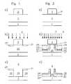
- Fig. 1schematically depict the steps of a prior art process for fabricating structures in a layer comprised of at least one polymer and capable of containing additives, depicted on a substrate.
- a layer 2 of a UV-crosslinking polymer and degradable by UV radiationOn a substrate 1 is according to Fig. 1a ) applied a layer 2 of a UV-crosslinking polymer and degradable by UV radiation and provided with a mask without gap.
- the irradiation according to Fig. 1b )takes place under protective gas with such a low radiation dose that only in a near-surface layer 21, 21 ' outside the mask 3, a cross-linking of the polymers occurs.
- the unirradiated layer 25 located underneath the mask 3is peeled off, while the further unirradiated layers 20, 20 ' as well as the near-surface layers 21, 21' remain standing.
- FIG. 2schematically the steps of the inventive method for the preparation of structures in a layer 2 on a substrate 1 using the example of polystyrene are shown.
- a solution of the UV-crosslinking and degradable by UV radiation polymer polystyreneis first applied in a solvent by means of spin, drip or dip. After evaporation of the solvent is formed according to Fig. 2 a) a polymer layer 2 on the surface of the substrate 1 from. Then, an irradiation mask 3 is placed on the surface of the polymer layer 2 and covered with a quartz glass plate, whereby a gap 31 between the irradiation mask 3 and the polymer layer 2 can remain.
- a radiation sourceis a mercury vapor lamp, the extent of which is substantially greater than that of the radiation mask 3 , to obtain a uniform illumination of the radiation mask 3 .
- the assemblyis mechanically reciprocated under the lamp to achieve uniform surface irradiation.
- a first part 23, 23 'of the polymeris removed in the areas in which the radiation mask 3 does not cover the polymer layer 2 , when it is irradiated under oxidative conditions 5 .
- a part 24, 24 'of the polymeris also removed.
- a modification of a second part 21, 21 'of the polymertakes place by cross-linking of the polymer chains with one another by means of a photoinduced radical reaction. If the irradiation 4 takes place under oxidative conditions 5, oxygen additionally oxidizes the surfaces 22, 22 'of the irradiated areas and is available for further chemical reactions (functionalization). In the remaining regions 20 , the polymer remains unchanged.
- the radiation mask 3removed from the irradiated arrangement and subjected to the remaining, already irradiated arrangement of the treatment 6 with a solvent.
- the solventis selected such that it does not dissolve the substrate 1 , that it only partially dissolves the second part 21, 21 ', 22, 22' of the layer and the unmodified part 25 of the layer, insofar as it is below the irradiation mask 3 was, dissolves.
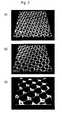
- Fig. 3the influence of the radiation dose and the distance between the mask 5 and the polymer layer 2 on the structures obtained after the development process is shown.
- Fig. 3 ashows a 100 .mu.m.times.100 .mu.m section of a structure of approximately 100 nm, which was produced by the method according to the invention.
- Fig. 3 bshows a further 100 .mu.m.times.100 .mu.m section from an approximately 100 nm high structure, which was produced by the method according to the invention.
- the preparationwas carried out as in the Fig. 3 a) Example shown, in which case the irradiation time with UV light from a 500 W mercury vapor lamp was 20 minutes.
- the open from above microcavitiesare limited by about 100 nm high walls and separated by microchannels.
- the cavitieswere formed by photolytic removal of polystyrene in those areas that were not covered by the mask.
- the channelswere created by dissolution of the chemically unmodified, ie masked, areas of the polystyrene layer by treatment with cyclohexane.
- the heights of the walls and thus the depth of the channels and cavitiesare limited by the height of the applied polymer layer.
- Fig. 3cshows another 50 .mu.m.times.50 .mu.m cutout from the same approximately 100 nm high structure as in FIG Fig. 3b ) , but at a position where the irradiation mask 3 had a distance 31 of a few ⁇ m from the polymer surface 2 .
- the walls of adjacent cavitiesare fused to each other due to the small distance of the mask 5 from the surface of the polymer 2 .
- Fig. 3cshows exemplified fused walls.
- the fusion in this caseis due to the near-surface crosslinking of the regions of the polymer layer 2 located between the walls under the radiation mask 3 . Due to the gap 31 between the radiation mask 3 and the polymer layer 2 , the crosslinking UV radiation could penetrate into this intermediate space and cause a modification of the surface of the polymer layer 2 .
- a comparisonshows that the depth of the cavities can be adjusted by the radiation dose.
- the space between two opposing wallsis shaped by the dose of radiation: the dose is chosen so that the opposite walls eventually touch and merge into a single wall, the width of which in turn depends on the radiation dose.
- Fig. 4demonstrates the influence of the geometry of the radiation mask 3 on the method according to the invention.
- Fig. 4a ) and a ')show images of the planar and the rounded sides of the transmission electron microscopy networks (TEM networks) used as masks.
- TEM networkstransmission electron microscopy networks
- the UV irradiationtakes place over 10 minutes at a distance of 17 cm between the lamp and the glass plate. Thereafter, the glass plate and mesh were removed and the AFM topographies were taken in accordance with Fig. 4b) and b ') at the approximately 100 nm high structures. Subsequently, the samples were rinsed with cyclohexane and placed at the identical sample sites as in Fig. 4b) and b ') again made AFM topographic images which are now in Fig. 3c) and c ') can be seen.
- the in the Fig. 4 b), c), b ') and c ') Cutouts showninclude 30 microns x 30 microns.
- Fig. 5demonstrates the influence of the type of rinsing liquid, in particular its dielectric constant and the polarity of its molecules on the resulting layer thickness. Shown is the layer thickness difference ⁇ H of UV-irradiated polymer surfaces before and after rinsing with rinsing liquids having different dielectric constants D.
- the rinsing fluidscyclohexane (CH), toluene (T), dichloromethane (DCM), chloroform (CHF), tetrahydrofuran (THF), methanol (MeOH), acetonitrile (AcN) and water (H 2 O) were used.
Landscapes
- Engineering & Computer Science (AREA)
- Physics & Mathematics (AREA)
- Chemical & Material Sciences (AREA)
- Nanotechnology (AREA)
- General Physics & Mathematics (AREA)
- Manufacturing & Machinery (AREA)
- Crystallography & Structural Chemistry (AREA)
- Analytical Chemistry (AREA)
- Condensed Matter Physics & Semiconductors (AREA)
- Microelectronics & Electronic Packaging (AREA)
- Mathematical Physics (AREA)
- Theoretical Computer Science (AREA)
- Manufacturing Of Printed Wiring (AREA)
- Treatments Of Macromolecular Shaped Articles (AREA)
- Micromachines (AREA)
- Application Of Or Painting With Fluid Materials (AREA)
- Preparing Plates And Mask In Photomechanical Process (AREA)
- Manufacturing Optical Record Carriers (AREA)
- Exposure And Positioning Against Photoresist Photosensitive Materials (AREA)
Abstract
Description
Translated fromGermanDie Erfindung betrifft ein Verfahren zur Strukturierung einer Schicht, die aus mindestens einem Polymer besteht und Additive enthalten kann, auf einem Substrat.The invention relates to a method for structuring a layer, which consists of at least one polymer and may contain additives, on a substrate.
In strahlungsinduzierten lithographischen Verfahren werden durch eine lokal selektive Bestrahlung von ausgewählten Bereichen Belichtungsmuster auf einer Oberflächenschicht erzeugt. Die weitere Prozessierung ist dadurch möglich, dass sich die bestrahlten und die nicht bestrahlten Bereiche der Schicht hinsichtlich ihres Verhaltens gegenüber mindestens einem Lösungsmittel voneinander unterscheiden. In Folge der unterschiedlichen Löslichkeit der bestrahlten und der nicht bestrahlten Bereiche gegenüber einer Anzahl von Lösungsmitteln lassen sich entweder die bestrahlten (Positivresist) oder die nicht bestrahlten Bereiche (Negativresist) der Oberflächenschicht selektiv lösen, wodurch die gewünschten Strukturen (Topologien) auf der Oberfläche entstehen.In radiation-induced lithographic processes, exposure patterns are generated on a surface layer by locally selective irradiation of selected areas. The further processing is possible in that the irradiated and the non-irradiated areas of the layer differ from one another with respect to their behavior towards at least one solvent. As a result of the different solubility of the irradiated and the non-irradiated areas compared to a number of solvents, either the irradiated (positive resist) or non-irradiated areas (negative resist) of the surface layer can be selectively dissolved, whereby the desired structures (topologies) are formed on the surface.
Aus dem Stand der Technik ist bekannt, die lokal selektive Bestrahlung entweder durchdirektes Schreiben, wobei ein fokussierter Laser- oder Elektronenstrahl über die zu strukturierende Oberflächenschicht geführt wird, oder durchMaskenlithographie, bei der eine Maske auf die zu strukturierende Oberflächenschicht gelegt und die Maske dann großflächig so bestrahlt wird, dass nur an den nicht abgedeckten Bereichen in der Oberflächenschicht eine Modifizierung des Materials stattfindet, auszuführen. Unabhängig vom gewählten Verfahren wird durch die lokal selektive Bestrahlung das Ausgangsmaterial der Oberflächenschichten (photo-)chemisch modifiziert oder durch die Strahlung vollständig abgetragen.It is known from the prior art, the locally selective irradiation either bydirect writing, wherein a focused laser or electron beam is guided over the surface layer to be structured, or bymask lithography, in which a mask placed on the surface layer to be structured and the mask is irradiated over a large area so that only at the uncovered areas in the surface layer, a modification of the material takes place to perform. Irrespective of the chosen method, the source material of the surface layers is (photo) chemically modified by the locally selective irradiation or completely removed by the radiation.
Die Belichtung von Schichten aus Photolacken mit ultraviolettem Licht (UV) durch Masken zur Erzeugung von Strukturen ist bekannt und wird insbesondere zur Herstellung von Strukturen auf Halbleiteroberflächen oder zur Herstellung von Masken für die Lithographie eingesetzt. Ebenso lassen sich mikrofluidische Systeme durch UV-Belichtung eines Substrats, das mit dem Photoresist-Lack SU-8 beschichtetet ist, durch eine Maske herstellen. In der optischen Polymertechnologie werden UV-lithographische Verfahren eingesetzt, um auf Substraten Polymerbahnen zu erzeugen, die als Lichtwellenleiter dienen.Exposure of layers of ultraviolet light (UV) photoresists through masks to form structures is is known and used in particular for the production of structures on semiconductor surfaces or for the production of masks for lithography. Similarly, microfluidic systems can be prepared by UV exposure of a substrate coated with photoresist SU-8 through a mask. In optical polymer technology, UV lithographic processes are used to produce polymeric webs on substrates that serve as optical fibers.
Aus
In
Weiterhin bekannt ist der Einsatz von Interferenztechnik bei der Bestrahlung lichtempfindlicher Schichten zur Erzeugung strukturierter Oberflächen. Die Bestrahlung eines Gitters mit Laserlicht erzeugt hinter dem Gitter ein Interferenzmuster, das auf die lichtempfindliche Schicht projiziert wird. Die durch die Maxima der Interferenz beleuchteten Bereiche auf der Schicht erfahren dabei eine photochemische Modifizierung.Also known is the use of interference technology in the irradiation of photosensitive layers to produce structured surfaces. Irradiation of a grating with laser light creates an interference pattern behind the grating which is projected onto the photosensitive layer. The areas illuminated by the maxima of the interference on the layer undergo a photochemical modification.
Die Lithographie mit Masken erzeugt Strukturen, deren laterale Dimensionen genau so groß sind wie die Dimensionen der Maskenstrukturen. Nachteilig hieran ist, dass insbesondere die Herstellung von Masken für Strukturen unterhalb von 100 nm einen immer höheren Aufwand erfordert. Zudem erfordert jede Änderung der Strukturgröße die Herstellung einer neuen Maske.The lithography with masks produces structures whose lateral dimensions are just as large as the dimensions of the mask structures. The disadvantage of this is that in particular the production of masks for structures below 100 nm requires an ever greater effort. In addition, any change in feature size requires the creation of a new mask.
Bei Einsatz der Laser- oder Elektronenstrahllithographie für dasdirekte Schreiben muss jede Position der Oberfläche, an der eine Struktur erzeugt werden soll, mit dem betreffenden Strahl individuell angefahren werden. Diese Voraussetzung verhindert die parallele Herstellung einer großen Zahl von Strukturen, so dass sich diese Verfahren nur zur Produktion von individuell strukturierten Substraten in geringer Stückzahl eignen. Zudem schränken lithographische Schreibverfahren die laterale Größe der strukturierbaren Oberfläche ein. Außerdem erfordern die herkömmlichen Verfahren einen hohen apparativen Aufwand wie z.B. Lichtausschluss bei Lichtlithographie oder Ultrahochvakuum in der Elektronenstrahllithographie.When using laser or electron beam lithography fordirect writing , each position of the surface on which a structure is to be produced must be approached individually with the relevant beam. This requirement prevents the parallel production of a large number of structures, so that these methods are only suitable for the production of individually structured substrates in small quantities. In addition, lithographic writing processes limit the lateral size of the patternable surface. In addition, the conventional methods require a high outlay on equipment such as, for example, light exclusion in light lithography or ultrahigh vacuum in electron beam lithography.
Die mit herkömmlichen lithographischen Verfahren hergestellten Strukturen sind auf ihren Oberflächen nicht chemisch funktionalisiert und müssen in einem gesonderten Schritt lokal selektiv chemisch funktionalisiert werden. Unterchemischer Funktionalisierung wird hierbei die Terminierung der Strukturoberfläche mit funktionellen bzw. chemisch reaktiven Gruppen verstanden, die sich dazu einsetzen lassen, die relevanten physikalischen Oberflächeneigenschaften wie hydrophob/hydrophil, polar/unpolar, fluoreszierend/nicht fluoreszierend usw. durch weitere chemische Reaktionen die Eigenschaften der Strukturoberflächen zu beeinflussen.The structures prepared by conventional lithographic processes are not chemically functionalized on their surfaces and must be locally selectively chemically functionalized in a separate step.Chemicalfunctionalization is here understood to mean the termination of the structural surface with functional or chemically reactive groups which can be used to determine the relevant physical surface properties such as hydrophobic / hydrophilic, polar / nonpolar, fluorescent / non-fluorescent, etc. by further chemical reactions to influence the structure surfaces.
Die
Ausgehend hiervon ist es die Aufgabe der vorliegenden Erfindung, ein Verfahren zur Strukturierung einer Schicht, die aus mindestens einem Polymer besteht und Additive enthalten kann, auf einem Substrat vorzuschlagen, das die genannten Nachteile und Einschränkungen nicht aufweist.Based on this, it is the object of the present invention to propose a method for structuring a layer, which consists of at least one polymer and may contain additives, on a substrate which does not have the stated disadvantages and limitations.
Insbesondere besteht die Aufgabe der Erfindung darin, ein Verfahren dieser Art bereit zu stellen, das bei einer niedrigen Zahl an Arbeitsschritten und bei geringem technischen und zeitlichen Aufwand die Herstellung von Strukturen mit Dimensionen von 1 nm bis 1000 µm und deren gleichzeitige chemische Funktionalisierung ermöglicht.In particular, the object of the invention is to provide a method of this kind which, with a low number of work steps and with little technical and time expenditure, the production of structures with dimensions from 1 nm to 1000 microns and their simultaneous chemical functionalization allows.
Eine weitere Aufgabe der Erfindung besteht darin, ein Verfahren dieser Art bereit zu stellen, das eine hohe Flexibilität sowohl im Hinblick auf Form und Material der Oberfläche als auch in Bezug auf die geometrischen Parameter (laterale und vertikale Ausdehnung; Abstände der Strukturen) zulässt.A further object of the invention is to provide a method of this kind which allows a high degree of flexibility both with regard to the shape and material of the surface and with regard to the geometric parameters (lateral and vertical extent, spacing of the structures).
Diese Aufgabe wird durch die Schritte des Anspruchs 1 gelöst. Die Unteransprüche beschreiben vorteilhafte Ausgestaltungen der Erfindung.This object is achieved by the steps of
Das erfindungsgemäße Verfahren umfasst die im Folgenden im Einzelnen erläuterten Schritte a) bis c).The process according to the invention comprises the steps a) to c) explained in detail below.
Gemäß Schritt a) wird zunächst eine Anordnung bereitgestellt, die
- ein Substrat und
- eine auf der Oberfläche des Substrats aufgebrachte Schicht umfasst, die aus einem Polymer oder mehreren Polymeren besteht, die darüber hinaus auch Additive enthalten kann und die bevorzugt, aber nicht notwendigerweise eben ist. Als Additiv eignen sich bevorzugt Substanzen, die eine wellenlängenselektive Bestrahlung und Modifizierung der Schicht ermöglichen.
- a substrate and
- comprises a layer applied to the surface of the substrate, which consists of one or more polymers, which may also contain additives and which is preferred but not necessarily planar. Substances which enable wavelength-selective irradiation and modification of the layer are preferably suitable as additive.
Die Oberflächenschicht wird nicht vollständig, sondern nur über ausgewählten Bereichen mit einer Maske abgedeckt. In einer bevorzugten Ausgestaltung ist die Maske so angeordnet, dass während der Bestrahlung gemäß Schritt b) ein Spalt zwischen der Schicht und der Maske verbleibt.The surface layer is not covered completely, but only over selected areas with a mask. In a preferred embodiment, the mask is arranged so that a gap remains between the layer and the mask during the irradiation according to step b).
Die Materialien, aus denen Schicht und Maske bestehen, werden so gewählt, dass das Polymer oder zumindest eines der Polymere, aus denen die Schicht besteht, durch Strahlung mindestens einer Frequenz aus dem elektromagnetischen Spektrum, vorzugsweise durch ultraviolette (UV) Strahlung, insbesondere mit einer Wellenlänge kleiner 350 nm, oder durch eine Teilchen-Strahlung modifizierbar ist, während die Maske für die gewählte Strahlung undurchlässig ist.The materials that make up the layer and mask are chosen so that the polymer or at least one of the polymers, of which the layer is made, by radiation of at least one frequency from the electromagnetic spectrum, preferably by ultraviolet (UV) radiation, in particular with a wavelength less than 350 nm, or modifiable by a particle radiation, while the mask for the selected radiation is impermeable ,
Als Substrat eignet sich eine Vielzahl von Materialien, solange sich diese in dem unter Schritt c) näher erläuterten Lösungsmittel nicht auflösen. Hierzu gehören metallische oder halbleitende Oberflächen sowie organische Materialien.The substrate is a variety of materials, as long as they do not dissolve in the solvent described in more detail in step c). These include metallic or semi-conductive surfaces as well as organic materials.
Anschließend wird die Anordnung gemäß Schritt b) durch die gewählte Strahlung beaufschlagt. Hierbei wird die Strahlendosis so eingestellt, dass die Schicht in Abhängigkeit von der Abdeckung durch die Maske das folgende Verhalten zeigt, wobei sich die Strahlendosis aus der Intensität der Strahlungsquelle, dem Abstand zwischen der Strahlungsquelle und der Oberfläche der Polymerschicht sowie der Dauer der Bestrahlung ergibt:
- In denjenigen Bereichen, in denen die Maske die Polymerschichtnicht abdeckt, trägt die Strahlung einen ersten Teil des Polymers ab, wobei der Abtrag an Material aus der Polymerschicht von der Höhe der in die Polymerschicht eingebrachten Strahlendosis abhängt.
- An den Rändern derjenigen Bereiche, in denen die Maske die Polymerschicht nicht abdeckt, aber noch unterhalb der Maske, wird ebenfalls ein Teil des Polymers abgetragen.
- An den Rändern der Bereiche, in denen die Strahlung die Polymerschicht abträgt, erfolgt z.B. durch photoinduzierte radikalische Reaktion eine Modifikation des zweiten Teils des Polymers durch Quervernetzung der Polymerketten untereinander. Die Vernetzung der Polymerketten findet jedoch höchstens bis zu einer Tiefe von wenigen Mikrometern statt, so dass sowohl die Oberflächen als auch das Kernmaterial der durch die Maske abgedeckten Bereiche der Polymerschicht chemisch unmodifiziert bleiben. Dieser Vorgang ist Ursache für die verringerte Löslichkeit des modifizierten Polymers in einem Lösungsmittel, das das unmodifizierte Polymer löst, bis hin zu einer vollständigen Unlöslichkeit des modifizierten Polymers.
- In den übrigen Bereichen bleibt das Polymer unverändert.
- In those areas in which the maskdoes not cover the polymer layer, the radiation carries off a first part of the polymer, wherein the removal of material from the polymer layer depends on the level of the radiation dose introduced into the polymer layer.
- At the edges of those areas where the mask does not cover the polymer layer, but still below the mask, a portion of the polymer is also removed.
- At the edges of the regions in which the radiation ablates the polymer layer, for example by photoinduced radical reaction, a modification of the second part of the polymer takes place by cross-linking of the polymer chains with one another. However, the crosslinking of the polymer chains takes place at most to a depth of a few micrometers, so that both the surfaces and the core material of the areas of the polymer layer covered by the mask are chemically unmodified stay. This process is responsible for the reduced solubility of the modified polymer in a solvent which dissolves the unmodified polymer to complete insolubility of the modified polymer.
- In the other areas, the polymer remains unchanged.
Während der Bestrahlung werden auf diese Weise kontinuierlich Seitenwände freigelegt, die dann ebenfalls der Strahlung ausgesetzt werden. So treten im Seitenwandbereich grundsätzlich gleichzeitig eine Vernetzung der Polymerketten und ein horizontaler Materialabtrag auf.During the irradiation side walls are exposed in this way continuously, which are then also exposed to the radiation. Thus, crosslinking of the polymer chains and horizontal material removal generally occur simultaneously in the sidewall region.
In einer bevorzugten Ausgestaltung findet die Bestrahlung der Anordnung unter oxidativen Bedingungen, besonders bevorzugt unter Normalbedingungen in Luft, statt. Durch den auf diese Weise bereitgestellten Sauerstoff werden die Oberflächen der bestrahlten Bereiche zusätzlich oxidiert und stehen so für weitere chemische Reaktionen zur Verfügung. Durch diesen Vorgang wird ein Teil des Polymers nicht nurmodifiziert, sondern darüber hinaus im selben Schritt auchfunktionalisiert.In a preferred embodiment, the irradiation of the arrangement takes place under oxidative conditions, more preferably under normal conditions in air. The oxygen provided in this way additionally oxidizes the surfaces of the irradiated areas, making them available for further chemical reactions. This process not onlymodifies a part of the polymer, but alsofunctionalizes it in the same step.
Weiterhin werden durch die Menge des zur Verfügung stehenden Sauerstoffs der Materialabtrag und damit die Tiefe der Kavitäten sowie die Höhe der Wände eingestellt. Die zur Verfügung stehende Sauerstoffmenge kann durch die Höhe der Maske oder durch den Anteil des Sauerstoffgehalts im Reaktionsgas eingestellt werden. Die maximal erreichbare Tiefe der Kavitäten und die maximal erreichbaren Höhen der Wände sind durch Wahl der Dicke der ursprünglichen Polymerschicht vorgegeben.Furthermore, the amount of available oxygen material removal and thus the depth of the cavities and the height of the walls are adjusted. The available amount of oxygen can be adjusted by the height of the mask or by the proportion of the oxygen content in the reaction gas. The maximum achievable depth of the cavities and the maximum achievable heights of the walls are predetermined by choosing the thickness of the original polymer layer.
In einer alternativen Ausgestaltung findet die Bestrahlung der Anordnung unter Schutzgas (Stickstoff, Argon) statt, um eine Oxidation der Schicht während der Bestrahlung zu vermeiden.In an alternative embodiment, the irradiation of the arrangement under protective gas (nitrogen, argon) takes place in order to avoid oxidation of the layer during irradiation.
Anschließend wird gemäß Schritt c) die Maske von der bestrahlten Anordnung entfernt und die nach der Entfernung der Maske verbleibende Anordnung mit einem Lösungsmittel behandelt. Das Lösungsmittel führt zur selektiven Auflösung von Teilen der nicht durch die Strahlung bereits abgetragenen Polymerschicht.Subsequently, according to step c), the mask is removed from the irradiated arrangement and the arrangement remaining after removal of the mask is treated with a solvent. The solvent leads to the selective dissolution of parts of the polymer layer not already removed by the radiation.
Es wird ein Lösungsmittel eingesetzt, das den folgenden Bedingungen genügt:
- Es löst das Substrat nicht auf.
- Es löst den zweiten Teil des Polymers, d.h. denjenigen Teil des Polymers, der durch die Bestrahlung in Schritt b) modifiziert wurde, höchstens teilweise auf.
- Es löst denjenigen Teil des Polymers, der nicht bestrahlt wurde oder der durch die Bestrahlung während Schritt b)nicht modifiziert wurde, nur insoweit auf, als sich dieser unterhalb der Maske befand.
- It does not dissolve the substrate.
- It at most partially dissolves the second part of the polymer, ie that part of the polymer which has been modified by the irradiation in step b).
- It dissolves that part of the polymer which was not irradiated or which wasnot modified by the irradiation during step b) only to the extent that it was below the mask.
Durch die Behandlung des Substrates mit einem derartigen Lösungsmittel bilden sich daher Wände aus, die eine Dicke von wenigen Mikrometern besitzen. Diese Wände bestehen aus dem zweiten Teil des Polymers, der durch die Bestrahlung in Schritt b) modifiziert wurde, und dem sich hierunter befindlichen nicht modifizierten Teil des Polymers.By treating the substrate with such a solvent, therefore, walls are formed which have a thickness of a few micrometers. These walls consist of the second part of the polymer modified by the irradiation in step b) and the unmodified part of the polymer underneath.
In einer bevorzugten Ausgestaltung wird die Anordnung sofort nach der Bestrahlung, während oder nach der Behandlung mit dem Lösungsmittel zusätzlich mit einer Spülflüssigkeit gespült wird, die weitere Bereiche aus dem zweiten Teil der Schicht auflöst. Bei geeigneter Wahl der Spülflüssigkeit wird so die Oberfläche der erfindungsgemäß hergestellten Struktur funktionalisiert. In einer besonders bevorzugten Ausgestaltung wird das Lösungsmittel gleichzeitig als Spülflüssigkeit eingesetzt.In a preferred embodiment, the arrangement is rinsed immediately after the irradiation, during or after the treatment with the solvent additionally with a rinsing liquid, which dissolves further areas from the second part of the layer. With a suitable choice of the rinsing liquid, the surface of the structure produced according to the invention is thus functionalized. In a particularly preferred embodiment, the solvent is used simultaneously as a rinsing liquid.
Der strahlungsinduzierte Materialabtrag eignet sich zur Strukturierung und zur Modifizierung von Polymeroberflächen. Die erfindungsgemäß hergestellten Wände bilden Strukturen, z.B. Begrenzungen für (Mikro-) Kavitäten und Kanäle mit Dimensionen von 1 nm bis 1000 µm, deren genaue Form von der Höhe der Oberflächenschicht, der Strahlendosis, dem eingesetzten Lösungsmittel bzw. der Spülflüssigkeit abhängen.Radiation-induced material removal is suitable for structuring and modifying polymer surfaces. The According to the invention produced walls form structures, eg boundaries for (micro) cavities and channels with dimensions of 1 nm to 1000 microns, the exact shape of the height of the surface layer, the radiation dose, the solvent used or the rinsing liquid depend.
Mit dem erfindungsgemäßen Verfahren hergestellte Strukturen eignen sich als Resists für Oberflächen-Ätzprozesse. Weiterhin eigenen sich Strukturen dieser Art zur spezifischen Adhäsion von biologischen und nicht-biologischen Molekülen oder von Partikeln und Zellen aller Art.Structures produced by the method according to the invention are suitable as resists for surface etching processes. Furthermore, structures of this type are suitable for the specific adhesion of biological and non-biological molecules or of particles and cells of all kinds.
In einer bevorzugten Ausgestaltung werden die mit dem erfindungsgemäßen Verfahren hergestellten Strukturen direkt als Stempeloberfläche zum direkten Stempeln (Hoch- oder Tiefstempeln) auf Oberflächen verwendet.In a preferred embodiment, the structures produced by the method according to the invention are used directly as a stamp surface for direct stamping (high or low stamping) on surfaces.
In einer besonderen Ausgestaltung werden die Zwischenräume der auf einer leitfähigen Oberfläche erzeugten Strukturen durch galvanische Abscheidungsprozesse mit anderen Materialien wie z.B. Metallen oder leitfähigen Polymeren gefüllt und für Replikationszwecke verwendet.In a particular embodiment, the interstices of the structures formed on a conductive surface are formed by electrodeposition processes with other materials such as e.g. Filled with metals or conductive polymers and used for replication purposes.
Die Bedeutung von Verfahren zur Oberflächenstrukturierung und zur chemischen Oberflächenfunktionalisierung nimmt sowohl im Bereich der regenerativen Medizin und der künstlichen Organe als auch im Bereich der Biologie(Lab-on-Chip Anwendungen) zu. Hierbei spielt die chemische Funktionalisierung mittels UV-Belichtung eine wichtige Rolle, die bereits zur Herstellung von funktionalisierten Oberflächen z.B. für die Zelladhäsion eingesetzt wird. Das Beispiel der Zelladhäsion macht deutlich, dass Adhäsionsvorgänge an Oberflächen nicht nur die geeignete chemische Funktionalisierung der Oberfläche erfordern, sondern dass auch geometrische Faktoren wie Größe und Verteilung der funktionalisierten Strukturen auf der Oberfläche entscheidenden Einfluss auf die Effizienz der Adhäsion besitzen.The importance of surface structuring and chemical surface functionalization is increasing both in the field of regenerative medicine and artificial organs as well as in the field of biology(lab-on-chip applications). Here, the chemical functionalization by means of UV exposure plays an important role, which is already used for the production of functionalized surfaces, for example for cell adhesion. The example of cell adhesion makes it clear that adhesion processes on surfaces not only require the appropriate chemical functionalization of the surface, but also that geometric factors such as size and distribution of the functionalized structures on the surface are decisive Have an influence on the adhesion efficiency.
Das erfindungsgemäße Verfahren weist insbesondere die im Folgenden erwähnten Vorteile auf.
- Das erfindungsgemäße Verfahren zeichnet sich dadurch aus, dass mit derselben Maske lediglich durch Wahl der Strahlendosis und Variation der Bestrahlungs-Parameter Strukturen hergestellt werden können, deren Dimensionen um den Faktor 1-100 kleiner sind als die der Maskenstrukturen. Zudem lassen sich die Dimensionen der Strukturen sehr einfach durch Variation der Bestrahlungs-Parameter ändern. So lassen sich mit Maskenstrukturen im Mikrometerbereich Strukturen im Submikrometerbereich herstellen. Der Einsatz von Masken erlaubt die gleichzeitige, parallele Herstellung einer Vielzahl von Strukturen.
- Bei der Bestrahlung unter oxidativen Bedingungen finden Strukturbildung und Funktionalisierung der Schicht gleichzeitig statt. Die aufwändige selektive chemische Funktionalisierung der Strukturoberflächen nach der Herstellung entfällt.
- Das erfindungsgemäße Verfahren ist kostengünstig, da sämtliche Arbeitsschritte unter Normalbedingungen (an Luft unter Normaldruck bei Raumtemperatur) durchgeführt werden können. Als Strahlungsquelle eignet sich u. a. Quecksilberdampflampe.
- The method according to the invention is characterized in that structures can be produced with the same mask only by selecting the radiation dose and varying the irradiation parameters whose dimensions are smaller by a factor of 1-100 than those of the mask structures. In addition, the dimensions of the structures can be changed very easily by varying the irradiation parameters. For example, structures in the submicron range can be produced with mask structures in the micrometer range. The use of masks allows the simultaneous, parallel production of a variety of structures.
- Upon irradiation under oxidative conditions, structure formation and functionalization of the layer occur simultaneously. The elaborate selective chemical functionalization of the structural surfaces after production is eliminated.
- The inventive method is inexpensive, since all steps under normal conditions (in air under normal pressure at room temperature) can be performed. The radiation source is, inter alia, mercury vapor lamp.
Die Erfindung wird im Folgenden anhand von Ausführungsbeispielen und den Figuren näher erläutert. Die Figuren zeigen:
- Fig. 1
- a) bis c) Schematische Darstellung der Schritte eines Strukturierungsverfahrens aus dem Stand der Technik.
- Fig. 2
- a) bis c) Schematische Darstellung der Schritte des erfindungsgemäßen Verfahrens.
- Fig. 3
- AFM Aufnahmen von Ausschnitten aus Strukturen, die mit dem erfindungsgemäßen Verfahren hergestellt wurden:
- a)
Bestrahlungszeit 1 Minute; Abstand Lampe - Glasplatte 17 cm; Maske hat direkten Kontakt zur Oberfläche der Polymerschicht;Ausschnitt 100 µm x 100 µm; - b) Bestrahlungszeit 20 Minuten; Abstand Lampe - Glasplatte 17 cm; Maske hat direkten Kontakt zur Oberfläche der Polymerschicht;
Ausschnitt 100 µm x 100 µm; - c) Bestrahlungszeit 20 Minuten; Abstand Lampe - Glasplatte 17 cm; Abstand Maske - Oberfläche der Polymerschicht einige Mikrometer; Ausschnitt 50 µm x 50 µm.
- a)
- Fig. 4
- a) und a') Konfokal-mikroskopische Aufnahmen von Transmissionselektronenmikrokopie-Netzen mit verschiedener Geometrie als Masken;
- b) und b') AFM-Aufnahmen von Strukturen vor der Spülung mit Cyclohexan;
- c) und c') AFM-Aufnahmen der Strukturen aus
Fig. 4 b) bzw.b') nach der Spülung mit Cyclohexan.
- Fig. 5
- Schichtdickendifferenz ΔH erfindungsgemäß hergestellter Strukturen vor und nach dem Spülen mit Spülflüssigkeit als Funktion der Dielektrizitätskonstanten D der Spülflüssigkeit Cyclohexan (CH), Toluol (T), Dichlormethan (DCM), Chloroform (ChF), Tetrahydrofuran (THF), Methanol (MeOH), Acetonitril (AcN) bzw. Wasser (H2O).
- Fig. 1
- a) to c) Schematic representation of the steps of a structuring method of the prior art.
- Fig. 2
- a) to c) Schematic representation of the steps of the method according to the invention.
- Fig. 3
- AFM footage of excerpts from structures using were prepared according to the method of the invention:
- a)
irradiation time 1 minute; Distance lamp - glass plate 17 cm; Mask has direct contact with the surface of the polymer layer;Section 100 μm x 100 μm; - b)
irradiation time 20 minutes; Distance lamp - glass plate 17 cm; Mask has direct contact with the surface of the polymer layer;Section 100 μm x 100 μm; - c)
irradiation time 20 minutes; Distance lamp - glass plate 17 cm; Distance mask - surface of the polymer layer a few micrometers; Cutout 50 μm x 50 μm.
- a)
- Fig. 4
- a) and a ') confocal micrographs of transmission electron microscopy networks with different geometry as masks;
- b) and b ') AFM images of structures before rinsing with cyclohexane;
- c) and c ') AFM images of the structures
Fig. 4b) orb ') after rinsing with cyclohexane.
- Fig. 5
- Layer thickness difference ΔH structures prepared according to the invention before and after rinsing with rinsing liquid as a function of the dielectric constant D of the rinsing liquid cyclohexane (CH), toluene (T), dichloromethane (DCM), chloroform (CHF), tetrahydrofuran (THF), methanol (MeOH), acetonitrile (AcN) or water (H2 O).
In
In
Auf ein Substrat1 wird zunächst eine Lösung des UV-vernetzenden und mittels UV-Strahlung abbaubaren Polymers Polystyrol in einem Lösungsmittel mittels Schleuder-, Tropf oder Tauchtechnik aufgebracht. Nach dem Verdunsten des Lösungsmittels bildet sich gemäß
Anschließend wird gemäß
Durch die Bestrahlung4 wird in den Bereichen, in denen die Bestrahlungsmaske3 die Polymerschicht2 nicht abdeckt, ein erster Teil23, 23' des Polymers abgetragen, wenn unter oxidativen Bedingungen5 bestrahlt wird. An den Rändern der Bereiche, in denen die Maske3 die Polymerschicht2 nicht abdeckt, aber noch unterhalb der Maske3, wird ebenfalls ein Teil24, 24' des Polymers abgetragen. An den Rändern der Bereiche, in denen die Strahlung die Polymerschicht abträgt, erfolgt durch photoinduzierte radikalische Reaktion eine Modifikation eines zweiten Teils21, 21' des Polymers durch Quervernetzung der Polymerketten untereinander. Findet die Bestrahlung4 unter oxidativen Bedingungen 5 statt, so oxidiert Sauerstoff die Oberflächen22, 22' der bestrahlten Bereiche zusätzlich und steht für weitere chemische Reaktionen (Funktionalisierung) zur Verfügung. In den übrigen Bereichen20 bleibt das Polymer unverändert.By the
Schließlich wird, wie in
In
Die in
Ein Vergleich zeigt, dass sich die Tiefe der Kavitäten durch die Strahlendosis einstellen lässt. Je höher die Dosis, umso mehr Material wird abgetragen, wie der direkte Vergleich von
Die Herstellung der in
Die UV-Bestrahlung erfolgt über 10 Minuten bei einem Abstand zwischen Lampe und Glasplatte von 17 cm. Danach wurden Glasplatte und Netz entfernt und die AFM-Topographieaufnahmen gemäß
- 11
- Substratsubstratum
- 22
- Schicht aus unbehandeltem Polymer (mit/ohne Additive)Layer of untreated polymer (with / without additives)
- 20, 20'20, 20 '
- Nicht entferntes unbehandeltes Polymer neben der MaskeUndressed untreated polymer next to the mask
- 21, 21'21, 21 '
- Schicht aus vernetztem PolymerLayer of crosslinked polymer
- 22, 22'22, 22 '
- Schicht aus oxidiertem PolymerLayer of oxidized polymer
- 23, 23'23, 23 '
- Durch strahlungsinduzierten Materialabtrag entferntes Polymer neben der MaskePolymer removed by radiation-induced material removal next to the mask
- 24, 24'24, 24 '
- Durch strahlungsinduzierten Materialabtrag entferntes Polymer unterhalb der MaskePolymer removed by radiation-induced material removal underneath the mask
- 2525
- Entferntes unbehandeltes Polymer unterhalb der MaskeRemoved untreated polymer below the mask
- 26, 26'26, 26 '
- Mit Lösungsmittel bzw. Spülflüssigkeit behandelte Schicht 21, 21' aus oxidiertem PolymerSolvent or rinse treated
layer 21, 21 'of oxidized polymer - 33
- (Bestrahlungs-)Maske(Irradiation) Mask
- 3131
- Abstand (Spalt) zwischen Maske 3 und Schicht 2Distance (gap) between
mask 3 andlayer 2 - 44
- Bestrahlung (bevorzugt UV-Strahlung)Irradiation (preferably UV radiation)
- 55
- Oxidation in oxidativer AtmosphäreOxidation in oxidative atmosphere
- 66
- Behandlung mit LösungsmittelTreatment with solvent
Claims (8)
Translated fromGermanAbdecken von ausgewählten Bereichen der Schicht (2) durch eine Maske (3), wobei mindestens eines der Polymere der Schicht so gewählt ist, dass es durch elektromagnetische Strahlung oder Teilchen-Strahlung modifizierbar ist, für die die Maske (3) undurchlässig ist,
Covering selected areas of the layer (2) by a mask (3), wherein at least one of the polymers of the layer is selected to be modifiable by electromagnetic radiation or particle radiation for which the mask (3) is impermeable,
Applications Claiming Priority (1)
| Application Number | Priority Date | Filing Date | Title |
|---|---|---|---|
| DE102007007719ADE102007007719A1 (en) | 2007-02-16 | 2007-02-16 | Method for structuring a layer on a substrate |
Publications (3)
| Publication Number | Publication Date |
|---|---|
| EP1959298A2true EP1959298A2 (en) | 2008-08-20 |
| EP1959298A3 EP1959298A3 (en) | 2009-07-29 |
| EP1959298B1 EP1959298B1 (en) | 2010-06-16 |
Family
ID=39472590
Family Applications (1)
| Application Number | Title | Priority Date | Filing Date |
|---|---|---|---|
| EP08002496ANot-in-forceEP1959298B1 (en) | 2007-02-16 | 2008-02-12 | Method for structuring a layer onto a substrate |
Country Status (3)
| Country | Link |
|---|---|
| EP (1) | EP1959298B1 (en) |
| AT (1) | ATE471534T1 (en) |
| DE (2) | DE102007007719A1 (en) |
Citations (4)
| Publication number | Priority date | Publication date | Assignee | Title |
|---|---|---|---|---|
| US4414059A (en) | 1982-12-09 | 1983-11-08 | International Business Machines Corporation | Far UV patterning of resist materials |
| EP0810477A2 (en) | 1996-05-24 | 1997-12-03 | Texas Instruments Incorporated | Photoactive systems for high resolution photolithography |
| US6114082A (en) | 1996-09-16 | 2000-09-05 | International Business Machines Corporation | Frequency doubling hybrid photoresist having negative and positive tone components and method of preparing the same |
| WO2006056905A2 (en) | 2004-11-25 | 2006-06-01 | Koninklijke Philips Electronics N.V. | Lithographic method |
Family Cites Families (1)
| Publication number | Priority date | Publication date | Assignee | Title |
|---|---|---|---|---|
| US6743368B2 (en)* | 2002-01-31 | 2004-06-01 | Hewlett-Packard Development Company, L.P. | Nano-size imprinting stamp using spacer technique |
- 2007
- 2007-02-16DEDE102007007719Apatent/DE102007007719A1/ennot_activeWithdrawn
- 2008
- 2008-02-12DEDE502008000782Tpatent/DE502008000782D1/enactiveActive
- 2008-02-12ATAT08002496Tpatent/ATE471534T1/enactive
- 2008-02-12EPEP08002496Apatent/EP1959298B1/ennot_activeNot-in-force
Patent Citations (4)
| Publication number | Priority date | Publication date | Assignee | Title |
|---|---|---|---|---|
| US4414059A (en) | 1982-12-09 | 1983-11-08 | International Business Machines Corporation | Far UV patterning of resist materials |
| EP0810477A2 (en) | 1996-05-24 | 1997-12-03 | Texas Instruments Incorporated | Photoactive systems for high resolution photolithography |
| US6114082A (en) | 1996-09-16 | 2000-09-05 | International Business Machines Corporation | Frequency doubling hybrid photoresist having negative and positive tone components and method of preparing the same |
| WO2006056905A2 (en) | 2004-11-25 | 2006-06-01 | Koninklijke Philips Electronics N.V. | Lithographic method |
Non-Patent Citations (4)
| Title |
|---|
| A. HOZUMI ET AL., LANGMUIR, vol. 18, 2002, pages 9022 |
| A. HOZUMI; H. INAGAKI; T. KAMEYAMA, J. COLL. INT. SCI., vol. 278, 2004, pages 383 |
| AUS S. ASAKURA ET AL., THIN SOLID FILMS, vol. 500, 2006, pages 237 |
| T. LIPPERT ET AL.: "Development and structuring of combined positive-negative/ negative-positive resists using laser ablation as positive dry etching technique", MACROMOL. MATER. ENG, vol. 283, 2000, pages 140 - 143 |
Also Published As
| Publication number | Publication date |
|---|---|
| DE102007007719A1 (en) | 2008-08-21 |
| EP1959298B1 (en) | 2010-06-16 |
| DE502008000782D1 (en) | 2010-07-29 |
| ATE471534T1 (en) | 2010-07-15 |
| EP1959298A3 (en) | 2009-07-29 |
Similar Documents
| Publication | Publication Date | Title |
|---|---|---|
| DE2624832C3 (en) | Process for the production of resist samples | |
| DE69126586T2 (en) | Device manufacturing method | |
| EP0002795B1 (en) | Process for the fabrication of masks for lithographic processes using a photoresist | |
| DE69131878T2 (en) | Process for producing a phase shift photomask | |
| DE2655455C2 (en) | Method for producing a mask and lacquer structure for use in the method | |
| DE4300983C2 (en) | Etching process for the manufacture of a semiconductor device | |
| DE2627003A1 (en) | METHOD OF MANUFACTURING A SELF-SUPPORTING MASK USED FOR PROJECTION LITHOGRAPHY | |
| DE2754396A1 (en) | METHOD OF MANUFACTURING THIN FILM PATTERNS | |
| DE102009000642B4 (en) | Process for producing microstructured components by means of photolithography | |
| DE10197137B4 (en) | Process for the production of microstructures | |
| EP0141389A2 (en) | Process for the production of image-wise structured resists, and dry resist therefor | |
| DE4317925C2 (en) | Method of manufacturing a semiconductor device | |
| EP0222738A2 (en) | Process for the production of a transmission mask | |
| DE3337315C2 (en) | ||
| DE10309266B3 (en) | A method of forming an opening of a light absorbing layer on a mask | |
| WO2018114590A1 (en) | Process for the production of microstructures | |
| DE102006050363B4 (en) | A process for producing a photomask, a process for structuring a layer or a layer stack and resist stacks on a mask substrate | |
| DE10219122A1 (en) | Process for the production of hard masks | |
| EP1959298B1 (en) | Method for structuring a layer onto a substrate | |
| DE19857094B4 (en) | Method for reducing / locally reducing a resist pattern in a semiconductor device | |
| DE3588185T2 (en) | Process for the production of patterned photo protective lacquer layers | |
| DE2452326A1 (en) | METHOD OF MANUFACTURING AN ETCHING MASK USING ENERGY RADIATION | |
| DE10307523B4 (en) | Process for producing a resist mask for the patterning of semiconductor substrates | |
| DE2528666C2 (en) | Method of making a mask for X-ray lithography | |
| DE10106861C1 (en) | Production of fine resist structures in a photoresist layer during the manufacture of microelectronic components by applying a photoresist layer, applying and exposing 2 masks at different wavelengths and developing resist |
Legal Events
| Date | Code | Title | Description |
|---|---|---|---|
| PUAI | Public reference made under article 153(3) epc to a published international application that has entered the european phase | Free format text:ORIGINAL CODE: 0009012 | |
| AK | Designated contracting states | Kind code of ref document:A2 Designated state(s):AT BE BG CH CY CZ DE DK EE ES FI FR GB GR HR HU IE IS IT LI LT LU LV MC MT NL NO PL PT RO SE SI SK TR | |
| AX | Request for extension of the european patent | Extension state:AL BA MK RS | |
| PUAL | Search report despatched | Free format text:ORIGINAL CODE: 0009013 | |
| AK | Designated contracting states | Kind code of ref document:A3 Designated state(s):AT BE BG CH CY CZ DE DK EE ES FI FR GB GR HR HU IE IS IT LI LT LU LV MC MT NL NO PL PT RO SE SI SK TR | |
| AX | Request for extension of the european patent | Extension state:AL BA MK RS | |
| 17P | Request for examination filed | Effective date:20090708 | |
| RAP1 | Party data changed (applicant data changed or rights of an application transferred) | Owner name:KARLSRUHER INSTITUT FUER TECHNOLOGIE | |
| GRAP | Despatch of communication of intention to grant a patent | Free format text:ORIGINAL CODE: EPIDOSNIGR1 | |
| AKX | Designation fees paid | Designated state(s):AT BE BG CH CY CZ DE DK EE ES FI FR GB GR HR HU IE IS IT LI LT LU LV MC MT NL NO PL PT RO SE SI SK TR | |
| GRAS | Grant fee paid | Free format text:ORIGINAL CODE: EPIDOSNIGR3 | |
| GRAA | (expected) grant | Free format text:ORIGINAL CODE: 0009210 | |
| AK | Designated contracting states | Kind code of ref document:B1 Designated state(s):AT BE BG CH CY CZ DE DK EE ES FI FR GB GR HR HU IE IS IT LI LT LU LV MC MT NL NO PL PT RO SE SI SK TR | |
| REG | Reference to a national code | Ref country code:CH Ref legal event code:NV Representative=s name:ROTTMANN, ZIMMERMANN + PARTNER AG Ref country code:CH Ref legal event code:EP | |
| REG | Reference to a national code | Ref country code:IE Ref legal event code:FG4D Free format text:LANGUAGE OF EP DOCUMENT: GERMAN | |
| REF | Corresponds to: | Ref document number:502008000782 Country of ref document:DE Date of ref document:20100729 Kind code of ref document:P | |
| REG | Reference to a national code | Ref country code:NL Ref legal event code:VDEP Effective date:20100616 | |
| PG25 | Lapsed in a contracting state [announced via postgrant information from national office to epo] | Ref country code:LT Free format text:LAPSE BECAUSE OF FAILURE TO SUBMIT A TRANSLATION OF THE DESCRIPTION OR TO PAY THE FEE WITHIN THE PRESCRIBED TIME-LIMIT Effective date:20100616 Ref country code:SE Free format text:LAPSE BECAUSE OF FAILURE TO SUBMIT A TRANSLATION OF THE DESCRIPTION OR TO PAY THE FEE WITHIN THE PRESCRIBED TIME-LIMIT Effective date:20100616 Ref country code:NO Free format text:LAPSE BECAUSE OF FAILURE TO SUBMIT A TRANSLATION OF THE DESCRIPTION OR TO PAY THE FEE WITHIN THE PRESCRIBED TIME-LIMIT Effective date:20100916 | |
| LTIE | Lt: invalidation of european patent or patent extension | Effective date:20100616 | |
| PG25 | Lapsed in a contracting state [announced via postgrant information from national office to epo] | Ref country code:LV Free format text:LAPSE BECAUSE OF FAILURE TO SUBMIT A TRANSLATION OF THE DESCRIPTION OR TO PAY THE FEE WITHIN THE PRESCRIBED TIME-LIMIT Effective date:20100616 Ref country code:HR Free format text:LAPSE BECAUSE OF FAILURE TO SUBMIT A TRANSLATION OF THE DESCRIPTION OR TO PAY THE FEE WITHIN THE PRESCRIBED TIME-LIMIT Effective date:20100616 Ref country code:FI Free format text:LAPSE BECAUSE OF FAILURE TO SUBMIT A TRANSLATION OF THE DESCRIPTION OR TO PAY THE FEE WITHIN THE PRESCRIBED TIME-LIMIT Effective date:20100616 Ref country code:SI Free format text:LAPSE BECAUSE OF FAILURE TO SUBMIT A TRANSLATION OF THE DESCRIPTION OR TO PAY THE FEE WITHIN THE PRESCRIBED TIME-LIMIT Effective date:20100616 | |
| PG25 | Lapsed in a contracting state [announced via postgrant information from national office to epo] | Ref country code:PL Free format text:LAPSE BECAUSE OF FAILURE TO SUBMIT A TRANSLATION OF THE DESCRIPTION OR TO PAY THE FEE WITHIN THE PRESCRIBED TIME-LIMIT Effective date:20100616 Ref country code:CY Free format text:LAPSE BECAUSE OF FAILURE TO SUBMIT A TRANSLATION OF THE DESCRIPTION OR TO PAY THE FEE WITHIN THE PRESCRIBED TIME-LIMIT Effective date:20100616 | |
| REG | Reference to a national code | Ref country code:IE Ref legal event code:FD4D | |
| PG25 | Lapsed in a contracting state [announced via postgrant information from national office to epo] | Ref country code:NL Free format text:LAPSE BECAUSE OF FAILURE TO SUBMIT A TRANSLATION OF THE DESCRIPTION OR TO PAY THE FEE WITHIN THE PRESCRIBED TIME-LIMIT Effective date:20100616 Ref country code:EE Free format text:LAPSE BECAUSE OF FAILURE TO SUBMIT A TRANSLATION OF THE DESCRIPTION OR TO PAY THE FEE WITHIN THE PRESCRIBED TIME-LIMIT Effective date:20100616 Ref country code:IE Free format text:LAPSE BECAUSE OF FAILURE TO SUBMIT A TRANSLATION OF THE DESCRIPTION OR TO PAY THE FEE WITHIN THE PRESCRIBED TIME-LIMIT Effective date:20100616 | |
| PG25 | Lapsed in a contracting state [announced via postgrant information from national office to epo] | Ref country code:CZ Free format text:LAPSE BECAUSE OF FAILURE TO SUBMIT A TRANSLATION OF THE DESCRIPTION OR TO PAY THE FEE WITHIN THE PRESCRIBED TIME-LIMIT Effective date:20100616 Ref country code:IS Free format text:LAPSE BECAUSE OF FAILURE TO SUBMIT A TRANSLATION OF THE DESCRIPTION OR TO PAY THE FEE WITHIN THE PRESCRIBED TIME-LIMIT Effective date:20101016 Ref country code:RO Free format text:LAPSE BECAUSE OF FAILURE TO SUBMIT A TRANSLATION OF THE DESCRIPTION OR TO PAY THE FEE WITHIN THE PRESCRIBED TIME-LIMIT Effective date:20100616 Ref country code:SK Free format text:LAPSE BECAUSE OF FAILURE TO SUBMIT A TRANSLATION OF THE DESCRIPTION OR TO PAY THE FEE WITHIN THE PRESCRIBED TIME-LIMIT Effective date:20100616 | |
| PG25 | Lapsed in a contracting state [announced via postgrant information from national office to epo] | Ref country code:IT Free format text:LAPSE BECAUSE OF FAILURE TO SUBMIT A TRANSLATION OF THE DESCRIPTION OR TO PAY THE FEE WITHIN THE PRESCRIBED TIME-LIMIT Effective date:20100616 | |
| PLBE | No opposition filed within time limit | Free format text:ORIGINAL CODE: 0009261 | |
| STAA | Information on the status of an ep patent application or granted ep patent | Free format text:STATUS: NO OPPOSITION FILED WITHIN TIME LIMIT | |
| PG25 | Lapsed in a contracting state [announced via postgrant information from national office to epo] | Ref country code:DK Free format text:LAPSE BECAUSE OF FAILURE TO SUBMIT A TRANSLATION OF THE DESCRIPTION OR TO PAY THE FEE WITHIN THE PRESCRIBED TIME-LIMIT Effective date:20100616 | |
| 26N | No opposition filed | Effective date:20110317 | |
| PG25 | Lapsed in a contracting state [announced via postgrant information from national office to epo] | Ref country code:GR Free format text:LAPSE BECAUSE OF FAILURE TO SUBMIT A TRANSLATION OF THE DESCRIPTION OR TO PAY THE FEE WITHIN THE PRESCRIBED TIME-LIMIT Effective date:20100917 | |
| REG | Reference to a national code | Ref country code:DE Ref legal event code:R097 Ref document number:502008000782 Country of ref document:DE Effective date:20110316 | |
| BERE | Be: lapsed | Owner name:KARLSRUHER INSTITUT FUR TECHNOLOGIE Effective date:20110228 | |
| REG | Reference to a national code | Ref country code:CH Ref legal event code:PFA Owner name:KARLSRUHER INSTITUT FUER TECHNOLOGIE Free format text:KARLSRUHER INSTITUT FUER TECHNOLOGIE#KAISERSTRASSE 12#76131 KARLSRUHE (DE) -TRANSFER TO- KARLSRUHER INSTITUT FUER TECHNOLOGIE#KAISERSTRASSE 12#76131 KARLSRUHE (DE) | |
| PG25 | Lapsed in a contracting state [announced via postgrant information from national office to epo] | Ref country code:MC Free format text:LAPSE BECAUSE OF NON-PAYMENT OF DUE FEES Effective date:20110228 | |
| PG25 | Lapsed in a contracting state [announced via postgrant information from national office to epo] | Ref country code:BE Free format text:LAPSE BECAUSE OF NON-PAYMENT OF DUE FEES Effective date:20110228 | |
| PG25 | Lapsed in a contracting state [announced via postgrant information from national office to epo] | Ref country code:MT Free format text:LAPSE BECAUSE OF FAILURE TO SUBMIT A TRANSLATION OF THE DESCRIPTION OR TO PAY THE FEE WITHIN THE PRESCRIBED TIME-LIMIT Effective date:20100616 | |
| PG25 | Lapsed in a contracting state [announced via postgrant information from national office to epo] | Ref country code:LU Free format text:LAPSE BECAUSE OF NON-PAYMENT OF DUE FEES Effective date:20110212 | |
| PG25 | Lapsed in a contracting state [announced via postgrant information from national office to epo] | Ref country code:PT Free format text:LAPSE BECAUSE OF NON-PAYMENT OF DUE FEES Effective date:20100616 | |
| PG25 | Lapsed in a contracting state [announced via postgrant information from national office to epo] | Ref country code:BG Free format text:LAPSE BECAUSE OF FAILURE TO SUBMIT A TRANSLATION OF THE DESCRIPTION OR TO PAY THE FEE WITHIN THE PRESCRIBED TIME-LIMIT Effective date:20100916 Ref country code:TR Free format text:LAPSE BECAUSE OF FAILURE TO SUBMIT A TRANSLATION OF THE DESCRIPTION OR TO PAY THE FEE WITHIN THE PRESCRIBED TIME-LIMIT Effective date:20100616 | |
| PG25 | Lapsed in a contracting state [announced via postgrant information from national office to epo] | Ref country code:ES Free format text:LAPSE BECAUSE OF FAILURE TO SUBMIT A TRANSLATION OF THE DESCRIPTION OR TO PAY THE FEE WITHIN THE PRESCRIBED TIME-LIMIT Effective date:20100927 Ref country code:HU Free format text:LAPSE BECAUSE OF FAILURE TO SUBMIT A TRANSLATION OF THE DESCRIPTION OR TO PAY THE FEE WITHIN THE PRESCRIBED TIME-LIMIT Effective date:20100616 | |
| REG | Reference to a national code | Ref country code:AT Ref legal event code:MM01 Ref document number:471534 Country of ref document:AT Kind code of ref document:T Effective date:20130212 | |
| PGFP | Annual fee paid to national office [announced via postgrant information from national office to epo] | Ref country code:CH Payment date:20140220 Year of fee payment:7 Ref country code:DE Payment date:20140220 Year of fee payment:7 | |
| PG25 | Lapsed in a contracting state [announced via postgrant information from national office to epo] | Ref country code:AT Free format text:LAPSE BECAUSE OF NON-PAYMENT OF DUE FEES Effective date:20130212 | |
| PGFP | Annual fee paid to national office [announced via postgrant information from national office to epo] | Ref country code:FR Payment date:20140218 Year of fee payment:7 | |
| PGFP | Annual fee paid to national office [announced via postgrant information from national office to epo] | Ref country code:GB Payment date:20140220 Year of fee payment:7 | |
| REG | Reference to a national code | Ref country code:DE Ref legal event code:R119 Ref document number:502008000782 Country of ref document:DE | |
| REG | Reference to a national code | Ref country code:CH Ref legal event code:PL | |
| GBPC | Gb: european patent ceased through non-payment of renewal fee | Effective date:20150212 | |
| PG25 | Lapsed in a contracting state [announced via postgrant information from national office to epo] | Ref country code:LI Free format text:LAPSE BECAUSE OF NON-PAYMENT OF DUE FEES Effective date:20150228 Ref country code:CH Free format text:LAPSE BECAUSE OF NON-PAYMENT OF DUE FEES Effective date:20150228 | |
| REG | Reference to a national code | Ref country code:FR Ref legal event code:ST Effective date:20151030 | |
| PG25 | Lapsed in a contracting state [announced via postgrant information from national office to epo] | Ref country code:GB Free format text:LAPSE BECAUSE OF NON-PAYMENT OF DUE FEES Effective date:20150212 Ref country code:DE Free format text:LAPSE BECAUSE OF NON-PAYMENT OF DUE FEES Effective date:20150901 | |
| PG25 | Lapsed in a contracting state [announced via postgrant information from national office to epo] | Ref country code:FR Free format text:LAPSE BECAUSE OF NON-PAYMENT OF DUE FEES Effective date:20150302 |