EP1956375A1 - Wind turbine and method determining at least one rotation parameter of a wind turbine rotor - Google Patents
Wind turbine and method determining at least one rotation parameter of a wind turbine rotorDownload PDFInfo
- Publication number
- EP1956375A1 EP1956375A1EP08009630AEP08009630AEP1956375A1EP 1956375 A1EP1956375 A1EP 1956375A1EP 08009630 AEP08009630 AEP 08009630AEP 08009630 AEP08009630 AEP 08009630AEP 1956375 A1EP1956375 A1EP 1956375A1
- Authority
- EP
- European Patent Office
- Prior art keywords
- rotor
- wind turbine
- phase
- angular frequency
- centrifugal force
- Prior art date
- Legal status (The legal status is an assumption and is not a legal conclusion. Google has not performed a legal analysis and makes no representation as to the accuracy of the status listed.)
- Granted
Links
Images

Classifications
- G—PHYSICS
- G01—MEASURING; TESTING
- G01P—MEASURING LINEAR OR ANGULAR SPEED, ACCELERATION, DECELERATION, OR SHOCK; INDICATING PRESENCE, ABSENCE, OR DIRECTION, OF MOVEMENT
- G01P3/00—Measuring linear or angular speed; Measuring differences of linear or angular speeds
- G01P3/02—Devices characterised by the use of mechanical means
- G01P3/16—Devices characterised by the use of mechanical means by using centrifugal forces of solid masses
- G01P3/22—Devices characterised by the use of mechanical means by using centrifugal forces of solid masses transferred to the indicator by electric or magnetic means
- F—MECHANICAL ENGINEERING; LIGHTING; HEATING; WEAPONS; BLASTING
- F03—MACHINES OR ENGINES FOR LIQUIDS; WIND, SPRING, OR WEIGHT MOTORS; PRODUCING MECHANICAL POWER OR A REACTIVE PROPULSIVE THRUST, NOT OTHERWISE PROVIDED FOR
- F03D—WIND MOTORS
- F03D17/00—Monitoring or testing of wind motors, e.g. diagnostics
- G—PHYSICS
- G01—MEASURING; TESTING
- G01P—MEASURING LINEAR OR ANGULAR SPEED, ACCELERATION, DECELERATION, OR SHOCK; INDICATING PRESENCE, ABSENCE, OR DIRECTION, OF MOVEMENT
- G01P21/00—Testing or calibrating of apparatus or devices covered by the preceding groups
- G01P21/02—Testing or calibrating of apparatus or devices covered by the preceding groups of speedometers
- G—PHYSICS
- G01—MEASURING; TESTING
- G01P—MEASURING LINEAR OR ANGULAR SPEED, ACCELERATION, DECELERATION, OR SHOCK; INDICATING PRESENCE, ABSENCE, OR DIRECTION, OF MOVEMENT
- G01P3/00—Measuring linear or angular speed; Measuring differences of linear or angular speeds
- G01P3/02—Devices characterised by the use of mechanical means
- G01P3/16—Devices characterised by the use of mechanical means by using centrifugal forces of solid masses
- G—PHYSICS
- G01—MEASURING; TESTING
- G01P—MEASURING LINEAR OR ANGULAR SPEED, ACCELERATION, DECELERATION, OR SHOCK; INDICATING PRESENCE, ABSENCE, OR DIRECTION, OF MOVEMENT
- G01P3/00—Measuring linear or angular speed; Measuring differences of linear or angular speeds
- G01P3/42—Devices characterised by the use of electric or magnetic means
- G01P3/44—Devices characterised by the use of electric or magnetic means for measuring angular speed
- F—MECHANICAL ENGINEERING; LIGHTING; HEATING; WEAPONS; BLASTING
- F05—INDEXING SCHEMES RELATING TO ENGINES OR PUMPS IN VARIOUS SUBCLASSES OF CLASSES F01-F04
- F05B—INDEXING SCHEME RELATING TO WIND, SPRING, WEIGHT, INERTIA OR LIKE MOTORS, TO MACHINES OR ENGINES FOR LIQUIDS COVERED BY SUBCLASSES F03B, F03D AND F03G
- F05B2260/00—Function
- F05B2260/82—Forecasts
- F05B2260/821—Parameter estimation or prediction
- F—MECHANICAL ENGINEERING; LIGHTING; HEATING; WEAPONS; BLASTING
- F05—INDEXING SCHEMES RELATING TO ENGINES OR PUMPS IN VARIOUS SUBCLASSES OF CLASSES F01-F04
- F05B—INDEXING SCHEME RELATING TO WIND, SPRING, WEIGHT, INERTIA OR LIKE MOTORS, TO MACHINES OR ENGINES FOR LIQUIDS COVERED BY SUBCLASSES F03B, F03D AND F03G
- F05B2270/00—Control
- F05B2270/10—Purpose of the control system
- F05B2270/101—Purpose of the control system to control rotational speed (n)
- F—MECHANICAL ENGINEERING; LIGHTING; HEATING; WEAPONS; BLASTING
- F05—INDEXING SCHEMES RELATING TO ENGINES OR PUMPS IN VARIOUS SUBCLASSES OF CLASSES F01-F04
- F05B—INDEXING SCHEME RELATING TO WIND, SPRING, WEIGHT, INERTIA OR LIKE MOTORS, TO MACHINES OR ENGINES FOR LIQUIDS COVERED BY SUBCLASSES F03B, F03D AND F03G
- F05B2270/00—Control
- F05B2270/30—Control parameters, e.g. input parameters
- F05B2270/327—Rotor or generator speeds
- F—MECHANICAL ENGINEERING; LIGHTING; HEATING; WEAPONS; BLASTING
- F05—INDEXING SCHEMES RELATING TO ENGINES OR PUMPS IN VARIOUS SUBCLASSES OF CLASSES F01-F04
- F05B—INDEXING SCHEME RELATING TO WIND, SPRING, WEIGHT, INERTIA OR LIKE MOTORS, TO MACHINES OR ENGINES FOR LIQUIDS COVERED BY SUBCLASSES F03B, F03D AND F03G
- F05B2270/00—Control
- F05B2270/30—Control parameters, e.g. input parameters
- F05B2270/329—Azimuth or yaw angle
- F—MECHANICAL ENGINEERING; LIGHTING; HEATING; WEAPONS; BLASTING
- F05—INDEXING SCHEMES RELATING TO ENGINES OR PUMPS IN VARIOUS SUBCLASSES OF CLASSES F01-F04
- F05B—INDEXING SCHEME RELATING TO WIND, SPRING, WEIGHT, INERTIA OR LIKE MOTORS, TO MACHINES OR ENGINES FOR LIQUIDS COVERED BY SUBCLASSES F03B, F03D AND F03G
- F05B2270/00—Control
- F05B2270/80—Devices generating input signals, e.g. transducers, sensors, cameras or strain gauges
- F05B2270/807—Accelerometers
Definitions
- the present inventionrelates to a wind turbine and method of determining at least one rotational parameter, such as rotation speed and phase of a wind turbine rotor.
- Wind turbinesare used to produce electrical power from the energy contained in blowing wind.
- the wind turbinecomprises a rotor which is driven by the wind and which in turn drives an induction generator, which usually is an AC generator.
- the electrical power output of the wind turbineneeds to be synchronized to this frequency.
- a conversion from the frequency produced in the generator to the frequency of the utility gridis necessary. This conversion is usually performed by transforming the AC voltage delivered by the generator into a DC voltage which is then transformed again into an AC voltage with fixed frequency. The AC voltage will then be fed into the utility grid.
- control systemsare used for controlling these values.
- the knowledge of the rotational speed and the phase angle of the rotori.e. the angle of a radial line extending from the rotor's center and rotating together with the rotor relative to a non-rotating reference line through the center of the rotor, is very useful.
- Variable speed wind turbines having a control mechanism for controlling the voltage fed into the utility gridare, e.g., disclosed in WO 2005/091490 A1 or US 5,083,039 .
- the rotational speed of the rotor and the phase angle of the rotorare usually measured inside the nacelle where the rotational speed is measured at a low-speed or high-speed shaft of the rotor by an inductive sensor.
- the phase angle of the rotoris usually measured by an absolute encoder placed at the end of the rotor's slip ring.
- the speed and the phase angleare measured in a local frame of reference, i.e. relative to the position of the wind turbines tower top. This leads to measurement errors if the tower top is moving. These measurement errors introduce an apparent cyclic oscillation of the measured rotor speed that is only in artefact. Any control mechanisms based on such measurement values include the risk of introducing artificial control requirements.
- the speed measurement at the high-speed shaftlacks information on the phase angle of the rotor and may include torsion oscillations.
- the measured effective centrifugal forcevaries during the rotation period of the rotor.
- the reason thereforeis that the measured effective centrifugal force is given by the sum of the actual centrifugal force, i.e. the centrifugal force resulting alone from the rotational movement of the rotor, and the projection of the gravitational force on the direction in which the actual centrifugal force is acting.
- This projectionvaries during a rotational cycle of the rotor. For example, when the rotor is in such a position that the centrifugal force acts on the reference object in a direction pointing towards the earth, then the measured effective centrifugal force is the sum of the absolute value of the actual centrifugal force and the absolute value of the gravitational force acting on the reference object.
- the measured effective centrifugal forceis the absolute value of the actual centrifugal force minus the absolute value of the gravitational force acting on the reference object.
- the value of the measured centrifugal forcelies between the two described values, which define a maximum value and a minimum value.
- the centrifugal force acting on the rotating reference objectis not a true force.
- the true forceis the so called centripetal force which acts towards the centre of the rotation and keeps the reference object moving on a circle of a fixed radius.
- the centrifugal forceis a fictitious force experienced by the reference object in the rotating coordinate system. It is due to the reference object's inertia and looks in the rotating coordinate system as if it would pull the reference object away from the center of rotation.
- the (real) force counter acting the (fictitious) centrifugal force, i.e. the reference object's inertia effect, for keeping the radius of the circle constantis the centripetal force.
- the centrifugal forcehas the same absolute value than the (fictitious) centrifugal force and is oriented in the opposite sense.
- the measurement of the centrifugal forceis therefore in fact a measurement of the centripetal force which is necessary to keep the reference object on its circle.
- the measurementwill still be referred to as measurement of a centrifugal force in the following.
- An effective centrifugal force acting in a second pre-determined directionwhich is defined in a coordinate system rotating synchronously with the rotor and which is not parallel to the first pre-determined direction, on at least one reference object located in or at the rotor is measured.
- the phase of the rotoris established.
- the phase of the rotationcan be determined.
- the frame of referenceis still a global frame of reference as the basis of establishing the phase is the vector of the gravitational force which always points towards the earth.
- determining of the phaseis easiest when the two non-parallel directions in which the effective centrifugal forces are measured are perpendicular to each other.
- the reference objectlocated in or at the hub of the rotor, i.e. near the rotor's rotation axis.
- the effective centrifugal forceoscillates about the value of the actual centrifugal force.
- the actual centrifugal forceproduces an offset in the oscillation which would lead to a DC offset in an AC electrical signal representing the measurement.
- the value of the actual centrifugal force acting on the reference objectdepends on the reference object's distance from the rotation axis. The bigger the distance of the reference object from the rotation axis is, the bigger is this offset.
- the actual centrifugal force, and therefore the offsetalso depends on the rotation speed.
- the rotor speedis also measured with reference to a global reference frame.
- a yaw rate gyroa spinning element is used.
- the spin axes of an undisturbed spinning elementhave, due to conservation of angular momentum, a fixed direction in space.
- the rotation speed of the rotoris measured by a disturbance on the spinning element which is caused by the rotation of the rotor.
- the disturbanceleads to a precession of the spin axis around the direction of the undisturbed spin axis which is the basis of the measurement of the rotors rotation speed.
- the measurement of the rotor speed with yaw rate gyrois performed in a global frame of reference.
- the angular frequency of the rotating rotorcan be established with certain degree of noise.
- the average angular frequencycan be established very precisely. Therefore, if only a precise average value for the rotor's angular frequency is needed to be established, this could be realized without the measurement by the yaw rate gyro.
- the average angular frequency established by the yaw rate gyrois not as precise as the value established by use of the measured effective centrifugal force.
- the measurement of the yaw rate gyrois corrected by comparing it to the angular frequency established on the basis of the measured effective centrifugal force in order to achieve a precise average value for the angular frequency of the rotor with little noise.
- a precise average value for the rotor' angular frequencyis not needed, establishing the angular frequency could be realized without the measurement of the effective centrifugal force.
- phase locked loopAs suitable means for calculating the angular frequency and/or the phase of the rotating rotor from the measured effective centrifugal force or forces is a phase locked loop (PLL).
- PLLphase locked loop
- an electrical signal representing the measured effective centrifugal forceis produced for each measured effective centrifugal force and fed into the phase locked loop.
- the first angular frequency and/or the phase of the rotorare/is then established by the phase locked loop.
- the phase locked loopmy either be implemented as a hardware module or a software module, e.g. in a digital signal processor.
- an effective centrifugal forcecan be measured with the accelerometer which can then be used in the inventive method.
- the accelerometeris located in or at the hub of the rotor. In this case an offset in the oscillations of the measured effective centrifugal force due to the actual centrifugal force can be kept small.
- the phase of the rotorcan also be established according to the inventive method. It shall be noted that the phase can also be established if two accelerometers or more are used instead of a dual-axis accelerometer as long as at least two accelerometers measure the effective centrifugal force in two different, non-parallel directions.
- a means which comprises a phase locked loopcan be used as a processing means for establishing the rotation speed and/or phase of the rotor.
- FIG. 1A typical wind turbine is shown in Fig. 1 .
- the wind turbine 1comprises a tower 2 which rests on a fundament in the ground 3 and at the top of the tower, a rotor 4.
- the rotoris equipped with three rotor blades 5 which are suspended in a rotor hub 6 which in turn is anchored in a nacelle 7 located at the top of the tower 2.
- the wind turbine 1 shown in Fig. 1rests on the ground it is also possible that it rests on a platform anchored in the seabed.
- the rotor 4 in Fig. 1has three rotor blades 5 it may have any number of rotor blades, i.e. at least one rotor blade. However, rotors with two and in particular with three rotor blades are most commonly used.
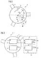
- Fig. 2shows, in a highly schematic view, a rotor hub 6 of the rotor 4. Close to the center of the rotor hub 6, a dual-axis accelerometer 10 is fixed to the hub. A yaw rate gyro 14 (see Fig. 3 ) is also fixed to the hub.
- a force on a reference object 11leads to a deflection of the reference object 11 which in turn gives a measure for the strength of the force acting on the reference object 11.
- forcescan be measured which act in perpendicular directions.
- the accelerometer 10rotates together with the rotor 4. The rotation leads to a centrifugal force on the at least one reference object.
- an effective centrifugal force F x in a first direction and an effective centrifugal force F y in a second direction perpendicular to the first directioncan be measured.
- These effective centrifugal forcesare the projection of the vector sum of the respective actual centrifugal force F' x , F' y and the gravitational Force Fg acting on the reference object in the direction of the respective actual centrifugal force F' x , F' y .
- the strengths of the resulting forces F x , F ywhich are referred to as effective centrifugal forces throughout the present invention, depend on the direction in which actual centrifugal forces F' x , F' y are acting.
- the accelerometer 10measures oscillating effective centrifugal forces F x , F y oscillating about the value of the actual centrifugal forces F' x , F' y .
- Fig. 3shows a processing means 18 for determining the rotation speed of the rotor 4 in form of a block diagram.
- the processing means 18,which is implemented as a digital signal processor in the present embodiment, comprises, as main components, a phase locked loop 12 connected to the output of the accelerometer 10 and an auto calibration unit 16 connected to the output of the yaw rate gyro 14 and the output of the phase locked loop 12.
- the first angular frequency ⁇ PLLis relatively noisy, even if the reference object 11 is located close to the rotation axis of the rotor 4.
- the average value for the first angular frequency ⁇ PLLis highly precise.
- a second angular frequency ⁇ yrgis established by the yaw rate gyro 14. Compared to the first angular frequency ⁇ PLL this second angular frequency ⁇ yrg is less noisy. However the average value, if averaged over time, is less precise than the average value for the first angular frequency ⁇ PLL .
- an electrical signal representing the second angular frequency ⁇ yrgis fed from the output of the yaw rate gyro into the auto calibration unit 16 into which also an output signal from the phase locked loop representing the first angular frequency ⁇ PLL is fed for calibrating the electrical signal representing the second angular frequency ⁇ yrg .
- the result of the calibrationis an electrical output signal of the processing means 18 which represents in turn the third angular frequency ⁇ rotor which in turn represents the actual rotor speed ⁇ rotor of the rotor 4.
- the inventive method and the inventive wind turbine measurement errorsare caused by tower top movement.
Landscapes
- Physics & Mathematics (AREA)
- General Physics & Mathematics (AREA)
- Engineering & Computer Science (AREA)
- Life Sciences & Earth Sciences (AREA)
- Sustainable Development (AREA)
- Sustainable Energy (AREA)
- Chemical & Material Sciences (AREA)
- Combustion & Propulsion (AREA)
- Mechanical Engineering (AREA)
- General Engineering & Computer Science (AREA)
- Wind Motors (AREA)
Abstract
Description
- The present invention relates to a wind turbine and method of determining at least one rotational parameter, such as rotation speed and phase of a wind turbine rotor.
- Wind turbines are used to produce electrical power from the energy contained in blowing wind. The wind turbine comprises a rotor which is driven by the wind and which in turn drives an induction generator, which usually is an AC generator.
- When the wind turbine is connected to a utility grid which requires a certain frequency, e.g. 50 Hz in Europe, the electrical power output of the wind turbine needs to be synchronized to this frequency. As modern wind turbines often work with variable rotational speed of the rotor and thus of the AC induction generator a conversion from the frequency produced in the generator to the frequency of the utility grid is necessary. This conversion is usually performed by transforming the AC voltage delivered by the generator into a DC voltage which is then transformed again into an AC voltage with fixed frequency. The AC voltage will then be fed into the utility grid.
- To keep the frequency and the voltage fed into the utility grid in tolerable ranges, control systems are used for controlling these values. For the calculations performed with regard to such controlling the knowledge of the rotational speed and the phase angle of the rotor, i.e. the angle of a radial line extending from the rotor's center and rotating together with the rotor relative to a non-rotating reference line through the center of the rotor, is very useful. Variable speed wind turbines having a control mechanism for controlling the voltage fed into the utility grid are, e.g., disclosed in
WO 2005/091490 A1 orUS 5,083,039 . - The rotational speed of the rotor and the phase angle of the rotor are usually measured inside the nacelle where the rotational speed is measured at a low-speed or high-speed shaft of the rotor by an inductive sensor. The phase angle of the rotor is usually measured by an absolute encoder placed at the end of the rotor's slip ring. However, in these measurements the speed and the phase angle are measured in a local frame of reference, i.e. relative to the position of the wind turbines tower top. This leads to measurement errors if the tower top is moving. These measurement errors introduce an apparent cyclic oscillation of the measured rotor speed that is only in artefact. Any control mechanisms based on such measurement values include the risk of introducing artificial control requirements. Moreover the speed measurement at the high-speed shaft lacks information on the phase angle of the rotor and may include torsion oscillations.
- Therefore it is an objective of the present invention to provide a method of determining at least one rotation parameter of a wind turbine rotor. It is a further objective of the present invention to provide an improved wind turbine, which in particular allows an improved measurement of at least one rotation parameter of its rotor.
- The mentioned objectives are solved by a method of determining at least one rotation parameter of a wind turbine rotor, as claimed in claim 1, and by a wind turbine, as claimed in claim 7. The depending claims define further developments of the present invention.
- The measured effective centrifugal force varies during the rotation period of the rotor. The reason therefore is that the measured effective centrifugal force is given by the sum of the actual centrifugal force, i.e. the centrifugal force resulting alone from the rotational movement of the rotor, and the projection of the gravitational force on the direction in which the actual centrifugal force is acting. This projection varies during a rotational cycle of the rotor. For example, when the rotor is in such a position that the centrifugal force acts on the reference object in a direction pointing towards the earth, then the measured effective centrifugal force is the sum of the absolute value of the actual centrifugal force and the absolute value of the gravitational force acting on the reference object. When, on the other hand, the rotor is in such a position that the actual centrifugal force is acting on the reference object in a direction which points away from the earth by 180° then the measured effective centrifugal force is the absolute value of the actual centrifugal force minus the absolute value of the gravitational force acting on the reference object. In between those two stages of the rotation the value of the measured centrifugal force lies between the two described values, which define a maximum value and a minimum value. As a consequence, the measured effective centrifugal force oscillates around the actual centrifugal force when the rotor is rotating. As the direction in which the gravitational force, which causes these oscillations, always points towards the earth the rotation is measured relative to the earth as global reference frame.
- It shall be noted that the centrifugal force acting on the rotating reference object is not a true force. The true force is the so called centripetal force which acts towards the centre of the rotation and keeps the reference object moving on a circle of a fixed radius. The centrifugal force is a fictitious force experienced by the reference object in the rotating coordinate system. It is due to the reference object's inertia and looks in the rotating coordinate system as if it would pull the reference object away from the center of rotation. The (real) force counter acting the (fictitious) centrifugal force, i.e. the reference object's inertia effect, for keeping the radius of the circle constant is the centripetal force. Hence, if the radius of the circle is kept constant, the centrifugal force has the same absolute value than the (fictitious) centrifugal force and is oriented in the opposite sense. The measurement of the centrifugal force is therefore in fact a measurement of the centripetal force which is necessary to keep the reference object on its circle. However, as the measured centripetal force differs from the centrifugal force only in its sign the measurement will still be referred to as measurement of a centrifugal force in the following.
- An effective centrifugal force acting in a second pre-determined direction, which is defined in a coordinate system rotating synchronously with the rotor and which is not parallel to the first pre-determined direction, on at least one reference object located in or at the rotor is measured. On the basis of the measured effective centrifugal forces acting in the first and second directions the phase of the rotor is established. When measuring only an effective centrifugal force in a single direction it is not possible to establish the phase. The reason is that the direction the gravitational force is directing in gets lost when only its projection on one direction of the rotating coordinate system is determined. With measuring the effective centrifugal force in a second non-parallel direction it is possible also to determine the vector of the gravitational force with respect to the rotating coordinate system, i.e. direction the gravitational force is directing in with reference to the rotating coordinate system. From the direction the gravitational force is acting in with respect to the rotating coordinate system, the phase of the rotation can be determined. Please note that although the vector components of the gravitational force are determined in the rotating coordinate system the frame of reference is still a global frame of reference as the basis of establishing the phase is the vector of the gravitational force which always points towards the earth. Please note that determining of the phase is easiest when the two non-parallel directions in which the effective centrifugal forces are measured are perpendicular to each other.
- It is desirable to have the reference object located in or at the hub of the rotor, i.e. near the rotor's rotation axis. As it has already been mentioned before, the effective centrifugal force oscillates about the value of the actual centrifugal force. Hence, the actual centrifugal force produces an offset in the oscillation which would lead to a DC offset in an AC electrical signal representing the measurement. The value of the actual centrifugal force acting on the reference object, however, depends on the reference object's distance from the rotation axis. The bigger the distance of the reference object from the rotation axis is, the bigger is this offset. In addition, the actual centrifugal force, and therefore the offset, also depends on the rotation speed. Hence, the dependence on the rotation speed introduces additional variations in the result of the measurement. These variations increase with increasing distance of the reference object from the rotation axis and need to be taken into account when establishing the rotational frequency unless the reference object is positioned sufficiently close to the rotation axis.
- When the rotation speed is measured by a yaw rate gyro the rotor speed is also measured with reference to a global reference frame. In a yaw rate gyro a spinning element is used. The spin axes of an undisturbed spinning element have, due to conservation of angular momentum, a fixed direction in space. The rotation speed of the rotor is measured by a disturbance on the spinning element which is caused by the rotation of the rotor. The disturbance leads to a precession of the spin axis around the direction of the undisturbed spin axis which is the basis of the measurement of the rotors rotation speed. As a consequence the measurement of the rotor speed with yaw rate gyro is performed in a global frame of reference.
- By the use of the measured effective centrifugal force the angular frequency of the rotating rotor can be established with certain degree of noise. However, the average angular frequency can be established very precisely. Therefore, if only a precise average value for the rotor's angular frequency is needed to be established, this could be realized without the measurement by the yaw rate gyro. On the other hand, in the yaw rate gyro's measurement values less noise is present but the average angular frequency established by the yaw rate gyro is not as precise as the value established by use of the measured effective centrifugal force. Therefore, the measurement of the yaw rate gyro is corrected by comparing it to the angular frequency established on the basis of the measured effective centrifugal force in order to achieve a precise average value for the angular frequency of the rotor with little noise. Such a value is very valuable for controlling the wind turbine. If a precise average value for the rotor' angular frequency is not needed, establishing the angular frequency could be realized without the measurement of the effective centrifugal force.
- As suitable means for calculating the angular frequency and/or the phase of the rotating rotor from the measured effective centrifugal force or forces is a phase locked loop (PLL). In this case, an electrical signal representing the measured effective centrifugal force is produced for each measured effective centrifugal force and fed into the phase locked loop. The first angular frequency and/or the phase of the rotor are/is then established by the phase locked loop. The phase locked loop my either be implemented as a hardware module or a software module, e.g. in a digital signal processor.
- In the inventive wind turbine, an effective centrifugal force can be measured with the accelerometer which can then be used in the inventive method.
- It is advantageous if the accelerometer is located in or at the hub of the rotor. In this case an offset in the oscillations of the measured effective centrifugal force due to the actual centrifugal force can be kept small.
- When the used accelerometer is a dual-axis accelerometer, the phase of the rotor can also be established according to the inventive method. It shall be noted that the phase can also be established if two accelerometers or more are used instead of a dual-axis accelerometer as long as at least two accelerometers measure the effective centrifugal force in two different, non-parallel directions.
- As a processing means for establishing the rotation speed and/or phase of the rotor a means which comprises a phase locked loop can be used.
- Further features, properties and advantages of the present invention will become clear by the following description of embodiments of the invention with reference to the accompanying drawings.
- Fig. 1
- shows a typical wind turbine.
- Fig. 2
- shows the forces acting on a reference object located in the rotor of a wind turbine.
- Fig. 3
- shows in form of block diagram a device for establishing rotor speed and rotor phase.
- A typical wind turbine is shown in
Fig. 1 . The wind turbine 1 comprises atower 2 which rests on a fundament in the ground 3 and at the top of the tower, a rotor 4. In the present embodiment, the rotor is equipped with threerotor blades 5 which are suspended in arotor hub 6 which in turn is anchored in a nacelle 7 located at the top of thetower 2. Although the wind turbine 1 shown inFig. 1 rests on the ground it is also possible that it rests on a platform anchored in the seabed. Moreover, although the rotor 4 inFig. 1 has threerotor blades 5 it may have any number of rotor blades, i.e. at least one rotor blade. However, rotors with two and in particular with three rotor blades are most commonly used. - For a control of the wind turbines 1 operations it is desirable to know the rotation speed and the phase of the rotor 4 in a global frame of references so that errors in establishing rotor speed and phase due to movements of the top of the
tower 2 can be avoided. A method of establishing rotor speed and phase in a global frame of reference will now be described with reference tofigures 2 and 3 . Fig. 2 shows, in a highly schematic view, arotor hub 6 of the rotor 4. Close to the center of therotor hub 6, a dual-axis accelerometer 10 is fixed to the hub. A yaw rate gyro 14 (seeFig. 3 ) is also fixed to the hub.- In the
accelerometer 10, a force on a reference object 11 leads to a deflection of the reference object 11 which in turn gives a measure for the strength of the force acting on the reference object 11. In the dual-axis accelerometer 10 forces can be measured which act in perpendicular directions. When the rotor 4 is rotating around its rotational axis theaccelerometer 10 rotates together with the rotor 4. The rotation leads to a centrifugal force on the at least one reference object. - With dual axis accelerometer an effective centrifugal force Fx in a first direction and an effective centrifugal force Fy in a second direction perpendicular to the first direction can be measured. These effective centrifugal forces are the projection of the vector sum of the respective actual centrifugal force F'x, F'y and the gravitational Force Fg acting on the reference object in the direction of the respective actual centrifugal force F'x, F'y. The strengths of the resulting forces Fx, Fy, which are referred to as effective centrifugal forces throughout the present invention, depend on the direction in which actual centrifugal forces F'x, F'y are acting. As the
accelerometer 10 rotates together with the rotor 4 these directions rotate too. Therefore the measured values of the effective centrifugal force Fx, Fy oscillate between a maximum value, when the direction of the respective actual centrifugal force F'x, F'y point towards the ground, and a minimum value, when the direction of the respective actual centrifugal force F'x, F'y point away from the ground. Thus theaccelerometer 10 measures oscillating effective centrifugal forces Fx, Fy oscillating about the value of the actual centrifugal forces F'x, F'y. By the oscillating values for Fx and Fy the rotation speed and the phase of rotation of the rotor 4 can be established as will be described with reference tofig. 3 . - Although a dual-
axis accelerometer 10 is used in the present embodiment, two accelerometers with non-parallel sensitive directions could be used as well. Further, if only the rotation speed is to be established it would be possible to only use one accelerometer with only one sensitive access. Fig. 3 shows a processing means 18 for determining the rotation speed of the rotor 4 in form of a block diagram. The processing means 18, which is implemented as a digital signal processor in the present embodiment, comprises, as main components, a phase lockedloop 12 connected to the output of theaccelerometer 10 and anauto calibration unit 16 connected to the output of theyaw rate gyro 14 and the output of the phase lockedloop 12.- The output signals of the dual-
axis accelerometer 10, which are electrical AC signals resenting the measured effective centrifugal forces Fx, Fy, are fed to the phase lockedloop 12 which establishes a phase θrotor of the rotating rotor 4 and a first angular frequency ωPLL, which represents the rotation speed of the rotor 4, based on the output values of theaccelerometer 10. As vibrations in therotor hub 6 introduce noise into the measurement values of theaccelerometer 10 which is amplified in an amplifier of the phase lockedloop 12 the first angular frequency ωPLL is relatively noisy, even if the reference object 11 is located close to the rotation axis of the rotor 4. However, if averaged over time, the average value for the first angular frequency ωPLL is highly precise. - As also shown in
fig. 3 , a second angular frequency ωyrg is established by theyaw rate gyro 14. Compared to the first angular frequency ωPLL this second angular frequency ωyrg is less noisy. However the average value, if averaged over time, is less precise than the average value for the first angular frequency ωPLL. In order to achieve a third angular frequency ωrotor, which is on the one hand less noisy than the first angular frequency ωPLL and on the other hand has a more precise average value than the second angular frequency ωyrg, an electrical signal representing the second angular frequency ωyrg is fed from the output of the yaw rate gyro into theauto calibration unit 16 into which also an output signal from the phase locked loop representing the first angular frequency ωPLL is fed for calibrating the electrical signal representing the second angular frequency ωyrg. The result of the calibration is an electrical output signal of the processing means 18 which represents in turn the third angular frequency ωrotor which in turn represents the actual rotor speed ωrotor of the rotor 4. - The inventive method and the inventive wind turbine measurement errors are caused by tower top movement.
Claims (11)
- A method of determining at least the phase (θRotor) of a wind turbine rotor (4) rotating with a rotation speed (ωRotor), comprising the steps of:- measuring a first effective centrifugal force (Fx) acting in a first pre-determined direction, which is defined in a co-ordinate system rotating synchronously with the rotor (4), on at least one reference object (11) located in or at the rotor (4),- measuring a second effective force (Fy) acting in a second pre-determined direction, which is defined in a co-ordinate system rotating synchronously with the rotor (4) and which is not parallel to the first pre-determined direction, on at least one reference object (11) located in or at the rotor (4), and- establishing the phase (θRotor) of the rotor on the basis of variations in the measured first and second effective forces (Fx, Fy) acing in the first and second directions due to gravitational force (Fg).
- The method as claimed in claim 1, in which the second pre-determined direction is perpendicular to the first pre-determined direction.
- The method as claimed in claim 1 or claim 2, in which the at least one reference object (11) is located in or at the hub (6) of the rotor (4).
- The method as claimed in any of the preceding claims, in which- an electrical signal representing the measured effective force (Fx, Fy) is produced for each measured effective force (Fx, Fy),- the electrical signal is fed into a phase locked loop (12), and- the phase (θRotor) of the rotor is established by the phase locked loop (12).
- The method as claimed in any of the preceding claims, in which a first angular frequency (ωPLL) representing the rotation speed of the rotor (4) is established on the basis of variations in the measured effective centrifugal force (Fx) due to gravitational force (Fg).
- The method as claimed in claim 5, in which- a second angular frequency (ωyrg) representing the rotation speed of the rotor (4) is established by use of at least one yaw rate gyro (14), and- a value of the rotation speed (ωRotor) is established by correcting the second angular frequency (ωyrg) by comparing it to the first angular frequency (ωPLL).
- A wind turbine (1) with a rotor (4) including a hub (6) and at least one rotor blade (5) fixed to the hub, in which at least a dual-axis accelerometer (10) or at least a first and a second accelerometer is/are located in or at the rotor (4) and which comprises a processing means (18) which is designed to establish at least the phase (θRotor) of the rotor (4) on the basis of output of the dual-axis accelerometer (10) or on the basis of outputs of the first and the second accelerometer.
- The wind turbine as claimed in claim 7, in which the processing means (18) comprises a phase locked loop (12) and an auto calibration unit (16).
- The wind turbine as claimed in claim 7 or 8, in which the processing means (18) is further designed to establish an angular frequency (ωRotor) representing the rotation speed of the rotor (4) on the basis of output of the at least a dual-axis accelerometer (10) or on the basis of outputs of the first and a second accelerometer.
- The wind turbine (1) as claimed in claim 9, which further comprises at least one yaw rate gyro (12) located in or at the rotor (4) and in which the processing means (18) is further designed to establish an angular frequency (ωRotor) representing the rotation speed of the rotor (4) on the basis of output of the at least one yaw rate gyro (12).
- The wind turbine (1) as claimed in any of the claims 7 to 10, in which the at least a dual-axis accelerometer (10) or the first and a second accelerometers and/or the at least one yaw rate gyro (14) is/are located in or at the hub (6).
Priority Applications (2)
| Application Number | Priority Date | Filing Date | Title |
|---|---|---|---|
| DK08009630.8TDK1956375T3 (en) | 2006-03-15 | 2006-03-15 | Wind turbine and method for determining at least one rotation parameter of a wind turbine rotor |
| DE602006019634TDE602006019634D1 (en) | 2006-03-15 | 2006-03-15 | Wind turbine and method for determining at least one rotation parameter of a wind turbine rotor |
Applications Claiming Priority (1)
| Application Number | Priority Date | Filing Date | Title |
|---|---|---|---|
| EP06005334AEP1835293B1 (en) | 2006-03-15 | 2006-03-15 | Wind turbine and method of determining at least one rotation parameter of a wind turbine rotor |
Related Parent Applications (2)
| Application Number | Title | Priority Date | Filing Date |
|---|---|---|---|
| EP06005334ADivisionEP1835293B1 (en) | 2006-03-15 | 2006-03-15 | Wind turbine and method of determining at least one rotation parameter of a wind turbine rotor |
| EP06005334.5Division | 2006-03-15 |
Publications (2)
| Publication Number | Publication Date |
|---|---|
| EP1956375A1true EP1956375A1 (en) | 2008-08-13 |
| EP1956375B1 EP1956375B1 (en) | 2011-01-12 |
Family
ID=36758626
Family Applications (2)
| Application Number | Title | Priority Date | Filing Date |
|---|---|---|---|
| EP06005334ANot-in-forceEP1835293B1 (en) | 2006-03-15 | 2006-03-15 | Wind turbine and method of determining at least one rotation parameter of a wind turbine rotor |
| EP08009630ARevokedEP1956375B1 (en) | 2006-03-15 | 2006-03-15 | Wind turbine and method determining at least one rotation parameter of a wind turbine rotor |
Family Applications Before (1)
| Application Number | Title | Priority Date | Filing Date |
|---|---|---|---|
| EP06005334ANot-in-forceEP1835293B1 (en) | 2006-03-15 | 2006-03-15 | Wind turbine and method of determining at least one rotation parameter of a wind turbine rotor |
Country Status (7)
| Country | Link |
|---|---|
| US (2) | US8092174B2 (en) |
| EP (2) | EP1835293B1 (en) |
| CN (1) | CN101395479B (en) |
| DE (2) | DE602006019634D1 (en) |
| DK (2) | DK1835293T3 (en) |
| ES (2) | ES2348143T3 (en) |
| WO (1) | WO2007104585A1 (en) |
Cited By (2)
| Publication number | Priority date | Publication date | Assignee | Title |
|---|---|---|---|---|
| GB2458400A (en)* | 2007-05-04 | 2009-09-23 | Insensys Ltd | Wind turbine monitoring and determination of the angle of inclination of a turbine blade about an axis extending radially from the rotor |
| CN106226548A (en)* | 2016-08-05 | 2016-12-14 | 安庆庆荣企业管理咨询有限责任公司 | The device of horizontal low speed rotation rotating speed is measured based on cloud computing |
Families Citing this family (52)
| Publication number | Priority date | Publication date | Assignee | Title |
|---|---|---|---|---|
| DK1835293T3 (en) | 2006-03-15 | 2010-09-27 | Siemens Ag | Wind turbine and method for determining at least one parameter for a wind turbine rotor |
| DE102007007872B4 (en)* | 2007-02-14 | 2010-07-01 | Moog Unna Gmbh | Method and device for the indirect determination of dynamic variables of a wind or hydroelectric plant |
| CN101675325A (en)* | 2007-03-29 | 2010-03-17 | 维斯塔斯风力系统有限公司 | Be used to check the method for at least one spinner blade of wind turbine and the check system that is used at least one spinner blade of wind turbine |
| DE102007026995C5 (en)* | 2007-06-07 | 2017-03-30 | Senvion Gmbh | Speed search |
| DK200701144A (en)* | 2007-08-13 | 2009-02-14 | Siemens Wind Power As | Monitoring of blade frequencies of a wind turbine |
| EP2053239B1 (en)* | 2007-10-23 | 2012-11-28 | Siemens Aktiengesellschaft | Method for controlling of wind turbines in a wind farm |
| DE102008007519A1 (en)* | 2008-02-05 | 2009-08-13 | Nordex Energy Gmbh | Device for monitoring the speed in a wind turbine |
| EP2175129A1 (en)* | 2008-10-10 | 2010-04-14 | Siemens Aktiengesellschaft | Adaptive adjustment of the blade pitch angle of a wind turbine |
| US8222757B2 (en) | 2009-06-05 | 2012-07-17 | General Electric Company | Load identification system and method of assembling the same |
| IT1394722B1 (en)* | 2009-06-10 | 2012-07-13 | Rolic Invest Sarl | WIND POWER PLANT FOR THE GENERATION OF ELECTRICITY AND ITS CONTROL METHOD |
| US7855469B2 (en)* | 2009-10-02 | 2010-12-21 | General Electric Company | Condition monitoring system for wind turbine generator and method for operating wind turbine generator |
| US8303251B2 (en)* | 2009-10-29 | 2012-11-06 | General Electric Company | Systems and methods for assembling a pitch assembly for use in a wind turbine |
| US7972112B2 (en)* | 2009-10-29 | 2011-07-05 | General Electric Company | Systems and methods for determining the angular position of a wind turbine rotor |
| US8070439B2 (en)* | 2009-10-29 | 2011-12-06 | General Electric Company | Systems and methods for testing a wind turbine pitch control system |
| DK2325484T3 (en)* | 2009-11-24 | 2012-09-24 | Siemens Ag | Arrangement of a wind turbine cell with an instrument |
| GB201004469D0 (en) | 2010-03-18 | 2010-05-05 | Rolls Royce Plc | Controlling blade pitch angle |
| ITMI20101510A1 (en)* | 2010-08-05 | 2012-02-06 | Wilic Sarl | AEROGENERATOR WITH CONTROL OF THE INCIDENT ANGLE OF THE PALLETS AND METHOD FOR THE CONTROL OF THE PITCH ANGLE OF AN AIR SPREADER |
| US8210811B2 (en)* | 2010-08-16 | 2012-07-03 | General Electric Company | Apparatus and method for operation of a wind turbine |
| CN102213182B (en)* | 2011-05-12 | 2013-09-04 | 北京金风科创风电设备有限公司 | Method for obtaining yaw error angle, yaw control method/device and wind generating set |
| EP2618002B1 (en)* | 2012-01-17 | 2016-05-04 | ABB Technology Oy | Method for detecting the correct rotational direction of a centrifugal apparatus, and a centrifugal apparatus assembly |
| FR2986864B1 (en)* | 2012-02-14 | 2014-02-28 | Snecma | METHOD OF MEASURING THE DEFORMATION OF A TURBOMACHINE BLADE DURING THE OPERATION OF THE TURBOMACHINE |
| EP2690286A1 (en)* | 2012-07-23 | 2014-01-29 | Siemens Aktiengesellschaft | Monitoring arrangement |
| US9606234B2 (en) | 2013-10-18 | 2017-03-28 | Tramontane Technologies, Inc. | Amplified optical circuit |
| US9605995B2 (en)* | 2013-11-08 | 2017-03-28 | Apple Inc. | Wobble detection via software defined phase-lock loops |
| ES2612208T3 (en) | 2014-01-21 | 2017-05-12 | Ssb Wind Systems Gmbh & Co. Kg | Step angle measurement system for wind turbine |
| GB2532762A (en) | 2014-11-27 | 2016-06-01 | Skf Ab | Load measurement device and method for determining load |
| GB2532928A (en) | 2014-11-27 | 2016-06-08 | Skf Ab | Sealing assembly and method for monitoring a sealing assembly |
| GB2532927A (en) | 2014-11-27 | 2016-06-08 | Skf Ab | Sealing assembly and method for monitoring dynamic properties of a sealing assembly |
| CN104502622B (en)* | 2014-12-16 | 2019-06-25 | 上海斐讯数据通信技术有限公司 | A kind of object rotating speed measurement method and electronic equipment |
| US10072992B2 (en)* | 2015-09-29 | 2018-09-11 | Siemens Industry Software Nv | System and method for monitoring machine condition and force measurement in a stator of an electrical machine |
| CN105240214A (en)* | 2015-11-13 | 2016-01-13 | 天津瑞源电气有限公司 | Safety circuit for overspeed protection of wind turbine generating set |
| US20170160301A1 (en)* | 2015-12-08 | 2017-06-08 | Schweitzer Engineering Laboratories, Inc. | Speed and angle monitor for rotating machinery |
| US10063124B2 (en)* | 2015-12-10 | 2018-08-28 | Schweitzer Engineering Laboratories, Inc. | Shaft mounted monitor for rotating machinery |
| DK179416B1 (en)* | 2016-03-16 | 2018-06-18 | Deif As | Electrical pitch control system and a method for operating at least one rotor blade and use of the system for performing the method. |
| US10523150B2 (en) | 2016-09-15 | 2019-12-31 | Schweitzer Engineering Laboratories, Inc. | Systems and methods for motor slip calculation using shaft-mounted sensors |
| DE102016122862A1 (en)* | 2016-11-28 | 2018-05-30 | Wobben Properties Gmbh | Measuring system and a measuring method for measuring a stator of a gearless wind turbine |
| US10436181B2 (en) | 2017-02-16 | 2019-10-08 | General Electric Company | System and method for determining an estimated position of a wind turbine rotor shaft |
| US11384737B2 (en) | 2017-03-31 | 2022-07-12 | Siemens Gamesa Renewable Energy A/S | Determining an orientation of a rotor plane of a wind turbine |
| CN107355343B (en)* | 2017-08-30 | 2019-08-06 | 湘电风能有限公司 | A control method for yaw start of wind power generating set |
| EP3505755A1 (en)* | 2018-01-02 | 2019-07-03 | Siemens Gamesa Renewable Energy A/S | Accurate wind turbine rotor speed measurement |
| CN110388303B (en)* | 2018-04-20 | 2020-05-12 | 新疆金风科技股份有限公司 | Method, device and system for measuring rotating speed of wind generating set |
| CN109580976B (en)* | 2018-12-12 | 2020-11-20 | 温岭市维尔峰机电有限公司 | Mechanical motor rotating speed detection device |
| CN111379670B (en)* | 2018-12-27 | 2022-07-05 | 新疆金风科技股份有限公司 | Method, device and system for measuring rotating speed of wind generating set and storage medium |
| CN110043430A (en)* | 2019-03-13 | 2019-07-23 | 埃斯倍风电科技(青岛)有限公司 | A method of axial fan hub revolving speed is measured using gyro sensor |
| CN110159494B (en)* | 2019-05-07 | 2024-09-27 | 国能信控互联技术(河北)有限公司 | Independent module for measuring and protecting rotation speed of wind power fan |
| CN110700997A (en)* | 2019-11-06 | 2020-01-17 | 重庆华昭电气设备有限公司 | Method for monitoring rotating speed of impeller of wind power pitch control system |
| CN113107780B (en)* | 2020-01-10 | 2023-03-03 | 新疆金风科技股份有限公司 | Blade assembly method and one-way rotation device of wind power generating set |
| CN112902955A (en)* | 2021-03-05 | 2021-06-04 | 上海竹格智能传感技术有限公司 | Fan blade rotating speed sensor and fan blade attitude measurement method |
| WO2022228630A1 (en)* | 2021-04-27 | 2022-11-03 | Vestas Wind Systems A/S | Determining wind turbine rotor speed |
| EP4538718A1 (en)* | 2023-10-10 | 2025-04-16 | Siemens Aktiengesellschaft | Condition monitoring for rotatable members |
| US12292031B1 (en) | 2024-04-08 | 2025-05-06 | General Electric Renovables Espana, S.L. | System and method for detecting and responding to failures in a drivetrain of a wind turbine |
| US12416288B1 (en) | 2024-09-27 | 2025-09-16 | Ge Vernova Infrastructure Technology Llc | System and method for controlling a speed of a wind turbine |
Citations (6)
| Publication number | Priority date | Publication date | Assignee | Title |
|---|---|---|---|---|
| US5083039A (en) | 1991-02-01 | 1992-01-21 | U.S. Windpower, Inc. | Variable speed wind turbine |
| DE4142058A1 (en)* | 1991-01-30 | 1992-08-13 | Mitsubishi Electric Corp | METHOD AND DEVICE FOR DETECTING CONTROL INFORMATION |
| WO1999057435A1 (en)* | 1998-04-30 | 1999-11-11 | Lm Glasfiber A/S | Wind turbine with stress indicator |
| EP1172656A1 (en)* | 2000-07-13 | 2002-01-16 | SensoNor asa | Rotational direction detecting |
| EP1524433A1 (en)* | 2003-10-14 | 2005-04-20 | REpower Systems AG | Wind turbine speed control using two proximity sensors for speed measurement |
| WO2005091490A1 (en) | 2004-03-17 | 2005-09-29 | Siemens Aktiengesellschaft | Wind energy unit |
Family Cites Families (9)
| Publication number | Priority date | Publication date | Assignee | Title |
|---|---|---|---|---|
| FR2544083B1 (en) | 1983-04-07 | 1985-10-11 | Potain Sa | ANGULAR SPEED DETECTION APPARATUS OF THE GYROMETER TYPE AND ITS APPLICATION TO TOWER CRANES |
| CH681931A5 (en) | 1991-05-29 | 1993-06-15 | Ascom Zelcom Ag | |
| US6494093B2 (en)* | 2000-05-24 | 2002-12-17 | American Gnc Corporation | Method of measuring motion |
| US7010968B2 (en)* | 2002-04-18 | 2006-03-14 | Schrader Bridgeport International, Inc. | Determination of wheel sensor position using a wireless solution |
| AU2003301881A1 (en)* | 2002-10-30 | 2004-06-07 | Stemco Llc | Electronic hubodometer |
| US7160083B2 (en)* | 2003-02-03 | 2007-01-09 | General Electric Company | Method and apparatus for wind turbine rotor load control |
| US6888262B2 (en)* | 2003-02-03 | 2005-05-03 | General Electric Company | Method and apparatus for wind turbine rotor load control |
| JP4269941B2 (en)* | 2004-01-08 | 2009-05-27 | 株式会社日立製作所 | Wind power generator and control method thereof |
| DK1835293T3 (en) | 2006-03-15 | 2010-09-27 | Siemens Ag | Wind turbine and method for determining at least one parameter for a wind turbine rotor |
- 2006
- 2006-03-15DKDK06005334.5Tpatent/DK1835293T3/enactive
- 2006-03-15ESES06005334Tpatent/ES2348143T3/enactiveActive
- 2006-03-15DEDE602006019634Tpatent/DE602006019634D1/enactiveActive
- 2006-03-15DEDE602006015161Tpatent/DE602006015161D1/enactiveActive
- 2006-03-15EPEP06005334Apatent/EP1835293B1/ennot_activeNot-in-force
- 2006-03-15ESES08009630Tpatent/ES2355312T3/enactiveActive
- 2006-03-15DKDK08009630.8Tpatent/DK1956375T3/enactive
- 2006-03-15EPEP08009630Apatent/EP1956375B1/ennot_activeRevoked
- 2007
- 2007-01-03USUS12/224,901patent/US8092174B2/ennot_activeExpired - Fee Related
- 2007-01-03CNCN2007800075932Apatent/CN101395479B/ennot_activeExpired - Fee Related
- 2007-01-03WOPCT/EP2007/050041patent/WO2007104585A1/enactiveApplication Filing
- 2011
- 2011-11-03USUS13/288,200patent/US8246304B2/ennot_activeExpired - Fee Related
Patent Citations (7)
| Publication number | Priority date | Publication date | Assignee | Title |
|---|---|---|---|---|
| DE4142058A1 (en)* | 1991-01-30 | 1992-08-13 | Mitsubishi Electric Corp | METHOD AND DEVICE FOR DETECTING CONTROL INFORMATION |
| US5083039A (en) | 1991-02-01 | 1992-01-21 | U.S. Windpower, Inc. | Variable speed wind turbine |
| US5083039B1 (en) | 1991-02-01 | 1999-11-16 | Zond Energy Systems Inc | Variable speed wind turbine |
| WO1999057435A1 (en)* | 1998-04-30 | 1999-11-11 | Lm Glasfiber A/S | Wind turbine with stress indicator |
| EP1172656A1 (en)* | 2000-07-13 | 2002-01-16 | SensoNor asa | Rotational direction detecting |
| EP1524433A1 (en)* | 2003-10-14 | 2005-04-20 | REpower Systems AG | Wind turbine speed control using two proximity sensors for speed measurement |
| WO2005091490A1 (en) | 2004-03-17 | 2005-09-29 | Siemens Aktiengesellschaft | Wind energy unit |
Cited By (3)
| Publication number | Priority date | Publication date | Assignee | Title |
|---|---|---|---|---|
| GB2458400A (en)* | 2007-05-04 | 2009-09-23 | Insensys Ltd | Wind turbine monitoring and determination of the angle of inclination of a turbine blade about an axis extending radially from the rotor |
| GB2458400B (en)* | 2007-05-04 | 2010-02-17 | Insensys Ltd | Wind turbine monitoring |
| CN106226548A (en)* | 2016-08-05 | 2016-12-14 | 安庆庆荣企业管理咨询有限责任公司 | The device of horizontal low speed rotation rotating speed is measured based on cloud computing |
Also Published As
| Publication number | Publication date |
|---|---|
| CN101395479B (en) | 2011-05-25 |
| US8246304B2 (en) | 2012-08-21 |
| DE602006019634D1 (en) | 2011-02-24 |
| EP1956375B1 (en) | 2011-01-12 |
| ES2355312T3 (en) | 2011-03-24 |
| DK1956375T3 (en) | 2011-03-14 |
| ES2348143T3 (en) | 2010-11-30 |
| DK1835293T3 (en) | 2010-09-27 |
| US20120042727A1 (en) | 2012-02-23 |
| US8092174B2 (en) | 2012-01-10 |
| CN101395479A (en) | 2009-03-25 |
| DE602006015161D1 (en) | 2010-08-12 |
| EP1835293B1 (en) | 2010-06-30 |
| WO2007104585A1 (en) | 2007-09-20 |
| EP1835293A1 (en) | 2007-09-19 |
| US20090047130A1 (en) | 2009-02-19 |
Similar Documents
| Publication | Publication Date | Title |
|---|---|---|
| EP1835293B1 (en) | Wind turbine and method of determining at least one rotation parameter of a wind turbine rotor | |
| US7855469B2 (en) | Condition monitoring system for wind turbine generator and method for operating wind turbine generator | |
| US7972112B2 (en) | Systems and methods for determining the angular position of a wind turbine rotor | |
| US7160083B2 (en) | Method and apparatus for wind turbine rotor load control | |
| DK2803853T3 (en) | Damping oscillations of the wind turbine tower by use of gyroscopic forces | |
| US20130272874A1 (en) | Method and device for determining a bending angle of a rotor blade of a wind turbine system | |
| CN107850050A (en) | Wind turbine and the method for running wind turbine for reducing shimmy vibration | |
| US20110285129A1 (en) | wind turbine and a method for monitoring a wind turbine | |
| US20100092292A1 (en) | Apparatus and method for continuous pitching of a wind turbine | |
| CN103906921B (en) | Method and device for determining a yaw angle error of a wind turbine and wind turbine | |
| CN104792294A (en) | Wind turbine, pitch angle measuring system and method for wind turbine | |
| CN104612899B (en) | Attenuating oscillatory motion of wind turbine nacelles | |
| EP2229530B1 (en) | Compensation system for a rotor | |
| US12281639B2 (en) | Determining wind turbine rotor speed | |
| WO2016077183A1 (en) | System and method for estimating rotor blade loads of a wind turbine | |
| WO2017000947A1 (en) | Blade load sensing system for a wind turbine | |
| CN112352099A (en) | Wind turbine method of detecting and controlling slewing oscillations | |
| EP4185770B1 (en) | Imbalance estimation for the wind rotor of a wind turbine | |
| CN111433453B (en) | Control method for controlling a wind turbine and wind turbine comprising a control device configured for performing said control method | |
| TWI693341B (en) | Wind turbine and arrangement as well as method for determining actual rotor speed in the wind turbine | |
| EP4442990A1 (en) | Method for operating a wind turbine and wind turbine | |
| WO2024245515A1 (en) | Wind turbine drivetrain control based on nacelle roll velocity | |
| WO2021121503A1 (en) | Damping control of a wind turbine with hinged blades |
Legal Events
| Date | Code | Title | Description |
|---|---|---|---|
| PUAI | Public reference made under article 153(3) epc to a published international application that has entered the european phase | Free format text:ORIGINAL CODE: 0009012 | |
| AC | Divisional application: reference to earlier application | Ref document number:1835293 Country of ref document:EP Kind code of ref document:P | |
| AK | Designated contracting states | Kind code of ref document:A1 Designated state(s):DE DK ES GB | |
| 17P | Request for examination filed | Effective date:20081113 | |
| 17Q | First examination report despatched | Effective date:20090107 | |
| AKX | Designation fees paid | Designated state(s):DE DK ES GB | |
| GRAP | Despatch of communication of intention to grant a patent | Free format text:ORIGINAL CODE: EPIDOSNIGR1 | |
| GRAS | Grant fee paid | Free format text:ORIGINAL CODE: EPIDOSNIGR3 | |
| GRAA | (expected) grant | Free format text:ORIGINAL CODE: 0009210 | |
| AC | Divisional application: reference to earlier application | Ref document number:1835293 Country of ref document:EP Kind code of ref document:P | |
| AK | Designated contracting states | Kind code of ref document:B1 Designated state(s):DE DK ES GB | |
| REG | Reference to a national code | Ref country code:GB Ref legal event code:FG4D | |
| REF | Corresponds to: | Ref document number:602006019634 Country of ref document:DE Date of ref document:20110224 Kind code of ref document:P | |
| REG | Reference to a national code | Ref country code:DE Ref legal event code:R096 Ref document number:602006019634 Country of ref document:DE Effective date:20110224 | |
| REG | Reference to a national code | Ref country code:DK Ref legal event code:T3 | |
| REG | Reference to a national code | Ref country code:ES Ref legal event code:FG2A Ref document number:2355312 Country of ref document:ES Kind code of ref document:T3 Effective date:20110324 | |
| PLBI | Opposition filed | Free format text:ORIGINAL CODE: 0009260 | |
| PLAX | Notice of opposition and request to file observation + time limit sent | Free format text:ORIGINAL CODE: EPIDOSNOBS2 | |
| 26 | Opposition filed | Opponent name:VESTAS WIND SYSTEMS A/S Effective date:20111012 | |
| REG | Reference to a national code | Ref country code:DE Ref legal event code:R026 Ref document number:602006019634 Country of ref document:DE Effective date:20111012 | |
| PG25 | Lapsed in a contracting state [announced via postgrant information from national office to epo] | Ref country code:DE Free format text:LAPSE BECAUSE OF NON-PAYMENT OF DUE FEES Effective date:20111001 | |
| PLBB | Reply of patent proprietor to notice(s) of opposition received | Free format text:ORIGINAL CODE: EPIDOSNOBS3 | |
| RAP2 | Party data changed (patent owner data changed or rights of a patent transferred) | Owner name:SIEMENS AKTIENGESELLSCHAFT | |
| RDAF | Communication despatched that patent is revoked | Free format text:ORIGINAL CODE: EPIDOSNREV1 | |
| APBM | Appeal reference recorded | Free format text:ORIGINAL CODE: EPIDOSNREFNO | |
| APBP | Date of receipt of notice of appeal recorded | Free format text:ORIGINAL CODE: EPIDOSNNOA2O | |
| APAH | Appeal reference modified | Free format text:ORIGINAL CODE: EPIDOSCREFNO | |
| APBQ | Date of receipt of statement of grounds of appeal recorded | Free format text:ORIGINAL CODE: EPIDOSNNOA3O | |
| PLAB | Opposition data, opponent's data or that of the opponent's representative modified | Free format text:ORIGINAL CODE: 0009299OPPO | |
| R26 | Opposition filed (corrected) | Opponent name:VESTAS WIND SYSTEMS A/S Effective date:20111012 | |
| RAP2 | Party data changed (patent owner data changed or rights of a patent transferred) | Owner name:SIEMENS AKTIENGESELLSCHAFT | |
| PGFP | Annual fee paid to national office [announced via postgrant information from national office to epo] | Ref country code:DE Payment date:20190517 Year of fee payment:14 Ref country code:ES Payment date:20190626 Year of fee payment:14 | |
| RAP2 | Party data changed (patent owner data changed or rights of a patent transferred) | Owner name:SIEMENS GAMESA RENEWABLE ENERGY A/S | |
| REG | Reference to a national code | Ref country code:DE Ref legal event code:R081 Ref document number:602006019634 Country of ref document:DE Owner name:SIEMENS GAMESA RENEWABLE ENERGY A/S, DK Free format text:FORMER OWNER: SIEMENS AKTIENGESELLSCHAFT, 80333 MUENCHEN, DE | |
| REG | Reference to a national code | Ref country code:GB Ref legal event code:732E Free format text:REGISTERED BETWEEN 20191205 AND 20191211 | |
| REG | Reference to a national code | Ref country code:DE Ref legal event code:R064 Ref document number:602006019634 Country of ref document:DE Ref country code:DE Ref legal event code:R103 Ref document number:602006019634 Country of ref document:DE | |
| APBU | Appeal procedure closed | Free format text:ORIGINAL CODE: EPIDOSNNOA9O | |
| PGFP | Annual fee paid to national office [announced via postgrant information from national office to epo] | Ref country code:GB Payment date:20200311 Year of fee payment:15 Ref country code:DK Payment date:20200324 Year of fee payment:15 | |
| RDAG | Patent revoked | Free format text:ORIGINAL CODE: 0009271 | |
| STAA | Information on the status of an ep patent application or granted ep patent | Free format text:STATUS: PATENT REVOKED | |
| 27W | Patent revoked | Effective date:20200217 | |
| GBPR | Gb: patent revoked under art. 102 of the ep convention designating the uk as contracting state | Effective date:20200217 |