EP1951528B2 - Optical structure, especially for a security document and/or a document of value - Google Patents
Optical structure, especially for a security document and/or a document of valueDownload PDFInfo
- Publication number
- EP1951528B2 EP1951528B2EP06831348.5AEP06831348AEP1951528B2EP 1951528 B2EP1951528 B2EP 1951528B2EP 06831348 AEP06831348 AEP 06831348AEP 1951528 B2EP1951528 B2EP 1951528B2
- Authority
- EP
- European Patent Office
- Prior art keywords
- microreliefs
- interface
- medium
- refraction index
- optical structure
- Prior art date
- Legal status (The legal status is an assumption and is not a legal conclusion. Google has not performed a legal analysis and makes no representation as to the accuracy of the status listed.)
- Active
Links
- 230000003287optical effectEffects0.000titleclaimsabstractdescription49
- 239000000463materialSubstances0.000claimsdescription43
- 230000005855radiationEffects0.000claimsdescription4
- 238000001771vacuum depositionMethods0.000claimsdescription2
- 239000010410layerSubstances0.000description8
- 239000012080ambient airSubstances0.000description5
- 230000000007visual effectEffects0.000description4
- 238000003491arrayMethods0.000description3
- 239000011247coating layerSubstances0.000description3
- 229920003229poly(methyl methacrylate)Polymers0.000description3
- 229920000642polymerPolymers0.000description3
- 239000004926polymethyl methacrylateSubstances0.000description3
- 239000005083Zinc sulfideSubstances0.000description2
- 239000000090biomarkerSubstances0.000description2
- 239000011248coating agentSubstances0.000description2
- 238000000576coating methodMethods0.000description2
- 239000002131composite materialSubstances0.000description2
- 150000001875compoundsChemical class0.000description2
- 239000004020conductorSubstances0.000description2
- 239000004973liquid crystal related substanceSubstances0.000description2
- 229910052751metalInorganic materials0.000description2
- 239000002184metalSubstances0.000description2
- 229920000728polyesterPolymers0.000description2
- 238000011895specific detectionMethods0.000description2
- 239000002966varnishSubstances0.000description2
- 238000004876x-ray fluorescenceMethods0.000description2
- DRDVZXDWVBGGMH-UHFFFAOYSA-Nzinc;sulfideChemical compound[S-2].[Zn+2]DRDVZXDWVBGGMH-UHFFFAOYSA-N0.000description2
- 239000000853adhesiveSubstances0.000description1
- 230000001070adhesive effectEffects0.000description1
- 239000003570airSubstances0.000description1
- 230000005540biological transmissionEffects0.000description1
- 230000000694effectsEffects0.000description1
- 238000004049embossingMethods0.000description1
- 238000005530etchingMethods0.000description1
- 230000005284excitationEffects0.000description1
- 239000002657fibrous materialSubstances0.000description1
- AMGQUBHHOARCQH-UHFFFAOYSA-Nindium;oxotinChemical compound[In].[Sn]=OAMGQUBHHOARCQH-UHFFFAOYSA-N0.000description1
- 238000004519manufacturing processMethods0.000description1
- 238000005259measurementMethods0.000description1
- 239000004033plasticSubstances0.000description1
- 229920003023plasticPolymers0.000description1
- 239000002861polymer materialSubstances0.000description1
- 229920000123polythiophenePolymers0.000description1
- 239000002356single layerSubstances0.000description1
- 239000000126substanceSubstances0.000description1
- 239000012209synthetic fiberSubstances0.000description1
- 229920002994synthetic fiberPolymers0.000description1
- 238000009834vaporizationMethods0.000description1
- 230000008016vaporizationEffects0.000description1
Images


Classifications
- B—PERFORMING OPERATIONS; TRANSPORTING
- B42—BOOKBINDING; ALBUMS; FILES; SPECIAL PRINTED MATTER
- B42D—BOOKS; BOOK COVERS; LOOSE LEAVES; PRINTED MATTER CHARACTERISED BY IDENTIFICATION OR SECURITY FEATURES; PRINTED MATTER OF SPECIAL FORMAT OR STYLE NOT OTHERWISE PROVIDED FOR; DEVICES FOR USE THEREWITH AND NOT OTHERWISE PROVIDED FOR; MOVABLE-STRIP WRITING OR READING APPARATUS
- B42D25/00—Information-bearing cards or sheet-like structures characterised by identification or security features; Manufacture thereof
- B42D25/30—Identification or security features, e.g. for preventing forgery
- B42D25/324—Reliefs
- B—PERFORMING OPERATIONS; TRANSPORTING
- B42—BOOKBINDING; ALBUMS; FILES; SPECIAL PRINTED MATTER
- B42D—BOOKS; BOOK COVERS; LOOSE LEAVES; PRINTED MATTER CHARACTERISED BY IDENTIFICATION OR SECURITY FEATURES; PRINTED MATTER OF SPECIAL FORMAT OR STYLE NOT OTHERWISE PROVIDED FOR; DEVICES FOR USE THEREWITH AND NOT OTHERWISE PROVIDED FOR; MOVABLE-STRIP WRITING OR READING APPARATUS
- B42D25/00—Information-bearing cards or sheet-like structures characterised by identification or security features; Manufacture thereof
- B42D25/20—Information-bearing cards or sheet-like structures characterised by identification or security features; Manufacture thereof characterised by a particular use or purpose
- B42D25/29—Securities; Bank notes
- G—PHYSICS
- G07—CHECKING-DEVICES
- G07D—HANDLING OF COINS OR VALUABLE PAPERS, e.g. TESTING, SORTING BY DENOMINATIONS, COUNTING, DISPENSING, CHANGING OR DEPOSITING
- G07D7/00—Testing specially adapted to determine the identity or genuineness of valuable papers or for segregating those which are unacceptable, e.g. banknotes that are alien to a currency
- G07D7/003—Testing specially adapted to determine the identity or genuineness of valuable papers or for segregating those which are unacceptable, e.g. banknotes that are alien to a currency using security elements
- B42D2035/20—
Definitions
- the present inventionrelates to an optical structure, in particular for a security document and / or value.
- the patent US 5,301,981describes a ribbon comprising, on a first face, microreliefs forming a lenticular network.
- the ribbonhas, on a second face opposite to the first, a succession of parallel black strips arranged in such a way that, when the ribbon is observed in a direction perpendicular to its plane, the light beams are directed by the microreliefs on the strips. black. This gives a black image forming a screen to hide information on a document on which the ribbon is affixed.
- the patent CH 691750shows an optical structure with two microstructures.
- the inventionaims to provide an optical structure, particularly for a security document and / or value, to create new optical effects in particular to enhance the security of the document against a possible attempt to counterfeit.
- the inventionthus has, according to one of its aspects, an optical structure according to claim 1.
- the interfacesmay for example generate optical effects, possibly variable depending on the angle of observation, which are different from one interface to another.
- the inventionthus makes it possible to create, in visible and / or infrared and / or ultraviolet light, new visual effects in order, for example, to improve the aesthetics of a document and / or the security thereof against an attempt to infringement.
- the interfacesmay, if necessary, be entirely offset relative to each other, that is to say without overlapping portions.
- this patternmay have a different visual appearance of the visual appearance of an area surrounding it.
- the patternmay comprise for example an alphanumeric character, a symbol, a logo or a drawing.
- At least one of the microrelief arraysis superimposed at least partially, in particular exactly, on a substantially smooth zone, devoid of microrelief, of one of the outer faces.
- At least one of the interfacesmay be formed for example on one of the outer faces of the structure.
- At least one of the first and fourth mediamay be formed by the ambient air.
- the second and third mediamay be formed for example by the same material and have the same refractive index, especially a material having a refractive index greater than 1, especially 1.5, for example 2.
- the second and third mediamay be formed by different materials and / or having different refractive indices.
- the first mediummay be formed for example by a first material on which the first micro-relief array is made and the second medium by a second deposited material, in particular by vacuum deposition, on the first material.
- the second materialmay partially or wholly cover the first material and form, if desired, at least one pattern.
- the second materialmay form, if necessary, an outer protection of the optical structure and have a refractive index, for example greater than 1.8.
- the second materialcan be obtained for example by vaporization, for example zinc sulphide having a refractive index of about 2.3.
- the difference between the second refractive index and the first refractive indexis greater than 0.1, more preferably 0.15, preferably 0.2 or 0.3 or 0.4. Preferably, this difference is between 0.4 and 0.6.
- the difference between the third refractive index and the fourth refractive indexis greater than 0.1, more preferably 0.15, preferably 0.2 or 0.3 or 0.4. Preferably, this difference is between 0.4 and 0.6.
- At least one of the interfacesis arranged so that, for at least a first range of observation angles, a portion of the structure at the right of this interface appears substantially transparent when the structure is observed from the one first and second outer faces, especially in visible light and / or infrared and / or ultraviolet.
- At least one of the interfacesis arranged so that, for at least a second range of observation angles, a portion of the structure at the right of this interface appears substantially reflective when the structure is observed from an outside face , especially in visible light and / or infrared and / or ultraviolet.
- At least one of the interfacesis arranged in such a way that, for a first range of observation angles, a portion of the structure at the right of this interface appears substantially transparent when the structure is observed from an outside face. predetermined, and for a second range of observation angles, this portion of the structure appears substantially reflective when the structure is observed from said outer face.
- the interface or interfaceswhen the interface or interfaces have a contour defining a pattern, it may appear, in visible light, with a reflective or transparent appearance depending on the viewing angle of the structure.
- the inventioncan, if necessary, allow, by varying the angle of observation, to see the pattern successively positive, with a reflective appearance and surrounded by a transparent zone and, in negative, with a transparent appearance surrounded by a reflective area.
- At least one of the microreliefshas substantially a triangular prism shape.
- the network of microreliefsmay be arranged for example so as to restore a metallized appearance, especially reflecting, when the optical structure is observed in a predetermined range of angles.
- microrelief arraymay be similar to that present on the film marketed by 3M under the name Scotch TM Optical Lighting Film.
- At least one of the microreliefscomprises at least one curved, concave or convex surface, each curved surface being able to create a lens effect.
- the curved surfacemay for example be a half-cylindrical surface or spherical cap, in particular half-spherical, this list not being limiting.
- the microreliefsmay have a thickness, for example, greater than 1 ⁇ m.
- the thickness of the microreliefsis preferably less than 10 mm, especially 1 mm.
- At least a portion of the microreliefsextends in a longitudinal direction, the microreliefs being substantially parallel to each other.
- the microreliefs respectively of the first and second networksmay be identical or, alternatively, different, for example having different shapes and / or dimensions.
- the microreliefs of the first and second networkscan be made on a common support, on the same face of this support or on two opposite faces thereof.
- the optical structuremay comprise, for example, a support with at least one micro-relief array on one side, the microrelief network being partially covered with a coating layer having a refractive index higher than that of the support, so that the first interface is formed between the support and the ambient air and the second interface between the support and the coating layer, the first and second interfaces being in particular adjacent.
- the coating layermay comprise, for example, zinc sulphide.
- optical structure according to the inventioncan thus be made relatively easily because a single set of microreliefs can be used to form the two interfaces.
- first and second microrelief networksmay be made on separate supports.
- the structuremay comprise, if desired, at least one electrically conductive material.
- the authentication and / or the identification of the structurecan thus be based on a measurement of the electrical conductivity of the latter, in addition to its visual observation.
- the structurecomprises at least one support on which at least a portion of the microreliefs is made, the support being in particular made of a substantially transparent polymer material, such as polyester or PMMA ( polymethylmethacrylate).
- a substantially transparent polymer materialsuch as polyester or PMMA ( polymethylmethacrylate).
- the supportmay comprise an electrically conductive layer, for example based on a polymer conductor such as polythiophene or its derivatives or based on a composite of indium tin oxide.
- the structuremay be devoid of metal, in particular a metallized layer.
- the structuremay be arranged to be able to be transferred at least partially to a face of a document, the structure may comprise at least one layer of adhesive.
- the structuremay comprise, in addition to the microrelief network, at least one authentication and / or identification element chosen from at least one of the following elements: an element for highlighting a falsification, in particular visible and or detectable with the aid of a specific detection device, an element with variable optical effect, interferential and / or diffractive, iridescent or liquid crystal, a magnetic coating, tracers detectable by X-ray fluorescence, biomarkers, a varnish or an ink, luminescent, fluorescent or phosphorescent tracers, photochromic, thermochromic, electroluminescent and / or piezochromic compounds and / or which change color in contact with one or more predetermined products.
- the structuremay comprise, where appropriate, at least one fluorescent material under infrared and / or ultraviolet radiation, deposited for example in the form of a layer, in particular on one of the faces of the structure.
- the inventioncan thus make it possible to observe, in visible light, under infrared and / or ultraviolet radiation excitations, an underlying fluorescent layer, through the portion of the structure appearing transparent for the first range of observation angles. .
- the aforementioned portion of the structurebeing reflective, does not allow the observation of the fluorescence of the underlying layer.
- the structureis arranged so that, when viewed at a predetermined angle and from a predetermined face, the structure has both at least one substantially transparent zone and at least one less a substantially reflective zone.
- the inventionfurther relates, in another of its aspects, a sheet material comprising an optical structure as defined above.
- sheet materialmay denote in the description and the claims a fibrous sheet based on cellulosic and / or synthetic fibers, having a monolayer or multilayer structure, composite or not.
- a sheet materialmay for example have a relatively small thickness, especially less than or equal to 3 mm, for example equal to about 100 microns, and be flexible.
- the sheet materialmay be packaged in a reel, in particular before being cut into the desired format.
- sheet materialcan also denote a flexible or rigid film with a monolithic or multilayer structure.
- the optical structureadvantageously comprises at least one apparent portion on one side of the sheet material.
- the optical structuremay be partially embedded in the mass of the sheet material, the latter including in particular at least one window leaving the optical structure unobstructed.
- the optical structureWhen the optical structure has a strip shape, it may extend from a first edge of the sheet material to a second edge opposite the first.
- the optical structureis disposed on one side of the sheet material, for example being glued to this face.
- the sheet materialcomprises at least one piece of information such as an alphanumeric character, a symbol, a logo or a drawing, the optical structure being arranged so as to be able to mask substantially the information element when this structure is observed in a first range of angles and has a reflective appearance.
- the sheet materialmay comprise at least one fibrous layer or, alternatively, a plastics material.
- At least one of the first and second outer faces of the optical structuremay be in contact with the ambient air or the fibrous material of the sheet material.
- the inventionfurther relates, in another of its aspects, a security document and / or value comprising a sheet material as defined above.
- the documentmay be one of the following: a bank note, an identity document, a passport sheet or cover, a visa, a coupon, a document of value other than a bank note, for example a check or a credit card, a label of protection and / or authentication, a label of traceability.
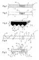
- the optical structure 1comprises on each of the faces 2 and 3 at least one microrelief network 5 extending over a portion 4 only of the corresponding face 2 or 3, as shown in FIG. figure 5 .
- the structure 1has a first interface 11, respectively a second interface 12, formed by the microrelief array or networks 5 of the first face 2, respectively the second face 3, as illustrated in FIG. figure 5 .
- Each network 5comprises in the example in question microreliefs 6 represented in FIG. figure 3 , in the form of a triangular prism each having dimensions, in cross section, greater than the wavelengths of visible light, and possibly near-infrared radiation. These dimensions, in particular the thickness e of the microreliefs, may for example be greater than 1 ⁇ m, especially 1.2 ⁇ m.
- the distance d between the vertices of two adjacent prismsmay be between 100 microns and 900 microns, being for example close to 350 microns.
- the thickness e of a prismcan be for example between 50 microns and 300 microns, for example being close to 170 microns.
- the maximum thickness E of the optical structure 1may be between 100 ⁇ m and 900 ⁇ m, being for example close to 500 ⁇ m.
- the angle ⁇ between a local normal X to the optical structure 1 and a face of a microrelief 6may be between 30 ° and 60 °, being for example close to 45 °.
- microreliefs 6are advantageously chosen as a function of the refractive index of the material or materials used in the structure 1.
- microreliefs 6form parallel striations in the example under consideration.
- the microrelief network 5may for example be similar to that present on the film marketed by the American company 3M under the name Scotch TM Optical Lighting Film.
- the structure 1is preferably flexible, for example being able to be foldable.
- the microreliefs 6are made of a material 15 having a refractive index greater than that of air, this material may be for example a transparent polymer such as polyester or PMMA.
- the microreliefs 6can be obtained for example by etching, mechanical or chemical.
- microreliefs 6can be obtained by printing an ink or by embossing.
- a first medium of refractive index n 1(formed by the ambient air) is passed to a second medium (formed by the material 15) of refractive index n 2 higher than n 1 .
- Each array of microreliefs 5 on the face 2, respectively on the face 3,is superimposed exactly on a substantially smooth zone 8 of the other face.
- angles at 0 , a 1 , and a 2can for example be substantially equal to 0 °, 45 ° and 90 ° respectively.
- angles at 3 , 4 and 5may for example be substantially equal to 0 °, 45 ° and 90 °, respectively.
- the at least one microrelief network 5may define, in positive or in negative, at least one pattern 10 formed for example by a text, a symbol, a logo and / or a drawing.
- the pattern 10may appear substantially transparently surrounded by a substantially reflective zone, as illustrated in FIG. figure 1 .
- the pattern 10may appear with a substantially reflective appearance surrounded by a substantially transparent area as shown in FIG. figure 2 .
- the structure 1may comprise, where appropriate, a succession of patterns 10 repeating regularly in one direction.
- the network of microreliefs 5may be arranged to restore a reflective metal appearance depending on the viewing angle.
- the material on which the microrelief arrays 5 are formedmay be based on a transparent polymer.
- the structure 1extends from a first edge 23 of the sheet material 21 to a second edge 24 opposite to the first.
- the sheet material 21may comprise one or more windows 22 leaving the optical structure 1 unobstructed.
- the window or windowsmay be made for example by means of reliefs present on a rotating roll cylinder of a paper machine used to manufacture the sheet material, as described for example in patent applications. EP 0 860 298 and EP 0 625 431 .
- Document 20may alternatively be one of the following: an identity document, a passport sheet or cover, a visa, a coupon, a valuable document other than a banknote, for example a check or a credit card, a label of protection and / or authentication, a label of traceability.
- the optical structure 1may comprise, in addition to the microrelief network or networks 5, at least one authentication and / or identification element chosen from at least one of the following elements: a highlighting element of a falsification, in particular visible and / or detectable by means of a specific detection device, an element with variable, interferential and / or diffractive, iridescent or liquid crystal optical effect, a magnetic coating, tracers detectable by X-ray fluorescence, biomarkers, a varnish or an ink, luminescent, fluorescent or phosphorescent tracers, photochromic, thermochromic, electroluminescent and / or piezochromic compounds and / or which change color in contact with one or more predetermined products.
- a highlighting element of a falsificationin particular visible and / or detectable by means of a specific detection device
- an element with variable, interferential and / or diffractive, iridescent or liquid crystal optical effecta magnetic coating
- tracersdetectable by X-ray fluor
- the optical structure 1may comprise a monolithic support 29 based on the material 15, on the faces 2 and 3 of which the micro-relief arrays 5 are formed, as illustrated in FIG. figure 5 .
- the optical structure 1may comprise a monolithic support 30 such as a film, having a first completely smooth face 31 and, on a second face 32 opposite the first face 31, portions 4 covered by one or more networks 5 of separated microreliefs by zones 8 substantially smooth.
- a monolithic support 30such as a film, having a first completely smooth face 31 and, on a second face 32 opposite the first face 31, portions 4 covered by one or more networks 5 of separated microreliefs by zones 8 substantially smooth.
- the structure 1further comprises at least one element 33 of smaller area than the support 30 and fixed.
Landscapes
- General Physics & Mathematics (AREA)
- Business, Economics & Management (AREA)
- Finance (AREA)
- Engineering & Computer Science (AREA)
- Computer Security & Cryptography (AREA)
- Physics & Mathematics (AREA)
- Accounting & Taxation (AREA)
- Credit Cards Or The Like (AREA)
- Laminated Bodies (AREA)
- Inspection Of Paper Currency And Valuable Securities (AREA)
- Photoreceptors In Electrophotography (AREA)
- Diaphragms For Electromechanical Transducers (AREA)
- Optical Filters (AREA)
- Inks, Pencil-Leads, Or Crayons (AREA)
- Facsimile Heads (AREA)
Abstract
Description
Translated fromFrenchLa présente invention concerne une structure optique, notamment pour un document de sécurité et/ou de valeur.The present invention relates to an optical structure, in particular for a security document and / or value.
On connaît par la demande internationale
Le brevet
On connaît par la demande internationale
On connaît encore par la demande internationale
Le brevet
L'invention vise à proposer une structure optique, notamment pour un document de sécurité et/ou de valeur, permettant de créer de nouveaux effets optiques en vue notamment de renforcer la sécurité du document contre une éventuelle tentative de contrefaçon.The invention aims to provide an optical structure, particularly for a security document and / or value, to create new optical effects in particular to enhance the security of the document against a possible attempt to counterfeit.
L'invention a ainsi pour objet, selon l'un de ses aspects, une structure optique selon la revendication 1.The invention thus has, according to one of its aspects, an optical structure according to
Les interfaces peuvent par exemple générer des effets optiques, éventuellement variables selon l'angle d'observation, qui sont différents d'une interface à l'autre.The interfaces may for example generate optical effects, possibly variable depending on the angle of observation, which are different from one interface to another.
L'invention permet ainsi de créer, en lumière visible et/ou infrarouge et/ou ultraviolette, de nouveaux effets visuels afin par exemple d'améliorer l'esthétique d'un document et/ou la sécurité de celui-ci contre une tentative de contrefaçon.The invention thus makes it possible to create, in visible and / or infrared and / or ultraviolet light, new visual effects in order, for example, to improve the aesthetics of a document and / or the security thereof against an attempt to infringement.
Les interfaces peuvent, le cas échéant, être entièrement décalées l'une par rapport à l'autre, c'est-à-dire sans portions se superposant.The interfaces may, if necessary, be entirely offset relative to each other, that is to say without overlapping portions.
Lorsque l'une au moins des interfaces présente un contour définissant un motif, en positif ou en négatif, ce motif peut présenter un aspect visuel différent de l'aspect visuel d'une zone l'entourant.When at least one of the interfaces has a contour defining a pattern, positive or negative, this pattern may have a different visual appearance of the visual appearance of an area surrounding it.
Le motif peut comporter par exemple un caractère alphanumérique, un symbole, un logo ou un dessin.The pattern may comprise for example an alphanumeric character, a symbol, a logo or a drawing.
Dans un exemple de mise en oeuvre de l'invention, l'un au moins des réseaux de microreliefs se superpose au moins partiellement, notamment exactement, à une zone sensiblement lisse, dépourvue de microrelief, de l'une des faces extérieures.In an exemplary implementation of the invention, at least one of the microrelief arrays is superimposed at least partially, in particular exactly, on a substantially smooth zone, devoid of microrelief, of one of the outer faces.
L'une au moins des interfaces peut être formée par exemple sur l'une des faces extérieures de la structure.At least one of the interfaces may be formed for example on one of the outer faces of the structure.
L'un au moins des premier et quatrième milieux peut être formé par l'air ambiant.At least one of the first and fourth media may be formed by the ambient air.
Les deuxième et troisième milieux peuvent être formés par exemple par un même matériau et avoir le même indice de réfraction, notamment un matériau ayant un indice de réfraction supérieur à 1, notamment 1,5, par exemple 2.The second and third media may be formed for example by the same material and have the same refractive index, especially a material having a refractive index greater than 1, especially 1.5, for example 2.
En variante, les deuxième et troisième milieux peuvent être formés par des matériaux différents et/ou ayant des indices de réfraction différents.Alternatively, the second and third media may be formed by different materials and / or having different refractive indices.
Le premier milieu peut être formé par exemple par un premier matériau sur lequel est réalisé le premier réseau de microreliefs et le deuxième milieu par un deuxième matériau déposé, notamment par dépôt sous vide, sur le premier matériau.The first medium may be formed for example by a first material on which the first micro-relief array is made and the second medium by a second deposited material, in particular by vacuum deposition, on the first material.
Le deuxième matériau peut recouvrir partiellement ou entièrement le premier matériau et former, si on le souhaite, au moins un motif. Le deuxième matériau peut former, le cas échéant, une protection extérieure de la structure optique et présenter un indice de réfraction par exemple supérieur à 1,8.The second material may partially or wholly cover the first material and form, if desired, at least one pattern. The second material may form, if necessary, an outer protection of the optical structure and have a refractive index, for example greater than 1.8.
Le deuxième matériau peut être obtenu par exemple par vaporisation, par exemple de sulfure de zinc ayant un indice de réfraction d'environ 2,3.The second material can be obtained for example by vaporization, for example zinc sulphide having a refractive index of about 2.3.
De préférence, la différence entre le deuxième indice de réfraction et le premier indice de réfraction est supérieure à 0,1, de préférence encore à 0,15, de préférence à 0,2 ou 0,3 ou 0,4. De préférence, cette différence est comprise entre 0,4 et 0,6.Preferably, the difference between the second refractive index and the first refractive index is greater than 0.1, more preferably 0.15, preferably 0.2 or 0.3 or 0.4. Preferably, this difference is between 0.4 and 0.6.
De préférence, la différence entre le troisième indice de réfraction et le quatrième indice de réfraction est supérieure à 0,1, de préférence encore à 0,15, de préférence à 0,2 ou 0,3 ou 0,4. De préférence, cette différence est comprise entre 0,4 et 0,6.Preferably, the difference between the third refractive index and the fourth refractive index is greater than 0.1, more preferably 0.15, preferably 0.2 or 0.3 or 0.4. Preferably, this difference is between 0.4 and 0.6.
L'une au moins des interfaces est agencée de manière à ce que, pour au moins une première plage d'angles d'observation, une portion de la structure au droit de cette interface apparaisse sensiblement transparente lorsque la structure est observée depuis l'une des première et deuxième faces extérieures, notamment en lumière visible et/ou infrarouge et/ou ultraviolette.At least one of the interfaces is arranged so that, for at least a first range of observation angles, a portion of the structure at the right of this interface appears substantially transparent when the structure is observed from the one first and second outer faces, especially in visible light and / or infrared and / or ultraviolet.
L'une au moins des interfaces est agencée de manière à ce que, pour au moins une deuxième plage d'angles d'observation, une portion de la structure au droit de cette interface apparaisse sensiblement réfléchissante lorsque la structure est observée depuis une face extérieure, notamment en lumière visible et/ou infrarouge et/ou ultraviolette.At least one of the interfaces is arranged so that, for at least a second range of observation angles, a portion of the structure at the right of this interface appears substantially reflective when the structure is observed from an outside face , especially in visible light and / or infrared and / or ultraviolet.
Avantageusement, l'une au moins des interfaces est agencée de manière à ce que, pour une première plage d'angles d'observation, une portion de la structure au droit de cette interface apparaisse sensiblement transparente lorsque la structure est observée depuis une face extérieure prédéterminée et, pour une deuxième plage d'angles d'observation, cette portion de la structure apparaisse sensiblement réfléchissante lorsque la structure est observée depuis ladite face extérieure.Advantageously, at least one of the interfaces is arranged in such a way that, for a first range of observation angles, a portion of the structure at the right of this interface appears substantially transparent when the structure is observed from an outside face. predetermined, and for a second range of observation angles, this portion of the structure appears substantially reflective when the structure is observed from said outer face.
Ainsi, lorsque la ou les interfaces présentent un contour définissant un motif, celui-ci peut apparaître, en lumière visible, avec un aspect réfléchissant ou transparent selon l'angle d'observation de la structure.Thus, when the interface or interfaces have a contour defining a pattern, it may appear, in visible light, with a reflective or transparent appearance depending on the viewing angle of the structure.
L'invention peut, le cas échéant, permettre, en faisant varier l'angle d'observation, d'apercevoir le motif successivement en positif, avec un aspect réfléchissant et entouré d'une zone transparente et, en négatif, avec un aspect transparent, entouré d'une zone réfléchissante.The invention can, if necessary, allow, by varying the angle of observation, to see the pattern successively positive, with a reflective appearance and surrounded by a transparent zone and, in negative, with a transparent appearance surrounded by a reflective area.
Dans un exemple de mise en oeuvre de l'invention, l'un au moins des microreliefs présente sensiblement une forme en prisme triangulaire.In an exemplary implementation of the invention, at least one of the microreliefs has substantially a triangular prism shape.
Le réseau de microreliefs peut être agencé par exemple de manière à restituer un aspect métallisé, notamment réfléchissant, lorsque la structure optique est observée suivant une plage d'angles prédéterminée.The network of microreliefs may be arranged for example so as to restore a metallized appearance, especially reflecting, when the optical structure is observed in a predetermined range of angles.
Le ou les réseaux de microreliefs peuvent par exemple être analogues à celui présent sur le film commercialisé par la société 3M sous la dénomination Scotch™ Optical Lighting Film.For example, the microrelief array (s) may be similar to that present on the film marketed by 3M under the name Scotch ™ Optical Lighting Film.
Dans un autre exemple de mise en oeuvre de l'invention, l'un au moins des microreliefs comporte au moins une surface courbe, concave ou convexe, chaque surface courbe pouvant créer un effet de lentille.In another exemplary embodiment of the invention, at least one of the microreliefs comprises at least one curved, concave or convex surface, each curved surface being able to create a lens effect.
La surface courbe peut par exemple être une surface demi-cylindrique ou en calotte sphérique, notamment demi-sphérique, cette liste n'étant pas limitative.The curved surface may for example be a half-cylindrical surface or spherical cap, in particular half-spherical, this list not being limiting.
Les microreliefs peuvent présenter une épaisseur par exemple supérieure à 1 µm.The microreliefs may have a thickness, for example, greater than 1 μm.
L'épaisseur des microreliefs est de préférence inférieure à 10 mm, notamment 1 mm.The thickness of the microreliefs is preferably less than 10 mm, especially 1 mm.
Dans un exemple de mise en oeuvre de l'invention, une partie au moins des microreliefs s'étend suivant une direction longitudinale, les microreliefs étant sensiblement parallèles les uns aux autres.In an exemplary implementation of the invention, at least a portion of the microreliefs extends in a longitudinal direction, the microreliefs being substantially parallel to each other.
Les microreliefs respectivement des premier et deuxième réseaux peuvent être identiques ou, en variante, différents, par exemple ayant des formes et/ou des dimensions différentes.The microreliefs respectively of the first and second networks may be identical or, alternatively, different, for example having different shapes and / or dimensions.
Les microreliefs des premier et deuxième réseaux peuvent être réalisés sur un support commun, sur une même face de ce support ou sur deux faces opposées de celui-ci.The microreliefs of the first and second networks can be made on a common support, on the same face of this support or on two opposite faces thereof.
La structure optique peut comporter par exemple un support avec sur une face au moins un réseau de microreliefs, le réseau de microreliefs étant recouvert partiellement d'une couche de revêtement ayant un indice de réfraction plus élevé que celui du support de manière à ce que la première interface soit formée entre le support et l'air ambiant et la deuxième interface entre le support et la couche de revêtement, les première et deuxième interfaces étant notamment adjacentes. La couche de revêtement peut comporter par exemple du sulfure de zinc.The optical structure may comprise, for example, a support with at least one micro-relief array on one side, the microrelief network being partially covered with a coating layer having a refractive index higher than that of the support, so that the first interface is formed between the support and the ambient air and the second interface between the support and the coating layer, the first and second interfaces being in particular adjacent. The coating layer may comprise, for example, zinc sulphide.
La structure optique selon l'invention peut ainsi être réalisée de manière relativement aisée du fait qu'un unique ensemble de microreliefs peut servir pour former les deux interfaces.The optical structure according to the invention can thus be made relatively easily because a single set of microreliefs can be used to form the two interfaces.
Dans un autre exemple de mise en oeuvre de l'invention, les premier et deuxième réseaux de microreliefs peuvent être réalisés sur des supports distincts.In another exemplary embodiment of the invention, the first and second microrelief networks may be made on separate supports.
La structure peut comporter, si on le souhaite, au moins un matériau électriquement conducteur.The structure may comprise, if desired, at least one electrically conductive material.
L'authentification et/ou l'identification de la structure peut ainsi être basée sur une mesure de la conductivité électrique de celle-ci, en plus de son observation visuelle.The authentication and / or the identification of the structure can thus be based on a measurement of the electrical conductivity of the latter, in addition to its visual observation.
Dans un exemple de mise en oeuvre de l'invention, la structure comporte au moins un support sur lequel est réalisée une partie au moins des microreliefs, le support étant notamment réalisé en un matériau polymère sensiblement transparent, tel que le polyester ou le PMMA (polyméthacrylate de méthyle).In an exemplary implementation of the invention, the structure comprises at least one support on which at least a portion of the microreliefs is made, the support being in particular made of a substantially transparent polymer material, such as polyester or PMMA ( polymethylmethacrylate).
Le support peut comporter une couche électriquement conductrice, par exemple à base d'un polymère conducteur tel que le polythiophène ou ses dérivés ou à base d'un composite d'oxyde d'indium étain.The support may comprise an electrically conductive layer, for example based on a polymer conductor such as polythiophene or its derivatives or based on a composite of indium tin oxide.
La structure peut être dépourvue de métal, notamment d'une couche métallisée.The structure may be devoid of metal, in particular a metallized layer.
Le cas échéant, la structure peut être agencée pour pouvoir être transférée au moins partiellement sur une face d'un document, la structure pouvant comporter au moins une couche d'adhésif.Where appropriate, the structure may be arranged to be able to be transferred at least partially to a face of a document, the structure may comprise at least one layer of adhesive.
La structure peut comporter, en plus du réseau de microreliefs, au moins un élément d'authentification et/ou d'identification choisi parmi au moins l'un des éléments suivants : un élément de mise en évidence d'une falsification, notamment visible et/ou détectable à l'aide d'un dispositif spécifique de détection, un élément à effet optique variable, interférentiel et/ou diffractif, iridescent ou à cristaux liquides, un revêtement magnétique, des traceurs détectables par fluorescence X, des biomarqueurs, un vernis ou une encre, des traceurs luminescents, fluorescents ou phosphorescents, des composés photochromiques, thermochromiques, électroluminescents et/ou piézochromiques et/ou qui changent de couleur au contact d'un ou de plusieurs produits prédéterminés.The structure may comprise, in addition to the microrelief network, at least one authentication and / or identification element chosen from at least one of the following elements: an element for highlighting a falsification, in particular visible and or detectable with the aid of a specific detection device, an element with variable optical effect, interferential and / or diffractive, iridescent or liquid crystal, a magnetic coating, tracers detectable by X-ray fluorescence, biomarkers, a varnish or an ink, luminescent, fluorescent or phosphorescent tracers, photochromic, thermochromic, electroluminescent and / or piezochromic compounds and / or which change color in contact with one or more predetermined products.
La structure peut comporter, le cas échéant, au moins un matériau fluorescent sous rayonnement infrarouge et/ou ultraviolet, déposé par exemple sous la forme d'une couche, notamment sur l'une des faces de la structure.The structure may comprise, where appropriate, at least one fluorescent material under infrared and / or ultraviolet radiation, deposited for example in the form of a layer, in particular on one of the faces of the structure.
L'invention peut ainsi permettre d'observer, en lumière visible, sous excitations en rayonnement infrarouge et/ou ultraviolet, une couche fluorescente sous-jacente, à travers la portion de la structure apparaissant transparente pour la première plage d'angles d'observation.The invention can thus make it possible to observe, in visible light, under infrared and / or ultraviolet radiation excitations, an underlying fluorescent layer, through the portion of the structure appearing transparent for the first range of observation angles. .
Pour la deuxième plage d'angles d'observation, la portion précitée de la structure, étant réfléchissante, ne permet pas l'observation de la fluorescence de la couche sous-jacente.For the second range of observation angles, the aforementioned portion of the structure, being reflective, does not allow the observation of the fluorescence of the underlying layer.
Dans un exemple de mise en oeuvre de l'invention, la structure est agencée de manière à ce que, lorsqu'elle est observée sous un angle et depuis une face prédéterminés, la structure présente à la fois au moins une zone sensiblement transparente et au moins une zone sensiblement réfléchissante.In an exemplary implementation of the invention, the structure is arranged so that, when viewed at a predetermined angle and from a predetermined face, the structure has both at least one substantially transparent zone and at least one less a substantially reflective zone.
L'invention a encore pour objet, selon un autre de ses aspects, un matériau en feuille comprenant une structure optique telle que définie ci-dessus.The invention further relates, in another of its aspects, a sheet material comprising an optical structure as defined above.
L'expression « matériau en feuille » peut désigner dans la description et les revendications une feuille fibreuse à base de fibres cellulosiques et/ou synthétiques, présentant une structure monocouche ou multicouche, composite ou non. Un matériau en feuille peut par exemple présenter une épaisseur relativement faible, notamment inférieure ou égale à 3 mm, par exemple égale à 100 µm environ, et être flexible. Dans un exemple de mise en oeuvre de l'invention, le matériau en feuille peut être conditionné en bobine, notamment avant d'être découpé au format souhaité. L'expression « matériau en feuille » peut également désigner un film souple ou rigide, à structure monolithique ou multicouche.The term "sheet material" may denote in the description and the claims a fibrous sheet based on cellulosic and / or synthetic fibers, having a monolayer or multilayer structure, composite or not. A sheet material may for example have a relatively small thickness, especially less than or equal to 3 mm, for example equal to about 100 microns, and be flexible. In an exemplary implementation of the invention, the sheet material may be packaged in a reel, in particular before being cut into the desired format. The expression "sheet material" can also denote a flexible or rigid film with a monolithic or multilayer structure.
La structure optique comporte avantageusement au moins une portion apparente sur une face du matériau en feuille.The optical structure advantageously comprises at least one apparent portion on one side of the sheet material.
La structure optique peut être partiellement noyée dans la masse du matériau en feuille, celui-ci comportant notamment au moins une fenêtre laissant dégagée la structure optique.The optical structure may be partially embedded in the mass of the sheet material, the latter including in particular at least one window leaving the optical structure unobstructed.
Lorsque la structure optique présente une forme en bande, celle-ci peut s'étendre d'un premier bord du matériau en feuille à un deuxième bord, opposé au premier.When the optical structure has a strip shape, it may extend from a first edge of the sheet material to a second edge opposite the first.
En variante, la structure optique est disposée sur une face du matériau en feuille, en étant par exemple collée sur cette face.Alternatively, the optical structure is disposed on one side of the sheet material, for example being glued to this face.
Dans un exemple de mise en oeuvre de l'invention, le matériau en feuille comporte au moins un élément d'information tel qu'un caractère alphanumérique, un symbole, un logo ou un dessin, la structure optique étant agencée de manière à pouvoir masquer sensiblement l'élément d'information lorsque cette structure est observée suivant une première plage d'angles et présente un aspect réfléchissant.In an exemplary implementation of the invention, the sheet material comprises at least one piece of information such as an alphanumeric character, a symbol, a logo or a drawing, the optical structure being arranged so as to be able to mask substantially the information element when this structure is observed in a first range of angles and has a reflective appearance.
Le matériau en feuille peut comporter au moins une couche fibreuse ou, en variante, une matière plastique.The sheet material may comprise at least one fibrous layer or, alternatively, a plastics material.
Selon le cas, l'une au moins des première et deuxième faces extérieures de la structure optique peut être au contact de l'air ambiant ou de la matière fibreuse du matériau en feuille.Depending on the case, at least one of the first and second outer faces of the optical structure may be in contact with the ambient air or the fibrous material of the sheet material.
L'invention a encore pour objet, selon un autre de ses aspects, un document de sécurité et/ou de valeur comportant un matériau en feuille tel que défini ci-dessus.The invention further relates, in another of its aspects, a security document and / or value comprising a sheet material as defined above.
Le document peut constituer l'un des éléments suivants : un billet de banque, un document d'identité, une feuille ou une couverture de passeport, un visa, un coupon, un document de valeur autre qu'un billet de banque, par exemple un chèque ou une carte de crédit, une étiquette de protection et/ou d'authentification, une étiquette de traçabilité.The document may be one of the following: a bank note, an identity document, a passport sheet or cover, a visa, a coupon, a document of value other than a bank note, for example a check or a credit card, a label of protection and / or authentication, a label of traceability.
L'invention pourra être mieux comprise à la lecture de la description détaillée qui va suivre, d'exemples de mise en oeuvre non limitatifs de l'invention, et à l'examen du dessin annexé, sur lequel :
- les
figures 1 représentent, schématiquement et partiellement, une structure optique conforme à l'invention, observée respectivement suivant deux angles différents,et 2 - la
figure 3 illustre, schématiquement et partiellement, un réseau de microreliefs de la structure optique desfigures 1 ,et 2 - la
figure 4 illustre très schématiquement le tràjet de faisceaux lumineux dans la structure de lafigure 3 , - la
figure 5 représente, schématiquement et partiellement, en coupe, la structure optique de lafigure 1 , - la
figure 6 représente, schématiquement et partiellement, un document conforme à des exemples de l'invention, - les
figures 9 à 16 représentent, schématiquement et partiellement, en coupe, différents exemples de structures optiques conformes à l'invention.
- the
Figures 1 and 2 represent, schematically and partially, an optical structure according to the invention, respectively observed at two different angles, - the
figure 3 illustrates, schematically and partially, a network of microreliefs of the optical structure ofFigures 1 and 2 , - the
figure 4 very schematically illustrates the beam of light beams in the structure of thefigure 3 , - the
figure 5 represents, schematically and partially, in section, the optical structure of thefigure 1 , - the
figure 6 represents, schematically and partially, a document according to examples of the invention, - the
Figures 9 to 16 show, schematically and partially, in section, various examples of optical structures according to the invention.
Sur le dessin, dans un souci de clarté, les proportions relatives des différents éléments représentés n'ont pas toujours été respectées, les vues étant schématiques.In the drawing, for the sake of clarity, the relative proportions of the various elements represented have not always been respected, the views being schematic.
On a représenté sur les
La structure optique 1 comporte sur chacune des faces 2 et 3 au moins un réseau de microreliefs 5 s'étendant sur une portion 4 seulement de la face 2 ou 3 correspondante, comme illustré sur la
La structure 1 présente une première interface 11, respectivement une deuxième interface 12, formée par le ou les réseaux 5 de microreliefs de la première face 2, respectivement la deuxième face 3, comme illustré sur la
Chaque réseau 5 comporte dans l'exemple considéré des microreliefs 6 représentés à la
Par exemple, la distanced entre les sommets de deux prismes adjacents peut être comprise entre 100 µm et 900 µm, étant par exemple voisine de 350 µm.For example, the distanced between the vertices of two adjacent prisms may be between 100 microns and 900 microns, being for example close to 350 microns.
L'épaisseur e d'un prisme peut être comprise par exemple entre 50 µm et 300 µm, étant par exemple voisine de 170 µm.The thickness e of a prism can be for example between 50 microns and 300 microns, for example being close to 170 microns.
L'épaisseur maximale E de la structure optique 1 peut être comprise entre 100 µm et 900 µm, étant par exemple voisine de 500 µm.The maximum thickness E of the
Comme illustré sur la
Les dimensions et les angles des microreliefs 6 sont avantageusement choisis en fonction de l'indice de réfraction du ou des matériaux utilisés dans la structure 1.The dimensions and the angles of the
Les microreliefs 6 forment des stries parallèles dans l'exemple considéré.The
Le réseau de microreliefs 5 peut par exemple être analogue à celui présent sur le film commercialisé par la société américaine 3M sous la dénomination Scotch™ Optical Lighting Film.The
La structure 1 est de préférence flexible, pouvant par exemple être pliable.The
Les microreliefs 6 sont réalisés sur un matériau 15 ayant un indice de réfraction supérieur à celui de l'air, ce matériau pouvant être par exemple un polymère transparent tel que le polyester ou le PMMA.The
Les microreliefs 6 peuvent être obtenus par exemple par gravure, mécanique ou chimique.The
En variante, les microreliefs 6 peuvent être obtenus par impression d'une encre ou par embossage.Alternatively, the
Lorsque l'on traverse la première interface 11 dans le sens de la première face 2 vers la deuxième face 3, on passe d'un premier milieu d'indice de réfraction n1 (formé par l'air ambiant) à un deuxième milieu (formé par le matériau 15) d'indice de réfraction n2 plus élevé que n1.When crossing the
Lorsque l'on traverse la deuxième interface 12 dans le sens de la première face 2 vers la deuxième face 3, on passe d'un troisième milieu d'indice n3 (formé par le matériau 15, avec n3 = n2) à un quatrième milieu (formé par l'air ambiant) d'indice de réfraction n4 plus faible. On a donc n4 = n1.When crossing the
Chaque réseau de microreliefs 5 sur la face 2, respectivement sur la face 3, se superpose exactement à une zone sensiblement lisse 8 de l'autre face.Each array of
Comme illustré sur la
Un faisceau lumineux B pénétrant dans la structure optique, au niveau de la portion 4, avec un angle compris dans l'intervalle ]a0 ; a1] par rapport à la normale X, ressort par la face 2 opposée de sorte que la portion de la structure 1 au droit du réseau 5 apparaisse avec un aspect transparent.A light beam B entering the optical structure, at the
Les angles a0, a1, et a2 peuvent par exemple être sensiblement égaux à respectivement 0°, 45° et 90°.The angles at0 , a1 , and a2 can for example be substantially equal to 0 °, 45 ° and 90 ° respectively.
Un faisceau lumineux C pénétrant dans la structure optique 1, au niveau d'une zone 8 sensiblement lisse de la première face 2, avec un angle compris dans l'intervalle [a3 ; a4] par rapport à la normale X, est réfléchi par le réseau de microreliefs 5 sur la face opposée 3 de sorte que la portion de la structure au droit du réseau 5 apparaisse avec un aspect sensiblement réfléchissant.A light beam C entering the
Un faisceau lumineux D pénétrant dans la structure_optique 1 par la zone 8 avec un angle compris dans l'intervalle [a4 ; a5] par rapport à la normale X, ressort par la face opposée 3 de sorte que la portion de la structure 1 au droit du réseau 5 apparaisse avec un aspect sensiblement transparent.A light beam D entering the
Les angles a3, a4 et a5 peuvent par exemple être sensiblement égaux à respectivement 0°, 45° et 90°.The angles at3 ,4 and5 may for example be substantially equal to 0 °, 45 ° and 90 °, respectively.
Le ou les réseaux de microreliefs 5 peuvent définir, en positif ou en négatif, au moins un motif 10 formé par exemple par un texte, un symbole, un logo et/ou un dessin.The at least one
Lorsque la structure optique 1 est observée depuis la face 2 suivant une première plage d'angles, correspondant par exemple à l'intervalle [a4 ; a5], le motif 10 peut apparaître de manière sensiblement transparente entouré d'une zone sensiblement réfléchissante, comme illustré sur la
Lorsque la structure 1 est observée depuis la face 2 suivant une deuxième plage d'angles, correspondant par exemple à l'intervalle [a3 ; a4], le motif 10 peut apparaître avec un aspect sensiblement réfléchissant entouré d'une zone sensiblement transparente, comme illustré sur la
La structure 1 peut comporter, le cas échéant, une succession de motifs 10 se répétant de manière régulière suivant une direction.The
Le réseau de microreliefs 5 peut être agencé de manière à restituer un aspect métallique réfléchissant en fonction de l'angle d'observation.The network of
Le matériau 15 sur lequel sont formés les réseaux de microreliefs 5 peut être à base d'un polymère transparent.The material on which the
On a représenté sur la
La structure 1 s'étend d'un premier bord 23 du matériau en feuille 21 à un deuxième bord 24 opposé au premier.The
Le matériau en feuille 21 peut comporter une ou plusieurs fenêtres 22 laissant dégagée la structure optique 1.The
La ou les fenêtres peuvent être réalisées par exemple à l'aide de reliefs présents sur un cylindre de toile rotatif d'une machine à papier servant à fabriquer le matériau en feuille, comme cela est décrit par exemple dans les demandes de brevet
Le document 20 peut constituer, en variante, l'un des éléments suivants : un document d'identité, une feuille ou une couverture de passeport, un visa, un coupon, un document de valeur autre qu'un billet de banque, par exemple un chèque ou une carte de crédit, une étiquette de protection et/ou d'authentification, une étiquette de traçabilité.
La structure optique 1 peut comporter, en plus du ou des réseaux de microreliefs 5, au moins un élément d'authentification et/ou d'identification choisi parmi au moins l'un des éléments suivants : un élément de mise en évidence d'une falsification, notamment visible et/ou détectable à l'aide d'un dispositif spécifique de détection, un élément à effet optique variable, interférentiel et/ou diffractif, iridescent ou à cristaux liquides, un revêtement magnétique, des traceurs détectables par fluorescence X, des biomarqueurs, un vernis ou une encre, des traceurs luminescents, fluorescents ou phosphorescents, des composés photochromiques, thermochromiques, électroluminescents et/ou piézochromiques et/ou qui changent de couleur au contact d'un ou de plusieurs produits prédéterminés.The
La structure optique 1 peut comporter un support monolithique 29 à base du matériau 15, sur les faces 2 et 3 duquel sont formés les réseaux de microreliefs 5, comme illustré sur la
En variante, comme illustré sur la
La structure 1 comporte en outre au moins un élément 33 de superficie plus faible que le support 30 et fixé.The
Claims (11)
- Optical structure, especially for a security document and/or a document of value, comprising:- opposed first and second outer faces (2, 3)- at least one first interface ( 11), comprising a first network of microreliefs (5), and arranged in such a way that, when there is crossing of this first interface in the direction from the first outer face towards the second outer face, there is passing from a first medium having a first refraction index (n1) to a second medium having a second refraction index (n2), which is greater than the first;- at least one second interface (12) comprising a second network of microreliefs (5) and arranged in such a way that, when there is crossing of this second interface in the direction from the first outer face towards the second outer face, there is passing from a third medium having a third refraction index (n3) to a fourth medium having a fourth refraction index (fl4), which is less than the third;
each interface having at least one portion offset in relation to the other interface when the structure is observed following a direction (x) approximately perpendicular to at least one of the outer faces, the optical structure having a form of a band with a width comprised between 2 mm and 45 mm, in which at least one of the interfaces is arranged in such a way that, for a first range of observation angles, a portion of the structure to the right of this interface appears essentially transparent when the structure is observed from a predetermined outer face, and, for a second range of observation angles, this portion of the structure appears essentially reflective when the structure is observed from an outer face and, in which the microreliefs have a thickness greater than the wavelengths of visible light, in particular from radiation close to infrared, in particular greater than 1 µm. - Structure according to the preceding Claim, in which the interfaces are entirely offset in relation to one another when the structure is observed following said direction approximately perpendicular to at least one of the outer faces.
- Structure according to any one of the preceding Claims, in which at least one of the networks of microreliefs is superimposed at least partially, in particular exactly, in an area approximately flush with one of the outer faces.
- Structure according to any one of the preceding Claims, in which at least one of the interfaces is formed on at least one of the outer faces of the structure.
- Structure according to any one of Claims 1 to 4, in which the second and third media are formed by different materials and/or having different refraction indices.
- Structure according to any one of the preceding Claims, in which the first medium is formed by a first material on which the first network of microreliefs is formed, and the second medium is formed by a second material deposited, in particular by vacuum deposition, on the first material.
- Structure according to any one of the preceding Claims, in which at least one of the microreliefs presents essentially the shape of a triangular prism.
- Structure according to the preceding Claim, in which the network of microreliefs is arranged in such a way as to create a metallised appearance, in particular reflective, when the optical structure is observed following a prearranged range of angles.
- Structure according to any one of the preceding Claims, in which the difference between the second refraction index and the first refraction index and/or between the third refraction index and the fourth refraction index is greater than 0.1.
- Film material comprising an optical structure according to any of the preceding Claims.
- Material according to Claim 10, comprising at least one element of information, the optical structure being arranged in such a way as to be able essentially to mask the element of information when the optical structure is observed according to a first range of angles and has a reflective appearance.
Applications Claiming Priority (2)
| Application Number | Priority Date | Filing Date | Title |
|---|---|---|---|
| FR0553480AFR2893424B1 (en) | 2005-11-16 | 2005-11-16 | OPTICAL STRUCTURE, IN PARTICULAR FOR A DOCUMENT OF SECURITY AND / OR VALUE. |
| PCT/FR2006/051186WO2007057613A1 (en) | 2005-11-16 | 2006-11-16 | Optical structure, especially for a security document and/or a document of value |
Publications (3)
| Publication Number | Publication Date |
|---|---|
| EP1951528A1 EP1951528A1 (en) | 2008-08-06 |
| EP1951528B1 EP1951528B1 (en) | 2009-02-25 |
| EP1951528B2true EP1951528B2 (en) | 2015-06-24 |
Family
ID=36764044
Family Applications (1)
| Application Number | Title | Priority Date | Filing Date |
|---|---|---|---|
| EP06831348.5AActiveEP1951528B2 (en) | 2005-11-16 | 2006-11-16 | Optical structure, especially for a security document and/or a document of value |
Country Status (9)
| Country | Link |
|---|---|
| US (1) | US8439402B2 (en) |
| EP (1) | EP1951528B2 (en) |
| AT (1) | ATE423687T1 (en) |
| BR (1) | BRPI0618742A2 (en) |
| CA (1) | CA2629926A1 (en) |
| DE (1) | DE602006005395D1 (en) |
| ES (1) | ES2322874T5 (en) |
| FR (1) | FR2893424B1 (en) |
| WO (1) | WO2007057613A1 (en) |
Families Citing this family (14)
| Publication number | Priority date | Publication date | Assignee | Title |
|---|---|---|---|---|
| US8595964B2 (en)* | 2006-06-09 | 2013-12-03 | Ubright Optronics Corporation | Surface bearing patterned indicia having micro-structures and method of making the same |
| FR2893424B1 (en) | 2005-11-16 | 2008-01-25 | Arjowiggins Soc Par Actions Si | OPTICAL STRUCTURE, IN PARTICULAR FOR A DOCUMENT OF SECURITY AND / OR VALUE. |
| US7820009B2 (en)* | 2006-08-18 | 2010-10-26 | The Royal Institution For The Advancement Of Learning/Mcgill University | Cellulose composites comprising hydrophobic particles and their use in paper products |
| DE102009007779C5 (en)* | 2009-02-04 | 2017-07-27 | Bundesdruckerei Gmbh | A method for producing a visually perceptible without technical aids security feature, security feature for plastic-based value or security document and document with at least one such security feature |
| DE102009031386A1 (en)* | 2009-07-01 | 2011-01-05 | Giesecke & Devrient Gmbh | Security element and manufacturing method therefor |
| MTP4301B (en)* | 2010-03-25 | 2011-10-26 | Securency Int Pty Ltd | High refractive index coatings and their use in the protection of surface relief structures |
| GB2493369B (en) | 2011-08-02 | 2013-09-25 | Rue De Int Ltd | Improvements in security devices |
| FR2979735B1 (en)* | 2011-09-02 | 2014-05-23 | Arjowiggins Security | SECURITY STRUCTURE COMPRISING TRANSPARENT VARNISH AND ASSOCIATED METHOD |
| DE102011117044B4 (en)* | 2011-10-27 | 2019-05-29 | Bundesdruckerei Gmbh | security element |
| US8720776B2 (en) | 2011-11-10 | 2014-05-13 | Paul Llewellyn Greene | X-ray security system |
| US8834004B2 (en) | 2012-08-13 | 2014-09-16 | 3M Innovative Properties Company | Lighting devices with patterned printing of diffractive extraction features |
| DE102013203303B3 (en) | 2012-12-20 | 2014-06-05 | Bundesdruckerei Gmbh | Security feature for a value and / or security product, the security feature exhibiting value and / or security product and method for producing the security feature |
| WO2018213292A1 (en)* | 2017-05-15 | 2018-11-22 | Agira, Inc. | Light guide apparatus and fabrication method thereof |
| GB2566019B (en)* | 2017-08-29 | 2021-05-05 | De La Rue Int Ltd | A security device and method of making thereof |
Citations (16)
| Publication number | Priority date | Publication date | Assignee | Title |
|---|---|---|---|---|
| US4856857A (en)† | 1985-05-07 | 1989-08-15 | Dai Nippon Insatsu Kabushiki Kaisha | Transparent reflection-type |
| EP0328086A2 (en)† | 1988-02-12 | 1989-08-16 | American Bank Note Holographics, Inc. | Articles incorporating non-continuous holographs and methods of making them |
| US5492370A (en)† | 1991-03-22 | 1996-02-20 | De La Rue Holographics Ltd. | Decorative article |
| US5573639A (en)† | 1993-12-23 | 1996-11-12 | Giesecke & Devrient Gmbh | Antifalsification paper having a thread- or band-shaped security element |
| WO1998013211A1 (en)† | 1996-09-26 | 1998-04-02 | Reserve Bank Of Australia | Banknotes incorporating security devices |
| CH689680A5 (en)† | 1997-12-12 | 1999-08-13 | Electrowatt Tech Innovat Corp | Smart card with durably-protected security elements, e.g. holograms |
| US6199911B1 (en)† | 1997-04-03 | 2001-03-13 | De La Rue International Limited | Security element for security paper |
| EP1141480A1 (en)† | 1998-12-29 | 2001-10-10 | De La Rue International Limited | Improvements in making paper |
| JP2001315472A (en)† | 2000-05-02 | 2001-11-13 | Dainippon Printing Co Ltd | Information recording medium and card having light diffraction structure, and light diffraction structure |
| WO2003053713A1 (en)† | 2001-12-21 | 2003-07-03 | Giesecke & Devrient Gmbh | Security element for security papers and valuable documents |
| WO2003055692A1 (en)† | 2001-12-21 | 2003-07-10 | Durand Technology Limited | Improvements in or relating to security or authentication markings and the like |
| WO2003068525A1 (en)† | 2002-02-14 | 2003-08-21 | Giesecke & Devrient Gmbh | Security element and security document with one such security element |
| WO2003082598A2 (en)† | 2002-04-03 | 2003-10-09 | De La Rue International Limited | Optically variable security device |
| WO2006108607A2 (en)† | 2005-04-13 | 2006-10-19 | Ovd Kinegram Ag | Transfer film |
| WO2007051529A1 (en)† | 2005-11-03 | 2007-05-10 | Giesecke & Devrient Gmbh | Transparent security element and method for its production |
| EP1888349A2 (en)† | 2005-03-10 | 2008-02-20 | De La Rue International Limited | Article and security device based on customised microprism film |
Family Cites Families (8)
| Publication number | Priority date | Publication date | Assignee | Title |
|---|---|---|---|---|
| DE59204591D1 (en)* | 1991-10-14 | 1996-01-18 | Landis & Gyr Tech Innovat | Security element. |
| US5301981A (en) | 1992-07-09 | 1994-04-12 | Docusafe, Ltd. | Copy preventing device and method |
| DE59500254D1 (en)* | 1995-03-16 | 1997-06-26 | Landis & Gyr Tech Innovat | Optical information carrier |
| CH691750A5 (en)* | 1995-11-28 | 2001-09-28 | Ovd Kinegram Ag | Optical information carrier made of composite laminate with carrier foil |
| GB0016356D0 (en) | 2000-07-03 | 2000-08-23 | Optaglio Ltd | Optical structure |
| US7290802B1 (en)* | 2003-01-22 | 2007-11-06 | Serigraph, Inc. | Second surface micromotion display |
| CA2990275C (en)* | 2003-11-21 | 2023-01-03 | Visual Physics, Llc | Micro-optic security and image presentation system |
| FR2893424B1 (en) | 2005-11-16 | 2008-01-25 | Arjowiggins Soc Par Actions Si | OPTICAL STRUCTURE, IN PARTICULAR FOR A DOCUMENT OF SECURITY AND / OR VALUE. |
- 2005
- 2005-11-16FRFR0553480Apatent/FR2893424B1/ennot_activeExpired - Fee Related
- 2006
- 2006-11-16WOPCT/FR2006/051186patent/WO2007057613A1/enactiveApplication Filing
- 2006-11-16DEDE602006005395Tpatent/DE602006005395D1/enactiveActive
- 2006-11-16BRBRPI0618742-0Apatent/BRPI0618742A2/ennot_activeIP Right Cessation
- 2006-11-16USUS12/085,033patent/US8439402B2/ennot_activeExpired - Fee Related
- 2006-11-16CACA002629926Apatent/CA2629926A1/ennot_activeAbandoned
- 2006-11-16ESES06831348.5Tpatent/ES2322874T5/enactiveActive
- 2006-11-16EPEP06831348.5Apatent/EP1951528B2/enactiveActive
- 2006-11-16ATAT06831348Tpatent/ATE423687T1/ennot_activeIP Right Cessation
Patent Citations (16)
| Publication number | Priority date | Publication date | Assignee | Title |
|---|---|---|---|---|
| US4856857A (en)† | 1985-05-07 | 1989-08-15 | Dai Nippon Insatsu Kabushiki Kaisha | Transparent reflection-type |
| EP0328086A2 (en)† | 1988-02-12 | 1989-08-16 | American Bank Note Holographics, Inc. | Articles incorporating non-continuous holographs and methods of making them |
| US5492370A (en)† | 1991-03-22 | 1996-02-20 | De La Rue Holographics Ltd. | Decorative article |
| US5573639A (en)† | 1993-12-23 | 1996-11-12 | Giesecke & Devrient Gmbh | Antifalsification paper having a thread- or band-shaped security element |
| WO1998013211A1 (en)† | 1996-09-26 | 1998-04-02 | Reserve Bank Of Australia | Banknotes incorporating security devices |
| US6199911B1 (en)† | 1997-04-03 | 2001-03-13 | De La Rue International Limited | Security element for security paper |
| CH689680A5 (en)† | 1997-12-12 | 1999-08-13 | Electrowatt Tech Innovat Corp | Smart card with durably-protected security elements, e.g. holograms |
| EP1141480A1 (en)† | 1998-12-29 | 2001-10-10 | De La Rue International Limited | Improvements in making paper |
| JP2001315472A (en)† | 2000-05-02 | 2001-11-13 | Dainippon Printing Co Ltd | Information recording medium and card having light diffraction structure, and light diffraction structure |
| WO2003053713A1 (en)† | 2001-12-21 | 2003-07-03 | Giesecke & Devrient Gmbh | Security element for security papers and valuable documents |
| WO2003055692A1 (en)† | 2001-12-21 | 2003-07-10 | Durand Technology Limited | Improvements in or relating to security or authentication markings and the like |
| WO2003068525A1 (en)† | 2002-02-14 | 2003-08-21 | Giesecke & Devrient Gmbh | Security element and security document with one such security element |
| WO2003082598A2 (en)† | 2002-04-03 | 2003-10-09 | De La Rue International Limited | Optically variable security device |
| EP1888349A2 (en)† | 2005-03-10 | 2008-02-20 | De La Rue International Limited | Article and security device based on customised microprism film |
| WO2006108607A2 (en)† | 2005-04-13 | 2006-10-19 | Ovd Kinegram Ag | Transfer film |
| WO2007051529A1 (en)† | 2005-11-03 | 2007-05-10 | Giesecke & Devrient Gmbh | Transparent security element and method for its production |
Non-Patent Citations (1)
| Title |
|---|
| R. LENK ET AL.: "ABC Physik, Band 1/A - Ma", 1989, BROCKHAUS VERLAG, LEIPZIG, pages: 88 - 89† |
Also Published As
| Publication number | Publication date |
|---|---|
| ES2322874T3 (en) | 2009-06-30 |
| DE602006005395D1 (en) | 2009-04-09 |
| ES2322874T5 (en) | 2015-09-18 |
| BRPI0618742A2 (en) | 2011-09-13 |
| WO2007057613A1 (en) | 2007-05-24 |
| EP1951528B1 (en) | 2009-02-25 |
| FR2893424B1 (en) | 2008-01-25 |
| CA2629926A1 (en) | 2007-05-24 |
| US8439402B2 (en) | 2013-05-14 |
| EP1951528A1 (en) | 2008-08-06 |
| ATE423687T1 (en) | 2009-03-15 |
| US20090121473A1 (en) | 2009-05-14 |
| FR2893424A1 (en) | 2007-05-18 |
Similar Documents
| Publication | Publication Date | Title |
|---|---|---|
| EP1951528B2 (en) | Optical structure, especially for a security document and/or a document of value | |
| EP2750897B1 (en) | Security structure comprising an reflective optical structure, and associated method | |
| EP2753753B1 (en) | Security ribbon and security document comprising it | |
| EP1516089B1 (en) | Article formed from at least a fibrous material jet comprising at least a null thickness zone and method for making same | |
| WO2011051904A1 (en) | Security element comprising a substrate bearing an optical structure and a reference pattern, and associated method | |
| CA2586414C (en) | Security structure and article incorporating such a structure | |
| EP3245074A1 (en) | Optical security component | |
| EP3007903B1 (en) | Security structure having a diffractive optical element | |
| CA2779636A1 (en) | Security element comprising an adhesive and a substrate bearing an optical structure, and associated method | |
| WO2015181289A1 (en) | Use of an optical security component for customising a security document and production of such a component | |
| CA2710870A1 (en) | Security paper | |
| EP4240595B1 (en) | Method for producing a security document | |
| FR2951867A1 (en) | METHOD FOR MANUFACTURING A MEDIUM COMPRISING AN ELECTRONIC DEVICE | |
| FR3014741A1 (en) | SECURITY STRUCTURE | |
| FR3000112A1 (en) | SAFETY STRUCTURE. | |
| EP3727872B1 (en) | Optical security component visible in reflection, manufacture of such a component, and secure document provided with such a component | |
| EP3558692A1 (en) | Secure document | |
| FR3152429A1 (en) | Process for personalizing a secure document | |
| WO2009081035A2 (en) | Safety structure comprising nematic liquid crystals |
Legal Events
| Date | Code | Title | Description |
|---|---|---|---|
| PUAI | Public reference made under article 153(3) epc to a published international application that has entered the european phase | Free format text:ORIGINAL CODE: 0009012 | |
| 17P | Request for examination filed | Effective date:20080515 | |
| AK | Designated contracting states | Kind code of ref document:A1 Designated state(s):AT BE BG CH CY CZ DE DK EE ES FI FR GB GR HU IE IS IT LI LT LU LV MC NL PL PT RO SE SI SK TR | |
| GRAP | Despatch of communication of intention to grant a patent | Free format text:ORIGINAL CODE: EPIDOSNIGR1 | |
| DAX | Request for extension of the european patent (deleted) | ||
| GRAS | Grant fee paid | Free format text:ORIGINAL CODE: EPIDOSNIGR3 | |
| GRAA | (expected) grant | Free format text:ORIGINAL CODE: 0009210 | |
| AK | Designated contracting states | Kind code of ref document:B1 Designated state(s):AT BE BG CH CY CZ DE DK EE ES FI FR GB GR HU IE IS IT LI LT LU LV MC NL PL PT RO SE SI SK TR | |
| REG | Reference to a national code | Ref country code:GB Ref legal event code:FG4D Free format text:NOT ENGLISH | |
| REG | Reference to a national code | Ref country code:CH Ref legal event code:EP | |
| REG | Reference to a national code | Ref country code:IE Ref legal event code:FG4D Free format text:LANGUAGE OF EP DOCUMENT: FRENCH | |
| REF | Corresponds to: | Ref document number:602006005395 Country of ref document:DE Date of ref document:20090409 Kind code of ref document:P | |
| REG | Reference to a national code | Ref country code:SE Ref legal event code:TRGR | |
| REG | Reference to a national code | Ref country code:CH Ref legal event code:NV Representative=s name:KIRKER & CIE S.A. | |
| REG | Reference to a national code | Ref country code:ES Ref legal event code:FG2A Ref document number:2322874 Country of ref document:ES Kind code of ref document:T3 | |
| PG25 | Lapsed in a contracting state [announced via postgrant information from national office to epo] | Ref country code:FI Free format text:LAPSE BECAUSE OF FAILURE TO SUBMIT A TRANSLATION OF THE DESCRIPTION OR TO PAY THE FEE WITHIN THE PRESCRIBED TIME-LIMIT Effective date:20090225 Ref country code:SI Free format text:LAPSE BECAUSE OF FAILURE TO SUBMIT A TRANSLATION OF THE DESCRIPTION OR TO PAY THE FEE WITHIN THE PRESCRIBED TIME-LIMIT Effective date:20090225 Ref country code:LT Free format text:LAPSE BECAUSE OF FAILURE TO SUBMIT A TRANSLATION OF THE DESCRIPTION OR TO PAY THE FEE WITHIN THE PRESCRIBED TIME-LIMIT Effective date:20090225 | |
| PG25 | Lapsed in a contracting state [announced via postgrant information from national office to epo] | Ref country code:IS Free format text:LAPSE BECAUSE OF FAILURE TO SUBMIT A TRANSLATION OF THE DESCRIPTION OR TO PAY THE FEE WITHIN THE PRESCRIBED TIME-LIMIT Effective date:20090625 Ref country code:AT Free format text:LAPSE BECAUSE OF FAILURE TO SUBMIT A TRANSLATION OF THE DESCRIPTION OR TO PAY THE FEE WITHIN THE PRESCRIBED TIME-LIMIT Effective date:20090225 Ref country code:PL Free format text:LAPSE BECAUSE OF FAILURE TO SUBMIT A TRANSLATION OF THE DESCRIPTION OR TO PAY THE FEE WITHIN THE PRESCRIBED TIME-LIMIT Effective date:20090225 Ref country code:LV Free format text:LAPSE BECAUSE OF FAILURE TO SUBMIT A TRANSLATION OF THE DESCRIPTION OR TO PAY THE FEE WITHIN THE PRESCRIBED TIME-LIMIT Effective date:20090225 | |
| REG | Reference to a national code | Ref country code:IE Ref legal event code:FD4D | |
| PG25 | Lapsed in a contracting state [announced via postgrant information from national office to epo] | Ref country code:CZ Free format text:LAPSE BECAUSE OF FAILURE TO SUBMIT A TRANSLATION OF THE DESCRIPTION OR TO PAY THE FEE WITHIN THE PRESCRIBED TIME-LIMIT Effective date:20090225 Ref country code:PT Free format text:LAPSE BECAUSE OF FAILURE TO SUBMIT A TRANSLATION OF THE DESCRIPTION OR TO PAY THE FEE WITHIN THE PRESCRIBED TIME-LIMIT Effective date:20090812 Ref country code:DK Free format text:LAPSE BECAUSE OF FAILURE TO SUBMIT A TRANSLATION OF THE DESCRIPTION OR TO PAY THE FEE WITHIN THE PRESCRIBED TIME-LIMIT Effective date:20090225 Ref country code:IE Free format text:LAPSE BECAUSE OF FAILURE TO SUBMIT A TRANSLATION OF THE DESCRIPTION OR TO PAY THE FEE WITHIN THE PRESCRIBED TIME-LIMIT Effective date:20090225 Ref country code:EE Free format text:LAPSE BECAUSE OF FAILURE TO SUBMIT A TRANSLATION OF THE DESCRIPTION OR TO PAY THE FEE WITHIN THE PRESCRIBED TIME-LIMIT Effective date:20090225 | |
| PLBI | Opposition filed | Free format text:ORIGINAL CODE: 0009260 | |
| PG25 | Lapsed in a contracting state [announced via postgrant information from national office to epo] | Ref country code:SK Free format text:LAPSE BECAUSE OF FAILURE TO SUBMIT A TRANSLATION OF THE DESCRIPTION OR TO PAY THE FEE WITHIN THE PRESCRIBED TIME-LIMIT Effective date:20090225 Ref country code:RO Free format text:LAPSE BECAUSE OF FAILURE TO SUBMIT A TRANSLATION OF THE DESCRIPTION OR TO PAY THE FEE WITHIN THE PRESCRIBED TIME-LIMIT Effective date:20090225 | |
| PLBI | Opposition filed | Free format text:ORIGINAL CODE: 0009260 | |
| 26 | Opposition filed | Opponent name:LEONHARD KURZ STIFTUNG & CO. KG Effective date:20091124 | |
| 26 | Opposition filed | Opponent name:LEONHARD KURZ STIFTUNG & CO. KG Effective date:20091124 Opponent name:GIESECKE & DEVRIENT GMBH Effective date:20091125 | |
| PLAX | Notice of opposition and request to file observation + time limit sent | Free format text:ORIGINAL CODE: EPIDOSNOBS2 | |
| PG25 | Lapsed in a contracting state [announced via postgrant information from national office to epo] | Ref country code:BG Free format text:LAPSE BECAUSE OF FAILURE TO SUBMIT A TRANSLATION OF THE DESCRIPTION OR TO PAY THE FEE WITHIN THE PRESCRIBED TIME-LIMIT Effective date:20090525 | |
| NLR1 | Nl: opposition has been filed with the epo | Opponent name:GIESECKE & DEVRIENT GMBH Opponent name:LEONHARD KURZ STIFTUNG & CO. KG | |
| PLAF | Information modified related to communication of a notice of opposition and request to file observations + time limit | Free format text:ORIGINAL CODE: EPIDOSCOBS2 | |
| BERE | Be: lapsed | Owner name:ARJOWIGGINS SECURITY Effective date:20091130 Owner name:ARJOWIGGINS Effective date:20091130 | |
| PG25 | Lapsed in a contracting state [announced via postgrant information from national office to epo] | Ref country code:MC Free format text:LAPSE BECAUSE OF NON-PAYMENT OF DUE FEES Effective date:20091130 | |
| PLBB | Reply of patent proprietor to notice(s) of opposition received | Free format text:ORIGINAL CODE: EPIDOSNOBS3 | |
| PG25 | Lapsed in a contracting state [announced via postgrant information from national office to epo] | Ref country code:BE Free format text:LAPSE BECAUSE OF NON-PAYMENT OF DUE FEES Effective date:20091130 Ref country code:GR Free format text:LAPSE BECAUSE OF FAILURE TO SUBMIT A TRANSLATION OF THE DESCRIPTION OR TO PAY THE FEE WITHIN THE PRESCRIBED TIME-LIMIT Effective date:20090526 | |
| PG25 | Lapsed in a contracting state [announced via postgrant information from national office to epo] | Ref country code:LU Free format text:LAPSE BECAUSE OF NON-PAYMENT OF DUE FEES Effective date:20091116 | |
| PG25 | Lapsed in a contracting state [announced via postgrant information from national office to epo] | Ref country code:HU Free format text:LAPSE BECAUSE OF FAILURE TO SUBMIT A TRANSLATION OF THE DESCRIPTION OR TO PAY THE FEE WITHIN THE PRESCRIBED TIME-LIMIT Effective date:20090826 | |
| PG25 | Lapsed in a contracting state [announced via postgrant information from national office to epo] | Ref country code:TR Free format text:LAPSE BECAUSE OF FAILURE TO SUBMIT A TRANSLATION OF THE DESCRIPTION OR TO PAY THE FEE WITHIN THE PRESCRIBED TIME-LIMIT Effective date:20090225 | |
| PG25 | Lapsed in a contracting state [announced via postgrant information from national office to epo] | Ref country code:CY Free format text:LAPSE BECAUSE OF FAILURE TO SUBMIT A TRANSLATION OF THE DESCRIPTION OR TO PAY THE FEE WITHIN THE PRESCRIBED TIME-LIMIT Effective date:20090225 | |
| RIC2 | Information provided on ipc code assigned after grant | Ipc:B42D 15/00 20060101ALI20140313BHEP Ipc:B42D 25/00 20140101AFI20140313BHEP Ipc:G07D 7/12 20060101ALI20140313BHEP | |
| APBM | Appeal reference recorded | Free format text:ORIGINAL CODE: EPIDOSNREFNO | |
| APBP | Date of receipt of notice of appeal recorded | Free format text:ORIGINAL CODE: EPIDOSNNOA2O | |
| APAH | Appeal reference modified | Free format text:ORIGINAL CODE: EPIDOSCREFNO | |
| APBM | Appeal reference recorded | Free format text:ORIGINAL CODE: EPIDOSNREFNO | |
| APBP | Date of receipt of notice of appeal recorded | Free format text:ORIGINAL CODE: EPIDOSNNOA2O | |
| RAP2 | Party data changed (patent owner data changed or rights of a patent transferred) | Owner name:ARJOWIGGINS SECURITY | |
| APBU | Appeal procedure closed | Free format text:ORIGINAL CODE: EPIDOSNNOA9O | |
| PGFP | Annual fee paid to national office [announced via postgrant information from national office to epo] | Ref country code:NL Payment date:20141119 Year of fee payment:9 | |
| RIN2 | Information on inventor provided after grant (corrected) | Inventor name:CAMUS, MICHEL Inventor name:ROSSET, HENRI | |
| PUAH | Patent maintained in amended form | Free format text:ORIGINAL CODE: 0009272 | |
| STAA | Information on the status of an ep patent application or granted ep patent | Free format text:STATUS: PATENT MAINTAINED AS AMENDED | |
| 27A | Patent maintained in amended form | Effective date:20150624 | |
| AK | Designated contracting states | Kind code of ref document:B2 Designated state(s):AT BE BG CH CY CZ DE DK EE ES FI FR GB GR HU IE IS IT LI LT LU LV MC NL PL PT RO SE SI SK TR | |
| REG | Reference to a national code | Ref country code:DE Ref legal event code:R102 Ref document number:602006005395 Country of ref document:DE | |
| REG | Reference to a national code | Ref country code:CH Ref legal event code:AELC | |
| REG | Reference to a national code | Ref country code:ES Ref legal event code:DC2A Ref document number:2322874 Country of ref document:ES Kind code of ref document:T5 Effective date:20150918 | |
| REG | Reference to a national code | Ref country code:SE Ref legal event code:NAV | |
| REG | Reference to a national code | Ref country code:FR Ref legal event code:PLFP Year of fee payment:10 | |
| REG | Reference to a national code | Ref country code:NL Ref legal event code:MP Effective date:20090225 | |
| PGFP | Annual fee paid to national office [announced via postgrant information from national office to epo] | Ref country code:ES Payment date:20151111 Year of fee payment:10 Ref country code:SE Payment date:20151118 Year of fee payment:10 | |
| REG | Reference to a national code | Ref country code:SE Ref legal event code:RINS Effective date:20160530 Ref country code:SE Ref legal event code:RPEO | |
| REG | Reference to a national code | Ref country code:FR Ref legal event code:PLFP Year of fee payment:11 | |
| PG25 | Lapsed in a contracting state [announced via postgrant information from national office to epo] | Ref country code:NL Free format text:LAPSE BECAUSE OF FAILURE TO SUBMIT A TRANSLATION OF THE DESCRIPTION OR TO PAY THE FEE WITHIN THE PRESCRIBED TIME-LIMIT Effective date:20090225 | |
| REG | Reference to a national code | Ref country code:SE Ref legal event code:EUG | |
| PG25 | Lapsed in a contracting state [announced via postgrant information from national office to epo] | Ref country code:SE Free format text:LAPSE BECAUSE OF NON-PAYMENT OF DUE FEES Effective date:20161117 | |
| REG | Reference to a national code | Ref country code:FR Ref legal event code:PLFP Year of fee payment:12 | |
| PG25 | Lapsed in a contracting state [announced via postgrant information from national office to epo] | Ref country code:ES Free format text:LAPSE BECAUSE OF NON-PAYMENT OF DUE FEES Effective date:20161117 | |
| REG | Reference to a national code | Ref country code:GB Ref legal event code:732E Free format text:REGISTERED BETWEEN 20180802 AND 20180808 | |
| REG | Reference to a national code | Ref country code:DE Ref legal event code:R082 Ref document number:602006005395 Country of ref document:DE Representative=s name:SCHWABE SANDMAIR MARX PATENTANWAELTE RECHTSANW, DE Ref country code:DE Ref legal event code:R081 Ref document number:602006005395 Country of ref document:DE Owner name:OBERTHUR FIUDICAIRE SAS, FR Free format text:FORMER OWNER: ARJOWIGGINS SECURITY, ISSY LES MOULINEAUX, FR Ref country code:DE Ref legal event code:R081 Ref document number:602006005395 Country of ref document:DE Owner name:OBERTHUR FIUDICAIRE SAS, FR Free format text:FORMER OWNERS: ARJOWIGGINS SECURITY, ISSY LES MOULINEAUX, FR; ARJOWIGGINS, ISSY LES MOULINEAUX, FR Ref country code:DE Ref legal event code:R081 Ref document number:602006005395 Country of ref document:DE Owner name:OBERTHUR FIUDICAIRE SAS, FR Free format text:FORMER OWNER: OBERTHUR FIUDICAIRE SAS, PARIS, FR Ref country code:DE Ref legal event code:R081 Ref document number:602006005395 Country of ref document:DE Owner name:OBERTHUR FIUDICAIRE SAS, FR Free format text:FORMER OWNER: ARJOWIGGINS SECURITY, BOULOGNE BILLANCOURT, FR Ref country code:DE Ref legal event code:R081 Ref document number:602006005395 Country of ref document:DE Owner name:OBERTHUR FIDUCIAIRE SAS, FR Free format text:FORMER OWNERS: ARJOWIGGINS SECURITY, ISSY LES MOULINEAUX, FR; ARJOWIGGINS, ISSY LES MOULINEAUX, FR Ref country code:DE Ref legal event code:R081 Ref document number:602006005395 Country of ref document:DE Owner name:OBERTHUR FIDUCIAIRE SAS, FR Free format text:FORMER OWNER: ARJOWIGGINS SECURITY, BOULOGNE BILLANCOURT, FR Ref country code:DE Ref legal event code:R081 Ref document number:602006005395 Country of ref document:DE Owner name:OBERTHUR FIDUCIAIRE SAS, FR Free format text:FORMER OWNER: ARJOWIGGINS SECURITY, ISSY LES MOULINEAUX, FR Ref country code:DE Ref legal event code:R081 Ref document number:602006005395 Country of ref document:DE Owner name:OBERTHUR FIDUCIAIRE SAS, FR Free format text:FORMER OWNER: OBERTHUR FIUDICAIRE SAS, PARIS, FR Ref country code:DE Ref legal event code:R082 Ref document number:602006005395 Country of ref document:DE Representative=s name:SSM SANDMAIR PATENTANWAELTE RECHTSANWALT PARTN, DE | |
| REG | Reference to a national code | Ref country code:DE Ref legal event code:R081 Ref document number:602006005395 Country of ref document:DE Owner name:OBERTHUR FIDUCIAIRE SAS, FR Free format text:FORMER OWNER: OBERTHUR FIUDICAIRE SAS, PARIS, FR Ref country code:DE Ref legal event code:R082 Ref document number:602006005395 Country of ref document:DE Representative=s name:SCHWABE SANDMAIR MARX PATENTANWAELTE RECHTSANW, DE Ref country code:DE Ref legal event code:R082 Ref document number:602006005395 Country of ref document:DE Representative=s name:SSM SANDMAIR PATENTANWAELTE RECHTSANWALT PARTN, DE | |
| REG | Reference to a national code | Ref country code:GB Ref legal event code:732E Free format text:REGISTERED BETWEEN 20180927 AND 20181005 | |
| REG | Reference to a national code | Ref country code:CH Ref legal event code:NV Representative=s name:KIRKER AND CIE S.A., CH | |
| REG | Reference to a national code | Ref country code:CH Ref legal event code:PFA Owner name:ARJOWIGGINS SECURITY, FR Free format text:FORMER OWNER: ARJOWIGGINS, FR Ref country code:CH Ref legal event code:PUE Owner name:OBERTHUR FIDUCIAIRE SAS, FR Free format text:FORMER OWNER: ARJOWIGGINS SECURITY, FR Ref country code:CH Ref legal event code:PUE Owner name:OBERTHUR FIDUCIAIRE SAS, FR Free format text:FORMER OWNER: OBERTHUR FIDUCIAIRE SAS, FR | |
| REG | Reference to a national code | Ref country code:ES Ref legal event code:FD2A Effective date:20181123 | |
| REG | Reference to a national code | Ref country code:FR Ref legal event code:TP Owner name:OBERTHUR FIDUCIAIRE SAS, FR Effective date:20181031 | |
| PG25 | Lapsed in a contracting state [announced via postgrant information from national office to epo] | Ref country code:NL Free format text:THE PATENT HAS BEEN ANNULLED BY A DECISION OF A NATIONAL AUTHORITY Effective date:20090225 | |
| PGFP | Annual fee paid to national office [announced via postgrant information from national office to epo] | Ref country code:IT Payment date:20221122 Year of fee payment:17 Ref country code:GB Payment date:20221122 Year of fee payment:17 Ref country code:FR Payment date:20221128 Year of fee payment:17 Ref country code:DE Payment date:20220620 Year of fee payment:17 | |
| PGFP | Annual fee paid to national office [announced via postgrant information from national office to epo] | Ref country code:CH Payment date:20221121 Year of fee payment:17 | |
| REG | Reference to a national code | Ref country code:DE Ref legal event code:R119 Ref document number:602006005395 Country of ref document:DE | |
| REG | Reference to a national code | Ref country code:CH Ref legal event code:PL | |
| PG25 | Lapsed in a contracting state [announced via postgrant information from national office to epo] | Ref country code:CH Free format text:LAPSE BECAUSE OF NON-PAYMENT OF DUE FEES Effective date:20231130 | |
| GBPC | Gb: european patent ceased through non-payment of renewal fee | Effective date:20231116 | |
| PG25 | Lapsed in a contracting state [announced via postgrant information from national office to epo] | Ref country code:CH Free format text:LAPSE BECAUSE OF NON-PAYMENT OF DUE FEES Effective date:20231130 | |
| PG25 | Lapsed in a contracting state [announced via postgrant information from national office to epo] | Ref country code:DE Free format text:LAPSE BECAUSE OF NON-PAYMENT OF DUE FEES Effective date:20240601 | |
| PG25 | Lapsed in a contracting state [announced via postgrant information from national office to epo] | Ref country code:GB Free format text:LAPSE BECAUSE OF NON-PAYMENT OF DUE FEES Effective date:20231116 | |
| PG25 | Lapsed in a contracting state [announced via postgrant information from national office to epo] | Ref country code:FR Free format text:LAPSE BECAUSE OF NON-PAYMENT OF DUE FEES Effective date:20231130 | |
| PG25 | Lapsed in a contracting state [announced via postgrant information from national office to epo] | Ref country code:GB Free format text:LAPSE BECAUSE OF NON-PAYMENT OF DUE FEES Effective date:20231116 Ref country code:FR Free format text:LAPSE BECAUSE OF NON-PAYMENT OF DUE FEES Effective date:20231130 Ref country code:DE Free format text:LAPSE BECAUSE OF NON-PAYMENT OF DUE FEES Effective date:20240601 | |
| PG25 | Lapsed in a contracting state [announced via postgrant information from national office to epo] | Ref country code:IT Free format text:LAPSE BECAUSE OF NON-PAYMENT OF DUE FEES Effective date:20231116 | |
| PG25 | Lapsed in a contracting state [announced via postgrant information from national office to epo] | Ref country code:IT Free format text:LAPSE BECAUSE OF NON-PAYMENT OF DUE FEES Effective date:20231116 |