EP1950711A1 - Anti-theft system with clip-on wireless keypad - Google Patents
Anti-theft system with clip-on wireless keypadDownload PDFInfo
- Publication number
- EP1950711A1 EP1950711A1EP07001925AEP07001925AEP1950711A1EP 1950711 A1EP1950711 A1EP 1950711A1EP 07001925 AEP07001925 AEP 07001925AEP 07001925 AEP07001925 AEP 07001925AEP 1950711 A1EP1950711 A1EP 1950711A1
- Authority
- EP
- European Patent Office
- Prior art keywords
- wireless keypad
- clip
- car
- door
- antitheft system
- Prior art date
- Legal status (The legal status is an assumption and is not a legal conclusion. Google has not performed a legal analysis and makes no representation as to the accuracy of the status listed.)
- Granted
Links
- 230000005540biological transmissionEffects0.000description2
- 238000010586diagramMethods0.000description2
- 238000005553drillingMethods0.000description2
- 238000005406washingMethods0.000description2
- 239000007767bonding agentSubstances0.000description1
- 238000011835investigationMethods0.000description1
- 238000012986modificationMethods0.000description1
- 230000004048modificationEffects0.000description1
Images


Classifications
- G—PHYSICS
- G07—CHECKING-DEVICES
- G07C—TIME OR ATTENDANCE REGISTERS; REGISTERING OR INDICATING THE WORKING OF MACHINES; GENERATING RANDOM NUMBERS; VOTING OR LOTTERY APPARATUS; ARRANGEMENTS, SYSTEMS OR APPARATUS FOR CHECKING NOT PROVIDED FOR ELSEWHERE
- G07C9/00—Individual registration on entry or exit
- G07C9/00174—Electronically operated locks; Circuits therefor; Nonmechanical keys therefor, e.g. passive or active electrical keys or other data carriers without mechanical keys
- G07C9/00182—Electronically operated locks; Circuits therefor; Nonmechanical keys therefor, e.g. passive or active electrical keys or other data carriers without mechanical keys operated with unidirectional data transmission between data carrier and locks
- B—PERFORMING OPERATIONS; TRANSPORTING
- B60—VEHICLES IN GENERAL
- B60R—VEHICLES, VEHICLE FITTINGS, OR VEHICLE PARTS, NOT OTHERWISE PROVIDED FOR
- B60R25/00—Fittings or systems for preventing or indicating unauthorised use or theft of vehicles
- B60R25/20—Means to switch the anti-theft system on or off
- B60R25/24—Means to switch the anti-theft system on or off using electronic identifiers containing a code not memorised by the user
- G—PHYSICS
- G07—CHECKING-DEVICES
- G07C—TIME OR ATTENDANCE REGISTERS; REGISTERING OR INDICATING THE WORKING OF MACHINES; GENERATING RANDOM NUMBERS; VOTING OR LOTTERY APPARATUS; ARRANGEMENTS, SYSTEMS OR APPARATUS FOR CHECKING NOT PROVIDED FOR ELSEWHERE
- G07C9/00—Individual registration on entry or exit
- G07C9/00174—Electronically operated locks; Circuits therefor; Nonmechanical keys therefor, e.g. passive or active electrical keys or other data carriers without mechanical keys
- G07C9/00658—Electronically operated locks; Circuits therefor; Nonmechanical keys therefor, e.g. passive or active electrical keys or other data carriers without mechanical keys operated by passive electrical keys
- G07C9/00674—Electronically operated locks; Circuits therefor; Nonmechanical keys therefor, e.g. passive or active electrical keys or other data carriers without mechanical keys operated by passive electrical keys with switch-buttons
- G07C9/0069—Electronically operated locks; Circuits therefor; Nonmechanical keys therefor, e.g. passive or active electrical keys or other data carriers without mechanical keys operated by passive electrical keys with switch-buttons actuated in a predetermined sequence
Definitions
- the present inventionrelates to a novel auto antitheft system, and more particularly to a humanized antitheft system having a wireless keypad that may be clipped to a door edge of all versions of cars via a clip provided on a rear side of the wireless keypad, so that a user may conveniently use the wireless keypad just beside a car to enter and transmit a code to a main controller mounted in the car to release or enable the antitheft system.
- An automobileis an important traffic means in the modern society. It is a good thing to buy and own a car, and to conveniently go any place by driving. However, almost all the car owners have the bothersome problem of guarding the car against theft.
- a car thiefwould try different ways to steal a car, such as destroying the car lock, preparing a master key, destroying the door handle, driving away a car having the key left therein, etc. According to official investigations, an experienced thief needs only five minutes to steal a car. However, most car thieves would not take a risk and spend a lot of time to steal a car having an antitheft system mounted thereon.
- a currently available solution best for this problemis to bond a wireless keypad to a car door, so as to avoid drilling on the car door and therefore attract more customers to mount this type of antitheft system.
- the wireless keypadis received in a case and internally provided with a key circuit, a battery, and a wireless transmission circuit.
- the wireless keypad bonded to the car doortends to be easily stolen by a thief or separated from the car door due to car washing or vibration in driving.
- An antitheft system with clip-on wireless keypadincludes a main controller mounted in a car for controlling an overall operation of the antitheft system, and a wireless keypad provided on a front side with numbered keys and on a rear side with a clip.
- the wireless keypadmay be attached to a car door edge of all versions of different brands of cars via the clip without the risk of separating from the door easily.
- the wireless keypadalso allows a user to enter and transmit a code to the main controller to release or enable the antitheft system just beside the car, and is therefore a humanized design.
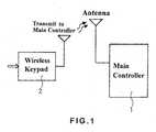
- Fig. 1is a block diagram of an antitheft system with clip-on wireless keypad according to the present invention.
- the antitheft system of Fig. 1includes a main controller 1 mounted in a car for controlling an overall operation of the anti-theft system and the door locks of the car; and a wireless keypad 2 internally provided with a keypad circuit, a battery, and a wireless transmission circuit (not shown), and externally provided with a clip 21 for connecting the wireless keypad 2 to an edge of a car door 3.
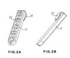
- Figs. 2A and 2Bare front and rear perspective views, respectively, of the wireless keypad 2 according to a first embodiment of thereof.
- the wireless keypad 2has an elongate body. On a front side of the elongate body of the wireless keypad 2, there are provided with a plurality of numbered keys 22.
- the clip 21is located at a rear side of the wireless keypad 2.
- the wireless keypad 2may be of any other shape.
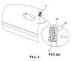
- Figs. 4A and 4Bare front and side perspective views, respectively, of a second embodiment of the wireless keypad 2 having a short rectangular body with the numbered keys 22 provided on a front side thereof and the clip 21 on a rear side thereof.
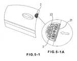
- Figs. 4-1A and 4-1Bare front and side perspective views, respectively, of a third embodiment of the wireless keypad 2 having a substantially semicircular body with the numbered keys 22 provided on a front side thereof and the clip 21 on a rear side thereof.
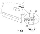
- the wireless keypad 2is designed for externally attaching to the edge of the car door 3 via the clip 21, and can therefore be mounted to all versions of different brands of cars without the need of drilling or wiring.
- a bonding agentis first applied to the rear side of the body of the wireless keypad 2 to fixedly bond the wireless keypad 2 to a desired position near the door edge.
- the wireless keypad 2may be more firmly held to the car door 3 without the risk of separating from the car door 3 due to vibration during driving or car washing. Since the clip 21 has a size larger than the gap between front and rear doors or the gap between the door and door frame, it is uneasy to externally detach the clip-on wireless keypad 2 from the car door 3 when door is closed.
- Figs. 6A1 and 6A2are front perspective and rear plan views, respectively, of a fourth embodiment of the wireless keypad 2.
- the clip 21is pivotally turnable so as to be angularly adjustable relative to the car door 3, allowing the wireless keypad 2 to be mounted to different car doors 3 that have different door edge inclinations.
- Figs. 6B1 and 6B2are front perspective and rear plan views, respectively, showing the clip 21 of the clip-on wireless keypad 2 in the fourth embodiment is turned leftward relative to the wireless keypad by an angle; and Figs. 6C1 and 6C2 are front perspective and rear plan views, respectively, showing the clip 21 of the clip-on wireless keypad 2 in the fourth embodiment is turned rightward relative to the wireless keypad by an angle.
- Figs. 7 and 7Ashows the mounting of the clip-on wireless keypad of the fourth embodiment to a car door edge.
- the wireless keypad 2may always be mounted to the car door 3 in parallel with a door handle or window frame thereof, so as to maintain the car door 3 in a beautiful and harmonious appearance.
- the clip-on wireless keypad 2 together with the main controller 1may form an antitheft system suitable for all versions of different brands of cars.
- a usermay conveniently press the predetermined numbered keys 22 to enter and transmit a code to the main controller 1 to release or enable the antitheft system of the present invention just beside the car. Therefore, the antitheft system with clip-on wireless keypad according to the present invention is a humanized design. That is, to enable the antitheft system and lock the car doors, the user needs only to press one or more predetermined keys 22 on the wireless keypad before he or she leaves the car. And, to release the antitheft system and unlock the car doors, the user needs only to press one or more correct number on the wireless keypad 2 just beside the car.
Landscapes
- Physics & Mathematics (AREA)
- General Physics & Mathematics (AREA)
- Engineering & Computer Science (AREA)
- Mechanical Engineering (AREA)
- Computer Networks & Wireless Communication (AREA)
- Lock And Its Accessories (AREA)
Abstract

Description
- The present invention relates to a novel auto antitheft system, and more particularly to a humanized antitheft system having a wireless keypad that may be clipped to a door edge of all versions of cars via a clip provided on a rear side of the wireless keypad, so that a user may conveniently use the wireless keypad just beside a car to enter and transmit a code to a main controller mounted in the car to release or enable the antitheft system.
- An automobile is an important traffic means in the modern society. It is a good thing to buy and own a car, and to conveniently go any place by driving. However, almost all the car owners have the bothersome problem of guarding the car against theft. A car thief would try different ways to steal a car, such as destroying the car lock, preparing a master key, destroying the door handle, driving away a car having the key left therein, etc. According to official investigations, an experienced thief needs only five minutes to steal a car. However, most car thieves would not take a risk and spend a lot of time to steal a car having an antitheft system mounted thereon.
- Therefore, there are various types of auto antitheft systems developed and available in the market, and these antitheft systems generally produce a deterrent effect by emitting a warning sound at the instant the car is invaded by a thief. The currently available auto antitheft systems are different in their performance and effect. The auto antitheft systems and remote-controlled power locks in early stages are generally controlled using a remote controller. However, an advanced original equipment antitheft system for car as shown in
Fig. 6 has been developed to save a user the trouble of carrying a remote controller or carelessly leaving the remote controller or a key in the car. In the antitheft system shown inFig. 8 , anumeral keypad 2a is provided near a door handle 3a. A user may conveniently enter a code by pressing numberedkeys 22a on thekeypad 2a to release or enable the auto antitheft system without the need of carrying the remote controller. The auto antitheft system with the keypad is therefore a convenient, advanced, and humanized design. - While it is very easy to provide such keypad on the door of a car as original equipment thereof, it is quite troublesome to additionally mount the keypad on the door of a car as an after-service because it is necessary to drill a hole on the car door for mounting the keypad, and then electrically connect the keypad to a main controller mounted in the car. And, most car owners are not willing to drill holes on their new cars for mounting the keypad.
- A currently available solution best for this problem is to bond a wireless keypad to a car door, so as to avoid drilling on the car door and therefore attract more customers to mount this type of antitheft system. The wireless keypad is received in a case and internally provided with a key circuit, a battery, and a wireless transmission circuit. However, the wireless keypad bonded to the car door tends to be easily stolen by a thief or separated from the car door due to car washing or vibration in driving.
- It is therefore tried by the inventor to develop an antitheft system with clip-on wireless keypad to overcome the above-mentioned problems.
- An antitheft system with clip-on wireless keypad according to the present invention includes a main controller mounted in a car for controlling an overall operation of the antitheft system, and a wireless keypad provided on a front side with numbered keys and on a rear side with a clip. The wireless keypad may be attached to a car door edge of all versions of different brands of cars via the clip without the risk of separating from the door easily. The wireless keypad also allows a user to enter and transmit a code to the main controller to release or enable the antitheft system just beside the car, and is therefore a humanized design.
- The structure and the technical means adopted by the present invention to achieve the above and other objects can be best understood by referring to the following detailed description of the preferred embodiments and the accompanying drawings, wherein
Fig. 1 is a block diagram of an antitheft system with clip-on wireless keypad according to the present invention;Fig. 2A is a front perspective view of a first embodiment of the clip-on wireless keypad included in the antitheft system of the present invention;Fig. 2B is a rear perspective view of the clip-on wireless keypad ofFig. 2A ;Fig. 3 shows the mounting of the clip-on wireless keypad ofFig. 2 to a car door edge;Fig. 3A is a partially enlarged view ofFig. 3 ;Fig. 4A is a front perspective view of a second embodiment of the clip-on wireless keypad included in the antitheft system of the present invention;Fig. 4B is a side perspective view of the clip-on wireless keypad ofFig. 4A ;Fig. 4-1A is a front perspective view of a third embodiment of the clip-on wireless keypad included in the antitheft system of the present invention;Fig. 4-1B is a side perspective view of the clip-on wireless keypad ofFig. 4-1A ;Fig. 5 shows the mounting of the clip-on wireless keypad ofFig. 4 to a car door edge;Fig. 5A is a partially enlarged view ofFig. 5 ;Fig. 5-1 shows the mounting of the clip-on wireless keypad ofFig. 4-1 to a car door edge;Fig. 5-1A is a partially enlarged view ofFig. 5-1 ;Figs. 6A1 and 6A2 are front perspective and rear plan views, respectively, of a fourth embodiment of the clip-on wireless keypad included in the antitheft system of the present invention, wherein the wireless keypad has an angularly adjustable clip;Figs. 6B1 and 6B2 are front perspective and rear plan views, respectively, showing the clip of the wireless keypad ofFigs. 6A1 and 6A2 is turned leftward relative to the wireless keypad by an angle;Figs. 6C1 and 6C2 are front perspective and rear plan views, respectively, showing the clip of the wireless keypad ofFigs. 6A1 and 6A2 is turned rightward relative to the wireless keypad by an angle;Fig. 7 shows the mounting of the clip-on wireless keypad ofFig. 6 to a car door edge;Fig. 7A is a partially enlarged view ofFig. 7 ; andFig. 8 shows an original equipment antitheft wireless keypad mounted on a car door.- Please refer to
Fig. 1 that is a block diagram of an antitheft system with clip-on wireless keypad according to the present invention. As shown, the antitheft system ofFig. 1 includes amain controller 1 mounted in a car for controlling an overall operation of the anti-theft system and the door locks of the car; and awireless keypad 2 internally provided with a keypad circuit, a battery, and a wireless transmission circuit (not shown), and externally provided with aclip 21 for connecting thewireless keypad 2 to an edge of acar door 3. Figs. 2A and 2B are front and rear perspective views, respectively, of thewireless keypad 2 according to a first embodiment of thereof. In this first embodiment, thewireless keypad 2 has an elongate body. On a front side of the elongate body of thewireless keypad 2, there are provided with a plurality of numberedkeys 22. Theclip 21 is located at a rear side of thewireless keypad 2. Of course, thewireless keypad 2 may be of any other shape.Figs. 4A and 4B are front and side perspective views, respectively, of a second embodiment of thewireless keypad 2 having a short rectangular body with the numberedkeys 22 provided on a front side thereof and theclip 21 on a rear side thereof.Figs. 4-1A and 4-1B are front and side perspective views, respectively, of a third embodiment of thewireless keypad 2 having a substantially semicircular body with the numberedkeys 22 provided on a front side thereof and theclip 21 on a rear side thereof.- Please refer to
Figs. 3, 3A ;5 ,5A ; and5-1, 5-1A . Thewireless keypad 2 is designed for externally attaching to the edge of thecar door 3 via theclip 21, and can therefore be mounted to all versions of different brands of cars without the need of drilling or wiring. To mount thewireless keypad 2 to thecar door 3, a bonding agent is first applied to the rear side of the body of thewireless keypad 2 to fixedly bond thewireless keypad 2 to a desired position near the door edge. With theclip 21, thewireless keypad 2 may be more firmly held to thecar door 3 without the risk of separating from thecar door 3 due to vibration during driving or car washing. Since theclip 21 has a size larger than the gap between front and rear doors or the gap between the door and door frame, it is uneasy to externally detach the clip-onwireless keypad 2 from thecar door 3 when door is closed. - Please refer to
Figs. 6A1 and 6A2 that are front perspective and rear plan views, respectively, of a fourth embodiment of thewireless keypad 2. In the fourth embodiment, theclip 21 is pivotally turnable so as to be angularly adjustable relative to thecar door 3, allowing thewireless keypad 2 to be mounted todifferent car doors 3 that have different door edge inclinations. Figs. 6B1 and 6B2 are front perspective and rear plan views, respectively, showing theclip 21 of the clip-onwireless keypad 2 in the fourth embodiment is turned leftward relative to the wireless keypad by an angle; andFigs. 6C1 and 6C2 are front perspective and rear plan views, respectively, showing theclip 21 of the clip-onwireless keypad 2 in the fourth embodiment is turned rightward relative to the wireless keypad by an angle.Figs. 7 and 7A shows the mounting of the clip-on wireless keypad of the fourth embodiment to a car door edge. As shown, with theturnable clip 21, thewireless keypad 2 may always be mounted to thecar door 3 in parallel with a door handle or window frame thereof, so as to maintain thecar door 3 in a beautiful and harmonious appearance.- The clip-on
wireless keypad 2 together with themain controller 1 may form an antitheft system suitable for all versions of different brands of cars. With the clip-onwireless keypad 2 mounted on thecar door 3, a user may conveniently press the predetermined numberedkeys 22 to enter and transmit a code to themain controller 1 to release or enable the antitheft system of the present invention just beside the car. Therefore, the antitheft system with clip-on wireless keypad according to the present invention is a humanized design. That is, to enable the antitheft system and lock the car doors, the user needs only to press one or morepredetermined keys 22 on the wireless keypad before he or she leaves the car. And, to release the antitheft system and unlock the car doors, the user needs only to press one or more correct number on thewireless keypad 2 just beside the car. - The present invention has been described with some preferred embodiments thereof and it is understood that many changes and modifications in the described embodiments can be carried out without departing from the scope and the spirit of the invention that is intended to be limited only by the appended claims.
Claims (4)
- An antitheft system with clip-on wireless keypad, comprising a main controller and a wireless keypad; the main controller being mounted in a car for controlling an overall operation of the antitheft system and door locks of the car; and the wireless keypad being provided with a clip for connecting the wireless keypad to an edge of a door of the car, so that a user may pressing predetermined keys on the wireless keypad to enter and transmit a code signal to the main controller to release or enable the antitheft system; wherein the clip on the wireless keypad has a size larger than the gap between front and rear doors or the gap between the door and door frame, preventing the wireless keypad from being externally detached from the door edge once the car door is closed; and the wireless keypad works with the main controller to allow a user to release or enable the antitheft system just beside the car without the need of carrying a remote controller, making the antitheft system a humanized design.
- The antitheft system with clip-on wireless keypad as claimed in claim 1, wherein the wireless keypad has an elongate body, and the keys and the clip of the wireless keypad are provided on a front and a rear side, respectively, of the elongate body.
- The antitheft system with clip-on wireless keypad as claimed in claim 1, wherein the wireless keypad may be of any shape with the keys and the clip respectively provided on a front and a rear side thereof.
- The antitheft system with clip-on wireless keypad as claimed in claim 1, wherein the clip is pivotally turnable to allow an angular adjustment of the clip relative to the wireless keypad, so that the wireless keypad may be mounted to car doors having different edge inclinations and always kept in parallel with a door handle or window frame of the car door to maintain the car door in a beautiful and harmonious appearance.
Priority Applications (2)
| Application Number | Priority Date | Filing Date | Title |
|---|---|---|---|
| DE200760006619DE602007006619D1 (en) | 2007-01-29 | 2007-01-29 | Anti-theft system with wireless keypad |
| EP20070001925EP1950711B1 (en) | 2007-01-29 | 2007-01-29 | Anti-theft system with clip-on wireless keypad |
Applications Claiming Priority (1)
| Application Number | Priority Date | Filing Date | Title |
|---|---|---|---|
| EP20070001925EP1950711B1 (en) | 2007-01-29 | 2007-01-29 | Anti-theft system with clip-on wireless keypad |
Publications (2)
| Publication Number | Publication Date |
|---|---|
| EP1950711A1true EP1950711A1 (en) | 2008-07-30 |
| EP1950711B1 EP1950711B1 (en) | 2010-05-19 |
Family
ID=38196554
Family Applications (1)
| Application Number | Title | Priority Date | Filing Date |
|---|---|---|---|
| EP20070001925Not-in-forceEP1950711B1 (en) | 2007-01-29 | 2007-01-29 | Anti-theft system with clip-on wireless keypad |
Country Status (2)
| Country | Link |
|---|---|
| EP (1) | EP1950711B1 (en) |
| DE (1) | DE602007006619D1 (en) |
Cited By (1)
| Publication number | Priority date | Publication date | Assignee | Title |
|---|---|---|---|---|
| CN115387679A (en)* | 2022-09-23 | 2022-11-25 | 中山亿联智能科技有限公司 | Small intelligent padlock unlocked based on three keys and unlocking method thereof |
Citations (4)
| Publication number | Priority date | Publication date | Assignee | Title |
|---|---|---|---|---|
| US3544804A (en)* | 1968-12-16 | 1970-12-01 | David D Gaumer | Sequence initiated electrical activator |
| WO1996003563A1 (en)* | 1994-07-26 | 1996-02-08 | Medeco Security Locks, Inc. | Electronic combination lock security system |
| EP0950784A2 (en)* | 1998-04-16 | 1999-10-20 | James P. Burgess | Keyless entry system for vehicles in particular |
| DE20300984U1 (en)* | 2003-01-23 | 2004-06-03 | Reime, Gerd | Keyless locking and unlocking system |
- 2007
- 2007-01-29DEDE200760006619patent/DE602007006619D1/enactiveActive
- 2007-01-29EPEP20070001925patent/EP1950711B1/ennot_activeNot-in-force
Patent Citations (4)
| Publication number | Priority date | Publication date | Assignee | Title |
|---|---|---|---|---|
| US3544804A (en)* | 1968-12-16 | 1970-12-01 | David D Gaumer | Sequence initiated electrical activator |
| WO1996003563A1 (en)* | 1994-07-26 | 1996-02-08 | Medeco Security Locks, Inc. | Electronic combination lock security system |
| EP0950784A2 (en)* | 1998-04-16 | 1999-10-20 | James P. Burgess | Keyless entry system for vehicles in particular |
| DE20300984U1 (en)* | 2003-01-23 | 2004-06-03 | Reime, Gerd | Keyless locking and unlocking system |
Cited By (1)
| Publication number | Priority date | Publication date | Assignee | Title |
|---|---|---|---|---|
| CN115387679A (en)* | 2022-09-23 | 2022-11-25 | 中山亿联智能科技有限公司 | Small intelligent padlock unlocked based on three keys and unlocking method thereof |
Also Published As
| Publication number | Publication date |
|---|---|
| EP1950711B1 (en) | 2010-05-19 |
| DE602007006619D1 (en) | 2010-07-01 |
Similar Documents
| Publication | Publication Date | Title |
|---|---|---|
| US7595718B2 (en) | Antitheft system with clip-on wireless keypad | |
| US6389854B1 (en) | Computer lock | |
| US20060232380A1 (en) | Enclosure security device | |
| US5410898A (en) | Lock device capable of activating an electrical anti-theft system | |
| US20050046554A1 (en) | System and device for locking an automobile steering axis | |
| US20110193692A1 (en) | Anti-theft system for vehicle | |
| EP1950711B1 (en) | Anti-theft system with clip-on wireless keypad | |
| US20060266089A1 (en) | Hybrid key | |
| US6791455B2 (en) | Vandal-lock/starter-interlock | |
| JP3854838B2 (en) | Vehicle locking control device | |
| CN101169011A (en) | Wireless automobile door handle remote control key type anti-theft system | |
| US20060117818A1 (en) | Vehicle anti-theft device | |
| TW201004820A (en) | Advanced anti-theft system of vehicle | |
| US7259659B2 (en) | Motorcar burglarproof system | |
| DE9410369U1 (en) | Alarm system for vehicles such as two-wheeled vehicles or automobiles | |
| US20080180232A1 (en) | Auto anti-theft system with door-mount wireless remote-control pushbutton | |
| US10329808B2 (en) | Magnetic anti-theft lock system and method | |
| EP1950107B1 (en) | Auto anti-theft system with door-mount wireless remote-control pushbutton | |
| JP3131575U (en) | Clip-type wireless keyboard anti-theft structure | |
| KR101540279B1 (en) | Anti-theft device for motorcycle | |
| CN100354163C (en) | Automobile multifunctional anti-theft anti-robbery system | |
| KR20100002019A (en) | Locking device in a motor cycle for preventing theft | |
| WO2013078945A1 (en) | Built-in bicycle anti-theft lock | |
| US20240409061A1 (en) | Multi Alarm Device | |
| KR101846559B1 (en) | Method for saving battery in smart key system |
Legal Events
| Date | Code | Title | Description |
|---|---|---|---|
| PUAI | Public reference made under article 153(3) epc to a published international application that has entered the european phase | Free format text:ORIGINAL CODE: 0009012 | |
| AK | Designated contracting states | Kind code of ref document:A1 Designated state(s):AT BE BG CH CY CZ DE DK EE ES FI FR GB GR HU IE IS IT LI LT LU LV MC NL PL PT RO SE SI SK TR | |
| AX | Request for extension of the european patent | Extension state:AL BA HR MK RS | |
| 17P | Request for examination filed | Effective date:20080820 | |
| AKX | Designation fees paid | Designated state(s):DE FR | |
| GRAP | Despatch of communication of intention to grant a patent | Free format text:ORIGINAL CODE: EPIDOSNIGR1 | |
| RAP1 | Party data changed (applicant data changed or rights of an application transferred) | Owner name:CHEN, TSE-HSING | |
| RIN1 | Information on inventor provided before grant (corrected) | Inventor name:CHEN, TSE-HSING | |
| GRAS | Grant fee paid | Free format text:ORIGINAL CODE: EPIDOSNIGR3 | |
| GRAA | (expected) grant | Free format text:ORIGINAL CODE: 0009210 | |
| AK | Designated contracting states | Kind code of ref document:B1 Designated state(s):DE FR | |
| REF | Corresponds to: | Ref document number:602007006619 Country of ref document:DE Date of ref document:20100701 Kind code of ref document:P | |
| PLBE | No opposition filed within time limit | Free format text:ORIGINAL CODE: 0009261 | |
| STAA | Information on the status of an ep patent application or granted ep patent | Free format text:STATUS: NO OPPOSITION FILED WITHIN TIME LIMIT | |
| 26N | No opposition filed | Effective date:20110222 | |
| REG | Reference to a national code | Ref country code:DE Ref legal event code:R097 Ref document number:602007006619 Country of ref document:DE Effective date:20110221 | |
| PGFP | Annual fee paid to national office [announced via postgrant information from national office to epo] | Ref country code:FR Payment date:20130220 Year of fee payment:7 | |
| REG | Reference to a national code | Ref country code:DE Ref legal event code:R082 Ref document number:602007006619 Country of ref document:DE Representative=s name:KOTITSCHKE & HEURUNG PARTNERSCHAFT MBB PATENT-, DE Ref country code:DE Ref legal event code:R082 Ref document number:602007006619 Country of ref document:DE Representative=s name:KOTITSCHKE & HEURUNG PARTNERSCHAFT, DE Ref country code:DE Ref legal event code:R082 Ref document number:602007006619 Country of ref document:DE Representative=s name:KOTITSCHKE & HEURUNG PARTNERSCHAFT MBB, DE | |
| PGFP | Annual fee paid to national office [announced via postgrant information from national office to epo] | Ref country code:DE Payment date:20140129 Year of fee payment:8 | |
| REG | Reference to a national code | Ref country code:FR Ref legal event code:ST Effective date:20140930 | |
| PG25 | Lapsed in a contracting state [announced via postgrant information from national office to epo] | Ref country code:FR Free format text:LAPSE BECAUSE OF NON-PAYMENT OF DUE FEES Effective date:20140131 | |
| REG | Reference to a national code | Ref country code:DE Ref legal event code:R119 Ref document number:602007006619 Country of ref document:DE | |
| PG25 | Lapsed in a contracting state [announced via postgrant information from national office to epo] | Ref country code:DE Free format text:LAPSE BECAUSE OF NON-PAYMENT OF DUE FEES Effective date:20150801 |