EP1948390B1 - Auxiliary device for a portable tool - Google Patents
Auxiliary device for a portable toolDownload PDFInfo
- Publication number
- EP1948390B1 EP1948390B1EP06793979AEP06793979AEP1948390B1EP 1948390 B1EP1948390 B1EP 1948390B1EP 06793979 AEP06793979 AEP 06793979AEP 06793979 AEP06793979 AEP 06793979AEP 1948390 B1EP1948390 B1EP 1948390B1
- Authority
- EP
- European Patent Office
- Prior art keywords
- portable tool
- drive train
- auxiliary device
- tool according
- tool
- Prior art date
- Legal status (The legal status is an assumption and is not a legal conclusion. Google has not performed a legal analysis and makes no representation as to the accuracy of the status listed.)
- Active
Links
- 230000008878couplingEffects0.000claimsabstractdescription7
- 238000010168coupling processMethods0.000claimsabstractdescription7
- 238000005859coupling reactionMethods0.000claimsabstractdescription7
- 230000001681protective effectEffects0.000claimsdescription13
- 230000000903blocking effectEffects0.000description2
- 230000006835compressionEffects0.000description1
- 238000007906compressionMethods0.000description1
- 238000006073displacement reactionMethods0.000description1
- 230000001747exhibiting effectEffects0.000description1
- 238000003780insertionMethods0.000description1
- 230000037431insertionEffects0.000description1
- 230000003993interactionEffects0.000description1
- 238000003801millingMethods0.000description1
- 230000001960triggered effectEffects0.000description1
Images


Classifications
- B—PERFORMING OPERATIONS; TRANSPORTING
- B25—HAND TOOLS; PORTABLE POWER-DRIVEN TOOLS; MANIPULATORS
- B25F—COMBINATION OR MULTI-PURPOSE TOOLS NOT OTHERWISE PROVIDED FOR; DETAILS OR COMPONENTS OF PORTABLE POWER-DRIVEN TOOLS NOT PARTICULARLY RELATED TO THE OPERATIONS PERFORMED AND NOT OTHERWISE PROVIDED FOR
- B25F5/00—Details or components of portable power-driven tools not particularly related to the operations performed and not otherwise provided for
- B25F5/001—Gearings, speed selectors, clutches or the like specially adapted for rotary tools
- B—PERFORMING OPERATIONS; TRANSPORTING
- B27—WORKING OR PRESERVING WOOD OR SIMILAR MATERIAL; NAILING OR STAPLING MACHINES IN GENERAL
- B27C—PLANING, DRILLING, MILLING, TURNING OR UNIVERSAL MACHINES FOR WOOD OR SIMILAR MATERIAL
- B27C5/00—Machines designed for producing special profiles or shaped work, e.g. by rotary cutters; Equipment therefor
- B27C5/10—Portable hand-operated wood-milling machines; Routers
- Y—GENERAL TAGGING OF NEW TECHNOLOGICAL DEVELOPMENTS; GENERAL TAGGING OF CROSS-SECTIONAL TECHNOLOGIES SPANNING OVER SEVERAL SECTIONS OF THE IPC; TECHNICAL SUBJECTS COVERED BY FORMER USPC CROSS-REFERENCE ART COLLECTIONS [XRACs] AND DIGESTS
- Y10—TECHNICAL SUBJECTS COVERED BY FORMER USPC
- Y10T—TECHNICAL SUBJECTS COVERED BY FORMER US CLASSIFICATION
- Y10T279/00—Chucks or sockets
- Y10T279/34—Accessory or component
- Y10T279/3431—Chuck key
- Y10T279/3437—Safety feature; e.g., ejector, interlock
- Y—GENERAL TAGGING OF NEW TECHNOLOGICAL DEVELOPMENTS; GENERAL TAGGING OF CROSS-SECTIONAL TECHNOLOGIES SPANNING OVER SEVERAL SECTIONS OF THE IPC; TECHNICAL SUBJECTS COVERED BY FORMER USPC CROSS-REFERENCE ART COLLECTIONS [XRACs] AND DIGESTS
- Y10—TECHNICAL SUBJECTS COVERED BY FORMER USPC
- Y10T—TECHNICAL SUBJECTS COVERED BY FORMER US CLASSIFICATION
- Y10T409/00—Gear cutting, milling, or planing
- Y10T409/30—Milling
- Y10T409/30392—Milling with means to protect operative or machine [e.g., guard, safety device, etc.]
- Y—GENERAL TAGGING OF NEW TECHNOLOGICAL DEVELOPMENTS; GENERAL TAGGING OF CROSS-SECTIONAL TECHNOLOGIES SPANNING OVER SEVERAL SECTIONS OF THE IPC; TECHNICAL SUBJECTS COVERED BY FORMER USPC CROSS-REFERENCE ART COLLECTIONS [XRACs] AND DIGESTS
- Y10—TECHNICAL SUBJECTS COVERED BY FORMER USPC
- Y10T—TECHNICAL SUBJECTS COVERED BY FORMER US CLASSIFICATION
- Y10T409/00—Gear cutting, milling, or planing
- Y10T409/30—Milling
- Y10T409/306216—Randomly manipulated, work supported, or work following device
- Y10T409/306552—Randomly manipulated
- Y10T409/306608—End mill [e.g., router, etc.]
- Y—GENERAL TAGGING OF NEW TECHNOLOGICAL DEVELOPMENTS; GENERAL TAGGING OF CROSS-SECTIONAL TECHNOLOGIES SPANNING OVER SEVERAL SECTIONS OF THE IPC; TECHNICAL SUBJECTS COVERED BY FORMER USPC CROSS-REFERENCE ART COLLECTIONS [XRACs] AND DIGESTS
- Y10—TECHNICAL SUBJECTS COVERED BY FORMER USPC
- Y10T—TECHNICAL SUBJECTS COVERED BY FORMER US CLASSIFICATION
- Y10T409/00—Gear cutting, milling, or planing
- Y10T409/30—Milling
- Y10T409/308624—Milling with limit means to aid in positioning of cutter bit or work [e.g., gauge, stop, etc.]
- Y—GENERAL TAGGING OF NEW TECHNOLOGICAL DEVELOPMENTS; GENERAL TAGGING OF CROSS-SECTIONAL TECHNOLOGIES SPANNING OVER SEVERAL SECTIONS OF THE IPC; TECHNICAL SUBJECTS COVERED BY FORMER USPC CROSS-REFERENCE ART COLLECTIONS [XRACs] AND DIGESTS
- Y10—TECHNICAL SUBJECTS COVERED BY FORMER USPC
- Y10T—TECHNICAL SUBJECTS COVERED BY FORMER US CLASSIFICATION
- Y10T409/00—Gear cutting, milling, or planing
- Y10T409/30—Milling
- Y10T409/309352—Cutter spindle or spindle support
Definitions
- the inventionrelates to a hand tool accessory with a receptacle for an output shaft exhibiting motor-hand tool, and with a by rotation to open or close tool holder having driveline, which is connectable via a coupling device with the output shaft of the motor-hand tool.
- a coupling deviceis also in the document EP 0 920 950 A1 shown.
- Such a hand tool accessoryhas a receptacle into which a motor-hand tool is introduced to connect these two parts, for example, by clamping together reliable. Furthermore, the hand tool attachment has its own, powered by the motor-power tool drive train with a tool holder. Such a hand tool accessory serves to guide the tool holder provided with a tool, wherein the tool is displaced to a position which is independent of the position of the motor power tool. The need for a displacement of the drive train and the tool may be, for example, in achieving a poorly accessible with the motor power tool processing area of a workpiece. To displace the tool, the output shaft of the power tool is coupled to the driveline via a coupling device, such as a belt drive with pulleys or a shaft with gears. Also, such a hand tool accessory allows a versatile use of the hand tool.
- a coupling devicesuch as a belt drive with pulleys or a shaft with gears.
- the hand tool accessory according to the inventionhas a rotary locking device acting on the drive train. This acts directly and torsionally rigid on the provided with the tool holder drive train, replacing one of the otherwise required for opening or closing the tool holder tools. For a simple, convenient and safe changing a tool or adjusting the insertion depth of a tool in the tool holder is possible.
- the rotary locking devicehas an axially displaceable and acting on the drive train turnstile. This arrangement allows for a slim design of the outsourced powertrain.
- the coupling deviceis designed as a belt drive. This is characterized by easy handling, low-noise operation and low weight.
- the beltBy forming the belt as a toothed belt that meshes with toothed pulleys, the torque of the power tool can be transmitted to the drivetrain in a defined manner.
- the hand tool accessoryhas a Maschineng., This serves to position and guide the tool relative to the workpiece or the positioning and guiding of the workpiece relative to the hand tool accessory.
- the Maschinen Giabstützvorraumhas at least one contact surface on which the hand tool accessory can be performed on the workpiece or vice versa. If the motor-hand tool, for example, a router, so the hand tool accessory can be designed so that the cutter is driven, for example, located above the application plane drive train, but even completely or partially below the contact surface, so that the distance of the cutter end defines a depth of cut with this level.
- the Werk Swissabstützvorraumis designed to be height adjustable.
- Height adjustablemeans in this context that the distance of the tool relative to the contact surface can be varied. This can For example, the corresponding distance from a common component forming recording and drive train of the hand tool accessory device relative to the contact surface of the Maschinen Swissabstweilvorraum be varied.
- the drive trainis surrounded by a protective housing.
- the protective housingprotects the environment from hazards arising from the high-speed parts of the drive train and the drive train from external influences such as pollution.
- the protective housingis designed as a handle. This additional handle is suitable for precise guidance of the drive train with the tool.
- the protective housingis designed to insulate the operating heat, so that the protective housing can serve as a handle, for example, even at high mileage of the drive train.
- the protective housing and the drive trainare arranged laterally spaced to receive. With such an arrangement it is ensured that inaccessible parts of the workpiece, which can not be reached with the motor-hand tool, can be processed.
- a simple and inexpensive coupling devicesuch as a belt drive
- the drive trainhas a polygon, which cooperates with a non-rotatable, axially displaceable, mounted in the housing locking element of the rotary locking device in a locking position form-fitting.
- the polygonis arranged at the opposite end of the tool holder end of the drive train.
- the hand tool accessoryhas a force acting on the locking element, slidably mounted in the housing hand-operated element. This is arranged as close as possible to the rotary locking device in order to operate the rotary locking device and to make the release mechanism as simple and direct as possible.
- the drive trainit is possible for the drive train to be electrically insulated from the protective housing.
- the bearings of the drive trainare formed electrically insulating or there is an electrically insulating layer between the protective housing and the drive train with bearings arranged as completely surrounds the drive train as possible.
- the rotary locking devicealso has electrically insulating elements that electrically encapsulate the drive train. If the drive train is at a high electrical potential because the tool, for example, damages an electrical line such as the supply cable, there is no risk for the operator of an electric shock.
- FIG. 1a hand tool accessory 1 is shown for a motor hand tool, not shown.
- Serving as a receptacle 2 for the motor-power tool cuff 3has at one end a tensioning device 4 for fixing the sleeve 3 on the motor-hand tool.
- a mounting ring 5with a radially outwardly facing arm 6, at the end of which a rotatably mounted shaft 7 is located.
- a tool holder 8At one End of this shaft 7 is a tool holder 8 for receiving a tool, not shown.
- the shaft 7 and the tool holder 8belong to a drive train 9 for driving the tool.
- the drive train 9is rotatably mounted with bearings 10 in a housing 11 integrally connected to the boom 6.
- a rotary locking device 13which can be actuated with a manual actuating element 12 and which is held in the non-triggered state by a spiral spring 14 during tool operation.
- the mounting ring 5 of the hand tool attachment 1is mounted on an annular base 15 which is completely surrounded by the mounting ring 5, axially displaceable.
- the base 15is connected on the side facing away from the sleeve 3 with a base plate 16, with which it forms a Maschinen sangtützvorraum 17.
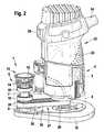
- the FIG. 2shows the hand tool accessory 1 with a located in the receptacle 2 motor-power tool 22, which is designed as a router 23.
- the router 23has, in an upper end region, a connection of a power cable 24 at the side and an on / off switch 25 on the opposite side.
- the output shaft of the routerAt the opposite end is the output shaft of the router to which a tool holder is in operation without hand tool attachment 1.
- Thisis replaced by a belt drive driving belt pulley 28.
- the belt drive 27drives the drive train 9 with the tool holder 8 via another belt pulley 28.
- thismay be formed as a toothed belt 30; which meshes with the teeth of the pulleys 28.
- FIG. 3shows in an exploded view the structure of the drive train 9 on the boom 6, and the structure of the rotary locking device 13 with an axially displaceable acting on the drive train turnstile 31.
- the shaft 7 of the drive train 9is rotatably mounted with the bearings 10 in the housing 11.
- At one end the shaft 7is the tool holder 8, which receives a cutter as a tool in the hand tool accessory 1 shown here for a router 23.
- the tool holder 8 shown hereis opened or closed and fixed by turning the counter element 32 against the shaft 7.
- On the shaft 7, in the immediate vicinity of the tool holder 8is the pulley 28 through which the entire drive train 9 is driven.
- the shaft 7according to FIG.
- a coil spring 14surrounds the end of the drive train 9 with the square 33 and pushes a locking element 35, and the manual operating element 12 axially against a cover ring 37 of the housing 11, so that these parts are arranged axially spaced from the drive train 9. If the manual actuating element 12 is actuated, the non-rotatably mounted blocking element 35 is pushed over the polygonal 33 in the case of a corresponding rotational position of the drive train 9 in order to cooperate with it in a form-locking manner.
- FIG. 4shows in detail the interaction of the formed as a square 33 polygon 34 at the end of the drive train 9 with the housing 11 by grooves 38 non-rotatably axially mounted locking element 35.
- the grooves 38suitably engage projections of the locking element 35 a. If the manual operating element 12, not shown, actuated, the drive train 9 can be locked in a suitable rotational position of the drive train 9, which is achieved in this arrangement by rotation of the drive train 9 every 180 °.
- the height adjustment of the hand tool accessory 1 by the adjusting screw 18is designed so that this, supported by a pin 19 in the base 15, between this and the mounting ring 5, wherein the trained as a thumbscrew head of the adjusting screw 18 through a recess in the mounting ring 5 is easily accessible from the outside.
- the threaded element of the adjusting screw 18is arranged between a semicircular, axially extending groove on the outer surface of the base 15 and a threaded semi-circular groove in the interior of the mounting ring 5 surrounding the base 15.
- the adjusting screwengages in the thread of the mounting ring 5, so that it can be raised or lowered by turning the adjusting screw.
- thisis also supported by a compression spring surrounding it, which reduces the friction between the base 15 and adjusting screw 18.
Landscapes
- Life Sciences & Earth Sciences (AREA)
- Engineering & Computer Science (AREA)
- Mechanical Engineering (AREA)
- Wood Science & Technology (AREA)
- Forests & Forestry (AREA)
- Milling, Drilling, And Turning Of Wood (AREA)
- Portable Nailing Machines And Staplers (AREA)
Abstract
Description
Translated fromGermanDie Erfindung betrifft eine Handwerkzeug-Zusatzeinrichtung mit einer Aufnahme für ein eine Abtriebswelle aufweisendes Motor-Handwerkzeug, und mit einem eine durch Drehung zu öffnende beziehungsweise zu schließende Werkzeugaufnahme aufweisenden Antriebsstrang, der über eine Kupplungseinrichtung mit der Abtriebswelle des Motor-Handwerkzeugs verbindbar ist. Eine solche Vorrichtung ist auch im Dokument
Eine derartige Handwerkzeug-Zusatzeinrichtung ist bekannt. Sie weist eine Aufnahme auf, in die ein Motor-Handwerkzeug eingeführt wird, um diese beiden Teile zum Beispiel durch Verspannen miteinander betriebssicher zu verbinden. Ferner besitzt die Handwerkzeug-Zusatzeinrichtung einen eigenen, von dem Motor-Handwerkzeug angetriebenen Antriebsstrang mit einer Werkzeugaufnahme. Eine solche Handwerkzeug-Zusatzeinrichtung dient zum Führen der mit einem Werkzeug versehenen Werkzeugaufnahme, wobei das Werkzeug an eine Position verlagert ist, die unabhängig von der Position des Motor-Handwerkzeugs ist. Die Notwendigkeit einer Verlagerung des Antriebsstrangs und des Werkzeugs kann zum Beispiel im Erreichen eines mit dem Motor-Handwerkzeug schlecht zugänglichen Bearbeitungsbereichs eines Werkstücks liegen. Um das Werkzeug zu verlagern wird die Abtriebswelle des Motor-Handwerkzeugs mit dem Antriebsstrang über eine Kupplungseinrichtung, wie zum Beispiel einem Riementrieb mit Riemenrädern oder einer Welle mit Zahnrädern, gekuppelt. Auch ermöglicht eine derartige Handwerkzeug-Zusatzeinrichtung einen vielseitigen Einsatz des Handwerkzeugs.Such a hand tool accessory is known. It has a receptacle into which a motor-hand tool is introduced to connect these two parts, for example, by clamping together reliable. Furthermore, the hand tool attachment has its own, powered by the motor-power tool drive train with a tool holder. Such a hand tool accessory serves to guide the tool holder provided with a tool, wherein the tool is displaced to a position which is independent of the position of the motor power tool. The need for a displacement of the drive train and the tool may be, for example, in achieving a poorly accessible with the motor power tool processing area of a workpiece. To displace the tool, the output shaft of the power tool is coupled to the driveline via a coupling device, such as a belt drive with pulleys or a shaft with gears. Also, such a hand tool accessory allows a versatile use of the hand tool.
Bei einer Werkzeugaufnahme, die durch Drehung geöffnet beziehungsweise geschlossen wird, müssen in vielen Fällen zwei Komponenten der Werkzeugaufnahme durch Drehen gegeneinander festgezogen, beziehungsweise von einander gelöst werden. Um ein entsprechendes Drehmoment zu erreichen werden in der Regel zwei Werkzeuge benötigt.In a tool holder, which is opened or closed by rotation, in many cases, two components of the tool holder must be tightened by turning against each other, or released from each other become. In order to achieve a corresponding torque usually two tools are needed.
Die erfindungsgemäße Handwerkzeug-Zusatzeinrichtung hat eine am Antriebsstrang angreifende Dreharretiervorrichtung. Diese wirkt direkt und drehstarr auf den mit der Werkzeugaufnahme versehenen Antriebsstrang und ersetzt dabei eines der sonst zum Öffnen beziehungsweise Schließen der Werkzeugaufnahme benötigten Werkzeuge. Damit ist ein einfaches, bequemes und sicheres Wechseln eines Werkzeugs beziehungsweise Einstellen der Einstecktiefe eines Werkzeugs in der Werkzeugaufnahme möglich.The hand tool accessory according to the invention has a rotary locking device acting on the drive train. This acts directly and torsionally rigid on the provided with the tool holder drive train, replacing one of the otherwise required for opening or closing the tool holder tools. For a simple, convenient and safe changing a tool or adjusting the insertion depth of a tool in the tool holder is possible.
Vorzugsweise weist die Dreharretiervorrichtung dabei eine axial verlagerbare und auf den Antriebsstrang wirkende Drehsperre auf. Diese Anordnung lässt eine schlanke Bauweise des ausgelagerten Antriebsstrangs zu.Preferably, the rotary locking device has an axially displaceable and acting on the drive train turnstile. This arrangement allows for a slim design of the outsourced powertrain.
Nach einer bevorzugten Ausführungsform ist die Kupplungseinrichtung als Riementrieb ausgebildet. Dieser zeichnet sich durch eine einfache Handhabung, einen geräuscharmen Lauf und geringes Gewicht aus. Durch Ausbilden des Riemens als Zahnriemen, der mit Zahnriemenrädern kämmt, kann das Drehmoment des Motor-Handwerkzeugs definiert auf den Antriebsstrang übertragen werden.According to a preferred embodiment, the coupling device is designed as a belt drive. This is characterized by easy handling, low-noise operation and low weight. By forming the belt as a toothed belt that meshes with toothed pulleys, the torque of the power tool can be transmitted to the drivetrain in a defined manner.
Nach einer Weiterbildung der Erfindung ist vorgesehen, dass die Handwerkzeug-Zusatzeinrichtung eine Werkstückabstützvorrichtung aufweist. Diese dient zur Positionierung und Führung des Werkzeuges gegenüber dem Werkstück beziehungsweise der Positionierung und Führung des Werkstücks gegenüber der Handwerkzeug-Zusatzeinrichtung. Dazu besitzt die Werkstückabstützvorrichtung mindestens eine Anlegefläche, an der die Handwerkzeug-Zusatzeinrichtung auf dem Werkstück geführt werden kann oder umgekehrt. Ist das Motor-Handwerkzeug zum Beispiel eine Oberfräse, so kann die Handwerkzeug-Zusatzeinrichtung derart gestaltet sein, dass der Fräser zum Beispiel vom oberhalb der Anlegeebene befindlichen Antriebsstrang angetrieben wird, selbst jedoch ganz oder teilweise unterhalb der Anlegefläche liegt, so dass der Abstand des Fräserendes mit dieser Ebene eine Schnitttiefe definiert.According to a development of the invention it is provided that the hand tool accessory has a Werkstückabstützvorrichtung. This serves to position and guide the tool relative to the workpiece or the positioning and guiding of the workpiece relative to the hand tool accessory. For this purpose, the Werkstückabstützvorrichtung has at least one contact surface on which the hand tool accessory can be performed on the workpiece or vice versa. If the motor-hand tool, for example, a router, so the hand tool accessory can be designed so that the cutter is driven, for example, located above the application plane drive train, but even completely or partially below the contact surface, so that the distance of the cutter end defines a depth of cut with this level.
Insbesondere ist vorgesehen, dass die Werkstückabstützvorrichtung höhenverstellbar ausgebildet ist. Höhenverstellbar heißt in diesem Zusammenhang, dass der Abstand des Werkzeugs gegenüber der Anlegefläche variiert werden kann. Dazu kann zum Beispiel der entsprechende Abstand von ein gemeinsames Bauteil bildenden Aufnahme und Antriebsstrang der Handwerkzeug-Zusatzeinrichtung gegenüber der Anlegefläche der Werkstückabstützvorrichtung variiert werden.In particular, it is provided that the Werkstückabstützvorrichtung is designed to be height adjustable. Height adjustable means in this context that the distance of the tool relative to the contact surface can be varied. This can For example, the corresponding distance from a common component forming recording and drive train of the hand tool accessory device relative to the contact surface of the Werkstückabstützvorrichtung be varied.
Nach einer Weiterbildung der Erfindung ist vorgesehen, dass der Antriebsstrang von einem Schutzgehäuse umgeben ist. Das Schutzgehäuse schützt die Umwelt vor Gefahren, die von den schnelldrehenden Teilen des Antriebsstrangs ausgehen, sowie den Antriebsstrang vor äußeren Einflüssen wie zum Beispiel Verschmutzung. Insbesondere ist es möglich, die Lager des Antriebsstrangs elektrisch isolierend auszubilden.According to a development of the invention, it is provided that the drive train is surrounded by a protective housing. The protective housing protects the environment from hazards arising from the high-speed parts of the drive train and the drive train from external influences such as pollution. In particular, it is possible to form the bearings of the drive train electrically insulating.
Insbesondere ist vorgesehen, dass das Schutzgehäuse als Handgriff ausgebildet ist. Dieser zusätzliche Griff eignet sich zur präzisen Führung des Antriebsstrangs mit dem Werkzeug.In particular, it is provided that the protective housing is designed as a handle. This additional handle is suitable for precise guidance of the drive train with the tool.
Ferner ist es vorteilhaft, wenn das Schutzgehäuse betriebswärmeisolierend ausgebildet ist, sodass das Schutzgehäuse zum Beispiel auch bei hoher Laufleistung des Antriebsstrangs als Handgriff dienen kann.Furthermore, it is advantageous if the protective housing is designed to insulate the operating heat, so that the protective housing can serve as a handle, for example, even at high mileage of the drive train.
Nach einer Weiterbildung der Erfindung ist vorgesehen, dass das Schutzgehäuse und der Antriebsstrang seitlich beabstandet zur Aufnahme angeordnet sind. Bei einer solchen Anordnung ist gewährleistet, dass unzugängliche Teile des Werkstücks, die mit dem Motor-Handwerkzeug nicht erreichbar sind, bearbeitet werden können.According to a development of the invention it is provided that the protective housing and the drive train are arranged laterally spaced to receive. With such an arrangement it is ensured that inaccessible parts of the workpiece, which can not be reached with the motor-hand tool, can be processed.
Vorzugswiese ist dabei der Antriebsstrang parallel beabstandet zur Abtriebswelle des sich in der Aufnahme befindenden Motor-Handwerkzeugs angeordnet, sodass eine einfache und preiswerte Kupplungseinrichtung, wie zum Beispiel ein Riementrieb, zur Kupplung von Antriebsstrang und Abtriebswelle des Motor-Handwerkzeugs genutzt werden kann.Preference meadow while the drive train is arranged parallel spaced from the output shaft of the motor-hand tool located in the receptacle, so that a simple and inexpensive coupling device, such as a belt drive, can be used to connect the drive train and output shaft of the motor hand tool.
Insbesondere ist vorgesehen, dass der Antriebsstrang einen Mehrkant aufweist, der mit einem undrehbaren, axial verschieblichen, im Gehäuse gelagerten Sperrelement der Dreharretiervorrichtung in Arretierstellung formschlüssig zusammenwirkt.In particular, it is provided that the drive train has a polygon, which cooperates with a non-rotatable, axially displaceable, mounted in the housing locking element of the rotary locking device in a locking position form-fitting.
Vorzugsweise ist der Mehrkant an dem der Werkzeugaufnahme gegenüberliegenden Ende des Antriebsstrangs angeordnet.Preferably, the polygon is arranged at the opposite end of the tool holder end of the drive train.
Bei einer Weiterbildung der Erfindung weist die Handwerkzeug-Zusatzeinrichtung ein auf das Sperrelement wirkendes, im Gehäuse verschieblich gelagertes Handbetätigungselement auf. Dieses ist möglichst nah an der Dreharretiervorrichtung angeordnet, um die Dreharretiervorrichtung zu bedienen und um den Auslösemechanismus möglichst einfach und direkt zu gestalten.In a further development of the invention, the hand tool accessory has a force acting on the locking element, slidably mounted in the housing hand-operated element. This is arranged as close as possible to the rotary locking device in order to operate the rotary locking device and to make the release mechanism as simple and direct as possible.
Insbesondere ist es möglich, dass der Antriebsstrang elektrisch isoliert von dem Schutzgehäuse ist. Dazu sind die Lager des Antriebsstrangs elektrisch isolierend ausgebildet oder es ist eine elektrisch isolierende Schicht zwischen dem Schutzgehäuse und dem Antriebsstrang mit Lagern angeordnet, die den Antriebsstrang möglichst vollständig umgibt. Die Dreharretiervorrichtung weist ebenfalls elektrisch isolierende Elemente auf, die den Antriebsstrang elektrisch kapseln. Liegt der Antriebsstrang auf einem hohen elektrischen Potential, weil das Werkzeug zum Beispiel eine elektrische Leitung wie das Zuleitungskabel beschädigt, so besteht für den Bediener nicht die Gefahr eines elektrischen Schlages.In particular, it is possible for the drive train to be electrically insulated from the protective housing. For this purpose, the bearings of the drive train are formed electrically insulating or there is an electrically insulating layer between the protective housing and the drive train with bearings arranged as completely surrounds the drive train as possible. The rotary locking device also has electrically insulating elements that electrically encapsulate the drive train. If the drive train is at a high electrical potential because the tool, for example, damages an electrical line such as the supply cable, there is no risk for the operator of an electric shock.
Die Erfindung wird nachfolgend in einem Ausführungsbeispiel anhand der zugehörigen Zeichnungen näher erläutert. Es zeigt
Figur 1- eine Seitenansicht einer Handwerkzeug-Zusatzeinrich-tung,
Figur 2- eine Seitenansicht einer ein Motorhandwerkzeug bildenden Oberfräse mit einer Handwerkzeug-Zusatzein-richtung,
Figur 3- eine Explosionszeichnung eines Antriebsstrangs der Handwerkzeug- Zusatzeinrichtung und
- Figur 4
- eine Detailzeichnung einer am Antriebsstrang angreifenden Dreharre- tiervorrichtung.
- FIG. 1
- a side view of a hand tool accessory,
- FIG. 2
- 3 a side view of a motor cutter forming a router with a hand tool attachment,
- FIG. 3
- an exploded view of a drive train of the hand tool accessory and
- FIG. 4
- a detailed drawing of an attacking on the drive train Dreharre- animal device.
In
Die
Die
Die
Die Höhenverstellung der Handwerkzeug-Zusatzeinrichtung 1 durch die Justierschraube 18 ist so gestaltet, dass sich diese, durch einen Stift 19 im Sockel 15 gestützt, zwischen diesem und dem Befestigungsring 5 befindet, wobei der als Rändelschraube ausgebildete Kopf der Justierschraube 18 durch eine Aussparung im Befestigungsring 5 von außen gut erreichbar ist. Das Gewindeelement der Justierschraube 18 ist zwischen einer halbkreisförmigen, axial verlaufenden Nut an der Außenfläche des Sockels 15 und einer mit einem Gewinde versehenen halbkreisförmigen Nut im Inneren des den Sockel 15 umgebenden Befestigungsrings 5 angeordnete. Die Justierschraube greift in das Gewinde des Befestigungsrings 5, sodass dieser durch Drehen der Justierschraube angehoben oder abgesenkt werden kann. Neben der Führung der Justierschraube 18 durch den im Sockel 15 befestigten Stift 19 wird diese auch durch eine sie umgebende Druckfeder unterstützt, die die Reibung zwischen Sockel 15 und Justierschraube 18 reduziert.The height adjustment of the
Claims (14)
- Auxiliary device for a portable tool, comprising a receptacle for a motor-operated portable tool having an output shaft, and comprising a drive train which has a tool receptacle to be opened or closed by rotation and which can be connected to the output shaft of the motor-operated portable tool via a coupling device,characterized by a rotation-arresting device (13) acting on the drive train (9).
- Auxiliary device for a portable tool according to Claim 1,characterized in that the rotation-arresting device (13) has an axially displaceable rotation lock (31) acting on the drive train (9).
- Auxiliary device for a portable tool according to either of the preceding claims,characterized in that the coupling device is designed as a belt drive (27).
- Auxiliary device for a portable tool according to one of the preceding claims,characterized by a workpiece-supporting device (17).
- Auxiliary device for a portable tool according to one of the preceding claims,characterized in that the workpiece-supporting device (17) is designed to be vertically adjustable.
- Auxiliary device for a portable tool according to one of the preceding claims,characterized in that the drive train (9) is surrounded by a protective housing (36).
- Auxiliary device for a portable tool according to one of the preceding claims,characterized in that the protective housing (36) is designed as a handle (39).
- Auxiliary device for a portable tool according to one of the preceding claims,characterized in that the protective housing (36) is designed to insulate against heat generated during operation.
- Auxiliary device for a portable tool according to one of the preceding claims,characterized in that the protective housing (36) is arranged at a lateral distance from the receptacle (2)
- Auxiliary device for a portable tool according to one of the preceding claims,characterized in that the drive train (9) is arranged to run parallel to the output shaft of the motor-operated power tool (22) located in the receptacle (2).
- Auxiliary device for a portable tool according to one of the preceding claims,characterized in that the drive train (9) has a polygonal portion (34) which interacts with a non-rotatable locking element (35) in a positive-locking manner in the arresting position, said locking element (35) being mounted in the housing (11) in an axially displaceable manner.
- Auxiliary device for a portable tool according to one of the preceding claims,characterized in that the polygonal portion (34) is arranged on that end of the drive train (9) which is opposite the tool receptacle (8).
- Auxiliary device for a portable tool according to one of the preceding claims,characterized by a manual actuating element (12) acting on the locking element (35) and displaceably mounted in the housing (11).
- Auxiliary device for a portable tool according to one of the preceding claims,characterized in that the drive train (9) is electrically insulated from the protective housing (36).
Applications Claiming Priority (2)
| Application Number | Priority Date | Filing Date | Title |
|---|---|---|---|
| DE102005053534ADE102005053534A1 (en) | 2005-11-08 | 2005-11-08 | Hand Tool accessory |
| PCT/EP2006/067099WO2007054408A1 (en) | 2005-11-08 | 2006-10-05 | Auxiliary device for a portable tool |
Publications (2)
| Publication Number | Publication Date |
|---|---|
| EP1948390A1 EP1948390A1 (en) | 2008-07-30 |
| EP1948390B1true EP1948390B1 (en) | 2010-08-04 |
Family
ID=37663137
Family Applications (1)
| Application Number | Title | Priority Date | Filing Date |
|---|---|---|---|
| EP06793979AActiveEP1948390B1 (en) | 2005-11-08 | 2006-10-05 | Auxiliary device for a portable tool |
Country Status (5)
| Country | Link |
|---|---|
| US (1) | US7871227B2 (en) |
| EP (1) | EP1948390B1 (en) |
| CN (1) | CN101304837A (en) |
| DE (2) | DE102005053534A1 (en) |
| WO (1) | WO2007054408A1 (en) |
Families Citing this family (12)
| Publication number | Priority date | Publication date | Assignee | Title |
|---|---|---|---|---|
| US7719752B2 (en) | 2007-05-11 | 2010-05-18 | Qualcomm Mems Technologies, Inc. | MEMS structures, methods of fabricating MEMS components on separate substrates and assembly of same |
| US8678725B2 (en)* | 2009-02-13 | 2014-03-25 | Black & Decker Inc. | Router |
| US8628280B2 (en)* | 2009-02-13 | 2014-01-14 | Black & Decker Inc. | Router |
| US9149923B2 (en)* | 2010-11-09 | 2015-10-06 | Black & Decker Inc. | Oscillating tools and accessories |
| JP5697503B2 (en)* | 2011-03-22 | 2015-04-08 | 株式会社マキタ | Electric tool |
| US20130051951A1 (en)* | 2011-08-23 | 2013-02-28 | William Robert Friegang | Scribing Tool and Dust Collector |
| DE102011082263A1 (en)* | 2011-09-07 | 2013-03-07 | Robert Bosch Gmbh | Device for fine adjustment of portable machine tool e.g. router, has operation knob that is supported relative to housing unit, so that knob is movable along a direction different from direction of rotation axis of knob |
| DE102011088748A1 (en)* | 2011-12-15 | 2013-06-20 | Robert Bosch Gmbh | Portable machine tool e.g. oscillation hand-held power tool has insulating unit that is provided to insulate the sheath housing element that is electrically connected to projecting portion of the driven element |
| DE102016225719A1 (en)* | 2016-12-21 | 2018-06-21 | Robert Bosch Gmbh | Machine tool with at least one motor axis and one output shaft |
| CN212042789U (en) | 2019-05-15 | 2020-12-01 | 米沃奇电动工具公司 | router |
| SE1930193A1 (en)* | 2019-06-14 | 2020-12-15 | Atlas Copco Ind Technique Ab | TORQUE TRANSFERRING DEVICE FOR USE WITH A POWER TOOL |
| DE102020200922A1 (en) | 2020-01-27 | 2021-07-29 | Robert Bosch Gesellschaft mit beschränkter Haftung | Jig |
Family Cites Families (21)
| Publication number | Priority date | Publication date | Assignee | Title |
|---|---|---|---|---|
| US2777340A (en)* | 1955-09-28 | 1957-01-15 | Leonard J Hettwer | Offset drilling attachment |
| US3111969A (en)* | 1962-02-05 | 1963-11-26 | Arnold R Bivens | Portable undercutting saw |
| US3454061A (en)* | 1966-12-22 | 1969-07-08 | Rockwell Mfg Co | Power tool |
| US3494395A (en)* | 1967-02-08 | 1970-02-10 | Rockwell Mfg Co | Router |
| DE3006460C2 (en) | 1980-02-21 | 1985-10-31 | Institut Dr. Friedrich Förster Prüfgerätebau GmbH & Co KG, 7410 Reutlingen | Arrangement for making incisions on metal parts |
| US4400995A (en)* | 1981-09-23 | 1983-08-30 | Milwaukee Electric Tool Corporation | Spindle lock with impacting capability |
| US4461330A (en)* | 1982-08-06 | 1984-07-24 | Judkins Donald J | Portable woodworking power tool |
| CH656567A5 (en) | 1982-09-09 | 1986-07-15 | Blatty Ag | DEVICE FOR TRIMMING AND countersinking HOLES. |
| US4827996A (en)* | 1987-09-11 | 1989-05-09 | Robert Bosch Power Tool Corporation | Power tool for trimming laminate |
| US5013195A (en)* | 1989-05-15 | 1991-05-07 | Frank Strazar | Router guide |
| US5013196A (en)* | 1990-07-23 | 1991-05-07 | Friegang William R | Scribing accessory for offset router |
| US5902080A (en)* | 1997-07-11 | 1999-05-11 | Roto Zip Tool Corporation | Spiral cutting tool with detachable battery pack |
| US6042310A (en)* | 1997-12-01 | 2000-03-28 | Black & Decker, Inc. | Bit attaching arrangement for power tool |
| DE19754429C2 (en) | 1997-12-08 | 2002-11-21 | Eisenblaetter Gerd Gmbh | Manually manageable processing device with an extension unit |
| US6139228A (en)* | 1998-12-04 | 2000-10-31 | Stryker Corporation | Keyless chuck assembly for a rotary driven tool |
| US6224304B1 (en)* | 1999-03-09 | 2001-05-01 | Black & Decker, Inc. | Bit attaching arrangement for power tool |
| US6443675B1 (en)* | 2000-02-17 | 2002-09-03 | Roto Zip Tool Corporation | Hand-held power tool |
| DE10029898A1 (en) | 2000-06-17 | 2001-12-20 | Bosch Gmbh Robert | Hand tool; has tool chuck rotated by driven motor and driven shaft and having clamp device and has stop device arranged on driven shaft to secure or release clamp device against casing part |
| US6846138B1 (en)* | 2002-07-23 | 2005-01-25 | Porter-Cable Corporation | Offset base router |
| DE10359420A1 (en)* | 2003-12-18 | 2005-07-28 | Robert Bosch Gmbh | Hand tool |
| US20050139288A1 (en)* | 2003-12-31 | 2005-06-30 | Mair John F. | Offset router flush cutting base |
- 2005
- 2005-11-08DEDE102005053534Apatent/DE102005053534A1/ennot_activeWithdrawn
- 2006
- 2006-10-05WOPCT/EP2006/067099patent/WO2007054408A1/enactiveApplication Filing
- 2006-10-05EPEP06793979Apatent/EP1948390B1/enactiveActive
- 2006-10-05USUS11/908,813patent/US7871227B2/enactiveActive
- 2006-10-05DEDE502006007606Tpatent/DE502006007606D1/enactiveActive
- 2006-10-05CNCN200680041771.9Apatent/CN101304837A/enactivePending
Also Published As
| Publication number | Publication date |
|---|---|
| US7871227B2 (en) | 2011-01-18 |
| US20080199269A1 (en) | 2008-08-21 |
| DE102005053534A1 (en) | 2007-05-10 |
| CN101304837A (en) | 2008-11-12 |
| DE502006007606D1 (en) | 2010-09-16 |
| WO2007054408A1 (en) | 2007-05-18 |
| EP1948390A1 (en) | 2008-07-30 |
Similar Documents
| Publication | Publication Date | Title |
|---|---|---|
| EP1948390B1 (en) | Auxiliary device for a portable tool | |
| DE102007019434B4 (en) | Hand tool machine, in particular drilling or screwing device, with micro switch | |
| DE60313379T2 (en) | Rotating tool with flexible shaft with locking pin and end cap | |
| DE102009054923B4 (en) | Hand tool | |
| EP1800803B1 (en) | Hand tool with a ratchet striking mechanism | |
| DE102006001986A1 (en) | Clamping device for releasably securing a disc-shaped tool | |
| DE102011084499A1 (en) | tool attachment | |
| DE102010002352B4 (en) | Hand machine tool | |
| DE102007019436A1 (en) | Hand tool, in particular drilling or screwing | |
| DE102017103513A1 (en) | angular tool | |
| EP2895288A1 (en) | Hand-held machine tool | |
| EP2632641A1 (en) | Mechanical striking mechanism for a hand machine tool | |
| EP2029303B1 (en) | Reciprocating saw with a fastening device for a saw blade | |
| EP1228841A1 (en) | Electrical screwdriver with output torque limitation | |
| DE202017101409U1 (en) | Auxiliary handle and working tool | |
| DE102019111185A1 (en) | Clamping device for a screw connection | |
| EP2539094A1 (en) | Handheld machine tool | |
| WO2012010382A1 (en) | Handheld machine tool having a mechanical striking mechanism | |
| DE102014206244A1 (en) | Hand tool | |
| EP3558607A1 (en) | Power tool having at least one motor axis and one output axis | |
| EP2632642B1 (en) | Hand machine tool comprising a mechanical striking mechanism | |
| DE102010041045A1 (en) | Hand tool machine, in particular percussion drill | |
| DE10309057B4 (en) | Hand-operated implement with adjustable torque limiter | |
| CH688133A5 (en) | Tensioning device for a cutting hand tool, in particular motor file. | |
| DE102016224577A1 (en) | Hand tool |
Legal Events
| Date | Code | Title | Description |
|---|---|---|---|
| PUAI | Public reference made under article 153(3) epc to a published international application that has entered the european phase | Free format text:ORIGINAL CODE: 0009012 | |
| 17P | Request for examination filed | Effective date:20080609 | |
| AK | Designated contracting states | Kind code of ref document:A1 Designated state(s):DE FR GB | |
| DAX | Request for extension of the european patent (deleted) | ||
| RBV | Designated contracting states (corrected) | Designated state(s):DE FR GB | |
| 17Q | First examination report despatched | Effective date:20090129 | |
| GRAP | Despatch of communication of intention to grant a patent | Free format text:ORIGINAL CODE: EPIDOSNIGR1 | |
| GRAS | Grant fee paid | Free format text:ORIGINAL CODE: EPIDOSNIGR3 | |
| GRAA | (expected) grant | Free format text:ORIGINAL CODE: 0009210 | |
| AK | Designated contracting states | Kind code of ref document:B1 Designated state(s):DE FR GB | |
| REG | Reference to a national code | Ref country code:GB Ref legal event code:FG4D Free format text:NOT ENGLISH | |
| REF | Corresponds to: | Ref document number:502006007606 Country of ref document:DE Date of ref document:20100916 Kind code of ref document:P | |
| PLBE | No opposition filed within time limit | Free format text:ORIGINAL CODE: 0009261 | |
| STAA | Information on the status of an ep patent application or granted ep patent | Free format text:STATUS: NO OPPOSITION FILED WITHIN TIME LIMIT | |
| 26N | No opposition filed | Effective date:20110506 | |
| REG | Reference to a national code | Ref country code:DE Ref legal event code:R097 Ref document number:502006007606 Country of ref document:DE Effective date:20110506 | |
| REG | Reference to a national code | Ref country code:FR Ref legal event code:PLFP Year of fee payment:10 | |
| REG | Reference to a national code | Ref country code:FR Ref legal event code:PLFP Year of fee payment:11 | |
| REG | Reference to a national code | Ref country code:FR Ref legal event code:PLFP Year of fee payment:12 | |
| REG | Reference to a national code | Ref country code:FR Ref legal event code:PLFP Year of fee payment:13 | |
| PGFP | Annual fee paid to national office [announced via postgrant information from national office to epo] | Ref country code:FR Payment date:20191022 Year of fee payment:14 | |
| PGFP | Annual fee paid to national office [announced via postgrant information from national office to epo] | Ref country code:GB Payment date:20191023 Year of fee payment:14 | |
| GBPC | Gb: european patent ceased through non-payment of renewal fee | Effective date:20201005 | |
| PG25 | Lapsed in a contracting state [announced via postgrant information from national office to epo] | Ref country code:FR Free format text:LAPSE BECAUSE OF NON-PAYMENT OF DUE FEES Effective date:20201031 | |
| PG25 | Lapsed in a contracting state [announced via postgrant information from national office to epo] | Ref country code:GB Free format text:LAPSE BECAUSE OF NON-PAYMENT OF DUE FEES Effective date:20201005 | |
| PGFP | Annual fee paid to national office [announced via postgrant information from national office to epo] | Ref country code:DE Payment date:20241218 Year of fee payment:19 |