EP1948009B1 - Single use pulse oximeter - Google Patents
Single use pulse oximeterDownload PDFInfo
- Publication number
- EP1948009B1 EP1948009B1EP06816524.0AEP06816524AEP1948009B1EP 1948009 B1EP1948009 B1EP 1948009B1EP 06816524 AEP06816524 AEP 06816524AEP 1948009 B1EP1948009 B1EP 1948009B1
- Authority
- EP
- European Patent Office
- Prior art keywords
- patch
- patient
- oximeter
- layer
- power source
- Prior art date
- Legal status (The legal status is an assumption and is not a legal conclusion. Google has not performed a legal analysis and makes no representation as to the accuracy of the status listed.)
- Not-in-force
Links
- VAOCYKGTMLBCTC-RWNVEXOMSA-NCCC/C=C(/CN=C)\C(\C=C)=C\C(C)CChemical compoundCCC/C=C(/CN=C)\C(\C=C)=C\C(C)CVAOCYKGTMLBCTC-RWNVEXOMSA-N0.000description1
Images


Classifications
- A—HUMAN NECESSITIES
- A61—MEDICAL OR VETERINARY SCIENCE; HYGIENE
- A61B—DIAGNOSIS; SURGERY; IDENTIFICATION
- A61B5/00—Measuring for diagnostic purposes; Identification of persons
- A61B5/0002—Remote monitoring of patients using telemetry, e.g. transmission of vital signals via a communication network
- A—HUMAN NECESSITIES
- A61—MEDICAL OR VETERINARY SCIENCE; HYGIENE
- A61B—DIAGNOSIS; SURGERY; IDENTIFICATION
- A61B5/00—Measuring for diagnostic purposes; Identification of persons
- A61B5/14—Devices for taking samples of blood ; Measuring characteristics of blood in vivo, e.g. gas concentration within the blood, pH-value of blood
- A—HUMAN NECESSITIES
- A61—MEDICAL OR VETERINARY SCIENCE; HYGIENE
- A61B—DIAGNOSIS; SURGERY; IDENTIFICATION
- A61B5/00—Measuring for diagnostic purposes; Identification of persons
- A61B5/145—Measuring characteristics of blood in vivo, e.g. gas concentration or pH-value ; Measuring characteristics of body fluids or tissues, e.g. interstitial fluid or cerebral tissue
- A61B5/1455—Measuring characteristics of blood in vivo, e.g. gas concentration or pH-value ; Measuring characteristics of body fluids or tissues, e.g. interstitial fluid or cerebral tissue using optical sensors, e.g. spectral photometrical oximeters
- A61B5/14551—Measuring characteristics of blood in vivo, e.g. gas concentration or pH-value ; Measuring characteristics of body fluids or tissues, e.g. interstitial fluid or cerebral tissue using optical sensors, e.g. spectral photometrical oximeters for measuring blood gases
- A—HUMAN NECESSITIES
- A61—MEDICAL OR VETERINARY SCIENCE; HYGIENE
- A61B—DIAGNOSIS; SURGERY; IDENTIFICATION
- A61B5/00—Measuring for diagnostic purposes; Identification of persons
- A61B5/68—Arrangements of detecting, measuring or recording means, e.g. sensors, in relation to patient
- A61B5/6801—Arrangements of detecting, measuring or recording means, e.g. sensors, in relation to patient specially adapted to be attached to or worn on the body surface
- A61B5/683—Means for maintaining contact with the body
- A61B5/6832—Means for maintaining contact with the body using adhesives
- A61B5/6833—Adhesive patches
- A—HUMAN NECESSITIES
- A61—MEDICAL OR VETERINARY SCIENCE; HYGIENE
- A61B—DIAGNOSIS; SURGERY; IDENTIFICATION
- A61B2560/00—Constructional details of operational features of apparatus; Accessories for medical measuring apparatus
- A61B2560/02—Operational features
- A61B2560/0204—Operational features of power management
- A61B2560/0214—Operational features of power management of power generation or supply
- A61B2560/0219—Operational features of power management of power generation or supply of externally powered implanted units
- A—HUMAN NECESSITIES
- A61—MEDICAL OR VETERINARY SCIENCE; HYGIENE
- A61B—DIAGNOSIS; SURGERY; IDENTIFICATION
- A61B2560/00—Constructional details of operational features of apparatus; Accessories for medical measuring apparatus
- A61B2560/02—Operational features
- A61B2560/0266—Operational features for monitoring or limiting apparatus function
- A61B2560/028—Arrangements to prevent overuse, e.g. by counting the number of uses
- A61B2560/0285—Apparatus for single use
- A—HUMAN NECESSITIES
- A61—MEDICAL OR VETERINARY SCIENCE; HYGIENE
- A61B—DIAGNOSIS; SURGERY; IDENTIFICATION
- A61B2560/00—Constructional details of operational features of apparatus; Accessories for medical measuring apparatus
- A61B2560/04—Constructional details of apparatus
- A61B2560/0406—Constructional details of apparatus specially shaped apparatus housings
- A61B2560/0412—Low-profile patch shaped housings
Definitions
- the present inventionrelates to oximeters and more particularly to a single use oximeter that is self-contained in a patch, such as for example a self-adhesive bandage.
- the present inventionfurther relates to a disposable patch oximeter having telecommunication capabilities.
- Oximetersare well known.
- self-contained oximeterscome in the form of bulky housings that clip onto the finger of a patient, such as that disclosed in U.S. patent 5,792,052 .
- Another example of a self-contained oximeteris that disclosed in U.S. patent 6,654,621 , assigned to the assignee of the instant application.
- electronicsare contained in housings that pivotally grasp the finger of a patient ('052 patent) or a housing that forms an opening to which the finger of the patient is inserted ('621 patent). Once the oxygen saturation level of the patient is determined, these finger oximeters may be removed from the patient and used on other patients, as these finger oximeters are reusable devices.
- US 5,511,553discloses a device, system and method for monitoring continuously and simultaneously multiple physiological parameters from a patient, comprising a precordial strip-patch having first and second surfaces and multi-layer flexible structure permitting telemetering data.
- US 2005/131,288discloses an apparatus and method for the transduction, acquisition, and processing of physiologic variables.
- the apparatusis a self-contained, patient-worn device consisting of a flexible substrate, a transduction means, a power generation means, and a signal acquisition and processing means, and a data transmission means.
- US 5,957,854discloses a medical diagnosis and monitoring equipment has wireless electrodes, which are attached to the surface of the skin of the patient.
- US 2002/107,436discloses a skin patch includes first and second layers of material and a telesensor sandwiched between the first and second layers.
- DE100 15 928 A1discloses a carrier of a medicament or some other active substance administrable to its recipient via skin comprising a protective layer which is provided with an electric conductor strip running over a separable section of the protective layer.
- a first aspect of the inventionprovides an apparatus, as defined in claim 1.
- the present inventionis a self-contained, fully disposable, single use pulse oximeter that activates when the backing paper for its adhesive is peeled off. All of the components for the oximeter are mounted, integrated, or embedded to a multi-layered patch, or bandage. In addition to the light or radiation emitter that outputs a multifrequency light to the patient, be it the digit or the forehead of the patient, and the sensor or detector that senses the light passing through, or reflecting from, the patient for obtaining data from the patient and then calculating the oxygen saturation level of blood (SpO2) from the acquired data, the other components for the pulse oximeter are also mounted to the patch.
- the light or radiation emitterthat outputs a multifrequency light to the patient, be it the digit or the forehead of the patient, and the sensor or detector that senses the light passing through, or reflecting from, the patient for obtaining data from the patient and then calculating the oxygen saturation level of blood (SpO2) from the acquired data
- the other components for the pulse oximeterare also mounted to the patch.
- the circuitrymay be integrated to an application specific integrated circuit (ASIC) platform or chip, and is embedded to a layer of the bandage that is protected by at least two thin barrier layers that are immune to moisture and prevent the ASIC from being exposed to the environment.
- the power sourcemay be a thin conventional button battery, or a fuel cell battery, that may also be embedded in the same layer as the ASIC chip.
- the same layer of the bandagemay also include the optional display and alarm.
- the display and the alarmmay be formed at a layer of the bandage that is above the ASIC platform layer and beneath a protective membrane layer that may include preprinted graphics.
- Membrane switchesmay also be provided under the protective membrane to provide the user the capability to activate a limited number of functions, as for example turning on/off the alarm and/or display.
- the bandageis a sterile bandage with a peel off sheet covering its lower most adhesive layer that allows the bandage to be removably attached to the patient.
- the bandagemay be stored or housed in a sterile package that may have a removable cover.
- the light emitter and detectorare positioned onto the patch depending on whether the patch is to be used in a transmissive mode in which the patch, or bandage, is wrapped around a digit or an earlobe of a patient, or in a reflective mode whereby the patch is adhesively secured to the forehead, or another substantially flat surface, of the patient.
- Telecommunication capabilitiesare also added to the disposable patch oximeter of the instant invention.
- a transceiveris mounted to, or embedded in, the patch or bandage.
- the circuitry required for transmitting or transceiving the signals to/from the patch oximeterare either added or integrated to the ASIC chip, or is added as a separate circuit to the electronics layer of the patch.
- the most convenient way in which to attach the bandage to the patientis by means of an adhesive layer, as is conventionally done in conventional bandages that are used to cover cuts on an individual.
- other attachment mechanismsmay also be used for the instant invention patch oximeter or bandage.
- Such attachment mechanismsmay include for example velcro or snaps that would allow the bandage to be securely attached to the patient.
- velcro or snapsmay include for example velcro or snaps that would allow the bandage to be securely attached to the patient.
- only portions of the lower most layer of the bandageneed to be provided with the adhesive in order to enable the bandage to be removably attachable to a patient.
- each patch oximetermay also be able to communicate with another similar patch oximeter that is attached to another location on the patient. With at least two oximeters attached to the patient, a differential of the SpO2 of the patient may be obtained, so that a hypovolemic shock determination could be made on the patient, i.e., whether the patient is just bleeding, on the verge of going into shock, or in fact is in shock.
- Electrodesmay also be added to the bandage oximeter of the instant invention, so that physiological parameters other than the oxygen saturation level of the arterial blood of the patient, for example EEG, ECG, EKG, etc., may be obtained from the patient, at the same time that the SpO2 is being obtained from the patient.
- additional electronicsthat enable the patch oximeter to perform additional measurement functions are either integrated to the ASIC circuit, or mounted to the electronics layer of the patch as separate additional circuits.
- a power source remote from the patchwhich would supply power to the patch when the patch comes within a predetermined or given distance from the remote power source, may be used.
- an antenna coil, as well as an RF power receiverare added to the oximeter patch, so that power may be retrieved from the remote power source when the bandage comes within communication distance from the remote power source.
- the display and/or the alarmmay not be needed on the patch.
- the wireless one-piece disposable oximeter of the instant inventionis a one-piece disposable patch that is adapted to be attached to a patient for measuring at the oxygen saturation level of arterial blood of the patient.
- the wireless patch oximeterincludes a light emitter mounted to the patch, a light detector mounted to the patch to detect the light from the light emitter that passes through the patient, or reflected back from the patient, so that data relating to at least the oxygen saturation level of the arterial blood of the patient may be acquired, an electronic circuit mounted to the patch for effecting operation of the light emitter and the light detector, and to calculate from the data acquired the oxygen saturation level of arterial blood of the patient, a transceiver mounted to the patch to at least transmit the calculated oxygen saturation level of arterial blood or data acquired of the patient to a remote device, and an attachment mechanism at the patch that enables the patch to be removably attached to the patient.
- the oximeter of the instant inventionfurthermore includes a patch adaptable to be attached to the patient, a light emitter and a light detector each mounted to the patch, an electronic circuit mounted to the patch for effecting operation of the light emitter and the light detector, and to calculate from the data acquired by the light detector due to the light from the light emitter that passes the patient it senses, at least the oxygen saturation level of the arterial blood of the patient, a transceiver mounted to the patch to enable the patch to at least transmit the signal representing the oxygen saturation level of arterial blood of the patient or the data acquired by the light detector to a remote device, and means provided at the patch to enable the patch to be removably attached to the patient.
- a flexible patch 2in the form of a bandage or strip, has mounted thereto a light or radiation emitter 4 and a photodetector or sensor 6.
- light emitter 4may be made up of a number of LEDs each outputting a light at a different frequency, so that emitter 4 in essence outputs a multifrequency light to a part of the patient, be that part a digit, the bridge of the nose, an earlobe, the forehead or some other body part of the patient.
- Photodetector 6then senses or detects the light that passes through the patient as data obtained from the patient.
- an application specific integrated circuit8 possibly in the form of a flexible circuit platform or chip, in which the various electronic components for controlling emitter 4 and sensor 6, as well as for calculating from the data collected or acquired by sensor 6 at least the oxygen saturation level of arterial blood (SpO2) and the heart rate of the patient.
- ASICapplication specific integrated circuit
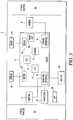
- FIG. 1in accordance with the conventional processes for manufacturing an ASIC chip, representative electronic components required for the operation of a pulse oximeter are formed or integrated into the ASIC circuit 8. These include a processor 10, a memory 12, an electronic circuit 14 specifically designed for performing the oximetry functions, an emitter interface circuit 16, a sensor interface circuit 18, a display driver 20 and an alarm driver 22.
- ASIC circuit 8is presumed to be in the form of a thin chip that may be flexible and/or is mounted or embedded in a particular layer of the patch, as will be discussed in more detail, infra.
- the algorithm for performing the SpO2 analysismay be that described in U.S. patent 5,558,096 , assigned to the assignee of the instant invention.
- the disclosure of the '096 patentis incorporated by reference herein.
- Other algorithms or software that may be needed for effecting the operation of emitter 4 and sensor 6 in a conventional waymay also be stored in memory 12.
- the software for operating other components or electronics that are to be discussed hereinbelowmay also be stored in memory 12.
- a display 24, an alarm 26, and a power source in the form of a battery 28may be a thin membrane LCD display while alarm 26 may be a piezoelectric transducer that conceivably could be integrated as a separate electronic component mounted on patch 2.
- Battery 28, for the instant invention oximetermay be a conventional thin plate battery or a fuel cell battery that self activates when the patch is removed from its sterile packaging.
- a chemical light source that also self activates when the patch is removed from its sterile package, or having its adhesive backing strip removed,may be used as an illumination source for display 24. Using a chemical illumination source would extend the battery life. Self activation would eliminate the need for an "on" switch. Further, the illumination source could be automated to sense ambient lighting conditions to determine the need for the illumination source, thereby conserving battery power when self- illumination is not required.
- the duration of the chemical lightmay be adjusted to mirror the life of the battery.
- Attach portions 30 and 32may in fact be an adhesive layer at the face of the patch that comes into contact with the patient for adhesively attaching the patch to the patient.
- Attach portions 30 and 32may also be made of velcro, so that the patch, in the form a bandage, may be wrapped around a digit or an earlobe of the patient.
- Other types of attach mechanismssuch as clasps or snaps may also be used. This is particularly true insofar as emitter 4 and sensor 6, as shown in the Fig. 1 embodiment, are arranged or oriented to work cooperatively in a transmissive mode when the patch oximeter is wrapped around the digit, earlobe or bridge of the nose of the patient.
- Fig. 2has the same components as those shown in Fig. 1 .
- the same components in Fig. 2as well as those same components in the other figures to be discussed, are accordingly labeled the same.
- the one difference between the patch oximeter shown in Fig. 2 from that shown in Fig. 1is the placement of the emitter 4 and sensor 6 on the patch.
- emitter 4 and sensor 6are mounted in defined proximity to each other on the patch, so as to enable the patch oximeter to measure the SpO2 of the patient reflectively.
- the reflective mode patch oximeter of Fig. 2is best adapted to attach to the forehead, or another substantially flat skin surface, of the patient.
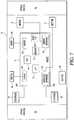
- Fig. 3shows another embodiment of the instant invention in which, in addition to having all of the components of the previously discussed embodiments, the patch oximeter further has electronic components mounted thereto that enable it to operate as a wireless patch oximeter.
- a transmitter or transceiver 34is added to the electronics layer of the patch, and an antenna 36 coupled to transceiver 34 provides the means by which signals may be transmitted and/or transceived to or from the patch oximeter.
- electronics in the form of a transmission circuit 38is added to the electronics layer of the patch, either as a separate circuit or integrated to the ASIC circuit 8.
- the functionalities of the transceiver 34 and its associate transmission circuit 38may be gleaned from assignee's U.S. patent 6,731,962 , the disclosure of which being incorporated by reference herein.
- the patch oximeterAs the patch oximeter is equipped with a transceiver 34, not only could the patch oximeter transmit information to a remote device, it could likewise receive information from the remote device.
- the patch oximetermay ordinarily be in a sleep mode, and may be awakened by a signal from the remote device that awakens the patch oximeter to begin its monitoring or measurement.
- the last transmission of the patch oximetermay not have been correctly received by the remote device and hence the remote device could request the patch oximeter to resend the data.
- the light emitter 4 and sensor 6 of the wireless patch oximeter embodimentare shown to be arranged for operating in the transmissive mode, it should be appreciated that the wireless patch oximeter could likewise work in the reflective mode by simply rearranging the respective positions of emitter 4 and sensor 6 as shown per the Fig. 2 embodiment.
- the patch oximeter of Fig. 3is capable of at least transmitting the calculated SpO2 of the patient to a remote device, for example a monitor system such as the assignee's Vital Sign monitor equipped with the appropriate telecommunication transceiver such as for example an RF transmitter with its RF link, for displaying and/or recording the patient's SpO2 at the remote device.
- a monitor systemsuch as the assignee's Vital Sign monitor equipped with the appropriate telecommunication transceiver such as for example an RF transmitter with its RF link, for displaying and/or recording the patient's SpO2 at the remote device.
- transceiver 34being integrated to the patch oximeter, the information or data acquired by sensor 6, or by the to be discussed electrodes added to the patch oximeter, may be transmitted to a similar wireless patch oximeter, so that a mini telecommunication network may be established among a plurality of wireless patch oximeters to enable the medical personnel to closely monitor the different physiological parameters of the patient. Such monitoring will be discussed in more detail
- Fig. 4illustrates another embodiment of the instant invention in which the battery power source has been removed from the patch oximeter. Instead, power for the patch oximeter is obtained remotely by the incorporation of an antenna 40 and a coil 42. Antenna 40 is optional, as coil 42 is the component that allows the patch oximeter to receive power from a remote power source.
- the electronics that may be required to provide the functionalities to retrieve power remotelyis added to the patch by way of a remote power circuit 44.
- the operation of the remote power grabis similar to the conventional RFID (radio frequency identification) technology that is being used for identifying goods.
- RFIDradio frequency identification
- the electronic circuit that operates to trigger the alarmgets its power from a remote power source.
- the same scenariomay be used with the Fig. 4 wireless patch oximeter, with the proviso that the power required for operating the patch oximeter embodiment such as that shown in Fig. 4 be increased by at least two fold, so that a sufficient level of power is provided for the operation of emitter 4.
- Fig. 4even though display 24 and alarm 26 remain, it should be appreciated that those components may not necessarily be needed, especially when there is no need for the patient to look at the display, as for example when the patient wears the patch oximeter because she is in a sleep study involving for example sleep apnea, whereby the readings from the patient are displayed remotely on a remote monitor.
- a patch oximeter that does not include the display and alarm components, and their respective drivers,is shown in Fig. 5 .
- the patch oximeteris adapted to work in both the transmissive mode and the reflective mode, irrespective of how the emitter 4 and sensor 6 are shown to be positioned in the figures.
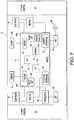
- FIG. 6Another aspect of the instant invention is illustrated by the block diagram of the strip or bandage shown in Fig. 6 .
- the disposable patch oximeter of Fig. 6has added thereto two electrodes 44 and 46, and their respective interface circuits 44a and 44b, which may be integrated to the ASIC circuit 8, or as additional electronics mounted separately to the electronics layer of the patch 2.
- Additional electronics represented by electrode circuit 48may also be integrated to the ASIC circuit 8, or be mounted as an individual component on the electronics layer of the patch 2.
- electrodes 44 and 46are conventional bioelectric electrodes (without limitation for example silver-silver chloride, possibly pre-jelled electrodes) that, when positioned at a distance from each other (or formed concentrically), are able to measure additional physiological parameters of the patient, such as for example EKG, ECG, etc.
- EKG and ECGare well known physiological parameters associated with the electrical stimuli of the heart.
- the addition of electrodes to measure bioelectric eventspermits the determination of time differences between the ECG QRS complex and the patient's plethysmograph waveform which has been shown to correlate withnon-invasive blood pressure (NIBP).
- NIBPnon-invasive blood pressure
- an electrode or sensor in the form of a temperature probemay also be added to the patch, along with the appropriate electronics, to measure the temperature of the patient.
- a temperature probein addition to SpO2 and heart rate, other types of physiological parameters such as temperature, blood pressure, in the form of a non-invasive blood pressure (NIBP) could be continuously monitored, or obtained.
- NIBPnon-invasive blood pressure
- Fig. 7shows in block diagram format the possible different placements of electrodes 44 and 46, as well as the placement of emitter 4 and sensor 6 on the patch, in the event that the SpO2 to be obtained from the patient needs to be done on the patient's forehead, or another substantially flat surface of the patient, via the reflective mode.
- Fig. 8shows a wireless patch oximeter with ECG electrodes 44 and 46, and the electrode circuit 48 for acquiring the data measured by the electrodes.
- the electrode circuit 48for acquiring the data measured by the electrodes.
- data relating to other physiological parameters of the patient, as collected by electrodes 44 and 46may likewise be transmitted to a remote device, such as the previously mentioned Vital Signs monitor for display and/or recording.
- a remote devicesuch as the previously mentioned Vital Signs monitor for display and/or recording.
- Fig. 9illustrates in block diagram format the embodiment of the wireless patch oximeter of the instant invention where SpO2, heart rate and other physiological parameters may be measured from the patient.
- the Fig. 9 embodimentis similar to the Fig. 4 embodiment in that the power for the operation of the patch oximeter is retrieved from a remote power source when the patch oximeter comes within a given distance from the remote power source.
- the power for the operation of the patch oximeteris retrieved from a remote power source when the patch oximeter comes within a given distance from the remote power source.
- the patch oximeter attached to the patientmay not be activated until the patient gets within a given distance from the remote power source, in which case the electronic circuit, for example circuit 14, would awake to activate the remaining electronic circuits to perform their respective functions, and power up emitter 4. If sufficient power is accessed from the remote power source, the patient may also be able to view, per display 24, her SpO2 and heart rate, as well as the ECG and possibly a strength bar graph. Membrane switches, not shown, may be provided on the top layer of the patch to activate/deactivate alarm 26, and/or display 24.
- Fig. 10shows the patch oximeter of Fig. 9 but without any display or alarm.
- Such wireless oximeter/electrode combination patchmay be used where there is no need for the patient to view any readings or hear any alarms, as for example in the above-discussed sleep apnea study where the patient is asleep while measurement of the various physiological parameters of the patient takes place.
- Fig. 11is an illustration of the patch oximeter of the instant invention in the form of a bandage. As shown, display 24 of the bandage shows both the heart rate and the SpO2 of the patient.
- Fig. 12shows in a cross-sectional view the different layers of the patch of the oximeter of the instant invention. It should be appreciate that the various layers shown in Fig. 2 are not drawn to scale or in proportion to their respective thicknesses.
- the layer 52 that comes into contact with the patientis an adhesive layer.
- adhesive layer 52is prevented from being exposed to the environment by the peel off sheet or paper 50.
- a foam layer 54that provides comfort to the patient and also compensates for movements of the patient.
- a barrier layer 56which may be a plastic sheet or a polyimide sheet that acts as a moisture resistant and electrically insulation layer.
- barrier layer 56 on its lower side and another barrier layer 58 on its upper sideis the electronics layer 60 whereby the various electronic components including the ASIC circuit and the other circuits mentioned previously are embedded or mounted.
- the electrical interconnections among the various components and/or the ASIC circuit with emitter 4 and sensor 6are represented by the electronics layer 60 being in direct contact therewith.
- Emitter 4 and sensor 6each are shown to be extending from electronics layer 60 to be flush with, or slightly above, adhesive layer 52.
- the optional electrodes 44 and 46likewise are shown to extend from electronics layer 60 to adhesive layer 52. Although shown as being flush with adhesive layer 52, to operate more efficiently, the surfaces of the electrodes may in fact extend slightly beyond adhesive layer 52 and may be pre-gelled. In any event, each of the contact surfaces of emitter 4, sensor 6 and electrodes 44,46 are protected by peel off sheet 50.
- the electronics layeris sandwiched by two protective barrier layers 56 and 58.
- display 24extends from electronics layer 60 to be flush with the top surface with barrier layer 58.
- display 24may be mounted within electronics layer 60, as barrier layer 58, similar to barrier layer 56, may be a clear plastic moisture resistant and electrically insulating sheet that allows the display to be seen from the top of the patch.
- switches 61that may be a part of barrier layer 58 or be embedded in electronics layer 60.
- Barrier layer 58is topped with a protective membrane layer 62 that may have graphics printed thereon and appropriate clear window areas, so that display 24 may be viewed, per shown in Fig. 11 .
- the patientcan readily determine which switch to push in order to activate/deactivate the operation of those components to which the caregiver/patient is allowed to control, for example optional display 24 and/or alarm 26, which are not shown in the Fig. 12 patch layers.
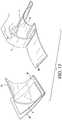
- Fig. 13illustrates the packaging of the patch oximeter of the instant invention.
- Patch 2may be housed or stored in a package 63 that includes a clear top wrap 64 and a bottom wrap 66.
- Bottom wrap 66may be the peel off sheet 50 shown in Fig. 12 which may have the additional function of activating battery 28 when peeled off, if battery 28 is a fuel cell type battery that utilizes the zinc/air chemistry to operate.
- battery 28when stored in air tight environment, is inactive. But as soon as the sheet, for example 50, is peeled off from the patch, the battery becomes activated due to its exposure to air. This feature is advantageous in that it allows the patch oximeter to be stored for an extended length of time.
- Battery 28may also be a photovoltaic type battery in which power is supplied when the battery is exposed to light. When a photovoltaic battery is used, the placement of the battery on the patch is such that light is allowed to reach the photovoltaic cell via a clear window provided at the membrane layer 62.
- the peeling off of sheet 50 from the adhesive layermay also be used to activate the above-mentioned chemical light source, which presumably begins its chemical reaction when exposed to air or light.
- Fig. 14illustrates the telecommunication functionalities of the wireless embodiment of the patch oximeter of the instant invention.
- Patch oximeter 2retrieves power from a remote power source 68 when it is within a given distance therefrom (for the non-self powered wireless patch oximeter), and then transmits data collected from the patient and/or the calculated SpO2 to the monitor system 70 via the latter's receiver 72.
- the operation of the transmission of the data from patch oximeter 2 to the monitor systemis similar to that given in the above incorporated by reference '962 patent, which discloses the use of an RF link for transmitting data packets from the oximeter to the monitor system 70, and the unpacking of the packets by the monitor system 70.
- Fig. 15illustrates the use of a plurality of patch oximeters of the instant invention, in their wireless form, for transmitting information to a remote device for informing the medical personnel whether the patient is in shock.
- a patch oximeter 2is attached to the forehead of patient 74.
- Another patch oximeter 2'is attached to an extremity, for example a finger digit of the patient.
- the respective rates of blood perfusion at the forehead and at the extremity of the patientare also measured and the differential between the measurements is determined. This is important insofar as when a person goes into shock, for example hypovolemic shock, the extremities of the patient would tend to shut down the blood perfusion before the brain.
- septic or systolic shockmay also be measured.
- perfusionis conventionally represented by an index, calculated as the ratio of the peak-to-peak red transmission signal to the peak-to-peak infrared transmission signal. See for example U.S. patent publication 2003/0236452 , the disclosure of which being incorporated by reference herein.
- a flow diagram illustrating the method of determining whether a patient is in shock or at the onset of shockis provided in the flow chart of Fig. 16 .
- the process of determining shock in the patientbegins with the attachment of a plurality of the patch oximeters of the instant invention to the patient, per step 76.
- Perfusion measurementsare obtained from the oximeter per step 78.
- a determinationis made, per step 80, on whether there is a perfusion differential between the measurements at for instance the forehead and an extremity of the patient. If there is a differential, such differential is compared with a predetermined condition range, for example a predefined 1-10, that has been pre-calibrated to determine whether the patient is okay, at the onset of shock, or already in shock.
- the processreturns to the monitor phase whereby the differences in the measurements between the at least two areas of the patient where the patch oximeters of the instant invention are attached are continuously monitored and calculated.
- the patch oximetersonce used, are disposed of.
Landscapes
- Health & Medical Sciences (AREA)
- Life Sciences & Earth Sciences (AREA)
- Physics & Mathematics (AREA)
- Engineering & Computer Science (AREA)
- Medical Informatics (AREA)
- Animal Behavior & Ethology (AREA)
- Pathology (AREA)
- Veterinary Medicine (AREA)
- Biomedical Technology (AREA)
- Heart & Thoracic Surgery (AREA)
- Public Health (AREA)
- Molecular Biology (AREA)
- Surgery (AREA)
- Biophysics (AREA)
- General Health & Medical Sciences (AREA)
- Spectroscopy & Molecular Physics (AREA)
- Optics & Photonics (AREA)
- Computer Networks & Wireless Communication (AREA)
- Hematology (AREA)
- Measurement Of The Respiration, Hearing Ability, Form, And Blood Characteristics Of Living Organisms (AREA)
- Investigating Or Analysing Materials By Optical Means (AREA)
Description
- The present invention relates to oximeters and more particularly to a single use oximeter that is self-contained in a patch, such as for example a self-adhesive bandage. The present invention further relates to a disposable patch oximeter having telecommunication capabilities.
- Oximeters are well known. Prior to the instant invention, self-contained oximeters come in the form of bulky housings that clip onto the finger of a patient, such as that disclosed in
U.S. patent 5,792,052 . Another example of a self-contained oximeter is that disclosed inU.S. patent 6,654,621 , assigned to the assignee of the instant application. In these prior art self-contained finger oximeters, electronics are contained in housings that pivotally grasp the finger of a patient ('052 patent) or a housing that forms an opening to which the finger of the patient is inserted ('621 patent). Once the oxygen saturation level of the patient is determined, these finger oximeters may be removed from the patient and used on other patients, as these finger oximeters are reusable devices. - There is also in the market a bandage that has embedded therein the light emitter and sensor of an oximeter. The electronics for operating the light emitter and sensor and to which the bandage is connected is located remotely from the bandage. This device is disclosed in
U.S. patents 6,735,459 ,6,721,585 ,6,684,091 ,6,519,487 ,6,343,224 ,6,321,100 and6,144,868 . Only the bandage is disposable in this device. US 5,511,553 discloses a device, system and method for monitoring continuously and simultaneously multiple physiological parameters from a patient, comprising a precordial strip-patch having first and second surfaces and multi-layer flexible structure permitting telemetering data.US 2005/131,288 discloses an apparatus and method for the transduction, acquisition, and processing of physiologic variables. The apparatus is a self-contained, patient-worn device consisting of a flexible substrate, a transduction means, a power generation means, and a signal acquisition and processing means, and a data transmission means.US 5,957,854 discloses a medical diagnosis and monitoring equipment has wireless electrodes, which are attached to the surface of the skin of the patient.US 2002/107,436 discloses a skin patch includes first and second layers of material and a telesensor sandwiched between the first and second layers.DE100 15 928 A1 discloses a carrier of a medicament or some other active substance administrable to its recipient via skin comprising a protective layer which is provided with an electric conductor strip running over a separable section of the protective layer.- A first aspect of the invention provides an apparatus, as defined in claim 1.
- The present invention is a self-contained, fully disposable, single use pulse oximeter that activates when the backing paper for its adhesive is peeled off. All of the components for the oximeter are mounted, integrated, or embedded to a multi-layered patch, or bandage. In addition to the light or radiation emitter that outputs a multifrequency light to the patient, be it the digit or the forehead of the patient, and the sensor or detector that senses the light passing through, or reflecting from, the patient for obtaining data from the patient and then calculating the oxygen saturation level of blood (SpO2) from the acquired data, the other components for the pulse oximeter are also mounted to the patch. This includes the oximetry circuitry, an optional display, an optional alarm possibly in the form of a piezoelectric transducer (audible) and/or an optical indicator on the display (visual) and the power source. The circuitry may be integrated to an application specific integrated circuit (ASIC) platform or chip, and is embedded to a layer of the bandage that is protected by at least two thin barrier layers that are immune to moisture and prevent the ASIC from being exposed to the environment. The power source may be a thin conventional button battery, or a fuel cell battery, that may also be embedded in the same layer as the ASIC chip. The same layer of the bandage may also include the optional display and alarm. Alternatively, the display and the alarm may be formed at a layer of the bandage that is above the ASIC platform layer and beneath a protective membrane layer that may include preprinted graphics. Membrane switches may also be provided under the protective membrane to provide the user the capability to activate a limited number of functions, as for example turning on/off the alarm and/or display.
- The bandage is a sterile bandage with a peel off sheet covering its lower most adhesive layer that allows the bandage to be removably attached to the patient. To provide additional sterility, the bandage may be stored or housed in a sterile package that may have a removable cover.
- The light emitter and detector are positioned onto the patch depending on whether the patch is to be used in a transmissive mode in which the patch, or bandage, is wrapped around a digit or an earlobe of a patient, or in a reflective mode whereby the patch is adhesively secured to the forehead, or another substantially flat surface, of the patient.
- Telecommunication capabilities are also added to the disposable patch oximeter of the instant invention. For the wireless patch oximeter, a transceiver is mounted to, or embedded in, the patch or bandage. The circuitry required for transmitting or transceiving the signals to/from the patch oximeter are either added or integrated to the ASIC chip, or is added as a separate circuit to the electronics layer of the patch.
- For the patch oximeter of the instant invention, the most convenient way in which to attach the bandage to the patient is by means of an adhesive layer, as is conventionally done in conventional bandages that are used to cover cuts on an individual. However, other attachment mechanisms may also be used for the instant invention patch oximeter or bandage. Such attachment mechanisms may include for example velcro or snaps that would allow the bandage to be securely attached to the patient. Instead of a full layer of adhesive, only portions of the lower most layer of the bandage need to be provided with the adhesive in order to enable the bandage to be removably attachable to a patient.
- In addition to being able to wirelessly communicate with a host monitor system where at least the patient's oxygen saturation level of arterial blood (SpO2) is remotely monitored, each patch oximeter may also be able to communicate with another similar patch oximeter that is attached to another location on the patient. With at least two oximeters attached to the patient, a differential of the SpO2 of the patient may be obtained, so that a hypovolemic shock determination could be made on the patient, i.e., whether the patient is just bleeding, on the verge of going into shock, or in fact is in shock.
- Electrodes may also be added to the bandage oximeter of the instant invention, so that physiological parameters other than the oxygen saturation level of the arterial blood of the patient, for example EEG, ECG, EKG, etc., may be obtained from the patient, at the same time that the SpO2 is being obtained from the patient. For measuring additional physiological parameters from the patient, additional electronics that enable the patch oximeter to perform additional measurement functions are either integrated to the ASIC circuit, or mounted to the electronics layer of the patch as separate additional circuits.
- With respect to the wireless patch oximeter, instead of embedding the power source onto the patch, a power source remote from the patch, which would supply power to the patch when the patch comes within a predetermined or given distance from the remote power source, may be used. For this radio frequency identification (RFId) equipped embodiment, an antenna coil, as well as an RF power receiver, are added to the oximeter patch, so that power may be retrieved from the remote power source when the bandage comes within communication distance from the remote power source. For this embodiment, and possibly other wireless embodiments of the inventive patch oximeter, the display and/or the alarm may not be needed on the patch.
- The wireless one-piece disposable oximeter of the instant invention is a one-piece disposable patch that is adapted to be attached to a patient for measuring at the oxygen saturation level of arterial blood of the patient. The wireless patch oximeter includes a light emitter mounted to the patch, a light detector mounted to the patch to detect the light from the light emitter that passes through the patient, or reflected back from the patient, so that data relating to at least the oxygen saturation level of the arterial blood of the patient may be acquired, an electronic circuit mounted to the patch for effecting operation of the light emitter and the light detector, and to calculate from the data acquired the oxygen saturation level of arterial blood of the patient, a transceiver mounted to the patch to at least transmit the calculated oxygen saturation level of arterial blood or data acquired of the patient to a remote device, and an attachment mechanism at the patch that enables the patch to be removably attached to the patient.
- The oximeter of the instant invention furthermore includes a patch adaptable to be attached to the patient, a light emitter and a light detector each mounted to the patch, an electronic circuit mounted to the patch for effecting operation of the light emitter and the light detector, and to calculate from the data acquired by the light detector due to the light from the light emitter that passes the patient it senses, at least the oxygen saturation level of the arterial blood of the patient, a transceiver mounted to the patch to enable the patch to at least transmit the signal representing the oxygen saturation level of arterial blood of the patient or the data acquired by the light detector to a remote device, and means provided at the patch to enable the patch to be removably attached to the patient.
- The instant invention will become apparent and will best be understood by reference to the following description of the invention taken in conjunction with the accompanying drawings, wherein:
Fig. 1 is a block diagram of the oximeter patch or bandage of the instant invention, with the light emitter and the light detector being positioned on the patch to operate in a transmissive mode to measure the oxygen saturation level of arterial blood of the patient when the patch is wrapped around a digit or an earlobe of the patient;Fig. 2 is a block diagram of the patch oximeter of the instant invention in which the orientation of the light detector and light emitter as mounted to the patch is such that the oximeter is adaptable to operate in a reflective mode, with the patch being adhesively attached to the forehead, or another substantially flat surface, of the patient;Fig. 3 is a block diagram of the patch oximeter of the instant invention in which a transmitter or transceiver, and appropriate electronics for operating the same, are added to the patch to enable the patch oximeter to wirelessly communicate with a remote device;Fig. 4 is a block diagram of a wireless patch oximeter with no power source provided on the patch, but with an antenna and a coil added to the patch to retrieve and utilize power provided from a remote power source;Fig. 5 is a different embodiment of theFig. 4 wireless patch oximeter in which the display and alarm, in addition to their respective drivers, are removed from the patch;Fig. 6 is a block diagram of a patch oximeter that has at least two electrodes added to the patch to enable the patch oximeter to obtain from the patient at least one other physiological parameter in addition to the SpO2, which is obtained in a transmissive mode;Fig. 7 is a block diagram showing a patch oximeter that is the same as that shown inFig. 6 , but with the light emitter and the light detector oriented to operate in a reflective mode;Fig. 8 is a block diagram illustrating a wireless patch oximeter configured with electrodes to obtain additional physiological parameters of the patient;Fig. 9 is a block diagram of a wireless patch oximeter with electrodes mounted to the patch that is powered by a remote power source;Fig. 10 is a block diagram of the patch oximeter ofFig. 9 , but with the display and alarms removed;Fig. 11 is an illustrated top view of an exemplar patch oximeter of the instant invention;Fig. 12 is a cross-sectional view of the different layers of the patch or bandage strip of the patch oximeter of the instant invention;Fig. 13 illustrates an exemplar sterile package of the disposable oximeter of the instant invention, and the removal of the oximeter from the sterile package;Fig. 14 is a simplified diagram of a patch oximeter of the instant invention communicating with a remote monitoring system;Fig. 15 is a simplified drawing showing a plurality of patch oximeters of the instant invention attached to different areas of a patient to provide a differential measurement of the SpO2 or perfusion of the patient, which may be indicative of whether the patient is in shock, to a remote monitor system; andFig. 16 is a flow diagram illustrating the processes of determining whether the patient shown inFig. 15 is in shock.- With reference to
Fig. 1 , aflexible patch 2, in the form of a bandage or strip, has mounted thereto a light orradiation emitter 4 and a photodetector orsensor 6. As is well known,light emitter 4 may be made up of a number of LEDs each outputting a light at a different frequency, so thatemitter 4 in essence outputs a multifrequency light to a part of the patient, be that part a digit, the bridge of the nose, an earlobe, the forehead or some other body part of the patient.Photodetector 6 then senses or detects the light that passes through the patient as data obtained from the patient. - Also mounted onto
patch 2 is an application specific integrated circuit (ASIC) 8, possibly in the form of a flexible circuit platform or chip, in which the various electronic components for controllingemitter 4 andsensor 6, as well as for calculating from the data collected or acquired bysensor 6 at least the oxygen saturation level of arterial blood (SpO2) and the heart rate of the patient. As shown inFig. 1 , in accordance with the conventional processes for manufacturing an ASIC chip, representative electronic components required for the operation of a pulse oximeter are formed or integrated into theASIC circuit 8. These include aprocessor 10, amemory 12, anelectronic circuit 14 specifically designed for performing the oximetry functions, anemitter interface circuit 16, asensor interface circuit 18, adisplay driver 20 and analarm driver 22. Other electronics that may also be integrated to theASIC circuit 8 are not shown for the sake of simplicity. For the oximeter embodiments discussed herein,ASIC circuit 8 is presumed to be in the form of a thin chip that may be flexible and/or is mounted or embedded in a particular layer of the patch, as will be discussed in more detail,infra. - The algorithm for performing the SpO2 analysis may be that described in
U.S. patent 5,558,096 , assigned to the assignee of the instant invention. The disclosure of the '096 patent is incorporated by reference herein. Other algorithms or software that may be needed for effecting the operation ofemitter 4 andsensor 6 in a conventional way may also be stored inmemory 12. Moreover, the software for operating other components or electronics that are to be discussed hereinbelow may also be stored inmemory 12. - For the oximeter shown in
Fig. 1 , also mounted to thepatch 2 is adisplay 24, analarm 26, and a power source in the form of abattery 28.Display 24 may be a thin membrane LCD display whilealarm 26 may be a piezoelectric transducer that conceivably could be integrated as a separate electronic component mounted onpatch 2.Battery 28, for the instant invention oximeter, may be a conventional thin plate battery or a fuel cell battery that self activates when the patch is removed from its sterile packaging. A chemical light source that also self activates when the patch is removed from its sterile package, or having its adhesive backing strip removed, may be used as an illumination source fordisplay 24. Using a chemical illumination source would extend the battery life. Self activation would eliminate the need for an "on" switch. Further, the illumination source could be automated to sense ambient lighting conditions to determine the need for the illumination source, thereby conserving battery power when self- illumination is not required. For the instant invention, the duration of the chemical light may be adjusted to mirror the life of the battery. - For illustration purposes, also provided at
patch 2 are attachedportions portions emitter 4 andsensor 6, as shown in theFig. 1 embodiment, are arranged or oriented to work cooperatively in a transmissive mode when the patch oximeter is wrapped around the digit, earlobe or bridge of the nose of the patient. A more detailed discussion of the various layers of the oximeter patch will be given below with respect to the discussion ofFig. 12 . Fig. 2 has the same components as those shown inFig. 1 . The same components inFig. 2 , as well as those same components in the other figures to be discussed, are accordingly labeled the same. The one difference between the patch oximeter shown inFig. 2 from that shown inFig. 1 is the placement of theemitter 4 andsensor 6 on the patch. As shown,emitter 4 andsensor 6 are mounted in defined proximity to each other on the patch, so as to enable the patch oximeter to measure the SpO2 of the patient reflectively. Thus, the reflective mode patch oximeter ofFig. 2 is best adapted to attach to the forehead, or another substantially flat skin surface, of the patient.Fig. 3 shows another embodiment of the instant invention in which, in addition to having all of the components of the previously discussed embodiments, the patch oximeter further has electronic components mounted thereto that enable it to operate as a wireless patch oximeter. In particular, a transmitter ortransceiver 34 is added to the electronics layer of the patch, and anantenna 36 coupled totransceiver 34 provides the means by which signals may be transmitted and/or transceived to or from the patch oximeter. To provide additional functionalities that are required for the operation of thetransceiver 34, electronics in the form of atransmission circuit 38 is added to the electronics layer of the patch, either as a separate circuit or integrated to theASIC circuit 8. The functionalities of thetransceiver 34 and itsassociate transmission circuit 38 may be gleaned from assignee'sU.S. patent 6,731,962 , the disclosure of which being incorporated by reference herein.- As the patch oximeter is equipped with a
transceiver 34, not only could the patch oximeter transmit information to a remote device, it could likewise receive information from the remote device. For example the patch oximeter may ordinarily be in a sleep mode, and may be awakened by a signal from the remote device that awakens the patch oximeter to begin its monitoring or measurement. By way of another example, the last transmission of the patch oximeter may not have been correctly received by the remote device and hence the remote device could request the patch oximeter to resend the data. - Even though the
light emitter 4 andsensor 6 of the wireless patch oximeter embodiment are shown to be arranged for operating in the transmissive mode, it should be appreciated that the wireless patch oximeter could likewise work in the reflective mode by simply rearranging the respective positions ofemitter 4 andsensor 6 as shown per theFig. 2 embodiment. - With the wireless functionalities, the patch oximeter of
Fig. 3 is capable of at least transmitting the calculated SpO2 of the patient to a remote device, for example a monitor system such as the assignee's Vital Sign monitor equipped with the appropriate telecommunication transceiver such as for example an RF transmitter with its RF link, for displaying and/or recording the patient's SpO2 at the remote device. Withtransceiver 34 being integrated to the patch oximeter, the information or data acquired bysensor 6, or by the to be discussed electrodes added to the patch oximeter, may be transmitted to a similar wireless patch oximeter, so that a mini telecommunication network may be established among a plurality of wireless patch oximeters to enable the medical personnel to closely monitor the different physiological parameters of the patient. Such monitoring will be discussed in more detail,infra, with respect toFig. 15 . Fig. 4 illustrates another embodiment of the instant invention in which the battery power source has been removed from the patch oximeter. Instead, power for the patch oximeter is obtained remotely by the incorporation of anantenna 40 and acoil 42.Antenna 40 is optional, ascoil 42 is the component that allows the patch oximeter to receive power from a remote power source. The electronics that may be required to provide the functionalities to retrieve power remotely is added to the patch by way of aremote power circuit 44. The operation of the remote power grab is similar to the conventional RFID (radio frequency identification) technology that is being used for identifying goods. One example of the use of such RFID technology is in the miniaturized electronic circuit labels that are placed on items, for example, that would identify the items when they are sold. If perchance the customer had not paid for an item, when the item is taken past the cash register or out the store, an alarm is triggered. The electronic circuit that operates to trigger the alarm gets its power from a remote power source. The same scenario may be used with theFig. 4 wireless patch oximeter, with the proviso that the power required for operating the patch oximeter embodiment such as that shown inFig. 4 be increased by at least two fold, so that a sufficient level of power is provided for the operation ofemitter 4.- For the
Fig. 4 embodiment, even thoughdisplay 24 andalarm 26 remain, it should be appreciated that those components may not necessarily be needed, especially when there is no need for the patient to look at the display, as for example when the patient wears the patch oximeter because she is in a sleep study involving for example sleep apnea, whereby the readings from the patient are displayed remotely on a remote monitor. A patch oximeter that does not include the display and alarm components, and their respective drivers, is shown inFig. 5 . As was mentioned previously, for all of the disclosed embodiments, it is assumed that the patch oximeter is adapted to work in both the transmissive mode and the reflective mode, irrespective of how theemitter 4 andsensor 6 are shown to be positioned in the figures. - Another aspect of the instant invention is illustrated by the block diagram of the strip or bandage shown in
Fig. 6 . As shown, the disposable patch oximeter ofFig. 6 has added thereto twoelectrodes respective interface circuits 44a and 44b, which may be integrated to theASIC circuit 8, or as additional electronics mounted separately to the electronics layer of thepatch 2. Additional electronics represented byelectrode circuit 48 may also be integrated to theASIC circuit 8, or be mounted as an individual component on the electronics layer of thepatch 2. In either event,electrodes - In addition to the above mentioned physiological parameters that involve the pulse, the heart rate and the SpO2 of the patient, an electrode or sensor in the form of a temperature probe may also be added to the patch, along with the appropriate electronics, to measure the temperature of the patient. Thus, with the patch oximeter of
Fig. 6 , in addition to SpO2 and heart rate, other types of physiological parameters such as temperature, blood pressure, in the form of a non-invasive blood pressure (NIBP) could be continuously monitored, or obtained. Fig. 7 shows in block diagram format the possible different placements ofelectrodes emitter 4 andsensor 6 on the patch, in the event that the SpO2 to be obtained from the patient needs to be done on the patient's forehead, or another substantially flat surface of the patient, via the reflective mode.Fig. 8 shows a wireless patch oximeter withECG electrodes electrode circuit 48 for acquiring the data measured by the electrodes. For theFig. 8 embodiment, in addition to the SpO2 and data collected bysensor 6 for calculating at least the SpO2, data relating to other physiological parameters of the patient, as collected byelectrodes separate telecommunications circuit 38 andelectrode circuit 48 are shown, those circuits may in fact be incorporated into the mainelectronic circuit 14 of theASIC circuit 8 mounted to the electronics layer ofpatch 2.Fig. 9 illustrates in block diagram format the embodiment of the wireless patch oximeter of the instant invention where SpO2, heart rate and other physiological parameters may be measured from the patient. TheFig. 9 embodiment is similar to theFig. 4 embodiment in that the power for the operation of the patch oximeter is retrieved from a remote power source when the patch oximeter comes within a given distance from the remote power source. Thus, for the patch oximeter ofFig. 9 , as well as for the remote power access patch oximeters described inFigs. 4 and5 , the patch oximeter attached to the patient may not be activated until the patient gets within a given distance from the remote power source, in which case the electronic circuit, forexample circuit 14, would awake to activate the remaining electronic circuits to perform their respective functions, and power upemitter 4. If sufficient power is accessed from the remote power source, the patient may also be able to view, perdisplay 24, her SpO2 and heart rate, as well as the ECG and possibly a strength bar graph. Membrane switches, not shown, may be provided on the top layer of the patch to activate/deactivatealarm 26, and/ordisplay 24.Fig. 10 shows the patch oximeter ofFig. 9 but without any display or alarm. Such wireless oximeter/electrode combination patch may be used where there is no need for the patient to view any readings or hear any alarms, as for example in the above-discussed sleep apnea study where the patient is asleep while measurement of the various physiological parameters of the patient takes place.Fig. 11 is an illustration of the patch oximeter of the instant invention in the form of a bandage. As shown,display 24 of the bandage shows both the heart rate and the SpO2 of the patient.Fig. 12 shows in a cross-sectional view the different layers of the patch of the oximeter of the instant invention. It should be appreciate that the various layers shown inFig. 2 are not drawn to scale or in proportion to their respective thicknesses. As shown, starting with the peel offsheet 50, thelayer 52 that comes into contact with the patient is an adhesive layer. In any event,adhesive layer 52 is prevented from being exposed to the environment by the peel off sheet orpaper 50. Aboveadhesive layer 52 is afoam layer 54 that provides comfort to the patient and also compensates for movements of the patient. On top offoam layer 54 is abarrier layer 56, which may be a plastic sheet or a polyimide sheet that acts as a moisture resistant and electrically insulation layer.- Protected by
barrier layer 56 on its lower side and anotherbarrier layer 58 on its upper side is theelectronics layer 60 whereby the various electronic components including the ASIC circuit and the other circuits mentioned previously are embedded or mounted. The electrical interconnections among the various components and/or the ASIC circuit withemitter 4 andsensor 6 are represented by theelectronics layer 60 being in direct contact therewith.Emitter 4 andsensor 6 each are shown to be extending fromelectronics layer 60 to be flush with, or slightly above,adhesive layer 52. Theoptional electrodes electronics layer 60 toadhesive layer 52. Although shown as being flush withadhesive layer 52, to operate more efficiently, the surfaces of the electrodes may in fact extend slightly beyondadhesive layer 52 and may be pre-gelled. In any event, each of the contact surfaces ofemitter 4,sensor 6 andelectrodes sheet 50. - As noted above, the electronics layer is sandwiched by two protective barrier layers 56 and 58. As shown in
Fig. 12 ,display 24 extends fromelectronics layer 60 to be flush with the top surface withbarrier layer 58. Alternatively,display 24 may be mounted withinelectronics layer 60, asbarrier layer 58, similar tobarrier layer 56, may be a clear plastic moisture resistant and electrically insulating sheet that allows the display to be seen from the top of the patch. Also shown are optional switches 61 that may be a part ofbarrier layer 58 or be embedded inelectronics layer 60.Barrier layer 58 is topped with aprotective membrane layer 62 that may have graphics printed thereon and appropriate clear window areas, so thatdisplay 24 may be viewed, per shown inFig. 11 . With the appropriate graphics printed onprotective membrane layer 62, if optional switches 61 are provided, the patient can readily determine which switch to push in order to activate/deactivate the operation of those components to which the caregiver/patient is allowed to control, for exampleoptional display 24 and/oralarm 26, which are not shown in theFig. 12 patch layers. Fig. 13 illustrates the packaging of the patch oximeter of the instant invention.Patch 2 may be housed or stored in apackage 63 that includes a cleartop wrap 64 and abottom wrap 66.Bottom wrap 66 may be the peel offsheet 50 shown inFig. 12 which may have the additional function of activatingbattery 28 when peeled off, ifbattery 28 is a fuel cell type battery that utilizes the zinc/air chemistry to operate. Such battery, when stored in air tight environment, is inactive. But as soon as the sheet, for example 50, is peeled off from the patch, the battery becomes activated due to its exposure to air. This feature is advantageous in that it allows the patch oximeter to be stored for an extended length of time. The battery should have sufficient power to operate the oximeter for an appropriate length of time, for example 8-10 hours.Battery 28 may also be a photovoltaic type battery in which power is supplied when the battery is exposed to light. When a photovoltaic battery is used, the placement of the battery on the patch is such that light is allowed to reach the photovoltaic cell via a clear window provided at themembrane layer 62. The peeling off ofsheet 50 from the adhesive layer may also be used to activate the above-mentioned chemical light source, which presumably begins its chemical reaction when exposed to air or light.Fig. 14 illustrates the telecommunication functionalities of the wireless embodiment of the patch oximeter of the instant invention.Patch oximeter 2 retrieves power from aremote power source 68 when it is within a given distance therefrom (for the non-self powered wireless patch oximeter), and then transmits data collected from the patient and/or the calculated SpO2 to themonitor system 70 via the latter'sreceiver 72. The operation of the transmission of the data frompatch oximeter 2 to the monitor system is similar to that given in the above incorporated by reference '962 patent, which discloses the use of an RF link for transmitting data packets from the oximeter to themonitor system 70, and the unpacking of the packets by themonitor system 70.Fig. 15 illustrates the use of a plurality of patch oximeters of the instant invention, in their wireless form, for transmitting information to a remote device for informing the medical personnel whether the patient is in shock. As shown, apatch oximeter 2 is attached to the forehead ofpatient 74. Another patch oximeter 2' is attached to an extremity, for example a finger digit of the patient. As each of the patch oximeters measures the SpO2 of the patient at their respective locations, the respective rates of blood perfusion at the forehead and at the extremity of the patient are also measured and the differential between the measurements is determined. This is important insofar as when a person goes into shock, for example hypovolemic shock, the extremities of the patient would tend to shut down the blood perfusion before the brain. Thus, by comparing the difference in the perfusion measurements between an extremity and the forehead of the patient, a determination could be made on whether the patient is about to go into shock, or is in shock due to potential bleeding. With the patch oximeter of the instant invention, if appropriate electrodes which are adaptable to measure the temperature or other physiological parameters of the patient are added, septic or systolic shock may also be measured. As is known, perfusion is conventionally represented by an index, calculated as the ratio of the peak-to-peak red transmission signal to the peak-to-peak infrared transmission signal. See for exampleU.S. patent publication 2003/0236452 , the disclosure of which being incorporated by reference herein.- A flow diagram illustrating the method of determining whether a patient is in shock or at the onset of shock is provided in the flow chart of
Fig. 16 . Specifically, the process of determining shock in the patient begins with the attachment of a plurality of the patch oximeters of the instant invention to the patient, perstep 76. Perfusion measurements are obtained from the oximeter perstep 78. A determination is made, perstep 80, on whether there is a perfusion differential between the measurements at for instance the forehead and an extremity of the patient. If there is a differential, such differential is compared with a predetermined condition range, for example a predefined 1-10, that has been pre-calibrated to determine whether the patient is okay, at the onset of shock, or already in shock. For the exemplar 1-10 scale, assume that 1-4 correspond to normal, 5-8 correspond to possible onset and 9-10 correspond to the patient being in shock. The comparison of the measured perfusion differential with the predetermined scale takes place indecisional steps step 88. On the other hand, if the measured differential is within the range that the patient is at the onset of shock, such on the verge status is sent out perstep 90. If the patient appears to be stable and not in shock, the process returns to the monitor phase whereby the differences in the measurements between the at least two areas of the patient where the patch oximeters of the instant invention are attached are continuously monitored and calculated. As with the different patch oximeter embodiments of the instant invention, the patch oximeters, once used, are disposed of.
Claims (9)
- An apparatus comprising: a one piece patch (2) having a plurality of layers including an electronics layer (60) sandwiched by two protective layers (56, 58) adaptable to be attached to a patient, a light emitter (4) and a light detector (6) each mounted to said patch and extending from said electronics layer (60), said light detector (6) detecting the light from said light emitter (4) passing through or reflected from the patient and acquiring therefrom data relating to at least the oxygen saturation level of blood of the patient, an electronic circuit (8) mounted to the electronics layer (60) of said patch, the light emitter (4) and the light detector (6) being in electrical interconnection with and controlled by the electronic circuit (8) in the electronics layer (60) so that at least the oxygen saturation level of blood of the patient can be calculated from the data acquired by the light detector (6), a transceiver (34) mounted to the electronics layer (60) of said patch to enable said patch to at least transmit a signal representative of the oxygen saturation level of blood (SpO2) or the acquired data of the patient to a remote device (72), power source providing means (28) mounted to said patch for supplying power to said electronic circuit (8), said transceiver (34) and said light emitter (4), an adhesive layer (52) provided at the patch to enable said patch to be removably attached to the patient, and a sheet (50) protecting the adhesive layer (52) of said patch that comes into contact with the patient and the respective contact surfaces of said light emitter (4) and said light detector (6), wherein said patch is activated when said sheet (50) is peeled off from the adhesive layer (52), wherein said protective layers (56, 58) each are a moisture resistant and electrically insulation barrier layers, and wherein one (56) of said two barrier layers is on the lower side of said electronics layer (60) and the other (58) of the two barrier layers is on the upper side of said electronics layer (60) to protect said electronics layer (60) and said electronic circuit (8) and other components mounted to said electronics layer (60).
- The apparatus of claim 1, wherein said power source providing means (40, 42) receives power from a remote power source (68) for at least said electronic circuit, said apparatus obtaining power from said remote power source to operate at least said electronic circuit when it comes within a given distance to said remote power source, and wherein when the power for the operation of said patch is retrieved from the remote power source, said patch may not be activated until the patient gets to within the given distance to the remote power source.
- The apparatus of claim 1 or claim 2, further comprising at least one switch (61) on said patch embedded to a barrier layer (58) or the electronics layer (60) with graphics to enable selective activation or deactivation of at least one component of said patch by pushing the switch (61).
- The apparatus of any one of the preceding claims, wherein said remote device comprises an other apparatus as claimed in any one of the preceding claims to establish a telecommunication network among the plurality of apparatuses to monitor the patient.
- The apparatus of any one of the preceding claims, wherein said remote device comprises a monitor (70) for monitoring at least the oxygen saturation level of blood of the patient.
- The apparatus of any one of the preceding claims, further comprising a display (24) mounted thereto for displaying at least the calculated oxygen saturation level of blood of the patient.
- The apparatus of any one of the preceding claims, further comprising at least two electrodes (44, 46) mounted to said patch and additional electronics (48) on said patch or integrated to said electronic circuit to effect operation of said electrodes to measure at least one other physiological parameter of the patient.
- The apparatus of any one of the preceding claims, wherein said patch comprises a bandage adaptable to be attached to the forehead or wrap around a digit of the patient.
- The apparatus of any one of the preceding claims being an oximeter.
Applications Claiming Priority (2)
| Application Number | Priority Date | Filing Date | Title |
|---|---|---|---|
| US11/259,093US7499739B2 (en) | 2005-10-27 | 2005-10-27 | Single use pulse oximeter |
| PCT/US2006/039355WO2007050268A2 (en) | 2005-10-27 | 2006-10-10 | Single use pulse oximeter |
Publications (3)
| Publication Number | Publication Date |
|---|---|
| EP1948009A2 EP1948009A2 (en) | 2008-07-30 |
| EP1948009A4 EP1948009A4 (en) | 2011-06-01 |
| EP1948009B1true EP1948009B1 (en) | 2017-11-22 |
Family
ID=39412243
Family Applications (1)
| Application Number | Title | Priority Date | Filing Date |
|---|---|---|---|
| EP06816524.0ANot-in-forceEP1948009B1 (en) | 2005-10-27 | 2006-10-10 | Single use pulse oximeter |
Country Status (12)
| Country | Link |
|---|---|
| US (3) | US7499739B2 (en) |
| EP (1) | EP1948009B1 (en) |
| JP (1) | JP5425468B2 (en) |
| KR (1) | KR101335976B1 (en) |
| CN (1) | CN101330865B (en) |
| AU (1) | AU2006306629B2 (en) |
| BR (1) | BRPI0617838A2 (en) |
| CA (1) | CA2626313A1 (en) |
| IL (1) | IL190684A0 (en) |
| RU (1) | RU2420232C2 (en) |
| TW (1) | TW200722050A (en) |
| WO (1) | WO2007050268A2 (en) |
Families Citing this family (218)
| Publication number | Priority date | Publication date | Assignee | Title |
|---|---|---|---|---|
| US6850788B2 (en) | 2002-03-25 | 2005-02-01 | Masimo Corporation | Physiological measurement communications adapter |
| US8912908B2 (en) | 2005-04-28 | 2014-12-16 | Proteus Digital Health, Inc. | Communication system with remote activation |
| US8730031B2 (en) | 2005-04-28 | 2014-05-20 | Proteus Digital Health, Inc. | Communication system using an implantable device |
| EP3827747A1 (en) | 2005-04-28 | 2021-06-02 | Otsuka Pharmaceutical Co., Ltd. | Pharma-informatics system |
| US9198608B2 (en) | 2005-04-28 | 2015-12-01 | Proteus Digital Health, Inc. | Communication system incorporated in a container |
| US8802183B2 (en) | 2005-04-28 | 2014-08-12 | Proteus Digital Health, Inc. | Communication system with enhanced partial power source and method of manufacturing same |
| US8836513B2 (en) | 2006-04-28 | 2014-09-16 | Proteus Digital Health, Inc. | Communication system incorporated in an ingestible product |
| US8547248B2 (en) | 2005-09-01 | 2013-10-01 | Proteus Digital Health, Inc. | Implantable zero-wire communications system |
| KR100735235B1 (en)* | 2005-10-12 | 2007-07-03 | 삼성전자주식회사 | Method for Providing Heterogeneous Service Using PI Function in Terrestrial DMB Terminal Device |
| JP2009544338A (en) | 2006-05-02 | 2009-12-17 | プロテウス バイオメディカル インコーポレイテッド | Treatment regimen customized to the patient |
| US20070282181A1 (en)* | 2006-06-01 | 2007-12-06 | Carol Findlay | Visual medical sensor indicator |
| US7574245B2 (en) | 2006-09-27 | 2009-08-11 | Nellcor Puritan Bennett Llc | Flexible medical sensor enclosure |
| US7643858B2 (en)* | 2006-09-28 | 2010-01-05 | Nellcor Puritan Bennett Llc | System and method for detection of brain edema using spectrophotometry |
| US20080091089A1 (en)* | 2006-10-12 | 2008-04-17 | Kenneth Shane Guillory | Single use, self-contained surface physiological monitor |
| US20080091090A1 (en)* | 2006-10-12 | 2008-04-17 | Kenneth Shane Guillory | Self-contained surface physiological monitor with adhesive attachment |
| US20080146958A1 (en)* | 2006-10-12 | 2008-06-19 | Kenneth Shane Guillory | Self-contained seizure monitor and method |
| EP2087589B1 (en) | 2006-10-17 | 2011-11-23 | Proteus Biomedical, Inc. | Low voltage oscillator for medical devices |
| SG175681A1 (en) | 2006-10-25 | 2011-11-28 | Proteus Biomedical Inc | Controlled activation ingestible identifier |
| US8449469B2 (en)* | 2006-11-10 | 2013-05-28 | Sotera Wireless, Inc. | Two-part patch sensor for monitoring vital signs |
| US8718193B2 (en) | 2006-11-20 | 2014-05-06 | Proteus Digital Health, Inc. | Active signal processing personal health signal receivers |
| CN101686800A (en) | 2007-02-01 | 2010-03-31 | 普罗秋斯生物医学公司 | Ingestible Event Marker System |
| US8956288B2 (en) | 2007-02-14 | 2015-02-17 | Proteus Digital Health, Inc. | In-body power source having high surface area electrode |
| EP2124725A1 (en) | 2007-03-09 | 2009-12-02 | Proteus Biomedical, Inc. | In-body device having a multi-directional transmitter |
| EP2063771A1 (en) | 2007-03-09 | 2009-06-03 | Proteus Biomedical, Inc. | In-body device having a deployable antenna |
| US20080262326A1 (en)* | 2007-04-19 | 2008-10-23 | Starr Life Sciences Corp. | Signal Processing Method and Apparatus for Processing a Physiologic Signal such as a Photoplethysmography Signal |
| US8115618B2 (en) | 2007-05-24 | 2012-02-14 | Proteus Biomedical, Inc. | RFID antenna for in-body device |
| DE102007028467A1 (en)* | 2007-06-18 | 2008-12-24 | Polyic Gmbh & Co. Kg | Measuring device with RFID transponder and sensor |
| US9046919B2 (en) | 2007-08-20 | 2015-06-02 | Hmicro, Inc. | Wearable user interface device, system, and method of use |
| US8926509B2 (en)* | 2007-08-24 | 2015-01-06 | Hmicro, Inc. | Wireless physiological sensor patches and systems |
| DK2192946T3 (en) | 2007-09-25 | 2022-11-21 | Otsuka Pharma Co Ltd | In-body device with virtual dipole signal amplification |
| US8611319B2 (en)* | 2007-10-24 | 2013-12-17 | Hmicro, Inc. | Methods and apparatus to retrofit wired healthcare and fitness systems for wireless operation |
| US20110019824A1 (en) | 2007-10-24 | 2011-01-27 | Hmicro, Inc. | Low power radiofrequency (rf) communication systems for secure wireless patch initialization and methods of use |
| US8628020B2 (en)* | 2007-10-24 | 2014-01-14 | Hmicro, Inc. | Flexible wireless patch for physiological monitoring and methods of manufacturing the same |
| CN104376659B (en) | 2008-03-05 | 2019-10-25 | 普罗透斯数字保健公司 | The ingestible event flag of multi-modal communications and system, and the method using it |
| EP2262414A1 (en)* | 2008-03-31 | 2010-12-22 | Nellcor Puritan Bennett LLC | Medical monitoring patch device and methods |
| JP5738752B2 (en)* | 2008-04-15 | 2015-06-24 | ノニン・メディカル・インコーポレーテッド | Non-invasive optical sensor |
| JP2011522616A (en)* | 2008-06-04 | 2011-08-04 | セブンス センス バイオシステムズ,インコーポレーテッド | Compositions and methods for single-step diagnosis |
| US20090326340A1 (en)* | 2008-06-30 | 2009-12-31 | Hui Wang | Patient Monitor Alarm System And Method |
| AU2009268827B2 (en) | 2008-07-08 | 2013-10-24 | Proteus Digital Health, Inc. | Ingestible event marker data framework |
| US10089443B2 (en) | 2012-05-15 | 2018-10-02 | Baxter International Inc. | Home medical device systems and methods for therapy prescription and tracking, servicing and inventory |
| MY154217A (en) | 2008-08-13 | 2015-05-15 | Proteus Digital Health Inc | Ingestible circuitry |
| US8364220B2 (en) | 2008-09-25 | 2013-01-29 | Covidien Lp | Medical sensor and technique for using the same |
| US8257274B2 (en) | 2008-09-25 | 2012-09-04 | Nellcor Puritan Bennett Llc | Medical sensor and technique for using the same |
| US20100081891A1 (en)* | 2008-09-30 | 2010-04-01 | Nellcor Puritan Bennett Llc | System And Method For Displaying Detailed Information For A Data Point |
| US20100081904A1 (en)* | 2008-09-30 | 2010-04-01 | Nellcor Puritan Bennett Llc | Device And Method For Securing A Medical Sensor to An Infant's Head |
| US9370324B2 (en) | 2008-11-05 | 2016-06-21 | Fresenius Medical Care Holdings, Inc. | Hemodialysis patient data acquisition, management and analysis system |
| US8036748B2 (en) | 2008-11-13 | 2011-10-11 | Proteus Biomedical, Inc. | Ingestible therapy activator system and method |
| EP2358270A4 (en) | 2008-12-11 | 2014-08-13 | Proteus Digital Health Inc | Evaluation of gastrointestinal function using portable electroviscerography systems and methods of using the same |
| US9659423B2 (en) | 2008-12-15 | 2017-05-23 | Proteus Digital Health, Inc. | Personal authentication apparatus system and method |
| US9439566B2 (en) | 2008-12-15 | 2016-09-13 | Proteus Digital Health, Inc. | Re-wearable wireless device |
| TWI503101B (en) | 2008-12-15 | 2015-10-11 | Proteus Digital Health Inc | Body-associated receiver and method |
| SG172847A1 (en) | 2009-01-06 | 2011-08-29 | Proteus Biomedical Inc | Pharmaceutical dosages delivery system |
| KR20110103446A (en) | 2009-01-06 | 2011-09-20 | 프로테우스 바이오메디컬, 인코포레이티드 | Intake-Related Biofeedback and Individualized Medical Treatment Methods and Systems |
| WO2010080709A1 (en) | 2009-01-08 | 2010-07-15 | Hancock Medical | Self-contained, intermittent positive airway pressure systems and methods for treating sleep apnea, snoring, and other respiratory disorders |
| KR101040653B1 (en)* | 2009-01-21 | 2011-06-10 | 서울대학교산학협력단 | Non-contact optical volume pulse wave measuring device, oxygen saturation measuring device and blood pressure measuring device using the same |
| US20100256524A1 (en) | 2009-03-02 | 2010-10-07 | Seventh Sense Biosystems, Inc. | Techniques and devices associated with blood sampling |
| WO2010101625A2 (en)* | 2009-03-02 | 2010-09-10 | Seventh Sense Biosystems, Inc. | Oxygen sensor |
| US8515515B2 (en) | 2009-03-25 | 2013-08-20 | Covidien Lp | Medical sensor with compressible light barrier and technique for using the same |
| WO2010111403A2 (en) | 2009-03-25 | 2010-09-30 | Proteus Biomedical, Inc. | Probablistic pharmacokinetic and pharmacodynamic modeling |
| US8781548B2 (en) | 2009-03-31 | 2014-07-15 | Covidien Lp | Medical sensor with flexible components and technique for using the same |
| EP3906845A1 (en) | 2009-04-28 | 2021-11-10 | Otsuka Pharmaceutical Co., Ltd. | Highly reliable ingestible event markers |
| DE102009002913A1 (en)* | 2009-05-07 | 2010-11-18 | Robert Bosch Gmbh | Device for detecting blood oxygen saturation |
| EP2432458A4 (en) | 2009-05-12 | 2014-02-12 | Proteus Digital Health Inc | Ingestible event markers comprising an ingestible component |
| WO2010135373A1 (en) | 2009-05-19 | 2010-11-25 | Masimo Corporation | Disposable components for reusable physiological sensor |
| US8718736B2 (en)* | 2009-07-23 | 2014-05-06 | Covidien Lp | Physiological sensor with offset adhesive layer |
| US8428675B2 (en) | 2009-08-19 | 2013-04-23 | Covidien Lp | Nanofiber adhesives used in medical devices |
| US8558563B2 (en) | 2009-08-21 | 2013-10-15 | Proteus Digital Health, Inc. | Apparatus and method for measuring biochemical parameters |
| DE102009029215A1 (en)* | 2009-09-04 | 2011-03-10 | Robert Bosch Gmbh | Device for determining body functions |
| US8704666B2 (en)* | 2009-09-21 | 2014-04-22 | Covidien Lp | Medical device interface customization systems and methods |
| KR101090323B1 (en)* | 2009-10-16 | 2011-12-07 | (주)참케어 | Oxygen Saturation Sensor Unit and Oxygen Saturation Meter |
| TWI517050B (en) | 2009-11-04 | 2016-01-11 | 普羅托斯數位健康公司 | System for supply chain management |
| JP2013510678A (en)* | 2009-11-12 | 2013-03-28 | ネルコー ピューリタン ベネット エルエルシー | Hybrid physiological sensor system and method |
| US20110118557A1 (en)* | 2009-11-18 | 2011-05-19 | Nellcor Purifan Bennett LLC | Intelligent User Interface For Medical Monitors |
| US8577433B2 (en)* | 2009-11-18 | 2013-11-05 | Covidien Lp | Medical device alarm modeling |
| UA109424C2 (en) | 2009-12-02 | 2015-08-25 | PHARMACEUTICAL PRODUCT, PHARMACEUTICAL TABLE WITH ELECTRONIC MARKER AND METHOD OF MANUFACTURING PHARMACEUTICAL TABLETS | |
| US10441185B2 (en)* | 2009-12-16 | 2019-10-15 | The Board Of Trustees Of The University Of Illinois | Flexible and stretchable electronic systems for epidermal electronics |
| EP2515744A2 (en)* | 2009-12-23 | 2012-10-31 | DELTA, Dansk Elektronik, Lys & Akustik | A monitoring device |
| EP3150114B1 (en)* | 2009-12-23 | 2022-11-09 | Braemar Manufacturing, LLC | Monitoring device for attachment to the skin surface |
| CA2786524C (en)* | 2010-01-11 | 2019-07-09 | Card Guard Scientific Survival Ltd. | An adhesive bandage and a method for controlling patient information |
| WO2011094573A1 (en) | 2010-01-28 | 2011-08-04 | Seventh Sense Biosystems, Inc. | Monitoring or feedback systems and methods |
| CN102421355B (en)* | 2010-01-29 | 2014-07-16 | 北京超思电子技术股份有限公司 | Method for measuring blood oxygen of fingers and finger gripping oximeter |
| BR112012019212A2 (en) | 2010-02-01 | 2017-06-13 | Proteus Digital Health Inc | data collection system |
| CA2787471C (en)* | 2010-02-03 | 2016-02-02 | Nellcor Puritan Bennett Llc | Combined physiological sensor systems and methods |
| US10206570B2 (en)* | 2010-02-28 | 2019-02-19 | Covidien Lp | Adaptive wireless body networks |
| US8874180B2 (en)* | 2010-02-28 | 2014-10-28 | Covidien Lp | Ambient electromagnetic energy harvesting with wireless sensors |
| US20110213217A1 (en)* | 2010-02-28 | 2011-09-01 | Nellcor Puritan Bennett Llc | Energy optimized sensing techniques |
| US8525643B2 (en)* | 2010-03-02 | 2013-09-03 | Medtronic, Inc. | Medical system with identification patch |
| US8428676B2 (en) | 2010-03-31 | 2013-04-23 | Covidien Lp | Thermoelectric energy harvesting with wireless sensors |
| WO2011127252A2 (en) | 2010-04-07 | 2011-10-13 | Proteus Biomedical, Inc. | Miniature ingestible device |
| EP2555672B1 (en)* | 2010-04-08 | 2018-07-11 | Med Storm Innovation AS | Disposable electrode patch |
| US8319401B2 (en) | 2010-04-30 | 2012-11-27 | Nellcor Puritan Bennett Llc | Air movement energy harvesting with wireless sensors |
| US20110270048A1 (en)* | 2010-04-30 | 2011-11-03 | Nellcor Puritan Bennett Ireland | Systems and methods for ppg sensors incorporating ekg sensors |
| TWI557672B (en) | 2010-05-19 | 2016-11-11 | 波提亞斯數位康健公司 | Computer system and computer-implemented method to track medication from manufacturer to a patient, apparatus and method for confirming delivery of medication to a patient, patient interface device |
| WO2011143823A1 (en)* | 2010-05-20 | 2011-11-24 | 北京超思电子技术有限责任公司 | Oxymeter capable of measuring body temperature |
| WO2011163347A2 (en) | 2010-06-23 | 2011-12-29 | Seventh Sense Biosystems, Inc. | Sampling devices and methods involving relatively little pain |
| US20120016308A1 (en) | 2010-07-16 | 2012-01-19 | Seventh Sense Biosystems, Inc. | Low-pressure packaging for fluid devices |
| US20130158482A1 (en) | 2010-07-26 | 2013-06-20 | Seventh Sense Biosystems, Inc. | Rapid delivery and/or receiving of fluids |
| US9055925B2 (en) | 2010-07-27 | 2015-06-16 | Carefusion 303, Inc. | System and method for reducing false alarms associated with vital-signs monitoring |
| US8814792B2 (en) | 2010-07-27 | 2014-08-26 | Carefusion 303, Inc. | System and method for storing and forwarding data from a vital-signs monitor |
| US9357929B2 (en) | 2010-07-27 | 2016-06-07 | Carefusion 303, Inc. | System and method for monitoring body temperature of a person |
| US20120029300A1 (en)* | 2010-07-27 | 2012-02-02 | Carefusion 303, Inc. | System and method for reducing false alarms and false negatives based on motion and position sensing |
| US9615792B2 (en) | 2010-07-27 | 2017-04-11 | Carefusion 303, Inc. | System and method for conserving battery power in a patient monitoring system |
| US9017255B2 (en)* | 2010-07-27 | 2015-04-28 | Carefusion 303, Inc. | System and method for saving battery power in a patient monitoring system |
| US9420952B2 (en) | 2010-07-27 | 2016-08-23 | Carefusion 303, Inc. | Temperature probe suitable for axillary reading |
| US9585620B2 (en) | 2010-07-27 | 2017-03-07 | Carefusion 303, Inc. | Vital-signs patch having a flexible attachment to electrodes |
| WO2012021801A2 (en) | 2010-08-13 | 2012-02-16 | Seventh Sense Biosystems, Inc. | Systems and techniques for monitoring subjects |
| US9194792B2 (en) | 2010-09-07 | 2015-11-24 | Fresenius Medical Care Holdings, Inc. | Blood chamber for an optical blood monitoring system |
| US8743354B2 (en) | 2010-09-07 | 2014-06-03 | Fresenius Medical Care Holdings, Inc. | Shrouded sensor clip assembly and blood chamber for an optical blood monitoring system |
| US8688187B2 (en)* | 2010-10-20 | 2014-04-01 | Welch Allyn, Inc. | Pulse oximeter |
| WO2012064802A1 (en) | 2010-11-09 | 2012-05-18 | Seventh Sense Biosystems, Inc. | Systems and interfaces for blood sampling |
| US9173988B2 (en) | 2010-11-17 | 2015-11-03 | Fresenius Medical Care Holdings, Inc. | Sensor clip assembly for an optical monitoring system |
| CN107307871B (en) | 2010-11-17 | 2020-04-28 | 弗雷泽纽斯医疗保健控股公司 | Sensor clip assembly for optical monitoring system |
| JP2014504902A (en) | 2010-11-22 | 2014-02-27 | プロテウス デジタル ヘルス, インコーポレイテッド | Ingestible device with medicinal product |
| KR20120067761A (en) | 2010-12-16 | 2012-06-26 | 한국전자통신연구원 | Apparatus for measuring biometric information using user terminal and method thereof |
| US9706952B2 (en) | 2011-01-06 | 2017-07-18 | Siemens Healthcare Gmbh | System for ventricular arrhythmia detection and characterization |
| US9402571B2 (en) | 2011-01-06 | 2016-08-02 | Siemens Medical Solutions Usa, Inc. | Biological tissue function analysis |
| US8327846B2 (en) | 2011-02-08 | 2012-12-11 | Hancock Medical, Inc. | Positive airway pressure system with head position control |
| WO2012125425A2 (en) | 2011-03-11 | 2012-09-20 | Proteus Biomedical, Inc. | Wearable personal body associated device with various physical configurations |
| US8798702B2 (en) | 2011-03-31 | 2014-08-05 | Covidien Lp | Multiplexed photodetector array for optical medical sensors |
| US8768426B2 (en) | 2011-03-31 | 2014-07-01 | Covidien Lp | Y-shaped ear sensor with strain relief |
| US8532729B2 (en) | 2011-03-31 | 2013-09-10 | Covidien Lp | Moldable ear sensor |
| US8577435B2 (en) | 2011-03-31 | 2013-11-05 | Covidien Lp | Flexible bandage ear sensor |
| CN103874461B (en) | 2011-04-29 | 2017-05-10 | 第七感生物系统有限公司 | Devices for collecting and/or manipulating blood spots or other bodily fluids |
| US20130158468A1 (en) | 2011-12-19 | 2013-06-20 | Seventh Sense Biosystems, Inc. | Delivering and/or receiving material with respect to a subject surface |
| WO2012149155A1 (en) | 2011-04-29 | 2012-11-01 | Seventh Sense Biosystems, Inc. | Systems and methods for collecting fluid from a subject |
| KR102013466B1 (en) | 2011-04-29 | 2019-08-22 | 세븐쓰 센스 바이오시스템즈, 인크. | Delivering and/or receiving fluids |
| US9756874B2 (en) | 2011-07-11 | 2017-09-12 | Proteus Digital Health, Inc. | Masticable ingestible product and communication system therefor |
| US8805470B2 (en) | 2011-07-11 | 2014-08-12 | Covidien Lp | Device with encapsulated gel |
| WO2015112603A1 (en) | 2014-01-21 | 2015-07-30 | Proteus Digital Health, Inc. | Masticable ingestible product and communication system therefor |
| PH12014500174A1 (en) | 2011-07-21 | 2024-02-12 | Proteus Digital Health Inc | Mobile communication device, system, and method |
| US20130096405A1 (en)* | 2011-08-12 | 2013-04-18 | Masimo Corporation | Fingertip pulse oximeter |
| WO2013027357A1 (en)* | 2011-08-19 | 2013-02-28 | 株式会社村田製作所 | Living organism sensor |
| DE102011081555A1 (en)* | 2011-08-25 | 2013-02-28 | Robert Bosch Gmbh | Electric functional plaster |
| WO2013056126A2 (en)* | 2011-10-13 | 2013-04-18 | Innovamedix, Inc | Wireless disposable shock trauma monitoring device |
| US9235683B2 (en) | 2011-11-09 | 2016-01-12 | Proteus Digital Health, Inc. | Apparatus, system, and method for managing adherence to a regimen |
| USD725261S1 (en) | 2012-02-24 | 2015-03-24 | Fresenius Medical Care Holdings, Inc. | Blood flow chamber |
| US20130294969A1 (en) | 2012-05-02 | 2013-11-07 | Nellcor Puritan Bennett Llc | Wireless, Reusable, Rechargeable Medical Sensors and System for Recharging and Disinfecting the Same |
| FI2872877T3 (en)* | 2012-07-10 | 2023-08-18 | Massachusetts Gen Hospital | System and method for monitoring and treating a surface of a subject |
| EP2874886B1 (en) | 2012-07-23 | 2023-12-20 | Otsuka Pharmaceutical Co., Ltd. | Techniques for manufacturing ingestible event markers comprising an ingestible component |
| EP2705789A1 (en)* | 2012-09-10 | 2014-03-12 | General Electric Company | Sensor, monitoring system and method for physiological measurement |
| IN2015DN02936A (en) | 2012-09-11 | 2015-09-18 | Zansors Llc | |
| AU2013331417B2 (en) | 2012-10-18 | 2016-06-02 | Proteus Digital Health, Inc. | Apparatus, system, and method to adaptively optimize power dissipation and broadcast power in a power source for a communication device |
| US9582465B2 (en)* | 2012-11-15 | 2017-02-28 | Elwha Llc | Flexible processors and flexible memory |
| US9442854B2 (en) | 2012-11-15 | 2016-09-13 | Elwha Llc | Memory circuitry including computational circuitry for performing supplemental functions |
| US9323499B2 (en) | 2012-11-15 | 2016-04-26 | Elwha Llc | Random number generator functions in memory |
| WO2014117179A1 (en) | 2013-01-28 | 2014-07-31 | Hancock Medical, Inc. | Position control devices and methods for use with positive airway pressure systems |
| US11149123B2 (en) | 2013-01-29 | 2021-10-19 | Otsuka Pharmaceutical Co., Ltd. | Highly-swellable polymeric films and compositions comprising the same |
| EP2762066A1 (en)* | 2013-02-05 | 2014-08-06 | Koninklijke Philips N.V. | System and method for determining vital sign information of a subject |
| EP2769667A1 (en)* | 2013-02-22 | 2014-08-27 | Koninklijke Philips N.V. | Marker with light emitting area for use in determining vital sign information |
| JP6498177B2 (en) | 2013-03-15 | 2019-04-10 | プロテウス デジタル ヘルス, インコーポレイテッド | Identity authentication system and method |
| WO2014144738A1 (en) | 2013-03-15 | 2014-09-18 | Proteus Digital Health, Inc. | Metal detector apparatus, system, and method |
| EP3005281A4 (en) | 2013-06-04 | 2017-06-28 | Proteus Digital Health, Inc. | System, apparatus and methods for data collection and assessing outcomes |
| US20150045628A1 (en)* | 2013-08-09 | 2015-02-12 | Vital Connect, Inc. | Multi-layer patch for wireless sensor devices |
| CN103445763B (en)* | 2013-08-26 | 2015-08-26 | 华中科技大学 | A kind of health monitoring systems based on epidermis electronics |
| US9796576B2 (en) | 2013-08-30 | 2017-10-24 | Proteus Digital Health, Inc. | Container with electronically controlled interlock |
| US11090003B2 (en)* | 2013-09-09 | 2021-08-17 | Healthy.Io Ltd. | Systems for personal portable wireless vital signs scanner |
| CA2965941C (en) | 2013-09-20 | 2020-01-28 | Proteus Digital Health, Inc. | Methods, devices and systems for receiving and decoding a signal in the presence of noise using slices and warping |
| WO2015044722A1 (en) | 2013-09-24 | 2015-04-02 | Proteus Digital Health, Inc. | Method and apparatus for use with received electromagnetic signal at a frequency not known exactly in advance |
| CN103519826B (en)* | 2013-10-29 | 2015-05-20 | 北京新兴阳升科技有限公司 | Reflection-type blood oxygen saturation gauge and measuring method thereof |
| US10084880B2 (en) | 2013-11-04 | 2018-09-25 | Proteus Digital Health, Inc. | Social media networking based on physiologic information |
| US9848785B2 (en) | 2013-12-05 | 2017-12-26 | Siemens Healthcare Gmbh | Analysis and characterization of patient signals |
| CN105848570B (en)* | 2014-01-03 | 2019-09-03 | Mc10股份有限公司 | Integrating device for low-power quantitative measurment |
| US9999355B2 (en) | 2014-02-12 | 2018-06-19 | Koninklijke Philips N.V. | Device, system and method for determining vital signs of a subject based on reflected and transmitted light |
| CN104905798A (en)* | 2014-03-13 | 2015-09-16 | 天津康沃益科技有限公司 | Noninvasive human body blood oxygen detection device and detection method |
| US9877651B2 (en) | 2014-03-17 | 2018-01-30 | Covidien Lp | Intermittent operating battery-less wireless sensor and pulse oximeter |
| CN104013411A (en)* | 2014-05-15 | 2014-09-03 | 哈尔滨工业大学 | Transmission type noninvasive blood sugar detection device |
| EP3142553A4 (en)* | 2014-05-15 | 2018-01-10 | Nuline Sensors, LLC | Systems and methods for measurement of oxygen levels in blood by placement of a single sensor on the skin |
| HK1202762A2 (en)* | 2014-07-18 | 2015-10-02 | Well Being Digital Limited | A device and method suitable for monitoring arterial blood in a body part |
| US11076792B2 (en)* | 2014-07-30 | 2021-08-03 | Lifesignals, Inc. | ECG patch and methods of use |
| WO2016018297A1 (en)* | 2014-07-30 | 2016-02-04 | Hewlett-Packard Development Company, L. P. | Detecting vascular conditions in animal bodies |
| WO2016028525A1 (en) | 2014-08-18 | 2016-02-25 | Hancock Medical, Inc. | Portable pap device with humidification |
| CN104173059A (en)* | 2014-09-04 | 2014-12-03 | 电子科技大学 | Optical non-intrusive shock monitor and detection method thereof |
| US10251605B2 (en)* | 2015-02-16 | 2019-04-09 | Verily Life Sciences Llc | Bandage type of continuous glucose monitoring system |
| USD776802S1 (en) | 2015-03-06 | 2017-01-17 | Hancock Medical, Inc. | Positive airway pressure system console |
| US10342467B2 (en)* | 2015-03-11 | 2019-07-09 | Nonin Medical, Inc. | Segmented sensor |
| CN104799839A (en)* | 2015-05-14 | 2015-07-29 | 京东方科技集团股份有限公司 | Monitoring device of blood parameters |
| CN104921709A (en)* | 2015-05-26 | 2015-09-23 | 柳州市亿廷贸易有限责任公司 | Adhesion type thermometer |
| US10292630B2 (en)* | 2015-06-01 | 2019-05-21 | Verily Life Sciences Llc | Optical sensor for bandage type monitoring device |
| US11116397B2 (en) | 2015-07-14 | 2021-09-14 | Welch Allyn, Inc. | Method and apparatus for managing sensors |
| US11051543B2 (en) | 2015-07-21 | 2021-07-06 | Otsuka Pharmaceutical Co. Ltd. | Alginate on adhesive bilayer laminate film |
| US20170027515A1 (en)* | 2015-07-30 | 2017-02-02 | Verily Life Sciences Llc | Non-Invasive Continuous Monitoring of Physiological Parameters |
| CN105161011B (en)* | 2015-08-11 | 2018-12-04 | 京东方科技集团股份有限公司 | Display panel and preparation method thereof, display device and intelligent wearable device |
| USD799031S1 (en) | 2015-09-09 | 2017-10-03 | Fresenius Medical Care Holdings, Inc. | Blood flow chamber with directional arrow |
| US10918340B2 (en)* | 2015-10-22 | 2021-02-16 | Welch Allyn, Inc. | Method and apparatus for detecting a biological condition |
| US10646144B2 (en)* | 2015-12-07 | 2020-05-12 | Marcelo Malini Lamego | Wireless, disposable, extended use pulse oximeter apparatus and methods |
| CN108463168B (en)* | 2016-01-21 | 2022-06-24 | 深圳迈瑞生物医疗电子股份有限公司 | Physiological sensing device and physiological monitoring equipment comprising same |
| CN105559793A (en)* | 2016-01-29 | 2016-05-11 | 江苏思维森网络技术有限公司 | Blood oxygen saturation degree monitoring device |
| WO2017165526A1 (en) | 2016-03-22 | 2017-09-28 | Hmicro, Inc. | Systems and methods for physiological signal collection |
| US11311231B2 (en)* | 2016-03-29 | 2022-04-26 | Walgreen Health Solutions, Llc | Dressing assembly |
| EP3457926A4 (en) | 2016-05-19 | 2020-09-09 | Hancock Medical, Inc. | SYSTEM FOR DETECTING POSITIONAL OBSTRUCTIVE SLEEP APNEA |
| WO2018004614A1 (en)* | 2016-06-30 | 2018-01-04 | Baxi Amit Sudhir | Devices and methods for sensing biologic function |
| US9954309B2 (en) | 2016-07-20 | 2018-04-24 | Intel Corporation | Magnetic detachable electrical connections between circuits |
| US9735893B1 (en) | 2016-07-21 | 2017-08-15 | Intel Corporation | Patch system for in-situ therapeutic treatment |
| US10842422B2 (en) | 2016-07-21 | 2020-11-24 | University Of Kentucky Research Foundation | Compact low-cost fiberless diffuse speckle contrast flow-oximeter |
| KR20210018961A (en) | 2016-07-22 | 2021-02-18 | 프로테우스 디지털 헬스, 인코포레이티드 | Electromagnetic sensing and detection of ingestible event markers |
| JP6972523B2 (en)* | 2016-09-13 | 2021-11-24 | セイコーエプソン株式会社 | Electronics |
| US10039186B2 (en) | 2016-09-16 | 2018-07-31 | Intel Corporation | Stretchable and flexible electrical substrate interconnections |
| US20180078163A1 (en)* | 2016-09-19 | 2018-03-22 | Gregory P. Welch | Biometric Reading Apparatus, System and Method of Use Thereof |
| US9893438B1 (en) | 2016-09-30 | 2018-02-13 | Intel Corporation | Electrical connectors for high density attach to stretchable boards |
| CN109963499B (en) | 2016-10-26 | 2022-02-25 | 大冢制药株式会社 | Method for manufacturing capsules with ingestible event markers |
| US10835205B2 (en)* | 2016-12-06 | 2020-11-17 | Gerardo Rodriquez | Stand-alone continuous cardiac doppler pulse monitoring patch with integral visual and auditory alerts, and patch-display system and method |
| USD821588S1 (en) | 2017-01-26 | 2018-06-26 | Michael J. Vosch | Electrode patch array |
| USD821587S1 (en) | 2017-01-26 | 2018-06-26 | Michael J. Vosch | Electrode patch array |
| US10506926B2 (en) | 2017-02-18 | 2019-12-17 | Arc Devices Limited | Multi-vital sign detector in an electronic medical records system |
| US10492684B2 (en) | 2017-02-21 | 2019-12-03 | Arc Devices Limited | Multi-vital-sign smartphone system in an electronic medical records system |
| US10602987B2 (en) | 2017-08-10 | 2020-03-31 | Arc Devices Limited | Multi-vital-sign smartphone system in an electronic medical records system |
| USD907213S1 (en) | 2017-09-18 | 2021-01-05 | Dms-Service Llc | Patch with electrode array |
| USD898202S1 (en) | 2017-11-12 | 2020-10-06 | Dms-Service Llc | Patch with electrode array |
| US10659963B1 (en) | 2018-02-12 | 2020-05-19 | True Wearables, Inc. | Single use medical device apparatus and methods |
| US10485431B1 (en) | 2018-05-21 | 2019-11-26 | ARC Devices Ltd. | Glucose multi-vital-sign system in an electronic medical records system |
| KR102727114B1 (en)* | 2019-02-01 | 2024-11-06 | 현대자동차주식회사 | Non-invasive optical internal substance detector |
| US10966643B1 (en)* | 2019-06-12 | 2021-04-06 | Fitbit, Inc. | Wearable non-invasive carbon monoxide inhalation tracking |
| US11478181B2 (en) | 2019-12-12 | 2022-10-25 | Jabil Inc. | Health and vital signs monitoring patch with display and making of same |
| US11980467B2 (en)* | 2019-12-12 | 2024-05-14 | Jabil Inc. | Health and vital signs monitoring patch with display and making of same |
| US20210275110A1 (en) | 2019-12-30 | 2021-09-09 | RubyElf, LLC | Systems For Synchronizing Different Devices To A Cardiac Cycle And For Generating Pulse Waveforms From Synchronized ECG and PPG Systems |
| WO2021247300A1 (en) | 2020-06-01 | 2021-12-09 | Arc Devices Limited | Apparatus and methods for measuring blood pressure and other vital signs via a finger |
| CN111714104A (en)* | 2020-07-16 | 2020-09-29 | 南京师范大学 | A kind of emergency physiological parameter monitoring sticker based on 3D printing and preparation method thereof |
| TWI843515B (en)* | 2023-04-10 | 2024-05-21 | 宏齊科技股份有限公司 | Optical physiological signal sensor and health monitoring device using the same |
Citations (1)
| Publication number | Priority date | Publication date | Assignee | Title |
|---|---|---|---|---|
| DE10015928A1 (en)* | 2000-03-30 | 2001-10-18 | Dieter Hafner | Carrier of a medicament or some other active substance administrable via skin comprises a protective layer which is provided with an electric conductor strip running over a separable section of the protective layer |
Family Cites Families (59)
| Publication number | Priority date | Publication date | Assignee | Title |
|---|---|---|---|---|
| GB1502679A (en)* | 1974-06-26 | 1978-03-01 | Siemens Ag | Monitoring apparatus |
| ATE145120T1 (en)* | 1989-02-15 | 1996-11-15 | Jacob Segalowitz | WIRELESS ELECTROCARDIOGRAPHIC MONITORING SYSTEM |
| US5511553A (en)* | 1989-02-15 | 1996-04-30 | Segalowitz; Jacob | Device-system and method for monitoring multiple physiological parameters (MMPP) continuously and simultaneously |
| US5090410A (en) | 1989-06-28 | 1992-02-25 | Datascope Investment Corp. | Fastener for attaching sensor to the body |
| JP2813240B2 (en)* | 1990-06-29 | 1998-10-22 | コーリン電子株式会社 | Peripheral circulation detector |
| US5267563A (en) | 1991-06-28 | 1993-12-07 | Nellcor Incorporated | Oximeter sensor with perfusion enhancing |
| DE4329898A1 (en)* | 1993-09-04 | 1995-04-06 | Marcus Dr Besson | Wireless medical diagnostic and monitoring device |
| US5645059A (en)* | 1993-12-17 | 1997-07-08 | Nellcor Incorporated | Medical sensor with modulated encoding scheme |
| US5575284A (en) | 1994-04-01 | 1996-11-19 | University Of South Florida | Portable pulse oximeter |
| US5490523A (en) | 1994-06-29 | 1996-02-13 | Nonin Medical Inc. | Finger clip pulse oximeter |
| JPH08154903A (en)* | 1994-12-09 | 1996-06-18 | Hitachi Ltd | Biological information monitoring sheet |
| US5673692A (en) | 1995-02-03 | 1997-10-07 | Biosignals Ltd. Co. | Single site, multi-variable patient monitor |
| US5758644A (en) | 1995-06-07 | 1998-06-02 | Masimo Corporation | Manual and automatic probe calibration |
| US5638832A (en)* | 1995-06-07 | 1997-06-17 | Interval Research Corporation | Programmable subcutaneous visible implant |
| US5746697A (en) | 1996-02-09 | 1998-05-05 | Nellcor Puritan Bennett Incorporated | Medical diagnostic apparatus with sleep mode |
| US5687717A (en) | 1996-08-06 | 1997-11-18 | Tremont Medical, Inc. | Patient monitoring system with chassis mounted or remotely operable modules and portable computer |
| US6018673A (en) | 1996-10-10 | 2000-01-25 | Nellcor Puritan Bennett Incorporated | Motion compatible sensor for non-invasive optical blood analysis |
| US5830137A (en) | 1996-11-18 | 1998-11-03 | University Of South Florida | Green light pulse oximeter |
| GB9709612D0 (en)* | 1997-05-12 | 1997-07-02 | Univ Cambridge Tech | Opto-mechanical device |
| US6985762B2 (en) | 1997-09-26 | 2006-01-10 | Datex-Ohmeda, Inc. | Network formatting for remote location oximetry applications |
| JP3567319B2 (en) | 1997-12-26 | 2004-09-22 | 日本光電工業株式会社 | Probe for pulse oximeter |
| DE69800355T2 (en)* | 1998-06-05 | 2001-03-01 | Hewlett-Packard Co., Palo Alto | Pulse rate and heart rate matching detection for pulse oximetry |
| US6684091B2 (en) | 1998-10-15 | 2004-01-27 | Sensidyne, Inc. | Reusable pulse oximeter probe and disposable bandage method |
| US6721585B1 (en) | 1998-10-15 | 2004-04-13 | Sensidyne, Inc. | Universal modular pulse oximeter probe for use with reusable and disposable patient attachment devices |
| US6519487B1 (en) | 1998-10-15 | 2003-02-11 | Sensidyne, Inc. | Reusable pulse oximeter probe and disposable bandage apparatus |
| US6343224B1 (en) | 1998-10-15 | 2002-01-29 | Sensidyne, Inc. | Reusable pulse oximeter probe and disposable bandage apparatus |
| US6144868A (en) | 1998-10-15 | 2000-11-07 | Sensidyne, Inc. | Reusable pulse oximeter probe and disposable bandage apparatus |
| US6321100B1 (en) | 1999-07-13 | 2001-11-20 | Sensidyne, Inc. | Reusable pulse oximeter probe with disposable liner |
| US6215403B1 (en) | 1999-01-27 | 2001-04-10 | International Business Machines Corporation | Wireless monitoring system |
| US6675031B1 (en) | 1999-04-14 | 2004-01-06 | Mallinckrodt Inc. | Method and circuit for indicating quality and accuracy of physiological measurements |
| US6470893B1 (en)* | 2000-05-15 | 2002-10-29 | Peter V. Boesen | Wireless biopotential sensing device and method with capability of short-range radio frequency transmission and reception |
| US6612984B1 (en) | 1999-12-03 | 2003-09-02 | Kerr, Ii Robert A. | System and method for collecting and transmitting medical data |
| US6377829B1 (en)* | 1999-12-09 | 2002-04-23 | Masimo Corporation | Resposable pulse oximetry sensor |
| US6387039B1 (en)* | 2000-02-04 | 2002-05-14 | Ron L. Moses | Implantable hearing aid |
| US6889153B2 (en)* | 2001-08-09 | 2005-05-03 | Thomas Dietiker | System and method for a self-calibrating non-invasive sensor |
| EP1379161B1 (en) | 2001-02-08 | 2006-11-08 | Mini-Mitter Company, Inc | Skin patch including a temperature sensor |
| US20050119580A1 (en) | 2001-04-23 | 2005-06-02 | Eveland Doug C. | Controlling access to a medical monitoring system |
| KR100557554B1 (en)* | 2001-06-21 | 2006-03-03 | 주식회사 하이닉스반도체 | Monomers containing fluorine-substituted benzyl carboxylate groups and photoresist polymers containing them |
| US6654621B2 (en) | 2001-08-29 | 2003-11-25 | Bci, Inc. | Finger oximeter with finger grip suspension system |
| US6850788B2 (en)* | 2002-03-25 | 2005-02-01 | Masimo Corporation | Physiological measurement communications adapter |
| JP2003275183A (en) | 2002-03-25 | 2003-09-30 | Matsushita Electric Ind Co Ltd | Biological information detection sensor and sensor control device |
| US8849379B2 (en)* | 2002-04-22 | 2014-09-30 | Geelux Holdings, Ltd. | Apparatus and method for measuring biologic parameters |
| US6909912B2 (en) | 2002-06-20 | 2005-06-21 | University Of Florida | Non-invasive perfusion monitor and system, specially configured oximeter probes, methods of using same, and covers for probes |
| JP2004024551A (en)* | 2002-06-26 | 2004-01-29 | Renesas Technology Corp | Semiconductor device for sensor system |
| US6720734B2 (en) | 2002-08-08 | 2004-04-13 | Datex-Ohmeda, Inc. | Oximeter with nulled op-amp current feedback |
| US6731962B1 (en)* | 2002-10-31 | 2004-05-04 | Smiths Medical Pm Inc | Finger oximeter with remote telecommunications capabilities and system therefor |
| US7547278B2 (en) | 2002-12-27 | 2009-06-16 | Matsushita Electric Industrial Co., Ltd. | Tele-care monitoring device |
| US7396330B2 (en) | 2003-01-07 | 2008-07-08 | Triage Data Networks | Wireless, internet-based medical-diagnostic system |
| EP1631945A2 (en) | 2003-05-30 | 2006-03-08 | MATHUR, Michael | System, device, and method for remote monitoring and servicing |
| US20050131288A1 (en) | 2003-08-15 | 2005-06-16 | Turner Christopher T. | Flexible, patient-worn, integrated, self-contained sensor systems for the acquisition and monitoring of physiologic data |
| CA2537796C (en)* | 2003-09-03 | 2013-12-03 | Life Patch International, Inc. | Personal diagnostic devices and related methods |
| US20050102713A1 (en)* | 2003-11-07 | 2005-05-12 | Merlo Donald J. | Use of untranslated region of osmotin gene to enhance transgene expression in plants |
| US20050113655A1 (en) | 2003-11-26 | 2005-05-26 | Hull Drue A. | Wireless pulse oximeter configured for web serving, remote patient monitoring and method of operation |
| US7280858B2 (en) | 2004-01-05 | 2007-10-09 | Masimo Corporation | Pulse oximetry sensor |
| US20050234317A1 (en) | 2004-03-19 | 2005-10-20 | Kiani Massi E | Low power and personal pulse oximetry systems |
| WO2005092177A1 (en)* | 2004-03-22 | 2005-10-06 | Bodymedia, Inc. | Non-invasive temperature monitoring device |
| US7238159B2 (en) | 2004-04-07 | 2007-07-03 | Triage Wireless, Inc. | Device, system and method for monitoring vital signs |
| US7179228B2 (en) | 2004-04-07 | 2007-02-20 | Triage Wireless, Inc. | Cuffless system for measuring blood pressure |
| JP2007105316A (en)* | 2005-10-14 | 2007-04-26 | Konica Minolta Sensing Inc | Bioinformation measuring instrument |
- 2005
- 2005-10-27USUS11/259,093patent/US7499739B2/ennot_activeExpired - Fee Related
- 2006
- 2006-10-10EPEP06816524.0Apatent/EP1948009B1/ennot_activeNot-in-force
- 2006-10-10RURU2008121193/14Apatent/RU2420232C2/ennot_activeIP Right Cessation
- 2006-10-10BRBRPI0617838-3Apatent/BRPI0617838A2/ennot_activeIP Right Cessation
- 2006-10-10KRKR1020087009972Apatent/KR101335976B1/ennot_activeExpired - Fee Related
- 2006-10-10AUAU2006306629Apatent/AU2006306629B2/ennot_activeCeased
- 2006-10-10CNCN2006800473812Apatent/CN101330865B/ennot_activeExpired - Fee Related
- 2006-10-10WOPCT/US2006/039355patent/WO2007050268A2/enactiveApplication Filing
- 2006-10-10JPJP2008537733Apatent/JP5425468B2/ennot_activeExpired - Fee Related
- 2006-10-10CACA002626313Apatent/CA2626313A1/ennot_activeAbandoned
- 2006-10-14TWTW095137908Apatent/TW200722050A/enunknown
- 2008
- 2008-04-08ILIL190684Apatent/IL190684A0/enunknown
- 2009
- 2009-01-23USUS12/320,344patent/US8457704B2/ennot_activeExpired - Fee Related
- 2012
- 2012-09-13USUS13/612,962patent/US8903467B2/ennot_activeExpired - Fee Related
Patent Citations (1)
| Publication number | Priority date | Publication date | Assignee | Title |
|---|---|---|---|---|
| DE10015928A1 (en)* | 2000-03-30 | 2001-10-18 | Dieter Hafner | Carrier of a medicament or some other active substance administrable via skin comprises a protective layer which is provided with an electric conductor strip running over a separable section of the protective layer |
Also Published As
| Publication number | Publication date |
|---|---|
| JP5425468B2 (en) | 2014-02-26 |
| AU2006306629A1 (en) | 2007-05-03 |
| RU2008121193A (en) | 2009-12-10 |
| JP2009513243A (en) | 2009-04-02 |
| WO2007050268A2 (en) | 2007-05-03 |
| AU2006306629B2 (en) | 2012-03-29 |
| EP1948009A2 (en) | 2008-07-30 |
| CA2626313A1 (en) | 2007-05-03 |
| US7499739B2 (en) | 2009-03-03 |
| CN101330865A (en) | 2008-12-24 |
| IL190684A0 (en) | 2008-11-03 |
| US8903467B2 (en) | 2014-12-02 |
| CN101330865B (en) | 2013-06-19 |
| WO2007050268A3 (en) | 2007-12-27 |
| BRPI0617838A2 (en) | 2011-08-09 |
| US20090131774A1 (en) | 2009-05-21 |
| US20130046163A1 (en) | 2013-02-21 |
| KR20080065985A (en) | 2008-07-15 |
| US8457704B2 (en) | 2013-06-04 |
| US20070100219A1 (en) | 2007-05-03 |
| RU2420232C2 (en) | 2011-06-10 |
| KR101335976B1 (en) | 2013-12-03 |
| EP1948009A4 (en) | 2011-06-01 |
| TW200722050A (en) | 2007-06-16 |
Similar Documents
| Publication | Publication Date | Title |
|---|---|---|
| EP1948009B1 (en) | Single use pulse oximeter | |
| EP1948010B1 (en) | Single use pulse oximeter | |
| US20180078163A1 (en) | Biometric Reading Apparatus, System and Method of Use Thereof | |
| US20070276273A1 (en) | Periumbilical Infant Ecg Sensor and Monitoring System | |
| US20050280531A1 (en) | Device and method for transmitting physiologic data | |
| US20070123756A1 (en) | Vital information measuring device | |
| WO2010103390A1 (en) | Vital signs monitoring system and components thereof | |
| AU2012203576B2 (en) | Single use pulse oximeter | |
| HK1126640A (en) | Single use pulse oximeter | |
| HK1126641B (en) | Single use pulse oximeter | |
| US20220054026A1 (en) | Mobile pulse oximetry and ecg electrode telemetry device, system and method of use |
Legal Events
| Date | Code | Title | Description |
|---|---|---|---|
| PUAI | Public reference made under article 153(3) epc to a published international application that has entered the european phase | Free format text:ORIGINAL CODE: 0009012 | |
| 17P | Request for examination filed | Effective date:20080515 | |
| AK | Designated contracting states | Kind code of ref document:A2 Designated state(s):AT BE BG CH CY CZ DE DK EE ES FI FR GB GR HU IE IS IT LI LT LU LV MC NL PL PT RO SE SI SK TR | |
| AX | Request for extension of the european patent | Extension state:AL BA HR MK RS | |
| RIN1 | Information on inventor provided before grant (corrected) | Inventor name:SWEITZER, ROBERT Inventor name:SMITH, GUY | |
| A4 | Supplementary search report drawn up and despatched | Effective date:20110504 | |
| RIC1 | Information provided on ipc code assigned before grant | Ipc:H01R 43/00 20060101ALI20110428BHEP Ipc:A61B 5/00 20060101AFI20070627BHEP | |
| RAP1 | Party data changed (applicant data changed or rights of an application transferred) | Owner name:SMITHS MEDICAL ASD, INC. | |
| DAX | Request for extension of the european patent (deleted) | ||
| 17Q | First examination report despatched | Effective date:20130412 | |
| GRAP | Despatch of communication of intention to grant a patent | Free format text:ORIGINAL CODE: EPIDOSNIGR1 | |
| INTG | Intention to grant announced | Effective date:20170531 | |
| GRAS | Grant fee paid | Free format text:ORIGINAL CODE: EPIDOSNIGR3 | |
| GRAA | (expected) grant | Free format text:ORIGINAL CODE: 0009210 | |
| RAP1 | Party data changed (applicant data changed or rights of an application transferred) | Owner name:SMITHS MEDICAL ASD, INC. | |
| AK | Designated contracting states | Kind code of ref document:B1 Designated state(s):AT BE BG CH CY CZ DE DK EE ES FI FR GB GR HU IE IS IT LI LT LU LV MC NL PL PT RO SE SI SK TR | |
| REG | Reference to a national code | Ref country code:GB Ref legal event code:FG4D | |
| REG | Reference to a national code | Ref country code:CH Ref legal event code:EP | |
| REG | Reference to a national code | Ref country code:IE Ref legal event code:FG4D | |
| REG | Reference to a national code | Ref country code:AT Ref legal event code:REF Ref document number:947608 Country of ref document:AT Kind code of ref document:T Effective date:20171215 | |
| REG | Reference to a national code | Ref country code:DE Ref legal event code:R096 Ref document number:602006054193 Country of ref document:DE | |
| REG | Reference to a national code | Ref country code:NL Ref legal event code:MP Effective date:20171122 | |
| REG | Reference to a national code | Ref country code:LT Ref legal event code:MG4D | |
| REG | Reference to a national code | Ref country code:AT Ref legal event code:MK05 Ref document number:947608 Country of ref document:AT Kind code of ref document:T Effective date:20171122 | |
| PG25 | Lapsed in a contracting state [announced via postgrant information from national office to epo] | Ref country code:FI Free format text:LAPSE BECAUSE OF FAILURE TO SUBMIT A TRANSLATION OF THE DESCRIPTION OR TO PAY THE FEE WITHIN THE PRESCRIBED TIME-LIMIT Effective date:20171122 Ref country code:LT Free format text:LAPSE BECAUSE OF FAILURE TO SUBMIT A TRANSLATION OF THE DESCRIPTION OR TO PAY THE FEE WITHIN THE PRESCRIBED TIME-LIMIT Effective date:20171122 Ref country code:NL Free format text:LAPSE BECAUSE OF FAILURE TO SUBMIT A TRANSLATION OF THE DESCRIPTION OR TO PAY THE FEE WITHIN THE PRESCRIBED TIME-LIMIT Effective date:20171122 Ref country code:SE Free format text:LAPSE BECAUSE OF FAILURE TO SUBMIT A TRANSLATION OF THE DESCRIPTION OR TO PAY THE FEE WITHIN THE PRESCRIBED TIME-LIMIT Effective date:20171122 Ref country code:ES Free format text:LAPSE BECAUSE OF FAILURE TO SUBMIT A TRANSLATION OF THE DESCRIPTION OR TO PAY THE FEE WITHIN THE PRESCRIBED TIME-LIMIT Effective date:20171122 | |
| PG25 | Lapsed in a contracting state [announced via postgrant information from national office to epo] | Ref country code:GR Free format text:LAPSE BECAUSE OF FAILURE TO SUBMIT A TRANSLATION OF THE DESCRIPTION OR TO PAY THE FEE WITHIN THE PRESCRIBED TIME-LIMIT Effective date:20180223 Ref country code:AT Free format text:LAPSE BECAUSE OF FAILURE TO SUBMIT A TRANSLATION OF THE DESCRIPTION OR TO PAY THE FEE WITHIN THE PRESCRIBED TIME-LIMIT Effective date:20171122 Ref country code:LV Free format text:LAPSE BECAUSE OF FAILURE TO SUBMIT A TRANSLATION OF THE DESCRIPTION OR TO PAY THE FEE WITHIN THE PRESCRIBED TIME-LIMIT Effective date:20171122 Ref country code:BG Free format text:LAPSE BECAUSE OF FAILURE TO SUBMIT A TRANSLATION OF THE DESCRIPTION OR TO PAY THE FEE WITHIN THE PRESCRIBED TIME-LIMIT Effective date:20180222 | |
| PG25 | Lapsed in a contracting state [announced via postgrant information from national office to epo] | Ref country code:EE Free format text:LAPSE BECAUSE OF FAILURE TO SUBMIT A TRANSLATION OF THE DESCRIPTION OR TO PAY THE FEE WITHIN THE PRESCRIBED TIME-LIMIT Effective date:20171122 Ref country code:CY Free format text:LAPSE BECAUSE OF FAILURE TO SUBMIT A TRANSLATION OF THE DESCRIPTION OR TO PAY THE FEE WITHIN THE PRESCRIBED TIME-LIMIT Effective date:20171122 Ref country code:CZ Free format text:LAPSE BECAUSE OF FAILURE TO SUBMIT A TRANSLATION OF THE DESCRIPTION OR TO PAY THE FEE WITHIN THE PRESCRIBED TIME-LIMIT Effective date:20171122 Ref country code:DK Free format text:LAPSE BECAUSE OF FAILURE TO SUBMIT A TRANSLATION OF THE DESCRIPTION OR TO PAY THE FEE WITHIN THE PRESCRIBED TIME-LIMIT Effective date:20171122 Ref country code:SK Free format text:LAPSE BECAUSE OF FAILURE TO SUBMIT A TRANSLATION OF THE DESCRIPTION OR TO PAY THE FEE WITHIN THE PRESCRIBED TIME-LIMIT Effective date:20171122 | |
| REG | Reference to a national code | Ref country code:DE Ref legal event code:R097 Ref document number:602006054193 Country of ref document:DE | |
| PG25 | Lapsed in a contracting state [announced via postgrant information from national office to epo] | Ref country code:IT Free format text:LAPSE BECAUSE OF FAILURE TO SUBMIT A TRANSLATION OF THE DESCRIPTION OR TO PAY THE FEE WITHIN THE PRESCRIBED TIME-LIMIT Effective date:20171122 Ref country code:PL Free format text:LAPSE BECAUSE OF FAILURE TO SUBMIT A TRANSLATION OF THE DESCRIPTION OR TO PAY THE FEE WITHIN THE PRESCRIBED TIME-LIMIT Effective date:20171122 Ref country code:RO Free format text:LAPSE BECAUSE OF FAILURE TO SUBMIT A TRANSLATION OF THE DESCRIPTION OR TO PAY THE FEE WITHIN THE PRESCRIBED TIME-LIMIT Effective date:20171122 | |
| REG | Reference to a national code | Ref country code:FR Ref legal event code:PLFP Year of fee payment:13 | |
| PLBE | No opposition filed within time limit | Free format text:ORIGINAL CODE: 0009261 | |
| STAA | Information on the status of an ep patent application or granted ep patent | Free format text:STATUS: NO OPPOSITION FILED WITHIN TIME LIMIT | |
| 26N | No opposition filed | Effective date:20180823 | |
| PGFP | Annual fee paid to national office [announced via postgrant information from national office to epo] | Ref country code:FR Payment date:20180913 Year of fee payment:13 | |
| PG25 | Lapsed in a contracting state [announced via postgrant information from national office to epo] | Ref country code:SI Free format text:LAPSE BECAUSE OF FAILURE TO SUBMIT A TRANSLATION OF THE DESCRIPTION OR TO PAY THE FEE WITHIN THE PRESCRIBED TIME-LIMIT Effective date:20171122 | |
| PGFP | Annual fee paid to national office [announced via postgrant information from national office to epo] | Ref country code:DE Payment date:20180925 Year of fee payment:13 | |
| REG | Reference to a national code | Ref country code:CH Ref legal event code:PL | |
| GBPC | Gb: european patent ceased through non-payment of renewal fee | Effective date:20181010 | |
| REG | Reference to a national code | Ref country code:BE Ref legal event code:MM Effective date:20181031 | |
| PG25 | Lapsed in a contracting state [announced via postgrant information from national office to epo] | Ref country code:LU Free format text:LAPSE BECAUSE OF NON-PAYMENT OF DUE FEES Effective date:20181010 Ref country code:MC Free format text:LAPSE BECAUSE OF FAILURE TO SUBMIT A TRANSLATION OF THE DESCRIPTION OR TO PAY THE FEE WITHIN THE PRESCRIBED TIME-LIMIT Effective date:20171122 | |
| REG | Reference to a national code | Ref country code:IE Ref legal event code:MM4A | |
| PG25 | Lapsed in a contracting state [announced via postgrant information from national office to epo] | Ref country code:LI Free format text:LAPSE BECAUSE OF NON-PAYMENT OF DUE FEES Effective date:20181031 Ref country code:CH Free format text:LAPSE BECAUSE OF NON-PAYMENT OF DUE FEES Effective date:20181031 Ref country code:BE Free format text:LAPSE BECAUSE OF NON-PAYMENT OF DUE FEES Effective date:20181031 | |
| PG25 | Lapsed in a contracting state [announced via postgrant information from national office to epo] | Ref country code:GB Free format text:LAPSE BECAUSE OF NON-PAYMENT OF DUE FEES Effective date:20181010 Ref country code:IE Free format text:LAPSE BECAUSE OF NON-PAYMENT OF DUE FEES Effective date:20181010 | |
| PG25 | Lapsed in a contracting state [announced via postgrant information from national office to epo] | Ref country code:TR Free format text:LAPSE BECAUSE OF FAILURE TO SUBMIT A TRANSLATION OF THE DESCRIPTION OR TO PAY THE FEE WITHIN THE PRESCRIBED TIME-LIMIT Effective date:20171122 | |
| REG | Reference to a national code | Ref country code:DE Ref legal event code:R119 Ref document number:602006054193 Country of ref document:DE | |
| PG25 | Lapsed in a contracting state [announced via postgrant information from national office to epo] | Ref country code:PT Free format text:LAPSE BECAUSE OF FAILURE TO SUBMIT A TRANSLATION OF THE DESCRIPTION OR TO PAY THE FEE WITHIN THE PRESCRIBED TIME-LIMIT Effective date:20171122 | |
| PG25 | Lapsed in a contracting state [announced via postgrant information from national office to epo] | Ref country code:HU Free format text:LAPSE BECAUSE OF FAILURE TO SUBMIT A TRANSLATION OF THE DESCRIPTION OR TO PAY THE FEE WITHIN THE PRESCRIBED TIME-LIMIT; INVALID AB INITIO Effective date:20061010 | |
| PG25 | Lapsed in a contracting state [announced via postgrant information from national office to epo] | Ref country code:DE Free format text:LAPSE BECAUSE OF NON-PAYMENT OF DUE FEES Effective date:20200501 Ref country code:IS Free format text:LAPSE BECAUSE OF FAILURE TO SUBMIT A TRANSLATION OF THE DESCRIPTION OR TO PAY THE FEE WITHIN THE PRESCRIBED TIME-LIMIT Effective date:20180322 | |
| PG25 | Lapsed in a contracting state [announced via postgrant information from national office to epo] | Ref country code:FR Free format text:LAPSE BECAUSE OF NON-PAYMENT OF DUE FEES Effective date:20191031 |