EP1945285B2 - Modular portable infusion pump - Google Patents
Modular portable infusion pumpDownload PDFInfo
- Publication number
- EP1945285B2 EP1945285B2EP06809836.7AEP06809836AEP1945285B2EP 1945285 B2EP1945285 B2EP 1945285B2EP 06809836 AEP06809836 AEP 06809836AEP 1945285 B2EP1945285 B2EP 1945285B2
- Authority
- EP
- European Patent Office
- Prior art keywords
- unit
- separate
- fluid
- cannula
- depletable
- Prior art date
- Legal status (The legal status is an assumption and is not a legal conclusion. Google has not performed a legal analysis and makes no representation as to the accuracy of the status listed.)
- Active
Links
- 238000001802infusionMethods0.000titleclaimsdescription10
- 239000012530fluidSubstances0.000claimsabstractdescription87
- 238000012546transferMethods0.000claimsabstractdescription57
- 238000002347injectionMethods0.000claimsabstractdescription44
- 239000007924injectionSubstances0.000claimsabstractdescription44
- 230000006854communicationEffects0.000claimsabstractdescription26
- 238000004891communicationMethods0.000claimsabstractdescription25
- 238000003780insertionMethods0.000claimsabstractdescription21
- 230000037431insertionEffects0.000claimsabstractdescription21
- 230000033001locomotionEffects0.000claimsabstractdescription9
- 230000015654memoryEffects0.000claimsdescription12
- 238000004590computer programMethods0.000claimsdescription9
- 230000008878couplingEffects0.000claimsdescription6
- 238000010168coupling processMethods0.000claimsdescription6
- 238000005859coupling reactionMethods0.000claimsdescription6
- 230000002459sustained effectEffects0.000claimsdescription3
- 238000012544monitoring processMethods0.000claims1
- 230000000149penetrating effectEffects0.000abstractdescription28
- 239000007788liquidSubstances0.000description51
- NOESYZHRGYRDHS-UHFFFAOYSA-NinsulinChemical compoundN1C(=O)C(NC(=O)C(CCC(N)=O)NC(=O)C(CCC(O)=O)NC(=O)C(C(C)C)NC(=O)C(NC(=O)CN)C(C)CC)CSSCC(C(NC(CO)C(=O)NC(CC(C)C)C(=O)NC(CC=2C=CC(O)=CC=2)C(=O)NC(CCC(N)=O)C(=O)NC(CC(C)C)C(=O)NC(CCC(O)=O)C(=O)NC(CC(N)=O)C(=O)NC(CC=2C=CC(O)=CC=2)C(=O)NC(CSSCC(NC(=O)C(C(C)C)NC(=O)C(CC(C)C)NC(=O)C(CC=2C=CC(O)=CC=2)NC(=O)C(CC(C)C)NC(=O)C(C)NC(=O)C(CCC(O)=O)NC(=O)C(C(C)C)NC(=O)C(CC(C)C)NC(=O)C(CC=2NC=NC=2)NC(=O)C(CO)NC(=O)CNC2=O)C(=O)NCC(=O)NC(CCC(O)=O)C(=O)NC(CCCNC(N)=N)C(=O)NCC(=O)NC(CC=3C=CC=CC=3)C(=O)NC(CC=3C=CC=CC=3)C(=O)NC(CC=3C=CC(O)=CC=3)C(=O)NC(C(C)O)C(=O)N3C(CCC3)C(=O)NC(CCCCN)C(=O)NC(C)C(O)=O)C(=O)NC(CC(N)=O)C(O)=O)=O)NC(=O)C(C(C)CC)NC(=O)C(CO)NC(=O)C(C(C)O)NC(=O)C1CSSCC2NC(=O)C(CC(C)C)NC(=O)C(NC(=O)C(CCC(N)=O)NC(=O)C(CC(N)=O)NC(=O)C(NC(=O)C(N)CC=1C=CC=CC=1)C(C)C)CC1=CN=CN1NOESYZHRGYRDHS-UHFFFAOYSA-N0.000description20
- 238000010586diagramMethods0.000description14
- 238000010926purgeMethods0.000description12
- 210000003414extremityAnatomy0.000description11
- 102000004877InsulinHuman genes0.000description10
- 108090001061InsulinProteins0.000description10
- 229940125396insulinDrugs0.000description10
- 230000007246mechanismEffects0.000description10
- 210000002414legAnatomy0.000description7
- 230000000717retained effectEffects0.000description7
- 230000005540biological transmissionEffects0.000description6
- 230000008901benefitEffects0.000description5
- 238000006073displacement reactionMethods0.000description5
- 230000002572peristaltic effectEffects0.000description5
- 238000007789sealingMethods0.000description5
- 230000009467reductionEffects0.000description4
- 239000000853adhesiveSubstances0.000description3
- 230000001070adhesive effectEffects0.000description3
- 239000010410layerSubstances0.000description3
- 238000000034methodMethods0.000description3
- 230000004044responseEffects0.000description3
- 238000000926separation methodMethods0.000description3
- 230000009286beneficial effectEffects0.000description2
- 230000007175bidirectional communicationEffects0.000description2
- 238000012937correctionMethods0.000description2
- 206010012601diabetes mellitusDiseases0.000description2
- 239000003814drugSubstances0.000description2
- 230000000694effectsEffects0.000description2
- 230000002708enhancing effectEffects0.000description2
- 208000015181infectious diseaseDiseases0.000description2
- 230000010354integrationEffects0.000description2
- 230000007774longtermEffects0.000description2
- 238000004519manufacturing processMethods0.000description2
- 238000005096rolling processMethods0.000description2
- WQZGKKKJIJFFOK-GASJEMHNSA-NGlucoseNatural productsOC[C@H]1OC(O)[C@H](O)[C@@H](O)[C@@H]1OWQZGKKKJIJFFOK-GASJEMHNSA-N0.000description1
- 238000009825accumulationMethods0.000description1
- 230000004913activationEffects0.000description1
- 230000000712assemblyEffects0.000description1
- 238000000429assemblyMethods0.000description1
- 239000008280bloodSubstances0.000description1
- 210000004369bloodAnatomy0.000description1
- 210000001217buttockAnatomy0.000description1
- 230000000052comparative effectEffects0.000description1
- 230000001276controlling effectEffects0.000description1
- 230000001419dependent effectEffects0.000description1
- 238000013461designMethods0.000description1
- 229940079593drugDrugs0.000description1
- 230000006870functionEffects0.000description1
- 239000008103glucoseSubstances0.000description1
- 230000006872improvementEffects0.000description1
- 230000001939inductive effectEffects0.000description1
- 238000001990intravenous administrationMethods0.000description1
- 238000010253intravenous injectionMethods0.000description1
- 230000007794irritationEffects0.000description1
- 238000012423maintenanceMethods0.000description1
- 238000007726management methodMethods0.000description1
- 239000000463materialSubstances0.000description1
- 238000005086pumpingMethods0.000description1
- 230000001105regulatory effectEffects0.000description1
- 238000009877renderingMethods0.000description1
- 238000010079rubber tappingMethods0.000description1
- 235000002020sageNutrition0.000description1
- 230000001953sensory effectEffects0.000description1
- 239000002356single layerSubstances0.000description1
- 239000007787solidSubstances0.000description1
- 230000003068static effectEffects0.000description1
- 238000007920subcutaneous administrationMethods0.000description1
- 238000010254subcutaneous injectionMethods0.000description1
- 238000013268sustained releaseMethods0.000description1
- 239000012730sustained-release formSubstances0.000description1
- 230000009182swimmingEffects0.000description1
- 229940124597therapeutic agentDrugs0.000description1
- 238000011144upstream manufacturingMethods0.000description1
- 239000003190viscoelastic substanceSubstances0.000description1
- 230000000007visual effectEffects0.000description1
- XLYOFNOQVPJJNP-UHFFFAOYSA-NwaterSubstancesOXLYOFNOQVPJJNP-UHFFFAOYSA-N0.000description1
Images


Classifications
- A—HUMAN NECESSITIES
- A61—MEDICAL OR VETERINARY SCIENCE; HYGIENE
- A61M—DEVICES FOR INTRODUCING MEDIA INTO, OR ONTO, THE BODY; DEVICES FOR TRANSDUCING BODY MEDIA OR FOR TAKING MEDIA FROM THE BODY; DEVICES FOR PRODUCING OR ENDING SLEEP OR STUPOR
- A61M5/00—Devices for bringing media into the body in a subcutaneous, intra-vascular or intramuscular way; Accessories therefor, e.g. filling or cleaning devices, arm-rests
- A61M5/14—Infusion devices, e.g. infusing by gravity; Blood infusion; Accessories therefor
- A61M5/142—Pressure infusion, e.g. using pumps
- A—HUMAN NECESSITIES
- A61—MEDICAL OR VETERINARY SCIENCE; HYGIENE
- A61M—DEVICES FOR INTRODUCING MEDIA INTO, OR ONTO, THE BODY; DEVICES FOR TRANSDUCING BODY MEDIA OR FOR TAKING MEDIA FROM THE BODY; DEVICES FOR PRODUCING OR ENDING SLEEP OR STUPOR
- A61M5/00—Devices for bringing media into the body in a subcutaneous, intra-vascular or intramuscular way; Accessories therefor, e.g. filling or cleaning devices, arm-rests
- A61M5/14—Infusion devices, e.g. infusing by gravity; Blood infusion; Accessories therefor
- A61M5/1413—Modular systems comprising interconnecting elements
- A—HUMAN NECESSITIES
- A61—MEDICAL OR VETERINARY SCIENCE; HYGIENE
- A61M—DEVICES FOR INTRODUCING MEDIA INTO, OR ONTO, THE BODY; DEVICES FOR TRANSDUCING BODY MEDIA OR FOR TAKING MEDIA FROM THE BODY; DEVICES FOR PRODUCING OR ENDING SLEEP OR STUPOR
- A61M5/00—Devices for bringing media into the body in a subcutaneous, intra-vascular or intramuscular way; Accessories therefor, e.g. filling or cleaning devices, arm-rests
- A61M5/14—Infusion devices, e.g. infusing by gravity; Blood infusion; Accessories therefor
- A61M5/142—Pressure infusion, e.g. using pumps
- A61M5/14212—Pumping with an aspiration and an expulsion action
- A61M5/14232—Roller pumps
- A—HUMAN NECESSITIES
- A61—MEDICAL OR VETERINARY SCIENCE; HYGIENE
- A61M—DEVICES FOR INTRODUCING MEDIA INTO, OR ONTO, THE BODY; DEVICES FOR TRANSDUCING BODY MEDIA OR FOR TAKING MEDIA FROM THE BODY; DEVICES FOR PRODUCING OR ENDING SLEEP OR STUPOR
- A61M5/00—Devices for bringing media into the body in a subcutaneous, intra-vascular or intramuscular way; Accessories therefor, e.g. filling or cleaning devices, arm-rests
- A61M5/14—Infusion devices, e.g. infusing by gravity; Blood infusion; Accessories therefor
- A61M5/142—Pressure infusion, e.g. using pumps
- A61M5/14244—Pressure infusion, e.g. using pumps adapted to be carried by the patient, e.g. portable on the body
- A61M5/14248—Pressure infusion, e.g. using pumps adapted to be carried by the patient, e.g. portable on the body of the skin patch type
- A—HUMAN NECESSITIES
- A61—MEDICAL OR VETERINARY SCIENCE; HYGIENE
- A61M—DEVICES FOR INTRODUCING MEDIA INTO, OR ONTO, THE BODY; DEVICES FOR TRANSDUCING BODY MEDIA OR FOR TAKING MEDIA FROM THE BODY; DEVICES FOR PRODUCING OR ENDING SLEEP OR STUPOR
- A61M5/00—Devices for bringing media into the body in a subcutaneous, intra-vascular or intramuscular way; Accessories therefor, e.g. filling or cleaning devices, arm-rests
- A61M5/14—Infusion devices, e.g. infusing by gravity; Blood infusion; Accessories therefor
- A61M5/168—Means for controlling media flow to the body or for metering media to the body, e.g. drip meters, counters ; Monitoring media flow to the body
- A61M5/172—Means for controlling media flow to the body or for metering media to the body, e.g. drip meters, counters ; Monitoring media flow to the body electrical or electronic
- A—HUMAN NECESSITIES
- A61—MEDICAL OR VETERINARY SCIENCE; HYGIENE
- A61M—DEVICES FOR INTRODUCING MEDIA INTO, OR ONTO, THE BODY; DEVICES FOR TRANSDUCING BODY MEDIA OR FOR TAKING MEDIA FROM THE BODY; DEVICES FOR PRODUCING OR ENDING SLEEP OR STUPOR
- A61M5/00—Devices for bringing media into the body in a subcutaneous, intra-vascular or intramuscular way; Accessories therefor, e.g. filling or cleaning devices, arm-rests
- A61M5/14—Infusion devices, e.g. infusing by gravity; Blood infusion; Accessories therefor
- A61M5/142—Pressure infusion, e.g. using pumps
- A61M5/14244—Pressure infusion, e.g. using pumps adapted to be carried by the patient, e.g. portable on the body
- A61M5/14248—Pressure infusion, e.g. using pumps adapted to be carried by the patient, e.g. portable on the body of the skin patch type
- A61M2005/14252—Pressure infusion, e.g. using pumps adapted to be carried by the patient, e.g. portable on the body of the skin patch type with needle insertion means
- A—HUMAN NECESSITIES
- A61—MEDICAL OR VETERINARY SCIENCE; HYGIENE
- A61M—DEVICES FOR INTRODUCING MEDIA INTO, OR ONTO, THE BODY; DEVICES FOR TRANSDUCING BODY MEDIA OR FOR TAKING MEDIA FROM THE BODY; DEVICES FOR PRODUCING OR ENDING SLEEP OR STUPOR
- A61M5/00—Devices for bringing media into the body in a subcutaneous, intra-vascular or intramuscular way; Accessories therefor, e.g. filling or cleaning devices, arm-rests
- A61M5/14—Infusion devices, e.g. infusing by gravity; Blood infusion; Accessories therefor
- A61M5/142—Pressure infusion, e.g. using pumps
- A61M5/14244—Pressure infusion, e.g. using pumps adapted to be carried by the patient, e.g. portable on the body
- A61M2005/14268—Pressure infusion, e.g. using pumps adapted to be carried by the patient, e.g. portable on the body with a reusable and a disposable component
- A—HUMAN NECESSITIES
- A61—MEDICAL OR VETERINARY SCIENCE; HYGIENE
- A61M—DEVICES FOR INTRODUCING MEDIA INTO, OR ONTO, THE BODY; DEVICES FOR TRANSDUCING BODY MEDIA OR FOR TAKING MEDIA FROM THE BODY; DEVICES FOR PRODUCING OR ENDING SLEEP OR STUPOR
- A61M2205/00—General characteristics of the apparatus
- A61M2205/35—Communication
- A61M2205/3546—Range
- A61M2205/3569—Range sublocal, e.g. between console and disposable
- A—HUMAN NECESSITIES
- A61—MEDICAL OR VETERINARY SCIENCE; HYGIENE
- A61M—DEVICES FOR INTRODUCING MEDIA INTO, OR ONTO, THE BODY; DEVICES FOR TRANSDUCING BODY MEDIA OR FOR TAKING MEDIA FROM THE BODY; DEVICES FOR PRODUCING OR ENDING SLEEP OR STUPOR
- A61M2205/00—General characteristics of the apparatus
- A61M2205/35—Communication
- A61M2205/3576—Communication with non implanted data transmission devices, e.g. using external transmitter or receiver
- A—HUMAN NECESSITIES
- A61—MEDICAL OR VETERINARY SCIENCE; HYGIENE
- A61M—DEVICES FOR INTRODUCING MEDIA INTO, OR ONTO, THE BODY; DEVICES FOR TRANSDUCING BODY MEDIA OR FOR TAKING MEDIA FROM THE BODY; DEVICES FOR PRODUCING OR ENDING SLEEP OR STUPOR
- A61M2209/00—Ancillary equipment
- A61M2209/01—Remote controllers for specific apparatus
- A—HUMAN NECESSITIES
- A61—MEDICAL OR VETERINARY SCIENCE; HYGIENE
- A61M—DEVICES FOR INTRODUCING MEDIA INTO, OR ONTO, THE BODY; DEVICES FOR TRANSDUCING BODY MEDIA OR FOR TAKING MEDIA FROM THE BODY; DEVICES FOR PRODUCING OR ENDING SLEEP OR STUPOR
- A61M5/00—Devices for bringing media into the body in a subcutaneous, intra-vascular or intramuscular way; Accessories therefor, e.g. filling or cleaning devices, arm-rests
- A61M5/14—Infusion devices, e.g. infusing by gravity; Blood infusion; Accessories therefor
- A61M5/168—Means for controlling media flow to the body or for metering media to the body, e.g. drip meters, counters ; Monitoring media flow to the body
- A61M5/16831—Monitoring, detecting, signalling or eliminating infusion flow anomalies
- A61M5/16854—Monitoring, detecting, signalling or eliminating infusion flow anomalies by monitoring line pressure
Definitions
- Embodiments of the present inventionrelate generally to a system for sustained medical infusion of fluids, and more particularly, to a system having a portable infusion device (preferably miniature) adherable directly to a patient's skin, for accurate dispensing of fluids from the device into the body of the patient
- a portable infusion devicepreferably miniature
- Some embodiments of the present inventionrelate to the connection of two or more separate portions (e.g., planar connection), such as a disposable portion and a reusable portion, preferably forming a flexible, pliable and thin skin-compliant device (e.g., patch).
- ambulatory insulin infusion devicesarc currently available on the market. Generally, these devices have two parts: a reusable portion, containing a dispenser, a controller and electronics, and a disposable portion containing a reservoir, a needle assembly, with cannula and penetrating means, and a fluid delivery tube.
- a reusable portioncontaining a dispenser, a controller and electronics
- a disposable portioncontaining a reservoir, a needle assembly, with cannula and penetrating means, and a fluid delivery tube.
- the insertion of a variety of needles of different length and insertion anglesas required by the location of the injection on the body, demands a great deal of skill and practice.
- the patientfills the reservoir, attaches the needle and the delivery tube to the exit port of the reservoir, and then inserts the reservoir into the pump housing.
- the patientAfter purging air out of the reservoir, the tube and the needle, the patient inserts the needle assembly, penetrating means and cannula, at a selected location on the body, and withdraws the penetrating means.
- the subcutaneous cannulaTo avoid irritation and infection, the subcutaneous cannula must be replaced and discarded after two to three days, together with the empty reservoir.
- first generation disposable syringe-type reservoir and tubeswere described in 1972, by Hobbs, in US Patent No. 3631847 , and in 1973, by Kaminski, in US Patent No. 3771694 , and later by Stempfle, in US Patent No. 4657486 , and by Skakoon, US Patent No. 4544369 .
- the driving mechanism of these devicesis a screw thread driven plunger controlling the programmed movement of a syringe piston.
- Other dispensing mechanismshave been described including peristaltic positive displacements pumps, for example in 1980, by Wilfried Schal et al, in US Patent No. 4197852 , and later by Schneider, in US Patent No. 4498843 , and by Wolff, in US Patent No.4715786 .
- the delivery tubeexcludes some optional remote insertion sites, like the buttocks and the extremities.
- these devicesincluded a housing having a bottom surface adapted for contact with the patient's skin, a reservoir disposed within the housing, and an injection needle adopted for communication with the reservoir.
- US 200219169439discloses a medical infusion system, comprising: a reusable assembly housing a processor, a receive, and a meter control portion which includes actuators; a disposable assembly housing a metering portion of a dispenser, a reservoir, a fluid transport tube, a battery and an exit part assembly including a cannula; and a separate, remote control device providing flow instructions for the processor to deliver fluid when the reusable and disposable assemblies are attached together.
- the above-mentioned second-generation deviceshave several limitations. They are bulky, because the reusable dispensing portion including the driving mechanism, is assembled on top of the disposable needle/reservoir portion. Such a "sandwich shaped" design, and their stacking in at least two layers, leads to a relatively thick device having thiokness of between 15 to 20 mm. Moreover, upon the needle emerging from the bottom of the device during insertion (either manually or automatically), the needle is usually inserted perpendicular to the skin (e.g., a predetermined angle) that for most patients is inconvenient and requires some skill to accomplish. The device was abandoned by patients wanting to see the puncture site and preferring needle insertion angles of less than 30°.
- Second-generation devices with a positive displacement peristaltic dispenserare provided with the drive mechanism and engine contained within the reusable portion, which is positioned on top of the pumping wheel, contained within the disposable portion.
- This configurationexhibits major limitations that are associated with inefficient energy utilization, and constant, long term pressure of the pump's wheel(s) applied on a transfer tube during the entire shelf life of the dispenser. Due to long term pressure the operation of the dispenser might be associated with inaccuracies because of the creeping of plastic material, from which the transfer tube is made.
- Another disadvantage of the above-mentioned configurationis associated with the fact that it allows air purging only after assembling of all the parts of the dispenser and requires operating the engine.
- the disposable portion of the deviceshould contain a reservoir allowing manual filling and purging of air.
- the thickness of the unified deviceshould be small (e.g., less than five (5) mm).
- the reusable portionshould contain a high precision peristaltic pump for very accitrate dispensing doses of fluid.
- Fig. 1illustrates a block diagram of a fluid delivery system according to some embodiments of the present invention.
- Fig. 2is a schematic diagram of an edge portion of a first unit coupled to a second unit of a fluid dispensing device according to some embodiments of the present invention.
- Fig. 3illustrates a first portion of a fluid transfer system according to some embodiments of the present invention.
- Fig. 4illustrates a partial cross-section view of portions of a fluid transfer system according to some embodiments of the present invention.
- Fig. 5illustrates a transmission system for transferring rotational motion in a fluid transfer system according to some embodiments of the present invention.
- Fig. 6illustrates a transmission system for transferring rotational motion in a fluid transfer system according to some embodiments of the present invention.
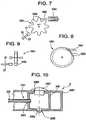
- Fig. 7illustrates a linear actuator for use with a fluid transfer system according to some embodiments of the present invention.
- Fig. 8illustrates a piezo-electric actuator for use with a fluid transfer system according to some embodiments of the present invention.
- Fig. 9illustrates a reusable sensor for a fluid transfer system according to some embodiments of the present invention.
- Fig. 10illustrates a partial cross sectional view of a depletable unit II according to some embodiments of the present invention.
- Fig. 11illustrates a partial cross-sectional view of a depletable unit II, having an injection unit III partially engaged therein according to some embodiments of the present invention.
- Fig. 12illustrates another partial cross-sectional view of the depletable unit II and injection unit III shown in Fig. 11 .
- Fig. 13illustrates a partial cross sectional view of a depletable unit II according to some embodiments of the present invention.
- Fig. 14illustrates a partial cross-sectional view of the depletable unit II shown in Fig. 13 , having an injection unit III partially engaged therein according to some embodiments of the present invention.
- Fig. 15illustrates a penetrating means of an injection unit III after retraction out of the depletable unit II of Fig. 13 , according to some embodiments of the present invention.
- Fig. 16illustrates a depletable unit II having a vent tube, and an injection unit III according to some embodiments of the present invention.
- Fig. 17illustrates a depletable unit II and an injection unit III according to some embodiments of the present invention.
- Fig. 18illustrates a partial cross sectional plan view of a depletable unit II according to some embodiments of the present invention.
- Fig. 19illustrates a partial cross sectional plan view of a depletable unit II according to some embodiments of the present invention.
- Fig. 20illustrates a block diagram of a fluid delivery system according to some embodiments of the present invention.
- Fig. 21is a schematic diagram of a pressure sensor device according to some embodiments of the present invention.
- Fig. 22is a schematic diagram of the integration of delivery and receiving contacts into structure of a pressure sensing device according to some embodiments of the present invention.
- Fig. 23is a graph of a pulse train derived by piezo-electric pressure sensor according to some embodiments of the present invention.
- Fig. 24is a block diagram of an electronic circuit for a reusable unit according to some embodiments of the present invention.
- Fig. 25is a schematic diagram of a reusable unit I and a depletable unit II, separated, according to some embodiments of the present invention.
- Fig. 26is a schematic diagram of the reusable unit I and the depletable unit II, connected, according to some embodiments of the present invention.
- Fig. 27is a side view of an assembled reusable unit I and depletable unit II, positioned next to the skin of a patient, according to some embodiments of the present invention.
- Fig. 28is a schematic diagram of a reusable unit I and depletable unit II, separated, with injection unit III depicted symbolically (coupled to unit II in the plane of the figure), according to some embodiments of the present invention.
- Fig. 29is a schematic diagram of the reusable unit I and the depletable unit II shown in Fig. 28 , connected.
- Fig. 30is a block schematic diagram of a remote control unit IV according to some embodiments of the present invention.
- Fig. 1is a block diagram of an exemplary system 1000 for implementing a sustained controlled injection (preferably at a predetermined rate) of a liquid into the skin or subcutaneously into the body of a patient.
- body Bis regarded as meaning: subcutaneously into the body B, and may also refer to intravenous ejection.
- the system 1000includes a reusable unit I, a depletable unit II, an injection unit III, and a remote control unit IV (unit IV), which are separate units.
- Unit I and unit IVare each reusable, while the depletable unit II and the injection unit III are both preferably disposable and together may form a disposable portion or unit that is discarded after one single use.
- Units I, II and IIItogether form a fluid dispensing device.
- a user Uselects a reusable unit I and a depletable unit II, and programs the system 1000, preferably by use of the remote control unit IV.
- the depletable unit IImay then be filled with a desired liquid and upon purging of air be coupled to the reusable unit 1.
- An injection unitis selected and introduced into the depletable unit II.
- units I, II and mare applied onto and preferably adhered to the skin S, while a needle pierces through the skin S, and into the body B.
- Units I and IImay be flexible envelopes, possibly transparent with at least unit II being releasably adherable to the skin S.
- the remote control unit IVmay then be operated to program the fluid dispensing device to command flow of the liquid from the depletable unit II and into and preferably through the skin S (i.e., subcutaneously) into the body B.
- the user Uis either an operator applying the system 1000 on a body, or a patient helping himself.
- unit Imay include one or more (and preferably all), generally, of the following components: a control, command and transceiver module 101 (or controller and transceiver 101), for control and communication in the management of fluid injection, and for bi-directional communication with the remote control unit IV.
- a controlcommand and transceiver module 101 (or controller and transceiver 101), for control and communication in the management of fluid injection, and for bi-directional communication with the remote control unit IV.
- unit Imay be an engine 103 for imparting motion to a fluid transfer element 105 of a fluid transfer system, or transfer element 105 for short.
- the fluid transfer systempreferably comprises components belonging to both unit I and unit II.
- the fluid transfer systemmay comprise the engine 103, the fluid transfer element 105, a flexible tube 205 and a backing plate 207, the latter two elements being preferably included in unit II.
- unit Ipreferably is first coupled to the depletable unit II, to obtain power therefrom, and because the transfer element 105 operates in conjunction with the tube 205 and backing plate 207 contained in unit II.
- the transfer elementmay have a first, main portion disposed in the first unit I, and a secondary portion disposed in the second unit II.
- first unit I and the second unit IIare coupled in operative association, transfer of fluid out of the second unit II may occur, on condition that power is supplied to the engine 103.
- the depletable unit IIpreferably includes, in general, one or more batteries 201 for powering the reusable unit I, a reservoir 203, which either comes pre-filled with the liquid for dispensing or is filled with the liquid prior to use, and a tube 205 coupled to the reservoir for delivery of the liquid to a well 206.
- the liquidwhich is not shown in the figures is injectable only after the injection unit III is coupled to provide fluid communication with the depletable unit II and the infection unit III is inserted into skin S or body B.
- the injection unit IIIincludes mainly a needle 301, which is assembled to a trocar.
- the injection unit IIIis inserted into the depletable unit II, at well 206.
- Well 206is coupled in fluid communication with the tube 205.
- the needle 301is inserted through the well 206 and into the body B through the skin S.
- the penetrating means 303may be retrieved and fluid is injected, as dosed and dispensed at a predetermined rate by the fluid transfer system.
- the liquidmay be a beneficial fluid or a therapeutic agent.
- each one of the three units I, II, and IIImay be various types of each one of the three units I, II, and III, where each one type of the same unit (i.e. I, II, or III), being interchangeable and replaceable with the other type.
- the different types of units I, II, and IIImay all be configured to be releasable coupled for operation.
- diverse types of reusable units Imay include a controller and transceiver module 101 with a chosen level of sophistication and optionally, an I/O pad and/or connection, a safety sensor, and may include further options.
- different types of depletable units IImay have a reservoir 203 of different size, batteries of diverse capacity, and contain an alternative liquid.
- the injection unit IIImay have a needle that is shorter, longer, be suitable for insertion at an angle or perpendicularly to the skin, or be of a different kind, according to needs.
- the various components of the reusable units I and of the depletable units IIare preferably all disposed as a single layer, arranged and supported on the same plane, and preferably so are their corresponding connections and couplings.
- the two units I and IIWhen assembled and adhered to the skin S, side-by-side along their thickness dimension (i.e., in end-to-end disposition), the two units I and II preferably cover an area not larger than about half the size of a plastic credit card (or smaller), or typically a region measuring about 65mm by about 25 mm.
- Unit IIIpreferably does not add to the covered area.
- Both the reusable unit I and the depletable unit IIare preferably hermetically sealed and each may form a flexible envelope that remains sealed even while in use.
- one face or surface of the envelope of unit I and of unit IImay be configured for application in mutual assembly to the skin S, as a skin conforming patch, at most some 4 mm high (for example).
- the reusable unit Imay be releasably latched to unit II, and at least unit II (but also unit I if desired), may releasably adhere to the skin S.
- the needle 301may differ in length according to type.
- needle 301may be sized to penetrate subcutaneously for only 3 mm, or as deep as 30 mm. After removal of the penetrating means 303, the height of the skin-attached units preferably does not increase.
- the fluid transfer systemis a peristaltic positive displacement pump - where the fluid transfer tube 205 is squeezed to transfer fluid from the reservoir for injection to the body of the patient.
- the first (main) portion of the peristaltic positive displacement pump, as well as the engine 103 to drive that pump,may be included in unit I.
- the tube 205, the backing 207, the liquid in the reservoir 203, and batteries 201 for driving unit Imay be included in the depletable unit II.
- actual injection of the liquidis possible only when at least the units I and II are coupled together for operation.
- Fig. 2is a schematic illustration showing an edge portion of unit I when attached to unit II, illustrating an exemplary fluid transfer system according to some embodiments of the invention.
- a single toothed wheel, or cogwheel 1051, or gear 1051, with teeth 1053is appropriately disposed to compress the exterior wall of the flexible tube 205, which is seen be coupled to and exiting out of the reservoir 203.
- the tube 205is compressed between the teeth 1053 of the gear 1051 and backing 207 disposed adjacent and tangentially to the gear 1051.
- the backingmay comprise a flat or curved back plate 207.
- the backing 207is loaded by a spring 2070 biased against a static base 2074.
- a quantum of fluid 1055trapped between two adjacent teeth 1053 of the gear 1051, is transferred along the tube. Transfer of liquid occurs from an upstream suction side 31, adjacent the reservoir 203, to a discharge side 33 downstream of the transfer element 105, leading the liquid to well 206, and eventually to the needle in unit III.
- the flexile tube 205extends between the reservoir 203 and the well 206.
- engine 103may be operated continuously, or at appropriately selected time intervals, according to the rate of fluid to be dispensed.
- the fluid transfer systemincluding the gear 1051, backing 207, and teeth 1053, substantially guarantees and preferably permanently prevents a direct flow, in either or both directions, to the suction side 31 or the discharge side 33, thereby enhancing safety of use. Accordingly, such fluid transfer systems, according to some embodiments of the present invention, allow control of the direction of flow of the fluid without requiring valves; as long as at least one tooth 1053 completely compresses the tube 205 and blocks the passage of liquid, no valves are required. Use of the foregoing positive displacement pump is not associated with backpressure , and thus, backpressure drop will not occur.
- the dispenserdelivers the infused fluid in discrete, equal-sized volumes of between about 0.2 - 1 of 10 -4 cc per roller or tooth 1053.
- Flow ratemay therefore be provided in minute quanta and can be precisely controlled simply by regulating the speed of rotation of the wheel 1051. In other words, flow rate can be measured simply by counting rollers, or teeth, as they rotate past the tube 205.
- at least one roller, or tooth 1053preferably always depresses tube 205, which substantially eliminates (and preferably eliminates) a hydraulic "short circuit" (i.e., direct communication between the reservoir and the well 206).
- "n"ranges from 0 to a maximum
- v tis defined according to the selected configuration of the cogwheel 1051.
- High accuracy of the quantity of transferred liquidmay thus be achieved by programming the controller and transceiver 101, to appropriately control the parameter n for a given v t .
- the reservoir 203is preferably configured either as a flexible container, or as a resilient collapsible and expandable bladder (or other collapsible fluid retention device).
- the reservoir 203may include a self-sealing filling port 2031, permitting a user U to fill the reservoir using a syringe (not shown in the drawings). To that end, the user U selects a desired liquid, and fills the syringe. Then, the needle of the syringe is used to pierce the self-sealing filling port 2031 of the reservoir 203, and the selected liquid is injected into the container 203, or bladder 203, which expands during filling up to a maximal volume.
- the user Umay manually purge air out of the unit II prior to using the device. After fining the reservoir 203, the syringe is evacuated from the filling port 2031, which self-seals the reservoir.
- the reservoir 203is preferably manufactured integrally with the tube 205, or hermetically attached thereto by virtue of a conventional connector (not shown in the figures).
- the reservoir 203may be provided readily pre-filled from factory.
- the expansion of the bladder-type reservoir 203may be limited, say by a cage ar by an enclosure not shown in the figures, or left free to expand until arrested by a component of unit II or a housing thereof. In some embodiments, when left free, the bladder-type reservoir 203 may expand in all directions and penetrate into available interstices, even filling gaps remaining open between components, taking maximum advantage of unused space.
- the separation line SLindicates the abutting edges of unit I and unit II, clearly illustrating that fluid transfer will not occur when units I and II are separated, because the wheel 1051 will be distanced away from the tube 205, and the engine 103 will be deprived of power received from the batteries 201.
- Each unitmay comprise a specific type for a specific application/treaiment.
- each typemay be distinguished from another by, for example, fluid contents, a reservoir 203 of chosen size, and/or batteries of given power.
- Fig. 3illustrates another embodiment of the wheel 1051, with freewheeling rollers 1057 supported at the extremities of all the teeth 1053, to provide for low rolling friction.
- Fig. 4depicts a partial cross-section of a further embodiment, where the rollers 1057 are supported freely and rotatably between two plates 1059.
- the outer circumference of the plates 1059may exceed that of the rollers 1057, so that the diameter of the tube 205 is partially or completely disposed between the two plates 1059.
- the plates 1059may be geared for engagement with other geared driving means. If desired, only one plate 1059 with rollers 1057 is sufficient. Other embodiments of support plate are possible.
- Fig. 5illustrates an example of a transmission of rotational motion from the motor 103, via reduction gears, to a gear 1051 or to a geared plate 1059.
- the engine 103here motor 103, drives a first spur gear 1061 that engages a second spur gear 1063 of diameter larger than that of gear 1061.
- a third spur gear 1065concentrically fixed to and of diameter smaller than that of the second spur gear 1063.
- engages a fourth spur gear 1067of diameter larger than that of the third spur gear 1065, to which a worm gear 1069 is affixed concentrically.
- the worm gear 1069rotates the gear 1051.
- Fig. 6is another example of a gear train reduction mechanism.
- the motor 103drives a worm gear 1071, which engages a spur gear 1073 having a concentrically mounted smaller diameter spur gear 1075 affixed thereto. That last spur gear 1075 rotates the gear 1051 or the plate 1059.
- Other transmission configurationsare possible, by friction, gears, and flexible shafts, for example.
- Fig. 7presents a linear actuator 1081, such as a solenoid, with a reciprocating plunger 1083 sinking a tooth 1053 to drive the wheel 1051 counterclockwise.
- a linear actuator 1081such as a solenoid
- Fig. 8shows a piezoelectric actuator 1091 tangentially engaging a tooth 1053 on the periphery of a wheel 1051 or plate 1059 for providing counterclockwise rotation.
- a pulse of powercauses the piezoelectric actuator 1091 to deliver one tangential strike to a tooth 1053, and to rotate the wheel 1051.
- transmission and reduction mechanismsmay also be possible, which may utilize planetary, rolling, and friction gears, rack and teeth mechanisms, and belts, whether alone or in combination.
- a simple reusable sensormay be optionally mounted on unit 1.
- Fig. 7shows schematically a reusable sensor 21 which may be used in embodiments of the present invention and which is disposed opposite a tooth 1053, in the plane of the wheel 1051.
- One or more leads 23connect between the sensor 21 and the controller and transceiver 101.
- the reusable sensor 21is selected as an appropriate component of a type known in the art, such as capacitive, inductive, magnetic, mechanic, or optic sensor, or a combination thereof.
- the reusable sensor 21is disposed opposite a tooth 1053, as shown in Fig. 9 .
- the controller and transceiver 101may compare the commanded rotation rate of the wheel 1051 with the output of the reusable sensor 21, and emit correction signals to the transfer element 105 (if necessary).
- an arrow coupling from the transfer element 105 to the controller and transceiver 101indicates feedback, for use in some embodiments, allowing the controller to respond accordingly when necessary. The reliability of the system 1000 is thereby enhanced.
- the batteries 201 in unit IIare electrically connected to delivery contacts 2209, which may be appropriately disposed to couple with the receiving contacts 107 disposed in unit I.
- the receiving contacts 107may be connected to the controller and transceiver 101, and to the engine 103, which actuates the fluid transfer element 105.
- unit IIis discarded and replaced, while unit I may be reusable.
- Fig. 10is a partial cross-section of a portion of the depletable unit II according to some embodiments, showing the envelope 2001, the downstream extremity 2051 of the flexible tube 205, which is coupled in fluid communication to the well 206.
- the well 206When the well 206 is filled with the liquid it may be supplied for injection via the injection unit III.
- the well 206functions as a receptacle for the liquid and it is provided with a tube inlet 2061 to which the downstream extremity 2051 of the tube 205 is attached, with an entry aperture 2063, and with an exit aperture 2065.
- the entry aperture 2063 and the exit aperture 2065are preferably releasably and hermetically sealed by, respectively, an entry plug 2067 and an exit plug 2069.
- a peel-off label, or other sealing means,may be provided instead of the entry plug 2067 and the exit plug 2069.
- the well 206may extend from the entry aperture 2063 to the exit aperture 2065, being substantially directed across the whole height of unit II, and may also be perpendicular to the tube 205.
- the exit aperture 2065may be flush with the proximal surface of unit II to be adhered to the skin S, and the entry port 2063 may open on the opposite surface of unit II, which is the distal surface, pointing away from the skin. This disposition of the well 206 may be considered as a vertical disposition.
- the depletable unit IIWith liquid in the reservoir 203, and before using the system 1000, the depletable unit II is coupled to the reusable unit I. Then, as shown in Fig. 10 , the exit plug 2069 may be removed, whereby the exit opening 2065 is exposed and permits passage of liquid.
- commandis provided, say, by use of the remote control unit IV, to enable the dispenser device pump to urge liquid out of the reservoir 203 and into the well 206 via the flexile tube 205 extending between the reservoir and the well.
- liquidis released through the exit opening 2065, so that when unit II is held (appropriately), with the exit aperture 2065 turned upwards (for example), air will be purged out of the unit II.
- airmay be purged manually, prior to coupling, as described hereinabove.
- the entry plug 2067may be removed so that both the entry aperture 2063 and the exit aperture 2065 may be open to permit free introduction of the injection unit III into the well 206.
- Fig. 11shows an example of an injection unit III partially engaged into the depletable unit II.
- the sharp tip 3031terminates the penetrating extremity of the penetrating means 303, shrouded by a cannula 305. It is seen that the cannula, has already pierced through the skin S.
- the injection unit IIIis preferably translated toward and into the unit II, until it is fully engaged and seated therein, and then the penetrating means 303 is retrieved out and away from the injection unit III, and discarded.
- a handle 3033may be fixedly attached to the penetrating means 303.
- the handle 3033itself, as a separate part, is not essential in embodiments of the present invention since the grip extremity 3035 of the penetrating means 303 may be formed as a handle, for example, as a hook or as a ring.
- the penetrating means 303may have a solid cross-section as a dagger, or be hollow for air purging purposes (for example).
- the cannula 305is open at the skin-contacting extremity 3051 and is preferably firmly attached to a plug 3053 at the opposite extremity.
- the plug 3053may be configured with a rim 3055 to permit only a single one-way insertion via the entry opening 2063 of unit II.
- At least one radial bore 3057may be provided into the cannula 305 to permit fluid communication from the interior of the well 206 into the lumen of the cannula.
- Fig. 12depicts the cannula 305 when inserted into the body B and fully seated in unit II, with the penetrating means being already retrieved.
- the cannula 305may be anchored by the plug 3053 in the interior of a trap 2071 formed in unit II.
- the plug 3053may be captive between the extension 2073, at the rim 3055, and the step 2075.
- the plug 3053seals liquid flowing into the well 206 via the tube 205, to keep it from spilling out of the entry opening 2063.
- the spilling of fluid out of the exit opening 2065is prevented by the envelope 2001 acting as a seal, or by a dedicated exit seal 2076; or by both.
- the viscoelastic envelope 2001it is possible to use the viscoelastic envelope 2001 to seal the entry opening 2063.
- liquid contained inside the well 206is prevented from escaping via the entry opening 2063 and/or the exit opening 2065, but may flow into the cannula 305 via the radial bore 3057 and out of the cannula via discharge opening 3059. Accordingly, liquid transferred out of the reservoir 203 is provided for injection into the skin S or the body B of the patient.
- Fig. 13is another embodiment of a well, showing a well 206 with an entry aperture 2063 and an exit aperture 2065.
- the well entry aperture 2063is disposed adjacent the distal surface opposite an entry port 2003 provided in the envelope 2001.
- the entry port 2003is blocked by an entry seal 2085, which may be either simply a portion of the envelope 2001, or be a viscoelastic seal embedded in the envelope as an insert.
- the entry seal 2085may be manufactured by double-injection or by a similar production technique.
- the well exit aperture 2065is preferably disposed adjacent the proximal surface, opposite the entry port 2003 provided in the envelope 2001. It is through the exit aperture 2065 that air may be purged.
- Fig. 14illustrates another embodiment of an injection unit III that has been inserted into the well 206 shown in Fig. 13 .
- the injection unit IIImay include a ram 3038 disposed intermediate the handle 3033 and the cannula 305, which is fitted with the penetrating means 303.
- One side of the ram 3038may be fixedly attached to the handle 3033, and the opposite side of the ram, may be fixedly attached to the penetrating means 303.
- the ram 3038drives the cannula 305 until the handle 3033 is arrested by abutment on unit II. In that arrested position, which is depicted in Fig. 14 , the cannula 305 is retained in place by friction at the well 206 and at unit II.
- Fig. 15shows the penetrating means 303 after retraction out of the depletable unit II, and ready to be discarded.
- the cannula 305is retained in the body B enabling liquid to flow out of the tube 205, into the well 206, and from there, into the cannula inlet opening 3063, via the cannula discharge opening 3059, and into the body.
- the entry aperture 2063 and the exit aperture 2065may be appropriately sealed to assure flow of liquid only via the cannula 305, and thus prevent unwanted escape and loss of liquid out of the well 206.
- Fig. 16shows a well 206 featuring a vent tube 2091 with a vent tube inlet 2093, and a vent tube outlet 2095, providing for fluid communication from the interior of the well 206 to the exterior of the envelope 2001.
- the vent tube 2091may be inserted into the well 206 and the envelope 2001; the well and envelope may be made of viscoelastic material to seal fluid exit but via the lumen of the vent tube 2091.
- a capmay be included for covering the vent tube outlet 2095, but it is not shown in the figures, since it is removed prior to use. If desired, an entry seal 2085 may be appropriately disposed in the envelope 2001. As described hereinabove, air may be purged before or after coupling of the reusable unit I with the depletable unit II.
- an embodiment of the injection unit IIIis the same as that of Figs. 14 and 15 .
- the penetrating means 303 and the cannula 305pierce both the envelope 2001 and the well 206, and also pierce the entry seal 2085, if it is mounted.
- the bottom portion 3037 of the handle 3033pushes the vent tube 2091 into the well 206 and seals the vent tube outlet 2095.
- the cannula 305is retained in position due to friction, as described hereinabove with reference to Figs. 14 and 15 .
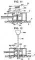
- Fig. 17shows a cannula 305 driven by a cannula driver 3039 that is fixedly retained to the handle 3033 of the penetrating means 303.
- the cannula driver 3039is affixed to the handle 3033 and to the penetrating means 303 instead of the ram 3038 shown in Figs. 14, 15 , and 16 .
- the cannula driver 3039operates in association with a cannula 305 having a male screw thread 3058 disposed on the exterior portion adjacent the cannula inlet opening 3063.
- the cannula driver 3039may be configured to engage the cannula inlet opening 3063 or a portion of the cannula adjacent thereto, to allow longitudinal insertion into the well 206, and rotation of the cannula.
- the penetrating means 303is preferably linearly driven into the well 206 and then rotated to engage the screw thread 3058, either in self-tapping mode, or to engage a matching female screw thread appropriately provided, in the exit opening 2065.
- the penetrating means handle 3033may be pulled out of the unit II, which may also retrieve the cannula driver 3039.
- the cannula inlet 3063is now open to permit transfer of liquid from the well 206 to the skin S or body B.
- the cannula 305is shown for insertion in perpendicular direction into the skin S.
- other configurationsmay be possible which permit insertion of the cannula 305 at other desired angles.
- Fig. 18depicts still further embodiment of the dispenser, which is provided with a rotary joint 60 allowing rotation of the injection unit III in both clockwise and anticlockwise direction, for insertion of the cannula 305 at any angle from 0° to n360°, with n ranging from 0 to ⁇ .
- insertionmay be made at an angle ranging between the vertical and horizontal direction of the cannula relative to the skin S.
- Fig. 18is a partial cross-section of a plan view of unit II, showing the downstream extremity 2051 of the flexible tube 205 fixedly coupled in fluid communication with the entry aperture 2063 of the well 206.
- the well 206is disposed in a horizontal position, being substantially parallel with the skincontacting surface of unit II.
- the entry aperture 2063preferably opens into a trap 2071 forming a cavity for liquid accumulation.
- the cavityis restricted by a step 2075 to form a cylindrical exit aperture 2065 of the well 206 that emerges onto a side wall or height surface of unit II.
- the entry aperture 2063is concealed and contained in the interior of unit II.
- the rotary jointmay be provided with a rotary fastener 61 coupled with the exit aperture 2065 of the well 206
- An exterior portion 62 of the rotary fastener 61supports an entry seal 2085 and a cannula 305, which is provided with a radial bore 69.
- the cannulais directed perpendicularly with respect to the well 206.
- the rotary fasteneris provided with an internal channel, which provides fluid communication with the well and with the radial bore 69 of the cannula.
- the rotary fastener 61includes an interior portion 63 terminating by resilient expandable jaws 65, and a cylindrical stem 66 intermediate the exterior portion 62 and the jaws 65.
- the interior portion 63 of the rotary fastener 61is preferably retained within the cylindrical exit aperture 2065.
- the resilient jaws 65may be prevented from exiting out of the trap 2071 by virtue of the step 2075 and then stem 66 may be rotated in the cylindrical exit aperture 2065.
- An O-ring seal 64 intermediate the cylindrical exit aperture 2065 and the stem 66prevents leakage of fluid.
- the rotary fastener 61may thus be free to rotate relative to the well 206 and the unit II.
- a tongue 67may be fixedly attached to the unit II for accommodating within grooves 68 cut on the periphery of the exterior portion 62 of the rotary fastener 61.
- the cannula 305Before introduction of a "dagger" penetrating means 303 fitted with a handle 3033, and upon filling the reservoir 203 and purging out of air, the cannula 305 may serve for the exit of liquid. However, it is also possible to purge air when the cannula 305 is fitted with the penetrating means 303.
- the penetrating means 303is hollow, and is provided with a radial bore 69 for liquid communication with the well 206 and with the exterior of unit II.
- Fig. 18the cannula 305 is received within the fastener 61 and is situated inside a cutout 71 provided in the unit II.
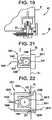
- Fig. 19A different embodiment of the rotary joint is shown in Fig. 19 , in which the unit II not provided with the cutout 71.
- the tongue 67 and the grooves 68may be disposed slightly differently.
- unit IIImay include a dagger penetrating means 303 fitted with a handle 3033, or including a hollow penetrating means 303 with a handle 3033.
- Unit IIImay take advantage of any of the embodiments depicted in the Figs 11 to 17 .
- the unit IIIincludes rotary fastener 61 with the penetrating means 303 and the cannula 305 already inserted therein.
- the well 206may be fitted with an exit plug 2069, which may be removed for air purging.
- Fig. 20shows optional components for integration with the reusable unit I, as embodiment 2000.
- Such optionsmay include an Input/Output pad (or I/O pad) 102, a safety device 104, an alarm 106, and one or more rechargeable batteries 108.
- the I/O pad 102may be fitted with input means such as button(s) and/or keys, or a USB port, and output means such as LEDs, and even with a display if desired.
- the I/O pad 102is coupled to, and receives input and output commands from both, the controller and transceiver 101, and from the user U.
- a safety device 104may be coupled to an independent flow sensor configured to monitor the fluid pressure pulses delivered to the downstream extremity 2051 of the flexible tube 205.
- the safety device 104may directly sense pulses of liquid pressure generated in the tube 205.
- the addition of a stand-alone fluid flow sensor, not shown in the figures,may be added if desired, to enhance the reliability of the system 1000.
- Fig. 21is a schematic presentation of an exemplary pressure sensor device.
- the tube 205is seen in cross-section, supported by a rigid base 2011 carried by the depletable unit II, while a rigid bridge 1041 disposed on the reusable unit I, embraces the tube 205.
- the bridge 1041may include one or more legs, and preferably, two legs 1043, distanced and separated apart, both legs may be supported on the base 2011, and one beam 1045 supported by the two legs 1043.
- the separation line SL in Fig. 21indicates a border between unit I and unit II, and thus marks the separation line between the bridge 1041 and the base 2011. When both units I and II are coupled together for operation, the tube 205 is tightly encaged in a rigid frame formed by the bridge 1041 and the base 2011.
- a piezoelectric pressure sensor 1047may be retained in the beam 1045 disposed opposite the base 2011 to be in direct mechanical contact with the tube 205.
- the piezoelectric pressure sensor 1047senses that pulse, which is translated into an electrical signal communicate via a couple of leads 1049 to the controller and transceiver 101.
- Fig. 22shows schematically an advantage taken from the disposition of the two legs 1043 to integrate both the delivery and receiving contacts, respectively 2209 and 107, into the structure of the pressure sensor device 1047.
- a receiving contact 107may be disposed in the free extremity 1044 of each leg 1043, and a delivery contact 2209 may be disposed opposite thereto on the base 2011.
- a lead 1048may be electrically coupled to each receiving contact 107 passing in the interior of each leg 1043.
- a lead 2013may be electrically coupled to each delivery contact 2209 passing through the base 2Q 11.
- each one or both contacts out of a pair comprising a delivery contact 2209 and a receiving contact 107may be springloaded for better conductance, if desired.
- the piezoelectric pressure sensor 1047which responds by emitting signals in proportion to trains of quanta of fluid 1055 flowing through the tube 205, may easily detect basal and bolus fluid flow patterns, and report accordingly to the controller and transceiver 101. Furthermore, high pressure, such as caused by an occlusion, or low pressure, such as caused by a leak, i.e. disengagement or rupture, will also easily be detected and reported.
- each pulsemay be characterized by an amplitude A, by a pulse width w, and by a distance T separating two consecutive pulses, indicative of the period T.
- Fig. 23shows a graph as an example of a pulse train derived by the piezoelectric pressure sensor 1047, with respect to a set of coordinates having an abscissa t, indicating time, and an ordinate y designating amplitude.
- the pressure pulse waveformcontains information regarding the operational status of the system 1000, say as represented by the three parameters A, w, and T.
- the amplitude Amay be proportional to the pressure of the liquid in the tube 205, and preferably remains within predetermined boundaries. Too high an amplitude A, thus too high a pressure, may indicate an occlusion. On the contrary, low pressure may point to a leak, such as a rupture, release, disconnection, or even lack of liquid.
- the period Tmay be proportional to the speed of rotation of the wheel 1031 of the transfer element 105, thus proportional to the volume of injected quanta of liquid.
- the coefficient kis an empirical one-dimensional coefficient, and depends on the interior diameter of the tube 205.
- the safety device 104is a valuable independent support tool enhancing the reliability of the system 1000 regarding the delivery of alarm in case a trend pointing to a developing dangerous situation or to an imminent danger is detected in some embodiments of the invention.
- one or more safety devices 104may be added, such as a flow sensor, in replacement of, or in addition to the pressure sensor 1047.
- An alarm module 106may be provides, which may be coupled to the receiving contacts 107 providing power, and to the controller and transceiver 101.
- the alarm module 106may be used to provide alert in response to a danger signal emitted by the controller and transceiver 101, and/or by the safety device 104.
- the alarm module 106may be implemented to emit an audible, visual, or sensory signal, by operation of, respectively, a buzzer, a light, or a vibrator.
- the vibratoris the preferred implementation since unit I is disposed on the skin S, also preferred because the delivered signal is a privately sensed one, without the surroundings being aware thereof.
- An alarmmay be given in response to a signal from the controller and transceiver 101, according to at least one of the following: a detected unacceptable condition and performance of the engine 103, a signal from the reusable sensor 21, or a signal from the safety device 104.
- the safety device 104may be coupled to the alarm module 106 via the controller and transceiver 101, or directly thereto, even though such a connection is not shown in the figures.
- the engine 103, the safety device 104, and the transfer element 105are activated only after operative connection of the reusable unit I with the depletable unit II is established.
- the controller and transceiver 101may emit wireless alarm signals to the remote control unit IV, which may relay those alarm signals to other external receiving devices, computers, and networks.
- a batterypossibly a rechargeable battery 108, is also integrated within the reusable unit I, to provide additional reliability to the system 1000.
- the battery 108may be charged by connection to an external battery charger via a charging port.
- controller and transceiver 101are shown coupled to the I/O pad 102, the engine 103, the safety device 104, the transfer element 105, the alarm 106, and in bi-directional wireless communication with the remote control unit IV.
- the controller and transceiver 101may be microprocessor-driven for commanding and managing units I and II, and configured to support bi-directional wire and wireless communication with the remote control unit IV.
- Fig. 24illustrates an exemplary block diagram presenting the electronic circuit of the controller and transceiver 101, which is a control-with-transceiver module.
- a microprocessor (or ⁇ P) 1011having one or more memories 1012, is coupled to a transceiver 1013 having an antenna 1014.
- the ⁇ P 1011may also be coupled to an engine driver 1015, an A/D converter 1016, which in turn, is coupled to a MUX 1017.
- the ⁇ P 1011may be configured to read, operate and run computer programs stored in the one or more memories 1012, referred to hereinbelow as the memory 1012, as well as to respond to instructions and commands.
- the ⁇ P 1011receives commands from the remote control unit IV via the antenna 1014 and the transceiver 1013, then fetches data and computer programs from the memory 1012, and stores data therein.
- the transceiver 1013also preferably communicates with the memory 1012 to store programs and data therein and to retrieve data therefrom. It is via the antenna 1014 that the transceiver 1013 communicates with the remote control IV, and if desired, with other receivers, emitters or transceivers, not shown in the figures.
- the ⁇ P 1011may then emit commands to the engine driver 1015 for activation of the engine 103, and receives feedback from one or more safety device(s) 104. From the received feedback, the ⁇ P 1011 may derive comparisons, and may, if necessary, emit correction commands to the engine driver 1015.
- Feedback signals from the safety device(s) 104, received from analog sensors,may be fed to the ⁇ P 1011 via a MUX 1017, and converted by an A/D convener 1016 into digital signals.
- data and commandsmay be exchanged between the ⁇ P 1011 and the I/O pad 102.
- the ⁇ P 1011may also activate the alarm 106 when necessary.
- Power for running the ⁇ P 1011may be obtained from the receiving contacts 107 coupled to batteries mounted in unit II, or to an optional battery 108, rechargeable or not, mounted on unit I.
- the electronic circuit of the controller and transceiver 101may be integrated in a manner well known to the art, as a low power-consuming single chip, such as an ASIC, i.e. Chipcon®, Zarlink®, and the like.
- Fig. 25shows unit I and unit II separated from each other, while unit III is depicted symbolically as being coupled to unit II, even though shown in the plane of the paper instead of being in perpendicular thereto.
- Unit IImay include releasable latching arms 21 and a recess 23 to receive unit L
- Unit Imay include latching grooves 22 configured to engage the latching arms 21, to firmly but releasably retain both units I and II together.
- both the wheel 1051 and the sensor 1047when both units I and II are latched together, both the wheel 1051 and the sensor 1047 appropriately abut the tube 205, and likewise, the delivery contacts 2209 engage the receiving contacts 107.
- Fig. 27is a side elevation of the latched units I and II.
- a strip of peel-off tape 24covers a layer of adhesive 25. With the tape 24 taken off, the unit II may be brought in contact with the skin S, not shown in Fig. 27 , to adhere thereto. If desired, but not shown in Fig. 27 , adhesive may be added to unit I in the same fashion as described for unit II.
- Fig. 28presents another embodiment, which also shows unit I and unit II separated from each other, while unit III is again depicted symbolically as being coupled to unit II in the plane of the paper instead of being in perpendicular thereto.
- Unit IIis shown to have a cradle 28 for releasably receiving unit I therein.
- Fig. 29depicts unit I securely snapped into the cradle 28, but releasable therefrom when depleted.
- the bottom of unitI may also be covered with peel-off tape 24 covering a layer of adhesive.
- An O-ring 29. or other sealing element 29,may be coupled to unit I to ensure sealing when engaged with unit II.
- Fig. 30is a block diagram of an example of the remote control unit IV, which is a handheld set operated by the user U.
- the remote control unit IVis the user interface with the system 1000, by which programs and/or commands are emitted and received, and the system 1000 is operated and controlled.
- microprocessor-driven command and control unit 401able to run computer programs stored in a memory 403, is coupled to a transceiver 405, which in turn is coupled to an antenna 407, for wireless bi-directional communication with at least unit I. Communication with external devices, computers, and networks is also possible, if desired.
- the command and control unit 401may also be coupled to a display 409, and to an alphanumeric keyboard 411.
- An alarm device 415such as a LED, a buzzer, or other known devices, may further be coupled to the command and control unit 401.
- Exchange of information, such as computer programs, memory data, instructions, and commandsis achieved with the system 1000 (for example), and with other external and remote devices, computers, and networks, not only via the transceiver 405, but also via an Infra Red port (or IR port) 421, and a USB port 423.
- system 1000for example
- other external and remote devices, computers, and networksnot only via the transceiver 405, but also via an Infra Red port (or IR port) 421, and a USB port 423.
- Power for operation of the remote control unit IVmay be supplied by a battery 425, which is replaceable, or reloaded via a battery charge port 427.
- the batterymay power the command and control unit 401, the transceiver 405, the display 409, and the alarm device 415. It is noted that the battery 425, the memory 403, the USB port 423, and the alarm 415, shown as single devices in Fig. 30 , may be implemented as multiple devices if desired.
- the memory 403 of the remote control unit IVmay be loaded with programs via the transceiver 405, or via the IR port 421, or via the USB port 423.
- the user Umay enter instructions and commands via the keyboard 411, to communicate via the transceiver 405 and the antenna 407, with the controller and transceiver 101 of the reusable unit I.
- Information received from sources external to the units of the system 1000, as well as data received from unit I,may be displayed on the display 409.
- the command and control unit 401may analyze system status and receive data for output of selected information and necessary alarms on, respectively, the display 409 and the alarm 415.
- the display 409may also be able to show various status data, such as liquid delivery rate, computer program actually running, and battery state.
- the exchanges of data and the communication processesmay be governed by known techniques ensuring data security and data integrity, and taking advantage of known handshaking and secured communication protocols, all well known to the art.
- a handset I/O padcan be disposed on the remote control unit IV, having the display 409, the keyboard 411, and the alarm 415.
- the user Uselects a liquid to be injected, such as insulin for example, and further chooses a desired type of unit II. If the reservoir 203 in mit II is not supplied pre-filled, the user U may manually fill the reservoir 203, taking care of purging air therefrom. Then, unit II with the reservoir 203 is operatively coupled to the reusable unit I. The user U now selects a type of unit III, as desired, or as needed. In turn, unit III is inserted into unit II to establish fluid communication therewith, whereafter the user U commands operation of the transfer element 105 to purge air out of the cannula 305. Next, unit III is operated for insertion of the cannula 305 into the skin S or subcutaneously into the body B, and the operationally assembled units I, II, and III are appropriately disposed for at least unit II to adhere to the skin.
- a liquid to be injectedsuch as insulin for example
- controller and transceiver 101may execute computer programs and instructions as commanded by the user U, via unit IV, or via the I/O pad 102. Computer programs and instructions may also be deliverable to the controller and transceiver 101 as captured from an external source. Emissions from external sources may be captured by unit IV through the wireless transceiver 405, via the antenna 407, or the IR port 421, or by wire via the USB port 423. Such external transmissions may be received from devices external to the system 1000, from remote computers or networks.
- liquidis dispensed from the reservoir 203 according to computer programs stored in memory, or in response to command from the user U.
- the engine 103activates the transfer element 105 in associative operation with the tube 205 and the backing 207, to fill the well 206.
- Unit IIIforwards liquid from the well 206 and into the skin S or subcutaneously into the body B.
- Faultless operation of the system 1000may be monitored by the controller and transceiver 101, and to enhance reliability, also supported by feedback signals received from a reusable sensor 21 disposed on the transfer element 105, and/or from the safety device 104 coupled to disposable sensors disposed on unit II.
- At least one rechargeable batterymay be disposed in unit I.
- the system 1000is thus an example of a sustained release delivery system for delivering a beneficial liquid at a predetermined rate to the skin S or body B.
Landscapes
- Health & Medical Sciences (AREA)
- Animal Behavior & Ethology (AREA)
- Veterinary Medicine (AREA)
- Anesthesiology (AREA)
- Biomedical Technology (AREA)
- Heart & Thoracic Surgery (AREA)
- Hematology (AREA)
- Engineering & Computer Science (AREA)
- General Health & Medical Sciences (AREA)
- Life Sciences & Earth Sciences (AREA)
- Public Health (AREA)
- Vascular Medicine (AREA)
- Dermatology (AREA)
- Infusion, Injection, And Reservoir Apparatuses (AREA)
- Reciprocating Pumps (AREA)
- External Artificial Organs (AREA)
Abstract
Description
- Embodiments of the present invention relate generally to a system for sustained medical infusion of fluids, and more particularly, to a system having a portable infusion device (preferably miniature) adherable directly to a patient's skin, for accurate dispensing of fluids from the device into the body of the patient Some embodiments of the present invention relate to the connection of two or more separate portions (e.g., planar connection), such as a disposable portion and a reusable portion, preferably forming a flexible, pliable and thin skin-compliant device (e.g., patch).
- Medical treatment of several illnesses requires continuous drug infusion into various body tissues, through subcutaneous and intra-venous injections (for example). Diabetes mellitus patients require the administration of varying amounts of insulin throughout the day to control blood glucose levels. In recent years, ambulatory portable insulin infusion pumps have emerged as a superior alternative to multiple daily injections of insulin. These pumps, which deliver insulin at a continuous basal rate as well as in bolus volumes, were developed to liberate patients from repeated self-administered injections, and allow them to maintain a near-normal daily routine. Both basal and bolus volumes must be delivered in precise doses, according to an individual prescription, since an overdose of insulin could be fatal. Therefore, insulin injection pumps must be highly reliable to prevent delivery of any unintentional excess insulin.
- Several ambulatory insulin infusion devices arc currently available on the market. Generally, these devices have two parts: a reusable portion, containing a dispenser, a controller and electronics, and a disposable portion containing a reservoir, a needle assembly, with cannula and penetrating means, and a fluid delivery tube. The insertion of a variety of needles of different length and insertion angles, as required by the location of the injection on the body, demands a great deal of skill and practice. Usually, the patient fills the reservoir, attaches the needle and the delivery tube to the exit port of the reservoir, and then inserts the reservoir into the pump housing. After purging air out of the reservoir, the tube and the needle, the patient inserts the needle assembly, penetrating means and cannula, at a selected location on the body, and withdraws the penetrating means. To avoid irritation and infection, the subcutaneous cannula must be replaced and discarded after two to three days, together with the empty reservoir.
- Examples of first generation disposable syringe-type reservoir and tubes were described in
1972, by Hobbs, in US Patent No. 3631847 , and in1973, by Kaminski, in US Patent No. 3771694 , and later byStempfle, in US Patent No. 4657486 , and bySkakoon, US Patent No. 4544369 . The driving mechanism of these devices is a screw thread driven plunger controlling the programmed movement of a syringe piston. Other dispensing mechanisms have been described including peristaltic positive displacements pumps, for example in1980, by Wilfried Schal et al, in US Patent No. 4197852 , and later bySchneider, in US Patent No. 4498843 , and byWolff, in US Patent No.4715786 . - These devices represent a significant improvement over multiple daily injections, but all suffer from several drawbacks. The main drawback is the large size and the weight of the device, caused by the spatial configuration and the relatively large driving mechanism of the syringe and the piston. The relatively bulky device had to be carried in a patient's pocket or attached to the belt. Consequently, the fluid delivery tube is long, usually longer than 40cm, to permit needle insertion in remote sites of the body. These incomfortable bulky devices with a long tube are rejected by the majority of diabetic insulin users, since these devices disturb regular activities, such as sleeping and swimming for example. Furthermore, the effect of the image projected on a teenagers' body is inacceptable.
- In addition, the delivery tube excludes some optional remote insertion sites, like the buttocks and the extremities. To avoid the tubing limitations, a second generation of such devices has been devised. These devices included a housing having a bottom surface adapted for contact with the patient's skin, a reservoir disposed within the housing, and an injection needle adopted for communication with the reservoir.
- This paradigm was described by
Schneider, in US Patent No. 4498843 ,Sage in US Patent No. 5957895 ,Connelly, in US Patent No, 6589229 and its European equivalentEP 1177 802 and byFlaherty in US Patents No. 6740059 and6749587 (US 2002/0169439 ), none of them being currently available on the market. US 200219169439 - The above-mentioned second-generation devices have several limitations. They are bulky, because the reusable dispensing portion including the driving mechanism, is assembled on top of the disposable needle/reservoir portion. Such a "sandwich shaped" design, and their stacking in at least two layers, leads to a relatively thick device having thiokness of between 15 to 20 mm. Moreover, upon the needle emerging from the bottom of the device during insertion (either manually or automatically), the needle is usually inserted perpendicular to the skin (e.g., a predetermined angle) that for most patients is inconvenient and requires some skill to accomplish. The device was abandoned by patients wanting to see the puncture site and preferring needle insertion angles of less than 30°.
- Second-generation devices with a positive displacement peristaltic dispenser, e.g.
Flaherty in US Patent No. 6749587 , are provided with the drive mechanism and engine contained within the reusable portion, which is positioned on top of the pumping wheel, contained within the disposable portion. This configuration exhibits major limitations that are associated with inefficient energy utilization, and constant, long term pressure of the pump's wheel(s) applied on a transfer tube during the entire shelf life of the dispenser. Due to long term pressure the operation of the dispenser might be associated with inaccuracies because of the creeping of plastic material, from which the transfer tube is made. Another disadvantage of the above-mentioned configuration is associated with the fact that it allows air purging only after assembling of all the parts of the dispenser and requires operating the engine. - Other drawbacks of second-generation devices include leaking connections between reusable and disposable portions, as well as unavailable water resistance. Finally, a major limitation for the widespread acceptance of first and second generation pumps is their extremely high purchase price, running from $4000 to $6000, and maintenance costs amounting to some $250 per year.
- Thus, there is a need for a mimiature portable programmable fluid dispenser having an insertion needle which does not required direct connection with a connecting tube, and that allows direct adhesion to the patient's skin at any desired location on the body, and that could be remotely controlled. Preferably, the disposable portion of the device should contain a reservoir allowing manual filling and purging of air. After connection of the reusable and the disposable portions, the thickness of the unified device should be small (e.g., less than five (5) mm). Furthermore, the reusable portion should contain a high precision peristaltic pump for very accitrate dispensing doses of fluid.
- In accordance with the present invention, there is provided a medical infusion system as defined in the appendant independent claim to which reference should now be made. Embodiments of the present invention are defined in the appendant dependent claims to which reference should now be made.
- Upon emission of appropriate instructions from the fourth unit, when all three of the first unit, the second unit, and the third unit are coupled together in associative operation and disposed on the skin of the patient and upon the cannula being inserted into the body of the patient, power is supplied to the engine for generating motion to the fluid transfer system, and liquid is transferred from the reservoir to the body, under control of the controller and transceiver.
- These and other embodiments, advantages and objects of the invention will become even more clear in view of the following detailed description and attached drawings, a brief description of which is set out below.
Fig. 1 illustrates a block diagram of a fluid delivery system according to some embodiments of the present invention.Fig. 2 is a schematic diagram of an edge portion of a first unit coupled to a second unit of a fluid dispensing device according to some embodiments of the present invention.Fig. 3 illustrates a first portion of a fluid transfer system according to some embodiments of the present invention.Fig. 4 illustrates a partial cross-section view of portions of a fluid transfer system according to some embodiments of the present invention.Fig. 5 illustrates a transmission system for transferring rotational motion in a fluid transfer system according to some embodiments of the present invention.Fig. 6 illustrates a transmission system for transferring rotational motion in a fluid transfer system according to some embodiments of the present invention.Fig. 7 illustrates a linear actuator for use with a fluid transfer system according to some embodiments of the present invention.Fig. 8 illustrates a piezo-electric actuator for use with a fluid transfer system according to some embodiments of the present invention.Fig. 9 illustrates a reusable sensor for a fluid transfer system according to some embodiments of the present invention.Fig. 10 illustrates a partial cross sectional view of a depletable unit II according to some embodiments of the present invention.Fig. 11 illustrates a partial cross-sectional view of a depletable unit II, having an injection unit III partially engaged therein according to some embodiments of the present invention.Fig. 12 illustrates another partial cross-sectional view of the depletable unit II and injection unit III shown inFig. 11 .Fig. 13 illustrates a partial cross sectional view of a depletable unit II according to some embodiments of the present invention.Fig. 14 illustrates a partial cross-sectional view of the depletable unit II shown inFig. 13 , having an injection unit III partially engaged therein according to some embodiments of the present invention.Fig. 15 illustrates a penetrating means of an injection unit III after retraction out of the depletable unit II ofFig. 13 , according to some embodiments of the present invention.Fig. 16 illustrates a depletable unit II having a vent tube, and an injection unit III according to some embodiments of the present invention.Fig. 17 illustrates a depletable unit II and an injection unit III according to some embodiments of the present invention.Fig. 18 illustrates a partial cross sectional plan view of a depletable unit II according to some embodiments of the present invention.Fig. 19 illustrates a partial cross sectional plan view of a depletable unit II according to some embodiments of the present invention.Fig. 20 illustrates a block diagram of a fluid delivery system according to some embodiments of the present invention.Fig. 21 is a schematic diagram of a pressure sensor device according to some embodiments of the present invention.Fig. 22 is a schematic diagram of the integration of delivery and receiving contacts into structure of a pressure sensing device according to some embodiments of the present invention.Fig. 23 is a graph of a pulse train derived by piezo-electric pressure sensor according to some embodiments of the present invention.Fig. 24 is a block diagram of an electronic circuit for a reusable unit according to some embodiments of the present invention.Fig. 25 is a schematic diagram of a reusable unit I and a depletable unit II, separated, according to some embodiments of the present invention.Fig. 26 is a schematic diagram of the reusable unit I and the depletable unit II, connected, according to some embodiments of the present invention.Fig. 27 is a side view of an assembled reusable unit I and depletable unit II, positioned next to the skin of a patient, according to some embodiments of the present invention.Fig. 28 is a schematic diagram of a reusable unit I and depletable unit II, separated, with injection unit III depicted symbolically (coupled to unit II in the plane of the figure), according to some embodiments of the present invention.Fig. 29 is a schematic diagram of the reusable unit I and the depletable unit II shown inFig. 28 , connected.Fig. 30 is a block schematic diagram of a remote control unit IV according to some embodiments of the present invention.Fig. 1 is a block diagram of anexemplary system 1000 for implementing a sustained controlled injection (preferably at a predetermined rate) of a liquid into the skin or subcutaneously into the body of a patient. The term "body B" is regarded as meaning: subcutaneously into the body B, and may also refer to intravenous ejection.- The
system 1000 includes a reusable unit I, a depletable unit II, an injection unit III, and a remote control unit IV (unit IV), which are separate units. Unit I and unit IV are each reusable, while the depletable unit II and the injection unit III are both preferably disposable and together may form a disposable portion or unit that is discarded after one single use. Units I, II and III together form a fluid dispensing device. - The following description of the operation of
system 1000 is merely for example only, and one of skill in the art will appreciate that other methods of operation are possible. Accordingly, a user U selects a reusable unit I and a depletable unit II, and programs thesystem 1000, preferably by use of the remote control unit IV. The depletable unit II may then be filled with a desired liquid and upon purging of air be coupled to the reusable unit 1. An injection unit is selected and introduced into the depletable unit II. After purging of air, units I, II and m are applied onto and preferably adhered to the skin S, while a needle pierces through the skin S, and into the body B. Units I and II may be flexible envelopes, possibly transparent with at least unit II being releasably adherable to the skin S. - The remote control unit IV may then be operated to program the fluid dispensing device to command flow of the liquid from the depletable unit II and into and preferably through the skin S (i.e., subcutaneously) into the body B. The user U is either an operator applying the
system 1000 on a body, or a patient helping himself. - As shown in
Fig. 1 , unit I may include one or more (and preferably all), generally, of the following components: a control, command and transceiver module 101 (or controller and transceiver 101), for control and communication in the management of fluid injection, and for bi-directional communication with the remote control unit IV. - Also included in unit I may be an
engine 103 for imparting motion to afluid transfer element 105 of a fluid transfer system, ortransfer element 105 for short. The fluid transfer system preferably comprises components belonging to both unit I and unit II. Specifically, the fluid transfer system may comprise theengine 103, thefluid transfer element 105, aflexible tube 205 and abacking plate 207, the latter two elements being preferably included in unit II. For theengine 103 and thetransfer element 105 to become operative, unit I preferably is first coupled to the depletable unit II, to obtain power therefrom, and because thetransfer element 105 operates in conjunction with thetube 205 andbacking plate 207 contained in unit II. - The transfer element may have a first, main portion disposed in the first unit I, and a secondary portion disposed in the second unit II. When the first unit I and the second unit II are coupled in operative association, transfer of fluid out of the second unit II may occur, on condition that power is supplied to the
engine 103. - The depletable unit II preferably includes, in general, one or
more batteries 201 for powering the reusable unit I, areservoir 203, which either comes pre-filled with the liquid for dispensing or is filled with the liquid prior to use, and atube 205 coupled to the reservoir for delivery of the liquid to a well 206. The liquid, which is not shown in the figures is injectable only after the injection unit III is coupled to provide fluid communication with the depletable unit II and the infection unit III is inserted into skin S or body B. - The injection unit III includes mainly a
needle 301, which is assembled to a trocar. For the injection of liquid, the injection unit III is inserted into the depletable unit II, at well 206. Well 206 is coupled in fluid communication with thetube 205. Theneedle 301 is inserted through the well 206 and into the body B through the skin S. Then, the penetrating means 303 may be retrieved and fluid is injected, as dosed and dispensed at a predetermined rate by the fluid transfer system. The liquid may be a beneficial fluid or a therapeutic agent. - There may be various types of each one of the three units I, II, and III, where each one type of the same unit (i.e. I, II, or III), being interchangeable and replaceable with the other type. The different types of units I, II, and III may all be configured to be releasable coupled for operation.
- For example, diverse types of reusable units I may include a controller and
transceiver module 101 with a chosen level of sophistication and optionally, an I/O pad and/or connection, a safety sensor, and may include further options. Likewise, different types of depletable units II may have areservoir 203 of different size, batteries of diverse capacity, and contain an alternative liquid. Similarly, the injection unit III may have a needle that is shorter, longer, be suitable for insertion at an angle or perpendicularly to the skin, or be of a different kind, according to needs. - Regardless of their type, the various components of the reusable units I and of the depletable units II are preferably all disposed as a single layer, arranged and supported on the same plane, and preferably so are their corresponding connections and couplings. When assembled and adhered to the skin S, side-by-side along their thickness dimension (i.e., in end-to-end disposition), the two units I and II preferably cover an area not larger than about half the size of a plastic credit card (or smaller), or typically a region measuring about 65mm by about 25 mm. Unit III preferably does not add to the covered area.
- Both the reusable unit I and the depletable unit II are preferably hermetically sealed and each may form a flexible envelope that remains sealed even while in use. In one particular embodiment, one face or surface of the envelope of unit I and of unit II may be configured for application in mutual assembly to the skin S, as a skin conforming patch, at most some 4 mm high (for example). Actually, the reusable unit I may be releasably latched to unit II, and at least unit II (but also unit I if desired), may releasably adhere to the skin S.
- The
needle 301 may differ in length according to type. For example,needle 301 may be sized to penetrate subcutaneously for only 3 mm, or as deep as 30 mm. After removal of the penetrating means 303, the height of the skin-attached units preferably does not increase. - The mechanism for fluid transfer exemplifies the associative operation of the units I, II, and III. In principle, according to one embodiment of the invention, the fluid transfer system is a peristaltic positive displacement pump - where the
fluid transfer tube 205 is squeezed to transfer fluid from the reservoir for injection to the body of the patient. The first (main) portion of the peristaltic positive displacement pump, as well as theengine 103 to drive that pump, may be included in unit I. However, thetube 205, thebacking 207, the liquid in thereservoir 203, andbatteries 201 for driving unit I, may be included in the depletable unit II. In some embodiments, actual injection of the liquid is possible only when at least the units I and II are coupled together for operation. Fig. 2 is a schematic illustration showing an edge portion of unit I when attached to unit II, illustrating an exemplary fluid transfer system according to some embodiments of the invention. A single toothed wheel, orcogwheel 1051, orgear 1051, withteeth 1053, is appropriately disposed to compress the exterior wall of theflexible tube 205, which is seen be coupled to and exiting out of thereservoir 203. Thetube 205 is compressed between theteeth 1053 of thegear 1051 and backing 207 disposed adjacent and tangentially to thegear 1051. Optionally, the backing may comprise a flat orcurved back plate 207. Preferably, thebacking 207 is loaded by aspring 2070 biased against astatic base 2074.- While the
engine 103 rotates thegear 1051, clockwise as seen inFig. 2 , a quantum of fluid 1055, trapped between twoadjacent teeth 1053 of thegear 1051, is transferred along the tube. Transfer of liquid occurs from anupstream suction side 31, adjacent thereservoir 203, to adischarge side 33 downstream of thetransfer element 105, leading the liquid to well 206, and eventually to the needle in unit III. Theflexile tube 205 extends between thereservoir 203 and thewell 206. - When unit I is not coupled to unit II (during non-use), no pressure or forces are applied to the
tube 205, thereby rendering the shelf-life of the tube longer. - Various types of
engines 103 may be used, some examples being described hereinbelow. Regardless of type, theengine 103 may be operated continuously, or at appropriately selected time intervals, according to the rate of fluid to be dispensed. - When appropriately selected, the fluid transfer system including the
gear 1051, backing 207, andteeth 1053, substantially guarantees and preferably permanently prevents a direct flow, in either or both directions, to thesuction side 31 or thedischarge side 33, thereby enhancing safety of use. Accordingly, such fluid transfer systems, according to some embodiments of the present invention, allow control of the direction of flow of the fluid without requiring valves; as long as at least onetooth 1053 completely compresses thetube 205 and blocks the passage of liquid, no valves are required. Use of the foregoing positive displacement pump is not associated with backpressure , and thus, backpressure drop will not occur. - In some embodiments of the present invention, the dispenser delivers the infused fluid in discrete, equal-sized volumes of between about 0.2 - 1 of 10-4 cc per roller or
tooth 1053. Flow rate may therefore be provided in minute quanta and can be precisely controlled simply by regulating the speed of rotation of thewheel 1051. In other words, flow rate can be measured simply by counting rollers, or teeth, as they rotate past thetube 205. In the various driving wheel configurations, at least one roller, ortooth 1053, preferably always depressestube 205, which substantially eliminates (and preferably eliminates) a hydraulic "short circuit" (i.e., direct communication between the reservoir and the well 206). - A desired flow rate of liquid may be obtained according to the number of
teeth 1053 rotated per unit of time. Assuming that thegear 1051 rotates to depress thetube 205 at a rate of n teeth per minute, and that a basic volume vt mm3, or quantum of fluid 1055, is trapped between twoadjacent teeth 1053 of thegear 1051, then the pumped rate of flow of liquid may be calculated as follows:
cogwheel 1051. High accuracy of the quantity of transferred liquid may thus be achieved by programming the controller andtransceiver 101, to appropriately control the parameter n for a given vt. - The
reservoir 203 is preferably configured either as a flexible container, or as a resilient collapsible and expandable bladder (or other collapsible fluid retention device). Thereservoir 203 may include a self-sealingfilling port 2031, permitting a user U to fill the reservoir using a syringe (not shown in the drawings). To that end, the user U selects a desired liquid, and fills the syringe. Then, the needle of the syringe is used to pierce the self-sealingfilling port 2031 of thereservoir 203, and the selected liquid is injected into thecontainer 203, orbladder 203, which expands during filling up to a maximal volume. - When the
reservoir 203 is filled to capacity, liquid will continue to flow, to also fill thetube 205, and finally, exits out of thewell 206. By virtue of this provision, the user U may manually purge air out of the unit II prior to using the device. After fining thereservoir 203, the syringe is evacuated from the fillingport 2031, which self-seals the reservoir. - The
reservoir 203 is preferably manufactured integrally with thetube 205, or hermetically attached thereto by virtue of a conventional connector (not shown in the figures). Optionally, thereservoir 203 may be provided readily pre-filled from factory. - The expansion of the bladder-
type reservoir 203 may be limited, say by a cage ar by an enclosure not shown in the figures, or left free to expand until arrested by a component of unit II or a housing thereof. In some embodiments, when left free, the bladder-type reservoir 203 may expand in all directions and penetrate into available interstices, even filling gaps remaining open between components, taking maximum advantage of unused space. - In
Fig. 2 , the separation line SL indicates the abutting edges of unit I and unit II, clearly illustrating that fluid transfer will not occur when units I and II are separated, because thewheel 1051 will be distanced away from thetube 205, and theengine 103 will be deprived of power received from thebatteries 201. - Each unit may comprise a specific type for a specific application/treaiment. To that end, each type may be distinguished from another by, for example, fluid contents, a
reservoir 203 of chosen size, and/or batteries of given power. Fig. 3 illustrates another embodiment of thewheel 1051, with freewheelingrollers 1057 supported at the extremities of all theteeth 1053, to provide for low rolling friction.Fig. 4 depicts a partial cross-section of a further embodiment, where therollers 1057 are supported freely and rotatably between twoplates 1059. The outer circumference of theplates 1059 may exceed that of therollers 1057, so that the diameter of thetube 205 is partially or completely disposed between the twoplates 1059. Theplates 1059 may be geared for engagement with other geared driving means. If desired, only oneplate 1059 withrollers 1057 is sufficient. Other embodiments of support plate are possible.Fig. 5 illustrates an example of a transmission of rotational motion from themotor 103, via reduction gears, to agear 1051 or to a gearedplate 1059. Theengine 103, here motor 103, drives afirst spur gear 1061 that engages asecond spur gear 1063 of diameter larger than that ofgear 1061. Athird spur gear 1065, concentrically fixed to and of diameter smaller than that of thesecond spur gear 1063. engages afourth spur gear 1067, of diameter larger than that of thethird spur gear 1065, to which aworm gear 1069 is affixed concentrically. At the end of the reduction train, theworm gear 1069 rotates thegear 1051.Fig. 6 is another example of a gear train reduction mechanism. Themotor 103 drives aworm gear 1071, which engages aspur gear 1073 having a concentrically mounted smallerdiameter spur gear 1075 affixed thereto. Thatlast spur gear 1075 rotates thegear 1051 or theplate 1059. Other transmission configurations are possible, by friction, gears, and flexible shafts, for example.Fig. 7 presents alinear actuator 1081, such as a solenoid, with areciprocating plunger 1083 sinking atooth 1053 to drive thewheel 1051 counterclockwise.Fig. 8 shows apiezoelectric actuator 1091 tangentially engaging atooth 1053 on the periphery of awheel 1051 orplate 1059 for providing counterclockwise rotation. A pulse of power causes thepiezoelectric actuator 1091 to deliver one tangential strike to atooth 1053, and to rotate thewheel 1051.- Other transmission and reduction mechanisms may also be possible, which may utilize planetary, rolling, and friction gears, rack and teeth mechanisms, and belts, whether alone or in combination.
- To report proper rotation of the
wheel 1051 pertaining to thetransfer element 105 and to the controller andtransceiver 101, a simple reusable sensor may be optionally mounted on unit 1. Fig. 7 shows schematically areusable sensor 21 which may be used in embodiments of the present invention and which is disposed opposite atooth 1053, in the plane of thewheel 1051. One or more leads 23 connect between thesensor 21 and the controller andtransceiver 101. Thereusable sensor 21 is selected as an appropriate component of a type known in the art, such as capacitive, inductive, magnetic, mechanic, or optic sensor, or a combination thereof. In one embodiment, thereusable sensor 21 is disposed opposite atooth 1053, as shown inFig. 9 . To this end, the controller andtransceiver 101 may compare the commanded rotation rate of thewheel 1051 with the output of thereusable sensor 21, and emit correction signals to the transfer element 105 (if necessary).- In
Fig. 1 , an arrow coupling from thetransfer element 105 to the controller andtransceiver 101 indicates feedback, for use in some embodiments, allowing the controller to respond accordingly when necessary. The reliability of thesystem 1000 is thereby enhanced. - In some embodiments, irrespective of the kind of
engine 103 orfluid transfer element 105 used in the fluid transfer system, when unit II is coupled to unit I, thebatteries 201 in unit II are electrically connected todelivery contacts 2209, which may be appropriately disposed to couple with the receivingcontacts 107 disposed in unit I. In turn, the receivingcontacts 107 may be connected to the controller andtransceiver 101, and to theengine 103, which actuates thefluid transfer element 105. After use and depletion, unit II is discarded and replaced, while unit I may be reusable. Fig. 10 is a partial cross-section of a portion of the depletable unit II according to some embodiments, showing theenvelope 2001, thedownstream extremity 2051 of theflexible tube 205, which is coupled in fluid communication to thewell 206. When the well 206 is filled with the liquid it may be supplied for injection via the injection unit III. The well 206 functions as a receptacle for the liquid and it is provided with atube inlet 2061 to which thedownstream extremity 2051 of thetube 205 is attached, with anentry aperture 2063, and with anexit aperture 2065.- In
Fig. 10 , theentry aperture 2063 and theexit aperture 2065 are preferably releasably and hermetically sealed by, respectively, anentry plug 2067 and anexit plug 2069. A peel-off label, or other sealing means, may be provided instead of theentry plug 2067 and theexit plug 2069. - The well 206 may extend from the
entry aperture 2063 to theexit aperture 2065, being substantially directed across the whole height of unit II, and may also be perpendicular to thetube 205. Theexit aperture 2065 may be flush with the proximal surface of unit II to be adhered to the skin S, and theentry port 2063 may open on the opposite surface of unit II, which is the distal surface, pointing away from the skin. This disposition of the well 206 may be considered as a vertical disposition. - With liquid in the
reservoir 203, and before using thesystem 1000, the depletable unit II is coupled to the reusable unit I. Then, as shown inFig. 10 , theexit plug 2069 may be removed, whereby theexit opening 2065 is exposed and permits passage of liquid. Next, command is provided, say, by use of the remote control unit IV, to enable the dispenser device pump to urge liquid out of thereservoir 203 and into the well 206 via theflexile tube 205 extending between the reservoir and the well. Thereby, liquid is released through theexit opening 2065, so that when unit II is held (appropriately), with theexit aperture 2065 turned upwards (for example), air will be purged out of the unit II. Alternatively, air may be purged manually, prior to coupling, as described hereinabove. - In turn, the
entry plug 2067 may be removed so that both theentry aperture 2063 and theexit aperture 2065 may be open to permit free introduction of the injection unit III into thewell 206. Fig. 11 shows an example of an injection unit III partially engaged into the depletable unit II. As shown, at the bottom of unit III, thesharp tip 3031 terminates the penetrating extremity of the penetrating means 303, shrouded by acannula 305. It is seen that the cannula, has already pierced through the skin S.- For piercing, the injection unit III is preferably translated toward and into the unit II, until it is fully engaged and seated therein, and then the penetrating means 303 is retrieved out and away from the injection unit III, and discarded.
- At the top of unit III, a
handle 3033 may be fixedly attached to the penetratingmeans 303. Thehandle 3033 itself, as a separate part, is not essential in embodiments of the present invention since thegrip extremity 3035 of the penetrating means 303 may be formed as a handle, for example, as a hook or as a ring. In configurations described hereinbelow, the penetrating means 303 may have a solid cross-section as a dagger, or be hollow for air purging purposes (for example). - Still in
Fig 11 , thecannula 305 is open at the skin-contactingextremity 3051 and is preferably firmly attached to aplug 3053 at the opposite extremity. Theplug 3053 may be configured with arim 3055 to permit only a single one-way insertion via theentry opening 2063 of unit II. At least oneradial bore 3057 may be provided into thecannula 305 to permit fluid communication from the interior of the well 206 into the lumen of the cannula. Fig. 12 depicts thecannula 305 when inserted into the body B and fully seated in unit II, with the penetrating means being already retrieved. Thecannula 305 may be anchored by theplug 3053 in the interior of atrap 2071 formed in unit II. Theplug 3053 may be captive between theextension 2073, at therim 3055, and thestep 2075. Theplug 3053 seals liquid flowing into the well 206 via thetube 205, to keep it from spilling out of theentry opening 2063.- Likewise, according to some embodiments, the spilling of fluid out of the
exit opening 2065 is prevented by theenvelope 2001 acting as a seal, or by adedicated exit seal 2076; or by both. In the same manner, although not shown in the figures, it is possible to use theviscoelastic envelope 2001 to seal theentry opening 2063. - Accordingly, liquid contained inside the well 206 is prevented from escaping via the
entry opening 2063 and/or theexit opening 2065, but may flow into thecannula 305 via theradial bore 3057 and out of the cannula viadischarge opening 3059. Accordingly, liquid transferred out of thereservoir 203 is provided for injection into the skin S or the body B of the patient. Fig. 13 is another embodiment of a well, showing a well 206 with anentry aperture 2063 and anexit aperture 2065. Thewell entry aperture 2063 is disposed adjacent the distal surface opposite anentry port 2003 provided in theenvelope 2001. Theentry port 2003 is blocked by anentry seal 2085, which may be either simply a portion of theenvelope 2001, or be a viscoelastic seal embedded in the envelope as an insert. Theentry seal 2085 may be manufactured by double-injection or by a similar production technique.- The
well exit aperture 2065 is preferably disposed adjacent the proximal surface, opposite theentry port 2003 provided in theenvelope 2001. It is through theexit aperture 2065 that air may be purged. Fig. 14 illustrates another embodiment of an injection unit III that has been inserted into the well 206 shown inFig. 13 .- The injection unit III may include a
ram 3038 disposed intermediate thehandle 3033 and thecannula 305, which is fitted with the penetratingmeans 303. One side of theram 3038 may be fixedly attached to thehandle 3033, and the opposite side of the ram, may be fixedly attached to the penetratingmeans 303. During insertion of theneedle 301 into the skin S or body B, by pushing on thehandle 3033, theram 3038 drives thecannula 305 until thehandle 3033 is arrested by abutment on unit II. In that arrested position, which is depicted inFig. 14 , thecannula 305 is retained in place by friction at the well 206 and at unit II. Fig. 15 shows the penetrating means 303 after retraction out of the depletable unit II, and ready to be discarded. Thecannula 305 is retained in the body B enabling liquid to flow out of thetube 205, into the well 206, and from there, into thecannula inlet opening 3063, via thecannula discharge opening 3059, and into the body.- The
entry aperture 2063 and theexit aperture 2065 may be appropriately sealed to assure flow of liquid only via thecannula 305, and thus prevent unwanted escape and loss of liquid out of thewell 206. Fig. 16 shows a well 206 featuring avent tube 2091 with avent tube inlet 2093, and avent tube outlet 2095, providing for fluid communication from the interior of the well 206 to the exterior of theenvelope 2001. Thevent tube 2091 may be inserted into the well 206 and theenvelope 2001; the well and envelope may be made of viscoelastic material to seal fluid exit but via the lumen of thevent tube 2091.- A cap may be included for covering the
vent tube outlet 2095, but it is not shown in the figures, since it is removed prior to use. If desired, anentry seal 2085 may be appropriately disposed in theenvelope 2001. As described hereinabove, air may be purged before or after coupling of the reusable unit I with the depletable unit II. - In
Fig. 16 , an embodiment of the injection unit III is the same as that ofFigs. 14 and 15 . Upon insertion of the injection unit III into unit II, the penetrating means 303 and thecannula 305 pierce both theenvelope 2001 and the well 206, and also pierce theentry seal 2085, if it is mounted. During insertion, thebottom portion 3037 of thehandle 3033 pushes thevent tube 2091 into the well 206 and seals thevent tube outlet 2095. Thecannula 305 is retained in position due to friction, as described hereinabove with reference toFigs. 14 and 15 . Fig. 17 shows acannula 305 driven by acannula driver 3039 that is fixedly retained to thehandle 3033 of the penetratingmeans 303. Thecannula driver 3039 is affixed to thehandle 3033 and to the penetrating means 303 instead of theram 3038 shown inFigs. 14, 15 , and16 .- The
cannula driver 3039 operates in association with acannula 305 having amale screw thread 3058 disposed on the exterior portion adjacent thecannula inlet opening 3063. Thecannula driver 3039 may be configured to engage thecannula inlet opening 3063 or a portion of the cannula adjacent thereto, to allow longitudinal insertion into the well 206, and rotation of the cannula. The penetrating means 303 is preferably linearly driven into the well 206 and then rotated to engage thescrew thread 3058, either in self-tapping mode, or to engage a matching female screw thread appropriately provided, in theexit opening 2065. - Once the
cannula 305 is firmly threaded and retained into the well 206, the penetrating means handle 3033 may be pulled out of the unit II, which may also retrieve thecannula driver 3039. Thecannula inlet 3063 is now open to permit transfer of liquid from the well 206 to the skin S or body B. - In
Figs. 11, 12 , and14 to17 , thecannula 305 is shown for insertion in perpendicular direction into the skin S. However, if desired, other configurations may be possible which permit insertion of thecannula 305 at other desired angles. Fig. 18 depicts still further embodiment of the dispenser, which is provided with a rotary joint 60 allowing rotation of the injection unit III in both clockwise and anticlockwise direction, for insertion of thecannula 305 at any angle from 0° to n360°, with n ranging from 0 to ∞. In practice, insertion may be made at an angle ranging between the vertical and horizontal direction of the cannula relative to the skin S.Fig. 18 is a partial cross-section of a plan view of unit II, showing thedownstream extremity 2051 of theflexible tube 205 fixedly coupled in fluid communication with theentry aperture 2063 of thewell 206. InFig. 18 , the well 206 is disposed in a horizontal position, being substantially parallel with the skincontacting surface of unit II.- The
entry aperture 2063 preferably opens into atrap 2071 forming a cavity for liquid accumulation. The cavity is restricted by astep 2075 to form acylindrical exit aperture 2065 of the well 206 that emerges onto a side wall or height surface of unit II. In contrast, with the well shown inFigs. 10 to 17 , theentry aperture 2063 is concealed and contained in the interior of unit II. - The rotary joint may be provided with a
rotary fastener 61 coupled with theexit aperture 2065 of the well 206 Anexterior portion 62 of therotary fastener 61 supports anentry seal 2085 and acannula 305, which is provided with aradial bore 69. The cannula is directed perpendicularly with respect to thewell 206. The rotary fastener is provided with an internal channel, which provides fluid communication with the well and with the radial bore 69 of the cannula. Therotary fastener 61 includes aninterior portion 63 terminating by resilientexpandable jaws 65, and acylindrical stem 66 intermediate theexterior portion 62 and thejaws 65. - The
interior portion 63 of therotary fastener 61 is preferably retained within thecylindrical exit aperture 2065. Theresilient jaws 65 may be prevented from exiting out of thetrap 2071 by virtue of thestep 2075 and then stem 66 may be rotated in thecylindrical exit aperture 2065. An O-ring seal 64 intermediate thecylindrical exit aperture 2065 and thestem 66 prevents leakage of fluid. - The
rotary fastener 61 may thus be free to rotate relative to the well 206 and the unit II. To prevent loose rotation or to retain therotary fastener 61 in a desired position, atongue 67 may be fixedly attached to the unit II for accommodating withingrooves 68 cut on the periphery of theexterior portion 62 of therotary fastener 61. - Before introduction of a "dagger" penetrating means 303 fitted with a
handle 3033, and upon filling thereservoir 203 and purging out of air, thecannula 305 may serve for the exit of liquid. However, it is also possible to purge air when thecannula 305 is fitted with the penetratingmeans 303. To that end, the penetrating means 303 is hollow, and is provided with aradial bore 69 for liquid communication with the well 206 and with the exterior of unit II. - In
Fig. 18 , thecannula 305 is received within thefastener 61 and is situated inside acutout 71 provided in the unit II. A different embodiment of the rotary joint is shown inFig. 19 , in which the unit II not provided with thecutout 71. Thetongue 67 and thegrooves 68 may be disposed slightly differently. - In both embodiments shown in
Figs. 18 and19 , the unit in may be configured differently. InFig. 18 , unit III may include a dagger penetrating means 303 fitted with ahandle 3033, or including a hollow penetrating means 303 with ahandle 3033. Unit III may take advantage of any of the embodiments depicted in theFigs 11 to 17 . - In yet another embodiment, the unit III includes
rotary fastener 61 with the penetrating means 303 and thecannula 305 already inserted therein. In that case, the well 206 may be fitted with anexit plug 2069, which may be removed for air purging. Fig. 20 shows optional components for integration with the reusable unit I, asembodiment 2000. Such options may include an Input/Output pad (or I/O pad) 102, asafety device 104, analarm 106, and one or morerechargeable batteries 108.- It is possible to add an I/O device on the distal exterior face of the reusable unit I, opposite that face of the unit, which adheres to the skin S. Thereby there is provided an additional means for communication. The I/
O pad 102 may be fitted with input means such as button(s) and/or keys, or a USB port, and output means such as LEDs, and even with a display if desired. The I/O pad 102 is coupled to, and receives input and output commands from both, the controller andtransceiver 101, and from the user U. - A
safety device 104 may be coupled to an independent flow sensor configured to monitor the fluid pressure pulses delivered to thedownstream extremity 2051 of theflexible tube 205. - In contrast with the controller and
transceiver 101, which derives the flow rate, thus volume/time of liquid transferred to the body B, as by equation (1) hereinabove, thesafety device 104 may directly sense pulses of liquid pressure generated in thetube 205. The addition of a stand-alone fluid flow sensor, not shown in the figures, may be added if desired, to enhance the reliability of thesystem 1000. Fig. 21 is a schematic presentation of an exemplary pressure sensor device. Thetube 205 is seen in cross-section, supported by arigid base 2011 carried by the depletable unit II, while arigid bridge 1041 disposed on the reusable unit I, embraces thetube 205.- The
bridge 1041 may include one or more legs, and preferably, twolegs 1043, distanced and separated apart, both legs may be supported on thebase 2011, and onebeam 1045 supported by the twolegs 1043. The separation line SL inFig. 21 indicates a border between unit I and unit II, and thus marks the separation line between thebridge 1041 and thebase 2011. When both units I and II are coupled together for operation, thetube 205 is tightly encaged in a rigid frame formed by thebridge 1041 and thebase 2011. - A
piezoelectric pressure sensor 1047, as an example of a pressure sensor device, may be retained in thebeam 1045 disposed opposite thebase 2011 to be in direct mechanical contact with thetube 205. When a pulse of liquid surges in the interior of thetube 205, thepiezoelectric pressure sensor 1047 senses that pulse, which is translated into an electrical signal communicate via a couple ofleads 1049 to the controller andtransceiver 101. Fig. 22 shows schematically an advantage taken from the disposition of the twolegs 1043 to integrate both the delivery and receiving contacts, respectively 2209 and 107, into the structure of thepressure sensor device 1047.- A receiving
contact 107 may be disposed in thefree extremity 1044 of eachleg 1043, and adelivery contact 2209 may be disposed opposite thereto on thebase 2011. Alead 1048 may be electrically coupled to each receivingcontact 107 passing in the interior of eachleg 1043. - A
lead 2013 may be electrically coupled to eachdelivery contact 2209 passing through the base 2Q 11. Although not shown in the figures, each one or both contacts out of a pair comprising adelivery contact 2209 and a receivingcontact 107 may be springloaded for better conductance, if desired. - The
piezoelectric pressure sensor 1047, which responds by emitting signals in proportion to trains of quanta of fluid 1055 flowing through thetube 205, may easily detect basal and bolus fluid flow patterns, and report accordingly to the controller andtransceiver 101. Furthermore, high pressure, such as caused by an occlusion, or low pressure, such as caused by a leak, i.e. disengagement or rupture, will also easily be detected and reported. - In a train of pressure pulses, each pulse may be characterized by an amplitude A, by a pulse width w, and by a distance T separating two consecutive pulses, indicative of the period T.
Fig. 23 shows a graph as an example of a pulse train derived by thepiezoelectric pressure sensor 1047, with respect to a set of coordinates having an abscissa t, indicating time, and an ordinate y designating amplitude. The pressure pulse waveform contains information regarding the operational status of thesystem 1000, say as represented by the three parameters A, w, and T.- The amplitude A may be proportional to the pressure of the liquid in the
tube 205, and preferably remains within predetermined boundaries. Too high an amplitude A, thus too high a pressure, may indicate an occlusion. On the contrary, low pressure may point to a leak, such as a rupture, release, disconnection, or even lack of liquid. - In one embodiment, the period T may be proportional to the speed of rotation of the wheel 1031 of the
transfer element 105, thus proportional to the volume of injected quanta of liquid. InFig. 23 , the surface delimited between the curve of the measured pressure wave and the abscissa t, thus comparative to the multiplication of A and w divided by T, is indicative of the flow rate Q of the injected liquid, as represented by equation (2):
tube 205. - The
safety device 104 is a valuable independent support tool enhancing the reliability of thesystem 1000 regarding the delivery of alarm in case a trend pointing to a developing dangerous situation or to an imminent danger is detected in some embodiments of the invention. - Although not shown in the figures, one or
more safety devices 104 may be added, such as a flow sensor, in replacement of, or in addition to thepressure sensor 1047. - An
alarm module 106 may be provides, which may be coupled to the receivingcontacts 107 providing power, and to the controller andtransceiver 101. Thealarm module 106 may be used to provide alert in response to a danger signal emitted by the controller andtransceiver 101, and/or by thesafety device 104. Thealarm module 106 may be implemented to emit an audible, visual, or sensory signal, by operation of, respectively, a buzzer, a light, or a vibrator. The vibrator is the preferred implementation since unit I is disposed on the skin S, also preferred because the delivered signal is a privately sensed one, without the surroundings being aware thereof. - An alarm may be given in response to a signal from the controller and
transceiver 101, according to at least one of the following: a detected unacceptable condition and performance of theengine 103, a signal from thereusable sensor 21, or a signal from thesafety device 104. Thesafety device 104 may be coupled to thealarm module 106 via the controller andtransceiver 101, or directly thereto, even though such a connection is not shown in the figures. - The
engine 103, thesafety device 104, and thetransfer element 105 are activated only after operative connection of the reusable unit I with the depletable unit II is established. In parallel, the controller andtransceiver 101 may emit wireless alarm signals to the remote control unit IV, which may relay those alarm signals to other external receiving devices, computers, and networks. - Optionally, a battery, possibly a
rechargeable battery 108, is also integrated within the reusable unit I, to provide additional reliability to thesystem 1000. Thebattery 108 may be charged by connection to an external battery charger via a charging port. - In
Fig. 20 the controller andtransceiver 101 are shown coupled to the I/O pad 102, theengine 103, thesafety device 104, thetransfer element 105, thealarm 106, and in bi-directional wireless communication with the remote control unit IV. The controller andtransceiver 101 may be microprocessor-driven for commanding and managing units I and II, and configured to support bi-directional wire and wireless communication with the remote control unit IV. Fig. 24 illustrates an exemplary block diagram presenting the electronic circuit of the controller andtransceiver 101, which is a control-with-transceiver module. A microprocessor (or µP) 1011, having one ormore memories 1012, is coupled to atransceiver 1013 having anantenna 1014. TheµP 1011 may also be coupled to anengine driver 1015, an A/D converter 1016, which in turn, is coupled to aMUX 1017. TheµP 1011 may be configured to read, operate and run computer programs stored in the one ormore memories 1012, referred to hereinbelow as thememory 1012, as well as to respond to instructions and commands.- For example, the
µP 1011 receives commands from the remote control unit IV via theantenna 1014 and thetransceiver 1013, then fetches data and computer programs from thememory 1012, and stores data therein. Thetransceiver 1013 also preferably communicates with thememory 1012 to store programs and data therein and to retrieve data therefrom. It is via theantenna 1014 that thetransceiver 1013 communicates with the remote control IV, and if desired, with other receivers, emitters or transceivers, not shown in the figures. - The
µP 1011 may then emit commands to theengine driver 1015 for activation of theengine 103, and receives feedback from one or more safety device(s) 104. From the received feedback, theµP 1011 may derive comparisons, and may, if necessary, emit correction commands to theengine driver 1015. - Feedback signals from the safety device(s) 104, received from analog sensors, may be fed to the
µP 1011 via aMUX 1017, and converted by an A/D convener 1016 into digital signals. - Furthermore, data and commands may be exchanged between the
µP 1011 and the I/O pad 102. TheµP 1011 may also activate thealarm 106 when necessary. Power for running theµP 1011 may be obtained from the receivingcontacts 107 coupled to batteries mounted in unit II, or to anoptional battery 108, rechargeable or not, mounted on unit I. - In practice, the electronic circuit of the controller and
transceiver 101 may be integrated in a manner well known to the art, as a low power-consuming single chip, such as an ASIC, i.e. Chipcon®, Zarlink®, and the like. Fig. 25 shows unit I and unit II separated from each other, while unit III is depicted symbolically as being coupled to unit II, even though shown in the plane of the paper instead of being in perpendicular thereto. Unit II may include releasable latchingarms 21 and arecess 23 to receive unit L Unit I may include latchinggrooves 22 configured to engage the latchingarms 21, to firmly but releasably retain both units I and II together.- In some embodiments, when both units I and II are latched together, both the
wheel 1051 and thesensor 1047 appropriately abut thetube 205, and likewise, thedelivery contacts 2209 engage the receivingcontacts 107. Fig. 27 is a side elevation of the latched units I and II. A strip of peel-offtape 24 covers a layer ofadhesive 25. With thetape 24 taken off, the unit II may be brought in contact with the skin S, not shown inFig. 27 , to adhere thereto. If desired, but not shown inFig. 27 , adhesive may be added to unit I in the same fashion as described for unit II.Fig. 28 presents another embodiment, which also shows unit I and unit II separated from each other, while unit III is again depicted symbolically as being coupled to unit II in the plane of the paper instead of being in perpendicular thereto. Unit II is shown to have acradle 28 for releasably receiving unit I therein.Fig. 29 depicts unit I securely snapped into thecradle 28, but releasable therefrom when depleted. In the same manner, as for unit II inFig. 27 , the bottom of unit, I may also be covered with peel-offtape 24 covering a layer of adhesive. An O-ring 29. or other sealingelement 29, may be coupled to unit I to ensure sealing when engaged with unit II.- One of skill in the art will appreciate that other releasable snap-on mechanisms are also available to firmly couple both units I and II when engaged.
Fig. 30 is a block diagram of an example of the remote control unit IV, which is a handheld set operated by the user U. In some embodiments, the remote control unit IV is the user interface with thesystem 1000, by which programs and/or commands are emitted and received, and thesystem 1000 is operated and controlled.- As shown, microprocessor-driven command and
control unit 401, able to run computer programs stored in amemory 403, is coupled to atransceiver 405, which in turn is coupled to anantenna 407, for wireless bi-directional communication with at least unit I. Communication with external devices, computers, and networks is also possible, if desired. The command andcontrol unit 401 may also be coupled to adisplay 409, and to analphanumeric keyboard 411. Analarm device 415, such as a LED, a buzzer, or other known devices, may further be coupled to the command andcontrol unit 401. - Exchange of information, such as computer programs, memory data, instructions, and commands is achieved with the system 1000 (for example), and with other external and remote devices, computers, and networks, not only via the
transceiver 405, but also via an Infra Red port (or IR port) 421, and aUSB port 423. - Power for operation of the remote control unit IV may be supplied by a
battery 425, which is replaceable, or reloaded via abattery charge port 427. The battery may power the command andcontrol unit 401, thetransceiver 405, thedisplay 409, and thealarm device 415. It is noted that thebattery 425, thememory 403, theUSB port 423, and thealarm 415, shown as single devices inFig. 30 , may be implemented as multiple devices if desired. - For operation, the
memory 403 of the remote control unit IV may be loaded with programs via thetransceiver 405, or via theIR port 421, or via theUSB port 423. For injection of the liquid, according to needs, the user U may enter instructions and commands via thekeyboard 411, to communicate via thetransceiver 405 and theantenna 407, with the controller andtransceiver 101 of the reusable unit I. - Information received from sources external to the units of the
system 1000, as well as data received from unit I, may be displayed on thedisplay 409. The command andcontrol unit 401 may analyze system status and receive data for output of selected information and necessary alarms on, respectively, thedisplay 409 and thealarm 415. Thedisplay 409 may also be able to show various status data, such as liquid delivery rate, computer program actually running, and battery state. - The exchanges of data and the communication processes may be governed by known techniques ensuring data security and data integrity, and taking advantage of known handshaking and secured communication protocols, all well known to the art.
- A handset I/O pad can be disposed on the remote control unit IV, having the
display 409, thekeyboard 411, and thealarm 415. - Operation of the
system 1000 is described hereinbelow by way of example only, since the order of operations performed may vary. - Prior to use (and preferably upon manufacture), general programs, instructions and commands may be preloaded into the remote control IV, and thereafter, personalized data for the individual user U may be added.
- For treatment, the user U selects a liquid to be injected, such as insulin for example, and further chooses a desired type of unit II. If the
reservoir 203 in mit II is not supplied pre-filled, the user U may manually fill thereservoir 203, taking care of purging air therefrom. Then, unit II with thereservoir 203 is operatively coupled to the reusable unit I. The user U now selects a type of unit III, as desired, or as needed. In turn, unit III is inserted into unit II to establish fluid communication therewith, whereafter the user U commands operation of thetransfer element 105 to purge air out of thecannula 305. Next, unit III is operated for insertion of thecannula 305 into the skin S or subcutaneously into the body B, and the operationally assembled units I, II, and III are appropriately disposed for at least unit II to adhere to the skin. - When unit II is coupled to unit I, power is supplied to unit I from the single or multiple batteries, via the dispensing
contacts 2209 and the receivingcontacts 107. The controller andtransceiver 101 may execute computer programs and instructions as commanded by the user U, via unit IV, or via the I/O pad 102. Computer programs and instructions may also be deliverable to the controller andtransceiver 101 as captured from an external source. Emissions from external sources may be captured by unit IV through thewireless transceiver 405, via theantenna 407, or theIR port 421, or by wire via theUSB port 423. Such external transmissions may be received from devices external to thesystem 1000, from remote computers or networks. - Upon command, liquid is dispensed from the
reservoir 203 according to computer programs stored in memory, or in response to command from the user U. Then, theengine 103 activates thetransfer element 105 in associative operation with thetube 205 and thebacking 207, to fill thewell 206. Unit III forwards liquid from the well 206 and into the skin S or subcutaneously into the body B. - Faultless operation of the
system 1000 may be monitored by the controller andtransceiver 101, and to enhance reliability, also supported by feedback signals received from areusable sensor 21 disposed on thetransfer element 105, and/or from thesafety device 104 coupled to disposable sensors disposed on unit II. - To further enhance reliability of the
system 1000, at least one rechargeable battery may be disposed in unit I. - The
system 1000 is thus an example of a sustained release delivery system for delivering a beneficial liquid at a predetermined rate to the skin S or body B. - Having now described some embodiments of the invention, it should be apparent to those skilled in the art that the foregoing is merely illustrative and not limiting, and it should be understood that numerous changes in such embodiments may be introduced without departing from the scope of the invention as defined in the appended claims.


Claims (14)
- A medical infusion system (1000) for providing sustained infusion with controlled rate injection of a fluid into a body of a patient, the system comprising:a first separate reusable unit (I), comprising:a controller (101) for managing operations,a transceiver for communication,an engine (103) for generating motion for a fluid transfer system,and a first portion (105) of the fluid transfer system, the fluid transfer system becoming operative for transfer of the fluid when the first portion (105) is operatively coupled to a secondary portion of the fluid transfer system;a second separate depletable unit (II), comprising:a secondary portion (207) of the fluid transfer system, for operative coupling to the first portion (105),a reservoir (203) for holding the fluid to be infused,a tube (205) to enable fluid communication between the reservoir and the body of the patient, andat least one source of energy (201) for delivery of power to the first unit (I) when the first unit (I) is operatively coupled to the second unit (II);a third separate unit (III), comprising:a cannula (305) for insertion into the body of the patient,a retrievable trocar (303) fitted to the cannula,wherein the third separate unit (III) including the trocar and the cannula is introduced into the second depletable unit (II); anda fourth separate remote control unit (IV), comprising:a transceiver (405) for communication with the first separate reusable unit,at least one memory (403) for storing at least one of one or more computer programs, data, and instructions,a control module (401) coupled to the at least one memory (403) and to the transceiver (405), and operative for receiving, executing, and emitting data and instructions, andan I/O user interface for communication of data with a user and for sending instructions from the user to the controller (101),wherein the controller (101) for managing operations is configured in such a manner that upon:emission of appropriate instructions from the fourth separate remote control unit (IV),operatively coupling the first separate reusable unit (I) and the second separate depletable unit (II), andthe cannula (305) being disposed in the body,power is supplied to the engine (103) for generating motion for the fluid transfer system, and fluid is transferred from the reservoir (203) to the body.
- The system (1000) according to claim 1, wherein the second separate depletable unit (II) includes a well (206), and wherein the cannula couples to the well for insertion into the body to provide fluid communication between the well (206) and the body.
- The system (1000) according to claim 1, wherein the second separate depletable unit (II) further comprises a rotatable member (61) for receiving the third unit (III), said rotatable member (61) provides fluid communication between the tube (205) and cannula (305).
- The system (1000) according to claim 1, wherein the first separate reusable unit (1) further comprises a safety device (104).
- The system (1000) according to claim 4, wherein the safety device (104) includes a pressure sensor (1047) monitoring a pressure in the tube (205).
- The system (1000) according to claim 5, wherein the pressure sensor comprises a piezoelectric sensor (1047) positioned adjacent the tube (205).
- The system (1000) according to claim 1, further comprising a flow sensor.
- The system (1000) according to claim 1, wherein the first separate reusable unit (I) comprises one or more rechargeable batteries (108), the one or more rechargeable batteries (108) are chargeable by connection to an external battery charger via a charging port.
- The system (1000) according to claim 1, wherein the second separate depletable unit (II) includes delivery contacts (2209) electrically connected to the at least one source of energy (201);
the first separate reusable unit (I) includes receiving contacts (107) connected to the controller (101): and
wherein when the first separate reusable unit (I) is operatively coupled to the second separate depletable unit (II), the delivery contacts (2209) are coupled to the receiving contacts (107) to deliver power to the first separate reusable unit. - The system (1000) according to claim 9, wherein at least one of the delivery contacts (2209) and the receiving contacts (107) is spring loaded.
- The system (1000) according to claim 1, wherein the first separate reusable part (I) further comprises an alarm module (106).
- The system (1000) according to claim 1, wherein the cannula (305) is insertable to the skin at any desired angle.
- The system (1000) according to claim 1, wherein the second separate depletable unit (II) comprises a cradle (28) for releasably receiving the first separate reusable unit (I).
- The system according to claim 1, wherein at least the second separate depletable unit (II) is releasably adherable to the skin.
Priority Applications (3)
| Application Number | Priority Date | Filing Date | Title |
|---|---|---|---|
| DK10190099.1TDK2283882T3 (en) | 2005-11-07 | 2006-11-05 | PORTABLE MODULE INFUSION PUMP |
| EP11156831.7AEP2332595B1 (en) | 2005-11-07 | 2006-11-05 | Modular portable infusion pump |
| EP10190099.1AEP2283882B1 (en) | 2005-11-07 | 2006-11-05 | Modular portable infusion pump |
Applications Claiming Priority (2)
| Application Number | Priority Date | Filing Date | Title |
|---|---|---|---|
| IL17181305 | 2005-11-07 | ||
| PCT/IL2006/001276WO2007052277A1 (en) | 2005-11-07 | 2006-11-05 | Modular portable infusion pump |
Related Child Applications (3)
| Application Number | Title | Priority Date | Filing Date |
|---|---|---|---|
| EP11156831.7ADivision-IntoEP2332595B1 (en) | 2005-11-07 | 2006-11-05 | Modular portable infusion pump |
| EP10190099.1ADivision-IntoEP2283882B1 (en) | 2005-11-07 | 2006-11-05 | Modular portable infusion pump |
| EP10190099.1Division-Into | 2010-11-05 |
Publications (3)
| Publication Number | Publication Date |
|---|---|
| EP1945285A1 EP1945285A1 (en) | 2008-07-23 |
| EP1945285B1 EP1945285B1 (en) | 2011-01-19 |
| EP1945285B2true EP1945285B2 (en) | 2020-12-23 |
Family
ID=37685309
Family Applications (3)
| Application Number | Title | Priority Date | Filing Date |
|---|---|---|---|
| EP11156831.7AActiveEP2332595B1 (en) | 2005-11-07 | 2006-11-05 | Modular portable infusion pump |
| EP10190099.1AActiveEP2283882B1 (en) | 2005-11-07 | 2006-11-05 | Modular portable infusion pump |
| EP06809836.7AActiveEP1945285B2 (en) | 2005-11-07 | 2006-11-05 | Modular portable infusion pump |
Family Applications Before (2)
| Application Number | Title | Priority Date | Filing Date |
|---|---|---|---|
| EP11156831.7AActiveEP2332595B1 (en) | 2005-11-07 | 2006-11-05 | Modular portable infusion pump |
| EP10190099.1AActiveEP2283882B1 (en) | 2005-11-07 | 2006-11-05 | Modular portable infusion pump |
Country Status (13)
| Country | Link |
|---|---|
| US (3) | US7935104B2 (en) |
| EP (3) | EP2332595B1 (en) |
| JP (1) | JP4999855B2 (en) |
| KR (1) | KR101290983B1 (en) |
| CN (3) | CN101340938B (en) |
| AT (1) | ATE495773T1 (en) |
| AU (1) | AU2006310103B8 (en) |
| BR (1) | BRPI0618320A2 (en) |
| CA (1) | CA2627787C (en) |
| DE (1) | DE602006019764D1 (en) |
| DK (3) | DK1945285T4 (en) |
| RU (1) | RU2008117462A (en) |
| WO (1) | WO2007052277A1 (en) |
Families Citing this family (270)
| Publication number | Priority date | Publication date | Assignee | Title |
|---|---|---|---|---|
| US8034026B2 (en)* | 2001-05-18 | 2011-10-11 | Deka Products Limited Partnership | Infusion pump assembly |
| EP1815879A3 (en) | 2001-05-18 | 2007-11-14 | Deka Products Limited Partnership | Infusion set for a fluid pump |
| US6852104B2 (en) | 2002-02-28 | 2005-02-08 | Smiths Medical Md, Inc. | Programmable insulin pump |
| US8137314B2 (en)* | 2006-08-23 | 2012-03-20 | Medtronic Minimed, Inc. | Infusion medium delivery device and method with compressible or curved reservoir or conduit |
| US8551046B2 (en) | 2006-09-18 | 2013-10-08 | Asante Solutions, Inc. | Dispensing fluid from an infusion pump system |
| US8105279B2 (en) | 2005-09-26 | 2012-01-31 | M2 Group Holdings, Inc. | Dispensing fluid from an infusion pump system |
| DK1933902T3 (en) | 2005-09-26 | 2015-03-23 | Asante Solutions Inc | Infusion Pump WITH A DRIVE THAT HAVE AN PALLEGEME- AND CONGEST HAGE-COMBINATION |
| US7534226B2 (en) | 2005-09-26 | 2009-05-19 | M2 Group Holdings, Inc. | Dispensing fluid from an infusion pump system |
| US7935104B2 (en) | 2005-11-07 | 2011-05-03 | Medingo, Ltd. | Systems and methods for sustained medical infusion and devices related thereto |
| US12274857B2 (en) | 2006-02-09 | 2025-04-15 | Deka Products Limited Partnership | Method and system for shape-memory alloy wire control |
| US11364335B2 (en) | 2006-02-09 | 2022-06-21 | Deka Products Limited Partnership | Apparatus, system and method for fluid delivery |
| US11478623B2 (en) | 2006-02-09 | 2022-10-25 | Deka Products Limited Partnership | Infusion pump assembly |
| US12151080B2 (en) | 2006-02-09 | 2024-11-26 | Deka Products Limited Partnership | Adhesive and peripheral systems and methods for medical devices |
| EP3165247B1 (en)* | 2006-02-09 | 2020-10-28 | DEKA Products Limited Partnership | Pumping fluid delivery systems and methods using force application assembley |
| US10010669B2 (en) | 2006-02-09 | 2018-07-03 | Deka Products Limited Partnership | Systems and methods for fluid delivery |
| US12370305B2 (en) | 2006-02-09 | 2025-07-29 | Deka Products Limited Partnership | Patch-sized fluid delivery systems and methods |
| US11497846B2 (en) | 2006-02-09 | 2022-11-15 | Deka Products Limited Partnership | Patch-sized fluid delivery systems and methods |
| US12070574B2 (en) | 2006-02-09 | 2024-08-27 | Deka Products Limited Partnership | Apparatus, systems and methods for an infusion pump assembly |
| US11027058B2 (en) | 2006-02-09 | 2021-06-08 | Deka Products Limited Partnership | Infusion pump assembly |
| EP2316505B1 (en) | 2006-03-14 | 2017-01-18 | University Of Southern California | Mems device for delivery of therapeutic agents |
| DK2026862T3 (en)* | 2006-06-08 | 2019-10-21 | Hoffmann La Roche | System for detecting an occlusion in a tube |
| DK2365452T3 (en)* | 2006-07-07 | 2020-11-16 | Hoffmann La Roche | Liquid administration device and methods of operating the same |
| US8636041B2 (en) | 2006-08-18 | 2014-01-28 | Roche Diagnostics Operations Inc. | Methods and devices for delivering fluid to a reservoir of a fluid delivery device |
| US7682338B2 (en) | 2006-08-23 | 2010-03-23 | Medtronic Minimed, Inc. | Infusion medium delivery system, device and method with needle inserter and needle inserter device and method |
| EP2063762A1 (en)* | 2006-09-06 | 2009-06-03 | Medingo Ltd. | Fluid delivery system with optical sensing of analyte concentration levels |
| EP2083673B1 (en)* | 2006-09-29 | 2012-07-04 | Medingo Ltd. | Fluid delivery system with electrochemical sensing of analyte concentration levels |
| US7938801B2 (en)* | 2006-11-22 | 2011-05-10 | Calibra Medical, Inc. | Disposable infusion device filling apparatus and method |
| US8696570B2 (en)* | 2006-11-28 | 2014-04-15 | Roche Diagnostics Operations Inc. | Insertion device and method for inserting a subcutaneously insertable element into body |
| DK3632488T3 (en) | 2006-12-22 | 2023-06-06 | Hoffmann La Roche | Device for continuous administration of a therapeutic fluid |
| JP5624322B2 (en)* | 2006-12-22 | 2014-11-12 | エフ.ホフマン−ラ ロシュアーゲーF.Hoffmann−La Roche Aktiengesellschaft | Liquid supply with in-vivo electrochemical analyte sensing |
| CA2677667A1 (en)* | 2007-02-09 | 2008-08-14 | Deka Products Limited Partnership | Automated insertion assembly |
| US20080234663A1 (en)* | 2007-03-19 | 2008-09-25 | Ofer Yodfat | Method for Selecting Bolus Doses in a Drug Delivery System |
| ES2973440T3 (en) | 2007-04-10 | 2024-06-20 | Hoffmann La Roche | Apparatus and procedure for pumping fluid |
| WO2009056981A2 (en)* | 2007-05-07 | 2009-05-07 | Medingo Ltd. | Reciprocating delivery of fluids to the body with analyte concentration monitoring |
| US9138534B2 (en)* | 2007-05-11 | 2015-09-22 | Roche Diabetes Care, Inc. | Positive displacement pump |
| US7833196B2 (en) | 2007-05-21 | 2010-11-16 | Asante Solutions, Inc. | Illumination instrument for an infusion pump |
| US7794426B2 (en) | 2007-05-21 | 2010-09-14 | Asante Solutions, Inc. | Infusion pump system with contamination-resistant features |
| US7892199B2 (en) | 2007-05-21 | 2011-02-22 | Asante Solutions, Inc. | Occlusion sensing for an infusion pump |
| US7981102B2 (en) | 2007-05-21 | 2011-07-19 | Asante Solutions, Inc. | Removable controller for an infusion pump |
| US20080319394A1 (en)* | 2007-06-11 | 2008-12-25 | Medingo, Ltd. | Portable infusion device with reduced level of operational noise |
| EP2165320A2 (en)* | 2007-06-22 | 2010-03-24 | Medingo Ltd. | Communications for medicinal fluid delivery system |
| EP2173408A1 (en)* | 2007-06-27 | 2010-04-14 | Medingo Ltd. | Tubing for fluid delivery device |
| EP2180821B1 (en) | 2007-07-20 | 2014-05-07 | Roche Diagnostics GmbH | Energy supply for fluid dispensing device |
| CN101801438B (en)* | 2007-07-20 | 2013-08-07 | 梅丁格有限公司 | Manually operable portable infusion device |
| EP2185220B1 (en)* | 2007-08-01 | 2019-04-10 | Roche Diabetes Care GmbH | A device for drug delivery |
| AU2008281381A1 (en)* | 2007-08-01 | 2009-02-05 | F.Hoffmann-La Roche Ag | Portable infusion device provided with means for monitoring and controlling fluid delivery |
| US8147446B2 (en) | 2007-08-01 | 2012-04-03 | Medingo Ltd. | Detachable portable infusion device |
| EP2263720B1 (en) | 2007-08-20 | 2012-06-13 | Mallinckrodt LLC | Fluid driven medical injectors |
| US7717903B2 (en)* | 2007-09-06 | 2010-05-18 | M2 Group Holdings, Inc. | Operating an infusion pump system |
| US8062008B2 (en) | 2007-09-27 | 2011-11-22 | Curlin Medical Inc. | Peristaltic pump and removable cassette therefor |
| US8083503B2 (en) | 2007-09-27 | 2011-12-27 | Curlin Medical Inc. | Peristaltic pump assembly and regulator therefor |
| US7934912B2 (en) | 2007-09-27 | 2011-05-03 | Curlin Medical Inc | Peristaltic pump assembly with cassette and mounting pin arrangement |
| US10420880B2 (en) | 2007-10-02 | 2019-09-24 | West Pharma. Services IL, Ltd. | Key for securing components of a drug delivery system during assembly and/or transport and methods of using same |
| US7967795B1 (en) | 2010-01-19 | 2011-06-28 | Lamodel Ltd. | Cartridge interface assembly with driving plunger |
| BRPI0817907B8 (en) | 2007-10-02 | 2021-06-22 | Lamodel Ltd | apparatus for administering a substance to an individual |
| US9656019B2 (en) | 2007-10-02 | 2017-05-23 | Medimop Medical Projects Ltd. | Apparatuses for securing components of a drug delivery system during transport and methods of using same |
| US9345836B2 (en) | 2007-10-02 | 2016-05-24 | Medimop Medical Projects Ltd. | Disengagement resistant telescoping assembly and unidirectional method of assembly for such |
| DE102007049446A1 (en)* | 2007-10-16 | 2009-04-23 | Cequr Aps | Catheter introducer |
| US20100268043A1 (en)* | 2007-11-07 | 2010-10-21 | Ofer Yodfat | Device and Method for Preventing Diabetic Complications |
| US8615281B2 (en)* | 2007-11-21 | 2013-12-24 | Medingo Ltd. | Hypodermic optical monitoring of bodily analyte |
| DE102007055635A1 (en)* | 2007-11-21 | 2009-05-28 | Robert Bosch Gmbh | System for administering a liquid medicament |
| DE102007055636A1 (en) | 2007-11-21 | 2009-05-28 | Robert Bosch Gmbh | Drug dosing device for administering a liquid medicament |
| JP2011504129A (en)* | 2007-11-21 | 2011-02-03 | メディンゴ・リミテッド | Analyte monitoring and fluid dispensing system |
| WO2009086112A2 (en) | 2007-12-20 | 2009-07-09 | University Of Southern California | Apparatus and methods for delivering therapeutic agents |
| US8500692B2 (en)* | 2007-12-21 | 2013-08-06 | Medingo Ltd. | Devices and methods for powering a medical device |
| DK2230991T3 (en)* | 2007-12-26 | 2018-08-06 | Hoffmann La Roche | Glycemic Control System |
| WO2009081403A2 (en) | 2007-12-26 | 2009-07-02 | Medingo Ltd. | Maintaining glycemic control during exercise |
| CA2919786C (en) | 2007-12-31 | 2019-10-22 | Deka Products Limited Partnership | Infusion pump assembly |
| US10188787B2 (en) | 2007-12-31 | 2019-01-29 | Deka Products Limited Partnership | Apparatus, system and method for fluid delivery |
| US8900188B2 (en) | 2007-12-31 | 2014-12-02 | Deka Products Limited Partnership | Split ring resonator antenna adapted for use in wirelessly controlled medical device |
| US11357910B2 (en)* | 2007-12-31 | 2022-06-14 | Deka Products Limited Partnership | Pump assembly with switch |
| US9456955B2 (en) | 2007-12-31 | 2016-10-04 | Deka Products Limited Partnership | Apparatus, system and method for fluid delivery |
| US10080704B2 (en) | 2007-12-31 | 2018-09-25 | Deka Products Limited Partnership | Apparatus, system and method for fluid delivery |
| US8881774B2 (en) | 2007-12-31 | 2014-11-11 | Deka Research & Development Corp. | Apparatus, system and method for fluid delivery |
| US9526830B2 (en) | 2007-12-31 | 2016-12-27 | Deka Products Limited Partnership | Wearable pump assembly |
| US20090177142A1 (en) | 2008-01-09 | 2009-07-09 | Smiths Medical Md, Inc | Insulin pump with add-on modules |
| US8845613B2 (en)* | 2008-01-28 | 2014-09-30 | Roche Diagnostics Operations, Inc. | Bolus dose determination for a therapeutic fluid dispensing system |
| ATE522240T1 (en)* | 2008-02-13 | 2011-09-15 | Unomedical As | SEAL BETWEEN A CANNULAR PART AND A FLUID PATH |
| EP2271384B1 (en) | 2008-03-10 | 2018-04-18 | Roche Diabetes Care GmbH | Portable infusion and sensing device with battery charging and data transferring mechanisms |
| WO2009113075A1 (en)* | 2008-03-12 | 2009-09-17 | Medingo Ltd. | Devices and methods for improving accuracy of fluid delivery |
| DK3260145T3 (en) | 2008-04-09 | 2020-02-17 | Hoffmann La Roche | Fluid level sensor for a modular, skin adhesive medical fluid delivery system |
| WO2009133558A2 (en)* | 2008-04-29 | 2009-11-05 | Medingo Ltd. | A method for selecting bolus doses and bolus delivery patterns in a drug delivery device |
| WO2009133557A2 (en)* | 2008-04-29 | 2009-11-05 | Medingo Ltd. | Methods and apparatuses for selecting a bolus delivery pattern in a drug delivery device |
| US8486278B2 (en) | 2008-05-08 | 2013-07-16 | Minipumps, Llc | Drug-delivery pumps and methods of manufacture |
| JP5719767B2 (en) | 2008-05-08 | 2015-05-20 | ミニパンプス, エルエルシー | Implantable pump and cannula therefor |
| US9849238B2 (en) | 2008-05-08 | 2017-12-26 | Minipumps, Llc | Drug-delivery pump with intelligent control |
| US20110071765A1 (en)* | 2008-05-16 | 2011-03-24 | Ofer Yodfat | Device and Method for Alleviating Postprandial Hyperglycemia |
| EP2303359B1 (en) | 2008-05-29 | 2020-02-26 | Roche Diabetes Care GmbH | Modular medical infusion device with means for identification/authentication between its components |
| US7959598B2 (en) | 2008-08-20 | 2011-06-14 | Asante Solutions, Inc. | Infusion pump systems and methods |
| JP5298699B2 (en)* | 2008-08-20 | 2013-09-25 | セイコーエプソン株式会社 | Control unit, tube unit, micro pump |
| WO2010026570A2 (en) | 2008-09-02 | 2010-03-11 | Medingo Ltd. | Remote control for fluid dispensing device with a echargeable power source |
| WO2010026580A2 (en) | 2008-09-05 | 2010-03-11 | Medingo Ltd. | Auditory notification device |
| EP2350894B1 (en)* | 2008-09-11 | 2019-07-03 | Roche Diabetes Care GmbH | Methods and devices for tailoring a bolus delivery pattern |
| US9393369B2 (en) | 2008-09-15 | 2016-07-19 | Medimop Medical Projects Ltd. | Stabilized pen injector |
| US12097357B2 (en) | 2008-09-15 | 2024-09-24 | West Pharma. Services IL, Ltd. | Stabilized pen injector |
| JP5282508B2 (en) | 2008-09-29 | 2013-09-04 | セイコーエプソン株式会社 | Control unit, tube unit, micro pump |
| EP2370125B1 (en) | 2008-10-07 | 2019-04-10 | Roche Diabetes Care GmbH | Skin securable drug delivery device with a shock absorbing protective shield |
| US8632497B2 (en)* | 2008-10-09 | 2014-01-21 | Roche Diagnostics Operations Inc. | Skin securable drug delivery device with a shock absorbing protective shield |
| US8016789B2 (en) | 2008-10-10 | 2011-09-13 | Deka Products Limited Partnership | Pump assembly with a removable cover assembly |
| US8262616B2 (en) | 2008-10-10 | 2012-09-11 | Deka Products Limited Partnership | Infusion pump assembly |
| US8708376B2 (en) | 2008-10-10 | 2014-04-29 | Deka Products Limited Partnership | Medium connector |
| US8066672B2 (en)* | 2008-10-10 | 2011-11-29 | Deka Products Limited Partnership | Infusion pump assembly with a backup power supply |
| US8267892B2 (en) | 2008-10-10 | 2012-09-18 | Deka Products Limited Partnership | Multi-language / multi-processor infusion pump assembly |
| US9180245B2 (en) | 2008-10-10 | 2015-11-10 | Deka Products Limited Partnership | System and method for administering an infusible fluid |
| US8223028B2 (en) | 2008-10-10 | 2012-07-17 | Deka Products Limited Partnership | Occlusion detection system and method |
| US9566383B2 (en) | 2008-10-16 | 2017-02-14 | Roche Diabetes Care, Inc. | Method and system for adaptive communication transmission |
| EP2379133A1 (en) | 2008-11-11 | 2011-10-26 | Medingo Ltd. | Modular fluid delivery device with quick-release /connect mechanism for drive screw |
| JP5195368B2 (en) | 2008-12-05 | 2013-05-08 | セイコーエプソン株式会社 | Tube unit, control unit, micro pump |
| WO2010076792A1 (en)* | 2008-12-31 | 2010-07-08 | Medingo Ltd. | Portable medical fluid delivery device with drive screw articulated with reservoir plunger |
| US9375529B2 (en)* | 2009-09-02 | 2016-06-28 | Becton, Dickinson And Company | Extended use medical device |
| US8282620B2 (en)* | 2009-02-05 | 2012-10-09 | Medtronic, Inc. | Container for pump system |
| DK2396056T3 (en) | 2009-02-13 | 2019-08-19 | Hoffmann La Roche | insulin Delivery |
| US9250106B2 (en) | 2009-02-27 | 2016-02-02 | Tandem Diabetes Care, Inc. | Methods and devices for determination of flow reservoir volume |
| CA2753214C (en) | 2009-02-27 | 2017-07-25 | Tandem Diabetes Care, Inc. | Methods and devices for determination of flow reservoir volume |
| WO2010135654A2 (en)* | 2009-05-22 | 2010-11-25 | Abbott Diabetes Care Inc. | Safety features for integrated insulin delivery system |
| DK2437731T3 (en) | 2009-06-04 | 2018-01-22 | Hoffmann La Roche | DEVICE AND PROCEDURE FOR ADJUSTING BASAL SUBMISSION PROFILE |
| EP2442843A4 (en) | 2009-06-14 | 2012-11-28 | Medingo Ltd | DEVICE AND METHOD FOR DETECTING MALFUNCTION IN A MEDICAMENTAL DISPENSER |
| WO2010150257A2 (en) | 2009-06-25 | 2010-12-29 | Medingo Ltd. | A method and device for improving glycemic control based on residual insulin |
| CN103990201B (en)* | 2009-07-01 | 2017-06-06 | 弗雷塞尼斯医疗保健控股公司 | Delivery device and related system and method |
| WO2011008966A2 (en) | 2009-07-15 | 2011-01-20 | Deka Products Limited Partnership | Apparatus, systems and methods for an infusion pump assembly |
| EP2453972B1 (en) | 2009-07-16 | 2014-01-15 | Medingo Ltd. | A device for accurate infusion of fluids |
| EP2724739B1 (en) | 2009-07-30 | 2015-07-01 | Tandem Diabetes Care, Inc. | Portable infusion pump system |
| KR101697388B1 (en) | 2009-08-18 | 2017-01-17 | 미니펌프스, 엘엘씨 | Electrolytic drug-delivery pump with adaptive control |
| US8672873B2 (en) | 2009-08-18 | 2014-03-18 | Cequr Sa | Medicine delivery device having detachable pressure sensing unit |
| US8547239B2 (en) | 2009-08-18 | 2013-10-01 | Cequr Sa | Methods for detecting failure states in a medicine delivery device |
| WO2011023628A1 (en)* | 2009-08-27 | 2011-03-03 | Sanofi-Aventis Deutschland Gmbh | Modular injection device with integrated display |
| US8900190B2 (en) | 2009-09-02 | 2014-12-02 | Medtronic Minimed, Inc. | Insertion device systems and methods |
| US8932256B2 (en) | 2009-09-02 | 2015-01-13 | Medtronic Minimed, Inc. | Insertion device systems and methods |
| MX2012002762A (en)* | 2009-09-04 | 2012-06-12 | Minipumps Llc | Adhesive skin patch with pump for subcutaneous drug delivery. |
| EP2475356B1 (en) | 2009-09-08 | 2019-04-10 | Roche Diabetes Care GmbH | Devices, systems and methods for adjusting fluid delivery parameters |
| US8241018B2 (en)* | 2009-09-10 | 2012-08-14 | Tyco Healthcare Group Lp | Compact peristaltic medical pump |
| US10071198B2 (en) | 2012-11-02 | 2018-09-11 | West Pharma. Servicees IL, Ltd. | Adhesive structure for medical device |
| US10071196B2 (en) | 2012-05-15 | 2018-09-11 | West Pharma. Services IL, Ltd. | Method for selectively powering a battery-operated drug-delivery device and device therefor |
| USD810279S1 (en) | 2009-09-15 | 2018-02-13 | Medimop Medical Projects Ltd. | Injector device |
| US8157769B2 (en) | 2009-09-15 | 2012-04-17 | Medimop Medical Projects Ltd. | Cartridge insertion assembly for drug delivery system |
| CN102630159A (en) | 2009-09-18 | 2012-08-08 | 梅丁格有限公司 | Apparatus, system and method for quantifying bolus doses according to user parameters |
| AU2010325518A1 (en) | 2009-11-30 | 2012-06-14 | F.Hoffmann-La Roche Ag | Analyte monitoring and fluid dispensing system |
| US8998840B2 (en) | 2009-12-30 | 2015-04-07 | Medtronic Minimed, Inc. | Connection and alignment systems and methods |
| US8858500B2 (en)* | 2009-12-30 | 2014-10-14 | Medtronic Minimed, Inc. | Engagement and sensing systems and methods |
| US20120215163A1 (en) | 2009-12-30 | 2012-08-23 | Medtronic Minimed, Inc. | Sensing systems and methods |
| US9421321B2 (en) | 2009-12-30 | 2016-08-23 | Medtronic Minimed, Inc. | Connection and alignment systems and methods |
| US8435209B2 (en) | 2009-12-30 | 2013-05-07 | Medtronic Minimed, Inc. | Connection and alignment detection systems and methods |
| US11497850B2 (en) | 2009-12-30 | 2022-11-15 | Medtronic Minimed, Inc. | Connection and alignment detection systems and methods |
| US8348898B2 (en) | 2010-01-19 | 2013-01-08 | Medimop Medical Projects Ltd. | Automatic needle for drug pump |
| EP2525863B1 (en) | 2010-01-20 | 2018-12-05 | Roche Diabetes Care GmbH | A method and device for improving glycemic control |
| CA3033439C (en) | 2010-01-22 | 2021-04-06 | Deka Products Limited Partnership | Method and system for shape-memory alloy wire control |
| US10238794B2 (en)* | 2010-02-05 | 2019-03-26 | Deka Products Limited Partnership | Devices, methods and systems for wireless control of medical devices |
| US9662438B2 (en)* | 2010-02-05 | 2017-05-30 | Deka Products Limited Partnership | Devices, methods and systems for wireless control of medical devices |
| US11660392B2 (en) | 2010-02-05 | 2023-05-30 | Deka Products Limited Partnership | Devices, methods and systems for wireless control of medical devices |
| JP6150523B2 (en) | 2010-02-05 | 2017-06-21 | デカ・プロダクツ・リミテッド・パートナーシップ | Infusion pump apparatus, method and system |
| WO2011115982A1 (en)* | 2010-03-15 | 2011-09-22 | The Gillette Company | Liquid dispensing device comprising a peristaltic pump |
| EP2569031B1 (en) | 2010-05-10 | 2017-10-11 | Medimop Medical Projects Ltd. | Low volume accurate injector |
| USD669165S1 (en) | 2010-05-27 | 2012-10-16 | Asante Solutions, Inc. | Infusion pump |
| EP2603133A1 (en) | 2010-08-10 | 2013-06-19 | Roche Diagnostics GmbH | Method and system for improving glycemic control |
| DE202010013612U1 (en)* | 2010-09-27 | 2011-10-13 | Pfm Medical Ag | Port Adel cover |
| WO2012059209A1 (en) | 2010-11-01 | 2012-05-10 | Roche Diagnostics Gmbh | Fluid dispensing device with a flow detector |
| CA2825524C (en) | 2011-01-31 | 2021-03-23 | Fresenius Medical Care Holdings, Inc. | Preventing over-delivery of drug |
| US9987406B2 (en) | 2011-02-08 | 2018-06-05 | Fresenius Medical Care Holdings, Inc. | Magnetic sensors and related systems and methods |
| USD702834S1 (en) | 2011-03-22 | 2014-04-15 | Medimop Medical Projects Ltd. | Cartridge for use in injection device |
| DK2694135T3 (en)* | 2011-04-05 | 2021-08-30 | Pharmasens Ag | DERMAL FIXED FURNITURE FOR INTRAVENOUS ACCESS |
| EP2556815A1 (en) | 2011-08-10 | 2013-02-13 | Debiotech S.A. | Container for storing a drug such as insulin |
| US8808230B2 (en) | 2011-09-07 | 2014-08-19 | Asante Solutions, Inc. | Occlusion detection for an infusion pump system |
| EP2809375B1 (en) | 2012-01-31 | 2021-08-11 | Medimop Medical Projects Ltd. | Time dependent drug delivery apparatus |
| US11524151B2 (en) | 2012-03-07 | 2022-12-13 | Deka Products Limited Partnership | Apparatus, system and method for fluid delivery |
| US9072827B2 (en) | 2012-03-26 | 2015-07-07 | Medimop Medical Projects Ltd. | Fail safe point protector for needle safety flap |
| US9463280B2 (en) | 2012-03-26 | 2016-10-11 | Medimop Medical Projects Ltd. | Motion activated septum puncturing drug delivery device |
| US10668213B2 (en) | 2012-03-26 | 2020-06-02 | West Pharma. Services IL, Ltd. | Motion activated mechanisms for a drug delivery device |
| US9144646B2 (en) | 2012-04-25 | 2015-09-29 | Fresenius Medical Care Holdings, Inc. | Vial spiking devices and related assemblies and methods |
| US9180242B2 (en) | 2012-05-17 | 2015-11-10 | Tandem Diabetes Care, Inc. | Methods and devices for multiple fluid transfer |
| US9555186B2 (en) | 2012-06-05 | 2017-01-31 | Tandem Diabetes Care, Inc. | Infusion pump system with disposable cartridge having pressure venting and pressure feedback |
| US9238100B2 (en) | 2012-06-07 | 2016-01-19 | Tandem Diabetes Care, Inc. | Device and method for training users of ambulatory medical devices |
| EP2674177B1 (en)* | 2012-06-14 | 2021-06-30 | Stevanato Group S.P.A. | Medicament infusion device |
| US8454562B1 (en) | 2012-07-20 | 2013-06-04 | Asante Solutions, Inc. | Infusion pump system and method |
| IL221634A0 (en) | 2012-08-26 | 2012-12-31 | Medimop Medical Projects Ltd | Universal drug vial adapter |
| US9421323B2 (en) | 2013-01-03 | 2016-08-23 | Medimop Medical Projects Ltd. | Door and doorstop for portable one use drug delivery apparatus |
| WO2014118106A1 (en)* | 2013-01-29 | 2014-08-07 | Sanofi-Aventis Deutschland Gmbh | Drug delivery device |
| CA2900205C (en)* | 2013-02-05 | 2023-03-28 | Deka Products Limited Partnership | Devices, methods and systems for wireless control of medical devices |
| US9173998B2 (en) | 2013-03-14 | 2015-11-03 | Tandem Diabetes Care, Inc. | System and method for detecting occlusions in an infusion pump |
| US9180243B2 (en) | 2013-03-15 | 2015-11-10 | Tandem Diabetes Care, Inc. | Detection of infusion pump conditions |
| US9603995B2 (en) | 2013-03-15 | 2017-03-28 | Tandem Diabetes Care. Inc. | Device and method for setting therapeutic parameters for an infusion device |
| US9421329B2 (en) | 2013-03-15 | 2016-08-23 | Tandem Diabetes Care, Inc. | Infusion device occlusion detection system |
| JP2014200349A (en)* | 2013-04-02 | 2014-10-27 | セイコーエプソン株式会社 | Liquid transport device and liquid transport method |
| CN103212133B (en)* | 2013-04-10 | 2014-10-15 | 中国人民解放军第四军医大学 | Miniature portable multifunctional infusion device |
| US9011164B2 (en) | 2013-04-30 | 2015-04-21 | Medimop Medical Projects Ltd. | Clip contact for easy installation of printed circuit board PCB |
| US9889256B2 (en) | 2013-05-03 | 2018-02-13 | Medimop Medical Projects Ltd. | Sensing a status of an infuser based on sensing motor control and power input |
| US9457141B2 (en) | 2013-06-03 | 2016-10-04 | Bigfoot Biomedical, Inc. | Infusion pump system and method |
| US9617020B2 (en) | 2013-07-03 | 2017-04-11 | Deka Products Limited Partnership | Apparatus, system and method for fluid delivery |
| US9561324B2 (en) | 2013-07-19 | 2017-02-07 | Bigfoot Biomedical, Inc. | Infusion pump system and method |
| EP2832390A1 (en)* | 2013-07-30 | 2015-02-04 | Sensile Pat AG | Drug delivery device with needle actuation mechanism |
| DE212014000169U1 (en) | 2013-08-07 | 2016-03-14 | Medimop Medical Projects Ltd. | Fluid transfer devices for use with infusion fluid containers |
| US9565718B2 (en) | 2013-09-10 | 2017-02-07 | Tandem Diabetes Care, Inc. | System and method for detecting and transmitting medical device alarm with a smartphone application |
| DK2865325T3 (en) | 2013-10-23 | 2018-02-19 | Hoffmann La Roche | STANDING ON THE SKIN OF INFUSION PUMP OR CONTINUOUS BLOOD SUGAR MONITOR WITH OPTICAL INDICATION ORGANIZATION |
| US10569015B2 (en) | 2013-12-02 | 2020-02-25 | Bigfoot Biomedical, Inc. | Infusion pump system and method |
| EP4250313A3 (en) | 2013-12-26 | 2023-11-22 | Tandem Diabetes Care, Inc. | Integration of infusion pump with remote electronic device |
| WO2015100340A1 (en) | 2013-12-26 | 2015-07-02 | Tandem Diabetes Care, Inc. | Safety processor for wireless control of a drug delivery device |
| CN106470717B (en) | 2014-06-03 | 2020-09-11 | 安姆根有限公司 | Drug delivery system and method of use |
| US10137246B2 (en) | 2014-08-06 | 2018-11-27 | Bigfoot Biomedical, Inc. | Infusion pump assembly and method |
| US9919096B2 (en) | 2014-08-26 | 2018-03-20 | Bigfoot Biomedical, Inc. | Infusion pump system and method |
| US10258986B2 (en) | 2014-11-12 | 2019-04-16 | University Of New Hampshire | Viscoelastic fluid drop production |
| JP6358724B2 (en) | 2015-01-05 | 2018-07-18 | ウエスト・ファーマ.サービシーズ・イスラエル,リミテッド | Dual vial adapter assembly with easy removable pill adapter to ensure accurate use |
| US9987416B2 (en)* | 2015-01-09 | 2018-06-05 | BioQuiddity Inc. | Sterile assembled liquid medicament dosage control and delivery device |
| US10251813B2 (en) | 2015-03-04 | 2019-04-09 | West Pharma. Services IL, Ltd. | Flexibly mounted cartridge alignment collar for drug delivery device |
| US9795534B2 (en) | 2015-03-04 | 2017-10-24 | Medimop Medical Projects Ltd. | Compliant coupling assembly for cartridge coupling of a drug delivery device |
| EA036104B1 (en) | 2015-03-09 | 2020-09-29 | Эмджен Инк. | Drive mechanisms for drug delivery pumps |
| US20160263316A1 (en)* | 2015-03-12 | 2016-09-15 | Glucome Ltd. | Methods and systems for communicating with an insulin administering device |
| US9744297B2 (en) | 2015-04-10 | 2017-08-29 | Medimop Medical Projects Ltd. | Needle cannula position as an input to operational control of an injection device |
| US10293120B2 (en) | 2015-04-10 | 2019-05-21 | West Pharma. Services IL, Ltd. | Redundant injection device status indication |
| US9878097B2 (en) | 2015-04-29 | 2018-01-30 | Bigfoot Biomedical, Inc. | Operating an infusion pump system |
| US10149943B2 (en) | 2015-05-29 | 2018-12-11 | West Pharma. Services IL, Ltd. | Linear rotation stabilizer for a telescoping syringe stopper driverdriving assembly |
| WO2016196516A1 (en) | 2015-06-03 | 2016-12-08 | William Kenneth Ward | Measurement of glucose in an insulin delivery catheter by minimizing the adverse effects of insulin preservatives |
| CN113181477B (en) | 2015-06-04 | 2023-07-14 | 麦迪麦珀医疗工程有限公司 | Cartridge insertion for drug delivery device |
| WO2017009822A1 (en) | 2015-07-16 | 2017-01-19 | Medimop Medical Projects Ltd | Liquid drug transfer devices for secure telescopic snap fit on injection vials |
| US10279107B2 (en) | 2015-08-20 | 2019-05-07 | Tandem Diabetes Care, Inc. | Drive mechanism for infusion pump |
| US10576207B2 (en) | 2015-10-09 | 2020-03-03 | West Pharma. Services IL, Ltd. | Angled syringe patch injector |
| US9987432B2 (en) | 2015-09-22 | 2018-06-05 | West Pharma. Services IL, Ltd. | Rotation resistant friction adapter for plunger driver of drug delivery device |
| US11065381B2 (en) | 2015-10-05 | 2021-07-20 | E3D A.C.A.L. | Infusion pump device and method for use thereof |
| US11318254B2 (en) | 2015-10-09 | 2022-05-03 | West Pharma. Services IL, Ltd. | Injector needle cap remover |
| CN115721558A (en) | 2015-11-25 | 2023-03-03 | 西部制药服务以色列有限公司 | Dual vial adapter assembly comprising a drug vial adapter having a self-sealing inlet valve |
| AU2016385454B2 (en) | 2016-01-05 | 2021-12-16 | Bigfoot Biomedical, Inc. | Operating multi-modal medicine delivery systems |
| HK1256995A1 (en) | 2016-01-14 | 2019-10-11 | Bigfoot Biomedical, Inc. | Occlusion resolution in medication delivery devices, systems, and methods |
| JP6885960B2 (en) | 2016-01-21 | 2021-06-16 | ウェスト ファーマ サービシーズ イスラエル リミテッド | Drug delivery device with visual indicators |
| US10646643B2 (en) | 2016-01-21 | 2020-05-12 | West Pharma. Services IL, Ltd. | Needle insertion and retraction mechanism |
| EP3711793B1 (en) | 2016-01-21 | 2021-12-01 | West Pharma Services IL, Ltd. | A method of connecting a cartridge to an automatic injector |
| AU2016391055A1 (en)* | 2016-02-02 | 2018-08-23 | Medtronic Minimed, Inc. | Hybrid ambulatory infusion pump with contactless power transmission |
| KR101764813B1 (en)* | 2016-02-29 | 2017-08-03 | 중소기업은행 | Cover and device for infusing medical liquid including the same |
| USD809134S1 (en) | 2016-03-10 | 2018-01-30 | Bigfoot Biomedical, Inc. | Infusion pump assembly |
| US11389597B2 (en) | 2016-03-16 | 2022-07-19 | West Pharma. Services IL, Ltd. | Staged telescopic screw assembly having different visual indicators |
| IL245803A0 (en) | 2016-05-24 | 2016-08-31 | West Pharma Services Il Ltd | Dual vial adapter assemblages including vented drug vial adapter and vented liquid vial adapter |
| IL245800A0 (en) | 2016-05-24 | 2016-08-31 | West Pharma Services Il Ltd | Dual vial adapter assemblages including identical twin vial adapters |
| CN109310831B (en) | 2016-06-02 | 2021-11-23 | 西医药服务以色列有限公司 | Three position needle retraction |
| IL246073A0 (en) | 2016-06-06 | 2016-08-31 | West Pharma Services Il Ltd | Fluid transfer devices for use with drug pump cartridge having slidable driving plunger |
| JP7059251B2 (en) | 2016-08-01 | 2022-04-25 | ウェスト ファーマ サービシーズ イスラエル リミテッド | A spring that prevents the door from closing halfway |
| US11338090B2 (en) | 2016-08-01 | 2022-05-24 | West Pharma. Services IL, Ltd. | Anti-rotation cartridge pin |
| IL247376A0 (en) | 2016-08-21 | 2016-12-29 | Medimop Medical Projects Ltd | Syringe assembly |
| AU2017335762B2 (en) | 2016-09-27 | 2022-03-17 | Bigfoot Biomedical, Inc. | Medicine injection and disease management systems, devices, and methods |
| IL249408A0 (en) | 2016-12-06 | 2017-03-30 | Medimop Medical Projects Ltd | Liquid transfer device for use with infusion liquid container and pincers-like hand tool for use therewith for releasing intact drug vial therefrom |
| EP3500161A4 (en) | 2016-12-12 | 2020-01-08 | Bigfoot Biomedical, Inc. | ALARMS AND WARNINGS FOR MEDICINE DELIVERY DEVICES AND RELATED SYSTEMS AND METHODS |
| USD836769S1 (en) | 2016-12-12 | 2018-12-25 | Bigfoot Biomedical, Inc. | Insulin delivery controller |
| IL251458A0 (en) | 2017-03-29 | 2017-06-29 | Medimop Medical Projects Ltd | User actuated liquid drug transfer devices for use in ready-to-use (rtu) liquid drug transfer assemblages |
| EP3630226A1 (en) | 2017-05-30 | 2020-04-08 | West Pharma. Services Il, Ltd. | Modular drive train for wearable injector |
| CN119868710A (en) | 2017-06-15 | 2025-04-25 | 以色列三级跳远有限责任公司 | Patch pump system and device for managing diabetes and method thereof |
| USD839294S1 (en) | 2017-06-16 | 2019-01-29 | Bigfoot Biomedical, Inc. | Display screen with graphical user interface for closed-loop medication delivery |
| EP3651647A1 (en) | 2017-07-13 | 2020-05-20 | Bigfoot Biomedical, Inc. | Multi-scale display of blood glucose information |
| US12214156B2 (en) | 2017-08-28 | 2025-02-04 | Triple Jump Israel Ltd. | Systems, methods, apparatuses and devices for drug or substance delivery |
| IL254802A0 (en) | 2017-09-29 | 2017-12-31 | Medimop Medical Projects Ltd | Dual vial adapter assemblages with twin vented female vial adapters |
| JP7402799B2 (en) | 2017-12-22 | 2023-12-21 | ウェスト ファーマ サービシーズ イスラエル リミテッド | Syringes available with different cartridge sizes |
| CN111936182B (en) | 2018-02-05 | 2022-08-23 | 坦德姆糖尿病护理股份有限公司 | Method and system for detecting the condition of an infusion pump |
| CA3098372A1 (en) | 2018-04-24 | 2019-10-31 | Deka Products Limited Partnership | Apparatus and system for fluid delivery |
| US10994116B2 (en) | 2018-06-30 | 2021-05-04 | Bioq Pharma Incorporated | Drug cartridge-based infusion pump |
| JP1630477S (en) | 2018-07-06 | 2019-05-07 | ||
| DE102018216508A1 (en)* | 2018-09-26 | 2020-03-26 | B. Braun Melsungen Ag | Kit for the modular design of a medical pump device and medical pump device |
| USD923812S1 (en) | 2019-01-16 | 2021-06-29 | West Pharma. Services IL, Ltd. | Medication mixing apparatus |
| JP1648075S (en) | 2019-01-17 | 2019-12-16 | ||
| JP7209849B2 (en) | 2019-01-18 | 2023-01-20 | ウェスト・ファーマ・サービシーズ・アイエル・リミテッド | Liquid transfer device for use with IV bottles |
| US11918542B2 (en) | 2019-01-31 | 2024-03-05 | West Pharma. Services IL, Ltd. | Liquid transfer device |
| JP7284289B2 (en) | 2019-04-09 | 2023-05-30 | ウェスト ファーマ サービシーズ イスラエル リミテッド | Infusion device with integrated syringe |
| KR20240122586A (en) | 2019-04-30 | 2024-08-12 | 웨스트 파마. 서비시즈 일, 리미티드 | Liquid transfer device with dual lumen iv spike |
| EP3982829A4 (en)* | 2019-06-14 | 2023-08-02 | Pacific Diabetes Technologies Inc. | INFUSION DEVICE FOR CONTINUOUS GLUCOSE MONITORING |
| US11338082B2 (en) | 2019-09-04 | 2022-05-24 | BloQ Pharma, Inc. | Variable rate dispenser with aseptic spike connector assembly |
| US11510497B2 (en) | 2019-09-13 | 2022-11-29 | Deka Products Limited Partnership | Quick release connector |
| US11400214B2 (en)* | 2019-12-06 | 2022-08-02 | Acist Medical Systems, Inc. | Injection fluid quantification |
| KR102359280B1 (en)* | 2019-12-11 | 2022-02-08 | 이오플로우 주식회사 | Medical liquid infusion apparatus |
| EP4093460A4 (en)* | 2020-01-21 | 2023-09-27 | Medtrum Technologies Inc. | Medical device with safety verification and safety verification method thereof |
| USD956958S1 (en) | 2020-07-13 | 2022-07-05 | West Pharma. Services IL, Ltd. | Liquid transfer device |
| US11946467B2 (en)* | 2020-11-09 | 2024-04-02 | Stmicroelectronics S.R.L. | Device and method for measuring the flow of a fluid in a tube moved by a peristaltic pump |
| USD1013864S1 (en) | 2021-08-26 | 2024-02-06 | Deka Products Limited Partnership | Fluid administration apparatus assembly |
| US20250041519A1 (en)* | 2021-11-01 | 2025-02-06 | Becton, Dickinson And Company | Drug Delivery Investigation Device |
| EP4568636A2 (en)* | 2022-08-12 | 2025-06-18 | Luminoah, Inc. | Wearable fluid delivery system |
| US20240390575A1 (en)* | 2023-05-22 | 2024-11-28 | Medtronic Minimed, Inc. | Ambulatory infusion pump device with an epicyclic inserter |
| WO2025049262A1 (en)* | 2023-08-25 | 2025-03-06 | Regents Of The University Of Michigan | Bladder drainage and irrigation pump |
Citations (8)
| Publication number | Priority date | Publication date | Assignee | Title |
|---|---|---|---|---|
| US5545143A (en)† | 1993-01-21 | 1996-08-13 | T. S. I. Medical | Device for subcutaneous medication delivery |
| US6270484B1 (en)† | 1999-02-17 | 2001-08-07 | Inbae Yoon | Safety penetrating instrument with expandible portion and method of penetrating anatomical cavity |
| WO2002040083A2 (en)† | 2000-11-09 | 2002-05-23 | Insulet Corporation | Transcutaneous delivery means |
| WO2002081012A2 (en)† | 2001-04-06 | 2002-10-17 | Disetronic Licensing Ag | Infusion set |
| US20020169439A1 (en)† | 2001-02-22 | 2002-11-14 | Flaherty J. Christopher | Modular infusion device and method |
| US20040044306A1 (en)† | 2001-01-05 | 2004-03-04 | Lynch George R. | Pivoting joint infusion system with seal |
| EP1495775A1 (en)† | 2003-07-08 | 2005-01-12 | Novo Nordisk A/S | Portable drug delivery device having an encapsulated needle |
| US6960192B1 (en)† | 2002-04-23 | 2005-11-01 | Insulet Corporation | Transcutaneous fluid delivery system |
Family Cites Families (18)
| Publication number | Priority date | Publication date | Assignee | Title |
|---|---|---|---|---|
| US2631847A (en) | 1949-04-19 | 1953-03-17 | Armstrong Cork Co | Web accumulator |
| US3631847A (en) | 1966-03-04 | 1972-01-04 | James C Hobbs | Method and apparatus for injecting fluid into the vascular system |
| US3771694A (en) | 1972-07-07 | 1973-11-13 | A Kaminski | Infusion pump |
| DE2726450C3 (en) | 1977-06-11 | 1982-01-14 | Dr. Eduard Fresenius, Chemisch-pharmazeutische Industrie KG Apparatebau KG, 6380 Bad Homburg | Catheter measuring arrangement for electrochemical analysis |
| US4498843A (en) | 1982-08-02 | 1985-02-12 | Schneider Philip H | Insulin infusion pump |
| US4544369A (en) | 1983-11-22 | 1985-10-01 | C. R. Bard, Inc. | Battery operated miniature syringe infusion pump |
| US4657486A (en) | 1984-01-13 | 1987-04-14 | Stempfle Julius E | Portable infusion device |
| DE3581704D1 (en) | 1984-10-19 | 1991-03-14 | Pharmacia Deltec Inc | MEDICINE DISPENSING SYSTEM. |
| US4715786A (en) | 1984-12-14 | 1987-12-29 | Cole-Parmer Instrument Company | Control method and apparatus for peristaltic fluid pump |
| CA1272423A (en)* | 1986-02-25 | 1990-08-07 | Peter C. Lord | Soft cannula subcutaneous injection set and method of making same |
| US5558639A (en) | 1993-06-10 | 1996-09-24 | Gangemi; Ronald J. | Ambulatory patient infusion apparatus |
| US5957895A (en) | 1998-02-20 | 1999-09-28 | Becton Dickinson And Company | Low-profile automatic injection device with self-emptying reservoir |
| US6589229B1 (en) | 2000-07-31 | 2003-07-08 | Becton, Dickinson And Company | Wearable, self-contained drug infusion device |
| CA2421133C (en) | 2000-09-08 | 2012-06-26 | Insulet Corporation | Devices, systems and methods for patient infusion |
| CN1202872C (en)* | 2001-09-24 | 2005-05-25 | 崔秀峯 | Portable automatic insulin injector with blood sugar detection function |
| DE60230888D1 (en) | 2001-09-26 | 2009-03-05 | Novo Nordisk As | MODULAR DEVICE FOR THE ADMINISTRATION OF MEDICAMENTS |
| CN2659453Y (en)* | 2003-11-21 | 2004-12-01 | 王勤 | Splitting insulin pump |
| US7935104B2 (en)* | 2005-11-07 | 2011-05-03 | Medingo, Ltd. | Systems and methods for sustained medical infusion and devices related thereto |
- 2006
- 2006-04-03USUS11/397,115patent/US7935104B2/enactiveActive
- 2006-11-05EPEP11156831.7Apatent/EP2332595B1/enactiveActive
- 2006-11-05DKDK06809836.7Tpatent/DK1945285T4/enactive
- 2006-11-05KRKR1020087013665Apatent/KR101290983B1/enactiveActive
- 2006-11-05CNCN2006800483015Apatent/CN101340938B/enactiveActive
- 2006-11-05JPJP2008538498Apatent/JP4999855B2/enactiveActive
- 2006-11-05DKDK10190099.1Tpatent/DK2283882T3/enactive
- 2006-11-05RURU2008117462/14Apatent/RU2008117462A/ennot_activeApplication Discontinuation
- 2006-11-05EPEP10190099.1Apatent/EP2283882B1/enactiveActive
- 2006-11-05AUAU2006310103Apatent/AU2006310103B8/ennot_activeCeased
- 2006-11-05WOPCT/IL2006/001276patent/WO2007052277A1/enactiveApplication Filing
- 2006-11-05CNCN201210153647.9Apatent/CN102698337B/enactiveActive
- 2006-11-05CACA2627787Apatent/CA2627787C/ennot_activeExpired - Fee Related
- 2006-11-05CNCN201210153526.4Apatent/CN102813976B/enactiveActive
- 2006-11-05DEDE602006019764Tpatent/DE602006019764D1/enactiveActive
- 2006-11-05BRBRPI0618320-4Apatent/BRPI0618320A2/ennot_activeIP Right Cessation
- 2006-11-05DKDK11156831.7Tpatent/DK2332595T3/enactive
- 2006-11-05EPEP06809836.7Apatent/EP1945285B2/enactiveActive
- 2006-11-05ATAT06809836Tpatent/ATE495773T1/ennot_activeIP Right Cessation
- 2011
- 2011-03-16USUS13/065,230patent/US8562590B2/enactiveActive
- 2013
- 2013-10-18USUS14/057,840patent/US9039679B2/enactiveActive
Patent Citations (8)
| Publication number | Priority date | Publication date | Assignee | Title |
|---|---|---|---|---|
| US5545143A (en)† | 1993-01-21 | 1996-08-13 | T. S. I. Medical | Device for subcutaneous medication delivery |
| US6270484B1 (en)† | 1999-02-17 | 2001-08-07 | Inbae Yoon | Safety penetrating instrument with expandible portion and method of penetrating anatomical cavity |
| WO2002040083A2 (en)† | 2000-11-09 | 2002-05-23 | Insulet Corporation | Transcutaneous delivery means |
| US20040044306A1 (en)† | 2001-01-05 | 2004-03-04 | Lynch George R. | Pivoting joint infusion system with seal |
| US20020169439A1 (en)† | 2001-02-22 | 2002-11-14 | Flaherty J. Christopher | Modular infusion device and method |
| WO2002081012A2 (en)† | 2001-04-06 | 2002-10-17 | Disetronic Licensing Ag | Infusion set |
| US6960192B1 (en)† | 2002-04-23 | 2005-11-01 | Insulet Corporation | Transcutaneous fluid delivery system |
| EP1495775A1 (en)† | 2003-07-08 | 2005-01-12 | Novo Nordisk A/S | Portable drug delivery device having an encapsulated needle |
Non-Patent Citations (2)
| Title |
|---|
| AUDIO/VIDEO REMOTE CONTROL PROFILE, BLUETOOTH SPECIFICATION, Version 1.0 Adopted, 22 Mai 2005† |
| BLUETOOTH Qualified Product Listing Notice, Product name: BCHS, 17 juni 2005† |
Also Published As
Similar Documents
| Publication | Publication Date | Title |
|---|---|---|
| EP1945285B2 (en) | Modular portable infusion pump | |
| EP2162166B1 (en) | Infusion pump system with contamination-resistant features | |
| EP2162167B1 (en) | Illumination instrument for an infusion pump | |
| EP2155288B1 (en) | Removable controller for an infusion pump | |
| EP2155290B1 (en) | Occlusion sensing for an infusion pump | |
| HK1176893B (en) | Modular portable infusion pump | |
| HK1179190B (en) | Modular portable infusion pump |
Legal Events
| Date | Code | Title | Description |
|---|---|---|---|
| PUAI | Public reference made under article 153(3) epc to a published international application that has entered the european phase | Free format text:ORIGINAL CODE: 0009012 | |
| 17P | Request for examination filed | Effective date:20080602 | |
| AK | Designated contracting states | Kind code of ref document:A1 Designated state(s):AT BE BG CH CY CZ DE DK EE ES FI FR GB GR HU IE IS IT LI LT LU LV MC NL PL PT RO SE SI SK TR | |
| RIN1 | Information on inventor provided before grant (corrected) | Inventor name:IDDAN, GAVRIEL J. Inventor name:YODFAT, OFER Inventor name:NETA, AVRAHAM | |
| 17Q | First examination report despatched | Effective date:20090311 | |
| GRAP | Despatch of communication of intention to grant a patent | Free format text:ORIGINAL CODE: EPIDOSNIGR1 | |
| GRAS | Grant fee paid | Free format text:ORIGINAL CODE: EPIDOSNIGR3 | |
| RIN1 | Information on inventor provided before grant (corrected) | Inventor name:NETA, AVRAHAM Inventor name:IDDAN, GAVRIEL J. Inventor name:YODFAT, OFER | |
| GRAA | (expected) grant | Free format text:ORIGINAL CODE: 0009210 | |
| AK | Designated contracting states | Kind code of ref document:B1 Designated state(s):AT BE BG CH CY CZ DE DK EE ES FI FR GB GR HU IE IS IT LI LT LU LV MC NL PL PT RO SE SI SK TR | |
| REG | Reference to a national code | Ref country code:GB Ref legal event code:FG4D | |
| REG | Reference to a national code | Ref country code:CH Ref legal event code:EP | |
| REG | Reference to a national code | Ref country code:IE Ref legal event code:FG4D | |
| REF | Corresponds to: | Ref document number:602006019764 Country of ref document:DE Date of ref document:20110303 Kind code of ref document:P | |
| REG | Reference to a national code | Ref country code:DE Ref legal event code:R096 Ref document number:602006019764 Country of ref document:DE Effective date:20110303 | |
| REG | Reference to a national code | Ref country code:NL Ref legal event code:T3 | |
| REG | Reference to a national code | Ref country code:DK Ref legal event code:T3 | |
| LTIE | Lt: invalidation of european patent or patent extension | Effective date:20110119 | |
| PG25 | Lapsed in a contracting state [announced via postgrant information from national office to epo] | Ref country code:LV Free format text:LAPSE BECAUSE OF FAILURE TO SUBMIT A TRANSLATION OF THE DESCRIPTION OR TO PAY THE FEE WITHIN THE PRESCRIBED TIME-LIMIT Effective date:20110119 Ref country code:IS Free format text:LAPSE BECAUSE OF FAILURE TO SUBMIT A TRANSLATION OF THE DESCRIPTION OR TO PAY THE FEE WITHIN THE PRESCRIBED TIME-LIMIT Effective date:20110519 Ref country code:ES Free format text:LAPSE BECAUSE OF FAILURE TO SUBMIT A TRANSLATION OF THE DESCRIPTION OR TO PAY THE FEE WITHIN THE PRESCRIBED TIME-LIMIT Effective date:20110430 Ref country code:PT Free format text:LAPSE BECAUSE OF FAILURE TO SUBMIT A TRANSLATION OF THE DESCRIPTION OR TO PAY THE FEE WITHIN THE PRESCRIBED TIME-LIMIT Effective date:20110519 Ref country code:GR Free format text:LAPSE BECAUSE OF FAILURE TO SUBMIT A TRANSLATION OF THE DESCRIPTION OR TO PAY THE FEE WITHIN THE PRESCRIBED TIME-LIMIT Effective date:20110420 Ref country code:LT Free format text:LAPSE BECAUSE OF FAILURE TO SUBMIT A TRANSLATION OF THE DESCRIPTION OR TO PAY THE FEE WITHIN THE PRESCRIBED TIME-LIMIT Effective date:20110119 Ref country code:SE Free format text:LAPSE BECAUSE OF FAILURE TO SUBMIT A TRANSLATION OF THE DESCRIPTION OR TO PAY THE FEE WITHIN THE PRESCRIBED TIME-LIMIT Effective date:20110119 | |
| PG25 | Lapsed in a contracting state [announced via postgrant information from national office to epo] | Ref country code:FI Free format text:LAPSE BECAUSE OF FAILURE TO SUBMIT A TRANSLATION OF THE DESCRIPTION OR TO PAY THE FEE WITHIN THE PRESCRIBED TIME-LIMIT Effective date:20110119 Ref country code:CY Free format text:LAPSE BECAUSE OF FAILURE TO SUBMIT A TRANSLATION OF THE DESCRIPTION OR TO PAY THE FEE WITHIN THE PRESCRIBED TIME-LIMIT Effective date:20110119 Ref country code:BE Free format text:LAPSE BECAUSE OF FAILURE TO SUBMIT A TRANSLATION OF THE DESCRIPTION OR TO PAY THE FEE WITHIN THE PRESCRIBED TIME-LIMIT Effective date:20110119 Ref country code:PL Free format text:LAPSE BECAUSE OF FAILURE TO SUBMIT A TRANSLATION OF THE DESCRIPTION OR TO PAY THE FEE WITHIN THE PRESCRIBED TIME-LIMIT Effective date:20110119 Ref country code:BG Free format text:LAPSE BECAUSE OF FAILURE TO SUBMIT A TRANSLATION OF THE DESCRIPTION OR TO PAY THE FEE WITHIN THE PRESCRIBED TIME-LIMIT Effective date:20110419 Ref country code:SI Free format text:LAPSE BECAUSE OF FAILURE TO SUBMIT A TRANSLATION OF THE DESCRIPTION OR TO PAY THE FEE WITHIN THE PRESCRIBED TIME-LIMIT Effective date:20110119 Ref country code:AT Free format text:LAPSE BECAUSE OF FAILURE TO SUBMIT A TRANSLATION OF THE DESCRIPTION OR TO PAY THE FEE WITHIN THE PRESCRIBED TIME-LIMIT Effective date:20110119 | |
| PLBI | Opposition filed | Free format text:ORIGINAL CODE: 0009260 | |
| PG25 | Lapsed in a contracting state [announced via postgrant information from national office to epo] | Ref country code:EE Free format text:LAPSE BECAUSE OF FAILURE TO SUBMIT A TRANSLATION OF THE DESCRIPTION OR TO PAY THE FEE WITHIN THE PRESCRIBED TIME-LIMIT Effective date:20110119 | |
| PLAX | Notice of opposition and request to file observation + time limit sent | Free format text:ORIGINAL CODE: EPIDOSNOBS2 | |
| 26 | Opposition filed | Opponent name:SANOFI-AVENTIS DEUTSCHLAND GMBH Effective date:20111012 | |
| PG25 | Lapsed in a contracting state [announced via postgrant information from national office to epo] | Ref country code:CZ Free format text:LAPSE BECAUSE OF FAILURE TO SUBMIT A TRANSLATION OF THE DESCRIPTION OR TO PAY THE FEE WITHIN THE PRESCRIBED TIME-LIMIT Effective date:20110119 Ref country code:SK Free format text:LAPSE BECAUSE OF FAILURE TO SUBMIT A TRANSLATION OF THE DESCRIPTION OR TO PAY THE FEE WITHIN THE PRESCRIBED TIME-LIMIT Effective date:20110119 Ref country code:RO Free format text:LAPSE BECAUSE OF FAILURE TO SUBMIT A TRANSLATION OF THE DESCRIPTION OR TO PAY THE FEE WITHIN THE PRESCRIBED TIME-LIMIT Effective date:20110119 | |
| PG25 | Lapsed in a contracting state [announced via postgrant information from national office to epo] | Ref country code:IT Free format text:LAPSE BECAUSE OF FAILURE TO SUBMIT A TRANSLATION OF THE DESCRIPTION OR TO PAY THE FEE WITHIN THE PRESCRIBED TIME-LIMIT Effective date:20110119 | |
| REG | Reference to a national code | Ref country code:DE Ref legal event code:R026 Ref document number:602006019764 Country of ref document:DE Effective date:20111012 | |
| PLAF | Information modified related to communication of a notice of opposition and request to file observations + time limit | Free format text:ORIGINAL CODE: EPIDOSCOBS2 | |
| REG | Reference to a national code | Ref country code:CH Ref legal event code:NV Representative=s name:MEYER & KOLLEGEN | |
| PLBB | Reply of patent proprietor to notice(s) of opposition received | Free format text:ORIGINAL CODE: EPIDOSNOBS3 | |
| PG25 | Lapsed in a contracting state [announced via postgrant information from national office to epo] | Ref country code:MC Free format text:LAPSE BECAUSE OF NON-PAYMENT OF DUE FEES Effective date:20111130 | |
| REG | Reference to a national code | Ref country code:IE Ref legal event code:MM4A | |
| PG25 | Lapsed in a contracting state [announced via postgrant information from national office to epo] | Ref country code:IE Free format text:LAPSE BECAUSE OF NON-PAYMENT OF DUE FEES Effective date:20111105 | |
| PG25 | Lapsed in a contracting state [announced via postgrant information from national office to epo] | Ref country code:LU Free format text:LAPSE BECAUSE OF NON-PAYMENT OF DUE FEES Effective date:20111105 | |
| PG25 | Lapsed in a contracting state [announced via postgrant information from national office to epo] | Ref country code:TR Free format text:LAPSE BECAUSE OF FAILURE TO SUBMIT A TRANSLATION OF THE DESCRIPTION OR TO PAY THE FEE WITHIN THE PRESCRIBED TIME-LIMIT Effective date:20110119 | |
| PG25 | Lapsed in a contracting state [announced via postgrant information from national office to epo] | Ref country code:HU Free format text:LAPSE BECAUSE OF FAILURE TO SUBMIT A TRANSLATION OF THE DESCRIPTION OR TO PAY THE FEE WITHIN THE PRESCRIBED TIME-LIMIT Effective date:20110119 | |
| RDAF | Communication despatched that patent is revoked | Free format text:ORIGINAL CODE: EPIDOSNREV1 | |
| REG | Reference to a national code | Ref country code:DE Ref legal event code:R082 Ref document number:602006019764 Country of ref document:DE Representative=s name:WUESTHOFF & WUESTHOFF PATENT- UND RECHTSANWAEL, DE | |
| REG | Reference to a national code | Ref country code:CH Ref legal event code:PUE Owner name:F. HOFFMANN-LA ROCHE AG, CH Free format text:FORMER OWNER: MEDINGO LTD., IL | |
| APBM | Appeal reference recorded | Free format text:ORIGINAL CODE: EPIDOSNREFNO | |
| APBP | Date of receipt of notice of appeal recorded | Free format text:ORIGINAL CODE: EPIDOSNNOA2O | |
| APAH | Appeal reference modified | Free format text:ORIGINAL CODE: EPIDOSCREFNO | |
| REG | Reference to a national code | Ref country code:GB Ref legal event code:732E Free format text:REGISTERED BETWEEN 20140123 AND 20140129 | |
| APBQ | Date of receipt of statement of grounds of appeal recorded | Free format text:ORIGINAL CODE: EPIDOSNNOA3O | |
| RAP2 | Party data changed (patent owner data changed or rights of a patent transferred) | Owner name:ROCHE DIAGNOSTICS GMBH Owner name:F. HOFFMANN-LA ROCHE SA | |
| REG | Reference to a national code | Ref country code:DE Ref legal event code:R082 Ref document number:602006019764 Country of ref document:DE Representative=s name:WUESTHOFF & WUESTHOFF, PATENTANWAELTE PARTG MB, DE Effective date:20140128 Ref country code:DE Ref legal event code:R081 Ref document number:602006019764 Country of ref document:DE Owner name:ROCHE DIABETES CARE GMBH, DE Free format text:FORMER OWNER: MEDINGO LTD., YOKNEAM, IL Effective date:20140128 Ref country code:DE Ref legal event code:R081 Ref document number:602006019764 Country of ref document:DE Owner name:ROCHE DIAGNOSTICS GMBH, DE Free format text:FORMER OWNER: MEDINGO LTD., YOKNEAM, IL Effective date:20140128 Ref country code:DE Ref legal event code:R082 Ref document number:602006019764 Country of ref document:DE Representative=s name:WUESTHOFF & WUESTHOFF PATENT- UND RECHTSANWAEL, DE Effective date:20140128 | |
| REG | Reference to a national code | Ref country code:NL Ref legal event code:SD Effective date:20140305 | |
| REG | Reference to a national code | Ref country code:FR Ref legal event code:TQ Owner name:F.HOFFMANN-LA ROCHE AG, CH Effective date:20140410 Ref country code:FR Ref legal event code:TQ Owner name:F. HOFFMANN-LA ROCHE SA, CH Effective date:20140410 Ref country code:FR Ref legal event code:TQ Owner name:ROCHE DIAGNOSTICS GMBH, DE Effective date:20140410 | |
| PLAB | Opposition data, opponent's data or that of the opponent's representative modified | Free format text:ORIGINAL CODE: 0009299OPPO | |
| R26 | Opposition filed (corrected) | Opponent name:SANOFI-AVENTIS DEUTSCHLAND GMBH Effective date:20111012 | |
| REG | Reference to a national code | Ref country code:FR Ref legal event code:PLFP Year of fee payment:10 | |
| REG | Reference to a national code | Ref country code:DE Ref legal event code:R082 Ref document number:602006019764 Country of ref document:DE Representative=s name:WUESTHOFF & WUESTHOFF, PATENTANWAELTE PARTG MB, DE Ref country code:DE Ref legal event code:R081 Ref document number:602006019764 Country of ref document:DE Owner name:ROCHE DIABETES CARE GMBH, DE Free format text:FORMER OWNER: ROCHE DIAGNOSTICS GMBH, 68305 MANNHEIM, DE | |
| REG | Reference to a national code | Ref country code:FR Ref legal event code:PLFP Year of fee payment:11 | |
| REG | Reference to a national code | Ref country code:FR Ref legal event code:PLFP Year of fee payment:12 | |
| REG | Reference to a national code | Ref country code:FR Ref legal event code:PLFP Year of fee payment:13 | |
| APBU | Appeal procedure closed | Free format text:ORIGINAL CODE: EPIDOSNNOA9O | |
| APBM | Appeal reference recorded | Free format text:ORIGINAL CODE: EPIDOSNREFNO | |
| APBP | Date of receipt of notice of appeal recorded | Free format text:ORIGINAL CODE: EPIDOSNNOA2O | |
| APAH | Appeal reference modified | Free format text:ORIGINAL CODE: EPIDOSCREFNO | |
| APBU | Appeal procedure closed | Free format text:ORIGINAL CODE: EPIDOSNNOA9O | |
| PUAH | Patent maintained in amended form | Free format text:ORIGINAL CODE: 0009272 | |
| STAA | Information on the status of an ep patent application or granted ep patent | Free format text:STATUS: PATENT MAINTAINED AS AMENDED | |
| REG | Reference to a national code | Ref country code:CH Ref legal event code:AELC | |
| 27A | Patent maintained in amended form | Effective date:20201223 | |
| AK | Designated contracting states | Kind code of ref document:B2 Designated state(s):AT BE BG CH CY CZ DE DK EE ES FI FR GB GR HU IE IS IT LI LT LU LV MC NL PL PT RO SE SI SK TR | |
| REG | Reference to a national code | Ref country code:DE Ref legal event code:R102 Ref document number:602006019764 Country of ref document:DE | |
| REG | Reference to a national code | Ref country code:DK Ref legal event code:T4 Effective date:20210119 | |
| REG | Reference to a national code | Ref country code:NL Ref legal event code:FP | |
| PGFP | Annual fee paid to national office [announced via postgrant information from national office to epo] | Ref country code:NL Payment date:20241022 Year of fee payment:19 | |
| PGFP | Annual fee paid to national office [announced via postgrant information from national office to epo] | Ref country code:DE Payment date:20241022 Year of fee payment:19 | |
| PGFP | Annual fee paid to national office [announced via postgrant information from national office to epo] | Ref country code:DK Payment date:20241022 Year of fee payment:19 | |
| PGFP | Annual fee paid to national office [announced via postgrant information from national office to epo] | Ref country code:GB Payment date:20241022 Year of fee payment:19 | |
| PGFP | Annual fee paid to national office [announced via postgrant information from national office to epo] | Ref country code:FR Payment date:20241022 Year of fee payment:19 | |
| PGFP | Annual fee paid to national office [announced via postgrant information from national office to epo] | Ref country code:CH Payment date:20241201 Year of fee payment:19 |