EP1940728B1 - Food dispenser with pump for dispensing from a plurality of sources - Google Patents
Food dispenser with pump for dispensing from a plurality of sourcesDownload PDFInfo
- Publication number
- EP1940728B1 EP1940728B1EP06792923AEP06792923AEP1940728B1EP 1940728 B1EP1940728 B1EP 1940728B1EP 06792923 AEP06792923 AEP 06792923AEP 06792923 AEP06792923 AEP 06792923AEP 1940728 B1EP1940728 B1EP 1940728B1
- Authority
- EP
- European Patent Office
- Prior art keywords
- compressible
- fluid
- pumping
- conduits
- portions
- Prior art date
- Legal status (The legal status is an assumption and is not a legal conclusion. Google has not performed a legal analysis and makes no representation as to the accuracy of the status listed.)
- Not-in-force
Links
- 235000013305foodNutrition0.000titleclaimsdescription30
- 239000012530fluidSubstances0.000claimsdescription141
- 238000005086pumpingMethods0.000claimsdescription134
- 235000013361beverageNutrition0.000claimsdescription37
- 238000011144upstream manufacturingMethods0.000claimsdescription34
- 238000012358sourcingMethods0.000claimsdescription32
- 230000006835compressionEffects0.000claimsdescription30
- 238000007906compressionMethods0.000claimsdescription30
- 230000007246mechanismEffects0.000claimsdescription26
- 230000002265preventionEffects0.000claimsdescription25
- 238000004891communicationMethods0.000claimsdescription10
- 238000000034methodMethods0.000claimsdescription3
- 239000012141concentrateSubstances0.000description9
- 235000008504concentrateNutrition0.000description8
- 235000013353coffee beverageNutrition0.000description7
- 239000007788liquidSubstances0.000description7
- 235000016213coffeeNutrition0.000description6
- 239000000463materialSubstances0.000description4
- 239000000203mixtureSubstances0.000description4
- 238000010276constructionMethods0.000description3
- 238000011109contaminationMethods0.000description3
- 230000006837decompressionEffects0.000description3
- 244000269722Thea sinensisSpecies0.000description2
- 244000299461Theobroma cacaoSpecies0.000description2
- 230000004323axial lengthEffects0.000description2
- 238000003780insertionMethods0.000description2
- 230000037431insertionEffects0.000description2
- 230000002572peristaltic effectEffects0.000description2
- 239000004033plasticSubstances0.000description2
- 239000007787solidSubstances0.000description2
- XLYOFNOQVPJJNP-UHFFFAOYSA-NwaterSubstancesOXLYOFNOQVPJJNP-UHFFFAOYSA-N0.000description2
- 235000009470Theobroma cacaoNutrition0.000description1
- 235000015115caffè latteNutrition0.000description1
- 235000019219chocolateNutrition0.000description1
- 235000013365dairy productNutrition0.000description1
- 230000001419dependent effectEffects0.000description1
- 230000009977dual effectEffects0.000description1
- 238000000605extractionMethods0.000description1
- 235000011389fruit/vegetable juiceNutrition0.000description1
- 238000010438heat treatmentMethods0.000description1
- 235000021579juice concentratesNutrition0.000description1
- 239000002184metalSubstances0.000description1
- 239000008267milkSubstances0.000description1
- 235000013336milkNutrition0.000description1
- 210000004080milkAnatomy0.000description1
- 235000020124milk-based beverageNutrition0.000description1
- 238000005057refrigerationMethods0.000description1
- 235000014214soft drinkNutrition0.000description1
- 239000006188syrupSubstances0.000description1
- 235000020357syrupNutrition0.000description1
- 239000012815thermoplastic materialSubstances0.000description1
- 230000003245working effectEffects0.000description1
Images


Classifications
- B—PERFORMING OPERATIONS; TRANSPORTING
- B67—OPENING, CLOSING OR CLEANING BOTTLES, JARS OR SIMILAR CONTAINERS; LIQUID HANDLING
- B67D—DISPENSING, DELIVERING OR TRANSFERRING LIQUIDS, NOT OTHERWISE PROVIDED FOR
- B67D1/00—Apparatus or devices for dispensing beverages on draught
- B67D1/08—Details
- B67D1/10—Pump mechanism
- B67D1/108—Pump mechanism of the peristaltic type
- F—MECHANICAL ENGINEERING; LIGHTING; HEATING; WEAPONS; BLASTING
- F04—POSITIVE - DISPLACEMENT MACHINES FOR LIQUIDS; PUMPS FOR LIQUIDS OR ELASTIC FLUIDS
- F04B—POSITIVE-DISPLACEMENT MACHINES FOR LIQUIDS; PUMPS
- F04B43/00—Machines, pumps, or pumping installations having flexible working members
- F04B43/08—Machines, pumps, or pumping installations having flexible working members having tubular flexible members
- F04B43/082—Machines, pumps, or pumping installations having flexible working members having tubular flexible members the tubular flexible member being pressed against a wall by a number of elements, each having an alternating movement in a direction perpendicular to the axes of the tubular member and each having its own driving mechanism
- B—PERFORMING OPERATIONS; TRANSPORTING
- B67—OPENING, CLOSING OR CLEANING BOTTLES, JARS OR SIMILAR CONTAINERS; LIQUID HANDLING
- B67D—DISPENSING, DELIVERING OR TRANSFERRING LIQUIDS, NOT OTHERWISE PROVIDED FOR
- B67D1/00—Apparatus or devices for dispensing beverages on draught
- B67D1/08—Details
- B67D1/0801—Details of beverage containers, e.g. casks, kegs
- B67D2001/0812—Bottles, cartridges or similar containers
- B67D2001/0818—Bottles, cartridges or similar containers arranged in series
Definitions
- the present inventionrelates generally to food dispensing systems. More particularly, the invention relates to food dispensing systems for pumping a fluid from a container.
- Food dispensing systemshave been regularly used in office, restaurant, and convenience store settings. Desirable characteristics of these systems include that the dispensing systems are easy to operate and maintain by the user and provide a hygienic and aesthetically pleasing interface for the user during operation. Some dispensers are adaptable to dispense a variety of food products.
- U.S. Patent No. 5,452,826discloses a food dispenser that requires the user to clean parts of the dispenser each time a new food container is loaded within the dispenser. Specifically, after the food container is empty, food product remains in the portioning arrangement and the food product tube. Food product must be cleaned out of these parts in order to avoid contamination with the food product in the new food container, which can be different from the previous food product. Moreover, the dispensing mechanism requires that manual force be applied to the spring-biased lid each time food product is dispensed.
- European Patent EP0067466discloses a food dispenser that is limited to dispensing a food product from a single container. The reference teaches a metering device used to dispense food portions from a food container.
- WO 02/099035discloses a beverage dispenser for dual component beverages. Each component is stored in its own package.
- the existing systemsrequire extensive manual handling for loading the food containers in the food dispensers, in particular, for connecting the product conduits with the pumping system.
- beveragessuch as coffee or latte may be obtained by mixing different fluids coming from different fluid sources.
- the use of more than one source of fluid in the dispenserrequires loading each container to a specific pump/valve arrangement. This is time consuming and may require this operation to be handled by trained operators.
- the dispenseris made complex with many components required (number of pumps, valves,).
- the present inventionrelates to a multiple-fluid sourcing assembly that includes first and second container members containing first and second fluids, respectively. Attached to the first and second container members are first and second conduits in respective fluid communication with the first and second container members to allow the fluids to pass through the conduits.
- the first and second container membersare mounted to a mounting member such that the first and second conduits are disposed at a predetermined spacing from each other.
- a first downstream valveis disposed in the first conduit, downstream of the first compressible portion, and configured to allow the first fluid to flow substantially only downstream out of the first downstream valve.
- the first conduitalso includes a first compressible portion that is disposed between the first backflow prevention member and the first downstream valve.
- the first compressible portionis resiliently compressible such that fluid therein is forced downstream through the first downstream valve when the first compressible portion is compressed.
- the first compressible portionis biased, towards an uncompressed state to draw the first fluid into the compressible, portion when the first compressible portion is decompressed.
- the second conduitalso includes a second compressible portion that is compressible to pump the second fluid therethrough from the second container member. The spacing between the first and second conduits is selected such that both compressible portions are compressible by a pumping mechanism disposed between the two portions.
- the first and second conduitseach have a length of less than about 200 mm.
- the sourcing assemblyfurther preferably includes a first backflow prevention member disposed in the first conduit and is configured to allow the first fluid to flow only out of the first container.
- the first compressible portionis between the first backflow prevention member and the first downstream valve such that when the first compressible portion is resiliently biased towards an uncompressed state to draw the first fluid into the first compressible portion, the fluid is forced through the first backflow prevention member.
- the sourcing assemblycan include a second backflow prevention member disposed in the second conduit that is configured to allow the second fluid to flow substantially only downstream, out from the second container. Additionally, a second downstream valve can be disposed in the second conduit, downstream of the second backflow prevention member, and configured to allow the second fluid to flow substantially only downstream.
- a second compressible portionis disposed between the second backflow prevention member and the second downstream valve. The second compressible portion is resiliently compressible such that fluid therein is forced downstream through the second downstream valve when the second compressible portion is compressed. The second compressible portion is resiliently biased towards an uncompressed state to draw the second fluid into the second compressible portion through the second backflow prevention member when the second compressible portion is decompressed.
- the first and second backflow prevention membersinclude respectively, first and second upstream valves.
- the first and second backflow prevention memberscan also preferably include, respectively, first and second pinch members configured to pinch the first and second compressible portions to substantially block the backflow of the first and second fluids upstream of the compressible portions.
- the spacing between the first and second conduitsis selected to enable a single pumping member of the pumping mechanism to concurrently pump both the first and second fluids by compressing the first and second compressible portions. It is also preferable that the first and second conduits are positioned substantially parallel to each other where this spacing is defined.
- the first and second conduitsinclude flexible tubing, and the fluids that are dispensed through the conduits are preferably food products. Additionally, the first and second container members can include, respectively, first and second fluid outlet members that are in fluid communication with, respectively, the first and second conduits.
- the preferred mounting member of the assemblycan include a housing that houses both the first and second container members.
- the mounting memberincludes a rigid member, such as a plate, that connects the first outlet member and the second outlet member.
- the rigid plate memberalso preferably maintains the predetermined spacing between the first and second conduits.
- the preferred embodimentalso includes a pumping mechanism.
- the pumping mechanismhas a pumping member that is disposed between the first and second compressible portions of the sourcing assembly.
- the pumping mechanismis configured for acting against both the first and second compressible portions to alternatingly compress and decompress the compressible portions to pump both the first and second fluids through the conduits.
- a conduit guidecan preferably be configured for guiding the conduits for placement of the compressible portions in pumpable association with the pumping mechanism.
- the conduit guidedefines an upstream opening configured to facilitate reception therein of the conduits.
- the upstream openingis preferably larger than at least a portion of the conduit guide disposed downstream of the upstream opening to position the conduits in the pumpable association.
- the preferred embodimentincludes first and second compression members that are disposed adjacent the pumping member, preferably on opposite sides thereof, to define first and second pumping spaces between the pumping member and the compression members.
- first and second compressible portionscan be placed in the first and second pumping spaces, respectively, in the pumpable association.
- the pumping membercan be configured to then compress the compressible portions against the compression members to pump the first and second fluids from the respective container members.
- the compression members and pumping memberare preferably movable relative to each other to change the size of the pumping spaces.
- the pumping memberis movable relative to the first compression member in at least one rotational position to insert the fluid conduit into the first pumping space regardless of the position of the pumping member.
- the dispensing systemcan also include a pump-member control that is configured for stopping the pumping member in a stopped position to preferably maintain a sufficient clearance in the pumping spaces for generally unimpeded reception of the fluid conduits therein.
- the pumping membercan be rotatable and have at least one pump portion configured to alternatingly and compressingly move towards the first and second compressible portions.
- the first and second fluid sourcescan be beverage components.
- the beverage dispensercan be configured for mixing the components to prepare and dispense a beverage.
- the beverage dispensercan also include a fluid mixing collector that is disposed below the beverage components to receive and then mix the components.
- a fluidcan be simultaneously dispensed from multiple sources.
- the methodincludes reciprocating a pump portion of a pumping member alternatingly against first and second compressible conduit portions to alternatingly compress and decompress the compressible conduit portions.
- decompressing the compressible conduit portionsdraws in fluids through backflow prevention members that are in fluid communication with the compressible conduit portions and causes downstream valves that are also in fluid communication with the compressible conduit portions to close.
- compressing the compressible conduit portionsforces the fluid through the downstream valves and causes the backflow prevention members to close.
- the present inventionthus enables a user to easily load a dispensing system in a hygienic manner and readily pump one or more fluids from fluid containers, such as to dispense a beverage.
- a preferred embodiment of the present inventionis a multiple-fluid sourcing assembly 50 that includes first and second container members 42,43.
- the container members 42,43are of bag-in-box construction, although other configurations can be used.
- the first and second container members 42,43contain, respectively, first and second fluids 40,41 for dispensing.
- the fluidspreferably include food products, and more preferably beverage components that can be mixed with each other, or with another fluid to produce a beverage. Alternatively, ready-to-dispense food products may be used.
- the preferred beverageis any beverage, hot or cold, that can be prepared from at least one concentrate, such as a syrup, a coffee concentrate, a cocoa concentrate, a milk concentrate, a tea concentrate, a juice concentrate, or a combination thereof.
- the concentrateis preferably mixed with a liquid, such as water, to produce the beverage suitable for consumption, such as a soft drink, a coffee drink, a tea drink, a juice, or a milk-based drink.
- the beverages or beverage componentsinclude fluid concentrates. More preferably, the fluid concentrates include coffee or chocolate.
- a coffee fluid-concentrateis used, which can include, for example, coffee solids, coffee aroma, and/or a whitener or dairy product.
- first and second conduits 44,45are associated with the first and second container members 42,43 so that the respective conduits 44,45 are in fluid communication with the first and second container members 42,43.
- the conduits 44,45are made of flexible tubing and have first and second nozzles 48,49 at the ends thererof.
- first and second fluid outlet members 46,47are preferably disposed, respectively, at the bottom of the first and second container members 42,43 and are in fluid communication therewith and with the first and second conduits 44,45.
- the sourcing assembly 50also includes a mounting member 38 to which the first and second container members 42,43 are mounted.
- the mounting member 38preferably includes a housing 39, as shown in Fig. 1 , that is configured to house the first and second container members 42,43 therein.
- the container members 42,43are mounted such that the respective conduits 44,45 are disposed at a predetermined spacing 84 from each other.
- the predetermined spacing 84is preferably dependent on the volume that the first and second container members 42,43 occupy.
- the predetermined spacing 84is at least about 30 mm and is at most about 100 mm. More preferably, the predetermined spacing 84 is about 50 mm to 70 mm.
- the conduits 44,45are preferably positioned substantially parallel to each other to leave the spacing of predetermined value 84 therebetween.
- the predetermined spacing 84 between the conduits 44,45can be sufficiently matched to a predetermined spacing of a conduit guide to facilitate alignment as the sourcing assembly 50 is loaded onto a pumping assembly.
- the conduits 44,45can be disposed non-parallel with respect to each other.
- the mounting member 38also includes a rigid plate member, which can be of unitary construction with the housing 39 or a separate piece associated with the housing 39.
- the rigid plate memberis preferably configured to connect the first and second fluid outlet members 46,47, which advantageously provides additional support to maintain the conduits 44,45 at the predetermined spacing 84 from each other.
- the plate membercan be made of a rigid or semi-rigid material.
- the material of the mounting member 38includes a cardboard or plastic material, and the housing and rigid late member can be of unitary construction.
- the preferred embodiment of the first container member 42 and the associated fluid outlet member 46 and conduit 44are shown in Fig. 2 .
- the second container member 43, and the associated fluid outlet member 47 and conduit 45are preferably of a similar configuration.
- the conduit 44can be shorter than conduits generally used for food dispensers that include peristaltic pumps, since these typically require a sufficient length of tubing to wrap around the inside of a peristaltic-pump stator. The present arrangement can thus significantly reduce the amount of tubing that is required to dispense fluid, in some cases by over 45 inches as compared to typical peristaltic systems.
- the container member 42, fluid outlet member 46, and conduit 44are configured as a closed system that preferably is prepackaged as a single manipulatable structure, as shown in Fig. 2 .
- the sourcing assembly 50comes prepackaged and includes the first and second container members 42,43 mounted to the mounting member 38 and contained in the housing 39. This advantageously prevents or reduces the risk of contamination of the fluids 40,41 in the container members 42,43 and contamination of the internal workings of the dispenser.
- the container member 42 and associated conduit 44, or the sourcing assembly 50can preferably be entirely disposable upon completion of dispensing, which avoids having to flush fluid remnants from the internal tubing of the dispenser as is typically required in previous food dispensers.
- the first and second conduits 44,45preferably include, respectively, first and second backflow prevention members, which are preferably first and second upstream valves 36,37, and first and second downstream valves 34,35.
- the first and second conduits 44,45are each preferably at least about 50 mm and more preferably at least about 80 mm in length, and are each preferably at most about 250 mm and more preferably at most about 200 mm in length.
- first and second compressible portion 32,33Disposed between the two valves, respectively, are first and second compressible portion 32,33 that are configured for association with a pumping mechanism.
- the compressible portions 32,33are made of a resilient flexible tubing and have axial lengths of at least about 1 inch and at most about 5 inches.
- the axial lengths of the compressible portions 32,33is about 1.5 inches to about 3 inches.
- the compressible portions 32,33have an outside diameter of about 5 to 20 mm. More preferably, the compressible portions 32,33 have an outside diameter of about 10 to 15 mm. In one embodiment, the outside diameter is about 13 mm.
- the first and second nozzles 48,49are respectively disposed downstream of the downstream valves 34,35.
- the upstream valves 36,37 and downstream valves 34,35are preferably disposed within their respective compressible portion 32,33 and configured to permit and impede the flow of fluid therethrough.
- the first and second upstream valves 36,37 and the first and second downstream valves 34,35are uni-directional valves that allow uni-directional flow of fluids 40,41 substantially only in a downstream direction 85 out of the container members 42,43.
- the valves 34,35,36,37are check valves, such as spring-loaded, ball, check valves, as shown in Fig. 3 .
- the valves 34,35,36,37are configured to advantageously provide an accurate dosing of fluid upon compression of the compressible portions 32,33.
- the first upstream and downstream check valves 36,34each include annular members 60,70 that each define inner cavities 61,71 of each valve 36,34. Upstream openings 62,72 and downstream openings 63,73 of each valve 36,34 allow the first fluid 40 to pass through the cavities 61,71 of each valve 36,34.
- each cavity 61,71Also preferably disposed within each cavity 61,71 are ball members 64,74 adjacent the respective upstream openings 62,72.
- the ball members 64,74are each biased by a resilient member 65,75 towards a closed position to block the respective upstream openings 62,72 and impede the flow of the first fluid 40 therethrough.
- the pressure thereinis increased to greater than atmospheric pressure.
- This positive pressureexerts a force on the downstream ball member 74 of the downstream valve 34, which causes the associated resilient member 75 to compress.
- the resilient member 75compresses, the ball member 74 moves in the downstream direction 85 and allows the first fluid 40 to enter the cavity 71 through the upstream opening 72 and exit through the downstream opening 73, and eventually exit the first conduit 44 through the nozzle 48.
- the increased pressure in the compressible portion 32also exerts a positive force on the upstream ball member 64 of the upstream valve 36, which, along with the resilient member 65, causes the upstream ball member 64 to bias towards the closed position to block the upstream opening 62 and impede the flow of the first fluid 40 therethrough.
- the pressure thereinis reduced below atmospheric pressure, and this negative pressure and the resilient member 75 of the downstream valve 34 is able to bias the ball member 74 back against the upstream opening 72 to impede the flow of the first fluid 40 therethrough.
- decompression of the compressible portion 32creates a negative pressure which acts on the upstream ball member 64 and causes the associated resilient member 65 to compress.
- the resilient member 65compresses, the ball member 64 moves in the downstream direction 85 and allows the first fluid 40 from the first container member 42 to enter the cavity 61 through the upstream opening 62 and exit through the downstream opening 63 into the compressible portion 32.
- the act of compressing and decompressing the resilient compressible portion 32, together with the opening and closing of the upstream and downstream valves 36,34,allow the first fluid 40 to flow in substantially only the downstream direction 85 through the first conduit 44. While the compression and decompression of only the first compressible portion 32 has been described herein, the second compressible portion 33, and its associated upstream and downstream valves 37,35, are configured to act in the same manner.
- the spring-loaded, ball, check valvesare about 40 to 60 mm in length, with an outside diameter of about 5 to 20 mm, and can cause local stretching of the conduit where placed. More preferably, the length of the check valves is about 45 to 55 mm, with an outside diameter of about 10 to 15 mm. Even more preferably, the length of the check valves is about 52 mm, with an outside diameter of about 13 mm.
- the valvesare molded of a thermoplastic material, and can be other types of valves, for example flapper valves. The valves can also be molded in the conduits as one piece.
- the first and second conduitscan preferably include, respectively, only first and second compressible portions therein and first and second downstream valves disposed downstream thereof, with no upstream valves or backflow prevention members disposed between the compressible portions and the containers.
- first and second compressible portionsare resiliently compressed, the first and second fluids therein are forced, respectively, downstream through the first and second downstream valves, and when the first and second compressible portions are decompressed, the first and second fluids, respectively, are drawn into the first and second compressible portions.
- the sourcing assembly 50can be brought toward a pumping assembly 20 such that the conduits 44,45 of the sourcing assembly 50 are disposed in respective first and second pumping spaces 21,31 as shown in Figs. 4 and 5 .
- the pump assembly 20includes a pump housing 19.
- the pump housing 19is made of any suitable material such as a metal or plastic.
- the pump housing 19is configured to allow for a stable and easy connection between the sourcing assembly 50 and the pumping assembly 20.
- the pump housing 19preferably includes a conduit guide, which includes an upper conduit guide 18 that is configured for guiding the conduits 44,45 for placement of the compressible portions 32,33 in pumpable association with a pumping member 28 of a pumping mechanism in the respective pumping spaces 21,31.
- the upper conduit guide 18is configured for closely and stablely supporting the mounting member 38.
- the upper conduit guide 18includes guide openings to receive conduits 44,45 therein.
- the guide openingsinclude first and second upstream openings 16,17 configured to facilitate reception therein of the first and second conduits 44,45.
- the upstream openings 16,17are preferably wider than the diameter of the conduits 44,45 to guide the conduits through the guide openings so that loading of the sourcing assembly is simple and easy.
- the upstream openings 16,17have a diameter of about 10 to 30 mm. More preferably, the diameter is about 15 to 25 mm. Even more preferably, the diameter is about 20 mm.
- the guide openingsalso preferably include first and second downstream openings 14,15, which are preferably narrower than the upstream openings 16,17, but slightly wider than the diameter of the conduits 44,45 to allow the receipt of the conduits therethrough.
- the downstream openings 14,15have a diameter of about 10 to 20 mm. More preferably, the diameter is about 12 to 16 mm. Even more preferably, the diameter is about 14 mm.
- the guide openingsare disposed from each other at a predetermined spacing 83, which matches the predetermined spacing 84, such that the conduits 44,45 are aligned in pumpable association with the pumping member 28 of the pumping mechanism.
- the guide openingsare conical or have another shape configured to guide the conduits 44,45 to fall directly in pumpable association with the pumping member 28 of the pumping mechanism.
- the upper conduit guide 18allows for the easy and intuitive loading and unloading of the sourcing assembly 50 from the pumping assembly 20.
- the usercan "drop and load” the conduits 44,45 into the pumping spaces 21,31 by loosely aligning the conduits 44,45 with the relatively wider upstream openings 16,17 of the upper conduit guide 18 and lowering or dropping the sourcing assembly 50 onto the pump assembly 20 to maintain a stable connection between the mounting member 38 and the upper conduit guide 18.
- the conduit guidealso includes intermediate guide members 12,13 that are disposed respectively on the right and left walls of the housing 19 above the compression members 22,23.
- the intermediate guide members 12,13are configured for preventing lateral movement of the conduits 44,45 upon insertion into the pumping spaces 21,31, thus maintaining the conduits 44,45 in a substantially parallel alignment with each other at the predetermined spacing 83.
- the conduit guidealso includes a lower guide member 11, disposed below the compression members 22,23, with openings 51,52 for maintaining the conduits 44,45 in a substantially parallel alignment with each other at a predetermined spacing 81, which preferably matches the predetermined spacings 83,84.
- the pump housing 19preferably includes first and second exit openings 8,9 configured to allow fluids 40,41 to exit the pumping assembly 20 through the nozzles 48,49.
- the mounting member 38is associated with the upper conduit guide 18 such that the first and second compressible portions 32,33 of the conduits 44,45 are compressible by the pumping member 28.
- the pumping member 28is preferably rotatably mounted within the pump housing 19 over a pump shaft 29.
- the pumping member 28preferably includes at least one arm 26 on which is attached one or more pump portion 24.
- the pumping member 28is configured such that its pump portion 24 can alternatingly and compressingly engage the first and second compressible portions 32,33 to pump the first and second fluids 40,41 therethrough.
- the pumping member 28includes two arms 26,27 on which are attached two pump portions 24,25.
- the pump portions 24,25are rollers that are rotatable as they compress the compressible portions 32,33.
- the pumping member 28includes two arms 26,27 that are configured to slide over and compress the compressible portions 32,33 to pump fluids therethrough.
- the arms 26,27are disposed about 180° from each other such that the compressible portions 32,33 can be engaged by the pump portions 24,25 concurrently as the pumping member 28 rotates about the fixing member 29.
- the arms 26,27can be disposed at other angles from each other to vary the time between compressions of the compressible portions as desired.
- the preferred embodimentalso includes a pump motor 10 that is configured for rotating the pumping member 28.
- the rate of rotationcan be adjusted such that when pumping member 28 is set to a high rate of rotation, more fluid 40,41 can be pumped through the conduits 44,45.
- the pump motor 10can preferably stop the pumping mechanism such that the pumping member 28 is stopped in a loading position as shown in Fig. 4 .
- stopping the pumping member 28 in the loading positionmaintains a sufficient clearance in the pumping spaces 21,31 to allow loading and extraction of the fluid conduits 44,45, preferably in a generally unimpeded manner, in and out from the pumping assembly 20 for easy loading and unloading of the sourcing assembly 50 thereon.
- the preferred embodimentalso includes first and second compression members 22,23 that are disposed in the walls of the pump housing 19, preferably substantially on opposite sides of the pumping member 28, and adjustably extend laterally to define the first and second pumping spaces 21,31.
- the pumping member 28is movable relative to the compression members 22,23 in at least one rotational position for insertion of the fluid conduits 44,45 in to the respective pumping spaces 21,31.
- the compression members 22,23 and the pump portions 24,25are preferably adjustable relative to each other to change the size of the first and second pumping spaces 21,31.
- the compression members 22,23are threaded such that they are movable in the direction generally transverse to the axes of the compressible portions 32,33 and to the flow of fluids by.
- compression members 22,23are preferably independently and automatically adjustable in the lateral direction by compression member motors 60, 61.
- the compression members 22,23are independently and automatically adjustable by a single compression member motor.
- the compression members 22,23can be adjusted manually.
- the first and second compressible portions 32,33can be placed in the first and second pumping spaces 21,31 in pumpable association with the pumping member 28.
- the pump portions 24,25can preferably alternatingly compress and decompress the first and second compressible portions 32,33 against the respective compression members 22,23 to pump the first and second fluids 40,41 from the container members 42,43.
- the dispensercan advantageously dispense an accurate and consistent amount of fluid 40,41 each time the compressible portions 32,33 are compressed.
- the dispensercan be set up to dispense a variety of fluids, including, for example, food products with higher viscosities or suspended solids.
- the dispenseris advantageously able to dispense fluids having a viscosities of about 1 to about 3500 cp. More preferably, the dispenser can dispense fluids with viscosities of about 100 to about 2000 cp.
- the amount of first fluid 40 that is dispensed from the first conduit 44can be varied independent of the amount of second fluid 41 that is dispensed from the second conduit 45 by separately moving each compression member 22,23 in or out of its respective pumping space 21,31.
- the compression members 22,23can be moved independent of each other which allows the user to separately control the amount of fluid 40,41 that is dispensed from each conduit 44,45 for preparing beverages that require different proportions of each fluid.
- the amounts of each fluid that are dispensedcan also be adjusted to provide beverages that are contained in containers of different volumetric size.
- the preferred embodimentalso includes a motor controller that controls the pump motor 10 and the compression member motors 60,61.
- the motor controllerreceives input from the user as to the type and size of beverage desired, and controls or adjusts the pump motor 10 and the compression member motors 60,61 accordingly to vary the amounts of first and second fluids 40,41 that are dispensed.
- Fig. 6shows one embodiment of the invention that includes a beverage dispenser having a dispenser housing 100 that preferably contains a fluid mixing collector 170 that collects the beverage components as they exit the pumping assembly 20.
- the beverage dispenseralso includes a multiple fluid-sourcing assembly 50 that is associated with a pumping assembly 20 as previously described.
- the fluid mixing collector 170is disposed below the nozzles 48,49 of the first and second conduits 44,45 to receive and mix the beverage components therein.
- the fluid mixing collector 170preferably has an inclined bottom panel, as shown in Fig. 7 , that allows the mixed beverage components to easily exit the collector.
- the beverage dispenseralso includes a mixer 110 that receives the mixed beverage components from the fluid mixing collector 170.
- the beverage dispenseralso preferably includes a liquid supply 80 that can be associated with a pump 90.
- the liquid supplysupplies water or another liquid 140 to dilute or mix the beverage components.
- the liquid 140 from the liquid supply 80is preferably dispensed into the mixer 110 for mixing with the beverage components to prepare a beverage.
- the beverageis then be dispensed from the mixer 110, preferably passing through a whipper 120, and then into a serving container 130 received at a serving location 82.
- the mixer 110includes a heating or refrigeration element to heat or cool the mix ofbeverage components and liquid supply before dispensing
- a pumping assembly 120which does not form part of the present invention, is shown in Figs. 8-10 .
- the pump housing 119preferably includes a first pumping space 221 that is configured for receiving therein a first compressible portion 132 of a first conduit 144.
- the first conduit 144preferably includes a first valve 134 that is disposed downstream of the first compressible portion 132.
- the first valve 134is preferably a uni-directional valve, as previously described.
- the pump housingalso includes a second pumping space that is configured for receiving therein a second compressible portion of a second conduit.
- a first pumping mechanism of the pumping assembly 120preferably includes a first linear actuator that is associated with the first pumping member 206 and the first pinch member 216 to move the first pumping member 206 and first pinch member 216 between loading and pumping positions.
- the first linear actuatorpreferably includes a first pinch solenoid 212 and a first pump solenoid 202.
- the first pumping mechanismincludes pneumatic or hydraulic mechanisms, or non-linear actuators or motors, for moving the first pumping member and first pinch member in the loading and pumping positions.
- the first pinch solenoid 212is preferably associated with a first pinch member 216 that is configured for pinching the first compressible portion 132 to close off, preferably substantially, the lumen therein to prevent the backflow of the first fluid 40 during pumping.
- the first pinch solenoid 212is disposed opposite the first pump solenoid 202 with respect to the first compressible portion 132.
- the first pinch solenoid 212is preferably associated with a first pinch member axle 214, at the end of which is disposed a first pinch disc 215.
- the first pinch member 216preferably extends from the first pinch disc 215 such that a pinch portion 217 of the first pinch member 216 can be placed against one side of the first compressible portion 132.
- the first pinch solenoid 212is preferably configured for moving the first pinch member axle 214 in the axial direction to position the first pinch member 216 in the loading and pumping position.
- the first pump solenoid 202is preferably associated with a first pump member axle 204, at the end of which is disposed the first pumping member 206.
- the first pumping member 206preferably includes a substantially flat face that is configured for engaging, associating with, and compressing the side wall of the first compressible portion 132.
- the first pump solenoid 202is preferably configured for moving the first pump member axle 204 in an axial direction to position the first pumping member 206 in the loading and pumping position.
- the first pumping member 206 and first pinch member 216are preferably disposed to allow the first compressible portion 132 of the first conduit 144 to be received in and removed from the first pumping space 221. More preferably, the first pumping member 206 and first pinch member 216 are disposed substantially clear of the first pumping space 221 to facilitate generally unimpeded reception and removal of the first compressible portion 132 of the first conduit 144 therein and therefrom, respectively.
- the first pinch solenoidpreferably moves the first pinch member 216 to block the backflow of the first fluid 40 into the first container member, as shown in Fig. 9 .
- the first pinch solenoid 212moves the first pinch member axle 214 such that the first pinch member 216 is retracted through an opening 219 of the pump housing 119. Retraction of the first pinch member 216 causes the first pinch portion 217 to compress one side wall of the first compressible portion 132 against the other sidewall, thus closing the lumen thereof and preventing backflow of the first fluid therein.
- the first pump solenoid 202then preferably moves the first pump member axle 204 such that the first pumping member 206 engages and compresses against one side wall of the first compressible portion 132 in the first pumping space 221.
- the first pumping member 206compresses both side walls of the first compressible portion 132 against the wall 220 of the pumping housing 119, as shown in Fig. 10 ., to pump the first fluid 40 through the first conduit 144.
- the amount that the first compressible portion 132 is compressed by the first pumping member 206can also be varied, depending on the amount of first fluid 40 that is to be pumped.
- the first pinch and pump solenoids 212,202preferably return, respectively, the first pinch member 216 and the first pumping member 206 to the loading position to allow the first fluid 40 to flow into the first compressible portion 132 from the first container.
- the pumping assembly 120also preferably includes a controller 208 that controls the first and second pumping mechanisms.
- the controller 208receives input from the user as to the type and size of beverage desired, and controls or adjusts the pumping mechanisms accordingly to vary the amounts of first and second fluids that are dispensed.
- the controller 208can vary the degree to which the first pumping member 206 compresses against the first compressible portion 132 in the first pumping space 221, thus varying the amount of first fluid 40 that is pumped through the first conduit 144.
- the controller 208can vary the amount of iterations that the first pumping member 206 compresses against the first compressible portion 132.
- the controller 208also advantageously enables the pinch and pumping members of the first and second pumping mechanisms to be moved to and stopped in, preferably simultaneously, the loading position.
- the pumping assembly 120can also preferably include a second pumping mechanism and associated second members that are similarly configured to the first pumping mechanism and first members previously described for pumping a second fluid from the second container member.
Landscapes
- Engineering & Computer Science (AREA)
- Mechanical Engineering (AREA)
- General Engineering & Computer Science (AREA)
- Devices For Dispensing Beverages (AREA)
- Reciprocating Pumps (AREA)
Description
- The present invention relates generally to food dispensing systems. More particularly, the invention relates to food dispensing systems for pumping a fluid from a container.
- Food dispensing systems have been regularly used in office, restaurant, and convenience store settings. Desirable characteristics of these systems include that the dispensing systems are easy to operate and maintain by the user and provide a hygienic and aesthetically pleasing interface for the user during operation. Some dispensers are adaptable to dispense a variety of food products.
- Typical dispensing systems have been found to be lacking in one of these areas. In particular,
U.S. Patent No. 5,452,826 discloses a food dispenser that requires the user to clean parts of the dispenser each time a new food container is loaded within the dispenser. Specifically, after the food container is empty, food product remains in the portioning arrangement and the food product tube. Food product must be cleaned out of these parts in order to avoid contamination with the food product in the new food container, which can be different from the previous food product. Moreover, the dispensing mechanism requires that manual force be applied to the spring-biased lid each time food product is dispensed. - Also, European Patent
EP0067466 discloses a food dispenser that is limited to dispensing a food product from a single container. The reference teaches a metering device used to dispense food portions from a food container. In contrast,WO 02/099035 - The existing systems require extensive manual handling for loading the food containers in the food dispensers, in particular, for connecting the product conduits with the pumping system. In addition, beverages such as coffee or latte may be obtained by mixing different fluids coming from different fluid sources. The use of more than one source of fluid in the dispenser requires loading each container to a specific pump/valve arrangement. This is time consuming and may require this operation to be handled by trained operators. Furthermore, the dispenser is made complex with many components required (number of pumps, valves,...).
- Thus, there is a need for a dispensing system of reduced complexity that can be easily loaded with one or more food containers in a reliable and efficient manner that is preferably easy to keep in a hygienic condition.
- The present invention relates to a multiple-fluid sourcing assembly that includes first and second container members containing first and second fluids, respectively. Attached to the first and second container members are first and second conduits in respective fluid communication with the first and second container members to allow the fluids to pass through the conduits. The first and second container members are mounted to a mounting member such that the first and second conduits are disposed at a predetermined spacing from each other. A first downstream valve is disposed in the first conduit, downstream of the first compressible portion, and configured to allow the first fluid to flow substantially only downstream out of the first downstream valve. The first conduit also includes a first compressible portion that is disposed between the first backflow prevention member and the first downstream valve. The first compressible portion is resiliently compressible such that fluid therein is forced downstream through the first downstream valve when the first compressible portion is compressed. The first compressible portion is biased, towards an uncompressed state to draw the first fluid into the compressible, portion when the first compressible portion is decompressed. The second conduit also includes a second compressible portion that is compressible to pump the second fluid therethrough from the second container member. The spacing between the first and second conduits is selected such that both compressible portions are compressible by a pumping mechanism disposed between the two portions.
- Preferably, the first and second conduits each have a length of less than about 200 mm. The sourcing assembly further preferably includes a first backflow prevention member disposed in the first conduit and is configured to allow the first fluid to flow only out of the first container. The first compressible portion is between the first backflow prevention member and the first downstream valve such that when the first compressible portion is resiliently biased towards an uncompressed state to draw the first fluid into the first compressible portion, the fluid is forced through the first backflow prevention member.
- The sourcing assembly can include a second backflow prevention member disposed in the second conduit that is configured to allow the second fluid to flow substantially only downstream, out from the second container. Additionally, a second downstream valve can be disposed in the second conduit, downstream of the second backflow prevention member, and configured to allow the second fluid to flow substantially only downstream. A second compressible portion is disposed between the second backflow prevention member and the second downstream valve. The second compressible portion is resiliently compressible such that fluid therein is forced downstream through the second downstream valve when the second compressible portion is compressed. The second compressible portion is resiliently biased towards an uncompressed state to draw the second fluid into the second compressible portion through the second backflow prevention member when the second compressible portion is decompressed.
- The first and second backflow prevention members include respectively, first and second upstream valves. The first and second backflow prevention members can also preferably include, respectively, first and second pinch members configured to pinch the first and second compressible portions to substantially block the backflow of the first and second fluids upstream of the compressible portions.
- The spacing between the first and second conduits is selected to enable a single pumping member of the pumping mechanism to concurrently pump both the first and second fluids by compressing the first and second compressible portions. It is also preferable that the first and second conduits are positioned substantially parallel to each other where this spacing is defined.
- The first and second conduits include flexible tubing, and the fluids that are dispensed through the conduits are preferably food products. Additionally, the first and second container members can include, respectively, first and second fluid outlet members that are in fluid communication with, respectively, the first and second conduits.
- The preferred mounting member of the assembly can include a housing that houses both the first and second container members. Preferably, the mounting member includes a rigid member, such as a plate, that connects the first outlet member and the second outlet member. The rigid plate member also preferably maintains the predetermined spacing between the first and second conduits.
- The preferred embodiment also includes a pumping mechanism. The pumping mechanism has a pumping member that is disposed between the first and second compressible portions of the sourcing assembly. The pumping mechanism is configured for acting against both the first and second compressible portions to alternatingly compress and decompress the compressible portions to pump both the first and second fluids through the conduits.
- A conduit guide can preferably be configured for guiding the conduits for placement of the compressible portions in pumpable association with the pumping mechanism. Preferably, the conduit guide defines an upstream opening configured to facilitate reception therein of the conduits. The upstream opening is preferably larger than at least a portion of the conduit guide disposed downstream of the upstream opening to position the conduits in the pumpable association.
- The preferred embodiment includes first and second compression members that are disposed adjacent the pumping member, preferably on opposite sides thereof, to define first and second pumping spaces between the pumping member and the compression members. Preferably, the first and second compressible portions can be placed in the first and second pumping spaces, respectively, in the pumpable association. The pumping member can be configured to then compress the compressible portions against the compression members to pump the first and second fluids from the respective container members.
- The compression members and pumping member are preferably movable relative to each other to change the size of the pumping spaces. Preferably, the pumping member is movable relative to the first compression member in at least one rotational position to insert the fluid conduit into the first pumping space regardless of the position of the pumping member. The dispensing system can also include a pump-member control that is configured for stopping the pumping member in a stopped position to preferably maintain a sufficient clearance in the pumping spaces for generally unimpeded reception of the fluid conduits therein. Preferably, the pumping member can be rotatable and have at least one pump portion configured to alternatingly and compressingly move towards the first and second compressible portions.
- In embodiments in which the dispensing system is a beverage dispenser, the first and second fluid sources can be beverage components. Preferably, the beverage dispenser can be configured for mixing the components to prepare and dispense a beverage. The beverage dispenser can also include a fluid mixing collector that is disposed below the beverage components to receive and then mix the components.
- In the method, a fluid can be simultaneously dispensed from multiple sources. The method includes reciprocating a pump portion of a pumping member alternatingly against first and second compressible conduit portions to alternatingly compress and decompress the compressible conduit portions. In this manner, decompressing the compressible conduit portions draws in fluids through backflow prevention members that are in fluid communication with the compressible conduit portions and causes downstream valves that are also in fluid communication with the compressible conduit portions to close. Similarly, compressing the compressible conduit portions forces the fluid through the downstream valves and causes the backflow prevention members to close.
- The present invention thus enables a user to easily load a dispensing system in a hygienic manner and readily pump one or more fluids from fluid containers, such as to dispense a beverage.
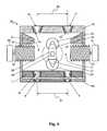
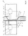
Fig. 1 is a front cut-away view of one embodiment of the multiple-fluid sourcing assembly;Fig. 2 is a side cut-away view of a first container/conduit assembly thereof;Fig. 3 is a front cross-sectional view of a first conduit thereof;Fig. 4 is a front cross-sectional view of an embodiment of a pumping assembly, with the pumping member in a loading position;Fig. 5 is a front cross-sectional view thereof, with the pumping member in a compressing position;Fig. 6 is a schematic view of an embodiment of a food dispenser;Fig. 7 is a front perspective view of an embodiment of a fluid mixing collector;Fig. 8 is a front cross-sectional view of an embodiment of a pumping assembly in the loading position, using a linear actuator;Fig. 9 is a front cross-sectional view of the pumping assembly thereof with a pinch member in the pumping position; andFig. 10 is a front cross-sectional view thereof with a pumping member in the pumping position.Figures 8-10 do not form part of the invention.- Referring to
Figs. 1 and2 , a preferred embodiment of the present invention is a multiple-fluid sourcing assembly 50 that includes first andsecond container members container members second container members second fluids - The preferred beverage is any beverage, hot or cold, that can be prepared from at least one concentrate, such as a syrup, a coffee concentrate, a cocoa concentrate, a milk concentrate, a tea concentrate, a juice concentrate, or a combination thereof. The concentrate is preferably mixed with a liquid, such as water, to produce the beverage suitable for consumption, such as a soft drink, a coffee drink, a tea drink, a juice, or a milk-based drink. Preferably, the beverages or beverage components include fluid concentrates. More preferably, the fluid concentrates include coffee or chocolate. In one embodiment, a coffee fluid-concentrate is used, which can include, for example, coffee solids, coffee aroma, and/or a whitener or dairy product.
- Preferably, first and
second conduits second container members respective conduits second container members conduits second nozzles fluid outlet members second container members second conduits - The
sourcing assembly 50 also includes a mountingmember 38 to which the first andsecond container members member 38 preferably includes ahousing 39, as shown inFig. 1 , that is configured to house the first andsecond container members container members respective conduits predetermined spacing 84 from each other. Thepredetermined spacing 84 is preferably dependent on the volume that the first andsecond container members predetermined spacing 84 is at least about 30 mm and is at most about 100 mm. More preferably, thepredetermined spacing 84 is about 50 mm to 70 mm. Theconduits predetermined value 84 therebetween. In this manner, thepredetermined spacing 84 between theconduits sourcing assembly 50 is loaded onto a pumping assembly. Alternatively, theconduits - The mounting
member 38 also includes a rigid plate member, which can be of unitary construction with thehousing 39 or a separate piece associated with thehousing 39. The rigid plate member is preferably configured to connect the first and secondfluid outlet members conduits member 38 includes a cardboard or plastic material, and the housing and rigid late member can be of unitary construction. - The preferred embodiment of the
first container member 42 and the associatedfluid outlet member 46 andconduit 44 are shown inFig. 2 . Thesecond container member 43, and the associatedfluid outlet member 47 andconduit 45 are preferably of a similar configuration. Theconduit 44 can be shorter than conduits generally used for food dispensers that include peristaltic pumps, since these typically require a sufficient length of tubing to wrap around the inside of a peristaltic-pump stator. The present arrangement can thus significantly reduce the amount of tubing that is required to dispense fluid, in some cases by over 45 inches as compared to typical peristaltic systems. - Preferably, the
container member 42,fluid outlet member 46, andconduit 44 are configured as a closed system that preferably is prepackaged as a single manipulatable structure, as shown inFig. 2 . More preferably, thesourcing assembly 50 comes prepackaged and includes the first andsecond container members member 38 and contained in thehousing 39. This advantageously prevents or reduces the risk of contamination of thefluids container members container member 42 and associatedconduit 44, or thesourcing assembly 50, can preferably be entirely disposable upon completion of dispensing, which avoids having to flush fluid remnants from the internal tubing of the dispenser as is typically required in previous food dispensers. - Referring to
Figs. 1 and3 , the first andsecond conduits upstream valves downstream valves second conduits compressible portion compressible portions compressible portions compressible portions compressible portions second nozzles downstream valves - The
upstream valves downstream valves compressible portion upstream valves downstream valves fluids downstream direction 85 out of thecontainer members valves Fig. 3 . Thevalves compressible portions first conduit 44, for example, the first upstream anddownstream check valves annular members inner cavities valve Upstream openings downstream openings valve first fluid 40 to pass through thecavities valve - Also preferably disposed within each
cavity ball members upstream openings ball members resilient member upstream openings first fluid 40 therethrough. - As the
compressible portion 32 is compressed, the pressure therein is increased to greater than atmospheric pressure. This positive pressure exerts a force on thedownstream ball member 74 of thedownstream valve 34, which causes the associatedresilient member 75 to compress. As theresilient member 75 compresses, theball member 74 moves in thedownstream direction 85 and allows thefirst fluid 40 to enter thecavity 71 through theupstream opening 72 and exit through thedownstream opening 73, and eventually exit thefirst conduit 44 through thenozzle 48. The increased pressure in thecompressible portion 32 also exerts a positive force on theupstream ball member 64 of theupstream valve 36, which, along with theresilient member 65, causes theupstream ball member 64 to bias towards the closed position to block theupstream opening 62 and impede the flow of thefirst fluid 40 therethrough. - Upon decompression of the
compressible portion 32, the pressure therein is reduced below atmospheric pressure, and this negative pressure and theresilient member 75 of thedownstream valve 34 is able to bias theball member 74 back against theupstream opening 72 to impede the flow of thefirst fluid 40 therethrough. With respect to theupstream valve 36, decompression of thecompressible portion 32 creates a negative pressure which acts on theupstream ball member 64 and causes the associatedresilient member 65 to compress. As theresilient member 65 compresses, theball member 64 moves in thedownstream direction 85 and allows the first fluid 40 from thefirst container member 42 to enter thecavity 61 through theupstream opening 62 and exit through thedownstream opening 63 into thecompressible portion 32. Advantageously, the act of compressing and decompressing the resilientcompressible portion 32, together with the opening and closing of the upstream anddownstream valves first fluid 40 to flow in substantially only thedownstream direction 85 through thefirst conduit 44. While the compression and decompression of only the firstcompressible portion 32 has been described herein, the secondcompressible portion 33, and its associated upstream anddownstream valves - Preferably, the spring-loaded, ball, check valves are about 40 to 60 mm in length, with an outside diameter of about 5 to 20 mm, and can cause local stretching of the conduit where placed. More preferably, the length of the check valves is about 45 to 55 mm, with an outside diameter of about 10 to 15 mm. Even more preferably, the length of the check valves is about 52 mm, with an outside diameter of about 13 mm. In other embodiments, the valves are molded of a thermoplastic material, and can be other types of valves, for example flapper valves. The valves can also be molded in the conduits as one piece.
- Alternatively, the first and second conduits can preferably include, respectively, only first and second compressible portions therein and first and second downstream valves disposed downstream thereof, with no upstream valves or backflow prevention members disposed between the compressible portions and the containers. Thus, when the first and second compressible portions are resiliently compressed, the first and second fluids therein are forced, respectively, downstream through the first and second downstream valves, and when the first and second compressible portions are decompressed, the first and second fluids, respectively, are drawn into the first and second compressible portions.
- To facilitate downstream flow of
fluids container members conduits sourcing assembly 50 can be brought toward a pumpingassembly 20 such that theconduits sourcing assembly 50 are disposed in respective first andsecond pumping spaces Figs. 4 and5 . Thepump assembly 20 includes apump housing 19. Preferably, thepump housing 19 is made of any suitable material such as a metal or plastic. Thepump housing 19 is configured to allow for a stable and easy connection between the sourcingassembly 50 and the pumpingassembly 20. Thepump housing 19 preferably includes a conduit guide, which includes an upper conduit guide 18 that is configured for guiding theconduits compressible portions member 28 of a pumping mechanism in therespective pumping spaces - In the preferred embodiment, the upper conduit guide 18 is configured for closely and stablely supporting the mounting
member 38. Preferably, the upper conduit guide 18 includes guide openings to receiveconduits upstream openings second conduits upstream openings conduits upstream openings downstream openings upstream openings conduits downstream openings predetermined spacing 83, which matches thepredetermined spacing 84, such that theconduits member 28 of the pumping mechanism. Preferably, the guide openings are conical or have another shape configured to guide theconduits member 28 of the pumping mechanism. - Advantageously, the upper conduit guide 18 allows for the easy and intuitive loading and unloading of the
sourcing assembly 50 from the pumpingassembly 20. During loading of thesourcing assembly 50, the user can "drop and load" theconduits spaces conduits upstream openings sourcing assembly 50 onto thepump assembly 20 to maintain a stable connection between the mountingmember 38 and theupper conduit guide 18. - In the preferred embodiment, the conduit guide also includes
intermediate guide members housing 19 above thecompression members intermediate guide members conduits spaces conduits predetermined spacing 83. The conduit guide also includes alower guide member 11, disposed below thecompression members openings conduits predetermined spacing 81, which preferably matches thepredetermined spacings pump housing 19 preferably includes first andsecond exit openings 8,9 configured to allowfluids assembly 20 through thenozzles - Preferably, the mounting
member 38 is associated with the upper conduit guide 18 such that the first and secondcompressible portions conduits member 28. The pumpingmember 28 is preferably rotatably mounted within thepump housing 19 over apump shaft 29. The pumpingmember 28 preferably includes at least onearm 26 on which is attached one ormore pump portion 24. Preferably, the pumpingmember 28 is configured such that itspump portion 24 can alternatingly and compressingly engage the first and secondcompressible portions second fluids Figs. 4 and5 , the pumpingmember 28 includes twoarms pump portions pump portions compressible portions member 28 includes twoarms compressible portions arms compressible portions pump portions member 28 rotates about the fixingmember 29. Alternatively, thearms - The preferred embodiment also includes a
pump motor 10 that is configured for rotating the pumpingmember 28. Preferably, the rate of rotation can be adjusted such that when pumpingmember 28 is set to a high rate of rotation, more fluid 40,41 can be pumped through theconduits pump motor 10 can preferably stop the pumping mechanism such that the pumpingmember 28 is stopped in a loading position as shown inFig. 4 . Advantageously, stopping the pumpingmember 28 in the loading position maintains a sufficient clearance in thepumping spaces fluid conduits assembly 20 for easy loading and unloading of thesourcing assembly 50 thereon. - The preferred embodiment also includes first and
second compression members pump housing 19, preferably substantially on opposite sides of the pumpingmember 28, and adjustably extend laterally to define the first andsecond pumping spaces member 28 is movable relative to thecompression members fluid conduits respective pumping spaces compression members pump portions second pumping spaces compression members compressible portions compression members Figs. 4 and5 , that can be screwed into and out of thepump housing 19. Additionally, thecompression members compression member motors compression members compression members - Referring to
Fig. 5 , the first and secondcompressible portions second pumping spaces member 28. When the pumpingmember 28 rotates, thepump portions compressible portions respective compression members second fluids container members pump portions compressible portions compression members fluid compressible portions - Moreover, the amount of
first fluid 40 that is dispensed from thefirst conduit 44, for example, can be varied independent of the amount ofsecond fluid 41 that is dispensed from thesecond conduit 45 by separately moving eachcompression member respective pumping space first compression member 22 is moved into thefirst pumping space 21, the more that the firstcompressible portion 32 will be compressed by thepump portions first fluid 40 will be dispensed from thefirst conduit 44. Importantly, thecompression members fluid conduit - The preferred embodiment also includes a motor controller that controls the
pump motor 10 and thecompression member motors pump motor 10 and thecompression member motors second fluids Fig. 6 shows one embodiment of the invention that includes a beverage dispenser having adispenser housing 100 that preferably contains afluid mixing collector 170 that collects the beverage components as they exit the pumpingassembly 20. The beverage dispenser also includes a multiple fluid-sourcing assembly 50 that is associated with a pumpingassembly 20 as previously described. Preferably, thefluid mixing collector 170 is disposed below thenozzles second conduits fluid mixing collector 170 preferably has an inclined bottom panel, as shown inFig. 7 , that allows the mixed beverage components to easily exit the collector. Preferably, the beverage dispenser also includes amixer 110 that receives the mixed beverage components from thefluid mixing collector 170.- The beverage dispenser also preferably includes a
liquid supply 80 that can be associated with apump 90. Preferably the liquid supply supplies water or another liquid 140 to dilute or mix the beverage components. The liquid 140 from theliquid supply 80 is preferably dispensed into themixer 110 for mixing with the beverage components to prepare a beverage. The beverage is then be dispensed from themixer 110, preferably passing through awhipper 120, and then into a servingcontainer 130 received at a servinglocation 82. In one embodiment, themixer 110 includes a heating or refrigeration element to heat or cool the mix ofbeverage components and liquid supply before dispensing - A pumping
assembly 120, which does not form part of the present invention, is shown inFigs. 8-10 . In this embodiment, the container housing and the first and second container members contained therein, as previously described, are associated with thepump housing 119. Thepump housing 119 preferably includes afirst pumping space 221 that is configured for receiving therein a firstcompressible portion 132 of afirst conduit 144. Thefirst conduit 144 preferably includes afirst valve 134 that is disposed downstream of the firstcompressible portion 132. Thefirst valve 134 is preferably a uni-directional valve, as previously described. Preferably, the pump housing also includes a second pumping space that is configured for receiving therein a second compressible portion of a second conduit. - A first pumping mechanism of the pumping
assembly 120 preferably includes a first linear actuator that is associated with thefirst pumping member 206 and thefirst pinch member 216 to move thefirst pumping member 206 andfirst pinch member 216 between loading and pumping positions. In the preferred embodiment, the first linear actuator preferably includes afirst pinch solenoid 212 and afirst pump solenoid 202. In other embodiments, the first pumping mechanism includes pneumatic or hydraulic mechanisms, or non-linear actuators or motors, for moving the first pumping member and first pinch member in the loading and pumping positions. - The
first pinch solenoid 212 is preferably associated with afirst pinch member 216 that is configured for pinching the firstcompressible portion 132 to close off, preferably substantially, the lumen therein to prevent the backflow of thefirst fluid 40 during pumping. In one embodiment, thefirst pinch solenoid 212 is disposed opposite thefirst pump solenoid 202 with respect to the firstcompressible portion 132. Thefirst pinch solenoid 212 is preferably associated with a firstpinch member axle 214, at the end of which is disposed afirst pinch disc 215. Thefirst pinch member 216 preferably extends from thefirst pinch disc 215 such that apinch portion 217 of thefirst pinch member 216 can be placed against one side of the firstcompressible portion 132. Thefirst pinch solenoid 212 is preferably configured for moving the firstpinch member axle 214 in the axial direction to position thefirst pinch member 216 in the loading and pumping position. - The
first pump solenoid 202 is preferably associated with a firstpump member axle 204, at the end of which is disposed thefirst pumping member 206. Thefirst pumping member 206 preferably includes a substantially flat face that is configured for engaging, associating with, and compressing the side wall of the firstcompressible portion 132. Thefirst pump solenoid 202 is preferably configured for moving the firstpump member axle 204 in an axial direction to position thefirst pumping member 206 in the loading and pumping position. - In the loading position shown in
Fig. 8 , thefirst pumping member 206 andfirst pinch member 216 are preferably disposed to allow the firstcompressible portion 132 of thefirst conduit 144 to be received in and removed from thefirst pumping space 221. More preferably, thefirst pumping member 206 andfirst pinch member 216 are disposed substantially clear of thefirst pumping space 221 to facilitate generally unimpeded reception and removal of the firstcompressible portion 132 of thefirst conduit 144 therein and therefrom, respectively. - In the pumping position shown in
Figs. 9 and10 , the first pinch solenoid preferably moves thefirst pinch member 216 to block the backflow of thefirst fluid 40 into the first container member, as shown inFig. 9 . Preferably, thefirst pinch solenoid 212 moves the firstpinch member axle 214 such that thefirst pinch member 216 is retracted through anopening 219 of thepump housing 119. Retraction of thefirst pinch member 216 causes thefirst pinch portion 217 to compress one side wall of the firstcompressible portion 132 against the other sidewall, thus closing the lumen thereof and preventing backflow of the first fluid therein. - The
first pump solenoid 202 then preferably moves the firstpump member axle 204 such that thefirst pumping member 206 engages and compresses against one side wall of the firstcompressible portion 132 in thefirst pumping space 221. Preferably, thefirst pumping member 206 compresses both side walls of the firstcompressible portion 132 against thewall 220 of the pumpinghousing 119, as shown inFig. 10 ., to pump thefirst fluid 40 through thefirst conduit 144. The amount that the firstcompressible portion 132 is compressed by thefirst pumping member 206 can also be varied, depending on the amount offirst fluid 40 that is to be pumped. After pumping, the first pinch and pump solenoids 212,202 preferably return, respectively, thefirst pinch member 216 and thefirst pumping member 206 to the loading position to allow thefirst fluid 40 to flow into the firstcompressible portion 132 from the first container. - The pumping
assembly 120 also preferably includes acontroller 208 that controls the first and second pumping mechanisms. Preferably, thecontroller 208 receives input from the user as to the type and size of beverage desired, and controls or adjusts the pumping mechanisms accordingly to vary the amounts of first and second fluids that are dispensed. For example, thecontroller 208 can vary the degree to which thefirst pumping member 206 compresses against the firstcompressible portion 132 in thefirst pumping space 221, thus varying the amount offirst fluid 40 that is pumped through thefirst conduit 144. Additionally, thecontroller 208 can vary the amount of iterations that thefirst pumping member 206 compresses against the firstcompressible portion 132. Thecontroller 208 also advantageously enables the pinch and pumping members of the first and second pumping mechanisms to be moved to and stopped in, preferably simultaneously, the loading position. - The pumping
assembly 120 can also preferably include a second pumping mechanism and associated second members that are similarly configured to the first pumping mechanism and first members previously described for pumping a second fluid from the second container member. - The term "about," as used herein, should generally be understood to refer to both numbers in a range of numerals. Moreover, all numerical ranges herein should be understood to include each whole integer within the range.
Claims (21)
- A multiple-fluid sourcing assembly comprising:- first and second container members (42, 43) containing first and second fluids, respectively;- first and second conduits (44, 45) in respective fluid communication with the first and second container members (42, 43) to allow the fluids to pass therethrough;- a mounting member to which the first and second container members (42, 43) are mounted such that the first and second conduits (44, 45) are disposed at a predetermined spacing from each other;wherein the first conduit (44) comprises a first compressible portion (38) and a first downstream valve (34) in the first conduit (44) disposed downstream of the first compressible portion (32) and configured to allow the first fluid to flow substantially only downstream of the first downstream valve (34), the first compressible portion (32) being resiliently compressible such that fluid therein is forced downstream through the first downstream valve (34) when the first compressible portion is compressed, with the first compressible portion being resiliently biased towards an uncompressed state to draw the first fluid into the first compressible portion when the first compressible portion is decompressed; and
wherein the second conduit (45) comprises a second compressible portion that is compressible to pump the second fluid therethrough from the second container member (43); and
the spacing between the first and second conduits (44, 45) is selected such that the both compressible portions (32, 33) are compressible by a pumping mechanism (20) said pumping mechanism (20) comprises a pumping member (28) disposed between the first and second compressible portions (32, 33),
characterised in that the pumping mechanism (20) is configured to rotatably engage the first and the second compressible portions (32, 33) and configured to alternatingly compress the first and the second compressible portions simultaneously and then decompress the first and the second compressible portions simultaneously. - The multiple-fluid sourcing assembly of claim 1, wherein the first and second conduits have a length of less than about 200 mm.
- The multiple-fluid sourcing assembly of claim 1 or 2, further comprising : a first backflow prevention member in the first conduit configured to allow the first fluid to flow substantially only out of the first container; wherein the first compressible portion is disposed between the first backflow prevention member and the first downstream valve, and wherein when the first compressible portion is resiliently biased towards an uncompressed state to draw the first fluid thereinto, fluid is forced through the first backflow prevention member.
- The multiple-fluid sourcing assembly of claim 3, further comprising : a second backflow prevention member in the second conduit configured to allow the second fluid to flow substantially only downstream, out from the second container; and a second downstream valve in the second conduit disposed downstream of the second backflow prevention member and configured to allow the second fluid to flow substantially only downstream; wherein the second compressible portion is disposed between the second backflow prevention member and the second downstream valve, the second compressible portion being resiliently compressible such that fluid therein is forced downstream through the second downstream valve when the second compressible portion is compressed, the second compressible portion being resiliently biased towards an uncompressed state to draw the second fluid thereinto through the first backflow prevention member when the second compressible portion is decompressed.
- The multiple-fluid sourcing assembly of claim 4, wherein the first and second backflow prevention members comprise, respectively, first and second upstream valves.
- The multiple-fluid sourcing assembly of claim 1 or 2, wherein the first and second conduits are free of any upstream valve disposed respectively therein, between the first container and the first compressible portion or between the second container and the second compressible portion.
- The multiple-fluid sourcing assembly of claim 5, wherein the spacing between the first and second conduits is selected to enable a single pumping member of the pumping mechanism to concurrently pump both the first and second fluids by compressing the first and second compressible portions.
- The multiple-fluid sourcing assembly of any one of the preceding claims, wherein the first and second conduits are positioned substantially parallel to each other to leave a spacing of predetermined value.
- The multiple-fluid sourcing assembly of any one of the preceding claims, wherein the conduits comprise flexible tubing and wherein the fluids are food products.
- The multiple-fluid sourcing assembly of any one of the preceding claims, wherein the mounting member comprises a housing that houses both the first and second container members.
- The multiple-fluid sourcing assembly of any one of the preceding claims, wherein the first and second container members comprise, respectively, a first and second fluid outlet members that are in fluid communication with, respectively, the first and second conduits.
- The multiple-fluid sourcing assembly of claim 11, wherein the mounting member comprises a rigid plate member that connects the first outlet member and the second outlet member, the rigid plate member being for maintaining a predetermined spacing between the conduits.
- A dispensing system, comprising: the multiple-fluid sourcing assembly of claims 4, 5 or 7; wherein the first and second backflow prevention members comprise, respectively, first and second pinch members configured to pinch the first and second compressible portions to substantially block the backflow of the first and second fluids upstream of the compressible portions.
- The dispensing system of claim 13, further comprising a conduit guide configured for guiding the conduits for placement of the compressible portions in pumpable association with the pumping mechanism.
- The dispensing system of claim 14, wherein the conduit guide defines an upstream opening configured to facilitate reception therein of the conduits which is larger than at least a portion of the conduit guide disposed downstream of the upstream opening to position the conduits in the pumpable association.
- The dispensing system of claim 13, further comprising first and second compression members disposed adjacent the pumping member to define first and second pumping spaces between the pumping member and the compression members, wherein the first and second compressible portions are placed in the first and second pumping spaces, respectively, in the pumpable association, the pumping member being configured to compress the compressible portions against the compression members to pump the first and second fluids from the container members.
- The dispensing system of claim 16, wherein the compressible members and pumping member are movable relative to each other to change the size of the pumping spaces.
- The dispensing system of claim 16 or 17, further comprising a pump- member control configured for stopping the pumping member in a stopped position to maintain a sufficient clearance in the pumping spaces for generally unimpeded reception of the fluid conduits therein.
- The dispensing system of claim 13, wherein the dispensing system is a beverage dispenser, and the first and second fluid sources are beverage components, the dispenser being configured for mixing the components to prepare and dispense a beverage.
- The dispensing system of claim 09, further comprising a fluid mixing collector placed below the beverage components to receive the components and mix the components.
- A method of simultaneously dispensing fluids from first and second container members (42, 43), which comprises reciprocating a pumping portion of a pumping member (20) alternatingly against first and second compressible conduit portions (32, 33) said pumping mechanism being configured to rotatably engage the first and the second compressible portions (32, 33), to alternatingly compress the first and second compressible conduit portions simultaneously and decompress the first and second compressible conduit portions simultaneously, with the decompressing of the compressible conduit portions drawing in fluids through backflow prevention members (46, 47) in fluid communication with the compressible conduit portions and causing downstream valves (34, 35) in fluid communication with the compressible conduit portions to close, and with the compressing of the compressible conduit portions forcing the fluid through the downstream valves and causing the backflow prevention members to close,
Applications Claiming Priority (2)
| Application Number | Priority Date | Filing Date | Title |
|---|---|---|---|
| US11/232,962US7651010B2 (en) | 2005-09-23 | 2005-09-23 | Food dispenser with pump for dispensing from a plurality of sources |
| PCT/EP2006/065533WO2007039347A2 (en) | 2005-09-23 | 2006-08-22 | Food dispenser with pump for dispensing from a plurality of sources |
Publications (2)
| Publication Number | Publication Date |
|---|---|
| EP1940728A2 EP1940728A2 (en) | 2008-07-09 |
| EP1940728B1true EP1940728B1 (en) | 2012-12-26 |
Family
ID=37768689
Family Applications (1)
| Application Number | Title | Priority Date | Filing Date |
|---|---|---|---|
| EP06792923ANot-in-forceEP1940728B1 (en) | 2005-09-23 | 2006-08-22 | Food dispenser with pump for dispensing from a plurality of sources |
Country Status (7)
| Country | Link |
|---|---|
| US (1) | US7651010B2 (en) |
| EP (1) | EP1940728B1 (en) |
| JP (1) | JP5305911B2 (en) |
| AU (1) | AU2006298912B2 (en) |
| CA (1) | CA2623173A1 (en) |
| ES (1) | ES2400918T3 (en) |
| WO (1) | WO2007039347A2 (en) |
Cited By (1)
| Publication number | Priority date | Publication date | Assignee | Title |
|---|---|---|---|---|
| EP3536957A4 (en)* | 2016-11-02 | 2020-07-01 | Suntory Holdings Limited | PUMP MECHANISM AND BEVERAGE DISPENSER |
Families Citing this family (67)
| Publication number | Priority date | Publication date | Assignee | Title |
|---|---|---|---|---|
| US9518899B2 (en) | 2003-08-11 | 2016-12-13 | Sakura Finetek U.S.A., Inc. | Automated reagent dispensing system and method of operation |
| US20070068966A1 (en)* | 2005-09-23 | 2007-03-29 | Orzech Thomas S | Food dispenser with pump for easy loading of containers therein |
| US8459509B2 (en)* | 2006-05-25 | 2013-06-11 | Sakura Finetek U.S.A., Inc. | Fluid dispensing apparatus |
| US8162176B2 (en)* | 2007-09-06 | 2012-04-24 | The Coca-Cola Company | Method and apparatuses for providing a selectable beverage |
| US8464909B2 (en)* | 2007-11-07 | 2013-06-18 | Nestec S.A. | Dispensing system for food products |
| US8261941B2 (en)* | 2008-06-13 | 2012-09-11 | American Sterilizer Company | Fluid dispenser |
| DE102008002957A1 (en)* | 2008-07-22 | 2010-01-28 | Evonik Stockhausen Gmbh | Dispensing system for the portion-wise dispensing of pasty, liquid, gaseous and / or foamed media |
| US8186973B2 (en)* | 2008-08-14 | 2012-05-29 | Euro-Pro Operating Llc | Tubular pump |
| EP2168468B1 (en) | 2008-09-24 | 2011-04-06 | Nestec S.A. | Device for In-cup-preparation of a beverage |
| ITFI20080198A1 (en)* | 2008-10-15 | 2010-04-16 | Saeco Ipr Ltd | "COFFEE MACHINE'" |
| US8276784B2 (en)* | 2008-12-11 | 2012-10-02 | Gojo Industries, Inc. | Pressure activated automatic source switching dispenser system |
| US20100243087A1 (en)* | 2009-03-03 | 2010-09-30 | Millipore Corporation | System and pump apparatus for processing fluid samples |
| EP2256071A1 (en)* | 2009-05-28 | 2010-12-01 | SPX APV Danmark A/S | Powder material intake device and method for taking powder material into a liquid |
| GB0915826D0 (en)* | 2009-09-10 | 2009-10-07 | Imi Cornelius Uk Ltd | Foodstuff dispenser |
| US8870025B2 (en)* | 2009-10-23 | 2014-10-28 | Nestec S.A. | Method and device for aseptically dispensing multiple portions of a fluid |
| MX2012004698A (en)* | 2009-10-23 | 2012-08-31 | Nestec Sa | Method and device for aseptically dispensing multiple portions of a fluid. |
| US8881948B1 (en)* | 2009-11-24 | 2014-11-11 | Food Equipment Technologies Company, Inc. | Liquid beverage concentrate mixing beverage dispenser and method |
| NL2003977C2 (en)* | 2009-12-18 | 2011-06-21 | Bravilor Holding Bv | BEVERAGE PREPARATION DEVICE FITTED WITH A LIQUID DISTRIBUTOR. |
| EA022042B1 (en) | 2009-12-22 | 2015-10-30 | Унилевер Н.В. | Beverage dispenser with water cooler |
| MX2012007231A (en) | 2009-12-22 | 2012-07-25 | Unilever Nv | Beverage dispenser with water cooler and concentrate adding device. |
| US8308278B2 (en) | 2010-04-02 | 2012-11-13 | Xerox Corporation | System and method for operating a conduit to transport fluid through the conduit |
| US8857666B2 (en)* | 2010-04-15 | 2014-10-14 | Edward L. O'Keefe, JR. | Wine dispensing system |
| EP2383553A1 (en)* | 2010-04-30 | 2011-11-02 | Nestec S.A. | Package for storing and dosing a fluid |
| US8277196B2 (en)* | 2010-06-11 | 2012-10-02 | Tyco Healthcare Group Lp | Adaptive accuracy for enteral feeding pump |
| US8689439B2 (en) | 2010-08-06 | 2014-04-08 | Abbott Laboratories | Method for forming a tube for use with a pump delivery system |
| US8377000B2 (en) | 2010-10-01 | 2013-02-19 | Abbott Laboratories | Enteral feeding apparatus having a feeding set |
| US8377001B2 (en) | 2010-10-01 | 2013-02-19 | Abbott Laboratories | Feeding set for a peristaltic pump system |
| CN102452094A (en) | 2010-10-28 | 2012-05-16 | 吉列公司 | Hair removing kit for distributing liquid |
| CN102452085B (en) | 2010-10-28 | 2016-01-27 | 吉列公司 | For the pump of the hair removal device of dispense liquid |
| CN102452092B (en) | 2010-10-28 | 2015-04-01 | 吉列公司 | Hair removing device for dispensing liquid |
| CN102452091B (en) | 2010-10-28 | 2015-08-12 | 吉列公司 | For the application device with deflector of hair removal device |
| CN102452095B (en) | 2010-10-28 | 2014-10-29 | 吉列公司 | Applicator of hair removing device for distributing liquid |
| CN102452088B (en) | 2010-10-28 | 2015-07-01 | 吉列公司 | Hair removing device with blade holder holding covering part |
| US8640931B2 (en)* | 2011-02-01 | 2014-02-04 | Emerald Wine Systems, LLC | Tri-function tap for beverages |
| US8752732B2 (en)* | 2011-02-01 | 2014-06-17 | Sakura Finetek U.S.A., Inc. | Fluid dispensing system |
| US8903228B2 (en)* | 2011-03-09 | 2014-12-02 | Chong Corporation | Vapor delivery devices and methods |
| US9399110B2 (en) | 2011-03-09 | 2016-07-26 | Chong Corporation | Medicant delivery system |
| CA2830768A1 (en)* | 2011-03-30 | 2012-10-04 | Nestec S.A. | Beverage dispenser with improved nozzles assembly |
| US20120248149A1 (en)* | 2011-03-30 | 2012-10-04 | Gojo Industries, Inc. | Liquid dispenser |
| TW201332818A (en)* | 2011-09-07 | 2013-08-16 | Gojo Ind Inc | Wiper foam pump, refill unit & dispenser for same |
| US8580568B2 (en) | 2011-09-21 | 2013-11-12 | Sakura Finetek U.S.A., Inc. | Traceability for automated staining system |
| US8932543B2 (en) | 2011-09-21 | 2015-01-13 | Sakura Finetek U.S.A., Inc. | Automated staining system and reaction chamber |
| US9156175B2 (en) | 2011-12-09 | 2015-10-13 | The Gillette Company | Fluid applicator for a personal-care appliance |
| JP5904639B2 (en)* | 2012-04-27 | 2016-04-13 | 国立大学法人東京工業大学 | 3 port valve |
| FR2998889B1 (en) | 2012-12-04 | 2015-01-02 | Gervais Danone Sa | COMPACT APPARATUS FOR PRESERVING AND DISPENSING A FOOD PRODUCT, IN PARTICULAR A YOGHURT |
| US9695033B1 (en)* | 2013-10-17 | 2017-07-04 | Andrew Alshouse | System for dispensing custom blended electronic cigarette liquid |
| GB201321295D0 (en)* | 2013-12-03 | 2014-01-15 | Hodges & Drake Design Ltd | Apparatus for dispensing a flavour alcoholic beverage |
| US11284748B2 (en) | 2014-09-09 | 2022-03-29 | Chowbotics | Enhanced automated food making apparatus |
| US10813503B2 (en) | 2014-09-09 | 2020-10-27 | Casabots Inc. | Automated food making apparatus |
| US11918150B2 (en) | 2014-09-09 | 2024-03-05 | DoorDash, Inc. | Enhanced automated food making apparatus |
| LT3265421T (en)* | 2015-03-04 | 2020-06-10 | Sodastream Industries Ltd. | DOSAGE SYSTEM |
| JP6906889B2 (en)* | 2015-03-19 | 2021-07-21 | サントリーホールディングス株式会社 | Liquid dispenser |
| JP6595244B2 (en)* | 2015-03-19 | 2019-10-23 | サントリーホールディングス株式会社 | container |
| WO2016148220A1 (en)* | 2015-03-19 | 2016-09-22 | サントリーホールディングス株式会社 | Container |
| CN105270658A (en)* | 2015-10-27 | 2016-01-27 | 长安大学 | Drying agent filling device |
| ES2939370T3 (en)* | 2016-01-12 | 2023-04-21 | Freezio Ag | Dispensing system with cartridge holder |
| US20170252994A1 (en)* | 2016-03-03 | 2017-09-07 | Juicero, Inc. | Juicing system with juicer cartridge restraints |
| US20170253000A1 (en)* | 2016-03-03 | 2017-09-07 | Juicero, Inc. | Juicer with locking mechanism |
| ITUA20162443A1 (en)* | 2016-04-08 | 2017-10-08 | Laica Spa | DEVICE FOR THE PREPARATION OF DRINKS |
| US11391272B2 (en)* | 2016-06-13 | 2022-07-19 | Graco Minnesota Inc. | Mechanical tubular diaphragm pump having a housing with upstream and downstream check valves fixed thereto at either end of a resilient tube forming a fluid pathway wherein the tube is depressed by a depressor configured to be moved by a motorized reciprocating unit |
| KR102519052B1 (en)* | 2016-07-19 | 2023-04-07 | 삼성전자주식회사 | Valve assembly and refrigerator having the same |
| JP6815827B2 (en)* | 2016-10-26 | 2021-01-20 | サントリーホールディングス株式会社 | Pour pump and liquid dispenser |
| US11969935B2 (en)* | 2016-12-07 | 2024-04-30 | President And Fellows Of Harvard College | Valved nozzle with a compensator and massively parallel 3D printing system |
| FI3589169T3 (en)* | 2017-04-04 | 2024-12-16 | Doordash Inc | An enhanced automated food making apparatus |
| IT201900006833A1 (en)* | 2019-05-14 | 2020-11-14 | Soremartec Sa | DISPENSER GROUP FOR A FOOD CREAM DOSING MACHINE |
| US11602589B2 (en)* | 2019-05-21 | 2023-03-14 | Covidien Lp | Peristaltic pumps with selective activation of multiple fluid lines and fluid management systems including the same |
| US20210212903A1 (en)* | 2020-01-15 | 2021-07-15 | Christopher O'Keefe | Feed and flush delivery device |
Family Cites Families (47)
| Publication number | Priority date | Publication date | Assignee | Title |
|---|---|---|---|---|
| US3127845A (en)* | 1960-10-03 | 1964-04-07 | Carl S Voelcker | Pump design |
| US3604418A (en)* | 1969-03-10 | 1971-09-14 | Young C Jones | Apparatus for stripping fluid from flexible plastic tubing |
| US3518033A (en)* | 1969-08-22 | 1970-06-30 | Robert M Anderson | Extracorporeal heart |
| JPS5224251Y2 (en)* | 1972-08-03 | 1977-06-02 | ||
| US4042153A (en)* | 1973-03-14 | 1977-08-16 | Standard Oil Company | Liquid dropping device |
| US3881846A (en)* | 1973-08-06 | 1975-05-06 | Outboard Marine Corp | Fluid pump with resilient pumping membrane |
| US3881641A (en)* | 1973-10-31 | 1975-05-06 | Illinois Tool Works | Dispensing device |
| IE47040B1 (en)* | 1977-08-08 | 1983-11-30 | Douwe Egberts Tabaksfab | Concentrate container and apparatus for dispensing concenttrates |
| GR76098B (en) | 1981-05-25 | 1984-08-03 | Douwe Egberts Tabaksfab | |
| US4407436A (en)* | 1982-02-25 | 1983-10-04 | Broadfoot John T | Metering and/or feeding device for materials |
| NL8204867A (en)* | 1982-12-16 | 1984-07-16 | Douwe Egberts Tabaksfab | ELECTROMAGNETIC DOSING DEVICE WITH ASYMMETRICAL LEVERS. |
| US4500269A (en)* | 1983-11-30 | 1985-02-19 | Cormed, Inc. | Integral tube-loading assembly for peristaltic pump |
| CA1179992A (en)* | 1984-02-13 | 1984-12-27 | Michael Bell | Milk dispenser |
| IT8453709U1 (en)* | 1984-08-07 | 1986-02-07 | Hospal Dasco Spa | IMPROVED APPARATUS FOR CIRCULATION OF A LIQUID ALONG A TUBULAR LINE. |
| JPS6278381U (en)* | 1986-08-21 | 1987-05-19 | ||
| US5105992A (en)* | 1988-07-05 | 1992-04-21 | Fender Franklin D | Soapdispenser having a squeeze pump |
| JPH02104991A (en)* | 1988-10-13 | 1990-04-17 | S G:Kk | Linear tubing pump |
| US4967940A (en)* | 1989-02-21 | 1990-11-06 | Minnesota Mining And Manufacturing Co. | Method and apparatus for precision squeeze tube valving, pumping and dispensing of work fluid(s) |
| US5033943A (en)* | 1990-01-08 | 1991-07-23 | Eldex Laboratories, Inc. | Low fluid shear pump |
| DE4008705A1 (en)* | 1990-03-17 | 1991-09-19 | Varta Batterie | DEVICE FOR IMPLEMENTING VISCOSIC ACTIVE INGREDIENTS INTO THE HOUSING OF A GALVANIC ELEMENT |
| US5242081A (en)* | 1990-04-03 | 1993-09-07 | Lever Brothers Company, Division Of Conopco, Inc. | Dual liquid dispensing system |
| US5118011A (en)* | 1990-12-05 | 1992-06-02 | Oatey Co. | Food roller dispenser |
| US5255822A (en)* | 1991-12-09 | 1993-10-26 | M & D International Enterprises, Inc. | Automatic soap dispenser |
| US5316452A (en)* | 1992-05-11 | 1994-05-31 | Gilbert Corporation | Dispensing assembly with interchangeable cartridge pumps |
| DE4241073C1 (en)* | 1992-12-05 | 1994-06-01 | Satzinger Gmbh & Co | Dispensing system for dosed discharge esp. of lubricant fluid - has container in which fluid is acted on by gas pressure produced in container and dosing pump connected to container |
| US5377871A (en)* | 1993-01-04 | 1995-01-03 | Marlingford Holdings Limited | Dispenser having roller for dispensing fluid from a collapsible bag |
| US5353963A (en)* | 1993-06-02 | 1994-10-11 | Karma, Inc. | Post mix dispenser |
| SE505827C2 (en)* | 1993-09-07 | 1997-10-13 | Asept Int Ab | Serving device for portioning out liquid foods from a food container |
| US5577891A (en)* | 1993-11-30 | 1996-11-26 | Instech Laboratories, Inc. | Low power portable resuscitation pump |
| US5611465A (en)* | 1995-03-20 | 1997-03-18 | Lee; Kuo-Chou | Automatic toilet bowl cleaner |
| JP3186577B2 (en)* | 1996-03-27 | 2001-07-11 | 三浦工業株式会社 | Liquid ejection device |
| IT1283326B1 (en)* | 1996-03-27 | 1998-04-16 | Corob Srl | SYSTEM FOR THE STORAGE, TRANSPORT AND DISPENSING OF COLORING PRODUCTS AS WELL AS TANK AND DISPENSING MACHINE |
| JP3588187B2 (en)* | 1996-04-02 | 2004-11-10 | 三洋電機株式会社 | Combined beverage dispenser |
| US6003733A (en)* | 1996-07-22 | 1999-12-21 | Compass Worldwide | Apparatus for the dispensing of heated viscous food product |
| US5797519A (en)* | 1997-03-14 | 1998-08-25 | The Coca-Cola Company | Postmix beverage dispenser |
| JPH1130186A (en)* | 1997-07-10 | 1999-02-02 | Fuji Electric Co Ltd | Tube type pump device for BIB type beverage dispenser |
| FR2771721B1 (en)* | 1997-12-02 | 2000-02-18 | Lucien Vidal | DEVICE FOR PNEUMATICALLY TRANSPORTING MATERIAL SUCH AS CONCRETE |
| JPH11245997A (en)* | 1998-02-27 | 1999-09-14 | Sanyo Electric Co Ltd | Drink dispenser |
| US6016935A (en)* | 1998-08-01 | 2000-01-25 | Star Manufacturing International, Inc. | Viscous food dispensing and heating/cooling assembly and method |
| US6756069B2 (en)* | 1999-05-18 | 2004-06-29 | Nestec S.A. | System and method for dispensing a liquid beverage concentrate |
| US6196420B1 (en)* | 1999-09-09 | 2001-03-06 | Nestec S.A. | Pumpless dispenser for viscous food products |
| JP2001263260A (en)* | 2000-03-15 | 2001-09-26 | Noiberuku Kk | Pump |
| US6454133B1 (en) | 2001-05-03 | 2002-09-24 | Kenneth Oscar Lopez | Toothpaste butler |
| US6445133B1 (en)* | 2001-07-23 | 2002-09-03 | Litetronics International, Inc. | Incandescent lamp with integral voltage converter |
| US6659309B2 (en)* | 2001-12-05 | 2003-12-09 | International Dispensing Corporation | Portion control dispenser |
| US20060249536A1 (en)* | 2005-05-09 | 2006-11-09 | Hartman Eric E | Device and method for dispensing a food product using a reclosable resilient valve |
| US20070000947A1 (en)* | 2005-07-01 | 2007-01-04 | Lewis Russell H | Apparatus and methods for dispensing fluidic or viscous materials |
- 2005
- 2005-09-23USUS11/232,962patent/US7651010B2/ennot_activeExpired - Fee Related
- 2006
- 2006-08-22ESES06792923Tpatent/ES2400918T3/enactiveActive
- 2006-08-22CACA002623173Apatent/CA2623173A1/ennot_activeAbandoned
- 2006-08-22AUAU2006298912Apatent/AU2006298912B2/ennot_activeCeased
- 2006-08-22EPEP06792923Apatent/EP1940728B1/ennot_activeNot-in-force
- 2006-08-22JPJP2008531644Apatent/JP5305911B2/ennot_activeExpired - Fee Related
- 2006-08-22WOPCT/EP2006/065533patent/WO2007039347A2/enactiveApplication Filing
Cited By (1)
| Publication number | Priority date | Publication date | Assignee | Title |
|---|---|---|---|---|
| EP3536957A4 (en)* | 2016-11-02 | 2020-07-01 | Suntory Holdings Limited | PUMP MECHANISM AND BEVERAGE DISPENSER |
Also Published As
| Publication number | Publication date |
|---|---|
| US7651010B2 (en) | 2010-01-26 |
| EP1940728A2 (en) | 2008-07-09 |
| AU2006298912A1 (en) | 2007-04-12 |
| WO2007039347A2 (en) | 2007-04-12 |
| US20070068969A1 (en) | 2007-03-29 |
| HK1123028A1 (en) | 2009-06-05 |
| JP2009508775A (en) | 2009-03-05 |
| WO2007039347A3 (en) | 2007-11-29 |
| AU2006298912B2 (en) | 2011-05-12 |
| ES2400918T3 (en) | 2013-04-15 |
| CA2623173A1 (en) | 2007-04-12 |
| JP5305911B2 (en) | 2013-10-02 |
Similar Documents
| Publication | Publication Date | Title |
|---|---|---|
| EP1940728B1 (en) | Food dispenser with pump for dispensing from a plurality of sources | |
| US20100258590A1 (en) | Food dispenser with pump for easy loading of containers therein | |
| CN1984837B (en) | System and device for preparing and dispensing a product from a mixture made of a base liquid and a diluent | |
| AU2010233811B2 (en) | Mixing nozzle fitment and mixed liquid dispenser | |
| EP2232074B1 (en) | Peristaltic pump | |
| US7337920B2 (en) | Fluid dispensing apparatus | |
| CN106458376A (en) | Scalable modular system and method for storing, preserving, managing, and selectively dispensing beverages | |
| EP2383553A1 (en) | Package for storing and dosing a fluid | |
| EP2925665B1 (en) | Beverage dispensing system | |
| CN108289565A (en) | Beverage dispenser system and method | |
| AU2009354185B2 (en) | Method and device for aseptically dispensing multiple portions of a fluid | |
| CN118021146A (en) | Raw material conveying device for conveying liquid raw material with viscosity coefficient higher than that of water, and related discharge amount detecting device and flow stabilizing device | |
| HK1123028B (en) | Food dispenser with pump for dispensing from a plurality of sources | |
| EP2039650A1 (en) | Multiple beverage dispensing unit | |
| GB2602620A (en) | Pump | |
| WO2023028234A1 (en) | Flavor infusion dispenser | |
| CN110950295A (en) | Beverage Delivery System |
Legal Events
| Date | Code | Title | Description |
|---|---|---|---|
| PUAI | Public reference made under article 153(3) epc to a published international application that has entered the european phase | Free format text:ORIGINAL CODE: 0009012 | |
| 17P | Request for examination filed | Effective date:20080529 | |
| AK | Designated contracting states | Kind code of ref document:A2 Designated state(s):AT BE BG CH CY CZ DE DK EE ES FI FR GB GR HU IE IS IT LI LT LU LV MC NL PL PT RO SE SI SK TR | |
| RIN1 | Information on inventor provided before grant (corrected) | Inventor name:MURPHY, RICHARD LUKE Inventor name:ORZECH, THOMAS SCOTT Inventor name:FOG, STEPHEN C. | |
| REG | Reference to a national code | Ref country code:HK Ref legal event code:DE Ref document number:1123028 Country of ref document:HK | |
| 17Q | First examination report despatched | Effective date:20110721 | |
| DAX | Request for extension of the european patent (deleted) | ||
| GRAP | Despatch of communication of intention to grant a patent | Free format text:ORIGINAL CODE: EPIDOSNIGR1 | |
| GRAS | Grant fee paid | Free format text:ORIGINAL CODE: EPIDOSNIGR3 | |
| GRAA | (expected) grant | Free format text:ORIGINAL CODE: 0009210 | |
| AK | Designated contracting states | Kind code of ref document:B1 Designated state(s):AT BE BG CH CY CZ DE DK EE ES FI FR GB GR HU IE IS IT LI LT LU LV MC NL PL PT RO SE SI SK TR | |
| REG | Reference to a national code | Ref country code:GB Ref legal event code:FG4D | |
| REG | Reference to a national code | Ref country code:CH Ref legal event code:EP | |
| REG | Reference to a national code | Ref country code:AT Ref legal event code:REF Ref document number:590339 Country of ref document:AT Kind code of ref document:T Effective date:20130115 | |
| REG | Reference to a national code | Ref country code:DE Ref legal event code:R096 Ref document number:602006033863 Country of ref document:DE Effective date:20130228 | |
| REG | Reference to a national code | Ref country code:SE Ref legal event code:TRGR | |
| REG | Reference to a national code | Ref country code:ES Ref legal event code:FG2A Ref document number:2400918 Country of ref document:ES Kind code of ref document:T3 Effective date:20130415 | |
| PG25 | Lapsed in a contracting state [announced via postgrant information from national office to epo] | Ref country code:LT Free format text:LAPSE BECAUSE OF FAILURE TO SUBMIT A TRANSLATION OF THE DESCRIPTION OR TO PAY THE FEE WITHIN THE PRESCRIBED TIME-LIMIT Effective date:20121226 Ref country code:FI Free format text:LAPSE BECAUSE OF FAILURE TO SUBMIT A TRANSLATION OF THE DESCRIPTION OR TO PAY THE FEE WITHIN THE PRESCRIBED TIME-LIMIT Effective date:20121226 | |
| REG | Reference to a national code | Ref country code:NL Ref legal event code:T3 | |
| REG | Reference to a national code | Ref country code:AT Ref legal event code:MK05 Ref document number:590339 Country of ref document:AT Kind code of ref document:T Effective date:20121226 | |
| REG | Reference to a national code | Ref country code:GR Ref legal event code:EP Ref document number:20130400547 Country of ref document:GR Effective date:20130418 | |
| REG | Reference to a national code | Ref country code:LT Ref legal event code:MG4D | |
| PG25 | Lapsed in a contracting state [announced via postgrant information from national office to epo] | Ref country code:SI Free format text:LAPSE BECAUSE OF FAILURE TO SUBMIT A TRANSLATION OF THE DESCRIPTION OR TO PAY THE FEE WITHIN THE PRESCRIBED TIME-LIMIT Effective date:20121226 Ref country code:LV Free format text:LAPSE BECAUSE OF FAILURE TO SUBMIT A TRANSLATION OF THE DESCRIPTION OR TO PAY THE FEE WITHIN THE PRESCRIBED TIME-LIMIT Effective date:20121226 | |
| PG25 | Lapsed in a contracting state [announced via postgrant information from national office to epo] | Ref country code:CZ Free format text:LAPSE BECAUSE OF FAILURE TO SUBMIT A TRANSLATION OF THE DESCRIPTION OR TO PAY THE FEE WITHIN THE PRESCRIBED TIME-LIMIT Effective date:20121226 Ref country code:IS Free format text:LAPSE BECAUSE OF FAILURE TO SUBMIT A TRANSLATION OF THE DESCRIPTION OR TO PAY THE FEE WITHIN THE PRESCRIBED TIME-LIMIT Effective date:20130426 Ref country code:BG Free format text:LAPSE BECAUSE OF FAILURE TO SUBMIT A TRANSLATION OF THE DESCRIPTION OR TO PAY THE FEE WITHIN THE PRESCRIBED TIME-LIMIT Effective date:20130326 Ref country code:SK Free format text:LAPSE BECAUSE OF FAILURE TO SUBMIT A TRANSLATION OF THE DESCRIPTION OR TO PAY THE FEE WITHIN THE PRESCRIBED TIME-LIMIT Effective date:20121226 Ref country code:AT Free format text:LAPSE BECAUSE OF FAILURE TO SUBMIT A TRANSLATION OF THE DESCRIPTION OR TO PAY THE FEE WITHIN THE PRESCRIBED TIME-LIMIT Effective date:20121226 Ref country code:CY Free format text:LAPSE BECAUSE OF FAILURE TO SUBMIT A TRANSLATION OF THE DESCRIPTION OR TO PAY THE FEE WITHIN THE PRESCRIBED TIME-LIMIT Effective date:20121226 Ref country code:EE Free format text:LAPSE BECAUSE OF FAILURE TO SUBMIT A TRANSLATION OF THE DESCRIPTION OR TO PAY THE FEE WITHIN THE PRESCRIBED TIME-LIMIT Effective date:20121226 Ref country code:BE Free format text:LAPSE BECAUSE OF FAILURE TO SUBMIT A TRANSLATION OF THE DESCRIPTION OR TO PAY THE FEE WITHIN THE PRESCRIBED TIME-LIMIT Effective date:20121226 | |
| PG25 | Lapsed in a contracting state [announced via postgrant information from national office to epo] | Ref country code:RO Free format text:LAPSE BECAUSE OF FAILURE TO SUBMIT A TRANSLATION OF THE DESCRIPTION OR TO PAY THE FEE WITHIN THE PRESCRIBED TIME-LIMIT Effective date:20121226 Ref country code:PL Free format text:LAPSE BECAUSE OF FAILURE TO SUBMIT A TRANSLATION OF THE DESCRIPTION OR TO PAY THE FEE WITHIN THE PRESCRIBED TIME-LIMIT Effective date:20121226 Ref country code:PT Free format text:LAPSE BECAUSE OF FAILURE TO SUBMIT A TRANSLATION OF THE DESCRIPTION OR TO PAY THE FEE WITHIN THE PRESCRIBED TIME-LIMIT Effective date:20130426 | |
| REG | Reference to a national code | Ref country code:HK Ref legal event code:GR Ref document number:1123028 Country of ref document:HK | |
| PG25 | Lapsed in a contracting state [announced via postgrant information from national office to epo] | Ref country code:DK Free format text:LAPSE BECAUSE OF FAILURE TO SUBMIT A TRANSLATION OF THE DESCRIPTION OR TO PAY THE FEE WITHIN THE PRESCRIBED TIME-LIMIT Effective date:20121226 | |
| PGFP | Annual fee paid to national office [announced via postgrant information from national office to epo] | Ref country code:ES Payment date:20130711 Year of fee payment:8 Ref country code:CH Payment date:20130813 Year of fee payment:8 Ref country code:SE Payment date:20130813 Year of fee payment:8 Ref country code:DE Payment date:20130814 Year of fee payment:8 Ref country code:NL Payment date:20130810 Year of fee payment:8 Ref country code:GR Payment date:20130723 Year of fee payment:8 | |
| PLBE | No opposition filed within time limit | Free format text:ORIGINAL CODE: 0009261 | |
| STAA | Information on the status of an ep patent application or granted ep patent | Free format text:STATUS: NO OPPOSITION FILED WITHIN TIME LIMIT | |
| PGFP | Annual fee paid to national office [announced via postgrant information from national office to epo] | Ref country code:FR Payment date:20130808 Year of fee payment:8 Ref country code:GB Payment date:20130821 Year of fee payment:8 | |
| 26N | No opposition filed | Effective date:20130927 | |
| PGFP | Annual fee paid to national office [announced via postgrant information from national office to epo] | Ref country code:IT Payment date:20130809 Year of fee payment:8 | |
| REG | Reference to a national code | Ref country code:DE Ref legal event code:R097 Ref document number:602006033863 Country of ref document:DE Effective date:20130927 | |
| PG25 | Lapsed in a contracting state [announced via postgrant information from national office to epo] | Ref country code:MC Free format text:LAPSE BECAUSE OF FAILURE TO SUBMIT A TRANSLATION OF THE DESCRIPTION OR TO PAY THE FEE WITHIN THE PRESCRIBED TIME-LIMIT Effective date:20121226 | |
| REG | Reference to a national code | Ref country code:IE Ref legal event code:MM4A | |
| PG25 | Lapsed in a contracting state [announced via postgrant information from national office to epo] | Ref country code:IE Free format text:LAPSE BECAUSE OF NON-PAYMENT OF DUE FEES Effective date:20130822 | |
| REG | Reference to a national code | Ref country code:DE Ref legal event code:R119 Ref document number:602006033863 Country of ref document:DE | |
| REG | Reference to a national code | Ref country code:NL Ref legal event code:V1 Effective date:20150301 | |
| REG | Reference to a national code | Ref country code:SE Ref legal event code:EUG Ref country code:CH Ref legal event code:PL | |
| REG | Reference to a national code | Ref country code:GR Ref legal event code:ML Ref document number:20130400547 Country of ref document:GR Effective date:20150304 | |
| GBPC | Gb: european patent ceased through non-payment of renewal fee | Effective date:20140822 | |
| PG25 | Lapsed in a contracting state [announced via postgrant information from national office to epo] | Ref country code:NL Free format text:LAPSE BECAUSE OF NON-PAYMENT OF DUE FEES Effective date:20150301 Ref country code:CH Free format text:LAPSE BECAUSE OF NON-PAYMENT OF DUE FEES Effective date:20140831 Ref country code:IT Free format text:LAPSE BECAUSE OF NON-PAYMENT OF DUE FEES Effective date:20140822 Ref country code:LI Free format text:LAPSE BECAUSE OF NON-PAYMENT OF DUE FEES Effective date:20140831 | |
| REG | Reference to a national code | Ref country code:DE Ref legal event code:R119 Ref document number:602006033863 Country of ref document:DE Effective date:20150303 | |
| PG25 | Lapsed in a contracting state [announced via postgrant information from national office to epo] | Ref country code:GR Free format text:LAPSE BECAUSE OF NON-PAYMENT OF DUE FEES Effective date:20150304 Ref country code:SE Free format text:LAPSE BECAUSE OF NON-PAYMENT OF DUE FEES Effective date:20140823 | |
| REG | Reference to a national code | Ref country code:FR Ref legal event code:ST Effective date:20150430 | |
| PG25 | Lapsed in a contracting state [announced via postgrant information from national office to epo] | Ref country code:TR Free format text:LAPSE BECAUSE OF FAILURE TO SUBMIT A TRANSLATION OF THE DESCRIPTION OR TO PAY THE FEE WITHIN THE PRESCRIBED TIME-LIMIT Effective date:20121226 | |
| PG25 | Lapsed in a contracting state [announced via postgrant information from national office to epo] | Ref country code:DE Free format text:LAPSE BECAUSE OF NON-PAYMENT OF DUE FEES Effective date:20150303 Ref country code:HU Free format text:LAPSE BECAUSE OF FAILURE TO SUBMIT A TRANSLATION OF THE DESCRIPTION OR TO PAY THE FEE WITHIN THE PRESCRIBED TIME-LIMIT; INVALID AB INITIO Effective date:20060822 Ref country code:LU Free format text:LAPSE BECAUSE OF NON-PAYMENT OF DUE FEES Effective date:20130822 Ref country code:GB Free format text:LAPSE BECAUSE OF NON-PAYMENT OF DUE FEES Effective date:20140822 | |
| PG25 | Lapsed in a contracting state [announced via postgrant information from national office to epo] | Ref country code:FR Free format text:LAPSE BECAUSE OF NON-PAYMENT OF DUE FEES Effective date:20140901 | |
| REG | Reference to a national code | Ref country code:ES Ref legal event code:FD2A Effective date:20150928 | |
| PG25 | Lapsed in a contracting state [announced via postgrant information from national office to epo] | Ref country code:ES Free format text:LAPSE BECAUSE OF NON-PAYMENT OF DUE FEES Effective date:20140823 |