EP1940325B1 - Method for carrying out a functional analysis of an artificial extremity - Google Patents
Method for carrying out a functional analysis of an artificial extremityDownload PDFInfo
- Publication number
- EP1940325B1 EP1940325B1EP06805385AEP06805385AEP1940325B1EP 1940325 B1EP1940325 B1EP 1940325B1EP 06805385 AEP06805385 AEP 06805385AEP 06805385 AEP06805385 AEP 06805385AEP 1940325 B1EP1940325 B1EP 1940325B1
- Authority
- EP
- European Patent Office
- Prior art keywords
- artificial
- prosthesis
- sensor assembly
- extremity
- artificial extremity
- Prior art date
- Legal status (The legal status is an assumption and is not a legal conclusion. Google has not performed a legal analysis and makes no representation as to the accuracy of the status listed.)
- Active
Links
Images


Classifications
- A—HUMAN NECESSITIES
- A61—MEDICAL OR VETERINARY SCIENCE; HYGIENE
- A61F—FILTERS IMPLANTABLE INTO BLOOD VESSELS; PROSTHESES; DEVICES PROVIDING PATENCY TO, OR PREVENTING COLLAPSING OF, TUBULAR STRUCTURES OF THE BODY, e.g. STENTS; ORTHOPAEDIC, NURSING OR CONTRACEPTIVE DEVICES; FOMENTATION; TREATMENT OR PROTECTION OF EYES OR EARS; BANDAGES, DRESSINGS OR ABSORBENT PADS; FIRST-AID KITS
- A61F2/00—Filters implantable into blood vessels; Prostheses, i.e. artificial substitutes or replacements for parts of the body; Appliances for connecting them with the body; Devices providing patency to, or preventing collapsing of, tubular structures of the body, e.g. stents
- A61F2/50—Prostheses not implantable in the body
- A61F2/76—Means for assembling, fitting or testing prostheses, e.g. for measuring or balancing, e.g. alignment means
- A—HUMAN NECESSITIES
- A61—MEDICAL OR VETERINARY SCIENCE; HYGIENE
- A61F—FILTERS IMPLANTABLE INTO BLOOD VESSELS; PROSTHESES; DEVICES PROVIDING PATENCY TO, OR PREVENTING COLLAPSING OF, TUBULAR STRUCTURES OF THE BODY, e.g. STENTS; ORTHOPAEDIC, NURSING OR CONTRACEPTIVE DEVICES; FOMENTATION; TREATMENT OR PROTECTION OF EYES OR EARS; BANDAGES, DRESSINGS OR ABSORBENT PADS; FIRST-AID KITS
- A61F2/00—Filters implantable into blood vessels; Prostheses, i.e. artificial substitutes or replacements for parts of the body; Appliances for connecting them with the body; Devices providing patency to, or preventing collapsing of, tubular structures of the body, e.g. stents
- A61F2/50—Prostheses not implantable in the body
- A61F2/60—Artificial legs or feet or parts thereof
- A—HUMAN NECESSITIES
- A61—MEDICAL OR VETERINARY SCIENCE; HYGIENE
- A61F—FILTERS IMPLANTABLE INTO BLOOD VESSELS; PROSTHESES; DEVICES PROVIDING PATENCY TO, OR PREVENTING COLLAPSING OF, TUBULAR STRUCTURES OF THE BODY, e.g. STENTS; ORTHOPAEDIC, NURSING OR CONTRACEPTIVE DEVICES; FOMENTATION; TREATMENT OR PROTECTION OF EYES OR EARS; BANDAGES, DRESSINGS OR ABSORBENT PADS; FIRST-AID KITS
- A61F2/00—Filters implantable into blood vessels; Prostheses, i.e. artificial substitutes or replacements for parts of the body; Appliances for connecting them with the body; Devices providing patency to, or preventing collapsing of, tubular structures of the body, e.g. stents
- A61F2/02—Prostheses implantable into the body
- A61F2/30—Joints
- A61F2002/30001—Additional features of subject-matter classified in A61F2/28, A61F2/30 and subgroups thereof
- A61F2002/30316—The prosthesis having different structural features at different locations within the same prosthesis; Connections between prosthetic parts; Special structural features of bone or joint prostheses not otherwise provided for
- A61F2002/30329—Connections or couplings between prosthetic parts, e.g. between modular parts; Connecting elements
- A61F2002/30331—Connections or couplings between prosthetic parts, e.g. between modular parts; Connecting elements made by longitudinally pushing a protrusion into a complementarily-shaped recess, e.g. held by friction fit
- A61F2002/30359—Pyramidally- or frustopyramidally-shaped protrusion and recess
- A—HUMAN NECESSITIES
- A61—MEDICAL OR VETERINARY SCIENCE; HYGIENE
- A61F—FILTERS IMPLANTABLE INTO BLOOD VESSELS; PROSTHESES; DEVICES PROVIDING PATENCY TO, OR PREVENTING COLLAPSING OF, TUBULAR STRUCTURES OF THE BODY, e.g. STENTS; ORTHOPAEDIC, NURSING OR CONTRACEPTIVE DEVICES; FOMENTATION; TREATMENT OR PROTECTION OF EYES OR EARS; BANDAGES, DRESSINGS OR ABSORBENT PADS; FIRST-AID KITS
- A61F2/00—Filters implantable into blood vessels; Prostheses, i.e. artificial substitutes or replacements for parts of the body; Appliances for connecting them with the body; Devices providing patency to, or preventing collapsing of, tubular structures of the body, e.g. stents
- A61F2/50—Prostheses not implantable in the body
- A61F2002/5016—Prostheses not implantable in the body adjustable
- A61F2002/5018—Prostheses not implantable in the body adjustable for adjusting angular orientation
- A—HUMAN NECESSITIES
- A61—MEDICAL OR VETERINARY SCIENCE; HYGIENE
- A61F—FILTERS IMPLANTABLE INTO BLOOD VESSELS; PROSTHESES; DEVICES PROVIDING PATENCY TO, OR PREVENTING COLLAPSING OF, TUBULAR STRUCTURES OF THE BODY, e.g. STENTS; ORTHOPAEDIC, NURSING OR CONTRACEPTIVE DEVICES; FOMENTATION; TREATMENT OR PROTECTION OF EYES OR EARS; BANDAGES, DRESSINGS OR ABSORBENT PADS; FIRST-AID KITS
- A61F2/00—Filters implantable into blood vessels; Prostheses, i.e. artificial substitutes or replacements for parts of the body; Appliances for connecting them with the body; Devices providing patency to, or preventing collapsing of, tubular structures of the body, e.g. stents
- A61F2/50—Prostheses not implantable in the body
- A61F2/76—Means for assembling, fitting or testing prostheses, e.g. for measuring or balancing, e.g. alignment means
- A61F2002/7615—Measuring means
- A61F2002/7635—Measuring means for measuring force, pressure or mechanical tension
- A—HUMAN NECESSITIES
- A61—MEDICAL OR VETERINARY SCIENCE; HYGIENE
- A61F—FILTERS IMPLANTABLE INTO BLOOD VESSELS; PROSTHESES; DEVICES PROVIDING PATENCY TO, OR PREVENTING COLLAPSING OF, TUBULAR STRUCTURES OF THE BODY, e.g. STENTS; ORTHOPAEDIC, NURSING OR CONTRACEPTIVE DEVICES; FOMENTATION; TREATMENT OR PROTECTION OF EYES OR EARS; BANDAGES, DRESSINGS OR ABSORBENT PADS; FIRST-AID KITS
- A61F2/00—Filters implantable into blood vessels; Prostheses, i.e. artificial substitutes or replacements for parts of the body; Appliances for connecting them with the body; Devices providing patency to, or preventing collapsing of, tubular structures of the body, e.g. stents
- A61F2/50—Prostheses not implantable in the body
- A61F2/76—Means for assembling, fitting or testing prostheses, e.g. for measuring or balancing, e.g. alignment means
- A61F2002/7615—Measuring means
- A61F2002/764—Measuring means for measuring acceleration
- A—HUMAN NECESSITIES
- A61—MEDICAL OR VETERINARY SCIENCE; HYGIENE
- A61F—FILTERS IMPLANTABLE INTO BLOOD VESSELS; PROSTHESES; DEVICES PROVIDING PATENCY TO, OR PREVENTING COLLAPSING OF, TUBULAR STRUCTURES OF THE BODY, e.g. STENTS; ORTHOPAEDIC, NURSING OR CONTRACEPTIVE DEVICES; FOMENTATION; TREATMENT OR PROTECTION OF EYES OR EARS; BANDAGES, DRESSINGS OR ABSORBENT PADS; FIRST-AID KITS
- A61F2/00—Filters implantable into blood vessels; Prostheses, i.e. artificial substitutes or replacements for parts of the body; Appliances for connecting them with the body; Devices providing patency to, or preventing collapsing of, tubular structures of the body, e.g. stents
- A61F2/50—Prostheses not implantable in the body
- A61F2/76—Means for assembling, fitting or testing prostheses, e.g. for measuring or balancing, e.g. alignment means
- A61F2002/7615—Measuring means
- A61F2002/7645—Measuring means for measuring torque, e.g. hinge or turning moment, moment of force
- A—HUMAN NECESSITIES
- A61—MEDICAL OR VETERINARY SCIENCE; HYGIENE
- A61F—FILTERS IMPLANTABLE INTO BLOOD VESSELS; PROSTHESES; DEVICES PROVIDING PATENCY TO, OR PREVENTING COLLAPSING OF, TUBULAR STRUCTURES OF THE BODY, e.g. STENTS; ORTHOPAEDIC, NURSING OR CONTRACEPTIVE DEVICES; FOMENTATION; TREATMENT OR PROTECTION OF EYES OR EARS; BANDAGES, DRESSINGS OR ABSORBENT PADS; FIRST-AID KITS
- A61F2220/00—Fixations or connections for prostheses classified in groups A61F2/00 - A61F2/26 or A61F2/82 or A61F9/00 or A61F11/00 or subgroups thereof
- A61F2220/0025—Connections or couplings between prosthetic parts, e.g. between modular parts; Connecting elements
- A61F2220/0033—Connections or couplings between prosthetic parts, e.g. between modular parts; Connecting elements made by longitudinally pushing a protrusion into a complementary-shaped recess, e.g. held by friction fit
Definitions
- the inventionrelates to a method for carrying out a functional analysis on a person equipped with an artificial limb, wherein the artificial limb is designed to be adjustable in a basic function and modular with at least one removable functional part for enabling an additional function.
- a methodis eg from the document DE-A-19754 690 known.
- the object of the present inventionis to enable a functional analysis of an artificial limb without complex measuring apparatuses.
- a method of the type mentionedis characterized in that instead of the removable functional part of a relevant to the installation of the functional part Dimensions adapted sensor assembly is installed, that measured with the sensor array forces, accelerations and / or moments during use of the artificial limb and used to optimize the adjustment of the basic function of the artificial limb and that the sensor assembly is replaced by the functional part while maintaining the optimized setting ,
- the present inventionthus enables measurements to be made on the fully functional prosthesis intended for use by the patient and adapted to the patient.
- the prosthesiscan therefore be used for an arbitrarily long time by the patient with the built-in sensor arrangement in order to be able to determine by evaluation of the measured values whether the setting of the prosthesis can still be optimized and if, for example, a prolonged use of the prosthesis changes the gait behavior of the patient occur and therefore other settings of the prosthesis would be appropriate.
- a removable functional part on a leg prosthesisis a rotary adapter which is inserted immediately above the knee joint, in particular to allow a rotation of the lower leg relative to the thigh, particularly when seated, thereby facilitating, for example, a sitting posture with overturning legs.
- the patientcan comfortably dispense with this additional function, which does not affect the basic function of the leg prosthesis, namely during the walking process and during the standing state.
- a lower leg and the thigh part forming tube pieceto exactly the extent that is needed for the installation of the sensor assembly. With an expansion of the sensor assembly, a corresponding extension piece can then be arigeflashed on the shortened pipe section or the shortened pipe section can be replaced by a longer pipe section,
- the replaced by the sensor assembly functional partcan also be a supporting module part, such. B. be a pipe module.
- the replaced module partis not decisive for the basic function, as would be, for example, a knee joint or the part of an artificial foot that determines the rolling process.
- the sensor arrangementcan thus also be formed in combination with a remainder module part, wherein weight and weight distribution should substantially correspond to the replaced module part.
- An example of such a sensor arrangementis a measuring sensor with a residual lower leg tube, whereby a complete lower leg tube of a leg prosthesis is replaced.
- additional measurement datacan be obtained by the sensor arrangement itself or by additionally used in the prosthesis sensors, such as rotation rates, angular positions and angle changes, etc.
- FIGS. 1 to 6illustrate the structure of an embodiment of a sensor arrangement according to the invention.
- Thisconsists of a first part 1, which is constructed from a hat-shaped cylindrical connection 2 and an adjoining square flange 3.
- the square flange 3has at its corners through holes 4 for (not shown) mounting screws.
- the hat-shaped connection 2is constructed with a cylindrical jacket wall 5, in which, each offset by a rotation angle of 90 °, threaded holes 6 are.
- the hat-shaped connection 2has on its upper side a circular cylindrical bottom 7 and on its underside an annular rim 8, which is integrally connected to the rectangular flange 3 and this reinforced.
- FIG. 2illustrates that the hat-shaped connection 2 has an approximately rectangular receiving space 9, which serves to receive an adjustment adapter having four inclined adjustment surfaces, press against the screwed through the threaded holes 6 through adjustment screws.
- Such an adjusting adapter 10is formed on a second part 11 of the sensor arrangement.
- the second part 11has a second, square flange 12 whose dimensions correspond to the dimensions of the first flange 3.
- the two flanges 3, 12are connected to each other by integrally formed on the second part webs 13, which extend at the corners of the second flange 12 downwards, so that the webs radially outwardly from the hat-shaped terminal 2 rest on the first flange 3.
- the webs 13are each provided with a threaded blind bore from its underside, which can be aligned with the through-holes 4 of the first flange 3.
- FIGS. 3 and 4can still be seen that the webs 12 have a rectangular cross-section and taper towards their free ends, ie down through a pointing to a gap 15 between two webs 13 bevel 16.
- the adjusting adapter 10is located on the side facing away from the webs 13 upper side 17 of the second flange 12. It is formed in a conventional manner in the form of a reverse truncated pyramid and thus has four oblique plane Justier vom 18, for the purpose of adjustment with adjusting screws can interact.
- the Justieradapter 10merges into a base 19 of increased diameter, which makes a transition to the square second flange 12 with a curved surface.
- the alignment adapter 10forms a second connection of the sensor arrangement. Between this second connection 10 and the webs 12 arranged in the corners of the second flange 12 there is one, thus in the diagonal direction of the second square flange 12 Recess 20 in the form of a through hole through which the formation of stress or strain areas described in more detail below can be influenced.
- FIGS. 5 and 6show the assembled from the two parts 1, 11 sensor assembly in the assembled state (but without mounting screws). It can be seen that between the receiving space 9 of the first terminal two and the second connection forming Justieradapter 10 only a small height of 2 to 3 cm are needed.
- FIGS. 7 to 10each schematically show a vertical section through the sensor arrangement according to the FIGS. 1 to 6 , but with a schematic representation of the bonded to both surfaces of the flange 12 strain gauges 21 as sensor elements.
- each underlying plan viewillustrates the positioning of the strain gauges 21 such that they are changed by line-shaped compression regions 22 or strain regions 23 in length, so that there is a change in resistance.
- FIG. 7illustrates the case of a force in the z-direction, ie in the axial direction of a tubular skeletal prosthesis for a lower leg.
- the located on the upper side 17 of the second flange 12 strain gauges 21are located in compression areas 22 which extend linearly from the through holes 20 parallel to the edges of the second flange 12 each to the adjacent edge.
- the correspondingly oriented strain gauges 21thus change their resistance in the direction of compression.
- the adjusting adapter 10is acted upon by a torque about an axis perpendicular to the plane of the drawing (x-direction).
- the torqueleads to the strain gauges 21 located on the upper side 17 on the side to which the torque is directed (compare the arrow Mx in FIG FIG. 8 ) to a compression, while it leads to the formation of expansion areas 23 on the opposite side.
- FIG. 9shows a force acting on the Justieradapter 10 lateral force in the plane (y-direction) through which only perpendicular to the attacking force strain regions 23 and compression regions 22 are formed, while the remaining strain gauges 21 on the top 17 of the second flange 12 without measurement signal stay.
- strain gauges 21 on the underside of the second flange 12each produce signals that are complementary to the signals of the strain gauges 21 on the upper side 17 of the second flange 12, so that they can contribute to an amplified measurement signal when appropriately added:
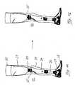
- FIG. 11shows a known prosthetic leg 30 with a receiving stool 31 for a thigh stump.
- a skin friendly Liner 32used, which establishes a symptom-free contact with the thigh stump.
- a rotary adapteris connected via a conventional Justierpyramide.
- the connection of the rotary adapter 33 with a lower leg part 34also takes place via a Justierpyramide.
- the lower leg part 34is designed as a computer-controlled prosthesis part, as it is known under the name "C-Leg” of Otto Bock HealthCare GmbH.
- the lower leg part 34contains a polycentric knee joint 35, which is designed as a four-bar chain in a known form.
- a module tube 36which establishes a connection to an artificial jointless foot 37, the possible structure is also known and need not be explained here.
- Both the artificial foot 37 and the leg prosthesisare provided with a cosmetic coating 38, 39.
- the main function of the prosthesis 30is to allow as natural a gait as possible and a secure standing and comfortable sitting for the individual user of the prosthesis 30.
- the rotary adapter 33is locked during the main function of the prosthesis 30 and can be unlocked when the lower leg part 34th no burden is exercised. By means of the rotary adapter 33, the lower leg of the prosthesis 30 can be rotated relative to the thigh, in particular if the user of the prosthesis 30 is seated.
- the rotary adapter 33can be replaced by the here designated 33 'sensor arrangement, as shown in the FIGS. 1 to 10 has been explained.
- the rotary adapter 33 against the sensor assembly 33Remains the basic function of the prosthesis 30 unchanged when the installation dimensions of the sensor assembly 33 'correspond to those of the rotary adapter 33. It only eliminates the additional function of twisting the lower leg relative to the thigh, which, however, the main function of the prosthesis 30, namely the behavior when walking, standing and sitting is not affected.
- the data required for evaluating the function of the prosthesis 33can be determined on the prosthesis 30, which is individually adapted to the patient and fully functional.
- the sensor arrangement 33 'is useful for the first adaptation of the prosthesis, ie for a short-term use, as well as for a long-term examination of the movement of the patient with the prosthesis 30 specially adapted and adjusted for him.
Landscapes
- Health & Medical Sciences (AREA)
- Life Sciences & Earth Sciences (AREA)
- General Health & Medical Sciences (AREA)
- Transplantation (AREA)
- Engineering & Computer Science (AREA)
- Biomedical Technology (AREA)
- Heart & Thoracic Surgery (AREA)
- Vascular Medicine (AREA)
- Cardiology (AREA)
- Oral & Maxillofacial Surgery (AREA)
- Public Health (AREA)
- Animal Behavior & Ethology (AREA)
- Veterinary Medicine (AREA)
- Prostheses (AREA)
- Measurement Of The Respiration, Hearing Ability, Form, And Blood Characteristics Of Living Organisms (AREA)
- Sampling And Sample Adjustment (AREA)
- Investigating Or Analyzing Materials By The Use Of Electric Means (AREA)
- Investigating Or Analyzing Non-Biological Materials By The Use Of Chemical Means (AREA)
Abstract
Description
Translated fromGermanDie Erfindung betrifft ein Verfahren zur Durchführung einer Funktionsanalyse an einer mit einer künstlichen Extremität ausgerüsteten Person, wobei die künstliche Extremität in in einer Grundfunktion einstellbar und modular mit wenigstens einem ausbaubaren Funktionsteil zur Ermöglichung einer Zusatzfunktion ausgebildet ist. Ein solches Verfahren ist z.B. aus dem Dokument
Künstliche Extremitäten sind in sehr hoch entwickelten Ausführungsformen im Einsatz. Für die unter Sicherheitsaspekten des Patienten besonders relevanten Prothesen für untere Extremitäten unter Einschluss eines künstlichen Kniegelenks werden beispielsweise für die Funktionen "Gehen" und "Stehen" ausgefeilte Technologien eingesetzt, die einerseits ein sicheres Stehen und andererseits einen dem natürlichen Gehen möglichst gut angepassten Bewegungsablauf beim Gehen ermöglichen. Hierzu ist es beispielsweise erforderlich, unter Berücksichtigung der üblichen Auslösekraft des Patienten, beispielsweise über die Bewegung des Oberschenkelstumpfes, ein vollständiges Vorholen des Unterschenkels zu ermöglichen und dabei jedoch ein heftiges Anschlagen des Unterschenkelteils an einen die Streckbewegung begrenzenden Anschlag zu vermeiden. Ersichtlich werden dabei ggf. progressive Dämpfungen eingesetzt, die die gewünschte Funktion jedoch nur gewährleisten, wenn sie in ihrer Dämpfungsdosierung für den jeweiligen Patienten richtig eingestellt sind. Ähnliches gilt für die Auslösung der Gehbewegung aus dem Stehen heraus und für den Übergang vom Gehen zum sicheren Stehen.Artificial extremities are used in very sophisticated embodiments. For the lower limb prostheses, which are particularly relevant for the safety of the patient, including an artificial knee joint, sophisticated technologies are used, for example, for the functions "walking" and "standing", on the one hand a safe standing and on the other hand a walking movement that is as well adapted to natural walking as possible enable. For this purpose, it is necessary, for example, taking into account the usual release force of the patient, for example, on the movement of the femoral stump, to allow a complete prefetching of the lower leg and thereby avoid a violent abutment of the lower leg part of the stretching movement limiting stop. Obviously, if necessary, progressive dampers are used which, however, only ensure the desired function if they are correctly set in their damping dosage for the respective patient. The same applies to the triggering of the walking movement from standing and for the transition from walking to a safe standing.
Es ist bereits bekannt, die Funktion einer derartigen Prothese durch Sensoren zu steuern, die den Übergang von einer Phase der Gehbewegung in eine andere Phase oder den Übergang von der Gehbewegung in eine Stehbewegung und umgekehrt aufgrund von gemessenen Kräften, Beschleunigungen, Momenten o. dgl. ermitteln und Einstellungen der Prothese für die nächste Funktionsphase durchführen. Ein Beispiel für eine derartige Prothese ist die unter der Bezeichnung C-Leg der Anmelderin entwickelte und vertriebene Beinprothese. Auch eine derartige, hoch entwickelte Prothese benötigt jedoch Einstellungsvorgänge, um die Anpassung der Funktion der Prothese an den jeweiligen Patienten zu optimieren. Derartige Einstellungen können unter Berücksichtigung der subjektiven Eindrücke des Patienten bei der Benutzung der Prothese vorgenommen werden. Nachteilig hieran ist jedoch, dass die subjektiven Eindrücke des Patienten schwanken und dass eine Quantifizierung der Eindrücke kaum möglich ist. Die Optimierung der Einstellung der Prothese muss daher nach dem Versuch- und Irrtum-Prinzip erfolgen, um sich so einer optimierten Einstellung anzunähern.It is already known to control the function of such a prosthesis by sensors, the transition from one phase of the walking movement in another phase or the transition from the walking movement in one Standing movement and vice versa due to measured forces, accelerations, moments o. The like. Determine and perform settings of the prosthesis for the next phase of operation. An example of such a prosthesis is the leg prosthesis developed and marketed under the name C-Leg of the Applicant. However, such a sophisticated prosthesis also requires adjustment procedures to optimize the adaptation of the function of the prosthesis to the particular patient. Such adjustments may be made taking into account the subjective impressions of the patient when using the prosthesis. The disadvantage here, however, is that the subjective impressions of the patient fluctuate and that a quantification of the impressions is hardly possible. The optimization of the setting of the prosthesis must therefore be carried out according to the trial and error principle in order to approximate an optimized setting.
Es sind Vorrichtungen bekannt, die eine Stand- und Ganganalyse des mit der Prothese versorgten Patienten in objektivierter Form ermöglichen. Hierfür sind aufwändige und daher teure Messsysteme erforderlich, die nur in wenigen Labors, beispielsweise in Rehabilitationszentren, vorgehalten werden können. Für die Standardanpassung einer Prothese durch den Orthopädiemechaniker sind derartige Messsysteme unerschwinglich, sodass die Standardanpassung ohne Zuhilfenahme derartiger Messsysteme, also im Wesentlichen auf der Basis der subjektiven Eindrücke des Patienten, erfolgt.Devices are known which enable a stand and gait analysis of the patient treated with the prosthesis in objectified form. This requires complex and therefore expensive measuring systems, which can only be kept in a few laboratories, for example in rehabilitation centers. For the standard adaptation of a prosthesis by the orthopedic mechanic, such measuring systems are prohibitively expensive, so that the standard adaptation takes place without the aid of such measuring systems, ie essentially on the basis of the subjective impressions of the patient.
Der vorliegenden Erfindung liegt die Aufgabe zugrunde, eine Funktionsanalyse einer künstlichen Extremität ohne aufwändige Messapparaturen zu ermöglichen.The object of the present invention is to enable a functional analysis of an artificial limb without complex measuring apparatuses.
Zur Lösung dieser Aufgabe ist erfindungsgemäß ein Verfahren der eingangs erwähnten Art dadurch gekennzeichnet, dass anstelle des ausbaubaren Funktionsteils eine an die für den Einbau des Funktionsteils relevanten Abmessungen angepasste Sensoranordnung eingebaut wird, dass mit der Sensoranordnung Kräfte, Beschleunigungen und/oder Momente während der Benutzung der künstlichen Extremität gemessen und zur Optimierung der Einstellung der Grundfunktion der künstlichen Extremität verwendet werden und dass die Sensoranordnung durch das Funktionsteil unter Beibehaltung der optimierten Einstellung ersetzt wird.To solve this problem, a method of the type mentioned is characterized in that instead of the removable functional part of a relevant to the installation of the functional part Dimensions adapted sensor assembly is installed, that measured with the sensor array forces, accelerations and / or moments during use of the artificial limb and used to optimize the adjustment of the basic function of the artificial limb and that the sensor assembly is replaced by the functional part while maintaining the optimized setting ,
Die vorliegende Erfindung ermöglicht somit eine Durchführung von Messungen an der vollständig funktionsfähigen Prothese, die für die Benutzung durch den Patienten vorgesehen und an den Patienten angepasst ist. Die Prothese kann daher über eine beliebig lange Zeit von dem Patienten mit der eingebauten Sensoranordnung benutzt werden, um durch Auswertung der Messwerte feststellen zu können, ob die Einstellung der Prothese noch optimierbar ist und ob beispielsweise bei einer längeren Benutzung der Prothese Änderungen des Gangverhaltens des Patienten eintreten und daher andere Einstellungen der Prothese zweckmäßig wären.The present invention thus enables measurements to be made on the fully functional prosthesis intended for use by the patient and adapted to the patient. The prosthesis can therefore be used for an arbitrarily long time by the patient with the built-in sensor arrangement in order to be able to determine by evaluation of the measured values whether the setting of the prosthesis can still be optimized and if, for example, a prolonged use of the prosthesis changes the gait behavior of the patient occur and therefore other settings of the prosthesis would be appropriate.
Hierin liegt der wesentliche Unterschied zu speziellen Messprothesen, die üblicherweise verwendet werden, um erste Messwerte für einen Patienten zur Erstellung einer angemessenen Prothese zu erhalten. Eine derartige Messprothese ist nicht an den Patienten individuell angepasst und kann daher nur zum Erhalt erster Anhaltspunkte für den speziellen Patienten dienen. Demgegenüber wird erfindungsgemäß die für den Patienten erstellte und vollständig angepasste Prothese in voller Funktionsfähigkeit bezüglich der Grundfunktion der Prothese verwendet.This is the essential difference to specialized prostheses, which are commonly used to obtain initial measurements for a patient to make an appropriate prosthesis. Such a measurement prosthesis is not individually adapted to the patient and therefore can only serve to obtain first clues for the particular patient. In contrast, according to the invention, the prosthesis created for the patient and completely adapted in full functionality with respect to the basic function of the prosthesis is used.
Durch eine kompakt aufgebaute und zuverlässige Daten ermittelnde Sensoranordnung ist es im Rahmen der Erfindung möglich, ein für eine Zusatzfunktion vorgesehenes Funktionsteil der Prothese auszubauen und durch die in ihren Einbauabmessungen angepasste Sensoranordnung zu ersetzen. Selbstverständlich muss die Sensoranordnung dabei so ausgebildet sein, dass sie die Messungen ohne für den Gebrauch merkliche Relativbewegungen auskommt. Bevorzugt ist daher die Ausbildung der Sensoranordnung mit Dehnungsmessstreifen, Piezoelementen o. ä., bei denen Relativbewegungen bzw. Verformungen im Bereich von Bruchteilen eines Millimeters für die Generierung der Messsignale ausreichen.By means of a compactly constructed and reliable data-determining sensor arrangement, it is possible within the scope of the invention to expand a functional part of the prosthesis provided for an additional function and to replace it with the sensor arrangement adapted in its installation dimensions. Of course, the sensor arrangement has to be designed in this way be that she gets the measurements without appreciable relative movements for the use. Preference is therefore given to the design of the sensor arrangement with strain gauges, piezoelectric elements o. Ä., In which relative movements or deformations in the range of fractions of a millimeter sufficient for the generation of the measurement signals.
Ein Beispiel für ein ausbaubares Funktionsteil an einer Beinprothese ist ein Drehadapter, der unmittelbar oberhalb des Kniegelenks eingesetzt wird, um insbesondere im Sitzen eine Drehung des Unterschenkels relative zum Oberschenkel zu ermöglichen, wodurch beispielsweise eine Sitzhaltung mit überschlagenden Beinen erleichtert wird. Für die Durchführung der Funktionsanalyse kann der Patient auf diese Zusatzfunktion, die die Grundfunktion der Beinprothese, nämlich während des Gehvorganges und während des Stehzustandes, nicht beeinflusst, bequem verzichten. Selbstverständlich ist es aber auch möglich, bei einer modular aufgebauten Prothese ein das Unterschenkelteil und das Oberschenkelteil bildende Rohrstück um genau das Maß zu verkürzen, das für den Einbau der Sensoranordnung benötigt wird. Bei einem Ausbau der Sensoranordnung kann dann an das verkürzte Rohrstück ein entsprechendes Verlängerungsstück arigeflanscht oder das verkürzte Rohrstück durch ein längeres Rohrstück ersetzt werden,An example of a removable functional part on a leg prosthesis is a rotary adapter which is inserted immediately above the knee joint, in particular to allow a rotation of the lower leg relative to the thigh, particularly when seated, thereby facilitating, for example, a sitting posture with overturning legs. To carry out the functional analysis, the patient can comfortably dispense with this additional function, which does not affect the basic function of the leg prosthesis, namely during the walking process and during the standing state. Of course, it is also possible to shorten in a modular prosthesis, a lower leg and the thigh part forming tube piece to exactly the extent that is needed for the installation of the sensor assembly. With an expansion of the sensor assembly, a corresponding extension piece can then be arigeflashed on the shortened pipe section or the shortened pipe section can be replaced by a longer pipe section,
Das durch die Sensoranordnung ersetzte Funktionsteil kann auch ein tragendes Modulteil, wie z. B. ein Rohrmodul sein. Das ersetzte Modulteil ist nicht bestimmend für die Grundfunktion, wie dies beispielsweise ein Kniegelenk oder die den Abrollvorgang bestimmenden Teil eines künstlichen Fußes wären. Die Sensoranordnung kann somit auch in Kombination mit einem Rest-Modulteil ausgebildet sein, wobei Gewicht und Gewichtsverteilung dem ersetzten Modulteil im Wesentlichen entsprechen sollten. Ein Beispiel für eine derartige Sensoranordnung ist ein Messsensor mit einem Rest-Unterschenkelrohr, wodurch ein komplettes Unterschenkelrohr einer Beinprothese ersetzt wird.The replaced by the sensor assembly functional part can also be a supporting module part, such. B. be a pipe module. The replaced module part is not decisive for the basic function, as would be, for example, a knee joint or the part of an artificial foot that determines the rolling process. The sensor arrangement can thus also be formed in combination with a remainder module part, wherein weight and weight distribution should substantially correspond to the replaced module part. An example of such a sensor arrangement is a measuring sensor with a residual lower leg tube, whereby a complete lower leg tube of a leg prosthesis is replaced.
Obwohl in der obigen Beschreibung in erster Linie auf eine Prothese für eine untere Extremität eingegangen worden ist, ist es ohne weiteres ersichtlich, dass die Erfindung auch für den Einsatz von Prothesen für die oberen Extremitäten, also Armprothesen, Handprothesen und Schulterprothesen mit Vorteil einsetzbar ist.Although in the above description primarily a prosthesis for a lower limb has been dealt with, it is readily apparent that the invention can also be advantageously used for the use of prostheses for the upper extremities, ie, arm prostheses, hand prostheses and shoulder prostheses.
In allen Fällen können durch die Sensoranordnung selbst oder auch durch zusätzlich in die Prothese eingesetzte Sensoren zusätzliche Messdaten gewonnen werden, wie beispielsweise Drehraten, Winkellagen und Winkeländerungen usw.In all cases, additional measurement data can be obtained by the sensor arrangement itself or by additionally used in the prosthesis sensors, such as rotation rates, angular positions and angle changes, etc.
Die Erfindung soll im Folgenden anhand eines in der Zeichnung dargestellten Ausführungsbeispiels und der Beschreibung einer für die Durchführung der Erfindung besonders geeigneten Sensoranordnung näher erläutert werden. Es zeigen:
Figur 1- eine perspektivische Seitenansicht auf ein erstes Teil einer Sensoranordnung;
Figur 2- eine perspektivische Ansicht von schräg unten auf das erste Teil gemäß
Figur 1 - Figur 3
- eine perspektivische Seitenansicht des zweiten Teils einer Sensoranordnung;
Figur 4- eine perspektivische Ansicht von schräg unten des zweiten Teils gemäß
Figur 3 ; Figur 5- eine perspektivische Seitenansicht der aus den beiden Tei- len zusammengesetzten Sensoranordnung;
Figur 6- eine perspektivische Ansicht von schräg unten der Sensor- anordnung gemäß
Figur 5 Figur 7- eine schematische Schnittdarstellung der Sensoranordnung für eine axiale Belastung (z-Richtung) mit einer schemati- schen Darstellung linienförmiger Stauchbereiche auf dem zweiten Flansch;
Figur 8- eine Darstellung gemäß
Figur 7 - Figur 9
- eine schematische Darstellung gemäß
Figur 7 Figur 10- eine schematische Darstellung gemäß
Figur 7 Figur 11- eine Seitenansicht einer Beinprothese mit einem Drehadap- ter;
Figur 12- eine Seitenansicht gemäß
Figur 11Figuren 1 bis 10
- FIG. 1
- a side perspective view of a first part of a sensor assembly;
- FIG. 2
- a perspective view obliquely from below the first part according to
FIG. 1 ; - FIG. 3
- a side perspective view of the second part of a sensor arrangement;
- FIG. 4
- a perspective view obliquely from below of the second part according to
FIG. 3 ; - FIG. 5
- a side perspective view of the composite of the two parts sensor assembly;
- FIG. 6
- a perspective view obliquely from below the sensor arrangement according to
FIG. 5 ; - FIG. 7
- a schematic sectional view of the sensor arrangement for an axial load (z-direction) with a schematic representation of line-shaped compression areas on the second flange;
- FIG. 8
- a representation according to
FIG. 7 for a torque about a horizontal axis (x-axis); - FIG. 9
- a schematic representation according to
FIG. 7 for an effective lateral force; - FIG. 10
- a schematic representation according to
FIG. 7 for a torque about a vertical axis (z-axis); - FIG. 11
- a side view of a prosthetic leg with a Drehadap- ter;
- FIG. 12
- a side view according to
FIG. 11 in which the rotary adapter by the sensor arrangement according to theFIGS. 1 to 10 has been replaced.
Die
Der hutförmige Anschluss 2 ist mit einer zylindrischen Mantelwandung 5 aufgebaut, in der sich, jeweils um einen Drehwinkel von 90° versetzt, Gewindebohrungen 6 befinden. Der hutförmige Anschluss 2 weist an seiner Oberseite einen kreiszylindrischen Boden 7 und an seiner Unterseite eine kreisringförmige Krempe 8 auf, die einstückig mit dem rechteckigen Flansch 3 verbunden ist und diesen verstärkt.The hat-shaped
Ein derartiger Justieradapter 10 ist an einem zweiten Teil 11 der Sensoranordnung ausgebildet. Das zweite Teil 11 weist einen zweiten, quadratischen Flansch 12 auf, dessen Abmessungen den Abmessungen des ersten Flansches 3 entsprechen. Die beiden Flansche 3, 12 werden durch am zweiten Teil einstückig angeformte Stege 13 miteinander verbunden, die sich an den Ecken des zweiten Flansches 12 nach unten erstrecken, sodass die Stege radial außen von dem hutförmigen Anschluss 2 auf dem ersten Flansch 3 aufliegen. Die Stege 13 sind jeweils mit einer Gewinde-Sackbohrung von ihrer Unterseite aus versehen, die mit den Durchgangsbohrungen 4 des ersten Flansches 3 fluchten können.Such an adjusting
Die
Der Justieradapter 10 befindet sich auf der von den Stegen 13 abgewandten Oberseite 17 des zweiten Flansches 12. Er ist in an sich bekannter Weise in Form eines umgekehrten Pyramidenstumpfes ausgebildet und weist somit vier schräg verlaufende plane Justierflächen 18 auf, die zum Zwecke der Justierung mit Justierschrauben zusammenwirken können. Der Justieradapter 10 geht in einen Sockel 19 mit vergrößertem Durchmesser über, der mit einer gewölbten Fläche einen Übergang zu dem quadratischen zweiten Flansch 12 herstellt.The adjusting
Der Justieradapter 10 bildet einen zweiten Anschluss der Sensoranordnung. Zwischen diesem zweite Anschluss 10 und den in den Ecken des zweiten Flansches 12 angeordneten Stegen 13 befindet sich, somit in Diagonalrichtung des zweiten quadratischen Flansches 12, jeweils eine Ausnehmung 20 in Form einer Durchgangsbohrung, durch die die unten näher beschriebene Ausbildung von Spannungs- bzw. Dehnungsbereichen beeinflussbar ist.The
Die
Die
Die in den
Gemäß
Bei einem in
Anhand der dargestellten Beispiele ist erkennbar, dass mit den Dehnungsmessstreifen 21 als Sensorelemente die verschiedenen auftretenden Kräfte und Momente eindeutig detektierbar sind.It can be seen from the examples shown that the various occurring forces and moments can be clearly detected with the strain gauges 21 as sensor elements.
Die Dehnungsmessstreifen 21 an der Unterseite des zweiten Flansches 12 ergeben jeweils Signale, die komplementär zu den Signalen der Dehnungsmessstreifen 21 an der Oberseite 17 des zweiten Flansches 12 sind, sodass sie bei einer geeigneten Addition zu einem verstärkten Messsignal beitragen können:The strain gauges 21 on the underside of the
An das untere Ende des Aufnahmetrichters 31 ist ein Drehadapter über eine übliche Justierpyramide angeschlossen. Die Verbindung des Drehadapters 33 mit einem Unterschenkelteil 34 erfolgt ebenfalls über eine Justierpyramide.At the lower end of the receiving
Das Unterschenkelteil 34 ist als computergesteuertes Prothesenteil ausgebildet, wie es unter der Bezeichnung "C-Leg" der Otto Bock HealthCare GmbH bekannt ist. Das Unterschenkelteil 34 enthält ein polyzentrisches Kniegelenk 35, das als Viergelenkkette in bekannter Form ausgebildet ist. An das Unterschenkelteil 34 schließt sich nach unten ein Modulrohr 36 an, das eine Verbindung zu einem künstlichen gelenklosen Fuß 37 herstellt, dessen möglicher Aufbau ebenfalls bekannt ist und hier nicht näher erläutert werden muss. Sowohl der künstliche Fuß 37 als auch die Beinprothese sind mit einem kosmetischen Überzug 38, 39 versehen.The
Die Hauptfunktion der Prothese 30 besteht in der Ermöglichung eines möglichst natürlichen Gangverhaltens und eines sicheren Stehens sowie eines bequemen Hinsetzens für den individuellen Nutzer der Prothese 30. Der Drehadapter 33 ist während der Hauptfunktion der Prothese 30 verriegelt und kann entriegelt werden, wenn auf das Unterschenkelteil 34 keine Belastung ausgeübt wird. Durch den Drehadapter 33 kann der Unterschenkel der Prothese 30 gegenüber dem Oberschenkel verdreht werden, insbesondere wenn der Nutzer der Prothese 30 sitzt.The main function of the
Für das Anpassen der Prothese 30 und ggf. in einem späteren Stadium für die Überprüfung der Prothese 30 kann der Drehadapter 33 durch die hier mit 33' bezeichnete Sensoranordnung ersetzt werden, wie sie in den
Claims (3)
- A method for carrying out a functional analysis on a person equipped with an artificial extremity (30), the artificial extremity (30) in a basic function being adjustable, and said artificial extremity (30) being formed in a modular fashion with at least one removable functional part (33), in particular to permit an additional function,characterized in that a sensor assembly (33'), which is adapted to the dimensions relevant for the installation of the functional part, is installed in place of the removable functional part (33),in that forces, accelerations and/or torques are measured by means of the sensor assembly (33') during the use of the artificial extremity (30) and are used to optimize the setting of the basic function of the artificial extremity, andin that the sensor assembly (33') is replaced by the functional part (33) while retaining the optimized setting.
- The method as claimed in claim 1,characterized in that a leg prosthesis is used as artificial extremity (30).
- The method as claimed in claim 2,characterized in that the sensor assembly (33') is adapted to the dimensions of a rotational adaptor (33) arranged above an artificial knee joint.
Applications Claiming Priority (2)
| Application Number | Priority Date | Filing Date | Title |
|---|---|---|---|
| DE102005051496ADE102005051496A1 (en) | 2005-10-26 | 2005-10-26 | Method for performing a functional analysis on an artificial limb |
| PCT/DE2006/001767WO2007048374A1 (en) | 2005-10-26 | 2006-10-10 | Method for carrying out a functional analysis of an artificial extremity |
Publications (2)
| Publication Number | Publication Date |
|---|---|
| EP1940325A1 EP1940325A1 (en) | 2008-07-09 |
| EP1940325B1true EP1940325B1 (en) | 2010-07-21 |
Family
ID=37697949
Family Applications (1)
| Application Number | Title | Priority Date | Filing Date |
|---|---|---|---|
| EP06805385AActiveEP1940325B1 (en) | 2005-10-26 | 2006-10-10 | Method for carrying out a functional analysis of an artificial extremity |
Country Status (11)
| Country | Link |
|---|---|
| US (1) | US8251928B2 (en) |
| EP (1) | EP1940325B1 (en) |
| JP (2) | JP4885970B2 (en) |
| CN (1) | CN101296673B (en) |
| AT (1) | ATE474529T1 (en) |
| BR (1) | BRPI0617743A2 (en) |
| CA (1) | CA2627005C (en) |
| DE (2) | DE102005051496A1 (en) |
| RU (1) | RU2402995C2 (en) |
| TW (1) | TW200716069A (en) |
| WO (1) | WO2007048374A1 (en) |
Families Citing this family (18)
| Publication number | Priority date | Publication date | Assignee | Title |
|---|---|---|---|---|
| WO2008033852A2 (en)* | 2006-09-11 | 2008-03-20 | Orthocare Innovations Llc | Prosthesis, especially lower-limb prosthesis with alignment system using force and moment transducer |
| US10842653B2 (en) | 2007-09-19 | 2020-11-24 | Ability Dynamics, Llc | Vacuum system for a prosthetic foot |
| DE102008024746A1 (en)* | 2008-05-20 | 2009-12-03 | Otto Bock Healthcare Gmbh | Orthopedic device |
| US8409297B2 (en) | 2008-07-11 | 2013-04-02 | Orthocare Innovations Llc | Robotic prosthesis alignment device and alignment surrogate device |
| US20140005801A1 (en)* | 2012-06-27 | 2014-01-02 | Ossur Hf | Alignment adapter for prosthetic sport feet |
| US9833340B2 (en) | 2012-08-30 | 2017-12-05 | Nabtesco Corporation | Detection device of load and moment, and artificial limb including the detection device |
| JP2016516489A (en)* | 2013-03-15 | 2016-06-09 | ウィリアム エル ハンター | Apparatus, system and method for monitoring hip replacements |
| CN103239307B (en)* | 2013-04-24 | 2015-03-25 | 西南交通大学 | Method for detecting load bearing efficiency for power-assisted exoskeletons |
| CN113274173A (en) | 2013-06-23 | 2021-08-20 | 卡纳里医疗公司 | Devices, systems, and methods for monitoring knee replacements |
| US10531968B2 (en) | 2014-05-23 | 2020-01-14 | Joseph Coggins | Prosthetic limb test apparatus and method |
| CA2998709A1 (en) | 2014-09-17 | 2016-03-24 | Canary Medical Inc. | Devices, systems and methods for using and monitoring medical devices |
| KR102854603B1 (en) | 2016-03-23 | 2025-09-04 | 카나리 메디칼 아이엔씨. | Implantable reporting processor for an alert implant |
| EP3821220B1 (en)* | 2018-08-22 | 2024-11-13 | University of Utah Research Foundation | Force and torque sensor for prosthetic and orthopedic devices |
| US10653307B2 (en) | 2018-10-10 | 2020-05-19 | Wm & Dg, Inc. | Medical devices for airway management and methods of placement |
| US12232985B2 (en) | 2019-06-06 | 2025-02-25 | Canary Medical Inc. | Intelligent joint prosthesis |
| US20210366610A1 (en) | 2019-06-06 | 2021-11-25 | Canary Medical Inc. | Intelligent joint prosthesis |
| WO2021188947A1 (en) | 2020-03-20 | 2021-09-23 | University Of Utah Research Foundation | Self-aligning mechanisms in passive and powered exoskeletons |
| US11497394B2 (en) | 2020-10-12 | 2022-11-15 | Wm & Dg, Inc. | Laryngoscope and intubation methods |
Family Cites Families (39)
| Publication number | Priority date | Publication date | Assignee | Title |
|---|---|---|---|---|
| GB2149309B (en)* | 1982-03-02 | 1985-11-20 | Blatchford & Sons Ltd | Making artificial limbs |
| US4911023A (en)* | 1986-07-15 | 1990-03-27 | Ricoh Company, Ltd. | Force sensing apparatus |
| AT393954B (en)* | 1990-02-28 | 1992-01-10 | Bock Orthopaed Ind | METHOD AND DEVICE FOR DETERMINING THE USE PROPERTIES OF A PROSTHETIC PROPERTY |
| US5383939A (en)* | 1991-12-05 | 1995-01-24 | James; Kelvin B. | System for controlling artificial knee joint action in an above knee prosthesis |
| US5413611A (en)* | 1992-07-21 | 1995-05-09 | Mcp Services, Inc. | Computerized electronic prosthesis apparatus and method |
| GB2280609B (en)* | 1993-06-11 | 1997-10-08 | Blatchford & Sons Ltd | Prosthesis control system |
| RU2039538C1 (en)* | 1993-08-24 | 1995-07-20 | Владимир Модестович Брусникин | Device for selecting characteristics of lower extremity prosthesis |
| RU2063195C1 (en)* | 1994-04-17 | 1996-07-10 | Владимир Модестович Брусникин | Method of selection of parameters of lower extremity prosthesis |
| DE9408556U1 (en)* | 1994-05-25 | 1994-07-21 | Biedermann Motech GmbH, 78054 Villingen-Schwenningen | Test prosthesis |
| US5733292A (en)* | 1995-09-15 | 1998-03-31 | Midwest Orthopaedic Research Foundation | Arthroplasty trial prosthesis alignment devices and associated methods |
| DE19718580A1 (en)* | 1997-05-05 | 1998-11-19 | Biedermann Motech Gmbh | Shaft adapter for connecting a stump socket to a prosthetic socket |
| DE19754690A1 (en)* | 1997-12-10 | 1999-07-01 | Biedermann Motech Gmbh | Leg prosthesis with an artificial knee joint with a control device |
| DE19859931A1 (en)* | 1998-12-24 | 2000-07-06 | Biedermann Motech Gmbh | Prosthesis with an artificial knee joint and method for controlling a prosthetic leg |
| GB9921026D0 (en)* | 1999-09-06 | 1999-11-10 | Blatchford & Sons Ltd | A lower limb prosthesis |
| FI110159B (en)* | 1999-12-17 | 2002-12-13 | Respecta Oy | Lower extremity prosthesis |
| DE10000781A1 (en)* | 2000-01-11 | 2001-11-29 | Biedermann Motech Gmbh | Device and method for remote maintenance of an electronically controllable prosthesis |
| US6500138B1 (en)* | 2000-04-07 | 2002-12-31 | Mayo Foundation For Medical Education And Research | Electromechanical joint control device with wrap spring clutch |
| US6905519B2 (en)* | 2001-06-15 | 2005-06-14 | Bionix Prosthetic Solutions, Inc. | Method of forming transfemoral sockets and lock adapter therefor |
| DE10139333A1 (en)* | 2001-08-10 | 2003-03-06 | Biedermann Motech Gmbh | Sensor device, in particular for a prosthesis and prosthesis with such a sensor device |
| ATE427699T1 (en)* | 2002-02-07 | 2009-04-15 | Ecole Polytech | BODY MOVEMENT MONITORING DEVICE |
| US7591857B2 (en)* | 2002-09-20 | 2009-09-22 | Prosthetic Design, Inc. | Prosthetic knee-joint assembly including adjustable proximal and/or distal couplings |
| WO2004041132A2 (en) | 2002-11-01 | 2004-05-21 | Otto Bock Healthcare Lp | Pressure/temperature monitoring device for prosthetics |
| EP1625841A4 (en)* | 2003-05-22 | 2009-04-01 | Hokkaido Tech Licensing Office | DEVICE AND METHOD FOR SENSORY SKIN STIMULATION |
| DE102004004678B4 (en)* | 2004-01-29 | 2005-12-29 | Otto Bock Healthcare Gmbh | torque sensor |
| US7338532B2 (en)* | 2004-05-27 | 2008-03-04 | Engineered Silicone Products L.L.C. | Alignment assembly for a prosthesis |
| US7794499B2 (en)* | 2004-06-08 | 2010-09-14 | Theken Disc, L.L.C. | Prosthetic intervertebral spinal disc with integral microprocessor |
| CN100389733C (en)* | 2004-11-29 | 2008-05-28 | 西安理工大学 | Preparation method of spherical inner hole artificial bone with gradient pore structure |
| EP1843724B1 (en)* | 2005-02-02 | 2018-07-25 | Össur hf | Sensing systems and methods for monitoring gait dynamics |
| DE102005031185A1 (en)* | 2005-07-01 | 2007-01-04 | Otto Bock Healthcare Ip Gmbh & Co. Kg | Orthopedic technical aid, in particular prosthesis for a limb |
| US7507215B2 (en)* | 2005-07-08 | 2009-03-24 | Jri Development Group, Llc | Orthotic brace |
| US7485152B2 (en)* | 2005-08-26 | 2009-02-03 | The Ohio Willow Wood Company | Prosthetic leg having electronically controlled prosthetic knee with regenerative braking feature |
| DE102005051495A1 (en)* | 2005-10-26 | 2007-05-03 | Otto Bock Healthcare Ip Gmbh & Co. Kg | Sensor arrangement for the measurement of forces and / or moments and use of the sensor arrangement |
| US7885705B2 (en)* | 2006-02-10 | 2011-02-08 | Murphy Stephen B | System and method for facilitating hip surgery |
| US20070239165A1 (en)* | 2006-03-29 | 2007-10-11 | Farid Amirouche | Device and method of spacer and trial design during joint arthroplasty |
| WO2008033852A2 (en)* | 2006-09-11 | 2008-03-20 | Orthocare Innovations Llc | Prosthesis, especially lower-limb prosthesis with alignment system using force and moment transducer |
| US7769422B2 (en)* | 2006-09-29 | 2010-08-03 | Depuy Products, Inc. | Apparatus and method for monitoring the position of an orthopaedic prosthesis |
| US20080146969A1 (en)* | 2006-12-15 | 2008-06-19 | Kurtz William B | Total joint replacement component positioning as predetermined distance from center of rotation of the joint using pinless navigation |
| US20090005708A1 (en)* | 2007-06-29 | 2009-01-01 | Johanson Norman A | Orthopaedic Implant Load Sensor And Method Of Interpreting The Same |
| US8421479B2 (en)* | 2009-06-30 | 2013-04-16 | Navisense | Pulsed echo propagation device and method for measuring a parameter |
- 2005
- 2005-10-26DEDE102005051496Apatent/DE102005051496A1/ennot_activeWithdrawn
- 2006
- 2006-10-05TWTW095137069Apatent/TW200716069A/enunknown
- 2006-10-10DEDE502006007497Tpatent/DE502006007497D1/enactiveActive
- 2006-10-10USUS12/091,883patent/US8251928B2/ennot_activeExpired - Fee Related
- 2006-10-10BRBRPI0617743-3Apatent/BRPI0617743A2/ennot_activeIP Right Cessation
- 2006-10-10ATAT06805385Tpatent/ATE474529T1/enactive
- 2006-10-10RURU2008120663/14Apatent/RU2402995C2/ennot_activeIP Right Cessation
- 2006-10-10JPJP2008536919Apatent/JP4885970B2/ennot_activeExpired - Fee Related
- 2006-10-10CACA2627005Apatent/CA2627005C/ennot_activeExpired - Fee Related
- 2006-10-10CNCN2006800400046Apatent/CN101296673B/ennot_activeExpired - Fee Related
- 2006-10-10EPEP06805385Apatent/EP1940325B1/enactiveActive
- 2006-10-10WOPCT/DE2006/001767patent/WO2007048374A1/enactiveApplication Filing
- 2011
- 2011-09-12JPJP2011198299Apatent/JP5730725B2/ennot_activeExpired - Fee Related
Also Published As
| Publication number | Publication date |
|---|---|
| RU2008120663A (en) | 2009-12-10 |
| BRPI0617743A2 (en) | 2011-08-02 |
| US20080287834A1 (en) | 2008-11-20 |
| US8251928B2 (en) | 2012-08-28 |
| CN101296673B (en) | 2012-04-25 |
| JP4885970B2 (en) | 2012-02-29 |
| RU2402995C2 (en) | 2010-11-10 |
| DE102005051496A1 (en) | 2007-05-10 |
| WO2007048374A1 (en) | 2007-05-03 |
| DE502006007497D1 (en) | 2010-09-02 |
| CA2627005A1 (en) | 2007-05-03 |
| JP2009513198A (en) | 2009-04-02 |
| ATE474529T1 (en) | 2010-08-15 |
| CN101296673A (en) | 2008-10-29 |
| CA2627005C (en) | 2013-11-26 |
| JP2012050825A (en) | 2012-03-15 |
| EP1940325A1 (en) | 2008-07-09 |
| JP5730725B2 (en) | 2015-06-10 |
| TW200716069A (en) | 2007-05-01 |
Similar Documents
| Publication | Publication Date | Title |
|---|---|---|
| EP1940325B1 (en) | Method for carrying out a functional analysis of an artificial extremity | |
| EP1940326B1 (en) | Sensor assembly for measuring forces and/or torques and use of said assembly | |
| EP1559384B1 (en) | Torque sensor for a prosthesis | |
| EP1898788B1 (en) | Technical orthopaedic auxiliary agent, in particular prosthesis for an extremity | |
| DE102014105387B4 (en) | Elastic orthosis device with force feedback | |
| WO2006015787A2 (en) | Prosthesis, in particular prosthetic foot | |
| EP2276433A2 (en) | Knee orthosis, and method for controlling a knee orthosis | |
| EP1849439B1 (en) | Jointed knee prosthesis | |
| EP3019126A1 (en) | Orthosis joint | |
| EP2316390B1 (en) | Knee joint for a prosthetic | |
| EP3648710B1 (en) | Prosthesis and prosthetic foot adapter | |
| DE102012012173B4 (en) | Device for adjusting a prosthetic leg and method for creating such a device | |
| EP2276429A1 (en) | Connection adapter | |
| WO2020245424A1 (en) | Test stand for a below-knee orthosis, and method for testing a below-knee orthosis by means of such a test stand | |
| DE3347055C2 (en) | Intermediate piece implant for connecting two sections of bone | |
| DE3214773C2 (en) | Hip joint for an artificial leg | |
| WO2022084112A1 (en) | Extremity dummy and method for testing the functioning of an orthosis | |
| DE102017111558B3 (en) | joint prosthesis | |
| DE202007014810U1 (en) | exerciser | |
| EP1852093B1 (en) | Method for determining the insertion height of a prosthesis | |
| EP3267948A1 (en) | Device for connecting prosthesis components to a prosthesis shaft | |
| EP3829495B1 (en) | Fastening device for fastening a prothesis shaft to a prosthetic knee joint, and prosthetic knee joint |
Legal Events
| Date | Code | Title | Description |
|---|---|---|---|
| PUAI | Public reference made under article 153(3) epc to a published international application that has entered the european phase | Free format text:ORIGINAL CODE: 0009012 | |
| 17P | Request for examination filed | Effective date:20080329 | |
| AK | Designated contracting states | Kind code of ref document:A1 Designated state(s):AT BE BG CH CY CZ DE DK EE ES FI FR GB GR HU IE IS IT LI LT LU LV MC NL PL PT RO SE SI SK TR | |
| GRAP | Despatch of communication of intention to grant a patent | Free format text:ORIGINAL CODE: EPIDOSNIGR1 | |
| DAX | Request for extension of the european patent (deleted) | ||
| RAP1 | Party data changed (applicant data changed or rights of an application transferred) | Owner name:OTTO BOCK HEALTHCARE GMBH | |
| GRAS | Grant fee paid | Free format text:ORIGINAL CODE: EPIDOSNIGR3 | |
| GRAA | (expected) grant | Free format text:ORIGINAL CODE: 0009210 | |
| AK | Designated contracting states | Kind code of ref document:B1 Designated state(s):AT BE BG CH CY CZ DE DK EE ES FI FR GB GR HU IE IS IT LI LT LU LV MC NL PL PT RO SE SI SK TR | |
| REG | Reference to a national code | Ref country code:GB Ref legal event code:FG4D Free format text:NOT ENGLISH | |
| REG | Reference to a national code | Ref country code:CH Ref legal event code:EP | |
| REG | Reference to a national code | Ref country code:IE Ref legal event code:FG4D | |
| REF | Corresponds to: | Ref document number:502006007497 Country of ref document:DE Date of ref document:20100902 Kind code of ref document:P | |
| REG | Reference to a national code | Ref country code:SE Ref legal event code:TRGR | |
| REG | Reference to a national code | Ref country code:NL Ref legal event code:T3 | |
| LTIE | Lt: invalidation of european patent or patent extension | Effective date:20100721 | |
| PG25 | Lapsed in a contracting state [announced via postgrant information from national office to epo] | Ref country code:FI Free format text:LAPSE BECAUSE OF FAILURE TO SUBMIT A TRANSLATION OF THE DESCRIPTION OR TO PAY THE FEE WITHIN THE PRESCRIBED TIME-LIMIT Effective date:20100721 Ref country code:LT Free format text:LAPSE BECAUSE OF FAILURE TO SUBMIT A TRANSLATION OF THE DESCRIPTION OR TO PAY THE FEE WITHIN THE PRESCRIBED TIME-LIMIT Effective date:20100721 | |
| REG | Reference to a national code | Ref country code:IE Ref legal event code:FD4D | |
| PG25 | Lapsed in a contracting state [announced via postgrant information from national office to epo] | Ref country code:CY Free format text:LAPSE BECAUSE OF FAILURE TO SUBMIT A TRANSLATION OF THE DESCRIPTION OR TO PAY THE FEE WITHIN THE PRESCRIBED TIME-LIMIT Effective date:20100721 Ref country code:SI Free format text:LAPSE BECAUSE OF FAILURE TO SUBMIT A TRANSLATION OF THE DESCRIPTION OR TO PAY THE FEE WITHIN THE PRESCRIBED TIME-LIMIT Effective date:20100721 Ref country code:PT Free format text:LAPSE BECAUSE OF FAILURE TO SUBMIT A TRANSLATION OF THE DESCRIPTION OR TO PAY THE FEE WITHIN THE PRESCRIBED TIME-LIMIT Effective date:20101122 Ref country code:PL Free format text:LAPSE BECAUSE OF FAILURE TO SUBMIT A TRANSLATION OF THE DESCRIPTION OR TO PAY THE FEE WITHIN THE PRESCRIBED TIME-LIMIT Effective date:20100721 Ref country code:IS Free format text:LAPSE BECAUSE OF FAILURE TO SUBMIT A TRANSLATION OF THE DESCRIPTION OR TO PAY THE FEE WITHIN THE PRESCRIBED TIME-LIMIT Effective date:20101121 Ref country code:BG Free format text:LAPSE BECAUSE OF FAILURE TO SUBMIT A TRANSLATION OF THE DESCRIPTION OR TO PAY THE FEE WITHIN THE PRESCRIBED TIME-LIMIT Effective date:20101021 | |
| PG25 | Lapsed in a contracting state [announced via postgrant information from national office to epo] | Ref country code:LV Free format text:LAPSE BECAUSE OF FAILURE TO SUBMIT A TRANSLATION OF THE DESCRIPTION OR TO PAY THE FEE WITHIN THE PRESCRIBED TIME-LIMIT Effective date:20100721 Ref country code:GR Free format text:LAPSE BECAUSE OF FAILURE TO SUBMIT A TRANSLATION OF THE DESCRIPTION OR TO PAY THE FEE WITHIN THE PRESCRIBED TIME-LIMIT Effective date:20101022 | |
| PG25 | Lapsed in a contracting state [announced via postgrant information from national office to epo] | Ref country code:IE Free format text:LAPSE BECAUSE OF FAILURE TO SUBMIT A TRANSLATION OF THE DESCRIPTION OR TO PAY THE FEE WITHIN THE PRESCRIBED TIME-LIMIT Effective date:20100721 Ref country code:DK Free format text:LAPSE BECAUSE OF FAILURE TO SUBMIT A TRANSLATION OF THE DESCRIPTION OR TO PAY THE FEE WITHIN THE PRESCRIBED TIME-LIMIT Effective date:20100721 | |
| BERE | Be: lapsed | Owner name:OTTO BOCK HEALTHCARE G.M.B.H. Effective date:20101031 | |
| PLBE | No opposition filed within time limit | Free format text:ORIGINAL CODE: 0009261 | |
| STAA | Information on the status of an ep patent application or granted ep patent | Free format text:STATUS: NO OPPOSITION FILED WITHIN TIME LIMIT | |
| PG25 | Lapsed in a contracting state [announced via postgrant information from national office to epo] | Ref country code:MC Free format text:LAPSE BECAUSE OF NON-PAYMENT OF DUE FEES Effective date:20101031 Ref country code:SK Free format text:LAPSE BECAUSE OF FAILURE TO SUBMIT A TRANSLATION OF THE DESCRIPTION OR TO PAY THE FEE WITHIN THE PRESCRIBED TIME-LIMIT Effective date:20100721 Ref country code:CZ Free format text:LAPSE BECAUSE OF FAILURE TO SUBMIT A TRANSLATION OF THE DESCRIPTION OR TO PAY THE FEE WITHIN THE PRESCRIBED TIME-LIMIT Effective date:20100721 Ref country code:EE Free format text:LAPSE BECAUSE OF FAILURE TO SUBMIT A TRANSLATION OF THE DESCRIPTION OR TO PAY THE FEE WITHIN THE PRESCRIBED TIME-LIMIT Effective date:20100721 Ref country code:RO Free format text:LAPSE BECAUSE OF FAILURE TO SUBMIT A TRANSLATION OF THE DESCRIPTION OR TO PAY THE FEE WITHIN THE PRESCRIBED TIME-LIMIT Effective date:20100721 | |
| REG | Reference to a national code | Ref country code:CH Ref legal event code:PL | |
| 26N | No opposition filed | Effective date:20110426 | |
| PG25 | Lapsed in a contracting state [announced via postgrant information from national office to epo] | Ref country code:ES Free format text:LAPSE BECAUSE OF FAILURE TO SUBMIT A TRANSLATION OF THE DESCRIPTION OR TO PAY THE FEE WITHIN THE PRESCRIBED TIME-LIMIT Effective date:20101101 | |
| PG25 | Lapsed in a contracting state [announced via postgrant information from national office to epo] | Ref country code:LI Free format text:LAPSE BECAUSE OF NON-PAYMENT OF DUE FEES Effective date:20101031 Ref country code:CH Free format text:LAPSE BECAUSE OF NON-PAYMENT OF DUE FEES Effective date:20101031 | |
| REG | Reference to a national code | Ref country code:DE Ref legal event code:R097 Ref document number:502006007497 Country of ref document:DE Effective date:20110426 | |
| PG25 | Lapsed in a contracting state [announced via postgrant information from national office to epo] | Ref country code:BE Free format text:LAPSE BECAUSE OF NON-PAYMENT OF DUE FEES Effective date:20101031 | |
| PG25 | Lapsed in a contracting state [announced via postgrant information from national office to epo] | Ref country code:LU Free format text:LAPSE BECAUSE OF NON-PAYMENT OF DUE FEES Effective date:20101010 Ref country code:HU Free format text:LAPSE BECAUSE OF FAILURE TO SUBMIT A TRANSLATION OF THE DESCRIPTION OR TO PAY THE FEE WITHIN THE PRESCRIBED TIME-LIMIT Effective date:20110122 | |
| PG25 | Lapsed in a contracting state [announced via postgrant information from national office to epo] | Ref country code:TR Free format text:LAPSE BECAUSE OF FAILURE TO SUBMIT A TRANSLATION OF THE DESCRIPTION OR TO PAY THE FEE WITHIN THE PRESCRIBED TIME-LIMIT Effective date:20100721 | |
| REG | Reference to a national code | Ref country code:AT Ref legal event code:MM01 Ref document number:474529 Country of ref document:AT Kind code of ref document:T Effective date:20111010 | |
| PG25 | Lapsed in a contracting state [announced via postgrant information from national office to epo] | Ref country code:AT Free format text:LAPSE BECAUSE OF NON-PAYMENT OF DUE FEES Effective date:20111010 | |
| REG | Reference to a national code | Ref country code:DE Ref legal event code:R082 Ref document number:502006007497 Country of ref document:DE Representative=s name:GRAMM, LINS & PARTNER PATENT- UND RECHTSANWAEL, DE | |
| REG | Reference to a national code | Ref country code:FR Ref legal event code:PLFP Year of fee payment:10 | |
| REG | Reference to a national code | Ref country code:FR Ref legal event code:PLFP Year of fee payment:11 | |
| REG | Reference to a national code | Ref country code:FR Ref legal event code:PLFP Year of fee payment:12 | |
| PGFP | Annual fee paid to national office [announced via postgrant information from national office to epo] | Ref country code:SE Payment date:20171024 Year of fee payment:12 Ref country code:IT Payment date:20171020 Year of fee payment:12 Ref country code:NL Payment date:20171023 Year of fee payment:12 | |
| REG | Reference to a national code | Ref country code:DE Ref legal event code:R082 Ref document number:502006007497 Country of ref document:DE Representative=s name:GRAMM, LINS & PARTNER PATENT- UND RECHTSANWAEL, DE Ref country code:DE Ref legal event code:R081 Ref document number:502006007497 Country of ref document:DE Owner name:OTTOBOCK SE & CO. KGAA, DE Free format text:FORMER OWNER: OTTO BOCK HEALTHCARE GMBH, 37115 DUDERSTADT, DE | |
| REG | Reference to a national code | Ref country code:FR Ref legal event code:PLFP Year of fee payment:13 | |
| REG | Reference to a national code | Ref country code:SE Ref legal event code:EUG | |
| REG | Reference to a national code | Ref country code:NL Ref legal event code:MM Effective date:20181101 | |
| PG25 | Lapsed in a contracting state [announced via postgrant information from national office to epo] | Ref country code:SE Free format text:LAPSE BECAUSE OF NON-PAYMENT OF DUE FEES Effective date:20181011 Ref country code:NL Free format text:LAPSE BECAUSE OF NON-PAYMENT OF DUE FEES Effective date:20181101 | |
| PG25 | Lapsed in a contracting state [announced via postgrant information from national office to epo] | Ref country code:IT Free format text:LAPSE BECAUSE OF NON-PAYMENT OF DUE FEES Effective date:20181010 | |
| PGFP | Annual fee paid to national office [announced via postgrant information from national office to epo] | Ref country code:GB Payment date:20231025 Year of fee payment:18 | |
| PGFP | Annual fee paid to national office [announced via postgrant information from national office to epo] | Ref country code:FR Payment date:20231023 Year of fee payment:18 | |
| PGFP | Annual fee paid to national office [announced via postgrant information from national office to epo] | Ref country code:DE Payment date:20241022 Year of fee payment:19 | |
| GBPC | Gb: european patent ceased through non-payment of renewal fee | Effective date:20241010 | |
| PG25 | Lapsed in a contracting state [announced via postgrant information from national office to epo] | Ref country code:GB Free format text:LAPSE BECAUSE OF NON-PAYMENT OF DUE FEES Effective date:20241010 | |
| PG25 | Lapsed in a contracting state [announced via postgrant information from national office to epo] | Ref country code:FR Free format text:LAPSE BECAUSE OF NON-PAYMENT OF DUE FEES Effective date:20241031 |