EP1939619B1 - Apparatus and method for generating nitrogen oxides - Google Patents
Apparatus and method for generating nitrogen oxidesDownload PDFInfo
- Publication number
- EP1939619B1 EP1939619B1EP08250005AEP08250005AEP1939619B1EP 1939619 B1EP1939619 B1EP 1939619B1EP 08250005 AEP08250005 AEP 08250005AEP 08250005 AEP08250005 AEP 08250005AEP 1939619 B1EP1939619 B1EP 1939619B1
- Authority
- EP
- European Patent Office
- Prior art keywords
- combustion
- supply
- analyser
- ozone
- nitrogen
- Prior art date
- Legal status (The legal status is an assumption and is not a legal conclusion. Google has not performed a legal analysis and makes no representation as to the accuracy of the status listed.)
- Not-in-force
Links
Images


Classifications
- C—CHEMISTRY; METALLURGY
- C01—INORGANIC CHEMISTRY
- C01B—NON-METALLIC ELEMENTS; COMPOUNDS THEREOF; METALLOIDS OR COMPOUNDS THEREOF NOT COVERED BY SUBCLASS C01C
- C01B21/00—Nitrogen; Compounds thereof
- C01B21/20—Nitrogen oxides; Oxyacids of nitrogen; Salts thereof
- C01B21/203—Preparation of nitrogen oxides using a plasma or an electric discharge
- G—PHYSICS
- G01—MEASURING; TESTING
- G01N—INVESTIGATING OR ANALYSING MATERIALS BY DETERMINING THEIR CHEMICAL OR PHYSICAL PROPERTIES
- G01N25/00—Investigating or analyzing materials by the use of thermal means
- G01N25/20—Investigating or analyzing materials by the use of thermal means by investigating the development of heat, i.e. calorimetry, e.g. by measuring specific heat, by measuring thermal conductivity
- G01N25/22—Investigating or analyzing materials by the use of thermal means by investigating the development of heat, i.e. calorimetry, e.g. by measuring specific heat, by measuring thermal conductivity on combustion or catalytic oxidation, e.g. of components of gas mixtures
- G01N25/24—Investigating or analyzing materials by the use of thermal means by investigating the development of heat, i.e. calorimetry, e.g. by measuring specific heat, by measuring thermal conductivity on combustion or catalytic oxidation, e.g. of components of gas mixtures using combustion tubes, e.g. for microanalysis
- G—PHYSICS
- G01—MEASURING; TESTING
- G01N—INVESTIGATING OR ANALYSING MATERIALS BY DETERMINING THEIR CHEMICAL OR PHYSICAL PROPERTIES
- G01N31/00—Investigating or analysing non-biological materials by the use of the chemical methods specified in the subgroup; Apparatus specially adapted for such methods
- G01N31/12—Investigating or analysing non-biological materials by the use of the chemical methods specified in the subgroup; Apparatus specially adapted for such methods using combustion
- Y—GENERAL TAGGING OF NEW TECHNOLOGICAL DEVELOPMENTS; GENERAL TAGGING OF CROSS-SECTIONAL TECHNOLOGIES SPANNING OVER SEVERAL SECTIONS OF THE IPC; TECHNICAL SUBJECTS COVERED BY FORMER USPC CROSS-REFERENCE ART COLLECTIONS [XRACs] AND DIGESTS
- Y10—TECHNICAL SUBJECTS COVERED BY FORMER USPC
- Y10T—TECHNICAL SUBJECTS COVERED BY FORMER US CLASSIFICATION
- Y10T436/00—Chemistry: analytical and immunological testing
- Y10T436/17—Nitrogen containing
- Y10T436/176152—Total nitrogen determined
Definitions
- the inventionrelates to an apparatus and method for generating nitrogen oxides in the combustion analysis of samples comprising a proportion of sulphur.
- Combustion analysersare used to determine the concentration of one or more components of a sample, by combusting the sample and analysing the gaseous products for specific oxides.
- the carbon, sulphur and/or nitrogen content of the sampleis measured by detecting CO 2 , SO 2 and NO, respectively.
- the combustion analyser 10comprises a sample introduction stage 20, a combustion stage 30, a conditioning stage 40, and a detection stage 50.
- the sample introduction stage 20comprises a sample introduction apparatus 22, to which are connected a supply of a sample 24, a supply of oxygen 26 and a supply of argon 27.
- the sample introduction apparatus 22introduces these fluids into a combustion chamber 32 in a suitable form for combustion to take place.
- a further supply of oxygen 25may be provided, directly into the combustion chamber 32.
- the combustion chamber 32is heated by an electric heater 34, so that the sample is delivered into an oxygen-rich atmosphere at high temperature, typically of around 1000°C.
- the sampleis thereby converted into various combustion products, such as CO 2 , H 2 O, SO 2 , NO, etc.
- the combustion productsleave the combustion chamber 32 and pass through the conditioning stage 40, where processes such as cooling, filtering, drying, etc. take place.
- the conditioned productsthen pass through one or more dedicated detectors 52, 54, in which properties of the components of the combustion products may be detected.
- CO 2may be detected by absorption of infrared radiation, using a non-dispersive infrared (NDIR) detector
- SO 2may be detected by fluorescence with ultraviolet light, using a light sensor
- NOcan be detected from de-excitation processes following its reaction with ozone (O 3 ) to form excited NO 2 , using a chemiluminescence light sensor.
- the detected signalsare indicative of the respective amount of each component of the combustion products and can therefore be related to the composition of the original sample.
- the detected combustion productsare passed out of the detection stage 50, as waste products 56.
- the combustion product to be detectedis sulphur dioxide (SO 2 ).
- SO 2sulphur dioxide
- the achievable yield of SO 2 which may be detected with current combustion analysersis around 90%.
- the yieldis the proportion of the amount of sulphur originally contained in the sample which is actually converted to sulphur dioxide.
- the achievable yield of a combustion analyseris calculated by analysing known, standard samples for calibration purposes. Once a calibration curve has been measured using standard samples, unknown samples may be analysed and the detected values may be calibrated accordingly. However, samples and also combustion conditions in a combustion analyser are subject to variation, with the result that the calibration curve cannot consistently provide accurate measurements from sample to sample.
- US 4,879,246relates to a device for the mineralization of carbonaceous material by heating a solid sample to 300-400°C for 6-20 hours in a stream of oxygen and ozone/nitrogen oxides/chlorine. Ashes are formed as the resulting mineralization product and these are dissolved for chemical analysis.
- GB 269,046relates generally to an apparatus for ozonising air and converting it into nitric oxide.
- a combustion analyserfor combustion analysing a sample by combusting the sample and analysing the gaseous products
- the analysercomprising: a combustion chamber for receiving a sample for combustion therein to form said gaseous combustion products; a fluid supply apparatus for supplying one or more fluids into the combustion chamber; and a detector for detecting SO 2 in said gaseous combustion products; characterised in that the fluid supply apparatus comprises a nitrogen oxides (NOx) generating apparatus and the fluid supply apparatus is arranged to supply NO x into the combustion chamber.
- NOxnitrogen oxides
- nitrogen monoxideacts as a sulphur dioxide yield improver in the combustion analyser.
- the nitrogen monoxideincreases the yield of sulphur dioxide in the combustion products to be detected, relative to the yield of sulphur dioxide in the combustion products which would result when the substance is not added to the combustion analyser.
- a greater quantity of sulphur dioxidefor a given sample volume or mass, can be produced, offering improved detection.
- the effect of variations between samples and variations in other combustion conditionscan be reduced, if not minimised. This can help to ensure that measurements made using the calibration curve are accurate from sample to sample.
- NO xrefers generally to oxides of nitrogen, which typically include nitrogen monoxide (NO), nitrogen dioxide (NO 2 ), dinitrogen trioxide (N 2 O 3 ) etc., in various proportions.
- NOnitrogen monoxide
- NO 2nitrogen dioxide
- N 2 O 3dinitrogen trioxide
- the NO xis supplied to the combustion analyser before and/or during combustion of the sample.
- the mechanism by which the NO improves the yield of sulphur dioxide in the combustion gasesmay be such that the NO reduces sulphur trioxide to sulphur dioxide, or inhibits the formation of sulphur trioxide, or promotes the formation of sulphur dioxide, or a combination of these. Accordingly, it is preferred that the NO x be supplied before or during combustion of a sample, to allow the NO to have sufficient opportunity to have effect.
- the NO xmay be supplied to the combustion chamber of the combustion analyser via a dedicated inlet.
- the NO x gasesmay be pumped directly into the combustion chamber. Again, such supply may take place before and/or during combustion.
- combustion chambershave one or more inlet ports for receiving a supply of oxygen and a carrier gas, such as argon, respectively.
- a carrier gassuch as argon
- the NO xmay be connected to the supply line for oxygen or a carrier gas, and carried into the combustion chamber therewith.
- the connectionmay be made anywhere along such supply line and is preferably in the form of a two-into-one connector (such as a 'T' piece).
- the connector or the apparatus connecting the NO x to a dedicated inlet, or to an oxygen supply line or a carrier gas supply lineis switchable between an on and an off state, so that during analysis of samples for which the NO yield improver is not required, the supply of the NO x may be stopped.
- a NO x generatorallows for a relatively simple technique for supplying a source of NO into the analyser.
- a NO x generatormay most simply be provided by modifying an ozonator to receive a supply of nitrogen and oxygen, instead of pure oxygen. With the use of a NO x generator, it is not necessary to spike or dilute a liquid sample with a nitrogen-containing compound, which process is labour intensive.
- the NO x producedmay most straightforwardly be supplied into one or other of the gas supply lines. This allows for retrofitting of the NO x generator to existing combustion analysers. It is also not necessary to provide a modified combustion chamber, in this case.
- One particular advantage of the inventionis that it is possible to use air (preferably first conditioned) as the supply of nitrogen and oxygen.
- Air intakes for ozonatorstypically condition the air by removing nitrogen, among other components. However, in embodiments of this invention, the nitrogen is not removed.
- the NO x generatoris operated at a slightly elevated temperature, say between 10 and 30°C above room temperature. This has been found to improve the yield of NO x from the generator.
- Samples for combustion analysismay be petrochemicals, high-grade chemicals, or food and beverage specimens, for which the concentration of sulphur in the sample may be subject to regulation, so that at least an estimated, or expected, proportion of sulphur may be known before combustion analysis. If the proportion of sulphur is entirely unknown, a first quantity of the sample may be analysed, to obtain an indication of the proportion of sulphur, so that an expected proportion of sulphur may be known for subsequent analyses.
- the amount of NO x supplied to the combustion analyseris such that a proportion of NO yield improver in the combustion analyser is greater than the expected proportion of sulphur in a sample.
- the proportion of NO yield improver to the expected proportion of sulphuris greater than 2 to 1.
- the proportionis greater than 4 to 1. It has been found that, with tests using standard samples, adding a greater proportion of NO yield improver than the expected (in the case of a standard sample, the known) proportion of sulphur increases the yield of sulphur dioxide. Above a ratio of NO yield improver to sulphur of about 4 or 5 to 1, it has been found that the yield of sulphur dioxide does not increase so rapidly but starts to level off.
- relative proportions, or ratios, of NO to SO 2is meant molar proportions/ratios, and not proportions/ratios based on volume or mass.
- a proportion of NO yield improver to the expected proportion of sulphur of up to 1000 to 1would be sufficient to ensure that an increased and substantially consistent yield of sulphur dioxide is achieved, even taking into account potentially significant variations in the actual proportion of sulphur in different samples.
- a proportion of NO yield improver to the expected proportion of sulphur of up to 25-50 to 1would be more than sufficient.
- a ratio of 5 to 1may be preferable, for example, where large variations in the sulphur content are not expected between samples.
- the combustion products at the detectormay comprise nitrogen monoxide.
- the inventorshave found that nitrogen monoxide interferes with the detection of sulphur dioxide, when using a UV fluorescence detector. It is therefore preferable to provide an ozone supply to the combustion products, prior to detection, where nitrogen monoxide would otherwise interfere. Ozone reacts with nitrogen monoxide to form nitrogen dioxide and oxygen, so may be used to remove the NO interference.
- the ozoneis preferably added between the combusting step and the detecting step. The ozone may be added after the combustion chamber or to the detector, or to a location in between, such as the transfer tubing between the chamber and detector.
- an ozone supply apparatusmay be fitted to an existing combustion analyser relatively straightforwardly, by adding a connection into the combustion products line between the combustion chamber and the detector.
- the connectoris a two-into-one connector, such as a 'T' piece or the like.
- the ozoneis supplied at a rate of between approximately 0.5 to 1 ml/s.
- the connector or the ozone supply apparatusis switchable between an on and an off state, so that ozone is not supplied when not required.
- the NO x generating apparatus and the ozone supply apparatusare provided together by: an electric discharge generator having a discharge region and arranged to provide an electric discharge through the discharge region; a first, NO x conduit disposed in a first part of the discharge region and comprising a NO x source gas inlet for receiving a supply of NO x source gas into the NO x conduit and a NO x gas outlet for supplying NO x gas therefrom; a second, ozone conduit disposed in a second part of the discharge region and comprising an ozone source gas inlet for receiving a supply of ozone source gas into the ozone conduit and an ozone gas outlet for supplying ozone gas therefrom.
- both NO x and ozonecan be produced using the same electric discharge device. This can provide a saving on components, as only one power supply and transformer is required to provide the electric discharges.
- a Venturi tube with an oxygen flow therethroughis used to draw the generated NO x from the NO x generator into an inlet hole provided in the constriction of the Venturi tube.
- the NO x generating apparatuscomprises: an electric discharge generator having a discharge region and arranged to provide an electric discharge through the discharge region; a NO x conduit disposed in the discharge region and comprising a NO x source gas inlet for receiving a supply of NO x source gas into the NO x conduit and a NO x gas outlet for supplying NO x gas therefrom, wherein the NO x gas outlet comprises a Venturi tube having a tube constriction, an intake opening near the tube constriction, and a Venturi tube outlet downstream of the tube constriction, the Venturi tube being arranged to receive a fluid flow through the tube constriction such that NO x gas is drawn into the intake opening and supplied from the Venturi tube outlet.
- a method of combustion analysing a sample by combusting the sample in a combustion chamber of a combustion analyser and analysing the gaseous productscomprising the steps of: supplying the sample to the combustion chamber; combusting the sample to produce combustion products; and detecting SO 2 in the combustion products, characterised by the step of generating nitrogen oxides (NO x ) and supplying the generated NOx to the combustion 5 chamber.
- NO xnitrogen oxides
- the NO x and ozoneare generated by providing a single electric discharge region; passing a mixture of nitrogen and oxygen through a first part of the region, to generate NO x ; and passing oxygen through a second part of the region, to generate ozone.
- the inventionpreferably uses an ozonator with a nitrogen and oxygen supply to generate NOx to be supplied to a combustion chamber of a combustion analyser for combustion analysing a sample by combusting the sample and analysing the gaseous products.
- the combustion analyser 120has a sample introduction apparatus 72, which includes a sample supply inlet 74, an oxygen supply inlet 75, and a carrier gas supply inlet 77.
- the sample introduction apparatus 72is connected to a combustion chamber 82, which is heated by a heater 84.
- the combustion chamber 82is divided into two compartments, the second of which being a turbo compartment and having a further oxygen supply inlet 76, to promote complete combustion of a sample.
- Combustion products formed in the combustion chamber 82pass through a conditioning stage 90, before detection.
- the conditioning stageincludes a dryer 92, which removes water from the combustion products, the water being entrained by a dry gas flow in the opposite direction to the combustion products, the dry gas flow flowing through an outer tube of the dryer.
- the conditioning stagealso includes a filter 94.
- the conditioned combustion productsthen pass through a combustion product line 96 to a detector 150.
- the combustion analyser 120has an oxygen supply line 130 connected to the oxygen supply inlet 75.
- the oxygen supply linehas an end 132 for connection to an oxygen feed unit (not shown).
- the combustion analyser 120has a carrier gas (typically argon) supply line 134 connected to the carrier gas supply inlet 77.
- the carrier gas supply linehas an end 136 for connection to a carrier gas feed unit (not shown).
- the NO x generator 140is configured to provide a supply of NO x into one, both or none of the oxygen and carrier gas supply lines 130, 134.
- the NO x generator 140is connected to both supply lines 130, 134, by a switchable connector (not shown), which may be switched between various settings, depending on the application: Setting Oxygen supply line Carrier gas supply line A Oxygen Carrier gas B Oxygen & NO x Carrier gas C Oxygen Carrier gas & NO x D Oxygen & NO x Carrier gas & NO x
- a connectormay be fitted only to one of the supply lines 130, 134.
- the NO x generator 140in this embodiment, is configured to supply nitrogen oxide gases into one or both of the supply lines 130, 134.
- a flow of oxygenpasses into end 132 and, from the supply line 130, into the supply inlet 75 and on into the combustion chamber 82.
- a typical flow rate for the oxygenis between 200 and 400 ml/min.
- the NO x gasis pumped into the oxygen supply line 130 through the connector, where it mixes with the oxygen, for supply to the combustion chamber.
- a preferred flow rate for the NO x gasis between 15 and 50 ml/min. Such a flow rate is generally suitable to provide an abundance of NO in the combustion chamber before and/or during the combustion process, so that the yield of SO 2 in the combustion products may be improved.
- the combustion products formed in the combustion chamber 82 - including an improved yield of SO 2 -are carried through the conditioning stage 90 and along the combustion products line 96, by a general, background flow of carrier gas or oxygen through the analyser 120. From the combustion products line 96, the combustion products are passed into one or more detectors 150 (not shown), one of which is configured to detect an amount of SO 2 therein.
- the detector 150 for detecting SO 2can be any suitable detector and is not limited to a UV fluorescence detector.
- the detector 150may be a coulometric detector using iodometric titration.
- the combustion gases containing SO 2are passed through the electrolyte of a titration cell, containing tri-iodide (I 3 - ).
- the sulphur dioxidereacts with the tri-iodide to form a sulphate and iodide. This reaction changes the potential from its preset value of the cell and this is detected.
- iodideis reduced to iodine, to compensate for the tri-iodide deficiency, by an applied current.
- the currentis integrated over time, providing a measurement of the amount titrated sulphur dioxide, from which the amount of sulphur in the sample may be calculated.
- the reaction equations for this processare: 6 ⁇ H 2 ⁇ O + SO 2 + I 3 - ⁇ SO 4 2 - + 3 ⁇ I - + 4 ⁇ H 3 ⁇ 0 + 2 ⁇ I - ⁇ I 2 + 2 ⁇ e - ⁇ at the anode I 2 + I - ⁇ I 3 - ⁇ at the anode 2 ⁇ H 3 ⁇ O + 2 ⁇ e - ⁇ H 2 + 2 ⁇ H 2 ⁇ 0 ⁇ at the cathode
- the inventionimproves the detectable sulphur yield by increasing the yield of SO 2 in the combustion gases, the invention may be applied to any combustion analyser employing a sulphur dioxide detection mechanism and provide corresponding advantages thereto.
- sulphur trioxideSO 3
- TSUVTotal sulphur ultraviolet detection is based on the principle that SO 2 molecules fluoresce; i.e., absorb UV light, become excited, then relax to a lower energy state, emitting UV light at a specific wavelength in the process. The emitted light is detected to provide a measure of the amount of SO 2 present.
- the inventorshave recognised that the readings taken by the above type of detector are not a result purely of SO 2 fluorescence. It has been found that the detector is unable to distinguish between SO 2 and NO, since they both fluoresce upon excitation with UV light in generally the same wavelength range. Accordingly, the inventors have appreciated that measurements made by such a detector may indicate higher levels of SO 2 than are actually present in the fluorescence chamber, since NO fluorescence can contribute to the detected signal. Many samples contain a proportion of nitrogen and so can be incorrectly quantified by the detector.
- TN detectorWhen it is desired to measure the concentration of nitrogen in a sample, it is known to use a total nitrogen (TN) detector, as mentioned above. This is a chemiluminescence detector, which measures the amount of light emitted when excited nitrogen dioxide falls to its ground state. The excited nitrogen dioxide is formed from the reaction of nitrogen monoxide with ozone (O 3 ). The reaction mechanism used in TN detectors has been applied in sulphur dioxide analysis.
- FIG 3shows schematically a combustion analyser 160, which is similar to that shown in figure 2 , but with some modifications.
- a UV fluorescence detector 100At the end of the combustion products line 96, there is provided a UV fluorescence detector 100.
- An ozone generator 170is installed on the combustion products line 96 between the combustion chamber 82 and the detector 100, so that any nitrogen monoxide in the combustion products may react with the ozone and thereby be removed from the combustion products and not be detected by the sulphur dioxide UV fluorescence detector 100.
- An ozonatoralso known as an ozonizer
- the ozone generator 170is configured to supply ozone to the combustion products line 96 at a rate sufficient to remove substantially all of the nitrogen monoxide. For example, an oxygen flow of 50 ml/min supplied to an ozonator has been found to be sufficient to remove the nitrogen monoxide formed from a nitrogen concentration in the combustion products of up to 9000 ppm.
- the ozone mixed into the combustion productsshould preferably be supplied in a greater quantity than is needed to remove all NO gas, to help ensure substantially all NO gas is converted to NO 2 . Since ozone is toxic, it should preferably not simply be pumped to waste. Accordingly, the combustion analyser 160 has a waste discharge line 58, which passes through or near to the combustion chamber heater 84. In this way, ozone present in the waste products from the detector 100 may be thermally dissociated into oxygen before being discharged from the analyser. Other techniques for ozone removal may alternatively be employed.
- a combustion analyser to detect SO 2 by UV fluorescence detectionwas modified to allow it to operate under a number of different conditions.
- the analyser usedwas the SphiNCX analyser, manufactured by Thermo Fisher Scientific Inc..
- the modifications madewere to add a nitrogen oxides (NO x ) generator to the oxygen supply line, by means of a switchable connector, and to add an ozone generator to the combustion products line, again by means of a switchable connector.
- the switchable connectorswere used so that one or both of the supplies could be turned off, as required.
- the following methods of analysiswere used with each of the eight samples, respectively.
- method Athe analysis was conducted with both the NO x and O 3 supplies turned off; that is, essentially, the SphiNCX analyser was operating in its standard manner according to international standard ASTM D5453 for total sulphur determination.
- method Bthe analysis was conducted with the O 3 supply switched on and the NO x supply switched off. That is, the combustion process was as standard, but substantially all NO in the combustion products was removed.
- method Cthe analysis was conducted with both NO x and O 3 supplies turned on. That is, the analysis was as standard, but a yield improver gas was supplied to the combustion chamber, along with the oxygen supply, and substantially all NO in the combustion products was removed.
- the ozone gas flow rate into the combustion products linewas 50 ml/min.
- the NO x generatorwas employed, the NO x flow rate into the oxygen supply line was between 34 and 40 ml/min.
- the sulphur-containing liquid usedwas thiophene.
- the results of the testsare shown in table 1 and on the graph of figure 4 .
- the results for method Agenerally show a rise in the detected concentration of total sulphur in the eight standard samples, with increasing nitrogen in the samples. With no added nitrogen-containing liquid in the sample (sample 1), the yield of SO 2 was around 90%. The apparent yield of SO 2 for sample 8 was around 110%, clearly confirming that the UV fluorescence detector was measuring a signal from an interfering substance (NO), in addition to the SO 2 .
- Table 1Influence of added nitrogen with different methods of determining sulphur on 10 ppm sulphur.
- the results for method Bdo not show an ever-increasing detected concentration of total sulphur, with increasing nitrogen concentration in the samples. Provided sufficient ozone is mixed with the combustion products, substantially all NO can be removed from them. This means that the signal generated by the detector is substantially wholly from the fluorescence of SO 2 and indicates that the actual yield of SO 2 was around 87%. Accordingly, a calibration curve based on standard samples analysed using method B may be obtained and used to provide total sulphur measurements of unknown samples, without interference from NO in the detector.
- the yield of SO 2is not consistent across samples 1 to 8, but varies from around 87% to around 96%, as the nitrogen concentration in the samples varies.
- the yielddoes appear to level off at around 95-96% from nitrogen concentrations in the sample of about 40-50 ppm and, before that, there is a reasonable yield, of over 90%, for nitrogen concentrations above about 10 ppm.
- the yield of SO 2is affected by variations in the concentration of nitrogen in the samples. Since, for actual samples, the concentration of nitrogen is unknown and may vary between samples, a calibration curve obtained under method B would be an improvement on one obtained under method A, but still could not assure consistent applicability.
- the results for method Care similar to those for method B, in that the detected concentration of total sulphur does not continue increasing with increasing added nitrogen concentration in the sample, but also levels out. However, the yield is shifted upwards for all samples and the levelling off of the yield occurs at lower sample concentrations of nitrogen. Also, the variation in detected sulphur concentrations across samples 1 to 8 is much reduced, giving a higher, more consistent yield of SO 2 .
- the increase in yield from method B to method Cvaries from around 2% to around 7%, perhaps averaging around a 4% increase. This confirms that the additional NO in the combustion chamber is acting to encourage the formation of SO 2 .
- the levelling off of the detected sulphur concentrationtakes place, at around 98-99%, from added nitrogen concentrations in the sample from around 20-40 ppm.
- the yieldis considered to be good for all of the samples tested using the supplied NO x gas, whether or not a nitrogen-containing liquid was also added to the sample.
- the yield range, from around 94% to around 99%,is more consistent than that, of around 87% to around 96%, for method B.
- the fact that there is still some variation in the detected total sulphur concentration for the method C resultsmay be due to a number of factors. General variations in the measurement conditions may have had an effect, as may variations in the conditions under which the eight samples were prepared. Also, this may be down to how readily the nitrogen monoxide was mixed with the sample during combustion. It may be that the nitrogen-containing liquid added to the sample itself enables the NO, once formed, to have its yield-improving effect on SO 2 formation from the early stages of combustion, since it is already mixed with the sample. However, the NO x gas, which is pumped in and forms NO in the combustion chamber, first needs to mix with the sample while combustion is taking place. This may explain why the yield of SO 2 is lower for lower concentrations of nitrogen-containing liquid in the sample, even though an additional supply of NO is provided to the combustion chamber as NO x gas, so that there is a relatively high overall concentration of NO in the chamber.
- the samplemay be taken from a high-grade chemical, or a food or beverage, or a petrochemical, each of which has a pre-defined, allowable total sulphur concentration.
- the initial flow rate of NO gascan be set to correspond to a concentration of around 4-5 times the expected sulphur concentration and then reduced (or increased, if appropriate) for subsequent analyses, once a first measurement of the total sulphur concentration has been made.
- any signal detected by a SO 2 UV fluorescence detectorwill look like fluorescence from SO 2 , even if no sulphur-containing sample is being analysed.
- NOgives a signal on total sulphur detectors, but at a signal level of about 1/100 th of that from sulphur dioxide (i.e., 100 ppm NO is 'seen' as about 1 ppm SO 2 ).
- an initial flow rate for the NO x gas into the analysercan be set so that the SO 2 detector measures a signal which looks like 4 ppm or more SO 2 (i.e., about 400 ppm of NO, which is around 4-5 times the expected total sulphur concentration).
- the detected signalis not from SO 2 , but from the deliberate NO interference passing into the detector.
- a pre-determined signal on the SO 2 detectorwill be known to represent a sufficient flow rate of NO x into the analyser for any particular analysis regime.
- the inventorshave implemented the above embodiments by modifying a TS3000 combustion analyser, manufactured by Thermo Fisher Scientific Inc.. It has been found that an arbitrarily selected signal level of 300 mV on the SO 2 UV fluorescence detector indicates that there is a sufficient flow of NO x gas into the analyser, to improve the SO 2 yield. Even with minor variations in the generation efficiency - so that, for example, the signal level may fluctuate by +/- 20-40 mV, there is generally a sufficient quantity of NO in the combustion chamber to have the desired yield improving effect.
- an ozone feed unitwas employed to remove any NO present in the combustion gases, before they were detected.
- a feed unitis not required when the detector 150, used to detect the SO 2 concentration, is not affected by NO interference.
- the yield improvermay be provided by nitrogen monoxide gas or NO x gas.
- the gaseous yield improvermay be pumped directly into the combustion chamber, via a dedicated inlet. Such inlet may be similar to that used for the additional oxygen supply 76, although the dedicated inlet for the yield improver may be located at any suitable position at either end of the combustion chamber 82.
- the gaseous yield improvermay be supplied into one of the oxygen or carrier gas supply lines 130, 134, as described above.
- the nitrogen monoxideis obtained from a NO x generator, configured to generate and then supply NO x into the combustion analyser via any of the above routes, among others.
- a NO x generatormay be provided based on the principles of an ozonator.
- An ozonatoralso known as an ozonizer
- the electrical dischargeprovides energy to break O 2 molecules, which are then able to re-form as O 3 molecules.
- the electrical discharge usedis variously known as a silent discharge, a corona discharge, and a brush discharge, and is essentially a low-current electric discharge across a gas-filled gap, with a relatively high voltage gradient.
- FIG. 5shows a flow diagram of the steps which may be taken to generate NO x .
- step 1a supply of nitrogen and oxygen is provided to the generator.
- step 2depending on the source of the NO x source gases, they may need to be conditioned.
- the gasesmay need to be dried, to remove any moisture, and filtered, to remove any particulate matter, such as dust.
- a suitable absorbent material for drying the NO x source gasesis silica gel.
- a suitable filteris a PTFE particulate micro filter. Other types of conditioning may additionally or alternatively be used, as appropriate.
- the NO x generatorincludes a power and control unit, which applies an alternating voltage signal, through a transformer, to a first electrode.
- a second electrode, separated from the first electrode by a gap which provides the discharge region,may be connected to ground.
- a positive voltage peakmy be applied to one electrode while a corresponding, negative voltage peak is applied to the other.
- the power supplyprovides the transformer with approximately 55 Hz, 15 V pulses, which the transformer steps up to around 15 kV.
- the voltages applied to the electrodesare between 5 and 15 kV, with frequencies ranging from 50-60 Hz (mains supply), up to between 400 Hz and 1 kHz.
- the currently preferred supply valuesare a frequency of 200 Hz, with a half period in which +6 kV is applied to one electrode, then a half period in which -6 kV is applied to the other electrode. This results in a peak-to-peak voltage of 12 kV.
- the NO x source gasmay simply be air, which typically comprises around 80% of nitrogen and around 20% of oxygen.
- the gasmay be a mixture of nitrogen and oxygen from gas bottles, preferably at a ratio of N 2 to O 2 of greater than 50:50.
- the NO x source gasmay be pumped into the NO x generator, or may be drawn into it, using the pressure drop of the combustion analyser itself or of a dedicated suction device.
- the NO x generatormay be switched off so that it becomes a passive part of the fluid supply apparatus of the combustion analyser. In that way, any nitrogen and oxygen passing through the (de-activated) electric discharge region will remain unaffected and enter the combustion chamber unchanged. At typical temperatures of the combustion chamber, nitrogen remains stable and does not affect measurements of the combustion products. The oxygen will simply provide an additional amount of combustion gas in the chamber.
- the outlet to the NO x generatormay be closed off by a valve, so that no gas passes into the combustion chamber from the NO x generator.
- FIG. 6shows a NO x generator 190 according to one embodiment of the invention.
- the NO x generator 190is provided by a double-tube arrangement. That is, a first tube 192 is surrounded by a coaxial, second tube 194, the second tube having a larger diameter than that of the first tube. As such, an annular channel 196 is formed between the two tubes 192,194.
- An inlet pipe 198is provided for supplying NO x source gas (nitrogen and oxygen) into the channel 196.
- An outlet pipe 200is provided for receiving generated NO x gas from the channel 196.
- the inlet and outlet pipes 198,200are at extremities of the NO x generator, to provide a large volume of the channel 196 over which NO x generation may take place.
- the NO x source gasenters the annular channel 196 from the inlet pipe 198 at one end, fills the channel around its circumference and along its length, is subjected to electric discharges, and leaves the channel out of the outlet pipe 200, comprising a proportion of NO x .
- the tubes 192,194 and pipes 198,200are preferably made from glass.
- the radial distance between an outer surface of the first tube 192 and an inner surface of the second tube 194is between 0.5 and 5 mm, preferably between 1 and 2 mm.
- the currently preferred distanceis 1.6 mm.
- the double-tube arrangementis approximately 60 mm high and has a diameter of around 25 mm.
- the annular channel 196 between the tubes 192, 194is enclosed at both ends, so that gas may enter and leave the annular channel only via the inlet and outlet pipes 198, 200.
- the inside of the first tube 192is hollow.
- a metallic film coating 202preferably of silver.
- the coating 202extends around the inner circumference and along the length of the tube 192 so as to provide a cylindrical, first electrode.
- a similar metallic film coating 204Applied to the outer surface of the second tube 194 is a similar metallic film coating 204, providing a generally cylindrical, second electrode. In this way, the electrodes do not come into contact with the gases passing through the NO x generator. A portion of the NO x generator has been enlarged in a circle, for added clarity.
- a power and control unit(not shown) is connected to the first and second electrodes and is arranged to apply an appropriate voltage waveform thereto, in order to effect an electric discharge across the annular channel 196 between the electrodes.
- the frequency of the applied waveformhas a strong influence on the yield of generated NO x .
- the currently preferred waveformhas +/-6 kV peaks and a frequency of 200 Hz. It is also possible to change the yield of generated NO x by controlling the gas flow speed through the NO x generator 190.
- the preferred flow rate of NO x source gas into the NO x generator 190is around 40 ml/min.
- Other operational parameters and conditionsare similar to those described with reference to figure 5 , so no further discussion is given here.
- One implementation of the above embodimenthas been made, using a standard ozonator normally employed for the generation of ozone.
- the ozonatorwas modified to receive a supply of nitrogen and oxygen, instead of purely oxygen.
- Other operational configurations and conditionsare as for the NO x generator of figure 6 .
- the ozonator usedwas taken from the model 42C trace level NO-NO 2 -NO x analyser, manufactured by Thermo Fisher Scientific Inc..
- the ozonatoris configured as a standard ozonator; i.e. with a supply of (bottled) oxygen gas, at around 95% purity.
- FIG. 7shows a NO x generator 210 in accordance with a further embodiment of the invention, in which the generator is not only configured to generate NO x , but also to generate ozone.
- the generatoris not only configured to generate NO x , but also to generate ozone.
- similar or identical partsare labelled with the same reference numerals as those used in figure 6 .
- a NO x generator 190is mounted axially adjacent an ozone generator 220. While in figure 7 , the NO x generator 190 is shown as being disposed vertically above the ozone generator 220, it is not important which way round the generators are disposed.
- the combined generator 210has a first tube 212 surrounded by a coaxial, second tube 214, the first and second tubes being of similar dimensions to those stated above with reference to figure 6 .
- the tubes 212, 214are axially longer, at around 120 mm.
- a first electrode 216extends around and along substantially the entire inner surface of the first tube 212.
- a second electrode 218extends around and along substantially the entire outer surface of the second tube 214.
- annular channeldoes not run along the entire length of the combined generator 210.
- a lateral partition 222in the form of an annulus in this embodiment, is disposed midway along the combined generator 210, to separate the annular space between the two tubes 212, 214 into a first, NO x annular channel 224 and a second, ozone annular channel 226.
- the NO x annular channel 224has an inlet pipe 198 and an outlet pipe 200.
- the ozone annular channel 226has an inlet pipe 228 for supplying oxygen into the channel.
- the channel 226also has an outlet pipe 230 for receiving generated ozone gas from the channel.
- the NO x outlet pipe 200is connected into a fluid supply apparatus for supplying the NO x to a combustion chamber of a combustion analyser.
- the ozone outlet pipe 230is configured to supply the ozone into the combustion products line connecting the combustion chamber to a detector.
- a single power and control unit(not shown) is connected to the first and second electrodes 216, 218 and is arranged to apply an appropriate voltage waveform thereto, in order to effect an electric discharge across the annular channels 224, 226.
- a distinct NO x generator and a distinct ozone generatorare provided with a single, shared, first electrode 216 and a single, shared, second electrode 218 and a single, shared power and control unit.
- this combined generator 210it is possible to generate both NO x and ozone. A saving is therefore made, since it not necessary to employ two independent power and control units, which each include a transformer and a printed circuit board (PCB). Instead, a single power and control unit is able to operate the combined generator 210.
- the combined generator 210is able to function effectively - i.e. produce sufficient yields of NO x and ozone - even if the power and control unit is configured to operate in exactly the same manner as it is for a single ozonator. It may be that the efficiency of NO x and ozone production is not as high compared with a single NO x generator or a single ozone generator operated by such a power and control unit. However, it is considered to be more than adequate for the purposes of NO x generation to provide NO yield improver and ozone generation to remove unwanted downstream NO interferences. If it were desired to maintain the same efficiency of NO x generation and of ozone generation as compared with their entirely separate generation, the combined generator 210 would require more power.
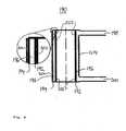
- Figure 8shows a combined generator 240 in accordance with a further embodiment of the invention.
- the combined generator 240is similar to that of figure 7 , apart from a modification which has been made to the NO x outlet pipe 242.
- the NO x generator 244has a Venturi tube 246 running through the hollow centre of the generator.
- the Venturi tube 246has an opening 247 at its constriction.
- the Venturi tube 246is connected to a supply of oxygen 248 at an upstream end and to the NO x outlet pipe 242 at a downstream end.
- the NO x outlet pipe 242runs through the hollow centre of the ozone generator 220 and out of the combined generator 240.
- the NO x annular channel 245is connected at one end to the NO x source gas inlet pipe 198.
- the annular channel 245leads into a chamber 249 which surrounds the Venturi tube 246.
- NO x gas generated by electric discharges across the annular channel 245is drawn through the chamber 249 and into the Venturi tube 246 via the opening 247, as a result of the pressure drop at the constriction as the oxygen gas flows therethrough.
- the Venturi tubeis preferably configured to provide a pressure drop of 1.2 kPa (9 mmHg) and thereby to draw the NO x gas through the opening 247 at a rate of between 30 and 40 ml/min. This is advantageous in that it is not necessary to provide an additional pump for the NO x gas flow.
- the oxygen supply 248is that which feeds into a combustion chamber as the standard combustion gas supply line. In that way, the oxygen supply line is simply opened up and diverted through the combined generator 240 on its way to the combustion analyser. This means that a separate inlet port for the NO x gas into the combustion chamber is not necessary, since the NO x is supplied into the chamber with the usual oxygen supply.
- the NO x generatormay be operated at room temperature. However, it has been found that increasing the temperature of the generator by around 10°C above room temperature results in a corresponding increase in the yield of NO x from the generator. Similar benefits are expected from a working temperature for the generator of up to 40-50°C. This is probably down to an increase in the reaction speed for NO x generation and/or the removal of moisture from the system due to the higher temperatures. It has been found that moisture in the outlet of the NO x generator can effectively reduce the NO x levels almost down to base levels, probably by reacting with the NO x to form nitric acid.
- heat evolved from other parts of the combustion analyseris transferred to the generator in order to heat it.
- the heatmay be that from an ozone killer unit.
- NOformed from NO x pumped into the combustion analyser
- total sulphur combustion analyserscannot make absolute measurements because the sulphur in a sample is not completely converted into SO 2 .
- a calibration curveis therefore necessary and it is important that the known, standard samples used to obtain the calibration curve are analysed under the same conditions as unknown samples, otherwise the results will not be accurate.
- liquid yield improversuch as pyridine, benzonitrile and 2-ethylhexyl nitrate
- gaseous yield improvermay be supplied to the combustion chamber before and/or during combustion.
- a sulphur dioxide yield improvementis achieved when the proportion of yield improver is greater than an expected proportion of sulphur in the combustion analyser.
- Figure 4shows that a relative proportion of yield improver to expected sulphur of 2 to 1 or above provides a significant yield improvement. Between 4 and 5 to 1, the yield of sulphur dioxide does not increase so rapidly, but starts to level off. Nonetheless, for certain types of sample or entirely unknown samples, it may be preferable to supply yield improver to the combustion analyser with a ratio of yield improver to expected sulphur proportions of up to 25-50 to 1, or even 100 to 1. For example, with a low-range detector, detecting around 0 to 100 ppm sulphur, an abundance of yield improver may be considered to be present in the combustion analyser, when there is around 1000 ppm of the yield improver.
- the yield improveris supplied before or during combustion. It is most logical to supply the yield improver into the combustion chamber 82, either directly or indirectly.
- the preferred flow rate for the oxygen into the ozone generatoris set by a flow controller to be 50 ml/min.
- the ozone flow ratemay be between approximately 0.5 and 1 ml/s, or any other suitable flow rate for removing interfering nitrogen monoxide from the combustion products.
- the inventionmay be applied to all combustion analysis instruments, which detect total sulphur by measuring sulphur dioxide levels. This applies to dedicated total sulphur instruments, which are configured only to measure total sulphur. This also applies to multi-use instruments, which are configured to detect total sulphur as well as other components of a sample. For example, total sulphur and total nitrogen instruments are known and this invention may be applied to them.
- a TS + TN instrumentmay be configured firstly to combust a first sample, secondly to measure the total sulphur in that first sample, and thirdly to measure the total nitrogen in that first sample.
- the instrumentmay be configured to combust a first sample and detect the total sulphur in that first sample, then to combust a second sample and to detect the total nitrogen in that second sample, where the first and second samples are of identical composition.
- the total sulphurmust be measured before the total nitrogen. This is because sulphur dioxide is adsorbed by the material, stainless steel, used in the detector tubing and chamber for a total nitrogen detector. Accordingly, if the total nitrogen were measured first, the subsequent total sulphur measurement would be compromised. As such, where total sulphur is measured, with added nitrogen monoxide to improve the yield and added ozone to remove the nitrogen monoxide, a total nitrogen measurement is not then possible, since substantially all of the nitrogen monoxide in the combustion products is removed by the ozone.
- the combustion analyseris therefore preferably switchable, so that the addition of a yield improver and/or supply of ozone may be turned on and off, as desired.
- a first samplecan be analysed with the option on, so improving the detection of sulphur dioxide; and a second, identical sample can be analysed with the option turned off, so that total nitrogen may be measured.
- the total sulphurcould also be measured at the same time, but this measurement would suffer from the possible problems of inconsistent sulphur dioxide yield and nitrogen monoxide interference.
- the inventionmay be employed for various applications in, for example, the chemical, refinery, hydrocarbon, petrochemical, and food and beverage sectors.
- the inventionmay be used in the analysis of solid, high-viscosity, liquid or gaseous samples.
- the inventionmay be used in the analysis of refinery products, such as gasoline and diesels.
Landscapes
- Chemical & Material Sciences (AREA)
- Engineering & Computer Science (AREA)
- Physics & Mathematics (AREA)
- Health & Medical Sciences (AREA)
- Life Sciences & Earth Sciences (AREA)
- Combustion & Propulsion (AREA)
- Organic Chemistry (AREA)
- Analytical Chemistry (AREA)
- Biochemistry (AREA)
- General Health & Medical Sciences (AREA)
- General Physics & Mathematics (AREA)
- Immunology (AREA)
- Pathology (AREA)
- Molecular Biology (AREA)
- Plasma & Fusion (AREA)
- Inorganic Chemistry (AREA)
- Chemical Kinetics & Catalysis (AREA)
- Investigating Or Analyzing Non-Biological Materials By The Use Of Chemical Means (AREA)
- Investigating Or Analysing Materials By The Use Of Chemical Reactions (AREA)
- Treating Waste Gases (AREA)
Abstract
Description
- The invention relates to an apparatus and method for generating nitrogen oxides in the combustion analysis of samples comprising a proportion of sulphur.
- Combustion analysers are used to determine the concentration of one or more components of a sample, by combusting the sample and analysing the gaseous products for specific oxides. Typically, the carbon, sulphur and/or nitrogen content of the sample is measured by detecting CO2, SO2 and NO, respectively.
- A schematic illustration of a typical combustion analyser is shown in
figure 1 . Thecombustion analyser 10 comprises asample introduction stage 20, acombustion stage 30, aconditioning stage 40, and adetection stage 50. Thesample introduction stage 20 comprises asample introduction apparatus 22, to which are connected a supply of asample 24, a supply ofoxygen 26 and a supply ofargon 27. Thesample introduction apparatus 22 introduces these fluids into acombustion chamber 32 in a suitable form for combustion to take place. A further supply ofoxygen 25 may be provided, directly into thecombustion chamber 32. Thecombustion chamber 32 is heated by anelectric heater 34, so that the sample is delivered into an oxygen-rich atmosphere at high temperature, typically of around 1000°C. The sample is thereby converted into various combustion products, such as CO2, H2O, SO2, NO, etc. The combustion products leave thecombustion chamber 32 and pass through theconditioning stage 40, where processes such as cooling, filtering, drying, etc. take place. The conditioned products then pass through one or morededicated detectors detection stage 50, aswaste products 56. - The performance of such a combustion analyser 10 - in terms of its suitability, reliability, accuracy and robustness - depends strongly on its ability to convert the element(s) of interest in a sample into its/their respective oxide (s).
- For combustion analysis of a sample containing sulphur, the combustion product to be detected is sulphur dioxide (SO2). The achievable yield of SO2 which may be detected with current combustion analysers is around 90%. The yield is the proportion of the amount of sulphur originally contained in the sample which is actually converted to sulphur dioxide. The achievable yield of a combustion analyser is calculated by analysing known, standard samples for calibration purposes. Once a calibration curve has been measured using standard samples, unknown samples may be analysed and the detected values may be calibrated accordingly. However, samples and also combustion conditions in a combustion analyser are subject to variation, with the result that the calibration curve cannot consistently provide accurate measurements from sample to sample.
- Also, current compliance regulations for sulphur in petrochemical fuels mean that total sulphur specifications (i.e., the permissible amount of sulphur in any form) are at low parts per million (ppm) levels and are heading ever lower, towards sub-ppm levels. For example, diesel specifications for sulphur are soon expected to be 10 ppm in the EU and 15 ppm in the US; for gasoline (petrol), the specifications are expected to be 10 ppm in the EU and 80 ppm in the US. It is therefore increasingly important to be able to measure sulphur concentrations at such low levels.
- Accordingly, it would be desirable to provide an improved apparatus and method for use in the combustion analysis of samples containing sulphur. A prior art combustion analyser is known from
US 2005/0074365 . US 4,879,246 relates to a device for the mineralization of carbonaceous material by heating a solid sample to 300-400°C for 6-20 hours in a stream of oxygen and ozone/nitrogen oxides/chlorine. Ashes are formed as the resulting mineralization product and these are dissolved for chemical analysis.GB 269,046 - According to the invention, there is provided a combustion analyser for combustion analysing a sample by combusting the sample and analysing the gaseous products, the analyser comprising: a combustion chamber for receiving a sample for combustion therein to form said gaseous combustion products; a fluid supply apparatus for supplying one or more fluids into the combustion chamber; and a detector for detecting SO2 in said gaseous combustion products; characterised in that the fluid supply apparatus comprises a nitrogen oxides (NOx) generating apparatus and the fluid supply apparatus is arranged to supply NOx into the combustion chamber.
- It has been found that nitrogen monoxide acts as a sulphur dioxide yield improver in the combustion analyser. When added to the combustion analyser, the nitrogen monoxide increases the yield of sulphur dioxide in the combustion products to be detected, relative to the yield of sulphur dioxide in the combustion products which would result when the substance is not added to the combustion analyser. As such, with samples of low sulphur concentration, a greater quantity of sulphur dioxide, for a given sample volume or mass, can be produced, offering improved detection. Furthermore, depending on the amount of nitrogen monoxide used for a particular sample, it is possible to provide a consistently greater yield of sulphur dioxide from the sample than previously achievable. Thus, the effect of variations between samples and variations in other combustion conditions can be reduced, if not minimised. This can help to ensure that measurements made using the calibration curve are accurate from sample to sample.
- NOx refers generally to oxides of nitrogen, which typically include nitrogen monoxide (NO), nitrogen dioxide (NO2), dinitrogen trioxide (N2O3) etc., in various proportions. In operation, at temperatures generally reached in a combustion chamber (around 1000°C), substantially all oxides of nitrogen are formed into nitrogen monoxide, so the NOx generated and supplied into the combustion analyser serves as a source of nitrogen monoxide yield improver.
- Preferably, the NOx is supplied to the combustion analyser before and/or during combustion of the sample. This allows the NO to have effect while the combustion products are being formed, to help improve the yield from the outset of the combustion process. The mechanism by which the NO improves the yield of sulphur dioxide in the combustion gases may be such that the NO reduces sulphur trioxide to sulphur dioxide, or inhibits the formation of sulphur trioxide, or promotes the formation of sulphur dioxide, or a combination of these. Accordingly, it is preferred that the NOx be supplied before or during combustion of a sample, to allow the NO to have sufficient opportunity to have effect.
- The NOx may be supplied to the combustion chamber of the combustion analyser via a dedicated inlet. Thus, the NOx gases may be pumped directly into the combustion chamber. Again, such supply may take place before and/or during combustion.
- Typically, combustion chambers have one or more inlet ports for receiving a supply of oxygen and a carrier gas, such as argon, respectively. For simple application of the invention to existing combustion analysers, the NOx may be connected to the supply line for oxygen or a carrier gas, and carried into the combustion chamber therewith. The connection may be made anywhere along such supply line and is preferably in the form of a two-into-one connector (such as a 'T' piece).
- Preferably, the connector or the apparatus connecting the NOx to a dedicated inlet, or to an oxygen supply line or a carrier gas supply line, is switchable between an on and an off state, so that during analysis of samples for which the NO yield improver is not required, the supply of the NOx may be stopped.
- The provision of a NOx generator allows for a relatively simple technique for supplying a source of NO into the analyser. A NOx generator may most simply be provided by modifying an ozonator to receive a supply of nitrogen and oxygen, instead of pure oxygen. With the use of a NOx generator, it is not necessary to spike or dilute a liquid sample with a nitrogen-containing compound, which process is labour intensive. The NOx produced may most straightforwardly be supplied into one or other of the gas supply lines. This allows for retrofitting of the NOx generator to existing combustion analysers. It is also not necessary to provide a modified combustion chamber, in this case.
- One particular advantage of the invention is that it is possible to use air (preferably first conditioned) as the supply of nitrogen and oxygen. Air intakes for ozonators typically condition the air by removing nitrogen, among other components. However, in embodiments of this invention, the nitrogen is not removed.
- Preferably, the NOx generator is operated at a slightly elevated temperature, say between 10 and 30°C above room temperature. This has been found to improve the yield of NOx from the generator.
- Samples for combustion analysis may be petrochemicals, high-grade chemicals, or food and beverage specimens, for which the concentration of sulphur in the sample may be subject to regulation, so that at least an estimated, or expected, proportion of sulphur may be known before combustion analysis. If the proportion of sulphur is entirely unknown, a first quantity of the sample may be analysed, to obtain an indication of the proportion of sulphur, so that an expected proportion of sulphur may be known for subsequent analyses. Preferably, the amount of NOx supplied to the combustion analyser is such that a proportion of NO yield improver in the combustion analyser is greater than the expected proportion of sulphur in a sample. Advantageously, the proportion of NO yield improver to the expected proportion of sulphur is greater than 2 to 1. Preferably still, the proportion is greater than 4 to 1. It has been found that, with tests using standard samples, adding a greater proportion of NO yield improver than the expected (in the case of a standard sample, the known) proportion of sulphur increases the yield of sulphur dioxide. Above a ratio of NO yield improver to sulphur of about 4 or 5 to 1, it has been found that the yield of sulphur dioxide does not increase so rapidly but starts to level off. By relative proportions, or ratios, of NO to SO2 is meant molar proportions/ratios, and not proportions/ratios based on volume or mass.
- It is considered that, for most samples, a proportion of NO yield improver to the expected proportion of sulphur of up to 1000 to 1 would be sufficient to ensure that an increased and substantially consistent yield of sulphur dioxide is achieved, even taking into account potentially significant variations in the actual proportion of sulphur in different samples. In most cases, a proportion of NO yield improver to the expected proportion of sulphur of up to 25-50 to 1 would be more than sufficient. Indeed, a ratio of 5 to 1 may be preferable, for example, where large variations in the sulphur content are not expected between samples.
- Since nitrogen monoxide, or a source thereof, is added to the analyser, the combustion products at the detector may comprise nitrogen monoxide. The inventors have found that nitrogen monoxide interferes with the detection of sulphur dioxide, when using a UV fluorescence detector. It is therefore preferable to provide an ozone supply to the combustion products, prior to detection, where nitrogen monoxide would otherwise interfere. Ozone reacts with nitrogen monoxide to form nitrogen dioxide and oxygen, so may be used to remove the NO interference. The ozone is preferably added between the combusting step and the detecting step. The ozone may be added after the combustion chamber or to the detector, or to a location in between, such as the transfer tubing between the chamber and detector.
- In this case, an ozone supply apparatus may be fitted to an existing combustion analyser relatively straightforwardly, by adding a connection into the combustion products line between the combustion chamber and the detector. Preferably, the connector is a two-into-one connector, such as a 'T' piece or the like.
Preferably, the ozone is supplied at a rate of between approximately 0.5 to 1 ml/s. Preferably also, the connector or the ozone supply apparatus is switchable between an on and an off state, so that ozone is not supplied when not required. - Preferably, the NOx generating apparatus and the ozone supply apparatus are provided together by: an electric discharge generator having a discharge region and arranged to provide an electric discharge through the discharge region; a first, NOx conduit disposed in a first part of the discharge region and comprising a NOx source gas inlet for receiving a supply of NOx source gas into the NOx conduit and a NOx gas outlet for supplying NOx gas therefrom; a second, ozone conduit disposed in a second part of the discharge region and comprising an ozone source gas inlet for receiving a supply of ozone source gas into the ozone conduit and an ozone gas outlet for supplying ozone gas therefrom.
- In this way, both NOx and ozone can be produced using the same electric discharge device. This can provide a saving on components, as only one power supply and transformer is required to provide the electric discharges.
- Preferably, a Venturi tube with an oxygen flow therethrough is used to draw the generated NOx from the NOx generator into an inlet hole provided in the constriction of the Venturi tube.
- Preferably, the NOx generating apparatus comprises: an electric discharge generator having a discharge region and arranged to provide an electric discharge through the discharge region; a NOx conduit disposed in the discharge region and comprising a NOx source gas inlet for receiving a supply of NOx source gas into the NOx conduit and a NOx gas outlet for supplying NOx gas therefrom, wherein the NOx gas outlet comprises a Venturi tube having a tube constriction, an intake opening near the tube constriction, and a Venturi tube outlet downstream of the tube constriction, the Venturi tube being arranged to receive a fluid flow through the tube constriction such that NOx gas is drawn into the intake opening and supplied from the Venturi tube outlet.
- According to the invention, there is also provided a method of combustion analysing a sample by combusting the sample in a combustion chamber of a combustion analyser and analysing the gaseous products, the method comprising the steps of: supplying the sample to the combustion chamber; combusting the sample to produce combustion products; and detecting SO2 in the combustion products, characterised by the step of generating nitrogen oxides (NOx) and supplying the generated NOx to the combustion 5 chamber.
- Preferably the NOx and ozone are generated by providing a single electric discharge region; passing a mixture of nitrogen and oxygen through a first part of the region, to generate NOx; and passing oxygen through a second part of the region, to generate ozone.
- The invention, preferably uses an ozonator with a nitrogen and oxygen supply to generate NOx to be supplied to a combustion chamber of a combustion analyser for combustion analysing a sample by combusting the sample and analysing the gaseous products.
- The invention may be put into practice in a number of ways and some embodiments will now be described, by way of non-limiting example only, with reference to the following figures, in which:
Figure 1 shows a schematic layout of a typical, prior art combustion analyser;Figure 2 shows a schematic layout of a combustion analyser according to one embodiment of the invention;Figure 3 shows a schematic layout of a combustion analyser according to another embodiment of the invention;Figure 4 shows a graph, illustrating the effects of adding a nitrogen compound into the combustion analyser;Figure 5 shows a flow diagram illustrating the steps for generating NOx;Figure 6 shows a schematic cross section of a NOx generator according to one embodiment of the invention;Figure 7 shows a schematic cross section of a NOx and ozone generator according to another embodiment of the invention; andFigure 8 shows a schematic cross section of a NOx and ozone generator according to a further embodiment of the invention.- Referring to
figure 2 , there is shown a schematic layout of acombustion analyser 120, in accordance with one embodiment of the invention. Thecombustion analyser 120 has asample introduction apparatus 72, which includes asample supply inlet 74, anoxygen supply inlet 75, and a carriergas supply inlet 77. Thesample introduction apparatus 72 is connected to acombustion chamber 82, which is heated by aheater 84. Thecombustion chamber 82 is divided into two compartments, the second of which being a turbo compartment and having a furtheroxygen supply inlet 76, to promote complete combustion of a sample. - Combustion products formed in the
combustion chamber 82 pass through aconditioning stage 90, before detection. In this example, the conditioning stage includes adryer 92, which removes water from the combustion products, the water being entrained by a dry gas flow in the opposite direction to the combustion products, the dry gas flow flowing through an outer tube of the dryer. The conditioning stage also includes afilter 94. - The conditioned combustion products then pass through a
combustion product line 96 to adetector 150. - The
combustion analyser 120 has anoxygen supply line 130 connected to theoxygen supply inlet 75. The oxygen supply line has anend 132 for connection to an oxygen feed unit (not shown). Thecombustion analyser 120 has a carrier gas (typically argon)supply line 134 connected to the carriergas supply inlet 77. The carrier gas supply line has anend 136 for connection to a carrier gas feed unit (not shown). - Installed on both the oxygen and the carrier
gas supply lines gas supply lines supply lines Setting Oxygen supply line Carrier gas supply line A Oxygen Carrier gas B Oxygen & NOx Carrier gas C Oxygen Carrier gas & NOx D Oxygen & NOx Carrier gas & NOx - In other embodiments, there may be more than one connector, which may or may not be switchable, between the NOx generator 140 and the
oxygen supply line 130 and the carriergas supply line 134. In still others, a connector may be fitted only to one of thesupply lines - The NOx generator 140, in this embodiment, is configured to supply nitrogen oxide gases into one or both of the
supply lines oxygen supply line 130, a flow of oxygen passes intoend 132 and, from thesupply line 130, into thesupply inlet 75 and on into thecombustion chamber 82. A typical flow rate for the oxygen is between 200 and 400 ml/min. The NOx gas is pumped into theoxygen supply line 130 through the connector, where it mixes with the oxygen, for supply to the combustion chamber. A preferred flow rate for the NOx gas is between 15 and 50 ml/min. Such a flow rate is generally suitable to provide an abundance of NO in the combustion chamber before and/or during the combustion process, so that the yield of SO2 in the combustion products may be improved. - The combustion products formed in the combustion chamber 82 - including an improved yield of SO2 - are carried through the
conditioning stage 90 and along thecombustion products line 96, by a general, background flow of carrier gas or oxygen through theanalyser 120. From thecombustion products line 96, the combustion products are passed into one or more detectors 150 (not shown), one of which is configured to detect an amount of SO2 therein. - The
detector 150 for detecting SO2 can be any suitable detector and is not limited to a UV fluorescence detector. For example, thedetector 150 may be a coulometric detector using iodometric titration. In this case, the combustion gases containing SO2 are passed through the electrolyte of a titration cell, containing tri-iodide (I3-). The sulphur dioxide reacts with the tri-iodide to form a sulphate and iodide. This reaction changes the potential from its preset value of the cell and this is detected. At the anode, iodide is reduced to iodine, to compensate for the tri-iodide deficiency, by an applied current. The current is integrated over time, providing a measurement of the amount titrated sulphur dioxide, from which the amount of sulphur in the sample may be calculated. The reaction equations for this process are:
- Since the invention improves the detectable sulphur yield by increasing the yield of SO2 in the combustion gases, the invention may be applied to any combustion analyser employing a sulphur dioxide detection mechanism and provide corresponding advantages thereto.
- Normally, when a sulphur-containing substance is combusted, approximately 90% of the sulphur is formed into sulphur dioxide and approximately 10% is formed into sulphur trioxide (SO3). For this reason, most total sulphur detectors measure sulphur dioxide in one way or another. One common detector used is a UV fluorescence detector. Total sulphur ultraviolet (TSUV) detection is based on the principle that SO2 molecules fluoresce; i.e., absorb UV light, become excited, then relax to a lower energy state, emitting UV light at a specific wavelength in the process. The emitted light is detected to provide a measure of the amount of SO2 present.
- However, the inventors have recognised that the readings taken by the above type of detector are not a result purely of SO2 fluorescence. It has been found that the detector is unable to distinguish between SO2 and NO, since they both fluoresce upon excitation with UV light in generally the same wavelength range. Accordingly, the inventors have appreciated that measurements made by such a detector may indicate higher levels of SO2 than are actually present in the fluorescence chamber, since NO fluorescence can contribute to the detected signal. Many samples contain a proportion of nitrogen and so can be incorrectly quantified by the detector.
- Accordingly, a method and apparatus for removing the interfering nitrogen monoxide from the combustion products is now discussed, in accordance with one embodiment of the invention and with reference to
figure 3 . - When it is desired to measure the concentration of nitrogen in a sample, it is known to use a total nitrogen (TN) detector, as mentioned above. This is a chemiluminescence detector, which measures the amount of light emitted when excited nitrogen dioxide falls to its ground state. The excited nitrogen dioxide is formed from the reaction of nitrogen monoxide with ozone (O3). The reaction mechanism used in TN detectors has been applied in sulphur dioxide analysis.
Figure 3 shows schematically acombustion analyser 160, which is similar to that shown infigure 2 , but with some modifications. At the end of thecombustion products line 96, there is provided aUV fluorescence detector 100. Anozone generator 170 is installed on thecombustion products line 96 between thecombustion chamber 82 and thedetector 100, so that any nitrogen monoxide in the combustion products may react with the ozone and thereby be removed from the combustion products and not be detected by the sulphur dioxideUV fluorescence detector 100. An ozonator (also known as an ozonizer) is preferably employed as theozone generator 170.- The
ozone generator 170 is configured to supply ozone to thecombustion products line 96 at a rate sufficient to remove substantially all of the nitrogen monoxide. For example, an oxygen flow of 50 ml/min supplied to an ozonator has been found to be sufficient to remove the nitrogen monoxide formed from a nitrogen concentration in the combustion products of up to 9000 ppm. - The ozone mixed into the combustion products should preferably be supplied in a greater quantity than is needed to remove all NO gas, to help ensure substantially all NO gas is converted to NO2. Since ozone is toxic, it should preferably not simply be pumped to waste. Accordingly, the
combustion analyser 160 has awaste discharge line 58, which passes through or near to thecombustion chamber heater 84. In this way, ozone present in the waste products from thedetector 100 may be thermally dissociated into oxygen before being discharged from the analyser. Other techniques for ozone removal may alternatively be employed. - An experiment, using a combustion analyser corresponding to the
combustion analyser 160, and its results will now be discussed. The experiment is discussed with reference to table 1, below, andfigure 4 . In the experiment, a set of known, standard samples was prepared, as follows. Eight different samples were prepared and each sample contained 10 ppm of a sulphur-containing substance. The samples also contained the following concentration of a nitrogen-containing substance, respectively: 0, 3, 5, 10, 25, 50, 100, and 150 ppm. The nitrogen-containing substance used was pyridine in xylene. - A combustion analyser to detect SO2 by UV fluorescence detection was modified to allow it to operate under a number of different conditions. The analyser used was the SphiNCX analyser, manufactured by Thermo Fisher Scientific Inc.. The modifications made were to add a nitrogen oxides (NOx) generator to the oxygen supply line, by means of a switchable connector, and to add an ozone generator to the combustion products line, again by means of a switchable connector. The switchable connectors were used so that one or both of the supplies could be turned off, as required.
- The following methods of analysis were used with each of the eight samples, respectively. For method A, the analysis was conducted with both the NOx and O3 supplies turned off; that is, essentially, the SphiNCX analyser was operating in its standard manner according to international standard ASTM D5453 for total sulphur determination. For method B, the analysis was conducted with the O3 supply switched on and the NOx supply switched off. That is, the combustion process was as standard, but substantially all NO in the combustion products was removed. For method C, the analysis was conducted with both NOx and O3 supplies turned on. That is, the analysis was as standard, but a yield improver gas was supplied to the combustion chamber, along with the oxygen supply, and substantially all NO in the combustion products was removed. When the ozone generator was employed, the ozone gas flow rate into the combustion products line was 50 ml/min. When the NOx generator was employed, the NOx flow rate into the oxygen supply line was between 34 and 40 ml/min. The sulphur-containing liquid used was thiophene.
- The results of the tests are shown in table 1 and on the graph of
figure 4 . The results for method A generally show a rise in the detected concentration of total sulphur in the eight standard samples, with increasing nitrogen in the samples. With no added nitrogen-containing liquid in the sample (sample 1), the yield of SO2 was around 90%. The apparent yield of SO2 for sample 8 was around 110%, clearly confirming that the UV fluorescence detector was measuring a signal from an interfering substance (NO), in addition to the SO2.Table 1: Influence of added nitrogen with different methods of determining sulphur on 10 ppm sulphur. Added N/ppm 0 3 5 10 25 50 100 150 Detected A 9.01 8.99 8.98 9.12 9.40 9.90 10.64 11.04 S/ppm by B 8.74 8.88 8.94 9.19 9.41 9.61 9.69 9.59 method: C 9.43 9.53 9.58 9.81 9.88 9.97 9.92 9.75 - The results for method B do not show an ever-increasing detected concentration of total sulphur, with increasing nitrogen concentration in the samples. Provided sufficient ozone is mixed with the combustion products, substantially all NO can be removed from them. This means that the signal generated by the detector is substantially wholly from the fluorescence of SO2 and indicates that the actual yield of SO2 was around 87%. Accordingly, a calibration curve based on standard samples analysed using method B may be obtained and used to provide total sulphur measurements of unknown samples, without interference from NO in the detector.
- However, the yield of SO2 is not consistent across samples 1 to 8, but varies from around 87% to around 96%, as the nitrogen concentration in the samples varies. The yield does appear to level off at around 95-96% from nitrogen concentrations in the sample of about 40-50 ppm and, before that, there is a reasonable yield, of over 90%, for nitrogen concentrations above about 10 ppm.
- Nevertheless, the yield of SO2 is affected by variations in the concentration of nitrogen in the samples. Since, for actual samples, the concentration of nitrogen is unknown and may vary between samples, a calibration curve obtained under method B would be an improvement on one obtained under method A, but still could not assure consistent applicability.
- The results for method C are similar to those for method B, in that the detected concentration of total sulphur does not continue increasing with increasing added nitrogen concentration in the sample, but also levels out. However, the yield is shifted upwards for all samples and the levelling off of the yield occurs at lower sample concentrations of nitrogen. Also, the variation in detected sulphur concentrations across samples 1 to 8 is much reduced, giving a higher, more consistent yield of SO2. The increase in yield from method B to method C varies from around 2% to around 7%, perhaps averaging around a 4% increase. This confirms that the additional NO in the combustion chamber is acting to encourage the formation of SO2. The levelling off of the detected sulphur concentration takes place, at around 98-99%, from added nitrogen concentrations in the sample from around 20-40 ppm. The yield is considered to be good for all of the samples tested using the supplied NOx gas, whether or not a nitrogen-containing liquid was also added to the sample. The yield range, from around 94% to around 99%, is more consistent than that, of around 87% to around 96%, for method B.
- The fact that there is still some variation in the detected total sulphur concentration for the method C results may be due to a number of factors. General variations in the measurement conditions may have had an effect, as may variations in the conditions under which the eight samples were prepared. Also, this may be down to how readily the nitrogen monoxide was mixed with the sample during combustion. It may be that the nitrogen-containing liquid added to the sample itself enables the NO, once formed, to have its yield-improving effect on SO2 formation from the early stages of combustion, since it is already mixed with the sample. However, the NOx gas, which is pumped in and forms NO in the combustion chamber, first needs to mix with the sample while combustion is taking place. This may explain why the yield of SO2 is lower for lower concentrations of nitrogen-containing liquid in the sample, even though an additional supply of NO is provided to the combustion chamber as NOx gas, so that there is a relatively high overall concentration of NO in the chamber.
- It is often generally known what the total sulphur concentration in a sample is, before measurement. For example, the sample may be taken from a high-grade chemical, or a food or beverage, or a petrochemical, each of which has a pre-defined, allowable total sulphur concentration. Even if the expected total sulphur concentration is in a working range between 0 and 100 ppm, the initial flow rate of NO gas can be set to correspond to a concentration of around 4-5 times the expected sulphur concentration and then reduced (or increased, if appropriate) for subsequent analyses, once a first measurement of the total sulphur concentration has been made.
- For example, once a combustion analyser has been calibrated, any signal detected by a SO2 UV fluorescence detector will look like fluorescence from SO2, even if no sulphur-containing sample is being analysed. NO gives a signal on total sulphur detectors, but at a signal level of about 1/100th of that from sulphur dioxide (i.e., 100 ppm NO is 'seen' as about 1 ppm SO2). Accordingly, if the working range of the analyser is configured to detect total sulphur levels between 0 and 100 ppm, an initial flow rate for the NOx gas into the analyser can be set so that the SO2 detector measures a signal which looks like 4 ppm or more SO2 (i.e., about 400 ppm of NO, which is around 4-5 times the expected total sulphur concentration). However, of course, the detected signal is not from SO2, but from the deliberate NO interference passing into the detector. In practice, a pre-determined signal on the SO2 detector will be known to represent a sufficient flow rate of NOx into the analyser for any particular analysis regime. For example, the inventors have implemented the above embodiments by modifying a TS3000 combustion analyser, manufactured by Thermo Fisher Scientific Inc.. It has been found that an arbitrarily selected signal level of 300 mV on the SO2 UV fluorescence detector indicates that there is a sufficient flow of NOx gas into the analyser, to improve the SO2 yield. Even with minor variations in the generation efficiency - so that, for example, the signal level may fluctuate by +/- 20-40 mV, there is generally a sufficient quantity of NO in the combustion chamber to have the desired yield improving effect.
- In some of the tests discussed above, an ozone feed unit was employed to remove any NO present in the combustion gases, before they were detected. Such a feed unit is not required when the
detector 150, used to detect the SO2 concentration, is not affected by NO interference. For example, it would not be required when a coulometric detector is used. Furthermore, it may be desirable not to mix ozone with the combustion products, even when a UV fluorescence detector is used. This may be so that evaluation or reference measurements may be made, or so that a total nitrogen chemiluminescence detector may be employed following the SO2 detector. - Having said that, where a
UV fluorescence detector 100 is used, it is preferable to add anozone feed unit 170 onto thecombustion products line 96, as shown infigure 3 . - As described above, the yield improver may be provided by nitrogen monoxide gas or NOx gas. The gaseous yield improver may be pumped directly into the combustion chamber, via a dedicated inlet. Such inlet may be similar to that used for the
additional oxygen supply 76, although the dedicated inlet for the yield improver may be located at any suitable position at either end of thecombustion chamber 82. Alternatively, and more straightforwardly, the gaseous yield improver may be supplied into one of the oxygen or carriergas supply lines - A NOx generator may be provided based on the principles of an ozonator. An ozonator (also known as an ozonizer) is an apparatus for the preparation of ozone by passing oxygen through an electrical discharge. The electrical discharge provides energy to break O2 molecules, which are then able to re-form as O3 molecules. The electrical discharge used is variously known as a silent discharge, a corona discharge, and a brush discharge, and is essentially a low-current electric discharge across a gas-filled gap, with a relatively high voltage gradient.
- It has been found that passing nitrogen and oxygen through such an electrical discharge can produce sufficient quantities of NOx to be used as a source of nitrogen monoxide for the combustion analyser. Advantageously, ambient air (preferably filtered and dried) can be used as the source of the nitrogen and oxygen into the ozonator.
Figure 5 shows a flow diagram of the steps which may be taken to generate NOx. In step 1 (180), a supply of nitrogen and oxygen is provided to the generator. In step 2 (181), depending on the source of the NOx source gases, they may need to be conditioned. For example, the gases may need to be dried, to remove any moisture, and filtered, to remove any particulate matter, such as dust. A suitable absorbent material for drying the NOx source gases is silica gel. A suitable filter is a PTFE particulate micro filter. Other types of conditioning may additionally or alternatively be used, as appropriate.- In step 3 (182,183), the (conditioned) gases enter an electric discharge region. The NOx generator includes a power and control unit, which applies an alternating voltage signal, through a transformer, to a first electrode. A second electrode, separated from the first electrode by a gap which provides the discharge region, may be connected to ground. Alternatively, a positive voltage peak my be applied to one electrode while a corresponding, negative voltage peak is applied to the other. In one embodiment, the power supply provides the transformer with approximately 55 Hz, 15 V pulses, which the transformer steps up to around 15 kV. Typically, however, the voltages applied to the electrodes are between 5 and 15 kV, with frequencies ranging from 50-60 Hz (mains supply), up to between 400 Hz and 1 kHz. The currently preferred supply values are a frequency of 200 Hz, with a half period in which +6 kV is applied to one electrode, then a half period in which -6 kV is applied to the other electrode. This results in a peak-to-peak voltage of 12 kV.
- As the current discharges between the first electrode and the second electrode, some of the nitrogen and oxygen molecules are dissociated and ionised. Recombination of the excited species produces nitrogen oxides (NO, NO2, N2O3 etc., or NOx) and ozone (O3), as shown in step 4 (184), as well as oxygen. The generated NOx is then supplied to the combustion analyser, where most of it will form NO at the temperature of the combustion chamber. Although such a NOx generator may not be highly consistent in its NOx generation efficiency, this is generally not a problem for the intended application, since the amount generated is considered to be sufficient to enable the desired sulphur dioxide yield improvement to be achieved.
- As mentioned above, the NOx source gas may simply be air, which typically comprises around 80% of nitrogen and around 20% of oxygen. Alternatively, the gas may be a mixture of nitrogen and oxygen from gas bottles, preferably at a ratio of N2 to O2 of greater than 50:50. However, given the added cost and potential hazard of using gas bottles, and the simplicity of using air, the latter is preferred. The NOx source gas may be pumped into the NOx generator, or may be drawn into it, using the pressure drop of the combustion analyser itself or of a dedicated suction device.
- In applications where the NO yield improver is not required, the NOx generator may be switched off so that it becomes a passive part of the fluid supply apparatus of the combustion analyser. In that way, any nitrogen and oxygen passing through the (de-activated) electric discharge region will remain unaffected and enter the combustion chamber unchanged. At typical temperatures of the combustion chamber, nitrogen remains stable and does not affect measurements of the combustion products. The oxygen will simply provide an additional amount of combustion gas in the chamber. Alternatively, the outlet to the NOx generator may be closed off by a valve, so that no gas passes into the combustion chamber from the NOx generator.
Figure 6 shows a NOx generator 190 according to one embodiment of the invention. The NOx generator 190 is provided by a double-tube arrangement. That is, afirst tube 192 is surrounded by a coaxial,second tube 194, the second tube having a larger diameter than that of the first tube. As such, anannular channel 196 is formed between the two tubes 192,194. Aninlet pipe 198 is provided for supplying NOx source gas (nitrogen and oxygen) into thechannel 196. Anoutlet pipe 200 is provided for receiving generated NOx gas from thechannel 196. The inlet and outlet pipes 198,200 are at extremities of the NOx generator, to provide a large volume of thechannel 196 over which NOx generation may take place. However, it is not important which way round the inlet and outlet pipes are configured. The NOx source gas enters theannular channel 196 from theinlet pipe 198 at one end, fills the channel around its circumference and along its length, is subjected to electric discharges, and leaves the channel out of theoutlet pipe 200, comprising a proportion of NOx.- The tubes 192,194 and pipes 198,200 are preferably made from glass. The radial distance between an outer surface of the
first tube 192 and an inner surface of thesecond tube 194 is between 0.5 and 5 mm, preferably between 1 and 2 mm. The currently preferred distance is 1.6 mm. - The double-tube arrangement is approximately 60 mm high and has a diameter of around 25 mm. The
annular channel 196 between thetubes outlet pipes - The inside of the
first tube 192 is hollow. Applied to the inner surface of thefirst tube 192 is ametallic film coating 202, preferably of silver. Thecoating 202 extends around the inner circumference and along the length of thetube 192 so as to provide a cylindrical, first electrode. Applied to the outer surface of thesecond tube 194 is a similarmetallic film coating 204, providing a generally cylindrical, second electrode. In this way, the electrodes do not come into contact with the gases passing through the NOx generator. A portion of the NOx generator has been enlarged in a circle, for added clarity. A power and control unit (not shown) is connected to the first and second electrodes and is arranged to apply an appropriate voltage waveform thereto, in order to effect an electric discharge across theannular channel 196 between the electrodes. - The frequency of the applied waveform has a strong influence on the yield of generated NOx. The currently preferred waveform has +/-6 kV peaks and a frequency of 200 Hz. It is also possible to change the yield of generated NOx by controlling the gas flow speed through the NOx generator 190. The preferred flow rate of NOx source gas into the NOx generator 190 is around 40 ml/min. Other operational parameters and conditions are similar to those described with reference to
figure 5 , so no further discussion is given here. - One implementation of the above embodiment has been made, using a standard ozonator normally employed for the generation of ozone. The ozonator was modified to receive a supply of nitrogen and oxygen, instead of purely oxygen. Other operational configurations and conditions are as for the NOx generator of
figure 6 . The ozonator used was taken from the model 42C trace level NO-NO2-NOx analyser, manufactured by Thermo Fisher Scientific Inc.. - With the above NOx generators, if it is desired to remove any NO present in the combustion gases, a further ozonator needs to be employed. In this case, the ozonator is configured as a standard ozonator; i.e. with a supply of (bottled) oxygen gas, at around 95% purity.
Figure 7 shows a NOx generator 210 in accordance with a further embodiment of the invention, in which the generator is not only configured to generate NOx, but also to generate ozone. In this figure, similar or identical parts are labelled with the same reference numerals as those used infigure 6 . In this combinedgenerator 210, a NOx generator 190 is mounted axially adjacent anozone generator 220. While infigure 7 , the NOx generator 190 is shown as being disposed vertically above theozone generator 220, it is not important which way round the generators are disposed.- The combined
generator 210 has afirst tube 212 surrounded by a coaxial,second tube 214, the first and second tubes being of similar dimensions to those stated above with reference tofigure 6 . However, thetubes first electrode 216 extends around and along substantially the entire inner surface of thefirst tube 212. Similarly, asecond electrode 218 extends around and along substantially the entire outer surface of thesecond tube 214. - However, an annular channel does not run along the entire length of the combined
generator 210. Alateral partition 222, in the form of an annulus in this embodiment, is disposed midway along the combinedgenerator 210, to separate the annular space between the twotubes annular channel 224 and a second, ozoneannular channel 226. - The NOx
annular channel 224 has aninlet pipe 198 and anoutlet pipe 200. The ozoneannular channel 226 has aninlet pipe 228 for supplying oxygen into the channel. Thechannel 226 also has anoutlet pipe 230 for receiving generated ozone gas from the channel. The NOx outlet pipe 200 is connected into a fluid supply apparatus for supplying the NOx to a combustion chamber of a combustion analyser. Theozone outlet pipe 230 is configured to supply the ozone into the combustion products line connecting the combustion chamber to a detector. - A single power and control unit (not shown) is connected to the first and
second electrodes annular channels - Thus, a distinct NOx generator and a distinct ozone generator are provided with a single, shared,
first electrode 216 and a single, shared,second electrode 218 and a single, shared power and control unit. With this combinedgenerator 210, it is possible to generate both NOx and ozone. A saving is therefore made, since it not necessary to employ two independent power and control units, which each include a transformer and a printed circuit board (PCB). Instead, a single power and control unit is able to operate the combinedgenerator 210. - It has been found that the combined
generator 210 is able to function effectively - i.e. produce sufficient yields of NOx and ozone - even if the power and control unit is configured to operate in exactly the same manner as it is for a single ozonator. It may be that the efficiency of NOx and ozone production is not as high compared with a single NOx generator or a single ozone generator operated by such a power and control unit. However, it is considered to be more than adequate for the purposes of NOx generation to provide NO yield improver and ozone generation to remove unwanted downstream NO interferences. If it were desired to maintain the same efficiency of NOx generation and of ozone generation as compared with their entirely separate generation, the combinedgenerator 210 would require more power. Figure 8 shows a combinedgenerator 240 in accordance with a further embodiment of the invention. The combinedgenerator 240 is similar to that offigure 7 , apart from a modification which has been made to the NOx outlet pipe 242. In this embodiment, the NOx generator 244 has aVenturi tube 246 running through the hollow centre of the generator. TheVenturi tube 246 has anopening 247 at its constriction. TheVenturi tube 246 is connected to a supply of oxygen 248 at an upstream end and to the NOx outlet pipe 242 at a downstream end. The NOx outlet pipe 242 runs through the hollow centre of theozone generator 220 and out of the combinedgenerator 240. The NOxannular channel 245 is connected at one end to the NOx sourcegas inlet pipe 198. At the other end, theannular channel 245 leads into achamber 249 which surrounds theVenturi tube 246. NOx gas generated by electric discharges across theannular channel 245 is drawn through thechamber 249 and into theVenturi tube 246 via theopening 247, as a result of the pressure drop at the constriction as the oxygen gas flows therethrough. Thus a mixture of NOx gas and oxygen leaves theVenturi tube 246 and is supplied from the NOx outlet pipe 242 into a combustion chamber. The Venturi tube is preferably configured to provide a pressure drop of 1.2 kPa (9 mmHg) and thereby to draw the NOx gas through theopening 247 at a rate of between 30 and 40 ml/min. This is advantageous in that it is not necessary to provide an additional pump for the NOx gas flow.- In a preferred arrangement of the above embodiment, the oxygen supply 248 is that which feeds into a combustion chamber as the standard combustion gas supply line. In that way, the oxygen supply line is simply opened up and diverted through the combined
generator 240 on its way to the combustion analyser. This means that a separate inlet port for the NOx gas into the combustion chamber is not necessary, since the NOx is supplied into the chamber with the usual oxygen supply. - The NOx generator, or the combined ozone and NOx generator, may be operated at room temperature. However, it has been found that increasing the temperature of the generator by around 10°C above room temperature results in a corresponding increase in the yield of NOx from the generator. Similar benefits are expected from a working temperature for the generator of up to 40-50°C. This is probably down to an increase in the reaction speed for NOx generation and/or the removal of moisture from the system due to the higher temperatures. It has been found that moisture in the outlet of the NOx generator can effectively reduce the NOx levels almost down to base levels, probably by reacting with the NOx to form nitric acid.
- Preferably, heat evolved from other parts of the combustion analyser is transferred to the generator in order to heat it. For example, the heat may be that from an ozone killer unit.
- Various modifications of the above NOx generators and combined NOx and ozone generators are envisaged and provide further embodiments of the invention. For example, the Venturi tube arrangement is described above with reference to a combined generator, but may alternatively be used with a single NOx generator to similar effect.
- It has been shown that NO, formed from NOx pumped into the combustion analyser, increases the yield of SO2 in the combustion products. It has also been shown that, by mixing ozone with the combustion products prior to detection, it is possible to remove substantially all NO (whether from the sample or added NOx gas) from the combustion products. According to embodiments of the invention, then, it is possible to increase the SO2 yield and to improve the accuracy of the SO2 detection.
- Since variations in the amount of nitrogen monoxide in the analyser affect the yield of SO2, it is preferable to supply NOx to the analyser in sufficient quantities that any variations in the composition of the (unknown) samples have a negligible effect on the yield of SO2, since the influence of the supplied NO on the yield will be much more significant.
- As stated above, total sulphur combustion analysers cannot make absolute measurements because the sulphur in a sample is not completely converted into SO2. A calibration curve is therefore necessary and it is important that the known, standard samples used to obtain the calibration curve are analysed under the same conditions as unknown samples, otherwise the results will not be accurate. By providing an excess concentration of NO in the analyser, preferably around 4-5 times the expected concentration of sulphur in the sample, not only a substantially consistent yield, but also an increased yield, of SO2 may be achieved. This principle applies to all total sulphur combustion analysers.
- As already described with some of the embodiments above, more than one technique for supplying the yield improver to the combustion analyser may be used together, if desired. For example, liquid yield improver (such as pyridine, benzonitrile and 2-ethylhexyl nitrate) may be added to the sample before detection and gaseous yield improver may be supplied to the combustion chamber before and/or during combustion.
- As shown empirically in the above experiment, a sulphur dioxide yield improvement is achieved when the proportion of yield improver is greater than an expected proportion of sulphur in the combustion analyser.
Figure 4 shows that a relative proportion of yield improver to expected sulphur of 2 to 1 or above provides a significant yield improvement. Between 4 and 5 to 1, the yield of sulphur dioxide does not increase so rapidly, but starts to level off. Nonetheless, for certain types of sample or entirely unknown samples, it may be preferable to supply yield improver to the combustion analyser with a ratio of yield improver to expected sulphur proportions of up to 25-50 to 1, or even 100 to 1. For example, with a low-range detector, detecting around 0 to 100 ppm sulphur, an abundance of yield improver may be considered to be present in the combustion analyser, when there is around 1000 ppm of the yield improver. - Preferably, the yield improver is supplied before or during combustion. It is most logical to supply the yield improver into the
combustion chamber 82, either directly or indirectly. - Where ozone is added to the combustion analyser, the preferred flow rate for the oxygen into the ozone generator is set by a flow controller to be 50 ml/min. However, the ozone flow rate may be between approximately 0.5 and 1 ml/s, or any other suitable flow rate for removing interfering nitrogen monoxide from the combustion products.
- The invention may be applied to all combustion analysis instruments, which detect total sulphur by measuring sulphur dioxide levels. This applies to dedicated total sulphur instruments, which are configured only to measure total sulphur. This also applies to multi-use instruments, which are configured to detect total sulphur as well as other components of a sample. For example, total sulphur and total nitrogen instruments are known and this invention may be applied to them.
- A TS + TN instrument may be configured firstly to combust a first sample, secondly to measure the total sulphur in that first sample, and thirdly to measure the total nitrogen in that first sample. Alternatively, the instrument may be configured to combust a first sample and detect the total sulphur in that first sample, then to combust a second sample and to detect the total nitrogen in that second sample, where the first and second samples are of identical composition.
- Where the same combustion sample is detected by both detectors, the total sulphur must be measured before the total nitrogen. This is because sulphur dioxide is adsorbed by the material, stainless steel, used in the detector tubing and chamber for a total nitrogen detector. Accordingly, if the total nitrogen were measured first, the subsequent total sulphur measurement would be compromised. As such, where total sulphur is measured, with added nitrogen monoxide to improve the yield and added ozone to remove the nitrogen monoxide, a total nitrogen measurement is not then possible, since substantially all of the nitrogen monoxide in the combustion products is removed by the ozone. The combustion analyser is therefore preferably switchable, so that the addition of a yield improver and/or supply of ozone may be turned on and off, as desired. A first sample can be analysed with the option on, so improving the detection of sulphur dioxide; and a second, identical sample can be analysed with the option turned off, so that total nitrogen may be measured. For the second sample, the total sulphur could also be measured at the same time, but this measurement would suffer from the possible problems of inconsistent sulphur dioxide yield and nitrogen monoxide interference.
- In view of the fact that total sulphur detection must take place before total nitrogen detection in a combined combustion analyser, the introduction of an ozone feed unit to the combustion products line leading to the SO2 detector and the addition of ozone to the combustion products before detection by the SO2 detector are considered to be new and advantageous aspects of the invention.
- The invention may be employed for various applications in, for example, the chemical, refinery, hydrocarbon, petrochemical, and food and beverage sectors. The invention may be used in the analysis of solid, high-viscosity, liquid or gaseous samples. In particular, the invention may be used in the analysis of refinery products, such as gasoline and diesels.

Claims (24)
- A combustion analyser (120, 160) for combustion analysing a sample by combusting the sample and analysing the gaseous products, the analyser comprising:a combustion chamber (82) for receiving a sample for combustion therein to form said gaseous combustion products;a fluid supply apparatus (72) for supplying one or more fluids into the combustion chamber; anda detector (150) for detecting SO2 in said gaseous combustion products;characterised in that the fluid supply apparatus comprises a nitrogen oxides (NOx) generating apparatus (140) and the fluid supply apparatus is arranged to supply NOx into the combustion chamber.
- The analyser (120, 160) of claim 1, wherein the NOx generating apparatus (140) comprises an electric discharge generator having a discharge region, the electric discharge generator being arranged to receive a supply of nitrogen and a supply of oxygen in the discharge region and to provide an electric discharge through the discharge region such that NOx is generated.
- The analyser (120, 160) of claim 2, wherein the supply of nitrogen and the supply of oxygen are provided by air.
- The analyser (120, 160) of any of the preceding claims, wherein the NOx generating apparatus (140) is switchable between a first on state in which NOx may be generated and supplied to the combustion chamber (82) and a first off state in which NOx may not be generated.
- The analyser (120, 160) of any of the preceding claims, the fluid supply apparatus (72) further comprising a NOx supply line for receiving generated NOx from the NOx generating apparatus (140), wherein the NOx supply line has a connection into the combustion chamber.
- The analyser (120, 160) of any of claims 1 to 4, the fluid supply apparatus (72) further comprising a NOx supply line for receiving generated NOx (200) from the NOx generating apparatus (140) and an oxygen supply line (130) and/or a carrier gas supply line (134) which feeds into the combustion chamber (82), wherein the NOx supply line has a respective connection into one or both of the oxygen supply line and the carrier gas supply line.
- The analyser (120, 160) of any of the preceding claims, further comprising:a combustion products line (96) connected to the combustion chamber (82) for transferring combustion products therefrom to a downstream detector (150); andan ozone supply apparatus (170) having a connection into the combustion products line for supplying ozone thereto.
- The analyser (120, 160) of any of the preceding claims, wherein the NOx generating apparatus (140) comprises a heating apparatus arranged to raise a working temperature of the NOx generating apparatus.
- The analyser (120, 160) of claim 8, wherein the heating apparatus is arranged, in use, to transfer heat from an ozone killer unit to the NOx generating apparatus (140).
- The analyser (120, 160) of any of the preceding claims, wherein the NOx generating apparatus (140) is provided by an ozonator (190, 210, 240) arranged to receive a supply of nitrogen and a supply of oxygen to generate NOx therefrom.
- The analyser (120, 160) of claim 7, wherein the NOx generating apparatus (140) and the ozone supply apparatus are provided together by:an electric discharge generator having a discharge region and arranged to provide an electric discharge through the discharge region;a first, NOx conduit (224) disposed in a first part of the discharge region and comprising a NOx source gas inlet (198) for receiving a supply of NOx source gas into the NOx conduit and a NOx gas outlet (200) for supplying NOx gas therefrom;a second, ozone conduit (226) disposed in a second part of the discharge region and comprising an ozone source gas inlet (228) for receiving a supply of ozone source gas into the ozone conduit and an ozone gas outlet (230) for supplying ozone gas therefrom.
- The analyser (120, 160) of claim 11, wherein the first conduit (224) is disposed adjacent to the second conduit (226) and separated therefrom by a partition (222).
- The analyser (120, 160) of claim 11 or 12, wherein the electric discharge generator comprises a single power and control unit.
- The analyser (120, 160) of any of claims 11 to 13, wherein the NOx gas outlet comprises a Venturi tube (246) having a tube constriction, an intake opening (247) near the tube constriction, and a Venturi tube outlet (242) downstream of the tube constriction, the Venturi tube being arranged to receive a fluid flow through the tube constriction such that NOx gas is drawn into the intake opening and supplied from the Venturi tube outlet.
- The analyser (120, 160) of any preceding claim, wherein the NOx generating apparatus (140) comprises:an electric discharge generator having a discharge region and arranged to provide an electric discharge through the discharge region;a NOx conduit (245) disposed in the discharge region and comprising a NOx source gas inlet (198) for receiving a supply of NOx source gas into the NOx conduit and a NOx gas outlet (200) for supplying NOx gas therefrom,wherein the NOx gas outlet comprises a Venturi tube (246) having a tube constriction, an intake opening (247) near the tube constriction, and a Venturi tube outlet (242) downstream of the tube constriction, the Venturi tube being arranged to receive a fluid flow through the tube constriction such that NOx gas is drawn into the intake opening and supplied from the Venturi tube outlet.
- The apparatus (120, 160) of claim 15 or 14, wherein the fluid is oxygen and the Venturi tube outlet (242) is configured to supply a mixture of oxygen and NOx therefrom.
- A method of combustion analysing a sample by combusting the sample in a combustion chamber (82) of a combustion analyser (120, 160) and analysing the gaseous products, the method comprising the steps of:supplying the sample to the combustion chamber;combusting the sample to produce combustion products;
anddetecting SO2 in the combustion products,characterised by the step of generating nitrogen oxides
(NOx) and supplying the generated NOx to the combustion chamber. - The method of claim 17, wherein the NOx is supplied to the combustion chamber (82) before and/or during combustion.
- The method of claim 17 or 18, wherein the NOx is generated by passing an electric discharge through a mixture of nitrogen and oxygen.
- The method of claim 19, wherein the mixture is air.
- The method of any of claims 17 to 20, further comprising the step of supplying ozone to the combustion products to convert at least a proportion of any nitrogen monoxide in the combustion products to nitrogen dioxide.
- The method of any of claims 17 to 21, wherein the NOx is generated by an ozonator receiving a supply of nitrogen and a supply of oxygen.
- The method of any of claims 17 to 22, wherein the NOx is generated at a temperature of between 30 and 50°C.
- The method of claim 21, wherein the NOx and ozone are generated by:providing a single electric discharge region;passing a mixture of nitrogen and oxygen through a first part (224, 245) of the region, to generate NOx; andpassing oxygen through a second part (226) of the region, to generate ozone.
Applications Claiming Priority (1)
| Application Number | Priority Date | Filing Date | Title |
|---|---|---|---|
| GB0626031AGB2445188B (en) | 2006-12-29 | 2006-12-29 | Apparatus and method for generating nitrogen oxides |
Publications (2)
| Publication Number | Publication Date |
|---|---|
| EP1939619A1 EP1939619A1 (en) | 2008-07-02 |
| EP1939619B1true EP1939619B1 (en) | 2010-12-22 |
Family
ID=37759144
Family Applications (1)
| Application Number | Title | Priority Date | Filing Date |
|---|---|---|---|
| EP08250005ANot-in-forceEP1939619B1 (en) | 2006-12-29 | 2008-01-02 | Apparatus and method for generating nitrogen oxides |
Country Status (5)
| Country | Link |
|---|---|
| US (1) | US20080176335A1 (en) |
| EP (1) | EP1939619B1 (en) |
| AT (1) | ATE492806T1 (en) |
| DE (1) | DE602008003977D1 (en) |
| GB (1) | GB2445188B (en) |
Families Citing this family (327)
| Publication number | Priority date | Publication date | Assignee | Title |
|---|---|---|---|---|
| US9394608B2 (en) | 2009-04-06 | 2016-07-19 | Asm America, Inc. | Semiconductor processing reactor and components thereof |
| US8802201B2 (en)* | 2009-08-14 | 2014-08-12 | Asm America, Inc. | Systems and methods for thin-film deposition of metal oxides using excited nitrogen-oxygen species |
| US9312155B2 (en) | 2011-06-06 | 2016-04-12 | Asm Japan K.K. | High-throughput semiconductor-processing apparatus equipped with multiple dual-chamber modules |
| US10854498B2 (en) | 2011-07-15 | 2020-12-01 | Asm Ip Holding B.V. | Wafer-supporting device and method for producing same |
| US20130023129A1 (en) | 2011-07-20 | 2013-01-24 | Asm America, Inc. | Pressure transmitter for a semiconductor processing environment |
| US9017481B1 (en) | 2011-10-28 | 2015-04-28 | Asm America, Inc. | Process feed management for semiconductor substrate processing |
| US10714315B2 (en) | 2012-10-12 | 2020-07-14 | Asm Ip Holdings B.V. | Semiconductor reaction chamber showerhead |
| US20160376700A1 (en) | 2013-02-01 | 2016-12-29 | Asm Ip Holding B.V. | System for treatment of deposition reactor |
| US10683571B2 (en) | 2014-02-25 | 2020-06-16 | Asm Ip Holding B.V. | Gas supply manifold and method of supplying gases to chamber using same |
| US10167557B2 (en) | 2014-03-18 | 2019-01-01 | Asm Ip Holding B.V. | Gas distribution system, reactor including the system, and methods of using the same |
| US11015245B2 (en) | 2014-03-19 | 2021-05-25 | Asm Ip Holding B.V. | Gas-phase reactor and system having exhaust plenum and components thereof |
| US10858737B2 (en) | 2014-07-28 | 2020-12-08 | Asm Ip Holding B.V. | Showerhead assembly and components thereof |
| US9890456B2 (en) | 2014-08-21 | 2018-02-13 | Asm Ip Holding B.V. | Method and system for in situ formation of gas-phase compounds |
| US10941490B2 (en) | 2014-10-07 | 2021-03-09 | Asm Ip Holding B.V. | Multiple temperature range susceptor, assembly, reactor and system including the susceptor, and methods of using the same |
| US9657845B2 (en) | 2014-10-07 | 2017-05-23 | Asm Ip Holding B.V. | Variable conductance gas distribution apparatus and method |
| US10276355B2 (en) | 2015-03-12 | 2019-04-30 | Asm Ip Holding B.V. | Multi-zone reactor, system including the reactor, and method of using the same |
| CN104777189B (en)* | 2015-03-19 | 2017-08-29 | 中国石油化工股份有限公司青岛安全工程研究院 | A kind of oxygen-enriched combusting assesses experimental provision |
| US10458018B2 (en) | 2015-06-26 | 2019-10-29 | Asm Ip Holding B.V. | Structures including metal carbide material, devices including the structures, and methods of forming same |
| US10600673B2 (en) | 2015-07-07 | 2020-03-24 | Asm Ip Holding B.V. | Magnetic susceptor to baseplate seal |
| US10211308B2 (en) | 2015-10-21 | 2019-02-19 | Asm Ip Holding B.V. | NbMC layers |
| US11139308B2 (en) | 2015-12-29 | 2021-10-05 | Asm Ip Holding B.V. | Atomic layer deposition of III-V compounds to form V-NAND devices |
| US10529554B2 (en) | 2016-02-19 | 2020-01-07 | Asm Ip Holding B.V. | Method for forming silicon nitride film selectively on sidewalls or flat surfaces of trenches |
| US10343920B2 (en) | 2016-03-18 | 2019-07-09 | Asm Ip Holding B.V. | Aligned carbon nanotubes |
| US10865475B2 (en) | 2016-04-21 | 2020-12-15 | Asm Ip Holding B.V. | Deposition of metal borides and silicides |
| US10190213B2 (en) | 2016-04-21 | 2019-01-29 | Asm Ip Holding B.V. | Deposition of metal borides |
| US10032628B2 (en) | 2016-05-02 | 2018-07-24 | Asm Ip Holding B.V. | Source/drain performance through conformal solid state doping |
| US10367080B2 (en) | 2016-05-02 | 2019-07-30 | Asm Ip Holding B.V. | Method of forming a germanium oxynitride film |
| US11453943B2 (en) | 2016-05-25 | 2022-09-27 | Asm Ip Holding B.V. | Method for forming carbon-containing silicon/metal oxide or nitride film by ALD using silicon precursor and hydrocarbon precursor |
| US9859151B1 (en) | 2016-07-08 | 2018-01-02 | Asm Ip Holding B.V. | Selective film deposition method to form air gaps |
| US10612137B2 (en) | 2016-07-08 | 2020-04-07 | Asm Ip Holdings B.V. | Organic reactants for atomic layer deposition |
| US10714385B2 (en) | 2016-07-19 | 2020-07-14 | Asm Ip Holding B.V. | Selective deposition of tungsten |
| KR102532607B1 (en) | 2016-07-28 | 2023-05-15 | 에이에스엠 아이피 홀딩 비.브이. | Substrate processing apparatus and method of operating the same |
| US9887082B1 (en) | 2016-07-28 | 2018-02-06 | Asm Ip Holding B.V. | Method and apparatus for filling a gap |
| US9812320B1 (en) | 2016-07-28 | 2017-11-07 | Asm Ip Holding B.V. | Method and apparatus for filling a gap |
| US10643826B2 (en) | 2016-10-26 | 2020-05-05 | Asm Ip Holdings B.V. | Methods for thermally calibrating reaction chambers |
| US11532757B2 (en) | 2016-10-27 | 2022-12-20 | Asm Ip Holding B.V. | Deposition of charge trapping layers |
| US10714350B2 (en) | 2016-11-01 | 2020-07-14 | ASM IP Holdings, B.V. | Methods for forming a transition metal niobium nitride film on a substrate by atomic layer deposition and related semiconductor device structures |
| US10643904B2 (en) | 2016-11-01 | 2020-05-05 | Asm Ip Holdings B.V. | Methods for forming a semiconductor device and related semiconductor device structures |
| US10229833B2 (en) | 2016-11-01 | 2019-03-12 | Asm Ip Holding B.V. | Methods for forming a transition metal nitride film on a substrate by atomic layer deposition and related semiconductor device structures |
| US10134757B2 (en) | 2016-11-07 | 2018-11-20 | Asm Ip Holding B.V. | Method of processing a substrate and a device manufactured by using the method |
| KR102546317B1 (en) | 2016-11-15 | 2023-06-21 | 에이에스엠 아이피 홀딩 비.브이. | Gas supply unit and substrate processing apparatus including the same |
| KR102762543B1 (en) | 2016-12-14 | 2025-02-05 | 에이에스엠 아이피 홀딩 비.브이. | Substrate processing apparatus |
| US11581186B2 (en) | 2016-12-15 | 2023-02-14 | Asm Ip Holding B.V. | Sequential infiltration synthesis apparatus |
| US11447861B2 (en) | 2016-12-15 | 2022-09-20 | Asm Ip Holding B.V. | Sequential infiltration synthesis apparatus and a method of forming a patterned structure |
| KR102700194B1 (en) | 2016-12-19 | 2024-08-28 | 에이에스엠 아이피 홀딩 비.브이. | Substrate processing apparatus |
| US10269558B2 (en) | 2016-12-22 | 2019-04-23 | Asm Ip Holding B.V. | Method of forming a structure on a substrate |
| US10867788B2 (en) | 2016-12-28 | 2020-12-15 | Asm Ip Holding B.V. | Method of forming a structure on a substrate |
| US11390950B2 (en) | 2017-01-10 | 2022-07-19 | Asm Ip Holding B.V. | Reactor system and method to reduce residue buildup during a film deposition process |
| US10655221B2 (en) | 2017-02-09 | 2020-05-19 | Asm Ip Holding B.V. | Method for depositing oxide film by thermal ALD and PEALD |
| US10468261B2 (en) | 2017-02-15 | 2019-11-05 | Asm Ip Holding B.V. | Methods for forming a metallic film on a substrate by cyclical deposition and related semiconductor device structures |
| CN113456966A (en) | 2017-02-27 | 2021-10-01 | 第三极股份有限公司 | System and method for mobile generation of nitric oxide |
| JP6704094B2 (en) | 2017-02-27 | 2020-06-03 | サード ポール, インコーポレイテッドThird Pole, Inc. | System and method for producing nitric oxide |
| MX2020010523A (en) | 2017-02-27 | 2021-02-09 | Third Pole Inc | Systems and methods for generating nitric oxide. |
| US10529563B2 (en) | 2017-03-29 | 2020-01-07 | Asm Ip Holdings B.V. | Method for forming doped metal oxide films on a substrate by cyclical deposition and related semiconductor device structures |
| USD876504S1 (en) | 2017-04-03 | 2020-02-25 | Asm Ip Holding B.V. | Exhaust flow control ring for semiconductor deposition apparatus |
| KR102457289B1 (en) | 2017-04-25 | 2022-10-21 | 에이에스엠 아이피 홀딩 비.브이. | Method for depositing a thin film and manufacturing a semiconductor device |
| US10892156B2 (en) | 2017-05-08 | 2021-01-12 | Asm Ip Holding B.V. | Methods for forming a silicon nitride film on a substrate and related semiconductor device structures |
| US10770286B2 (en) | 2017-05-08 | 2020-09-08 | Asm Ip Holdings B.V. | Methods for selectively forming a silicon nitride film on a substrate and related semiconductor device structures |
| US12040200B2 (en) | 2017-06-20 | 2024-07-16 | Asm Ip Holding B.V. | Semiconductor processing apparatus and methods for calibrating a semiconductor processing apparatus |
| US11306395B2 (en) | 2017-06-28 | 2022-04-19 | Asm Ip Holding B.V. | Methods for depositing a transition metal nitride film on a substrate by atomic layer deposition and related deposition apparatus |
| US10685834B2 (en) | 2017-07-05 | 2020-06-16 | Asm Ip Holdings B.V. | Methods for forming a silicon germanium tin layer and related semiconductor device structures |
| KR20190009245A (en) | 2017-07-18 | 2019-01-28 | 에이에스엠 아이피 홀딩 비.브이. | Methods for forming a semiconductor device structure and related semiconductor device structures |
| US11374112B2 (en) | 2017-07-19 | 2022-06-28 | Asm Ip Holding B.V. | Method for depositing a group IV semiconductor and related semiconductor device structures |
| US11018002B2 (en) | 2017-07-19 | 2021-05-25 | Asm Ip Holding B.V. | Method for selectively depositing a Group IV semiconductor and related semiconductor device structures |
| US10541333B2 (en) | 2017-07-19 | 2020-01-21 | Asm Ip Holding B.V. | Method for depositing a group IV semiconductor and related semiconductor device structures |
| US10590535B2 (en) | 2017-07-26 | 2020-03-17 | Asm Ip Holdings B.V. | Chemical treatment, deposition and/or infiltration apparatus and method for using the same |
| TWI815813B (en) | 2017-08-04 | 2023-09-21 | 荷蘭商Asm智慧財產控股公司 | Showerhead assembly for distributing a gas within a reaction chamber |
| US10692741B2 (en) | 2017-08-08 | 2020-06-23 | Asm Ip Holdings B.V. | Radiation shield |
| US10770336B2 (en) | 2017-08-08 | 2020-09-08 | Asm Ip Holding B.V. | Substrate lift mechanism and reactor including same |
| US11139191B2 (en) | 2017-08-09 | 2021-10-05 | Asm Ip Holding B.V. | Storage apparatus for storing cassettes for substrates and processing apparatus equipped therewith |
| US11769682B2 (en) | 2017-08-09 | 2023-09-26 | Asm Ip Holding B.V. | Storage apparatus for storing cassettes for substrates and processing apparatus equipped therewith |
| US10249524B2 (en) | 2017-08-09 | 2019-04-02 | Asm Ip Holding B.V. | Cassette holder assembly for a substrate cassette and holding member for use in such assembly |
| USD900036S1 (en) | 2017-08-24 | 2020-10-27 | Asm Ip Holding B.V. | Heater electrical connector and adapter |
| US11830730B2 (en) | 2017-08-29 | 2023-11-28 | Asm Ip Holding B.V. | Layer forming method and apparatus |
| KR102491945B1 (en) | 2017-08-30 | 2023-01-26 | 에이에스엠 아이피 홀딩 비.브이. | Substrate processing apparatus |
| US11056344B2 (en) | 2017-08-30 | 2021-07-06 | Asm Ip Holding B.V. | Layer forming method |
| US11295980B2 (en) | 2017-08-30 | 2022-04-05 | Asm Ip Holding B.V. | Methods for depositing a molybdenum metal film over a dielectric surface of a substrate by a cyclical deposition process and related semiconductor device structures |
| KR102401446B1 (en) | 2017-08-31 | 2022-05-24 | 에이에스엠 아이피 홀딩 비.브이. | Substrate processing apparatus |
| KR102630301B1 (en) | 2017-09-21 | 2024-01-29 | 에이에스엠 아이피 홀딩 비.브이. | Method of sequential infiltration synthesis treatment of infiltrateable material and structures and devices formed using same |
| US10844484B2 (en) | 2017-09-22 | 2020-11-24 | Asm Ip Holding B.V. | Apparatus for dispensing a vapor phase reactant to a reaction chamber and related methods |
| US10658205B2 (en) | 2017-09-28 | 2020-05-19 | Asm Ip Holdings B.V. | Chemical dispensing apparatus and methods for dispensing a chemical to a reaction chamber |
| US10403504B2 (en) | 2017-10-05 | 2019-09-03 | Asm Ip Holding B.V. | Method for selectively depositing a metallic film on a substrate |
| US10319588B2 (en) | 2017-10-10 | 2019-06-11 | Asm Ip Holding B.V. | Method for depositing a metal chalcogenide on a substrate by cyclical deposition |
| US10923344B2 (en) | 2017-10-30 | 2021-02-16 | Asm Ip Holding B.V. | Methods for forming a semiconductor structure and related semiconductor structures |
| KR102443047B1 (en) | 2017-11-16 | 2022-09-14 | 에이에스엠 아이피 홀딩 비.브이. | Method of processing a substrate and a device manufactured by the same |
| US10910262B2 (en) | 2017-11-16 | 2021-02-02 | Asm Ip Holding B.V. | Method of selectively depositing a capping layer structure on a semiconductor device structure |
| US11022879B2 (en) | 2017-11-24 | 2021-06-01 | Asm Ip Holding B.V. | Method of forming an enhanced unexposed photoresist layer |
| WO2019103613A1 (en) | 2017-11-27 | 2019-05-31 | Asm Ip Holding B.V. | A storage device for storing wafer cassettes for use with a batch furnace |
| CN111344522B (en) | 2017-11-27 | 2022-04-12 | 阿斯莫Ip控股公司 | Including clean mini-environment device |
| US10872771B2 (en) | 2018-01-16 | 2020-12-22 | Asm Ip Holding B. V. | Method for depositing a material film on a substrate within a reaction chamber by a cyclical deposition process and related device structures |
| TWI799494B (en) | 2018-01-19 | 2023-04-21 | 荷蘭商Asm 智慧財產控股公司 | Deposition method |
| KR102695659B1 (en) | 2018-01-19 | 2024-08-14 | 에이에스엠 아이피 홀딩 비.브이. | Method for depositing a gap filling layer by plasma assisted deposition |
| USD903477S1 (en) | 2018-01-24 | 2020-12-01 | Asm Ip Holdings B.V. | Metal clamp |
| US11018047B2 (en) | 2018-01-25 | 2021-05-25 | Asm Ip Holding B.V. | Hybrid lift pin |
| USD880437S1 (en) | 2018-02-01 | 2020-04-07 | Asm Ip Holding B.V. | Gas supply plate for semiconductor manufacturing apparatus |
| US11081345B2 (en) | 2018-02-06 | 2021-08-03 | Asm Ip Holding B.V. | Method of post-deposition treatment for silicon oxide film |
| US10896820B2 (en) | 2018-02-14 | 2021-01-19 | Asm Ip Holding B.V. | Method for depositing a ruthenium-containing film on a substrate by a cyclical deposition process |
| WO2019158960A1 (en) | 2018-02-14 | 2019-08-22 | Asm Ip Holding B.V. | A method for depositing a ruthenium-containing film on a substrate by a cyclical deposition process |
| US10731249B2 (en) | 2018-02-15 | 2020-08-04 | Asm Ip Holding B.V. | Method of forming a transition metal containing film on a substrate by a cyclical deposition process, a method for supplying a transition metal halide compound to a reaction chamber, and related vapor deposition apparatus |
| KR102636427B1 (en) | 2018-02-20 | 2024-02-13 | 에이에스엠 아이피 홀딩 비.브이. | Substrate processing method and apparatus |
| US10658181B2 (en) | 2018-02-20 | 2020-05-19 | Asm Ip Holding B.V. | Method of spacer-defined direct patterning in semiconductor fabrication |
| US10975470B2 (en) | 2018-02-23 | 2021-04-13 | Asm Ip Holding B.V. | Apparatus for detecting or monitoring for a chemical precursor in a high temperature environment |
| US11473195B2 (en) | 2018-03-01 | 2022-10-18 | Asm Ip Holding B.V. | Semiconductor processing apparatus and a method for processing a substrate |
| US11629406B2 (en) | 2018-03-09 | 2023-04-18 | Asm Ip Holding B.V. | Semiconductor processing apparatus comprising one or more pyrometers for measuring a temperature of a substrate during transfer of the substrate |
| US11114283B2 (en) | 2018-03-16 | 2021-09-07 | Asm Ip Holding B.V. | Reactor, system including the reactor, and methods of manufacturing and using same |
| KR102646467B1 (en) | 2018-03-27 | 2024-03-11 | 에이에스엠 아이피 홀딩 비.브이. | Method of forming an electrode on a substrate and a semiconductor device structure including an electrode |
| US11230766B2 (en) | 2018-03-29 | 2022-01-25 | Asm Ip Holding B.V. | Substrate processing apparatus and method |
| US11088002B2 (en) | 2018-03-29 | 2021-08-10 | Asm Ip Holding B.V. | Substrate rack and a substrate processing system and method |
| KR102501472B1 (en) | 2018-03-30 | 2023-02-20 | 에이에스엠 아이피 홀딩 비.브이. | Substrate processing method |
| KR102600229B1 (en) | 2018-04-09 | 2023-11-10 | 에이에스엠 아이피 홀딩 비.브이. | Substrate supporting device, substrate processing apparatus including the same and substrate processing method |
| US12025484B2 (en) | 2018-05-08 | 2024-07-02 | Asm Ip Holding B.V. | Thin film forming method |
| TWI811348B (en) | 2018-05-08 | 2023-08-11 | 荷蘭商Asm 智慧財產控股公司 | Methods for depositing an oxide film on a substrate by a cyclical deposition process and related device structures |
| US12272527B2 (en) | 2018-05-09 | 2025-04-08 | Asm Ip Holding B.V. | Apparatus for use with hydrogen radicals and method of using same |
| KR20190129718A (en) | 2018-05-11 | 2019-11-20 | 에이에스엠 아이피 홀딩 비.브이. | Methods for forming a doped metal carbide film on a substrate and related semiconductor device structures |
| KR102596988B1 (en) | 2018-05-28 | 2023-10-31 | 에이에스엠 아이피 홀딩 비.브이. | Method of processing a substrate and a device manufactured by the same |
| TWI840362B (en) | 2018-06-04 | 2024-05-01 | 荷蘭商Asm Ip私人控股有限公司 | Wafer handling chamber with moisture reduction |
| US11718913B2 (en) | 2018-06-04 | 2023-08-08 | Asm Ip Holding B.V. | Gas distribution system and reactor system including same |
| US11286562B2 (en) | 2018-06-08 | 2022-03-29 | Asm Ip Holding B.V. | Gas-phase chemical reactor and method of using same |
| US10797133B2 (en) | 2018-06-21 | 2020-10-06 | Asm Ip Holding B.V. | Method for depositing a phosphorus doped silicon arsenide film and related semiconductor device structures |
| KR102568797B1 (en) | 2018-06-21 | 2023-08-21 | 에이에스엠 아이피 홀딩 비.브이. | Substrate processing system |
| KR102854019B1 (en) | 2018-06-27 | 2025-09-02 | 에이에스엠 아이피 홀딩 비.브이. | Periodic deposition method for forming a metal-containing material and films and structures comprising the metal-containing material |
| TWI873894B (en) | 2018-06-27 | 2025-02-21 | 荷蘭商Asm Ip私人控股有限公司 | Cyclic deposition methods for forming metal-containing material and films and structures including the metal-containing material |
| US10612136B2 (en) | 2018-06-29 | 2020-04-07 | ASM IP Holding, B.V. | Temperature-controlled flange and reactor system including same |
| KR102686758B1 (en) | 2018-06-29 | 2024-07-18 | 에이에스엠 아이피 홀딩 비.브이. | Method for depositing a thin film and manufacturing a semiconductor device |
| US10388513B1 (en) | 2018-07-03 | 2019-08-20 | Asm Ip Holding B.V. | Method for depositing silicon-free carbon-containing film as gap-fill layer by pulse plasma-assisted deposition |
| US10755922B2 (en) | 2018-07-03 | 2020-08-25 | Asm Ip Holding B.V. | Method for depositing silicon-free carbon-containing film as gap-fill layer by pulse plasma-assisted deposition |
| US10767789B2 (en) | 2018-07-16 | 2020-09-08 | Asm Ip Holding B.V. | Diaphragm valves, valve components, and methods for forming valve components |
| US11053591B2 (en) | 2018-08-06 | 2021-07-06 | Asm Ip Holding B.V. | Multi-port gas injection system and reactor system including same |
| US10883175B2 (en) | 2018-08-09 | 2021-01-05 | Asm Ip Holding B.V. | Vertical furnace for processing substrates and a liner for use therein |
| US10829852B2 (en) | 2018-08-16 | 2020-11-10 | Asm Ip Holding B.V. | Gas distribution device for a wafer processing apparatus |
| US11430674B2 (en) | 2018-08-22 | 2022-08-30 | Asm Ip Holding B.V. | Sensor array, apparatus for dispensing a vapor phase reactant to a reaction chamber and related methods |
| KR102707956B1 (en) | 2018-09-11 | 2024-09-19 | 에이에스엠 아이피 홀딩 비.브이. | Method for deposition of a thin film |
| US11024523B2 (en) | 2018-09-11 | 2021-06-01 | Asm Ip Holding B.V. | Substrate processing apparatus and method |
| US11049751B2 (en) | 2018-09-14 | 2021-06-29 | Asm Ip Holding B.V. | Cassette supply system to store and handle cassettes and processing apparatus equipped therewith |
| CN110970344B (en) | 2018-10-01 | 2024-10-25 | Asmip控股有限公司 | Substrate holding apparatus, system comprising the same and method of using the same |
| US11232963B2 (en) | 2018-10-03 | 2022-01-25 | Asm Ip Holding B.V. | Substrate processing apparatus and method |
| KR102592699B1 (en) | 2018-10-08 | 2023-10-23 | 에이에스엠 아이피 홀딩 비.브이. | Substrate support unit and apparatuses for depositing thin film and processing the substrate including the same |
| US10847365B2 (en) | 2018-10-11 | 2020-11-24 | Asm Ip Holding B.V. | Method of forming conformal silicon carbide film by cyclic CVD |
| US10811256B2 (en) | 2018-10-16 | 2020-10-20 | Asm Ip Holding B.V. | Method for etching a carbon-containing feature |
| KR102605121B1 (en) | 2018-10-19 | 2023-11-23 | 에이에스엠 아이피 홀딩 비.브이. | Substrate processing apparatus and substrate processing method |
| KR102546322B1 (en) | 2018-10-19 | 2023-06-21 | 에이에스엠 아이피 홀딩 비.브이. | Substrate processing apparatus and substrate processing method |
| USD948463S1 (en) | 2018-10-24 | 2022-04-12 | Asm Ip Holding B.V. | Susceptor for semiconductor substrate supporting apparatus |
| US12378665B2 (en) | 2018-10-26 | 2025-08-05 | Asm Ip Holding B.V. | High temperature coatings for a preclean and etch apparatus and related methods |
| US11087997B2 (en) | 2018-10-31 | 2021-08-10 | Asm Ip Holding B.V. | Substrate processing apparatus for processing substrates |
| KR102748291B1 (en) | 2018-11-02 | 2024-12-31 | 에이에스엠 아이피 홀딩 비.브이. | Substrate support unit and substrate processing apparatus including the same |
| US11572620B2 (en) | 2018-11-06 | 2023-02-07 | Asm Ip Holding B.V. | Methods for selectively depositing an amorphous silicon film on a substrate |
| US11031242B2 (en) | 2018-11-07 | 2021-06-08 | Asm Ip Holding B.V. | Methods for depositing a boron doped silicon germanium film |
| US10818758B2 (en) | 2018-11-16 | 2020-10-27 | Asm Ip Holding B.V. | Methods for forming a metal silicate film on a substrate in a reaction chamber and related semiconductor device structures |
| US10847366B2 (en) | 2018-11-16 | 2020-11-24 | Asm Ip Holding B.V. | Methods for depositing a transition metal chalcogenide film on a substrate by a cyclical deposition process |
| US10559458B1 (en) | 2018-11-26 | 2020-02-11 | Asm Ip Holding B.V. | Method of forming oxynitride film |
| US12040199B2 (en) | 2018-11-28 | 2024-07-16 | Asm Ip Holding B.V. | Substrate processing apparatus for processing substrates |
| US11217444B2 (en) | 2018-11-30 | 2022-01-04 | Asm Ip Holding B.V. | Method for forming an ultraviolet radiation responsive metal oxide-containing film |
| KR102636428B1 (en) | 2018-12-04 | 2024-02-13 | 에이에스엠 아이피 홀딩 비.브이. | A method for cleaning a substrate processing apparatus |
| US11158513B2 (en) | 2018-12-13 | 2021-10-26 | Asm Ip Holding B.V. | Methods for forming a rhenium-containing film on a substrate by a cyclical deposition process and related semiconductor device structures |
| TWI874340B (en) | 2018-12-14 | 2025-03-01 | 荷蘭商Asm Ip私人控股有限公司 | Method of forming device structure, structure formed by the method and system for performing the method |
| TWI866480B (en) | 2019-01-17 | 2024-12-11 | 荷蘭商Asm Ip 私人控股有限公司 | Methods of forming a transition metal containing film on a substrate by a cyclical deposition process |
| KR102727227B1 (en) | 2019-01-22 | 2024-11-07 | 에이에스엠 아이피 홀딩 비.브이. | Semiconductor processing device |
| CN111524788B (en) | 2019-02-01 | 2023-11-24 | Asm Ip私人控股有限公司 | Method for forming topologically selective films of silicon oxide |
| KR102626263B1 (en) | 2019-02-20 | 2024-01-16 | 에이에스엠 아이피 홀딩 비.브이. | Cyclical deposition method including treatment step and apparatus for same |
| TWI873122B (en) | 2019-02-20 | 2025-02-21 | 荷蘭商Asm Ip私人控股有限公司 | Method of filling a recess formed within a surface of a substrate, semiconductor structure formed according to the method, and semiconductor processing apparatus |
| TWI845607B (en) | 2019-02-20 | 2024-06-21 | 荷蘭商Asm Ip私人控股有限公司 | Cyclical deposition method and apparatus for filling a recess formed within a substrate surface |
| TWI838458B (en) | 2019-02-20 | 2024-04-11 | 荷蘭商Asm Ip私人控股有限公司 | Apparatus and methods for plug fill deposition in 3-d nand applications |
| TWI842826B (en) | 2019-02-22 | 2024-05-21 | 荷蘭商Asm Ip私人控股有限公司 | Substrate processing apparatus and method for processing substrate |
| KR102782593B1 (en) | 2019-03-08 | 2025-03-14 | 에이에스엠 아이피 홀딩 비.브이. | Structure Including SiOC Layer and Method of Forming Same |
| KR102858005B1 (en) | 2019-03-08 | 2025-09-09 | 에이에스엠 아이피 홀딩 비.브이. | Method for Selective Deposition of Silicon Nitride Layer and Structure Including Selectively-Deposited Silicon Nitride Layer |
| US11742198B2 (en) | 2019-03-08 | 2023-08-29 | Asm Ip Holding B.V. | Structure including SiOCN layer and method of forming same |
| JP2020167398A (en) | 2019-03-28 | 2020-10-08 | エーエスエム・アイピー・ホールディング・ベー・フェー | Door openers and substrate processing equipment provided with door openers |
| KR102809999B1 (en) | 2019-04-01 | 2025-05-19 | 에이에스엠 아이피 홀딩 비.브이. | Method of manufacturing semiconductor device |
| KR20200123380A (en) | 2019-04-19 | 2020-10-29 | 에이에스엠 아이피 홀딩 비.브이. | Layer forming method and apparatus |
| KR20200125453A (en) | 2019-04-24 | 2020-11-04 | 에이에스엠 아이피 홀딩 비.브이. | Gas-phase reactor system and method of using same |
| US11289326B2 (en) | 2019-05-07 | 2022-03-29 | Asm Ip Holding B.V. | Method for reforming amorphous carbon polymer film |
| KR20200130121A (en) | 2019-05-07 | 2020-11-18 | 에이에스엠 아이피 홀딩 비.브이. | Chemical source vessel with dip tube |
| KR20200130652A (en) | 2019-05-10 | 2020-11-19 | 에이에스엠 아이피 홀딩 비.브이. | Method of depositing material onto a surface and structure formed according to the method |
| EP3969415A4 (en) | 2019-05-15 | 2023-08-16 | Third Pole, Inc. | Electrodes for nitric oxide generation |
| CN114375284A (en) | 2019-05-15 | 2022-04-19 | 第三极股份有限公司 | System and method for generating nitric oxide |
| JP7612342B2 (en) | 2019-05-16 | 2025-01-14 | エーエスエム・アイピー・ホールディング・ベー・フェー | Wafer boat handling apparatus, vertical batch furnace and method |
| JP7598201B2 (en) | 2019-05-16 | 2024-12-11 | エーエスエム・アイピー・ホールディング・ベー・フェー | Wafer boat handling apparatus, vertical batch furnace and method |
| USD975665S1 (en) | 2019-05-17 | 2023-01-17 | Asm Ip Holding B.V. | Susceptor shaft |
| USD947913S1 (en) | 2019-05-17 | 2022-04-05 | Asm Ip Holding B.V. | Susceptor shaft |
| USD935572S1 (en) | 2019-05-24 | 2021-11-09 | Asm Ip Holding B.V. | Gas channel plate |
| USD922229S1 (en) | 2019-06-05 | 2021-06-15 | Asm Ip Holding B.V. | Device for controlling a temperature of a gas supply unit |
| KR20200141002A (en) | 2019-06-06 | 2020-12-17 | 에이에스엠 아이피 홀딩 비.브이. | Method of using a gas-phase reactor system including analyzing exhausted gas |
| KR20200141931A (en) | 2019-06-10 | 2020-12-21 | 에이에스엠 아이피 홀딩 비.브이. | Method for cleaning quartz epitaxial chambers |
| KR20200143254A (en) | 2019-06-11 | 2020-12-23 | 에이에스엠 아이피 홀딩 비.브이. | Method of forming an electronic structure using an reforming gas, system for performing the method, and structure formed using the method |
| USD944946S1 (en) | 2019-06-14 | 2022-03-01 | Asm Ip Holding B.V. | Shower plate |
| USD931978S1 (en) | 2019-06-27 | 2021-09-28 | Asm Ip Holding B.V. | Showerhead vacuum transport |
| KR20210005515A (en) | 2019-07-03 | 2021-01-14 | 에이에스엠 아이피 홀딩 비.브이. | Temperature control assembly for substrate processing apparatus and method of using same |
| JP7499079B2 (en) | 2019-07-09 | 2024-06-13 | エーエスエム・アイピー・ホールディング・ベー・フェー | Plasma device using coaxial waveguide and substrate processing method |
| CN112216646A (en) | 2019-07-10 | 2021-01-12 | Asm Ip私人控股有限公司 | Substrate supporting assembly and substrate processing device comprising same |
| KR20210010307A (en) | 2019-07-16 | 2021-01-27 | 에이에스엠 아이피 홀딩 비.브이. | Substrate processing apparatus |
| KR20210010816A (en) | 2019-07-17 | 2021-01-28 | 에이에스엠 아이피 홀딩 비.브이. | Radical assist ignition plasma system and method |
| KR102860110B1 (en) | 2019-07-17 | 2025-09-16 | 에이에스엠 아이피 홀딩 비.브이. | Methods of forming silicon germanium structures |
| US11643724B2 (en) | 2019-07-18 | 2023-05-09 | Asm Ip Holding B.V. | Method of forming structures using a neutral beam |
| TWI839544B (en) | 2019-07-19 | 2024-04-21 | 荷蘭商Asm Ip私人控股有限公司 | Method of forming topology-controlled amorphous carbon polymer film |
| KR20210010817A (en) | 2019-07-19 | 2021-01-28 | 에이에스엠 아이피 홀딩 비.브이. | Method of Forming Topology-Controlled Amorphous Carbon Polymer Film |
| TWI851767B (en) | 2019-07-29 | 2024-08-11 | 荷蘭商Asm Ip私人控股有限公司 | Methods for selective deposition utilizing n-type dopants and/or alternative dopants to achieve high dopant incorporation |
| US12169361B2 (en) | 2019-07-30 | 2024-12-17 | Asm Ip Holding B.V. | Substrate processing apparatus and method |
| CN112309900A (en) | 2019-07-30 | 2021-02-02 | Asm Ip私人控股有限公司 | Substrate processing apparatus |
| CN112309899A (en) | 2019-07-30 | 2021-02-02 | Asm Ip私人控股有限公司 | Substrate processing apparatus |
| US11587814B2 (en) | 2019-07-31 | 2023-02-21 | Asm Ip Holding B.V. | Vertical batch furnace assembly |
| US11587815B2 (en) | 2019-07-31 | 2023-02-21 | Asm Ip Holding B.V. | Vertical batch furnace assembly |
| US11227782B2 (en) | 2019-07-31 | 2022-01-18 | Asm Ip Holding B.V. | Vertical batch furnace assembly |
| CN112323048B (en) | 2019-08-05 | 2024-02-09 | Asm Ip私人控股有限公司 | Liquid level sensor for chemical source container |
| CN112342526A (en) | 2019-08-09 | 2021-02-09 | Asm Ip私人控股有限公司 | Heater assembly including cooling device and method of using same |
| USD965044S1 (en) | 2019-08-19 | 2022-09-27 | Asm Ip Holding B.V. | Susceptor shaft |
| USD965524S1 (en) | 2019-08-19 | 2022-10-04 | Asm Ip Holding B.V. | Susceptor support |
| JP2021031769A (en) | 2019-08-21 | 2021-03-01 | エーエスエム アイピー ホールディング ビー.ブイ. | Production apparatus of mixed gas of film deposition raw material and film deposition apparatus |
| USD940837S1 (en) | 2019-08-22 | 2022-01-11 | Asm Ip Holding B.V. | Electrode |
| USD930782S1 (en) | 2019-08-22 | 2021-09-14 | Asm Ip Holding B.V. | Gas distributor |
| USD949319S1 (en) | 2019-08-22 | 2022-04-19 | Asm Ip Holding B.V. | Exhaust duct |
| KR20210024423A (en) | 2019-08-22 | 2021-03-05 | 에이에스엠 아이피 홀딩 비.브이. | Method for forming a structure with a hole |
| USD979506S1 (en) | 2019-08-22 | 2023-02-28 | Asm Ip Holding B.V. | Insulator |
| US11286558B2 (en) | 2019-08-23 | 2022-03-29 | Asm Ip Holding B.V. | Methods for depositing a molybdenum nitride film on a surface of a substrate by a cyclical deposition process and related semiconductor device structures including a molybdenum nitride film |
| KR20210024420A (en) | 2019-08-23 | 2021-03-05 | 에이에스엠 아이피 홀딩 비.브이. | Method for depositing silicon oxide film having improved quality by peald using bis(diethylamino)silane |
| KR102806450B1 (en) | 2019-09-04 | 2025-05-12 | 에이에스엠 아이피 홀딩 비.브이. | Methods for selective deposition using a sacrificial capping layer |
| KR102733104B1 (en) | 2019-09-05 | 2024-11-22 | 에이에스엠 아이피 홀딩 비.브이. | Substrate processing apparatus |
| US11562901B2 (en) | 2019-09-25 | 2023-01-24 | Asm Ip Holding B.V. | Substrate processing method |
| CN112593212B (en) | 2019-10-02 | 2023-12-22 | Asm Ip私人控股有限公司 | Method for forming topologically selective silicon oxide film by cyclic plasma enhanced deposition process |
| TWI846953B (en) | 2019-10-08 | 2024-07-01 | 荷蘭商Asm Ip私人控股有限公司 | Substrate processing device |
| KR20210042810A (en) | 2019-10-08 | 2021-04-20 | 에이에스엠 아이피 홀딩 비.브이. | Reactor system including a gas distribution assembly for use with activated species and method of using same |
| TW202128273A (en) | 2019-10-08 | 2021-08-01 | 荷蘭商Asm Ip私人控股有限公司 | Gas injection system, reactor system, and method of depositing material on surface of substratewithin reaction chamber |
| TWI846966B (en) | 2019-10-10 | 2024-07-01 | 荷蘭商Asm Ip私人控股有限公司 | Method of forming a photoresist underlayer and structure including same |
| US12009241B2 (en) | 2019-10-14 | 2024-06-11 | Asm Ip Holding B.V. | Vertical batch furnace assembly with detector to detect cassette |
| TWI834919B (en) | 2019-10-16 | 2024-03-11 | 荷蘭商Asm Ip私人控股有限公司 | Method of topology-selective film formation of silicon oxide |
| US11637014B2 (en) | 2019-10-17 | 2023-04-25 | Asm Ip Holding B.V. | Methods for selective deposition of doped semiconductor material |
| KR102845724B1 (en) | 2019-10-21 | 2025-08-13 | 에이에스엠 아이피 홀딩 비.브이. | Apparatus and methods for selectively etching films |
| KR20210050453A (en) | 2019-10-25 | 2021-05-07 | 에이에스엠 아이피 홀딩 비.브이. | Methods for filling a gap feature on a substrate surface and related semiconductor structures |
| US11646205B2 (en) | 2019-10-29 | 2023-05-09 | Asm Ip Holding B.V. | Methods of selectively forming n-type doped material on a surface, systems for selectively forming n-type doped material, and structures formed using same |
| KR20210054983A (en) | 2019-11-05 | 2021-05-14 | 에이에스엠 아이피 홀딩 비.브이. | Structures with doped semiconductor layers and methods and systems for forming same |
| US11501968B2 (en) | 2019-11-15 | 2022-11-15 | Asm Ip Holding B.V. | Method for providing a semiconductor device with silicon filled gaps |
| KR102861314B1 (en) | 2019-11-20 | 2025-09-17 | 에이에스엠 아이피 홀딩 비.브이. | Method of depositing carbon-containing material on a surface of a substrate, structure formed using the method, and system for forming the structure |
| US11450529B2 (en) | 2019-11-26 | 2022-09-20 | Asm Ip Holding B.V. | Methods for selectively forming a target film on a substrate comprising a first dielectric surface and a second metallic surface |
| CN112951697B (en) | 2019-11-26 | 2025-07-29 | Asmip私人控股有限公司 | Substrate processing apparatus |
| CN120432376A (en) | 2019-11-29 | 2025-08-05 | Asm Ip私人控股有限公司 | Substrate processing apparatus |
| CN112885692B (en) | 2019-11-29 | 2025-08-15 | Asmip私人控股有限公司 | Substrate processing apparatus |
| JP7527928B2 (en) | 2019-12-02 | 2024-08-05 | エーエスエム・アイピー・ホールディング・ベー・フェー | Substrate processing apparatus and substrate processing method |
| KR20210070898A (en) | 2019-12-04 | 2021-06-15 | 에이에스엠 아이피 홀딩 비.브이. | Substrate processing apparatus |
| KR20210078405A (en) | 2019-12-17 | 2021-06-28 | 에이에스엠 아이피 홀딩 비.브이. | Method of forming vanadium nitride layer and structure including the vanadium nitride layer |
| KR20210080214A (en) | 2019-12-19 | 2021-06-30 | 에이에스엠 아이피 홀딩 비.브이. | Methods for filling a gap feature on a substrate and related semiconductor structures |
| JP7636892B2 (en) | 2020-01-06 | 2025-02-27 | エーエスエム・アイピー・ホールディング・ベー・フェー | Channeled Lift Pins |
| JP7730637B2 (en) | 2020-01-06 | 2025-08-28 | エーエスエム・アイピー・ホールディング・ベー・フェー | Gas delivery assembly, components thereof, and reactor system including same |
| US11993847B2 (en) | 2020-01-08 | 2024-05-28 | Asm Ip Holding B.V. | Injector |
| CN115151183A (en) | 2020-01-11 | 2022-10-04 | 第三极股份有限公司 | System and method for nitric oxide generation with humidity control |
| KR20210093163A (en) | 2020-01-16 | 2021-07-27 | 에이에스엠 아이피 홀딩 비.브이. | Method of forming high aspect ratio features |
| KR102675856B1 (en) | 2020-01-20 | 2024-06-17 | 에이에스엠 아이피 홀딩 비.브이. | Method of forming thin film and method of modifying surface of thin film |
| TWI889744B (en) | 2020-01-29 | 2025-07-11 | 荷蘭商Asm Ip私人控股有限公司 | Contaminant trap system, and baffle plate stack |
| TW202513845A (en) | 2020-02-03 | 2025-04-01 | 荷蘭商Asm Ip私人控股有限公司 | Semiconductor structures and methods for forming the same |
| KR20210100010A (en) | 2020-02-04 | 2021-08-13 | 에이에스엠 아이피 홀딩 비.브이. | Method and apparatus for transmittance measurements of large articles |
| US11776846B2 (en) | 2020-02-07 | 2023-10-03 | Asm Ip Holding B.V. | Methods for depositing gap filling fluids and related systems and devices |
| TW202146691A (en) | 2020-02-13 | 2021-12-16 | 荷蘭商Asm Ip私人控股有限公司 | Gas distribution assembly, shower plate assembly, and method of adjusting conductance of gas to reaction chamber |
| KR20210103956A (en) | 2020-02-13 | 2021-08-24 | 에이에스엠 아이피 홀딩 비.브이. | Substrate processing apparatus including light receiving device and calibration method of light receiving device |
| TWI855223B (en) | 2020-02-17 | 2024-09-11 | 荷蘭商Asm Ip私人控股有限公司 | Method for growing phosphorous-doped silicon layer |
| CN113410160A (en) | 2020-02-28 | 2021-09-17 | Asm Ip私人控股有限公司 | System specially used for cleaning parts |
| KR20210113043A (en) | 2020-03-04 | 2021-09-15 | 에이에스엠 아이피 홀딩 비.브이. | Alignment fixture for a reactor system |
| KR20210116240A (en) | 2020-03-11 | 2021-09-27 | 에이에스엠 아이피 홀딩 비.브이. | Substrate handling device with adjustable joints |
| US11876356B2 (en) | 2020-03-11 | 2024-01-16 | Asm Ip Holding B.V. | Lockout tagout assembly and system and method of using same |
| KR102775390B1 (en) | 2020-03-12 | 2025-02-28 | 에이에스엠 아이피 홀딩 비.브이. | Method for Fabricating Layer Structure Having Target Topological Profile |
| US12173404B2 (en) | 2020-03-17 | 2024-12-24 | Asm Ip Holding B.V. | Method of depositing epitaxial material, structure formed using the method, and system for performing the method |
| KR102755229B1 (en) | 2020-04-02 | 2025-01-14 | 에이에스엠 아이피 홀딩 비.브이. | Thin film forming method |
| TWI887376B (en) | 2020-04-03 | 2025-06-21 | 荷蘭商Asm Ip私人控股有限公司 | Method for manufacturing semiconductor device |
| TWI888525B (en) | 2020-04-08 | 2025-07-01 | 荷蘭商Asm Ip私人控股有限公司 | Apparatus and methods for selectively etching silcon oxide films |
| US11821078B2 (en) | 2020-04-15 | 2023-11-21 | Asm Ip Holding B.V. | Method for forming precoat film and method for forming silicon-containing film |
| KR20210128343A (en) | 2020-04-15 | 2021-10-26 | 에이에스엠 아이피 홀딩 비.브이. | Method of forming chromium nitride layer and structure including the chromium nitride layer |
| US11996289B2 (en) | 2020-04-16 | 2024-05-28 | Asm Ip Holding B.V. | Methods of forming structures including silicon germanium and silicon layers, devices formed using the methods, and systems for performing the methods |
| KR20210130646A (en) | 2020-04-21 | 2021-11-01 | 에이에스엠 아이피 홀딩 비.브이. | Method for processing a substrate |
| TW202208671A (en) | 2020-04-24 | 2022-03-01 | 荷蘭商Asm Ip私人控股有限公司 | Methods of forming structures including vanadium boride and vanadium phosphide layers |
| CN113555279A (en) | 2020-04-24 | 2021-10-26 | Asm Ip私人控股有限公司 | Methods of forming vanadium nitride-containing layers and structures comprising the same |
| KR20210132600A (en) | 2020-04-24 | 2021-11-04 | 에이에스엠 아이피 홀딩 비.브이. | Methods and systems for depositing a layer comprising vanadium, nitrogen, and a further element |
| KR20210132612A (en) | 2020-04-24 | 2021-11-04 | 에이에스엠 아이피 홀딩 비.브이. | Methods and apparatus for stabilizing vanadium compounds |
| KR102866804B1 (en) | 2020-04-24 | 2025-09-30 | 에이에스엠 아이피 홀딩 비.브이. | Vertical batch furnace assembly comprising a cooling gas supply |
| KR102783898B1 (en) | 2020-04-29 | 2025-03-18 | 에이에스엠 아이피 홀딩 비.브이. | Solid source precursor vessel |
| KR20210134869A (en) | 2020-05-01 | 2021-11-11 | 에이에스엠 아이피 홀딩 비.브이. | Fast FOUP swapping with a FOUP handler |
| JP7726664B2 (en) | 2020-05-04 | 2025-08-20 | エーエスエム・アイピー・ホールディング・ベー・フェー | Substrate processing system for processing a substrate |
| KR102788543B1 (en) | 2020-05-13 | 2025-03-27 | 에이에스엠 아이피 홀딩 비.브이. | Laser alignment fixture for a reactor system |
| TW202146699A (en) | 2020-05-15 | 2021-12-16 | 荷蘭商Asm Ip私人控股有限公司 | Method of forming a silicon germanium layer, semiconductor structure, semiconductor device, method of forming a deposition layer, and deposition system |
| KR20210143653A (en) | 2020-05-19 | 2021-11-29 | 에이에스엠 아이피 홀딩 비.브이. | Substrate processing apparatus |
| KR102795476B1 (en) | 2020-05-21 | 2025-04-11 | 에이에스엠 아이피 홀딩 비.브이. | Structures including multiple carbon layers and methods of forming and using same |
| KR20210145079A (en) | 2020-05-21 | 2021-12-01 | 에이에스엠 아이피 홀딩 비.브이. | Flange and apparatus for processing substrates |
| TWI873343B (en) | 2020-05-22 | 2025-02-21 | 荷蘭商Asm Ip私人控股有限公司 | Reaction system for forming thin film on substrate |
| KR20210146802A (en) | 2020-05-26 | 2021-12-06 | 에이에스엠 아이피 홀딩 비.브이. | Method for depositing boron and gallium containing silicon germanium layers |
| TWI876048B (en) | 2020-05-29 | 2025-03-11 | 荷蘭商Asm Ip私人控股有限公司 | Substrate processing device |
| TW202212620A (en) | 2020-06-02 | 2022-04-01 | 荷蘭商Asm Ip私人控股有限公司 | Apparatus for processing substrate, method of forming film, and method of controlling apparatus for processing substrate |
| TW202208659A (en) | 2020-06-16 | 2022-03-01 | 荷蘭商Asm Ip私人控股有限公司 | Method for depositing boron containing silicon germanium layers |
| US20210395905A1 (en) | 2020-06-18 | 2021-12-23 | Third Pole, Inc. | Systems and methods for preventing and treating infections with nitric oxide |
| TW202218133A (en) | 2020-06-24 | 2022-05-01 | 荷蘭商Asm Ip私人控股有限公司 | Method for forming a layer provided with silicon |
| TWI873359B (en) | 2020-06-30 | 2025-02-21 | 荷蘭商Asm Ip私人控股有限公司 | Substrate processing method |
| US12431354B2 (en) | 2020-07-01 | 2025-09-30 | Asm Ip Holding B.V. | Silicon nitride and silicon oxide deposition methods using fluorine inhibitor |
| TW202202649A (en) | 2020-07-08 | 2022-01-16 | 荷蘭商Asm Ip私人控股有限公司 | Substrate processing method |
| KR20220010438A (en) | 2020-07-17 | 2022-01-25 | 에이에스엠 아이피 홀딩 비.브이. | Structures and methods for use in photolithography |
| TWI878570B (en) | 2020-07-20 | 2025-04-01 | 荷蘭商Asm Ip私人控股有限公司 | Method and system for depositing molybdenum layers |
| KR20220011092A (en) | 2020-07-20 | 2022-01-27 | 에이에스엠 아이피 홀딩 비.브이. | Method and system for forming structures including transition metal layers |
| US12322591B2 (en) | 2020-07-27 | 2025-06-03 | Asm Ip Holding B.V. | Thin film deposition process |
| KR20220021863A (en) | 2020-08-14 | 2022-02-22 | 에이에스엠 아이피 홀딩 비.브이. | Method for processing a substrate |
| US12040177B2 (en) | 2020-08-18 | 2024-07-16 | Asm Ip Holding B.V. | Methods for forming a laminate film by cyclical plasma-enhanced deposition processes |
| TW202228863A (en) | 2020-08-25 | 2022-08-01 | 荷蘭商Asm Ip私人控股有限公司 | Method for cleaning a substrate, method for selectively depositing, and reaction system |
| US11725280B2 (en) | 2020-08-26 | 2023-08-15 | Asm Ip Holding B.V. | Method for forming metal silicon oxide and metal silicon oxynitride layers |
| TW202229601A (en) | 2020-08-27 | 2022-08-01 | 荷蘭商Asm Ip私人控股有限公司 | Method of forming patterned structures, method of manipulating mechanical property, device structure, and substrate processing system |
| TW202217045A (en) | 2020-09-10 | 2022-05-01 | 荷蘭商Asm Ip私人控股有限公司 | Methods for depositing gap filing fluids and related systems and devices |
| USD990534S1 (en) | 2020-09-11 | 2023-06-27 | Asm Ip Holding B.V. | Weighted lift pin |
| KR20220036866A (en) | 2020-09-16 | 2022-03-23 | 에이에스엠 아이피 홀딩 비.브이. | Silicon oxide deposition method |
| USD1012873S1 (en) | 2020-09-24 | 2024-01-30 | Asm Ip Holding B.V. | Electrode for semiconductor processing apparatus |
| TWI889903B (en) | 2020-09-25 | 2025-07-11 | 荷蘭商Asm Ip私人控股有限公司 | Semiconductor processing method |
| US12009224B2 (en) | 2020-09-29 | 2024-06-11 | Asm Ip Holding B.V. | Apparatus and method for etching metal nitrides |
| KR20220045900A (en) | 2020-10-06 | 2022-04-13 | 에이에스엠 아이피 홀딩 비.브이. | Deposition method and an apparatus for depositing a silicon-containing material |
| CN114293174A (en) | 2020-10-07 | 2022-04-08 | Asm Ip私人控股有限公司 | Gas supply unit and substrate processing apparatus including the same |
| TW202229613A (en) | 2020-10-14 | 2022-08-01 | 荷蘭商Asm Ip私人控股有限公司 | Method of depositing material on stepped structure |
| TW202232565A (en) | 2020-10-15 | 2022-08-16 | 荷蘭商Asm Ip私人控股有限公司 | Method of manufacturing semiconductor device, and substrate treatment apparatus using ether-cat |
| TW202217037A (en) | 2020-10-22 | 2022-05-01 | 荷蘭商Asm Ip私人控股有限公司 | Method of depositing vanadium metal, structure, device and a deposition assembly |
| TW202223136A (en) | 2020-10-28 | 2022-06-16 | 荷蘭商Asm Ip私人控股有限公司 | Method for forming layer on substrate, and semiconductor processing system |
| TW202229620A (en) | 2020-11-12 | 2022-08-01 | 特文特大學 | Deposition system, method for controlling reaction condition, method for depositing |
| TW202229795A (en) | 2020-11-23 | 2022-08-01 | 荷蘭商Asm Ip私人控股有限公司 | A substrate processing apparatus with an injector |
| TW202235649A (en) | 2020-11-24 | 2022-09-16 | 荷蘭商Asm Ip私人控股有限公司 | Methods for filling a gap and related systems and devices |
| TW202235675A (en) | 2020-11-30 | 2022-09-16 | 荷蘭商Asm Ip私人控股有限公司 | Injector, and substrate processing apparatus |
| US12255053B2 (en) | 2020-12-10 | 2025-03-18 | Asm Ip Holding B.V. | Methods and systems for depositing a layer |
| TW202233884A (en) | 2020-12-14 | 2022-09-01 | 荷蘭商Asm Ip私人控股有限公司 | Method of forming structures for threshold voltage control |
| US11946137B2 (en) | 2020-12-16 | 2024-04-02 | Asm Ip Holding B.V. | Runout and wobble measurement fixtures |
| TW202232639A (en) | 2020-12-18 | 2022-08-16 | 荷蘭商Asm Ip私人控股有限公司 | Wafer processing apparatus with a rotatable table |
| TW202231903A (en) | 2020-12-22 | 2022-08-16 | 荷蘭商Asm Ip私人控股有限公司 | Transition metal deposition method, transition metal layer, and deposition assembly for depositing transition metal on substrate |
| TW202226899A (en) | 2020-12-22 | 2022-07-01 | 荷蘭商Asm Ip私人控股有限公司 | Plasma treatment device having matching box |
| TW202242184A (en) | 2020-12-22 | 2022-11-01 | 荷蘭商Asm Ip私人控股有限公司 | Precursor capsule, precursor vessel, vapor deposition assembly, and method of loading solid precursor into precursor vessel |
| USD1023959S1 (en) | 2021-05-11 | 2024-04-23 | Asm Ip Holding B.V. | Electrode for substrate processing apparatus |
| USD980813S1 (en) | 2021-05-11 | 2023-03-14 | Asm Ip Holding B.V. | Gas flow control plate for substrate processing apparatus |
| USD980814S1 (en) | 2021-05-11 | 2023-03-14 | Asm Ip Holding B.V. | Gas distributor for substrate processing apparatus |
| USD981973S1 (en) | 2021-05-11 | 2023-03-28 | Asm Ip Holding B.V. | Reactor wall for substrate processing apparatus |
| USD990441S1 (en) | 2021-09-07 | 2023-06-27 | Asm Ip Holding B.V. | Gas flow control plate |
| US11975139B2 (en) | 2021-09-23 | 2024-05-07 | Third Pole, Inc. | Systems and methods for delivering nitric oxide |
| USD1060598S1 (en) | 2021-12-03 | 2025-02-04 | Asm Ip Holding B.V. | Split showerhead cover |
Family Cites Families (21)
| Publication number | Priority date | Publication date | Assignee | Title |
|---|---|---|---|---|
| GB116503A (en)* | 1910-03-02 | 1920-09-09 | Elektrochemische Werke Gmbh | Furnace for Carrying Out Endothermic Gas Reactions. |
| GB269046A (en) | 1926-08-30 | 1927-04-14 | Alois Negle | Apparatus for ozonising air and converting it into nitric oxide |
| US4297123A (en)* | 1980-02-07 | 1981-10-27 | Wyse Harold G | Method and apparatus for producing a nitrate fertilizer |
| JPS5983054A (en)* | 1982-11-04 | 1984-05-14 | Horiba Ltd | Apparatus for analysis of element in metal |
| EP0266736A3 (en)* | 1986-11-03 | 1989-10-18 | Tessek sdruzeni Praha | Method and device for mineralization of carbonaceous materials |
| WO1990006508A1 (en)* | 1988-11-25 | 1990-06-14 | Benner Richard L | Process and apparatus for the detection of sulfur |
| US5047127A (en)* | 1989-11-15 | 1991-09-10 | Mitsubishi Denki Kabushiki Kaisha | Ozone generating method |
| SU1762200A1 (en)* | 1989-12-14 | 1992-09-15 | Всесоюзный научно-исследовательский институт аналитического приборостроения | Method for determining carbon oxide content in atmospheric air |
| DE4039791A1 (en)* | 1990-12-13 | 1992-06-17 | Univ Halle Wittenberg | Quantitative organic liq. combustion analysis for liqs. with high boiling components - comprises evaporation of volatiles, transfer of all components to combustion zone, and supplying oxygen@ to combust |
| US5531105A (en)* | 1995-04-14 | 1996-07-02 | Ford Motor Company | Method and system for determining engine oil consumption |
| US5853684A (en)* | 1995-11-14 | 1998-12-29 | The Hong Kong University Of Science & Technology | Catalytic removal of sulfur dioxide from flue gas |
| JP3472482B2 (en)* | 1998-06-30 | 2003-12-02 | 富士通株式会社 | Semiconductor device manufacturing method and manufacturing apparatus |
| JP2000155117A (en)* | 1998-11-18 | 2000-06-06 | Shimadzu Corp | Combustion oxidation element analyzer |
| US6458328B1 (en)* | 1999-03-05 | 2002-10-01 | Antek Instruments, L.P. | Staged oxidation chamber for enhanced nitrogen and sulfur detection |
| DE29918373U1 (en)* | 1999-10-19 | 2000-05-04 | ELTRA Entwicklungs- und Vertriebsgesellschaft von elektronischen und physikalischen Geräten mbH, 41469 Neuss | Analyzer for determining the material composition of material samples |
| DE10034879C2 (en)* | 2000-07-18 | 2002-06-06 | Siemens Ag | Arrangement for total sulfur determination |
| US6830730B2 (en)* | 2001-09-11 | 2004-12-14 | Spectrolanalytical Instruments | Method and apparatus for the on-stream analysis of total sulfur and/or nitrogen in petroleum products |
| US20040015630A1 (en)* | 2002-07-19 | 2004-01-22 | Boolos Timothy L. | Connection system for connecting data transmitting and receiving devices to data transmission medium |
| US6875008B1 (en)* | 2003-01-29 | 2005-04-05 | Callidus Technologies, L.L.C. | Lean pre-mix low NOx burner |
| US7244395B2 (en)* | 2003-09-29 | 2007-07-17 | Petroleum Analyzer Company, Lp | Apparatus for trace sulfur detection using UV fluorescence |
| EP1630133A1 (en)* | 2004-08-27 | 2006-03-01 | Innovative Ozone Services Inc. | Method and arrangement for producing nitrogen oxides |
- 2006
- 2006-12-29GBGB0626031Apatent/GB2445188B/ennot_activeExpired - Fee Related
- 2007
- 2007-12-31USUS11/967,625patent/US20080176335A1/ennot_activeAbandoned
- 2008
- 2008-01-02ATAT08250005Tpatent/ATE492806T1/ennot_activeIP Right Cessation
- 2008-01-02DEDE602008003977Tpatent/DE602008003977D1/enactiveActive
- 2008-01-02EPEP08250005Apatent/EP1939619B1/ennot_activeNot-in-force
Also Published As
| Publication number | Publication date |
|---|---|
| DE602008003977D1 (en) | 2011-02-03 |
| GB0626031D0 (en) | 2007-02-07 |
| US20080176335A1 (en) | 2008-07-24 |
| EP1939619A1 (en) | 2008-07-02 |
| GB2445188B (en) | 2009-07-01 |
| GB2445188A (en) | 2008-07-02 |
| ATE492806T1 (en) | 2011-01-15 |
Similar Documents
| Publication | Publication Date | Title |
|---|---|---|
| EP1939619B1 (en) | Apparatus and method for generating nitrogen oxides | |
| Howard | Kinetic measurements using flow tubes | |
| US10295517B2 (en) | Heated graphite scrubber to reduce interferences in ozone monitors | |
| US5935519A (en) | Apparatus for the detection of sulfur | |
| US20140193922A1 (en) | Method for Combustion Analysis of Samples in a Combustion Analyzer | |
| EP3865856B1 (en) | Device and method for simultaneously measuring mercury, cadmium, zinc and lead | |
| EP0763733A1 (en) | Flame-based method and apparatus for analyzing a sample | |
| US7244395B2 (en) | Apparatus for trace sulfur detection using UV fluorescence | |
| US4066409A (en) | Method and apparatus for chromatographically analyzing a liquid sample | |
| US5696378A (en) | High accuracy determination of chlorine content by isotope dilution flame infrared emission spectrometry (ID-FIRE) | |
| US3749929A (en) | Chemiluminescent method and apparatus | |
| Mitsui et al. | Determination of trace impurities in highly purified nitrogen gas by atmospheric pressure ionization mass spectrometry | |
| KR20200081868A (en) | Toc measuring system using high frequency heating combustion | |
| CN103196896A (en) | Continuous flow analysis method for detecting total organic carbon in water sample | |
| CA1107983A (en) | Apparatus and method for sour gas analysis | |
| KR101014213B1 (en) | Total organic carbon analysis method and apparatus combining ozone hydroxyl radical and ultraviolet percellate method | |
| CA1195597A (en) | Analysis of substances which form volatile hydrides | |
| JP2007509349A (en) | Fast system for detecting combustion products in a furnace system and its use | |
| EP0075467A1 (en) | Method for analyzing total trace nitrogen | |
| CN105136698B (en) | A kind of assay method and device of volatilizable compound | |
| JP2006284502A (en) | Gas analysis apparatus, and control method of hydrogen flame ionization detector | |
| Kondrat’Eva et al. | Comparative study of gas-analyzing systems designed for continuous monitoring of TPP emissions | |
| JP2001041950A (en) | Water quality analyzer | |
| WO2024192627A1 (en) | Flame-based detectors with protected ignitor | |
| Mathur | Mercury oxidization in non-thermal plasma barrier discharge system |
Legal Events
| Date | Code | Title | Description |
|---|---|---|---|
| PUAI | Public reference made under article 153(3) epc to a published international application that has entered the european phase | Free format text:ORIGINAL CODE: 0009012 | |
| AK | Designated contracting states | Kind code of ref document:A1 Designated state(s):AT BE BG CH CY CZ DE DK EE ES FI FR GB GR HR HU IE IS IT LI LT LU LV MC MT NL NO PL PT RO SE SI SK TR | |
| AX | Request for extension of the european patent | Extension state:AL BA MK RS | |
| 17P | Request for examination filed | Effective date:20090102 | |
| AKX | Designation fees paid | Designated state(s):AT BE BG CH CY CZ DE DK EE ES FI FR GB GR HR HU IE IS IT LI LT LU LV MC MT NL NO PL PT RO SE SI SK TR | |
| 17Q | First examination report despatched | Effective date:20090223 | |
| GRAP | Despatch of communication of intention to grant a patent | Free format text:ORIGINAL CODE: EPIDOSNIGR1 | |
| RAP1 | Party data changed (applicant data changed or rights of an application transferred) | Owner name:THERMO ELECTRON MANUFACTURING LTD. | |
| GRAS | Grant fee paid | Free format text:ORIGINAL CODE: EPIDOSNIGR3 | |
| GRAA | (expected) grant | Free format text:ORIGINAL CODE: 0009210 | |
| AK | Designated contracting states | Kind code of ref document:B1 Designated state(s):AT BE BG CH CY CZ DE DK EE ES FI FR GB GR HR HU IE IS IT LI LT LU LV MC MT NL NO PL PT RO SE SI SK TR | |
| REG | Reference to a national code | Ref country code:GB Ref legal event code:FG4D | |
| REG | Reference to a national code | Ref country code:CH Ref legal event code:EP | |
| REG | Reference to a national code | Ref country code:IE Ref legal event code:FG4D | |
| REF | Corresponds to: | Ref document number:602008003977 Country of ref document:DE Date of ref document:20110203 Kind code of ref document:P | |
| REG | Reference to a national code | Ref country code:DE Ref legal event code:R096 Ref document number:602008003977 Country of ref document:DE Effective date:20110203 | |
| REG | Reference to a national code | Ref country code:NL Ref legal event code:T3 | |
| PG25 | Lapsed in a contracting state [announced via postgrant information from national office to epo] | Ref country code:LT Free format text:LAPSE BECAUSE OF FAILURE TO SUBMIT A TRANSLATION OF THE DESCRIPTION OR TO PAY THE FEE WITHIN THE PRESCRIBED TIME-LIMIT Effective date:20101222 | |
| LTIE | Lt: invalidation of european patent or patent extension | Effective date:20101222 | |
| PG25 | Lapsed in a contracting state [announced via postgrant information from national office to epo] | Ref country code:FI Free format text:LAPSE BECAUSE OF FAILURE TO SUBMIT A TRANSLATION OF THE DESCRIPTION OR TO PAY THE FEE WITHIN THE PRESCRIBED TIME-LIMIT Effective date:20101222 Ref country code:BG Free format text:LAPSE BECAUSE OF FAILURE TO SUBMIT A TRANSLATION OF THE DESCRIPTION OR TO PAY THE FEE WITHIN THE PRESCRIBED TIME-LIMIT Effective date:20110322 Ref country code:SI Free format text:LAPSE BECAUSE OF FAILURE TO SUBMIT A TRANSLATION OF THE DESCRIPTION OR TO PAY THE FEE WITHIN THE PRESCRIBED TIME-LIMIT Effective date:20101222 Ref country code:CY Free format text:LAPSE BECAUSE OF FAILURE TO SUBMIT A TRANSLATION OF THE DESCRIPTION OR TO PAY THE FEE WITHIN THE PRESCRIBED TIME-LIMIT Effective date:20101222 Ref country code:SE Free format text:LAPSE BECAUSE OF FAILURE TO SUBMIT A TRANSLATION OF THE DESCRIPTION OR TO PAY THE FEE WITHIN THE PRESCRIBED TIME-LIMIT Effective date:20101222 Ref country code:HR Free format text:LAPSE BECAUSE OF FAILURE TO SUBMIT A TRANSLATION OF THE DESCRIPTION OR TO PAY THE FEE WITHIN THE PRESCRIBED TIME-LIMIT Effective date:20101222 Ref country code:AT Free format text:LAPSE BECAUSE OF FAILURE TO SUBMIT A TRANSLATION OF THE DESCRIPTION OR TO PAY THE FEE WITHIN THE PRESCRIBED TIME-LIMIT Effective date:20101222 Ref country code:LV Free format text:LAPSE BECAUSE OF FAILURE TO SUBMIT A TRANSLATION OF THE DESCRIPTION OR TO PAY THE FEE WITHIN THE PRESCRIBED TIME-LIMIT Effective date:20101222 | |
| PG25 | Lapsed in a contracting state [announced via postgrant information from national office to epo] | Ref country code:PT Free format text:LAPSE BECAUSE OF FAILURE TO SUBMIT A TRANSLATION OF THE DESCRIPTION OR TO PAY THE FEE WITHIN THE PRESCRIBED TIME-LIMIT Effective date:20110422 Ref country code:EE Free format text:LAPSE BECAUSE OF FAILURE TO SUBMIT A TRANSLATION OF THE DESCRIPTION OR TO PAY THE FEE WITHIN THE PRESCRIBED TIME-LIMIT Effective date:20101222 Ref country code:GR Free format text:LAPSE BECAUSE OF FAILURE TO SUBMIT A TRANSLATION OF THE DESCRIPTION OR TO PAY THE FEE WITHIN THE PRESCRIBED TIME-LIMIT Effective date:20110323 Ref country code:NO Free format text:LAPSE BECAUSE OF FAILURE TO SUBMIT A TRANSLATION OF THE DESCRIPTION OR TO PAY THE FEE WITHIN THE PRESCRIBED TIME-LIMIT Effective date:20110322 Ref country code:CZ Free format text:LAPSE BECAUSE OF FAILURE TO SUBMIT A TRANSLATION OF THE DESCRIPTION OR TO PAY THE FEE WITHIN THE PRESCRIBED TIME-LIMIT Effective date:20101222 Ref country code:ES Free format text:LAPSE BECAUSE OF FAILURE TO SUBMIT A TRANSLATION OF THE DESCRIPTION OR TO PAY THE FEE WITHIN THE PRESCRIBED TIME-LIMIT Effective date:20110402 Ref country code:IS Free format text:LAPSE BECAUSE OF FAILURE TO SUBMIT A TRANSLATION OF THE DESCRIPTION OR TO PAY THE FEE WITHIN THE PRESCRIBED TIME-LIMIT Effective date:20110422 | |
| PG25 | Lapsed in a contracting state [announced via postgrant information from national office to epo] | Ref country code:SK Free format text:LAPSE BECAUSE OF FAILURE TO SUBMIT A TRANSLATION OF THE DESCRIPTION OR TO PAY THE FEE WITHIN THE PRESCRIBED TIME-LIMIT Effective date:20101222 Ref country code:RO Free format text:LAPSE BECAUSE OF FAILURE TO SUBMIT A TRANSLATION OF THE DESCRIPTION OR TO PAY THE FEE WITHIN THE PRESCRIBED TIME-LIMIT Effective date:20101222 Ref country code:PL Free format text:LAPSE BECAUSE OF FAILURE TO SUBMIT A TRANSLATION OF THE DESCRIPTION OR TO PAY THE FEE WITHIN THE PRESCRIBED TIME-LIMIT Effective date:20101222 Ref country code:MC Free format text:LAPSE BECAUSE OF NON-PAYMENT OF DUE FEES Effective date:20110131 | |
| REG | Reference to a national code | Ref country code:IE Ref legal event code:MM4A | |
| PLBE | No opposition filed within time limit | Free format text:ORIGINAL CODE: 0009261 | |
| STAA | Information on the status of an ep patent application or granted ep patent | Free format text:STATUS: NO OPPOSITION FILED WITHIN TIME LIMIT | |
| PG25 | Lapsed in a contracting state [announced via postgrant information from national office to epo] | Ref country code:DK Free format text:LAPSE BECAUSE OF FAILURE TO SUBMIT A TRANSLATION OF THE DESCRIPTION OR TO PAY THE FEE WITHIN THE PRESCRIBED TIME-LIMIT Effective date:20101222 | |
| 26N | No opposition filed | Effective date:20110923 | |
| PG25 | Lapsed in a contracting state [announced via postgrant information from national office to epo] | Ref country code:IT Free format text:LAPSE BECAUSE OF FAILURE TO SUBMIT A TRANSLATION OF THE DESCRIPTION OR TO PAY THE FEE WITHIN THE PRESCRIBED TIME-LIMIT Effective date:20101222 Ref country code:MT Free format text:LAPSE BECAUSE OF FAILURE TO SUBMIT A TRANSLATION OF THE DESCRIPTION OR TO PAY THE FEE WITHIN THE PRESCRIBED TIME-LIMIT Effective date:20101222 | |
| REG | Reference to a national code | Ref country code:DE Ref legal event code:R097 Ref document number:602008003977 Country of ref document:DE Effective date:20110923 | |
| PG25 | Lapsed in a contracting state [announced via postgrant information from national office to epo] | Ref country code:IE Free format text:LAPSE BECAUSE OF NON-PAYMENT OF DUE FEES Effective date:20110102 | |
| REG | Reference to a national code | Ref country code:CH Ref legal event code:PL | |
| PG25 | Lapsed in a contracting state [announced via postgrant information from national office to epo] | Ref country code:LI Free format text:LAPSE BECAUSE OF NON-PAYMENT OF DUE FEES Effective date:20120131 Ref country code:CH Free format text:LAPSE BECAUSE OF NON-PAYMENT OF DUE FEES Effective date:20120131 | |
| PG25 | Lapsed in a contracting state [announced via postgrant information from national office to epo] | Ref country code:LU Free format text:LAPSE BECAUSE OF NON-PAYMENT OF DUE FEES Effective date:20110102 | |
| PG25 | Lapsed in a contracting state [announced via postgrant information from national office to epo] | Ref country code:TR Free format text:LAPSE BECAUSE OF FAILURE TO SUBMIT A TRANSLATION OF THE DESCRIPTION OR TO PAY THE FEE WITHIN THE PRESCRIBED TIME-LIMIT Effective date:20101222 | |
| PG25 | Lapsed in a contracting state [announced via postgrant information from national office to epo] | Ref country code:HU Free format text:LAPSE BECAUSE OF FAILURE TO SUBMIT A TRANSLATION OF THE DESCRIPTION OR TO PAY THE FEE WITHIN THE PRESCRIBED TIME-LIMIT Effective date:20101222 | |
| REG | Reference to a national code | Ref country code:FR Ref legal event code:PLFP Year of fee payment:8 | |
| PGFP | Annual fee paid to national office [announced via postgrant information from national office to epo] | Ref country code:NL Payment date:20150129 Year of fee payment:8 | |
| PGFP | Annual fee paid to national office [announced via postgrant information from national office to epo] | Ref country code:DE Payment date:20150121 Year of fee payment:8 | |
| PGFP | Annual fee paid to national office [announced via postgrant information from national office to epo] | Ref country code:FR Payment date:20150122 Year of fee payment:8 Ref country code:GB Payment date:20150121 Year of fee payment:8 | |
| PGFP | Annual fee paid to national office [announced via postgrant information from national office to epo] | Ref country code:BE Payment date:20150121 Year of fee payment:8 | |
| PG25 | Lapsed in a contracting state [announced via postgrant information from national office to epo] | Ref country code:BE Free format text:LAPSE BECAUSE OF NON-PAYMENT OF DUE FEES Effective date:20160131 | |
| REG | Reference to a national code | Ref country code:DE Ref legal event code:R119 Ref document number:602008003977 Country of ref document:DE | |
| GBPC | Gb: european patent ceased through non-payment of renewal fee | Effective date:20160102 | |
| REG | Reference to a national code | Ref country code:NL Ref legal event code:MM Effective date:20160201 | |
| REG | Reference to a national code | Ref country code:FR Ref legal event code:ST Effective date:20160930 | |
| PG25 | Lapsed in a contracting state [announced via postgrant information from national office to epo] | Ref country code:GB Free format text:LAPSE BECAUSE OF NON-PAYMENT OF DUE FEES Effective date:20160102 Ref country code:DE Free format text:LAPSE BECAUSE OF NON-PAYMENT OF DUE FEES Effective date:20160802 | |
| PG25 | Lapsed in a contracting state [announced via postgrant information from national office to epo] | Ref country code:FR Free format text:LAPSE BECAUSE OF NON-PAYMENT OF DUE FEES Effective date:20160201 Ref country code:NL Free format text:LAPSE BECAUSE OF NON-PAYMENT OF DUE FEES Effective date:20160201 |