EP1938861B1 - Controlled switching circuit of multiplexed electrodes, for an active implantable medical device - Google Patents
Controlled switching circuit of multiplexed electrodes, for an active implantable medical deviceDownload PDFInfo
- Publication number
- EP1938861B1 EP1938861B1EP07291516AEP07291516AEP1938861B1EP 1938861 B1EP1938861 B1EP 1938861B1EP 07291516 AEP07291516 AEP 07291516AEP 07291516 AEP07291516 AEP 07291516AEP 1938861 B1EP1938861 B1EP 1938861B1
- Authority
- EP
- European Patent Office
- Prior art keywords
- probe
- circuit
- terminal
- generator
- detection
- Prior art date
- Legal status (The legal status is an assumption and is not a legal conclusion. Google has not performed a legal analysis and makes no representation as to the accuracy of the status listed.)
- Active
Links
Images


Classifications
- A—HUMAN NECESSITIES
- A61—MEDICAL OR VETERINARY SCIENCE; HYGIENE
- A61N—ELECTROTHERAPY; MAGNETOTHERAPY; RADIATION THERAPY; ULTRASOUND THERAPY
- A61N1/00—Electrotherapy; Circuits therefor
- A61N1/18—Applying electric currents by contact electrodes
- A61N1/32—Applying electric currents by contact electrodes alternating or intermittent currents
- A61N1/36—Applying electric currents by contact electrodes alternating or intermittent currents for stimulation
- A61N1/372—Arrangements in connection with the implantation of stimulators
- A—HUMAN NECESSITIES
- A61—MEDICAL OR VETERINARY SCIENCE; HYGIENE
- A61N—ELECTROTHERAPY; MAGNETOTHERAPY; RADIATION THERAPY; ULTRASOUND THERAPY
- A61N1/00—Electrotherapy; Circuits therefor
- A61N1/18—Applying electric currents by contact electrodes
- A61N1/32—Applying electric currents by contact electrodes alternating or intermittent currents
- A61N1/36—Applying electric currents by contact electrodes alternating or intermittent currents for stimulation
- A61N1/3605—Implantable neurostimulators for stimulating central or peripheral nerve system
- A61N1/3606—Implantable neurostimulators for stimulating central or peripheral nerve system adapted for a particular treatment
- A61N1/36082—Cognitive or psychiatric applications, e.g. dementia or Alzheimer's disease
- A—HUMAN NECESSITIES
- A61—MEDICAL OR VETERINARY SCIENCE; HYGIENE
- A61N—ELECTROTHERAPY; MAGNETOTHERAPY; RADIATION THERAPY; ULTRASOUND THERAPY
- A61N1/00—Electrotherapy; Circuits therefor
- A61N1/18—Applying electric currents by contact electrodes
- A61N1/32—Applying electric currents by contact electrodes alternating or intermittent currents
- A61N1/36—Applying electric currents by contact electrodes alternating or intermittent currents for stimulation
- A61N1/362—Heart stimulators
- A61N1/3627—Heart stimulators for treating a mechanical deficiency of the heart, e.g. congestive heart failure or cardiomyopathy
Definitions
- the inventionrelates generally to the field of "active medical devices” as defined by the Council of European Communities Directive 93/42 / EC of 14 June 1993, and in particular "active implantable medical devices” as defined by Council Directive 90/385 / EEC of 20 June 1990.
- This definitionincludes in particular the devices responsible for monitoring cardiac activity and generating pacing, resynchronization, defibrillation and / or cardioversion pulses in the event of arrhythmia detected by the device. It also includes neurological devices, medical substance delivery pumps, cochlear implants, implanted biological sensors, etc., as well as devices for measuring pH or intracorporeal impedance (such as trans-pulmonary impedance measurement or intracardiac impedance).
- these active implantable medical devicesuse electrodes integrated in a probe, itself connected to the generator of the device.
- these electrodesare intended to come into contact with the tissues to be stimulated or those on which it is desired to collect an electrical signal: myocardium, nerve, muscle, etc.
- these electrodesmay be endocavitary electrodes (placed in a myocardial cavity in contact with the wall thereof), epicardial (in particular to define a reference potential, or to apply a shock), or intravascular (the probe is for example introduced into the coronary sinus to a location opposite the wall of the left ventricle).
- multisiteThe recent development of devices called “multisite” has led to the multiplication of the number of electrodes, so as to allow the choice of one or more sites of stimulation and detection optimizing the operation of the device.
- ventricular resynchronization devicescardiac resynchronization devices
- CRT devicesCardiac Resynchronization Therapy
- Stimulation of the right ventricle (and the right atrium)is performed by a conventional endocardial lead, but for the ventricle left access is more complex: the stimulation is usually operated by means of a probe introduced into the coronary sinus of the right ventricle and then pushed into a coronary vein on the epicardium, so that the end of the probe comes to be placed facing the left ventricle.
- This procedureis however rather delicate, because the diameter of the coronary vessels is reduced with the advancement of the probe, so that it is not always easy to find the optimal position during implantation.
- the proximity of the phrenic nervemay also lead to inappropriate stimulation.
- multielectrode probeshave been developed, provided for example with ten electrodes and the most effective stimulation electrode can be chosen after implantation.
- This selection of the electrodecan be performed automatically by measuring endocardial acceleration (PEA) peaks, by bioimpedance measurement, or from any other sensor to give information representative of the hemodynamic state of the patient. It can also be operated manually by the practitioner, by means of a suitable programmer controlling the generator.
- PEAendocardial acceleration
- the US 2006/0058588 and US-A-5,470,348describe such devices, in which the generator is connected to a multielectrode probe by two conductors via a multiplexer / demultiplexer circuit. These two conductors make it possible, on the one hand, to collect the depolarization signals and to send pacing pulses, and on the other hand to supply the multiplexer / demultiplexer with logic signals making it possible to control selection switches of one or more electrodes of the probe. These signals also supply the multiplexing / demultiplexing circuit and the switches with the energy required for their operation.
- the multiplexing / demultiplexing circuits and the switchesare preferably located at the end of the probe.
- the switchesare advantageously electromechanical microsystems (MEMS), technologically integrable on the substrate of a chip that can be incorporated into the probe body.
- MEMSelectromechanical microsystems
- Such componentsare for example described in US 2004/0220650 .
- the control of the switchesis operated by sending to the circuit at the end of the probe a coded series of logic pulses.
- Each pulse sequenceuniquely determines one of the switches to open or close.
- the US-A-5,470,348provides for this to emit signals of different polarity, or to perform a modulation / demodulation.
- the US 2003/0149456proposes another technique, where the sequence of pulses begins with a series of logic pulses encoding a byte at zero.
- this byteenables the circuit to recognize that the signal to follow is a control signal, and this circuit then opens all the switches to electrically isolate the electrodes of the pulses that will then be sent. Once the coded pulse sequence has been received and analyzed, the circuit operates the switches according to the particular configuration corresponding to the coding of this sequence.
- the technique proposed by the prior artis mainly limited to the selection of the optimal electrode, or optimal electrodes, at the time of implantation, but is not suitable for subsequent reprogramming, automatic or manual, of the configuration of the switched electrodes.
- One of the aims of the inventionis to propose a solution to this problem, by providing a quick means of opening the switches which avoids applying excessive tension to the patient's heart, thus avoiding any risk of triggering fibrillation in the patient. this last.
- the inventionproposes for this purpose a controlled switching circuit of multiplexed electrodes of the general type described by the US-A-5,470,348 above, ie comprising: at least one proximal and / or distal terminal, capable of being coupled to the generator; a plurality of electrode terminals, respectively adapted to be coupled to said sensor detection / stimulation electrodes; a plurality of switches, adapted to take either a closed position in which a corresponding electrode terminal is connected to the proximal terminal or the distal terminal, or an open position where this electrode is isolated from the proximal terminal and the distal terminal ; and control means, comprising receiving means on the proximal and / or distal terminal of a modulated signal delivered by the generator and having a coded series of logic pulses, and decoding of this modulated signal to operate the switches according to a particular particular configuration of closed or open positions defined by this modulated signal.
- control meansalso comprise means for detecting a micro-pulse in the received modulated signal, this micro-pulse preceding said coded series of logic pulses and having a magnitude and a duration less than amplitude and duration of each of said logic pulses, and activation in response of all switches in the open position for a duration at least equal to the duration of the reception of the coded series of logic pulses.
- the means for detecting the micro-pulsemay in particular comprise a fast comparator having a response time of less than 10 ⁇ s.
- the controlled switching circuitis formed of a plurality of distinct subcircuits each comprising a respective electrode terminal adapted to be connected to one of said sensor detection / stimulation electrodes, and the said switch (s) associated with this electrode terminal, and each of these sub-circuits includes own control means.
- the inventionalso relates to a probe comprising such a circuit.
- This circuitis advantageously arranged in the probe at the second end thereof, in the vicinity of the detection / stimulation electrodes.
- the controlled switching circuitis a circuit distributed between several sub-circuits
- the latterare advantageously each incorporated in the probe body, or arranged in a cavity of the probe body, to the right of a corresponding electrode and coupled to the (x) said driver (s).
- the inventionalso relates to a generator for producing the signal as described above.
- This generatormay advantageously provide means for placing in a high impedance state the proximal and / or distal terminal prior to delivery of the microimpulsion. More precisely, these means make it possible to place one of the two proximal or distal terminals in a high-impedance state and to ground the other terminal, prior to the delivery of the micro-pulse.
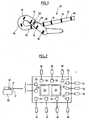
- the figure 1is an overview of the end of a left ventricular pacing lead with multiplexed electrodes.
- the figure 2globally represents the circuit of the invention with the various elements to which it is electrically connected.
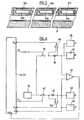
- the figure 3is a block diagram representing the main components of the circuit of the invention.
- the figure 4is a set of timing diagrams illustrating the operation of the circuit of the invention.
- the figure 5represents, in section, a detail of the probe body in an alternative embodiment of the invention.
- the figure 6is a block diagram representing the main components of the circuit of the invention, for this variant embodiment of the invention.
- the figure 1represents schematically the end of a left ventricular stimulation probe, which will be used as an example in the following description.
- This exampleis of course in no way limiting, and the invention can be applied as well to other types of intracardiac probes (for example an endocavity probe for the detection / stimulation of the right ventricle at several sites thereof). or to stimulation and / or collection probes whose electrodes are in contact with other tissues: nerves, muscles, ...
- This probe 10is of the general type described for example by the EP 0 993 840 (ELA Medical).
- the probe body 12comprises, in the vicinity of the distal end 14 intended to be introduced into the coronary venous network, a plurality of electrodes 16, for example ten in number.
- the probefurther comprises an electronic circuit 20 mounted on a rigid ring 18. This circuit is encapsulated hermetically, while remaining biocompatible with respect to surrounding tissues and body fluids. It may be incorporated in the probe body, or disposed in a cavity thereof, in the same way as the microcables passing through the probe.
- the circuit 20is shown in more detail figure 2 .
- first chip 22incorporating the electronic circuit proper (an ASIC), and a second chip 24 with a series of switches, advantageously integrated in the form of electromechanical microsystems (MEMS).
- ASICelectronic circuit proper
- MEMSelectromechanical microsystems
- the circuitcomprises two terminals 26, 28, hereinafter respectively referred to as “proximal terminal” and “distal terminal”, connected to the two conventional proximal P and distal D poles of a remote bipolar pacing generator, via a extending microcable. over the entire length of the probe body and a connector 32 plugged into the generator 30.
- the circuitalso comprises ten electrode terminals 34, each connected by a microcable to a respective electrode 16 disposed on the surface of the probe.
- the figure 3represents the circuit diagram of the circuit 22 and its associated switches 24.
- This diagramshows the proximal 26 and distal terminals 28, as well as the ten electrode terminals 34. For clarity of the drawing, these terminals have been split into two series of ten terminals in the upper and lower part of the diagram, but It should be understood that the first terminal 34 of the upper series is electrically connected to the first terminal 34 of the lower series, and so on for the other nine respective terminals of each series.
- Each electrode terminal 34is connected to the proximal terminal 26 via a respective switch 36 and a common series resistor 38. Each electrode terminal 34 is likewise connected to the distal terminal 28 via a respective switch 40 and a switch. common series resistor 42.
- the switches 36, 40are advantageously bistable components that do not require energy to maintain them in one state or the other, but only to effect a change of state.
- the switches 36are controlled by respective signals P 1 ... P 10 delivered by a first decoding circuit 44; the switches 40 are controlled in the same way by respective signals D 1 ... D 10 delivered by a second decoding circuit 46.
- the circuit 22is provided with power supply means (not shown), for example having a diode followed by a capacitor, possibly associated with a voltage regulator circuit, in order to rectify the signals received on the terminals 26. and 28 and store the corresponding energy in the capacitor.
- power supply meansfor example having a diode followed by a capacitor, possibly associated with a voltage regulator circuit, in order to rectify the signals received on the terminals 26. and 28 and store the corresponding energy in the capacitor.
- the decoding circuits 44 and 46include logic for detecting and analyzing a series of logic pulses applied to the proximal 26 and / or distal terminals 28 (P and D signals input to the circuits 44 and 46).
- the codingis for example a Manchester-type coding, a logic high level (one) being given by a sequence '10', and a logic low level (zero) being given by a sequence '01', the duration of the '1' and '0' being the same, for example 30 ⁇ s.
- the circuits 44 and 46also comprise a synchronization logic making it possible to reconstitute a clock signal from a series of received logic pulses, the half-clock period being defined by the duration separating two pulse fronts.
- the circuits 44 and 46measure the durations separating the logic levels low and high and deduce an address defining the (s) contact (s) 36 or 40 to close.
- the decoding of the signalthus makes it possible to establish a corresponding particular configuration where each electrode is either connected to the proximal terminal 26, or connected to the distal terminal 28, or electrically isolated from these two terminals.
- the proximal terminal P of the generatorwill be connected to one or more of the ten electrodes of the probe, and its distal terminal D to one or more of these ten electrodes, to allow operation in bipolar detection / stimulation. If a single terminal P or D of the generator is used, or if it has only one terminal, the generator can operate in unipolar or pseudobipolar detection / stimulation, the current loop closing through the body of the patient until metal case of the generator.
- the circuit 22is also provided with a surge arrester to protect the electronics of the circuit in the event of a defibrillation shock, the use of an electrocautery, etc.
- This surge detectoruses a comparator 48 capable of detecting in the resistor 38 a current I P greater than a given limit value, for example greater than 100 mA. If a current greater than this value is detected, then the output of the comparator 48 switches and applies to the circuit 44 a signal P 0 triggering the immediate opening of all the switches 36.
- a comparator 50measures in the resistor 42 a current I d greater than a given limit value, to apply at the circuit 46 a signal D 0 triggering the immediate opening of all the switches 40.
- the circuit 22also comprises a comparator 52, which is a fast analog circuit having a response time of less than 10 ⁇ s, for detecting between the two proximal terminals 26 and distal terminal 28 a differential voltage greater than a given threshold, for example greater than 500 mV.
- a given thresholdfor example greater than 500 mV.
- a first phasecorresponding to a period of inactivity of the device, the two proximal and distal terminals P and D of the generator are placed by the latter in a high impedance state (HiZ), as represented at 60 and 62.
- HiZhigh impedance state
- the generatorearths its proximal terminal P, as shown in 64 (duration t 1 ). This state, corresponding to a logic zero level, will then be maintained during the subsequent operations until the application of the stimulation pulse.
- the housingAfter having zero volt proximal terminal P, the housing applies on the distal terminal D a microimpulse 66 marking the beginning of the next phase (PHASE 2).
- the micro-pulse 66has, for example, an amplitude of 0.5 V and a duration of at most a few microseconds or microsecond fractions. Given its low voltage and its short duration, the energy contained in this microimpulsion is very small, in any case insufficient to present any risk for the patient - indeed, this microimpulsion is also applied to the electrode or that (s) of the electrodes, which is connected to the distal terminal 28 of the circuit 22 of the probe.
- This micro-pulseis detected by the comparator 52, as illustrated at 68.
- the time required for the comparator to detect the micro-pulse and to change its output stateis very small, typically less than one microsecond, since it is simply a matter of to control the switching of a comparator, an operation that does not require any decoding or logical processing.
- Detection of the micro-pulsecauses all of the switches 36 and 40 of the circuit to open for the duration of PHASE 2.
- the generatorproduces a coded pulse sequence 72 designating the one or more of the switches to be connected to either the proximal terminal 26 or the distal terminal 28 (the other switches being intended to remain open). Since the proximal terminal P is always zero to serve as an electrical ground, as illustrated at 70, the encoded pulse sequence 72 received at the distal terminal 28 is detected by the comparator 52 and is identical to the output of the comparator 52. to be applied as such to the decoding circuits 44, 46 (P x and D x signals).
- the next phase(PHASE 3) consists, after receiving the coded signal 72, in forcing the closure of the one or more of the switches designated by the coded pulses. Meanwhile, the generator maintains the proximal terminal (as shown at 74) grounded and places the distal terminal D (as shown at 76) in a high impedance state.
- the stimulation pulse 78can then be applied.
- the proximal terminal Premains switched to ground (as shown in 74), whereas for unipolar stimulation it is placed by the high impedance generator (as shown in 80).
- the deviceAfter applying the stimulation pulse 78, the device returns to the idle state.
- the proximal P and distal D terminalsare replaced by the high impedance generator (as shown at 82 and 84), the switches remaining in the state they previously occupied.
- the multiplexing / demultiplexing circuit 20is distributed in a plurality of physically distinct sub-circuits 20a, 20b, 20c ... disposed at right electrodes 16a, 16b, 16c, ... corresponding respectively.
- Each of these subcircuitsprovides addressing and decoding of the associated electrode, and is incorporated in the thickness of the wall of the probe body 12.
- the figure 6represents the electrical diagram of such a subcircuit. It contains the same main elements as those of the illustrated circuit figure 3 , namely a proximal terminal 26 and a distal edge 28, a decoding logic 44, 46, surge detectors 38, 48 and 42, 50 as well as a comparator 52 for decoding the initial micro-pulse and the changes of states successive logic of the control sequence.
- the sub-circuitis connected to a single electrode terminal 34, and has only two switches 36, 40: one 36 to connect the electrode terminal 34 to the proximal terminal 26, the other 40 to connect the electrode terminal 34 to the distal terminal 28.
- Each sub-circuitincorporates its own decoding integrated circuit 44, 46 which ensures the selection of the corresponding electrode by controlled opening / closing of the associated switch 36 or 40.
- Each of the subcircuitsincludes a second proximal terminal 26 'and a second distal terminal 28', electrically connected to terminals 26 and 28, respectively. These second terminals serve as output terminals P 'and D' for conducting the signals received on the proximal input terminals P and D distal to the next sub-circuit, that is to say the sub-circuit located in downstream in the distal direction. From the electrical point of view, the different sub-circuits 20a, 20b, 20c, ...
Landscapes
- Health & Medical Sciences (AREA)
- Radiology & Medical Imaging (AREA)
- Engineering & Computer Science (AREA)
- Biomedical Technology (AREA)
- Nuclear Medicine, Radiotherapy & Molecular Imaging (AREA)
- Life Sciences & Earth Sciences (AREA)
- Animal Behavior & Ethology (AREA)
- General Health & Medical Sciences (AREA)
- Public Health (AREA)
- Veterinary Medicine (AREA)
- Neurosurgery (AREA)
- Neurology (AREA)
- Electrotherapy Devices (AREA)
- Measurement And Recording Of Electrical Phenomena And Electrical Characteristics Of The Living Body (AREA)
Abstract
Description
Translated fromFrenchL'invention concerne, de façon générale, le domaine des "dispositifs médicaux actifs" tels que définis par la directive 93/42/CE du 14 juin 1993 du Conseil des communautés européennes, et notamment les "dispositifs médicaux implantables actifs" tels que définis par la directive du Conseil 90/385/CEE du 20 juin 1990.The invention relates generally to the field of "active medical devices" as defined by the Council of European Communities Directive 93/42 / EC of 14 June 1993, and in particular "active implantable medical devices" as defined by Council Directive 90/385 / EEC of 20 June 1990.
Cette définition inclut en particulier les appareils chargés de surveiller l'activité cardiaque et de générer des impulsions de stimulation, de resynchronisation, de défibrillation et/ou de cardioversion en cas de trouble du rythme détecté par l'appareil. Elle inclut aussi les appareils neurologiques, les pompes de diffusion de substances médicales, les implants cochléaires, les capteurs biologiques implantés, etc., ainsi que les dispositifs de mesure de pH ou encore d'impédance intracorporelle (telle que mesure d'impédance transpulmonaire ou d'impédance intracardiaque).This definition includes in particular the devices responsible for monitoring cardiac activity and generating pacing, resynchronization, defibrillation and / or cardioversion pulses in the event of arrhythmia detected by the device. It also includes neurological devices, medical substance delivery pumps, cochlear implants, implanted biological sensors, etc., as well as devices for measuring pH or intracorporeal impedance (such as trans-pulmonary impedance measurement or intracardiac impedance).
Pour le recueil des signaux et la délivrance d'impulsions de stimulation, ces dispositifs médicaux implantables actifs font appel à des électrodes intégrées à une sonde, elle-même reliée au générateur du dispositif.For the collection of signals and the delivery of stimulation pulses, these active implantable medical devices use electrodes integrated in a probe, itself connected to the generator of the device.
Ces électrodes sont destinées à venir en contact avec les tissus à stimuler ou ceux sur lesquels on souhaite recueillir un signal électrique : myocarde, nerf, muscle, ... Dans le cas d'un dispositif de diagnostic et de thérapie cardiaque, ces électrodes peuvent être des électrodes endocavitaires (placées dans une cavité du myocarde en contact avec la paroi de celui-ci), épicardiques (notamment pour définir un potentiel de référence, ou pour appliquer un choc), ou encore intravasculaires (la sonde est par exemple introduite dans le sinus coronaire jusqu'à un emplacement situé face à la paroi du ventricule gauche).These electrodes are intended to come into contact with the tissues to be stimulated or those on which it is desired to collect an electrical signal: myocardium, nerve, muscle, etc. In the case of a device for diagnosis and cardiac therapy, these electrodes may be endocavitary electrodes (placed in a myocardial cavity in contact with the wall thereof), epicardial (in particular to define a reference potential, or to apply a shock), or intravascular (the probe is for example introduced into the coronary sinus to a location opposite the wall of the left ventricle).
Le développement récent des appareils dits "multisite" a conduit à la multiplication du nombre d'électrodes, de manière à permettre le choix d'un ou plusieurs sites de stimulation et de détection optimisant le fonctionnement de l'appareil.The recent development of devices called "multisite" has led to the multiplication of the number of electrodes, so as to allow the choice of one or more sites of stimulation and detection optimizing the operation of the device.
Ainsi, dans le cas particulier des dispositifs de resynchronisation ventriculaire (dispositifs dits CRT,Cardiac Resynchronization Therapy), que l'on exposera ici à titre d'exemple non limitatif, il convient d'implanter au patient un appareil muni d'électrodes permettant de stimuler l'un et l'autre des ventricules. La stimulation du ventricule droit (et de l'oreillette droite) est opérée par une sonde endocavitaire classique, mais pour le ventricule gauche l'accès est plus complexe : la stimulation est généralement opérée au moyen d'une sonde introduite dans le sinus coronaire du ventricule droit puis poussée dans une veine coronaire sur l'épicarde, de façon que l'extrémité de la sonde vienne se placer face au ventricule gauche. Cette procédure est toutefois assez délicate, car le diamètre des vaisseaux coronaires se réduit avec l'avancement de la sonde, de sorte qu'il n'est pas toujours facile de trouver la position optimale lors de l'implantation. La proximité du nerf phrénique peut par ailleurs conduire à des stimulations inappropriées.Thus, in the particular case of ventricular resynchronization devices (so-called CRT devices,Cardiac Resynchronization Therapy), which will be exposed here by way of non-limiting example, it is necessary to implant the patient an apparatus provided with electrodes allowing stimulate both ventricles. Stimulation of the right ventricle (and the right atrium) is performed by a conventional endocardial lead, but for the ventricle left access is more complex: the stimulation is usually operated by means of a probe introduced into the coronary sinus of the right ventricle and then pushed into a coronary vein on the epicardium, so that the end of the probe comes to be placed facing the left ventricle. This procedure is however rather delicate, because the diameter of the coronary vessels is reduced with the advancement of the probe, so that it is not always easy to find the optimal position during implantation. The proximity of the phrenic nerve may also lead to inappropriate stimulation.
Pour pallier ces difficultés, on a développé des sondes dites multiélectrodes, pourvues par exemple de dix électrodes et dont il est possible de choisir après implantation l'électrode de stimulation la plus efficace. Cette sélection de l'électrode peut être réalisée de façon automatique par mesure des pics d'accélération endocardiaque (PEA), par mesure de bioimpédance, ou à partir tout autre capteur permettant de donner une information représentative de l'état hémodynamique du patient. Elle peut également être opérée manuellement par le praticien, au moyen d'un programmateur approprié commandant le générateur.To overcome these difficulties, so-called multielectrode probes have been developed, provided for example with ten electrodes and the most effective stimulation electrode can be chosen after implantation. This selection of the electrode can be performed automatically by measuring endocardial acceleration (PEA) peaks, by bioimpedance measurement, or from any other sensor to give information representative of the hemodynamic state of the patient. It can also be operated manually by the practitioner, by means of a suitable programmer controlling the generator.
Compte tenu du diamètre très restreint du corps de sonde, il n'est pas envisageable d'y loger autant de conducteurs que d'électrodes, ce qui conduirait à des dimensions inacceptables aussi bien pour la sonde elle-même que pour le connecteur de liaison de celle-ci au générateur implanté.Given the very small diameter of the probe body, it is not possible to accommodate as many conductors as electrodes, which would lead to unacceptable dimensions for both the probe itself as the connection connector from it to the implanted generator.
Pour ces raisons, il a été développé des systèmes de multiplexage des électrodes permettant d'interfacer la multiplicité d'électrodes avec les deux conducteurs reliés aux bornes du générateur (ces deux bornes étant désignés par la suite "distale" et "proximale", par analogie avec le positionnement des deux électrodes d'une sonde bipolaire endocavitaire simple). Dans une forme simplifiée, ces deux conducteurs peuvent être remplacés par un conducteur unique (correspondant à une sonde endocavitaire monopolaire simple), le retour du circuit étant assuré par le boîtier du générateur, via les tissus corporels du patient - on assimilera ce cas particulier à celui où la sonde comporte deux conducteurs.For these reasons, it has been developed systems of multiplexing electrodes for interfacing the multiplicity of electrodes with the two conductors connected to the terminals of the generator (these two terminals being designated hereinafter "distal" and "proximal" by analogy with the positioning of the two electrodes of a single bipolar endocavity probe). In a simplified form, these two conductors can be replaced by a single conductor (corresponding to a single monopolar endocavitary probe), the return of the circuit being provided by the generator housing, via the body tissues of the patient - this particular case will be assimilated to where the probe has two conductors.
Les
Les circuits de multiplexage/démultiplexage et les commutateurs sont de préférence situés en bout de sonde. Les commutateurs sont avantageusement des microsystèmes électromécaniques (MEMS), technologiquement intégrables sur le substrat d'une puce qui peut être incorporée dans le corps de sonde. De tels composants sont par exemple décrits dans le
Dans les techniques utilisées jusqu'à présent, notamment celle décrite par les
Cette technique présente cependant un risque. En effet, lorsque l'octet à zéro définissant le début de la séquence d'impulsions codées est appliqué au circuit, le niveau logique correspondant est également appliqué sur au moins l'une des électrodes - celle(s) qui est commutée(s) - car les commutateurs n'ont pas encore été forcés à s'ouvrir tous. Ceci crée un risque non négligeable pour le patient, car les niveaux logiques de la séquence d'impulsions sont à des niveaux de tension non négligeables, susceptibles d'induire une fibrillation incontrôlée, créant donc un risque vital pour le patient.This technique, however, presents a risk. Indeed, when the zero byte defining the start of the coded pulse sequence is applied to the circuit, the corresponding logic level is also applied to at least one of the electrodes - the one (s) being switched - because the switches have not yet been forced to open all. This creates a significant risk for the patient, because the logical levels of the pulse sequence are at significant levels of voltage, susceptible to induce uncontrolled fibrillation, thus creating a vital risk for the patient.
Pour ces raisons, la technique proposée par l'art antérieur est principalement limitée à la sélection de l'électrode optimale, ou des électrodes optimales, au moment de l'implantation, mais ne convient pas à une reprogrammation ultérieure, automatique ou manuelle, de la configuration des électrodes commutés.For these reasons, the technique proposed by the prior art is mainly limited to the selection of the optimal electrode, or optimal electrodes, at the time of implantation, but is not suitable for subsequent reprogramming, automatic or manual, of the configuration of the switched electrodes.
L'un des buts de l'invention est de proposer une solution à ce problème, en procurant un moyen rapide d'ouverture des commutateurs qui évite d'appliquer une tension excessive au coeur du patient, écartant ainsi tout risque de déclencher une fibrillation chez ce dernier.One of the aims of the invention is to propose a solution to this problem, by providing a quick means of opening the switches which avoids applying excessive tension to the patient's heart, thus avoiding any risk of triggering fibrillation in the patient. this last.
L'invention propose à cet effet un circuit de commutation contrôlée d'électrodes multiplexées du type général décrit par le
De façon caractéristique de l'invention, les moyens de commande comportent en outre des moyens de détection d'une microimpulsion dans le signal modulé reçu, cette microimpulsion précédant ladite série codée d'impulsions logiques et présentant une amplitude et une durée inférieures à l'amplitude et à la durée de chacune desdites impulsions logiques, et d'activation en réponse de tous les commutateurs en position ouverte pendant une durée au moins égale à la durée de la réception de la série codée d'impulsions logiques.In a characteristic manner of the invention, the control means also comprise means for detecting a micro-pulse in the received modulated signal, this micro-pulse preceding said coded series of logic pulses and having a magnitude and a duration less than amplitude and duration of each of said logic pulses, and activation in response of all switches in the open position for a duration at least equal to the duration of the reception of the coded series of logic pulses.
Les moyens de détection de la microimpulsion peuvent notamment comprendre un comparateur rapide présentant un temps de réponse inférieur à 10 µs.The means for detecting the micro-pulse may in particular comprise a fast comparator having a response time of less than 10 μs.
Dans une forme de réalisation particulière, le circuit de commutation contrôlée est formé d'une pluralité de sous-circuits distincts comprenant chacun une borne d'électrode respective apte à être reliée à l'une desdites électrodes de détection/stimulation de la sonde, ainsi que le(s)dit(s) commutateur(s) associé à cette borne d'électrode, et chacun de ces sous-circuits inclut des moyens de commande propres.In a particular embodiment, the controlled switching circuit is formed of a plurality of distinct subcircuits each comprising a respective electrode terminal adapted to be connected to one of said sensor detection / stimulation electrodes, and the said switch (s) associated with this electrode terminal, and each of these sub-circuits includes own control means.
L'invention a également pour objet une sonde comportant un tel circuit.The invention also relates to a probe comprising such a circuit.
Ce circuit est avantageusement disposé dans la sonde à la seconde extrémité de celle-ci, au voisinage des électrodes de détection/stimulation.This circuit is advantageously arranged in the probe at the second end thereof, in the vicinity of the detection / stimulation electrodes.
Lorsque le circuit de commutation contrôlée est un circuit réparti entre plusieurs sous-circuits, ces derniers sont avantageusement incorporés chacun au corps de sonde, ou disposés dans une cavité du corps de sonde, au droit d'une électrode correspondante et couplés au(x)dit(s) conducteur(s).When the controlled switching circuit is a circuit distributed between several sub-circuits, the latter are advantageously each incorporated in the probe body, or arranged in a cavity of the probe body, to the right of a corresponding electrode and coupled to the (x) said driver (s).
L'invention a également pour objet un générateur permettant de produire le signal tel qu'exposé ci-dessus.The invention also relates to a generator for producing the signal as described above.
Ce générateur peut avantageusement prévoir des moyens pour placer dans un état à haute impédance la borne proximale et/ou distale préalablement à la délivrance de la microimpulsion. Plus précisément, ces moyens permettent de placer dans un état à haute impédance l'une des deux bornes proximale ou distale et mettre à la masse l'autre borne, préalablement à la délivrance de la microimpulsion.This generator may advantageously provide means for placing in a high impedance state the proximal and / or distal terminal prior to delivery of the microimpulsion. More precisely, these means make it possible to place one of the two proximal or distal terminals in a high-impedance state and to ground the other terminal, prior to the delivery of the micro-pulse.
Enfin, l'invention a également pour objet le signal tel qu'exposé ci-dessus, considéré en tant que tel.Finally, the subject of the invention is also the signal as described above, considered as such.
On va maintenant décrire un exemple de mise en oeuvre du dispositif de l'invention, en référence aux dessins annexés où les mêmes références numériques désignent d'une figure à l'autre des éléments identiques ou fonctionnellement semblables.An embodiment of the device of the invention will now be described with reference to the appended drawings in which the same reference numerals designate identical or functionally similar elements from one figure to another.
La
La
La
La
La
La
On va maintenant décrire un exemple de réalisation du dispositif de l'invention.An embodiment of the device of the invention will now be described.
La
Cette sonde 10 est du type général décrit par exemple par le
Le circuit 20 est représenté plus en détail
Il comporte une première puce 22 incorporant le circuit électronique proprement dit (un ASIC), et une deuxième puce 24 avec une série de commutateurs, avantageusement intégrés sous forme de microsystèmes électromécaniques (MEMS).It comprises a
Le circuit comprend deux bornes 26, 28, ci-après respectivement désignées "borne proximale" et "borne distale", reliées aux deux pôles proximal P et distal D conventionnels d'un générateur de stimulation bipolaire 30 distant, via un microcâble s'étendant sur toute la longueur du corps de sonde et un connecteur 32 enfiché sur le générateur 30.The circuit comprises two
Le circuit comporte également dix bornes d'électrode 34, reliées chacune par un microcâble à une électrode 16 respective disposée en surface de la sonde.The circuit also comprises ten
La
On retrouve sur ce schéma les bornes proximale 26 et distale 28, ainsi que les dix bornes d'électrode 34. Pour la clarté du dessin, ces bornes ont été dédoublées en deux séries de dix bornes en partie supérieure et inférieure du schéma, mais il doit être compris que la première borne 34 de la série supérieure est électriquement reliée à la première borne 34 de la série inférieure, et ainsi de suite pour les neuf autres bornes respectives de chaque série.This diagram shows the proximal 26 and
Chaque borne d'électrode 34 est reliée à la borne proximale 26 via un commutateur respectif 36 et une résistance série commune 38. Chaque borne d'électrode 34 est également reliée, de même, à la borne distale 28 via un commutateur respectif 40 et une résistance série commune 42. Les commutateurs 36, 40 sont avantageusement des composants bistables ne nécessitant pas d'énergie pour les maintenir dans un état ou dans l'autre, mais seulement pour opérer un changement d'état.Each
Les commutateurs 36 sont commandés par des signaux respectifs P1 ... P10 délivrés par un premier circuit de décodage 44 ; les commutateurs 40 sont commandés de la même façon par des signaux respectifs D1 ... D10 délivrés par un second circuit de décodage 46.The
Outre les éléments illustrés, le circuit 22 est pourvu de moyens (non représentés) d'alimentation, par exemple comportant une diode suivie d'un condensateur, éventuellement associés à un circuit régulateur de tension, afin de redresser les signaux reçus sur les bornes 26 et 28 et en stocker l'énergie correspondante dans le condensateur.In addition to the elements illustrated, the
Les circuits de décodage 44 et 46 comportent une logique permettant de détecter et analyser une série d'impulsions logiques appliquées sur les bornes proximale 26 et/ou distale 28 (signaux P et D appliqués en entrée des circuits 44 et 46). Le codage est par exemple un codage de type Manchester, un niveau logique haut (un) étant donné par une séquence '10', et un niveau logique bas (zéro) étant donné par une séquence '01', la durée des '1' et des '0' étant la même, par exemple 30 µs. Les circuits 44 et 46 comportent également une logique de synchronisation permettant de reconstituer un signal d'horloge à partir série d'impulsions logiques reçues, la demi-période d'horloge étant définie par la durée séparant deux fronts d'impulsions. Après récupération du signal d'horloge, les circuits 44 et 46 mesurent les durées séparant les niveaux logiques bas et haut et en déduisent une adresse définissant le(s) contact(s) 36 ou 40 à fermer. Le décodage du signal permet ainsi d'établir une configuration particulière correspondante où chaque électrode est soit reliée à la borne proximale 26, soit reliée à la borne distale 28, soit isolée électriquement de ces deux bornes. De la sorte, la borne proximale P du générateur sera reliée à une ou plusieurs des dix électrodes de la sonde, et sa borne distale D à une ou plusieurs autres de ces dix électrodes, pour permettre un fonctionnement en détection/stimulation bipolaire. SI une seule borne P ou D du générateur est utilisée, ou si celui-ci ne comporte qu'une borne, le générateur pourra fonctionner en détection/stimulation unipolaire ou pseudobipolaire, la boucle de courant se fermant par le corps du patient jusqu'au boîtier métallique du générateur.The
Le circuit 22 est également pourvu d'un détecteur de surtensions afin de protéger l'électronique du circuit en cas de survenue d'un choc de défibrillation, d'utilisation d'un bistouri électrique, etc. Ce détecteur de surtensions met en oeuvre un comparateur 48 susceptible de détecter dans la résistance 38 un courant lP supérieur à une valeur limite donnée, par exemple supérieure à 100 mA. Si un courant supérieur à cette valeur est détecté, alors la sortie du comparateur 48 bascule et applique au circuit 44un signal P0 déclenchant l'ouverture immédiate de l'ensemble des commutateurs 36. De même, un comparateur 50 mesure dans la résistance 42 un courant Id supérieur à une valeur limite donnée, pour appliquer au circuit 46 un signal D0 déclenchant l'ouverture immédiate de l'ensemble des commutateurs 40.The
Le circuit 22 comporte également un comparateur 52, qui est un circuit analogique rapide présentant un temps de réponse inférieur à 10 µs, servant à détecter entre les deux bornes proximale 26 et distale 28 une tension différentielle supérieure à un seuil donné, par exemple supérieure à 500 mV. Cette situation se présente notamment, comme on l'expliquera en référence aux chronogrammes de la
On a représenté sur la
Dans une première phase (PHASE 1), correspondant à une période d'inactivité du dispositif, les deux bornes proximale et distale P et D du générateur sont placées par ce dernier dans un état à haute impédance (HiZ), comme représenté en 60 et 62.In a first phase (PHASE 1), corresponding to a period of inactivity of the device, the two proximal and distal terminals P and D of the generator are placed by the latter in a high impedance state (HiZ), as represented at 60 and 62.
Peu avant la fin de cette phase, le générateur met à la masse sa borne proximale P, comme représenté en 64 (durée t1),. Cet état, correspondant à un niveau logique zéro, sera ensuite maintenu pendant la suite des opérations jusqu'à l'application de l'impulsion de stimulation.Shortly before the end of this phase, the generator earths its proximal terminal P, as shown in 64 (duration t1 ). This state, corresponding to a logic zero level, will then be maintained during the subsequent operations until the application of the stimulation pulse.
Après avoir mis à zéro volt la borne proximale P, le boîtier applique sur la borne distale D une microimpulsion 66 marquant le début de la phase suivante (PHASE 2).After having zero volt proximal terminal P, the housing applies on the distal terminal D a
La microimpulsion 66 présente par exemple une amplitude de 0,5 V et une durée d'au plus quelques microsecondes ou fractions de microseconde. Compte tenu de sa faible tension et de sa faible durée, l'énergie contenue dans cette microimpulsion est très faible, en tout état de cause insuffisante pour présenter un quelconque risque pour le patient - en effet, cette microimpulsion est également appliquée à l'électrode, ou celle(s) des électrodes, qui est reliée à la borne distale 28 du circuit 22 de la sonde.The micro-pulse 66 has, for example, an amplitude of 0.5 V and a duration of at most a few microseconds or microsecond fractions. Given its low voltage and its short duration, the energy contained in this microimpulsion is very small, in any case insufficient to present any risk for the patient - indeed, this microimpulsion is also applied to the electrode or that (s) of the electrodes, which is connected to the
Cette microimpulsion est détectée par le comparateur 52, comme illustré en 68. Le temps nécessaire au comparateur pour détecter la microimpulsion et changer d'état en sortie est très faible, typiquement inférieur à la microseconde, dans la mesure où il s'agit simplement de commander le basculement d'un comparateur, opération qui ne nécessite aucun décodage ou traitement logique quelconque.This micro-pulse is detected by the
La détection de la microimpulsion provoque l'ouverture de la totalité des commutateurs 36 et 40 du circuit, et ce pendant toute la durée de la PHASE 2. Pendant cette phase, le générateur produit une séquence d'impulsions codée 72 désignant celui ou ceux des commutateurs qui devra être relié(s) soit à la borne proximale 26 soit à la borne distale 28 (les autres commutateurs étant destinés à rester ouverts). Dans la mesure où la borne proximale P est toujours à zéro pour servir de masse électrique, comme illustré en 70, la série d'impulsions codée 72 reçue sur la borne distale 28 est détectée par le comparateur 52 et se retrouve identiquement en sortie de celui-ci, pour être appliquée telle quelle aux circuits de décodage 44, 46 (signaux Px et Dx).Detection of the micro-pulse causes all of the
La phase suivante (PHASE 3) consiste, après réception du signal codé 72, à forcer à la fermeture celui ou ceux des commutateurs désignés par les impulsions codées. Pendant ce temps, le générateur maintient à la masse la borne proximale (comme représenté en 74), et place dans un état à haute impédance la borne distale D (comme représenté en 76).The next phase (PHASE 3) consists, after receiving the coded
L'impulsion de stimulation 78 peut alors être appliquée. Dans le cas d'une stimulation bipolaire la borne proximale P reste commutée à la masse (comme représenté en 74), tandis que pour une stimulation unipolaire elle est placée par le générateur en haute impédance (comme représenté en 80).The
Après application de l'impulsion de stimulation 78, le dispositif retourne à l'état d'inactivité. Les bornes proximale P et distale D sont replacées par le générateur en haute impédance (comme représenté en 82 et 84), les commutateurs restant dans l'état qu'ils occupaient précédemment.After applying the
On a représenté sur les
Dans cette variante, le circuit de multiplexage/démultiplexage 20 est réparti en une pluralité de sous-circuits 20a, 20b, 20c, ... physiquement distincts, disposés au droit des électrodes 16a, 16b, 16c, ... qui leur correspondent respectivement. Chacun de ces sous-circuits assure l'adressage et le décodage de l'électrode qui lui est associée, et est incorporé dans l'épaisseur de la paroi du corps de sonde 12.In this variant, the multiplexing /
La
Dans cette variante, le sous-circuit est relié à une seule borne d'électrode 34, et ne comporte que deux commutateurs 36, 40 : l'un 36 pour relier la borne d'électrode 34 à la borne proximale 26, l'autre 40 pour relier la borne d'électrode 34 à la borne distale 28. Chaque sous-circuit intègre son propre circuit intégré de décodage 44, 46 qui assure la sélection de l'électrode correspondante par ouverture/fermeture contrôlée du commutateur 36 ou 40 associé.In this variant, the sub-circuit is connected to a
Chacun des sous-circuits comporte une deuxième borne proximale 26' et une deuxième borne distale 28', électriquement reliées aux bornes 26 et 28, respectivement. Ces deuxièmes bornes font office de bornes de sortie P' et D' pour conduire les signaux reçus sur les bornes d'entrée proximale P et distale D vers le sous-circuit suivant, c'est-à-dire le sous-circuit situé en aval dans la direction distale. Du point de vue électrique, les différents sous-circuits 20a, 20b, 20c, ... sont chacun couplés aux microcâbles reliés au pôles distal et proximal du générateur, et cette configuration permet en particulier d'éviter un foisonnement de microcâbles à partir du circuit de décodage, come cela serait le cas lorsque ce circuit est commun à plusieurs électrodes, comme dans le cas de la
Claims (6)
- Circuit (20) for controlled switching of multiplexed electrodes, for an active implantable medical device comprising a generator (30) and a probe (10) which is provided with multiplexed detection/stimulation electrodes (16) and is linked to this generator,
this circuit (20) comprising:- at least one proximal terminal (26) and/or distal terminal (28), able to be coupled to the generator,- a plurality of electrode terminals (34), able to be respectively coupled to the said detection/stimulation electrodes of the probe,- a plurality of switches (36, 40), able to take either a closed position in which a corresponding electrode terminal (34) is linked to the proximal terminal (26) or to the distal terminal (28), or an open position where this electrode is isolated from the proximal terminal and from the distal terminal, and- control means, comprising means (44, 46, 52) of:circuitcharacterized in that the control means furthermore comprise means of:• reception on the proximal and/or distal terminal of a modulated signal delivered by the generator and comprising a coded series of logic pulses (72), and• decoding of this modulated signal so as to actuate the switches according to a corresponding particular configuration, defined by this modulated signal, of closed or open positions,• detection of a micropulse (66) in the modulated signal received, this micropulse preceding the said coded series of logic pulses (72) and exhibiting an amplitude and a duration that are smaller than the amplitude and the duration of each of the said logic pulses, and• activation in response of all the switches in the open position for a duration (PHASE 2) at least equal to the duration of reception of the coded series of logic pulses. - Circuit of Claim 1, in which the means for detecting a micropulse comprise a fast comparator (48; 50) exhibiting a response time of less than 10 µs.
- Circuit of Claim 1, in which the said controlled switching circuit is formed of a plurality of distinct sub-circuits (20a, 20b, 20c,...) each comprising a respective electrode terminal (34) able to be linked to one of the said detection/stimulation electrodes (16a, 16b, 16c,...) of the probe, as well as the said switch(es) (36, 40) associated with this electrode terminal (34), and in which each of these sub-circuits (20a, 20b, 20c,...) includes inherent control means (44, 46, 52).
- Probe (10) provided with multiplexed detection/stimulation electrodes, for an active implantable medical device comprising a generator (30) and the said probe linked to this generator,
this probe (10) comprising:- an elongate probe body (12), including at least one conductor,- at a first end of the probe body, a connector (32) linked to the said conductor(s) and able to be linked to at least one corresponding proximal and/or distal terminal of the generator,- at a second, opposite, end of the probe body, a plurality of multiplexed detection/stimulation electrodes (16), and- a controlled switching circuit (20) according to one of Claims 1 to 3, able to selectively couple or decouple each of the electrodes with the said (with one of the said) conductor(s). - Detection/stimulation probe of Claim 4, where the said controlled switching circuit is disposed in the probe at the second end of the latter, in the vicinity of the detection/stimulation electrodes.
- Detection/stimulation probe of Claim 4, in which the said controlled switching circuit is a circuit according to Claim 3, and in which the sub-circuits (20a, 20b, 20c,...) are each incorporated into the probe body (12), or disposed in a cavity of the probe body (12), square with a corresponding electrode (16a, 16b, 16c,...) and coupled to the said conductor(s) (D, P).
Applications Claiming Priority (1)
| Application Number | Priority Date | Filing Date | Title |
|---|---|---|---|
| FR0611478AFR2910818A1 (en) | 2006-12-28 | 2006-12-28 | MULTIPLEXED ELECTRODE CONTROLLED SWITCHING CIRCUIT FOR ACTIVE ACTIVE IMPLANTABLE DISPOSITION |
Publications (2)
| Publication Number | Publication Date |
|---|---|
| EP1938861A1 EP1938861A1 (en) | 2008-07-02 |
| EP1938861B1true EP1938861B1 (en) | 2011-02-16 |
Family
ID=38326857
Family Applications (1)
| Application Number | Title | Priority Date | Filing Date |
|---|---|---|---|
| EP07291516AActiveEP1938861B1 (en) | 2006-12-28 | 2007-12-13 | Controlled switching circuit of multiplexed electrodes, for an active implantable medical device |
Country Status (6)
| Country | Link |
|---|---|
| US (1) | US8255048B2 (en) |
| EP (1) | EP1938861B1 (en) |
| JP (1) | JP5224579B2 (en) |
| AT (1) | ATE498424T1 (en) |
| DE (1) | DE602007012510D1 (en) |
| FR (1) | FR2910818A1 (en) |
Cited By (6)
| Publication number | Priority date | Publication date | Assignee | Title |
|---|---|---|---|---|
| US7974705B2 (en) | 2008-11-13 | 2011-07-05 | Proteus Biomedical, Inc. | Multiplexed multi-electrode neurostimulation devices |
| US7983751B2 (en) | 2005-08-12 | 2011-07-19 | Proteus Biomedical, Inc. | Measuring conduction velocity using one or more satellite devices |
| US8036743B2 (en) | 2005-03-31 | 2011-10-11 | Proteus Biomedical, Inc. | Automated optimization of multi-electrode pacing for cardiac resynchronization |
| US8644919B2 (en) | 2008-11-13 | 2014-02-04 | Proteus Digital Health, Inc. | Shielded stimulation and sensing system and method |
| US8712549B2 (en) | 2002-12-11 | 2014-04-29 | Proteus Digital Health, Inc. | Method and system for monitoring and treating hemodynamic parameters |
| US8786049B2 (en) | 2009-07-23 | 2014-07-22 | Proteus Digital Health, Inc. | Solid-state thin-film capacitor |
Families Citing this family (31)
| Publication number | Priority date | Publication date | Assignee | Title |
|---|---|---|---|---|
| US8364284B2 (en) | 2008-09-15 | 2013-01-29 | Boston Scientific Neuromodulation Corporation | Implantable electric stimulation system and methods of making and using |
| US8473069B2 (en) | 2008-02-28 | 2013-06-25 | Proteus Digital Health, Inc. | Integrated circuit implementation and fault control system, device, and method |
| US20090287266A1 (en)* | 2008-05-13 | 2009-11-19 | Mark Zdeblick | High-voltage tolerant multiplex multi-electrode stimulation systems and methods for using the same |
| US8255057B2 (en) | 2009-01-29 | 2012-08-28 | Nevro Corporation | Systems and methods for producing asynchronous neural responses to treat pain and/or other patient conditions |
| US9327121B2 (en) | 2011-09-08 | 2016-05-03 | Nevro Corporation | Selective high frequency spinal cord modulation for inhibiting pain, including cephalic and/or total body pain with reduced side effects, and associated systems and methods |
| ES2942684T3 (en) | 2009-04-22 | 2023-06-05 | Nevro Corp | Spinal cord modulation systems to induce paresthetic and anesthetic effects |
| US8718770B2 (en) | 2010-10-21 | 2014-05-06 | Medtronic, Inc. | Capture threshold measurement for selection of pacing vector |
| EP2455131B1 (en) | 2010-11-19 | 2013-01-23 | Sorin CRM SAS | Probe for stimulating a left cavity of the heart which can be implanted in the coronary network |
| EP2465425B1 (en) | 2010-12-14 | 2013-01-23 | Sorin CRM SAS | Lead for an active implantable medical device, comprising a microchip, in particular for multiplexing |
| EP2495013B1 (en) | 2011-03-03 | 2013-07-24 | Sorin CRM SAS | Assembly for searching for an optimal configuration of a bi-, tri- or multi-ventricular cardiac resynchronisation implant |
| US8355784B2 (en) | 2011-05-13 | 2013-01-15 | Medtronic, Inc. | Dynamic representation of multipolar leads in a programmer interface |
| EP2559453B1 (en) | 2011-08-18 | 2014-07-16 | Sorin CRM SAS | Lead implantable in the coronary vessels for multi-zone stimulation of a left heart chamber |
| EP2572751B1 (en) | 2011-09-21 | 2014-10-29 | Sorin CRM SAS | Probe for stimulation in an extended region of a cardiac chamber, which can be implanted by wire guidance in the deep coronary network |
| EP2574368B1 (en) | 2011-09-30 | 2014-12-24 | Sorin CRM SAS | Multizone epicardial stimulation probe |
| EP2581108B1 (en) | 2011-10-13 | 2013-10-23 | Sorin CRM SAS | Module for controlled switching of a multielectrode probe for an active implantable medical device |
| FR2991882A1 (en) | 2012-06-13 | 2013-12-20 | Sorin Crm Sas | ELECTRODE STRUCTURE FOR A MULTIPOLAR DETECTION / STIMULATION MICROSONDE INTENDED TO BE IMPLANTED INTO A CARDIAC OR CEREBRAL VESSEL |
| US9895539B1 (en) | 2013-06-10 | 2018-02-20 | Nevro Corp. | Methods and systems for disease treatment using electrical stimulation |
| US10149978B1 (en) | 2013-11-07 | 2018-12-11 | Nevro Corp. | Spinal cord modulation for inhibiting pain via short pulse width waveforms, and associated systems and methods |
| JP2017501800A (en) | 2013-12-18 | 2017-01-19 | カーディアック ペースメイカーズ, インコーポレイテッド | Method for selecting a vector for delivering electrical stimulation to a patient |
| JP6470291B2 (en) | 2013-12-18 | 2019-02-13 | カーディアック ペースメイカーズ, インコーポレイテッド | System and method for facilitating selection of one or more vectors in a medical device |
| US9750942B2 (en) | 2013-12-18 | 2017-09-05 | Cardiac Pacemakers, Inc. | Systems and methods for determining parameters for each of a plurality of vectors |
| CA2880636C (en)* | 2014-01-31 | 2022-11-22 | James Andrew Leskosek | Medical device for heart stimulations |
| EP3075411B1 (en) | 2015-04-03 | 2017-10-25 | Sorin CRM SAS | Multi-electrode probe with multiplexed control, in particular for cardiac stimulation, and associated connection method |
| US11318310B1 (en) | 2015-10-26 | 2022-05-03 | Nevro Corp. | Neuromodulation for altering autonomic functions, and associated systems and methods |
| EP3389775B1 (en) | 2015-12-17 | 2019-09-25 | Cardiac Pacemakers, Inc. | Conducted communication in a medical device system |
| CN109310865B (en) | 2016-01-25 | 2022-09-13 | 内弗洛公司 | Electrostimulation treatment of congestive heart failure, and associated systems and methods |
| US10912938B2 (en) | 2016-05-19 | 2021-02-09 | Sorin Crm Sas | Dual multipolar lead implantable in the coronary venous network |
| US11590352B2 (en) | 2019-01-29 | 2023-02-28 | Nevro Corp. | Ramped therapeutic signals for modulating inhibitory interneurons, and associated systems and methods |
| US11717675B2 (en) | 2019-08-02 | 2023-08-08 | Biosense Webster (Israel) Ltd. | Patient-safe electromechanical switching for pacing with a catheter having multiple electrodes |
| US20240000441A1 (en)* | 2020-11-18 | 2024-01-04 | Trustees Of Tufts College | Spatially-Selective Sampling of Gut Microbiome |
| TW202241542A (en)* | 2021-02-03 | 2022-11-01 | 澳大利亞商希爾艾德生命救援私人有限公司 | Automated external defibrillators with multiple, multifunctional electrode pairs |
Family Cites Families (12)
| Publication number | Priority date | Publication date | Assignee | Title |
|---|---|---|---|---|
| US4793353A (en)* | 1981-06-30 | 1988-12-27 | Borkan William N | Non-invasive multiprogrammable tissue stimulator and method |
| US4532930A (en)* | 1983-04-11 | 1985-08-06 | Commonwealth Of Australia, Dept. Of Science & Technology | Cochlear implant system for an auditory prosthesis |
| SE9202521D0 (en)* | 1992-09-02 | 1992-09-02 | Siemens Elema Ab | DEVICE FOR STIMULATION OF LIVING WEAVEN |
| US5649970A (en)* | 1995-08-18 | 1997-07-22 | Loeb; Gerald E. | Edge-effect electrodes for inducing spatially controlled distributions of electrical potentials in volume conductive media |
| WO1997022313A1 (en)* | 1995-12-19 | 1997-06-26 | Cochlear Limited | Cochlear implant system with soft turn on electrodes |
| US6704602B2 (en)* | 1998-07-02 | 2004-03-09 | Medtronic, Inc. | Implanted medical device/external medical instrument communication utilizing surface electrodes |
| FR2784300B1 (en) | 1998-10-13 | 2000-12-08 | Ela Medical Sa | IMPLANTABLE LEFT VENTRICLE STIMULATION PROBE IN THE CORONARY VENOUS NETWORK FOR ACTIVE IMPLANTABLE MEDICAL DEVICE, IN PARTICULAR "MULTI-SITE" STIMULATOR |
| DE19930265A1 (en) | 1999-06-25 | 2000-12-28 | Biotronik Mess & Therapieg | Electrode arrangement |
| US6643546B2 (en)* | 2001-02-13 | 2003-11-04 | Quetzal Biomedical, Inc. | Multi-electrode apparatus and method for treatment of congestive heart failure |
| US20030149456A1 (en) | 2002-02-01 | 2003-08-07 | Rottenberg William B. | Multi-electrode cardiac lead adapter with multiplexer |
| US7474923B2 (en) | 2003-04-29 | 2009-01-06 | Medtronic, Inc. | Micro electromechanical switches and medical devices incorporating same |
| WO2006029090A2 (en) | 2004-09-02 | 2006-03-16 | Proteus Biomedical, Inc. | Methods and apparatus for tissue activation and monitoring |
- 2006
- 2006-12-28FRFR0611478Apatent/FR2910818A1/enactivePending
- 2007
- 2007-12-13DEDE602007012510Tpatent/DE602007012510D1/enactiveActive
- 2007-12-13ATAT07291516Tpatent/ATE498424T1/ennot_activeIP Right Cessation
- 2007-12-13EPEP07291516Apatent/EP1938861B1/enactiveActive
- 2007-12-27USUS11/965,432patent/US8255048B2/enactiveActive
- 2007-12-27JPJP2007338387Apatent/JP5224579B2/enactiveActive
Cited By (7)
| Publication number | Priority date | Publication date | Assignee | Title |
|---|---|---|---|---|
| US8712549B2 (en) | 2002-12-11 | 2014-04-29 | Proteus Digital Health, Inc. | Method and system for monitoring and treating hemodynamic parameters |
| US8036743B2 (en) | 2005-03-31 | 2011-10-11 | Proteus Biomedical, Inc. | Automated optimization of multi-electrode pacing for cardiac resynchronization |
| US7983751B2 (en) | 2005-08-12 | 2011-07-19 | Proteus Biomedical, Inc. | Measuring conduction velocity using one or more satellite devices |
| US7974705B2 (en) | 2008-11-13 | 2011-07-05 | Proteus Biomedical, Inc. | Multiplexed multi-electrode neurostimulation devices |
| US8644919B2 (en) | 2008-11-13 | 2014-02-04 | Proteus Digital Health, Inc. | Shielded stimulation and sensing system and method |
| US8738154B2 (en) | 2008-11-13 | 2014-05-27 | Proteus Digital Health, Inc. | Multiplexed multi-electrode neurostimulation devices |
| US8786049B2 (en) | 2009-07-23 | 2014-07-22 | Proteus Digital Health, Inc. | Solid-state thin-film capacitor |
Also Published As
| Publication number | Publication date |
|---|---|
| JP5224579B2 (en) | 2013-07-03 |
| ATE498424T1 (en) | 2011-03-15 |
| EP1938861A1 (en) | 2008-07-02 |
| JP2008272444A (en) | 2008-11-13 |
| DE602007012510D1 (en) | 2011-03-31 |
| FR2910818A1 (en) | 2008-07-04 |
| US8255048B2 (en) | 2012-08-28 |
| US20080177343A1 (en) | 2008-07-24 |
Similar Documents
| Publication | Publication Date | Title |
|---|---|---|
| EP1938861B1 (en) | Controlled switching circuit of multiplexed electrodes, for an active implantable medical device | |
| EP2082684B1 (en) | Active implantable medical device comprising bi-directional communication means between a generator and sensors or actuators located on the end of the probe | |
| EP1438985B1 (en) | Implantable medical device e.g. a pacemaker with means for determining the presence and the type of the associated probe | |
| FR2602146A1 (en) | STIMULATING PULSE GENERATING CIRCUIT FOR CARDIAC STIMULATOR | |
| EP2206532B1 (en) | Implantable medical heart device comprising means for detecting intense static magnetic fields and commuting to safety mode during MRI tests | |
| EP2189182B1 (en) | Implantable active medical device comprising means for atrial capture testing | |
| EP2959828B1 (en) | Hybrid assembly forming an active implantable medical device | |
| EP2926863B1 (en) | Use of an implantable cardiac generator for myocardial stimulation, defibrillation and/or resynchronisation as a vagus nerve stimulation (VNS) generator | |
| EP3075411B1 (en) | Multi-electrode probe with multiplexed control, in particular for cardiac stimulation, and associated connection method | |
| EP3187223A1 (en) | Active medical device for electric nerve stimulation, with automatic control of load compensation | |
| EP1216723B1 (en) | Device for measuring the complex impedance of a probe of an active implantable medical device, in particular of a pacemaker, defibrillator and/or cardioverter | |
| EP2495013A1 (en) | Assembly for searching for an optimal configuration of a bi-, tri- or multi-ventricular cardiac resynchronisation implant | |
| EP2803385B1 (en) | Implantable heart re-timer with biventricular stimulation and detection of losses of capture and anode stimulations | |
| EP3069755B1 (en) | Active implantable medical device comprising a connector-free capsule, permanently connected to a microprobe | |
| EP1618923B1 (en) | Implantierbarer Herzschrittmacher mit automatischer Detektion des Installieren einer Sonde und der Implantation des Gehäuses | |
| EP2581108B1 (en) | Module for controlled switching of a multielectrode probe for an active implantable medical device | |
| EP1433497B1 (en) | Active implantable medical device with detection of cardiac, in particular atrial, evoked potentials | |
| EP1543864B1 (en) | Multisite implantable active medical device comprising a resynchronisation mode of the ventricles | |
| EP2332462B1 (en) | Single-chamber implantable cardioverter/defibrillator with detection of atrial activity via the single-body probe | |
| EP3042693B1 (en) | Active implantable medical device, such as an autonomous capsule, with dynamic optimisation of the energy of stimulation pulses | |
| EP3023122B1 (en) | Active implantable medical device for co-application of cardiac and peripheral therapies, provided with means for detection and automatic coupling of probes | |
| EP3042692A1 (en) | Implantable medical device for cardiac and peripheral therapy with means for allowing or inhibiting therapy based on sensed signals | |
| EP1118349B1 (en) | One-piece probe for medical active device as implantable defibrillator/cardioverter | |
| FR2558732A1 (en) | Implantable cardiac stimulator | |
| EP3429680A1 (en) | Active implantable medical device for combined treatment of cardiac rhythm and of respiratory rhythm |
Legal Events
| Date | Code | Title | Description |
|---|---|---|---|
| PUAI | Public reference made under article 153(3) epc to a published international application that has entered the european phase | Free format text:ORIGINAL CODE: 0009012 | |
| AK | Designated contracting states | Kind code of ref document:A1 Designated state(s):AT BE BG CH CY CZ DE DK EE ES FI FR GB GR HU IE IS IT LI LT LU LV MC MT NL PL PT RO SE SI SK TR | |
| AX | Request for extension of the european patent | Extension state:AL BA HR MK RS | |
| 17P | Request for examination filed | Effective date:20081125 | |
| 17Q | First examination report despatched | Effective date:20090113 | |
| AKX | Designation fees paid | Designated state(s):AT BE BG CH CY CZ DE DK EE ES FI FR GB GR HU IE IS IT LI LT LU LV MC MT NL PL PT RO SE SI SK TR | |
| GRAP | Despatch of communication of intention to grant a patent | Free format text:ORIGINAL CODE: EPIDOSNIGR1 | |
| GRAS | Grant fee paid | Free format text:ORIGINAL CODE: EPIDOSNIGR3 | |
| GRAA | (expected) grant | Free format text:ORIGINAL CODE: 0009210 | |
| AK | Designated contracting states | Kind code of ref document:B1 Designated state(s):AT BE BG CH CY CZ DE DK EE ES FI FR GB GR HU IE IS IT LI LT LU LV MC MT NL PL PT RO SE SI SK TR | |
| REG | Reference to a national code | Ref country code:GB Ref legal event code:FG4D Free format text:NOT ENGLISH | |
| REG | Reference to a national code | Ref country code:CH Ref legal event code:EP | |
| REG | Reference to a national code | Ref country code:IE Ref legal event code:FG4D Free format text:LANGUAGE OF EP DOCUMENT: FRENCH | |
| REF | Corresponds to: | Ref document number:602007012510 Country of ref document:DE Date of ref document:20110331 Kind code of ref document:P | |
| REG | Reference to a national code | Ref country code:DE Ref legal event code:R096 Ref document number:602007012510 Country of ref document:DE Effective date:20110331 | |
| REG | Reference to a national code | Ref country code:SE Ref legal event code:TRGR | |
| REG | Reference to a national code | Ref country code:NL Ref legal event code:VDEP Effective date:20110216 | |
| LTIE | Lt: invalidation of european patent or patent extension | Effective date:20110216 | |
| PG25 | Lapsed in a contracting state [announced via postgrant information from national office to epo] | Ref country code:LT Free format text:LAPSE BECAUSE OF FAILURE TO SUBMIT A TRANSLATION OF THE DESCRIPTION OR TO PAY THE FEE WITHIN THE PRESCRIBED TIME-LIMIT Effective date:20110216 Ref country code:ES Free format text:LAPSE BECAUSE OF FAILURE TO SUBMIT A TRANSLATION OF THE DESCRIPTION OR TO PAY THE FEE WITHIN THE PRESCRIBED TIME-LIMIT Effective date:20110527 Ref country code:PT Free format text:LAPSE BECAUSE OF FAILURE TO SUBMIT A TRANSLATION OF THE DESCRIPTION OR TO PAY THE FEE WITHIN THE PRESCRIBED TIME-LIMIT Effective date:20110616 Ref country code:GR Free format text:LAPSE BECAUSE OF FAILURE TO SUBMIT A TRANSLATION OF THE DESCRIPTION OR TO PAY THE FEE WITHIN THE PRESCRIBED TIME-LIMIT Effective date:20110517 Ref country code:LV Free format text:LAPSE BECAUSE OF FAILURE TO SUBMIT A TRANSLATION OF THE DESCRIPTION OR TO PAY THE FEE WITHIN THE PRESCRIBED TIME-LIMIT Effective date:20110216 | |
| PG25 | Lapsed in a contracting state [announced via postgrant information from national office to epo] | Ref country code:CY Free format text:LAPSE BECAUSE OF FAILURE TO SUBMIT A TRANSLATION OF THE DESCRIPTION OR TO PAY THE FEE WITHIN THE PRESCRIBED TIME-LIMIT Effective date:20110216 Ref country code:SI Free format text:LAPSE BECAUSE OF FAILURE TO SUBMIT A TRANSLATION OF THE DESCRIPTION OR TO PAY THE FEE WITHIN THE PRESCRIBED TIME-LIMIT Effective date:20110216 Ref country code:PL Free format text:LAPSE BECAUSE OF FAILURE TO SUBMIT A TRANSLATION OF THE DESCRIPTION OR TO PAY THE FEE WITHIN THE PRESCRIBED TIME-LIMIT Effective date:20110216 Ref country code:AT Free format text:LAPSE BECAUSE OF FAILURE TO SUBMIT A TRANSLATION OF THE DESCRIPTION OR TO PAY THE FEE WITHIN THE PRESCRIBED TIME-LIMIT Effective date:20110216 Ref country code:FI Free format text:LAPSE BECAUSE OF FAILURE TO SUBMIT A TRANSLATION OF THE DESCRIPTION OR TO PAY THE FEE WITHIN THE PRESCRIBED TIME-LIMIT Effective date:20110216 Ref country code:BG Free format text:LAPSE BECAUSE OF FAILURE TO SUBMIT A TRANSLATION OF THE DESCRIPTION OR TO PAY THE FEE WITHIN THE PRESCRIBED TIME-LIMIT Effective date:20110516 Ref country code:NL Free format text:LAPSE BECAUSE OF FAILURE TO SUBMIT A TRANSLATION OF THE DESCRIPTION OR TO PAY THE FEE WITHIN THE PRESCRIBED TIME-LIMIT Effective date:20110216 | |
| PG25 | Lapsed in a contracting state [announced via postgrant information from national office to epo] | Ref country code:DK Free format text:LAPSE BECAUSE OF FAILURE TO SUBMIT A TRANSLATION OF THE DESCRIPTION OR TO PAY THE FEE WITHIN THE PRESCRIBED TIME-LIMIT Effective date:20110216 Ref country code:EE Free format text:LAPSE BECAUSE OF FAILURE TO SUBMIT A TRANSLATION OF THE DESCRIPTION OR TO PAY THE FEE WITHIN THE PRESCRIBED TIME-LIMIT Effective date:20110216 | |
| PG25 | Lapsed in a contracting state [announced via postgrant information from national office to epo] | Ref country code:CZ Free format text:LAPSE BECAUSE OF FAILURE TO SUBMIT A TRANSLATION OF THE DESCRIPTION OR TO PAY THE FEE WITHIN THE PRESCRIBED TIME-LIMIT Effective date:20110216 Ref country code:RO Free format text:LAPSE BECAUSE OF FAILURE TO SUBMIT A TRANSLATION OF THE DESCRIPTION OR TO PAY THE FEE WITHIN THE PRESCRIBED TIME-LIMIT Effective date:20110216 Ref country code:SK Free format text:LAPSE BECAUSE OF FAILURE TO SUBMIT A TRANSLATION OF THE DESCRIPTION OR TO PAY THE FEE WITHIN THE PRESCRIBED TIME-LIMIT Effective date:20110216 | |
| PLBE | No opposition filed within time limit | Free format text:ORIGINAL CODE: 0009261 | |
| STAA | Information on the status of an ep patent application or granted ep patent | Free format text:STATUS: NO OPPOSITION FILED WITHIN TIME LIMIT | |
| 26N | No opposition filed | Effective date:20111117 | |
| REG | Reference to a national code | Ref country code:DE Ref legal event code:R097 Ref document number:602007012510 Country of ref document:DE Effective date:20111117 | |
| BERE | Be: lapsed | Owner name:ELA MEDICAL Effective date:20111231 | |
| PG25 | Lapsed in a contracting state [announced via postgrant information from national office to epo] | Ref country code:MC Free format text:LAPSE BECAUSE OF NON-PAYMENT OF DUE FEES Effective date:20111231 | |
| REG | Reference to a national code | Ref country code:CH Ref legal event code:PL | |
| PG25 | Lapsed in a contracting state [announced via postgrant information from national office to epo] | Ref country code:CH Free format text:LAPSE BECAUSE OF NON-PAYMENT OF DUE FEES Effective date:20111231 Ref country code:LI Free format text:LAPSE BECAUSE OF NON-PAYMENT OF DUE FEES Effective date:20111231 Ref country code:BE Free format text:LAPSE BECAUSE OF NON-PAYMENT OF DUE FEES Effective date:20111231 | |
| PGFP | Annual fee paid to national office [announced via postgrant information from national office to epo] | Ref country code:IE Payment date:20121211 Year of fee payment:6 | |
| PG25 | Lapsed in a contracting state [announced via postgrant information from national office to epo] | Ref country code:MT Free format text:LAPSE BECAUSE OF FAILURE TO SUBMIT A TRANSLATION OF THE DESCRIPTION OR TO PAY THE FEE WITHIN THE PRESCRIBED TIME-LIMIT Effective date:20110216 | |
| PGFP | Annual fee paid to national office [announced via postgrant information from national office to epo] | Ref country code:SE Payment date:20121217 Year of fee payment:6 | |
| PG25 | Lapsed in a contracting state [announced via postgrant information from national office to epo] | Ref country code:LU Free format text:LAPSE BECAUSE OF NON-PAYMENT OF DUE FEES Effective date:20111213 | |
| PG25 | Lapsed in a contracting state [announced via postgrant information from national office to epo] | Ref country code:IS Free format text:LAPSE BECAUSE OF FAILURE TO SUBMIT A TRANSLATION OF THE DESCRIPTION OR TO PAY THE FEE WITHIN THE PRESCRIBED TIME-LIMIT Effective date:20110216 | |
| PG25 | Lapsed in a contracting state [announced via postgrant information from national office to epo] | Ref country code:TR Free format text:LAPSE BECAUSE OF FAILURE TO SUBMIT A TRANSLATION OF THE DESCRIPTION OR TO PAY THE FEE WITHIN THE PRESCRIBED TIME-LIMIT Effective date:20110216 | |
| PG25 | Lapsed in a contracting state [announced via postgrant information from national office to epo] | Ref country code:HU Free format text:LAPSE BECAUSE OF FAILURE TO SUBMIT A TRANSLATION OF THE DESCRIPTION OR TO PAY THE FEE WITHIN THE PRESCRIBED TIME-LIMIT Effective date:20110216 | |
| REG | Reference to a national code | Ref country code:SE Ref legal event code:EUG | |
| PG25 | Lapsed in a contracting state [announced via postgrant information from national office to epo] | Ref country code:SE Free format text:LAPSE BECAUSE OF NON-PAYMENT OF DUE FEES Effective date:20131214 | |
| REG | Reference to a national code | Ref country code:IE Ref legal event code:MM4A | |
| PG25 | Lapsed in a contracting state [announced via postgrant information from national office to epo] | Ref country code:IE Free format text:LAPSE BECAUSE OF NON-PAYMENT OF DUE FEES Effective date:20131213 | |
| REG | Reference to a national code | Ref country code:FR Ref legal event code:PLFP Year of fee payment:9 | |
| REG | Reference to a national code | Ref country code:FR Ref legal event code:PLFP Year of fee payment:10 | |
| REG | Reference to a national code | Ref country code:FR Ref legal event code:PLFP Year of fee payment:11 | |
| P01 | Opt-out of the competence of the unified patent court (upc) registered | Effective date:20230714 | |
| PGFP | Annual fee paid to national office [announced via postgrant information from national office to epo] | Ref country code:DE Payment date:20241211 Year of fee payment:18 | |
| PGFP | Annual fee paid to national office [announced via postgrant information from national office to epo] | Ref country code:GB Payment date:20241219 Year of fee payment:18 | |
| PGFP | Annual fee paid to national office [announced via postgrant information from national office to epo] | Ref country code:FR Payment date:20241224 Year of fee payment:18 | |
| PGFP | Annual fee paid to national office [announced via postgrant information from national office to epo] | Ref country code:IT Payment date:20241213 Year of fee payment:18 |