EP1938858A1 - Non-metallic guide wire - Google Patents
Non-metallic guide wireDownload PDFInfo
- Publication number
- EP1938858A1 EP1938858A1EP07023141AEP07023141AEP1938858A1EP 1938858 A1EP1938858 A1EP 1938858A1EP 07023141 AEP07023141 AEP 07023141AEP 07023141 AEP07023141 AEP 07023141AEP 1938858 A1EP1938858 A1EP 1938858A1
- Authority
- EP
- European Patent Office
- Prior art keywords
- guide wire
- core wire
- wire
- segment
- guide
- Prior art date
- Legal status (The legal status is an assumption and is not a legal conclusion. Google has not performed a legal analysis and makes no representation as to the accuracy of the status listed.)
- Granted
Links
- 239000000463materialSubstances0.000claimsabstractdescription38
- 238000000576coating methodMethods0.000claimsabstractdescription20
- 239000000835fiberSubstances0.000claimsabstractdescription10
- 229920000914Metallic fiberPolymers0.000claimsabstract4
- 239000011248coating agentSubstances0.000claimsdescription13
- 239000004696Poly ether ether ketoneSubstances0.000claimsdescription11
- 229920002530polyetherether ketonePolymers0.000claimsdescription11
- 239000011230binding agentSubstances0.000claimsdescription8
- 229920000049Carbon (fiber)Polymers0.000claimsdescription7
- 239000004917carbon fiberSubstances0.000claimsdescription7
- 229920005989resinPolymers0.000claimsdescription7
- 239000011347resinSubstances0.000claimsdescription7
- 239000004697PolyetherimideSubstances0.000claimsdescription6
- 229920001601polyetherimidePolymers0.000claimsdescription6
- VNWKTOKETHGBQD-UHFFFAOYSA-NmethaneChemical compoundCVNWKTOKETHGBQD-UHFFFAOYSA-N0.000claimsdescription5
- OKTJSMMVPCPJKN-UHFFFAOYSA-NCarbonChemical compound[C]OKTJSMMVPCPJKN-UHFFFAOYSA-N0.000claimsdescription3
- 229920002614Polyether block amidePolymers0.000claimsdescription3
- 229910052799carbonInorganic materials0.000claimsdescription3
- 239000011800void materialSubstances0.000claimsdescription3
- 229920001567vinyl ester resinPolymers0.000claimsdescription2
- 238000002595magnetic resonance imagingMethods0.000abstractdescription2
- 239000011162core materialSubstances0.000description32
- 238000000034methodMethods0.000description17
- 229920000642polymerPolymers0.000description12
- 239000000853adhesiveSubstances0.000description8
- 230000001070adhesive effectEffects0.000description8
- JUPQTSLXMOCDHR-UHFFFAOYSA-Nbenzene-1,4-diol;bis(4-fluorophenyl)methanoneChemical compoundOC1=CC=C(O)C=C1.C1=CC(F)=CC=C1C(=O)C1=CC=C(F)C=C1JUPQTSLXMOCDHR-UHFFFAOYSA-N0.000description8
- 229910052751metalInorganic materials0.000description8
- 239000002184metalSubstances0.000description8
- 239000002131composite materialSubstances0.000description6
- 238000003384imaging methodMethods0.000description5
- 239000007787solidSubstances0.000description5
- 239000003365glass fiberSubstances0.000description4
- 230000002792vascularEffects0.000description4
- 210000005166vasculatureAnatomy0.000description3
- IJGRMHOSHXDMSA-UHFFFAOYSA-NAtomic nitrogenChemical compoundN#NIJGRMHOSHXDMSA-UHFFFAOYSA-N0.000description2
- 239000004215Carbon black (E152)Substances0.000description2
- 239000004695Polyether sulfoneSubstances0.000description2
- 210000003484anatomyAnatomy0.000description2
- 238000002583angiographyMethods0.000description2
- 230000000694effectsEffects0.000description2
- -1ferrous metalsChemical class0.000description2
- 229930195733hydrocarbonNatural products0.000description2
- 150000002430hydrocarbonsChemical class0.000description2
- 230000002209hydrophobic effectEffects0.000description2
- 239000011159matrix materialSubstances0.000description2
- 239000000203mixtureSubstances0.000description2
- 229920001778nylonPolymers0.000description2
- 239000004033plasticSubstances0.000description2
- 229920003023plasticPolymers0.000description2
- 229920006393polyether sulfonePolymers0.000description2
- 239000004810polytetrafluoroethyleneSubstances0.000description2
- 229920001343polytetrafluoroethylenePolymers0.000description2
- 229920002635polyurethanePolymers0.000description2
- 239000004814polyurethaneSubstances0.000description2
- 239000010935stainless steelSubstances0.000description2
- 229910001220stainless steelInorganic materials0.000description2
- 230000001225therapeutic effectEffects0.000description2
- UFHFLCQGNIYNRP-UHFFFAOYSA-NHydrogenChemical compound[H][H]UFHFLCQGNIYNRP-UHFFFAOYSA-N0.000description1
- 239000004677NylonSubstances0.000description1
- 208000012287ProlapseDiseases0.000description1
- 229920004738ULTEM®Polymers0.000description1
- 239000000956alloySubstances0.000description1
- 229910045601alloyInorganic materials0.000description1
- QVGXLLKOCUKJST-UHFFFAOYSA-Natomic oxygenChemical compound[O]QVGXLLKOCUKJST-UHFFFAOYSA-N0.000description1
- 159000000009barium saltsChemical class0.000description1
- 239000000969carrierSubstances0.000description1
- 230000002490cerebral effectEffects0.000description1
- 150000001875compoundsChemical class0.000description1
- 239000000470constituentSubstances0.000description1
- 230000003247decreasing effectEffects0.000description1
- 238000002405diagnostic procedureMethods0.000description1
- 238000005530etchingMethods0.000description1
- 239000000945fillerSubstances0.000description1
- 239000011213glass-filled polymerSubstances0.000description1
- 239000001257hydrogenSubstances0.000description1
- 229910052739hydrogenInorganic materials0.000description1
- 230000003993interactionEffects0.000description1
- 230000005415magnetizationEffects0.000description1
- 150000002739metalsChemical class0.000description1
- 229910052757nitrogenInorganic materials0.000description1
- 239000001301oxygenSubstances0.000description1
- 229910052760oxygenInorganic materials0.000description1
- 230000002093peripheral effectEffects0.000description1
- 229910001285shape-memory alloyInorganic materials0.000description1
- 239000000126substanceSubstances0.000description1
- 239000000758substrateSubstances0.000description1
- 238000002560therapeutic procedureMethods0.000description1
Images
Classifications
- A—HUMAN NECESSITIES
- A61—MEDICAL OR VETERINARY SCIENCE; HYGIENE
- A61M—DEVICES FOR INTRODUCING MEDIA INTO, OR ONTO, THE BODY; DEVICES FOR TRANSDUCING BODY MEDIA OR FOR TAKING MEDIA FROM THE BODY; DEVICES FOR PRODUCING OR ENDING SLEEP OR STUPOR
- A61M25/00—Catheters; Hollow probes
- A61M25/01—Introducing, guiding, advancing, emplacing or holding catheters
- A61M25/09—Guide wires
- A61M2025/09058—Basic structures of guide wires
- A61M2025/09083—Basic structures of guide wires having a coil around a core
- A—HUMAN NECESSITIES
- A61—MEDICAL OR VETERINARY SCIENCE; HYGIENE
- A61M—DEVICES FOR INTRODUCING MEDIA INTO, OR ONTO, THE BODY; DEVICES FOR TRANSDUCING BODY MEDIA OR FOR TAKING MEDIA FROM THE BODY; DEVICES FOR PRODUCING OR ENDING SLEEP OR STUPOR
- A61M25/00—Catheters; Hollow probes
- A61M25/01—Introducing, guiding, advancing, emplacing or holding catheters
- A61M25/09—Guide wires
- A61M2025/09133—Guide wires having specific material compositions or coatings; Materials with specific mechanical behaviours, e.g. stiffness, strength to transmit torque
- A—HUMAN NECESSITIES
- A61—MEDICAL OR VETERINARY SCIENCE; HYGIENE
- A61M—DEVICES FOR INTRODUCING MEDIA INTO, OR ONTO, THE BODY; DEVICES FOR TRANSDUCING BODY MEDIA OR FOR TAKING MEDIA FROM THE BODY; DEVICES FOR PRODUCING OR ENDING SLEEP OR STUPOR
- A61M25/00—Catheters; Hollow probes
- A61M25/01—Introducing, guiding, advancing, emplacing or holding catheters
- A61M25/09—Guide wires
- A61M2025/09166—Guide wires having radio-opaque features
Definitions
- Guide wiresare used in various medical procedures to gain vascular or non-vascular access to anatomical locations.
- the guide wireis initially introduced into the anatomy of a patient by means of a needle or other access device, which in many procedures pierces the patient's skin.
- the guide wireis then advanced to a chosen or targeted anatomical location to provide a means of tracking guidance and support for other diagnostic, interventional, or therapeutic medical devices having lumens which can follow or track over a guide wire. Once such other medical devices reach their desired anatomical location, the guide wire is or can be withdrawn.
- the physicianthen proceeds with the protocol of the procedure.
- a specific but non-limiting example of the aboveis the placement of a balloon catheter at the site of a vascular blockage. Suffice it to say, guide wires are one of the most commonly used medical devices where vascular or arterial access is desired.
- United States patent 5,705,014 to Schenck et al.discloses and claims methods for constructing instruments, specifically medical instruments, intended for use during a magnetic resonance (MR) imaging procedure.
- the Schenck et al. '014 patentdiscloses methods for selecting carbon fiber/substrate composite materials and for doping such composites with materials of differing degrees of magnetization.
- the composite materialsare doped so that medical instruments manufactured from the doped composites do not interrupt the MR imaging process or distort an image developed therefrom.
- the entirety of the disclosure of the Schenck et al. U.S. '014 patentis incorporated by reference herein.
- the '640 patentdiscloses a composite guide shaft comprising a multifilar core (See FIGS. 3, 4, and 5 ) having multiple fibers wrapped therearound, the entire structure being held together by, for example, an adhesive matrix.
- a hollow core wire guideis contemplated.
- Metal core wiresare also discussed.
- the disclosure of the '640 patentis also incorporated by reference herein.
- the present inventionis an elongate guide wire comprising a guide wire body or core wire, the body having distal, medial, and proximal segments or portions.
- the guide wire body of the present inventionis substantially non-metallic, non-woven, and non-braided.
- a guide wire core wire of this inventionis polymeric.
- a guide wire body of this inventionis monofilament and is substantially solid in cross-section throughout substantially its entire length.
- a guide wire of this inventionoptionally may include a non-metallic coil wire.
- Guide wires of this inventionare particularly useable during MR diagnostic and therapeutic procedures.
- a guide wire of the present inventionis kink resistant having the ability to prolapse, i.e., to be bent backward, without kinking.
- a guide wire of this inventionalso is pushable, steerable, and torque transmissive, primarily from its proximal end. These terms will be more extensively defined below.
- the guide wiremay comprise a non-metallic, helically-wound monofilar or multifilar core wire, or guide wire body embedded in a matrix material to provide a substantially solid (in cross-section) structure.
- a solid core wire structure of this aspect of the present inventionmay further comprise a coating such as is more completely described below.
- a helical core wire guide wiremay comprise one or more helical non-metallic coil wires wound about the core wire.
- the helically-wound coil wiresmay be held in place by means of an adhesive.
- the coil wiremay be located adjacent any or all of the proximal, medial and distal segments of the guide wire. Usually the coil wire is axially or radially disposed around the distal segment.
- the helically-wound coil wires of this further aspect of the present inventionmay be wound in the same or opposite directions.
- One skilled in the artwill appreciate that the selection of fiber composition and direction(s) of wind will significantly include the torque transmissive characteristics of the guide wire.
- guide wireas used herein is to be broadly construed to mean essentially any wire-like structure of dimension and length which is intended to assist in the placement of a catheter or other medical device at a site of medical interest.
- Guide wire hereinis intended to include but is not limited to what is usually referred to as a guide wire, a main wire, introducer guide wires, diagnostic, therapeutic or interventional guide wires, wire guides, and spring guide wires, but also includes exchange guide wires and extension wires. Dimensions of guide wires to which the present invention primarily applies fall in the range of about 0.012 in.
- Guide wires of the present inventionmay include structure (e.g., on their extreme proximal segment) which permits them to be extended' during a procedure by connection in a second (extension wire) guide wire.
- Guide wires of this inventionalso will generally have a reduced diameter, increased flexibility tip.
- Guide wires of this inventionoptionally may be coated or treated with various further compositions, e.g., polymers or other compounds, to change their handling or performance characteristics such as to increase lubricity, to increase or decrease hydrophobicity,or to reduce thrombogenicity of their external surface.
- Guide wires of the inventionmay also be uncoated.
- a guide wire of the present inventionis said to be "non-metallic". This term is intended to mean containing or comprising no metals, alloys, or other materials which respond in some manner to the magnetic or radio frequency fields generated in an MR imaging system. This definition is intended to exclude any non-ferrous metals which, while not necessarily interacting with the MR magnetic fields, exhibit what has become known as “antenna effect” by interaction with the radio frequency fields used in that procedure. Thus magnetic field deflection and "antenna effect" are completely eliminated by the use of the present invention.
- a preferred class of materialswhich is non-metallic in accordance with this invention, comprises polymeric materials.
- Polymeric materials useable in the present inventionare preferably hydrocarbon-based comprised of the elements of carbon and hydrogen.
- hydrocarbon polymeris useable in the present invention can, and often will, include oxygen, nitrogen, or other elements, usually as minor constituents.
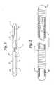
- FIG. 1shows a partially broken away, cross sectional view of one embodiment of the present invention.
- FIG. 1shows a guide wire 10 comprising a guide wire body or core wire 11 having a proximal segment 12, distal segment 14, and a medial segment 16.
- the medial segmentwill generally comprise the majority of the length of the guide wire 10 and has been broken as shown for purposes of illustrating other features of the invention.
- proximal, medial, and distalas it is used with reference to guide wire structures, will be well understood by one skilled in this art to mean structures of the guide wire as determined from the user's perspective.
- the distal segment 14 of a wire of this inventiongenerally means that portion of the guide wire which first enters the patient's anatomy when the device is utilized.
- the distal segment 14 of any particular guide wireis generally designed to be more flexible than the rest of the guide wire.
- the distal segment 14begins with a taper 13 in which the medial segment 16 of the guide wire body has a gradually reduced diameter. Taper 13 leads to distal segment 14, which, as shown in this embodiment has a lesser diameter than medial segment 16, or proximal segment.
- distal segment 14will generally be more flexible than medial segment 16.
- the diameter of distal segment 14may be reduced, for example, by centerless grinding
- jacket 17will be a non-metallic polymeric material, the polymer of coating 17 being different from that of guide wire body 11.
- one preferred polymer of coating 17is PEBAX polyetherimide.
- Polyurethane, nylon, and polytetrafluoroethylene (PTFE)are further examples of optional coatings which could be used with the present invention.
- Extruded polymer coatings or other heat-shrunk polymer coatingsalso may be utilized.
- a variety of other hydrophilic, hydrophobic or other coatingsthat are known to one skilled in this art can optionally be used with the present invention. As is shown in FIG.
- coating or jacket 17tends to make the overall diameter (arrows 15) of the guide wire more uniform.
- Polymer coatings contemplated by the present inventionoptionally may include radiopaque fillers such as barium salts in order to enhance the visibility of the guide wire when used with non-resonance imaging systems.
- Guide wire body 11is non-metallic, and in a preferred practice, polymeric.
- the overall diameter of the guide wire of at least the medial segment shown in FIG. 1 (at arrows 15)is approximately 0.035 inches.
- PEEKas is used in accordance with this invention is commercially available from many sources.
- a preferred sourceis Zeus Industrial Products, Inc. in Orangeburg, South Carolina, U.S.A. ( HTTP://www.zeusinc.com ).
- PEEKis preferred for use in the present invention because it is camber resistant, having little tendency to break when sharply bent. It is also thermally stable permitting other polymeric materials to be extruded over it without change in dimension.
- PEEKis also believed to be capable of being impregnated with glass fibers, e.g., to alter its handling characteristics.
- "Camber resistant” hereinmeans having the property or tendency not to be become curved when held in a circular package while being shipped. Camber resistance could also be described as not having the tendency to remain curved or circular even though guide wires are commercially shipped in circular carriers. The absence of camber means that medical personnel using a device of this invention can remove it from its generally circular shipping tube (the device may have been maintained in a circular configuration for several months while the device was in inventory and being shipped) and still be immediately useable, e.g., for catheter placement.
- Polyetheretherketone described abovealso has the property of not being easily broken when sharply bent, e.g., around human or other vasculature. PEEK also -tends to allow prolapsing without kinking or fracturing. This is also an advantage of the use of PEEK to make the guide wire body of this invention.
- the distal segment of a guide wire of the present inventionis generally more flexible than either of the proximal or medial segments.
- the polymer usedshould preferably be capable of being centerless ground. Being capable of being centerless ground means that the reduced diameter distal segment (14 in the FIG. 1 ) can easily be manufactured using conventional guide wire processing techniques.
- a second material from which guide wire body 11 can compriseis a carbon fiber commercially available from SGL Carbon Corp. of Charlotte, N.C., U.S.A.
- the SGL Carbon fibergenerally comprises bundled, helically-wound or twisted carbon fibers held together by means of an adhesive or other resin.
- a vinylester resinis a preferred adhesive or binder, the binder being applied by pultrusion of the wound carbon fibers or fiber bundles through a die.
- the helically-wound guide wire bodyhas at least 10 helical turns per foot. Helically-wound glass fibers, with an appropriate binder or adhesive, are believed to be similarly useable.
- Nylon fibersand "Isoplast” glass filled plastic fibers commercially available from Dow Chemical Corporation, are also believed to be useable in this structure.
- a structure so constructedcan be centerless ground, e.g., on the distal portion thereof, so as to reduce its diameter and increase its flexibility.
- Centerless grindingis a technique that is conventionally used to fabricate metallic guide wires. For example, centerless grinding is often used to reduce the diameter of a portion of a metal guide wire (e.g., the distal portion of a guide wire core wire), to increase distal tip flexibility. Centerless grinding was a technique that, prior to this invention, was not believed to be useable for non-metallic guide wires. Centerless grinding of a portion of the guide wire body is much easier to accomplish than the use of staggered length, parallel, longitudinal fibers as is described in the above-mentioned Osbourne U.S. '640 patent at col. 3 line 20.
- the polymeric materials which have been found to be useful for fabricating the guide wire core wire or guide wire bodyhave properties which are representative of the properties of any polymeric material from which a guide wire of this invention is to be fabricated.
- the polymeric materialmust have sufficiently longitudinal rigidity or stiffness so that the guide wire can be advanced within a patient's vasculature in much the same fashion as e.g., a conventional 0.035 in. (diameter) metal angiography wire.
- the materialmust also be camber resistant while also being resistant to prolapsing.
- a workable polymeric materialmust be capable of being fabricated to have properties and "feel" like conventional metal, e.g., medical grade stainless steel, guide wires.
- polymeric materials from which the instant guide wire body or core wire can be fabricatedare those that, with similar diameters, lengths, and coatings tend to perform in a medical procedure substantially the same as their metallic counterparts.
- guide wire body 11is substantially solid in section, substantially throughout its entire length. No interior lumens, or other void spaces are contemplated to be needed or necessary to practice the present invention presuming a polymeric material having the above characteristics is selected to fabricate the guide wire body.
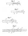
- FIG. 2illustrates a second embodiment of the present invention wherein the guide wire comprises a solid guide wire core wire or body 50 comprises a polymeric material as disclosed herein with a polymeric coil wire 52 substantially disposed therearound.
- Core wire 50 and coil 52may be attached to each other by any means suitable for adhering one polymeric material to another.
- an adhesivemay be used (at 54 and 56) to bond the guide wire components to each other.
- coil wire 52is wound around substantially the entire length of core wire 50 in this embodiment of the invention.
- FIG. 3is a further embodiment of the present invention in which a polymeric coil wire 60 is disposed on just the distal segment 62 of core wire 64.
- Polymeric or plastic coil wire materialsinclude PEI (polyetherimide commercially available from General Electric Plastics and sold under the trade designation “Ultem”), PES (polyether sulfone commercially available from BASF under the trade designation “Ultrason”) and various other high performance polymeric materials the identities of which would occur to one skilled in this art in view of this disclosure.
- Polymeric core 64may comprise PEEK or carbon fiber as is described above. Adhesive joints 66 bind the coil sire to the core wire.
- FIG. 4illustrates a variation of the structure shown in FIG. 3 in which a polymer-based jacket material 70 is disposed on the distal segment 72 of guide wire core wire 74.
- An optional adhesive 76may be used to adhere jacket material 70 to core wire 74.
- Illustrative polymeric jacket materialsinclude, polyurethane and Pebax as is described above.
- FIG. 5illustrates a further embodiment of the present invention in which the distal segment 80 of polymeric guide wire core wire 82 has been made more flexible by cutting or etching therein a series of radial cuts 84.
- the depth and distance between cuts 84may be adjusted to increase or decrease the flexibility of distal segment 80.
- the width of the cuts 84also may be increased or decreased to change device tip flexibility.
- an optional polymer-based coating 86is disposed over distal segment 80. Polymer coating 86 may be disposed over all or part of core wire 82 as is well known in the art.
- FIG. 6illustrates a further embodiment of the present invention in which a polymer guide wire core 90 has randomly disposed therein fibrous segments or fibers 92 of a second polymeric material.
- a PEEK core materialhaving therein randomly distributed glass fiber segments may be employed.
- Guide wire distal segment 94may have a reduced diameter as is shown.
- the guide wire coreoptionally may include a polymeric outer coating 96. Coating 96 may be hydrophilic, hydrophobic, or have other desirable characteristics.
- guide wires of the present inventioncan be used in situations where no magnetic resonance imaging is intended.
- the materials of the present inventionare considerably less expensive than conventional materials of guide wires for similar applications.
- guide wires of the present inventioncould be used to replace stainless steel diagnostic and angiography guide wires.
- Guide wires of the present inventionwould be especially applicable for those procedures where no steerability is needed.
Landscapes
- Health & Medical Sciences (AREA)
- Life Sciences & Earth Sciences (AREA)
- Biophysics (AREA)
- Pulmonology (AREA)
- Engineering & Computer Science (AREA)
- Anesthesiology (AREA)
- Biomedical Technology (AREA)
- Heart & Thoracic Surgery (AREA)
- Hematology (AREA)
- Animal Behavior & Ethology (AREA)
- General Health & Medical Sciences (AREA)
- Public Health (AREA)
- Veterinary Medicine (AREA)
- Media Introduction/Drainage Providing Device (AREA)
- Materials For Medical Uses (AREA)
Abstract
Description
- Not Applicable
- Guide wires are used in various medical procedures to gain vascular or non-vascular access to anatomical locations. The guide wire is initially introduced into the anatomy of a patient by means of a needle or other access device, which in many procedures pierces the patient's skin. The guide wire is then advanced to a chosen or targeted anatomical location to provide a means of tracking guidance and support for other diagnostic, interventional, or therapeutic medical devices having lumens which can follow or track over a guide wire. Once such other medical devices reach their desired anatomical location, the guide wire is or can be withdrawn. The physician then proceeds with the protocol of the procedure. A specific but non-limiting example of the above is the placement of a balloon catheter at the site of a vascular blockage. Suffice it to say, guide wires are one of the most commonly used medical devices where vascular or arterial access is desired.
- United States patent
5,705,014 to Schenck et al. discloses and claims methods for constructing instruments, specifically medical instruments, intended for use during a magnetic resonance (MR) imaging procedure. Essentially, the Schencket al. '014 patent discloses methods for selecting carbon fiber/substrate composite materials and for doping such composites with materials of differing degrees of magnetization. In accordance with the teaching of Schencket al., the composite materials are doped so that medical instruments manufactured from the doped composites do not interrupt the MR imaging process or distort an image developed therefrom. The entirety of the disclosure of the Schencket al. U.S. '014 patent is incorporated by reference herein. United States patent5,251,640 to Thomas A. Osbourne discloses a "Composite Wire Guide Shaft". The '640 patent discloses a composite guide shaft comprising a multifilar core (SeeFIGS. 3, 4, and 5 ) having multiple fibers wrapped therearound, the entire structure being held together by, for example, an adhesive matrix. In one embodiment of the device described in the '640 patent, a hollow core wire guide is contemplated. Metal core wires are also discussed. The disclosure of the '640 patent is also incorporated by reference herein. - Briefly, in one aspect, the present invention is an elongate guide wire comprising a guide wire body or core wire, the body having distal, medial, and proximal segments or portions. The guide wire body of the present invention is substantially non-metallic, non-woven, and non-braided. In a preferred practice a guide wire core wire of this invention is polymeric. In a preferred practice, a guide wire body of this invention is monofilament and is substantially solid in cross-section throughout substantially its entire length.
- A guide wire of this invention optionally may include a non-metallic coil wire. Guide wires of this invention are particularly useable during MR diagnostic and therapeutic procedures. In addition a guide wire of the present invention is kink resistant having the ability to prolapse, i.e., to be bent backward, without kinking. A guide wire of this invention also is pushable, steerable, and torque transmissive, primarily from its proximal end. These terms will be more extensively defined below.
- In a further embodiment of the present invention, the guide wire may comprise a non-metallic, helically-wound monofilar or multifilar core wire, or guide wire body embedded in a matrix material to provide a substantially solid (in cross-section) structure. A solid core wire structure of this aspect of the present invention may further comprise a coating such as is more completely described below.
- In an alternative embodiment, a helical core wire guide wire may comprise one or more helical non-metallic coil wires wound about the core wire. The helically-wound coil wires may be held in place by means of an adhesive. The coil wire may be located adjacent any or all of the proximal, medial and distal segments of the guide wire. Usually the coil wire is axially or radially disposed around the distal segment. The helically-wound coil wires of this further aspect of the present invention may be wound in the same or opposite directions. One skilled in the art will appreciate that the selection of fiber composition and direction(s) of wind will significantly include the torque transmissive characteristics of the guide wire.
- The term "guide wire" as used herein is to be broadly construed to mean essentially any wire-like structure of dimension and length which is intended to assist in the placement of a catheter or other medical device at a site of medical interest. Percutaneous procedures in which placement of a catheter or other device through the skin and into the vasculature, are a preferred category of medical procedures in which guide wires are used. Guide wire herein is intended to include but is not limited to what is usually referred to as a guide wire, a main wire, introducer guide wires, diagnostic, therapeutic or interventional guide wires, wire guides, and spring guide wires, but also includes exchange guide wires and extension wires. Dimensions of guide wires to which the present invention primarily applies fall in the range of about 0.012 in. to about 0.065 in. in diameter and about 30 cm to about 300 cm (or more) in length. Without limiting the generality of the foregoing, peripheral, cerebral (including neuro-interventional), guide wires or wire guides are within the contemplation of this definition. Guide wires of the present invention may include structure (e.g., on their extreme proximal segment) which permits them to be extended' during a procedure by connection in a second (extension wire) guide wire. Guide wires of this invention also will generally have a reduced diameter, increased flexibility tip. Guide wires of this invention optionally may be coated or treated with various further compositions, e.g., polymers or other compounds, to change their handling or performance characteristics such as to increase lubricity, to increase or decrease hydrophobicity,or to reduce thrombogenicity of their external surface. Guide wires of the invention may also be uncoated.
- A guide wire of the present invention is said to be "non-metallic". This term is intended to mean containing or comprising no metals, alloys, or other materials which respond in some manner to the magnetic or radio frequency fields generated in an MR imaging system. This definition is intended to exclude any non-ferrous metals which, while not necessarily interacting with the MR magnetic fields, exhibit what has become known as "antenna effect" by interaction with the radio frequency fields used in that procedure. Thus magnetic field deflection and "antenna effect" are completely eliminated by the use of the present invention.
- A preferred class of materials, which is non-metallic in accordance with this invention, comprises polymeric materials. Polymeric materials useable in the present invention are preferably hydrocarbon-based comprised of the elements of carbon and hydrogen. However, hydrocarbon polymer is useable in the present invention can, and often will, include oxygen, nitrogen, or other elements, usually as minor constituents.
- The present invention will now be discussed in detail, the understanding of which will be enhanced by reference to the attached figures in which:
FIG. 1 is a cross-sectional view (partially broken away) of one embodiment of the present invention:FIG. 2 is a second embodiment of the present invention in which a polymeric core and polymeric guide wire coil are used.FIG. 3 is a further embodiment of the present invention in which a polymeric coil is disposed on the distal end of the guide wire core wire.FIG. 4 is a cross sectional view of another embodiment of the present invention in which a polymeric jacket material is disposed on the distal end of the guide wire core wire.FIG. 5 is a cross sectional view of a further embodiment of the present invention in which a substantially uniform diameter polymeric guide wire core which has been partially radially cut or scored to increase distal segment or distal tip flexibility.FIG. 6 illustrates a guide wire core structure of the present invention comprising a polymeric core material in which there is disposed glass fiber segments and an optional external coating.- The invention will now be described with reference to the FIGs. noted above and the attached claims.
FIG. 1 shows a partially broken away, cross sectional view of one embodiment of the present invention.FIG. 1 shows a guide wire 10 comprising a guide wire body or core wire 11 having aproximal segment 12,distal segment 14, and amedial segment 16. It is to be understood that the medial segment will generally comprise the majority of the length of the guide wire 10 and has been broken as shown for purposes of illustrating other features of the invention. The terminology of proximal, medial, and distal, as it is used with reference to guide wire structures, will be well understood by one skilled in this art to mean structures of the guide wire as determined from the user's perspective. More specifically, thedistal segment 14 of a wire of this invention generally means that portion of the guide wire which first enters the patient's anatomy when the device is utilized. Thedistal segment 14 of any particular guide wire is generally designed to be more flexible than the rest of the guide wire. In that regard, thedistal segment 14 begins with ataper 13 in which themedial segment 16 of the guide wire body has a gradually reduced diameter.Taper 13 leads todistal segment 14, which, as shown in this embodiment has a lesser diameter thanmedial segment 16, or proximal segment. Thus,distal segment 14 will generally be more flexible thanmedial segment 16. The diameter ofdistal segment 14 may be reduced, for example, by centerless grinding - The embodiment shown in the
FIG. 1 includes an optional outer covering, coating, orjacket 17. Generally speakingjacket 17 will be a non-metallic polymeric material, the polymer ofcoating 17 being different from that of guide wire body 11. For example, one preferred polymer ofcoating 17 is PEBAX polyetherimide. Polyurethane, nylon, and polytetrafluoroethylene (PTFE) are further examples of optional coatings which could be used with the present invention. Extruded polymer coatings or other heat-shrunk polymer coatings also may be utilized. A variety of other hydrophilic, hydrophobic or other coatings that are known to one skilled in this art can optionally be used with the present invention. As is shown inFIG. 1 , coating orjacket 17 tends to make the overall diameter (arrows 15) of the guide wire more uniform. Polymer coatings contemplated by the present invention optionally may include radiopaque fillers such as barium salts in order to enhance the visibility of the guide wire when used with non-resonance imaging systems. - Guide wire body 11 is non-metallic, and in a preferred practice, polymeric. The overall diameter of the guide wire of at least the medial segment shown in
FIG. 1 (at arrows 15) is approximately 0.035 inches. A preferred polymeric material for guide wire body 11 polyetheretherketone, sold under the designation PEEK. PEEK as is used in accordance with this invention is commercially available from many sources. A preferred source is Zeus Industrial Products, Inc. in Orangeburg, South Carolina, U.S.A. (HTTP://www.zeusinc.com). PEEK is preferred for use in the present invention because it is camber resistant, having little tendency to break when sharply bent. It is also thermally stable permitting other polymeric materials to be extruded over it without change in dimension. PEEK is also believed to be capable of being impregnated with glass fibers, e.g., to alter its handling characteristics. "Camber resistant" herein means having the property or tendency not to be become curved when held in a circular package while being shipped. Camber resistance could also be described as not having the tendency to remain curved or circular even though guide wires are commercially shipped in circular carriers. The absence of camber means that medical personnel using a device of this invention can remove it from its generally circular shipping tube (the device may have been maintained in a circular configuration for several months while the device was in inventory and being shipped) and still be immediately useable, e.g., for catheter placement. - Polyetheretherketone described above also has the property of not being easily broken when sharply bent, e.g., around human or other vasculature. PEEK also -tends to allow prolapsing without kinking or fracturing. This is also an advantage of the use of PEEK to make the guide wire body of this invention. Last, as is noted above, the distal segment of a guide wire of the present invention is generally more flexible than either of the proximal or medial segments. In this instance, the polymer used should preferably be capable of being centerless ground. Being capable of being centerless ground means that the reduced diameter distal segment (14 in the
FIG. 1 ) can easily be manufactured using conventional guide wire processing techniques. - A second material from which guide wire body 11 can comprise is a carbon fiber commercially available from SGL Carbon Corp. of Charlotte, N.C., U.S.A. The SGL Carbon fiber generally comprises bundled, helically-wound or twisted carbon fibers held together by means of an adhesive or other resin. A vinylester resin is a preferred adhesive or binder, the binder being applied by pultrusion of the wound carbon fibers or fiber bundles through a die. In a preferred practice of the present invention, the helically-wound guide wire body has at least 10 helical turns per foot. Helically-wound glass fibers, with an appropriate binder or adhesive, are believed to be similarly useable. Nylon fibers, and "Isoplast" glass filled plastic fibers commercially available from Dow Chemical Corporation, are also believed to be useable in this structure. A structure so constructed can be centerless ground, e.g., on the distal portion thereof, so as to reduce its diameter and increase its flexibility.
- The ability to control the flexibility of the distal portion of a guide wire of the present invention using well-known centerless grinding processes is one of the surprising and unexpected advantages of the present invention. Centerless grinding is a technique that is conventionally used to fabricate metallic guide wires. For example, centerless grinding is often used to reduce the diameter of a portion of a metal guide wire (e.g., the distal portion of a guide wire core wire), to increase distal tip flexibility. Centerless grinding was a technique that, prior to this invention, was not believed to be useable for non-metallic guide wires. Centerless grinding of a portion of the guide wire body is much easier to accomplish than the use of staggered length, parallel, longitudinal fibers as is described in the above-mentioned Osbourne U.S. '640 patent at col. 3 line 20.
- The polymeric materials which have been found to be useful for fabricating the guide wire core wire or guide wire body have properties which are representative of the properties of any polymeric material from which a guide wire of this invention is to be fabricated. Specifically, the polymeric material must have sufficiently longitudinal rigidity or stiffness so that the guide wire can be advanced within a patient's vasculature in much the same fashion as e.g., a conventional 0.035 in. (diameter) metal angiography wire. As is noted above, the material must also be camber resistant while also being resistant to prolapsing. Last, a workable polymeric material must be capable of being fabricated to have properties and "feel" like conventional metal,e.g., medical grade stainless steel, guide wires. In summary, polymeric materials from which the instant guide wire body or core wire can be fabricated are those that, with similar diameters, lengths, and coatings tend to perform in a medical procedure substantially the same as their metallic counterparts.
- It is to be noted that guide wire body 11 is substantially solid in section, substantially throughout its entire length. No interior lumens, or other void spaces are contemplated to be needed or necessary to practice the present invention presuming a polymeric material having the above characteristics is selected to fabricate the guide wire body.
FIG. 2 illustrates a second embodiment of the present invention wherein the guide wire comprises a solid guide wire core wire orbody 50 comprises a polymeric material as disclosed herein with apolymeric coil wire 52 substantially disposed therearound.Core wire 50 andcoil 52 may be attached to each other by any means suitable for adhering one polymeric material to another. For example, an adhesive may be used (at 54 and 56) to bond the guide wire components to each other. It is to be noted thatcoil wire 52 is wound around substantially the entire length ofcore wire 50 in this embodiment of the invention.FIG. 3 is a further embodiment of the present invention in which apolymeric coil wire 60 is disposed on just thedistal segment 62 ofcore wire 64. Polymeric or plastic coil wire materials include PEI (polyetherimide commercially available from General Electric Plastics and sold under the trade designation "Ultem"), PES (polyether sulfone commercially available from BASF under the trade designation "Ultrason") and various other high performance polymeric materials the identities of which would occur to one skilled in this art in view of this disclosure.Polymeric core 64 may comprise PEEK or carbon fiber as is described above. Adhesive joints 66 bind the coil sire to the core wire.FIG. 4 illustrates a variation of the structure shown inFIG. 3 in which a polymer-basedjacket material 70 is disposed on the distal segment 72 of guidewire core wire 74. Anoptional adhesive 76 may be used to adherejacket material 70 tocore wire 74. Illustrative polymeric jacket materials include, polyurethane and Pebax as is described above.FIG. 5 illustrates a further embodiment of the present invention in which thedistal segment 80 of polymeric guidewire core wire 82 has been made more flexible by cutting or etching therein a series of radial cuts 84. As will be understood (and as is illustrated), the depth and distance betweencuts 84 may be adjusted to increase or decrease the flexibility ofdistal segment 80. The width of thecuts 84 also may be increased or decreased to change device tip flexibility. Also as is shown, an optional polymer-basedcoating 86 is disposed overdistal segment 80.Polymer coating 86 may be disposed over all or part ofcore wire 82 as is well known in the art.FIG. 6 illustrates a further embodiment of the present invention in which a polymerguide wire core 90 has randomly disposed therein fibrous segments orfibers 92 of a second polymeric material. For example, a PEEK core material having therein randomly distributed glass fiber segments may be employed. Guide wiredistal segment 94 may have a reduced diameter as is shown. The guide wire core optionally may include a polymericouter coating 96.Coating 96 may be hydrophilic, hydrophobic, or have other desirable characteristics.- It will be appreciated that guide wires of the present invention can be used in situations where no magnetic resonance imaging is intended. The materials of the present invention are considerably less expensive than conventional materials of guide wires for similar applications. For example, guide wires of the present invention could be used to replace stainless steel diagnostic and angiography guide wires. Guide wires of the present invention would be especially applicable for those procedures where no steerability is needed. Monofilament PIC wires, conventionally made of metal, also could be replaced by the present invention. Many of the above non-MR imaging applications, where metal (including shape memory alloys) are used could be accomplished using the present invention.
- The above description and examples are intended to be illustrative and not limiting of the present invention. One skilled in the art will appreciate that there may be many variations and alternatives suggested by the above invention. These variations and alternatives are intended to be within the scope of this invention as set forth in the following claims.
Claims (25)
- A guide wire comprising a core wire having distal, medial and proximal segments, the core wire substantially comprising a non-metallic, non-woven, material.
- A guide wire according to claim 1 wherein the core wire distal segment has a diameter which is less than that of the core wire medial and proximal segments.
- A guide wire according to claim 1 wherein the diameters of the core wire distal, medial, and proximal segments are all substantially the same.
- A guide wire according to claim 1 wherein the core wire has a polymeric coating thereon which covers substantially the entire length of the guide wire.
- A guide wire according to claim 1 wherein core wire has a tapered segment between the medal segment and the distal segment.
- A guide wire according to claim 1 wherein the core wire further comprises a taper which couples the medial segment and the distal segment and wherein substantially the entire core wire is covered with a polymeric material.
- A guide wire according to claim 1 wherein the core wire comprises a polymeric material.
- A guide wire according to claim 1 wherein the core wire comprises a polymeric material and the core wire is substantially completely covered with a second polymeric material.
- A guide wire according to claim 1 wherein the distal segment of the core wire has a diameter which is less than that of the medial segment.
- A guide wire comprising a core wire, the core wire having coupled proximal, medial, and distal segments, the core wire substantially completely comprising a polymeric material.
- A guide wire according to claim 10 wherein the core wire is coated with a second polymerical material.
- A guide wire according to claim 10 wherein the core wire comprises carbon fiber.
- A guide wire according to claim 10 wherein the core wire comprises polyetheretherketone.
- A guide wire according to claim 10 wherein the core wire is coated with PEBAX polyetherimide.
- A guide wire according to claim 10 wherein the core wire comprises polyetheretherketone, and the core wire is coated with polyetherimide.
- A guide wire according to claim 15 wherein the core wire distal segment is more flexible than either of the medial segment or the proximal segment.
- A guide wire according to claim 15 wherein the core wire distal segment is coupled to the core wire medial segment through a tapered segment and the distal segment has a diameter which is less than that of the medial segment.
- A guide wire according to claim 10 wherein the polyetherimide coating has a hydrophilic coating thereover.
- A guide wire comprising a core wire having coupled distal, medial, and proximal segments, the core wire comprising multiple, helically-wound, non-metallic fibers and a binder resin, the binder resin being uniformly dispersed between the fibers so as to fill any void space therebetween.
- A guide wire according to claim 19 which further comprises a coil wire disposed about the distal segment.
- A guide wire according to claim 19 where the non-metallic fibers comprise carbon and the binder resin comprises a vinyl ester.
- A guide wire according to claim 19 wherein the helically-wound fibers are wound to no more than 10 helices per foot of guide wire length.
- A guide wire comprising a core wire having coupled, distal, medial and proximal segments, the core wire comprising a single helically-wound non-metallic fiber and a binder resin, the binder resin being uniformly dispersed between the helices of the fiber so as to fill any void space therebetween and to provide steerability and torqueability to the guide wire.
- A guide wire according to claim 23 which further includes a coil wire disposed about the distal segment.
- A guide wire comprising a core wire, the core wire having coupled distal, medial and proximal segments, the core wire substantially comprising a non-metallic, non-woven, polymeric material, the guide wirecharacterized in that the polymeric material is non-oriented.
Priority Applications (1)
| Application Number | Priority Date | Filing Date | Title |
|---|---|---|---|
| EP12170339AEP2548604A1 (en) | 2001-01-26 | 2002-01-22 | Non-metallic guide wire |
Applications Claiming Priority (2)
| Application Number | Priority Date | Filing Date | Title |
|---|---|---|---|
| US09/770,342US20030060731A1 (en) | 2001-01-26 | 2001-01-26 | Non-metallic guide wire |
| EP02714761AEP1353720A2 (en) | 2001-01-26 | 2002-01-22 | Non-metallic guide wire |
Related Parent Applications (2)
| Application Number | Title | Priority Date | Filing Date |
|---|---|---|---|
| EP02714761.0Division | 2002-01-22 | ||
| EP02714761ADivisionEP1353720A2 (en) | 2001-01-26 | 2002-01-22 | Non-metallic guide wire |
Publications (2)
| Publication Number | Publication Date |
|---|---|
| EP1938858A1true EP1938858A1 (en) | 2008-07-02 |
| EP1938858B1 EP1938858B1 (en) | 2012-06-27 |
Family
ID=25088233
Family Applications (3)
| Application Number | Title | Priority Date | Filing Date |
|---|---|---|---|
| EP12170339ACeasedEP2548604A1 (en) | 2001-01-26 | 2002-01-22 | Non-metallic guide wire |
| EP07023141AExpired - LifetimeEP1938858B1 (en) | 2001-01-26 | 2002-01-22 | Non-metallic guide wire |
| EP02714761ACeasedEP1353720A2 (en) | 2001-01-26 | 2002-01-22 | Non-metallic guide wire |
Family Applications Before (1)
| Application Number | Title | Priority Date | Filing Date |
|---|---|---|---|
| EP12170339ACeasedEP2548604A1 (en) | 2001-01-26 | 2002-01-22 | Non-metallic guide wire |
Family Applications After (1)
| Application Number | Title | Priority Date | Filing Date |
|---|---|---|---|
| EP02714761ACeasedEP1353720A2 (en) | 2001-01-26 | 2002-01-22 | Non-metallic guide wire |
Country Status (5)
| Country | Link |
|---|---|
| US (4) | US20030060731A1 (en) |
| EP (3) | EP2548604A1 (en) |
| JP (2) | JP2004517694A (en) |
| CA (1) | CA2437798A1 (en) |
| WO (1) | WO2002058779A2 (en) |
Families Citing this family (26)
| Publication number | Priority date | Publication date | Assignee | Title |
|---|---|---|---|---|
| US20030055332A1 (en)* | 2001-09-14 | 2003-03-20 | Wolfgang Daum | MRI compatible guidewire |
| EP1660168B1 (en)* | 2003-09-05 | 2008-12-10 | Cook Urological Inc. | Double ended wire guide |
| DE102004028367A1 (en)* | 2004-06-11 | 2005-12-29 | Biotronik Vi Patent Ag | Catheter Guidewire especially for cardio-vascular procedures |
| US20060047224A1 (en)* | 2004-09-01 | 2006-03-02 | Ryan Grandfield | Polymer coated guide wire |
| US7142171B1 (en)* | 2005-04-14 | 2006-11-28 | Lockheed Martin Corporation | Helix radiating elements for high power applications |
| DE102005030472A1 (en) | 2005-06-28 | 2007-01-04 | Joachim-Georg Pfeffer | Rod-shaped body |
| JP2010524631A (en)* | 2007-04-23 | 2010-07-22 | インターヴェンショナル アンド サージカル イノヴェイションズ リミテッド ライアビリティ カンパニー | Guidewire with adjustable stiffness |
| US9387308B2 (en) | 2007-04-23 | 2016-07-12 | Cardioguidance Biomedical, Llc | Guidewire with adjustable stiffness |
| US7811623B2 (en)* | 2007-12-21 | 2010-10-12 | Innovatech, Llc | Marked precoated medical device and method of manufacturing same |
| US7714217B2 (en) | 2007-12-21 | 2010-05-11 | Innovatech, Llc | Marked precoated strings and method of manufacturing same |
| US8231927B2 (en) | 2007-12-21 | 2012-07-31 | Innovatech, Llc | Marked precoated medical device and method of manufacturing same |
| US8231926B2 (en) | 2007-12-21 | 2012-07-31 | Innovatech, Llc | Marked precoated medical device and method of manufacturing same |
| US8048471B2 (en)* | 2007-12-21 | 2011-11-01 | Innovatech, Llc | Marked precoated medical device and method of manufacturing same |
| DE102008012743A1 (en)* | 2008-03-05 | 2009-09-10 | Biotronik Vi Patent Ag | Catheter guidewire and method of making the same |
| US8444577B2 (en) | 2009-01-05 | 2013-05-21 | Cook Medical Technologies Llc | Medical guide wire |
| US9023070B2 (en) | 2010-05-13 | 2015-05-05 | Rex Medical, L.P. | Rotational thrombectomy wire coupler |
| US8764779B2 (en) | 2010-05-13 | 2014-07-01 | Rex Medical, L.P. | Rotational thrombectomy wire |
| US9795406B2 (en) | 2010-05-13 | 2017-10-24 | Rex Medical, L.P. | Rotational thrombectomy wire |
| US8663259B2 (en) | 2010-05-13 | 2014-03-04 | Rex Medical L.P. | Rotational thrombectomy wire |
| US8900652B1 (en) | 2011-03-14 | 2014-12-02 | Innovatech, Llc | Marked fluoropolymer surfaces and method of manufacturing same |
| EP2692365A1 (en)* | 2012-08-03 | 2014-02-05 | MaRVis Medical GmbH | Implantable or insertable MRI-detectable medical device having a coating comprising paramagnetic ions and a process for preparing it |
| US20160310041A1 (en)* | 2015-04-22 | 2016-10-27 | Acclarent, Inc. | Guidewire with navigation sensor |
| EP3415192B1 (en)* | 2017-06-16 | 2019-09-25 | Nano4Imaging GmbH | Guide wire for minimally invasive interventions and method for manufacturing a guide wire |
| EP3717922B1 (en) | 2017-12-03 | 2025-08-20 | Cook Medical Technologies, LLC | Mri compatible interventional wireguide |
| US11684759B2 (en)* | 2020-01-22 | 2023-06-27 | Abbott Cardiovascular Systems Inc. | Guidewire having varying diameters and method of making |
| CN111840755A (en)* | 2020-07-10 | 2020-10-30 | 广东海思卡尔医疗科技有限公司 | A guide wire for interventional therapy |
Citations (4)
| Publication number | Priority date | Publication date | Assignee | Title |
|---|---|---|---|---|
| US5251640A (en) | 1992-03-31 | 1993-10-12 | Cook, Incorporated | Composite wire guide shaft |
| WO1996026671A1 (en)* | 1995-02-28 | 1996-09-06 | Boston Scientific Corporation | Polymeric implements for torque transmission |
| US5705014A (en) | 1996-03-22 | 1998-01-06 | General Electric Company | Carbon fiber magnetic resonance compatible instruments |
| US5746701A (en)* | 1995-09-14 | 1998-05-05 | Medtronic, Inc. | Guidewire with non-tapered tip |
Family Cites Families (65)
| Publication number | Priority date | Publication date | Assignee | Title |
|---|---|---|---|---|
| US34695A (en)* | 1862-03-18 | Improved apparatus for preventing malt liquors from becoming flat | ||
| US573326A (en)* | 1896-12-15 | Island | ||
| CA1153264A (en)* | 1979-02-08 | 1983-09-06 | Hidenaga Yoshimura | Medical vascular guide wire and self-guiding type catheter |
| JPS5653513A (en)* | 1979-10-05 | 1981-05-13 | Mitsubishi Rayon Co | Wiring induction tool |
| US4657024A (en)* | 1980-02-04 | 1987-04-14 | Teleflex Incorporated | Medical-surgical catheter |
| US4672972A (en)* | 1984-08-13 | 1987-06-16 | Berke Howard R | Solid state NMR probe |
| US4653496A (en)* | 1985-02-01 | 1987-03-31 | Bundy Mark A | Transluminal lysing system |
| US4631155A (en)* | 1985-02-01 | 1986-12-23 | American Hoechst Corporation | Process for manufacture of surface-modified oriented polymeric film |
| US4748986A (en)* | 1985-11-26 | 1988-06-07 | Advanced Cardiovascular Systems, Inc. | Floppy guide wire with opaque tip |
| US4746919A (en)* | 1986-03-28 | 1988-05-24 | Rca Licensing Corporation | Remote control system with key function display provisions |
| US5028292A (en)* | 1987-03-16 | 1991-07-02 | Minnesota Mining And Manufacturing Company | Adhesive bonding to quasi-amorphous polymer surfaces |
| US5154705A (en)* | 1987-09-30 | 1992-10-13 | Lake Region Manufacturing Co., Inc. | Hollow lumen cable apparatus |
| US4917097A (en)* | 1987-10-27 | 1990-04-17 | Endosonics Corporation | Apparatus and method for imaging small cavities |
| US4867174A (en)* | 1987-11-18 | 1989-09-19 | Baxter Travenol Laboratories, Inc. | Guidewire for medical use |
| US5052404A (en)* | 1989-03-02 | 1991-10-01 | The Microspring Company, Inc. | Torque transmitter |
| US5084022A (en)* | 1989-10-04 | 1992-01-28 | Lake Region Manufacturing Company, Inc. | Graduated guidewire |
| US5135503A (en)* | 1990-05-16 | 1992-08-04 | Advanced Cardiovascular Systems, Inc. | Shaping ribbon for guiding members |
| US5040543A (en)* | 1990-07-25 | 1991-08-20 | C. R. Bard, Inc. | Movable core guidewire |
| US5135486A (en)* | 1990-08-31 | 1992-08-04 | Endosonics Corporation | Self-venting balloon dilitation catheter |
| EP0556316B1 (en)* | 1990-11-09 | 1997-01-22 | Boston Scientific Corporation | Guidewire for crossing occlusions in blood vessels |
| US5341818A (en)* | 1992-12-22 | 1994-08-30 | Advanced Cardiovascular Systems, Inc. | Guidewire with superelastic distal portion |
| US5167233A (en)* | 1991-01-07 | 1992-12-01 | Endosonics Corporation | Dilating and imaging apparatus |
| US5454788A (en)* | 1991-04-24 | 1995-10-03 | Baxter International Inc. | Exchangeable integrated-wire balloon catheter |
| US5203337A (en)* | 1991-05-08 | 1993-04-20 | Brigham And Women's Hospital, Inc. | Coronary artery imaging system |
| US5443907A (en)* | 1991-06-18 | 1995-08-22 | Scimed Life Systems, Inc. | Coating for medical insertion guides |
| US5183048A (en)* | 1991-06-24 | 1993-02-02 | Endosonics Corporation | Method and apparatus for removing artifacts from an ultrasonically generated image of a small cavity |
| US5333620A (en)* | 1991-10-30 | 1994-08-02 | C. R. Bard, Inc. | High performance plastic coated medical guidewire |
| US5313967A (en)* | 1992-07-24 | 1994-05-24 | Medtronic, Inc. | Helical guidewire |
| US5453575A (en)* | 1993-02-01 | 1995-09-26 | Endosonics Corporation | Apparatus and method for detecting blood flow in intravascular ultrasonic imaging |
| US5368037A (en)* | 1993-02-01 | 1994-11-29 | Endosonics Corporation | Ultrasound catheter |
| US5361764A (en)* | 1993-07-09 | 1994-11-08 | Grumman Aerospace Corporation | Magnetic resonance imaging foot coil assembly |
| US7476254B2 (en)* | 1993-11-01 | 2009-01-13 | Biomet Manufacturing Corporation | Compliant fixation for pelvis |
| US6673025B1 (en)* | 1993-12-01 | 2004-01-06 | Advanced Cardiovascular Systems, Inc. | Polymer coated guidewire |
| EP0673621B1 (en)* | 1994-03-18 | 1998-03-04 | Schneider (Europe) Ag | A magnetic resonance imaging system for tracking a medical appliance |
| US5447156A (en)* | 1994-04-04 | 1995-09-05 | General Electric Company | Magnetic resonance (MR) active invasive devices for the generation of selective MR angiograms |
| US5807236A (en)* | 1994-05-05 | 1998-09-15 | Imagyn Medical Inc. | Catheter with guidewire and rounded enlargement and method |
| US5445151A (en)* | 1994-06-23 | 1995-08-29 | General Electric Company | Method for blood flow acceleration and velocity measurement using MR catheters |
| US5636641A (en)* | 1994-07-25 | 1997-06-10 | Advanced Cardiovascular Systems, Inc. | High strength member for intracorporeal use |
| US5497785A (en)* | 1994-07-27 | 1996-03-12 | Cordis Corporation | Catheter advancing guidewire and method for making same |
| US5728079A (en)* | 1994-09-19 | 1998-03-17 | Cordis Corporation | Catheter which is visible under MRI |
| US5658264A (en)* | 1994-11-10 | 1997-08-19 | Target Therapeutics, Inc. | High performance spiral-wound catheter |
| US5664580A (en)* | 1995-01-31 | 1997-09-09 | Microvena Corporation | Guidewire having bimetallic coil |
| DE19531117C2 (en)* | 1995-08-24 | 1999-05-12 | Daum Gmbh | Use of a titanium alloy for instruments for interventional magnetic resonance imaging and methods for the treatment of such instruments |
| US5830155A (en)* | 1995-10-27 | 1998-11-03 | Cordis Corporation | Guidewire assembly |
| US5744958A (en)* | 1995-11-07 | 1998-04-28 | Iti Medical Technologies, Inc. | Instrument having ultra-thin conductive coating and method for magnetic resonance imaging of such instrument |
| US5782764A (en)* | 1995-11-07 | 1998-07-21 | Iti Medical Technologies, Inc. | Fiber composite invasive medical instruments and methods for use in interventional imaging procedures |
| US6436056B1 (en)* | 1996-02-28 | 2002-08-20 | Boston Scientific Corporation | Polymeric implements for torque transmission |
| US5836893A (en)* | 1996-03-08 | 1998-11-17 | Scimed Life Systems, Inc. | Intravascular guidewire |
| US5720411A (en)* | 1996-03-20 | 1998-02-24 | Advanced Structures, Inc. | Pressure vessels and end closures therefor |
| US5842989A (en)* | 1996-03-21 | 1998-12-01 | Elscint, Ltd. | Artifact reduction in magnetic resonance angiographic images |
| US5840046A (en)* | 1996-06-21 | 1998-11-24 | Medtronic, Inc. | Guidewire having hydrophilic coating |
| US5833631A (en)* | 1996-06-28 | 1998-11-10 | Target Therapeutics, Inc. | Fiber tip guidewire |
| US5881728A (en)* | 1996-07-26 | 1999-03-16 | Wisconsin Alumni Research Foundation | Digital subtraction magnetic resonance angiography with image artifact suppression |
| US5827201A (en)* | 1996-07-26 | 1998-10-27 | Target Therapeutics, Inc. | Micro-braided guidewire |
| WO1998014232A1 (en)* | 1996-10-03 | 1998-04-09 | Dubrul William R | Self coiling catheter |
| EP0868925B1 (en)* | 1997-03-31 | 2008-04-30 | Terumo Kabushiki Kaisha | Guide wire |
| NL1006254C2 (en)* | 1997-06-06 | 1998-12-08 | Cordis Europ | MRI-compatible guidewire. |
| US5891114A (en)* | 1997-09-30 | 1999-04-06 | Target Therapeutics, Inc. | Soft-tip high performance braided catheter |
| US5924987A (en)* | 1997-10-06 | 1999-07-20 | Meaney; James F. M. | Method and apparatus for magnetic resonance arteriography using contrast agents |
| US5986453A (en)* | 1997-11-07 | 1999-11-16 | Varian, Inc. | AC magnetic susceptibility control of superconducting materials in nuclear magnetic resonance (NMR) probes |
| EP0993843B1 (en)* | 1998-10-14 | 2006-04-26 | Terumo Kabushiki Kaisha | Radiation source delivery wire and catheter assembly for radiation therapy |
| JP2001009040A (en)* | 1999-06-30 | 2001-01-16 | Piolax Inc | Guide wire |
| US6203485B1 (en)* | 1999-10-07 | 2001-03-20 | Scimed Life Systems, Inc. | Low attenuation guide wire for intravascular radiation delivery |
| US6451026B1 (en)* | 1999-12-21 | 2002-09-17 | Advanced Cardiovascular Systems, Inc. | Dock exchange system for composite guidewires |
| US6602207B1 (en)* | 2000-07-19 | 2003-08-05 | Scimed Life Systems, Inc. | Guide wire stiffness transition element |
- 2001
- 2001-01-26USUS09/770,342patent/US20030060731A1/ennot_activeAbandoned
- 2002
- 2002-01-22EPEP12170339Apatent/EP2548604A1/ennot_activeCeased
- 2002-01-22JPJP2002559109Apatent/JP2004517694A/enactivePending
- 2002-01-22CACA002437798Apatent/CA2437798A1/ennot_activeAbandoned
- 2002-01-22EPEP07023141Apatent/EP1938858B1/ennot_activeExpired - Lifetime
- 2002-01-22WOPCT/US2002/001764patent/WO2002058779A2/enactiveApplication Filing
- 2002-01-22EPEP02714761Apatent/EP1353720A2/ennot_activeCeased
- 2008
- 2008-09-10JPJP2008232522Apatent/JP5123119B2/ennot_activeExpired - Lifetime
- 2009
- 2009-02-06USUS12/367,375patent/US20090143702A1/enactivePending
- 2013
- 2013-04-03USUS13/856,064patent/US20130289444A1/ennot_activeAbandoned
- 2016
- 2016-07-07USUS15/203,960patent/US20160310706A1/ennot_activeAbandoned
Patent Citations (4)
| Publication number | Priority date | Publication date | Assignee | Title |
|---|---|---|---|---|
| US5251640A (en) | 1992-03-31 | 1993-10-12 | Cook, Incorporated | Composite wire guide shaft |
| WO1996026671A1 (en)* | 1995-02-28 | 1996-09-06 | Boston Scientific Corporation | Polymeric implements for torque transmission |
| US5746701A (en)* | 1995-09-14 | 1998-05-05 | Medtronic, Inc. | Guidewire with non-tapered tip |
| US5705014A (en) | 1996-03-22 | 1998-01-06 | General Electric Company | Carbon fiber magnetic resonance compatible instruments |
Also Published As
| Publication number | Publication date |
|---|---|
| US20160310706A1 (en) | 2016-10-27 |
| EP1938858B1 (en) | 2012-06-27 |
| US20030060731A1 (en) | 2003-03-27 |
| WO2002058779A2 (en) | 2002-08-01 |
| JP2004517694A (en) | 2004-06-17 |
| CA2437798A1 (en) | 2002-08-01 |
| US20130289444A1 (en) | 2013-10-31 |
| JP5123119B2 (en) | 2013-01-16 |
| JP2009268888A (en) | 2009-11-19 |
| US20090143702A1 (en) | 2009-06-04 |
| EP1353720A2 (en) | 2003-10-22 |
| EP2548604A1 (en) | 2013-01-23 |
| WO2002058779A3 (en) | 2003-02-06 |
Similar Documents
| Publication | Publication Date | Title |
|---|---|---|
| US20160310706A1 (en) | Non-metallic guide wire | |
| EP1933921B1 (en) | Medical device coil | |
| US6652508B2 (en) | Intravascular microcatheter having hypotube proximal shaft with transition | |
| EP0759793B1 (en) | Catheter guide wire with multiple radiopacity | |
| US7540845B2 (en) | Medical device coil | |
| US7833175B2 (en) | Medical device coil | |
| US7641621B2 (en) | Elongated intra-lumenal medical device | |
| US20040167437A1 (en) | Articulating intracorporal medical device | |
| US7674239B2 (en) | Flexible introducer sheath | |
| US20040167438A1 (en) | Reinforced medical device | |
| JPH08508928A (en) | Catheter with kink-resistant distal tip | |
| JPH09501094A (en) | Untwisted spiral wound catheter | |
| US20220016396A1 (en) | Catheter With Embedded Core Wires And Shaping Ribbons | |
| US7815975B2 (en) | Catheter having polymer stiffener rings and method of making the same | |
| WO2010075000A1 (en) | Variable stiffness introducer sheath with transition zone | |
| EP1011491B1 (en) | Glass core guidewire compatible with magnetic resonance | |
| US20220096792A1 (en) | Medical device including shaft with flat wire coil | |
| US20220072272A1 (en) | Catheter including a bamboo structural support member | |
| US20020133141A1 (en) | Instrument shaft | |
| US20230310797A1 (en) | Multi-filar catheter body construction | |
| JP2672714B2 (en) | Untwisted spiral wound catheter |
Legal Events
| Date | Code | Title | Description |
|---|---|---|---|
| PUAI | Public reference made under article 153(3) epc to a published international application that has entered the european phase | Free format text:ORIGINAL CODE: 0009012 | |
| 17P | Request for examination filed | Effective date:20071218 | |
| AC | Divisional application: reference to earlier application | Ref document number:1353720 Country of ref document:EP Kind code of ref document:P | |
| AK | Designated contracting states | Kind code of ref document:A1 Designated state(s):AT BE CH CY DE DK ES FI FR GB GR IE IT LI LU MC NL PT SE TR | |
| AKX | Designation fees paid | Designated state(s):CH DE FR GB LI | |
| 17Q | First examination report despatched | Effective date:20090212 | |
| GRAP | Despatch of communication of intention to grant a patent | Free format text:ORIGINAL CODE: EPIDOSNIGR1 | |
| GRAS | Grant fee paid | Free format text:ORIGINAL CODE: EPIDOSNIGR3 | |
| GRAA | (expected) grant | Free format text:ORIGINAL CODE: 0009210 | |
| AC | Divisional application: reference to earlier application | Ref document number:1353720 Country of ref document:EP Kind code of ref document:P | |
| AK | Designated contracting states | Kind code of ref document:B1 Designated state(s):CH DE FR GB LI | |
| REG | Reference to a national code | Ref country code:GB Ref legal event code:FG4D | |
| REG | Reference to a national code | Ref country code:CH Ref legal event code:EP | |
| REG | Reference to a national code | Ref country code:DE Ref legal event code:R096 Ref document number:60243237 Country of ref document:DE Effective date:20120823 | |
| PLBE | No opposition filed within time limit | Free format text:ORIGINAL CODE: 0009261 | |
| STAA | Information on the status of an ep patent application or granted ep patent | Free format text:STATUS: NO OPPOSITION FILED WITHIN TIME LIMIT | |
| 26N | No opposition filed | Effective date:20130328 | |
| REG | Reference to a national code | Ref country code:DE Ref legal event code:R097 Ref document number:60243237 Country of ref document:DE Effective date:20130328 | |
| PGFP | Annual fee paid to national office [announced via postgrant information from national office to epo] | Ref country code:CH Payment date:20140129 Year of fee payment:13 | |
| REG | Reference to a national code | Ref country code:CH Ref legal event code:PL | |
| PG25 | Lapsed in a contracting state [announced via postgrant information from national office to epo] | Ref country code:CH Free format text:LAPSE BECAUSE OF NON-PAYMENT OF DUE FEES Effective date:20150131 Ref country code:LI Free format text:LAPSE BECAUSE OF NON-PAYMENT OF DUE FEES Effective date:20150131 | |
| REG | Reference to a national code | Ref country code:FR Ref legal event code:PLFP Year of fee payment:15 | |
| REG | Reference to a national code | Ref country code:FR Ref legal event code:PLFP Year of fee payment:16 | |
| REG | Reference to a national code | Ref country code:FR Ref legal event code:PLFP Year of fee payment:17 | |
| PGFP | Annual fee paid to national office [announced via postgrant information from national office to epo] | Ref country code:FR Payment date:20201210 Year of fee payment:20 | |
| PGFP | Annual fee paid to national office [announced via postgrant information from national office to epo] | Ref country code:DE Payment date:20210112 Year of fee payment:20 Ref country code:GB Payment date:20210113 Year of fee payment:20 | |
| REG | Reference to a national code | Ref country code:DE Ref legal event code:R071 Ref document number:60243237 Country of ref document:DE | |
| REG | Reference to a national code | Ref country code:GB Ref legal event code:PE20 Expiry date:20220121 | |
| PG25 | Lapsed in a contracting state [announced via postgrant information from national office to epo] | Ref country code:GB Free format text:LAPSE BECAUSE OF EXPIRATION OF PROTECTION Effective date:20220121 |