EP1935358A1 - Bone anchoring device - Google Patents
Bone anchoring deviceDownload PDFInfo
- Publication number
- EP1935358A1 EP1935358A1EP06026705AEP06026705AEP1935358A1EP 1935358 A1EP1935358 A1EP 1935358A1EP 06026705 AEP06026705 AEP 06026705AEP 06026705 AEP06026705 AEP 06026705AEP 1935358 A1EP1935358 A1EP 1935358A1
- Authority
- EP
- European Patent Office
- Prior art keywords
- receiving part
- rod
- bone anchoring
- locking
- locking device
- Prior art date
- Legal status (The legal status is an assumption and is not a legal conclusion. Google has not performed a legal analysis and makes no representation as to the accuracy of the status listed.)
- Granted
Links
- 210000000988bone and boneAnatomy0.000titleclaimsabstractdescription68
- 238000004873anchoringMethods0.000titleclaimsabstractdescription60
- 239000007943implantSubstances0.000description4
- 238000012986modificationMethods0.000description4
- 230000004048modificationEffects0.000description4
- 238000001356surgical procedureMethods0.000description3
- 230000004323axial lengthEffects0.000description2
- 238000010276constructionMethods0.000description2
- 230000001419dependent effectEffects0.000description1
- 238000011161developmentMethods0.000description1
- 230000018109developmental processEffects0.000description1
- 206010039722scoliosisDiseases0.000description1
Images


Classifications
- A—HUMAN NECESSITIES
- A61—MEDICAL OR VETERINARY SCIENCE; HYGIENE
- A61B—DIAGNOSIS; SURGERY; IDENTIFICATION
- A61B17/00—Surgical instruments, devices or methods
- A61B17/56—Surgical instruments or methods for treatment of bones or joints; Devices specially adapted therefor
- A61B17/58—Surgical instruments or methods for treatment of bones or joints; Devices specially adapted therefor for osteosynthesis, e.g. bone plates, screws or setting implements
- A61B17/68—Internal fixation devices, including fasteners and spinal fixators, even if a part thereof projects from the skin
- A61B17/70—Spinal positioners or stabilisers, e.g. stabilisers comprising fluid filler in an implant
- A61B17/7001—Screws or hooks combined with longitudinal elements which do not contact vertebrae
- A61B17/7032—Screws or hooks with U-shaped head or back through which longitudinal rods pass
- A—HUMAN NECESSITIES
- A61—MEDICAL OR VETERINARY SCIENCE; HYGIENE
- A61B—DIAGNOSIS; SURGERY; IDENTIFICATION
- A61B17/00—Surgical instruments, devices or methods
- A61B17/56—Surgical instruments or methods for treatment of bones or joints; Devices specially adapted therefor
- A61B17/58—Surgical instruments or methods for treatment of bones or joints; Devices specially adapted therefor for osteosynthesis, e.g. bone plates, screws or setting implements
- A61B17/68—Internal fixation devices, including fasteners and spinal fixators, even if a part thereof projects from the skin
- A61B17/70—Spinal positioners or stabilisers, e.g. stabilisers comprising fluid filler in an implant
- A61B17/7001—Screws or hooks combined with longitudinal elements which do not contact vertebrae
- A61B17/7035—Screws or hooks, wherein a rod-clamping part and a bone-anchoring part can pivot relative to each other
- A61B17/7037—Screws or hooks, wherein a rod-clamping part and a bone-anchoring part can pivot relative to each other wherein pivoting is blocked when the rod is clamped
- A—HUMAN NECESSITIES
- A61—MEDICAL OR VETERINARY SCIENCE; HYGIENE
- A61B—DIAGNOSIS; SURGERY; IDENTIFICATION
- A61B17/00—Surgical instruments, devices or methods
- A61B17/56—Surgical instruments or methods for treatment of bones or joints; Devices specially adapted therefor
- A61B17/58—Surgical instruments or methods for treatment of bones or joints; Devices specially adapted therefor for osteosynthesis, e.g. bone plates, screws or setting implements
- A61B17/68—Internal fixation devices, including fasteners and spinal fixators, even if a part thereof projects from the skin
- A61B17/74—Devices for the head or neck or trochanter of the femur
Definitions
- the inventionrelates to a bone anchoring device comprising a shank to be anchored in a bone or a vertebra and a receiving part connected to the shank for receiving a rod.
- the rodis locked by means of a locking device having an engagement structure for the engagement with a tool, the engagement structure being provided at the outer circumference of the locking device.
- the engagement structureprojects above the receiving part but does not project beyond the receiving part in a lateral direction.
- the inventionrelates to a polyaxial bone screw wherein the head of the screw and a rod can be fixed independently and which has a reduced size.
- US 6,224,598 B1discloses a threaded plug closure adapted for use in securing a rod member to a bone screw implant, said closure comprising a plug having a threaded cylindricallyshaped outer surface, said plug being received between a pair of arms of a medical implant during use, a central coaxial bore passing entirely through that plug, said central bore having an internal threaded surface which is shaped to receive a set screw.
- the plug closure and the set screwcan be independently installed and the set screw tightened to cooperatively provide capture and locking of the rod in order to secure the rod against translational and rotational movement relative to the bone screw.
- US 2003/0100896 A1discloses a bone anchoring device with a shank and a receiving part connected to it for connecting to a rod.
- the receiving parthas a recess having a U-shaped cross section for receiving the rod forming two open legs.
- An internal threadis provided on the open legs.
- a locking assemblyis provided comprising a nut member with an external thread which cooperates with the internal thread of the legs and a set screw.
- the nut memberhas on one end slits for engagement with a screw tool.
- the shankhas a spherically-shaped head which is pivotably held in the receiving part and a pressure element is provided which exerts pressure on the head when the nut member is tightened. By tightening the set screw the rod is fixed in the receiving part.
- the rod and the headcan be fixed independently from each other.
- the internal thread and the cooperating external thread of the nut memberare designed as a flat thread.
- the implanthas a compact design, since an outer ring or nut to prevent splaying of the legs is not necessary.
- US 6,063,090discloses a bone anchoring device with a locking assembly consisting of two parts, a tensioning screw fixing the spherical head via an insert without jamming the rod and a tension means fixing the rod.
- US 2006/0036244 A1also discloses a bone anchoring device with a two part locking cap for fixing the head and the rod independently.
- the tensioning screwhas a coaxial recess with a structure for engagement with a tool.
- the outer diameter of the locking deviceis under various aspects determined by the required tightening torque and the thread form.
- the overall dimensions of the upper portion of the bone anchoring deviceare determined by the size of the locking device. For certain applications, it is crucial to have the distance between one bone anchoring device and a neighboring bone anchoring device as small as possible, for example for correcting scoliosis in infants or for the application in the cervical region of the spine.
- the objectis solved by a bone anchoring device according to claim 1. Further developments of the bone anchoring device are given in the dependent claims.
- the locking device used in the bone anchoring device according to the inventionhas a structure for engagement with a tool which is provided at the outer surface in the upper part of the locking device. Hence, the size of the bone anchoring device in the direction of the rod axis can be reduced.
- the locking devicehas an improved accessibility for the tool which facilitates the handling during surgery.
- the bone anchoring device with such a reduced size and improved accessibilityis particularly suitable for the application in paediatric surgery or for applications to the cervical spine or other areas where a limited available space requires compact implants.
- the locking deviceis designed such that a stop provides safety against disassembly in use.
- the bone anchoring devicehas the advantage that it can be used with the choice of a locking device in two ways. If a single part locking device is selected, it is possible to simultaneously lock the head in the polyaxial position and to fix the rod. If a two part locking device is selected, it is possible to separately lock the head and fix the rod.
- the bone anchoring deviceis compact in size since it is not necessary to use an outer nut or ring to prevent splaying of the legs of the receiving part.
- the bone anchoring deviceincludes a screw element 1 having a shank 2 with a bone thread (not shown) and a head 3.
- the head 3has the shape of a segment of a sphere.
- the head 3comprises a recess 3a for engagement with a tool.
- the screw element 1is received in a receiving part 4 which has a first end 5 and a second end 6 and is of approximately cylindrical construction. The two ends are perpendicular to a longitudinal axis L. Coaxially with the longitudinal axis L, a bore 7 is provided which extends from the first end 6 to a predetermined distance from the second end 6.
- an opening 8is provided, the diameter of which is smaller than the diameter of the bore 7.
- the coaxial bore 7tapers towards the opening 8.
- the section 9can have any other shapes such as, for example, a conical shape.
- the receiving part 4further has a U-shaped recess 10 which starts at the first end 5 and extends in the direction of the second end 6 to a distance from the second end 6.
- a U-shaped recess 10which starts at the first end 5 and extends in the direction of the second end 6 to a distance from the second end 6.
- two free legs 11, 12are formed ending towards the first end 5.
- An internal thread 13is provided on the inner surface of the legs 11, 12.
- the internal threadis a flat thread having horizontal upper and lower thread flanks.
- a pressure element 14which has a substantially cylindrical construction with an outer diameter sized so as to allow the pressure element 14 to be introduced into the bore 7 of the receiving part and to be moved in the axial direction.
- the pressure element 14On its lower side facing towards the second end 6, the pressure element 14 comprises a recess 15 cooperating with the head 3.
- the recess 15can be spherically-shaped so as to match the contour of the spherical section of the head 3.
- the pressure element 14On its opposite side the pressure element 14 has a U-shaped recess 16 by means of which two free legs 17, 18 are formed.
- the lateral diameter of this U-shaped recessis selected such that a rod 20 with a diameter D which is to be received in the receiving part 4 can be inserted into the recess 16 and guided laterally therein.
- the depth of the U-shaped recess 16is larger than the diameter D of the rod 20 so that the legs 17, 18 extend above the surface of the rod 20 when the rod is inserted.
- the pressure elementfurther comprises a recess 21 at the inner side of the legs 17, 18 adjacent to the upper end.
- a bore 19is provided in the pressure element for accessing the head 3 of the screw element with a tool.
- the pressure element 17 and the receiving part 4can have crimp bores 50, 50a on opposite sides, respectively, in order to loosely hold the pressure element 14 within a receiving part in a position where the U-shaped recess 16 of the pressure element and the U-shaped recess 10 of the receiving part are aligned.
- the bone anchoring devicefurther comprises a locking device 30.
- the locking device 30includes, as shown in particular in Figs. 1 to 6 a first locking member 31 and a second member 32.
- the first locking member 31has a first end 33 and a second end 34 and a portion with a substantially cylindrical shape with an external thread 35 on the outer surface of that portion.
- the external thread 35is a flat thread which matches the internal thread 13 of the receiving part 4.
- the first locking member 30further comprises an axial bore 36 extending through the entire first locking member.
- the coaxial bore 36is provided with an internal thread 37 in at least a portion thereof, the portion corresponding approximately to the outer threaded surface portion of the first locking member.
- the internal thread 37is in the embodiment shown formed as a metric thread.
- the axial length of the threaded outer surface portion with the external thread 35 of the first locking member 31is such that the external thread 35 cooperates with the internal thread 13 of the legs 11, 12.
- the first locking member 31comprises adjacent to or in the vicinity of its first end 33 an engagement structure 38 which is provided at the circumference and which can be shaped as a polygon.
- the outer diameter of the engagement structure 38 in the embodiment shownis larger than the outer diameter of the external thread 35 of the locking member. Hence, the engagement structure 38 can form a stop when the first locking member is tightened.
- the maximum outer diameter of the engagement structure 38is equal to or smaller than the outer diameter of the receiving part measured between opposite sides of the legs, as can particularly be seen in Figs. 2 and 3 . Hence, the engagement structure 38 does not laterally project beyond the outer contour of the receiving part 4.
- the minimum outer diameteris larger than the inner diameter of the internal thread 13.
- the engagement structure 38serves for engagement with a tool in a form-fit manner. It needs not to be in the shape of a polygon, but can have other shapes.
- the outer contour of the engagement structurecan be triangular, square, star-shaped, circular with two opposite flattened sides, or otherwise shaped.
- the first locking member 31Adjacent to its first end 33 the first locking member 31 comprises a recess 40 which serves for accommodating a part of the second locking member described below.
- the total length of the first locking member 31 in the axial directionis such that, as shown in Fig. 3 , in an assembled state the first locking member 31 presses with its second end 34 on to the legs 17, 18 of the pressure element 14 which in turn presses onto the head.
- the second locking member 32is a screw which is to be screwed into the coaxial bore 36 of the first locking member 31.
- the second locking member 32comprises a thread free section with an annular shoulder the outer diameter of which is slightly smaller than the inner diameter of the recess 40 of the first locking member, so that the shoulder 41 can be accommodated in the recess 40.
- the recess 40forms a stop for screwing-in the second locking member 32.
- the second locking member 32comprises a recess 42 at the end where the annular shoulder is provided for engagement with a tool.
- the recess 42can be shaped as a hexagon recess or can have axial grooves arranged in a shape of a star.
- the axial length of the second locking member 32is such that when the second locking member 32 is inserted into the first locking member and the locking device is screwed-in between the legs of the receiving part, the second locking member presses onto the rod 20, but does not contact the pressure element 14. As can be seen in Fig.3 , there is a gap 43 between the bottom of the recess 20 of the pressure element and the lower side of the second locking member.
- the shoulder 41can serve for gripping the second locking member in order to assemble it with the first locking member and to provide a stop.
- At least two usually preassembled bone anchoring deviceseach comprising a screw element 1, the receiving part 4 and the pressure element 14 are screwed into the bone.
- the rod 20is inserted into the U-shaped recess 10 of the receiving part 4.
- the locking device 30comprising the first locking element 31 and the second locking element 32 which can be preassembled, is screwed-in between the legs 11, 12 of the receiving part 4.
- the first locking element 31is then tightened by applying a tool (not shown) to the engagement structure 38 until the first locking member 31 presses onto the free legs of the pressure element.
- the pressure element 14exerts a pressure onto the head 3 of the screw element 1 to lock the head 3 in its angular position within the receiving part 4.
- the stop provided by the engagement structure 38limits the applied force to a specific value.
- the rod 20When the head is locked, the rod 20 is still slidable in the receiving part.
- the second locking member 32By tightening the second locking member 32 the second locking member 32 moves downwards and presses onto the rod to fix the rod in its position.
- the force exerted onto the rodcan be well defined using the stop provided by the annular shoulder 41 abutting against the bottom of recess 40.
- the first locking memberBy means of providing the engagement structure 38 on the outer circumference of the first locking member the first locking member can be made smaller in its dimensions, in particular, with a smaller diameter of the outer threaded surface section. If the first locking member 31 can be made with a smaller outer diameter,in turn, the receiving part can be made with a smaller outer diameter. As a result thereof, the distance between two bone anchoring devices in the direction of the rod can be made smaller.
- the shoulder 41facilitates handling of the second locking member.
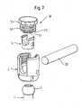
- a second embodiment of the bone anchoring deviceis shown in Fig. 7 to 9a and 9b . Parts which are identical to the first embodiment are designated with the same reference numerals and the description thereof will not be repeated.
- the bone anchoring device according to the second embodimentcomprises a single part locking device 50.
- the single part locking deviceis an inner screw which can be screwed between the legs 11, 12 of the receiving part 4.
- the thread 55 of the screwis in this embodiment a flat thread cooperating with the flat thread provided at the legs.
- the inner screwOn its side facing the pressure element 14 the inner screw has a projection 51 the diameter of which is just as large that the projection 51 can press onto the rod 20 without touching the pressure element.
- the length of the single part locking device 50 and the length of the cylindrical projection 51is such that as shown in Fig. 8 in the tightened state the cylindrical projection 51 contacts the rod and there is a gap 52 between the lower surface 53 of the single part locking device and the legs 17, 18 of the pressure element 14.
- the single part locking device 50comprises an engagement structure 54, which can have a polygon shape for engagement with a tool.
- the engagement structure 54is similar to the engagement structure 38 of the first locking element 31 of the two-part locking device 30 of the first embodiment.
- the outer diameter Dis smaller than the outer diameter D R of the receiving part 4 in the region of the legs.
- the outer diameter D'is only sligtly larger than the inner diameter of the inner thread D T .
- the engagement structureprojects above the receiving part 4. Therefore the tightening of the locking element with a tool during surgery is facilitated since the engagement structure is easily accessible with the tool.
- the single part locking device 50presses onto the rod which in turn presses onto the pressure element 14 to fix the head 3 in the receiving part 4. Hence, the rod and the head are fixed simultaneously.
- Fig. 10shows a third embodiment of the bone anchoring device. It differs from the second embodiment mainly by the shape of the pressure element. All other parts are the same.
- the pressure element 140differs from the pressure element 14 of the first and second embodiment in has short legs 141, 142 which do not project above the rod when the rod is inserted. All other features are the same as that of the pressure element 14.
- the pressure element 140does not have a recess for receiving the rod and also no legs. It can be formed as a pressure disk.
- the single part locking element 30does not have a projection 51 for pressing onto the rod.
- FIG. 11schematically shows the locking device 30 and the pressure element 14 of the bone anchoring device according to the first embodiment to be used as an upgrade of an existing polyaxial bone screw with a single part locking element.
- a known polyaxial bone screw 200has a single part locking element 250 in form of a set screw and a pressure disk 214.
- Known anchoring devices with a two-part locking devicewould have a larger size in terms of the outer diameter of the receiving part compared to the bone anchoring device having the single part locking element 250. It is, however, possible to upgrade the existing bone anchoring device 200 by exchanging the set screw 250 and the pressure disk 214 with the locking device 30 and the pressure element 14 according to the first embodiment.
- a bone anchoring devicewith minimized dimensions and with the advantage of being able to fix the rod and the head independently is provided.
- Fig. 12shows a modular system of bone anchoring devices including the bone anchoring devices of the first, second and third embodiments.
- the single-part and the two-part locking devicescan be used interchangeably if the pressure element 14 is used.
- the single-part locking devicecan be used with the pressure element 14 or 140.
- the surgeoncan select whether the single part locking device 50 or the two-part locking device 30 is to be used in conjunction with the same bone anchoring device.
- a single part locking device for simultaneous locking of head and rodis of advantage, in particular, if the fixation has to take place rapidly.
- the section 10 of the receiving part 4 against which the head 3 restsneeds not to be spherically-shaped but can have any other shape as long as the head 3 is held by the edge of the opening 8 like a ball and socket joined.
- the receiving partis designed so as to allow the introduction of the head from the bottom of the receiving part from the second end.
Landscapes
- Health & Medical Sciences (AREA)
- Orthopedic Medicine & Surgery (AREA)
- Life Sciences & Earth Sciences (AREA)
- Surgery (AREA)
- Neurology (AREA)
- Heart & Thoracic Surgery (AREA)
- Engineering & Computer Science (AREA)
- Biomedical Technology (AREA)
- Nuclear Medicine, Radiotherapy & Molecular Imaging (AREA)
- Medical Informatics (AREA)
- Molecular Biology (AREA)
- Animal Behavior & Ethology (AREA)
- General Health & Medical Sciences (AREA)
- Public Health (AREA)
- Veterinary Medicine (AREA)
- Surgical Instruments (AREA)
Abstract
Description
- The invention relates to a bone anchoring device comprising a shank to be anchored in a bone or a vertebra and a receiving part connected to the shank for receiving a rod. The rod is locked by means of a locking device having an engagement structure for the engagement with a tool, the engagement structure being provided at the outer circumference of the locking device. The engagement structure projects above the receiving part but does not project beyond the receiving part in a lateral direction. In particular the invention relates to a polyaxial bone screw wherein the head of the screw and a rod can be fixed independently and which has a reduced size.
US 6,224,598 B1 discloses a threaded plug closure adapted for use in securing a rod member to a bone screw implant, said closure comprising a plug having a threaded cylindricallyshaped outer surface, said plug being received between a pair of arms of a medical implant during use, a central coaxial bore passing entirely through that plug, said central bore having an internal threaded surface which is shaped to receive a set screw. The plug closure and the set screw can be independently installed and the set screw tightened to cooperatively provide capture and locking of the rod in order to secure the rod against translational and rotational movement relative to the bone screw.US 2003/0100896 A1 discloses a bone anchoring device with a shank and a receiving part connected to it for connecting to a rod. The receiving part has a recess having a U-shaped cross section for receiving the rod forming two open legs. An internal thread is provided on the open legs. A locking assembly is provided comprising a nut member with an external thread which cooperates with the internal thread of the legs and a set screw. The nut member has on one end slits for engagement with a screw tool. The shank has a spherically-shaped head which is pivotably held in the receiving part and a pressure element is provided which exerts pressure on the head when the nut member is tightened. By tightening the set screw the rod is fixed in the receiving part. Hence, the rod and the head can be fixed independently from each other. The internal thread and the cooperating external thread of the nut member are designed as a flat thread. The implant has a compact design, since an outer ring or nut to prevent splaying of the legs is not necessary.US 6,063,090 discloses a bone anchoring device with a locking assembly consisting of two parts, a tensioning screw fixing the spherical head via an insert without jamming the rod and a tension means fixing the rod.US 2006/0036244 A1 also discloses a bone anchoring device with a two part locking cap for fixing the head and the rod independently. The tensioning screw has a coaxial recess with a structure for engagement with a tool.- The outer diameter of the locking device is under various aspects determined by the required tightening torque and the thread form. In turn, the overall dimensions of the upper portion of the bone anchoring device are determined by the size of the locking device. For certain applications, it is crucial to have the distance between one bone anchoring device and a neighboring bone anchoring device as small as possible, for example for correcting scoliosis in infants or for the application in the cervical region of the spine.
- It is the object of the invention to provide a bone anchoring device with a locking device which has the same reliability as the known devices but which has significantly smaller dimensions of the upper portion in the direction of the rod axis. The object is solved by a bone anchoring device according to
claim 1. Further developments of the bone anchoring device are given in the dependent claims. - The locking device used in the bone anchoring device according to the invention has a structure for engagement with a tool which is provided at the outer surface in the upper part of the locking device. Hence, the size of the bone anchoring device in the direction of the rod axis can be reduced. The locking device has an improved accessibility for the tool which facilitates the handling during surgery. The bone anchoring device with such a reduced size and improved accessibility is particularly suitable for the application in paediatric surgery or for applications to the cervical spine or other areas where a limited available space requires compact implants. The locking device is designed such that a stop provides safety against disassembly in use.
- It is further possible to upgrade existing polyaxial bone screws which have a single part locking device with the pressure element and the two part locking device according to the invention. Further, the bone anchoring device has the advantage that it can be used with the choice of a locking device in two ways. If a single part locking device is selected, it is possible to simultaneously lock the head in the polyaxial position and to fix the rod. If a two part locking device is selected, it is possible to separately lock the head and fix the rod.
- Further, the bone anchoring device is compact in size since it is not necessary to use an outer nut or ring to prevent splaying of the legs of the receiving part.
- Further features and advantages of the invention will become apparent from the description of embodiments in conjunction with the accompanying drawings.
Fig. 1 shows a perspective exploded view of a bone anchoring device according to a first embodiment of the invention.Fig. 2 shows a perspective view of the bone anchoring device in an assembled state.Fig. 3 shows a sectional view of the bone anchoring device in an assembled state the section being taken in a plane perpendicular to the rod axis.Fig. 4 shows a sectional view of the locking device according to the first embodiment.Fig. 5 shows a side view of the locking device ofFig. 4 .Fig. 6 shows a top view of the locking device according toFig. 4 .Fig. 7 shows a perspective exploded view of the bone anchoring device according to a second embodiment.Fig. 8 shows a sectional view of the bone anchoring device according to the second embodiment in an assembled state, the section being taken in a plane perpendicular to the rod axis.Fig. 9a shows an enlarged portion ofFig. 8; Fig. 9b shows the portion as depicted inFig. 9a with a locking element having a minimized outer diameter of the engagement structure.Fig. 10 shows shows a perspective exploded view of the bone anchoring device according to a third embodiment.Fig. 11 schematically shows the locking device and the pressure device of the bone anchoring device according to the first embodiment to be used as an upgrade of an existing polyaxial bone screw.Fig. 12 shows a modular system of bone anchoring devices including the bone anchoring devices of the first, second and third embodiments.- As can be seen in particular in
Figs. 1 to 3 , the bone anchoring device according to a first embodiment includes ascrew element 1 having ashank 2 with a bone thread (not shown) and ahead 3. In the embodiment, thehead 3 has the shape of a segment of a sphere. On its surface opposite to the shank, thehead 3 comprises arecess 3a for engagement with a tool. Thescrew element 1 is received in a receiving part 4 which has afirst end 5 and asecond end 6 and is of approximately cylindrical construction. The two ends are perpendicular to a longitudinal axis L. Coaxially with the longitudinal axis L, abore 7 is provided which extends from thefirst end 6 to a predetermined distance from thesecond end 6. At thesecond end 6, an opening 8 is provided, the diameter of which is smaller than the diameter of thebore 7. The coaxial bore 7 tapers towards the opening 8. In the embodiment shown it tapers in form of a spherically-shaped section 9. However, the section 9 can have any other shapes such as, for example, a conical shape. - The receiving part 4 further has a
U-shaped recess 10 which starts at thefirst end 5 and extends in the direction of thesecond end 6 to a distance from thesecond end 6. By means of the U-shaped recess, twofree legs first end 5. Aninternal thread 13 is provided on the inner surface of thelegs - Furtheron, a
pressure element 14 is provided which has a substantially cylindrical construction with an outer diameter sized so as to allow thepressure element 14 to be introduced into thebore 7 of the receiving part and to be moved in the axial direction. On its lower side facing towards thesecond end 6, thepressure element 14 comprises arecess 15 cooperating with thehead 3. Therecess 15 can be spherically-shaped so as to match the contour of the spherical section of thehead 3. On its opposite side thepressure element 14 has aU-shaped recess 16 by means of which twofree legs rod 20 with a diameter D which is to be received in the receiving part 4 can be inserted into therecess 16 and guided laterally therein. The depth of theU-shaped recess 16 is larger than the diameter D of therod 20 so that thelegs rod 20 when the rod is inserted. The pressure element further comprises arecess 21 at the inner side of thelegs head 3 of the screw element with a tool. - As can be seen in
Fig. 3 , thepressure element 17 and the receiving part 4 can have crimp bores 50, 50a on opposite sides, respectively, in order to loosely hold thepressure element 14 within a receiving part in a position where theU-shaped recess 16 of the pressure element and theU-shaped recess 10 of the receiving part are aligned. - The bone anchoring device further comprises a
locking device 30. The lockingdevice 30 includes, as shown in particular inFigs. 1 to 6 afirst locking member 31 and asecond member 32. - The
first locking member 31 has afirst end 33 and asecond end 34 and a portion with a substantially cylindrical shape with anexternal thread 35 on the outer surface of that portion. As shown in particular inFigs. 4 and 5 theexternal thread 35 is a flat thread which matches theinternal thread 13 of the receiving part 4. Thefirst locking member 30 further comprises anaxial bore 36 extending through the entire first locking member. Thecoaxial bore 36 is provided with aninternal thread 37 in at least a portion thereof, the portion corresponding approximately to the outer threaded surface portion of the first locking member. Theinternal thread 37 is in the embodiment shown formed as a metric thread. The axial length of the threaded outer surface portion with theexternal thread 35 of the first lockingmember 31 is such that theexternal thread 35 cooperates with theinternal thread 13 of thelegs - The
first locking member 31 comprises adjacent to or in the vicinity of itsfirst end 33 anengagement structure 38 which is provided at the circumference and which can be shaped as a polygon. The outer diameter of theengagement structure 38 in the embodiment shown is larger than the outer diameter of theexternal thread 35 of the locking member. Hence, theengagement structure 38 can form a stop when the first locking member is tightened. On the other hand, the maximum outer diameter of theengagement structure 38 is equal to or smaller than the outer diameter of the receiving part measured between opposite sides of the legs, as can particularly be seen inFigs. 2 and 3 . Hence, theengagement structure 38 does not laterally project beyond the outer contour of the receiving part 4. The minimum outer diameter is larger than the inner diameter of theinternal thread 13. Theengagement structure 38 serves for engagement with a tool in a form-fit manner. It needs not to be in the shape of a polygon, but can have other shapes. For example, the outer contour of the engagement structure can be triangular, square, star-shaped, circular with two opposite flattened sides, or otherwise shaped. - Adjacent to its
first end 33 the first lockingmember 31 comprises arecess 40 which serves for accommodating a part of the second locking member described below. The total length of the first lockingmember 31 in the axial direction is such that, as shown inFig. 3 , in an assembled state the first lockingmember 31 presses with itssecond end 34 on to thelegs pressure element 14 which in turn presses onto the head. - The
second locking member 32 is a screw which is to be screwed into thecoaxial bore 36 of the first lockingmember 31. On one side thesecond locking member 32 comprises a thread free section with an annular shoulder the outer diameter of which is slightly smaller than the inner diameter of therecess 40 of the first locking member, so that theshoulder 41 can be accommodated in therecess 40. Hence, therecess 40 forms a stop for screwing-in thesecond locking member 32. Furtheron, thesecond locking member 32 comprises arecess 42 at the end where the annular shoulder is provided for engagement with a tool. Therecess 42 can be shaped as a hexagon recess or can have axial grooves arranged in a shape of a star. - The axial length of the
second locking member 32 is such that when thesecond locking member 32 is inserted into the first locking member and the locking device is screwed-in between the legs of the receiving part, the second locking member presses onto therod 20, but does not contact thepressure element 14. As can be seen inFig.3 , there is agap 43 between the bottom of therecess 20 of the pressure element and the lower side of the second locking member. - The
shoulder 41 can serve for gripping the second locking member in order to assemble it with the first locking member and to provide a stop. - In operation, first, at least two usually preassembled bone anchoring devices each comprising a
screw element 1, the receiving part 4 and thepressure element 14 are screwed into the bone. - Thereafter, the
rod 20 is inserted into theU-shaped recess 10 of the receiving part 4. Then the lockingdevice 30 comprising thefirst locking element 31 and thesecond locking element 32 which can be preassembled, is screwed-in between thelegs first locking element 31 is then tightened by applying a tool (not shown) to theengagement structure 38 until the first lockingmember 31 presses onto the free legs of the pressure element. By tightening the first lockingmember 31 thepressure element 14 exerts a pressure onto thehead 3 of thescrew element 1 to lock thehead 3 in its angular position within the receiving part 4. The stop provided by theengagement structure 38 limits the applied force to a specific value. - When the head is locked, the
rod 20 is still slidable in the receiving part. By tightening thesecond locking member 32 thesecond locking member 32 moves downwards and presses onto the rod to fix the rod in its position. The force exerted onto the rod can be well defined using the stop provided by theannular shoulder 41 abutting against the bottom ofrecess 40. - By means of providing the
engagement structure 38 on the outer circumference of the first locking member the first locking member can be made smaller in its dimensions, in particular, with a smaller diameter of the outer threaded surface section. If the first lockingmember 31 can be made with a smaller outer diameter,in turn, the receiving part can be made with a smaller outer diameter. As a result thereof, the distance between two bone anchoring devices in the direction of the rod can be made smaller. Theshoulder 41 facilitates handling of the second locking member. - A second embodiment of the bone anchoring device is shown in
Fig. 7 to 9a and9b . Parts which are identical to the first embodiment are designated with the same reference numerals and the description thereof will not be repeated. The bone anchoring device according to the second embodiment comprises a singlepart locking device 50. - As shown in
Fig. 7 to 9b the single part locking device is an inner screw which can be screwed between thelegs thread 55 of the screw is in this embodiment a flat thread cooperating with the flat thread provided at the legs. On its side facing thepressure element 14 the inner screw has aprojection 51 the diameter of which is just as large that theprojection 51 can press onto therod 20 without touching the pressure element. The length of the singlepart locking device 50 and the length of thecylindrical projection 51 is such that as shown inFig. 8 in the tightened state thecylindrical projection 51 contacts the rod and there is agap 52 between thelower surface 53 of the single part locking device and thelegs pressure element 14. On the side opposite to theprojection 51 the singlepart locking device 50 comprises anengagement structure 54, which can have a polygon shape for engagement with a tool. Theengagement structure 54 is similar to theengagement structure 38 of thefirst locking element 31 of the two-part locking device 30 of the first embodiment. As shown inFig. 9a , the outer diameter D is smaller than the outer diameter DR of the receiving part 4 in the region of the legs. As shown inFig. 9b in an even smaller version of the locking element, the outer diameter D' is only sligtly larger than the inner diameter of the inner thread DT. - The engagement structure projects above the receiving part 4. Therefore the tightening of the locking element with a tool during surgery is facilitated since the engagement structure is easily accessible with the tool.
- Use of the bone anchoring device is the same as for the first embodiment with the exception that the single
part locking device 50 is used instead of thelocking device 30 of the first embodiment. In this case, the singlepart locking device 50 presses onto the rod which in turn presses onto thepressure element 14 to fix thehead 3 in the receiving part 4. Hence, the rod and the head are fixed simultaneously. Fig. 10 shows a third embodiment of the bone anchoring device. It differs from the second embodiment mainly by the shape of the pressure element. All other parts are the same. Thepressure element 140 differs from thepressure element 14 of the first and second embodiment in hasshort legs pressure element 14.- In a further modification, the
pressure element 140 does not have a recess for receiving the rod and also no legs. It can be formed as a pressure disk. In a further modification the singlepart locking element 30 does not have aprojection 51 for pressing onto the rod. Fig. 11 schematically shows thelocking device 30 and thepressure element 14 of the bone anchoring device according to the first embodiment to be used as an upgrade of an existing polyaxial bone screw with a single part locking element. A knownpolyaxial bone screw 200 has a singlepart locking element 250 in form of a set screw and apressure disk 214.
Known anchoring devices with a two-part locking device (not shown) would have a larger size in terms of the outer diameter of the receiving part compared to the bone anchoring device having the singlepart locking element 250. It is, however, possible to upgrade the existingbone anchoring device 200 by exchanging theset screw 250 and thepressure disk 214 with the lockingdevice 30 and thepressure element 14 according to the first embodiment. Hence, a bone anchoring device with minimized dimensions and with the advantage of being able to fix the rod and the head independently is provided.Fig. 12 shows a modular system of bone anchoring devices including the bone anchoring devices of the first, second and third embodiments. The single-part and the two-part locking devices can be used interchangeably if thepressure element 14 is used. Alternatively, the single-part locking device can be used with thepressure element - The surgeon can select whether the single
part locking device 50 or the two-part locking device 30 is to be used in conjunction with the same bone anchoring device. For certain applications a single part locking device for simultaneous locking of head and rod is of advantage, in particular, if the fixation has to take place rapidly. For certain other applications it is of advantage to have the separate fixation of the head and the rod. Since the surgeon can use the same bone anchoring device and is free to select a desired locking device, it is not necessary to have different receiving parts with different pressure elements for different bone anchoring devices available. - Modifications of the embodiments are possible. Instead of a flat thread other thread forms can be used. Further, the
section 10 of the receiving part 4 against which thehead 3 rests needs not to be spherically-shaped but can have any other shape as long as thehead 3 is held by the edge of the opening 8 like a ball and socket joined. In a further modification, the receiving part is designed so as to allow the introduction of the head from the bottom of the receiving part from the second end.
Claims (14)
- A bone anchoring device including
an anchoring element (1) comprising a shank (2) to be anchored in a bone or a vertebra,
a receiving part (4) connected to the shank the receiving part comprising a first end (5) opposite to the shank and a second end (6) facing the shank, a longitudinal axis (L) passing through the two ends, a bore (7) coaxial with the longitudinal axis extending from the first end through at least a portion of the receiving part and a substantially U-shaped recess (10) for receiving a rod (20), the recess forming two free legs (11, 12) extending in the direction of the first end, the legs being provided with an internal thread (13),
a locking device (30; 50) for securing the rod in the receiving part said locking device comprising:an external thread (35; 55) cooperating with the internal thread (13), andan engagement structure (38; 54) provided at the circumference of least a part of the outer surface projecting above the first end (5) of the receiving part, the structure being engageable with a tool in a form-fit manner and wherein a maximum outer diameter of said first locking member in the region of said structure (38) is larger than the inner diameter of the internal thread (13) of the receiving part. - The bone anchoring device of claim 1, wherein the outer diameter of the engagement structure (38; 54) is smaller than the outer diameter of the receiving part in the region of said legs (11, 12).
- The bone anchoring device of claim 1 or 2, wherein said anchoring element comprises a head (3) and wherein said receiving part (4) comprises a region (9) adjacent to said second end for pivotably receiving said head.
- The bone anchoring device of claim 3, further comprising a pressure element (14) arranged in the receiving part (4) between the head (3) and the locking device (30) for exerting pressure onto said head to lock the head in the receiving part.
- The bone anchoring device of claim 4, wherein said pressure element (14) has a substantially U-shaped recess (16) for receiving at least a part of the rod (20), the depth of the recess being larger than the diameter of the rod.
- The bone anchoring device according to one of claims 1 to 5, wherein the locking device (30) includes:a first locking member (31) having a first end (33) and a second end (34) which is provided with the external thread (35) on at least a portion thereof which cooperates with the internal thread (13) provided on said legs, a coaxial bore (36) passing entirely through the first locking member and an internal thread (37) provided at at least a portion of said bore, wherein said first locking member is provided with the engagement structure (38), anda second locking member (32), the second locking member having an outer surface with an external thread in at least a portion thereof which cooperates with the internal thread provided at said bore (36) of thefirst locking member (31).
- The bone anchoring device of claim 6, wherein said first locking member (31) is designed so as to lock the head without fixing the rod and wherein said second locking member (32) is designed so as to fix the rod.
- The bone anchoring device of one of claims 1 to 5, wherein the locking device comprises a single-part locking element (50) which has the engagement structure (38; 54).
- The bone anchoring device of claim 8, wherein the single-part locking element has a projection (51) on its side facing the rod (20).
- The bone anchoring device of claim 8 or 9, wherein a pressure element (14) is arranged in the receiving part (4) between the head (3) and the locking device (50) for exerting pressure onto said head and wherein the second locking device (50) is sized so that a gap (52) is provided between the second locking device (50) and the pressure element (14) in the assembled state.
- The bone anchoring device of one of claims 1 to 10, wherein the outer contour of said engagement structure (38; 54) is a polygon or a star.
- The bone anchoring device of one of claims 1 to 11, wherein the outer diameter of said engagement structure (38; 54) is larger than the outer diameter of the external thread (35; 55) of the locking device (30; 50).
- A modular system including:an anchoring element (1) comprising a shank (2) to be anchored in a bone or a vertebra,a receiving part (4) connected to the shank the receiving part comprising a first end (5) opposite to the shank and a second end (6) facing the shank, a longitudinal axis (L) passing through the two ends, a bore (7) coaxial with the longitudinal axis extending from the first end through at least a portion of the receiving part and a substantially U-shaped recess (10) for receiving a rod (20), the recess forming two free legs (11, 12) extending in the direction of the first end, the legs being provided with an internal thread (13),a pressure element (14) arranged in the receiving part (4) between the head (3) and the locking device (30) for exerting pressure onto said head to lock the head in the receiving part, wherein said pressure element (14) has a substantially U-shaped recess (16) for receiving at least a part of the rod (20), the depth of the recess being larger than the diameter of the rod,a two-part locking device (30) according to claim 6 or 7 and a single-part locking device (50) according to one of claims 8 to 10.
- The modular system of claim 13, wherein the two-part locking device (30) and the single-part locking device (50) can be used interchangeably.
Priority Applications (12)
| Application Number | Priority Date | Filing Date | Title |
|---|---|---|---|
| ES10186242.3TES2498097T3 (en) | 2006-12-22 | 2006-12-22 | Bone anchoring device |
| EP10186242.3AEP2322107B1 (en) | 2006-12-22 | 2006-12-22 | Bone anchoring device |
| EP06026705AEP1935358B1 (en) | 2006-12-22 | 2006-12-22 | Bone anchoring device |
| ES06026705TES2395948T3 (en) | 2006-12-22 | 2006-12-22 | Bone anchoring device |
| CN201210136075.3ACN102670294B (en) | 2006-12-22 | 2007-12-19 | Bone anchoring device |
| TW103120406ATW201500030A (en) | 2006-12-22 | 2007-12-19 | Bone anchoring device |
| US11/960,428US8343191B2 (en) | 2006-12-22 | 2007-12-19 | Bone anchoring device |
| CN200710160328XACN101264030B (en) | 2006-12-22 | 2007-12-19 | Bone anchoring device |
| JP2007327360AJP5479678B2 (en) | 2006-12-22 | 2007-12-19 | Bone fixation device and modular system |
| TW096148548ATWI444167B (en) | 2006-12-22 | 2007-12-19 | Bone anchoring device |
| KR1020070134241AKR101530681B1 (en) | 2006-12-22 | 2007-12-20 | Bone fixation device |
| US13/708,410US8784455B2 (en) | 2006-12-22 | 2012-12-07 | Bone anchoring device |
Applications Claiming Priority (1)
| Application Number | Priority Date | Filing Date | Title |
|---|---|---|---|
| EP06026705AEP1935358B1 (en) | 2006-12-22 | 2006-12-22 | Bone anchoring device |
Related Child Applications (2)
| Application Number | Title | Priority Date | Filing Date |
|---|---|---|---|
| EP10186242.3ADivision-IntoEP2322107B1 (en) | 2006-12-22 | 2006-12-22 | Bone anchoring device |
| EP10186242.3ADivisionEP2322107B1 (en) | 2006-12-22 | 2006-12-22 | Bone anchoring device |
Publications (2)
| Publication Number | Publication Date |
|---|---|
| EP1935358A1true EP1935358A1 (en) | 2008-06-25 |
| EP1935358B1 EP1935358B1 (en) | 2012-09-26 |
Family
ID=38024289
Family Applications (2)
| Application Number | Title | Priority Date | Filing Date |
|---|---|---|---|
| EP10186242.3ANot-in-forceEP2322107B1 (en) | 2006-12-22 | 2006-12-22 | Bone anchoring device |
| EP06026705ANot-in-forceEP1935358B1 (en) | 2006-12-22 | 2006-12-22 | Bone anchoring device |
Family Applications Before (1)
| Application Number | Title | Priority Date | Filing Date |
|---|---|---|---|
| EP10186242.3ANot-in-forceEP2322107B1 (en) | 2006-12-22 | 2006-12-22 | Bone anchoring device |
Country Status (7)
| Country | Link |
|---|---|
| US (2) | US8343191B2 (en) |
| EP (2) | EP2322107B1 (en) |
| JP (1) | JP5479678B2 (en) |
| KR (1) | KR101530681B1 (en) |
| CN (2) | CN102670294B (en) |
| ES (2) | ES2395948T3 (en) |
| TW (2) | TWI444167B (en) |
Cited By (7)
| Publication number | Priority date | Publication date | Assignee | Title |
|---|---|---|---|---|
| EP2668919A1 (en)* | 2012-05-31 | 2013-12-04 | Biedermann Technologies GmbH & Co. KG | Polyaxial bone anchoring device |
| US8690925B2 (en) | 2011-08-05 | 2014-04-08 | Biedermann Technologies Gmbh & Co. Kg | Locking device for locking a rod-shaped element in a receiving part of a bone anchor and bone anchor with such a locking device |
| EP2851021A1 (en)* | 2013-09-19 | 2015-03-25 | Biedermann Technologies GmbH & Co. KG | Coupling assembly for coupling a rod to a bone anchoring element, polyaxial bone anchoring device and modular stabilization device |
| WO2017062402A3 (en)* | 2015-10-07 | 2017-06-29 | Medos International Sarl | Systems and methods for manipulating bone |
| EP3695796A1 (en)* | 2019-02-13 | 2020-08-19 | Biedermann Technologies GmbH & Co. KG | Anchoring assembly for anchoring a rod to a bone or a vertebra |
| US11435012B2 (en) | 2018-01-22 | 2022-09-06 | Pflitsch Gmbh & Co. Kg | Elbow screw joint system |
| EP3900654B1 (en)* | 2020-04-23 | 2024-01-03 | Biedermann Technologies GmbH & Co. KG | Bone anchoring device |
Families Citing this family (74)
| Publication number | Priority date | Publication date | Assignee | Title |
|---|---|---|---|---|
| US7833250B2 (en) | 2004-11-10 | 2010-11-16 | Jackson Roger P | Polyaxial bone screw with helically wound capture connection |
| US8377100B2 (en) | 2000-12-08 | 2013-02-19 | Roger P. Jackson | Closure for open-headed medical implant |
| US11224464B2 (en) | 2002-05-09 | 2022-01-18 | Roger P. Jackson | Threaded closure with inwardly-facing tool engaging concave radiused structures and axial through-aperture |
| US8876868B2 (en) | 2002-09-06 | 2014-11-04 | Roger P. Jackson | Helical guide and advancement flange with radially loaded lip |
| US7377923B2 (en) | 2003-05-22 | 2008-05-27 | Alphatec Spine, Inc. | Variable angle spinal screw assembly |
| US7967850B2 (en) | 2003-06-18 | 2011-06-28 | Jackson Roger P | Polyaxial bone anchor with helical capture connection, insert and dual locking assembly |
| US8926670B2 (en) | 2003-06-18 | 2015-01-06 | Roger P. Jackson | Polyaxial bone screw assembly |
| US7766915B2 (en)* | 2004-02-27 | 2010-08-03 | Jackson Roger P | Dynamic fixation assemblies with inner core and outer coil-like member |
| US7776067B2 (en) | 2005-05-27 | 2010-08-17 | Jackson Roger P | Polyaxial bone screw with shank articulation pressure insert and method |
| US8366753B2 (en) | 2003-06-18 | 2013-02-05 | Jackson Roger P | Polyaxial bone screw assembly with fixed retaining structure |
| US7503924B2 (en) | 2004-04-08 | 2009-03-17 | Globus Medical, Inc. | Polyaxial screw |
| US8475495B2 (en) | 2004-04-08 | 2013-07-02 | Globus Medical | Polyaxial screw |
| US8926672B2 (en) | 2004-11-10 | 2015-01-06 | Roger P. Jackson | Splay control closure for open bone anchor |
| US8444681B2 (en) | 2009-06-15 | 2013-05-21 | Roger P. Jackson | Polyaxial bone anchor with pop-on shank, friction fit retainer and winged insert |
| US9980753B2 (en) | 2009-06-15 | 2018-05-29 | Roger P Jackson | pivotal anchor with snap-in-place insert having rotation blocking extensions |
| US7794481B2 (en)* | 2005-04-22 | 2010-09-14 | Warsaw Orthopedic, Inc. | Force limiting coupling assemblies for spinal implants |
| US7625394B2 (en)* | 2005-08-05 | 2009-12-01 | Warsaw Orthopedic, Inc. | Coupling assemblies for spinal implants |
| US8979904B2 (en) | 2007-05-01 | 2015-03-17 | Roger P Jackson | Connecting member with tensioned cord, low profile rigid sleeve and spacer with torsion control |
| US8221471B2 (en)* | 2007-05-24 | 2012-07-17 | Aesculap Implant Systems, Llc | Pedicle screw fixation system |
| US8007522B2 (en) | 2008-02-04 | 2011-08-30 | Depuy Spine, Inc. | Methods for correction of spinal deformities |
| KR100987962B1 (en)* | 2008-03-14 | 2010-10-18 | 주식회사 솔고 바이오메디칼 | Spinal fixation device and manufacturing method |
| EP2265202B1 (en)* | 2008-04-22 | 2012-08-29 | Synthes GmbH | Bone fixation element with reduction tabs |
| US8932332B2 (en)* | 2008-05-08 | 2015-01-13 | Aesculap Implant Systems, Llc | Minimally invasive spinal stabilization system |
| ES2375526T3 (en)* | 2008-06-19 | 2012-03-01 | Biedermann Motech Gmbh | BONE ANCHORAGE ASSEMBLY. |
| AU2010260521C1 (en) | 2008-08-01 | 2013-08-01 | Roger P. Jackson | Longitudinal connecting member with sleeved tensioned cords |
| CN103826560A (en) | 2009-06-15 | 2014-05-28 | 罗杰.P.杰克逊 | Polyaxial Bone Anchor with Socket Stem and Winged Inserts with Friction Fit Compression Collars |
| US11464549B2 (en) | 2009-06-15 | 2022-10-11 | Roger P. Jackson | Pivotal bone anchor assembly with horizontal tool engagement grooves and insert with upright arms having flared outer portions |
| US8998959B2 (en) | 2009-06-15 | 2015-04-07 | Roger P Jackson | Polyaxial bone anchors with pop-on shank, fully constrained friction fit retainer and lock and release insert |
| EP2286748B1 (en) | 2009-08-20 | 2014-05-28 | Biedermann Technologies GmbH & Co. KG | Bone anchoring device |
| EP2485654B1 (en) | 2009-10-05 | 2021-05-05 | Jackson P. Roger | Polyaxial bone anchor with non-pivotable retainer and pop-on shank, some with friction fit |
| US8740945B2 (en)* | 2010-04-07 | 2014-06-03 | Zimmer Spine, Inc. | Dynamic stabilization system using polyaxial screws |
| US9345519B1 (en)* | 2010-07-02 | 2016-05-24 | Presidio Surgical, Inc. | Pedicle screw |
| AU2011324058A1 (en) | 2010-11-02 | 2013-06-20 | Roger P. Jackson | Polyaxial bone anchor with pop-on shank and pivotable retainer |
| US20140018867A1 (en)* | 2011-02-04 | 2014-01-16 | Stefan Freudiger | Precaution against jamming on open bone screws |
| JP5865479B2 (en) | 2011-03-24 | 2016-02-17 | ロジャー・ピー・ジャクソン | Multiaxial bone anchor with compound joint and pop-mounted shank |
| US9993269B2 (en) | 2011-07-15 | 2018-06-12 | Globus Medical, Inc. | Orthopedic fixation devices and methods of installation thereof |
| US9186187B2 (en) | 2011-07-15 | 2015-11-17 | Globus Medical, Inc. | Orthopedic fixation devices and methods of installation thereof |
| US9198694B2 (en) | 2011-07-15 | 2015-12-01 | Globus Medical, Inc. | Orthopedic fixation devices and methods of installation thereof |
| US8888827B2 (en) | 2011-07-15 | 2014-11-18 | Globus Medical, Inc. | Orthopedic fixation devices and methods of installation thereof |
| US9358047B2 (en) | 2011-07-15 | 2016-06-07 | Globus Medical, Inc. | Orthopedic fixation devices and methods of installation thereof |
| ES2639473T3 (en) | 2011-07-29 | 2017-10-26 | Aesculap Ag | Surgical instrumentation for spinal surgery |
| US9655655B2 (en) | 2011-08-16 | 2017-05-23 | Aesculap Implant Systems, Llc | Two step locking screw assembly |
| DE202011051211U1 (en) | 2011-09-06 | 2011-12-01 | Aesculap Ag | Polyaxial pedicle screw with provisional fixation |
| DE102011053295A1 (en) | 2011-09-06 | 2013-03-07 | Aesculap Ag | Polyaxial pedicle screw with provisional fixation |
| DE102011054203A1 (en)* | 2011-10-05 | 2013-04-11 | Aesculap Ag | Readjustable polyaxial pedicle screw |
| US20130096618A1 (en)* | 2011-10-14 | 2013-04-18 | Thibault Chandanson | Bone anchor assemblies |
| EP2604204B1 (en)* | 2011-12-13 | 2014-10-01 | Biedermann Technologies GmbH & Co. KG | Monoplanar bone anchoring device with selectable pivot plane |
| US8911479B2 (en) | 2012-01-10 | 2014-12-16 | Roger P. Jackson | Multi-start closures for open implants |
| EP2687171B1 (en) | 2012-07-18 | 2015-04-22 | Biedermann Technologies GmbH & Co. KG | Polyaxial bone anchoring device |
| US9782204B2 (en) | 2012-09-28 | 2017-10-10 | Medos International Sarl | Bone anchor assemblies |
| US8911478B2 (en) | 2012-11-21 | 2014-12-16 | Roger P. Jackson | Splay control closure for open bone anchor |
| US10058354B2 (en) | 2013-01-28 | 2018-08-28 | Roger P. Jackson | Pivotal bone anchor assembly with frictional shank head seating surfaces |
| US8852239B2 (en) | 2013-02-15 | 2014-10-07 | Roger P Jackson | Sagittal angle screw with integral shank and receiver |
| US20140336709A1 (en)* | 2013-03-13 | 2014-11-13 | Baxano Surgical, Inc. | Multi-threaded pedicle screw system |
| US10342582B2 (en) | 2013-03-14 | 2019-07-09 | DePuy Synthes Products, Inc. | Bone anchor assemblies and methods with improved locking |
| US9259247B2 (en) | 2013-03-14 | 2016-02-16 | Medos International Sarl | Locking compression members for use with bone anchor assemblies and methods |
| US20140277153A1 (en) | 2013-03-14 | 2014-09-18 | DePuy Synthes Products, LLC | Bone Anchor Assemblies and Methods With Improved Locking |
| US9724145B2 (en)* | 2013-03-14 | 2017-08-08 | Medos International Sarl | Bone anchor assemblies with multiple component bottom loading bone anchors |
| US9775660B2 (en) | 2013-03-14 | 2017-10-03 | DePuy Synthes Products, Inc. | Bottom-loading bone anchor assemblies and methods |
| US9717533B2 (en) | 2013-12-12 | 2017-08-01 | Roger P. Jackson | Bone anchor closure pivot-splay control flange form guide and advancement structure |
| US10543021B2 (en) | 2014-10-21 | 2020-01-28 | Roger P. Jackson | Pivotal bone anchor assembly having an open ring positioner for a retainer |
| US9924975B2 (en) | 2014-10-21 | 2018-03-27 | Roger P. Jackson | Bone anchor having a snap-fit assembly |
| DE102015109481A1 (en)* | 2015-06-15 | 2016-12-15 | Aesculap Ag | Pedicle screw with radially offset guide |
| CN105213009A (en)* | 2015-10-30 | 2016-01-06 | 北京市富乐科技开发有限公司 | The two plug screw screw of Wicresoft |
| CN105581831B (en)* | 2015-12-24 | 2017-03-15 | 建湖县人民医院 | A kind of novel combination type pedicle screw-rod locking system |
| US10695100B2 (en) | 2017-12-15 | 2020-06-30 | Warsaw Orthopedic, Inc. | Spinal implant system and methods of use |
| WO2020097691A1 (en)* | 2018-11-16 | 2020-05-22 | Southern Cross Patents Pty Ltd | Pedicle screws |
| US11571244B2 (en) | 2019-05-22 | 2023-02-07 | Nuvasive, Inc. | Posterior spinal fixation screws |
| US20210331183A1 (en)* | 2020-04-24 | 2021-10-28 | Applied Materials, Inc. | Fasteners for coupling components of showerhead assemblies |
| US11627992B2 (en) | 2020-12-21 | 2023-04-18 | Warsaw Orthopedic, Inc. | Locking-cap module and connector |
| US11627995B2 (en) | 2020-12-21 | 2023-04-18 | Warsaw Orthopedic, Inc. | Locking-cap module and connector |
| WO2022184797A1 (en) | 2021-03-05 | 2022-09-09 | Medos International Sarl | Selectively locking polyaxial screw |
| US11957391B2 (en) | 2021-11-01 | 2024-04-16 | Warsaw Orthopedic, Inc. | Bone screw having an overmold of a shank |
| KR102858326B1 (en)* | 2023-05-25 | 2025-09-12 | (주)서지오젠 | Rod connector for easy extension surgery |
Citations (8)
| Publication number | Priority date | Publication date | Assignee | Title |
|---|---|---|---|---|
| WO1998025534A1 (en)* | 1996-12-12 | 1998-06-18 | Synthes Ag Chur | Device for connecting a longitudinal support to a pedicle screw |
| US6224598B1 (en) | 2000-02-16 | 2001-05-01 | Roger P. Jackson | Bone screw threaded plug closure with central set screw |
| WO2003041601A1 (en)* | 2001-11-14 | 2003-05-22 | Synthes Ag Chur | Device for joining a longitudinal support with a bone fixation means |
| US20030100896A1 (en) | 2001-11-27 | 2003-05-29 | Lutz Biedermann | Element with a shank and a holding element connected to it for connecting to a rod |
| FR2869215A1 (en)* | 2004-04-21 | 2005-10-28 | Kotobuki Ika Shoji Company Ltd | DEVICE FOR MAINTAINING A BAR OR THE LIKE FOR SPINAL OSTEOSYNTHESIS |
| US20060036244A1 (en) | 2003-10-21 | 2006-02-16 | Innovative Spinal Technologies | Implant assembly and method for use in an internal structure stabilization system |
| US20060064091A1 (en)* | 2004-03-31 | 2006-03-23 | Depuy Spine, Inc. | Rod attachment for head to head cross connector |
| WO2006089237A1 (en)* | 2005-02-18 | 2006-08-24 | Warsaw Orthopedic, Inc. | Implants and methods for positioning same in surgical approaches to the spine |
Family Cites Families (10)
| Publication number | Priority date | Publication date | Assignee | Title |
|---|---|---|---|---|
| US5037259A (en)* | 1989-10-25 | 1991-08-06 | Avibank Mfg., Inc. | Nut with sleeve lock |
| CA2346176C (en) | 1998-10-06 | 2008-03-18 | Surgical Dynamics, Inc. | Device for securing spinal rods |
| US20050187549A1 (en)* | 2000-06-06 | 2005-08-25 | Jackson Roger P. | Removable medical implant closure |
| US6726689B2 (en) | 2002-09-06 | 2004-04-27 | Roger P. Jackson | Helical interlocking mating guide and advancement structure |
| CN1221217C (en)* | 2002-01-24 | 2005-10-05 | 英属维京群岛商冠亚生技控股集团股份有限公司 | Rotary button fixator for vertebration fixing |
| JP3686622B2 (en)* | 2002-03-29 | 2005-08-24 | エイ−スパイン ホールディング グループ コーポレイション | Rotary spinal fixation device |
| US7204838B2 (en)* | 2004-12-20 | 2007-04-17 | Jackson Roger P | Medical implant fastener with nested set screw and method |
| US8475495B2 (en)* | 2004-04-08 | 2013-07-02 | Globus Medical | Polyaxial screw |
| TWI375545B (en)* | 2005-04-25 | 2012-11-01 | Synthes Gmbh | Bone anchor with locking cap and method of spinal fixation |
| ES2313189T3 (en) | 2005-11-17 | 2009-03-01 | Biedermann Motech Gmbh | POLIAXIAL SCREW FOR FLEXIBLE BAR. |
- 2006
- 2006-12-22ESES06026705Tpatent/ES2395948T3/enactiveActive
- 2006-12-22EPEP10186242.3Apatent/EP2322107B1/ennot_activeNot-in-force
- 2006-12-22EPEP06026705Apatent/EP1935358B1/ennot_activeNot-in-force
- 2006-12-22ESES10186242.3Tpatent/ES2498097T3/enactiveActive
- 2007
- 2007-12-19CNCN201210136075.3Apatent/CN102670294B/ennot_activeExpired - Fee Related
- 2007-12-19JPJP2007327360Apatent/JP5479678B2/ennot_activeExpired - Fee Related
- 2007-12-19TWTW096148548Apatent/TWI444167B/ennot_activeIP Right Cessation
- 2007-12-19TWTW103120406Apatent/TW201500030A/enunknown
- 2007-12-19CNCN200710160328XApatent/CN101264030B/ennot_activeExpired - Fee Related
- 2007-12-19USUS11/960,428patent/US8343191B2/ennot_activeExpired - Fee Related
- 2007-12-20KRKR1020070134241Apatent/KR101530681B1/ennot_activeExpired - Fee Related
- 2012
- 2012-12-07USUS13/708,410patent/US8784455B2/ennot_activeExpired - Fee Related
Patent Citations (9)
| Publication number | Priority date | Publication date | Assignee | Title |
|---|---|---|---|---|
| WO1998025534A1 (en)* | 1996-12-12 | 1998-06-18 | Synthes Ag Chur | Device for connecting a longitudinal support to a pedicle screw |
| US6063090A (en) | 1996-12-12 | 2000-05-16 | Synthes (U.S.A.) | Device for connecting a longitudinal support to a pedicle screw |
| US6224598B1 (en) | 2000-02-16 | 2001-05-01 | Roger P. Jackson | Bone screw threaded plug closure with central set screw |
| WO2003041601A1 (en)* | 2001-11-14 | 2003-05-22 | Synthes Ag Chur | Device for joining a longitudinal support with a bone fixation means |
| US20030100896A1 (en) | 2001-11-27 | 2003-05-29 | Lutz Biedermann | Element with a shank and a holding element connected to it for connecting to a rod |
| US20060036244A1 (en) | 2003-10-21 | 2006-02-16 | Innovative Spinal Technologies | Implant assembly and method for use in an internal structure stabilization system |
| US20060064091A1 (en)* | 2004-03-31 | 2006-03-23 | Depuy Spine, Inc. | Rod attachment for head to head cross connector |
| FR2869215A1 (en)* | 2004-04-21 | 2005-10-28 | Kotobuki Ika Shoji Company Ltd | DEVICE FOR MAINTAINING A BAR OR THE LIKE FOR SPINAL OSTEOSYNTHESIS |
| WO2006089237A1 (en)* | 2005-02-18 | 2006-08-24 | Warsaw Orthopedic, Inc. | Implants and methods for positioning same in surgical approaches to the spine |
Cited By (16)
| Publication number | Priority date | Publication date | Assignee | Title |
|---|---|---|---|---|
| US8690925B2 (en) | 2011-08-05 | 2014-04-08 | Biedermann Technologies Gmbh & Co. Kg | Locking device for locking a rod-shaped element in a receiving part of a bone anchor and bone anchor with such a locking device |
| US9271760B2 (en) | 2011-08-05 | 2016-03-01 | Biedermann Technologies Gmbh & Co. Kg | Locking device for locking a rod-shaped element in a receiving part of a bone anchor and bone anchor with such a locking device |
| US9339302B2 (en) | 2012-05-31 | 2016-05-17 | Biedermann Technologies Gmbh & Co. Kg | Polyaxial bone anchoring device |
| EP2668919A1 (en)* | 2012-05-31 | 2013-12-04 | Biedermann Technologies GmbH & Co. KG | Polyaxial bone anchoring device |
| US12011192B2 (en) | 2013-09-19 | 2024-06-18 | Biedermann Technologies Gmbh & Co. Kg | Coupling assembly for coupling a rod to a bone anchoring element, polyaxial bone anchoring device and modular stabilization device |
| EP2851021A1 (en)* | 2013-09-19 | 2015-03-25 | Biedermann Technologies GmbH & Co. KG | Coupling assembly for coupling a rod to a bone anchoring element, polyaxial bone anchoring device and modular stabilization device |
| US9943338B2 (en) | 2013-09-19 | 2018-04-17 | Biedermann Technologies Gmbh & Co. Kg | Coupling assembly for coupling a rod to a bone anchoring element, polyaxial bone anchoring device and modular stabilization device |
| US11039860B2 (en) | 2013-09-19 | 2021-06-22 | Biedermann Technologies Gmbh & Co. Kg | Coupling assembly for coupling a rod to a bone anchoring element, polyaxial bone anchoring device, and modular stabilization device |
| US12402918B2 (en) | 2013-09-19 | 2025-09-02 | Biedermann Technologies Gmbh & Co. Kg | Coupling assembly for coupling a rod to a bone anchoring element, polyaxial bone anchoring device and modular stabilization device |
| WO2017062402A3 (en)* | 2015-10-07 | 2017-06-29 | Medos International Sarl | Systems and methods for manipulating bone |
| US9949731B2 (en) | 2015-10-07 | 2018-04-24 | Medos International Sàrl | Systems and methods for manipulating bone |
| US11435012B2 (en) | 2018-01-22 | 2022-09-06 | Pflitsch Gmbh & Co. Kg | Elbow screw joint system |
| EP3695796A1 (en)* | 2019-02-13 | 2020-08-19 | Biedermann Technologies GmbH & Co. KG | Anchoring assembly for anchoring a rod to a bone or a vertebra |
| US12232775B2 (en) | 2019-02-13 | 2025-02-25 | Biedermann Technologies Gmbh & Co. Kg | Anchoring assembly for anchoring a rod to a bone or a vertebra |
| US11166753B2 (en) | 2019-02-13 | 2021-11-09 | Biedermann Technologies Gmbh & Co. Kg | Anchoring assembly for anchoring a rod to a bone or a vertebra |
| EP3900654B1 (en)* | 2020-04-23 | 2024-01-03 | Biedermann Technologies GmbH & Co. KG | Bone anchoring device |
Also Published As
| Publication number | Publication date |
|---|---|
| US8343191B2 (en) | 2013-01-01 |
| ES2498097T3 (en) | 2014-09-24 |
| CN102670294A (en) | 2012-09-19 |
| TW200829206A (en) | 2008-07-16 |
| ES2395948T3 (en) | 2013-02-18 |
| US8784455B2 (en) | 2014-07-22 |
| US20130172935A1 (en) | 2013-07-04 |
| CN101264030B (en) | 2012-07-04 |
| TWI444167B (en) | 2014-07-11 |
| CN101264030A (en) | 2008-09-17 |
| CN102670294B (en) | 2014-10-15 |
| EP1935358B1 (en) | 2012-09-26 |
| JP5479678B2 (en) | 2014-04-23 |
| JP2008155028A (en) | 2008-07-10 |
| EP2322107B1 (en) | 2014-06-04 |
| TW201500030A (en) | 2015-01-01 |
| KR101530681B1 (en) | 2015-06-29 |
| KR20080059056A (en) | 2008-06-26 |
| EP2322107A1 (en) | 2011-05-18 |
| US20080215100A1 (en) | 2008-09-04 |
Similar Documents
| Publication | Publication Date | Title |
|---|---|---|
| EP1935358B1 (en) | Bone anchoring device | |
| EP2682062B1 (en) | Polyaxial bone anchoring device | |
| EP1743584B1 (en) | Bone anchoring device | |
| EP1842503B1 (en) | Angled polyaxial bone anchoring device | |
| US20220133361A1 (en) | Polyaxial bone anchoring device | |
| EP1839606B1 (en) | Locking assembly for securing a rod member in a receiver part for use in spinal or trauma surgery, bone anchoring device with such a locking assembly and tool therefor | |
| EP2837347B1 (en) | Bone anchoring device | |
| EP2679179B1 (en) | Bone anchoring device | |
| EP2668920B1 (en) | Polyaxial bone anchoring device | |
| JP2007038009A (en) | Bone fixation device | |
| KR20130020609A (en) | Polyaxial bone anchoring system | |
| EP1749489B1 (en) | Bone anchoring device | |
| KR101507574B1 (en) | Bone fixation device |
Legal Events
| Date | Code | Title | Description |
|---|---|---|---|
| PUAI | Public reference made under article 153(3) epc to a published international application that has entered the european phase | Free format text:ORIGINAL CODE: 0009012 | |
| AK | Designated contracting states | Kind code of ref document:A1 Designated state(s):AT BE BG CH CY CZ DE DK EE ES FI FR GB GR HU IE IS IT LI LT LU LV MC NL PL PT RO SE SI SK TR | |
| AX | Request for extension of the european patent | Extension state:AL BA HR MK RS | |
| 17P | Request for examination filed | Effective date:20080613 | |
| 17Q | First examination report despatched | Effective date:20080714 | |
| AKX | Designation fees paid | Designated state(s):CH DE ES FR GB IT LI | |
| GRAP | Despatch of communication of intention to grant a patent | Free format text:ORIGINAL CODE: EPIDOSNIGR1 | |
| RAP1 | Party data changed (applicant data changed or rights of an application transferred) | Owner name:BIEDERMANN TECHNOLOGIES GMBH & CO. KG | |
| GRAS | Grant fee paid | Free format text:ORIGINAL CODE: EPIDOSNIGR3 | |
| GRAA | (expected) grant | Free format text:ORIGINAL CODE: 0009210 | |
| AK | Designated contracting states | Kind code of ref document:B1 Designated state(s):CH DE ES FR GB IT LI | |
| REG | Reference to a national code | Ref country code:GB Ref legal event code:FG4D | |
| REG | Reference to a national code | Ref country code:CH Ref legal event code:NV Representative=s name:NOVAGRAAF INTERNATIONAL SA Ref country code:CH Ref legal event code:EP | |
| REG | Reference to a national code | Ref country code:DE Ref legal event code:R096 Ref document number:602006032119 Country of ref document:DE Effective date:20121122 | |
| REG | Reference to a national code | Ref country code:ES Ref legal event code:FG2A Ref document number:2395948 Country of ref document:ES Kind code of ref document:T3 Effective date:20130218 | |
| PLBE | No opposition filed within time limit | Free format text:ORIGINAL CODE: 0009261 | |
| STAA | Information on the status of an ep patent application or granted ep patent | Free format text:STATUS: NO OPPOSITION FILED WITHIN TIME LIMIT | |
| 26N | No opposition filed | Effective date:20130627 | |
| REG | Reference to a national code | Ref country code:DE Ref legal event code:R097 Ref document number:602006032119 Country of ref document:DE Effective date:20130627 | |
| REG | Reference to a national code | Ref country code:FR Ref legal event code:PLFP Year of fee payment:10 | |
| PGFP | Annual fee paid to national office [announced via postgrant information from national office to epo] | Ref country code:GB Payment date:20151221 Year of fee payment:10 Ref country code:CH Payment date:20151222 Year of fee payment:10 | |
| PGFP | Annual fee paid to national office [announced via postgrant information from national office to epo] | Ref country code:ES Payment date:20151218 Year of fee payment:10 | |
| PGFP | Annual fee paid to national office [announced via postgrant information from national office to epo] | Ref country code:DE Payment date:20151230 Year of fee payment:10 | |
| PGFP | Annual fee paid to national office [announced via postgrant information from national office to epo] | Ref country code:FR Payment date:20160121 Year of fee payment:10 | |
| PGFP | Annual fee paid to national office [announced via postgrant information from national office to epo] | Ref country code:IT Payment date:20151222 Year of fee payment:10 | |
| REG | Reference to a national code | Ref country code:DE Ref legal event code:R119 Ref document number:602006032119 Country of ref document:DE | |
| REG | Reference to a national code | Ref country code:CH Ref legal event code:PL | |
| GBPC | Gb: european patent ceased through non-payment of renewal fee | Effective date:20161222 | |
| REG | Reference to a national code | Ref country code:FR Ref legal event code:ST Effective date:20170831 | |
| PG25 | Lapsed in a contracting state [announced via postgrant information from national office to epo] | Ref country code:FR Free format text:LAPSE BECAUSE OF NON-PAYMENT OF DUE FEES Effective date:20170102 Ref country code:IT Free format text:LAPSE BECAUSE OF NON-PAYMENT OF DUE FEES Effective date:20161222 Ref country code:CH Free format text:LAPSE BECAUSE OF NON-PAYMENT OF DUE FEES Effective date:20161231 Ref country code:LI Free format text:LAPSE BECAUSE OF NON-PAYMENT OF DUE FEES Effective date:20161231 | |
| PG25 | Lapsed in a contracting state [announced via postgrant information from national office to epo] | Ref country code:DE Free format text:LAPSE BECAUSE OF NON-PAYMENT OF DUE FEES Effective date:20170701 Ref country code:GB Free format text:LAPSE BECAUSE OF NON-PAYMENT OF DUE FEES Effective date:20161222 | |
| PG25 | Lapsed in a contracting state [announced via postgrant information from national office to epo] | Ref country code:ES Free format text:LAPSE BECAUSE OF NON-PAYMENT OF DUE FEES Effective date:20161223 | |
| REG | Reference to a national code | Ref country code:ES Ref legal event code:FD2A Effective date:20180628 |