EP1934628B1 - Through-wall imaging device - Google Patents
Through-wall imaging deviceDownload PDFInfo
- Publication number
- EP1934628B1 EP1934628B1EP06745146AEP06745146AEP1934628B1EP 1934628 B1EP1934628 B1EP 1934628B1EP 06745146 AEP06745146 AEP 06745146AEP 06745146 AEP06745146 AEP 06745146AEP 1934628 B1EP1934628 B1EP 1934628B1
- Authority
- EP
- European Patent Office
- Prior art keywords
- extensions
- carrier portion
- antenna
- elements
- wall
- Prior art date
- Legal status (The legal status is an assumption and is not a legal conclusion. Google has not performed a legal analysis and makes no representation as to the accuracy of the status listed.)
- Active
Links
Images


Classifications
- G—PHYSICS
- G01—MEASURING; TESTING
- G01S—RADIO DIRECTION-FINDING; RADIO NAVIGATION; DETERMINING DISTANCE OR VELOCITY BY USE OF RADIO WAVES; LOCATING OR PRESENCE-DETECTING BY USE OF THE REFLECTION OR RERADIATION OF RADIO WAVES; ANALOGOUS ARRANGEMENTS USING OTHER WAVES
- G01S13/00—Systems using the reflection or reradiation of radio waves, e.g. radar systems; Analogous systems using reflection or reradiation of waves whose nature or wavelength is irrelevant or unspecified
- G01S13/88—Radar or analogous systems specially adapted for specific applications
- G01S13/887—Radar or analogous systems specially adapted for specific applications for detection of concealed objects, e.g. contraband or weapons
- G01S13/888—Radar or analogous systems specially adapted for specific applications for detection of concealed objects, e.g. contraband or weapons through wall detection
- G—PHYSICS
- G01—MEASURING; TESTING
- G01S—RADIO DIRECTION-FINDING; RADIO NAVIGATION; DETERMINING DISTANCE OR VELOCITY BY USE OF RADIO WAVES; LOCATING OR PRESENCE-DETECTING BY USE OF THE REFLECTION OR RERADIATION OF RADIO WAVES; ANALOGOUS ARRANGEMENTS USING OTHER WAVES
- G01S13/00—Systems using the reflection or reradiation of radio waves, e.g. radar systems; Analogous systems using reflection or reradiation of waves whose nature or wavelength is irrelevant or unspecified
- G01S13/88—Radar or analogous systems specially adapted for specific applications
- G01S13/89—Radar or analogous systems specially adapted for specific applications for mapping or imaging
- H—ELECTRICITY
- H01—ELECTRIC ELEMENTS
- H01Q—ANTENNAS, i.e. RADIO AERIALS
- H01Q1/00—Details of, or arrangements associated with, antennas
- H01Q1/08—Means for collapsing antennas or parts thereof
- H01Q1/084—Pivotable antennas
Definitions
- This inventionrelates to through-wall imaging devices having antenna elements for transmitting and receiving ultra-wideband signals adapted to pass through a wall, and circuitry for processing images of objects behind the wall based on the signals.
- Through-wall imagingis a technology which has many applications, especially those in which decisions are made in extreme or life-threatening situations.
- advance knowledge of objects behind a wallcan salter the decision making process in front of the wall for the better.
- lifesaving applicationssuch as fire rescue situations
- pinpointing occupants in a burning buildingallows rescue personnel to reach them quicker, while avoiding going into other rooms unnecessarily.
- situational awareness regarding objects behind a wallcan favorably influence operational strategy. For example, knowledge of the number and location of suspects or hostages within a room can lead to fewer unwanted casualties in a raid.
- Such devicesmay be used for similar purposes by special operation forces or the like.
- Through-wall imaging devicestypically comprise an array of antenna elements, some being adapted to transmit, and others being adapted to receive ultra-wideband signals. These devices also comprise a processor to interpret the received signals, and a display unit. They may also be designed so as to facilitate their carrying during imaging.
- An Ultra-Wideband Through-Wall Radar for Detecting the Motion of People in Real Timepublished in The Proceedings of the SPIE, by the SPIE, Bellington, VA, USA, vol. 4744, 2002, pages 48-57 , and US 2002/145570 disclose an antenna array comprising a ground plane and a plurality of elements mounted thereon, the elements being capable of emitting and receiving ultra wideband emissions. Elements are arrayed on the ground plane in two parallel rows, a transmitting row, and a receiving row, such that a given element in the receiving row is aligned in at least one direction with a corresponding element in the transmitting row.
- the elementsare configured on the ground plane to elicit a symmetrical product response in the azimuthal plane, and to produce horizontally polarized signals.
- An alternative embodimentplaces the elements with unique inter-element spacing within the rows.
- An embodimentcomprises a fence structure between rows.
- a method for usecomprises the step of transmitting a signal via an element in the transmitting row and receiving said signal through an element in the receiving row, not aligned with the transmitting element.
- AKELA, Inc.has disclosed, at the 2005 SPIE Defense and Security Syposium, Technologies for Homeland Security and Law, a brassboard imaging wideband imaging radar suitable for portable, fixed in place operation with a maximum range of 100 meters.
- EP 1 168 498discloses a deployable reflecting structure for use in space applications, preferably for RF antenna structures, including at least one rigid section having a reflective surface and at least one bendable section having a reflective surface and being connected to the rigid section.
- the bendable sectionis movable between a first, stowed position in which the reflective surface of the bendable section is at least partially overlapping with the reflective surface of the rigid section, and a second, deployed position in which the reflective surfaces are continuous and non-overlapping.
- JP 10 051215discloses, to improve the portability of an antenna device owing to its miniaturization and also to improve the stability of the antenna device when it is stored by foldably connecting together plural sheets of this secondary antenna parts, having radiation elements on each surface and folding and unfolding the secondary antenna parts when the antenna device is stored and used respectively for execution of a communication, secondary antenna parts for an antenna device of a trigonal prism constitution which can be alternately folded at each hinge part, which the antenna device is not being used or a carried.
- the radiation elementsare included in every part and serve as such planar antennas as microstrip, slot and triplet antenna, etc. When the antenna device is used, the parts are unfolded at the parts.
- JP 2002/335113disclose, to solve the problem of an array antenna becoming complicated in structure, when the antenna is expanded, a feed circuit containing an active circuit foamed on the rear of the array antenna also becoming complicated in a conventional expanding active phased array antenna, so that the active phased array antenna deteriorates in characteristics and precision as an expanding antenna, an expanding active phased array antenna equipped with metal plates on which exciting antenna elements excited by the output line of an active device are disposed in an array, and metal plates on which radiation antenna elements are disposed in array.
- the metal platesare folded up and housed at the prescribed positions, and the folded metal plates are expanded into planes, when the antenna is put in operation.
- the metal platesunfolded into planes, are arranged so as to make the metal plates on which the exciting antenna elements are disposed, located under the metal plates on which the radiation antenna elements are disposed, so that power is fed to the radiation antenna elements from the excitation antenna elements through electromagnetic coupling.
- WO 04/015812discloses an antenna system for providing network access services to wireless users generates at least a first and a second antenna beam, where the second antenna beam is movable with respect to the first. Additional antenna beams may also be generated. During installation of the antenna system, an installer may adjust the position of the second antenna beam (and possibly other antenna beams) in a manner that enhances the maximum data-rate coverage area of the antenna system for a given deployment region.
- the present inventionis directed to a through-wall imaging device as set out in the appended claims.
- Figs. 1A to 1Dillustrate a fordable through-wall imaging device, generally indicated at 10, in accordance with one embodiment of the present invention, in its operative, open position ( Figs. 1A and 1B ) and inoperative closed position ( Fig. 1D ).
- the devicecomprises signal generation and acquisition elements including antenna elements adapted to transmit 20a (hereinafter “ transmitters ”) and antenna elements adapted to receive 20b (hereinafter “ receivers "), constituting an antenna array, for transmitting and receiving ultra-wideband signals adapted to pass through a wall for imaging of objects behind a wall, and signal processing elements, which will later be described in more detail.
- transmittersantenna elements adapted to transmit 20a
- receiversantenna elements adapted to receive 20b
- the device 10comprises a base having a carrier portion 12 and extensions 14 spaced apart from each other.
- the extensions 14are designed and arranged so that their total footprint, when folded, is generally coincident with the carrier portion's 12 footprint.
- each extension 14is square-shaped and is approximately one quarter the size of the carrier portion.
- Each extensionis articulated by a corner 15 thereof to a corner 17 of the carrier portion 12 by hinges 16 to enable folding of the device 10, as shown in Figs. 1C .
- the extensions 14may also be attached to the carrier portion 12 by telescoping rods 24.
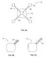
- the rodsmay be arranged so that when they are collapsed, the extensions 14 are disposed adjacent to the carrier portion 12. This may be accomplished by attaching the rods 24 to the center of the carrier portion, as seen in Fig. 5 .
- Hinges(not shown) may further be provided to further collapse the device once the rods are in their collapsed positions.
- Figs. 5B and 5Cillustrate, in a closed position and an open position, respectively, a modification of the device 10 wherein the extensions X4 are attached to the came portion 12 by the use of an accordion arrangement 25.
- the deviceis adapted to be transported easily by a user when not in use. As such, it may be adapted to be folded, as seen in Fig. 1C , to a fully closed position as shown in Fig. 1D .
- a carrying handle 26amay be provided to aid in transport.
- the signal generation and acquisition elements including the antenna array and, optionally, at least a part of signal processing elementsare mounted on the carrier 12 and extensions 14 and covered by a covering 18.
- the coveringwhich is a radome, is substantially transparent at least to signals of the frequency transmitted by the antenna elements.
- Figs. 3A and 3BExamples of arrangements of the antenna array on the carrier portion 12 and the extensions 14 are illustrated in Figs. 3A and 3B .
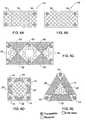
- FIG. 6A through 6Eother arrangements may be used, in consequence with which the geometry of the carrier portion 12 and extensions 14 may be different from that shown in Figs. 1A and 1B . It will be noted that the arrangements and number of the antenna elements shown is for illustrative purposes only. It will be further noted that it is possible according to the present invention to provide a device 10 as seen in Figs. 6A and 6B , wherein there are no areas between the extensions which are free of material of the base.
- Signal generation and acquisition elements of the device 10include, in addition to the antenna array, elements responsible for sampling, synchronization, multiplexing, and pre-processing of the acquired signals.
- Signal processing elementsinclude a processing unit (or units) adapted for the processing signals received from the signal acquisition elements.
- the device 10further includes control units, which may include switches, buttons, dials, and knobs, a power source, a display unit, and any external interfaces, such as connections to external video displays or to external processors.
- control unitswhich may include switches, buttons, dials, and knobs, a power source, a display unit, and any external interfaces, such as connections to external video displays or to external processors.
- the above elements of the deviceare functionally divided into elements constituting its front and back ends, as shown in Fig. 2 .
- front-endand " back-end” are meant to be understood as a division along functional lines.
- the elements associated with either endmay be physically located in separate portions of the device, and parts of one of the ends may be located proximate to parts of the other end (e.g., the display unit may be located among the antenna array, while the other elements of the back-end are located elsewhere).
- the communications means between the front and back-endsmay be accomplished via a wired or wireless connection.
- powermay be transmitted to the front-end from the back-end. This may be via a separate wire, or via the communication line, such as using power over Ethernet or a similar technology.
- the carrier 12carries under the covering 18, part of the antenna array on one side, and a display unit 30 (illustrated in Fig. 1B ) on the other.
- the carrier portion 12houses therewithin all functional elements of the back-end, and a portion of the functional elements of the front-end.
- the remainder of the antenna array 11is housed within the extensions 14. Ribbon wires or any other suitable arrangement may be used to connect the portions of the antenna array carried by the extensions 14 to the portion carried by the carrier portion 12.
- areas 22 between adjacent extensionsmay be free of any material of the base.
- This arrangementcontributes toward easy folding as described above, without a significant adverse effect on the imaging resolution of the device when in the fully open position (i.e., when compared to a reference device of the same size wherein the areas are not free of material of the base).
- the antenna arraybe arranged such that the transmitters are disposed as far as possible from each other, and that for each transmitter, there is a receiver disposed as far away therefrom as possible.
- the aperture of the deviceis thus increased, which increases the resolution thereof, since an object can be imaged from a wider angular view. Therefore, as illustrated in Figs. 3A and 3B , the transmitters 20a are located on the extensions 14, in the corners of the device. By providing areas 22 free of material of the base as described above, this increase in resolution is realized with a lighter and smaller device than would be otherwise.
- the receivers 20bmay be arranged in any desired arrangement, two of which are illustrated schematically in Figs 3A and 3B .
- FIG. 4AA modification of the device described above is shown schematically in Fig. 4A , wherein the extensions 14 are each the same size as the carrier portion 12.
- the extensionsare connected to the carrier portion 12 in such a way so that when the device 10 is folded, the extensions stack upon one another, as illustrated schematically in Fig. 4B .
- any one of a number of contrivancesmay be provided to assist in carrying or supporting the device 10 during use.
- additional handles 26bmay be provided for this purpose.
- Fig. 7Bthere may be provided two inverted-U-shaped arm brackets 28L and 28R.
- a user who wishes to carry to device 10 with his left armwould typically grasp the right bracket 28R with his left hand and allow the left bracket 28L to rest on his left forearm. He may the use his right hand to hold the handle 26a in order to stabilize the device 10 and aid in carrying.
- a user who wishes to carry the device 10 with his right armwould do the reverse.
- a supportgenerally indicated at 32.
- the support 32comprises a belt 34 adapted to be worn by the user, carrying members 36 attached to the belt, and a hub 38.
- a knob 40is provided on a lower edge of the carrier portion 12 of the device 10. The knob 40 is adapted to cooperate for insertion into a notch 42 provided in the top of the hub 38.
- the knob 40may be mounted on a supporting structure 44, which may be a monopod (as in Fig. 9A ), a tripod (as in Fig. 9B ), or a bipod (not shown).
- the monopod and bipodmay be used to aid in stabilization of the device 10, with the handle 26a being used to pivotally move the device, while the tripod may be used in standalone applications.
- the supporting structuremay also be an unmanned or remote-controlled robot (not shown).
- the supporting structuremay be specially equipped to cooperate with the knob 40 for insertion therein, or the knob 40 may be adapted to cooperate with a standard tripod mount for engagement therewith.
- the device 10may further comprise wheels 48 disposed so as to allow for rolling thereof against a flat surface, with the antenna array facing the surface. This is especially useful when the surface is not vertical, such as when imaging through a roof, a floor (in order to image objects in a room below), or other generally horizontal or angles surface.
- Fig. 11One example of a device with such a division is illustrated in Fig. 11 .
- the display unit 30is still housed in the base 13, which comprises all of the elements of the front-end.
- some or all of the other functional elements of the back-end of the above embodimentare housed within a backpack 44.
- Shoulder mounts 46which may be solid or flexible, are provided to carry the backpack, thereby distributing part of the weight of the device 10 to be carried by a user's shoulders.
- This modificationallows for elements of the device which the user does not need direct access to during use to be moved, lightening the base.
- Other examples of this modification(not shown) besides the knapsack illustrated in Fig.
- the base 11include a standalone briefcase-like unit or using a wireless connection to communicate between the base and portions of the backend which may be housed anywhere, such as a van or a laptop computer.
- the basemust include its own power source.
- the portion of the device 10 comprising the front endmay be mounted on a supporting structure 44 such a tripod, and connected via a cable 50 to a portion of the device which comprises the back-end, which may rest on the ground, thereby reducing the weight which is to be born by the supporting structure.
Landscapes
- Remote Sensing (AREA)
- Engineering & Computer Science (AREA)
- Radar, Positioning & Navigation (AREA)
- Physics & Mathematics (AREA)
- General Physics & Mathematics (AREA)
- Computer Networks & Wireless Communication (AREA)
- Electromagnetism (AREA)
- Support Of Aerials (AREA)
- Sewage (AREA)
- Closed-Circuit Television Systems (AREA)
- Ultra Sonic Daignosis Equipment (AREA)
- Investigating Materials By The Use Of Optical Means Adapted For Particular Applications (AREA)
- Geophysics And Detection Of Objects (AREA)
- Burglar Alarm Systems (AREA)
Abstract
Description
- This invention relates to through-wall imaging devices having antenna elements for transmitting and receiving ultra-wideband signals adapted to pass through a wall, and circuitry for processing images of objects behind the wall based on the signals.
- Through-wall imaging is a technology which has many applications, especially those in which decisions are made in extreme or life-threatening situations. Often, advance knowledge of objects behind a wall can salter the decision making process in front of the wall for the better. For example, in lifesaving applications, such as fire rescue situations, pinpointing occupants in a burning building allows rescue personnel to reach them quicker, while avoiding going into other rooms unnecessarily. In law enforcement situations, situational awareness regarding objects behind a wall can favorably influence operational strategy. For example, knowledge of the number and location of suspects or hostages within a room can lead to fewer unwanted casualties in a raid. Such devices may be used for similar purposes by special operation forces or the like.
- Through-wall imaging devices presently known typically comprise an array of antenna elements, some being adapted to transmit, and others being adapted to receive ultra-wideband signals. These devices also comprise a processor to interpret the received signals, and a display unit. They may also be designed so as to facilitate their carrying during imaging.
- "An Ultra-Wideband Through-Wall Radar for Detecting the Motion of People in Real Time", published in The Proceedings of the SPIE, by the SPIE, Bellington, VA, USA, vol. 4744, 2002, pages 48-57, and
US 2002/145570 disclose an antenna array comprising a ground plane and a plurality of elements mounted thereon, the elements being capable of emitting and receiving ultra wideband emissions. Elements are arrayed on the ground plane in two parallel rows, a transmitting row, and a receiving row, such that a given element in the receiving row is aligned in at least one direction with a corresponding element in the transmitting row. Additionally, the elements are configured on the ground plane to elicit a symmetrical product response in the azimuthal plane, and to produce horizontally polarized signals. An alternative embodiment places the elements with unique inter-element spacing within the rows. An embodiment comprises a fence structure between rows. A method for use comprises the step of transmitting a signal via an element in the transmitting row and receiving said signal through an element in the receiving row, not aligned with the transmitting element. - AKELA, Inc. has disclosed, at the 2005 SPIE Defense and Security Syposium, Technologies for Homeland Security and Law, a brassboard imaging wideband imaging radar suitable for portable, fixed in place operation with a maximum range of 100 meters.
EP 1 168 498 discloses a deployable reflecting structure for use in space applications, preferably for RF antenna structures, including at least one rigid section having a reflective surface and at least one bendable section having a reflective surface and being connected to the rigid section. The bendable section is movable between a first, stowed position in which the reflective surface of the bendable section is at least partially overlapping with the reflective surface of the rigid section, and a second, deployed position in which the reflective surfaces are continuous and non-overlapping.JP 10 051215 JP 2002/335113 WO 04/015812 - The present invention is directed to a through-wall imaging device as set out in the appended claims.
- In order to understand the invention and to see how it may be carried out in practice, embodiments will now be described, by way of non-limiting examples only, with reference to the accompanying drawings, in which:
Fig. 1A is a front perspective view of a device according to one embodiment of the present invention in a fully open position;Fig. 1B is a back perspective view of the device illustrated inFig. 1A in a fully open position;Fig. 1C is a front perspective view of the device illustrated inFig. 1A during folding;Fig.1D is a front perspective of the device illustrated inFig. 1A in a fully closed position;Fig. 2 is a block diagram of the functional elements of the device;Figs. 3A and3B are schematic representations of antenna arrays for use with the device illustrated inFig. 1A ;Fig. 4A is a schematic representation of another embodiment of the device;Fig. 4B is a schematic representation of the embodiment illustrated inFig. 4A in a closed position;Figs. 5A through5C are back views of further embodiments of the device;Figs. 6A through6E are schematic representations of still further alternative embodiments of the device;Figs. 7A and7B illustrate modifications of the device illustrated inFig. 1A ;Fig. 8A illustrates the device shown inFig. 1A in cooperation with a support adapted for use therewith;Fig. 8B is a close-up view of a point of connection between the support illustrated inFig. 6A and the device illustrated inFig. 1A ;Figs. 9A and9B illustrate the device illustrated inFig. 1A in cooperation with a free-standing supporting structure;Fig.10 illustrates a further embodiment of the device illustrated inFig. 1A ;Fig. 11 illustrates the device illustrated inFig. 1A according to one modification; andFig. 12 illustrates the device illustrated inFig. 1A according to another modification.Figs. 1A to 1D illustrate a fordable through-wall imaging device, generally indicated at10, in accordance with one embodiment of the present invention, in its operative, open position (Figs. 1A and 1B ) and inoperative closed position (Fig. 1D ). Though not seen inFig. 1A to 1D , the device comprises signal generation and acquisition elements including antenna elements adapted to transmit20a (hereinafter "transmitters") and antenna elements adapted to receive20b (hereinafter "receivers"), constituting an antenna array, for transmitting and receiving ultra-wideband signals adapted to pass through a wall for imaging of objects behind a wall, and signal processing elements, which will later be described in more detail.- As seen in
Figs. 1A to 1D , thedevice 10 comprises a base having acarrier portion 12 andextensions 14 spaced apart from each other. As seen, theextensions 14 are designed and arranged so that their total footprint, when folded, is generally coincident with the carrier portion's12 footprint. Thus, according to the present embodiment, eachextension 14 is square-shaped and is approximately one quarter the size of the carrier portion. - Each extension is articulated by a
corner 15 thereof to acorner 17 of thecarrier portion 12 byhinges 16 to enable folding of thedevice 10, as shown inFigs. 1C . - As illustrated in
Fig. 5A , theextensions 14 may also be attached to thecarrier portion 12 by telescopingrods 24. The rods may be arranged so that when they are collapsed, theextensions 14 are disposed adjacent to thecarrier portion 12. This may be accomplished by attaching therods 24 to the center of the carrier portion, as seen inFig. 5 . Hinges (not shown) may further be provided to further collapse the device once the rods are in their collapsed positions.Figs. 5B and 5C illustrate, in a closed position and an open position, respectively, a modification of thedevice 10 wherein the extensionsX4 are attached to the cameportion 12 by the use of anaccordion arrangement 25. - The device is adapted to be transported easily by a user when not in use. As such, it may be adapted to be folded, as seen in
Fig. 1C , to a fully closed position as shown inFig. 1D . A carryinghandle 26a may be provided to aid in transport. - The signal generation and acquisition elements including the antenna array and, optionally, at least a part of signal processing elements are mounted on the
carrier 12 andextensions 14 and covered by acovering 18. The covering, which is a radome, is substantially transparent at least to signals of the frequency transmitted by the antenna elements. - Examples of arrangements of the antenna array on the
carrier portion 12 and theextensions 14 are illustrated inFigs. 3A and 3B . - As illustrated in
Figs. 6A through 6E , other arrangements may be used, in consequence with which the geometry of thecarrier portion 12 andextensions 14 may be different from that shown inFigs. 1A and 1B . It will be noted that the arrangements and number of the antenna elements shown is for illustrative purposes only. It will be further noted that it is possible according to the present invention to provide adevice 10 as seen inFigs. 6A and 6B , wherein there are no areas between the extensions which are free of material of the base. - Signal generation and acquisition elements of the
device 10 include, in addition to the antenna array, elements responsible for sampling, synchronization, multiplexing, and pre-processing of the acquired signals. - Signal processing elements include a processing unit (or units) adapted for the processing signals received from the signal acquisition elements.
- The
device 10 further includes control units, which may include switches, buttons, dials, and knobs, a power source, a display unit, and any external interfaces, such as connections to external video displays or to external processors. - The above elements of the device are functionally divided into elements constituting its front and back ends, as shown in
Fig. 2 . It should be noted that the terms "front-end" and "back-end" are meant to be understood as a division along functional lines. The elements associated with either end may be physically located in separate portions of the device, and parts of one of the ends may be located proximate to parts of the other end (e.g., the display unit may be located among the antenna array, while the other elements of the back-end are located elsewhere). - The communications means between the front and back-ends may be accomplished via a wired or wireless connection. In addition, power may be transmitted to the front-end from the back-end. This may be via a separate wire, or via the communication line, such as using power over Ethernet or a similar technology.
- Reverting to
Figs. 1A and 1B , thecarrier 12 carries under the covering18, part of the antenna array on one side, and a display unit30 (illustrated inFig. 1B ) on the other. Thecarrier portion 12 houses therewithin all functional elements of the back-end, and a portion of the functional elements of the front-end. The remainder of the antenna array11 is housed within theextensions 14. Ribbon wires or any other suitable arrangement may be used to connect the portions of the antenna array carried by theextensions 14 to the portion carried by thecarrier portion 12. - As seen in
Figs. 1A, 1B ,3A and 3B , in the fully open position,areas 22 between adjacent extensions may be free of any material of the base. This arrangement contributes toward easy folding as described above, without a significant adverse effect on the imaging resolution of the device when in the fully open position (i.e., when compared to a reference device of the same size wherein the areas are not free of material of the base). - As is well known in the art, it is advantageous that the antenna array be arranged such that the transmitters are disposed as far as possible from each other, and that for each transmitter, there is a receiver disposed as far away therefrom as possible. The aperture of the device is thus increased, which increases the resolution thereof, since an object can be imaged from a wider angular view. Therefore, as illustrated in
Figs. 3A and 3B , thetransmitters 20a are located on theextensions 14, in the corners of the device. By providingareas 22 free of material of the base as described above, this increase in resolution is realized with a lighter and smaller device than would be otherwise. - The
receivers 20b may be arranged in any desired arrangement, two of which are illustrated schematically inFigs 3A and 3B . - A modification of the device described above is shown schematically in
Fig.4A , wherein theextensions 14 are each the same size as thecarrier portion 12. The extensions are connected to thecarrier portion 12 in such a way so that when thedevice 10 is folded, the extensions stack upon one another, as illustrated schematically inFig. 4B . - Any one of a number of contrivances may be provided to assist in carrying or supporting the
device 10 during use. As shown inFig. 7A ,additional handles 26b may be provided for this purpose. In addition, as illustrated inFig. 7B , there may be provided two inverted-U-shaped arm brackets device 10 with his left arm, for example, would typically grasp theright bracket 28R with his left hand and allow theleft bracket 28L to rest on his left forearm. He may the use his right hand to hold thehandle 26a in order to stabilize thedevice 10 and aid in carrying. A user who wishes to carry thedevice 10 with his right arm would do the reverse. - In addition, there may be provided elements directed toward stabilization of the device during use. According to an embodiment illustrated in
Fig. 8A , there is further provided a support, generally indicated at32. (It should be noted the illustration inFig. 8A of one extension as being folded is only in order to allow an unhindered representation of the support, and should not be construed as a limitation.) Thesupport 32 comprises abelt 34 adapted to be worn by the user, carryingmembers 36 attached to the belt, and ahub 38. A seen inFig. 8B , aknob 40 is provided on a lower edge of thecarrier portion 12 of thedevice 10. Theknob 40 is adapted to cooperate for insertion into anotch 42 provided in the top of thehub 38. - Alternatively, the
knob 40 may be mounted on a supportingstructure 44, which may be a monopod (as inFig. 9A ), a tripod (as inFig. 9B ), or a bipod (not shown). The monopod and bipod may be used to aid in stabilization of thedevice 10, with thehandle 26a being used to pivotally move the device, while the tripod may be used in standalone applications. The supporting structure may also be an unmanned or remote-controlled robot (not shown). The supporting structure may be specially equipped to cooperate with theknob 40 for insertion therein, or theknob 40 may be adapted to cooperate with a standard tripod mount for engagement therewith. - According to another embodiment, as illustrated in
Fig. 10 , thedevice 10 may further comprisewheels 48 disposed so as to allow for rolling thereof against a flat surface, with the antenna array facing the surface. This is especially useful when the surface is not vertical, such as when imaging through a roof, a floor (in order to image objects in a room below), or other generally horizontal or angles surface. - According to one modification of any of the above embodiments, functional elements of the back-end are physically divided. One example of a device with such a division is illustrated in
Fig. 11 . Thedisplay unit 30 is still housed in the base13, which comprises all of the elements of the front-end. However, some or all of the other functional elements of the back-end of the above embodiment are housed within abackpack 44. Shoulder mounts46, which may be solid or flexible, are provided to carry the backpack, thereby distributing part of the weight of thedevice 10 to be carried by a user's shoulders. This modification allows for elements of the device which the user does not need direct access to during use to be moved, lightening the base. Other examples of this modification (not shown) besides the knapsack illustrated inFig. 11 include a standalone briefcase-like unit or using a wireless connection to communicate between the base and portions of the backend which may be housed anywhere, such as a van or a laptop computer. In the event that a wireless connection is used, the base must include its own power source. As seen inFig. 12 , the portion of thedevice 10 comprising the front end may be mounted on a supportingstructure 44 such a tripod, and connected via acable 50 to a portion of the device which comprises the back-end, which may rest on the ground, thereby reducing the weight which is to be born by the supporting structure. - Those skilled in the art to which this invention pertains will readily appreciate that numerous changes, variations and modifications can be made without departing from the scope of the inventionmutatis mutandis.
Claims (8)
- A through-wall imaging device (10) having antenna elements (20a, 20b) for transmitting and receiving signals adapted to pass through a wall for imaging objects behind the wall, the device comprising a base (13) comprising a carrier portion (12) and a plurality of spaced-apart extensions (14) connected to the carrier portion, at least a portion of said antenna elements being mounted on said extensions, the area (22) between adjacent extensions, which is different from said carrier portion, being free of any material of the base at least when said device is in an open position;characterized in that said extensions are connected to the carrier portion in a manner permitting folding of the extensions onto the carrier portion between a first open position corresponding to an operative state and a second closed position corresponding to an inoperative state.
- A device according to Claim 1, wherein said portion of the antenna elements comprises at least one antenna element, selected from a group comprising an antenna element adapted to transmit said signals and an antenna elements adapted to receive said signals, mounted on at least some of said extensions.
- A device according to Claim 2, wherein said at least one antenna element is adapted to transmit said signals and is mounted at a location on said extensions which is a maximum distance from the carrier portion.
- A device according to any one of the preceding claims, wherein the extensions are sized and articulated such that when they are folded, the footprint of the device are substantially the same size as the footprint of the carrier portion.
- A device according to any one of the preceding claims, wherein the total area of the footprints of the extensions substantially equals the area of the footprint of the carrier portion.
- A device according to any one of the preceding claims, wherein the carrier portion and the extensions are substantially square-shaped, each extension being approximately one quarter the area of the carrier portion and articulated by a corner thereof to a corner of the carrier portion.
- A device according to any one of the preceding claims, wherein each of the extensions arecharacterized by one or more of the hollowing:• they are hingedly articulated to the carrier portion;• they are connected to the carrier portion by telescopically collapsible rods;
and/or• they are connected to the carrier portion by an accordion arrangement. - A device according to any one of the preceding claims, wherein the extensions are detachable from the carrier portion.
Applications Claiming Priority (2)
| Application Number | Priority Date | Filing Date | Title |
|---|---|---|---|
| IL170689AIL170689A (en) | 2005-09-06 | 2005-09-06 | Through-wall imaging device |
| PCT/IL2006/000696WO2007029226A2 (en) | 2005-09-06 | 2006-06-15 | Through-wall imaging device |
Publications (2)
| Publication Number | Publication Date |
|---|---|
| EP1934628A2 EP1934628A2 (en) | 2008-06-25 |
| EP1934628B1true EP1934628B1 (en) | 2010-02-24 |
Family
ID=36954545
Family Applications (1)
| Application Number | Title | Priority Date | Filing Date |
|---|---|---|---|
| EP06745146AActiveEP1934628B1 (en) | 2005-09-06 | 2006-06-15 | Through-wall imaging device |
Country Status (6)
| Country | Link |
|---|---|
| US (1) | US7999722B2 (en) |
| EP (1) | EP1934628B1 (en) |
| AT (1) | ATE459013T1 (en) |
| DE (1) | DE602006012522D1 (en) |
| IL (1) | IL170689A (en) |
| WO (1) | WO2007029226A2 (en) |
Cited By (1)
| Publication number | Priority date | Publication date | Assignee | Title |
|---|---|---|---|---|
| US11747463B2 (en) | 2021-02-25 | 2023-09-05 | Cherish Health, Inc. | Technologies for tracking objects within defined areas |
Families Citing this family (47)
| Publication number | Priority date | Publication date | Assignee | Title |
|---|---|---|---|---|
| US9063232B2 (en)* | 2005-04-14 | 2015-06-23 | L-3 Communications Security And Detection Systems, Inc | Moving-entity detection |
| US8362942B2 (en)* | 2005-04-14 | 2013-01-29 | L-3 Communications Cyterra Corporation | Moving-entity detection |
| US8451162B2 (en)* | 2005-12-20 | 2013-05-28 | Walleye Technologies, Inc. | Microwave datum tool |
| IL187708A (en)* | 2007-11-28 | 2013-04-30 | Camero Tech Ltd | Through-the-obstacle radar system and method of operation |
| US8164507B2 (en)* | 2009-04-21 | 2012-04-24 | Raytheon Company | Fusing multi-sensor data to provide estimates of structures |
| US9229102B1 (en) | 2009-12-18 | 2016-01-05 | L-3 Communications Security And Detection Systems, Inc. | Detection of movable objects |
| EP2513666B1 (en) | 2009-12-18 | 2015-02-18 | L-3 Communications Cyterra Corporation | Moving entity detection |
| US8538167B2 (en)* | 2010-01-07 | 2013-09-17 | Raytheon Company | Designating corridors to provide estimates of structures |
| US8271224B2 (en)* | 2010-01-13 | 2012-09-18 | Raytheon Company | Fusing structures from multi-sensor data |
| US8290741B2 (en) | 2010-01-13 | 2012-10-16 | Raytheon Company | Fusing multi-sensor data sets according to relative geometrical relationships |
| US8593329B2 (en)* | 2010-03-17 | 2013-11-26 | Tialinx, Inc. | Hand-held see-through-the-wall imaging and unexploded ordnance (UXO) detection system |
| KR101191387B1 (en)* | 2010-03-22 | 2012-10-18 | 한국전자통신연구원 | Two dimensional array antenna and object detection device using the same |
| WO2013141923A2 (en)* | 2011-12-20 | 2013-09-26 | Sadar 3D, Inc. | Scanners, targets, and methods for surveying |
| US10754027B2 (en)* | 2012-12-19 | 2020-08-25 | Sony Corporation | Method for generating an image and handheld screening device |
| US10247809B2 (en)* | 2012-12-19 | 2019-04-02 | Sony Corporation | Method for operating a handheld screening device and a handheld screening device |
| EP2933654B1 (en)* | 2014-04-14 | 2017-06-07 | Rohde & Schwarz GmbH & Co. KG | Method and system for millimeter-wave image reconstruction |
| US9575560B2 (en) | 2014-06-03 | 2017-02-21 | Google Inc. | Radar-based gesture-recognition through a wearable device |
| US9811164B2 (en) | 2014-08-07 | 2017-11-07 | Google Inc. | Radar-based gesture sensing and data transmission |
| US9778749B2 (en) | 2014-08-22 | 2017-10-03 | Google Inc. | Occluded gesture recognition |
| US11169988B2 (en) | 2014-08-22 | 2021-11-09 | Google Llc | Radar recognition-aided search |
| US9600080B2 (en) | 2014-10-02 | 2017-03-21 | Google Inc. | Non-line-of-sight radar-based gesture recognition |
| US10016162B1 (en) | 2015-03-23 | 2018-07-10 | Google Llc | In-ear health monitoring |
| CA2981487C (en)* | 2015-04-03 | 2023-09-12 | Evolv Technologies, Inc. | Modular imaging system |
| KR102236958B1 (en) | 2015-04-30 | 2021-04-05 | 구글 엘엘씨 | Rf-based micro-motion tracking for gesture tracking and recognition |
| KR102327044B1 (en) | 2015-04-30 | 2021-11-15 | 구글 엘엘씨 | Type-agnostic rf signal representations |
| US10088908B1 (en) | 2015-05-27 | 2018-10-02 | Google Llc | Gesture detection and interactions |
| US10817065B1 (en) | 2015-10-06 | 2020-10-27 | Google Llc | Gesture recognition using multiple antenna |
| US10564116B2 (en) | 2016-04-28 | 2020-02-18 | Fluke Corporation | Optical image capture with position registration and RF in-wall composite image |
| US10209357B2 (en)* | 2016-04-28 | 2019-02-19 | Fluke Corporation | RF in-wall image registration using position indicating markers |
| US10254398B2 (en) | 2016-04-28 | 2019-04-09 | Fluke Corporation | Manipulation of 3-D RF imagery and on-wall marking of detected structure |
| US10571591B2 (en) | 2016-04-28 | 2020-02-25 | Fluke Corporation | RF in-wall image registration using optically-sensed markers |
| US10585203B2 (en) | 2016-04-28 | 2020-03-10 | Fluke Corporation | RF in-wall image visualization |
| WO2017192167A1 (en) | 2016-05-03 | 2017-11-09 | Google Llc | Connecting an electronic component to an interactive textile |
| WO2017200571A1 (en) | 2016-05-16 | 2017-11-23 | Google Llc | Gesture-based control of a user interface |
| US10302793B2 (en) | 2016-08-04 | 2019-05-28 | Fluke Corporation | Blending and display of RF in wall imagery with data from other sensors |
| US10444344B2 (en) | 2016-12-19 | 2019-10-15 | Fluke Corporation | Optical sensor-based position sensing of a radio frequency imaging device |
| RU2653578C1 (en)* | 2017-06-08 | 2018-05-11 | Акционерное общество "ЛИМАКО" | Radar-location level gage for measuring volume of bulk product in tanks |
| GB2579045A (en)* | 2018-11-15 | 2020-06-10 | Steelrock Tech Ltd | RF antenna platform |
| US11099270B2 (en)* | 2018-12-06 | 2021-08-24 | Lumineye, Inc. | Thermal display with radar overlay |
| US11073610B2 (en) | 2019-01-31 | 2021-07-27 | International Business Machines Corporation | Portable imager |
| US11715228B2 (en) | 2019-04-04 | 2023-08-01 | Battelle Memorial Institute | Imaging systems and related methods including radar imaging with moving arrays or moving targets |
| US11415555B2 (en)* | 2019-07-01 | 2022-08-16 | University Of North Texas | Ultrasonic through-wall sensors |
| EP4004687A1 (en) | 2019-07-26 | 2022-06-01 | Google LLC | Context-sensitive control of radar-based gesture-recognition |
| US11868537B2 (en) | 2019-07-26 | 2024-01-09 | Google Llc | Robust radar-based gesture-recognition by user equipment |
| JP7316383B2 (en) | 2019-07-26 | 2023-07-27 | グーグル エルエルシー | Authentication management via IMU and radar |
| EP3936980B1 (en) | 2019-08-30 | 2024-07-10 | Google LLC | Input methods for mobile devices |
| WO2021040748A1 (en) | 2019-08-30 | 2021-03-04 | Google Llc | Visual indicator for paused radar gestures |
Family Cites Families (14)
| Publication number | Priority date | Publication date | Assignee | Title |
|---|---|---|---|---|
| US5446461A (en)* | 1994-04-28 | 1995-08-29 | Hughes Missile Systems Company | Concrete penetrating imaging radar |
| JPH1051215A (en) | 1996-08-05 | 1998-02-20 | Nippon Telegr & Teleph Corp <Ntt> | Antenna device |
| US5680048A (en) | 1996-08-19 | 1997-10-21 | Net Results, Inc. | Mine detecting device having a housing containing metal detector coils and an antenna |
| US7068211B2 (en) | 2000-02-08 | 2006-06-27 | Cambridge Consultants Limited | Methods and apparatus for obtaining positional information |
| US6624796B1 (en)* | 2000-06-30 | 2003-09-23 | Lockheed Martin Corporation | Semi-rigid bendable reflecting structure |
| US6667724B2 (en) | 2001-02-26 | 2003-12-23 | Time Domain Corporation | Impulse radar antenna array and method |
| JP3971900B2 (en)* | 2001-05-10 | 2007-09-05 | 日本放送協会 | Deployable active phased array antenna, transmitter and receiver |
| JP3952367B2 (en)* | 2001-12-11 | 2007-08-01 | 日本電気株式会社 | Radar equipment |
| US7034749B2 (en)* | 2002-08-07 | 2006-04-25 | Intel Corporation | Antenna system for improving the performance of a short range wireless network |
| US7148836B2 (en)* | 2004-03-05 | 2006-12-12 | The Regents Of The University Of California | Obstacle penetrating dynamic radar imaging system |
| US7307575B2 (en)* | 2004-09-14 | 2007-12-11 | Bae Systems Information And Electronic Systems Integration Inc. | Through-the-wall frequency stepped imaging system utilizing near field multiple antenna positions, clutter rejection and corrections for frequency dependent wall effects |
| US7355545B2 (en)* | 2004-11-02 | 2008-04-08 | Bae Systems Information And Electronic Systems Integration Inc. | Through the wall ranging with triangulation using multiple spaced apart radars |
| US20060061504A1 (en)* | 2004-09-23 | 2006-03-23 | The Regents Of The University Of California | Through wall detection and tracking system |
| US6970128B1 (en)* | 2004-10-06 | 2005-11-29 | Raytheon Company | Motion compensated synthetic aperture imaging system and methods for imaging |
- 2005
- 2005-09-06ILIL170689Apatent/IL170689A/enactiveIP Right Grant
- 2006
- 2006-06-15ATAT06745146Tpatent/ATE459013T1/ennot_activeIP Right Cessation
- 2006-06-15USUS11/991,538patent/US7999722B2/enactiveActive
- 2006-06-15EPEP06745146Apatent/EP1934628B1/enactiveActive
- 2006-06-15DEDE602006012522Tpatent/DE602006012522D1/enactiveActive
- 2006-06-15WOPCT/IL2006/000696patent/WO2007029226A2/enactiveApplication Filing
Cited By (2)
| Publication number | Priority date | Publication date | Assignee | Title |
|---|---|---|---|---|
| US11747463B2 (en) | 2021-02-25 | 2023-09-05 | Cherish Health, Inc. | Technologies for tracking objects within defined areas |
| US12429576B2 (en) | 2021-02-25 | 2025-09-30 | Cherish Health, Inc. | Technologies for tracking objects within defined areas |
Also Published As
| Publication number | Publication date |
|---|---|
| IL170689A0 (en) | 2009-02-11 |
| DE602006012522D1 (en) | 2010-04-08 |
| US7999722B2 (en) | 2011-08-16 |
| EP1934628A2 (en) | 2008-06-25 |
| WO2007029226A3 (en) | 2007-06-21 |
| WO2007029226A2 (en) | 2007-03-15 |
| US20090295618A1 (en) | 2009-12-03 |
| IL170689A (en) | 2011-08-31 |
| ATE459013T1 (en) | 2010-03-15 |
Similar Documents
| Publication | Publication Date | Title |
|---|---|---|
| EP1934628B1 (en) | Through-wall imaging device | |
| KR100959963B1 (en) | Antenna transceiver system | |
| US9843089B2 (en) | Portable antenna | |
| US9316732B1 (en) | Standoff screening apparatus for detection of concealed weapons | |
| US7486235B2 (en) | Antenna system for improving the performance of a short range wireless network | |
| EP3289634B1 (en) | Easily deployable phased antenna for a spacecraft and system of such antennas | |
| US8451180B2 (en) | Integrated antenna and display shade | |
| US9459345B2 (en) | Passive detection of unauthorized electronic devices using wafer scale beam forming | |
| US10826199B2 (en) | Multipolarized vector sensor array antenna system for radio astronomy applications | |
| US10996309B2 (en) | Radiovision device | |
| US12284025B2 (en) | Mobile satellite communication system | |
| US11456799B2 (en) | Portable deployable underground communication systems, devices and methods | |
| CA2149492C (en) | Deployable double-membrane surface antenna | |
| US11990665B2 (en) | Multi-direction deployable antenna | |
| Budianu et al. | Antenna architecture of a nano-satellite for radio astronomy | |
| JP2007033380A (en) | Portable exploration device |
Legal Events
| Date | Code | Title | Description |
|---|---|---|---|
| PUAI | Public reference made under article 153(3) epc to a published international application that has entered the european phase | Free format text:ORIGINAL CODE: 0009012 | |
| 17P | Request for examination filed | Effective date:20080328 | |
| AK | Designated contracting states | Kind code of ref document:A2 Designated state(s):AT BE BG CH CY CZ DE DK EE ES FI FR GB GR HU IE IS IT LI LT LU LV MC NL PL PT RO SE SI SK TR | |
| 17Q | First examination report despatched | Effective date:20080715 | |
| GRAP | Despatch of communication of intention to grant a patent | Free format text:ORIGINAL CODE: EPIDOSNIGR1 | |
| DAX | Request for extension of the european patent (deleted) | ||
| RAP1 | Party data changed (applicant data changed or rights of an application transferred) | Owner name:CAMERO-TECH LTD. | |
| GRAS | Grant fee paid | Free format text:ORIGINAL CODE: EPIDOSNIGR3 | |
| GRAA | (expected) grant | Free format text:ORIGINAL CODE: 0009210 | |
| AK | Designated contracting states | Kind code of ref document:B1 Designated state(s):AT BE BG CH CY CZ DE DK EE ES FI FR GB GR HU IE IS IT LI LT LU LV MC NL PL PT RO SE SI SK TR | |
| REG | Reference to a national code | Ref country code:GB Ref legal event code:FG4D | |
| REG | Reference to a national code | Ref country code:CH Ref legal event code:EP | |
| REG | Reference to a national code | Ref country code:IE Ref legal event code:FG4D | |
| REF | Corresponds to: | Ref document number:602006012522 Country of ref document:DE Date of ref document:20100408 Kind code of ref document:P | |
| REG | Reference to a national code | Ref country code:NL Ref legal event code:VDEP Effective date:20100224 | |
| LTIE | Lt: invalidation of european patent or patent extension | Effective date:20100224 | |
| PG25 | Lapsed in a contracting state [announced via postgrant information from national office to epo] | Ref country code:IS Free format text:LAPSE BECAUSE OF FAILURE TO SUBMIT A TRANSLATION OF THE DESCRIPTION OR TO PAY THE FEE WITHIN THE PRESCRIBED TIME-LIMIT Effective date:20100624 Ref country code:LT Free format text:LAPSE BECAUSE OF FAILURE TO SUBMIT A TRANSLATION OF THE DESCRIPTION OR TO PAY THE FEE WITHIN THE PRESCRIBED TIME-LIMIT Effective date:20100224 Ref country code:PT Free format text:LAPSE BECAUSE OF FAILURE TO SUBMIT A TRANSLATION OF THE DESCRIPTION OR TO PAY THE FEE WITHIN THE PRESCRIBED TIME-LIMIT Effective date:20100625 | |
| PG25 | Lapsed in a contracting state [announced via postgrant information from national office to epo] | Ref country code:AT Free format text:LAPSE BECAUSE OF FAILURE TO SUBMIT A TRANSLATION OF THE DESCRIPTION OR TO PAY THE FEE WITHIN THE PRESCRIBED TIME-LIMIT Effective date:20100224 Ref country code:SI Free format text:LAPSE BECAUSE OF FAILURE TO SUBMIT A TRANSLATION OF THE DESCRIPTION OR TO PAY THE FEE WITHIN THE PRESCRIBED TIME-LIMIT Effective date:20100224 Ref country code:PL Free format text:LAPSE BECAUSE OF FAILURE TO SUBMIT A TRANSLATION OF THE DESCRIPTION OR TO PAY THE FEE WITHIN THE PRESCRIBED TIME-LIMIT Effective date:20100224 Ref country code:FI Free format text:LAPSE BECAUSE OF FAILURE TO SUBMIT A TRANSLATION OF THE DESCRIPTION OR TO PAY THE FEE WITHIN THE PRESCRIBED TIME-LIMIT Effective date:20100224 Ref country code:LV Free format text:LAPSE BECAUSE OF FAILURE TO SUBMIT A TRANSLATION OF THE DESCRIPTION OR TO PAY THE FEE WITHIN THE PRESCRIBED TIME-LIMIT Effective date:20100224 | |
| PG25 | Lapsed in a contracting state [announced via postgrant information from national office to epo] | Ref country code:SE Free format text:LAPSE BECAUSE OF FAILURE TO SUBMIT A TRANSLATION OF THE DESCRIPTION OR TO PAY THE FEE WITHIN THE PRESCRIBED TIME-LIMIT Effective date:20100224 Ref country code:EE Free format text:LAPSE BECAUSE OF FAILURE TO SUBMIT A TRANSLATION OF THE DESCRIPTION OR TO PAY THE FEE WITHIN THE PRESCRIBED TIME-LIMIT Effective date:20100224 Ref country code:CY Free format text:LAPSE BECAUSE OF FAILURE TO SUBMIT A TRANSLATION OF THE DESCRIPTION OR TO PAY THE FEE WITHIN THE PRESCRIBED TIME-LIMIT Effective date:20100224 Ref country code:BE Free format text:LAPSE BECAUSE OF FAILURE TO SUBMIT A TRANSLATION OF THE DESCRIPTION OR TO PAY THE FEE WITHIN THE PRESCRIBED TIME-LIMIT Effective date:20100224 Ref country code:NL Free format text:LAPSE BECAUSE OF FAILURE TO SUBMIT A TRANSLATION OF THE DESCRIPTION OR TO PAY THE FEE WITHIN THE PRESCRIBED TIME-LIMIT Effective date:20100224 Ref country code:RO Free format text:LAPSE BECAUSE OF FAILURE TO SUBMIT A TRANSLATION OF THE DESCRIPTION OR TO PAY THE FEE WITHIN THE PRESCRIBED TIME-LIMIT Effective date:20100224 Ref country code:GR Free format text:LAPSE BECAUSE OF FAILURE TO SUBMIT A TRANSLATION OF THE DESCRIPTION OR TO PAY THE FEE WITHIN THE PRESCRIBED TIME-LIMIT Effective date:20100525 Ref country code:ES Free format text:LAPSE BECAUSE OF FAILURE TO SUBMIT A TRANSLATION OF THE DESCRIPTION OR TO PAY THE FEE WITHIN THE PRESCRIBED TIME-LIMIT Effective date:20100604 | |
| PG25 | Lapsed in a contracting state [announced via postgrant information from national office to epo] | Ref country code:SK Free format text:LAPSE BECAUSE OF FAILURE TO SUBMIT A TRANSLATION OF THE DESCRIPTION OR TO PAY THE FEE WITHIN THE PRESCRIBED TIME-LIMIT Effective date:20100224 Ref country code:BG Free format text:LAPSE BECAUSE OF FAILURE TO SUBMIT A TRANSLATION OF THE DESCRIPTION OR TO PAY THE FEE WITHIN THE PRESCRIBED TIME-LIMIT Effective date:20100524 Ref country code:CZ Free format text:LAPSE BECAUSE OF FAILURE TO SUBMIT A TRANSLATION OF THE DESCRIPTION OR TO PAY THE FEE WITHIN THE PRESCRIBED TIME-LIMIT Effective date:20100224 | |
| PLBE | No opposition filed within time limit | Free format text:ORIGINAL CODE: 0009261 | |
| STAA | Information on the status of an ep patent application or granted ep patent | Free format text:STATUS: NO OPPOSITION FILED WITHIN TIME LIMIT | |
| PG25 | Lapsed in a contracting state [announced via postgrant information from national office to epo] | Ref country code:DK Free format text:LAPSE BECAUSE OF FAILURE TO SUBMIT A TRANSLATION OF THE DESCRIPTION OR TO PAY THE FEE WITHIN THE PRESCRIBED TIME-LIMIT Effective date:20100224 Ref country code:MC Free format text:LAPSE BECAUSE OF NON-PAYMENT OF DUE FEES Effective date:20100630 | |
| REG | Reference to a national code | Ref country code:CH Ref legal event code:PL | |
| 26N | No opposition filed | Effective date:20101125 | |
| PG25 | Lapsed in a contracting state [announced via postgrant information from national office to epo] | Ref country code:IT Free format text:LAPSE BECAUSE OF FAILURE TO SUBMIT A TRANSLATION OF THE DESCRIPTION OR TO PAY THE FEE WITHIN THE PRESCRIBED TIME-LIMIT Effective date:20100224 | |
| PG25 | Lapsed in a contracting state [announced via postgrant information from national office to epo] | Ref country code:CH Free format text:LAPSE BECAUSE OF NON-PAYMENT OF DUE FEES Effective date:20100630 Ref country code:IE Free format text:LAPSE BECAUSE OF NON-PAYMENT OF DUE FEES Effective date:20100615 Ref country code:LI Free format text:LAPSE BECAUSE OF NON-PAYMENT OF DUE FEES Effective date:20100630 | |
| PG25 | Lapsed in a contracting state [announced via postgrant information from national office to epo] | Ref country code:LU Free format text:LAPSE BECAUSE OF NON-PAYMENT OF DUE FEES Effective date:20100615 Ref country code:HU Free format text:LAPSE BECAUSE OF FAILURE TO SUBMIT A TRANSLATION OF THE DESCRIPTION OR TO PAY THE FEE WITHIN THE PRESCRIBED TIME-LIMIT Effective date:20100825 | |
| PG25 | Lapsed in a contracting state [announced via postgrant information from national office to epo] | Ref country code:TR Free format text:LAPSE BECAUSE OF FAILURE TO SUBMIT A TRANSLATION OF THE DESCRIPTION OR TO PAY THE FEE WITHIN THE PRESCRIBED TIME-LIMIT Effective date:20100224 | |
| REG | Reference to a national code | Ref country code:FR Ref legal event code:PLFP Year of fee payment:11 | |
| REG | Reference to a national code | Ref country code:FR Ref legal event code:PLFP Year of fee payment:12 | |
| REG | Reference to a national code | Ref country code:FR Ref legal event code:PLFP Year of fee payment:13 | |
| PGFP | Annual fee paid to national office [announced via postgrant information from national office to epo] | Ref country code:DE Payment date:20250626 Year of fee payment:20 | |
| PGFP | Annual fee paid to national office [announced via postgrant information from national office to epo] | Ref country code:GB Payment date:20250617 Year of fee payment:20 | |
| PGFP | Annual fee paid to national office [announced via postgrant information from national office to epo] | Ref country code:FR Payment date:20250624 Year of fee payment:20 |