EP1932745A2 - Method and apparatus for compensating steering pull - Google Patents
Method and apparatus for compensating steering pullDownload PDFInfo
- Publication number
- EP1932745A2 EP1932745A2EP07121593AEP07121593AEP1932745A2EP 1932745 A2EP1932745 A2EP 1932745A2EP 07121593 AEP07121593 AEP 07121593AEP 07121593 AEP07121593 AEP 07121593AEP 1932745 A2EP1932745 A2EP 1932745A2
- Authority
- EP
- European Patent Office
- Prior art keywords
- signal
- torque
- compensation
- handwheel
- vehicle
- Prior art date
- Legal status (The legal status is an assumption and is not a legal conclusion. Google has not performed a legal analysis and makes no representation as to the accuracy of the status listed.)
- Granted
Links
Images


Classifications
- B—PERFORMING OPERATIONS; TRANSPORTING
- B62—LAND VEHICLES FOR TRAVELLING OTHERWISE THAN ON RAILS
- B62D—MOTOR VEHICLES; TRAILERS
- B62D5/00—Power-assisted or power-driven steering
- B62D5/04—Power-assisted or power-driven steering electrical, e.g. using an electric servo-motor connected to, or forming part of, the steering gear
- B62D5/0457—Power-assisted or power-driven steering electrical, e.g. using an electric servo-motor connected to, or forming part of, the steering gear characterised by control features of the drive means as such
- B62D5/046—Controlling the motor
- B62D5/0472—Controlling the motor for damping vibrations
- B—PERFORMING OPERATIONS; TRANSPORTING
- B62—LAND VEHICLES FOR TRAVELLING OTHERWISE THAN ON RAILS
- B62D—MOTOR VEHICLES; TRAILERS
- B62D6/00—Arrangements for automatically controlling steering depending on driving conditions sensed and responded to, e.g. control circuits
- B62D6/04—Arrangements for automatically controlling steering depending on driving conditions sensed and responded to, e.g. control circuits responsive only to forces disturbing the intended course of the vehicle, e.g. forces acting transversely to the direction of vehicle travel
Definitions
- the present inventionrelates to a method, system, and apparatus for providing enhanced steering pull compensation.
- steering assist torqueis provided by an electric motor coupled to a steering column or shaft.
- a steering wheel or handwheelis also typically coupled to the steering column or shaft in order for a driver to steer the vehicle.
- the handwheelWhen the driver wants to travel substantially straight ahead along a linear path, the handwheel is rotated to a generally centered neutral position which does not cause a change in the direction of travel. However, due to mechanical tolerances and other factors, the handwheel may need to be rotated somewhat away from center to maintain the vehicle's heading along a substantially linear, straight-ahead path.
- the drivermay or may not need to provide any input torque in order to keep the hand-wheel at a neutral position which provides a straight direction of travel, depending on whether there is any torque coming from the steering system that tends to rotate the hand-wheel clockwise or counterclockwise.
- the driverIn situations where the hand-wheel must be pulled slightly in one direction to maintain a substantially straight course, the driver must exert some force to prevent the vehicle from deviating from the intended path.
- This phenomenoncommonly known as "steering pull" can be caused by many factors such as, for example, camber or caster misalignment at the front end, tire properties of ply steer or conicity, air pressure differentials between left and right tires, road surfaces that are not level, crowned pavement, and prevailing wind.
- U.S. Publication No. US2005/0182542describes an electric power steering pull compensation procedure which measures the difference in handwheel angle between the current handwheel angle and what was determined to be a straight-ahead handwheel position using measurements of the handwheel angle acquired over time. The measured difference is provided to an integrator to update a learned long-term correction value towards the currently measured handwheel angle. The long-term correction value is stored in an electronic memory device. A second integrator computes a short-term correction value based on the difference between the current handwheel angle and the stored long-term correction value. The short-term correction value may be reset to an initial value in response to driving conditions such as the steering angle, the speed at which the steering angle changes, and the speed of the vehicle.
- the speed at which the steering angle changeswill increase as the vehicle is driven around a curve.
- the acquisition of short-term and long-term correction valuesmay be enabled, as well as disabled, in response to one or more of the aforementioned driving conditions.
- the long-term and short-term correction valuesare turned into torque commands for an electric motor.
- the actual handwheel anglemay not be reduced to zero in the presence of steering pull. Since a non-zero angle is required to maintain a straight-ahead course heading, this procedure essentially provides open-loop pull compensation based upon measured angle differences.
- a methodis provided to compensation for steering pull in a vehicle steering system that includes a handwheel.
- the methodincludes monitoring the vehicle to determine whether the vehicle is heading forward along a substantially linear straight-ahead path and, if so, measuring handwheel torque, as a sensed torque signal, to determine an amount of steering pull existing at the handwheel.
- the methodalso includes generating a torque assist signal in response to the sensed torque signal and calculating an offset signal for reducing the amount of steering pull to substantially zero.
- the methodfurther includes producing a modified torque assist signal by adding the offset signal to the torque assist signal, and applying the modified torque assist signal to the vehicle steering system.
- a controllerfor a vehicular steering system that includes a handwheel for steering the vehicle, a torque sensing mechanism for sensing torque applied to the handwheel and providing a sensed torque signal in response thereto, an angular position sensor for sensing an angular position of the handwheel and providing an angular position sensor output in response thereto, a vehicle speed sensor capable of acquiring vehicle speed, and a motor which provides assist torque to the steering system.
- the controllerincludes a torque assist function responsive to the sensed torque signal for providing a torque assist command to the motor, and a steering pull compensator for modifying the torque assist command to the motor by an offset signal corresponding to a detected steering pull condition.
- the steering pull compensatorincludes a first lowpass filter operatively coupled to a first integrator for generating a short term compensation signal from the sensed torque signal, a second lowpass filter operatively coupled to the second integrator for generating a long term compensation signal from a modification of the sensed torque signal, and a combiner for combining the short term compensation signal and the long term compensation signal to generate the offset signal.
- the first lowpass filterhas a first time constant
- the second lowpass filterhas a second time constant longer than the first time constant.
- the first integratorhas a first gain
- the second integratorhas a second gain less than the first gain.
- the first and second lowpass filtersare enabled in response to the vehicle traveling forward along a substantially linear straight-ahead path as determined by at least one of the sensed torque signal, the angular position sensor output, and the acquired vehicle speed.
- a system for providing compensation for steering pull in a vehicle steering systemincludes a pull compensation signal generator, a power steering assist motor, and a processing mechanism.
- the processing mechanismcontrols the power steering assist motor through fault and limit logic as a function of the pull compensation signal generator.
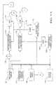
- reference numeral 10generally designates an electric power steering (“EPS") system for a motor vehicle.
- a steering mechanism 12is a rack-and-pinion type mechanism that includes a toothed rack (not shown) and a pinion gear (also not shown) located under a gear housing 14.
- a handwheel 16is coupled to an upper steering shaft 18. As handwheel 16 is turned, upper steering shaft 18, which is connected to a lower steering shaft 20 through a universal joint 22, turns the pinion gear. Rotation of the pinion gear moves the toothed rack, which moves tie-rods 24 (only one shown) that, in turn, move steering knuckles 26 (only one shown), which turn wheels 28 (only one shown).
- EPS assist torqueis provided through an assist unit generally designated by reference numeral 30, which includes a controller 32 and an electric motor 34.
- a motor position commutation sensor 35measures the position of the electric motor 34.
- the controller 32is powered by a vehicular power supply 36 through a supply line 38.
- the controller 32receives a signal indicative of vehicle speed (i.e., vehicle velocity) on signal line 40, which signal may be integrated in order to provide a signal indicative of distance traveled.
- the signal line 40may include other signals indicative of vehicle motion such as a yaw rate, a lateral acceleration, or other vehicle motion signals known in the pertinent art.
- the signals indicative of vehicle motionmay be individual inputs to the controller 32.
- the angular position of handwheel 16is measured by a handwheel angular position sensor 42 and fed to controller 32 through line 44.
- the handwheel angular position sensor 42may be an optical-encoding type of sensor, a variable resistance type of sensor, or any other suitable type of position sensor for performing the functions of an angular position sensor.
- Angular positionrefers to the rotational position of handwheel 16 indicative of a direction in which the vehicle is steered.
- the angular position of the handwheel 16 as measured by the handwheel angular position sensor 42is referred to herein, it will be understood that any equivalent signal combination may be used to determine a vehicle column/pinion shaft position within the scope of the disclosed invention.
- a motor position sensor, a column position sensor, or a rack position sensormay be substituted for the handwheel angular position sensor 42 in exemplary embodiments further detailed herein.
- handwheel torque sensing mechanism 43senses a torque (i.e., twisting force) applied to handwheel 16 by a vehicle operator.
- Handwheel torque sensing mechanism 43may include a torsion bar (not shown) and a variable-resistance type of sensor (also not shown) that outputs a signal to controller 32 through line 46 in relation to an amount of twist present on the torsion bar.
- Other suitable torque sensing devices used with known signal processing techniqueswill suffice in alternate embodiments.
- controller 32In response to inputs on any of lines 40, 44 and 46, controller 32 sends a command signal through line 48 to electric motor 34.
- electric motor 34supplies torque assist to the steering system through a worm 47 and a worm gear 49, so as to provide a steering torque assist to the vehicular steering system in addition to any steering force exerted by the vehicle operator.
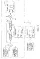
- an EPS control algorithmis indicated generally by the reference numeral 50, which algorithm is implemented by the controller 32 of FIG. 1 .
- the EPS control algorithm 50includes a steering pull compensator 52.
- the EPS control algorithm 50receives a signal indicative of the torque applied to the pinion gear at a non-inverting input of a summing function 54, which generates an applied torque signal indicative of the torque applied to handwheel 16 ( FIG. 1 ) by a vehicle operator.
- a torque assist function 56 depicted as "electronic power steering" as known to those of ordinary skill in the pertinent art,receives the applied torque signal and produces a signal indicative of the desired assist torque.
- a summing function 58receives the assist torque signal at a non-inverting input, and generates a signal to be subtracted from the pinion torque at an inverting input of summing function 54.
- the steering pull compensator 52receives the applied torque signal at a filter 60, which also receives a condition flag from an enable criteria block 62.
- the filter 60provides a filtered version of the applied torque signal to an integrator 70.
- the output from the integrator 70is limited by a limit function 76.
- the limited valuemay be stored in an electronic control unit (ECU) storage 74.
- the stored valuemay be used to initialize the integrator 70 at the next ignition cycle.
- the ECU storage 74may also hold other configuration parameters and filter coefficents.
- the output from limit function 76is received at a non-inverting input of summing function 58.
- the handwheel torque felt by the driveris determined by torque assist function 56 and summing function 54, where the assist torque is provided as a function of the torque applied at handwheel 16 ( FIG. 1 ).
- the driver torque due to the pull compensation schemeis affected by steering pull compensator 52 ( FIG. 2 ) in combination with summing function 58.
- a combination of vehicle signals received at enable criteria block 62are used to determine if the vehicle is being driven forward along a substantially linear, straight-ahead path. This information is used to conditionally filter the torque applied by the driver at filter 60. If the enable criteria block 62 produces a TRUE output indicating that the vehicle is being driven along a substantially linear, straight-ahead path, then the torque is filtered. If the enable criteria block 62 produces a FALSE output, then the filter value is held to the last value.
- the output from the filter 60is presented to the integrator 70 which functions to integrate, with a calibrated gain, the filtered value toward zero.
- the integrator 70could instead be a constant increment or quantizer, a proportional increment, or any other form of increment suitable to meet design criteria.
- a calibrated valuemay be used such that no increment and no compensation are applied if the measured torque is below a certain threshold. If the enable criteria block 62 produces a FALSE output, the input to integrator 70 is set to zero. So while no new learning will take place, the previously learned compensation is still applied.
- the limit function 76uses a calibrated value to prevent the pull compensation from exceeding a desired or predetermined value. The algorithm continues to reduce the pull torque in handwheel 16 ( FIG. 1 ) until the value of the torque reaches zero or a calibrated threshold.
- the calculated pull compensationmay be implemented in several alternate ways, such as, for example, by continuous compensation performed in real time, by compensation added at beginning of each of a plurality of ignition cycles based on values computed in one or more preceding cycles, by compensation added at the beginning of an ignition cycle after a pull condition has been detected over multiple ignition cycles with additions to be made to the shown configuration to account for storage and selection of multiple values, or by compensation having a compensation value that can be accessed during vehicle service provided by writing an offset to a memory location.
- Each ignition cyclecomprises activating an ignition mechanism to start the vehicle, driving the vehicle, and then switching the vehicle off.
- Steering pull compensator 52accepts applied steering handwheel torque as one of its inputs and produces a compensating torque command to be added to the regular steering assist command.
- the compensating processstarts by determining the existence of a residual torque at the steering handwheel 16 caused by pull.
- the controller 32determines that the steering handwheel torque is most likely an undesirable residual torque while the driver intends to drive in a forward direction along a substantially linear straight-ahead path
- the EPS control algorithm 50adds torque as calculated by the steering pull compensator 52 to the torque assist function 56 so that the driver no longer has to provide the torque.
- a drivermay take her hands off the handwheel 16, with the vehicle continuing to travel along the substantially linear straight-ahead path without further driver intervention.
- the compensating torque value calculated by the steering pull compensator 52may be stored to a memory location in the ECU storage 74 which can be reset at vehicle assembly or upon mechanical service being performed to correct the steering pull condition.
- FIGs. 3A-3Ctogether comprise a flowchart setting forth a method of providing steering pull compensation according to a first set of embodiments disclosed herein.
- the methodcommences at block 301 where at least one of torque applied to handwheel 16 ( FIG. 1 ), handwheel angular position, or vehicle speed are monitored. Additionally or alternatively, throughout FIGs. 3A-3C , it is possible to monitor any of handwheel velocity, vehicle acceleration, yaw rate, lateral acceleration, wheel speeds, or delta wheel speeds, which may assist in determining whether a vehicle is heading forward on substantially linear straight-ahead path.
- FIG. 3A , block 302based upon monitoring of handwheel angular position, a range of handwheel angles is defined.
- This rangeis estimated to include a handwheel angle corresponding to a substantially linear straight-ahead vehicle path.
- the range of handwheel anglesis not centered at a zero angular position. This zero angular position is defined as an angular position wherein the handwheel is not turned substantially to the left or to the right.
- a testis performed to ascertain whether or not the current handwheel angular position is within the range of handwheel angles defined in the immediately preceding block. If not, the program loops back to block 301.
- Optional blocks 302 and 303are intended to address situations where it may be desirable to limit the range of handwheel angle measurements that will be considered driving along a substantially linear, straight-ahead path. Nonetheless, a sufficiently broad range should be utilized so as to enable detection of steering pull conditions which, by definition, are not centered at zero. Accordingly, a conditional filter may be applied to handwheel angular position such that, during conditions of low handwheel torque and high vehicle speed, the handwheel angular position data are monitored and slowly filtered. The filtered result would then be a good choice for where to center the allowable handwheel range to enable steering pull compensation.
- a given vehiclemay require 15 degrees of handwheel angle to the left of a straight-ahead angular position in order to hold a 2 Nm pull condition to guide the vehicle along a substantially linear, straight-ahead path.
- a handwheel angular positionenable criteria range centered at zero, a range of 20 degrees might then be required in order to reliably detect the pull condition and compensate for it.
- a 20-degree rangeis a rather large range which might compromise performance under a variety of conditions.
- the algorithm of FIGs. 3A-3Cis allowed to adjust for this 15-degree offset, a range of only plus and minus 5 degrees might then be needed to adequately detect and compensate for the aforementioned 2 Nm of steering pull.
- optional block 304a validity check is performed.
- the validity of at least one of (a) monitored torque applied to the handwheel, (b) monitored handwheel angular position, or (c) monitored vehicle speed,is tested.
- the testis performed using at least one of (1) vehicle status information, or (2) a limit test defining allowable limits for monitored torque, handwheel angular position, and/or vehicle speed.
- a testis performed at optional block 305 to determine whether or not any of (a) monitored torque applied to the handwheel, (b) monitored handwheel angular position, or (c) monitored vehicle speed, are invalid based upon a limit test or vehicle status information.
- the pull compensation algorithm of FIGs. 3A-3Cshould not be enabled because it might otherwise learn corrections during driving maneuvers which were not essentially straight-ahead driving. Similar considerations apply to handwheel angular position and applied handwheel torque. Pursuant to an alternate embodiment, if other vehicle sensor signals are valid, an invalid handwheel angle or vehicle speed is tolerated. For instance, if the torque applied to the handwheel as monitored by a handwheel torque sensing mechanism is valid, then subsequent operations as set forth in the pull compensation algorithm of FIGs. 3A-3C may be enabled by following the negative branch from block 305 (indicating failure to find an invalid value). The affirmative branch from block 305 (indicating success at finding at least one invalid value), leads back to block 301.
- block 306is performed immediately after block 301 if optional blocks 302-305 are not to be performed.
- a testis performed to ascertain whether or not the vehicle is traveling along a substantially linear, straight-ahead path based upon monitoring at least one of torque applied to the handwheel, handwheel angular position, or vehicle speed. If not, the program loops back to block 301.
- a torque sensing mechanismsenses torque applied to the handwheel by generating a sensed torque signal in response to applied torque.
- the sensed torque signalis then filtered (block 309) using a lowpass filter having a first time constant.
- the filtered sensed torque signal from the first lowpass filteris integrated using a first integrator, to thereby generate a short term estimate of required steering pull compensation (block 311).
- a modified sensed torque signalis filtered using a second lowpass filter having a time constant longer than the first time constant (block 313).
- the filtered modified sensed torque signal from the second lowpass filteris integrated using a second integrator to thereby generate a long term estimate of required steering pull compensation (block 315).
- the short term estimate and the long term estimateare combined to generate a pull compensation signal for application to a torque assist motor such as electric motor 34 ( FIG. 1 ).
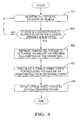
- FIG. 4is a flowchart setting forth a method of providing steering pull compensation according to a second set of embodiments disclosed herein.
- the methodprovides compensation for steering pull in a vehicle steering system that includes a handwheel.
- the methodincludes monitoring one or more sensors on the vehicle.
- a testis performed to determine whether or not the vehicle is heading forward along a substantially linear straight-ahead path based upon the sensor monitoring of block 401. If not, the program loops back to block 401.
- the affirmative branch from block 403leads to block 405 where handwheel torque is measured to determine an amount of steering pull existing at the handwheel.
- a torque assist forceis calculated for reducing the amount of steering pull to substantially zero (block 407). This torque assist force is applied to the vehicle steering system (block 409).
- FIGs. 5A and 5Btogether comprise a block diagram of a system for providing steering pull compensation according to a third set of embodiments disclosed herein.
- the systemincludes one or more vehicle inputs such as a handwheel torque 101, a handwheel angular position 105, a vehicle speed 109, and an optional vehicle status 113.
- the handwheel torque 101may be derived from the handwheel torque sensing mechanism 43 ( FIG. 1 ).
- the angular position of handwheel 16 ( FIG. 1 )is measured by handwheel angular position sensor 42 ( FIG. 1 ) and may be converted into the handwheel angular position 105.
- the handwheel angular position 105may be a scaled value derived from the relationship between the motor position commutation sensor 35 ( FIG. 1 ) and the handwheel angular position sensor 42 ( FIG. 1 ).
- Angular positionrefers to the rotational position of handwheel 16 ( FIG. 1 ) indicative of a direction in which the vehicle is steered.
- the illustrative configuration of FIG. 5Autilizes a vehicle speed 109 and a vehicle status 113.
- the vehicle speed 109may be determined using any device or combination of devices that are capable of detecting, determining, or outputting vehicle speed on signal line 40 ( FIG. 1 ).
- the vehicle speed 109is derived from the vehicle of FIG. 1 .
- vehicle speed informationis determined by a speedometer, an onboard computer, or both, and subsequently outputted on a communications bus.
- Other signals indicative of vehicle motionmay be available through signal line 40 as well, such as handwheel velocity, vehicle acceleration, yaw rate, lateral acceleration, wheel speeds, or delta wheel speeds.
- Vehicle status 113may be implemented using any device or combination of devices that are capable of detecting one or more operational faults or diagnostic conditions with respect to the vehicle.
- vehicle status 113is implemented using an on-board vehicle computing device compliant with on board diagnostic (OBD-II) standards and capable of outputting one or more detected trouble codes (DTCs) in the event a fault condition is detected.
- OBD-IIon board diagnostic
- the handwheel torque 101in the form of a sensed torque signal, is fed to a first input of a first summer 135, and also to an input of a first conditional lowpass filter 121.
- the output of first summer 135is fed to an input of a second conditional lowpass filter 119.
- First conditional lowpass filter 121is enabled by a short term enable logic circuit 123 operatively coupled to a timer 133.
- Second conditional lowpass filter 119is enabled by a long term enable logic circuit 125 operatively coupled to a timer 131.
- the output of first conditional lowpass filter 121is processed by a limit 129, and the output of second conditional lowpass filter 119 is processed by a limit 127.
- Limit 127 and limit 129pass signals that fall within an allowable range of signal values, or pass signals that fall below a predetermined threshold, or both.
- the selection of the limitmay be based on the magnitude of pull desired to compensate and/or to achieve a desired initial timing response.
- limit 127 and limit 129fail to pass signals that do not fall within the allowable range of signal values, or fail to pass signals that do not fall below the predetermined threshold, or both.
- the output of limit 129is fed to a first integrator 147, and the output of limit 127 is fed to a second integrator 163.
- the first integrator 147may include a short term anti-windup limit (not shown).
- the second integrator 163may include a long term anti-windup limit (not shown).
- Both the first and second integrators 147 and 163may support initialization of past value parameters to either a zero value or a stored value.
- a past value parameter in the first integrator 147is initialized to a zero value on ignition, a reset or other initialization event, while a past value parameter in the second integrator 163 is initialized to a stored value on ignition or other initialization event.
- a short-term pathis defined as including first conditional lowpass filter 121 and a first integrator 147.
- a long-term pathis defined as including second conditional lowpass filter 119 and a second integrator 163.
- the short-term pathoperates continuously in real time.
- the short term pathis not dependent upon the operation of the long term path; therefore, short term compensation can be enabled before long term compensation is enabled.
- First conditional lowpass filter 121 utilized in the short term pathprovides a relatively fast time constant which, in one illustrative embodiment, is approximately 0.035 Hz. If straight-ahead conditions are met, indicating that the vehicle is driving along a substantially linear, straight-ahead path as determined by one or more vehicle sensors operatively coupled to short term enable logic circuit 123, the sensed torque signal is filtered.
- first conditional lowpass filter 121also termed “short term bias”
- the short term biasis fed to the first integrator 147. If the straight-ahead conditions are met, the short term bias is integrated; otherwise, the input to first integrator 147 is set to zero and the output of first integrator 147 remains unchanged.
- the integrator state variablemay also be reset or ramped to zero if a steering event is recognized, such as a change in vehicle heading. This is to avoid an unlearning phase due to changing vehicle heading on a windy day, or when turning off from a crowned road, for example.
- the short term integrator stateis never stored upon vehicle shutdown wherein the vehicle ignition switch is moved to an off position. There is an additional comparison of the short term bias to a predefined minimum handwheel torque value.
- the short term biasis not integrated by first integrator 147. This allows the ability to specify steering pull compensation only down to some predetermined minimum level of pull as, for example, 0.25 Nm. Further compensation below this minimum level may be undesirable due to possible error in readings acquired by handwheel torque sensing mechanism 43 ( FIG. 1 ) or simply to avoid continually chasing the last few counts of error.
- this minimum handwheel torque valueis set to zero, and the apparatus of FIGs. 5A-5B attempts to compensate for any nonzero bias presented to first integrator 147.
- first integrator 147is fed to a weighted gain 143 selected to achieve a desired response time, along with the previously selected time constant of first conditional lowpass filter 121.
- a gain of 0.054is employed along with a sampling time of 0.002 seconds to achieve performance of learning 1 Nm of short term bias in approximately 25 seconds.
- other techniquescould be used, such as a constant increment, an increment proportional to short term bias, a variable integration gain, or the like.
- the long-term pathis defined as including second conditional lowpass filter 119 and second integrator 163.
- the long-term pathmay operate in continuous time or across multiple ignition cycles.
- An ignition cycleis defined as starting the vehicle by activating the ignition switch, driving the vehicle, and deactivating the vehicle by switching the ignition switch to an off position.
- the long term pathis not reset during driving events, and the weighted or unweighted output of second integrator 163 is stored upon vehicle shutdown (switching the ignition switch to an off position). This stored value is only zeroed out (i.e., using a serial message on the vehicle communications bus) if the vehicle was serviced to repair the steering pull problem itself.
- a continuous time approachis similar to the short term path, but with a longer filter time constant for second conditional lowpass filter 119 (illustratively, a cutoff frequency of approximately 0.001 Hz) and a smaller integrator gain (illustratively, 0.0015), along with a sampling time of approximately 0.064 seconds in an illustrative embodiment.
- the foregoing illustrative valuesachieve the performance of learning 1 Nm of long term bias in approximately 15 minutes.
- the short term correctionis quickly learned whether or not the bias is due to crowned roads, gusts of wind, or vehicle chassis issues. This is advantageous in that the vehicle driver need not wait a long time to compensate even for a long term chassis problem.
- this correctionshould be moved from the short term path to the long term path. This would allow the correction to be stored upon vehicle shutdown. Then the long term path would be initialized to this value at the next ignition cycle, and the correction would not have to be relearned. In this manner, a true, long term chassis offset is learned over time and not relearned during each ignition cycle. This is appropriate because a true long term chassis offset would be present during each ignition cycle.
- corrections for crowned roads or cross windsare temporary in nature. Corrections for temporary conditions should be relearned during each ignition cycle, and possibly also relearned after detection of a steering event (i.e., turning the vehicle through a 90-degree turn).
- the first integrator 147may include a short term anti-windup limit
- the second integrator 163may include a long term anti-windup limit.
- Anti-windup limitsprevent the output of, respectively, first integrator 147 and second integrator 163, from growing too large over time due to a small persistent error at the integrator input.
- This anti-windup limitcould be set to a somewhat higher value than the allowed range of steering pull compensation, and then used for diagnostic purposes. If the learned correction grew too much larger than the allowed correction, a service lamp or check engine indicator may be illuminated to recommend vehicle service, and/or in OBD-II compliant vehicles, a newly defined DTC trouble code may be set.
- the anti-windup limitis selected to not exceed the desired correction for, respectively, the short term path and the long term path.
- the integrator outputis then not allowed to exceed the desired correction term.
- a vehicle manufacturermay wish to limit maximum permissible pull compensation to no greater than a predetermined value, for example 1 Nm. This will avoid masking a true vehicle problem which should be serviced. If the limit is sufficiently low (3 Nm for example), it would not be considered a safety critical contribution to the overall steering command executed by electric motor 34 ( FIG. 1 ). If the overall compensation is desired to be limited to, say, 1 Nm, the long term path may also be limited to 1 Nm. This would allow the full compensation to eventually be moved to the stored long term path if the pull were a long term phenomenon.
- the short term pathmay also be limited to 1 Nm, or possibly up to 2 Nm. Leaving both long term and short term paths limited to the same value allows only up to that maximum correction in either path. Having a larger range on the short term path allows a full, say, 1 Nm output correction for a crowned road or a wind condition even for a vehicle that is fully long term compensated in the absence of these temporary conditions.
- first integrator 147for the short term path
- the output of first integrator 147will be larger than its current contribution.
- each pathis limited to 1 Nm
- the overall correctionis limited to 1 Nm.
- the short term correctionmay be 0.75 Nm and the long term correction may be 0.75 Nm.
- the sumis 1.5 Nm, but since this sum constitutes the overall correction, it is limited to 1.0 Nm.
- driving conditionsmay change, requiring the short term correction to decrease (i.e., the crowned road becomes flat with no change in vehicle heading). So the short term correction begins to move from 0.75 Nm towards 0 Nm. But there is no immediate effect on the output because the output was already limited to 1 Nm.
- the short term correctionwould have to drop below 0.25 Nm before the effect of the correction is felt by a driver of the vehicle. Accordingly, in this example, the ability of the short term path to quickly assess and react to changed road conditions is not effectively utilized. While the amount of time it takes to lower the short term path output to 0.25 Nm is not long, it is nonetheless an unnecessary wait.
- the anti-windup limit for short term anti-windup limitcan be decreased to the lower value (0.25 Nm) so that the time it takes to unlearn upon cessation of a temporary driving condition is reduced or eliminated.
- the short term anti-windup limitmay be advantageously lowered to the equivalent of the actual short term contribution.
- first integrator 147representing a short term path correction
- second integrator 163representing a long term path correction
- Each weighted gain 143, 157may employ a weighting function to weight a respective short term or long term path correction by a value from 0 to 1.
- Each pathmay employ an individual limit, but this is not necessary if the anti-windup limits are selected according to the desired ranges discussed previously.
- the short term path, the long term path, or both pathsmay be scaled as a function of vehicle speed. This allows compensation to be ramped down to zero at zero vehicle speed since it is not necessary to compensate for a steering pull condition when the vehicle is at rest.
- Weighted gains 143, 157could also be used to apply a desired compensation in each of one or more vehicle speed ranges. This feature would be useful if it could be determined how likely pull conditions would behave versus vehicle speed for a given vehicle.
- Such blending with vehicle speedcould be performed after the outputs of weighted gains 143 and 157 are summed by a second summer 155.
- blending with vehicle speedcould be performed individually on the short term path and the long term path so that the short term path contribution can be effectively known for computing an appropriate input to the long term path as described previously.
- the short term and long term path correctionsare determined with all associated scaling and limits applied at scaled gain 149, weighted gain 143, and weighted gain 157. These two contributions, from the long term and short term paths, are summed into a pull compensation offset signal 153 by second summer 155.
- Limit 151limits the value of pull compensation offset signal to the allowed compensation value discussed previously.
- Pull compensation offset signal 153is summed with an electric power steering torque command for application to electric motor 34 ( FIG. 1 ).
- an unlimited pull compensation offset signal at the output of second summer 155(or an unlimited pull compensation signal computed independently) would be compared to the limited pull compensation offset signal 153 at the output of limit 151.
- a fault indicator or check engine lampmay be illuminated, or pull compensation offset signal 153 gradually reduced towards zero, or the current pull compensation offset signal 153 simply held to its present value indefinitely. Any of these conditions would eventually alert the driver to service their vehicle. Any stored long term value would be reset to zero during this service.
- the short term path shown in FIGs. 5A-5Bis utilized, and the long term path is eliminated or not used. Since the short term path quickly learns corrections even for chassis issues, it could be used exclusively to compensate for both short term conditions (crowned roads, cross winds), and long term conditions (vehicle chassis issues).
- the short term path correctioncould, but need not, be stored over multiple ignition cycles. However, if the correction is not stored over multiple ignition cycles, this would eliminate the need to reset the long term path correction after the vehicle is serviced. If satisfactory performance is achieved simply via the short term path, and the learning time is sufficiently short, this alternate embodiment is a viable option.
- steering pull compensationis driver selectable. Under these circumstances, steering pull compensation may be automatically disabled at ignition on. The feature would be enabled, for example, by pressing a momentary contact, spring loaded, or rocker switch which, when pressed, causes visual feedback to be provided in the form of an indicator lamp.
- the steering compensation system shown in FIGs. 5A and 5Bmay be configured so that the driver can enable or disable the entire compensation function, or merely just enable or disable the short term path or the long term path correction. If the driver disabled the entire compensation function, re-enabling the function may or may not cause the learned long term path correction to be reset to zero, depending upon customer requirements.
- re-enablingdoes reset the learned long term path correction to zero, it would eliminate the need for special service procedures to reset the long term path correction via a serial message on the vehicle communications bus.
- Another approach to eliminating the need for special service proceduresis to have a driver-initiated sequence of events reset the long term path correction. For example, resetting the long term path correction could be performed in response to the driver resetting a change oil indicator on the vehicle.
- FIG. 6is a block diagram of a system for providing steering pull compensation according to a fourth set of embodiments disclosed herein.
- This approachseparates a sensed torque signal based upon frequency components contained within the signal.
- the sensed torque signalis provided by the handwheel torque 101 as derived from handwheel torque sensing mechanism 43 ( FIG. 1 ).
- the sensed torque signalis fed to an input of a slow lowpass filter 221 which conditionally filters the signal based upon one or more conditions sensed by handwheel torque sensing mechanism 43 ( FIG. 1 ), the handwheel angular position 105, vehicle speed 109, and/or vehicle status 113.
- These one or more sensed conditionsare processed by an enable criteria logic circuit 223 which enables slow lowpass filter 221, a fast lowpass filter 219, a fast integrator 227, and a slow integrator 229, when the one or more sensed conditions are indicative of the vehicle proceeding forward along a substantially linear, straight-ahead path.
- Slow lowpass filter 221is designed to have a cutoff frequency sufficient for separating long term (lower frequency) phenomena from the sensed torque signal.
- the output of slow lowpass filter 221, representing handwheel torque in a lower frequency range,is presented to slow integrator 229 which has the effect of correcting or adjusting the output of slow lowpass filter 221 over time. More specifically, any nonzero value in this low frequency range is integrated to compute a long term correction.
- the total handwheel torque, less the low frequency filtered output,is a remaining component of driver-applied handwheel torque which has yet to be examined for correction.
- This remaining componentdeveloped by subtracting the output of the slow lowpass filter 221 from the sensed torque signal at a first summer 235, is fed to an input of fast lowpass filter 219.
- Fast lowpass filter 219filters the remaining component if, as discussed previously, the fast lowpass filter is enabled by enable criteria logic circuitry 223.
- a cutoff frequency for fast lowpass filter 219is selected which is higher than the cutoff frequency of slow lowpass filter 221.
- the cutoff frequency of fast lowpass filter 219is chosen to include short term steering pull contributions such as transitioning to a crowned road or experiencing a cross wind.
- the output of fast lowpass filter 219is presented to slow integrator 229 for possible correction or further refinement.
- Fast lowpass filter 219 and fast integrator 227form a short term path which generates an output in the form of a short term correction.
- This short term correctionis independent of a long term correction generated by a long term path that includes slow lowpass filter 221 and slow integrator 229.
- a second summer 237sums the long term correction generated at the output of slow integrator 229 with the short term correction generated at the output of fast integrator 227.
- the output of second summer 237represents a total correction.
- the output of second summer 237may be fed to a limit 241 for limiting the total correction to a predetermined range, or for limiting the magnitude of the total correction to less than a predetermined threshold.
- a limit 241for limiting the total correction to a predetermined range, or for limiting the magnitude of the total correction to less than a predetermined threshold.
- FIGs. 7A and 7Btogether comprise a block diagram of a system for providing steering pull compensation according to a fifth set of embodiments disclosed herein.
- the system depicted in FIGs. 7A and 7Bare an alternate embodiment similar to FIGs. 5A and 5B , but with improved computational efficiency.
- the systemenables computation of both a short term and a long term contribution in a single path.
- the short term pathis similar to that previously described in FIGs. 5A and 5B .
- the system of FIGs. 7A and 7Bincludes one or more vehicle inputs such as a handwheel torque 101, a handwheel angular position 105, a vehicle speed 109, and an optional vehicle status 113.
- the handwheel torque 101in the form of a sensed torque signal, is an input to a first conditional lowpass filter 721.
- the first conditional lowpass filter 721is enabled by a short term enable logic circuit 723 operatively coupled to a timer 733.
- a second conditional lowpass filter 719is enabled by a long term enable logic circuit 725 operatively coupled to a timer 731.
- the output of first conditional lowpass filter 721is processed by a limit 729, and the output of second conditional lowpass filter 719 is processed by a change limit 727.
- Limit 729passes signals that fall within an allowable range of signal values, or pass signals that fall below a predetermined threshold, or both. Similarly, limit 729 fails to pass signals that do not fall within the allowable range of signal values, or fail to pass signals that do not fall below the predetermined threshold, or both.
- the change limit 727restricts filtered long term pull compensation values into step size change effect increments.
- the step size change effect incrementsmay be stored in ECU storage 74 either directly or incrementally by adding the step size change effect increments to the previously stored past value.
- the output of limit 729is fed to an integrator 747, which may include a short term anti-windup limit (not shown).
- the integrator 747supports initialization of past value parameters to either a zero value or a stored value.
- a past value parameter in the integrator 747is initialized to the stored long term limited calculation value on a reset or other initialization event.
- the output of the integrator 747is fed to a weighted gain 743 selected to achieve a desired response time, along with the previously selected time constant of first conditional lowpass filter 721. It should be noted that, while the exemplary embodiment disclosed herein employs the integrator 747, other techniques could be used, such as a constant increment, an increment proportional to short term bias, a variable integration gain, or the like.
- the output of the integrator 747, representing a short term path correctionis scaled into output torque units to be applied to electric motor 34 ( FIG. 1 ) using the weighted gain 743 ( FIG. 7B ).
- the weighted gain 743may employ a weighting function to weight a respective short term path correction by a value from 0 to 1.
- the short term pathmay be scaled as a function of vehicle speed.
- a limit 751limits the value of the weighted gain 743 that is output as a pull compensation offset signal 753.
- a short term calculationpersists over time, it can be learned as a long term contribution by putting the short term calculation through a slow low pass filter, i.e. the second conditional lowpass filter 719.
- the output of the weighted gain 743may be fed to the second conditional lowpass filter 719 to produce a long term contribution.
- the long term contributionis not used to directly produce a pull compensation offset signal 753; rather, the long term contribution is stored in non-volatile memory, such as ECU storage 74.
- the long term contribution valuemay be limited in magnitude per ignition cycle to achieve further robustness through the change limit 727. This helps ensure that only true long term effects will be stored by storing only a small step toward the desired value.
- the allowed changemay be unlimited in step size for a non-robust, more responsive design.
- the short term pathis initialized to the stored value long term value at the start of the next ignition cycle. If a short term reset is required, it may be reset to the long term value, instead of reset to zero.
- exemplary embodiments depicted in FIGs. 7A and 7Bprovide the essential functionality of the embodiments depicted in FIGs. 5A and 5B , with lower computational complexity.
- FIG. 8is a graphical representation of voltage as a function of torque for an illustrative implementation of handwheel torque sensing mechanism 43 depicted in FIG. 1 , and used in FIGs. 2 , 5A , 6 , and 7A .
- the graphical representation of FIG. 8is presented only for purposes of illustration, as those having ordinary skill in the relevant art will appreciate that any of various structures, devices, or configurations may be utilized to implement torque sensing mechanism 43, and such structures, devices, or configurations may or may not provide outputs as shown in FIG. 8 .
- handwheel torque sensing mechanismgenerates two voltage outputs denoted as T1 and T2.
- Torqueshown along the X axis, is 0 Nm when handwheel 16 ( FIG. 1 ) is at rest, with no force being applied thereto. Under these conditions, voltage T1 and voltage T2 are both substantially equal to +2.5 volts. As force is applied to the handwheel in an attempt to rotate the handwheel either to the left or to the right, handwheel torque increases. When force is applied to the handwheel to pull the handwheel to the left, this corresponds to an applied torque within the range of 0 Nm to approximately -8 Nm.
- FIG. 9is a block diagram of a system for determining the noise level of a sensed torque signal for use with a handwheel torque sensing mechanism that provides an output as depicted in FIG. 8 .
- a bias torquemay be determined to exist at handwheel 16 ( FIG. 1 ) by monitoring the sensed torque signal during conditions when the vehicle is likely traveling along a substantially linear, straight-ahead path. Accordingly, under some circumstances, it may be desirable to ascertain whether or not there is too much noise on the sensed torque signal which, if present, would result in the wrong value of bias being learned and compensated.
- the sensed torque signalincludes two components, T1 and T2. Note that, regardless of the amount of force applied to the handwheel, the sum of T1 and T2 is nominally 5 volts. This behavior can be used to diagnose handwheel torque sensing mechanism 43 ( FIG. 1 ) for the purpose of determining whether or not the sensed torque signal provided by the torque sensing mechanism is unacceptably noisy for use in steering pull compensation.
- handwheel torque sensing mechanism 43( FIG. 1 ) provides a sensed torque signal in the form of two voltages, T1 and T2, which are summed by a first summer 901.
- the output of first summer 901is fed to an input of a lowpass filter 903.
- Lowpass filter 903is enabled only when the sum produced by summer 901 is within a predetermined, as indicated by enable test 909. This predetermined range is denoted as ⁇ MinX, MaxX ⁇ .
- Lowpass filter 903may be initialized with a nominal or expected value.
- the output of lowpass filter 903is limited by a clipping/clamping filter 905.
- a second summer 907subtracts this limited output from the output of first summer 901.
- the output of clipping/clamping filter 905represents a long term average of the sum of T1 and T2. In practice, there will be a noise component riding on T1 and T2. If the noise becomes large, the difference between the filtered signal at the output of clipping/clamping filter 905 and the output of first summer 901 will become large. This error term is compared to an acceptable range at enable test 911. If the difference between the filtered signal and the output of first summer 901 is within the acceptable range, the sensed torque signal is valid for use with pull compensation. If the difference between the filtered signal and the output of first summer 901 is larger than the acceptable range, then pull compensation is disabled.
- FIG. 10is a block diagram of a system for providing steering pull compensation according to a sixth set of embodiments disclosed herein.
- the systemuses an optional input device in the form of a calibration input mechanism 503 to apply a predetermined compensation value to a power assist steering motor 513 controlled by a processing mechanism 509.
- Calibration input mechanism 503may include any of a keypad device, a touch-screen display, a personal computer, a microprocessor-based device, or one or more switches. If optional calibration input mechanism 503 is not used, the system of FIG. 10 applies steering pull compensation in a passive manner.
- Processing mechanism 509includes fault and limit logic 511 for limiting and controlling the range of motion of power assist steering motor 513.
- Processing mechanism 509is capable of receiving inputs such as a vehicle speed 109 input, calibration input mechanism 503 input, and a pull compensation signal generator 515 input.
- Processing mechanism 509is programmed to access a calibratable vehicle speed pull scale table 505 stored in a memory device 507.
- Memory device 507may be external to processing mechanism 509, integrated within processing mechanism 509, or both.
- the memory device 507may be the ECU storage 74 ( FIG. 2 )
- the processing mechanism 509may be included in the controller 32 ( FIG. 1 )
- the power steering assist motor 513may be the electric motor 34 ( FIG. 1 ).
- processing mechanism 509accesses memory device 507 to retrieve one or more appropriate values from calibratable vehicle speed pull scale table, based upon input received from vehicle speed sensor 109.
- the retrieved value or valuesare multiplied by the output of pull compensation generator 515 using a multiplier 517 to generate a drive signal for power assist steering motor 513.
- the signalis processed by fault and limit logic 511.
- the system of FIG. 10does not require any "learning" of a steering pull condition. This system may be advantageously exploited in situations where it is desired to null out an existing steering pull condition. This might be diagnosed and compensated for during vehicle assembly or service, via vehicle evaluation or rolling alignment.
- the correctioncould be scaled with vehicle speed, as is shown in the illustrative example of FIG. 10 , but scaling the correction with vehicle speed is not necessary.
- a driveris provided with the capability of selecting or specifying an amount of desired steering pull compensation.
- the maximum permissible compensationcould be limited to 3 Nm or less. This would allow a driver to adjust the compensation setting as required according to vehicle loading, driving conditions, and other factors. If the driver detected a small but persistent pull in the vehicle, the driver could simply dial in a small amount of correction in order to avoid the inconvenience of vehicle service. If the pull increased beyond a programmed or predefined limit, the driver would then have to address the pull issue via service. Or, if the driver drives often on crowned roads, which are common in many areas to provide for enhanced water runoff and drainage, the driver could dial in a little compensation to account for the crown and not be required to provide the extra handwheel torque via manual effort.
Landscapes
- Engineering & Computer Science (AREA)
- Chemical & Material Sciences (AREA)
- Combustion & Propulsion (AREA)
- Transportation (AREA)
- Mechanical Engineering (AREA)
- Steering Control In Accordance With Driving Conditions (AREA)
- Power Steering Mechanism (AREA)
Abstract
Description
- The present invention relates to a method, system, and apparatus for providing enhanced steering pull compensation.
- In a vehicle equipped with an electric power steering ("EPS") system, steering assist torque is provided by an electric motor coupled to a steering column or shaft. A steering wheel or handwheel is also typically coupled to the steering column or shaft in order for a driver to steer the vehicle. When the driver wants to travel substantially straight ahead along a linear path, the handwheel is rotated to a generally centered neutral position which does not cause a change in the direction of travel. However, due to mechanical tolerances and other factors, the handwheel may need to be rotated somewhat away from center to maintain the vehicle's heading along a substantially linear, straight-ahead path.
- Under such off-center conditions, the driver may or may not need to provide any input torque in order to keep the hand-wheel at a neutral position which provides a straight direction of travel, depending on whether there is any torque coming from the steering system that tends to rotate the hand-wheel clockwise or counterclockwise. In situations where the hand-wheel must be pulled slightly in one direction to maintain a substantially straight course, the driver must exert some force to prevent the vehicle from deviating from the intended path. This phenomenon, commonly known as "steering pull", can be caused by many factors such as, for example, camber or caster misalignment at the front end, tire properties of ply steer or conicity, air pressure differentials between left and right tires, road surfaces that are not level, crowned pavement, and prevailing wind.
- U.S. Publication No.
US2005/0182542 describes an electric power steering pull compensation procedure which measures the difference in handwheel angle between the current handwheel angle and what was determined to be a straight-ahead handwheel position using measurements of the handwheel angle acquired over time. The measured difference is provided to an integrator to update a learned long-term correction value towards the currently measured handwheel angle. The long-term correction value is stored in an electronic memory device. A second integrator computes a short-term correction value based on the difference between the current handwheel angle and the stored long-term correction value. The short-term correction value may be reset to an initial value in response to driving conditions such as the steering angle, the speed at which the steering angle changes, and the speed of the vehicle. For example, the speed at which the steering angle changes will increase as the vehicle is driven around a curve. The acquisition of short-term and long-term correction values may be enabled, as well as disabled, in response to one or more of the aforementioned driving conditions. The long-term and short-term correction values are turned into torque commands for an electric motor. As a practical matter, the actual handwheel angle may not be reduced to zero in the presence of steering pull. Since a non-zero angle is required to maintain a straight-ahead course heading, this procedure essentially provides open-loop pull compensation based upon measured angle differences. - The steering pull compensation procedure disclosed in
US2005/0182542 presents many inherent limitations and shortcomings. Not infrequently, a straight-ahead course heading may be achieved at a non-zero handwheel angle, but with zero torque being applied to the handwheel. For example, even though wheel caster and camber are properly aligned, with all tires properly inflated, the handwheel might not be accurately centered on its shaft. Under these conditions, the procedure ofUS2005/0182542 measures an angle error and attempts to compensate for the error by applying torque commands to the electric motor. This applied compensation is incorrect, causing the driver to feel a pull at the handwheel. - Another type of driving behavior that occurs from time to time is a driver momentarily taking their hands off the handwheel, resulting in a zero torque condition at the handwheel where, nonetheless, the car may drift outside its lane. The procedure of
US2005/0182542 will acquire potentially misleading data during this zero-torque condition and apply this data to the long-term correction value, resulting in incorrect torque commands being applied to the motor. Erroneous or misleading data may also be acquired while a temporary or transient condition exists, such as a change in vehicle loading, localized irregularities in a road surface, wind gusts, or the like. Accordingly, what is needed is an improved technique which accurately and reliably compensates for steering pull across a wide range of real-world conditions. - The above described and other features are exemplified by the following Figures and Description in which a method is provided to compensation for steering pull in a vehicle steering system that includes a handwheel. The method includes monitoring the vehicle to determine whether the vehicle is heading forward along a substantially linear straight-ahead path and, if so, measuring handwheel torque, as a sensed torque signal, to determine an amount of steering pull existing at the handwheel. The method also includes generating a torque assist signal in response to the sensed torque signal and calculating an offset signal for reducing the amount of steering pull to substantially zero. The method further includes producing a modified torque assist signal by adding the offset signal to the torque assist signal, and applying the modified torque assist signal to the vehicle steering system.
- Pursuant to another embodiment, a controller is provided for a vehicular steering system that includes a handwheel for steering the vehicle, a torque sensing mechanism for sensing torque applied to the handwheel and providing a sensed torque signal in response thereto, an angular position sensor for sensing an angular position of the handwheel and providing an angular position sensor output in response thereto, a vehicle speed sensor capable of acquiring vehicle speed, and a motor which provides assist torque to the steering system. The controller includes a torque assist function responsive to the sensed torque signal for providing a torque assist command to the motor, and a steering pull compensator for modifying the torque assist command to the motor by an offset signal corresponding to a detected steering pull condition. The steering pull compensator includes a first lowpass filter operatively coupled to a first integrator for generating a short term compensation signal from the sensed torque signal, a second lowpass filter operatively coupled to the second integrator for generating a long term compensation signal from a modification of the sensed torque signal, and a combiner for combining the short term compensation signal and the long term compensation signal to generate the offset signal. The first lowpass filter has a first time constant, and the second lowpass filter has a second time constant longer than the first time constant. The first integrator has a first gain, and the second integrator has a second gain less than the first gain. The first and second lowpass filters are enabled in response to the vehicle traveling forward along a substantially linear straight-ahead path as determined by at least one of the sensed torque signal, the angular position sensor output, and the acquired vehicle speed.
- Pursuant to another embodiment, a system for providing compensation for steering pull in a vehicle steering system is provided. The system includes a pull compensation signal generator, a power steering assist motor, and a processing mechanism. The processing mechanism controls the power steering assist motor through fault and limit logic as a function of the pull compensation signal generator.
- Referring now to the Figures wherein like elements are numbered alike:
FIG. 1 is a block diagram showing an illustrative operational environment for the exemplary embodiments disclosed herein;FIG. 2 is a block diagram showing an illustrative controller for use with the configuration ofFIG. 1 in exemplary embodiments;FIGs. 3A ,3B , and3C together comprise a flowchart setting forth a method of providing steering pull compensation according to a first set of exemplary embodiments disclosed herein;FIG. 4 is a flowchart setting forth a method of providing steering pull compensation according to a second set of exemplary embodiments disclosed herein;FIGs. 5A and5B together comprise a block diagram of a system for providing steering pull compensation according to a third set of exemplary embodiments disclosed herein;FIG. 6 is a block diagram of a system for providing steering pull compensation according to a fourth set of exemplary embodiments disclosed herein;FIGs. 7A and7B together comprise a block diagram of a system for providing steering pull compensation according to a fifth set of exemplary embodiments disclosed herein;FIG. 8 is a graphical representation of voltage as a function of torque for an illustrative implementation of the handwheel torque sensing mechanism depicted inFIGs. 1 ,5A ,6 , and7A ;FIG. 9 is a block diagram of an exemplary system for determining the noise level of a sensed torque signal for use with a handwheel torque sensing mechanism that provides an output as depicted inFIG. 8 ; andFIG. 10 is a block diagram of a system for providing steering pull compensation according to a sixth set of exemplary embodiments disclosed herein.- Referring to
FIG. 1 ,reference numeral 10 generally designates an electric power steering ("EPS") system for a motor vehicle. Asteering mechanism 12 is a rack-and-pinion type mechanism that includes a toothed rack (not shown) and a pinion gear (also not shown) located under agear housing 14. Ahandwheel 16 is coupled to anupper steering shaft 18. Ashandwheel 16 is turned,upper steering shaft 18, which is connected to alower steering shaft 20 through auniversal joint 22, turns the pinion gear. Rotation of the pinion gear moves the toothed rack, which moves tie-rods 24 (only one shown) that, in turn, move steering knuckles 26 (only one shown), which turn wheels 28 (only one shown). - EPS assist torque is provided through an assist unit generally designated by
reference numeral 30, which includes acontroller 32 and anelectric motor 34. A motorposition commutation sensor 35 measures the position of theelectric motor 34. Thecontroller 32 is powered by avehicular power supply 36 through asupply line 38. Thecontroller 32 receives a signal indicative of vehicle speed (i.e., vehicle velocity) onsignal line 40, which signal may be integrated in order to provide a signal indicative of distance traveled. In exemplary embodiments, thesignal line 40 may include other signals indicative of vehicle motion such as a yaw rate, a lateral acceleration, or other vehicle motion signals known in the pertinent art. Alternatively, the signals indicative of vehicle motion may be individual inputs to thecontroller 32. The angular position ofhandwheel 16 is measured by a handwheelangular position sensor 42 and fed tocontroller 32 throughline 44. The handwheelangular position sensor 42 may be an optical-encoding type of sensor, a variable resistance type of sensor, or any other suitable type of position sensor for performing the functions of an angular position sensor. Angular position refers to the rotational position ofhandwheel 16 indicative of a direction in which the vehicle is steered. Although the angular position of thehandwheel 16 as measured by the handwheelangular position sensor 42 is referred to herein, it will be understood that any equivalent signal combination may be used to determine a vehicle column/pinion shaft position within the scope of the disclosed invention. For example, a motor position sensor, a column position sensor, or a rack position sensor may be substituted for the handwheelangular position sensor 42 in exemplary embodiments further detailed herein. - As
handwheel 16 is turned, handwheeltorque sensing mechanism 43 senses a torque (i.e., twisting force) applied to handwheel 16 by a vehicle operator. Handwheeltorque sensing mechanism 43 may include a torsion bar (not shown) and a variable-resistance type of sensor (also not shown) that outputs a signal tocontroller 32 throughline 46 in relation to an amount of twist present on the torsion bar. Other suitable torque sensing devices used with known signal processing techniques will suffice in alternate embodiments. - In response to inputs on any of
lines controller 32 sends a command signal throughline 48 toelectric motor 34. In response to this command signal,electric motor 34 supplies torque assist to the steering system through aworm 47 and aworm gear 49, so as to provide a steering torque assist to the vehicular steering system in addition to any steering force exerted by the vehicle operator. - As shown in
FIG. 2 , an EPS control algorithm is indicated generally by thereference numeral 50, which algorithm is implemented by thecontroller 32 ofFIG. 1 . TheEPS control algorithm 50 includes asteering pull compensator 52. TheEPS control algorithm 50 receives a signal indicative of the torque applied to the pinion gear at a non-inverting input of a summingfunction 54, which generates an applied torque signal indicative of the torque applied to handwheel 16 (FIG. 1 ) by a vehicle operator. Atorque assist function 56 depicted as "electronic power steering" as known to those of ordinary skill in the pertinent art, receives the applied torque signal and produces a signal indicative of the desired assist torque. A summingfunction 58 receives the assist torque signal at a non-inverting input, and generates a signal to be subtracted from the pinion torque at an inverting input of summingfunction 54. - The
steering pull compensator 52 receives the applied torque signal at afilter 60, which also receives a condition flag from an enablecriteria block 62. Thefilter 60 provides a filtered version of the applied torque signal to anintegrator 70. - The output from the
integrator 70 is limited by alimit function 76. The limited value may be stored in an electronic control unit (ECU)storage 74. The stored value may be used to initialize theintegrator 70 at the next ignition cycle. TheECU storage 74 may also hold other configuration parameters and filter coefficents. The output fromlimit function 76 is received at a non-inverting input of summingfunction 58. - In operation, in the presence of pull, the handwheel torque felt by the driver is determined by
torque assist function 56 and summingfunction 54, where the assist torque is provided as a function of the torque applied at handwheel 16 (FIG. 1 ). The driver torque due to the pull compensation scheme is affected by steering pull compensator 52 (FIG. 2 ) in combination with summingfunction 58. A combination of vehicle signals received at enable criteria block 62 are used to determine if the vehicle is being driven forward along a substantially linear, straight-ahead path. This information is used to conditionally filter the torque applied by the driver atfilter 60. If the enable criteria block 62 produces a TRUE output indicating that the vehicle is being driven along a substantially linear, straight-ahead path, then the torque is filtered. If the enable criteria block 62 produces a FALSE output, then the filter value is held to the last value. - The output from the
filter 60 is presented to theintegrator 70 which functions to integrate, with a calibrated gain, the filtered value toward zero. As will be recognized by those of ordinary skill in the pertinent art based on the teachings herein, theintegrator 70 could instead be a constant increment or quantizer, a proportional increment, or any other form of increment suitable to meet design criteria. In addition, a calibrated value may be used such that no increment and no compensation are applied if the measured torque is below a certain threshold. If the enable criteria block 62 produces a FALSE output, the input tointegrator 70 is set to zero. So while no new learning will take place, the previously learned compensation is still applied. Thelimit function 76 uses a calibrated value to prevent the pull compensation from exceeding a desired or predetermined value. The algorithm continues to reduce the pull torque in handwheel 16 (FIG. 1 ) until the value of the torque reaches zero or a calibrated threshold. - As will be recognized by those of ordinary skill in the pertinent art based on the teachings herein, the calculated pull compensation may be implemented in several alternate ways, such as, for example, by continuous compensation performed in real time, by compensation added at beginning of each of a plurality of ignition cycles based on values computed in one or more preceding cycles, by compensation added at the beginning of an ignition cycle after a pull condition has been detected over multiple ignition cycles with additions to be made to the shown configuration to account for storage and selection of multiple values, or by compensation having a compensation value that can be accessed during vehicle service provided by writing an offset to a memory location. Each ignition cycle comprises activating an ignition mechanism to start the vehicle, driving the vehicle, and then switching the vehicle off.
- Steering
pull compensator 52 accepts applied steering handwheel torque as one of its inputs and produces a compensating torque command to be added to the regular steering assist command. Thus, when a steering pull torque is present, thecontroller 32 will eventually reduce it to a level that the driver may not perceive. The compensating process starts by determining the existence of a residual torque at thesteering handwheel 16 caused by pull. When thecontroller 32 determines that the steering handwheel torque is most likely an undesirable residual torque while the driver intends to drive in a forward direction along a substantially linear straight-ahead path, theEPS control algorithm 50 adds torque as calculated by thesteering pull compensator 52 to thetorque assist function 56 so that the driver no longer has to provide the torque. Thus in exemplary embodiments, a driver may take her hands off thehandwheel 16, with the vehicle continuing to travel along the substantially linear straight-ahead path without further driver intervention. The compensating torque value calculated by thesteering pull compensator 52 may be stored to a memory location in theECU storage 74 which can be reset at vehicle assembly or upon mechanical service being performed to correct the steering pull condition. FIGs. 3A-3C together comprise a flowchart setting forth a method of providing steering pull compensation according to a first set of embodiments disclosed herein. The method commences atblock 301 where at least one of torque applied to handwheel 16 (FIG. 1 ), handwheel angular position, or vehicle speed are monitored. Additionally or alternatively, throughoutFIGs. 3A-3C , it is possible to monitor any of handwheel velocity, vehicle acceleration, yaw rate, lateral acceleration, wheel speeds, or delta wheel speeds, which may assist in determining whether a vehicle is heading forward on substantially linear straight-ahead path. Optionally (FIG. 3A , block 302), based upon monitoring of handwheel angular position, a range of handwheel angles is defined. This range is estimated to include a handwheel angle corresponding to a substantially linear straight-ahead vehicle path. In the presence of steering pull, the range of handwheel angles is not centered at a zero angular position. This zero angular position is defined as an angular position wherein the handwheel is not turned substantially to the left or to the right. Next, atoptional block 303, a test is performed to ascertain whether or not the current handwheel angular position is within the range of handwheel angles defined in the immediately preceding block. If not, the program loops back to block 301.Optional blocks FIGs. 3A-3C is allowed to adjust for this 15-degree offset, a range of only plus and minus 5 degrees might then be needed to adequately detect and compensate for the aforementioned 2 Nm of steering pull.- The affirmative branch from
optional block 303 leads tooptional block 304 where a validity check is performed. The validity of at least one of (a) monitored torque applied to the handwheel, (b) monitored handwheel angular position, or (c) monitored vehicle speed, is tested. The test is performed using at least one of (1) vehicle status information, or (2) a limit test defining allowable limits for monitored torque, handwheel angular position, and/or vehicle speed. Accordingly, a test is performed atoptional block 305 to determine whether or not any of (a) monitored torque applied to the handwheel, (b) monitored handwheel angular position, or (c) monitored vehicle speed, are invalid based upon a limit test or vehicle status information. For example, if a vehicle speed fault is present, this may result in monitored vehicle speed being set to a fixed default value instead of an actual or measured value. In this situation, the pull compensation algorithm ofFIGs. 3A-3C should not be enabled because it might otherwise learn corrections during driving maneuvers which were not essentially straight-ahead driving. Similar considerations apply to handwheel angular position and applied handwheel torque. Pursuant to an alternate embodiment, if other vehicle sensor signals are valid, an invalid handwheel angle or vehicle speed is tolerated. For instance, if the torque applied to the handwheel as monitored by a handwheel torque sensing mechanism is valid, then subsequent operations as set forth in the pull compensation algorithm ofFIGs. 3A-3C may be enabled by following the negative branch from block 305 (indicating failure to find an invalid value). The affirmative branch from block 305 (indicating success at finding at least one invalid value), leads back to block 301. - The negative branch from
optional block 305 leads to block 306. Alternatively, block 306 is performed immediately afterblock 301 if optional blocks 302-305 are not to be performed. Atblock 306, a test is performed to ascertain whether or not the vehicle is traveling along a substantially linear, straight-ahead path based upon monitoring at least one of torque applied to the handwheel, handwheel angular position, or vehicle speed. If not, the program loops back to block 301. - The affirmative branch from
block 306 leads to block 308 where a torque sensing mechanism senses torque applied to the handwheel by generating a sensed torque signal in response to applied torque. The sensed torque signal is then filtered (block 309) using a lowpass filter having a first time constant. Next, the filtered sensed torque signal from the first lowpass filter is integrated using a first integrator, to thereby generate a short term estimate of required steering pull compensation (block 311). - A modified sensed torque signal is filtered using a second lowpass filter having a time constant longer than the first time constant (block 313). The filtered modified sensed torque signal from the second lowpass filter is integrated using a second integrator to thereby generate a long term estimate of required steering pull compensation (block 315). At
block 317, the short term estimate and the long term estimate are combined to generate a pull compensation signal for application to a torque assist motor such as electric motor 34 (FIG. 1 ). FIG. 4 is a flowchart setting forth a method of providing steering pull compensation according to a second set of embodiments disclosed herein. The method provides compensation for steering pull in a vehicle steering system that includes a handwheel. With reference to block 401, the method includes monitoring one or more sensors on the vehicle. Atblock 403, a test is performed to determine whether or not the vehicle is heading forward along a substantially linear straight-ahead path based upon the sensor monitoring ofblock 401. If not, the program loops back to block 401.- The affirmative branch from
block 403 leads to block 405 where handwheel torque is measured to determine an amount of steering pull existing at the handwheel. A torque assist force is calculated for reducing the amount of steering pull to substantially zero (block 407). This torque assist force is applied to the vehicle steering system (block 409). FIGs. 5A and5B together comprise a block diagram of a system for providing steering pull compensation according to a third set of embodiments disclosed herein. The system includes one or more vehicle inputs such as ahandwheel torque 101, a handwheelangular position 105, avehicle speed 109, and anoptional vehicle status 113. Thehandwheel torque 101 may be derived from the handwheel torque sensing mechanism 43 (FIG. 1 ). The angular position of handwheel 16 (FIG. 1 ) is measured by handwheel angular position sensor 42 (FIG. 1 ) and may be converted into the handwheelangular position 105. In exemplary embodiments, the handwheelangular position 105 may be a scaled value derived from the relationship between the motor position commutation sensor 35 (FIG. 1 ) and the handwheel angular position sensor 42 (FIG. 1 ). Angular position refers to the rotational position of handwheel 16 (FIG. 1 ) indicative of a direction in which the vehicle is steered.- In addition to a
handwheel torque 101 and handwheelangular position 105, the illustrative configuration ofFIG. 5A utilizes avehicle speed 109 and avehicle status 113. Thevehicle speed 109 may be determined using any device or combination of devices that are capable of detecting, determining, or outputting vehicle speed on signal line 40 (FIG. 1 ). Thevehicle speed 109 is derived from the vehicle ofFIG. 1 . For example, in many vehicles, vehicle speed information is determined by a speedometer, an onboard computer, or both, and subsequently outputted on a communications bus. Other signals indicative of vehicle motion may be available throughsignal line 40 as well, such as handwheel velocity, vehicle acceleration, yaw rate, lateral acceleration, wheel speeds, or delta wheel speeds.Vehicle status 113 may be implemented using any device or combination of devices that are capable of detecting one or more operational faults or diagnostic conditions with respect to the vehicle. Illustratively,vehicle status 113 is implemented using an on-board vehicle computing device compliant with on board diagnostic (OBD-II) standards and capable of outputting one or more detected trouble codes (DTCs) in the event a fault condition is detected. - The
handwheel torque 101, in the form of a sensed torque signal, is fed to a first input of afirst summer 135, and also to an input of a firstconditional lowpass filter 121. The output offirst summer 135 is fed to an input of a secondconditional lowpass filter 119. Firstconditional lowpass filter 121 is enabled by a short term enablelogic circuit 123 operatively coupled to atimer 133. Secondconditional lowpass filter 119 is enabled by a long term enablelogic circuit 125 operatively coupled to atimer 131. The output of firstconditional lowpass filter 121 is processed by alimit 129, and the output of secondconditional lowpass filter 119 is processed by alimit 127. Limit 127 and limit 129 pass signals that fall within an allowable range of signal values, or pass signals that fall below a predetermined threshold, or both. The selection of the limit may be based on the magnitude of pull desired to compensate and/or to achieve a desired initial timing response. Similarly, limit 127 and limit 129 fail to pass signals that do not fall within the allowable range of signal values, or fail to pass signals that do not fall below the predetermined threshold, or both. - The output of
limit 129 is fed to afirst integrator 147, and the output oflimit 127 is fed to asecond integrator 163. Thefirst integrator 147 may include a short term anti-windup limit (not shown). Thesecond integrator 163 may include a long term anti-windup limit (not shown). Both the first andsecond integrators first integrator 147 is initialized to a zero value on ignition, a reset or other initialization event, while a past value parameter in thesecond integrator 163 is initialized to a stored value on ignition or other initialization event. - A short-term path is defined as including first
conditional lowpass filter 121 and afirst integrator 147. A long-term path is defined as including secondconditional lowpass filter 119 and asecond integrator 163. Illustratively, the short-term path operates continuously in real time. In exemplary embodiments, the short term path is not dependent upon the operation of the long term path; therefore, short term compensation can be enabled before long term compensation is enabled. When it is determined that the vehicle is driving along a substantially linear, straight-ahead path based upon one or more vehicle sensors (described above), the sensed torque signal is conditionally lowpass filtered. Firstconditional lowpass filter 121 utilized in the short term path provides a relatively fast time constant which, in one illustrative embodiment, is approximately 0.035 Hz. If straight-ahead conditions are met, indicating that the vehicle is driving along a substantially linear, straight-ahead path as determined by one or more vehicle sensors operatively coupled to short term enablelogic circuit 123, the sensed torque signal is filtered. - If the straight ahead conditions are not met, then the output of first
conditional lowpass filter 121, also termed "short term bias", is held to its previous value. - The short term bias is fed to the
first integrator 147. If the straight-ahead conditions are met, the short term bias is integrated; otherwise, the input tofirst integrator 147 is set to zero and the output offirst integrator 147 remains unchanged. The integrator state variable may also be reset or ramped to zero if a steering event is recognized, such as a change in vehicle heading. This is to avoid an unlearning phase due to changing vehicle heading on a windy day, or when turning off from a crowned road, for example. The short term integrator state is never stored upon vehicle shutdown wherein the vehicle ignition switch is moved to an off position. There is an additional comparison of the short term bias to a predefined minimum handwheel torque value. If the measured short term bias is less than this minimum handwheel torque value, the short term bias is not integrated byfirst integrator 147. This allows the ability to specify steering pull compensation only down to some predetermined minimum level of pull as, for example, 0.25 Nm. Further compensation below this minimum level may be undesirable due to possible error in readings acquired by handwheel torque sensing mechanism 43 (FIG. 1 ) or simply to avoid continually chasing the last few counts of error. In the exemplary embodiment, this minimum handwheel torque value is set to zero, and the apparatus ofFIGs. 5A-5B attempts to compensate for any nonzero bias presented tofirst integrator 147. - The output of
first integrator 147 is fed to aweighted gain 143 selected to achieve a desired response time, along with the previously selected time constant of firstconditional lowpass filter 121. Illustratively, a gain of 0.054 is employed along with a sampling time of 0.002 seconds to achieve performance of learning 1 Nm of short term bias in approximately 25 seconds. It should be noted that, while the exemplary embodiment disclosed herein employsfirst integrator 147 andsecond integrator 163, other techniques could be used, such as a constant increment, an increment proportional to short term bias, a variable integration gain, or the like. - As stated previously, the long-term path is defined as including second
conditional lowpass filter 119 andsecond integrator 163. The long-term path may operate in continuous time or across multiple ignition cycles. An ignition cycle is defined as starting the vehicle by activating the ignition switch, driving the vehicle, and deactivating the vehicle by switching the ignition switch to an off position. Regardless of whether the long-term path operates in continuous time or across multiple ignition cycles, the long term path is not reset during driving events, and the weighted or unweighted output ofsecond integrator 163 is stored upon vehicle shutdown (switching the ignition switch to an off position). This stored value is only zeroed out (i.e., using a serial message on the vehicle communications bus) if the vehicle was serviced to repair the steering pull problem itself. If a continuous time approach is adopted, it is similar to the short term path, but with a longer filter time constant for second conditional lowpass filter 119 (illustratively, a cutoff frequency of approximately 0.001 Hz) and a smaller integrator gain (illustratively, 0.0015), along with a sampling time of approximately 0.064 seconds in an illustrative embodiment. The foregoing illustrative values achieve the performance of learning 1 Nm of long term bias in approximately 15 minutes. - In practice, the short term correction is quickly learned whether or not the bias is due to crowned roads, gusts of wind, or vehicle chassis issues. This is advantageous in that the vehicle driver need not wait a long time to compensate even for a long term chassis problem. Ideally, if the pull condition were present for a long period of time (because it was caused by a long term phenomenon), this correction should be moved from the short term path to the long term path. This would allow the correction to be stored upon vehicle shutdown. Then the long term path would be initialized to this value at the next ignition cycle, and the correction would not have to be relearned. In this manner, a true, long term chassis offset is learned over time and not relearned during each ignition cycle. This is appropriate because a true long term chassis offset would be present during each ignition cycle. On the other hand, corrections for crowned roads or cross winds are temporary in nature. Corrections for temporary conditions should be relearned during each ignition cycle, and possibly also relearned after detection of a steering event (i.e., turning the vehicle through a 90-degree turn).
- If the short term path has already compensated for the chassis pull, there is no pull available in the sensed torque signal from the handwheel for the long term path to correct. This situation is handled by effectively removing the short term contribution from the input to the long term path before the signal is presented to second
conditional lowpass filter 119. The contribution due to the short term correction value is scaled back to the appropriate input torque units using a scaledgain 149 and added to the actual measured handwheel torque at a second input offirst summer 135 before secondconditional lowpass filter 119. In order to properly remove only the current effect of the short term correction, any limiting due to calibrations or vehicle speed should be accounted for in the value added back in. As stated previously, the long term path can be implemented in a robust manner, allowing updates to occur over multiple ignition cycles. This technique is described in greater detail inU.S. Patent No. 6,965,820 which is incorporated by reference herein in its entirety. - As stated previously, the
first integrator 147 may include a short term anti-windup limit, and thesecond integrator 163 may include a long term anti-windup limit. Anti-windup limits prevent the output of, respectively,first integrator 147 andsecond integrator 163, from growing too large over time due to a small persistent error at the integrator input. This anti-windup limit could be set to a somewhat higher value than the allowed range of steering pull compensation, and then used for diagnostic purposes. If the learned correction grew too much larger than the allowed correction, a service lamp or check engine indicator may be illuminated to recommend vehicle service, and/or in OBD-II compliant vehicles, a newly defined DTC trouble code may be set. In one preferred embodiment, however, the anti-windup limit is selected to not exceed the desired correction for, respectively, the short term path and the long term path. The integrator output is then not allowed to exceed the desired correction term. One advantage is that, if this correction must be unlearned due to a change in driving conditions, a lengthy wait for the integrator to unwind to the level of the actual correction is avoided. If a diagnostic limit is still desired, it can be independently computed and compared with the correction value itself. - In some system applications, a vehicle manufacturer may wish to limit maximum permissible pull compensation to no greater than a predetermined value, for example 1 Nm. This will avoid masking a true vehicle problem which should be serviced. If the limit is sufficiently low (3 Nm for example), it would not be considered a safety critical contribution to the overall steering command executed by electric motor 34 (
FIG. 1 ). If the overall compensation is desired to be limited to, say, 1 Nm, the long term path may also be limited to 1 Nm. This would allow the full compensation to eventually be moved to the stored long term path if the pull were a long term phenomenon. The short term path may also be limited to 1 Nm, or possibly up to 2 Nm. Leaving both long term and short term paths limited to the same value allows only up to that maximum correction in either path. Having a larger range on the short term path allows a full, say, 1 Nm output correction for a crowned road or a wind condition even for a vehicle that is fully long term compensated in the absence of these temporary conditions. - Unless the long term path and the short term path are each limited to half the total allowed steering pull compensation, there is a possibility that the output of first integrator 147 (for the short term path) will be larger than its current contribution. For example, consider a case where each path is limited to 1 Nm, and the overall correction is limited to 1 Nm. The short term correction may be 0.75 Nm and the long term correction may be 0.75 Nm. The sum is 1.5 Nm, but since this sum constitutes the overall correction, it is limited to 1.0 Nm. Then driving conditions may change, requiring the short term correction to decrease (i.e., the crowned road becomes flat with no change in vehicle heading). So the short term correction begins to move from 0.75 Nm towards 0 Nm. But there is no immediate effect on the output because the output was already limited to 1 Nm.
- In the foregoing example, the short term correction would have to drop below 0.25 Nm before the effect of the correction is felt by a driver of the vehicle. Accordingly, in this example, the ability of the short term path to quickly assess and react to changed road conditions is not effectively utilized. While the amount of time it takes to lower the short term path output to 0.25 Nm is not long, it is nonetheless an unnecessary wait. By recognizing that the actual contribution of the short term path is not 0.75 Nm but only 0.25 Nm at the outset (the total correction less the long term correction), the anti-windup limit for short term anti-windup limit can be decreased to the lower value (0.25 Nm) so that the time it takes to unlearn upon cessation of a temporary driving condition is reduced or eliminated. Thus, if the short term contribution is ever less than what would have been computed for the short term correction, the short term anti-windup limit may be advantageously lowered to the equivalent of the actual short term contribution.
- The output of
first integrator 147, representing a short term path correction, is scaled into output torque units to be applied to electric motor 34 (FIG. 1 ) using a weighted gain 143 (FIG. 5B ). If a continuously updated long term path is utilized, the output ofsecond integrator 163, representing a long term path correction, is scaled into output torque units to be applied to electric motor 34 (FIG. 1 ) using a weighted gain 157 (FIG. 5B ). Eachweighted gain - Optionally the short term path, the long term path, or both paths may be scaled as a function of vehicle speed. This allows compensation to be ramped down to zero at zero vehicle speed since it is not necessary to compensate for a steering pull condition when the vehicle is at rest.
Weighted gains weighted gains second summer 155. Alternatively, blending with vehicle speed could be performed individually on the short term path and the long term path so that the short term path contribution can be effectively known for computing an appropriate input to the long term path as described previously. - The short term and long term path corrections are determined with all associated scaling and limits applied at scaled
gain 149,weighted gain 143, andweighted gain 157. These two contributions, from the long term and short term paths, are summed into a pull compensation offsetsignal 153 bysecond summer 155. Limit 151 limits the value of pull compensation offset signal to the allowed compensation value discussed previously. Pull compensation offsetsignal 153 is summed with an electric power steering torque command for application to electric motor 34 (FIG. 1 ). Returning now toFIG. 5B , if diagnostics were required, an unlimited pull compensation offset signal at the output of second summer 155 (or an unlimited pull compensation signal computed independently) would be compared to the limited pull compensation offsetsignal 153 at the output oflimit 151. If the unlimited compensation signal exceeded a predefined value, a fault indicator or check engine lamp may be illuminated, or pull compensation offsetsignal 153 gradually reduced towards zero, or the current pull compensation offsetsignal 153 simply held to its present value indefinitely. Any of these conditions would eventually alert the driver to service their vehicle. Any stored long term value would be reset to zero during this service. - Pursuant to an alternate embodiment, only the short term path shown in
FIGs. 5A-5B is utilized, and the long term path is eliminated or not used. Since the short term path quickly learns corrections even for chassis issues, it could be used exclusively to compensate for both short term conditions (crowned roads, cross winds), and long term conditions (vehicle chassis issues). In such an alternate embodiment, the short term path correction could, but need not, be stored over multiple ignition cycles. However, if the correction is not stored over multiple ignition cycles, this would eliminate the need to reset the long term path correction after the vehicle is serviced. If satisfactory performance is achieved simply via the short term path, and the learning time is sufficiently short, this alternate embodiment is a viable option. - Conversely, pursuant to another alternate embodiment, only the long term path shown in
FIGs. 5A-5B is utilized, and the short term path is eliminated or not used. For example, it may be desired to only compensate for vehicle chassis problems, and not attempt to correct for temporary conditions such as crowned roads and cross winds. This implementation could be performed continuously, in real time, optionally using an even slower time constant for second conditional lowpass filter 119 (FIG. 5A ) than what was described previously, and optionally using an even lower gain forsecond integrator 163 than what was described previously. Optionally, long term path compensation may be delayed or calculated over multiple ignition cycles. - Pursuant to yet another alternate embodiment, steering pull compensation is driver selectable. Under these circumstances, steering pull compensation may be automatically disabled at ignition on. The feature would be enabled, for example, by pressing a momentary contact, spring loaded, or rocker switch which, when pressed, causes visual feedback to be provided in the form of an indicator lamp. The steering compensation system shown in
FIGs. 5A and5B may be configured so that the driver can enable or disable the entire compensation function, or merely just enable or disable the short term path or the long term path correction. If the driver disabled the entire compensation function, re-enabling the function may or may not cause the learned long term path correction to be reset to zero, depending upon customer requirements. If re-enabling does reset the learned long term path correction to zero, it would eliminate the need for special service procedures to reset the long term path correction via a serial message on the vehicle communications bus. Another approach to eliminating the need for special service procedures is to have a driver-initiated sequence of events reset the long term path correction. For example, resetting the long term path correction could be performed in response to the driver resetting a change oil indicator on the vehicle. FIG. 6 is a block diagram of a system for providing steering pull compensation according to a fourth set of embodiments disclosed herein. This approach separates a sensed torque signal based upon frequency components contained within the signal. The sensed torque signal is provided by thehandwheel torque 101 as derived from handwheel torque sensing mechanism 43 (FIG. 1 ). The sensed torque signal is fed to an input of aslow lowpass filter 221 which conditionally filters the signal based upon one or more conditions sensed by handwheel torque sensing mechanism 43 (FIG. 1 ), the handwheelangular position 105,vehicle speed 109, and/orvehicle status 113. These one or more sensed conditions are processed by an enablecriteria logic circuit 223 which enablesslow lowpass filter 221, afast lowpass filter 219, afast integrator 227, and aslow integrator 229, when the one or more sensed conditions are indicative of the vehicle proceeding forward along a substantially linear, straight-ahead path.Slow lowpass filter 221 is designed to have a cutoff frequency sufficient for separating long term (lower frequency) phenomena from the sensed torque signal. The output ofslow lowpass filter 221, representing handwheel torque in a lower frequency range, is presented to slowintegrator 229 which has the effect of correcting or adjusting the output ofslow lowpass filter 221 over time. More specifically, any nonzero value in this low frequency range is integrated to compute a long term correction.- The total handwheel torque, less the low frequency filtered output, is a remaining component of driver-applied handwheel torque which has yet to be examined for correction. This remaining component, developed by subtracting the output of the
slow lowpass filter 221 from the sensed torque signal at afirst summer 235, is fed to an input offast lowpass filter 219.Fast lowpass filter 219 filters the remaining component if, as discussed previously, the fast lowpass filter is enabled by enablecriteria logic circuitry 223. A cutoff frequency forfast lowpass filter 219 is selected which is higher than the cutoff frequency ofslow lowpass filter 221. The cutoff frequency offast lowpass filter 219 is chosen to include short term steering pull contributions such as transitioning to a crowned road or experiencing a cross wind. The output offast lowpass filter 219 is presented to slowintegrator 229 for possible correction or further refinement. Fast lowpass filter 219 andfast integrator 227 form a short term path which generates an output in the form of a short term correction. This short term correction is independent of a long term correction generated by a long term path that includesslow lowpass filter 221 andslow integrator 229. Asecond summer 237 sums the long term correction generated at the output ofslow integrator 229 with the short term correction generated at the output offast integrator 227. The output ofsecond summer 237 represents a total correction. However, the concepts discussed previously in connection withFIGs. 5A and5B , including determining the straight-ahead condition, weighting, limiting, scaling to output units, and scaling with vehicle speed still apply. Accordingly, the output ofsecond summer 237 may be fed to alimit 241 for limiting the total correction to a predetermined range, or for limiting the magnitude of the total correction to less than a predetermined threshold. Of course, the concept of removing or subtracting short term effects, previously discussed in the context ofFIGs. 5A and5B , is not necessary in the configuration ofFIG. 6 .FIGs. 7A and7B together comprise a block diagram of a system for providing steering pull compensation according to a fifth set of embodiments disclosed herein. The system depicted inFIGs. 7A and7B are an alternate embodiment similar toFIGs. 5A and5B , but with improved computational efficiency. The system enables computation of both a short term and a long term contribution in a single path. The short term path is similar to that previously described inFIGs. 5A and5B .- The system of
FIGs. 7A and7B includes one or more vehicle inputs such as ahandwheel torque 101, a handwheelangular position 105, avehicle speed 109, and anoptional vehicle status 113. Thehandwheel torque 101, in the form of a sensed torque signal, is an input to a firstconditional lowpass filter 721. The firstconditional lowpass filter 721 is enabled by a short term enablelogic circuit 723 operatively coupled to atimer 733. A secondconditional lowpass filter 719 is enabled by a long term enablelogic circuit 725 operatively coupled to atimer 731. The output of firstconditional lowpass filter 721 is processed by alimit 729, and the output of secondconditional lowpass filter 719 is processed by achange limit 727. Limit 729 passes signals that fall within an allowable range of signal values, or pass signals that fall below a predetermined threshold, or both. Similarly, limit 729 fails to pass signals that do not fall within the allowable range of signal values, or fail to pass signals that do not fall below the predetermined threshold, or both. Thechange limit 727 restricts filtered long term pull compensation values into step size change effect increments. The step size change effect increments may be stored inECU storage 74 either directly or incrementally by adding the step size change effect increments to the previously stored past value. - The output of
limit 729 is fed to anintegrator 747, which may include a short term anti-windup limit (not shown). Theintegrator 747 supports initialization of past value parameters to either a zero value or a stored value. In exemplary embodiments, a past value parameter in theintegrator 747 is initialized to the stored long term limited calculation value on a reset or other initialization event. - The output of the
integrator 747 is fed to aweighted gain 743 selected to achieve a desired response time, along with the previously selected time constant of firstconditional lowpass filter 721. It should be noted that, while the exemplary embodiment disclosed herein employs theintegrator 747, other techniques could be used, such as a constant increment, an increment proportional to short term bias, a variable integration gain, or the like. The output of theintegrator 747, representing a short term path correction, is scaled into output torque units to be applied to electric motor 34 (FIG. 1 ) using the weighted gain 743 (FIG. 7B ). Theweighted gain 743 may employ a weighting function to weight a respective short term path correction by a value from 0 to 1. Optionally, the short term path may be scaled as a function of vehicle speed. Alimit 751 limits the value of theweighted gain 743 that is output as a pull compensation offsetsignal 753. - If a short term calculation persists over time, it can be learned as a long term contribution by putting the short term calculation through a slow low pass filter, i.e. the second
conditional lowpass filter 719. Thus, the output of theweighted gain 743 may be fed to the secondconditional lowpass filter 719 to produce a long term contribution. The long term contribution is not used to directly produce a pull compensation offsetsignal 753; rather, the long term contribution is stored in non-volatile memory, such asECU storage 74. The long term contribution value may be limited in magnitude per ignition cycle to achieve further robustness through thechange limit 727. This helps ensure that only true long term effects will be stored by storing only a small step toward the desired value. The allowed change may be unlimited in step size for a non-robust, more responsive design. As previously stated, the short term path is initialized to the stored value long term value at the start of the next ignition cycle. If a short term reset is required, it may be reset to the long term value, instead of reset to zero. Thus exemplary embodiments depicted inFIGs. 7A and7B provide the essential functionality of the embodiments depicted inFIGs. 5A and5B , with lower computational complexity. FIG. 8 is a graphical representation of voltage as a function of torque for an illustrative implementation of handwheeltorque sensing mechanism 43 depicted inFIG. 1 , and used inFIGs. 2 ,5A ,6 , and7A . The graphical representation ofFIG. 8 is presented only for purposes of illustration, as those having ordinary skill in the relevant art will appreciate that any of various structures, devices, or configurations may be utilized to implementtorque sensing mechanism 43, and such structures, devices, or configurations may or may not provide outputs as shown inFIG. 8 .- In the example of
FIG. 8 , handwheel torque sensing mechanism generates two voltage outputs denoted as T1 and T2. Torque, shown along the X axis, is 0 Nm when handwheel 16 (FIG. 1 ) is at rest, with no force being applied thereto. Under these conditions, voltage T1 and voltage T2 are both substantially equal to +2.5 volts. As force is applied to the handwheel in an attempt to rotate the handwheel either to the left or to the right, handwheel torque increases. When force is applied to the handwheel to pull the handwheel to the left, this corresponds to an applied torque within the range of 0 Nm to approximately -8 Nm. At the -8 Nm limit, voltage T1 reaches a maximum of +5 volts, and voltage T2 reaches a minimum of 0 volts. On the other hand, when force is applied to the handwheel to pull the handwheel to the right, the applied handwheel torque may be in the range of 0 Nm to approximately +8 Nm. At the 8 Nm limit, voltage T1 reaches a minimum of 0 volts, and voltage T2 reaches a maximum of +5 volts. It is to be understood that specific values of voltages and forces are presented inFIG. 8 only for purposes of illustration. FIG. 9 is a block diagram of a system for determining the noise level of a sensed torque signal for use with a handwheel torque sensing mechanism that provides an output as depicted inFIG. 8 . Pursuant to the scenarios described previously in conjunction withFIGs. 5A ,5B ,6 ,7A , and7B , a bias torque may be determined to exist at handwheel 16 (FIG. 1 ) by monitoring the sensed torque signal during conditions when the vehicle is likely traveling along a substantially linear, straight-ahead path. Accordingly, under some circumstances, it may be desirable to ascertain whether or not there is too much noise on the sensed torque signal which, if present, would result in the wrong value of bias being learned and compensated.- With reference to
FIG. 8 , the sensed torque signal includes two components, T1 and T2. Note that, regardless of the amount of force applied to the handwheel, the sum of T1 and T2 is nominally 5 volts. This behavior can be used to diagnose handwheel torque sensing mechanism 43 (FIG. 1 ) for the purpose of determining whether or not the sensed torque signal provided by the torque sensing mechanism is unacceptably noisy for use in steering pull compensation. - Referring now to
FIG. 9 , handwheel torque sensing mechanism 43 (FIG. 1 ) provides a sensed torque signal in the form of two voltages, T1 and T2, which are summed by afirst summer 901. The output offirst summer 901 is fed to an input of alowpass filter 903.Lowpass filter 903 is enabled only when the sum produced bysummer 901 is within a predetermined, as indicated by enabletest 909. This predetermined range is denoted as {MinX, MaxX}.Lowpass filter 903 may be initialized with a nominal or expected value. The output oflowpass filter 903 is limited by a clipping/clampingfilter 905. Asecond summer 907 subtracts this limited output from the output offirst summer 901. The output of clipping/clampingfilter 905 represents a long term average of the sum of T1 and T2. In practice, there will be a noise component riding on T1 and T2. If the noise becomes large, the difference between the filtered signal at the output of clipping/clampingfilter 905 and the output offirst summer 901 will become large. This error term is compared to an acceptable range at enabletest 911. If the difference between the filtered signal and the output offirst summer 901 is within the acceptable range, the sensed torque signal is valid for use with pull compensation. If the difference between the filtered signal and the output offirst summer 901 is larger than the acceptable range, then pull compensation is disabled. FIG. 10 is a block diagram of a system for providing steering pull compensation according to a sixth set of embodiments disclosed herein. The system uses an optional input device in the form of acalibration input mechanism 503 to apply a predetermined compensation value to a powerassist steering motor 513 controlled by aprocessing mechanism 509.Calibration input mechanism 503 may include any of a keypad device, a touch-screen display, a personal computer, a microprocessor-based device, or one or more switches. If optionalcalibration input mechanism 503 is not used, the system ofFIG. 10 applies steering pull compensation in a passive manner.Processing mechanism 509 includes fault and limitlogic 511 for limiting and controlling the range of motion of powerassist steering motor 513.Processing mechanism 509 is capable of receiving inputs such as avehicle speed 109 input,calibration input mechanism 503 input, and a pullcompensation signal generator 515 input.Processing mechanism 509 is programmed to access a calibratable vehicle speed pull scale table 505 stored in amemory device 507.Memory device 507 may be external toprocessing mechanism 509, integrated withinprocessing mechanism 509, or both. In exemplary embodiments, thememory device 507 may be the ECU storage 74 (FIG. 2 ), theprocessing mechanism 509 may be included in the controller 32 (FIG. 1 ), and the power steering assistmotor 513 may be the electric motor 34 (FIG. 1 ).- Based upon optional input received at
calibration input mechanism 503,processing mechanism 509 accessesmemory device 507 to retrieve one or more appropriate values from calibratable vehicle speed pull scale table, based upon input received fromvehicle speed sensor 109. The retrieved value or values are multiplied by the output ofpull compensation generator 515 using amultiplier 517 to generate a drive signal for powerassist steering motor 513. Before the drive signal is applied to power assist steeringmotor 513, the signal is processed by fault and limitlogic 511. - The system of
FIG. 10 does not require any "learning" of a steering pull condition. This system may be advantageously exploited in situations where it is desired to null out an existing steering pull condition. This might be diagnosed and compensated for during vehicle assembly or service, via vehicle evaluation or rolling alignment. The correction could be scaled with vehicle speed, as is shown in the illustrative example ofFIG. 10 , but scaling the correction with vehicle speed is not necessary. - Using
calibration input mechanism 503, a driver is provided with the capability of selecting or specifying an amount of desired steering pull compensation. In some system applications, it may be desirable to limit the amount of selectable or specified compensation to ensure that the user does not create a dangerous driving condition. For example, the maximum permissible compensation could be limited to 3 Nm or less. This would allow a driver to adjust the compensation setting as required according to vehicle loading, driving conditions, and other factors. If the driver detected a small but persistent pull in the vehicle, the driver could simply dial in a small amount of correction in order to avoid the inconvenience of vehicle service. If the pull increased beyond a programmed or predefined limit, the driver would then have to address the pull issue via service. Or, if the driver drives often on crowned roads, which are common in many areas to provide for enhanced water runoff and drainage, the driver could dial in a little compensation to account for the crown and not be required to provide the extra handwheel torque via manual effort. - While the invention has been described with reference to exemplary embodiments, it will be understood by those of ordinary skill in the pertinent art that various changes may be made and equivalents may be substituted for the elements thereof without departing from the scope of the present disclosure. In addition, numerous modifications may be made to adapt the teachings of the disclosure to a particular object or situation without departing from the essential scope thereof. Therefore, it is intended that the Claims not be limited to the particular embodiments disclosed as the currently preferred best modes contemplated for carrying out the teachings herein, but that the Claims shall cover all embodiments falling within the true scope and spirit of the disclosure.
Claims (10)
- A method of providing compensation for steering pull in a vehicle steering system (10) that includes a handwheel (16), the method including:monitoring the vehicle to determine whether the vehicle is heading forward along a substantially linear straight-ahead path and, if so,measuring handwheel torque, as a sensed torque signal (101), to determine an amount of steering pull existing at the handwheel (16);generating a torque assist signal in response to the sensed torque signal (101);calculating an offset signal (153, 253, 753) for reducing the amount of steering pull to substantially zero;producing a modified torque assist signal by adding the offset signal (153, 253, 753) to the torque assist signal; andapplying the modified torque assist signal to the vehicle steering system (10).
- The method of claim 1, wherein calculating the offset signal (153, 253, 753) further comprises:calculating a first compensation signal by lowpass filtering the sensed torque signal (101) using a first lowpass filter (121, 219, 721) having a first time constant, and by integrating the filtered sensed torque signal using a first integrator (147, 227, 747) having a first gain; andgenerating the offset signal (153, 253, 753) as a function of the first compensation signal.
- The method of claim 2, wherein calculating the offset signal (153) further comprises:calculating a second compensation by lowpass filtering a modification of the sensed torque signal (101) using a second lowpass filter (119) having a second time constant longer than the first time constant, and by integrating the filtered sensed torque signal using a second integrator (163) having a second gain less than the first gain; andgenerating the offset signal (153) further comprises combining the first compensation signal and the second compensation signal.
- The method of claim 2, wherein calculating the offset (753) signal further comprises:calculating a second compensation signal by lowpass filtering the first compensation signal using a second lowpass filter (719) having a second time constant longer than the first time constant;storing a value of the second compensation signal; andresetting the first integrator (747) to the stored value of the second compensation signal on a reset condition.
- The method of claim 2, wherein calculating the offset signal (253) further comprises:calculating a second compensation signal by lowpass filtering the sensed torque signal (101) using a second lowpass filter (221) having a second time constant longer than the first time constant, and by integrating the filtered sensed torque signal using a second integrator (229) having a second gain less than the first gain; whereincalculating the first compensation signal further comprises:subtracting the second lowpass filtered sensed torque signal from the sensed torque signal (101) prior to inputting the sensed torque signal to the first lowpass filter (219) of the first compensation signal; andgenerating the offset signal (253) further comprises combining the first compensation signal and the second compensation signal.
- A controller (32) for a vehicular steering system (10) that includes a handwheel (16) for steering the vehicle, a torque sensing mechanism (43) for sensing torque applied to the handwheel (16) and providing a sensed torque signal (101) in response thereto, an angular position sensor (42) for sensing an angular position of the handwheel (16) and providing an angular position sensor output (105) in response thereto, a vehicle speed sensor capable of acquiring vehicle speed (109), and a motor (34) which provides assist torque to the steering system (10), the controller (32) including:a torque assist function (56) responsive to the sensed torque signal (101) for providing a torque assist command to the motor (34); anda steering pull compensator (52) for modifying the torque assist command to the motor (34) by an offset signal (153) corresponding to a detected steering pull condition;wherein the steering pull compensator (52) includes a first lowpass filter (121) operatively coupled to a first integrator (147) for generating a short term compensation signal from the sensed torque signal (101), a second lowpass filter (119) operatively coupled to a second integrator (163) for generating a long term compensation signal from a modification of the sensed torque signal (101), and a combiner (155) for combining the short term compensation signal and the long term compensation signal to generate the offset signal (153);
wherein the first lowpass filter (121) has a first time constant, and the second lowpass filter (119) has a second time constant longer than the first time constant;
wherein the first integrator (147) has a first gain, and the second integrator (163) has a second gain less than the first gain; and
wherein the first and second lowpass filters (121, 119) are enabled in response to the vehicle traveling forward along a substantially linear straight-ahead path as determined by at least one of the sensed torque signal (101), the angular position sensor output (105), and the acquired vehicle speed (109). - The controller of claim 6, wherein at least one of a fixed short term compensation signal and a fixed long term compensation signal is user programmable.
- A system for providing compensation for steering pull in a vehicle steering system (10), the system comprising:a pull compensation signal generator (515);a power steering assist motor (513); anda processing mechanism (509), the processing mechanism (509) performing:controlling the power steering assist motor (513) through fault and limit logic (511) as a function of the pull compensation signal generator (515).
- The system of claim 8, further comprising:a vehicle speed sensor (109);a memory device (507) containing a calibrated vehicle speed pull scale table (505); andthe processing mechanism (509) further performing:receiving an input from the vehicle speed sensor (109);retrieving a value from the calibrated vehicle speed pull scale table (505) in the memory device (507) based upon the input from the vehicle speed sensor (109); andfurther controlling the power steering assist motor (513) through fault and limit logic (511) as a function of the retrieved value from the calibrated vehicle speed pull scale table (505).
- The system of claim 8, further comprising:a calibration input mechanism (503); andthe processing mechanism (509) further performing:applying a compensation value from the compensation input mechanism (503) to the power steering assist motor (513).
Priority Applications (3)
| Application Number | Priority Date | Filing Date | Title |
|---|---|---|---|
| PL07121593TPL1932745T3 (en) | 2006-12-15 | 2007-11-27 | Method and apparatus for compensating steering pull |
| PL09003760TPL2070803T3 (en) | 2006-12-15 | 2007-11-27 | Method and apparatus for compensating steering pull |
| EP09003760AEP2070803B8 (en) | 2006-12-15 | 2007-11-27 | Method and apparatus for compensating steering pull |
Applications Claiming Priority (1)
| Application Number | Priority Date | Filing Date | Title |
|---|---|---|---|
| US11/611,406US7725227B2 (en) | 2006-12-15 | 2006-12-15 | Method, system, and apparatus for providing enhanced steering pull compensation |
Related Child Applications (2)
| Application Number | Title | Priority Date | Filing Date |
|---|---|---|---|
| EP09003760ADivisionEP2070803B8 (en) | 2006-12-15 | 2007-11-27 | Method and apparatus for compensating steering pull |
| EP09003760.7Division-Into | 2009-03-16 |
Publications (3)
| Publication Number | Publication Date |
|---|---|
| EP1932745A2true EP1932745A2 (en) | 2008-06-18 |
| EP1932745A3 EP1932745A3 (en) | 2008-09-03 |
| EP1932745B1 EP1932745B1 (en) | 2011-07-20 |
Family
ID=39167612
Family Applications (2)
| Application Number | Title | Priority Date | Filing Date |
|---|---|---|---|
| EP09003760ANot-in-forceEP2070803B8 (en) | 2006-12-15 | 2007-11-27 | Method and apparatus for compensating steering pull |
| EP07121593ANot-in-forceEP1932745B1 (en) | 2006-12-15 | 2007-11-27 | Method and apparatus for compensating steering pull |
Family Applications Before (1)
| Application Number | Title | Priority Date | Filing Date |
|---|---|---|---|
| EP09003760ANot-in-forceEP2070803B8 (en) | 2006-12-15 | 2007-11-27 | Method and apparatus for compensating steering pull |
Country Status (4)
| Country | Link |
|---|---|
| US (2) | US7725227B2 (en) |
| EP (2) | EP2070803B8 (en) |
| AT (2) | ATE517017T1 (en) |
| PL (2) | PL1932745T3 (en) |
Cited By (49)
| Publication number | Priority date | Publication date | Assignee | Title |
|---|---|---|---|---|
| EP2353968A1 (en)* | 2010-01-27 | 2011-08-10 | ThyssenKrupp Presta AG | Controlling method for a steering system |
| EP2263928A4 (en)* | 2008-04-15 | 2012-03-07 | Jtekt Corp | Electric power steering device and method for controlling the same |
| CN102905954A (en)* | 2010-04-27 | 2013-01-30 | 蒂森克虏伯普利斯坦有限公司 | Method for controlling a steering apparatus |
| EP2495155A3 (en)* | 2011-03-03 | 2013-12-04 | Hyundai Mobis Co., Ltd. | System and method for preventing steering pull in vehicle |
| EP2177421A3 (en)* | 2008-10-20 | 2014-06-18 | GM Global Technology Operations LLC | power steering |
| EP2251244A3 (en)* | 2009-05-15 | 2014-07-09 | ZF Lenksysteme GmbH | Method for operating the steering system in a vehicle |
| CN104554433A (en)* | 2013-10-16 | 2015-04-29 | 福特全球技术公司 | Steering systems and methods for supporting the straight running of vehicle and the vehicle |
| EP2907730A3 (en)* | 2014-01-29 | 2015-11-11 | Steering Solutions IP Holding Corporation | Hands on steering wheel detect |
| US9809155B2 (en) | 2015-10-27 | 2017-11-07 | Steering Solutions Ip Holding Corporation | Retractable steering column assembly having lever, vehicle having retractable steering column assembly, and method |
| US9828016B2 (en) | 2015-06-24 | 2017-11-28 | Steering Solutions Ip Holding Corporation | Retractable steering column system, vehicle having the same, and method |
| US9840271B2 (en) | 2015-06-29 | 2017-12-12 | Steering Solutions Ip Holding Corporation | Retractable steering column with rake limiter |
| US9845106B2 (en) | 2015-08-31 | 2017-12-19 | Steering Solutions Ip Holding Corporation | Overload protection for belt drive mechanism |
| US9849904B2 (en) | 2015-07-31 | 2017-12-26 | Steering Solutions Ip Holding Corporation | Retractable steering column with dual actuators |
| US9862403B1 (en) | 2016-11-29 | 2018-01-09 | Steering Solutions Ip Holding Corporation | Manually retractable steering column assembly for autonomous vehicle |
| US9919724B2 (en) | 2015-05-29 | 2018-03-20 | Steering Solutions Ip Holding Corporation | Retractable steering column with manual retrieval |
| US10029725B2 (en) | 2015-12-03 | 2018-07-24 | Steering Solutions Ip Holding Corporation | Torque feedback system for a steer-by-wire vehicle, vehicle having steering column, and method of providing feedback in vehicle |
| US10112639B2 (en) | 2015-06-26 | 2018-10-30 | Steering Solutions Ip Holding Corporation | Vehicle steering arrangement and method of making same |
| US10160473B2 (en) | 2016-09-13 | 2018-12-25 | Steering Solutions Ip Holding Corporation | Steering column decoupling system |
| US10160477B2 (en) | 2016-08-01 | 2018-12-25 | Steering Solutions Ip Holding Corporation | Electric power steering column assembly |
| US10160472B2 (en) | 2015-10-20 | 2018-12-25 | Steering Solutions Ip Holding Corporation | Steering column with stationary hub |
| US10189496B2 (en) | 2016-08-22 | 2019-01-29 | Steering Solutions Ip Holding Corporation | Steering assembly having a telescope drive lock assembly |
| CN109318981A (en)* | 2017-07-31 | 2019-02-12 | 株式会社斯巴鲁 | The drive-control system of vehicle |
| US10239552B2 (en) | 2016-10-14 | 2019-03-26 | Steering Solutions Ip Holding Corporation | Rotation control assembly for a steering column |
| US10310605B2 (en) | 2016-11-15 | 2019-06-04 | Steering Solutions Ip Holding Corporation | Haptic feedback for steering system controls |
| US10343706B2 (en) | 2015-06-11 | 2019-07-09 | Steering Solutions Ip Holding Corporation | Retractable steering column system, vehicle having the same, and method |
| US10351159B2 (en) | 2015-05-01 | 2019-07-16 | Steering Solutions Ip Holding Corporation | Retractable steering column with a radially projecting attachment |
| US10351160B2 (en) | 2016-11-30 | 2019-07-16 | Steering Solutions Ip Holding Corporation | Steering column assembly having a sensor assembly |
| US10351161B2 (en) | 2016-05-27 | 2019-07-16 | Steering Solutions Ip Holding Corporation | Steering column with manual retraction |
| US10363958B2 (en) | 2016-07-26 | 2019-07-30 | Steering Solutions Ip Holding Corporation | Electric power steering mode determination and transitioning |
| US10370022B2 (en) | 2017-02-13 | 2019-08-06 | Steering Solutions Ip Holding Corporation | Steering column assembly for autonomous vehicle |
| US10384708B2 (en) | 2016-09-12 | 2019-08-20 | Steering Solutions Ip Holding Corporation | Intermediate shaft assembly for steer-by-wire steering system |
| US10385930B2 (en) | 2017-02-21 | 2019-08-20 | Steering Solutions Ip Holding Corporation | Ball coupling assembly for steering column assembly |
| US10399591B2 (en) | 2016-10-03 | 2019-09-03 | Steering Solutions Ip Holding Corporation | Steering compensation with grip sensing |
| US10421476B2 (en) | 2016-06-21 | 2019-09-24 | Steering Solutions Ip Holding Corporation | Self-locking telescope actuator of a steering column assembly |
| US10421475B2 (en) | 2016-11-15 | 2019-09-24 | Steering Solutions Ip Holding Corporation | Electric actuator mechanism for retractable steering column assembly with manual override |
| US10436299B2 (en) | 2015-06-25 | 2019-10-08 | Steering Solutions Ip Holding Corporation | Stationary steering wheel assembly and method |
| US10442441B2 (en) | 2015-06-15 | 2019-10-15 | Steering Solutions Ip Holding Corporation | Retractable handwheel gesture control |
| US10449927B2 (en) | 2017-04-13 | 2019-10-22 | Steering Solutions Ip Holding Corporation | Steering system having anti-theft capabilities |
| US10457313B2 (en) | 2016-06-28 | 2019-10-29 | Steering Solutions Ip Holding Corporation | ADAS wheel locking device |
| US10481602B2 (en) | 2016-10-17 | 2019-11-19 | Steering Solutions Ip Holding Corporation | Sensor fusion for autonomous driving transition control |
| US10496102B2 (en) | 2016-04-11 | 2019-12-03 | Steering Solutions Ip Holding Corporation | Steering system for autonomous vehicle |
| US10562561B2 (en) | 2016-04-25 | 2020-02-18 | Steering Solutions Ip Holding Corporation | Electrical power steering control using system state predictions |
| US10577009B2 (en) | 2015-06-16 | 2020-03-03 | Steering Solutions Ip Holding Corporation | Retractable steering column assembly and method |
| US10589774B2 (en) | 2015-05-01 | 2020-03-17 | Steering Solutions Ip Holding Corporation | Counter rotation steering wheel |
| US10766518B2 (en) | 2015-06-25 | 2020-09-08 | Steering Solutions Ip Holding Corporation | Rotation control system for a steering wheel and method |
| US10780915B2 (en) | 2016-12-07 | 2020-09-22 | Steering Solutions Ip Holding Corporation | Vehicle steering system having a user experience based automated driving to manual driving transition system and method |
| CN114644015A (en)* | 2022-03-31 | 2022-06-21 | 广州小鹏自动驾驶科技有限公司 | Hands-off detection method and device |
| US11560169B2 (en) | 2015-06-11 | 2023-01-24 | Steering Solutions Ip Holding Corporation | Retractable steering column system and method |
| SE2251013A1 (en)* | 2022-09-01 | 2024-03-02 | Scania Cv Ab | Control device and method for reducing possible side pull of a vehicle |
Families Citing this family (67)
| Publication number | Priority date | Publication date | Assignee | Title |
|---|---|---|---|---|
| US6751621B1 (en) | 2000-01-27 | 2004-06-15 | Manning & Napier Information Services, Llc. | Construction of trainable semantic vectors and clustering, classification, and searching using trainable semantic vectors |
| PL1992549T3 (en)* | 2007-05-18 | 2013-03-29 | Gm Global Tech Operations Llc | Method for determining an absolute rotational position of a Vehicle Steering Column |
| JP2009106021A (en)* | 2007-10-22 | 2009-05-14 | Toyota Motor Corp | Rotating electrical machine control device |
| US8612094B2 (en)* | 2008-03-12 | 2013-12-17 | Steering Solutions Ip Holding Corporation | Systems and methods involving velocity dependent damping |
| JP4603596B2 (en)* | 2008-05-16 | 2010-12-22 | 本田技研工業株式会社 | Body flow restraint device |
| JP4637933B2 (en)* | 2008-05-29 | 2011-02-23 | 三菱電機株式会社 | Electric power steering device |
| JP5141382B2 (en)* | 2008-06-02 | 2013-02-13 | 株式会社ジェイテクト | Electric power steering device |
| WO2010014858A1 (en)* | 2008-07-31 | 2010-02-04 | Bvr Technologies Company | A fail-passive electro-mechanical actuator utilizing dual controllers and a two-phase brushless motor |
| US8447469B2 (en)* | 2008-09-08 | 2013-05-21 | Steering Solutions Ip Holding Corporation | Electric power steering system control methods |
| US8437913B2 (en)* | 2008-09-12 | 2013-05-07 | Ford Global Technologies | Steering pull compensation |
| US20100145579A1 (en)* | 2008-12-10 | 2010-06-10 | Honeywell International Inc. | Method and system for onboard zero offset compensation for electric power assist steering torque sensor |
| US20120109465A1 (en)* | 2009-06-29 | 2012-05-03 | Volvo Lastvagnar Ab | Method and a system for changing a vehicle's trajectory |
| DE102009028181B4 (en)* | 2009-08-03 | 2016-01-28 | Ford Global Technologies, Llc | Pull-drift compensation using AFS |
| CN102574543B (en)* | 2009-08-19 | 2015-08-05 | 凯尔西-海耶斯公司 | Fail-Safe Operation Steering System for Autonomous Driving |
| KR101650455B1 (en)* | 2009-11-20 | 2016-08-23 | 엘지이노텍 주식회사 | Apparatus for detecting steering torque and steering angle of vehicle |
| DE102011008337A1 (en)* | 2011-01-12 | 2012-07-12 | Volkswagen Aktiengesellschaft | Method for detecting defect e.g. tear, in electromechanical steering system of vehicle, involves generating fault memory entry when time duration in predetermined guidance maneuver is greater than predetermined measure of reference duration |
| JP5387994B2 (en)* | 2011-09-27 | 2014-01-15 | 株式会社デンソー | Electric power steering device |
| US9150245B2 (en)* | 2013-01-22 | 2015-10-06 | GM Global Technology Operations LLC | Methods and systems for controlling steering systems of vehicles |
| US8798865B1 (en) | 2013-02-05 | 2014-08-05 | Ford Global Technologies, Llc | Pull-drift compensation enhancements |
| JP5971480B2 (en)* | 2013-02-25 | 2016-08-17 | マツダ株式会社 | Electric power steering control device |
| US9676409B2 (en)* | 2013-03-11 | 2017-06-13 | Steering Solutions Ip Holding Corporation | Road wheel disturbance rejection based on hand wheel acceleration |
| JP6180771B2 (en)* | 2013-03-29 | 2017-08-16 | 株式会社ジェイテクト | Electric power steering device |
| EP2799310B1 (en) | 2013-04-30 | 2016-06-08 | Steering Solutions IP Holding Corporation | Providing assist torque without hand wheel torque sensor |
| DE102014204461B4 (en) | 2013-05-14 | 2018-10-31 | Ford Global Technologies, Llc | Method for improving the straight-line stability of a vehicle |
| US9102333B2 (en)* | 2013-06-13 | 2015-08-11 | Ford Global Technologies, Llc | Enhanced crosswind estimation |
| JP5856109B2 (en)* | 2013-07-16 | 2016-02-09 | 本田技研工業株式会社 | Vehicle steering system |
| US9132835B2 (en) | 2013-08-02 | 2015-09-15 | Ford Global Technologies, Llc | Enhanced crosswind compensation |
| US9540044B2 (en) | 2013-11-15 | 2017-01-10 | Steering Solutions Ip Holding Corporation | Hand wheel angle from vehicle dynamic sensors or wheel speeds |
| US9663142B2 (en)* | 2013-12-11 | 2017-05-30 | GM Global Technology Operations LLC | Methods and systems for aligning a steering system of a vehicle |
| JP6413384B2 (en)* | 2014-06-20 | 2018-10-31 | 株式会社ジェイテクト | Steering device |
| US9540040B2 (en) | 2014-06-26 | 2017-01-10 | Steering Solutions Ip Holding Corporation | Phase plane based transitional damping for electric power steering |
| US10124826B2 (en) | 2014-07-10 | 2018-11-13 | Trw Automotive U.S. Llc | System and method for robust active disturbance rejection in electric power steering |
| US9862411B2 (en)* | 2014-07-30 | 2018-01-09 | Steering Solutions Ip Holding Corporation | Wheel imbalance rejection module |
| US9409595B2 (en) | 2014-09-15 | 2016-08-09 | Steering Solutions Ip Holding Corporation | Providing assist torque without hand wheel torque sensor for zero to low vehicle speeds |
| US10144445B2 (en) | 2014-09-15 | 2018-12-04 | Steering Solutions Ip Holding Corporation | Modified static tire model for providing assist without a torque sensor for zero to low vehicle speeds |
| JP6519281B2 (en)* | 2015-03-31 | 2019-05-29 | 株式会社ジェイテクト | Electric power steering device |
| US10414433B2 (en)* | 2015-07-22 | 2019-09-17 | Steering Solutions Ip Holding Corporation | Magnetic torque overlay steering system with off-road damping |
| JP6443256B2 (en)* | 2015-07-31 | 2018-12-26 | 株式会社デンソー | Sensor device |
| US10464594B2 (en) | 2015-09-03 | 2019-11-05 | Steering Solutions Ip Holding Corporation | Model based driver torque estimation |
| US10336363B2 (en) | 2015-09-03 | 2019-07-02 | Steering Solutions Ip Holding Corporation | Disabling controlled velocity return based on torque gradient and desired velocity error |
| JP6138881B2 (en)* | 2015-09-25 | 2017-05-31 | 株式会社Subaru | Steering support control device |
| JP6876242B2 (en)* | 2015-12-24 | 2021-05-26 | 株式会社ジェイテクト | Handle operation status judgment device |
| US9944314B2 (en) | 2016-04-13 | 2018-04-17 | Ford Global Technologies, Llc | Steering assist system and related methods |
| US10155534B2 (en) | 2016-06-14 | 2018-12-18 | Steering Solutions Ip Holding Corporation | Driver intent estimation without using torque sensor signal |
| DE102017122168B4 (en)* | 2016-09-28 | 2021-09-02 | Steering Solutions Ip Holding Corporation | Real-time stability monitoring of steering systems |
| KR102205254B1 (en)* | 2017-04-27 | 2021-01-21 | 현대모비스 주식회사 | Apparatus and method for controlling a motor of motor driven power steering system |
| DE102017118457B4 (en)* | 2017-08-14 | 2021-06-10 | Danfoss Power Solutions Aps | Steering handwheel angle sensor arrangement of a hydraulic steering arrangement |
| KR102020752B1 (en)* | 2017-12-22 | 2019-09-11 | 현대모비스 주식회사 | Apparatus for compensating torque of motor driven power steering system and method thereof |
| US11117612B2 (en)* | 2018-03-09 | 2021-09-14 | Steering Solutions Ip Holding Corporation | Dither noise management in electric power steering systems |
| US10875566B2 (en) | 2018-03-22 | 2020-12-29 | Steering Solutions Ip Holding Corporation | Stow release assembly for a manually adjustable steering column assembly |
| US10773748B2 (en)* | 2018-05-17 | 2020-09-15 | Steering Solutions Ip Holding Corporation | Compensator anti-windup for motion control systems |
| US20200005553A1 (en)* | 2018-06-29 | 2020-01-02 | Ford Global Technologies, Llc | Deviation assessment for steering system |
| KR102533963B1 (en)* | 2018-07-26 | 2023-05-18 | 현대모비스 주식회사 | Motor driven power steering apparatus and control method thereof |
| US10974756B2 (en) | 2018-07-31 | 2021-04-13 | Steering Solutions Ip Holding Corporation | Clutch device latching system and method |
| DE102018123890A1 (en)* | 2018-09-27 | 2020-04-02 | Thyssenkrupp Ag | Control unit with a prewarning function designed to detect a signal reduction present in a hardware component |
| US11511795B2 (en)* | 2018-10-11 | 2022-11-29 | Steering Solutions Ip Holding Corporation | Dither noise management in electric power steering systems |
| JP7234737B2 (en)* | 2019-03-28 | 2023-03-08 | 株式会社デンソー | detection unit |
| US12162548B2 (en)* | 2019-07-17 | 2024-12-10 | Steering Solutions Ip Holding Corporation | Steer by wire drift compensation |
| US12409884B2 (en) | 2020-09-18 | 2025-09-09 | Ford Global Technologies, Llc | Methods and apparatus to improve electronic power assisted steering in a vehicle |
| DE102020212526A1 (en) | 2020-10-05 | 2022-04-07 | Ford Global Technologies, Llc | Method for the early detection of irregular tire wear and/or unintentional changes in chassis settings of a motor vehicle |
| CN114763175B (en)* | 2021-01-11 | 2025-09-23 | 智驭智能科技(扬中)有限公司 | Electric power steering system and deviation compensation method thereof |
| US11975777B2 (en)* | 2021-04-02 | 2024-05-07 | Steering Solutions Ip Holding Corporation | Systems and methods for over learning protection for torque steer mitigation |
| DE102022119844A1 (en)* | 2022-08-08 | 2024-02-08 | Bayerische Motoren Werke Aktiengesellschaft | Method for operating a steering system for a motor vehicle, in particular a motor vehicle, and motor vehicle |
| CN116142298A (en)* | 2022-11-21 | 2023-05-23 | 东风汽车集团股份有限公司 | Method and device for power steering compensation |
| CN116373855B (en)* | 2023-02-13 | 2025-08-22 | 重庆长安汽车股份有限公司 | Compensation control method, device, vehicle, equipment and medium for vehicle deviation |
| US12370999B2 (en) | 2023-08-24 | 2025-07-29 | Dana Automotive Systems Group, Llc | Wheel driving method and system |
| CN118439090A (en)* | 2024-04-09 | 2024-08-06 | 比亚迪股份有限公司 | A torque compensation method and device |
Citations (4)
| Publication number | Priority date | Publication date | Assignee | Title |
|---|---|---|---|---|
| US5527053A (en) | 1994-08-29 | 1996-06-18 | Howard; Durrell U. | Detent centering compensator for vehicle steering systems |
| DE19824914A1 (en) | 1998-06-04 | 1999-12-09 | Daimler Chrysler Ag | Power-assisted steering for motor vehicles |
| EP1031492A1 (en) | 1999-02-23 | 2000-08-30 | Renault | Method for controlling assisting torque applied to the steering mechanism of a motor vehicle and device for carrying out this method |
| US20050182542A1 (en) | 2002-09-06 | 2005-08-18 | Volkswagen Aktiengesellschaft | Device and procedure for a steering support for vehicles with electromechanical steering system |
Family Cites Families (239)
| Publication number | Priority date | Publication date | Assignee | Title |
|---|---|---|---|---|
| DE2132950B2 (en) | 1970-07-07 | 1973-01-04 | International Nickel Ltd., London | Process for producing nickel or iron |
| JPS4881012A (en) | 1972-02-03 | 1973-10-30 | ||
| DE2234681C3 (en) | 1972-07-14 | 1975-07-31 | Siemens Ag, 1000 Berlin Und 8000 Muenchen | Method and circuit arrangement for reducing the torque ripple of an induction machine |
| US4027213A (en) | 1974-03-28 | 1977-05-31 | Valroger Pierre Albert Marie D | Electronic switching arrangement for energizing electric motors |
| GB1596681A (en) | 1977-01-19 | 1981-08-26 | Sony Corp | Drive circuits with speed control for brushless dc motors |
| GB1604121A (en) | 1977-04-08 | 1981-12-02 | Sony Corp | Dc motors |
| JPS5413919A (en) | 1977-07-04 | 1979-02-01 | Hitachi Ltd | Preventive controller for torque pulsation |
| DE2937866C3 (en) | 1979-09-19 | 1988-07-07 | Siemens AG, 1000 Berlin und 8000 München | Brushless DC motor |
| US4556811A (en) | 1980-01-10 | 1985-12-03 | Electric Indicator Company, Inc. | Coil unit and coil form for electrical machines |
| US4686437A (en) | 1980-06-20 | 1987-08-11 | Kollmorgen Technologies Corporation | Electromechanical energy conversion system |
| DE3268669D1 (en) | 1981-08-03 | 1986-03-06 | Hitachi Ltd | Apparatus for driving a polyphase brushless motor with a suppressed torque ripple |
| US4447771A (en) | 1981-08-31 | 1984-05-08 | Kollmorgen Technologies Corporation | Control system for synchronous brushless motors |
| JPS58151885A (en) | 1982-03-03 | 1983-09-09 | Hitachi Ltd | Motor position control method |
| JPS59100059A (en)* | 1982-11-30 | 1984-06-09 | Aisin Seiki Co Ltd | Electric power steering device |
| US4509611A (en) | 1983-10-13 | 1985-04-09 | General Motors Corporation | Adaptive controller for electric power steering |
| EP0170452B1 (en) | 1984-07-11 | 1990-06-13 | Matsushita Electric Industrial Co., Ltd. | Rotating electric motor |
| KR920000717B1 (en) | 1984-07-25 | 1992-01-20 | 가부시기가이샤 히다찌세이사꾸쇼 | Brushless motor |
| US4633157A (en) | 1984-08-27 | 1986-12-30 | Franklin Electric Co., Inc. | Control system for permanent magnet synchronous motor |
| JPS61180592A (en) | 1985-02-05 | 1986-08-13 | Mitsubishi Electric Corp | Inspection motor control device |
| US4868970A (en) | 1985-03-08 | 1989-09-26 | Kolimorgen Corporation | Method of making an electric motor |
| IE851629L (en) | 1985-06-28 | 1986-12-28 | Kollmorgen Ireland Ltd | Electrical drive systems |
| JPS6234850A (en) | 1985-08-06 | 1987-02-14 | Honda Motor Co Ltd | Electric power steering device |
| JPS6237274A (en) | 1985-08-09 | 1987-02-18 | Honda Motor Co Ltd | Electric power steering device |
| US4805126A (en) | 1985-11-26 | 1989-02-14 | Rodems James D | Electronic compensation network |
| US5331245A (en) | 1986-01-13 | 1994-07-19 | Papst Licensing Gmbh | Permanent magnet excited electric motor with improved torque ripple |
| JPS62251273A (en) | 1986-04-22 | 1987-11-02 | Honda Motor Co Ltd | Electrically driven power steering device |
| KR910000398B1 (en) | 1986-06-12 | 1991-01-25 | 미쓰비시전기 주식회사 | Motor-driven power steering system for a vehicle |
| US4739201A (en) | 1986-07-25 | 1988-04-19 | The Superior Electric Company | Means to reduce harmonic torque in electromagnetic machines |
| US4834201A (en)* | 1987-03-19 | 1989-05-30 | Nippon Seiko Kabushiki Kaisha | Electrical power steering apparatus |
| GB2202501B (en) | 1987-03-24 | 1991-08-21 | Honda Motor Co Ltd | Electric power steering system for vehicles |
| JPH0825468B2 (en) | 1987-04-07 | 1996-03-13 | ティーアールダブリュエスエスジエイ株式会社 | Steering center-automatic set device for power steering system |
| KR890004099B1 (en) | 1987-04-22 | 1989-10-20 | 이이수 | D.c. multi-phase bi-polar brushless motor |
| US4912379A (en) | 1987-05-21 | 1990-03-27 | Victor Company Of Japan, Ltd. | Multi-phase brushless motor with increased starting torque and reduced torque ripple |
| US4721894A (en) | 1987-06-01 | 1988-01-26 | General Motors Corporation | Temperature monitor system for an intermittent duty wound field motor |
| US4868477A (en) | 1987-06-23 | 1989-09-19 | The Superior Electric Company | Method and apparatus for controlling torque and torque ripple in a variable reluctance motor |
| US4814677A (en) | 1987-12-14 | 1989-03-21 | General Electric Company | Field orientation control of a permanent magnet motor |
| US4835448A (en) | 1987-12-28 | 1989-05-30 | Sundstrand Corporation | Brushless DC motor torque control |
| GB8800276D0 (en)* | 1988-01-07 | 1988-02-10 | Univ Liverpool | Medical treatment |
| JPH0629033B2 (en) | 1988-05-28 | 1994-04-20 | 富士重工業株式会社 | Motor control device for electric power steering device |
| DE68925130T2 (en) | 1988-07-11 | 1996-05-09 | Koyo Seiko Co | Power steering |
| US5069972A (en) | 1988-09-12 | 1991-12-03 | Versic Ronald J | Moldable microcapsule that contains a high percentage of solid core material, and method of manufacture thereof |
| JPH0288362A (en)* | 1988-09-26 | 1990-03-28 | Mitsubishi Electric Corp | power steering device |
| EP0398238B1 (en) | 1989-05-17 | 1994-03-09 | Koyo Seiko Co., Ltd. | Motor-driven power steering apparatus |
| US5063011A (en) | 1989-06-12 | 1991-11-05 | Hoeganaes Corporation | Doubly-coated iron particles |
| US4988273A (en) | 1989-06-23 | 1991-01-29 | Cincinnati Milacron Inc. | Injection molding machines having a brushless DC drive system |
| US4992717A (en) | 1989-07-19 | 1991-02-12 | Symbol Technologies, Inc. | Stepper motor drive circuit |
| JP2515891B2 (en) | 1989-09-20 | 1996-07-10 | 株式会社日立製作所 | Angle sensor, torque sensor, and electric power steering device controlled according to the outputs of the sensors |
| US5068591A (en) | 1989-11-15 | 1991-11-26 | Sundstrand Corporation | Speed control for electrical generating system |
| JP2685615B2 (en) | 1990-02-13 | 1997-12-03 | 株式会社日立製作所 | Position controller for moving body |
| US5006774A (en) | 1990-03-13 | 1991-04-09 | Sundstrand Corporation | Torque angle control system for controlling the torque angle of a permanent magnet synchronous motor |
| US5048630A (en)* | 1990-04-09 | 1991-09-17 | Ford Motor Company | Power steering trim control system |
| US5321628A (en)* | 1990-07-23 | 1994-06-14 | Illinois Tool Works Inc. | Process and apparatus for selecting tires to reduce steering pull and tire set selected using same |
| US5309373A (en)* | 1990-07-23 | 1994-05-03 | Illinois Tool Works Inc. | Apparatus and method for wind-corrected measurement of steering pull on a vehicle |
| US5272429A (en) | 1990-10-01 | 1993-12-21 | Wisconsin Alumni Research Foundation | Air gap flux measurement using stator third harmonic voltage and uses |
| IL97314A0 (en) | 1991-02-20 | 1992-05-25 | Israel Aircraft Ind Ltd | Power steering system for vehicle |
| AU1460992A (en) | 1991-02-22 | 1992-09-15 | U.S. Windpower, Inc. | Four quadrant motor controller |
| US5122719A (en) | 1991-02-27 | 1992-06-16 | Eastman Kodak Company | Method and apparatus for reducing recurrent fluctuations in motor torque |
| US5276620A (en)* | 1991-03-25 | 1994-01-04 | Bottesch H Werner | Automatic countersteering system for motor vehicles |
| US5245286A (en) | 1991-04-18 | 1993-09-14 | The Regents Of The University Of California | Apparatus and method for stabilizing the background magnetic field during mri |
| JP3134104B2 (en) | 1991-09-03 | 2001-02-13 | 株式会社日立製作所 | Analog-to-digital converter, inverter system, and microcomputer |
| JP2583468Y2 (en) | 1991-09-13 | 1998-10-22 | 光洋精工株式会社 | Power steering device |
| JPH0530485U (en) | 1991-09-28 | 1993-04-23 | 光洋精工株式会社 | Vane pump |
| US5223775A (en) | 1991-10-28 | 1993-06-29 | Eml Research, Inc. | Apparatus and related method to compensate for torque ripple in a permanent magnet electric motor |
| JP3225578B2 (en) | 1992-03-19 | 2001-11-05 | 株式会社日立製作所 | Electric car |
| US5267627A (en)* | 1992-03-27 | 1993-12-07 | Imra America, Inc. | Vehicle stability augmentation system |
| JP3084928B2 (en) | 1992-05-29 | 2000-09-04 | 三菱電機株式会社 | Motor position control device |
| US5625239A (en) | 1992-06-03 | 1997-04-29 | Trw Inc. | Method and apparatus for sensing relative position between two relatively rotatable members using concentric rings |
| US5528497A (en) | 1992-09-16 | 1996-06-18 | Honda Giken Kogyo Kabushiki Kaisha | Vehicle steering control system |
| CA2148466A1 (en) | 1992-11-06 | 1994-05-26 | David G. Taylor | Method of observer-based control of permanent-magnet synchronous motors |
| US5450306A (en) | 1992-12-07 | 1995-09-12 | Square D Company | Closed loop pulse width modulator inverter with volt-seconds feedback control |
| US5433541A (en) | 1992-12-15 | 1995-07-18 | Nec Corporation | Control device for controlling movement of a printing head carriage and control method for controlling the same |
| US5461293A (en) | 1993-05-12 | 1995-10-24 | Sundstrand Corporation | Rotor position detector |
| US5493200A (en) | 1993-05-12 | 1996-02-20 | Sundstrand Corporation | Control for a brushless generator |
| US5442268A (en) | 1993-05-13 | 1995-08-15 | Hughes Aircraft Company | Torque oscillation compensation using torque emulator/observer feedback |
| US5349278A (en) | 1993-05-13 | 1994-09-20 | Hughes Aircraft Company | Torque oscillation compensation utilizing velocity feedback |
| JP3242223B2 (en) | 1993-08-02 | 2001-12-25 | オークマ株式会社 | Motor control device |
| GB9317983D0 (en)* | 1993-08-28 | 1993-10-13 | Lucas Ind Plc | A driver assistance system for a vehicle |
| US5444341A (en) | 1993-11-04 | 1995-08-22 | Cincinnati Milacron Inc. | Method and apparatus for torque ripple compensation |
| US5701065A (en) | 1993-11-18 | 1997-12-23 | Ishizaki; Akira | Method and apparatus for controlling synchronous motor |
| JP3283674B2 (en) | 1993-12-07 | 2002-05-20 | 株式会社ゼクセルヴァレオクライメートコントロール | Blower device for vehicle air conditioner |
| JPH07172324A (en) | 1993-12-20 | 1995-07-11 | Honda Motor Co Ltd | Electric power steering device |
| US5379741A (en) | 1993-12-27 | 1995-01-10 | Ford Motor Company | Internal combustion engine fuel system with inverse model control of fuel supply pump |
| US5345156A (en) | 1993-12-30 | 1994-09-06 | Whirlpool Corporation | Control for high speed operation of brushless permanent magnet motor |
| JP2833463B2 (en) | 1994-02-10 | 1998-12-09 | 株式会社デンソー | AC motor rotation torque detector |
| US5568389A (en) | 1994-03-11 | 1996-10-22 | Trw Inc. | Method and apparatus for controlling an electric assist steering system |
| JPH07322693A (en) | 1994-05-24 | 1995-12-08 | Canon Inc | Stepping motor drive device and recording device using stepping motor drive means |
| DE69532252T2 (en) | 1994-07-25 | 2004-10-07 | Daikin Ind Ltd | Engine system to achieve high efficiency and method for controlling the engine |
| US5465210A (en) | 1994-08-18 | 1995-11-07 | General Motors Corporation | Method for determining a vehicle steering wheel center position |
| WO1996008076A1 (en) | 1994-09-07 | 1996-03-14 | Itt Automotive Electrical Systems, Inc. | Method and apparatus for minimizing torque ripple in a dc brushless motor using phase current overlap |
| US5642044A (en) | 1994-09-19 | 1997-06-24 | Ford Motor Company | Method and apparatus for exciting a three-phase variable reluctance position sensor |
| US5517415A (en) | 1994-10-26 | 1996-05-14 | Trw Inc. | Method and apparatus for detecting a motor stall condition in an electric assist steering system |
| US5623409A (en) | 1994-10-31 | 1997-04-22 | Trw Inc. | Method and apparatus for non-linear damping of an electric assist steering system for vehicle yaw rate control |
| US5475289A (en) | 1994-11-04 | 1995-12-12 | Trw Inc. | Method and apparatus for controlling an electric assist steering system using two-dimensional interpolation for current commands |
| JPH08182398A (en) | 1994-12-27 | 1996-07-12 | Fuji Electric Co Ltd | Permanent magnet type synchronous motor drive device |
| KR100393309B1 (en) | 1995-03-02 | 2003-10-22 | 휴렛-팩커드 컴퍼니(델라웨어주법인) | Soft switching, pwm controller and method for reducing torque ripple in multiphase dc motor |
| US5699207A (en) | 1995-03-07 | 1997-12-16 | Cirrus Logic, Inc. | Chatter reduction in sliding mode control of a disk drive actuator |
| DE19508607C1 (en) | 1995-03-10 | 1996-08-01 | Kostal Leopold Gmbh & Co Kg | Steering angle sensor for motor vehicle |
| US5828973A (en)* | 1995-03-17 | 1998-10-27 | Nippondenso Co., Ltd. | Electric power steering apparatus |
| GB2301904B (en) | 1995-06-05 | 1999-12-08 | Kollmorgen Corp | System and method for controlling brushless permanent magnet motors |
| US5579188A (en) | 1995-06-06 | 1996-11-26 | Seagate Technology, Inc. | Ironless spindle motor for disc drive |
| JP3067601B2 (en) | 1995-08-02 | 2000-07-17 | 株式会社デンソー | Electric motor control device |
| JP3791625B2 (en) | 1995-08-11 | 2006-06-28 | 日産自動車株式会社 | Four-wheel drive control device for vehicle |
| JP3489285B2 (en) | 1995-08-15 | 2004-01-19 | アイシン・エィ・ダブリュ株式会社 | Motor control device for electric vehicles |
| US5668722A (en) | 1995-10-02 | 1997-09-16 | General Motors Corporation | Electric power steering control |
| US5668721A (en) | 1995-10-02 | 1997-09-16 | General Motors Corporation | Electric power steering motor control |
| US5872810A (en) | 1996-01-26 | 1999-02-16 | Imec Co. | Programmable modem apparatus for transmitting and receiving digital data, design method and use method for said modem |
| US5811957A (en) | 1995-12-21 | 1998-09-22 | General Motors Corporation | Speed sensorless hybrid vector controlled induction motor with zero speed operation |
| JP3500822B2 (en) | 1995-12-26 | 2004-02-23 | アイシン・エィ・ダブリュ株式会社 | Permanent magnet synchronous motor |
| DE19600139C1 (en)* | 1996-01-04 | 1997-05-07 | Daimler Benz Ag | Control element arrangement for controlling the steering angle of a motor vehicle |
| JP3572471B2 (en) | 1996-02-21 | 2004-10-06 | 光洋精工株式会社 | Electric power steering device |
| US5724361A (en) | 1996-03-12 | 1998-03-03 | Lsi Logic Corporation | High performance n:1 multiplexer with overlap control of multi-phase clocks |
| US5811904A (en) | 1996-03-21 | 1998-09-22 | Hitachi, Ltd. | Permanent magnet dynamo electric machine |
| JP2852640B2 (en) | 1996-04-12 | 1999-02-03 | 光洋精工株式会社 | Electric power steering device |
| JPH09285088A (en) | 1996-04-12 | 1997-10-31 | Hitachi Ltd | Permanent magnet rotating electric machine and electric vehicle using the same |
| US5712802A (en) | 1996-04-16 | 1998-01-27 | General Electric Company | Thermal protection of traction inverters |
| US5744921A (en) | 1996-05-02 | 1998-04-28 | Siemens Electric Limited | Control circuit for five-phase brushless DC motor |
| KR100192795B1 (en) | 1996-05-14 | 1999-06-15 | 전주범 | Error Position Polynomial Computation Device for Reed Solomon Decoder |
| GB9610846D0 (en) | 1996-05-23 | 1996-07-31 | Switched Reluctance Drives Ltd | Output smoothing in a switched reluctance machine |
| JP3490219B2 (en) | 1996-06-26 | 2004-01-26 | ミネベア株式会社 | Rotating electric machine |
| SE507968C2 (en)* | 1996-07-25 | 1998-08-03 | Electrolux Ab | Carrier, e.g. for wall mounted household stove |
| US6041850A (en) | 1996-07-26 | 2000-03-28 | General Electric Company | Temperature control of electronic components |
| US5941338A (en) | 1996-08-01 | 1999-08-24 | Michelin Recherche Et Technique S.A. | Vehicle steering correction system |
| US5721479A (en) | 1996-08-28 | 1998-02-24 | General Electric Company | Induction motor breakdown slip prediction for propulsion traction applications |
| US6013994A (en)* | 1996-10-01 | 2000-01-11 | Nsk Ltd. | Controller of electric power-steering system |
| US6450376B1 (en) | 1996-10-17 | 2002-09-17 | Vesuvius Crucible Company | Refractory assemblies |
| US5919241A (en) | 1996-12-13 | 1999-07-06 | General Motors Corporation | Vehicle having electric power steering with active damping |
| JP3281561B2 (en) | 1996-12-25 | 2002-05-13 | シャープ株式会社 | Motor speed control device |
| US5777449A (en) | 1996-12-31 | 1998-07-07 | Sgs-Thomson Microelectronics, Inc. | Torque ripple reduction using back-emf feedback |
| US5929590A (en) | 1997-01-07 | 1999-07-27 | Emerson Electric Co. | Method and apparatus for implementing sensorless control of a switched reluctance machine |
| US5811905A (en) | 1997-01-07 | 1998-09-22 | Emerson Electric Co. | Doubly-fed switched reluctance machine |
| KR100237611B1 (en) | 1997-01-14 | 2000-01-15 | 이종수 | Apparatus of preventing inverter disorder for elevator |
| EP0972332B1 (en) | 1997-02-05 | 2004-04-28 | Fisher & Paykel Appliances Limited | Brushless dc motor control |
| US6064172A (en) | 1997-02-11 | 2000-05-16 | Power Superconductor Applications Corporation | Method and apparatus for detection, classification and reduction of internal electrical faults in alternating current propulsion machinery using synchronous detection scheme |
| JPH10285973A (en) | 1997-03-31 | 1998-10-23 | Mitsumi Electric Co Ltd | Motor driving circuit |
| US5898990A (en) | 1997-04-14 | 1999-05-04 | General Motors Corporation | Method of assembling a magnet ring on a rotor |
| US5992556A (en) | 1997-04-15 | 1999-11-30 | Trw Inc. | Method and apparatus for damping control of an electric assist steering system with vehicle speed signal loss feature |
| US5977740A (en) | 1997-05-14 | 1999-11-02 | Itt Manufacturing Enterprises, Inc. | Brake-by-wire system with switched reluctance motor controller |
| JP3488043B2 (en) | 1997-05-26 | 2004-01-19 | 株式会社日立製作所 | Drive system with permanent magnet type synchronous generator and drive control method for electric vehicle using the same |
| JP3346223B2 (en) | 1997-06-10 | 2002-11-18 | 株式会社日立製作所 | Motor control method and motor control system |
| JP3600415B2 (en) | 1997-07-15 | 2004-12-15 | 株式会社東芝 | Distributed constant element |
| JP3681259B2 (en) | 1997-07-23 | 2005-08-10 | 光洋精工株式会社 | Electric power steering device |
| US5948030A (en)* | 1997-07-25 | 1999-09-07 | General Motors Corporation | Steering angle determaination method and apparatus |
| DE69818585T2 (en) | 1997-07-30 | 2004-08-05 | Matsushita Electric Industrial Co., Ltd., Kadoma | Method for regulating torque fluctuations of a motor with permanent magnets inside and a controller using this method |
| US5965995A (en) | 1997-09-18 | 1999-10-12 | Allen-Bradley Company, Llc | Transient inductance tuner for motor control |
| US5811949A (en)* | 1997-09-25 | 1998-09-22 | Allen Bradley Company, Llc | Turn-on delay compensator for motor control |
| US5963706A (en) | 1997-10-23 | 1999-10-05 | Baik; Edward Hyeen | Control system for multi-phase brushless DC motor |
| US6092618A (en) | 1997-10-31 | 2000-07-25 | General Motors Corporation | Electro-hydraulic power steering control with fluid temperature and motor speed compensation of power steering load signal |
| US5967253A (en) | 1997-10-31 | 1999-10-19 | General Motors Corporation | Electro-hydraulic power steering control with motor speed switching and fluid temperature compensation of standby switch-points |
| JP3853943B2 (en) | 1997-11-12 | 2006-12-06 | 株式会社ジェイテクト | Vehicle steering device |
| US5917721A (en) | 1997-11-21 | 1999-06-29 | Allen-Bradley Company, Llc | Apparatus for reducing the effects of turn on delay errors in motor control |
| JP3827118B2 (en) | 1998-03-11 | 2006-09-27 | 株式会社デンソー | Power electronic circuit equipment |
| US5949210A (en) | 1998-03-16 | 1999-09-07 | Lockheed Martin Corp. | Two-dimensional variable limit proportional internal regulator for the current controller in synchronous frame |
| US6046560A (en) | 1998-03-20 | 2000-04-04 | Trw Inc. | Electric assist steering system having an improved motor current controller with gain scheduler |
| JP3746372B2 (en) | 1998-04-16 | 2006-02-15 | 株式会社日立製作所 | Permanent magnet type rotating electric machine and electric vehicle using the same |
| JP3710621B2 (en) | 1998-05-29 | 2005-10-26 | 三菱電機株式会社 | Induction motor control device |
| US6002226A (en) | 1998-06-17 | 1999-12-14 | General Motors Corporation | Brushless DC motor control method and apparatus for reduced commutation noise |
| US6050360A (en) | 1998-06-24 | 2000-04-18 | General Motors Corporation | Apparatus and method for producing a desired return torque in a vehicle power steering system having a rotational steering position sensor |
| US6039144A (en) | 1998-06-24 | 2000-03-21 | General Motors Corporation | Apparatus and method for producing a desired return torque in a vehicle power steering system having a rotational steering position sensor |
| US6323614B1 (en) | 1998-09-04 | 2001-11-27 | The Texas A&M University System | System and method for controlling suspension using a magnetic field |
| US6088661A (en) | 1998-09-09 | 2000-07-11 | Chrysler Corporation | Ambient temperature learning algorithm for automotive vehicles |
| US6516680B1 (en) | 1998-10-15 | 2003-02-11 | Koyo Seiko Co., Ltd. | Power steering apparatus |
| JP4465117B2 (en) | 1998-11-12 | 2010-05-19 | パナソニック株式会社 | Stepping motor control device |
| US5977741A (en) | 1998-11-17 | 1999-11-02 | Allen-Bradley Company, Llc | Method for stabilizing AC induction motor having an open loop inverter |
| JP3396440B2 (en) | 1999-02-08 | 2003-04-14 | 株式会社日立製作所 | Control device for synchronous motor |
| EP1071982B1 (en) | 1999-02-11 | 2007-08-29 | TRW Automotive U.S. LLC | Apparatus and method for controlling an electric assist steering system |
| US6338016B1 (en) | 1999-03-08 | 2002-01-08 | Trw Inc. | Method and apparatus for detecting a motor stall condition in an electric assist steering system |
| JP4253903B2 (en) | 1999-03-19 | 2009-04-15 | 富士電機システムズ株式会社 | Induction motor drive and its parameter evaluation method |
| US6470225B1 (en) | 1999-04-16 | 2002-10-22 | Siemens Energy & Automation, Inc. | Method and apparatus for automatically tuning feedforward parameters |
| JP3715136B2 (en) | 1999-06-03 | 2005-11-09 | トヨタ自動車株式会社 | Electric power steering device |
| US6380658B1 (en) | 1999-07-15 | 2002-04-30 | Delphi Technologies Inc. | Method and apparatus for torque ripple reduction in sinusoidally excited brushless permanent magnet motors |
| US6198246B1 (en) | 1999-08-19 | 2001-03-06 | Siemens Energy & Automation, Inc. | Method and apparatus for tuning control system parameters |
| US6720763B1 (en) | 1999-09-09 | 2004-04-13 | Delphi Technologies, Inc. | Compact rotary magnetic position sensor having a sinusoidally varying output |
| US6489761B1 (en) | 1999-09-09 | 2002-12-03 | Delphi Technologies, Inc. | Magnetic arrangement for an analog angle encoder |
| US6392418B1 (en) | 1999-09-16 | 2002-05-21 | Delphi Technologies, Inc. | Torque current comparison for current reasonableness diagnostics in a permanent magnet electric machine |
| US6510396B1 (en) | 1999-09-16 | 2003-01-21 | Delphi Technologies, Inc. | Symmetry compensation for encoder pulse width variation |
| US6426602B1 (en) | 1999-09-16 | 2002-07-30 | Delphi Technologies, Inc. | Minimization of motor torque ripple due to unbalanced conditions |
| US6498409B1 (en) | 1999-09-16 | 2002-12-24 | Delphi Technologies, Inc. | Tachometer apparatus and method for motor velocity measurement |
| JP5052723B2 (en)* | 1999-09-17 | 2012-10-17 | ジーエム・グローバル・テクノロジー・オペレーションズ・インコーポレーテッド | Low ripple permanent magnet motor control |
| US6411052B1 (en) | 1999-09-17 | 2002-06-25 | Delphi Technologies, Inc. | Method and apparatus to compensate for resistance variations in electric motors |
| US6272947B1 (en) | 1999-12-21 | 2001-08-14 | Durrell U. Howard | Steering shaft centering assembly |
| US6188189B1 (en) | 1999-12-23 | 2001-02-13 | Analog Devices, Inc. | Fan speed control system |
| JP3566163B2 (en) | 2000-01-07 | 2004-09-15 | 株式会社東芝 | Motor control device |
| JP3584832B2 (en) | 2000-01-25 | 2004-11-04 | オムロン株式会社 | Electric power steering device |
| US6250419B1 (en) | 2000-02-16 | 2001-06-26 | Ford Global Technologies, Inc. | Vehicle electric power assist steering system and method using H-infinity control |
| JP3681318B2 (en) | 2000-02-28 | 2005-08-10 | 株式会社日立製作所 | Synchronous motor control device and vehicle using the same |
| US6360841B1 (en) | 2000-02-29 | 2002-03-26 | Trw Inc. | Power steering mechanism with magnetoelastic torsion bar |
| JP3523557B2 (en) | 2000-03-03 | 2004-04-26 | 株式会社日立製作所 | Permanent magnet type rotating electric machine and hybrid electric vehicle using the same |
| US6250421B1 (en)* | 2000-03-21 | 2001-06-26 | Trw Inc. | Power-assisted steering system and method with compensation of pull induced by tire pressure loss |
| JP3673964B2 (en) | 2000-03-29 | 2005-07-20 | 株式会社ルネサステクノロジ | Brushless motor drive control semiconductor integrated circuit and brushless motor drive control device |
| SE518216C2 (en) | 2000-04-06 | 2002-09-10 | Abb Ab | Method of operation of synchronous compensator and such synchronous compensator. |
| DE60140356D1 (en) | 2000-04-07 | 2009-12-17 | Delphi Tech Inc | DAMPING OF VOLTAGE-CONTROLLED BRUSHLESS ENGINES FOR ELECTRIC POWER STEERING |
| JP2001304983A (en)* | 2000-04-24 | 2001-10-31 | Suzuki Motor Corp | Method for adjusting mid range potential of power steering system |
| CN1203646C (en) | 2000-06-20 | 2005-05-25 | 皇家菲利浦电子有限公司 | Communication bus system, appts. and equipment used in such system |
| ES2311499T3 (en) | 2000-06-29 | 2009-02-16 | Trw Limited | IMPROVEMENTS RELATED TO ELECTRICAL ASSISTED ADDRESS SYSTEMS. |
| US6389338B1 (en)* | 2000-08-08 | 2002-05-14 | Delphi Technologies, Inc. | Robust fault detection method |
| US6408234B1 (en) | 2000-09-07 | 2002-06-18 | Delphi Technologies, Inc. | Automatic compensation for electric power steering hysteresis |
| US6720751B2 (en) | 2000-09-29 | 2004-04-13 | Mhe Technologies, Inc. | Material handling system and method of operating the same |
| US6713922B2 (en) | 2000-12-29 | 2004-03-30 | Otis Elevator Company | Integrally skewed permanent magnet for use in an electric machine |
| US6580627B2 (en) | 2001-01-29 | 2003-06-17 | International Rectifier Corporation | Voltage sensing with high and low side signals for deadtime compensation and shutdown for short circuit protection |
| GB2372020A (en)* | 2001-02-07 | 2002-08-14 | Lucas Industries Ltd | Haptic controller for electrically-assisted power steering in road vehicles |
| US6538429B2 (en) | 2001-02-09 | 2003-03-25 | Delphi Technologies, Inc. | Angular position sensor assembly for a motor vehicle generator shaft |
| GB0106925D0 (en)* | 2001-03-20 | 2001-05-09 | Lucas Industries Ltd | Steering control during ABS split MU operation |
| US6720673B2 (en)* | 2001-04-11 | 2004-04-13 | International Business Machines Corporation | Voltage island fencing |
| US6549871B1 (en) | 2001-05-03 | 2003-04-15 | Delphi Technologies, Inc. | Current estimation for an electric machine |
| US6713921B2 (en) | 2001-05-08 | 2004-03-30 | Delphi Technologies, Inc. | Permanent magnet structure for brushless motor and power assist actuator using the same |
| US6759780B2 (en) | 2001-05-08 | 2004-07-06 | Delphi Technologies, Inc. | Fractional-slot winding motor |
| US6721629B2 (en) | 2001-08-01 | 2004-04-13 | Delphi Technologies, Inc. | Four wheel steering alignment process |
| US6535805B2 (en) | 2001-08-10 | 2003-03-18 | Delphi Technologies, Inc. | Robust determination of hand-wheel position |
| US6614223B2 (en) | 2001-08-14 | 2003-09-02 | Delphi Technologies, Inc. | Analog angle encoder having a single piece magnet assembly surrounding an air gap |
| US7071649B2 (en) | 2001-08-17 | 2006-07-04 | Delphi Technologies, Inc. | Active temperature estimation for electric machines |
| US7199549B2 (en) | 2001-08-17 | 2007-04-03 | Delphi Technologies, Inc | Feedback parameter estimation for electric machines |
| US6900607B2 (en) | 2001-08-17 | 2005-05-31 | Delphi Technologies, Inc. | Combined feedforward and feedback parameter estimation for electric machines |
| US20030076064A1 (en) | 2001-08-17 | 2003-04-24 | Kleinau Julie A. | Feedforward parameter estimation for electric machines |
| US6564125B2 (en)* | 2001-08-27 | 2003-05-13 | Delphi Technologies, Inc. | Method for updating a sensor using a robust sensor offset learning algorithm |
| US6694287B2 (en) | 2001-08-30 | 2004-02-17 | Delphi Technologies, Inc. | Phase angle diagnostics for sinusoidal controlled electric machine |
| WO2003026120A2 (en) | 2001-09-14 | 2003-03-27 | Delphi Technologies, Inc. | Complementary force and position control for an automotive steering system |
| US6965820B2 (en)* | 2001-09-18 | 2005-11-15 | Delphi Technologies, Inc. | Robust steering-pull torque compensation |
| US20030062868A1 (en) | 2001-10-01 | 2003-04-03 | Mir Sayeed A. | Switching methodology for ground referenced voltage controlled electric machine |
| US20030073061A1 (en)* | 2001-10-17 | 2003-04-17 | Toomey Timothy Daniel | Breast lump detection training model with feedback |
| US20030230947A1 (en) | 2002-06-14 | 2003-12-18 | Islam Mohammad S. | Fault tolerant motor actuator for steer by wire system |
| US6914399B2 (en) | 2002-07-09 | 2005-07-05 | Delphi Technologies | Active deadtime control for improved torque ripple performance in electric machines |
| FR2843085B1 (en) | 2002-08-02 | 2005-05-27 | Renault Sa | COMPENSATION FOR DRAWING AN ELECTRIC POWER STEERING |
| US7233850B2 (en)* | 2002-10-31 | 2007-06-19 | Koyo Seiko Co., Ltd. | Vehicle steering apparatus |
| US6851324B2 (en) | 2002-12-16 | 2005-02-08 | Delphi Technologies, Inc. | Non-contacting compliant torque sensor |
| US6788013B2 (en) | 2003-02-10 | 2004-09-07 | Delphi Technologies, Inc. | Permanent magnet electric motor and method of making same |
| US6906443B2 (en) | 2003-04-21 | 2005-06-14 | Eaton Corporation | Brushless DC motor with stepped skewed rotor |
| US6909958B2 (en)* | 2003-05-12 | 2005-06-21 | Honda Giken Kogyo Kabushiki Kaisha | System and method for inhibiting torque steer |
| US6940198B2 (en) | 2003-07-24 | 2005-09-06 | A. O. Smith Corporation | Brushless permanent magnet machine with reduced cogging and torque ripple and method of producing the same |
| US6863150B1 (en) | 2003-09-25 | 2005-03-08 | Mitsubishi Denki Kabushiki Kaisha | Electric power steering control apparatus |
| GB0401965D0 (en) | 2004-01-30 | 2004-03-03 | Trw Lucasvarity Electric Steer | Method and apparatus for controlling an electric assist motor using a modified blending filter |
| JP4400270B2 (en)* | 2004-03-19 | 2010-01-20 | 日産自動車株式会社 | Steering angle ratio control device for vehicle |
| JP4517734B2 (en)* | 2004-06-03 | 2010-08-04 | 日本精工株式会社 | Electric power steering device |
| US7085638B2 (en) | 2004-07-13 | 2006-08-01 | Robert Bosch Gmbh | Steering angle sensor assembly including reduction gear and logic module |
| US7532966B2 (en)* | 2004-08-20 | 2009-05-12 | General Motors Corporation | Torque steer compensation algorithm |
| US20080024028A1 (en) | 2006-07-27 | 2008-01-31 | Islam Mohammad S | Permanent magnet electric motor |
| US7543679B2 (en)* | 2006-07-28 | 2009-06-09 | Delphi Technologies, Inc. | Compensation of periodic sensor errors in electric power steering systems |
| US7549504B2 (en)* | 2006-07-28 | 2009-06-23 | Delphi Technologies, Inc. | Quadrant dependent active damping for electric power steering |
| JP5003427B2 (en)* | 2007-11-20 | 2012-08-15 | トヨタ自動車株式会社 | Steering control device and vehicle steering device using the same |
| DE102009028181B4 (en)* | 2009-08-03 | 2016-01-28 | Ford Global Technologies, Llc | Pull-drift compensation using AFS |
- 2006
- 2006-12-15USUS11/611,406patent/US7725227B2/enactiveActive
- 2007
- 2007-11-27ATAT07121593Tpatent/ATE517017T1/ennot_activeIP Right Cessation
- 2007-11-27PLPL07121593Tpatent/PL1932745T3/enunknown
- 2007-11-27ATAT09003760Tpatent/ATE520580T1/ennot_activeIP Right Cessation
- 2007-11-27EPEP09003760Apatent/EP2070803B8/ennot_activeNot-in-force
- 2007-11-27PLPL09003760Tpatent/PL2070803T3/enunknown
- 2007-11-27EPEP07121593Apatent/EP1932745B1/ennot_activeNot-in-force
- 2008
- 2008-08-26USUS12/229,694patent/US8903606B2/ennot_activeExpired - Fee Related
Patent Citations (4)
| Publication number | Priority date | Publication date | Assignee | Title |
|---|---|---|---|---|
| US5527053A (en) | 1994-08-29 | 1996-06-18 | Howard; Durrell U. | Detent centering compensator for vehicle steering systems |
| DE19824914A1 (en) | 1998-06-04 | 1999-12-09 | Daimler Chrysler Ag | Power-assisted steering for motor vehicles |
| EP1031492A1 (en) | 1999-02-23 | 2000-08-30 | Renault | Method for controlling assisting torque applied to the steering mechanism of a motor vehicle and device for carrying out this method |
| US20050182542A1 (en) | 2002-09-06 | 2005-08-18 | Volkswagen Aktiengesellschaft | Device and procedure for a steering support for vehicles with electromechanical steering system |
Cited By (59)
| Publication number | Priority date | Publication date | Assignee | Title |
|---|---|---|---|---|
| EP2263928A4 (en)* | 2008-04-15 | 2012-03-07 | Jtekt Corp | Electric power steering device and method for controlling the same |
| CN101998918B (en)* | 2008-04-15 | 2013-03-20 | 株式会社捷太格特 | Electric power steering device and method for controlling the same |
| US8738229B2 (en) | 2008-04-15 | 2014-05-27 | Jtekt Corporation | Electric power steering device and method for controlling the same |
| US9079605B2 (en) | 2008-10-20 | 2015-07-14 | Steering Solutions Ip Holding Corporation | Method for power steering systems |
| EP2177421A3 (en)* | 2008-10-20 | 2014-06-18 | GM Global Technology Operations LLC | power steering |
| EP2251244A3 (en)* | 2009-05-15 | 2014-07-09 | ZF Lenksysteme GmbH | Method for operating the steering system in a vehicle |
| US8560176B2 (en) | 2010-01-27 | 2013-10-15 | Thyssenkrupp Presta Ag | Controlling method for a steering system |
| EP2353968A1 (en)* | 2010-01-27 | 2011-08-10 | ThyssenKrupp Presta AG | Controlling method for a steering system |
| CN102905954A (en)* | 2010-04-27 | 2013-01-30 | 蒂森克虏伯普利斯坦有限公司 | Method for controlling a steering apparatus |
| CN102905954B (en)* | 2010-04-27 | 2015-04-22 | 蒂森克虏伯普利斯坦有限公司 | Method for controlling a steering apparatus |
| EP2495155A3 (en)* | 2011-03-03 | 2013-12-04 | Hyundai Mobis Co., Ltd. | System and method for preventing steering pull in vehicle |
| US8812194B2 (en) | 2011-03-03 | 2014-08-19 | Hyundai Mobis Co., Ltd. | System and method for preventing steering pull in vehicle |
| CN104554433B (en)* | 2013-10-16 | 2018-07-06 | 福特全球技术公司 | For supporting the method for the straight-line travelling of vehicle and steering and its vehicle |
| CN104554433A (en)* | 2013-10-16 | 2015-04-29 | 福特全球技术公司 | Steering systems and methods for supporting the straight running of vehicle and the vehicle |
| US11091148B2 (en) | 2014-01-29 | 2021-08-17 | Steering Solutions Ip Holding Corporation | Hands on steering wheel detect |
| EP2907730A3 (en)* | 2014-01-29 | 2015-11-11 | Steering Solutions IP Holding Corporation | Hands on steering wheel detect |
| US10029676B2 (en) | 2014-01-29 | 2018-07-24 | Steering Solutions Ip Holding Corporation | Hands on steering wheel detect |
| US10351159B2 (en) | 2015-05-01 | 2019-07-16 | Steering Solutions Ip Holding Corporation | Retractable steering column with a radially projecting attachment |
| US10589774B2 (en) | 2015-05-01 | 2020-03-17 | Steering Solutions Ip Holding Corporation | Counter rotation steering wheel |
| US9919724B2 (en) | 2015-05-29 | 2018-03-20 | Steering Solutions Ip Holding Corporation | Retractable steering column with manual retrieval |
| US10343706B2 (en) | 2015-06-11 | 2019-07-09 | Steering Solutions Ip Holding Corporation | Retractable steering column system, vehicle having the same, and method |
| US11560169B2 (en) | 2015-06-11 | 2023-01-24 | Steering Solutions Ip Holding Corporation | Retractable steering column system and method |
| US10442441B2 (en) | 2015-06-15 | 2019-10-15 | Steering Solutions Ip Holding Corporation | Retractable handwheel gesture control |
| US10577009B2 (en) | 2015-06-16 | 2020-03-03 | Steering Solutions Ip Holding Corporation | Retractable steering column assembly and method |
| US9828016B2 (en) | 2015-06-24 | 2017-11-28 | Steering Solutions Ip Holding Corporation | Retractable steering column system, vehicle having the same, and method |
| US10766518B2 (en) | 2015-06-25 | 2020-09-08 | Steering Solutions Ip Holding Corporation | Rotation control system for a steering wheel and method |
| US10436299B2 (en) | 2015-06-25 | 2019-10-08 | Steering Solutions Ip Holding Corporation | Stationary steering wheel assembly and method |
| US10112639B2 (en) | 2015-06-26 | 2018-10-30 | Steering Solutions Ip Holding Corporation | Vehicle steering arrangement and method of making same |
| US9840271B2 (en) | 2015-06-29 | 2017-12-12 | Steering Solutions Ip Holding Corporation | Retractable steering column with rake limiter |
| US9849904B2 (en) | 2015-07-31 | 2017-12-26 | Steering Solutions Ip Holding Corporation | Retractable steering column with dual actuators |
| US9845106B2 (en) | 2015-08-31 | 2017-12-19 | Steering Solutions Ip Holding Corporation | Overload protection for belt drive mechanism |
| US10160472B2 (en) | 2015-10-20 | 2018-12-25 | Steering Solutions Ip Holding Corporation | Steering column with stationary hub |
| US9809155B2 (en) | 2015-10-27 | 2017-11-07 | Steering Solutions Ip Holding Corporation | Retractable steering column assembly having lever, vehicle having retractable steering column assembly, and method |
| US10029725B2 (en) | 2015-12-03 | 2018-07-24 | Steering Solutions Ip Holding Corporation | Torque feedback system for a steer-by-wire vehicle, vehicle having steering column, and method of providing feedback in vehicle |
| US10496102B2 (en) | 2016-04-11 | 2019-12-03 | Steering Solutions Ip Holding Corporation | Steering system for autonomous vehicle |
| US10562561B2 (en) | 2016-04-25 | 2020-02-18 | Steering Solutions Ip Holding Corporation | Electrical power steering control using system state predictions |
| US10351161B2 (en) | 2016-05-27 | 2019-07-16 | Steering Solutions Ip Holding Corporation | Steering column with manual retraction |
| US10421476B2 (en) | 2016-06-21 | 2019-09-24 | Steering Solutions Ip Holding Corporation | Self-locking telescope actuator of a steering column assembly |
| US10457313B2 (en) | 2016-06-28 | 2019-10-29 | Steering Solutions Ip Holding Corporation | ADAS wheel locking device |
| US10363958B2 (en) | 2016-07-26 | 2019-07-30 | Steering Solutions Ip Holding Corporation | Electric power steering mode determination and transitioning |
| US10160477B2 (en) | 2016-08-01 | 2018-12-25 | Steering Solutions Ip Holding Corporation | Electric power steering column assembly |
| US10189496B2 (en) | 2016-08-22 | 2019-01-29 | Steering Solutions Ip Holding Corporation | Steering assembly having a telescope drive lock assembly |
| US10384708B2 (en) | 2016-09-12 | 2019-08-20 | Steering Solutions Ip Holding Corporation | Intermediate shaft assembly for steer-by-wire steering system |
| US10160473B2 (en) | 2016-09-13 | 2018-12-25 | Steering Solutions Ip Holding Corporation | Steering column decoupling system |
| US10399591B2 (en) | 2016-10-03 | 2019-09-03 | Steering Solutions Ip Holding Corporation | Steering compensation with grip sensing |
| US10239552B2 (en) | 2016-10-14 | 2019-03-26 | Steering Solutions Ip Holding Corporation | Rotation control assembly for a steering column |
| US10481602B2 (en) | 2016-10-17 | 2019-11-19 | Steering Solutions Ip Holding Corporation | Sensor fusion for autonomous driving transition control |
| US10310605B2 (en) | 2016-11-15 | 2019-06-04 | Steering Solutions Ip Holding Corporation | Haptic feedback for steering system controls |
| US10421475B2 (en) | 2016-11-15 | 2019-09-24 | Steering Solutions Ip Holding Corporation | Electric actuator mechanism for retractable steering column assembly with manual override |
| US9862403B1 (en) | 2016-11-29 | 2018-01-09 | Steering Solutions Ip Holding Corporation | Manually retractable steering column assembly for autonomous vehicle |
| US10351160B2 (en) | 2016-11-30 | 2019-07-16 | Steering Solutions Ip Holding Corporation | Steering column assembly having a sensor assembly |
| US10780915B2 (en) | 2016-12-07 | 2020-09-22 | Steering Solutions Ip Holding Corporation | Vehicle steering system having a user experience based automated driving to manual driving transition system and method |
| US10370022B2 (en) | 2017-02-13 | 2019-08-06 | Steering Solutions Ip Holding Corporation | Steering column assembly for autonomous vehicle |
| US10385930B2 (en) | 2017-02-21 | 2019-08-20 | Steering Solutions Ip Holding Corporation | Ball coupling assembly for steering column assembly |
| US10449927B2 (en) | 2017-04-13 | 2019-10-22 | Steering Solutions Ip Holding Corporation | Steering system having anti-theft capabilities |
| CN109318981A (en)* | 2017-07-31 | 2019-02-12 | 株式会社斯巴鲁 | The drive-control system of vehicle |
| CN114644015A (en)* | 2022-03-31 | 2022-06-21 | 广州小鹏自动驾驶科技有限公司 | Hands-off detection method and device |
| SE2251013A1 (en)* | 2022-09-01 | 2024-03-02 | Scania Cv Ab | Control device and method for reducing possible side pull of a vehicle |
| SE546399C2 (en)* | 2022-09-01 | 2024-10-22 | Scania Cv Ab | Control device and method for reducing possible side pull of a vehicle |
Also Published As
| Publication number | Publication date |
|---|---|
| US7725227B2 (en) | 2010-05-25 |
| PL1932745T3 (en) | 2012-08-31 |
| PL2070803T3 (en) | 2012-07-31 |
| ATE517017T1 (en) | 2011-08-15 |
| EP2070803B8 (en) | 2012-02-15 |
| EP2070803B1 (en) | 2011-08-17 |
| EP1932745A3 (en) | 2008-09-03 |
| US20080147276A1 (en) | 2008-06-19 |
| EP2070803A1 (en) | 2009-06-17 |
| US20090030575A1 (en) | 2009-01-29 |
| EP1932745B1 (en) | 2011-07-20 |
| US8903606B2 (en) | 2014-12-02 |
| ATE520580T1 (en) | 2011-09-15 |
Similar Documents
| Publication | Publication Date | Title |
|---|---|---|
| EP2070803B1 (en) | Method and apparatus for compensating steering pull | |
| US9079605B2 (en) | Method for power steering systems | |
| JP5971433B2 (en) | Electric power steering device | |
| US6847876B2 (en) | Electric power steering apparatus | |
| US8082078B2 (en) | Methods, systems, and computer program products for steering travel limit determination for electric power steering | |
| US20050171667A1 (en) | Electric power steering system and method having abnormality compensation function | |
| CN108137093A (en) | Electric power steering device | |
| US6965820B2 (en) | Robust steering-pull torque compensation | |
| US8234042B2 (en) | Authority limits for a vehicle steering system | |
| EP1992549B1 (en) | Method for determining an absolute rotational position of a Vehicle Steering Column | |
| CN107257760A (en) | Electrical power assisted steering system | |
| KR20100014229A (en) | Electric power assisted steering assembly | |
| JP4449790B2 (en) | Electric power steering device | |
| US7322438B2 (en) | Control apparatus for an electrically driven power steering | |
| JP2009096325A (en) | Steering device failure detection device | |
| JP4696671B2 (en) | Vehicle control device | |
| KR101896313B1 (en) | Apparatus of fail safety controlling for variable rack stroke system and method thereof | |
| JP2010234937A (en) | Parking assistance device | |
| US8489280B2 (en) | System and method for determining an absolute rotational position of a vehicle handwheel | |
| JP4928581B2 (en) | Sensor midpoint correction method | |
| US8100223B2 (en) | Systems and methods for determining an absolute position of a motor in an active front steering system of a vehicle | |
| JP2008062686A (en) | Electric power steering control device and its control method | |
| JP2007071784A (en) | Torque detection device | |
| CN116142298A (en) | Method and device for power steering compensation | |
| US20250128691A1 (en) | Steer-by-wire-system and method for same |
Legal Events
| Date | Code | Title | Description |
|---|---|---|---|
| PUAI | Public reference made under article 153(3) epc to a published international application that has entered the european phase | Free format text:ORIGINAL CODE: 0009012 | |
| AK | Designated contracting states | Kind code of ref document:A2 Designated state(s):AT BE BG CH CY CZ DE DK EE ES FI FR GB GR HU IE IS IT LI LT LU LV MC MT NL PL PT RO SE SI SK TR | |
| AX | Request for extension of the european patent | Extension state:AL BA HR MK RS | |
| PUAL | Search report despatched | Free format text:ORIGINAL CODE: 0009013 | |
| AK | Designated contracting states | Kind code of ref document:A3 Designated state(s):AT BE BG CH CY CZ DE DK EE ES FI FR GB GR HU IE IS IT LI LT LU LV MC MT NL PL PT RO SE SI SK TR | |
| AX | Request for extension of the european patent | Extension state:AL BA HR MK RS | |
| 17P | Request for examination filed | Effective date:20080919 | |
| 17Q | First examination report despatched | Effective date:20081107 | |
| AKX | Designation fees paid | Designated state(s):AT BE BG CH CY CZ DE DK EE ES FI FR GB GR HU IE IS IT LI LT LU LV MC MT NL PL PT RO SE SI SK TR | |
| RAP1 | Party data changed (applicant data changed or rights of an application transferred) | Owner name:GM GLOBAL TECHNOLOGY OPERATIONS, INC. | |
| GRAP | Despatch of communication of intention to grant a patent | Free format text:ORIGINAL CODE: EPIDOSNIGR1 | |
| GRAS | Grant fee paid | Free format text:ORIGINAL CODE: EPIDOSNIGR3 | |
| GRAA | (expected) grant | Free format text:ORIGINAL CODE: 0009210 | |
| AK | Designated contracting states | Kind code of ref document:B1 Designated state(s):AT BE BG CH CY CZ DE DK EE ES FI FR GB GR HU IE IS IT LI LT LU LV MC MT NL PL PT RO SE SI SK TR | |
| REG | Reference to a national code | Ref country code:GB Ref legal event code:FG4D | |
| RAP2 | Party data changed (patent owner data changed or rights of a patent transferred) | Owner name:GM GLOBAL TECHNOLOGY OPERATIONS LLC | |
| REG | Reference to a national code | Ref country code:CH Ref legal event code:EP | |
| REG | Reference to a national code | Ref country code:DE Ref legal event code:R082 Ref document number:602007015889 Country of ref document:DE Representative=s name:MANITZ, FINSTERWALD & PARTNER GBR, DE | |
| REG | Reference to a national code | Ref country code:DE Ref legal event code:R096 Ref document number:602007015889 Country of ref document:DE Effective date:20110908 | |
| REG | Reference to a national code | Ref country code:DE Ref legal event code:R082 Ref document number:602007015889 Country of ref document:DE Representative=s name:MANITZ, FINSTERWALD & PARTNER GBR, DE Effective date:20110829 Ref country code:DE Ref legal event code:R081 Ref document number:602007015889 Country of ref document:DE Owner name:GM GLOBAL TECHNOLOGY OPERATIONS LLC (N. D. GES, US Free format text:FORMER OWNER: GM GLOBAL TECHNOLOGY OPERATIONS, INC., DETROIT, US Effective date:20110829 Ref country code:DE Ref legal event code:R081 Ref document number:602007015889 Country of ref document:DE Owner name:STEERING SOLUTIONS IP HOLDING CORP., US Free format text:FORMER OWNER: GM GLOBAL TECHNOLOGY OPERATIONS, INC., DETROIT, US Effective date:20110721 Ref country code:DE Ref legal event code:R081 Ref document number:602007015889 Country of ref document:DE Owner name:STEERING SOLUTIONS IP HOLDING CORP., US Free format text:FORMER OWNER: GM GLOBAL TECHNOLOGY OPERATIONS, INC., DETROIT, US Effective date:20110829 Ref country code:DE Ref legal event code:R081 Ref document number:602007015889 Country of ref document:DE Owner name:GM GLOBAL TECHNOLOGY OPERATIONS LLC (N. D. GES, US Free format text:FORMER OWNER: GM GLOBAL TECHNOLOGY OPERATIONS, INC., DETROIT, US Effective date:20110721 Ref country code:DE Ref legal event code:R081 Ref document number:602007015889 Country of ref document:DE Owner name:GM GLOBAL TECHNOLOGY OPERATIONS LLC (N. D. GES, US Free format text:FORMER OWNER: GM GLOBAL TECHNOLOGY OPERATIONS, INC., DETROIT, MICH., US Effective date:20110829 Ref country code:DE Ref legal event code:R081 Ref document number:602007015889 Country of ref document:DE Owner name:GM GLOBAL TECHNOLOGY OPERATIONS LLC (N. D. GES, US Free format text:FORMER OWNER: GM GLOBAL TECHNOLOGY OPERATIONS, INC., DETROIT, MICH., US Effective date:20110721 Ref country code:DE Ref legal event code:R081 Ref document number:602007015889 Country of ref document:DE Owner name:STEERING SOLUTIONS IP HOLDING CORP., SAGINAW, US Free format text:FORMER OWNER: GM GLOBAL TECHNOLOGY OPERATIONS, INC., DETROIT, MICH., US Effective date:20110829 Ref country code:DE Ref legal event code:R081 Ref document number:602007015889 Country of ref document:DE Owner name:STEERING SOLUTIONS IP HOLDING CORP., SAGINAW, US Free format text:FORMER OWNER: GM GLOBAL TECHNOLOGY OPERATIONS, INC., DETROIT, MICH., US Effective date:20110721 Ref country code:DE Ref legal event code:R082 Ref document number:602007015889 Country of ref document:DE Representative=s name:MANITZ FINSTERWALD PATENTANWAELTE PARTMBB, DE Effective date:20110829 | |
| REG | Reference to a national code | Ref country code:NL Ref legal event code:VDEP Effective date:20110720 | |
| REG | Reference to a national code | Ref country code:AT Ref legal event code:MK05 Ref document number:517017 Country of ref document:AT Kind code of ref document:T Effective date:20110720 | |
| PG25 | Lapsed in a contracting state [announced via postgrant information from national office to epo] | Ref country code:PT Free format text:LAPSE BECAUSE OF FAILURE TO SUBMIT A TRANSLATION OF THE DESCRIPTION OR TO PAY THE FEE WITHIN THE PRESCRIBED TIME-LIMIT Effective date:20111121 Ref country code:IS Free format text:LAPSE BECAUSE OF FAILURE TO SUBMIT A TRANSLATION OF THE DESCRIPTION OR TO PAY THE FEE WITHIN THE PRESCRIBED TIME-LIMIT Effective date:20111120 Ref country code:LT Free format text:LAPSE BECAUSE OF FAILURE TO SUBMIT A TRANSLATION OF THE DESCRIPTION OR TO PAY THE FEE WITHIN THE PRESCRIBED TIME-LIMIT Effective date:20110720 Ref country code:SE Free format text:LAPSE BECAUSE OF FAILURE TO SUBMIT A TRANSLATION OF THE DESCRIPTION OR TO PAY THE FEE WITHIN THE PRESCRIBED TIME-LIMIT Effective date:20110720 Ref country code:BE Free format text:LAPSE BECAUSE OF FAILURE TO SUBMIT A TRANSLATION OF THE DESCRIPTION OR TO PAY THE FEE WITHIN THE PRESCRIBED TIME-LIMIT Effective date:20110720 Ref country code:FI Free format text:LAPSE BECAUSE OF FAILURE TO SUBMIT A TRANSLATION OF THE DESCRIPTION OR TO PAY THE FEE WITHIN THE PRESCRIBED TIME-LIMIT Effective date:20110720 Ref country code:NL Free format text:LAPSE BECAUSE OF FAILURE TO SUBMIT A TRANSLATION OF THE DESCRIPTION OR TO PAY THE FEE WITHIN THE PRESCRIBED TIME-LIMIT Effective date:20110720 | |
| PG25 | Lapsed in a contracting state [announced via postgrant information from national office to epo] | Ref country code:CY Free format text:LAPSE BECAUSE OF FAILURE TO SUBMIT A TRANSLATION OF THE DESCRIPTION OR TO PAY THE FEE WITHIN THE PRESCRIBED TIME-LIMIT Effective date:20110720 Ref country code:LV Free format text:LAPSE BECAUSE OF FAILURE TO SUBMIT A TRANSLATION OF THE DESCRIPTION OR TO PAY THE FEE WITHIN THE PRESCRIBED TIME-LIMIT Effective date:20110720 Ref country code:GR Free format text:LAPSE BECAUSE OF FAILURE TO SUBMIT A TRANSLATION OF THE DESCRIPTION OR TO PAY THE FEE WITHIN THE PRESCRIBED TIME-LIMIT Effective date:20111021 Ref country code:SI Free format text:LAPSE BECAUSE OF FAILURE TO SUBMIT A TRANSLATION OF THE DESCRIPTION OR TO PAY THE FEE WITHIN THE PRESCRIBED TIME-LIMIT Effective date:20110720 Ref country code:AT Free format text:LAPSE BECAUSE OF FAILURE TO SUBMIT A TRANSLATION OF THE DESCRIPTION OR TO PAY THE FEE WITHIN THE PRESCRIBED TIME-LIMIT Effective date:20110720 | |
| PG25 | Lapsed in a contracting state [announced via postgrant information from national office to epo] | Ref country code:SK Free format text:LAPSE BECAUSE OF FAILURE TO SUBMIT A TRANSLATION OF THE DESCRIPTION OR TO PAY THE FEE WITHIN THE PRESCRIBED TIME-LIMIT Effective date:20110720 | |
| PLBE | No opposition filed within time limit | Free format text:ORIGINAL CODE: 0009261 | |
| STAA | Information on the status of an ep patent application or granted ep patent | Free format text:STATUS: NO OPPOSITION FILED WITHIN TIME LIMIT | |
| PG25 | Lapsed in a contracting state [announced via postgrant information from national office to epo] | Ref country code:RO Free format text:LAPSE BECAUSE OF FAILURE TO SUBMIT A TRANSLATION OF THE DESCRIPTION OR TO PAY THE FEE WITHIN THE PRESCRIBED TIME-LIMIT Effective date:20110720 Ref country code:EE Free format text:LAPSE BECAUSE OF FAILURE TO SUBMIT A TRANSLATION OF THE DESCRIPTION OR TO PAY THE FEE WITHIN THE PRESCRIBED TIME-LIMIT Effective date:20110720 | |
| 26N | No opposition filed | Effective date:20120423 | |
| PG25 | Lapsed in a contracting state [announced via postgrant information from national office to epo] | Ref country code:DK Free format text:LAPSE BECAUSE OF FAILURE TO SUBMIT A TRANSLATION OF THE DESCRIPTION OR TO PAY THE FEE WITHIN THE PRESCRIBED TIME-LIMIT Effective date:20110720 Ref country code:MC Free format text:LAPSE BECAUSE OF NON-PAYMENT OF DUE FEES Effective date:20111130 | |
| REG | Reference to a national code | Ref country code:CH Ref legal event code:PL | |
| GBPC | Gb: european patent ceased through non-payment of renewal fee | Effective date:20111127 | |
| PG25 | Lapsed in a contracting state [announced via postgrant information from national office to epo] | Ref country code:LI Free format text:LAPSE BECAUSE OF NON-PAYMENT OF DUE FEES Effective date:20111130 Ref country code:CH Free format text:LAPSE BECAUSE OF NON-PAYMENT OF DUE FEES Effective date:20111130 | |
| REG | Reference to a national code | Ref country code:DE Ref legal event code:R097 Ref document number:602007015889 Country of ref document:DE Effective date:20120423 | |
| REG | Reference to a national code | Ref country code:IE Ref legal event code:MM4A | |
| REG | Reference to a national code | Ref country code:PL Ref legal event code:T3 | |
| PG25 | Lapsed in a contracting state [announced via postgrant information from national office to epo] | Ref country code:GB Free format text:LAPSE BECAUSE OF NON-PAYMENT OF DUE FEES Effective date:20111127 Ref country code:IE Free format text:LAPSE BECAUSE OF NON-PAYMENT OF DUE FEES Effective date:20111127 | |
| PGFP | Annual fee paid to national office [announced via postgrant information from national office to epo] | Ref country code:CZ Payment date:20121114 Year of fee payment:6 | |
| PG25 | Lapsed in a contracting state [announced via postgrant information from national office to epo] | Ref country code:MT Free format text:LAPSE BECAUSE OF FAILURE TO SUBMIT A TRANSLATION OF THE DESCRIPTION OR TO PAY THE FEE WITHIN THE PRESCRIBED TIME-LIMIT Effective date:20110720 | |
| PGFP | Annual fee paid to national office [announced via postgrant information from national office to epo] | Ref country code:IT Payment date:20121123 Year of fee payment:6 | |
| REG | Reference to a national code | Ref country code:DE Ref legal event code:R082 Ref document number:602007015889 Country of ref document:DE Representative=s name:MANITZ, FINSTERWALD & PARTNER GBR, DE | |
| PG25 | Lapsed in a contracting state [announced via postgrant information from national office to epo] | Ref country code:ES Free format text:LAPSE BECAUSE OF FAILURE TO SUBMIT A TRANSLATION OF THE DESCRIPTION OR TO PAY THE FEE WITHIN THE PRESCRIBED TIME-LIMIT Effective date:20111031 | |
| REG | Reference to a national code | Ref country code:DE Ref legal event code:R081 Ref document number:602007015889 Country of ref document:DE Owner name:GM GLOBAL TECHNOLOGY OPERATIONS LLC (N. D. GES, US Free format text:FORMER OWNER: GM GLOBAL TECHNOLOGY OPERATIONS LLC (N. D. GESETZEN DES STAATES DELAWARE), DETROIT, US Effective date:20130313 Ref country code:DE Ref legal event code:R081 Ref document number:602007015889 Country of ref document:DE Owner name:STEERING SOLUTIONS IP HOLDING CORP., US Free format text:FORMER OWNER: GM GLOBAL TECHNOLOGY OPERATIONS LLC (N. D. GESETZEN DES STAATES DELAWARE), DETROIT, US Effective date:20130313 Ref country code:DE Ref legal event code:R082 Ref document number:602007015889 Country of ref document:DE Representative=s name:MANITZ, FINSTERWALD & PARTNER GBR, DE Effective date:20130313 Ref country code:DE Ref legal event code:R081 Ref document number:602007015889 Country of ref document:DE Owner name:GM GLOBAL TECHNOLOGY OPERATIONS LLC (N. D. GES, US Free format text:FORMER OWNER: GM GLOBAL TECHNOLOGY OPERATIONS LLC (N. D. GESETZEN DES STAATES DELAWARE), DETROIT, MICH., US Effective date:20130313 Ref country code:DE Ref legal event code:R081 Ref document number:602007015889 Country of ref document:DE Owner name:STEERING SOLUTIONS IP HOLDING CORP., SAGINAW, US Free format text:FORMER OWNER: GM GLOBAL TECHNOLOGY OPERATIONS LLC (N. D. GESETZEN DES STAATES DELAWARE), DETROIT, MICH., US Effective date:20130313 Ref country code:DE Ref legal event code:R082 Ref document number:602007015889 Country of ref document:DE Representative=s name:MANITZ FINSTERWALD PATENTANWAELTE PARTMBB, DE Effective date:20130313 | |
| PG25 | Lapsed in a contracting state [announced via postgrant information from national office to epo] | Ref country code:LU Free format text:LAPSE BECAUSE OF NON-PAYMENT OF DUE FEES Effective date:20111127 | |
| PG25 | Lapsed in a contracting state [announced via postgrant information from national office to epo] | Ref country code:BG Free format text:LAPSE BECAUSE OF FAILURE TO SUBMIT A TRANSLATION OF THE DESCRIPTION OR TO PAY THE FEE WITHIN THE PRESCRIBED TIME-LIMIT Effective date:20111020 | |
| PG25 | Lapsed in a contracting state [announced via postgrant information from national office to epo] | Ref country code:TR Free format text:LAPSE BECAUSE OF FAILURE TO SUBMIT A TRANSLATION OF THE DESCRIPTION OR TO PAY THE FEE WITHIN THE PRESCRIBED TIME-LIMIT Effective date:20110720 | |
| PG25 | Lapsed in a contracting state [announced via postgrant information from national office to epo] | Ref country code:HU Free format text:LAPSE BECAUSE OF FAILURE TO SUBMIT A TRANSLATION OF THE DESCRIPTION OR TO PAY THE FEE WITHIN THE PRESCRIBED TIME-LIMIT Effective date:20110720 | |
| PG25 | Lapsed in a contracting state [announced via postgrant information from national office to epo] | Ref country code:CZ Free format text:LAPSE BECAUSE OF NON-PAYMENT OF DUE FEES Effective date:20131127 Ref country code:IT Free format text:LAPSE BECAUSE OF NON-PAYMENT OF DUE FEES Effective date:20131127 | |
| REG | Reference to a national code | Ref country code:FR Ref legal event code:TQ Owner name:GM GLOBAL TECHNOLOGY OPERATIONS LLC, US Effective date:20150723 Ref country code:FR Ref legal event code:TQ Owner name:STEERING SOLUTIONS IP HOLDING CORPORATION, US Effective date:20150723 | |
| REG | Reference to a national code | Ref country code:FR Ref legal event code:PLFP Year of fee payment:9 | |
| PGFP | Annual fee paid to national office [announced via postgrant information from national office to epo] | Ref country code:FR Payment date:20151117 Year of fee payment:9 Ref country code:PL Payment date:20151103 Year of fee payment:9 | |
| REG | Reference to a national code | Ref country code:FR Ref legal event code:ST Effective date:20170731 | |
| PG25 | Lapsed in a contracting state [announced via postgrant information from national office to epo] | Ref country code:FR Free format text:LAPSE BECAUSE OF NON-PAYMENT OF DUE FEES Effective date:20161130 | |
| PG25 | Lapsed in a contracting state [announced via postgrant information from national office to epo] | Ref country code:PL Free format text:LAPSE BECAUSE OF NON-PAYMENT OF DUE FEES Effective date:20161127 | |
| PGFP | Annual fee paid to national office [announced via postgrant information from national office to epo] | Ref country code:DE Payment date:20231129 Year of fee payment:17 | |
| REG | Reference to a national code | Ref country code:DE Ref legal event code:R119 Ref document number:602007015889 Country of ref document:DE |