EP1929963B1 - Device for endoluminally or laparoscopically grasping and excising a tissue sample from areas in a patient's body - Google Patents
Device for endoluminally or laparoscopically grasping and excising a tissue sample from areas in a patient's bodyDownload PDFInfo
- Publication number
- EP1929963B1 EP1929963B1EP06024997AEP06024997AEP1929963B1EP 1929963 B1EP1929963 B1EP 1929963B1EP 06024997 AEP06024997 AEP 06024997AEP 06024997 AEP06024997 AEP 06024997AEP 1929963 B1EP1929963 B1EP 1929963B1
- Authority
- EP
- European Patent Office
- Prior art keywords
- lateral
- target tissue
- window
- fastening assembly
- surgical
- Prior art date
- Legal status (The legal status is an assumption and is not a legal conclusion. Google has not performed a legal analysis and makes no representation as to the accuracy of the status listed.)
- Active
Links
- 238000012800visualizationMethods0.000claimsdescription46
- 230000007246mechanismEffects0.000claimsdescription9
- 230000001681protective effectEffects0.000claimsdescription3
- 230000004044responseEffects0.000claimsdescription2
- 239000012636effectorSubstances0.000description36
- 238000000034methodMethods0.000description22
- 210000001072colonAnatomy0.000description14
- 238000013459approachMethods0.000description11
- 208000003200AdenomaDiseases0.000description9
- 206010001233Adenoma benignDiseases0.000description7
- 230000003902lesionEffects0.000description6
- 238000001514detection methodMethods0.000description3
- 230000000007visual effectEffects0.000description3
- 241000252983CaecumSpecies0.000description2
- 208000037062PolypsDiseases0.000description2
- 230000005856abnormalityEffects0.000description2
- 210000004534cecumAnatomy0.000description2
- 238000003780insertionMethods0.000description2
- 230000037431insertionEffects0.000description2
- 238000001356surgical procedureMethods0.000description2
- 206010048832Colon adenomaDiseases0.000description1
- 230000015572biosynthetic processEffects0.000description1
- 230000008984colonic lesionEffects0.000description1
- 230000008878couplingEffects0.000description1
- 238000010168coupling processMethods0.000description1
- 238000005859coupling reactionMethods0.000description1
- 230000001419dependent effectEffects0.000description1
- 230000002349favourable effectEffects0.000description1
- 239000012530fluidSubstances0.000description1
- 230000002496gastric effectEffects0.000description1
- 208000014617hemorrhoidDiseases0.000description1
- 238000012544monitoring processMethods0.000description1
- 210000000056organAnatomy0.000description1
- 238000011084recoveryMethods0.000description1
- 238000011477surgical interventionMethods0.000description1
Images


Classifications
- A—HUMAN NECESSITIES
- A61—MEDICAL OR VETERINARY SCIENCE; HYGIENE
- A61B—DIAGNOSIS; SURGERY; IDENTIFICATION
- A61B17/00—Surgical instruments, devices or methods
- A61B17/068—Surgical staplers, e.g. containing multiple staples or clamps
- A61B17/072—Surgical staplers, e.g. containing multiple staples or clamps for applying a row of staples in a single action, e.g. the staples being applied simultaneously
- A—HUMAN NECESSITIES
- A61—MEDICAL OR VETERINARY SCIENCE; HYGIENE
- A61B—DIAGNOSIS; SURGERY; IDENTIFICATION
- A61B17/00—Surgical instruments, devices or methods
- A61B17/22—Implements for squeezing-off ulcers or the like on inner organs of the body; Implements for scraping-out cavities of body organs, e.g. bones; for invasive removal or destruction of calculus using mechanical vibrations; for removing obstructions in blood vessels, not otherwise provided for
- A61B17/221—Gripping devices in the form of loops or baskets for gripping calculi or similar types of obstructions
- A—HUMAN NECESSITIES
- A61—MEDICAL OR VETERINARY SCIENCE; HYGIENE
- A61B—DIAGNOSIS; SURGERY; IDENTIFICATION
- A61B17/00—Surgical instruments, devices or methods
- A61B17/32—Surgical cutting instruments
- A61B17/3205—Excision instruments
- A61B17/32056—Surgical snare instruments
- A—HUMAN NECESSITIES
- A61—MEDICAL OR VETERINARY SCIENCE; HYGIENE
- A61B—DIAGNOSIS; SURGERY; IDENTIFICATION
- A61B17/00—Surgical instruments, devices or methods
- A61B17/00234—Surgical instruments, devices or methods for minimally invasive surgery
- A61B2017/00287—Bags for minimally invasive surgery
- A—HUMAN NECESSITIES
- A61—MEDICAL OR VETERINARY SCIENCE; HYGIENE
- A61B—DIAGNOSIS; SURGERY; IDENTIFICATION
- A61B17/00—Surgical instruments, devices or methods
- A61B17/00234—Surgical instruments, devices or methods for minimally invasive surgery
- A61B2017/00292—Surgical instruments, devices or methods for minimally invasive surgery mounted on or guided by flexible, e.g. catheter-like, means
- A61B2017/00296—Surgical instruments, devices or methods for minimally invasive surgery mounted on or guided by flexible, e.g. catheter-like, means mounted on an endoscope
- A—HUMAN NECESSITIES
- A61—MEDICAL OR VETERINARY SCIENCE; HYGIENE
- A61B—DIAGNOSIS; SURGERY; IDENTIFICATION
- A61B17/00—Surgical instruments, devices or methods
- A61B17/00234—Surgical instruments, devices or methods for minimally invasive surgery
- A61B2017/00292—Surgical instruments, devices or methods for minimally invasive surgery mounted on or guided by flexible, e.g. catheter-like, means
- A61B2017/00336—Surgical instruments, devices or methods for minimally invasive surgery mounted on or guided by flexible, e.g. catheter-like, means with a protective sleeve, e.g. retractable or slidable
- A—HUMAN NECESSITIES
- A61—MEDICAL OR VETERINARY SCIENCE; HYGIENE
- A61B—DIAGNOSIS; SURGERY; IDENTIFICATION
- A61B17/00—Surgical instruments, devices or methods
- A61B2017/00743—Type of operation; Specification of treatment sites
- A61B2017/00818—Treatment of the gastro-intestinal system
- A—HUMAN NECESSITIES
- A61—MEDICAL OR VETERINARY SCIENCE; HYGIENE
- A61B—DIAGNOSIS; SURGERY; IDENTIFICATION
- A61B17/00—Surgical instruments, devices or methods
- A61B17/28—Surgical forceps
- A61B2017/2808—Clamp, e.g. towel clamp
- A—HUMAN NECESSITIES
- A61—MEDICAL OR VETERINARY SCIENCE; HYGIENE
- A61B—DIAGNOSIS; SURGERY; IDENTIFICATION
- A61B17/00—Surgical instruments, devices or methods
- A61B17/28—Surgical forceps
- A61B17/29—Forceps for use in minimally invasive surgery
- A61B2017/2926—Details of heads or jaws
- A61B2017/2927—Details of heads or jaws the angular position of the head being adjustable with respect to the shaft
- A61B2017/2929—Details of heads or jaws the angular position of the head being adjustable with respect to the shaft with a head rotatable about the longitudinal axis of the shaft
- A—HUMAN NECESSITIES
- A61—MEDICAL OR VETERINARY SCIENCE; HYGIENE
- A61B—DIAGNOSIS; SURGERY; IDENTIFICATION
- A61B17/00—Surgical instruments, devices or methods
- A61B17/28—Surgical forceps
- A61B17/29—Forceps for use in minimally invasive surgery
- A61B2017/2926—Details of heads or jaws
- A61B2017/2932—Transmission of forces to jaw members
- A61B2017/2944—Translation of jaw members
- A—HUMAN NECESSITIES
- A61—MEDICAL OR VETERINARY SCIENCE; HYGIENE
- A61B—DIAGNOSIS; SURGERY; IDENTIFICATION
- A61B90/00—Instruments, implements or accessories specially adapted for surgery or diagnosis and not covered by any of the groups A61B1/00 - A61B50/00, e.g. for luxation treatment or for protecting wound edges
- A61B90/08—Accessories or related features not otherwise provided for
- A61B2090/0801—Prevention of accidental cutting or pricking
- A61B2090/08021—Prevention of accidental cutting or pricking of the patient or his organs
- A—HUMAN NECESSITIES
- A61—MEDICAL OR VETERINARY SCIENCE; HYGIENE
- A61B—DIAGNOSIS; SURGERY; IDENTIFICATION
- A61B90/00—Instruments, implements or accessories specially adapted for surgery or diagnosis and not covered by any of the groups A61B1/00 - A61B50/00, e.g. for luxation treatment or for protecting wound edges
- A61B90/36—Image-producing devices or illumination devices not otherwise provided for
Definitions
- the present inventionconcerns a device for endoluminally or laparoscopically grasping and excising a tissue sample from areas in a patient's body.
- the present inventionconcerns a device to be used in a method suitable for covering low and high gastrointestinal portions, laparoscopic approaches and more advanced transgastric, transvaginal or transanal/rectal approaches.
- a device for endoluminally grasping and excising a tissue sample from areas in a patient's bodyhas been proposed in the yet unpublished co-pending patent application MI2006A000411 by the same applicant.
- a distal portion of a grasperis introduced into the patient's body and fixed to the tissue to be excised.
- a surgical stapling deviceis provided having a distal end with a window for receiving the tissue to be excised and comprising cutting and stapling means that act through that window, The surgical stapling device is introduced into the patient's body and its distal end is positioned close to the tissue to be excised.
- tractionis exerted on the traction means by which an amount of tissue is pulled through the window and positioned for cutting and stapling. After positioning of the amount of tissue, the latter is cut and stapled by actuating the cutting and stapling means of the surgical stapling device through the window.
- US 7,118,528 B1discloses a known surgical instrument assembly for the treatment of haemorrhoids and WO 01/91646 A1 , which forms the basis of the two-part form of claim 1, discloses a surgical stapling instrument having a curved cartridge staple fastening assembly.
- the limited size of the window of the surgical stapling devicelimits the amount of tissue that can be grasped and excised.
- the surgical stapling devicemay at least partially obstruct the access to the tissue.
- an extensive articulation of the endoscopemight be necessary in order to obtain a good visualization inside the window and to approach the tissue at the correct angle.
- the window configuration of the surgical stapling devicerequires the grasping and traction device to be inserted through the window opening and the visual field is partially occupied by the surgical stapling device, thereby hindering the visual detection (e.g. by an endoscope) of the most appropriate location for grasping the tissue.
- another object of the present inventionis to provide a device for endoluminally or laparoscopically excising a tissue sample enabling an increased amount of tissue to be grasped and excised.
- Yet another object of the present inventionis to provide a device for endoluminally excising a tissue sample carried out along the entire length of the colon up to the caecum.
- proximal and distalare referred to the surgeon's point of view if not expressly otherwise indicated.
- lateral and radialrefer to the longitudinal axis L (extending in a proximal-distal direction) of an end effector of a surgical stapling device or to the longitudinal axis of a hollow organ, such as the colon, in which the operation takes place or to the longitudinal axis (proximal-distal direction) of other surgical instruments and devices which will be described in detail below.
- target tissue 1a portion of target tissue intended to be excised is generally denoted by reference numeral 1.
- the target tissue 1might correspond to an entire lesion or other abnormality that need to be examined or removed or might be only a part of such a lesion or abnormality.
- the method according to the present inventioncomprises the steps of:
- the distal portion 3 of the traction means 2comprises at least one snare 11 and the step of fixing the distal portion 3 of the traction means 2 to at least one portion of the target tissue 1 is carried out by lassoing the snare 11 around the target tissue 1, e.g. a benign adenoma.
- the snare 11is connected to a distal end 12 of a wire or suture 13 of the traction means 2 to traction the tissue during the rotational movement of the end effector 5 to scoop the target tissue 1 laterally into the window 6 between the opposite distal and proximal jaws 7, 8 and to pull the tissue through the window 6.
- the wire or suture 13extends between the distal end 12 and a proximal end corresponding to the proximal portion of the traction means 2.
- the snare 11is connected to a ring or similar handle (not shown in the figures) formed at a distal end of the wire or suture 13 in order to facilitate traction and pulling of the target tissue 1.
- the distal portion 3 of the traction means 2comprises at least one grasper and the step of fixing the distal portion 3 of the traction means 2 to at least one portion of the target tissue 1 is carried out by applying the grasper to the target tissue 1.
- the wire or suture 13 and the proximal handle or ring of the traction devicecan be embodied as described above with reference to the snare traction device.
- the step of exerting traction on the traction means 2can comprise the step of extracorporeally pulling the proximal end of the wire or suture 13.
- the step of exerting traction on the traction meanscan comprise the step of pulling the proximal end of the wire or suture 13 by means of a further grasping device.
- the step of applying the distal portion 3 of the traction means 2 to the target tissue 1 and/or the step of exerting a traction on the traction means 2is carried out under the control of a visualization device 14.
- a portion of the wire or suture 13extends through the visualization device 14 ( Figures 10 and 19 ) by which the proximal end of the wire or suture 13 comes out from the proximal end of the visualization device 14 and the distal end 12 of the wire or suture 13 comes out from a distal end 15 of the visualization device 14.
- a portion of said wire or suture 13extends along an outer surface of a visualization device 14.
- the traction means 2comprise at least one clip 17 ( figures 18, 19 ).
- the clip 17might be connected to the wire or suture 13 whilst the clip 17 is formed in the target tissue 1 and fixed to it.
- the step of introducing the at least one clip 17 into the patient's body and fixing it in the target tissue 1is carried out by means of a grasping device 16 that grasp the tissue before fixing the clip to it.
- the grasping device 16can be used to introduce and fix the clip 17 with the wire or suture 13 to the target tissue 1 and, after having introduced the surgical stapling device 4, to pull the proximal end of the wire or suture 13 before cutting and stapling the target tissue 1.
- the step of introducing the traction means 2 into the patient's bodyis carried out under the control of a visualization device.
- the step of introducing the traction means 2 into the patient's bodycomprises the step of inserting the traction means 2 through the visualization device 14 outside of the patient's body, and then introducing the visualization device 14 and the traction means 2 into the patient's body.
- the wire or suture 13can be inserted into an instrument channel 18 of the visualization device 14, before or after introducing the visualization device 14, e.g. endoluminally, into the patient's body.
- the wire or suture 13can extend along the outside of the visualization device 14 before introducing the visualisation device 14 into the patient's body.
- the present methodcan also comprise a first step of providing a tubular sheath 19 having a distal end 20 and a proximal end (not shown in the figures).
- the sheath 19defines a work channel 21 for receiving in particular the traction means 2 and the surgical stapling device 4.
- the sheath 19is particularly suitable for protecting the walls from perforations, in particular the walls of the colon when the present method is carried out endoluminally in order to excise a tissue sample of the colon.
- the sheath 19is introduced into the patient's body and the distal end 20 of the sheath 19 is positioned close to the target tissue 1 before fixing the traction means 2 to the target tissue 1.
- a sheath 19can be used in different embodiments of the method, for example having different types of traction means or different types of sheaths.
- the method steps involving the use of a protective sheathcan be performed also in connection with the illustration in figures 9 to 14 .
- the sheath 19is also introduced into the patient's body by means of a visualization device that can be the same visualization device referred to as 14.
- the visualization device 14Before introducing the sheath 19 into the patient's body, the visualization device 14 is inserted through the sheath 19, from its proximal end up to and possibly beyond its distal end 20. Thereafter, the visualization device 14 is fixed to the sheath 19 and both are introduced together into the patient's body ( Figure 15 ).
- the step of fixing the sheath 19 to the visualization device 14can be carried out as follows.
- the visualization device 14is introduced through the sheath 19 from the proximal end to the distal end of the sheath 19 so that the distal end 15 of the visualization device 14 exits from the distal end 20 of the sheath 19.
- the visualization device 14is fixed to the sheath 19 by attaching an elastic connection sheath 22 on the distal end 20 of the sheath 19 and on the distal end 15 of the visualization device 14, before introducing the entire assembly of visualization device 14, sheath 19 and elastic connecting sheath 22 into the patient's body ( Figure 15 ).
- the visualization device 14is proximally withdrawn from the sheath 19 before introducing the traction means 2 through the sheath 19 ( Figures 16 and 17 ).
- the step of withdrawing the visualization device 14 from the sheath 19may be performed by thrusting the visualization device 14 distally, thereby pulling the elastic connection sheath 22 (which is firmly connected to the distal end 15 of the visualization device 14) from the distal end 20 of the sheath 19 ( Figure 16 ) and subsequently withdrawing the visualization device 14 together with the connecting sheath 22 proximally through the work channel 21 of the sheath 19 ( Figure 17 ).
- the step of introducing the traction means 2 into the patient's bodyis carried out by passing the traction means 2 through the work channel 21 of the sheath 19 up to the target tissue 1.
- the sheath 19can be insufflated or can be naturally expanded by introducing the instruments and devices.
- the step of introducing the traction means 2 into the patient's bodycomprises the step of inserting the distal tissue connection portion 3, e.g. the grasper or the snare, through a visualization device outside of the patient's body, and then of introducing the visualization device and the tissue connection portion 3 into the work channel 21 of the sheath 19 to fix the traction means 2 to the target tissue ( Figure 19 ).
- the visualization devicecan be the same visualization device for all of the steps, i.e. the visualization device referred to by reference numeral 14 in the drawings.
- the step of introducing the surgical stapling device 4 into the patient's bodyis generically carried out by inserting the surgical stapling device 4 distally through the work channel 21 of sheath 19 up to its distal end 20.
- the end effector 5 of the surgical stapling device 4is then pushed distally out of the sheath 19 and positioned laterally to the target tissue 1 so that the lateral opening 10 of the end effector window 6 is facing towards the target tissue 1.
- the target tissue 1By moving the end effector 5 laterally or by rotating the end effector 5 about its longitudinal axis L so that the target tissue 1 enters the window 6 through the lateral opening 10, the target tissue 1 enters the space between the distal and proximal jaws 7, 8 under very favourable visualization and independently from the volume of the lesion or suspected tissue.
- the target tissue 1can be held in position by pulling the traction means 2.
- the target tissueAfter the target tissue has been laterally introduced (by a scoop - like movement) in between the jaws 7, 8 of the end effector 5, it can be further pulled by means of the traction means 2 in order to obtain the desired tissue positioning in the window 6 of the surgical stapling device 4 prior to perform cutting and stapling through the window 6 in order to excise the portion of target tissue 1.
- the step of rotating the end effector about the longitudinal axis Lmay be carried out by extracorporeally rotating a proximal end portion of the surgical stapling device.
- An alternative surgical stapling deviceis provided in which the end effector is rotatably movable with respect to an insertion shaft or force transmitter connecting the end effector to a distal handle and which comprises an end effector rotating mechanism adapted to rotate the end effector about its longitudinal axis L in response to a manual operation of an actuating knob or lever which is arranged at the handle and cooperates with the end effector rotating mechanism.
- the step of rotating the end effector about the longitudinal axis Lmay be carried out by operating the actuating knob or lever.
- the step of rotating the end effector about the longitudinal axis Lmay be carried out by torsionally coupling the end effector to the visualization device and rotating the visualization device about an axis parallel to the longitudinal axis L.
- the hitherto described methodis particularly suitable for being carried out according to an endoluminal approach, using natural or artificial orifices.
- the method describedcan also be carried out according to a laparoscopic approach.
- the step of fixing the traction means 2 to at least one portion of the target tissue 1can comprise the step of fixing a plurality of combined or single clips and/or snares and/or graspers of the traction means to the target tissue 1.
- Each clip and/or snare and/or grasper of said plurality of combined or single clips, snares or graspersis connected to a wire or suture 13 to hold the target tissue 1 during the rotational movement of the end effector 5 to laterally embrace the target tissue 1 and position it in the window 6 and, possibly, to subsequently pull the target tissue 1 further through the window 6 prior to cutting and stapling.
- Said clips or graspersare fixed along a border of the portion of the target tissue.
- at least one clip or grasperis fixed directly to the portion of the target tissue 1.
- a snareis preferably lassoed around the stalk of the polyp.
- the method of using the present inventioncan comprise the step of highlighting the target tissue 1 through marks or tattoos and, whilst a traction is exerted on the traction means, of monitoring the amount of tissue positioned in and pulled through the window 6 of the surgical stapling device 4 by checking the position of the marks or of the tattoos.
- a colonoscope 14is introduced transanally through the entire colon 23 up to the caecum and then slowly withdrawn proximally to visualize the colon wall in order to individualize and locate colonic lesions.
- a benign pedunculated adenomatarget tissue 1 is identified.
- an endoscopic snare 2, 11, 13is passed through the instrument channel 18 of the colonoscope 14 until it exits the colonoscope 14 at its distal end 15 ( Figure 10 ).
- the snare 11is positioned about the adenoma and lassoed around its stalk 24 (even though the figures show a schematically wide open snare, it is of course intended to tighten the snare 11 around the lesion in order to fixate it properly to the tissue).
- the surgical stapling device 4is transanally introduced into the colon and advanced along the colonoscope 14 up to its distal end 15.
- the distal end effector 5is held in a fully closed configuration, that is the distal and proximal jaws 7, 8 are completely approximated (thereby closing the window 6) in order not to damage rectal and colon wall tissue during introduction.
- the jaws 7, 8 of the end effector 5are then fully opened thereby opening the window 6 therebetween and also widening the lateral opening 10.
- the end effector 5is now advanced distally and positioned laterally to the previously grasped adenoma (target tissue 1) so that the lateral opening 10 directly faces the portion of target tissue 1 intended to be placed in the window 6 between the distal and proximal jaws 7, 8 ( Figure 12 ).
- the end effector 5is then rotated about its longitudinal axis L in order to embrace (e.g. in a scoop like manner) the adenoma from the side so that it enters the window 6 through the lateral opening 10 ( Figure 13 ).
- a cutting and staple driving mechanism of the end effector 5is actuated to apply the staples to the tissue and to cut the latter adjacent the stapled seam, thereby excising the colonic adenoma ( Figure 14 ).
- the colonoscope 14, the surgical stapling device 4 and the traction means 2 holding the excised lesionare proximally withdrawn from the target site and out of the body of the patient.
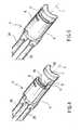
- the surgical stapling device 4comprises, in its distal end region, an end effector 5, particularly a staple fastening assembly, and in its proximal end region, a handle (not shown in the figures).
- the handle and the end effector 5are connected via one or more, e.g. two elongate flexible force transmitters 25 used for transmitting forces and/or movements from the proximal handle to the distal end effector 5 in order to position (e.g. advance and rotate) the end effector and to perform the stapling and cutting functions of the stapling device 4.
- the main components of the end effector 5are a cartridge device (proximal jaw 8), which contains several curved open rows of staples as well as a knife or cutting edge, and a curved anvil (distal jaw 7), which has a staple forming face and is adapted to cooperate with the cartridge device to form the ends of the staples expelled from the cartridge device when the stapling device 4 is "fired".
- proximal jaw 8which contains several curved open rows of staples as well as a knife or cutting edge
- a curved anvildistal jaw 7
- distal jaw 7which has a staple forming face and is adapted to cooperate with the cartridge device to form the ends of the staples expelled from the cartridge device when the stapling device 4 is "fired”.
- the anvil 7can be moved with respect to the cartridge device 8 in a parallel relationship, i.e. in a direction parallel to the longitudinal axis L of the end effector 5.
- the anvil 7is spaced apart from the cartridge device 8, while in Fig. 3 and 5 , the same anvil 7 has been entirely moved towards the cartridge device 8.
- the mechanism and its components of the stapling device 4 used for moving anvil 7 relative to cartridge device 8are generally called moving device, whereas the mechanism and the components used for advancing the staples are generally called staple driving device.
- the entire end effector 5is curved about the longitudinal (proximal - distal) axis L so that its shape adapts to the wall of natural ducts, such as the colon wall, without obstructing access space and visualization.
- a lateral end of the anvil 7 and a corresponding lateral end of the cartridge device 8are connected by the longitudinally extending lateral shaft 9 so that a substantially C shaped frame is formed which defines the window 6 for receiving the target tissue 1 and the lateral opening 10 opposite the lateral shaft 9 and configured to provide lateral access to the window 6.
- the cutting and stapling meansact along the theoretical curved surface of the aperture of window 6 in order to act exactly on the target tissue placed in that window 6.
- the lateral opening 10provides a substantially tangentially or circumferentially oriented access aperture to the window 6, while the window 6 itself provides a substantially radially oriented (with respect to the longitudinal axis L) through opening for receiving the target tissue 1 during stapling and cutting.
- a lateral end 28 of the curved anvil 7 opposite the lateral shaft 9is radially tapered from a radially external side 26 towards a radially internal side 27 so that it defines an edge 29 extending substantially parallel to the longitudinal axis L of the end effector 5.
- the edge 29is preferably blunt and facilitates the above mentioned rotational scooping of the target tissue 1 in order to place it in the window 6 between the anvil 7 and the cartridge device 8.
- the surgical stapling device 4is adapted to be slit along an endoscope during advancement to the target tissue 1, to perform the above mentioned rotational movement about the longitudinal axis L in order to place the target tissue 1 between the jaws embodied by the anvil and cartridge device and to keep the endoluminal operational site clear, thereby providing a good visualization and access.
- the traction meansneed not be inserted through the window 6 prior to grasping the tissue or prior to insertion of the traction means or of the surgical stapler into the body of the patient.
Landscapes
- Health & Medical Sciences (AREA)
- Life Sciences & Earth Sciences (AREA)
- Surgery (AREA)
- Heart & Thoracic Surgery (AREA)
- Engineering & Computer Science (AREA)
- Biomedical Technology (AREA)
- Nuclear Medicine, Radiotherapy & Molecular Imaging (AREA)
- Medical Informatics (AREA)
- Molecular Biology (AREA)
- Animal Behavior & Ethology (AREA)
- General Health & Medical Sciences (AREA)
- Public Health (AREA)
- Veterinary Medicine (AREA)
- Surgical Instruments (AREA)
- Sampling And Sample Adjustment (AREA)
Abstract
Description
- The present invention concerns a device for endoluminally or laparoscopically grasping and excising a tissue sample from areas in a patient's body. In particular, the present invention concerns a device to be used in a method suitable for covering low and high gastrointestinal portions, laparoscopic approaches and more advanced transgastric, transvaginal or transanal/rectal approaches.
- There is a great need for instruments for endoluminally or laparoscopically excising a tissue sample from areas in a patient's body so as to allow the safe and effective removal of a tissue sample, for example a lesion. In particular, there is a need for instruments for excising a determined and precise amount of tissue allowing better control of the visual field during each step of the method.
- It is known to grasp and excise tissue samples by conventional open surgery. The disadvantages of conventional surgical methods are well known; for example, they are very invasive, the patient needs to be anaesthetised and the post-operation recovery time is long.
- In order to overcome the drawbacks of the conventional open surgery approach, a device for endoluminally grasping and excising a tissue sample from areas in a patient's body has been proposed in the yet unpublished co-pending patent application MI2006A000411 by the same applicant. According to this endoluminal approach, a distal portion of a grasper is introduced into the patient's body and fixed to the tissue to be excised. A surgical stapling device is provided having a distal end with a window for receiving the tissue to be excised and comprising cutting and stapling means that act through that window, The surgical stapling device is introduced into the patient's body and its distal end is positioned close to the tissue to be excised. Then, traction is exerted on the traction means by which an amount of tissue is pulled through the window and positioned for cutting and stapling. After positioning of the amount of tissue, the latter is cut and stapled by actuating the cutting and stapling means of the surgical stapling device through the window.
US 7,118,528 B1 discloses a known surgical instrument assembly for the treatment of haemorrhoids andWO 01/91646 A1 - While the above described devices allow reducing the invasiveness of the surgical intervention, the limited size of the window of the surgical stapling device limits the amount of tissue that can be grasped and excised. Moreover, the surgical stapling device may at least partially obstruct the access to the tissue. As a consequence, an extensive articulation of the endoscope might be necessary in order to obtain a good visualization inside the window and to approach the tissue at the correct angle. Furthermore, the window configuration of the surgical stapling device requires the grasping and traction device to be inserted through the window opening and the visual field is partially occupied by the surgical stapling device, thereby hindering the visual detection (e.g. by an endoscope) of the most appropriate location for grasping the tissue.
- It is therefore an object of the present invention to provide a device for endoluminally or laparoscopically excising a tissue sample enabling an improved visualization during detection and grasping the tissue.
- Within the scope of the main object, another object of the present invention is to provide a device for endoluminally or laparoscopically excising a tissue sample enabling an increased amount of tissue to be grasped and excised.
- Yet another object of the present invention is to provide a device for endoluminally excising a tissue sample carried out along the entire length of the colon up to the caecum.
- These and other objects are obtained by a surgical device according to claim 1. The dependent claims cover embodiments of the invention.
- The details and advantages of the present invention shall be made apparent from the accompanying drawings and the description thereof, which illustrate embodiments of the invention and serve to explain the principles of the present invention.
Figure 1 shows a longitudinally sectioned portion of the colon and a surgical stapling device and a grasping device during the performance of the method for grasping and excising tissue described in the unpublished patent application MI2006A000411;Figure 2 is a perspective distal lateral view of a surgical stapling device according to the invention in an open configuration;Figure 3 is a perspective distal lateral view of the surgical stapling device infigure 2 in a closed configuration;Figure 4 is another perspective distal lateral view of the surgical stapling device infigure 2 in an open configuration;Figure 5 shows the surgical stapling device infigure 4 in a closed configuration;Figures 6, 7 and 8 are several side views of the surgical stapling device in an open configuration;Figures 9 to 14 show a longitudinally sectioned colon and a surgical staple device, a grasping device and an endoscope performing a method for endoluminally grasping and excising a tissue sample;Figures 15 to 19 show a longitudinally sectioned colon and a protective sheath, a grasping device and an endoscope performing several steps of a method for endoluminally grasping and excising a tissue sample ;- The terms "proximal" and "distal" are referred to the surgeon's point of view if not expressly otherwise indicated. The terms "lateral" and "radial" refer to the longitudinal axis L (extending in a proximal-distal direction) of an end effector of a surgical stapling device or to the longitudinal axis of a hollow organ, such as the colon, in which the operation takes place or to the longitudinal axis (proximal-distal direction) of other surgical instruments and devices which will be described in detail below.
- In the figures, a portion of target tissue intended to be excised is generally denoted by reference numeral 1. The target tissue 1 might correspond to an entire lesion or other abnormality that need to be examined or removed or might be only a part of such a lesion or abnormality.
- Generally, the method according to the present invention comprises the steps of:
- providing traction means 2 having a
distal portion 3, suitable for being fixed to at least one portion of the target tissue 1, and a proximal portion, - introducing the
distal portion 3 of the traction means 2 into the patient's body and positioning thedistal portion 3 of the traction means 2 close to the target tissue 1, so that at least one portion of the traction means 2 that extends from thedistal portion 3 is positioned in the patient's body, - fixing the
distal portion 3 of the traction means 2 to at least one portion of the target tissue 1, - providing a
surgical stapling device 4 having adistal end effector 5 with awindow 6 for receiving the target tissue 1 and comprising cutting and stapling means that act through thatwindow 6, wherein thewindow 6 is defined by a substantially C shaped frame comprising a distal jaw 7 (e.g. a curved anvil) and an opposite proximal jaw 8 (e.g. a staple cartridge device) connected to each other by alateral shaft 9 as well as alateral opening 10 opposite thelateral shaft 9, - introducing the
surgical stapling device 4 into the patient's body and positioning theend effector 5 of thesurgical stapling device 4 laterally to the target tissue 1 so that thelateral opening 10 is facing towards the target tissue 1, - moving the
end effector 5 laterally or rotating theend effector 5 about its longitudinal axis L so that the target tissue enters thewindow 6 through thelateral opening 10, - exerting traction on the traction means 2, thereby pulling an amount of tissue through the
window 6, - cutting and stapling the target tissue 1 by actuating the cutting and stapling means of said
surgical stapling device 4 through thewindow 6. - Finally, all of the devices are withdrawn and the sample fixed to the traction means is removed from the patient's body.
- According to an embodiment, the
distal portion 3 of the traction means 2 comprises at least onesnare 11 and the step of fixing thedistal portion 3 of the traction means 2 to at least one portion of the target tissue 1 is carried out by lassoing thesnare 11 around the target tissue 1, e.g. a benign adenoma. Moreover, thesnare 11 is connected to adistal end 12 of a wire orsuture 13 of the traction means 2 to traction the tissue during the rotational movement of theend effector 5 to scoop the target tissue 1 laterally into thewindow 6 between the opposite distal andproximal jaws window 6. Indeed, the wire orsuture 13 extends between thedistal end 12 and a proximal end corresponding to the proximal portion of the traction means 2. - In accordance with an embodiment, the
snare 11 is connected to a ring or similar handle (not shown in the figures) formed at a distal end of the wire orsuture 13 in order to facilitate traction and pulling of the target tissue 1. - In accordance with an alternative embodiment, the
distal portion 3 of the traction means 2 comprises at least one grasper and the step of fixing thedistal portion 3 of the traction means 2 to at least one portion of the target tissue 1 is carried out by applying the grasper to the target tissue 1. In this case, the wire orsuture 13 and the proximal handle or ring of the traction device can be embodied as described above with reference to the snare traction device. - As shall be described in greater detail, the step of exerting traction on the traction means 2 can comprise the step of extracorporeally pulling the proximal end of the wire or
suture 13. - According to a different embodiment of the invention, not shown in figures, the step of exerting traction on the traction means can comprise the step of pulling the proximal end of the wire or
suture 13 by means of a further grasping device. - According to an embodiment, the step of applying the
distal portion 3 of the traction means 2 to the target tissue 1 and/or the step of exerting a traction on the traction means 2 is carried out under the control of avisualization device 14. In particular, during the step of applying thedistal portion 3 of the traction means 2 to the target tissue 1 and/or the step of exerting a traction on said traction means 2, a portion of the wire orsuture 13 extends through the visualization device 14 (Figures 10 and19 ) by which the proximal end of the wire orsuture 13 comes out from the proximal end of thevisualization device 14 and thedistal end 12 of the wire orsuture 13 comes out from adistal end 15 of thevisualization device 14. - According to a different embodiment of the invention, not shown in figures, during the step of applying the
distal portion 3 of the traction means 2 to the target tissue 1 and/or the step of exerting a traction on said traction means, a portion of said wire orsuture 13 extends along an outer surface of avisualization device 14. - In accordance with yet another embodiment, the traction means 2 comprise at least one clip 17 (
figures 18, 19 ). Theclip 17 might be connected to the wire orsuture 13 whilst theclip 17 is formed in the target tissue 1 and fixed to it. - According to an embodiment, the step of introducing the at least one
clip 17 into the patient's body and fixing it in the target tissue 1 is carried out by means of agrasping device 16 that grasp the tissue before fixing the clip to it. For example, thegrasping device 16 can be used to introduce and fix theclip 17 with the wire orsuture 13 to the target tissue 1 and, after having introduced thesurgical stapling device 4, to pull the proximal end of the wire orsuture 13 before cutting and stapling the target tissue 1. - According to an embodiment, as shown e.g. in
figures 10 and 11 as well as infigures 18 and 19 , also the step of introducing the traction means 2 into the patient's body is carried out under the control of a visualization device. In particular, the step of introducing the traction means 2 into the patient's body comprises the step of inserting the traction means 2 through thevisualization device 14 outside of the patient's body, and then introducing thevisualization device 14 and the traction means 2 into the patient's body. In this case, the wire orsuture 13 can be inserted into aninstrument channel 18 of thevisualization device 14, before or after introducing thevisualization device 14, e.g. endoluminally, into the patient's body. According to a different embodiment that is not illustrated, the wire orsuture 13 can extend along the outside of thevisualization device 14 before introducing thevisualisation device 14 into the patient's body. - According to a generic embodiment of the invention, schematically illustrated in
figures 15 to 19 , the present method can also comprise a first step of providing atubular sheath 19 having adistal end 20 and a proximal end (not shown in the figures). Thesheath 19 defines awork channel 21 for receiving in particular the traction means 2 and thesurgical stapling device 4. Moreover, thesheath 19 is particularly suitable for protecting the walls from perforations, in particular the walls of the colon when the present method is carried out endoluminally in order to excise a tissue sample of the colon. - According to an embodiment, the
sheath 19 is introduced into the patient's body and thedistal end 20 of thesheath 19 is positioned close to the target tissue 1 before fixing the traction means 2 to the target tissue 1. Such asheath 19 can be used in different embodiments of the method, for example having different types of traction means or different types of sheaths. Particularly, the method steps involving the use of a protective sheath can be performed also in connection with the illustration infigures 9 to 14 . - The
sheath 19 is also introduced into the patient's body by means of a visualization device that can be the same visualization device referred to as 14. - Before introducing the
sheath 19 into the patient's body, thevisualization device 14 is inserted through thesheath 19, from its proximal end up to and possibly beyond itsdistal end 20. Thereafter, thevisualization device 14 is fixed to thesheath 19 and both are introduced together into the patient's body (Figure 15 ). - The step of fixing the
sheath 19 to thevisualization device 14 can be carried out as follows. Thevisualization device 14 is introduced through thesheath 19 from the proximal end to the distal end of thesheath 19 so that thedistal end 15 of thevisualization device 14 exits from thedistal end 20 of thesheath 19. Then thevisualization device 14 is fixed to thesheath 19 by attaching anelastic connection sheath 22 on thedistal end 20 of thesheath 19 and on thedistal end 15 of thevisualization device 14, before introducing the entire assembly ofvisualization device 14,sheath 19 and elastic connectingsheath 22 into the patient's body (Figure 15 ). - The
visualization device 14 is proximally withdrawn from thesheath 19 before introducing the traction means 2 through the sheath 19 (Figures 16 and 17 ). By using anelastic connection sheath 22 to fix thesheath 19 to thevisualization device 14, the step of withdrawing thevisualization device 14 from thesheath 19 may be performed by thrusting thevisualization device 14 distally, thereby pulling the elastic connection sheath 22 (which is firmly connected to thedistal end 15 of the visualization device 14) from thedistal end 20 of the sheath 19 (Figure 16 ) and subsequently withdrawing thevisualization device 14 together with the connectingsheath 22 proximally through thework channel 21 of the sheath 19 (Figure 17 ). - After the positioning of the
sheath 19, the step of introducing the traction means 2 into the patient's body is carried out by passing the traction means 2 through thework channel 21 of thesheath 19 up to the target tissue 1. In order to adequately guide the instruments and at the same time protect the natural duct (e.g. the colon wall) thesheath 19 can be insufflated or can be naturally expanded by introducing the instruments and devices. - Preferably the step of introducing the traction means 2 into the patient's body comprises the step of inserting the distal
tissue connection portion 3, e.g. the grasper or the snare, through a visualization device outside of the patient's body, and then of introducing the visualization device and thetissue connection portion 3 into thework channel 21 of thesheath 19 to fix the traction means 2 to the target tissue (Figure 19 ). The visualization device can be the same visualization device for all of the steps, i.e. the visualization device referred to byreference numeral 14 in the drawings. - The step of introducing the
surgical stapling device 4 into the patient's body is generically carried out by inserting thesurgical stapling device 4 distally through thework channel 21 ofsheath 19 up to itsdistal end 20. Theend effector 5 of thesurgical stapling device 4 is then pushed distally out of thesheath 19 and positioned laterally to the target tissue 1 so that thelateral opening 10 of theend effector window 6 is facing towards the target tissue 1. By moving theend effector 5 laterally or by rotating theend effector 5 about its longitudinal axis L so that the target tissue 1 enters thewindow 6 through thelateral opening 10, the target tissue 1 enters the space between the distal andproximal jaws surgical stapling device 4 the target tissue 1 can be held in position by pulling the traction means 2. After the target tissue has been laterally introduced (by a scoop - like movement) in between thejaws end effector 5, it can be further pulled by means of the traction means 2 in order to obtain the desired tissue positioning in thewindow 6 of thesurgical stapling device 4 prior to perform cutting and stapling through thewindow 6 in order to excise the portion of target tissue 1. - The step of rotating the end effector about the longitudinal axis L may be carried out by extracorporeally rotating a proximal end portion of the surgical stapling device. An alternative surgical stapling device is provided in which the end effector is rotatably movable with respect to an insertion shaft or force transmitter connecting the end effector to a distal handle and which comprises an end effector rotating mechanism adapted to rotate the end effector about its longitudinal axis L in response to a manual operation of an actuating knob or lever which is arranged at the handle and cooperates with the end effector rotating mechanism. In this case, the step of rotating the end effector about the longitudinal axis L may be carried out by operating the actuating knob or lever.
- The step of rotating the end effector about the longitudinal axis L may be carried out by torsionally coupling the end effector to the visualization device and rotating the visualization device about an axis parallel to the longitudinal axis L.
- Then all of the devices are withdrawn from the patient's body and the excised sample is taken out by means of the traction means 2.
- As has already been mentioned, the hitherto described method is particularly suitable for being carried out according to an endoluminal approach, using natural or artificial orifices. However, the method described can also be carried out according to a laparoscopic approach. With reference to all of the embodiments described, the step of fixing the traction means 2 to at least one portion of the target tissue 1 can comprise the step of fixing a plurality of combined or single clips and/or snares and/or graspers of the traction means to the target tissue 1. Each clip and/or snare and/or grasper of said plurality of combined or single clips, snares or graspers is connected to a wire or
suture 13 to hold the target tissue 1 during the rotational movement of theend effector 5 to laterally embrace the target tissue 1 and position it in thewindow 6 and, possibly, to subsequently pull the target tissue 1 further through thewindow 6 prior to cutting and stapling. - Said clips or graspers are fixed along a border of the portion of the target tissue. Alternatively, at least one clip or grasper is fixed directly to the portion of the target tissue 1. In case of pedunculated polyps, a snare is preferably lassoed around the stalk of the polyp.
- With reference to all of the embodiments described, the method of using the present invention can comprise the step of highlighting the target tissue 1 through marks or tattoos and, whilst a traction is exerted on the traction means, of monitoring the amount of tissue positioned in and pulled through the
window 6 of thesurgical stapling device 4 by checking the position of the marks or of the tattoos. - A further, more specific illustrative example of an endoluminal excision of a benign adenoma at the colon wall of a patient will be given below with reference to
figures 9 to 14 . - In a first step of the method (
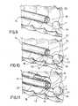
Figure 9 ), acolonoscope 14 is introduced transanally through theentire colon 23 up to the caecum and then slowly withdrawn proximally to visualize the colon wall in order to individualize and locate colonic lesions. In the illustrative example offigure 9 , a benign pedunculated adenoma (target tissue 1) is identified. - In order to hold and traction the adenoma during the following steps of the method, an
endoscopic snare instrument channel 18 of thecolonoscope 14 until it exits thecolonoscope 14 at its distal end 15 (Figure 10 ). Thesnare 11 is positioned about the adenoma and lassoed around its stalk 24 (even though the figures show a schematically wide open snare, it is of course intended to tighten thesnare 11 around the lesion in order to fixate it properly to the tissue). After having thesnare 11 attached to the adenoma, thesurgical stapling device 4 is transanally introduced into the colon and advanced along thecolonoscope 14 up to itsdistal end 15. During transanal introduction and distal advancing of thesurgical stapling device 4, thedistal end effector 5 is held in a fully closed configuration, that is the distal andproximal jaws - The
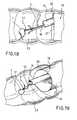
jaws end effector 5 are then fully opened thereby opening thewindow 6 therebetween and also widening thelateral opening 10. Under continuous endoscopic visualization by thecolonoscope 14, theend effector 5 is now advanced distally and positioned laterally to the previously grasped adenoma (target tissue 1) so that thelateral opening 10 directly faces the portion of target tissue 1 intended to be placed in thewindow 6 between the distal andproximal jaws 7, 8 (Figure 12 ). Theend effector 5 is then rotated about its longitudinal axis L in order to embrace (e.g. in a scoop like manner) the adenoma from the side so that it enters thewindow 6 through the lateral opening 10 (Figure 13 ). - With the adenoma placed in the
window 6 of theend effector 5, it can now be tractioned from outside the body by means of thesnare 11 and the associatedwire 13 until the desired amount of tissue volume is captured. - Then the
jaws end effector 5 is actuated to apply the staples to the tissue and to cut the latter adjacent the stapled seam, thereby excising the colonic adenoma (Figure 14 ). - Then, the
jaws colonoscope 14. - Finally, the
colonoscope 14, thesurgical stapling device 4 and the traction means 2 holding the excised lesion are proximally withdrawn from the target site and out of the body of the patient. - Those skilled in the art will have appreciated from the foregoing description that the method of using the invention reduces the invasiveness with respect to known methods and provides an improved visualization during detection, grasping and positioning of the tissue in the end effector of the surgical stapling device in an endoluminal or laparoscopic approach. Moreover, said method allows to increase the amount of target tissue that can be grasped and excised.
- According to the invention and in order to facilitate the implementation of the above described method, the
surgical stapling device 4 comprises, in its distal end region, anend effector 5, particularly a staple fastening assembly, and in its proximal end region, a handle (not shown in the figures). The handle and theend effector 5 are connected via one or more, e.g. two elongateflexible force transmitters 25 used for transmitting forces and/or movements from the proximal handle to thedistal end effector 5 in order to position (e.g. advance and rotate) the end effector and to perform the stapling and cutting functions of thestapling device 4. - The main components of the
end effector 5 are a cartridge device (proximal jaw 8), which contains several curved open rows of staples as well as a knife or cutting edge, and a curved anvil (distal jaw 7), which has a staple forming face and is adapted to cooperate with the cartridge device to form the ends of the staples expelled from the cartridge device when thestapling device 4 is "fired". - The
anvil 7 can be moved with respect to thecartridge device 8 in a parallel relationship, i.e. in a direction parallel to the longitudinal axis L of theend effector 5. In the views ofFig. 2 ,4 and6 , theanvil 7 is spaced apart from thecartridge device 8, while inFig. 3 and5 , thesame anvil 7 has been entirely moved towards thecartridge device 8. The mechanism and its components of thestapling device 4 used for movinganvil 7 relative tocartridge device 8 are generally called moving device, whereas the mechanism and the components used for advancing the staples are generally called staple driving device. - For the sake of simplicity, in the present description the above mentioned moving device and staple driving device will be referred to as a whole with the term "actuating mechanism" of the
surgical stapling device 4. As the detailed description of one possible embodiment of such an actuating mechanism is concerned, such a description is disclosed in the applicant's co-pending international patent applicationWO 2006/027014 ,figures 4 to 15 and the corresponding parts of the description which are herewith included for reference. - In accordance with the invention, the
entire end effector 5 is curved about the longitudinal (proximal - distal) axis L so that its shape adapts to the wall of natural ducts, such as the colon wall, without obstructing access space and visualization. - A lateral end of the
anvil 7 and a corresponding lateral end of thecartridge device 8 are connected by the longitudinally extendinglateral shaft 9 so that a substantially C shaped frame is formed which defines thewindow 6 for receiving the target tissue 1 and thelateral opening 10 opposite thelateral shaft 9 and configured to provide lateral access to thewindow 6. The cutting and stapling means act along the theoretical curved surface of the aperture ofwindow 6 in order to act exactly on the target tissue placed in thatwindow 6. - In other words, the
lateral opening 10 provides a substantially tangentially or circumferentially oriented access aperture to thewindow 6, while thewindow 6 itself provides a substantially radially oriented (with respect to the longitudinal axis L) through opening for receiving the target tissue 1 during stapling and cutting. - According to the invention, a
lateral end 28 of thecurved anvil 7 opposite thelateral shaft 9 is radially tapered from a radiallyexternal side 26 towards a radiallyinternal side 27 so that it defines anedge 29 extending substantially parallel to the longitudinal axis L of theend effector 5. Theedge 29 is preferably blunt and facilitates the above mentioned rotational scooping of the target tissue 1 in order to place it in thewindow 6 between theanvil 7 and thecartridge device 8. - Thanks to the particular shape and structural configuration of the
surgical stapling device 4, it is adapted to be slit along an endoscope during advancement to the target tissue 1, to perform the above mentioned rotational movement about the longitudinal axis L in order to place the target tissue 1 between the jaws embodied by the anvil and cartridge device and to keep the endoluminal operational site clear, thereby providing a good visualization and access. - Moreover, thanks to the
lateral opening 10, the traction means need not be inserted through thewindow 6 prior to grasping the tissue or prior to insertion of the traction means or of the surgical stapler into the body of the patient.
Claims (8)
- Surgical device for endoluminally or laparoscopically grasping and excising a target tissue (1) sample from areas in a patient's body, comprising a surgical stapling device (4) having a distal staple fastening assembly (5) connected via one or more force transmitters (25) to a proximal handle,
wherein the staple fastening assembly (5) comprises:- a cartridge device (8) containing one or more curved open rows of staples as well as a knife,- a curved anvil (7) having a staple forming face adapted to cooperate with the cartridge device (8) to form the ends of the staples expelled from the cartridge device (8),wherein the anvil (7) is movable with respect to the cartridge device (8) along a longitudinal axis (L) of the staple fastening assembly (5),
wherein the staple fastening assembly (5) is curved about the longitudinal axis (L) and forms two opposite lateral ends,
characterized in that said one or more force transmitters (25) are flexible,in that only one lateral end of the anvil (7) is connected to a corresponding lateral end of the cartridge device (8) by a longitudinally extending lateral shaft (9), so that a substantially C shaped frame is formed which defines a window (6) for receiving the target tissue (1) and a lateral opening (10) opposite the lateral shaft (9) configured to provide lateral access to the window (6) andin that a free lateral end (28) of the curved anvil (7) opposite said lateral shaft (9) is radially tapered from a radially external side (26) towards a radially internal side (27) so that it defines an edge (29) extending substantially parallel to the longitudinal axis (L). - Surgical device according to claim 1, wherein said lateral opening (10) is configured to provide a substantially tangentially or circumferentially oriented access aperture to the window (6) and the window (6) itself provides a substantially radially oriented through opening for receiving the target tissue 1 with respect to the longitudinal axis L.
- Surgical device according to claim 1 or 2, wherein said edge (29) is blunt.
- Surgical device according to any one of the preceding claims, wherein the staple fastening assembly (5) is rotatably movable with respect to the force transmitter (25) and the surgical stapling device (4) comprises a rotating mechanism adapted to rotate the staple fastening assembly (5) about its longitudinal axis (L) in response to an actuation of an actuating knob or lever which is arranged at the handle and which cooperates with said rotating mechanism.
- Surgical device according to any one of the preceding claims, comprising traction means (2) with a distal tissue connection portion (3) and a wire or suture (13) connected to said distal tissue connection portion (3).
- Surgical device according to claim 5, wherein said distal tissue connection portion (3) is selected from the group comprising:- a snare (11),- a grasping device (16),- a clip (17).
- Surgical device according to any one of the claims 5 or 6, comprising a visualization device (14), such as an endoscope or laparoscope, having an instrument channel (18) adapted to receive the traction means (2).
- Surgical device according to any one of the preceding claims, comprising a protective sheath (19) adapted to be inserted in a natural duct of the patient's body and defining a work channel (21) adapted to receive the surgical stapling device (4) and a visualization device (14) .
Priority Applications (9)
| Application Number | Priority Date | Filing Date | Title |
|---|---|---|---|
| DE602006012342TDE602006012342D1 (en) | 2006-12-04 | 2006-12-04 | Apparatus for endoluminal or laparoscopic grasping and excision of a tissue sample from a patient's body |
| EP06024997AEP1929963B1 (en) | 2006-12-04 | 2006-12-04 | Device for endoluminally or laparoscopically grasping and excising a tissue sample from areas in a patient's body |
| AT06024997TATE457685T1 (en) | 2006-12-04 | 2006-12-04 | DEVICE FOR ENDOLUMINAL OR LAPAROSCOPIC ACQUISITION AND CUTTING A TISSUE SAMPLE FROM A PATIENT'S BODY |
| JP2009539683AJP5208959B2 (en) | 2006-12-04 | 2007-10-18 | A device for grasping and excising tissue samples from areas within a patient's body in a cavity or laparoscopically |
| PCT/EP2007/061123WO2008068107A1 (en) | 2006-12-04 | 2007-10-18 | Device for endoluminally or laparoscopically grasping and excising a tissue sample from areas in a patient's body |
| BRPI0720179-6A2ABRPI0720179A2 (en) | 2006-12-04 | 2007-10-18 | DEVICE FOR ENDOLUMINAL OR LAPAROSCOPIC TIGHTENING AND EXCISION OF A FABRIC SAMPLE OF A PATIENT BODY AREAS |
| RU2009125529/14ARU2454956C2 (en) | 2006-12-04 | 2007-10-18 | Device for endoluminal or laparoscopic gripping and cutting out tissue sample from patient's body regions |
| CN2007800446909ACN101547651B (en) | 2006-12-04 | 2007-10-18 | Device for endoluminally or laparoscopically grasping and excising a tissue sample from areas in a patient's body |
| CA2671491ACA2671491C (en) | 2006-12-04 | 2007-10-18 | Device for endoluminally or laparoscopically grasping and excising a tissue sample from areas in a patient's body |
Applications Claiming Priority (1)
| Application Number | Priority Date | Filing Date | Title |
|---|---|---|---|
| EP06024997AEP1929963B1 (en) | 2006-12-04 | 2006-12-04 | Device for endoluminally or laparoscopically grasping and excising a tissue sample from areas in a patient's body |
Publications (2)
| Publication Number | Publication Date |
|---|---|
| EP1929963A1 EP1929963A1 (en) | 2008-06-11 |
| EP1929963B1true EP1929963B1 (en) | 2010-02-17 |
Family
ID=38042579
Family Applications (1)
| Application Number | Title | Priority Date | Filing Date |
|---|---|---|---|
| EP06024997AActiveEP1929963B1 (en) | 2006-12-04 | 2006-12-04 | Device for endoluminally or laparoscopically grasping and excising a tissue sample from areas in a patient's body |
Country Status (9)
| Country | Link |
|---|---|
| EP (1) | EP1929963B1 (en) |
| JP (1) | JP5208959B2 (en) |
| CN (1) | CN101547651B (en) |
| AT (1) | ATE457685T1 (en) |
| BR (1) | BRPI0720179A2 (en) |
| CA (1) | CA2671491C (en) |
| DE (1) | DE602006012342D1 (en) |
| RU (1) | RU2454956C2 (en) |
| WO (1) | WO2008068107A1 (en) |
Families Citing this family (10)
| Publication number | Priority date | Publication date | Assignee | Title |
|---|---|---|---|---|
| US9808146B2 (en)* | 2011-12-02 | 2017-11-07 | Interscope, Inc. | Endoscopic tool for debriding and removing polyps |
| RU2606453C2 (en)* | 2011-12-03 | 2017-01-10 | Конинклейке Филипс Н.В. | Automatic depth scrolling and orientation adjustment for semi-automated path planning |
| WO2015027166A2 (en)* | 2013-08-23 | 2015-02-26 | Covidien Lp | Specimen retrieval device |
| CN104116526B (en)* | 2014-07-11 | 2017-05-24 | 诸暨市鹏天医疗器械有限公司 | Tool combining biopsy forceps and snare |
| ES2727963T3 (en)* | 2014-07-22 | 2019-10-21 | Eximis Surgical Llc | Large volume tissue reduction and extraction system |
| CN105640615B (en)* | 2016-02-22 | 2018-05-29 | 苏州大学附属儿童医院 | Endoscopic surgery knife with pulling device |
| EP3965665A1 (en)* | 2019-07-24 | 2022-03-16 | Boston Scientific Scimed, Inc. | Device for fastening tissue |
| WO2021027589A1 (en)* | 2019-08-12 | 2021-02-18 | 杭州德晋医疗科技有限公司 | Recoverable valve clamp and valve clamp recovery system |
| CN115317079A (en)* | 2022-07-22 | 2022-11-11 | 上海欣吉特生物科技有限公司 | Artificial valve leaflet resection device and application |
| CN119279731A (en)* | 2024-12-11 | 2025-01-10 | 科瑞迈吉(北京)医疗科技有限公司 | Implant capture and retrieval device |
Family Cites Families (11)
| Publication number | Priority date | Publication date | Assignee | Title |
|---|---|---|---|---|
| SU1736449A1 (en)* | 1989-12-04 | 1992-05-30 | Ставропольский государственный медицинский институт | Polypectomy attachment to flexible endoscopes |
| US5452836A (en)* | 1994-02-07 | 1995-09-26 | Ethicon Endo-Surgery, Inc. | Surgical stapling instrument with improved jaw closure and staple firing actuator mechanism |
| US6119913A (en)* | 1996-06-14 | 2000-09-19 | Boston Scientific Corporation | Endoscopic stapler |
| US6601749B2 (en)* | 1998-06-19 | 2003-08-05 | Scimed Life Systems, Inc. | Multi fire full thickness resectioning device |
| US6142933A (en)* | 1998-11-23 | 2000-11-07 | Ethicon Endo-Surgery, Inc. | Anoscope for hemorrhoidal surgery |
| DE10026683C2 (en)* | 2000-05-30 | 2003-07-10 | Ethicon Endo Surgery Europe | Surgical stapling device |
| JP3722729B2 (en)* | 2001-06-04 | 2005-11-30 | オリンパス株式会社 | Endoscope treatment device |
| US7118528B1 (en)* | 2004-03-16 | 2006-10-10 | Gregory Piskun | Hemorrhoids treatment method and associated instrument assembly including anoscope and cofunctioning tissue occlusion device |
| RU2275867C2 (en)* | 2004-05-05 | 2006-05-10 | Государственное образовательное учреждение системы высшего профессионального образования "Сибирский государственный медицинский университет" ( ГОУ ВПО СибГМУ) | Method for surgical treatment of chronic gastric erosions |
| CA2579606C (en)* | 2004-09-10 | 2012-04-17 | Ethicon Endo-Surgery, Inc. | Surgical stapling instrument |
| RU2352273C2 (en)* | 2007-02-02 | 2009-04-20 | Александр Александрович Вишневский | Surgical stapler for applying of arched linear seams in conditions of limited space |
- 2006
- 2006-12-04EPEP06024997Apatent/EP1929963B1/enactiveActive
- 2006-12-04DEDE602006012342Tpatent/DE602006012342D1/enactiveActive
- 2006-12-04ATAT06024997Tpatent/ATE457685T1/ennot_activeIP Right Cessation
- 2007
- 2007-10-18RURU2009125529/14Apatent/RU2454956C2/ennot_activeIP Right Cessation
- 2007-10-18JPJP2009539683Apatent/JP5208959B2/ennot_activeExpired - Fee Related
- 2007-10-18CACA2671491Apatent/CA2671491C/ennot_activeExpired - Fee Related
- 2007-10-18WOPCT/EP2007/061123patent/WO2008068107A1/enactiveApplication Filing
- 2007-10-18CNCN2007800446909Apatent/CN101547651B/ennot_activeExpired - Fee Related
- 2007-10-18BRBRPI0720179-6A2Apatent/BRPI0720179A2/ennot_activeIP Right Cessation
Also Published As
| Publication number | Publication date |
|---|---|
| CA2671491A1 (en) | 2008-06-12 |
| BRPI0720179A2 (en) | 2014-06-24 |
| CN101547651B (en) | 2012-04-18 |
| RU2009125529A (en) | 2011-01-20 |
| DE602006012342D1 (en) | 2010-04-01 |
| RU2454956C2 (en) | 2012-07-10 |
| CA2671491C (en) | 2015-03-31 |
| ATE457685T1 (en) | 2010-03-15 |
| JP2010511449A (en) | 2010-04-15 |
| WO2008068107A1 (en) | 2008-06-12 |
| EP1929963A1 (en) | 2008-06-11 |
| CN101547651A (en) | 2009-09-30 |
| JP5208959B2 (en) | 2013-06-12 |
Similar Documents
| Publication | Publication Date | Title |
|---|---|---|
| EP1929963B1 (en) | Device for endoluminally or laparoscopically grasping and excising a tissue sample from areas in a patient's body | |
| JP5165357B2 (en) | Tissue clamp for local endoluminal resection of tissue | |
| US10675033B2 (en) | Apparatus and method for resectioning gastro-esophageal tissue | |
| US7235089B1 (en) | Surgical apparatus and method | |
| EP1929959B1 (en) | A surgical device for transanally accessing the rectum of a patient | |
| US8353847B2 (en) | Method for endoluminally or laparoscopically excising a tissue sample from areas in a patient's body, traction means and kit | |
| US5868760A (en) | Method and apparatus for endolumenally resectioning tissue | |
| JP4566500B2 (en) | Surgical stapling instrument | |
| US20220330968A1 (en) | Devices, systems and methods for tissue resection | |
| US20030040764A1 (en) | Endoscopic resection devices and related methods of use | |
| JP2007313314A (en) | Lumen stabilizer for endoscopic mucosal resection |
Legal Events
| Date | Code | Title | Description |
|---|---|---|---|
| PUAI | Public reference made under article 153(3) epc to a published international application that has entered the european phase | Free format text:ORIGINAL CODE: 0009012 | |
| AK | Designated contracting states | Kind code of ref document:A1 Designated state(s):AT BE BG CH CY CZ DE DK EE ES FI FR GB GR HU IE IS IT LI LT LU LV MC NL PL PT RO SE SI SK TR | |
| AX | Request for extension of the european patent | Extension state:AL BA HR MK RS | |
| 17P | Request for examination filed | Effective date:20081201 | |
| AKX | Designation fees paid | Designated state(s):AT BE BG CH CY CZ DE DK EE ES FI FR GB GR HU IE IS IT LI LT LU LV MC NL PL PT RO SE SI SK TR | |
| AXX | Extension fees paid | Extension state:AL Payment date:20081201 Extension state:BA Payment date:20081201 Extension state:RS Payment date:20081201 Extension state:MK Payment date:20081201 Extension state:HR Payment date:20081201 | |
| 17Q | First examination report despatched | Effective date:20090129 | |
| GRAP | Despatch of communication of intention to grant a patent | Free format text:ORIGINAL CODE: EPIDOSNIGR1 | |
| GRAS | Grant fee paid | Free format text:ORIGINAL CODE: EPIDOSNIGR3 | |
| GRAA | (expected) grant | Free format text:ORIGINAL CODE: 0009210 | |
| AK | Designated contracting states | Kind code of ref document:B1 Designated state(s):AT BE BG CH CY CZ DE DK EE ES FI FR GB GR HU IE IS IT LI LT LU LV MC NL PL PT RO SE SI SK TR | |
| AX | Request for extension of the european patent | Extension state:AL BA HR MK RS | |
| REG | Reference to a national code | Ref country code:GB Ref legal event code:FG4D | |
| REG | Reference to a national code | Ref country code:CH Ref legal event code:EP | |
| REG | Reference to a national code | Ref country code:IE Ref legal event code:FG4D | |
| REF | Corresponds to: | Ref document number:602006012342 Country of ref document:DE Date of ref document:20100401 Kind code of ref document:P | |
| REG | Reference to a national code | Ref country code:NL Ref legal event code:VDEP Effective date:20100217 | |
| LTIE | Lt: invalidation of european patent or patent extension | Effective date:20100217 | |
| PG25 | Lapsed in a contracting state [announced via postgrant information from national office to epo] | Ref country code:ES Free format text:LAPSE BECAUSE OF FAILURE TO SUBMIT A TRANSLATION OF THE DESCRIPTION OR TO PAY THE FEE WITHIN THE PRESCRIBED TIME-LIMIT Effective date:20100528 Ref country code:IS Free format text:LAPSE BECAUSE OF FAILURE TO SUBMIT A TRANSLATION OF THE DESCRIPTION OR TO PAY THE FEE WITHIN THE PRESCRIBED TIME-LIMIT Effective date:20100617 Ref country code:LT Free format text:LAPSE BECAUSE OF FAILURE TO SUBMIT A TRANSLATION OF THE DESCRIPTION OR TO PAY THE FEE WITHIN THE PRESCRIBED TIME-LIMIT Effective date:20100217 Ref country code:PT Free format text:LAPSE BECAUSE OF FAILURE TO SUBMIT A TRANSLATION OF THE DESCRIPTION OR TO PAY THE FEE WITHIN THE PRESCRIBED TIME-LIMIT Effective date:20100617 | |
| PG25 | Lapsed in a contracting state [announced via postgrant information from national office to epo] | Ref country code:SI Free format text:LAPSE BECAUSE OF FAILURE TO SUBMIT A TRANSLATION OF THE DESCRIPTION OR TO PAY THE FEE WITHIN THE PRESCRIBED TIME-LIMIT Effective date:20100217 Ref country code:AT Free format text:LAPSE BECAUSE OF FAILURE TO SUBMIT A TRANSLATION OF THE DESCRIPTION OR TO PAY THE FEE WITHIN THE PRESCRIBED TIME-LIMIT Effective date:20100217 Ref country code:FI Free format text:LAPSE BECAUSE OF FAILURE TO SUBMIT A TRANSLATION OF THE DESCRIPTION OR TO PAY THE FEE WITHIN THE PRESCRIBED TIME-LIMIT Effective date:20100217 Ref country code:PL Free format text:LAPSE BECAUSE OF FAILURE TO SUBMIT A TRANSLATION OF THE DESCRIPTION OR TO PAY THE FEE WITHIN THE PRESCRIBED TIME-LIMIT Effective date:20100217 Ref country code:LV Free format text:LAPSE BECAUSE OF FAILURE TO SUBMIT A TRANSLATION OF THE DESCRIPTION OR TO PAY THE FEE WITHIN THE PRESCRIBED TIME-LIMIT Effective date:20100217 | |
| PG25 | Lapsed in a contracting state [announced via postgrant information from national office to epo] | Ref country code:SE Free format text:LAPSE BECAUSE OF FAILURE TO SUBMIT A TRANSLATION OF THE DESCRIPTION OR TO PAY THE FEE WITHIN THE PRESCRIBED TIME-LIMIT Effective date:20100217 Ref country code:RO Free format text:LAPSE BECAUSE OF FAILURE TO SUBMIT A TRANSLATION OF THE DESCRIPTION OR TO PAY THE FEE WITHIN THE PRESCRIBED TIME-LIMIT Effective date:20100217 Ref country code:NL Free format text:LAPSE BECAUSE OF FAILURE TO SUBMIT A TRANSLATION OF THE DESCRIPTION OR TO PAY THE FEE WITHIN THE PRESCRIBED TIME-LIMIT Effective date:20100217 Ref country code:BE Free format text:LAPSE BECAUSE OF FAILURE TO SUBMIT A TRANSLATION OF THE DESCRIPTION OR TO PAY THE FEE WITHIN THE PRESCRIBED TIME-LIMIT Effective date:20100217 Ref country code:CY Free format text:LAPSE BECAUSE OF FAILURE TO SUBMIT A TRANSLATION OF THE DESCRIPTION OR TO PAY THE FEE WITHIN THE PRESCRIBED TIME-LIMIT Effective date:20100217 Ref country code:EE Free format text:LAPSE BECAUSE OF FAILURE TO SUBMIT A TRANSLATION OF THE DESCRIPTION OR TO PAY THE FEE WITHIN THE PRESCRIBED TIME-LIMIT Effective date:20100217 Ref country code:GR Free format text:LAPSE BECAUSE OF FAILURE TO SUBMIT A TRANSLATION OF THE DESCRIPTION OR TO PAY THE FEE WITHIN THE PRESCRIBED TIME-LIMIT Effective date:20100518 | |
| PG25 | Lapsed in a contracting state [announced via postgrant information from national office to epo] | Ref country code:SK Free format text:LAPSE BECAUSE OF FAILURE TO SUBMIT A TRANSLATION OF THE DESCRIPTION OR TO PAY THE FEE WITHIN THE PRESCRIBED TIME-LIMIT Effective date:20100217 Ref country code:BG Free format text:LAPSE BECAUSE OF FAILURE TO SUBMIT A TRANSLATION OF THE DESCRIPTION OR TO PAY THE FEE WITHIN THE PRESCRIBED TIME-LIMIT Effective date:20100517 Ref country code:CZ Free format text:LAPSE BECAUSE OF FAILURE TO SUBMIT A TRANSLATION OF THE DESCRIPTION OR TO PAY THE FEE WITHIN THE PRESCRIBED TIME-LIMIT Effective date:20100217 | |
| PLBE | No opposition filed within time limit | Free format text:ORIGINAL CODE: 0009261 | |
| STAA | Information on the status of an ep patent application or granted ep patent | Free format text:STATUS: NO OPPOSITION FILED WITHIN TIME LIMIT | |
| 26N | No opposition filed | Effective date:20101118 | |
| PG25 | Lapsed in a contracting state [announced via postgrant information from national office to epo] | Ref country code:DK Free format text:LAPSE BECAUSE OF FAILURE TO SUBMIT A TRANSLATION OF THE DESCRIPTION OR TO PAY THE FEE WITHIN THE PRESCRIBED TIME-LIMIT Effective date:20100217 | |
| PG25 | Lapsed in a contracting state [announced via postgrant information from national office to epo] | Ref country code:MC Free format text:LAPSE BECAUSE OF NON-PAYMENT OF DUE FEES Effective date:20101231 | |
| REG | Reference to a national code | Ref country code:CH Ref legal event code:PL | |
| PG25 | Lapsed in a contracting state [announced via postgrant information from national office to epo] | Ref country code:LI Free format text:LAPSE BECAUSE OF NON-PAYMENT OF DUE FEES Effective date:20101231 Ref country code:CH Free format text:LAPSE BECAUSE OF NON-PAYMENT OF DUE FEES Effective date:20101231 Ref country code:IE Free format text:LAPSE BECAUSE OF NON-PAYMENT OF DUE FEES Effective date:20101204 | |
| PG25 | Lapsed in a contracting state [announced via postgrant information from national office to epo] | Ref country code:LU Free format text:LAPSE BECAUSE OF NON-PAYMENT OF DUE FEES Effective date:20101204 Ref country code:HU Free format text:LAPSE BECAUSE OF FAILURE TO SUBMIT A TRANSLATION OF THE DESCRIPTION OR TO PAY THE FEE WITHIN THE PRESCRIBED TIME-LIMIT Effective date:20100818 | |
| PG25 | Lapsed in a contracting state [announced via postgrant information from national office to epo] | Ref country code:TR Free format text:LAPSE BECAUSE OF FAILURE TO SUBMIT A TRANSLATION OF THE DESCRIPTION OR TO PAY THE FEE WITHIN THE PRESCRIBED TIME-LIMIT Effective date:20100217 | |
| REG | Reference to a national code | Ref country code:FR Ref legal event code:PLFP Year of fee payment:11 | |
| REG | Reference to a national code | Ref country code:FR Ref legal event code:PLFP Year of fee payment:12 | |
| PGFP | Annual fee paid to national office [announced via postgrant information from national office to epo] | Ref country code:DE Payment date:20181120 Year of fee payment:13 | |
| PGFP | Annual fee paid to national office [announced via postgrant information from national office to epo] | Ref country code:IT Payment date:20191209 Year of fee payment:14 Ref country code:FR Payment date:20191113 Year of fee payment:14 | |
| PGFP | Annual fee paid to national office [announced via postgrant information from national office to epo] | Ref country code:GB Payment date:20191206 Year of fee payment:14 | |
| REG | Reference to a national code | Ref country code:DE Ref legal event code:R119 Ref document number:602006012342 Country of ref document:DE | |
| PG25 | Lapsed in a contracting state [announced via postgrant information from national office to epo] | Ref country code:DE Free format text:LAPSE BECAUSE OF NON-PAYMENT OF DUE FEES Effective date:20200701 | |
| GBPC | Gb: european patent ceased through non-payment of renewal fee | Effective date:20201204 | |
| PG25 | Lapsed in a contracting state [announced via postgrant information from national office to epo] | Ref country code:FR Free format text:LAPSE BECAUSE OF NON-PAYMENT OF DUE FEES Effective date:20201231 Ref country code:IT Free format text:LAPSE BECAUSE OF NON-PAYMENT OF DUE FEES Effective date:20201204 | |
| PG25 | Lapsed in a contracting state [announced via postgrant information from national office to epo] | Ref country code:GB Free format text:LAPSE BECAUSE OF NON-PAYMENT OF DUE FEES Effective date:20201204 |